WO2022102300A1 - Medical connector - Google Patents
Medical connectorDownload PDFInfo
- Publication number
- WO2022102300A1 WO2022102300A1PCT/JP2021/037208JP2021037208WWO2022102300A1WO 2022102300 A1WO2022102300 A1WO 2022102300A1JP 2021037208 WJP2021037208 WJP 2021037208WWO 2022102300 A1WO2022102300 A1WO 2022102300A1
- Authority
- WO
- WIPO (PCT)
- Prior art keywords
- flow path
- valve
- medical connector
- male connector
- head
- Prior art date
- Legal status (The legal status is an assumption and is not a legal conclusion. Google has not performed a legal analysis and makes no representation as to the accuracy of the status listed.)
- Ceased
Links
Images


Classifications
- A—HUMAN NECESSITIES
- A61—MEDICAL OR VETERINARY SCIENCE; HYGIENE
- A61M—DEVICES FOR INTRODUCING MEDIA INTO, OR ONTO, THE BODY; DEVICES FOR TRANSDUCING BODY MEDIA OR FOR TAKING MEDIA FROM THE BODY; DEVICES FOR PRODUCING OR ENDING SLEEP OR STUPOR
- A61M39/00—Tubes, tube connectors, tube couplings, valves, access sites or the like, specially adapted for medical use
- A61M39/22—Valves or arrangement of valves
- A61M39/26—Valves closing automatically on disconnecting the line and opening on reconnection thereof
- A—HUMAN NECESSITIES
- A61—MEDICAL OR VETERINARY SCIENCE; HYGIENE
- A61M—DEVICES FOR INTRODUCING MEDIA INTO, OR ONTO, THE BODY; DEVICES FOR TRANSDUCING BODY MEDIA OR FOR TAKING MEDIA FROM THE BODY; DEVICES FOR PRODUCING OR ENDING SLEEP OR STUPOR
- A61M39/00—Tubes, tube connectors, tube couplings, valves, access sites or the like, specially adapted for medical use
- A61M39/02—Access sites
- A61M39/04—Access sites having pierceable self-sealing members
- A61M39/045—Access sites having pierceable self-sealing members pre-slit to be pierced by blunt instrument
- A—HUMAN NECESSITIES
- A61—MEDICAL OR VETERINARY SCIENCE; HYGIENE
- A61M—DEVICES FOR INTRODUCING MEDIA INTO, OR ONTO, THE BODY; DEVICES FOR TRANSDUCING BODY MEDIA OR FOR TAKING MEDIA FROM THE BODY; DEVICES FOR PRODUCING OR ENDING SLEEP OR STUPOR
- A61M39/00—Tubes, tube connectors, tube couplings, valves, access sites or the like, specially adapted for medical use
- A61M39/10—Tube connectors; Tube couplings
- A61M39/1011—Locking means for securing connection; Additional tamper safeties
- A—HUMAN NECESSITIES
- A61—MEDICAL OR VETERINARY SCIENCE; HYGIENE
- A61M—DEVICES FOR INTRODUCING MEDIA INTO, OR ONTO, THE BODY; DEVICES FOR TRANSDUCING BODY MEDIA OR FOR TAKING MEDIA FROM THE BODY; DEVICES FOR PRODUCING OR ENDING SLEEP OR STUPOR
- A61M39/00—Tubes, tube connectors, tube couplings, valves, access sites or the like, specially adapted for medical use
- A61M39/22—Valves or arrangement of valves
- A61M39/24—Check- or non-return valves
- A—HUMAN NECESSITIES
- A61—MEDICAL OR VETERINARY SCIENCE; HYGIENE
- A61M—DEVICES FOR INTRODUCING MEDIA INTO, OR ONTO, THE BODY; DEVICES FOR TRANSDUCING BODY MEDIA OR FOR TAKING MEDIA FROM THE BODY; DEVICES FOR PRODUCING OR ENDING SLEEP OR STUPOR
- A61M39/00—Tubes, tube connectors, tube couplings, valves, access sites or the like, specially adapted for medical use
- A61M39/10—Tube connectors; Tube couplings
- A61M2039/1033—Swivel nut connectors, e.g. threaded connectors, bayonet-connectors
- A—HUMAN NECESSITIES
- A61—MEDICAL OR VETERINARY SCIENCE; HYGIENE
- A61M—DEVICES FOR INTRODUCING MEDIA INTO, OR ONTO, THE BODY; DEVICES FOR TRANSDUCING BODY MEDIA OR FOR TAKING MEDIA FROM THE BODY; DEVICES FOR PRODUCING OR ENDING SLEEP OR STUPOR
- A61M39/00—Tubes, tube connectors, tube couplings, valves, access sites or the like, specially adapted for medical use
- A61M39/10—Tube connectors; Tube couplings
- A61M2039/1072—Tube connectors; Tube couplings with a septum present in the connector
- A—HUMAN NECESSITIES
- A61—MEDICAL OR VETERINARY SCIENCE; HYGIENE
- A61M—DEVICES FOR INTRODUCING MEDIA INTO, OR ONTO, THE BODY; DEVICES FOR TRANSDUCING BODY MEDIA OR FOR TAKING MEDIA FROM THE BODY; DEVICES FOR PRODUCING OR ENDING SLEEP OR STUPOR
- A61M39/00—Tubes, tube connectors, tube couplings, valves, access sites or the like, specially adapted for medical use
- A61M39/22—Valves or arrangement of valves
- A61M39/26—Valves closing automatically on disconnecting the line and opening on reconnection thereof
- A61M2039/261—Valves closing automatically on disconnecting the line and opening on reconnection thereof where the fluid space within the valve is increasing upon disconnection
- A—HUMAN NECESSITIES
- A61—MEDICAL OR VETERINARY SCIENCE; HYGIENE
- A61M—DEVICES FOR INTRODUCING MEDIA INTO, OR ONTO, THE BODY; DEVICES FOR TRANSDUCING BODY MEDIA OR FOR TAKING MEDIA FROM THE BODY; DEVICES FOR PRODUCING OR ENDING SLEEP OR STUPOR
- A61M39/00—Tubes, tube connectors, tube couplings, valves, access sites or the like, specially adapted for medical use
- A61M39/22—Valves or arrangement of valves
- A61M39/26—Valves closing automatically on disconnecting the line and opening on reconnection thereof
- A61M2039/263—Valves closing automatically on disconnecting the line and opening on reconnection thereof where the fluid space within the valve is decreasing upon disconnection
- A—HUMAN NECESSITIES
- A61—MEDICAL OR VETERINARY SCIENCE; HYGIENE
- A61M—DEVICES FOR INTRODUCING MEDIA INTO, OR ONTO, THE BODY; DEVICES FOR TRANSDUCING BODY MEDIA OR FOR TAKING MEDIA FROM THE BODY; DEVICES FOR PRODUCING OR ENDING SLEEP OR STUPOR
- A61M39/00—Tubes, tube connectors, tube couplings, valves, access sites or the like, specially adapted for medical use
- A61M39/22—Valves or arrangement of valves
- A61M39/26—Valves closing automatically on disconnecting the line and opening on reconnection thereof
- A61M2039/266—Valves closing automatically on disconnecting the line and opening on reconnection thereof where the valve comprises venting channels, e.g. to insure better connection, to help decreasing the fluid space upon disconnection, or to help the fluid space to remain the same during disconnection
- A—HUMAN NECESSITIES
- A61—MEDICAL OR VETERINARY SCIENCE; HYGIENE
- A61M—DEVICES FOR INTRODUCING MEDIA INTO, OR ONTO, THE BODY; DEVICES FOR TRANSDUCING BODY MEDIA OR FOR TAKING MEDIA FROM THE BODY; DEVICES FOR PRODUCING OR ENDING SLEEP OR STUPOR
- A61M39/00—Tubes, tube connectors, tube couplings, valves, access sites or the like, specially adapted for medical use
- A61M39/22—Valves or arrangement of valves
- A61M39/26—Valves closing automatically on disconnecting the line and opening on reconnection thereof
- A61M2039/267—Valves closing automatically on disconnecting the line and opening on reconnection thereof having a sealing sleeve around a tubular or solid stem portion of the connector
Definitions
- This disclosurerelates to medical connectors.
- a housinghaving a male connector attachment / detachment portion and forming a liquid flow path, and a closed position and a closed position for closing the male connector attachment / detachment portion.
- the valvehas a valve that can be raised and lowered with respect to the housing between the open position that allows the flow path in the male connector to communicate with the liquid flow path by being pushed down by the male connector against the urging force. It is known that the valve has a head that closes the male connector attachment / detachment portion in the closed state in the closed position, and a body portion that is connected to the lower end of the head and receives the urging force (for example, Patent Documents 1 to 1). 2).
- Medical connectorsare required to be less prone to bolus and backflow due to the male connector attachment / detachment operation to the male connector attachment / detachment part.
- Bolusmeans that the liquid in the medical connector is pushed out of the medical connector.
- Backflowmeans that liquid outside the medical connector is drawn into the medical connector.
- blood drawn from the body into the catheter by backflowmay solidify into a thrombus, and the bolus may administer the thrombus from the inside of the catheter into the body. ..
- the purpose of this disclosureis to provide a medical connector that can easily realize a neutral structure in which bolus and backflow are less likely to occur by attaching / detaching a male connector.
- the medical connectoras one aspect of the present disclosure includes a housing having a male connector attachment / detachment portion and forming a liquid flow path, a closed position for closing the male connector attachment / detachment portion, and a male against urging force from the closed position. It has a valve that can be raised and lowered with respect to the housing between the open position that allows the flow path in the male connector to communicate with the liquid flow path by being pushed down by the connector, and the valve is the valve. It has a head that closes the male connector attachment / detachment portion in a closed position and a body portion that is connected to the lower end of the head portion and receives the urging force, and the young ratio of the body portion is higher than that of the head portion. Is also big.
- the valvehas an internal flow path that allows the flow path in the male connector to communicate with the liquid flow path in an open state in which the valve passes through at least the body portion and is in the open position. Have.
- the internal flow pathis formed only by the inner surface of the valve.
- the internal flow pathhas an opening / closing end that passes through the head and opens as the valve descends.
- the opening / closing endis formed by a slit.
- the internal flow pathhas a side end that opens to the side surface of the body.
- the liquid flow pathhas a side opening that opens to the side surface of a storage chamber that accommodates the body portion so as to be able to move up and down, and the side opening has the internal flow at least in the open state. Facing the side edge of the road.
- the upper portion of the side endcommunicates with the open / closed end only through the lower portion of the side end that does not face the side opening in the open state.
- the internal flow pathincludes two side ends that open to the sides of the body, and the liquid flow path opens to the side of a containment chamber that accommodates the body in an ascending / descending manner.
- One of the side endsfaces the one side opening in both the closed and open states, and the other side end faces the closed and open states. In either case, it faces the other side opening.
- the two side endsare provided so as to face each other.
- the internal flow pathhas a vertical flow path extending downward from the opening / closing end and a horizontal flow path extending from the lower end of the vertical flow path to both sides, and has a lower surface of the horizontal flow path.
- the bodyhas a shoulder extending laterally from the lower end of the head.
- the body portionhas an upward convex portion into which the lower end of the head portion fits.
- ithas an elastic member that generates the urging force.
- the medical connector 1 as the first embodimentwill be illustrated and described with reference to FIGS. 1 to 7.
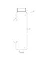
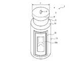
- the medical connector 1 as the present embodiment shown in FIG. 1has a housing 2, a valve 3, and an elastic member 4. Further, the medical connector 1 connects a medical device such as a medical tube and a syringe to each other to form a liquid feeding line formed between the medical device and the body cavity of a living body such as a human body. It has a male connector attachment / detachment portion 5 that can be connected.
- the housing 2has a male connector attachment / detachment portion 5 and forms a liquid flow path 6.
- the valve 3is pushed down by the male connector 7 (see FIG. 7) against the urging force from the closed position (see FIG. 1) that closes the male connector attachment / detachment portion 5 (that is, the male for convenience of explanation).
- the direction in which the connector 7 is pushed inis referred to as downward, and the opposite direction is referred to as upward), so that the housing 2 is located between the opening position (see FIG. 7) for communicating the flow path 8 in the male connector 7 with the liquid flow path 6.
- valve 3has a head portion 9 that closes the male connector attachment / detachment portion 5 in the closed state in the closed position, and a body portion 10 that is connected to the lower end of the head portion 9 and receives the urging force.
- the elastic member 4generates the urging force.
- the housing 2has a cylindrical male connector attachment / detachment portion 5 centered on an axis O extending in the vertical direction.
- a male connector 7configured as a lock-type male lure can be attached to and detached from the male connector attachment / detachment portion 5.
- the male connector attachment / detachment portion 5is configured to comply with, for example, ISO80369-7 of 2016.
- the direction along the straight line orthogonal to the axis Ois referred to as the radial direction
- the direction orbiting the axis Ois referred to as the circumferential direction.
- a conical diameter-expanding portion 11 that expands in diameter downwardis connected with the axis O as the center.
- a housing main body 12is connected to the lower end of the enlarged diameter portion 11.
- the housing main body 12forms a storage chamber 13 for accommodating the body 10 of the valve 3 so as to be able to move up and down.
- the storage chamber 13has a concave shape formed by a cylindrical inner peripheral surface centered on the axis O and a bottom surface.
- the housing main body 12forms a liquid flow path 6.
- the liquid flow path 6has a side opening 6a that opens to the side surface of the storage chamber 13 and a side flow path 6b that extends downward along the storage chamber 13 from the upper end communicating with the side opening 6a to the lower end below the storage chamber 13.
- the lower transverse flow path 6cextending radially inward from the lower end of the side flow path 6b to the lower part of the accommodation chamber 13, and the lower longitudinal flow path 6d extending downward coaxially with the axis O from the radial inner end of the lower transverse flow path 6c. And have.
- the lower member 2b forming the lower part of the housing main body 12forms a male connector configured as a lock type male lure having a lower end of the side flow path 6b, a lower horizontal flow path 6c, and a lower vertical flow path 6d inside. Therefore, the medical connector 1 is configured as an I-shaped connector.
- the male connector of the lower member 2bis configured to comply with, for example, the 2016 ISO 80369-7.
- the housing 2is formed by integrally connecting two parts, an upper member 2a and a lower member 2b, to each other by welding or the like.
- the lower member 2bmay form a medical device other than the male connector.
- the housing 2may be formed of one component or three or more components.
- the housing 2is made of a hard material such as synthetic resin.
- the valve 3has a head 9 made of an elastic material such as rubber or an elastomer, and for example polycarbonate, polypropylene, ABS (Acrylonitrile Butadiene Styrene), POM (PolyOxyMethylene). It has a body portion 10 made of a hard material such as synthetic resin such as.
- an elastic materialsuch as rubber or an elastomer, and for example polycarbonate, polypropylene, ABS (Acrylonitrile Butadiene Styrene), POM (PolyOxyMethylene).
- body portion 10made of a hard material such as synthetic resin such as.
- the head 9has a substantially cylindrical shape centered on the axis O.
- the head 9has a slit 14 that can be opened and closed.
- the slit 14is provided in the center of the head 9 in the top view, and forms a single character shape orthogonal to the axis O in the top view in the closed state. Both ends of the slit 14 in the length direction are separated from the outer peripheral edge of the head 9 at equal intervals in the top view.
- the slit 14penetrates the head 9 along the vertical direction.
- the upper part of the head portion 9has an elliptical shape in which the width Y in the direction perpendicular to the slit 14 is larger than the width X in the direction along the slit 14 in the natural state before the elastic deformation.
- the slit 14has an elongated elliptical shape when viewed from above. That is, the slit 14 opens in a natural state to form a flow path through which the liquid can pass.
- the head 9is pushed into the male connector attachment / detachment portion 5 which has a circular shape when viewed from above, the head 9 is compressed in the Y direction, whereby the slit 14 is closed.
- the shape of the upper part of the slit 14 and the head 9is not limited to the above. However, the shape of the upper part of the slit 14 and the head 9 is preferably a shape in which the slit 14 opens in a natural state and the head 9 is pushed into the male connector detachable portion 5 to close the slit 14.
- the body portion 10has a substantially columnar shape centered on the axis O, and has an upward convex portion 15 into which the lower end of the head portion 9 fits, and a shoulder portion 16 extending laterally from the lower end portion of the head portion 9.
- the upward convex portion 15projects from the upper surface of the body portion 10 and forms a substantially cylindrical shape centered on the axis O.
- the outer peripheral surface of the upward convex portion 15has an annular convex portion 15a centered on the axis O.
- the head portion 9has a recess 17 on the bottom surface having an inner peripheral surface having a complementary shape to the outer peripheral surface of the upward convex portion 15.
- the shoulder portion 16has a circular pyramidal shape with the axis O as the center and the diameter increases downward.
- the outer peripheral surface of the body portion 10 below the shoulder portion 16has a cylindrical surface shape.
- the shape of the shoulder portion 16is not limited to the conical surface shape, and can be appropriately changed according to the shape of the inner peripheral surface of the enlarged diameter portion 11 of the housing 2.
- the elastic member 4is composed of a coiled compression spring. As shown in FIG. 1, the elastic member 4 is arranged in the accommodation chamber 13 so as to be located between the bottom surface of the body portion 10 and the bottom surface of the accommodation chamber 13, and gives an upward urging force to the bottom surface of the body portion 10. ..
- the elastic member 4may be formed of a compression spring other than a coil shape such as a bellows shape.
- the elastic member 4is provided separately from the body portion 10. However, it may be integrally formed with the body portion 10, for example, by two-color molding.
- the elastic member 4is formed of, for example, a synthetic resin, rubber, an elastomer, a metal material such as stainless steel, or the like.
- the elastic member 4generates an urging force for returning the valve 3 from the open position to the closed position.
- a vent 18 leading to the outside of the medical connectoris provided on the side surface (outer peripheral surface) of the accommodation chamber 13. As the valve 3 descends, the air in the accommodating chamber 13 is discharged from the vent 18, while as the valve 3 rises, the air is introduced into the accommodating chamber 13 from the vent 18, so that the valve 3 moves up and down.
- the operationcan be smooth. However, the configuration may be such that the vent 18 is not provided.
- the lowering limit position of the valve 3is determined by the lower end (tip) position of the male connector 7 when the male connector 7 is fitted to the male connector attachment / detachment portion 5.
- the rising limit position of the valve 3is determined by the position where the shoulder portion 16 abuts on the lower surface (inner peripheral surface) of the enlarged diameter portion 11 of the housing 2.
- the valve 3passes through both the head portion 9 and the body portion 10, and in the open state where the valve 3 is in the open position, the flow path 8 in the male connector 7 becomes the liquid flow path 6. It has an internal flow path 19 for communication.
- the internal flow path 19is formed only by the inner surface of the valve 3.
- the internal flow path 19has an opening / closing end 19a that passes through the head 9 and opens as the valve 3 descends.
- the opening / closing end 19ais formed by a slit 14.
- the internal flow path 19has a side end 19b (see FIGS. 5 and 7) that opens to the side surface (outer peripheral surface) of the body portion 10.
- the body portion 10has a vertical flow path 19c extending vertically from the upper surface of the upward convex portion 15 in the center of the upper surface view of the body portion 10 and a horizontal flow path 19d extending from the lower end of the vertical flow path 19c to the side end 19b. And have.
- the internal flow path 19includes an opening / closing end 19a formed by the slit 14, a gap 19e between the upper surface of the upward convex portion and the lower surface of the head 9, a vertical flow path 19c, a horizontal flow path 19d, and a side end 19b. And consists of.
- the side end 19bfaces the side opening 6a of the liquid flow path 6 in both the closed state (see FIG. 1) and the open state (see FIG. 7).
- the side end 19bmay be configured not to face the side opening 6a in the closed state (see FIG. 1) but to face the side opening 6a in the open state (see FIG. 7).
- the side end 19b and the side opening 6ado not face each other in the closed state, the pressure fluctuation due to the deformation of the valve 3 is confined in the internal flow path 19, and the pressure fluctuation of the liquid flow path 6 is unlikely to occur, so that it is neutral.
- the structurecan be made easier to realize.
- the body portion 10has a seal member 20 that surrounds the side end 19b.
- the seal member 20is integrally provided on the side surface of the body portion 10, and slides vertically on the side surface of the accommodating chamber 13 as the valve 3 moves up and down.
- the seal member 20can prevent the liquid in the internal flow path 19 and the liquid flow path 6 from leaking from the gap between the side surface of the accommodating chamber 13 and the side surface of the body portion 10.
- the Young's modulus (longitudinal elastic modulus) of the body 10is larger than that of the head 9. Therefore, according to the present embodiment, as shown in FIGS. 1 and 7, the liquid flow path (that is, the internal flow path 19 and the liquid flow path 6) in the medical connector 1 is in the open state and the closed state. It is possible to easily realize a structure in which the volume change is small, that is, a neutral structure in which bolus and backflow are less likely to occur by attaching / detaching the male connector 7. If the Young's modulus of the body portion 10 is larger than that of the head portion 9, the materials of the head portion 9 and the body portion 10 are not limited to those described above.
- the internal flow path 19is formed only by the inner surface of the valve 3, it is possible to further facilitate the realization of a neutral structure. In addition, it is possible to suppress the retention of liquid in the medical connector 1.
- the internal flow path 19has an opening / closing end 19a that passes through the head portion 9 and opens as the valve 3 descends, it is possible to further facilitate the realization of a neutral structure.
- the internal flow path 19has a side end 19b that opens to the side surface of the body portion 10, it is possible to further facilitate the realization of a neutral structure.
- the liquid flow path 6has a side opening 6a that opens on the side surface of the storage chamber 13 that houses the body portion 10 so as to be able to move up and down, and the side opening 6a has an internal flow at least in an open state. Since it faces the side end 19b of the road 19, it is possible to further facilitate the realization of a neutral structure.
- the body portion 10since the body portion 10 has an upward convex portion 15 to which the lower end of the head portion 9 fits, it is possible to easily realize a neutral structure with a simple structure.
- the medical connector 1since the medical connector 1 has the elastic member 4 that generates an urging force, it is possible to easily realize a neutral structure with a simple structure.
- the medical connector 1 as the second embodimentwill be illustrated and described.
- the medical connector 1 as the present embodiment shown in FIGS. 8 to 9only the upper portion of the side end 19b passes through the lower portion of the side end 19b that does not face the side opening 6a in the open state (see FIG. 9).
- the configurationis different from that of the first embodiment only in that it communicates with the opening / closing end 19a.
- the second embodimentin addition to the effect obtained in the first embodiment, it is possible to obtain the effect of suppressing the retention of the liquid in the internal flow path 19.
- the medical connector 1 as the third embodimentwill be illustrated and described with reference to FIGS. 10 to 11.
- the internal flow path 19includes two side ends 19b that open to the side surface of the body portion 10, and the liquid flow path 6 is a storage chamber 13.
- the configurationdiffers from that of the first embodiment in that it includes two side openings 6a that open on the side surface. Other configurations are the same as those of the first embodiment.
- One side end 19bfaces one side opening 6a in both the closed state and the open state.
- the other side end 19bfaces the other side opening 6a in both the closed state and the open state.
- the two side ends 19bare provided so as to face each other.
- the liquid flow path 6has one flow path extending from one side opening 6a and the other flow path extending from the other side opening 6a.
- the liquid flow path 6is provided in the housing main body 12 of the housing 2.
- the internal flow path 19has a vertical flow path 19c extending downward from the opening / closing end 19a and a horizontal flow path 19d extending from the lower end of the vertical flow path 19c to both sides.
- the lower surface of the transverse flow path 19dhas a convex shape formed by two inclined surfaces 21 that incline upward from the two side ends 19b toward the inside of the valve 3, respectively.
- the body portion 10has two sealing members 20 surrounding the two side ends 19b.
- One seal member 20surrounds one side end 19b and the other seal member 20 surrounds the other side end 19b.
- the following effectscan be obtained in addition to the effects obtained in the first embodiment.
- the internal flow path 19includes two side ends 19b, the liquid flow path 6 includes two side openings 6a, and one side end 19b is in either the closed state or the open state. Also faces one side opening 6a and the other side end 19b faces the other side opening 6a in both the closed and open states, so that the medical connector 1 can be realized as a connector for mixed injection. Can be done.
- the internal flow path 19has a vertical flow path 19c extending downward from the opening / closing end 19a and a horizontal flow path 19d extending from the lower end of the vertical flow path 19c to both sides, and the horizontal flow path 19d. Since the lower surface of the valve 3 has a convex shape formed by two inclined surfaces 21 that incline upward from the two side ends 19b toward the inside of the valve 3, the retention of the liquid in the internal flow path 19 is suppressed. be able to.
- the medical connector 1includes a housing 2 having a male connector attachment / detachment portion 5 and forming a liquid flow path 6, and is pushed down by a male connector 7 from a closed position and a closed position for closing the male connector attachment / detachment portion 5 against urging force. It has a valve 3 that can be raised and lowered with respect to the housing 2 between the open position that allows the flow path 8 in the male connector 7 to communicate with the liquid flow path 6, and the valve 3 is in the closed position. It has a head portion 9 that closes the male connector attachment / detachment portion 5 in the closed state, and a body portion 10 that is connected to the lower end of the head portion 9 and receives the urging force. As long as it is large, it can be changed in various ways.
- valve 3has an internal flow path 19 that allows the flow path 8 in the male connector 7 to communicate with the liquid flow path 6 in the open state in which the valve 3 passes through at least the body portion 10 and is in the open position.
- the internal flow path 19is formed only by the inner surface of the valve 3.
- the internal flow path 19preferably has an opening / closing end 19a that passes through the head 9 and opens as the valve 3 descends.
- the opening / closing end 19ais preferably formed by the slit 14.
- the internal flow path 19preferably has a side end 19b that opens to the side surface of the body portion 10.
- the liquid flow path 6has a side opening 6a that opens on the side surface of the storage chamber 13 that houses the body portion 10 so as to be able to move up and down, and the side opening 6a faces the side end 19b of the internal flow path 19 at least in an open state. It is preferable to do so.
- the upper portion of the side end 19bcommunicates with the opening / closing end 19a only through the lower portion of the side end 19b that does not face the side opening 6a in the open state.
- the internal flow path 19includes two side ends 19b that open to the side surface of the body portion 10, and the liquid flow path 6 includes two side openings 6a that open to the side surface of the storage chamber 13 that houses the body portion 10 so as to be able to move up and down.
- One side end 19bfaces one side opening 6a in both the closed and open states, and the other side end 19b faces the other side opening in both the closed and open states. It is preferable to face 6a.
- the two side ends 19bare provided in opposite directions to each other.
- the internal flow path 19has a vertical flow path 19c extending downward from the opening / closing end 19a and a horizontal flow path 19d extending from the lower end of the vertical flow path 19c to both sides, and the lower surface of the horizontal flow path 19d has two side ends. It is preferable to form a convex shape formed by two inclined surfaces 21 that incline upward from 19b toward the inside of the valve 3, respectively.
- the body portion 10preferably has a shoulder portion 16 extending laterally from the lower end of the head portion 9.
- the body portion 10preferably has an upward convex portion 15 to which the lower end of the head portion 9 fits.
- the medical connector 1preferably has an elastic member 4 that generates an urging force.
Landscapes
- Health & Medical Sciences (AREA)
- Heart & Thoracic Surgery (AREA)
- Pulmonology (AREA)
- Engineering & Computer Science (AREA)
- Anesthesiology (AREA)
- Biomedical Technology (AREA)
- Hematology (AREA)
- Life Sciences & Earth Sciences (AREA)
- Animal Behavior & Ethology (AREA)
- General Health & Medical Sciences (AREA)
- Public Health (AREA)
- Veterinary Medicine (AREA)
- Infusion, Injection, And Reservoir Apparatuses (AREA)
Abstract
Description
Translated fromJapanese本開示は、医療用コネクタに関する。This disclosure relates to medical connectors.
従来から、カテーテル、医療用チューブ、シリンジ等の医療器具を互いに接続して、人体などの生体の体腔との間に送液ラインを形成し、この送液ラインを通じて輸液、輸血、人工透析などの送液を行っている。Conventionally, medical devices such as catheters, medical tubes, and syringes are connected to each other to form a liquid delivery line between the body cavity of a living body such as the human body, and infusion, blood transfusion, artificial dialysis, etc. are performed through this liquid delivery line. We are sending liquid.
このような送液ラインなどを形成するために医療器具を接続する医療用コネクタとして、オスコネクタ着脱部を備えるとともに液体流路を形成するハウジングと、オスコネクタ着脱部を閉塞する閉位置と閉位置から付勢力に抗してオスコネクタにより押し下げられることでオスコネクタ内の流路を液体流路に連通させる開位置との間でハウジングに対して昇降可能な弁と、を有し、弁が、弁が閉位置にある閉状態においてオスコネクタ着脱部を閉塞する頭部と、頭部の下端に連なり前記付勢力を受ける胴部と、を有するものが知られている(例えば、特許文献1~2参照)。As a medical connector for connecting a medical instrument to form such a liquid feeding line, a housing having a male connector attachment / detachment portion and forming a liquid flow path, and a closed position and a closed position for closing the male connector attachment / detachment portion. The valve has a valve that can be raised and lowered with respect to the housing between the open position that allows the flow path in the male connector to communicate with the liquid flow path by being pushed down by the male connector against the urging force. It is known that the valve has a head that closes the male connector attachment / detachment portion in the closed state in the closed position, and a body portion that is connected to the lower end of the head and receives the urging force (for example, Patent Documents 1 to 1). 2).
医療用コネクタは、オスコネクタ着脱部に対するオスコネクタの着脱操作によってボーラスもバックフローも発生しにくいことが要求される。ボーラスとは、医療用コネクタ内の液体が医療用コネクタの外部に押し出されることを意味する。バックフローとは、医療用コネクタの外部の液体が医療用コネクタ内に引き込まれることを意味する。例えば、カテーテルの基端に設けられた医療用コネクタにおいては、バックフローにより体内からカテーテル内に引き込まれた血液が固まって血栓となり、ボーラスによりカテーテル内から体内に前記血栓が投与される虞がある。Medical connectors are required to be less prone to bolus and backflow due to the male connector attachment / detachment operation to the male connector attachment / detachment part. Bolus means that the liquid in the medical connector is pushed out of the medical connector. Backflow means that liquid outside the medical connector is drawn into the medical connector. For example, in a medical connector provided at the base end of a catheter, blood drawn from the body into the catheter by backflow may solidify into a thrombus, and the bolus may administer the thrombus from the inside of the catheter into the body. ..
しかし、特許文献1~2に記載されるような医療用コネクタは、胴部が、頭部と同材質で形成されることから、開位置において頭部と均等に圧縮され、そのため、上記要求に応える構造を実現しにくいという問題点があった。However, since the body of the medical connector as described in
そこで本開示は、オスコネクタの着脱操作によってボーラスもバックフローも発生しにくいニュートラルな構造を実現しやすい医療用コネクタを提供することを目的とする。Therefore, the purpose of this disclosure is to provide a medical connector that can easily realize a neutral structure in which bolus and backflow are less likely to occur by attaching / detaching a male connector.
本開示の一態様としての医療用コネクタは、オスコネクタ着脱部を備えるとともに液体流路を形成するハウジングと、前記オスコネクタ着脱部を閉塞する閉位置と前記閉位置から付勢力に抗してオスコネクタにより押し下げられることで前記オスコネクタ内の流路を前記液体流路に連通させる開位置との間で前記ハウジングに対して昇降可能な弁と、を有し、前記弁が、前記弁が前記閉位置にある閉状態において前記オスコネクタ着脱部を閉塞する頭部と、前記頭部の下端に連なり前記付勢力を受ける胴部と、を有し、前記胴部のヤング率が前記頭部よりも大きい。The medical connector as one aspect of the present disclosure includes a housing having a male connector attachment / detachment portion and forming a liquid flow path, a closed position for closing the male connector attachment / detachment portion, and a male against urging force from the closed position. It has a valve that can be raised and lowered with respect to the housing between the open position that allows the flow path in the male connector to communicate with the liquid flow path by being pushed down by the connector, and the valve is the valve. It has a head that closes the male connector attachment / detachment portion in a closed position and a body portion that is connected to the lower end of the head portion and receives the urging force, and the young ratio of the body portion is higher than that of the head portion. Is also big.
本開示の一実施形態として、前記弁は、少なくとも前記胴部を通り、前記弁が前記開位置にある開状態において前記オスコネクタ内の前記流路を前記液体流路に連通させる内部流路を有する。As an embodiment of the present disclosure, the valve has an internal flow path that allows the flow path in the male connector to communicate with the liquid flow path in an open state in which the valve passes through at least the body portion and is in the open position. Have.
本開示の一実施形態として、前記内部流路は、前記弁の内面のみによって形成される。As one embodiment of the present disclosure, the internal flow path is formed only by the inner surface of the valve.
本開示の一実施形態として、前記内部流路は、前記頭部を通り前記弁の下降に伴って開く開閉端を有する。As one embodiment of the present disclosure, the internal flow path has an opening / closing end that passes through the head and opens as the valve descends.
本開示の一実施形態として、前記開閉端は、スリットで形成される。As one embodiment of the present disclosure, the opening / closing end is formed by a slit.
本開示の一実施形態として、前記内部流路は、前記胴部の側面に開口する側端を有する。As one embodiment of the present disclosure, the internal flow path has a side end that opens to the side surface of the body.
本開示の一実施形態として、前記液体流路は、前記胴部を昇降可能に収容する収容室の側面に開口する側口を有し、前記側口は、少なくとも前記開状態において、前記内部流路の前記側端に対向する。As one embodiment of the present disclosure, the liquid flow path has a side opening that opens to the side surface of a storage chamber that accommodates the body portion so as to be able to move up and down, and the side opening has the internal flow at least in the open state. Facing the side edge of the road.
本開示の一実施形態として、前記側端の上部は、前記開状態において、前記側口に対向しない前記側端の下部を介すことのみによって前記開閉端に連通する。As one embodiment of the present disclosure, the upper portion of the side end communicates with the open / closed end only through the lower portion of the side end that does not face the side opening in the open state.
本開示の一実施形態として、前記内部流路は、前記胴部の側面に開口する2つの側端を含み、前記液体流路は、前記胴部を昇降可能に収容する収容室の側面に開口する2つの側口を含み、一方の前記側端は、前記閉状態と前記開状態とのいずれにおいても一方の前記側口に対向し、他方の前記側端は、前記閉状態と前記開状態とのいずれにおいても他方の前記側口に対向する。As an embodiment of the present disclosure, the internal flow path includes two side ends that open to the sides of the body, and the liquid flow path opens to the side of a containment chamber that accommodates the body in an ascending / descending manner. One of the side ends faces the one side opening in both the closed and open states, and the other side end faces the closed and open states. In either case, it faces the other side opening.
本開示の一実施形態として、前記2つの側端は、互いに反対向きに設けられる。As one embodiment of the present disclosure, the two side ends are provided so as to face each other.
本開示の一実施形態として、前記内部流路は、前記開閉端から下方に延びる縦流路と、前記縦流路の下端から両側方に延びる横流路と、を有し、前記横流路の下面は、前記2つの側端からそれぞれ前記弁の内方に向かって上方に傾く2つの傾斜面で形成される凸状をなす。As one embodiment of the present disclosure, the internal flow path has a vertical flow path extending downward from the opening / closing end and a horizontal flow path extending from the lower end of the vertical flow path to both sides, and has a lower surface of the horizontal flow path. Form a convex shape formed by two inclined surfaces that incline upward from the two side ends toward the inside of the valve, respectively.
本開示の一実施形態として、前記胴部は、前記頭部の下端から側方に延びる肩部を有する。As one embodiment of the present disclosure, the body has a shoulder extending laterally from the lower end of the head.
本開示の一実施形態として、前記胴部は、前記頭部の下端が嵌合する上向き凸部を有する。As one embodiment of the present disclosure, the body portion has an upward convex portion into which the lower end of the head portion fits.
本開示の一実施形態として、前記付勢力を生じる弾性部材を有する。As one embodiment of the present disclosure, it has an elastic member that generates the urging force.
本開示によれば、オスコネクタの着脱操作によってボーラスもバックフローも発生しにくいニュートラルな構造を実現しやすい医療用コネクタを提供することができる。According to the present disclosure, it is possible to provide a medical connector that can easily realize a neutral structure in which bolus and backflow are less likely to occur by attaching / detaching a male connector.
以下、図面を参照して、本開示の実施形態について詳細に例示説明する。なお、各図において対応する要素に同一の符号を付す。Hereinafter, embodiments of the present disclosure will be illustrated in detail with reference to the drawings. The same reference numerals are given to the corresponding elements in each figure.
まず、図1~図7を参照して、第1実施形態としての医療用コネクタ1について例示説明する。図1に示す本実施形態としての医療用コネクタ1は、ハウジング2、弁3及び弾性部材4を有する。また、医療用コネクタ1は、医療用チューブ、シリンジ等の医療器具を互いに接続することで、人体などの生体の体腔との間に形成される送液ラインなどを形成するために、医療器具を接続することができるオスコネクタ着脱部5を有する。First, the medical connector 1 as the first embodiment will be illustrated and described with reference to FIGS. 1 to 7. The medical connector 1 as the present embodiment shown in FIG. 1 has a
ハウジング2は、オスコネクタ着脱部5を有するとともに液体流路6を形成する。弁3は、オスコネクタ着脱部5を閉塞する閉位置(図1参照)と閉位置から付勢力に抗してオスコネクタ7(図7参照)により押し下げられる(つまり、説明の便宜のため、オスコネクタ7により押し込まれる方向を下方と称し、その反対方向を上方と称する)ことでオスコネクタ7内の流路8を液体流路6に連通させる開位置(図7参照)との間でハウジング2に対して昇降可能である。また、弁3は、閉位置にある閉状態においてオスコネクタ着脱部5を閉塞する頭部9と、頭部9の下端に連なり前記付勢力を受ける胴部10と、を有する。弾性部材4は、前記付勢力を生じる。The
図1~図3に示すように、ハウジング2は、上下方向に沿って延びる軸線Oを中心とする円筒状のオスコネクタ着脱部5を有する。オスコネクタ着脱部5には、ロック式オスルアーとして構成されるオスコネクタ7を着脱可能である。オスコネクタ着脱部5は、例えば、2016年のISO80369-7に準拠するように構成される。As shown in FIGS. 1 to 3, the
以下の説明において、軸線Oに直交する直線に沿う方向を径方向といい、軸線Oを周回する方向を周方向という。In the following description, the direction along the straight line orthogonal to the axis O is referred to as the radial direction, and the direction orbiting the axis O is referred to as the circumferential direction.
オスコネクタ着脱部5の下端には、軸線Oを中心とし、下方に向けて拡径する円錐面状の拡径部11が連なる。拡径部11の下端には、ハウジング本体部12が連なる。ハウジング本体部12は、弁3の胴部10を昇降可能に収容する収容室13を形成する。収容室13は、軸線Oを中心とする円筒面状の内周面と、底面と、で形成される凹状をなす。At the lower end of the male connector attachment /
図1に示すように、ハウジング本体部12は、液体流路6を形成する。液体流路6は、収容室13の側面に開口する側口6aと、側口6aに連通する上端から収容室13よりも下方の下端まで収容室13に沿って下方に延びる側部流路6bと、側部流路6bの下端から収容室13の下方まで径方向内側に延びる下部横流路6cと、下部横流路6cの径方向内側端から軸線Oと同軸に下方に延びる下部縦流路6dと、を有する。As shown in FIG. 1, the housing
ハウジング本体部12の下部を形成する下部部材2bは、側部流路6bの下端と下部横流路6cと下部縦流路6dとを内部に有するロック式オスルアーとして構成されるオスコネクタを形成する。したがって、医療用コネクタ1は、I字型コネクタとして構成される。下部部材2bのオスコネクタは、例えば、2016年のISO80369-7に準拠するように構成される。ハウジング2は、図2に示すように上部部材2aと下部部材2bとの2部品を相互に溶着などによって一体に連結することで形成される。下部部材2bは、オスコネクタ以外の医療器具を形成してもよい。ハウジング2は1部品で形成してもよいし、3部品以上で形成してもよい。ハウジング2は合成樹脂などの硬質材料で形成される。The
図1、図4及び図5に示すように、弁3は、例えばゴム又はエラストマーなどの弾性材料で形成される頭部9と、例えばポリカーボネート、ポリプロピレン、ABS(Acrylonitrile Butadiene Styrene)、POM(PolyOxyMethylene)などの合成樹脂などの硬質材料で形成される胴部10と、を有する。As shown in FIGS. 1, 4 and 5, the
頭部9は、軸線Oを中心とする略円柱状をなす。頭部9は、開閉可能なスリット14を有する。スリット14は、上面視で頭部9の中央に設けられ、閉じた状態で上面視で軸線Oに直交する一文字状をなす。スリット14は、上面視で、長さ方向の両端が頭部9の外周縁から等間隔で離間する。スリット14は、頭部9を上下方向に沿って貫通する。頭部9の上部は、弾性変形する前の自然状態において、上面視で、スリット14に垂直な方向の幅Yがスリット14に沿う方向の幅Xよりも大きい楕円形状をなす。また、スリット14は、自然状態において、上面視で細長い楕円形状をなす。つまり、スリット14は自然状態では開き、液体が通過できる流路を形成する。頭部9が上面視で円形状をなすオスコネクタ着脱部5内に押し込まれることで、頭部9はY方向に圧縮され、それによりスリット14が閉じる。The
なお、スリット14及び頭部9の上部の形状は上記に限定されない。しかし、スリット14及び頭部9の上部の形状は、自然状態においてスリット14が開き、頭部9がオスコネクタ脱着部5内に押し込まれることでスリット14が閉じる形状であることが好ましい。The shape of the upper part of the
胴部10は、軸線Oを中心とする略円柱状をなし、頭部9の下端が嵌合する上向き凸部15と、頭部9の下端から側方に延びる肩部16と、を有する。上向き凸部15は、胴部10の上面から突出し、軸線Oを中心とする略円柱状をなす。上向き凸部15の外周面は、軸線Oを中心とする円環状の凸部15aを有する。頭部9は、上向き凸部15の外周面に対する相補形状の内周面を有する凹部17を底面に有する。頭部9の凹部17が上向き凸部15に嵌合することで、頭部9が胴部10に保持される。肩部16は、軸線Oを中心とし、下方に向けて拡径する円錘面状をなす。胴部10の肩部16よりも下方における外周面は、円筒面状をなす。The
なお、肩部16の形状は円錐面状に限定されず、ハウジング2の拡径部11の内周面の形状に応じて適宜変更可能である。The shape of the
図6に示すように、弾性部材4は、コイル状の圧縮ばねで構成される。図1に示すように、弾性部材4は収容室13内に胴部10の底面と収容室13の底面との間に位置するように配置され、胴部10の底面に上向きの付勢力を与える。弾性部材4は、蛇腹状など、コイル状以外の圧縮ばねで構成してもよい。弾性部材4は胴部10とは別体に設けられる。しかし、例えば二色成形などにより、胴部10と一体に形成してもよい。弾性部材4は、例えば合成樹脂、ゴム、エラストマー又はステンレス等の金属材料などで形成される。As shown in FIG. 6, the
図1及び図7に示すように、弾性部材4は、弁3を開位置から閉位置に復帰させる付勢力を生じる。収容室13の側面(外周面)には、医療用コネクタの外部に通じる通気口18が設けられる。弁3の下降に伴って収容室13内の空気が通気口18から排出される一方、弁3の上昇に伴って収容室13内に空気が通気口18から導入されるので、弁3の昇降動作をスムーズにすることができる。しかし、通気口18を設けない構成としてもよい。As shown in FIGS. 1 and 7, the
弁3が下降する時、弁3の下降限界位置は、オスコネクタ7がオスコネクタ着脱部5に嵌合した時のオスコネクタ7の下端(先端)位置によって決まる。弁3が上昇する時、弁3の上昇限界位置は、肩部16がハウジング2の拡径部11の下面(内周面)に当接する位置によって決まる。When the
図1及び図7に示すように、弁3は、頭部9と胴部10をいずれも通り、弁3が開位置にある開状態においてオスコネクタ7内の流路8を液体流路6に連通させる内部流路19を有する。内部流路19は、弁3の内面のみによって形成される。内部流路19は、頭部9を通り弁3の下降に伴って開く開閉端19aを有する。開閉端19aはスリット14で形成される。内部流路19は、胴部10の側面(外周面)に開口する側端19b(図5及び図7参照)を有する。As shown in FIGS. 1 and 7, the
胴部10は、胴部10の上面視の中央を上向き凸部15の上面から下方に上下方向に沿って延びる縦流路19cと、縦流路19cの下端から側端19bまで延びる横流路19dと、を有する。内部流路19は、スリット14で形成される開閉端19aと、上向き凸部の上面と頭部9の下面との間の隙間19eと、縦流路19cと、横流路19dと、側端19bと、で構成される。The
側端19bは、閉状態(図1参照)と開状態(図7参照)とのいずれにおいても、液体流路6の側口6aに対向する。なお、側端19bは、閉状態(図1参照)では側口6aと対向せずに、開状態(図7参照)では側口6aに対向する構成としてもよい。閉状態において側端19bと側口6aが対向しない構成とする場合、弁3の変形による圧力変動が内部流路19に閉じ込められて、液体流路6の圧力変動が発生し難いため、ニュートラルな構造をより一層実現しやすくすることができる。The
図1、図5及び図7に示すように、胴部10は、側端19bを包囲するシール部材20を有する。シール部材20は、胴部10の側面に一体に設けられ、収容室13の側面上を弁3の昇降に伴って上下方向に摺動する。シール部材20は、内部流路19及び液体流路6内の液体が収容室13の側面と胴部10の側面との隙間から漏出することを抑制することができる。As shown in FIGS. 1, 5 and 7, the
本実施形態では、胴部10のヤング率(縦弾性係数)は頭部9よりも大きい。したがって、本実施形態によれば、図1及び図7に示すように、開状態と閉状態とで医療用コネクタ1内の液体の流路(つまり、内部流路19と液体流路6)の容積変化が少なくい構造、すなわち、オスコネクタ7の着脱操作によってボーラスもバックフローも発生しにくいニュートラルな構造を実現しやすくすることができる。なお、胴部10のヤング率が頭部9よりも大きければ、頭部9及び胴部10の材質は上述したものに限らない。In this embodiment, the Young's modulus (longitudinal elastic modulus) of the
また、本実施形態によれば、弁3が、少なくとも胴部10を通り開状態においてオスコネクタ7内の流路8を液体流路6に連通させる内部流路19を有するので、ニュートラルな構造をより一層実現しやすくすることができる。Further, according to the present embodiment, since the
また、本実施形態によれば、内部流路19が弁3の内面のみによって形成されるので、ニュートラルな構造をより一層実現しやすくすることができる。また、医療用コネクタ1内での液体の滞留を抑制することができる。Further, according to the present embodiment, since the
また、本実施形態によれば、内部流路19が、頭部9を通り弁3の下降に伴って開く開閉端19aを有するので、ニュートラルな構造をより一層実現しやすくすることができる。Further, according to the present embodiment, since the
また、本実施形態によれば、開閉端19aがスリット14で形成されるので、ニュートラルな構造をより一層実現しやすくすることができる。Further, according to the present embodiment, since the opening / closing
また、本実施形態によれば、内部流路19が胴部10の側面に開口する側端19bを有するので、ニュートラルな構造をより一層実現しやすくすることができる。Further, according to the present embodiment, since the
また、本実施形態によれば、液体流路6が、胴部10を昇降可能に収容する収容室13の側面に開口する側口6aを有し、側口6aが、少なくとも開状態において内部流路19の側端19bに対向するので、ニュートラルな構造をより一層実現しやすくすることができる。Further, according to the present embodiment, the
また、本実施形態によれば、胴部10が、頭部9の下端から側方に延びる肩部16を有するので、ニュートラルな構造を簡単な構造で実現しやすくすることができる。Further, according to the present embodiment, since the
また、本実施形態によれば、胴部10が、頭部9の下端が嵌合する上向き凸部15を有するので、ニュートラルな構造を簡単な構造で実現しやすくすることができる。Further, according to the present embodiment, since the
また、本実施形態によれば、医療用コネクタ1が、付勢力を生じる弾性部材4を有するので、ニュートラルな構造を簡単な構造で実現しやすくすることができる。Further, according to the present embodiment, since the medical connector 1 has the
次に、図8~図9を参照して、第2実施形態としての医療用コネクタ1について例示説明する。図8~図9に示す本実施形態としての医療用コネクタ1は、側端19bの上部が、開状態(図9参照)において、側口6aに対向しない側端19bの下部を介すことのみによって開閉端19aに連通する点のみにおいて、第1実施形態と構成が相違する。第2実施形態によれば、第1実施形態で得られる効果に加えて、内部流路19内での液体の滞留を抑制することできるという効果も得ることができる。Next, with reference to FIGS. 8 to 9, the medical connector 1 as the second embodiment will be illustrated and described. In the medical connector 1 as the present embodiment shown in FIGS. 8 to 9, only the upper portion of the
次に、図10~図11を参照して、第3実施形態としての医療用コネクタ1について例示説明する。図10~図11に示す本実施形態としての医療用コネクタ1は、内部流路19が、胴部10の側面に開口する2つの側端19bを含み、液体流路6が、収容室13の側面に開口する2つの側口6aを含む点で、第1実施形態と構成が相違する。その他の構成は第1実施形態と同様である。Next, the medical connector 1 as the third embodiment will be illustrated and described with reference to FIGS. 10 to 11. In the medical connector 1 as the present embodiment shown in FIGS. 10 to 11, the
一方の側端19bは、閉状態と開状態とのいずれにおいても一方の側口6aに対向する。他方の側端19bは、閉状態と開状態とのいずれにおいても他方の側口6aに対向する。2つの側端19bは、互いに反対向きに設けられる。One
液体流路6は、一方の側口6aから延びる一方の流路と、他方の側口6aから延びる他方の流路と、を有する。液体流路6は、ハウジング2のハウジング本体部12に設けられる。The
内部流路19は、開閉端19aから下方に延びる縦流路19cと、縦流路19cの下端から両側方に延びる横流路19dと、を有する。横流路19dの下面は、2つの側端19bからそれぞれ弁3の内方に向かって上方に傾く2つの傾斜面21で形成される凸状をなす。The
胴部10は、2つの側端19bを包囲する2つのシール部材20を有する。一方のシール部材20は、一方の側端19bを包囲し、他方のシール部材20は、他方の側端19bを包囲する。The
第3実施形態によれば、第1実施形態で得られる効果に加えて、以下の効果も得ることができる。According to the third embodiment, the following effects can be obtained in addition to the effects obtained in the first embodiment.
第3実施形態によれば、内部流路19が2つの側端19bを含み、液体流路6が2つの側口6aを含み、一方の側端19bが、閉状態と開状態とのいずれにおいても一方の側口6aに対向し、他方の側端19bが、閉状態と開状態とのいずれにおいても他方の側口6aに対向するので、医療用コネクタ1を混注用のコネクタとして実現することができる。According to the third embodiment, the
第3実施形態によれば、2つの側端19bが互いに反対向きに設けられる医療用コネクタ1をT字型コネクタ又はY字型コネクタとして実現することができる。According to the third embodiment, the medical connector 1 in which the two side ends 19b are provided in opposite directions can be realized as a T-shaped connector or a Y-shaped connector.
第3実施形態によれば、内部流路19が、開閉端19aから下方に延びる縦流路19cと、縦流路19cの下端から両側方に延びる横流路19dと、を有し、横流路19dの下面が、2つの側端19bからそれぞれ弁3の内方に向かって上方に傾く2つの傾斜面21で形成される凸状をなすので、内部流路19内での液体の滞留を抑制することができる。According to the third embodiment, the
前述した実施形態は本開示の一例にすぎず、例えば以下に述べるような種々の変更が可能である。The above-mentioned embodiment is only an example of the present disclosure, and various changes as described below are possible, for example.
医療用コネクタ1は、オスコネクタ着脱部5を備えるとともに液体流路6を形成するハウジング2と、オスコネクタ着脱部5を閉塞する閉位置と閉位置から付勢力に抗してオスコネクタ7により押し下げられることでオスコネクタ7内の流路8を液体流路6に連通させる開位置との間でハウジング2に対して昇降可能な弁3と、を有し、弁3が、弁3が閉位置にある閉状態においてオスコネクタ着脱部5を閉塞する頭部9と、頭部9の下端に連なり前記付勢力を受ける胴部10と、を有し、胴部10のヤング率が頭部9よりも大きい限り、種々変更可能である。The medical connector 1 includes a
しかし、弁3は、少なくとも胴部10を通り、弁3が開位置にある開状態においてオスコネクタ7内の流路8を液体流路6に連通させる内部流路19を有することが好ましい。However, it is preferable that the
また、内部流路19は、弁3の内面のみによって形成されることが好ましい。Further, it is preferable that the
内部流路19は、頭部9を通り弁3の下降に伴って開く開閉端19aを有することが好ましい。The
開閉端19aは、スリット14で形成されることが好ましい。The opening / closing
内部流路19は、胴部10の側面に開口する側端19bを有することが好ましい。The
液体流路6は、胴部10を昇降可能に収容する収容室13の側面に開口する側口6aを有し、側口6aは、少なくとも開状態において、内部流路19の側端19bに対向することが好ましい。The
側端19bの上部は、開状態において、側口6aに対向しない側端19bの下部を介すことのみによって開閉端19aに連通することが好ましい。It is preferable that the upper portion of the
内部流路19は、胴部10の側面に開口する2つの側端19bを含み、液体流路6は、胴部10を昇降可能に収容する収容室13の側面に開口する2つの側口6aを含み、一方の側端19bは、閉状態と開状態とのいずれにおいても一方の側口6aに対向し、他方の側端19bは、閉状態と開状態とのいずれにおいても他方の側口6aに対向することが好ましい。The
2つの側端19bは、互いに反対向きに設けられることが好ましい。It is preferable that the two side ends 19b are provided in opposite directions to each other.
内部流路19は、開閉端19aから下方に延びる縦流路19cと、縦流路19cの下端から両側方に延びる横流路19dと、を有し、横流路19dの下面は、2つの側端19bからそれぞれ弁3の内方に向かって上方に傾く2つの傾斜面21で形成される凸状をなすことが好ましい。The
胴部10は、頭部9の下端から側方に延びる肩部16を有することが好ましい。The
胴部10は、頭部9の下端が嵌合する上向き凸部15を有することが好ましい。The
医療用コネクタ1は、付勢力を生じる弾性部材4を有することが好ましい。The medical connector 1 preferably has an
1 医療用コネクタ
2 ハウジング
2a 上部部材
2b 下部部材
3 弁
4 弾性部材
5 オスコネクタ着脱部
6 液体流路
6a 側口
6b 側部流路
6c 下部横流路
6d 下部縦流路
7 オスコネクタ
8 オスコネクタ内の流路
9 頭部
10 胴部
11 拡径部
12 ハウジング本体部
13 収容室
14 スリット
15 上向き凸部
15a 凸部
16 肩部
17 凹部
18 通気口
19 内部流路
19a 開閉端
19b 側端
19c 縦流路
19d 横流路
19e 隙間
20 シール部材
21 傾斜面1
Claims (14)
Translated fromJapanese前記オスコネクタ着脱部を閉塞する閉位置と前記閉位置から付勢力に抗してオスコネクタにより押し下げられることで前記オスコネクタ内の流路を前記液体流路に連通させる開位置との間で前記ハウジングに対して昇降可能な弁と、を有し、
前記弁が、前記弁が前記閉位置にある閉状態において前記オスコネクタ着脱部を閉塞する頭部と、前記頭部の下端に連なり前記付勢力を受ける胴部と、を有し、
前記胴部のヤング率が前記頭部よりも大きい、
医療用コネクタ。A housing that has a male connector attachment / detachment part and forms a liquid flow path,
The closed position that closes the male connector attachment / detachment portion and the open position that allows the flow path in the male connector to communicate with the liquid flow path by being pushed down by the male connector against the urging force from the closed position. With a valve that can be raised and lowered with respect to the housing,
The valve has a head that closes the male connector attachment / detachment portion in the closed state in which the valve is in the closed position, and a body portion that is connected to the lower end of the head and receives the urging force.
The Young's modulus of the body is larger than that of the head.
Medical connector.
前記側口は、少なくとも前記開状態において、前記内部流路の前記側端に対向する、請求項6に記載の医療用コネクタ。The liquid flow path has a side opening that opens to the side surface of a storage chamber that houses the body portion so as to be able to move up and down.
The medical connector according to claim 6, wherein the side opening faces the side end of the internal flow path at least in the open state.
前記液体流路は、前記胴部を昇降可能に収容する収容室の側面に開口する2つの側口を含み、
一方の前記側端は、前記閉状態と前記開状態とのいずれにおいても一方の前記側口に対向し、
他方の前記側端は、前記閉状態と前記開状態とのいずれにおいても他方の前記側口に対向する、請求項2~5の何れか1項に記載の医療用コネクタ。The internal flow path includes two side ends that open to the sides of the body.
The liquid flow path includes two side openings that open to the sides of a containment chamber that accommodates the body in an ascending / descending manner.
One of the side ends faces one of the side openings in both the closed and open states.
The medical connector according to any one of claims 2 to 5, wherein the other side end faces the other side opening in both the closed state and the open state.
前記横流路の下面は、前記2つの側端からそれぞれ前記弁の内方に向かって上方に傾く2つの傾斜面で形成される凸状をなす、請求項10に記載の医療用コネクタ。The internal flow path has a vertical flow path extending downward from the opening / closing end and a horizontal flow path extending from the lower end of the vertical flow path to both sides.
The medical connector according to claim 10, wherein the lower surface of the transverse flow path has a convex shape formed by two inclined surfaces that incline upward from the two side ends toward the inside of the valve, respectively.
Priority Applications (2)
| Application Number | Priority Date | Filing Date | Title |
|---|---|---|---|
| JP2022561332AJPWO2022102300A1 (en) | 2020-11-12 | 2021-10-07 | |
| US18/195,300US12144957B2 (en) | 2020-11-12 | 2023-05-09 | Medical connector |
Applications Claiming Priority (2)
| Application Number | Priority Date | Filing Date | Title |
|---|---|---|---|
| JP2020188903 | 2020-11-12 | ||
| JP2020-188903 | 2020-11-12 |
Related Child Applications (1)
| Application Number | Title | Priority Date | Filing Date |
|---|---|---|---|
| US18/195,300ContinuationUS12144957B2 (en) | 2020-11-12 | 2023-05-09 | Medical connector |
Publications (1)
| Publication Number | Publication Date |
|---|---|
| WO2022102300A1true WO2022102300A1 (en) | 2022-05-19 |
Family
ID=81600942
Family Applications (1)
| Application Number | Title | Priority Date | Filing Date |
|---|---|---|---|
| PCT/JP2021/037208CeasedWO2022102300A1 (en) | 2020-11-12 | 2021-10-07 | Medical connector |
Country Status (3)
| Country | Link |
|---|---|
| US (1) | US12144957B2 (en) |
| JP (1) | JPWO2022102300A1 (en) |
| WO (1) | WO2022102300A1 (en) |
Families Citing this family (1)
| Publication number | Priority date | Publication date | Assignee | Title |
|---|---|---|---|---|
| US12268837B2 (en)* | 2022-12-28 | 2025-04-08 | Carefusion 303, Inc. | Neutral displacement connector |
Citations (2)
| Publication number | Priority date | Publication date | Assignee | Title |
|---|---|---|---|---|
| JP2001506156A (en)* | 1996-12-16 | 2001-05-15 | アイシーユー メディカル、インコーポレイテッド | Positive flow valve |
| US20200129750A1 (en)* | 2018-10-25 | 2020-04-30 | Tai-Yi CHEN | Needle-free connector |
Family Cites Families (24)
| Publication number | Priority date | Publication date | Assignee | Title |
|---|---|---|---|---|
| US5163922A (en)* | 1991-04-29 | 1992-11-17 | Charles E. McElveen, Jr. | Dual-valved connector for intravenous systems |
| NZ286445A (en)* | 1995-05-16 | 1997-12-19 | Ivac Corp | Needleless luer connector: deformable piston occludes bore |
| US5730418A (en)* | 1996-09-30 | 1998-03-24 | The Kipp Group | Minimum fluid displacement medical connector |
| PT952868E (en)* | 1996-11-18 | 2004-08-31 | Nypro Inc | VALVE CONICA-LUER LAVAVEL |
| IL127900A (en)* | 1999-01-01 | 2001-12-23 | Elcam Plastic Kibbutz Bar Am | Blood sampling/injecting valve |
| US6228069B1 (en)* | 1999-04-05 | 2001-05-08 | Filtertek Inc. | Needleless access device |
| WO2003018104A2 (en)* | 2001-08-22 | 2003-03-06 | Nypro, Inc. | Medical valve with expandable seal member |
| US7037302B2 (en)* | 2001-09-07 | 2006-05-02 | Patricia B. Vaillancourt, legal representative | Positive flow needleless connector |
| JP4116785B2 (en)* | 2001-11-14 | 2008-07-09 | テルモ株式会社 | connector |
| WO2004112866A2 (en)* | 2003-06-17 | 2004-12-29 | Filtertek Inc. | Fluid handling device and method of making same |
| US7914502B2 (en)* | 2003-07-31 | 2011-03-29 | Nypro Inc. | Anti-drawback medical valve |
| US7645274B2 (en)* | 2004-12-10 | 2010-01-12 | Cardinal Health 303, Inc. | Self-sealing male luer connector with multiple seats |
| BRPI0717401A2 (en)* | 2006-10-25 | 2013-11-12 | Icu Medical Inc | CONNECTOR FOR MEDICAL USE |
| JP2012024565A (en)* | 2010-06-23 | 2012-02-09 | Top Corp | Connector |
| US9107987B2 (en)* | 2011-08-08 | 2015-08-18 | Pacific Hospital Supply Co., Ltd. | Irrigator port for phlegm suction tube |
| EP3124073B1 (en)* | 2014-03-28 | 2019-01-30 | Terumo Kabushiki Kaisha | Medical connector |
| JP6654140B2 (en)* | 2014-09-24 | 2020-02-26 | テルモ株式会社 | Medical connector |
| JP6776225B2 (en)* | 2015-03-27 | 2020-10-28 | テルモ株式会社 | Medical connector |
| WO2016157886A1 (en)* | 2015-03-30 | 2016-10-06 | テルモ株式会社 | Medical connector |
| WO2017222080A1 (en)* | 2016-06-24 | 2017-12-28 | テルモ株式会社 | Connector |
| TWI623333B (en)* | 2016-11-21 | 2018-05-11 | Medical infusion connector | |
| JP2021521967A (en)* | 2018-04-24 | 2021-08-30 | ケアフュージョン 303、インコーポレイテッド | Self flushing connector |
| JP7167408B2 (en)* | 2019-01-28 | 2022-11-09 | 株式会社トップ | connector |
| WO2020158580A1 (en)* | 2019-01-28 | 2020-08-06 | 株式会社トップ | Connector |
- 2021
- 2021-10-07JPJP2022561332Apatent/JPWO2022102300A1/jaactivePending
- 2021-10-07WOPCT/JP2021/037208patent/WO2022102300A1/ennot_activeCeased
- 2023
- 2023-05-09USUS18/195,300patent/US12144957B2/enactiveActive
Patent Citations (2)
| Publication number | Priority date | Publication date | Assignee | Title |
|---|---|---|---|---|
| JP2001506156A (en)* | 1996-12-16 | 2001-05-15 | アイシーユー メディカル、インコーポレイテッド | Positive flow valve |
| US20200129750A1 (en)* | 2018-10-25 | 2020-04-30 | Tai-Yi CHEN | Needle-free connector |
Also Published As
| Publication number | Publication date |
|---|---|
| US12144957B2 (en) | 2024-11-19 |
| US20230277835A1 (en) | 2023-09-07 |
| JPWO2022102300A1 (en) | 2022-05-19 |
Similar Documents
| Publication | Publication Date | Title |
|---|---|---|
| US10842984B2 (en) | Connector for transferring fluid | |
| US6068011A (en) | Control of fluid flow | |
| US10940306B2 (en) | Connector for transferring fluid and method of use | |
| US5699821A (en) | Control of fluid flow | |
| US8100866B2 (en) | Needleless access port valves | |
| CN104023786B (en) | Needleless connector | |
| JP4469802B2 (en) | Needleless connector valve | |
| EP2111888A2 (en) | Needleless luer access connector | |
| JP6059338B2 (en) | connector | |
| JP2007500572A (en) | Self-sealing male connector | |
| WO2022102300A1 (en) | Medical connector | |
| WO2013038619A1 (en) | Connector valve body and connector | |
| US10195417B2 (en) | Connecting element for providing fluidic connection between vessels | |
| WO2022102301A1 (en) | Medical connector | |
| JP6943195B2 (en) | Hub assembly and how to assemble the hub assembly | |
| JP6246306B2 (en) | connector | |
| JP2014050524A (en) | Connector valve element and connector | |
| JP2013044375A (en) | Connector | |
| JP2021045419A (en) | Medical connector | |
| MXPA97009871A (en) | Implement access device |
Legal Events
| Date | Code | Title | Description |
|---|---|---|---|
| 121 | Ep: the epo has been informed by wipo that ep was designated in this application | Ref document number:21891547 Country of ref document:EP Kind code of ref document:A1 | |
| ENP | Entry into the national phase | Ref document number:2022561332 Country of ref document:JP Kind code of ref document:A | |
| NENP | Non-entry into the national phase | Ref country code:DE | |
| 122 | Ep: pct application non-entry in european phase | Ref document number:21891547 Country of ref document:EP Kind code of ref document:A1 |