WO2022101953A1 - Suction device, information transmission method, and program - Google Patents
Suction device, information transmission method, and programDownload PDFInfo
- Publication number
- WO2022101953A1 WO2022101953A1PCT/JP2020/041794JP2020041794WWO2022101953A1WO 2022101953 A1WO2022101953 A1WO 2022101953A1JP 2020041794 WJP2020041794 WJP 2020041794WWO 2022101953 A1WO2022101953 A1WO 2022101953A1
- Authority
- WO
- WIPO (PCT)
- Prior art keywords
- information indicating
- time
- heating
- suction device
- heating unit
- Prior art date
- Legal status (The legal status is an assumption and is not a legal conclusion. Google has not performed a legal analysis and makes no representation as to the accuracy of the status listed.)
- Ceased
Links
Images


Classifications
- A—HUMAN NECESSITIES
- A24—TOBACCO; CIGARS; CIGARETTES; SIMULATED SMOKING DEVICES; SMOKERS' REQUISITES
- A24F—SMOKERS' REQUISITES; MATCH BOXES; SIMULATED SMOKING DEVICES
- A24F40/00—Electrically operated smoking devices; Component parts thereof; Manufacture thereof; Maintenance or testing thereof; Charging means specially adapted therefor
- A24F40/50—Control or monitoring
- G—PHYSICS
- G08—SIGNALLING
- G08C—TRANSMISSION SYSTEMS FOR MEASURED VALUES, CONTROL OR SIMILAR SIGNALS
- G08C17/00—Arrangements for transmitting signals characterised by the use of a wireless electrical link
- G08C17/02—Arrangements for transmitting signals characterised by the use of a wireless electrical link using a radio link
- A—HUMAN NECESSITIES
- A24—TOBACCO; CIGARS; CIGARETTES; SIMULATED SMOKING DEVICES; SMOKERS' REQUISITES
- A24F—SMOKERS' REQUISITES; MATCH BOXES; SIMULATED SMOKING DEVICES
- A24F40/00—Electrically operated smoking devices; Component parts thereof; Manufacture thereof; Maintenance or testing thereof; Charging means specially adapted therefor
- A24F40/30—Devices using two or more structurally separated inhalable precursors, e.g. using two liquid precursors in two cartridges
- A—HUMAN NECESSITIES
- A24—TOBACCO; CIGARS; CIGARETTES; SIMULATED SMOKING DEVICES; SMOKERS' REQUISITES
- A24F—SMOKERS' REQUISITES; MATCH BOXES; SIMULATED SMOKING DEVICES
- A24F40/00—Electrically operated smoking devices; Component parts thereof; Manufacture thereof; Maintenance or testing thereof; Charging means specially adapted therefor
- A24F40/40—Constructional details, e.g. connection of cartridges and battery parts
- A24F40/46—Shape or structure of electric heating means
- A—HUMAN NECESSITIES
- A24—TOBACCO; CIGARS; CIGARETTES; SIMULATED SMOKING DEVICES; SMOKERS' REQUISITES
- A24F—SMOKERS' REQUISITES; MATCH BOXES; SIMULATED SMOKING DEVICES
- A24F40/00—Electrically operated smoking devices; Component parts thereof; Manufacture thereof; Maintenance or testing thereof; Charging means specially adapted therefor
- A24F40/50—Control or monitoring
- A24F40/57—Temperature control
- A—HUMAN NECESSITIES
- A24—TOBACCO; CIGARS; CIGARETTES; SIMULATED SMOKING DEVICES; SMOKERS' REQUISITES
- A24F—SMOKERS' REQUISITES; MATCH BOXES; SIMULATED SMOKING DEVICES
- A24F40/00—Electrically operated smoking devices; Component parts thereof; Manufacture thereof; Maintenance or testing thereof; Charging means specially adapted therefor
- A24F40/65—Devices with integrated communication means, e.g. wireless communication means
- A—HUMAN NECESSITIES
- A61—MEDICAL OR VETERINARY SCIENCE; HYGIENE
- A61M—DEVICES FOR INTRODUCING MEDIA INTO, OR ONTO, THE BODY; DEVICES FOR TRANSDUCING BODY MEDIA OR FOR TAKING MEDIA FROM THE BODY; DEVICES FOR PRODUCING OR ENDING SLEEP OR STUPOR
- A61M11/00—Sprayers or atomisers specially adapted for therapeutic purposes
- A61M11/04—Sprayers or atomisers specially adapted for therapeutic purposes operated by the vapour pressure of the liquid to be sprayed or atomised
- A61M11/041—Sprayers or atomisers specially adapted for therapeutic purposes operated by the vapour pressure of the liquid to be sprayed or atomised using heaters
- A61M11/042—Sprayers or atomisers specially adapted for therapeutic purposes operated by the vapour pressure of the liquid to be sprayed or atomised using heaters electrical
- A—HUMAN NECESSITIES
- A61—MEDICAL OR VETERINARY SCIENCE; HYGIENE
- A61M—DEVICES FOR INTRODUCING MEDIA INTO, OR ONTO, THE BODY; DEVICES FOR TRANSDUCING BODY MEDIA OR FOR TAKING MEDIA FROM THE BODY; DEVICES FOR PRODUCING OR ENDING SLEEP OR STUPOR
- A61M15/00—Inhalators
- A61M15/06—Inhaling appliances shaped like cigars, cigarettes or pipes
- G—PHYSICS
- G06—COMPUTING OR CALCULATING; COUNTING
- G06F—ELECTRIC DIGITAL DATA PROCESSING
- G06F3/00—Input arrangements for transferring data to be processed into a form capable of being handled by the computer; Output arrangements for transferring data from processing unit to output unit, e.g. interface arrangements
- G06F3/01—Input arrangements or combined input and output arrangements for interaction between user and computer
- G06F3/048—Interaction techniques based on graphical user interfaces [GUI]
- G06F3/0484—Interaction techniques based on graphical user interfaces [GUI] for the control of specific functions or operations, e.g. selecting or manipulating an object, an image or a displayed text element, setting a parameter value or selecting a range
- G06F3/04847—Interaction techniques to control parameter settings, e.g. interaction with sliders or dials
- G—PHYSICS
- G06—COMPUTING OR CALCULATING; COUNTING
- G06F—ELECTRIC DIGITAL DATA PROCESSING
- G06F9/00—Arrangements for program control, e.g. control units
- G06F9/06—Arrangements for program control, e.g. control units using stored programs, i.e. using an internal store of processing equipment to receive or retain programs
- G06F9/44—Arrangements for executing specific programs
- G06F9/451—Execution arrangements for user interfaces
- A—HUMAN NECESSITIES
- A24—TOBACCO; CIGARS; CIGARETTES; SIMULATED SMOKING DEVICES; SMOKERS' REQUISITES
- A24F—SMOKERS' REQUISITES; MATCH BOXES; SIMULATED SMOKING DEVICES
- A24F40/00—Electrically operated smoking devices; Component parts thereof; Manufacture thereof; Maintenance or testing thereof; Charging means specially adapted therefor
- A24F40/10—Devices using liquid inhalable precursors
- A—HUMAN NECESSITIES
- A61—MEDICAL OR VETERINARY SCIENCE; HYGIENE
- A61M—DEVICES FOR INTRODUCING MEDIA INTO, OR ONTO, THE BODY; DEVICES FOR TRANSDUCING BODY MEDIA OR FOR TAKING MEDIA FROM THE BODY; DEVICES FOR PRODUCING OR ENDING SLEEP OR STUPOR
- A61M11/00—Sprayers or atomisers specially adapted for therapeutic purposes
- A61M11/005—Sprayers or atomisers specially adapted for therapeutic purposes using ultrasonics
- A—HUMAN NECESSITIES
- A61—MEDICAL OR VETERINARY SCIENCE; HYGIENE
- A61M—DEVICES FOR INTRODUCING MEDIA INTO, OR ONTO, THE BODY; DEVICES FOR TRANSDUCING BODY MEDIA OR FOR TAKING MEDIA FROM THE BODY; DEVICES FOR PRODUCING OR ENDING SLEEP OR STUPOR
- A61M15/00—Inhalators
- A61M15/0001—Details of inhalators; Constructional features thereof
- A61M15/0003—Details of inhalators; Constructional features thereof with means for dispensing more than one drug
- A—HUMAN NECESSITIES
- A61—MEDICAL OR VETERINARY SCIENCE; HYGIENE
- A61M—DEVICES FOR INTRODUCING MEDIA INTO, OR ONTO, THE BODY; DEVICES FOR TRANSDUCING BODY MEDIA OR FOR TAKING MEDIA FROM THE BODY; DEVICES FOR PRODUCING OR ENDING SLEEP OR STUPOR
- A61M16/00—Devices for influencing the respiratory system of patients by gas treatment, e.g. ventilators; Tracheal tubes
- A61M16/0003—Accessories therefor, e.g. sensors, vibrators, negative pressure
- A61M2016/0015—Accessories therefor, e.g. sensors, vibrators, negative pressure inhalation detectors
- A61M2016/0018—Accessories therefor, e.g. sensors, vibrators, negative pressure inhalation detectors electrical
- A61M2016/0024—Accessories therefor, e.g. sensors, vibrators, negative pressure inhalation detectors electrical with an on-off output signal, e.g. from a switch
- A—HUMAN NECESSITIES
- A61—MEDICAL OR VETERINARY SCIENCE; HYGIENE
- A61M—DEVICES FOR INTRODUCING MEDIA INTO, OR ONTO, THE BODY; DEVICES FOR TRANSDUCING BODY MEDIA OR FOR TAKING MEDIA FROM THE BODY; DEVICES FOR PRODUCING OR ENDING SLEEP OR STUPOR
- A61M16/00—Devices for influencing the respiratory system of patients by gas treatment, e.g. ventilators; Tracheal tubes
- A61M16/0003—Accessories therefor, e.g. sensors, vibrators, negative pressure
- A61M2016/0027—Accessories therefor, e.g. sensors, vibrators, negative pressure pressure meter
- A—HUMAN NECESSITIES
- A61—MEDICAL OR VETERINARY SCIENCE; HYGIENE
- A61M—DEVICES FOR INTRODUCING MEDIA INTO, OR ONTO, THE BODY; DEVICES FOR TRANSDUCING BODY MEDIA OR FOR TAKING MEDIA FROM THE BODY; DEVICES FOR PRODUCING OR ENDING SLEEP OR STUPOR
- A61M16/00—Devices for influencing the respiratory system of patients by gas treatment, e.g. ventilators; Tracheal tubes
- A61M16/0003—Accessories therefor, e.g. sensors, vibrators, negative pressure
- A61M2016/003—Accessories therefor, e.g. sensors, vibrators, negative pressure with a flowmeter
- A61M2016/0033—Accessories therefor, e.g. sensors, vibrators, negative pressure with a flowmeter electrical
- A—HUMAN NECESSITIES
- A61—MEDICAL OR VETERINARY SCIENCE; HYGIENE
- A61M—DEVICES FOR INTRODUCING MEDIA INTO, OR ONTO, THE BODY; DEVICES FOR TRANSDUCING BODY MEDIA OR FOR TAKING MEDIA FROM THE BODY; DEVICES FOR PRODUCING OR ENDING SLEEP OR STUPOR
- A61M2205/00—General characteristics of the apparatus
- A61M2205/33—Controlling, regulating or measuring
- A61M2205/3327—Measuring
- A—HUMAN NECESSITIES
- A61—MEDICAL OR VETERINARY SCIENCE; HYGIENE
- A61M—DEVICES FOR INTRODUCING MEDIA INTO, OR ONTO, THE BODY; DEVICES FOR TRANSDUCING BODY MEDIA OR FOR TAKING MEDIA FROM THE BODY; DEVICES FOR PRODUCING OR ENDING SLEEP OR STUPOR
- A61M2205/00—General characteristics of the apparatus
- A61M2205/33—Controlling, regulating or measuring
- A61M2205/3368—Temperature
- A—HUMAN NECESSITIES
- A61—MEDICAL OR VETERINARY SCIENCE; HYGIENE
- A61M—DEVICES FOR INTRODUCING MEDIA INTO, OR ONTO, THE BODY; DEVICES FOR TRANSDUCING BODY MEDIA OR FOR TAKING MEDIA FROM THE BODY; DEVICES FOR PRODUCING OR ENDING SLEEP OR STUPOR
- A61M2205/00—General characteristics of the apparatus
- A61M2205/33—Controlling, regulating or measuring
- A61M2205/3375—Acoustical, e.g. ultrasonic, measuring means
- A—HUMAN NECESSITIES
- A61—MEDICAL OR VETERINARY SCIENCE; HYGIENE
- A61M—DEVICES FOR INTRODUCING MEDIA INTO, OR ONTO, THE BODY; DEVICES FOR TRANSDUCING BODY MEDIA OR FOR TAKING MEDIA FROM THE BODY; DEVICES FOR PRODUCING OR ENDING SLEEP OR STUPOR
- A61M2205/00—General characteristics of the apparatus
- A61M2205/35—Communication
- A61M2205/3546—Range
- A61M2205/3569—Range sublocal, e.g. between console and disposable
- A—HUMAN NECESSITIES
- A61—MEDICAL OR VETERINARY SCIENCE; HYGIENE
- A61M—DEVICES FOR INTRODUCING MEDIA INTO, OR ONTO, THE BODY; DEVICES FOR TRANSDUCING BODY MEDIA OR FOR TAKING MEDIA FROM THE BODY; DEVICES FOR PRODUCING OR ENDING SLEEP OR STUPOR
- A61M2205/00—General characteristics of the apparatus
- A61M2205/35—Communication
- A61M2205/3576—Communication with non implanted data transmission devices, e.g. using external transmitter or receiver
- A61M2205/3592—Communication with non implanted data transmission devices, e.g. using external transmitter or receiver using telemetric means, e.g. radio or optical transmission
- A—HUMAN NECESSITIES
- A61—MEDICAL OR VETERINARY SCIENCE; HYGIENE
- A61M—DEVICES FOR INTRODUCING MEDIA INTO, OR ONTO, THE BODY; DEVICES FOR TRANSDUCING BODY MEDIA OR FOR TAKING MEDIA FROM THE BODY; DEVICES FOR PRODUCING OR ENDING SLEEP OR STUPOR
- A61M2205/00—General characteristics of the apparatus
- A61M2205/36—General characteristics of the apparatus related to heating or cooling
- A61M2205/3653—General characteristics of the apparatus related to heating or cooling by Joule effect, i.e. electric resistance
- A—HUMAN NECESSITIES
- A61—MEDICAL OR VETERINARY SCIENCE; HYGIENE
- A61M—DEVICES FOR INTRODUCING MEDIA INTO, OR ONTO, THE BODY; DEVICES FOR TRANSDUCING BODY MEDIA OR FOR TAKING MEDIA FROM THE BODY; DEVICES FOR PRODUCING OR ENDING SLEEP OR STUPOR
- A61M2205/00—General characteristics of the apparatus
- A61M2205/58—Means for facilitating use, e.g. by people with impaired vision
- A61M2205/587—Lighting arrangements
- A—HUMAN NECESSITIES
- A61—MEDICAL OR VETERINARY SCIENCE; HYGIENE
- A61M—DEVICES FOR INTRODUCING MEDIA INTO, OR ONTO, THE BODY; DEVICES FOR TRANSDUCING BODY MEDIA OR FOR TAKING MEDIA FROM THE BODY; DEVICES FOR PRODUCING OR ENDING SLEEP OR STUPOR
- A61M2230/00—Measuring parameters of the user
- A61M2230/40—Respiratory characteristics
- A61M2230/43—Composition of exhalation
- H—ELECTRICITY
- H04—ELECTRIC COMMUNICATION TECHNIQUE
- H04B—TRANSMISSION
- H04B5/00—Near-field transmission systems, e.g. inductive or capacitive transmission systems
- H04B5/70—Near-field transmission systems, e.g. inductive or capacitive transmission systems specially adapted for specific purposes
Definitions
- the present inventionrelates to a suction device, an information transmission method, and a program.
- the suction deviceuses a substrate containing an aerosol source for producing an aerosol, a flavor source for imparting a flavor component to the produced aerosol, and the like to generate an aerosol to which the flavor component is added.
- the usercan taste the flavor by sucking the aerosol to which the flavor component is added, which is generated by the suction device.
- Patent Document 1discloses a technique in which a suction device operates according to an operation setting wirelessly received from a mobile communication device.
- Patent Document 1has been sufficiently devised from the viewpoint of the communication volume of the suction device.
- an object of the present inventionis to provide a mechanism capable of reducing the communication amount of the suction device.
- information indicating a heating unit that heats a base material to generate an aerosol and a profile that defines the operation of the heating unitis transmitted via a communication link.
- a communication unit for receiving and a control unit for controlling the operation of the heating unit according to the information indicating the profileare provided, and the information indicating the profile includes information indicating time and parameters related to the operation of the heating unit at the time.
- a suction deviceis provided that includes a combination with information indicating.
- the profileis information showing time-series changes in parameters related to the operation of the heating unit from the start time to the end time, and the information indicating the time is a plurality of time intervals constituting the start time to the end time. It may be information indicating each of the above.
- the information indicating the time intervalmay be information indicating the order of the time interval and the length of the time interval.
- the information indicating the time intervalmay be information indicating the end of the time interval by the elapsed time from the start time.
- the information indicating the time intervalmay be information indicating the start and end of the time interval by the elapsed time from the start time.
- the information indicating the parameter relating to the operation of the heating unitmay be the information indicating the target value to be reached by the parameter in the time.
- the information indicating the profileis information indicating the time-series change of the parameter relating to the operation of the heating unit from the start time point to the end time point, and the information indicating the parameter relating to the operation of the heating unit is the time of the parameter in the time. It may be information indicating a series change.
- the information indicating the time-series change of the parametermay be information indicating a function that approximates the shape of the time-series change of the parameter in the time.
- the profileis information showing time-series changes in parameters related to the operation of the heating unit from the start time to the end time
- the information indicating the timeis a plurality of time intervals constituting the start time to the end time.
- the information indicating each of the above, the information indicating the parameter relating to the operation of the heating unitis the information indicating the time-series change of the parameter in the time interval, and the communication unit is the information indicating the time interval and the time.
- Information including a combination with information indicating a time-series change of the parameter in the section for each of the plurality of time sections constituting the start time point to the end time pointmay be received via the communication link.
- the communication unitmay transmit information indicating the profile, omitting information indicating the target value of the parameter related to the operation of the heating unit at least in a part of the time.
- the control unitis in the second time immediately before the first time.
- the information indicating the target value of the parameter relating to the operation of the heating unitmay be used as the information indicating the target value of the parameter relating to the operation of the heating unit in the first time.
- the parametermay be information detected when the heating unit operates.
- the parametermay be the temperature of the heating unit or the resistance value of the heating unit.
- the parametermay be the temperature of the part heated by the heating part.
- the parametermay be related to electricity supplied to the heating unit.
- the parametermay be an amount at which the aerosol generated by the heating unit is sucked by the user.
- the communication linkmay be wireless.
- the communication unitmay transmit information indicating the profile by NFC.
- information indicating time and information indicating timeare used as information indicating a profile defining the operation of a heating unit that heats a base material to generate an aerosol.
- an information transmission methodcomprising transmitting a combination with information indicating a parameter indicating the operation of the heating unit in time via a communication link.
- the base materialis heated by a computer that controls a suction device that controls the operation of a heating unit that heats the base material to generate an aerosol.
- a computerthat controls a suction device that controls the operation of a heating unit that heats the base material to generate an aerosol.
- information indicating a profile that defines the operation of the heating unit that generates the aerosola combination of information indicating time and information indicating parameters related to the operation of the heating unit at the time is transmitted via a communication link.
- a program for controlling the suction deviceis provided.
- a mechanism capable of reducing the communication amount of the suction deviceis provided.
- the suction deviceis a device that produces a substance that is sucked by the user.
- the substance produced by the suction devicewill be described as being an aerosol.
- the substance produced by the suction devicemay be a gas.
- FIG. 1is a schematic diagram schematically showing a first configuration example of a suction device.
- the suction device 100Aincludes a power supply unit 110, a cartridge 120, and a flavoring cartridge 130.
- the power supply unit 110includes a power supply unit 111A, a sensor unit 112A, a notification unit 113A, a storage unit 114A, a communication unit 115A, and a control unit 116A.
- the cartridge 120includes a heating unit 121A, a liquid guiding unit 122, and a liquid storage unit 123.
- the flavoring cartridge 130includes a flavor source 131 and a mouthpiece 124.
- An air flow path 180is formed in the cartridge 120 and the flavoring cartridge 130.
- the power supply unit 111Astores electric power. Then, the power supply unit 111A supplies electric power to each component of the suction device 100A based on the control by the control unit 116A.
- the power supply unit 111Amay be composed of, for example, a rechargeable battery such as a lithium ion secondary battery.
- the sensor unit 112Aacquires various information about the suction device 100A.
- the sensor unit 112Ais composed of a pressure sensor such as a microphone capacitor, a flow rate sensor, a temperature sensor, or the like, and acquires a value associated with suction by the user.
- the sensor unit 112Ais configured by an input device such as a button or a switch that receives input of information from the user.
- the notification unit 113Anotifies the user of the information.
- the notification unit 113Ais composed of, for example, a light emitting device that emits light, a display device that displays an image, a sound output device that outputs sound, a vibrating vibration device, and the like.
- the storage unit 114Astores various information for the operation of the suction device 100A.
- the storage unit 114Ais composed of a non-volatile storage medium such as a flash memory.
- the communication unit 115Ais a communication interface capable of performing communication conforming to any wired or wireless communication standard.
- a communication standardfor example, Wi-Fi (registered trademark), Bluetooth (registered trademark), or the like can be adopted.
- the control unit 116Afunctions as an arithmetic processing device and a control device, and controls the overall operation in the suction device 100A according to various programs.
- the control unit 116Ais realized by, for example, an electronic circuit such as a CPU (Central Processing Unit) and a microprocessor.
- the liquid storage unit 123stores the aerosol source.
- the atomization of the aerosol sourceproduces an aerosol.
- Aerosol sourcesare, for example, polyhydric alcohols such as glycerin and propylene glycol, and liquids such as water. Aerosol sources may contain tobacco-derived or non-tobacco-derived flavor components.
- the suction device 100Ais a medical inhaler such as a nebulizer
- the aerosol sourcemay include a drug.
- the liquid guiding unit 122guides and holds the aerosol source, which is the liquid stored in the liquid storage unit 123, from the liquid storage unit 123.
- the liquid guiding portion 122is a wick formed by twisting a fiber material such as glass fiber or a porous material such as a porous ceramic. In that case, the aerosol source stored in the liquid storage unit 123 is induced by the capillary effect of the wick.
- the heating unit 121Aheats the aerosol source to atomize the aerosol source and generate an aerosol.
- the heating unit 121Ais configured as a coil and is wound around the liquid induction unit 122.
- the heating unit 121Agenerates heat, the aerosol source held in the liquid induction unit 122 is heated and atomized to generate an aerosol.
- the heating unit 121Agenerates heat when power is supplied from the power supply unit 111A.
- powermay be supplied when the sensor unit 112A detects that the user has started suction and / or that predetermined information has been input. Then, when it is detected by the sensor unit 112A that the user has finished the suction and / or that the predetermined information has been input, the power supply may be stopped.
- the flavor source 131is a component for imparting a flavor component to the aerosol.
- the flavor source 131may contain a tobacco-derived or non-tobacco-derived flavor component.
- the air flow path 180is a flow path of air sucked by the user.
- the air flow path 180has a tubular structure having an air inflow hole 181 which is an inlet of air into the air flow path 180 and an air outflow hole 182 which is an outlet of air from the air flow path 180 at both ends.
- the liquid guiding portion 122is arranged on the upstream side (the side close to the air inflow hole 181), and the flavor source 131 is arranged on the downstream side (the side close to the air outflow hole 182).
- the air flowing in from the air inflow hole 181 due to the suction by the useris mixed with the aerosol generated by the heating unit 121A, and is transported to the air outflow hole 182 through the flavor source 131 as shown by the arrow 190.
- the flavor component contained in the flavor source 131is imparted to the aerosol.
- the mouthpiece 124is a member that can be held by the user during suction.
- An air outflow hole 182is arranged in the mouthpiece 124. The user can take in the mixed fluid of aerosol and air into the oral cavity by holding and sucking the mouthpiece 124.
- suction device 100Ahas been described above.
- the configuration of the suction device 100Ais not limited to the above, and various configurations exemplified below can be adopted.
- the suction device 100Adoes not have to include the flavoring cartridge 130.
- the cartridge 120is provided with the mouthpiece 124.
- the suction device 100Amay include a plurality of types of aerosol sources.
- a plurality of types of aerosols generated from a plurality of types of aerosol sourcesmay be mixed in the air flow path 180 to cause a chemical reaction, whereby another type of aerosol may be produced.
- the means for atomizing the aerosol sourceis not limited to heating by the heating unit 121A.
- the means for atomizing the aerosol sourcemay be oscillating atomization or induction heating.
- FIG. 2is a schematic diagram schematically showing a second configuration example of the suction device.
- the suction device 100Baccording to this configuration example includes a power supply unit 111B, a sensor unit 112B, a notification unit 113B, a storage unit 114B, a communication unit 115B, a control unit 116B, a heating unit 121B, a holding unit 140, and a holding unit 140. Includes insulation 144.
- Each of the power supply unit 111B, the sensor unit 112B, the notification unit 113B, the storage unit 114B, the communication unit 115B, and the control unit 116Bis substantially the same as the corresponding components included in the suction device 100A according to the first configuration example. Is.
- the holding portion 140has an internal space 141, and holds the stick-type base material 150 while accommodating a part of the stick-type base material 150 in the internal space 141.
- the holding portion 140has an opening 142 that communicates the internal space 141 to the outside, and holds the stick-type base material 150 inserted into the internal space 141 from the opening 142.
- the holding portion 140is a tubular body having an opening 142 and a bottom portion 143 as a bottom surface, and defines a columnar internal space 141.
- the holding portion 140also has a function of defining a flow path of air supplied to the stick-type base material 150.
- An air inflow holewhich is an inlet for air to such a flow path, is arranged, for example, at the bottom 143.
- the air outflow holewhich is an outlet for air from such a flow path, is an opening 142.
- the stick-type base material 150includes a base material portion 151 and a mouthpiece portion 152.
- the base material portion 151contains an aerosol source.
- the aerosol sourceis not limited to a liquid, but may be a solid.
- the heating unit 121Bhas the same configuration as the heating unit 121A according to the first configuration example. However, in the example shown in FIG. 2, the heating unit 121B is configured in a film shape and is arranged so as to cover the outer periphery of the holding unit 140. Then, when the heating unit 121B generates heat, the base material portion 151 of the stick-type base material 150 is heated from the outer periphery to generate an aerosol.
- the heat insulating portion 144prevents heat transfer from the heating portion 121B to other components.
- the heat insulating portion 144is made of a vacuum heat insulating material, an airgel heat insulating material, or the like.
- suction device 100Bhas been described above.
- the configuration of the suction device 100Bis not limited to the above, and various configurations exemplified below can be adopted.
- the heating portion 121Bmay be configured in a blade shape and may be arranged so as to project from the bottom portion 143 of the holding portion 140 to the internal space 141. In that case, the blade-shaped heating portion 121B is inserted into the base material portion 151 of the stick-type base material 150, and the base material portion 151 of the stick-type base material 150 is heated from the inside. As another example, the heating portion 121B may be arranged so as to cover the bottom portion 143 of the holding portion 140. Further, the heating unit 121B is a combination of two or more of a first heating unit that covers the outer periphery of the holding unit 140, a blade-shaped second heating unit, and a third heating unit that covers the bottom portion 143 of the holding unit 140. It may be configured as.
- the holding portion 140may include an opening / closing mechanism such as a hinge that opens / closes a part of the outer shell forming the internal space 141. Then, the holding portion 140 may sandwich the stick-type base material 150 inserted in the internal space 141 by opening and closing the outer shell.
- the heating unit 121Bmay be provided at the holding portion of the holding unit 140 and may be heated while pressing the stick-type base material 150.
- the means for atomizing the aerosol sourceis not limited to heating by the heating unit 121B.
- the means for atomizing the aerosol sourcemay be induction heating.
- the suction device 100Bmay further include a heating unit 121A, a liquid induction unit 122, a liquid storage unit 123, and an air flow path 180 according to the first configuration example, and the air flow path 180 air outflow hole 182. May also serve as an air inflow hole to the internal space 141.
- the mixed fluid of the aerosol and air generated by the heating unit 121Aflows into the internal space 141, is further mixed with the aerosol generated by the heating unit 121B, and reaches the user's oral cavity.
- the suction device 100may take any of the first configuration example or the second configuration example described above.
- the user sucking the aerosol generated by the suction device 100is also simply referred to as "suction" or "puff".
- the suction device 100uses a base material to generate an aerosol that is sucked by the user.
- the heating unit 121is an example of a generation unit that produces an aerosol.
- the cartridge 120 and the flavor-imparting cartridge 130 in the first configuration example, and the stick-type base material 150 in the second configuration exampleare examples of the base material in the present invention.
- the suction device 100produces an aerosol using the substrate mounted on the suction device 100.
- the cartridge 120 and the flavoring cartridge 130 connected to the power supply unit 110are examples of the base materials mounted on the suction device 100.
- the stick-type base material 150 inserted into the suction device 100is an example of the base material attached to the suction device 100.
- the suction device 100operates according to the heating profile.
- the heating profileis information that defines an operation of generating an aerosol (that is, an operation of the heating unit 121 to heat the base material) performed by the suction device 100.
- the control unit 116controls the heating unit 121 to operate according to the heating profile. This produces an aerosol.
- the heating profileis information showing time-series changes in parameters related to the operation of the heating unit 121 from the start time to the end time.
- the heating profilemay be information indicating the time-series change of the target value of the parameter relating to the operation of the heating unit 121.
- the suction device 100controls the operation of the heating unit 121 so that the parameters related to the operation of the heating unit 121 change along the time-series change of the target value defined in the heating profile.
- the parameteris the temperature of the heating unit 121.
- the target value of the temperature of the heating unit 121 in the heating profileis also referred to as a target temperature below.
- the control unit 116controls the temperature of the heating unit 121 so that the temperature similar to the target temperature defined in the heating profile is realized in the heating unit 121.
- the temperature control of the heating unit 121can be realized by, for example, a known feedback control. Specifically, the control unit 116 supplies the electric power from the power supply unit 111 to the heating unit 121 in the form of a pulse by pulse width modulation (PWM) or pulse frequency modulation (PFM). In that case, the control unit 116 can control the temperature of the heating unit 121 by adjusting the duty ratio of the power pulse.
- PWMpulse width modulation
- PFMpulse frequency modulation
- the control unit 116may control the electric power supplied to the heating unit 121, for example, the duty ratio described above, based on the difference between the temperature of the heating unit 121 and the target temperature.
- the feedback controlmay be, for example, PID control (Proportional-Integral-Differential Controller).
- the temperature of the heating unit 121can be quantified, for example, by measuring or estimating the electric resistance value of the heating unit 121 (more accurately, the heat generating resistor constituting the heating unit 121). This is because the electric resistance value of the heat generation resistor changes according to the temperature.
- the electric resistance value of the heat-generating resistorcan be estimated, for example, by measuring the amount of voltage drop in the heat-generating resistor.
- the amount of voltage drop in the heat-generating resistorcan be measured by a voltage sensor that measures the potential difference applied to the heat-generating resistor.
- the temperature of the heating unit 121can be measured by a temperature sensor installed near the heating unit 121.
- the target temperature of the heating unit 121can also be indicated by the electric resistance value of the heating unit 121.
- an example of the parameter in the heating profilemay be the resistance value of the heating unit 121.
- the target value of the resistance value of the heating unit 121 in the heating profileis also referred to as the target resistance value below.
- the control unit 116may control the resistance value of the heating unit 121 so that the resistance value similar to the target resistance value defined in the heating profile is realized in the heating unit 121.
- the resistance value control of the heating unit 121can be realized by, for example, a known feedback control. Specifically, the control unit 116 supplies the electric power from the power supply unit 111 to the heating unit 121 in the form of a pulse by pulse width modulation (PWM) or pulse frequency modulation (PFM). In that case, the control unit 116 can control the resistance value of the heating unit 121 by adjusting the duty ratio of the power pulse.
- PWMpulse width modulation
- PFMpulse frequency modulation
- the temperature of the heating unit 121has a corresponding relationship with the electric resistance value of the heating unit 121, but the resistance value corresponding to the temperature of the heating unit 121 depends on the characteristics of the heating unit 121 and the environmental temperature. Therefore, if the characteristics of the heating unit 121 or the environmental temperature are different, the target resistance value corresponding to the target temperature will be different even if the target temperature is the same.
- the control unit 116may control the electric power supplied to the heating unit 121, for example, the duty ratio described above, based on the difference between the resistance value of the heating unit 121 and the target resistance value.
- the feedback controlmay be, for example, PID control.
- the electric resistance value of the heat-generating resistorcan be estimated, for example, by measuring the amount of voltage drop in the heat-generating resistor.
- the heating by the heating unit 121Ais performed at the timing when the puff is detected. That is, the heating unit 121A heats each time a puff is detected.
- the aerosol source contained in the base materialdecreases every time the puff is performed, and eventually it is exhausted. Therefore, typically, the user replaces the substrate when the aerosol source is depleted.
- the heating by the heating unit 121Bis started from the timing when it is detected that the operation for instructing the start of heating has been performed. While heating is being performed by the heating unit 121B, aerosol is generated from the base material. After the start of heating, the aerosol source contained in the substrate decreases with the passage of time. At the timing when the aerosol source is exhausted, the heating by the heating unit 121B is stopped. Therefore, typically, the user puffs while heating by the heating unit 121B.
- the period during which a sufficient amount of aerosol is expected to be generatedis also called the puffable period.
- the period from the start of heating to the start of the puffable periodis also referred to as a preheating period.
- the heating performed during the preheating periodis also referred to as preheating.
- the usermay be notified when the puffable period starts and ends. In that case, the user can puff during the puffable period with reference to the notification.
- the start time and end time of the heating profilecan be considered in various ways.
- An example of the start time of the heating profile in the first configuration exampleis the timing when a new base material is attached.
- An example of the end time of the heating profile in the first configuration exampleis the timing at which the mounted substrate is removed.
- An example of the start time of the heating profile in the second configuration exampleis the timing at which heating (more accurately, preheating) starts.
- one example of the end time of the heating profile in the second configuration exampleis the timing at which the heating by the heating unit 121 ends (more accurately, the timing at which the suctionable period ends). It should be noted that heating may be temporarily suspended between the start and the end of heating.
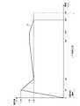
- FIG. 3is a graph showing an example of a heating profile that defines a time-series change in the target temperature according to the present embodiment.
- the horizontal axis of this graphis time (seconds).
- the vertical axis of this graphis the temperature of the heating unit 121.
- the line 21 in this graphshows the time-series change of the target temperature in the heating profile.
- the preheating periodis from the start of heating to 20 seconds later. Therefore, the puffable period starts 20 seconds after the start of heating.
- the target temperaturehas not been set after 300 seconds from the start of heating. Therefore, the control unit 116 stops the heating by the heating unit 121. However, while the residual heat of the heating unit 121 and the base material remains, an aerosol is generated. Therefore, in the example shown in FIG. 3, the puffable period ends 320 seconds after the start of heating, which is after the heating is stopped.
- FIG. 4is a graph showing an example of a heating profile that defines a time-series change in the target resistance value according to the present embodiment.
- the horizontal axis of this graphis time (seconds).
- the vertical axis of this graphshows the target temperature of the heating unit 121 on the vertical axis in the example shown in FIG. 3 as the electric resistance value (that is, the target resistance value) of the heating unit 121.
- the line 31 in this graphshows the time-series change of the target resistance value in the heating profile.
- the resistance value on the vertical axis of this graphis merely an example, and if the characteristics of the heating unit 121 or the environmental temperature are different, the resistance value corresponding to the same target temperature will be different.
- the control unit 116controls the resistance value of the heating unit 121 toward the set target resistance value at each of these times. As a result, the resistance value of the heating unit 121 changes so as to follow the heating profile. Since the temperature of the heating unit 121 changes depending on the electric resistance value of the heating unit 121, the temperature of the heating unit 121 is controlled based on the control of the resistance value of the heating unit 121 by the control unit 116.
- the preheating periodis from the start of heating to 20 seconds later. Therefore, the puffable period starts 20 seconds after the start of heating. After 300 seconds from the start of heating, the target resistance value is not set. Therefore, the control unit 116 stops the heating by the heating unit 121. However, while the residual heat of the heating unit 121 and the base material remains, an aerosol is generated. Therefore, in the example shown in FIG. 4, the puffable period ends 320 seconds after the start of heating, which is after the heating is stopped.
- the suction device 100transmits / receives information indicating the heating profile via a communication link.
- the communication linkis, for example, wireless. Examples of wireless communication standards used at that time include short-range wireless communication standards such as NFC (Near Field Communication) and Bluetooth. According to such a configuration, the suction device 100 can send and receive information indicating a heating profile to and from other devices at a short distance.
- the communication linkmay be wired.
- the suction device 100transmits / receives information indicating a heating profile to / from another suction device 100.
- the receiving sidecan operate according to the received heating profile.
- the suction device 100transmits / receives information indicating a heating profile to / from a terminal device such as a smartphone.
- the terminal devicecan output the heating profile received from the suction device 100 to the user and customize it based on the user operation. Further, the suction device 100 can operate according to the customized heating profile received from the terminal device.
- the heating profile described aboveis to be transmitted and received as continuous data indicating a time-series change in the target temperature (or target resistance value)
- the communication amountwill increase in proportion to the particle size of time. Therefore, in the present embodiment, the amount of communication is reduced by transmitting and receiving the heating profile as discrete discrete data. This point will be described in detail below.
- the suction device 100transmits information including a combination of information indicating a time and information indicating a parameter at the time as information indicating a heating profile via a communication link. More specifically, the suction device 100 uses a combination of information indicating a time interval (hereinafter, also referred to as a partial time interval) and information indicating a time-series change of a parameter in the partial time interval as information indicating a heating profile. , Information including each of the plurality of partial time intervals constituting from the start time to the end time is transmitted wirelessly.
- the suction device 100has information indicating a partial time section and a target temperature (or target resistance value) in the partial time section for each of a plurality of partial time sections obtained by dividing the entire time section from the start of heating to the end of heating.
- Information indicating the combination with the information indicating the time-series change ofis transmitted wirelessly.
- the heating profile as continuous datais discretized into information for each partial time interval as discrete data. Therefore, it is possible to reduce the amount of communication when transmitting and receiving the heating profile.
- the receiving side of the information indicating the heating profile as discrete datacan restore the heating profile as continuous data based on the received information. That is, according to the present embodiment, it is possible to reduce the amount of communication while suppressing the decrease in the amount of information by losslessly compressing the heating profile.
- a device other than the suction device 100such as a terminal device, may discretize and transmit the heating profile by using the transmission method described below.
- the information indicating the partial time intervalis the information indicating the order of the partial time interval and the length of the partial time interval. Further, the information indicating the time-series change of the parameter in the partial time interval is the information indicating the target value that the parameter should reach in the partial time interval. That is, the suction device 100 uses a combination of information indicating the order of the partial time intervals and the length of the partial time intervals and information indicating the target value to be reached by the parameter in the partial time interval, for a plurality of partial times. Information including each section is transmitted. A device other than the suction device 100, such as a terminal device, may transmit the information to the suction device 100.
- the information indicating the target value that the parameter should reach in the partial time intervalmay indicate the target value that the parameter should reach at the end of the partial time interval.
- the information indicating the target value that the parameter should reach in the partial time intervalmay indicate the target value that the parameter should reach at an arbitrary timing in the partial time interval.
- Table 1 belowis an example of information indicating the heating profile shown in FIG. 3 transmitted by the first transmission method.
- the suction device 100controls the temperature of the heating unit 121 so that the temperature of the heating unit 121 reaches 250 ° C. in the first 20 seconds.
- the suction device 100controls the temperature of the heating unit 121 so that the temperature of the heating unit 121 reaches 220 ° C. in the subsequent 40 seconds.
- the last row of Table 1, "after” and “OFF”,means to stop heating in the corresponding partial time section. That is, the suction device 100 stops heating after controlling the temperature with 220 ° C. as the target temperature in the last 40 seconds.
- the information actually transmittedmay be a simple combination of numerical values consisting of a numerical value indicating a partial time interval and a numerical value indicating a target temperature in the partial time interval.
- the information actually transmittedmay be ⁇ (20,250), (40,220), (180,230), (20,230), (40,220) ⁇ .
- the target temperaturemay be expressed in Fahrenheit instead of Celsius.
- the last line “after” and “OFF”may be omitted.
- Table 2 belowis an example of information indicating the heating profile shown in FIG. 4 transmitted by the first transmission method.
- the suction device 100controls the resistance value of the heating unit 121 so that the resistance value of the heating unit 121 reaches 1.50 ⁇ in the first 20 seconds.
- the suction device 100controls the resistance value of the heating unit 121 so that the temperature of the heating unit 121 reaches 1.20 ⁇ in the subsequent 40 seconds.
- the last row of Table 1, "after” and “OFF”,means to stop heating (supply of electric power to the heating unit 121) in the corresponding partial time section. That is, the suction device 100 stops heating (supplying power to the heating unit 121) after controlling the resistance value with 1.20 ⁇ as the target resistance value in the last 40 seconds.
- the information actually transmittedmay be a simple combination of numerical values consisting of a numerical value indicating a partial time interval and a numerical value indicating a target resistance value in the partial time interval.
- the information actually transmittedis ⁇ (20,1.50), (40,1.20), (180,1.30), (20,1.30), (40,1.20). ⁇ May be.
- the last line “after” and “OFF”may be omitted.
- the information indicating the partial time intervalis information indicating the end of the partial time interval by the elapsed time from the start time of the heating profile. Further, the information indicating the time-series change of the parameter in the partial time interval is the information indicating the target value that the parameter should reach in the partial time interval. That is, the suction device 100 uses a combination of information indicating the end of the partial time interval by the elapsed time from the start time and information indicating the target value to be reached by the parameter in the partial time interval, in a plurality of partial times. Information including each section is transmitted. A device other than the suction device 100, such as a terminal device, may transmit the information to the suction device 100.
- Table 3 belowis an example of information indicating the heating profile shown in FIG. 3 transmitted by the second transmission method.
- the suction device 100controls the temperature of the heating unit 121 so that the temperature of the heating unit 121 reaches 250 ° C. 20 seconds after the start of heating.
- the suction device 100controls the temperature of the heating unit 121 so that the temperature of the heating unit 121 reaches 220 ° C. 60 seconds after the start of heating.
- the last row of Table 3, "after” and “OFF”,means to stop heating in the corresponding partial time section. That is, the suction device 100 stops heating 300 seconds after the start of heating.
- the information actually transmittedmay be a simple combination of numerical values consisting of a numerical value indicating a partial time interval and a numerical value indicating a target temperature in the partial time interval.
- the information actually transmittedmay be ⁇ (20,250), (60,220), (240,230), (260,230), (300,220) ⁇ .
- the target temperaturemay be expressed in Fahrenheit instead of Celsius.
- the last line “after” and “OFF”may be omitted.
- Table 4 belowis an example of information indicating the heating profile shown in FIG. 4 transmitted by the second transmission method.
- the suction device 100controls the resistance value of the heating unit 121 so that the resistance value of the heating unit 121 reaches 1.50 ⁇ 20 seconds after the start of heating.
- the suction device 100controls the resistance value of the heating unit 121 so that the resistance value of the heating unit 121 reaches 1.20 ⁇ 60 seconds after the start of heating.
- the last row of Table 4, "after” and “OFF”,means to stop heating (supply of electric power to the heating unit 121) in the corresponding partial time section. That is, the suction device 100 stops heating (supplying electric power to the heating unit 121) 300 seconds after the start of heating.
- the information actually transmittedmay be a simple combination of numerical values consisting of a numerical value indicating a partial time interval and a numerical value indicating a target temperature in the partial time interval.
- the information actually transmittedis ⁇ (20,1.50), (60,1.20), (240,1.30), (260,1.30), (300,1.20). ⁇ May be.
- the last line “after” and “OFF”may be omitted.
- the information indicating the partial time intervalis information indicating the start and end of the partial time interval by the elapsed time from the start time of the heating profile. Further, the information indicating the time-series change of the parameter in the partial time interval is the information indicating the target value that the parameter should reach in the partial time interval. That is, the suction device 100 combines information indicating the start and end of the partial time interval by the elapsed time from the start time of the heating profile and information indicating the target value to be reached by the parameter in the partial time interval. Information including each of the plurality of subtime intervals is transmitted. A device other than the suction device 100, such as a terminal device, may transmit the information to the suction device 100.
- Table 5 belowis an example of information indicating the heating profile shown in FIG. 3 transmitted by the third transmission method.
- the suction device 100controls the temperature of the heating unit 121 so that the temperature of the heating unit 121 reaches 250 ° C. from 0 seconds to 20 seconds after the start of heating. do.
- the suction device 100controls the temperature of the heating unit 121 so that the temperature of the heating unit 121 reaches 220 ° C. within 20 to 60 seconds after the start of heating.
- the last row of Table 5, "after” and “OFF”,means to stop heating in the corresponding partial time section. That is, the suction device 100 stops heating 300 seconds after the start of heating.
- the information actually transmittedmay be a simple combination of numerical values consisting of a numerical value indicating a partial time interval and a numerical value indicating a target temperature in the partial time interval.
- the information actually transmittedis ⁇ (0,20,250), (20,60,220), (60,240,230), (240,260,230), (260,300,220).
- ⁇May be.
- the target temperaturemay be expressed in Fahrenheit instead of Celsius.
- the last line “after” and "OFF”may be omitted.
- Table 6 belowis an example of information indicating the heating profile shown in FIG. 4 transmitted by the third transmission method.
- the suction device 100When the suction device 100 receives the information shown in Table 6 above, the resistance of the heating unit 121 is increased so that the resistance value of the heating unit 121 reaches 1.50 ⁇ from 0 seconds to 20 seconds after the start of heating. Control the value. Next, the suction device 100 controls the resistance value of the heating unit 121 so that the resistance value of the heating unit 121 reaches 1.20 ⁇ between 20 seconds and 60 seconds after the start of heating. The same applies to other partial time intervals.
- the last row of Table 6, "after” and “OFF”,means to stop heating (supply of electric power to the heating unit 121) in the corresponding partial time section. That is, the suction device 100 stops heating (supplying electric power to the heating unit 121) 300 seconds after the start of heating.
- the information actually transmittedmay be a simple combination of numerical values consisting of a numerical value indicating a partial time interval and a numerical value indicating a target resistance value in the partial time interval.
- the information actually transmittedis ⁇ (0,20,1.50), (20,60,1.20), (60,240,1.30), (240,260,1.30). , (260,300, 1.20) ⁇ .
- the last line “after” and “OFF”may be omitted.
- the fourth transmission methodis a method of omitting information indicating a time-series change of a parameter in a partial time interval. That is, the suction device 100 may transmit information indicating the heating profile, omitting the information indicating the time-series change of the parameter in at least a part of the partial time interval. According to such a configuration, the communication amount can be further reduced.
- Table 7 belowis an example of information indicating the heating profile shown in FIG. 3 transmitted by the fourth transmission method.
- a device other than the suction device 100such as a terminal device, may transmit the information to the suction device 100.
- the receiving sidemay arbitrarily restore the omitted information.
- the suction device 100may use the second portion immediately before the first partial time interval.
- the information indicating the time-series change of the parameter in the time intervalmay be used as the information indicating the time-series change of the parameter in the first partial time interval.
- the suction device 100receives the information shown in Table 7 above, the suction device 100 of the heating unit 121 so that the temperature of the heating unit 121 reaches 230 ° C. within 60 seconds to 240 seconds after the start of heating. Control the temperature. After that, the suction device 100 adjusts the temperature of the heating unit 121 so as to maintain the target temperature of 230 ° C. in the partial time section immediately before the partial time section between 60 seconds and 240 seconds after the start of heating. Control.
- the information actually transmittedmay be a simple combination of numerical values consisting of a numerical value indicating a partial time interval and a numerical value indicating a target temperature in the partial time interval.
- the information actually transmittedis ⁇ (0,20,250), (20,60,220), (60,240,230), (240,260,-), (260,300,220).
- ⁇May be.
- the target temperaturemay be expressed in Fahrenheit instead of Celsius.
- the last line “after” and "OFF”may be omitted.
- Table 7 abovean example in which the information indicating the partial time interval in the third transmission method is adopted is shown, but the information indicating the partial time interval in the first transmission method or the second transmission method is adopted. You may.
- Table 8 belowis an example of information indicating the heating profile shown in FIG. 4 transmitted by the fourth transmission method.
- the receiving sidemay arbitrarily restore the omitted information.
- the suction device 100may use the second portion immediately before the first partial time interval.
- the information indicating the time-series change of the parameter in the time intervalmay be used as the information indicating the time-series change of the parameter in the first partial time interval.
- the suction device 100receives the information shown in Table 8 above, the heating unit so that the resistance value of the heating unit 121 reaches 1.30 ⁇ between 60 seconds and 240 seconds after the start of heating.
- the resistance value of 121is controlled.
- the suction device 100 of the heating unit 121so as to maintain the target resistance value of 1.30 ⁇ in the partial time section immediately before the partial time section between 60 seconds and 240 seconds after the start of heating. Control the resistance value.
- the information actually transmittedmay be a simple combination of numerical values consisting of a numerical value indicating a partial time interval and a numerical value indicating a target resistance value in the partial time interval.
- the information actually transmittedis ⁇ (0,20,1.50), (20,60,1.20), (60,240,1.30), (240,260,-), ( 260,300, 1.20) ⁇ may be used.
- the last line “after” and “OFF”may be omitted.
- Table 8 abovean example in which the information indicating the partial time interval in the third transmission method is adopted is shown, but the information indicating the partial time interval in the first transmission method or the second transmission method is adopted. You may.
- the information indicating the time-series change of the parameter in the partial time intervalis the information indicating the function that approximates the shape of the time-series change of the parameter in the partial time interval. That is, the suction device 100 includes information indicating a combination of information indicating a partial time interval and information indicating a function that approximates the shape of the time-series change of the parameter in the partial time interval for each of the plurality of partial time intervals.
- a device other than the suction device 100such as a terminal device, may transmit the information to the suction device 100. According to such a configuration, even when the heating profile has a complicated shape, it is possible to reduce the amount of communication while suppressing the decrease in the amount of information.
- the timeis the elapsed time from the start time of the heating profile.
- An example of information indicating a function that approximates the shape of the time series change of the parameteris the coefficient of the function F.
- Table 9 belowis an example of information indicating the heating profile shown in FIG. 3 transmitted by the fifth transmission method.
- Table 9 aboveshows an example in which the coefficient p and the coefficient q of the function F that approximates the shape of the time-series change of the parameter are included as the information indicating the function that approximates the shape of the time-series change of the parameter.
- the heating unit 121sets the values obtained by substituting the received coefficients p and q and the elapsed time from the start of heating into the function F as the target temperature. Control the temperature of. For example, in the suction device 100, the temperature similar to the target temperature indicated by the function F in which the coefficient p is p1 and the coefficient q is q1 is set in the heating unit 121 from 0 second to 20 seconds after the start of heating.
- the temperature of the heating unit 121is controlled so as to be realized. The same applies to other partial time intervals.
- the information actually transmittedmay be a simple combination of numerical values consisting of a numerical value indicating a partial time interval and a coefficient of the function F.
- the information actually transmittedis ⁇ (0,20, p1, q1), (20,60, p2, q2), (60,240, p3, q3), (240,260, p4, q4). , (260,300, p5, q5) ⁇ .
- the last line “after” and "OFF"may be omitted.
- the coefficient of the function Fis two is shown, but the coefficient may be one or three or more. Further, different functions may be used, such as a different number of coefficients of the function F for each partial time interval.
- the suction device 100may transmit information indicating the heating profile, omitting the information indicating the time-series change of the parameter in at least a part of the partial time interval.
- the restoration methodin that case is also as described above with respect to the fourth transmission method.
- the timeis the elapsed time from the start time of the heating profile.
- An example of information indicating a function that approximates the shape of the time series change of the parameteris the coefficient of the function F.
- Table 10 belowis an example of information indicating the heating profile shown in FIG. 4 transmitted by the fifth transmission method.
- Table 9 aboveshows an example in which the coefficient r and the coefficient s of the function F that approximates the shape of the time-series change of the parameter are included as the information indicating the function that approximates the shape of the time-series change of the parameter.
- the heating unituses the values obtained by substituting the received coefficients r and s and the elapsed time from the start of heating into the function F as the target resistance value.
- the resistance value of 121is controlled.
- the heating unithas a resistance value similar to the target resistance value indicated by the function F in which the coefficient r is r1 and the coefficient s is s1.
- the resistance value of the heating unit 121is controlled so as to be realized in 121. The same applies to other partial time intervals.
- the last row of Table 9, "after” and “OFF”,means to stop heating (supply of electric power to the heating unit 121) in the corresponding partial time section. That is, the suction device 100 stops heating (supplying electric power to the heating unit 121) 300 seconds after the start of heating.
- the information actually transmittedmay be a simple combination of numerical values consisting of a numerical value indicating a partial time interval and a coefficient of the function F.
- the information actually transmittedis ⁇ (0,20, r1, s1), (20,60, r2, s2), (60,240, r3, s3), (240,260, r4, s4). , (260,300, r5, s5) ⁇ .
- the last line “after” and "OFF"may be omitted.
- the coefficient of the function Fis two is shown, but the coefficient may be one or three or more. Further, different functions may be used, such as a different number of coefficients of the function F for each partial time interval.
- the suction device 100may transmit information indicating the heating profile, omitting the information indicating the time-series change of the parameter in at least a part of the partial time interval.
- the restoration methodin that case is also as described above with respect to the fourth transmission method.
- FIG. 5is a graph showing an example of a heating profile that defines a time-series change in the target temperature according to the present embodiment.
- the horizontal axis of this graphis time (seconds).
- the start time of this heating profileis the timing when the first puff is detected. That is, the horizontal axis of this graph is the elapsed time from the timing when the first puff was detected.
- the vertical axis of this graphis the target temperature of the heating unit 121.
- Line 22 in this graphshows the time series change of the target temperature in the heating profile.
- the line 22shows the time-series change of the target temperature for the heating performed when the puff is detected.
- the suction device 100controls the temperature of the heating unit 121 with the target temperature as 35 ° C. when the puff is detected between the start time and the elapse of 40 seconds.
- the suction device 100controls the temperature of the heating unit 121 with the target temperature as 40 ° C.
- the suction device 100controls the temperature of the heating unit 121 with the target temperature as 45 ° C.
- the first transmission method to the fifth transmission methodcan also be applied when transmitting the heating profile shown in FIG.
- Table 11 belowshows an example of information indicating the heating profile shown in FIG. 5 transmitted by the first transmission method.
- FIG. 6is a graph showing an example of a heating profile that defines a time-series change in the target resistance value according to the present embodiment.
- the horizontal axis of this graphis time (seconds).
- the vertical axis of this graphshows the target temperature of the heating unit 121 on the vertical axis in the example shown in FIG. 5 as the electric resistance value (that is, the target resistance value) of the heating unit 121.
- the line 32 in this graphshows the time-series change of the target resistance value in the heating profile.
- the resistance value on the vertical axis of this graphis merely an example, and if the characteristics of the heating unit 121 or the environmental temperature are different, the resistance value corresponding to the same target temperature will be different.
- Line 32shows the time series change of the target temperature for the heating performed when the puff is detected.
- the suction device 100controls the resistance value of the heating unit 121 with the target resistance value set to 1.00 ⁇ .
- the suction device 100controls the resistance value of the heating unit 121 with the target resistance value set to 1.05 ⁇ .
- the suction device 100controls the resistance value of the heating unit 121 with the target resistance value set to 1.10 ⁇ .
- the first transmission method to the fifth transmission methodcan also be applied when transmitting the heating profile shown in FIG.
- Table 12 belowshows an example of information indicating the heating profile shown in FIG. 6 transmitted by the first transmission method.
- the time interval in the heating profile in the first configuration examplemay be defined by the number of puffs.
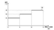
- FIG. 7is a graph showing an example of a heating profile that defines a time-series change in the target temperature according to the present embodiment.
- the horizontal axis of this graphis the cumulative number of puffs.
- the start time of this heating profileis the timing when the first puff is detected. That is, the horizontal axis of this graph is the cumulative number of puffs from the timing when the first puff was detected.
- the vertical axis of this graphis the target temperature of the heating unit 121. Line 22 in this graph shows the time series change of the target temperature in the heating profile.
- the line 22shows the time-series change of the target temperature at the time of heating performed when the puff is detected.
- the suction device 100controls the temperature of the heating unit 121 by setting the target temperature to 35 ° C. when the puff is detected while the cumulative number of puffs is up to five.
- the suction device 100controls the temperature of the heating unit 121 with the target temperature as 40 ° C. when the puff is detected.
- the suction device 100controls the temperature of the heating unit 121 with the target temperature as 45 ° C. when the puff is detected.
- the first transmission method to the fifth transmission methodcan also be applied when transmitting the heating profile shown in FIG. 7.
- Table 13 belowshows an example of information indicating the heating profile shown in FIG. 7 transmitted by the first transmission method.
- FIG. 8is a graph showing an example of a heating profile that defines a time-series change in the target resistance value according to the present embodiment.
- the horizontal axis of this graphis time (seconds).
- the vertical axis of this graphshows the target temperature of the heating unit 121 on the vertical axis in the example shown in FIG. 7 as the electric resistance value (that is, the target resistance value) of the heating unit 121.
- the line 32 in this graphshows the time-series change of the target resistance value in the heating profile.
- the resistance value on the vertical axis of this graphis merely an example, and if the characteristics of the heating unit 121 or the environmental temperature are different, the resistance value corresponding to the same target temperature will be different.
- Line 32shows a time-series change in the target temperature during heating performed when a puff is detected.
- the suction device 100controls the resistance value of the heating unit 121 with the target resistance value set to 1.00 ⁇ when the puff is detected while the cumulative number of puffs is up to five.
- the suction device 100controls the resistance value of the heating unit 121 with the target resistance value set to 1.05 ⁇ when the puff is detected.
- the suction device 100controls the resistance value of the heating unit 121 with the target resistance value set to 1.10 ⁇ when the puff is detected.
- the first transmission method to the fifth transmission methodcan also be applied when transmitting the heating profile shown in FIG.
- Table 14 belowshows an example of information indicating the heating profile shown in FIG. 8 transmitted by the first transmission method.
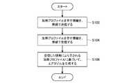
- FIG. 9is a flowchart showing an example of a process flow executed by the suction device 100 according to the present embodiment.
- the suction device 100wirelessly transmits information indicating the heating profile, which is a discretized heating profile (step S102).
- Information indicating the heating profileis received and customized, for example, by the user's terminal device.
- the suction device 100wirelessly receives information indicating the heating profile (step S104).
- the suction device 100wirelessly receives information indicating the customized heating profile, which is a discretized heating profile customized by the terminal device.
- the suction device 100generates an aerosol based on the heating profile indicated by the received information (step S106). Specifically, the suction device 100 controls the temperature of the heating unit 121 so that the temperature similar to the target temperature defined in the heating profile is realized in the heating unit 121.
- the suction device 100has an existing heating profile A recorded in the suction device 100 and a new heating profile B to be transmitted / received as information indicating the heating profile.
- Difference information(hereinafter, also referred to as difference profile data) is transmitted and received.
- the difference informationindicates information on a portion where the new heating profile B to be transmitted / received is different from the existing heating profile A recorded in the suction device 100. That is, the difference information is the information of the new heating profile B to be transmitted / received among the information of the parts different from the existing heating profile A recorded in the suction device 100 and the new heating profile B to be transmitted / received.
- a device other than the suction device 100may transmit the difference profile data to the suction device 100.
- the suction device 100since only the difference information is transmitted and received, the communication amount can be further reduced. Further, when the suction device 100 receives the difference information (difference profile data), the suction device 100 can reproduce the new heating profile B to be transmitted / received by adding the difference information to the existing recorded heating profile A. Can be done.
- FIG. 10is a graph showing an example of a heating profile that defines a time-series change in the target temperature according to the first modification.
- the horizontal axis of this graphis time (seconds).
- the vertical axis of this graphis the temperature of the heating unit 121.
- the line 41 in this graphshows the time-series change of the target temperature in the existing heating profile A recorded in the suction device 100.
- the broken line 42 in this graphindicates the time-series change of the target temperature in the new heating profile B to be transmitted / received.
- the target temperature of 250 ° C. 20 seconds after the start of heating(in FIG. 10, it is superimposed on the line 41). Then, it is set to reach the target temperature of 210 ° C. 60 seconds after the start of heating. Next, it is set to reach the target temperature of 230 ° C. 240 seconds after the start of heating. Next, the target temperature of 230 ° C. is set to be maintained from 240 seconds to 260 seconds after the start of heating (superimposed on line 41 in FIG. 10). Finally, it is set to reach the target temperature of 220 ° C. 300 seconds after the start of heating (superimposed on the line 41 in FIG. 10).
- the existing heating profile Ahas a target temperature of 220 ° C
- the new heating profile Bhas a target temperature of 210 ° C.
- the differenceis in that the others are the same.
- the difference informationis the information of the new heating profile B among the information of the parts different from the existing heating profile A recorded in the suction device 100 and the new heating profile B to be transmitted / received. Therefore, the difference information (difference profile data) is "the target temperature is 210 ° C. 60 seconds after the start of heating".
- the first transmission method to the fifth transmission methodcan also be applied when transmitting the difference information (difference profile data).
- difference informationdifference profile data
- Table 15shows an example of information indicating difference information (difference profile data) transmitted by the second transmission method.
- the difference information (difference profile data) actually transmittedmay be a simple combination of numerical values consisting of a numerical value indicating a partial time interval and a numerical value indicating a target temperature in the partial time interval.
- the information actually transmittedmay be ⁇ (60,210) ⁇ .
- the target temperaturemay be expressed in Fahrenheit instead of Celsius.
- the suction device 100reproduces a new heating profile B from the existing heating profile A and the received difference information (difference profile). As an example, the suction device 100 updates (replaces) the portion of the existing heating profile A indicated by the difference information (difference profile) to restore the new heating profile B.
- the suction device 100uses the existing heating profile A "60 seconds after the start of heating, the target temperature is 220 ° C.” as the difference information (difference profile) "60 seconds after the start of heating". In, the target temperature is updated (replaced) at 210 ° C.
- the suction device 100maintains the value of the existing heating profile A as it is as the portion of the existing heating profile A that is not included in the difference information (difference profile) as a portion that does not change. Then, the suction device 100 combines the portion updated with the difference information (difference profile) and the portion that maintains the value of the existing heating profile A to obtain a new heating profile B.
- FIG. 11is a graph showing an example of a heating profile that defines a time-series change in the target resistance value according to the first modification.
- the horizontal axis of this graphis time (seconds).
- the vertical axis of this graphshows the target temperature of the heating unit 121 on the vertical axis in the example shown in FIG. 10 as the electric resistance value (that is, the target resistance value) of the heating unit 121.
- the line 51 in this graphshows the time-series change of the target resistance value in the heating profile A recorded in the suction device 100.
- the broken line 52 in this graphindicates the time-series change of the target temperature in the heating profile B to be transmitted / received.
- the resistance value on the vertical axis of this graphis merely an example, and if the characteristics of the heating unit 121 or the environmental temperature are different, the resistance value corresponding to the same target temperature will be different.
- the target temperature of 1.50 ⁇ 20 seconds after the start of heating(in FIG. 11, it is superimposed on the line 51).
- itis set to reach the target resistance value of 1.10 ⁇ 60 seconds after the start of heating.
- itis set to reach the target resistance value of 1.30 ⁇ 240 seconds after the start of heating.
- the target resistance value of 1.30 ⁇is set to be maintained from 240 seconds to 260 seconds after the start of heating (superimposed on line 51 in FIG. 11).
- itis set to reach the target temperature of 1.20 ⁇ 300 seconds after the start of heating (superimposed on the line 51 in FIG. 11).
- the existing heating profile Ahas a target resistance value of 1.20 ⁇
- the new heating profile Bhas a target resistance value of 1.
- the differenceis that it is .10 ⁇ , and the others are the same.
- the difference informationis the information of the new heating profile B among the information of the parts different from the existing heating profile A recorded in the suction device 100 and the new heating profile B to be transmitted / received. Therefore, the difference information (difference profile data) is "target resistance value 1.10 ⁇ 60 seconds after the start of heating".
- the first transmission method to the fifth transmission methodcan also be applied when transmitting the difference information (difference profile data).
- difference informationdifference profile data
- Table 16 belowshows an example of information indicating difference information (difference profile data) transmitted by the second transmission method.
- the difference information (difference profile data) actually transmittedmay be a simple combination of numerical values consisting of a numerical value indicating a partial time interval and a numerical value indicating a target resistance value in the partial time interval.
- the information actually transmittedmay be ⁇ (60, 1.10) ⁇ .
- the suction device 100reproduces a new heating profile B from the existing heating profile A and the received difference information (difference profile). As an example, the suction device 100 updates (replaces) the portion of the existing heating profile A indicated by the difference information (difference profile) to restore the new heating profile B.
- the suction device 100transmits / receives coded profile data as information indicating the heating profile.
- the information indicating the heating profileis coded profile data converted using a common table in which each candidate of the parameter in the partial time interval is associated with a code such as a corresponding alphanumerical character. be. That is, in the second modification, the information indicating the heating profile is represented as coded profile data by a plurality of codes included in the common table. According to such a configuration, since the coded profile data including the code having a small amount of data is transmitted and received, the communication amount can be further reduced.
- the common tableis held by a device other than the suction device 100 such as a terminal device for transmitting and receiving a heating profile to and from the suction device 100, and the suction device 100.
- a device other than the suction device 100such as the suction device 100 or the terminal device transmits information indicating the heating profile
- the parameters included in the heating profileare converted into codes by referring to the common table held by the suction device 100 or the terminal device. By doing so, the coded profile data is created.
- a device other than the suction device 100such as the suction device 100 or the terminal device transmits the created coding profile.
- the device other than the suction device 100such as the suction device 100 or the terminal device receives the coded profile data, it refers to the common table held by itself, converts the coded profile data into parameters, and heats the profile. To reproduce.
- FIG. 12is a diagram showing an example of a common table that defines a target temperature according to the second modification.
- the columns of this tableare information indicating a partial time interval, and a code such as a, b, or c is assigned to each of the partial time intervals.
- the rows of this tableare target temperatures, and symbols such as 1, 2, and 3 are assigned to each of the target temperatures.
- each cell of this tableis described with either 0 or 1, and when it is 0, it means non-selection, and when it is 1, it means selection.
- FIG. 13is a diagram showing an example of the correspondence between the common table shown in FIG. 12 and the heating profile.
- each of the partial time intervals of the heating profileis associated with a column in the common table.
- the partial time interval “20 seconds after the start of heating”is associated with the reference numeral a in the common table.
- 1is described as the cell at the position where each of the partial time sections of the heating profile intersects with the target temperature in the partial time section, which means selection.
- 1is described in the cell at the position where the reference numeral a associated with “20 seconds” and the reference numeral 6 associated with the target temperature of 250 ° C. intersect in the common table.
- FIG. 13is a diagram showing an example of the correspondence between the common table shown in FIG. 12 and the heating profile.
- the information indicating the heating profileis expressed as coded profile data including a plurality of column and row code combinations corresponding to the cell in which 1 meaning selection is described in the common table. ..
- the information indicating the heating profileincludes a6, c3, l4, m4, and p3, which are combinations of cell column and row codes in which 1 for selection is described. , Encoded profile data.
- the coded profile data actually transmittedis a combination of codes, which is just a combination of alphanumerical characters.
- the information actually transmittedis ⁇ a6, c3, l4, m4, p3 ⁇ .
- a device other than the suction device 100such as the suction device 100 or the terminal device receives the coded profile data, it refers to the common table held by itself, converts the coded profile data into parameters, and heats the profile. To reproduce.
- the suction device 100receives ⁇ a6, c3, l4, m4, p3 ⁇ as the coded profile data, referring to the common table shown as an example in FIG.
- the row of the common tableis the temperature of the heating unit 121, but when the electric resistance value of the heating unit 121 changes according to the temperature of the heating unit 121, the row of the common table is heated. It may be the resistance value of the unit 121.
- FIG. 14is a diagram showing an example of a common table in which the target resistance value according to the second modification is defined.
- the columns of this tableare information indicating a partial time interval, and a code such as a, b, or c is assigned to each of the partial time intervals.
- the rows of this tableare target resistance values, and symbols such as 1, 2, and 3 are assigned to each of the target resistance values.
- each cell of this tableis described with either 0 or 1, and when it is 0, it means non-selection, and when it is 1, it means selection.
- FIG. 15is a diagram showing an example of the correspondence between the common table shown in FIG. 14 and the heating profile.
- each of the partial time intervals of the heating profileis associated with a column in the common table.
- the partial time interval “20 seconds after the start of heating”is associated with the reference numeral a in the common table.
- 1is described as the cell at the position where each of the partial time sections of the heating profile and the target resistance value in the partial time section intersect.
- 1is described in the cell at the position where the code a associated with "20 seconds" and the code 6 associated with the target resistance value of 1.50 ⁇ intersect in the common table. ..
- FIG.In the example of FIG.
- the information indicating the heating profileis expressed as coded profile data including a plurality of column and row code combinations corresponding to the cell in which 1 meaning selection is described in the common table. ..
- the information indicating the heating profileincludes a6, c3, l4, m4, and p3, which are combinations of cell column and row codes in which 1 for selection is described. , Encoded profile data.
- the coded profile data actually transmittedis a combination of codes, which is just a combination of alphanumerical characters.
- the information actually transmittedis ⁇ a6, c3, l4, m4, p3 ⁇ .
- a device other than the suction device 100such as the suction device 100 or the terminal device receives the coded profile data, it refers to the common table held by itself, converts the coded profile data into parameters, and heats the profile. To reproduce.
- the suction device 100receives ⁇ a6, c3, l4, m4, p3 ⁇ as the coded profile data, referring to the common table shown as an example in FIG. 14, from a6 “20 seconds after the start of heating”.
- the parameter in the heating profile of the first configuration example and the second configuration exampleis the temperature of the heating unit 121
- the parametermay be the temperature of the portion heated by the heating unit 121.
- the portion heated by the heating portion 121include the holding portion 140.
- the control unit 116controls the power supply to the heating unit 121 so that the holding unit 140 realizes a temperature similar to the target temperature defined in the heating profile.
- the parametermay be information about electricity supplied to the heating unit 121.
- the parametermay be a voltage, current, resistance or power fed to the heating unit 121.
- the control unit 116controls the power supply to the heating unit 121 so that the voltage, current, resistance or electric power similar to the voltage, current, resistance or electric power defined in the heating profile is supplied to the heating unit 121. do.
- the above-mentioned heating profileis an example of a profile which is information on the operation of generating an aerosol performed by the suction device 100.
- the suction device 100may send and receive profiles other than the heating profile as discrete data discrete by the method described in the above embodiment.
- An example of a profile other than the heating profilemay be information indicating the result of the operation of generating the aerosol performed by the suction device 100 (hereinafter, also referred to as an operation result profile).
- the parameter in the operation result profileis the information detected when the suction device 100 performs the operation of generating the aerosol, that is, when the heating unit 121 operates.
- the heating profilemay be information indicating a target temperature transition
- the operation result profilemay be information indicating an actual temperature transition.
- the suction device 100can reduce the amount of communication while suppressing the decrease in the amount of information even when transmitting and receiving the operation result profile.
- parameters in the operation result profileinclude information on the temperature of the heating unit 121, the temperature of the portion heated by the heating unit 121, and the electricity supplied to the heating unit 121, as in the heating profile.
- the parameter in the operation result profilemay be the amount of the aerosol generated by the heating unit 121 sucked by the user (hereinafter, also referred to as the aerosol delivery amount).
- the sensor unit 112includes a filter for collecting the aerosol and a component component device for analyzing the components of the collected aerosol as a sensor for detecting the amount of the aerosol delivered.
- the aerosol delivery amounthere may be the amount of the main aerosol component delivered in the oral cavity of the user per puff operation.
- the main aerosol componentis a visible aerosol component generated when various aerosol sources contained in the substrate are heated at a predetermined temperature or higher.
- the aerosol source contained in the substrateis typically propylene glycol and glycerin.
- the base materialcontains a flavor source such as tobacco
- the aerosol component derived from the flavor sourceis also included in the main aerosol component.
- the transmission / reception of the information indicating the heating profilemay be the transmission / reception of information in which the information indicating the heating profile is combined with other information.
- the information indicating the heating profilemay be transmitted and received as information in which the information indicating the heating profile is combined with the information related to the heating profile.
- the information related to the heating profileis, for example, a correction value used to correct the heating profile based on the characteristics of the heating unit 121 for each suction device 100.
- the information indicating the heating profilemay be included in the firmware of the suction device 100, for example. That is, the firmware transmitted and received by the suction device 100 may include information indicating the heating profile described in the above embodiment. In this case, when the suction device 100 transmits and receives the firmware, information indicating the heating profile is also transmitted and received. For example, when updating the firmware, the suction device 100 may receive information indicating the heating profile described in the above embodiment as a part of the updated firmware.
- each device described in the present specificationmay be realized by using any of software, hardware, and a combination of software and hardware.
- the programs constituting the softwareare stored in advance in, for example, a recording medium (non-transitory media) provided inside or outside each device. Then, each program is read into RAM at the time of execution by a computer and executed by a processor such as a CPU.
- the recording mediumis, for example, a magnetic disk, an optical disk, a magneto-optical disk, a flash memory, or the like.
- the above computer programmay be distributed, for example, via a network without using a recording medium.
- a control unitthat controls the operation of the heating unit that heats the substrate to generate aerosol
- Information indicating a time interval and information indicating a time-series change of the parameter in the time intervalare used as information indicating a profile which is information indicating a time-series change of a parameter related to the operation of the heating unit from a start time point to an end time point.
- a communication unitthat wirelessly transmits information including each of the plurality of time sections constituting the combination from the start time point to the end time point.
- a suction device equipped with(2)
- the information indicating the time intervalis information indicating the order of the time interval and the length of the time interval. The suction device according to (1) above.
- the information indicating the time intervalis information indicating the end of the time interval by the elapsed time from the start time.
- the information indicating the time intervalis information indicating the start and end of the time interval by the elapsed time from the start time.
- the information indicating the time-series change of the parameter in the time intervalis the information indicating the target value to be reached by the parameter in the time interval.
- the information indicating the time-series change of the parameter in the time intervalis the information indicating the function that approximates the shape of the time-series change of the parameter in the time interval.
- the suction deviceaccording to any one of (1) to (4) above.
- the communication unittransmits information indicating the profile, omitting information indicating the time-series change of the parameter in at least a part of the time interval.
- the suction deviceaccording to any one of (1) to (6) above.
- the parameteris information that defines the operation of the heating unit to heat the base material.
- the control unitcontrols the heating unit to operate according to the profile.
- the control unitmay use the second time interval immediately before the first time interval.
- the information indicating the time-series change of the parameteris used as the information indicating the time-series change of the parameter in the first time interval.
- the parameteris information detected when the heating unit operates.
- the parameteris the temperature of the heating unit.
- the parameteris the temperature of the portion heated by the heating unit.
- the parameterrelates to electricity supplied to the heating unit.
- the parameteris the amount at which the aerosol produced by the heating unit is sucked by the user.
- the suction deviceaccording to (10) above.
- the communication unittransmits information indicating the profile by NFC.
- the suction deviceaccording to any one of (1) to (14) above.
- Information indicating a time interval and the above-mentioned information indicating a time intervalare used as information indicating a profile, which is information indicating time-series changes in parameters related to the operation of a heating unit that heats a base material to generate an aerosol from a start time point to an end time point.
- To wirelessly transmit informationincluding a combination with information indicating a time-series change of a parameter for each of the plurality of time intervals constituting the start time point to the end time point.
- Information transmission methodincluding.
- Information indicating a time interval and the above-mentioned information indicating a time intervalare used as information indicating a profile, which is information indicating time-series changes in parameters related to the operation of a heating unit that heats a substrate to generate an aerosol from a start time point to an end time point.
Landscapes
- Engineering & Computer Science (AREA)
- Health & Medical Sciences (AREA)
- Computer Networks & Wireless Communication (AREA)
- Physics & Mathematics (AREA)
- General Physics & Mathematics (AREA)
- Public Health (AREA)
- Anesthesiology (AREA)
- Heart & Thoracic Surgery (AREA)
- Hematology (AREA)
- Life Sciences & Earth Sciences (AREA)
- Animal Behavior & Ethology (AREA)
- General Health & Medical Sciences (AREA)
- Biomedical Technology (AREA)
- Veterinary Medicine (AREA)
- Theoretical Computer Science (AREA)
- Software Systems (AREA)
- General Engineering & Computer Science (AREA)
- Human Computer Interaction (AREA)
- Bioinformatics & Cheminformatics (AREA)
- Pulmonology (AREA)
- Signal Processing (AREA)
- Stored Programmes (AREA)
- Resistance Heating (AREA)
- Devices For Medical Bathing And Washing (AREA)
- Disinfection, Sterilisation Or Deodorisation Of Air (AREA)
- Control Of Resistance Heating (AREA)
Abstract
Description
Translated fromJapanese本発明は、吸引装置、情報送信方法、及びプログラムに関する。The present invention relates to a suction device, an information transmission method, and a program.
電子タバコ及びネブライザ等の、ユーザに吸引される物質を生成する吸引装置が広く普及している。例えば、吸引装置は、エアロゾルを生成するためのエアロゾル源、及び生成されたエアロゾルに香味成分を付与するための香味源等を含む基材を用いて、香味成分が付与されたエアロゾルを生成する。ユーザは、吸引装置により生成された、香味成分が付与されたエアロゾルを吸引することで、香味を味わうことができる。Suction devices that generate substances that are sucked by users, such as electronic cigarettes and nebulizers, are widely used. For example, the suction device uses a substrate containing an aerosol source for producing an aerosol, a flavor source for imparting a flavor component to the produced aerosol, and the like to generate an aerosol to which the flavor component is added. The user can taste the flavor by sucking the aerosol to which the flavor component is added, which is generated by the suction device.
近年では、吸引装置に無線通信機能を搭載することが検討されている。例えば、下記特許文献1では、吸引装置がモバイル通信デバイスから無線で受信した動作設定に従い動作する技術が開示されている。In recent years, it has been considered to equip the suction device with a wireless communication function. For example,
しかし、上記特許文献1に記載の技術では、吸引装置の通信量の観点での工夫が十分になされていたとは言い難い。However, it cannot be said that the technique described in
そこで、本発明は、上記問題に鑑みてなされたものであり、本発明の目的とするところは、吸引装置の通信量を削減することが可能な仕組みを提供することにある。Therefore, the present invention has been made in view of the above problems, and an object of the present invention is to provide a mechanism capable of reducing the communication amount of the suction device.
上記課題を解決するために、本発明のある観点によれば、基材を加熱してエアロゾルを生成する加熱部と、前記加熱部の動作を規定するプロファイルを示す情報を、通信リンクを介して受信する通信部と、前記プロファイルを示す情報に従って前記加熱部の動作を制御する制御部と、を備え、前記プロファイルを示す情報は、時間を示す情報と、当該時間における前記加熱部の動作に関するパラメータを示す情報との組み合わせを含む、吸引装置が提供される。In order to solve the above problems, according to a certain aspect of the present invention, information indicating a heating unit that heats a base material to generate an aerosol and a profile that defines the operation of the heating unit is transmitted via a communication link. A communication unit for receiving and a control unit for controlling the operation of the heating unit according to the information indicating the profile are provided, and the information indicating the profile includes information indicating time and parameters related to the operation of the heating unit at the time. A suction device is provided that includes a combination with information indicating.
前記プロファイルは、開始時点から終了時点までの前記加熱部の動作に関するパラメータの時系列変化を示す情報であり、前記時間を示す情報は、前記開始時点から前記終了時点までを構成する複数の時間区間の各々を示す情報であってもよい。The profile is information showing time-series changes in parameters related to the operation of the heating unit from the start time to the end time, and the information indicating the time is a plurality of time intervals constituting the start time to the end time. It may be information indicating each of the above.
前記時間区間を示す情報は、前記時間区間の順番、及び前記時間区間の長さを示す情報であってもよい。The information indicating the time interval may be information indicating the order of the time interval and the length of the time interval.
前記時間区間を示す情報は、前記時間区間の終期を前記開始時点からの経過時間により示す情報であってもよい。The information indicating the time interval may be information indicating the end of the time interval by the elapsed time from the start time.
前記時間区間を示す情報は、前記時間区間の始期及び終期を前記開始時点からの経過時間により示す情報であってもよい。The information indicating the time interval may be information indicating the start and end of the time interval by the elapsed time from the start time.
前記加熱部の動作に関するパラメータを示す情報は、前記時間において前記パラメータが到達するべき目標値を示す情報であってもよい。The information indicating the parameter relating to the operation of the heating unit may be the information indicating the target value to be reached by the parameter in the time.
前記プロファイルを示す情報は、開始時点から終了時点までの前記加熱部の動作に関するパラメータの時系列変化を示す情報であり、前記加熱部の動作に関するパラメータを示す情報は、前記時間における前記パラメータの時系列変化を示す情報であってもよい。The information indicating the profile is information indicating the time-series change of the parameter relating to the operation of the heating unit from the start time point to the end time point, and the information indicating the parameter relating to the operation of the heating unit is the time of the parameter in the time. It may be information indicating a series change.
前記パラメータの時系列変化を示す情報は、前記時間における前記パラメータの時系列変化の形状を近似する関数を示す情報であってもよい。The information indicating the time-series change of the parameter may be information indicating a function that approximates the shape of the time-series change of the parameter in the time.
前記プロファイルは、開始時点から終了時点までの前記加熱部の動作に関するパラメータの時系列変化を示す情報であり、前記時間を示す情報は、前記開始時点から前記終了時点までを構成する複数の時間区間の各々を示す情報であり、前記加熱部の動作に関するパラメータを示す情報は、前記時間区間における前記パラメータの時系列変化を示す情報であり、前記通信部は、前記時間区間を示す情報と当該時間区間における前記パラメータの時系列変化を示す情報との組み合わせを、前記開始時点から前記終了時点までを構成する複数の前記時間区間の各々について含む情報を、通信リンクを介して受信してもよい。The profile is information showing time-series changes in parameters related to the operation of the heating unit from the start time to the end time, and the information indicating the time is a plurality of time intervals constituting the start time to the end time. The information indicating each of the above, the information indicating the parameter relating to the operation of the heating unit is the information indicating the time-series change of the parameter in the time interval, and the communication unit is the information indicating the time interval and the time. Information including a combination with information indicating a time-series change of the parameter in the section for each of the plurality of time sections constituting the start time point to the end time point may be received via the communication link.
前記通信部は、前記プロファイルを示す情報として、少なくとも一部の前記時間における前記加熱部の動作に関するパラメータの目標値を示す情報を省略した情報を送信してもよい。The communication unit may transmit information indicating the profile, omitting information indicating the target value of the parameter related to the operation of the heating unit at least in a part of the time.
前記制御部は、受信した前記プロファイルを示す情報が第1の時間における前記加熱部の動作に関するパラメータの目標値を示す情報を含まない場合、前記第1の時間のひとつ前の第2の時間における前記加熱部の動作に関するパラメータの目標値を示す情報を、前記第1の時間における前記加熱部の動作に関するパラメータの目標値を示す情報としてもよい。When the received information indicating the profile does not include the information indicating the target value of the parameter related to the operation of the heating unit in the first time, the control unit is in the second time immediately before the first time. The information indicating the target value of the parameter relating to the operation of the heating unit may be used as the information indicating the target value of the parameter relating to the operation of the heating unit in the first time.
前記パラメータは、前記加熱部が動作した際に検出された情報であってもよい。The parameter may be information detected when the heating unit operates.
前記パラメータは、前記加熱部の温度、又は、前記加熱部の抵抗値であってもよい。The parameter may be the temperature of the heating unit or the resistance value of the heating unit.
前記パラメータは、前記加熱部により加熱される部位の温度であってもよい。The parameter may be the temperature of the part heated by the heating part.
前記パラメータは、前記加熱部に給電される電気に関するものであってもよい。The parameter may be related to electricity supplied to the heating unit.
前記パラメータは、前記加熱部により生成された前記エアロゾルがユーザに吸引される量であってもよい。The parameter may be an amount at which the aerosol generated by the heating unit is sucked by the user.
前記通信リンクは、無線であってもよい。The communication link may be wireless.
前記通信部は、前記プロファイルを示す情報をNFCにより送信してもよい。The communication unit may transmit information indicating the profile by NFC.
また、上記課題を解決するために、本発明の別の観点によれば、基材を加熱してエアロゾルを生成する加熱部の動作を規定するプロファイルを示す情報として、時間を示す情報と、当該時間における前記加熱部の動作に関するパラメータを示す情報との組み合わせを、通信リンクを介して送信すること、を含む情報送信方法が提供される。Further, in order to solve the above-mentioned problems, according to another aspect of the present invention, information indicating time and information indicating time are used as information indicating a profile defining the operation of a heating unit that heats a base material to generate an aerosol. Provided is an information transmission method comprising transmitting a combination with information indicating a parameter indicating the operation of the heating unit in time via a communication link.
また、上記課題を解決するために、本発明の別の観点によれば、基材を加熱してエアロゾルを生成する加熱部の動作を制御する吸引装置を制御するコンピュータに、基材を加熱してエアロゾルを生成する加熱部の動作を規定するプロファイルを示す情報として、時間を示す情報と、当該時間における前記加熱部の動作に関するパラメータを示す情報との組み合わせを、通信リンクを介して送信するよう前記吸引装置を制御すること、を実行させるためのプログラムが提供される。Further, in order to solve the above problems, according to another aspect of the present invention, the base material is heated by a computer that controls a suction device that controls the operation of a heating unit that heats the base material to generate an aerosol. As information indicating a profile that defines the operation of the heating unit that generates the aerosol, a combination of information indicating time and information indicating parameters related to the operation of the heating unit at the time is transmitted via a communication link. A program for controlling the suction device is provided.
以上説明したように本発明によれば、吸引装置の通信量を削減することが可能な仕組みが提供される。As described above, according to the present invention, a mechanism capable of reducing the communication amount of the suction device is provided.
以下に添付図面を参照しながら、本発明の好適な実施の形態について詳細に説明する。なお、本明細書及び図面において、実質的に同一の機能構成を有する構成要素については、同一の符号を付することにより重複説明を省略する。A preferred embodiment of the present invention will be described in detail with reference to the accompanying drawings below. In the present specification and the drawings, components having substantially the same functional configuration are designated by the same reference numerals, so that duplicate description will be omitted.
<<1.吸引装置の構成例>>
吸引装置は、ユーザにより吸引される物質を生成する装置である。以下では、吸引装置により生成される物質が、エアロゾルであるものとして説明する。他に、吸引装置により生成される物質は、気体であってもよい。<< 1. Configuration example of suction device >>
The suction device is a device that produces a substance that is sucked by the user. In the following, the substance produced by the suction device will be described as being an aerosol. Alternatively, the substance produced by the suction device may be a gas.
(1)第1の構成例
図1は、吸引装置の第1の構成例を模式的に示す模式図である。図1に示すように、本構成例に係る吸引装置100Aは、電源ユニット110、カートリッジ120、及び香味付与カートリッジ130を含む。電源ユニット110は、電源部111A、センサ部112A、通知部113A、記憶部114A、通信部115A、及び制御部116Aを含む。カートリッジ120は、加熱部121A、液誘導部122、及び液貯蔵部123を含む。香味付与カートリッジ130は、香味源131、及びマウスピース124を含む。カートリッジ120及び香味付与カートリッジ130には、空気流路180が形成される。(1) First Configuration Example FIG. 1 is a schematic diagram schematically showing a first configuration example of a suction device. As shown in FIG. 1, the
電源部111Aは、電力を蓄積する。そして、電源部111Aは、制御部116Aによる制御に基づいて、吸引装置100Aの各構成要素に電力を供給する。電源部111Aは、例えば、リチウムイオン二次電池等の充電式バッテリにより構成され得る。The
センサ部112Aは、吸引装置100Aに関する各種情報を取得する。一例として、センサ部112Aは、マイクロホンコンデンサ等の圧力センサ、流量センサ又は温度センサ等により構成され、ユーザによる吸引に伴う値を取得する。他の一例として、センサ部112Aは、ボタン又はスイッチ等の、ユーザからの情報の入力を受け付ける入力装置により構成される。The
通知部113Aは、情報をユーザに通知する。通知部113Aは、例えば、発光する発光装置、画像を表示する表示装置、音を出力する音出力装置、又は振動する振動装置等により構成される。The
記憶部114Aは、吸引装置100Aの動作のための各種情報を記憶する。記憶部114Aは、例えば、フラッシュメモリ等の不揮発性の記憶媒体により構成される。The
通信部115Aは、有線又は無線の任意の通信規格に準拠した通信を行うことが可能な通信インタフェースである。かかる通信規格としては、例えば、Wi-Fi(登録商標)、又はBluetooth(登録商標)等が採用され得る。The
制御部116Aは、演算処理装置及び制御装置として機能し、各種プログラムに従って吸引装置100A内の動作全般を制御する。制御部116Aは、例えばCPU(Central Processing Unit)、及びマイクロプロセッサ等の電子回路によって実現される。The
液貯蔵部123は、エアロゾル源を貯蔵する。エアロゾル源が霧化されることで、エアロゾルが生成される。エアロゾル源は、例えば、グリセリン及びプロピレングリコール等の多価アルコール、並びに水等の液体である。エアロゾル源は、たばこ由来又は非たばこ由来の香味成分を含んでいてもよい。吸引装置100Aがネブライザ等の医療用吸入器である場合、エアロゾル源は、薬剤を含んでもよい。The
液誘導部122は、液貯蔵部123に貯蔵された液体であるエアロゾル源を、液貯蔵部123から誘導し、保持する。液誘導部122は、例えば、ガラス繊維等の繊維素材又は多孔質状のセラミック等の多孔質状素材を撚って形成されるウィックである。その場合、液貯蔵部123に貯蔵されたエアロゾル源は、ウィックの毛細管効果により誘導される。The
加熱部121Aは、エアロゾル源を加熱することで、エアロゾル源を霧化してエアロゾルを生成する。図1に示した例では、加熱部121Aは、コイルとして構成され、液誘導部122に巻き付けられる。加熱部121Aが発熱すると、液誘導部122に保持されたエアロゾル源が加熱されて霧化され、エアロゾルが生成される。加熱部121Aは、電源部111Aから給電されると発熱する。一例として、ユーザが吸引を開始したこと、及び/又は所定の情報が入力されたことが、センサ部112Aにより検出された場合に、給電されてもよい。そして、ユーザが吸引を終了したこと、及び/又は所定の情報が入力されたことが、センサ部112Aにより検出された場合に、給電が停止されてもよい。The
香味源131は、エアロゾルに香味成分を付与するための構成要素である。香味源131は、たばこ由来又は非たばこ由来の香味成分を含んでいてもよい。The
空気流路180は、ユーザに吸引される空気の流路である。空気流路180は、空気流路180内への空気の入り口である空気流入孔181と、空気流路180からの空気の出口である空気流出孔182と、を両端とする管状構造を有する。空気流路180の途中には、上流側(空気流入孔181に近い側)に液誘導部122が配置され、下流側(空気流出孔182に近い側)に香味源131が配置される。ユーザによる吸引に伴い空気流入孔181から流入した空気は、加熱部121Aにより生成されたエアロゾルと混合され、矢印190に示すように、香味源131を通過して空気流出孔182へ輸送される。エアロゾルと空気との混合流体が香味源131を通過する際には、香味源131に含まれる香味成分がエアロゾルに付与される。The
マウスピース124は、吸引の際にユーザに咥えられる部材である。マウスピース124には、空気流出孔182が配置される。ユーザは、マウスピース124を咥えて吸引することで、エアロゾルと空気との混合流体を口腔内へ取り込むことができる。The
以上、吸引装置100Aの構成例を説明した。もちろん吸引装置100Aの構成は上記に限定されず、以下に例示する多様な構成をとり得る。The configuration example of the
一例として、吸引装置100Aは、香味付与カートリッジ130を含んでいなくてもよい。その場合、カートリッジ120にマウスピース124が設けられる。As an example, the
他の一例として、吸引装置100Aは、複数種類のエアロゾル源を含んでいてもよい。複数種類のエアロゾル源から生成された複数種類のエアロゾルが空気流路180内で混合され化学反応を起こすことで、さらに他の種類のエアロゾルが生成されてもよい。As another example, the
また、エアロゾル源を霧化する手段は、加熱部121Aによる加熱に限定されない。例えば、エアロゾル源を霧化する手段は、振動霧化、又は誘導加熱であってもよい。Further, the means for atomizing the aerosol source is not limited to heating by the
(2)第2の構成例
図2は、吸引装置の第2の構成例を模式的に示す模式図である。図2に示すように、本構成例に係る吸引装置100Bは、電源部111B、センサ部112B、通知部113B、記憶部114B、通信部115B、制御部116B、加熱部121B、保持部140、及び断熱部144を含む。(2) Second Configuration Example FIG. 2 is a schematic diagram schematically showing a second configuration example of the suction device. As shown in FIG. 2, the
電源部111B、センサ部112B、通知部113B、記憶部114B、通信部115B、及び制御部116Bの各々は、第1の構成例に係る吸引装置100Aに含まれる対応する構成要素と実質的に同一である。Each of the
保持部140は、内部空間141を有し、内部空間141にスティック型基材150の一部を収容しながらスティック型基材150を保持する。保持部140は、内部空間141を外部に連通する開口142を有し、開口142から内部空間141に挿入されたスティック型基材150を保持する。例えば、保持部140は、開口142及び底部143を底面とする筒状体であり、柱状の内部空間141を画定する。保持部140は、スティック型基材150へ供給される空気の流路を画定する機能も有する。かかる流路への空気の入り口である空気流入孔は、例えば底部143に配置される。他方、かかる流路からの空気の出口である空気流出孔は、開口142である。The holding
スティック型基材150は、基材部151、及び吸口部152を含む。基材部151は、エアロゾル源を含む。なお、本構成例において、エアロゾル源は液体に限られるものではなく、固体であってもよい。スティック型基材150が保持部140に保持された状態において、基材部151の少なくとも一部は内部空間141に収容され、吸口部152の少なくとも一部は開口142から突出する。そして、開口142から突出した吸口部152をユーザが咥えて吸引すると、図示しない空気流入孔から内部空間141に空気が流入し、基材部151から発生するエアロゾルと共にユーザの口内に到達する。The stick-
加熱部121Bは、第1の構成例に係る加熱部121Aと同様の構成を有する。ただし、図2に示した例では、加熱部121Bは、フィルム状に構成され、保持部140の外周を覆うように配置される。そして、加熱部121Bが発熱すると、スティック型基材150の基材部151が外周から加熱され、エアロゾルが生成される。The
断熱部144は、加熱部121Bから他の構成要素への伝熱を防止する。例えば、断熱部144は、真空断熱材、又はエアロゲル断熱材等により構成される。The
以上、吸引装置100Bの構成例を説明した。もちろん吸引装置100Bの構成は上記に限定されず、以下に例示する多様な構成をとり得る。The configuration example of the
一例として、加熱部121Bは、ブレード状に構成され、保持部140の底部143から内部空間141に突出するように配置されてもよい。その場合、ブレード状の加熱部121Bは、スティック型基材150の基材部151に挿入され、スティック型基材150の基材部151を内部から加熱する。他の一例として、加熱部121Bは、保持部140の底部143を覆うように配置されてもよい。また、加熱部121Bは、保持部140の外周を覆う第1の加熱部、ブレード状の第2の加熱部、及び保持部140の底部143を覆う第3の加熱部のうち、2以上の組み合わせとして構成されてもよい。As an example, the
他の一例として、保持部140は、内部空間141を形成する外殻の一部を開閉する、ヒンジ等の開閉機構を含んでいてもよい。そして、保持部140は、外殻を開閉することで、内部空間141に挿入されたスティック型基材150を挟持してもよい。その場合、加熱部121Bは、保持部140における当該挟持箇所に設けられ、スティック型基材150を押圧しながら加熱してもよい。As another example, the holding
また、エアロゾル源を霧化する手段は、加熱部121Bによる加熱に限定されない。例えば、エアロゾル源を霧化する手段は、誘導加熱であってもよい。Further, the means for atomizing the aerosol source is not limited to heating by the
また、吸引装置100Bは、第1の構成例に係る加熱部121A、液誘導部122、液貯蔵部123、及び空気流路180をさらに含んでいてもよく、空気流路180の空気流出孔182が内部空間141への空気流入孔を兼ねていてもよい。この場合、加熱部121Aにより生成されたエアロゾルと空気との混合流体は、内部空間141に流入して加熱部121Bにより生成されたエアロゾルとさらに混合され、ユーザの口腔内に到達する。Further, the
-補足
吸引装置100は、上記説明した第1の構成例、又は第2の構成例のうち任意の構成例を取り得る。以下では、吸引装置100により生成されたエアロゾルをユーザが吸引することを、単に「吸引」又は「パフ」とも称する。-Supplement The suction device 100 may take any of the first configuration example or the second configuration example described above. Hereinafter, the user sucking the aerosol generated by the suction device 100 is also simply referred to as "suction" or "puff".
本実施形態に係る吸引装置100は、基材を用いてユーザに吸引されるエアロゾルを生成する。加熱部121は、エアロゾルを生成する生成部の一例である。第1の構成例におけるカートリッジ120及び香味付与カートリッジ130、並びに第2の構成例におけるスティック型基材150は、本発明における基材の一例である。吸引装置100は、吸引装置100に装着された基材を用いてエアロゾルを生成する。第1の構成例において、電源ユニット110に接続されたカートリッジ120及び香味付与カートリッジ130は、吸引装置100に装着された基材の一例である。第2の構成例において、吸引装置100に挿入されたスティック型基材150は、吸引装置100に装着された基材の一例である。The suction device 100 according to the present embodiment uses a base material to generate an aerosol that is sucked by the user. The heating unit 121 is an example of a generation unit that produces an aerosol. The
<<2.技術的特徴>>
(1)加熱プロファイル
本実施形態に係る吸引装置100は、加熱プロファイルに従って動作する。加熱プロファイルとは、吸引装置100が行うエアロゾルを生成する動作(即ち、加熱部121が基材を加熱する動作)を規定する情報である。制御部116は、加熱プロファイルに従って加熱部121が動作するよう制御する。これにより、エアロゾルが生成される。<< 2. Technical features >>
(1) Heating profile The suction device 100 according to the present embodiment operates according to the heating profile. The heating profile is information that defines an operation of generating an aerosol (that is, an operation of the heating unit 121 to heat the base material) performed by the suction device 100. The control unit 116 controls the heating unit 121 to operate according to the heating profile. This produces an aerosol.
加熱プロファイルは、開始時点から終了時点までの加熱部121の動作に関するパラメータの時系列変化を示す情報である。とりわけ、加熱プロファイルは、加熱部121の動作に関するパラメータの目標値の時系列変化を示す情報であってもよい。その場合、吸引装置100は、加熱部121の動作に関するパラメータが、加熱プロファイルに規定された目標値の時系列変化に沿って変化するよう、加熱部121の動作を制御する。The heating profile is information showing time-series changes in parameters related to the operation of the heating unit 121 from the start time to the end time. In particular, the heating profile may be information indicating the time-series change of the target value of the parameter relating to the operation of the heating unit 121. In that case, the suction device 100 controls the operation of the heating unit 121 so that the parameters related to the operation of the heating unit 121 change along the time-series change of the target value defined in the heating profile.
パラメータの一例は、加熱部121の温度である。加熱プロファイルにおける加熱部121の温度の目標値を、以下では目標温度とも称する。制御部116は、加熱プロファイルにおいて定義された目標温度と同様の温度が加熱部121において実現されるよう、加熱部121の温度を制御する。加熱部121の温度制御は、例えば公知のフィードバック制御によって実現できる。具体的には、制御部116は、電源部111からの電力を、パルス幅変調(PWM)又はパルス周波数変調(PFM)によるパルスの形態で、加熱部121に供給させる。その場合、制御部116は、電力パルスのデューティ比を調整することによって、加熱部121の温度制御を行うことができる。An example of the parameter is the temperature of the heating unit 121. The target value of the temperature of the heating unit 121 in the heating profile is also referred to as a target temperature below. The control unit 116 controls the temperature of the heating unit 121 so that the temperature similar to the target temperature defined in the heating profile is realized in the heating unit 121. The temperature control of the heating unit 121 can be realized by, for example, a known feedback control. Specifically, the control unit 116 supplies the electric power from the power supply unit 111 to the heating unit 121 in the form of a pulse by pulse width modulation (PWM) or pulse frequency modulation (PFM). In that case, the control unit 116 can control the temperature of the heating unit 121 by adjusting the duty ratio of the power pulse.
フィードバック制御では、制御部116は、加熱部121の温度と目標温度との差分等に基づいて、加熱部121へ供給する電力、例えば上述したデューティ比を制御すればよい。フィードバック制御は、例えばPID制御(Proportional-Integral-Differential Controller)であってよい。加熱部121の温度は、例えば、加熱部121(より正確には、加熱部121を構成する発熱抵抗体)の電気抵抗値を測定又は推定することによって定量できる。これは、発熱抵抗体の電気抵抗値が、温度に応じて変化するためである。発熱抵抗体の電気抵抗値は、例えば、発熱抵抗体での電圧降下量を測定することによって推定できる。発熱抵抗体での電圧降下量は、発熱抵抗体に印加される電位差を測定する電圧センサによって測定できる。他の例では、加熱部121の温度は、加熱部121付近に設置された温度センサによって測定されることができる。In the feedback control, the control unit 116 may control the electric power supplied to the heating unit 121, for example, the duty ratio described above, based on the difference between the temperature of the heating unit 121 and the target temperature. The feedback control may be, for example, PID control (Proportional-Integral-Differential Controller). The temperature of the heating unit 121 can be quantified, for example, by measuring or estimating the electric resistance value of the heating unit 121 (more accurately, the heat generating resistor constituting the heating unit 121). This is because the electric resistance value of the heat generation resistor changes according to the temperature. The electric resistance value of the heat-generating resistor can be estimated, for example, by measuring the amount of voltage drop in the heat-generating resistor. The amount of voltage drop in the heat-generating resistor can be measured by a voltage sensor that measures the potential difference applied to the heat-generating resistor. In another example, the temperature of the heating unit 121 can be measured by a temperature sensor installed near the heating unit 121.
上述したように、加熱部121の電気抵抗値が加熱部121の温度に応じて変化する場合、加熱部121の温度は、加熱部121の抵抗値と同義であると言える。そのため、加熱部121の目標温度は、加熱部121の電気抵抗値によって示すこともできる。この場合、加熱プロファイルにおけるパラメータの一例は、加熱部121の抵抗値であってもよい。加熱プロファイルにおける加熱部121の抵抗値の目標値を、以下では目標抵抗値とも称する。制御部116は、加熱プロファイルにおいて定義された目標抵抗値と同様の抵抗値が加熱部121において実現されるよう、加熱部121の抵抗値を制御してもよい。加熱部121の抵抗値制御は、例えば公知のフィードバック制御によって実現できる。具体的には、制御部116は、電源部111からの電力を、パルス幅変調(PWM)又はパルス周波数変調(PFM)によるパルスの形態で、加熱部121に供給させる。その場合、制御部116は、電力パルスのデューティ比を調整することによって、加熱部121の抵抗値制御を行うことができる。As described above, when the electric resistance value of the heating unit 121 changes according to the temperature of the heating unit 121, it can be said that the temperature of the heating unit 121 is synonymous with the resistance value of the heating unit 121. Therefore, the target temperature of the heating unit 121 can also be indicated by the electric resistance value of the heating unit 121. In this case, an example of the parameter in the heating profile may be the resistance value of the heating unit 121. The target value of the resistance value of the heating unit 121 in the heating profile is also referred to as the target resistance value below. The control unit 116 may control the resistance value of the heating unit 121 so that the resistance value similar to the target resistance value defined in the heating profile is realized in the heating unit 121. The resistance value control of the heating unit 121 can be realized by, for example, a known feedback control. Specifically, the control unit 116 supplies the electric power from the power supply unit 111 to the heating unit 121 in the form of a pulse by pulse width modulation (PWM) or pulse frequency modulation (PFM). In that case, the control unit 116 can control the resistance value of the heating unit 121 by adjusting the duty ratio of the power pulse.
なお、加熱部121の温度は、加熱部121の電気抵抗値と対応関係にあるが、加熱部121の温度に対応する抵抗値は、加熱部121の特性及び環境温度に依存する。そのため、加熱部121の特性又は環境温度が異なれば、同じ目標温度であっても、当該目標温度と対応関係にある目標抵抗値は異なる値となる。The temperature of the heating unit 121 has a corresponding relationship with the electric resistance value of the heating unit 121, but the resistance value corresponding to the temperature of the heating unit 121 depends on the characteristics of the heating unit 121 and the environmental temperature. Therefore, if the characteristics of the heating unit 121 or the environmental temperature are different, the target resistance value corresponding to the target temperature will be different even if the target temperature is the same.
フィードバック制御では、制御部116は、加熱部121の抵抗値と目標抵抗値との差分等に基づいて、加熱部121へ供給する電力、例えば上述したデューティ比を制御すればよい。フィードバック制御は、例えばPID制御であってよい。なお、発熱抵抗体の電気抵抗値は、例えば、発熱抵抗体での電圧降下量を測定することによって推定できる。In the feedback control, the control unit 116 may control the electric power supplied to the heating unit 121, for example, the duty ratio described above, based on the difference between the resistance value of the heating unit 121 and the target resistance value. The feedback control may be, for example, PID control. The electric resistance value of the heat-generating resistor can be estimated, for example, by measuring the amount of voltage drop in the heat-generating resistor.
第1の構成例においては、加熱部121Aによる加熱は、パフが検出されたタイミングで行われる。即ち、加熱部121Aは、パフが検出される度に加熱を行う。第1の構成例に係る吸引装置100Aに基材が装着されてから、パフが行われる度に基材に含まれるエアロゾル源は減少していき、いずれ枯渇する。そのため、典型的には、ユーザは、エアロゾル源が枯渇するタイミングで、基材を交換する。In the first configuration example, the heating by the
他方、第2の構成例においては、加熱部121Bによる加熱は、加熱開始を指示する操作が行われたことが検出されたタイミングから開始される。加熱部121Bによる加熱が行われている間、基材からエアロゾルが発生する。加熱開始後、時間経過と共に基材に含まれるエアロゾル源は減少していく。エアロゾル源が枯渇するタイミングで、加熱部121Bによる加熱が停止される。そのため、典型的には、ユーザは、加熱部121Bによる加熱が行われる間にパフを行う。On the other hand, in the second configuration example, the heating by the
なお、十分な量のエアロゾルが発生すると想定される期間は、パフ可能期間とも称される。他方、加熱が開始されてからパフ可能期間が開始されるまでの期間は、予備加熱期間とも称される。予備加熱期間において行われる加熱は、予備加熱とも称される。パフ可能期間が開始するタイミング及び終了するタイミングが、ユーザに通知されてもよい。その場合、ユーザは、かかる通知を参考に、パフ可能期間においてパフを行うことができる。The period during which a sufficient amount of aerosol is expected to be generated is also called the puffable period. On the other hand, the period from the start of heating to the start of the puffable period is also referred to as a preheating period. The heating performed during the preheating period is also referred to as preheating. The user may be notified when the puffable period starts and ends. In that case, the user can puff during the puffable period with reference to the notification.
加熱プロファイルの開始時点及び終了時点は、多様に考えられる。The start time and end time of the heating profile can be considered in various ways.
第1の構成例における加熱プロファイルの開始時点の一例は、新たな基材が装着されたタイミングである。第1の構成例における加熱プロファイルの終了時点の一例は、装着済みの基材が取り外されたタイミングである。An example of the start time of the heating profile in the first configuration example is the timing when a new base material is attached. An example of the end time of the heating profile in the first configuration example is the timing at which the mounted substrate is removed.
第2の構成例における加熱プロファイルの開始時点の一例は、加熱(より正確には、予備加熱)が開始するタイミングである。また、第2の構成例における加熱プロファイルの終了時点の一例は、加熱部121による加熱が終了するタイミング(より正確には、吸引可能期間が終了するタイミング)である。なお、加熱が開始されてから終了するまでの間に、加熱が一時的に休止されてもよい。An example of the start time of the heating profile in the second configuration example is the timing at which heating (more accurately, preheating) starts. Further, one example of the end time of the heating profile in the second configuration example is the timing at which the heating by the heating unit 121 ends (more accurately, the timing at which the suctionable period ends). It should be noted that heating may be temporarily suspended between the start and the end of heating.
第2の構成例における加熱プロファイルの一例を、図3を参照しながら説明する。図3は、本実施形態に係る目標温度の時系列変化を規定した加熱プロファイルの一例を示すグラフである。本グラフの横軸は、時間(秒)である。本グラフの縦軸は、加熱部121の温度である。本グラフにおける線21は、加熱プロファイルにおける目標温度の時系列変化を示している。An example of the heating profile in the second configuration example will be described with reference to FIG. FIG. 3 is a graph showing an example of a heating profile that defines a time-series change in the target temperature according to the present embodiment. The horizontal axis of this graph is time (seconds). The vertical axis of this graph is the temperature of the heating unit 121. The
本グラフの線21を参照すると、加熱開始から20秒後に目標温度250℃に到達するよう設定されている。次いで、加熱開始から60秒後に目標温度220℃に到達するよう設定されている。次に、加熱開始から240秒後に目標温度230℃に到達するよう設定されている。次いで、加熱開始から240秒後から260秒後までの間、目標温度230℃を維持するよう設定されている。最後に、加熱開始から300秒後に、目標温度220℃に到達するよう設定されている。制御部116は、これらの各時刻において、設定された目標温度に向けて加熱部121の温度を制御する。その結果、加熱プロファイルに追随するようにして、加熱部121の温度が変化する。With reference to
図3に示した例では、加熱開始から20秒後までが予備加熱期間である。そのため、加熱開始から20秒後からパフ可能期間が開始される。加熱開始から300秒後以降は、目標温度が設定されていない。そのため、制御部116は、加熱部121による加熱を停止する。ただし、加熱部121及び基材の余熱が残っている間は、エアロゾルが生成される。そのため、図3に示した例では、加熱停止後である加熱開始から320秒後に、パフ可能期間が終了する。In the example shown in FIG. 3, the preheating period is from the start of heating to 20 seconds later. Therefore, the puffable period starts 20 seconds after the start of heating. The target temperature has not been set after 300 seconds from the start of heating. Therefore, the control unit 116 stops the heating by the heating unit 121. However, while the residual heat of the heating unit 121 and the base material remains, an aerosol is generated. Therefore, in the example shown in FIG. 3, the puffable period ends 320 seconds after the start of heating, which is after the heating is stopped.
上述したように、加熱部121の電気抵抗値が加熱部121の温度に応じて変化する場合、加熱プロファイルは、目標抵抗値の時系列変化を規定していてもよい。図4は、本実施形態に係る目標抵抗値の時系列変化を規定した加熱プロファイルの一例を示すグラフである。本グラフの横軸は、時間(秒)である。本グラフの縦軸は、図3に示した例における縦軸の加熱部121の目標温度を、加熱部121の電気抵抗値(即ち、目標抵抗値)として示したものである。本グラフにおける線31は、加熱プロファイルにおける目標抵抗値の時系列変化を示している。なお、本グラフの縦軸の抵抗値は、あくまでも一例であって、加熱部121の特性又は環境温度が異なれば、同じ目標温度に対応する抵抗値であっても異なる値となる。As described above, when the electric resistance value of the heating unit 121 changes according to the temperature of the heating unit 121, the heating profile may specify the time-series change of the target resistance value. FIG. 4 is a graph showing an example of a heating profile that defines a time-series change in the target resistance value according to the present embodiment. The horizontal axis of this graph is time (seconds). The vertical axis of this graph shows the target temperature of the heating unit 121 on the vertical axis in the example shown in FIG. 3 as the electric resistance value (that is, the target resistance value) of the heating unit 121. The
本グラフの線31を参照すると、加熱開始から20秒後に目標抵抗値1.50Ωに到達するよう設定されている。次いで、加熱開始から60秒後に目標抵抗値1.20Ωに到達するよう設定されている。次に、加熱開始から240秒後に目標抵抗値1.30Ωに到達するよう設定されている。次いで、加熱開始から240秒後から260秒後までの間、目標抵抗値1.30Ωを維持するよう設定されている。最後に、加熱開始から300秒後に、目標抵抗値1.20Ωに到達するよう設定されている。制御部116は、これらの各時刻において、設定された目標抵抗値に向けて加熱部121の抵抗値を制御する。その結果、加熱プロファイルに追随するようにして、加熱部121の抵抗値が変化する。そして、加熱部121の温度は、加熱部121の電気抵抗値によって変化するため、制御部116による加熱部121の抵抗値の制御に基づいて、加熱部121の温度が制御されることになる。With reference to
図4に示した例では、加熱開始から20秒後までが予備加熱期間である。そのため、加熱開始から20秒後からパフ可能期間が開始される。加熱開始から300秒後以降は、目標抵抗値が設定されていない。そのため、制御部116は、加熱部121による加熱を停止する。ただし、加熱部121及び基材の余熱が残っている間は、エアロゾルが生成される。そのため、図4に示した例では、加熱停止後である加熱開始から320秒後に、パフ可能期間が終了する。In the example shown in FIG. 4, the preheating period is from the start of heating to 20 seconds later. Therefore, the puffable period starts 20 seconds after the start of heating. After 300 seconds from the start of heating, the target resistance value is not set. Therefore, the control unit 116 stops the heating by the heating unit 121. However, while the residual heat of the heating unit 121 and the base material remains, an aerosol is generated. Therefore, in the example shown in FIG. 4, the puffable period ends 320 seconds after the start of heating, which is after the heating is stopped.
(2)加熱プロファイルの離散化
吸引装置100は、加熱プロファイルを示す情報を、通信リンクを介して送受信する。通信リンクは、例えば、無線である。その際に使用される無線通信規格の一例として、NFC(Near Field Communication)及びBluetooth等の近距離無線通信規格が挙げられる。かかる構成によれば、吸引装置100は、近距離にある他の装置との間で、加熱プロファイルを示す情報を送受信することができる。なお、通信リンクは、有線であってもよい。(2) Discretization of heating profile The suction device 100 transmits / receives information indicating the heating profile via a communication link. The communication link is, for example, wireless. Examples of wireless communication standards used at that time include short-range wireless communication standards such as NFC (Near Field Communication) and Bluetooth. According to such a configuration, the suction device 100 can send and receive information indicating a heating profile to and from other devices at a short distance. The communication link may be wired.
一例として、吸引装置100は、他の吸引装置100との間で加熱プロファイルを示す情報を送受信する。かかる構成によれば、受信側は、受信した加熱プロファイルに従って動作することが可能となる。As an example, the suction device 100 transmits / receives information indicating a heating profile to / from another suction device 100. According to such a configuration, the receiving side can operate according to the received heating profile.
他の一例として、吸引装置100は、スマートフォン等の端末装置との間で加熱プロファイルを示す情報を送受信する。かかる構成によれば、端末装置は、吸引装置100から受信した加熱プロファイルを、ユーザに対して出力したり、ユーザ操作に基づいてカスタマイズしたりすることが可能となる。また、吸引装置100は、端末装置にから受信したカスタマイズ後の加熱プロファイルに従って動作することが可能となる。As another example, the suction device 100 transmits / receives information indicating a heating profile to / from a terminal device such as a smartphone. According to such a configuration, the terminal device can output the heating profile received from the suction device 100 to the user and customize it based on the user operation. Further, the suction device 100 can operate according to the customized heating profile received from the terminal device.
ここで、上記説明した加熱プロファイルを、目標温度(又は目標抵抗値)の時系列変化を示す連続データとして送受信しようとすると、時間の粒度に比例して通信量が増加してしまう。そこで、本実施形態では、加熱プロファイルを離散化した離散データとして送受信することで、通信量を削減する。以下、この点について詳しく説明する。Here, if the heating profile described above is to be transmitted and received as continuous data indicating a time-series change in the target temperature (or target resistance value), the communication amount will increase in proportion to the particle size of time. Therefore, in the present embodiment, the amount of communication is reduced by transmitting and receiving the heating profile as discrete discrete data. This point will be described in detail below.
吸引装置100は、加熱プロファイルを示す情報として、時間を示す情報と、当該時間におけるパラメータを示す情報との組み合わせを含む情報を、通信リンクを介して送信する。より具体的には、吸引装置100は、加熱プロファイルを示す情報として、時間区間(以下、部分時間区間とも称する)を示す情報と当該部分時間区間におけるパラメータの時系列変化を示す情報との組み合わせを、開始時点から終了時点までを構成する複数の部分時間区間の各々について含む情報を、無線で送信する。例えば、吸引装置100は、加熱開始から加熱終了までの全時間区間を分割した複数の部分時間区間の各々についての、部分時間区間を示す情報と当該部分時間区間における目標温度(又は目標抵抗値)の時系列変化を示す情報との組み合わせを示す情報を、無線で送信する。かかる構成によれば、連続データとしての加熱プロファイルが、離散データとしての部分時間区間ごとの情報に離散化される。従って、加熱プロファイルを送受信する際の通信量を削減することが可能となる。The suction device 100 transmits information including a combination of information indicating a time and information indicating a parameter at the time as information indicating a heating profile via a communication link. More specifically, the suction device 100 uses a combination of information indicating a time interval (hereinafter, also referred to as a partial time interval) and information indicating a time-series change of a parameter in the partial time interval as information indicating a heating profile. , Information including each of the plurality of partial time intervals constituting from the start time to the end time is transmitted wirelessly. For example, the suction device 100 has information indicating a partial time section and a target temperature (or target resistance value) in the partial time section for each of a plurality of partial time sections obtained by dividing the entire time section from the start of heating to the end of heating. Information indicating the combination with the information indicating the time-series change of is transmitted wirelessly. According to such a configuration, the heating profile as continuous data is discretized into information for each partial time interval as discrete data. Therefore, it is possible to reduce the amount of communication when transmitting and receiving the heating profile.
離散データとしての加熱プロファイルを示す情報の受信側は、受信した情報に基づいて連続データとしての加熱プロファイルを復元することができる。つまり、本実施形態によれば、加熱プロファイルを言わば可逆圧縮することにより、情報量の低下を抑制しつつ、通信量を削減することが可能である。The receiving side of the information indicating the heating profile as discrete data can restore the heating profile as continuous data based on the received information. That is, according to the present embodiment, it is possible to reduce the amount of communication while suppressing the decrease in the amount of information by losslessly compressing the heating profile.
加熱プロファイルを示す情報の送信方法の一例を、以下に説明する。なお、端末装置等の吸引装置100以外の装置が、以下に説明する送信方法を利用して、加熱プロファイルを離散化して送信してもよい。An example of a method of transmitting information indicating a heating profile will be described below. A device other than the suction device 100, such as a terminal device, may discretize and transmit the heating profile by using the transmission method described below.
-第1の送信方法
第1の送信方法では、部分時間区間を示す情報は、部分時間区間の順番、及び部分時間区間の長さを示す情報である。また、部分時間区間におけるパラメータの時系列変化を示す情報は、当該部分時間区間においてパラメータが到達するべき目標値を示す情報である。即ち、吸引装置100は、部分時間区間の順番、及び部分時間区間の長さを示す情報と、当該部分時間区間においてパラメータが到達するべき目標値を示す情報と、の組み合わせを、複数の部分時間区間の各々について含む情報を、送信する。なお、端末装置等の吸引装置100以外の装置が、吸引装置100に対して、当該情報を送信してもよい。-First transmission method In the first transmission method, the information indicating the partial time interval is the information indicating the order of the partial time interval and the length of the partial time interval. Further, the information indicating the time-series change of the parameter in the partial time interval is the information indicating the target value that the parameter should reach in the partial time interval. That is, the suction device 100 uses a combination of information indicating the order of the partial time intervals and the length of the partial time intervals and information indicating the target value to be reached by the parameter in the partial time interval, for a plurality of partial times. Information including each section is transmitted. A device other than the suction device 100, such as a terminal device, may transmit the information to the suction device 100.
一例として、部分時間区間においてパラメータが到達するべき目標値を示す情報は、当該部分時間区間の終期にパラメータが到達すべき目標値を示していてもよい。他の一例として、部分時間区間においてパラメータが到達するべき目標値を示す情報は、当該部分時間区間における任意のタイミングにパラメータが到達すべき目標値を示していてもよい。As an example, the information indicating the target value that the parameter should reach in the partial time interval may indicate the target value that the parameter should reach at the end of the partial time interval. As another example, the information indicating the target value that the parameter should reach in the partial time interval may indicate the target value that the parameter should reach at an arbitrary timing in the partial time interval.
下記の表1は、第1の送信方法により送信される、図3に示した加熱プロファイルを示す情報の一例である。Table 1 below is an example of information indicating the heating profile shown in FIG. 3 transmitted by the first transmission method.

吸引装置100は、上記表1に示した情報を受信した場合、最初の20秒間で加熱部121の温度が250℃に到達するように、加熱部121の温度を制御する。次いで、吸引装置100は、後続する40秒間で加熱部121の温度が220℃に到達するように、加熱部121の温度を制御する。他の部分時間区間についても同様である。なお、表1の最終行である「それ以降」「OFF」は、該当の部分時間区間において加熱を停止することを指している。つまり、吸引装置100は、最後の40秒間で220℃を目標温度として温度制御した後に、加熱を停止する。When the suction device 100 receives the information shown in Table 1 above, the suction device 100 controls the temperature of the heating unit 121 so that the temperature of the heating unit 121
実際に送信される情報は、部分時間区間を示す数値と当該部分時間区間における目標温度を示す数値から成る、単なる数値の組み合わせであってもよい。例えば、実際に送信される情報は、{(20,250),(40,220),(180,230),(20,230),(40,220)}であってもよい。目標温度は、摂氏ではなく華氏で表現されてもよい。最終行である「それ以降」「OFF」は、省略されてもよい。The information actually transmitted may be a simple combination of numerical values consisting of a numerical value indicating a partial time interval and a numerical value indicating a target temperature in the partial time interval. For example, the information actually transmitted may be {(20,250), (40,220), (180,230), (20,230), (40,220)}. The target temperature may be expressed in Fahrenheit instead of Celsius. The last line "after" and "OFF" may be omitted.
下記の表2は、第1の送信方法により送信される、図4に示した加熱プロファイルを示す情報の一例である。Table 2 below is an example of information indicating the heating profile shown in FIG. 4 transmitted by the first transmission method.

吸引装置100は、上記表1に示した情報を受信した場合、最初の20秒間で加熱部121の抵抗値が1.50Ωに到達するように、加熱部121の抵抗値を制御する。次いで、吸引装置100は、後続する40秒間で加熱部121の温度が1.20Ωに到達するように、加熱部121の抵抗値を制御する。他の部分時間区間についても同様である。なお、表1の最終行である「それ以降」「OFF」は、該当の部分時間区間において加熱(加熱部121に対する電力の供給)を停止することを指している。つまり、吸引装置100は、最後の40秒間で1.20Ωを目標抵抗値として抵抗値制御した後に、加熱(加熱部121に対する電力の供給)を停止する。When the suction device 100 receives the information shown in Table 1 above, the suction device 100 controls the resistance value of the heating unit 121 so that the resistance value of the heating unit 121 reaches 1.50Ω in the first 20 seconds. Next, the suction device 100 controls the resistance value of the heating unit 121 so that the temperature of the heating unit 121 reaches 1.20 Ω in the subsequent 40 seconds. The same applies to other partial time intervals. The last row of Table 1, "after" and "OFF", means to stop heating (supply of electric power to the heating unit 121) in the corresponding partial time section. That is, the suction device 100 stops heating (supplying power to the heating unit 121) after controlling the resistance value with 1.20Ω as the target resistance value in the last 40 seconds.
実際に送信される情報は、部分時間区間を示す数値と当該部分時間区間における目標抵抗値を示す数値から成る、単なる数値の組み合わせであってもよい。例えば、実際に送信される情報は、{(20,1.50),(40,1.20),(180,1.30),(20,1.30),(40,1.20)}であってもよい。最終行である「それ以降」「OFF」は、省略されてもよい。The information actually transmitted may be a simple combination of numerical values consisting of a numerical value indicating a partial time interval and a numerical value indicating a target resistance value in the partial time interval. For example, the information actually transmitted is {(20,1.50), (40,1.20), (180,1.30), (20,1.30), (40,1.20). } May be. The last line "after" and "OFF" may be omitted.
-第2の送信方法
第2の送信方法では、部分時間区間を示す情報は、部分時間区間の終期を加熱プロファイルの開始時点からの経過時間により示す情報である。また、部分時間区間におけるパラメータの時系列変化を示す情報は、当該部分時間区間においてパラメータが到達するべき目標値を示す情報である。即ち、吸引装置100は、部分時間区間の終期を前記開始時点からの経過時間により示す情報と、当該部分時間区間においてパラメータが到達するべき目標値を示す情報と、の組み合わせを、複数の部分時間区間の各々について含む情報を、送信する。なお、端末装置等の吸引装置100以外の装置が、吸引装置100に対して、当該情報を送信してもよい。-Second transmission method In the second transmission method, the information indicating the partial time interval is information indicating the end of the partial time interval by the elapsed time from the start time of the heating profile. Further, the information indicating the time-series change of the parameter in the partial time interval is the information indicating the target value that the parameter should reach in the partial time interval. That is, the suction device 100 uses a combination of information indicating the end of the partial time interval by the elapsed time from the start time and information indicating the target value to be reached by the parameter in the partial time interval, in a plurality of partial times. Information including each section is transmitted. A device other than the suction device 100, such as a terminal device, may transmit the information to the suction device 100.
下記の表3は、第2の送信方法により送信される、図3に示した加熱プロファイルを示す情報の一例である。Table 3 below is an example of information indicating the heating profile shown in FIG. 3 transmitted by the second transmission method.

吸引装置100は、上記表3に示した情報を受信した場合、加熱開始から20秒後に加熱部121の温度が250℃に到達するように、加熱部121の温度を制御する。次いで、吸引装置100は、加熱開始から60秒後に加熱部121の温度が220℃に到達するように、加熱部121の温度を制御する。他の部分時間区間についても同様である。なお、表3の最終行である「それ以降」「OFF」は、該当の部分時間区間において加熱を停止することを指している。つまり、吸引装置100は、加熱開始から300秒後に、加熱を停止する。When the suction device 100 receives the information shown in Table 3 above, the suction device 100 controls the temperature of the heating unit 121 so that the temperature of the heating unit 121
実際に送信される情報は、部分時間区間を示す数値と当該部分時間区間における目標温度を示す数値から成る、単なる数値の組み合わせであってもよい。例えば、実際に送信される情報は、{(20,250),(60,220),(240,230),(260,230),(300,220)}であってもよい。目標温度は、摂氏ではなく華氏で表現されてもよい。最終行である「それ以降」「OFF」は、省略されてもよい。The information actually transmitted may be a simple combination of numerical values consisting of a numerical value indicating a partial time interval and a numerical value indicating a target temperature in the partial time interval. For example, the information actually transmitted may be {(20,250), (60,220), (240,230), (260,230), (300,220)}. The target temperature may be expressed in Fahrenheit instead of Celsius. The last line "after" and "OFF" may be omitted.
下記の表4は、第2の送信方法により送信される、図4に示した加熱プロファイルを示す情報の一例である。Table 4 below is an example of information indicating the heating profile shown in FIG. 4 transmitted by the second transmission method.

吸引装置100は、上記表4に示した情報を受信した場合、加熱開始から20秒後に加熱部121の抵抗値が1.50Ωに到達するように、加熱部121の抵抗値を制御する。次いで、吸引装置100は、加熱開始から60秒後に加熱部121の抵抗値が1.20Ωに到達するように、加熱部121の抵抗値を制御する。他の部分時間区間についても同様である。なお、表4の最終行である「それ以降」「OFF」は、該当の部分時間区間において加熱(加熱部121に対する電力の供給)を停止することを指している。つまり、吸引装置100は、加熱開始から300秒後に、加熱(加熱部121に対する電力の供給)を停止する。When the suction device 100 receives the information shown in Table 4 above, the suction device 100 controls the resistance value of the heating unit 121 so that the resistance value of the heating unit 121 reaches 1.50Ω 20 seconds after the start of heating. Next, the suction device 100 controls the resistance value of the heating unit 121 so that the resistance value of the heating unit 121 reaches 1.20 Ω 60 seconds after the start of heating. The same applies to other partial time intervals. The last row of Table 4, "after" and "OFF", means to stop heating (supply of electric power to the heating unit 121) in the corresponding partial time section. That is, the suction device 100 stops heating (supplying electric power to the heating unit 121) 300 seconds after the start of heating.
実際に送信される情報は、部分時間区間を示す数値と当該部分時間区間における目標温度を示す数値から成る、単なる数値の組み合わせであってもよい。例えば、実際に送信される情報は、{(20,1.50),(60,1.20),(240,1.30),(260,1.30),(300,1.20)}であってもよい。最終行である「それ以降」「OFF」は、省略されてもよい。The information actually transmitted may be a simple combination of numerical values consisting of a numerical value indicating a partial time interval and a numerical value indicating a target temperature in the partial time interval. For example, the information actually transmitted is {(20,1.50), (60,1.20), (240,1.30), (260,1.30), (300,1.20). } May be. The last line "after" and "OFF" may be omitted.
-第3の送信方法
第3の送信方法では、部分時間区間を示す情報は、部分時間区間の始期及び終期を加熱プロファイルの開始時点からの経過時間により示す情報である。また、部分時間区間におけるパラメータの時系列変化を示す情報は、当該部分時間区間においてパラメータが到達するべき目標値を示す情報である。即ち、吸引装置100は、部分時間区間の始期及び終期を加熱プロファイルの開始時点からの経過時間により示す情報と、当該部分時間区間においてパラメータが到達するべき目標値を示す情報と、の組み合わせを、複数の部分時間区間の各々について含む情報を、送信する。なお、端末装置等の吸引装置100以外の装置が、吸引装置100に対して、当該情報を送信してもよい。-Third transmission method In the third transmission method, the information indicating the partial time interval is information indicating the start and end of the partial time interval by the elapsed time from the start time of the heating profile. Further, the information indicating the time-series change of the parameter in the partial time interval is the information indicating the target value that the parameter should reach in the partial time interval. That is, the suction device 100 combines information indicating the start and end of the partial time interval by the elapsed time from the start time of the heating profile and information indicating the target value to be reached by the parameter in the partial time interval. Information including each of the plurality of subtime intervals is transmitted. A device other than the suction device 100, such as a terminal device, may transmit the information to the suction device 100.
下記の表5は、第3の送信方法により送信される、図3に示した加熱プロファイルを示す情報の一例である。Table 5 below is an example of information indicating the heating profile shown in FIG. 3 transmitted by the third transmission method.

吸引装置100は、上記表5に示した情報を受信した場合、加熱開始から0秒後~20秒後までに加熱部121の温度が250℃に到達するように、加熱部121の温度を制御する。次いで、吸引装置100は、加熱開始から20秒後~60秒後の間に加熱部121の温度が220℃に到達するように、加熱部121の温度を制御する。他の部分時間区間についても同様である。なお、表5の最終行である「それ以降」「OFF」は、該当の部分時間区間において加熱を停止することを指している。つまり、吸引装置100は、加熱開始から300秒後に、加熱を停止する。When the suction device 100 receives the information shown in Table 5 above, the suction device 100 controls the temperature of the heating unit 121 so that the temperature of the heating unit 121
実際に送信される情報は、部分時間区間を示す数値と当該部分時間区間における目標温度を示す数値から成る、単なる数値の組み合わせであってもよい。例えば、実際に送信される情報は、{(0,20,250),(20,60,220),(60,240,230),(240,260,230),(260,300,220)}であってもよい。目標温度は、摂氏ではなく華氏で表現されてもよい。最終行である「それ以降」「OFF」は、省略されてもよい。The information actually transmitted may be a simple combination of numerical values consisting of a numerical value indicating a partial time interval and a numerical value indicating a target temperature in the partial time interval. For example, the information actually transmitted is {(0,20,250), (20,60,220), (60,240,230), (240,260,230), (260,300,220). } May be. The target temperature may be expressed in Fahrenheit instead of Celsius. The last line "after" and "OFF" may be omitted.
下記の表6は、第3の送信方法により送信される、図4に示した加熱プロファイルを示す情報の一例である。Table 6 below is an example of information indicating the heating profile shown in FIG. 4 transmitted by the third transmission method.

吸引装置100は、上記表6に示した情報を受信した場合、加熱開始から0秒後~20秒後までに加熱部121の抵抗値が1.50Ωに到達するように、加熱部121の抵抗値を制御する。次いで、吸引装置100は、加熱開始から20秒後~60秒後の間に加熱部121の抵抗値が1.20Ωに到達するように、加熱部121の抵抗値を制御する。他の部分時間区間についても同様である。なお、表6の最終行である「それ以降」「OFF」は、該当の部分時間区間において加熱(加熱部121に対する電力の供給)を停止することを指している。つまり、吸引装置100は、加熱開始から300秒後に、加熱(加熱部121に対する電力の供給)を停止する。When the suction device 100 receives the information shown in Table 6 above, the resistance of the heating unit 121 is increased so that the resistance value of the heating unit 121 reaches 1.50Ω from 0 seconds to 20 seconds after the start of heating. Control the value. Next, the suction device 100 controls the resistance value of the heating unit 121 so that the resistance value of the heating unit 121 reaches 1.20Ω between 20 seconds and 60 seconds after the start of heating. The same applies to other partial time intervals. The last row of Table 6, "after" and "OFF", means to stop heating (supply of electric power to the heating unit 121) in the corresponding partial time section. That is, the suction device 100 stops heating (supplying electric power to the heating unit 121) 300 seconds after the start of heating.
実際に送信される情報は、部分時間区間を示す数値と当該部分時間区間における目標抵抗値を示す数値から成る、単なる数値の組み合わせであってもよい。例えば、実際に送信される情報は、{(0,20,1.50),(20,60,1.20),(60,240,1.30),(240,260,1.30),(260,300,1.20)}であってもよい。最終行である「それ以降」「OFF」は、省略されてもよい。The information actually transmitted may be a simple combination of numerical values consisting of a numerical value indicating a partial time interval and a numerical value indicating a target resistance value in the partial time interval. For example, the information actually transmitted is {(0,20,1.50), (20,60,1.20), (60,240,1.30), (240,260,1.30). , (260,300, 1.20)}. The last line "after" and "OFF" may be omitted.
-第4の送信方法
第4の送信方法は、部分時間区間におけるパラメータの時系列変化を示す情報を省略する方法である。即ち、吸引装置100は、加熱プロファイルを示す情報として、少なくとも一部の部分時間区間におけるパラメータの時系列変化を示す情報を省略した情報を送信してもよい。かかる構成によれば、通信量をさらに削減することができる。-Fourth transmission method The fourth transmission method is a method of omitting information indicating a time-series change of a parameter in a partial time interval. That is, the suction device 100 may transmit information indicating the heating profile, omitting the information indicating the time-series change of the parameter in at least a part of the partial time interval. According to such a configuration, the communication amount can be further reduced.
下記の表7は、第4の送信方法により送信される、図3に示した加熱プロファイルを示す情報の一例である。なお、端末装置等の吸引装置100以外の装置が、吸引装置100に対して、当該情報を送信してもよい。Table 7 below is an example of information indicating the heating profile shown in FIG. 3 transmitted by the fourth transmission method. A device other than the suction device 100, such as a terminal device, may transmit the information to the suction device 100.

受信側は、省略された情報を任意に復元してもよい。一例として、吸引装置100は、受信した加熱プロファイルを示す情報が第1の部分時間区間におけるパラメータの時系列変化を示す情報を含まない場合、第1の部分時間区間のひとつ前の第2の部分時間区間におけるパラメータの時系列変化を示す情報を、第1の部分時間区間におけるパラメータの時系列変化を示す情報としてもよい。例えば、吸引装置100は、上記表7に示した情報を受信した場合、加熱開始から60秒後~240秒後の間に加熱部121の温度が230℃に到達するように、加熱部121の温度を制御する。その後、吸引装置100は、加熱開始から60秒後~240秒後の間に、当該部分時間区間のひとつ前の部分時間区間の目標温度である230℃を維持するよう、加熱部121の温度を制御する。The receiving side may arbitrarily restore the omitted information. As an example, if the information indicating the received heating profile does not include the information indicating the time series change of the parameter in the first partial time interval, the suction device 100 may use the second portion immediately before the first partial time interval. The information indicating the time-series change of the parameter in the time interval may be used as the information indicating the time-series change of the parameter in the first partial time interval. For example, when the suction device 100 receives the information shown in Table 7 above, the suction device 100 of the heating unit 121 so that the temperature of the heating unit 121
実際に送信される情報は、部分時間区間を示す数値と当該部分時間区間における目標温度を示す数値から成る、単なる数値の組み合わせであってもよい。例えば、実際に送信される情報は、{(0,20,250),(20,60,220),(60,240,230),(240,260,-),(260,300,220)}であってもよい。目標温度は、摂氏ではなく華氏で表現されてもよい。最終行である「それ以降」「OFF」は、省略されてもよい。The information actually transmitted may be a simple combination of numerical values consisting of a numerical value indicating a partial time interval and a numerical value indicating a target temperature in the partial time interval. For example, the information actually transmitted is {(0,20,250), (20,60,220), (60,240,230), (240,260,-), (260,300,220). } May be. The target temperature may be expressed in Fahrenheit instead of Celsius. The last line "after" and "OFF" may be omitted.
なお、上記表7では、第3の送信方法における部分時間区間を示す情報が採用される例を示したが、第1の送信方法又は第2の送信方法における部分時間区間を示す情報が採用されてもよい。In Table 7 above, an example in which the information indicating the partial time interval in the third transmission method is adopted is shown, but the information indicating the partial time interval in the first transmission method or the second transmission method is adopted. You may.
下記の表8は、第4の送信方法により送信される、図4に示した加熱プロファイルを示す情報の一例である。Table 8 below is an example of information indicating the heating profile shown in FIG. 4 transmitted by the fourth transmission method.

受信側は、省略された情報を任意に復元してもよい。一例として、吸引装置100は、受信した加熱プロファイルを示す情報が第1の部分時間区間におけるパラメータの時系列変化を示す情報を含まない場合、第1の部分時間区間のひとつ前の第2の部分時間区間におけるパラメータの時系列変化を示す情報を、第1の部分時間区間におけるパラメータの時系列変化を示す情報としてもよい。例えば、吸引装置100は、上記表8に示した情報を受信した場合、加熱開始から60秒後~240秒後の間に加熱部121の抵抗値が1.30Ωに到達するように、加熱部121の抵抗値を制御する。その後、吸引装置100は、加熱開始から60秒後~240秒後の間に、当該部分時間区間のひとつ前の部分時間区間の目標抵抗値である1.30Ωを維持するよう、加熱部121の抵抗値を制御する。The receiving side may arbitrarily restore the omitted information. As an example, if the information indicating the received heating profile does not include the information indicating the time series change of the parameter in the first partial time interval, the suction device 100 may use the second portion immediately before the first partial time interval. The information indicating the time-series change of the parameter in the time interval may be used as the information indicating the time-series change of the parameter in the first partial time interval. For example, when the suction device 100 receives the information shown in Table 8 above, the heating unit so that the resistance value of the heating unit 121 reaches 1.30Ω between 60 seconds and 240 seconds after the start of heating. The resistance value of 121 is controlled. After that, the suction device 100 of the heating unit 121 so as to maintain the target resistance value of 1.30Ω in the partial time section immediately before the partial time section between 60 seconds and 240 seconds after the start of heating. Control the resistance value.
実際に送信される情報は、部分時間区間を示す数値と当該部分時間区間における目標抵抗値を示す数値から成る、単なる数値の組み合わせであってもよい。例えば、実際に送信される情報は、{(0,20,1.50),(20,60,1.20),(60,240,1.30),(240,260,-),(260,300,1.20)}であってもよい。最終行である「それ以降」「OFF」は、省略されてもよい。The information actually transmitted may be a simple combination of numerical values consisting of a numerical value indicating a partial time interval and a numerical value indicating a target resistance value in the partial time interval. For example, the information actually transmitted is {(0,20,1.50), (20,60,1.20), (60,240,1.30), (240,260,-), ( 260,300, 1.20)} may be used. The last line "after" and "OFF" may be omitted.
なお、上記表8では、第3の送信方法における部分時間区間を示す情報が採用される例を示したが、第1の送信方法又は第2の送信方法における部分時間区間を示す情報が採用されてもよい。In Table 8 above, an example in which the information indicating the partial time interval in the third transmission method is adopted is shown, but the information indicating the partial time interval in the first transmission method or the second transmission method is adopted. You may.
-第5の送信方法
第5の送信方法では、部分時間区間におけるパラメータの時系列変化を示す情報は、当該部分時間区間におけるパラメータの時系列変化の形状を近似する関数を示す情報である。即ち、吸引装置100は、部分時間区間を示す情報と、当該部分時間区間におけるパラメータの時系列変化の形状を近似する関数を示す情報と、の組み合わせを、複数の部分時間区間の各々について含む情報を、送信する。なお、端末装置等の吸引装置100以外の装置が、吸引装置100に対して、当該情報を送信してもよい。かかる構成によれば、加熱プロファイルが複雑な形状をしている場合であっても、情報量の低下を抑制しつつ通信量を削減することが可能である。-Fifth transmission method In the fifth transmission method, the information indicating the time-series change of the parameter in the partial time interval is the information indicating the function that approximates the shape of the time-series change of the parameter in the partial time interval. That is, the suction device 100 includes information indicating a combination of information indicating a partial time interval and information indicating a function that approximates the shape of the time-series change of the parameter in the partial time interval for each of the plurality of partial time intervals. To send. A device other than the suction device 100, such as a terminal device, may transmit the information to the suction device 100. According to such a configuration, even when the heating profile has a complicated shape, it is possible to reduce the amount of communication while suppressing the decrease in the amount of information.
パラメータの時系列変化の形状を近似する関数の一例は、目標温度=F(時間)のように、時間と目標温度との関係を示す、時間を変数とする関数Fである。ここでの時間とは、加熱プロファイルの開始時点からの経過時間である。パラメータの時系列変化の形状を近似する関数を示す情報の一例は、関数Fの係数である。An example of a function that approximates the shape of the time-series change of a parameter is a function F with time as a variable, which shows the relationship between time and the target temperature, such as target temperature = F (time). The time here is the elapsed time from the start time of the heating profile. An example of information indicating a function that approximates the shape of the time series change of the parameter is the coefficient of the function F.
下記の表9は、第5の送信方法により送信される、図3に示した加熱プロファイルを示す情報の一例である。Table 9 below is an example of information indicating the heating profile shown in FIG. 3 transmitted by the fifth transmission method.

上記表9では、パラメータの時系列変化の形状を近似する関数を示す情報として、パラメータの時系列変化の形状を近似する関数Fの係数p及び係数qが含まれる例が示されている。吸引装置100は、上記表9に示した情報を受信した場合、受信した係数p及び係数q、並びに加熱開始からの経過時間を関数Fに代入して得られる値を目標温度として、加熱部121の温度を制御する。例えば、吸引装置100は、加熱開始から0秒後~20秒後までの間に、係数pがp1であり係数qがq1である関数Fにより示される目標温度と同様の温度が加熱部121において実現されるように、加熱部121の温度を制御する。他の部分時間区間についても同様である。なお、表9の最終行である「それ以降」「OFF」は、該当の部分時間区間において加熱を停止することを指している。つまり、吸引装置100は、加熱開始から300秒後に、加熱を停止する。Table 9 above shows an example in which the coefficient p and the coefficient q of the function F that approximates the shape of the time-series change of the parameter are included as the information indicating the function that approximates the shape of the time-series change of the parameter. When the suction device 100 receives the information shown in Table 9 above, the heating unit 121 sets the values obtained by substituting the received coefficients p and q and the elapsed time from the start of heating into the function F as the target temperature. Control the temperature of. For example, in the suction device 100, the temperature similar to the target temperature indicated by the function F in which the coefficient p is p1 and the coefficient q is q1 is set in the heating unit 121 from 0 second to 20 seconds after the start of heating. The temperature of the heating unit 121 is controlled so as to be realized. The same applies to other partial time intervals. The last row of Table 9, "after" and "OFF", means to stop heating in the corresponding partial time section. That is, the suction device 100 stops heating 300 seconds after the start of heating.
実際に送信される情報は、部分時間区間を示す数値と関数Fの係数から成る、単なる数値の組み合わせであってもよい。例えば、実際に送信される情報は、{(0,20,p1,q1),(20,60,p2,q2),(60,240,p3,q3),(240,260,p4,q4),(260,300,p5,q5)}であってもよい。最終行である「それ以降」「OFF」は、省略されてもよい。The information actually transmitted may be a simple combination of numerical values consisting of a numerical value indicating a partial time interval and a coefficient of the function F. For example, the information actually transmitted is {(0,20, p1, q1), (20,60, p2, q2), (60,240, p3, q3), (240,260, p4, q4). , (260,300, p5, q5)}. The last line "after" and "OFF" may be omitted.
上記では、関数Fの係数が2つである例を示したが、係数は1つであってもよいし、3つ以上であってもよい。また、部分時間区間ごとに関数Fの係数の数が異なる等、異なる関数が用いられてもよい。In the above, an example in which the coefficient of the function F is two is shown, but the coefficient may be one or three or more. Further, different functions may be used, such as a different number of coefficients of the function F for each partial time interval.
なお、上記表9では、第3の送信方法における部分時間区間を示す情報が採用される例を示したが、第1の送信方法又は第2の送信方法における部分時間区間を示す情報が採用されてもよい。また、第4の送信方法と同様に、吸引装置100は、加熱プロファイルを示す情報として、少なくとも一部の部分時間区間におけるパラメータの時系列変化を示す情報を省略した情報を送信してもよい。その場合の復元方法についても、第4の送信方法に関し上記説明した通りである。In Table 9 above, an example in which the information indicating the partial time interval in the third transmission method is adopted is shown, but the information indicating the partial time interval in the first transmission method or the second transmission method is adopted. You may. Further, as in the fourth transmission method, the suction device 100 may transmit information indicating the heating profile, omitting the information indicating the time-series change of the parameter in at least a part of the partial time interval. The restoration method in that case is also as described above with respect to the fourth transmission method.
パラメータの時系列変化の形状を近似する関数の一例は、目標抵抗値=F(時間)のように、時間と目標抵抗値との関係を示す、時間を変数とする関数Fであってもよい。ここでの時間とは、加熱プロファイルの開始時点からの経過時間である。パラメータの時系列変化の形状を近似する関数を示す情報の一例は、関数Fの係数である。An example of a function that approximates the shape of the time-series change of the parameter may be a function F with time as a variable, which shows the relationship between time and the target resistance value, such as target resistance value = F (time). .. The time here is the elapsed time from the start time of the heating profile. An example of information indicating a function that approximates the shape of the time series change of the parameter is the coefficient of the function F.
下記の表10は、第5の送信方法により送信される、図4に示した加熱プロファイルを示す情報の一例である。Table 10 below is an example of information indicating the heating profile shown in FIG. 4 transmitted by the fifth transmission method.

上記表9では、パラメータの時系列変化の形状を近似する関数を示す情報として、パラメータの時系列変化の形状を近似する関数Fの係数r及び係数sが含まれる例が示されている。吸引装置100は、上記表10に示した情報を受信した場合、受信した係数r及び係数s、並びに加熱開始からの経過時間を関数Fに代入して得られる値を目標抵抗値として、加熱部121の抵抗値を制御する。例えば、吸引装置100は、加熱開始から0秒後~20秒後までの間に、係数rがr1であり係数sがs1である関数Fにより示される目標抵抗値と同様の抵抗値が加熱部121において実現されるように、加熱部121の抵抗値を制御する。他の部分時間区間についても同様である。なお、表9の最終行である「それ以降」「OFF」は、該当の部分時間区間において加熱(加熱部121に対する電力の供給)を停止することを指している。つまり、吸引装置100は、加熱開始から300秒後に、加熱(加熱部121に対する電力の供給)を停止する。Table 9 above shows an example in which the coefficient r and the coefficient s of the function F that approximates the shape of the time-series change of the parameter are included as the information indicating the function that approximates the shape of the time-series change of the parameter. When the suction device 100 receives the information shown in Table 10 above, the heating unit uses the values obtained by substituting the received coefficients r and s and the elapsed time from the start of heating into the function F as the target resistance value. The resistance value of 121 is controlled. For example, in the suction device 100, during the period from 0 second to 20 seconds after the start of heating, the heating unit has a resistance value similar to the target resistance value indicated by the function F in which the coefficient r is r1 and the coefficient s is s1. The resistance value of the heating unit 121 is controlled so as to be realized in 121. The same applies to other partial time intervals. The last row of Table 9, "after" and "OFF", means to stop heating (supply of electric power to the heating unit 121) in the corresponding partial time section. That is, the suction device 100 stops heating (supplying electric power to the heating unit 121) 300 seconds after the start of heating.
実際に送信される情報は、部分時間区間を示す数値と関数Fの係数から成る、単なる数値の組み合わせであってもよい。例えば、実際に送信される情報は、{(0,20,r1,s1),(20,60,r2,s2),(60,240,r3,s3),(240,260,r4,s4),(260,300,r5,s5)}であってもよい。最終行である「それ以降」「OFF」は、省略されてもよい。The information actually transmitted may be a simple combination of numerical values consisting of a numerical value indicating a partial time interval and a coefficient of the function F. For example, the information actually transmitted is {(0,20, r1, s1), (20,60, r2, s2), (60,240, r3, s3), (240,260, r4, s4). , (260,300, r5, s5)}. The last line "after" and "OFF" may be omitted.
上記では、関数Fの係数が2つである例を示したが、係数は1つであってもよいし、3つ以上であってもよい。また、部分時間区間ごとに関数Fの係数の数が異なる等、異なる関数が用いられてもよい。In the above, an example in which the coefficient of the function F is two is shown, but the coefficient may be one or three or more. Further, different functions may be used, such as a different number of coefficients of the function F for each partial time interval.
なお、上記表10では、第3の送信方法における部分時間区間を示す情報が採用される例を示したが、第1の送信方法又は第2の送信方法における部分時間区間を示す情報が採用されてもよい。また、第4の送信方法と同様に、吸引装置100は、加熱プロファイルを示す情報として、少なくとも一部の部分時間区間におけるパラメータの時系列変化を示す情報を省略した情報を送信してもよい。その場合の復元方法についても、第4の送信方法に関し上記説明した通りである。In Table 10 above, an example in which the information indicating the partial time interval in the third transmission method is adopted is shown, but the information indicating the partial time interval in the first transmission method or the second transmission method is adopted. You may. Further, as in the fourth transmission method, the suction device 100 may transmit information indicating the heating profile, omitting the information indicating the time-series change of the parameter in at least a part of the partial time interval. The restoration method in that case is also as described above with respect to the fourth transmission method.
(3)第1の構成例における加熱プロファイル
上記では、図3を参照しながら、第2の構成例における加熱プロファイルを離散化して送信する方法について主に説明した。第1の構成例における加熱プロファイルに対しても、本発明は同様に適用可能である。(3) Heating Profile in the First Configuration Example In the above, a method of discretizing and transmitting the heating profile in the second configuration example has been mainly described with reference to FIG. The present invention is similarly applicable to the heating profile in the first configuration example.
まず、第1の構成例における加熱プロファイルの一例を、図5を参照しながら説明する。図5は、本実施形態に係る目標温度の時系列変化を規定した加熱プロファイルの一例を示すグラフである。本グラフの横軸は、時間(秒)である。なお、本加熱プロファイルの開始時点は、最初のパフが検出されたタイミングである。即ち、本グラフの横軸は、最初のパフが検出されたタイミングからの経過時間である。本グラフの縦軸は、加熱部121の目標温度である。本グラフにおける線22は、加熱プロファイルにおける目標温度の時系列変化を示している。First, an example of the heating profile in the first configuration example will be described with reference to FIG. FIG. 5 is a graph showing an example of a heating profile that defines a time-series change in the target temperature according to the present embodiment. The horizontal axis of this graph is time (seconds). The start time of this heating profile is the timing when the first puff is detected. That is, the horizontal axis of this graph is the elapsed time from the timing when the first puff was detected. The vertical axis of this graph is the target temperature of the heating unit 121.
ただし、線22は、パフが検出された場合に行われる加熱についての目標温度の時系列変化を示している。例えば、吸引装置100は、開始時点から40秒が経過するまでの間にパフが検出された場合、目標温度を35℃として加熱部121の温度を制御する。吸引装置100は、開始時点から40秒が経過してから80秒が経過するまでの間にパフが検出された場合、目標温度を40℃として加熱部121の温度を制御する。吸引装置100は、開始時点から80秒が経過してから120秒が経過するまでの間にパフが検出された場合、目標温度を45℃として加熱部121の温度を制御する。However, the
図5に示した加熱プロファイルを送信する際にも、第1の送信方法~第5の送信方法を適用可能である。一例として、下記の表11に、第1の送信方法により送信される、図5に示した加熱プロファイルを示す情報の一例を示す。The first transmission method to the fifth transmission method can also be applied when transmitting the heating profile shown in FIG. As an example, Table 11 below shows an example of information indicating the heating profile shown in FIG. 5 transmitted by the first transmission method.

上述したように、加熱部121の電気抵抗値が加熱部121の温度に応じて変化する場合、加熱プロファイルは、目標抵抗値の時系列変化を規定していてもよい。図6は、本実施形態に係る目標抵抗値の時系列変化を規定した加熱プロファイルの一例を示すグラフである。本グラフの横軸は、時間(秒)である。本グラフの縦軸は、図5に示した例における縦軸の加熱部121の目標温度を、加熱部121の電気抵抗値(即ち、目標抵抗値)として示したものである。本グラフにおける線32は、加熱プロファイルにおける目標抵抗値の時系列変化を示している。なお、本グラフの縦軸の抵抗値は、あくまでも一例であって、加熱部121の特性又は環境温度が異なれば、同じ目標温度に対応する抵抗値であっても異なる値となる。As described above, when the electric resistance value of the heating unit 121 changes according to the temperature of the heating unit 121, the heating profile may specify the time-series change of the target resistance value. FIG. 6 is a graph showing an example of a heating profile that defines a time-series change in the target resistance value according to the present embodiment. The horizontal axis of this graph is time (seconds). The vertical axis of this graph shows the target temperature of the heating unit 121 on the vertical axis in the example shown in FIG. 5 as the electric resistance value (that is, the target resistance value) of the heating unit 121. The
線32は、パフが検出された場合に行われる加熱についての目標温度の時系列変化を示している。例えば、吸引装置100は、開始時点から40秒が経過するまでの間にパフが検出された場合、目標抵抗値を1.00Ωとして加熱部121の抵抗値を制御する。吸引装置100は、開始時点から40秒が経過してから80秒が経過するまでの間にパフが検出された場合、目標抵抗値を1.05Ωとして加熱部121の抵抗値を制御する。吸引装置100は、開始時点から80秒が経過してから120秒が経過するまでの間にパフが検出された場合、目標抵抗値を1.10Ωとして加熱部121の抵抗値を制御する。
図6に示した加熱プロファイルを送信する際にも、第1の送信方法~第5の送信方法を適用可能である。一例として、下記の表12に、第1の送信方法により送信される、図6に示した加熱プロファイルを示す情報の一例を示す。The first transmission method to the fifth transmission method can also be applied when transmitting the heating profile shown in FIG. As an example, Table 12 below shows an example of information indicating the heating profile shown in FIG. 6 transmitted by the first transmission method.

第1の構成例における加熱プロファイルにおける時間区間は、パフ回数により定義されてもよい。その場合の加熱プロファイルの一例を、図7を参照しながら説明する。図7は、本実施形態に係る目標温度の時系列変化を規定した加熱プロファイルの一例を示すグラフである。本グラフの横軸は、累積パフ回数である。なお、本加熱プロファイルの開始時点は、最初のパフが検出されたタイミングである。即ち、本グラフの横軸は、最初のパフが検出されたタイミングからの累積パフ回数である。本グラフの縦軸は、加熱部121の目標温度である。本グラフにおける線22は、加熱プロファイルにおける目標温度の時系列変化を示している。The time interval in the heating profile in the first configuration example may be defined by the number of puffs. An example of the heating profile in that case will be described with reference to FIG. 7. FIG. 7 is a graph showing an example of a heating profile that defines a time-series change in the target temperature according to the present embodiment. The horizontal axis of this graph is the cumulative number of puffs. The start time of this heating profile is the timing when the first puff is detected. That is, the horizontal axis of this graph is the cumulative number of puffs from the timing when the first puff was detected. The vertical axis of this graph is the target temperature of the heating unit 121.
ただし、線22は、パフが検出された場合に行われる加熱の際の、目標温度の時系列変化を示している。例えば、吸引装置100は、累積パフ回数が5回までの間は、パフが検出された場合に目標温度を35℃として加熱部121の温度を制御する。吸引装置100は、累積パフ回数が6回から10回までの間は、パフが検出された場合に目標温度を40℃として加熱部121の温度を制御する。吸引装置100は、累積パフ回数が11回から15回までの間は、パフが検出された場合に目標温度を45℃として加熱部121の温度を制御する。However, the
図7に示した加熱プロファイルを送信する際にも、第1の送信方法~第5の送信方法を適用可能である。一例として、下記の表13に、第1の送信方法により送信される、図7に示した加熱プロファイルを示す情報の一例を示す。The first transmission method to the fifth transmission method can also be applied when transmitting the heating profile shown in FIG. 7. As an example, Table 13 below shows an example of information indicating the heating profile shown in FIG. 7 transmitted by the first transmission method.

上述したように、加熱部121の電気抵抗値が加熱部121の温度に応じて変化する場合、加熱プロファイルは、目標抵抗値の時系列変化を規定していてもよい。図8は、本実施形態に係る目標抵抗値の時系列変化を規定した加熱プロファイルの一例を示すグラフである。本グラフの横軸は、時間(秒)である。本グラフの縦軸は、図7に示した例における縦軸の加熱部121の目標温度を、加熱部121の電気抵抗値(即ち、目標抵抗値)として示したものである。本グラフにおける線32は、加熱プロファイルにおける目標抵抗値の時系列変化を示している。なお、本グラフの縦軸の抵抗値は、あくまでも一例であって、加熱部121の特性又は環境温度が異なれば、同じ目標温度に対応する抵抗値であっても異なる値となる。As described above, when the electric resistance value of the heating unit 121 changes according to the temperature of the heating unit 121, the heating profile may specify the time-series change of the target resistance value. FIG. 8 is a graph showing an example of a heating profile that defines a time-series change in the target resistance value according to the present embodiment. The horizontal axis of this graph is time (seconds). The vertical axis of this graph shows the target temperature of the heating unit 121 on the vertical axis in the example shown in FIG. 7 as the electric resistance value (that is, the target resistance value) of the heating unit 121. The
線32は、パフが検出された場合に行われる加熱の際の、目標温度の時系列変化を示している。例えば、吸引装置100は、累積パフ回数が5回までの間は、パフが検出された場合に目標抵抗値を1.00Ωとして加熱部121の抵抗値を制御する。吸引装置100は、累積パフ回数が6回から10回までの間は、パフが検出された場合に目標抵抗値を1.05Ωとして加熱部121の抵抗値を制御する。吸引装置100は、累積パフ回数が11回から15回までの間は、パフが検出された場合に目標抵抗値を1.10Ωとして加熱部121の抵抗値を制御する。
図8に示した加熱プロファイルを送信する際にも、第1の送信方法~第5の送信方法を適用可能である。一例として、下記の表14に、第1の送信方法により送信される、図8に示した加熱プロファイルを示す情報の一例を示す。The first transmission method to the fifth transmission method can also be applied when transmitting the heating profile shown in FIG. As an example, Table 14 below shows an example of information indicating the heating profile shown in FIG. 8 transmitted by the first transmission method.

(4)処理の流れ
図9は、本実施形態に係る吸引装置100により実行される処理の流れの一例を示すフローチャートである。(4) Process Flow FIG. 9 is a flowchart showing an example of a process flow executed by the suction device 100 according to the present embodiment.
図9に示すように、まず、吸引装置100は、加熱プロファイルを離散化した、加熱プロファイルを示す情報を、無線で送信する(ステップS102)。加熱プロファイルを示す情報は、例えばユーザの端末装置により受信され、カスタマイズされる。As shown in FIG. 9, first, the suction device 100 wirelessly transmits information indicating the heating profile, which is a discretized heating profile (step S102). Information indicating the heating profile is received and customized, for example, by the user's terminal device.
次いで、吸引装置100は、加熱プロファイルを示す情報を、無線で受信する(ステップS104)。例えば、吸引装置100は、端末装置によりカスタマイズされた加熱プロファイルを離散化した、カスタマイズ後の加熱プロファイルを示す情報を、無線で受信する。Next, the suction device 100 wirelessly receives information indicating the heating profile (step S104). For example, the suction device 100 wirelessly receives information indicating the customized heating profile, which is a discretized heating profile customized by the terminal device.
そして、吸引装置100は、受信した情報により示される加熱プロファイルに基づいて、エアロゾルを生成する(ステップS106)。詳しくは、吸引装置100は、加熱プロファイルにおいて定義された目標温度と同様の温度が加熱部121において実現されるよう、加熱部121の温度を制御する。Then, the suction device 100 generates an aerosol based on the heating profile indicated by the received information (step S106). Specifically, the suction device 100 controls the temperature of the heating unit 121 so that the temperature similar to the target temperature defined in the heating profile is realized in the heating unit 121.
<<3.変形例>>
-第1の変形例
第1の変形例では、吸引装置100が、加熱プロファイルを示す情報として、当該吸引装置100に記録されている既存の加熱プロファイルAと、送受信したい新たな加熱プロファイルBとの差分情報(以下、差分プロファイルデータとも称する)を、送受信する。差分情報は、送受信したい新たな加熱プロファイルBが、吸引装置100に記録されている既存の加熱プロファイルAと異なる部分の情報を示す。即ち、差分情報は、吸引装置100に記録されている既存の加熱プロファイルAと、送受信したい新たな加熱プロファイルBとの異なる部分の情報のうち、送受信したい新たな加熱プロファイルBの情報である。なお、端末装置等の吸引装置100以外の装置が、吸引装置100に対して、差分プロファイルデータを送信してもよい。かかる構成によれば、差分情報だけを送受信するため、通信量をさらに削減することができる。また、吸引装置100は、差分情報(差分プロファイルデータ)を受信すれば、記録されている既存の加熱プロファイルAに、当該差分情報を加味することで、送受信したい新たな加熱プロファイルBを再現することができる。<< 3. Modification example >>
-First Modification Example In the first modification, the suction device 100 has an existing heating profile A recorded in the suction device 100 and a new heating profile B to be transmitted / received as information indicating the heating profile. Difference information (hereinafter, also referred to as difference profile data) is transmitted and received. The difference information indicates information on a portion where the new heating profile B to be transmitted / received is different from the existing heating profile A recorded in the suction device 100. That is, the difference information is the information of the new heating profile B to be transmitted / received among the information of the parts different from the existing heating profile A recorded in the suction device 100 and the new heating profile B to be transmitted / received. A device other than the suction device 100, such as a terminal device, may transmit the difference profile data to the suction device 100. According to such a configuration, since only the difference information is transmitted and received, the communication amount can be further reduced. Further, when the suction device 100 receives the difference information (difference profile data), the suction device 100 can reproduce the new heating profile B to be transmitted / received by adding the difference information to the existing recorded heating profile A. Can be done.
図10は、第1の変形例に係る目標温度の時系列変化を規定した加熱プロファイルの一例を示すグラフである。本グラフの横軸は、時間(秒)である。本グラフの縦軸は、加熱部121の温度である。本グラフにおける線41は、吸引装置100に記録されている既存の加熱プロファイルAにおける目標温度の時系列変化を示している。また、本グラフにおける破線42は、送受信したい新たな加熱プロファイルBにおける目標温度の時系列変化を示している。FIG. 10 is a graph showing an example of a heating profile that defines a time-series change in the target temperature according to the first modification. The horizontal axis of this graph is time (seconds). The vertical axis of this graph is the temperature of the heating unit 121. The
本グラフの線41を参照すると、加熱開始から20秒後に目標温度250℃に到達するよう設定されている。次いで、加熱開始から60秒後に目標温度220℃に到達するよう設定されている。次に、加熱開始から240秒後に目標温度230℃に到達するよう設定されている。次いで、加熱開始から240秒後から260秒後までの間、目標温度230℃を維持するよう設定されている。最後に、加熱開始から300秒後に、目標温度220℃に到達するよう設定されている。With reference to
一方、本グラフの破線42を参照すると、加熱開始から20秒後に目標温度250℃に到達するよう設定されている(図10では、線41に重畳している)。次いで、加熱開始から60秒後に目標温度210℃に到達するよう設定されている。次に、加熱開始から240秒後に目標温度230℃に到達するよう設定されている。次いで、加熱開始から240秒後から260秒後までの間、目標温度230℃を維持するよう設定されている(図10では、線41に重畳している)。最後に、加熱開始から300秒後に、目標温度220℃に到達するよう設定されている(図10では、線41に重畳している)。On the other hand, referring to the
本グラフの線41と破線42とを比較すると、加熱開始から60秒後において、既存の加熱プロファイルAは目標温度220℃であるのに対して、新たな加熱プロファイルBは目標温度210℃である点で異なり、その他は同じである。差分情報(差分プロファイルデータ)は、吸引装置100に記録されている既存の加熱プロファイルAと、送受信したい新たな加熱プロファイルBとの異なる部分の情報のうち、新たな加熱プロファイルBの情報である。そのため、差分情報(差分プロファイルデータ)は、「加熱開始から60秒後において、目標温度が210℃」となる。Comparing the
なお、差分情報(差分プロファイルデータ)を送信する際にも、第1の送信方法~第5の送信方法を適用可能である。一例として、下記の表15に、第2の送信方法により送信される、差分情報(差分プロファイルデータ)を示す情報の一例を示す。It should be noted that the first transmission method to the fifth transmission method can also be applied when transmitting the difference information (difference profile data). As an example, Table 15 below shows an example of information indicating difference information (difference profile data) transmitted by the second transmission method.

実際に送信される差分情報(差分プロファイルデータ)は、部分時間区間を示す数値と当該部分時間区間における目標温度を示す数値から成る、単なる数値の組み合わせであってもよい。例えば、実際に送信される情報は、{(60,210)}であってもよい。目標温度は、摂氏ではなく華氏で表現されてもよい。The difference information (difference profile data) actually transmitted may be a simple combination of numerical values consisting of a numerical value indicating a partial time interval and a numerical value indicating a target temperature in the partial time interval. For example, the information actually transmitted may be {(60,210)}. The target temperature may be expressed in Fahrenheit instead of Celsius.
なお、吸引装置100は、既存の加熱プロファイルAと、受信した差分情報(差分プロファイル)から、新たな加熱プロファイルBを再現する。一例として、吸引装置100は、既存の加熱プロファイルAのうち、差分情報(差分プロファイル)で示される部分を更新して(置き換えて)、新たな加熱プロファイルBを復元する。The suction device 100 reproduces a new heating profile B from the existing heating profile A and the received difference information (difference profile). As an example, the suction device 100 updates (replaces) the portion of the existing heating profile A indicated by the difference information (difference profile) to restore the new heating profile B.
例えば、図10の線41で示される既存の加熱プロファイルAのうち、差分情報(差分プロファイル)である「加熱開始から60秒後において、目標温度が210℃」の部分を更新して(置き換えて)、図10の破線42で示される新たな加熱プロファイルBを復元する。より具体的には、吸引装置100は、既存の加熱プロファイルAの「加熱開始から60秒後に、目標温度が220℃」の部分を、差分情報(差分プロファイル)である「加熱開始から60秒後において、目標温度が210℃」で更新する(置き換える)。一方、吸引装置100は、既存の加熱プロファイルAのうち、差分情報(差分プロファイル)に含まれていない部分は、変更のない部分として、既存の加熱プロファイルAの値をそのまま維持する。そして、吸引装置100は、差分情報(差分プロファイル)で更新した部分と、既存の加熱プロファイルAの値を維持した部分とを組み合わせて、新たな加熱プロファイルBとする。For example, among the existing heating profiles A shown by the
上述したように、加熱部121の電気抵抗値が加熱部121の温度に応じて変化する場合、加熱プロファイルは、目標抵抗値の時系列変化を規定していてもよい。図11は、第1の変形例に係る目標抵抗値の時系列変化を規定した加熱プロファイルの一例を示すグラフである。本グラフの横軸は、時間(秒)である。本グラフの縦軸は、図10に示した例における縦軸の加熱部121の目標温度を、加熱部121の電気抵抗値(即ち、目標抵抗値)として示したものである。本グラフにおける線51は、吸引装置100に記録されている加熱プロファイルAにおける目標抵抗値の時系列変化を示している。また、本グラフにおける破線52は、送受信したい加熱プロファイルBにおける目標温度の時系列変化を示している。なお、本グラフの縦軸の抵抗値は、あくまでも一例であって、加熱部121の特性又は環境温度が異なれば、同じ目標温度に対応する抵抗値であっても異なる値となる。As described above, when the electric resistance value of the heating unit 121 changes according to the temperature of the heating unit 121, the heating profile may specify the time-series change of the target resistance value. FIG. 11 is a graph showing an example of a heating profile that defines a time-series change in the target resistance value according to the first modification. The horizontal axis of this graph is time (seconds). The vertical axis of this graph shows the target temperature of the heating unit 121 on the vertical axis in the example shown in FIG. 10 as the electric resistance value (that is, the target resistance value) of the heating unit 121. The
本グラフの線51を参照すると、加熱開始から20秒後に目標抵抗値1.50Ωに到達するよう設定されている。次いで、加熱開始から60秒後に目標抵抗値1.20Ωに到達するよう設定されている。次に、加熱開始から240秒後に目標抵抗値1.30Ωに到達するよう設定されている。次いで、加熱開始から240秒後から260秒後までの間、目標抵抗値1.30Ωを維持するよう設定されている。最後に、加熱開始から300秒後に、目標抵抗値1.20Ωに到達するよう設定されている。With reference to
一方、本グラフの破線52を参照すると、加熱開始から20秒後に目標温度1.50Ωに到達するよう設定されている(図11では、線51に重畳している)。次いで、加熱開始から60秒後に目標抵抗値1.10Ωに到達するよう設定されている。次に、加熱開始から240秒後に目標抵抗値1.30Ωに到達するよう設定されている。次いで、加熱開始から240秒後から260秒後までの間、目標抵抗値1.30Ωを維持するよう設定されている(図11では、線51に重畳している)。最後に、加熱開始から300秒後に、目標温度1.20Ωに到達するよう設定されている(図11では、線51に重畳している)。On the other hand, referring to the
本グラフの線51と破線52とを比較すると、加熱開始から60秒後において、既存の加熱プロファイルAは目標抵抗値1.20Ωであるのに対して、新たな加熱プロファイルBは目標抵抗値1.10Ωである点で異なり、その他は同じである。差分情報(差分プロファイルデータ)は、吸引装置100に記録されている既存の加熱プロファイルAと、送受信したい新たな加熱プロファイルBとの異なる部分の情報のうち、新たな加熱プロファイルBの情報である。そのため、差分情報(差分プロファイルデータ)は、「加熱開始から60秒後において、目標抵抗値1.10Ω」となる。Comparing the
なお、差分情報(差分プロファイルデータ)を送信する際にも、第1の送信方法~第5の送信方法を適用可能である。一例として、下記の表16に、第2の送信方法により送信される、差分情報(差分プロファイルデータ)を示す情報の一例を示す。It should be noted that the first transmission method to the fifth transmission method can also be applied when transmitting the difference information (difference profile data). As an example, Table 16 below shows an example of information indicating difference information (difference profile data) transmitted by the second transmission method.

実際に送信される差分情報(差分プロファイルデータ)は、部分時間区間を示す数値と当該部分時間区間における目標抵抗値を示す数値から成る、単なる数値の組み合わせであってもよい。例えば、実際に送信される情報は、{(60,1.10)}であってもよい。The difference information (difference profile data) actually transmitted may be a simple combination of numerical values consisting of a numerical value indicating a partial time interval and a numerical value indicating a target resistance value in the partial time interval. For example, the information actually transmitted may be {(60, 1.10)}.
なお、吸引装置100は、既存の加熱プロファイルAと、受信した差分情報(差分プロファイル)から、新たな加熱プロファイルBを再現する。一例として、吸引装置100は、既存の加熱プロファイルAのうち、差分情報(差分プロファイル)で示される部分を更新して(置き換えて)、新たな加熱プロファイルBを復元する。The suction device 100 reproduces a new heating profile B from the existing heating profile A and the received difference information (difference profile). As an example, the suction device 100 updates (replaces) the portion of the existing heating profile A indicated by the difference information (difference profile) to restore the new heating profile B.
-第2の変形例
第2の変形例では、吸引装置100が、加熱プロファイルを示す情報として、符号化プロファイルデータを、送受信する。第2の変形例において、加熱プロファイルを示す情報は、部分時間区間におけるパラメータの各候補と、対応する英数字などの符号とを対応付けた共通テーブルを用いて変換された、符号化プロファイルデータである。即ち、第2の変形例において、加熱プロファイルを示す情報は、共通テーブルに含まれる複数の符号によって、符号化プロファイルデータとして表現される。かかる構成によれば、データ量の小さい符号を含む符号化プロファイルデータを送受信するため、通信量をさらに削減することができる。-Second Modification Example In the second modification, the suction device 100 transmits / receives coded profile data as information indicating the heating profile. In the second modification, the information indicating the heating profile is coded profile data converted using a common table in which each candidate of the parameter in the partial time interval is associated with a code such as a corresponding alphanumerical character. be. That is, in the second modification, the information indicating the heating profile is represented as coded profile data by a plurality of codes included in the common table. According to such a configuration, since the coded profile data including the code having a small amount of data is transmitted and received, the communication amount can be further reduced.
共通テーブルは、吸引装置100との間で加熱プロファイルを送受信する端末装置等の吸引装置100以外の装置と、当該吸引装置100とが保持する。吸引装置100又は端末装置等の吸引装置100以外の装置は、加熱プロファイルを示す情報を送信する場合、当該加熱プロファイルに含まれるパラメータを、自らが保持する共通テーブルを参照して、符号に変換することにより、符号化プロファイルデータを作成する。そして、吸引装置100又は端末装置等の吸引装置100以外の装置は、作成した符号化プロファイルを送信する。一方、吸引装置100又は端末装置等の吸引装置100以外の装置は、符号化プロファイルデータを受信すると、自らが保持する共通テーブルを参照して、当該符号化プロファイルデータをパラメータに変換し、加熱プロファイルを再現する。The common table is held by a device other than the suction device 100 such as a terminal device for transmitting and receiving a heating profile to and from the suction device 100, and the suction device 100. When a device other than the suction device 100 such as the suction device 100 or the terminal device transmits information indicating the heating profile, the parameters included in the heating profile are converted into codes by referring to the common table held by the suction device 100 or the terminal device. By doing so, the coded profile data is created. Then, a device other than the suction device 100 such as the suction device 100 or the terminal device transmits the created coding profile. On the other hand, when the device other than the suction device 100 such as the suction device 100 or the terminal device receives the coded profile data, it refers to the common table held by itself, converts the coded profile data into parameters, and heats the profile. To reproduce.
図12は、第2の変形例に係る目標温度を規定した共通テーブルの一例を示す図である。本テーブルの列は、部分時間区間を示す情報であり、当該部分時間区間の各々には、a、b、cなどの符号が割り当てられている。また、本テーブルの行は、目標温度であり、当該目標温度の各々には、1、2、3などの符号が割り当てられている。また、本テーブルの各セルは、0または1のいずれかが記載され、0の場合は非選択を、1の場合は選択を意味する。FIG. 12 is a diagram showing an example of a common table that defines a target temperature according to the second modification. The columns of this table are information indicating a partial time interval, and a code such as a, b, or c is assigned to each of the partial time intervals. Further, the rows of this table are target temperatures, and symbols such as 1, 2, and 3 are assigned to each of the target temperatures. Further, each cell of this table is described with either 0 or 1, and when it is 0, it means non-selection, and when it is 1, it means selection.
図13は、図12に示した共通テーブルと、加熱プロファイルとの対応関係の一例を示す図である。図13に示すように、加熱プロファイルの部分時間区間の各々は、共通テーブルの列に対応付けられる。図13の例では、部分時間区間である「加熱開始から20秒後」は、共通テーブルの符号aに対応付けられる。そして、加熱プロファイルの部分時間区間の各々と、当該部分時間区間における目標温度とが交差する位置のセルは、選択を意味する1が記載される。図13の例では、共通テーブルにおいて「20秒」に対応付けられた符号aと、目標温度の250℃に対応付けられた符号6とが交差する位置のセルに、1が記載される。図13の例では、同様にして、符号cと符号3とが交差する位置のセル、符号lと符号4が交差する位置のセル、符号mと符号4とが交差する位置のセル、及び、符号pと符号3とが交差する位置のセルに、選択を意味する1が記載される。FIG. 13 is a diagram showing an example of the correspondence between the common table shown in FIG. 12 and the heating profile. As shown in FIG. 13, each of the partial time intervals of the heating profile is associated with a column in the common table. In the example of FIG. 13, the partial time interval “20 seconds after the start of heating” is associated with the reference numeral a in the common table. Then, 1 is described as the cell at the position where each of the partial time sections of the heating profile intersects with the target temperature in the partial time section, which means selection. In the example of FIG. 13, 1 is described in the cell at the position where the reference numeral a associated with “20 seconds” and the
第2の変形例において、加熱プロファイルを示す情報は、共通テーブルにおいて選択を意味する1が記載されているセルに対応する列と行の符号の組み合わせを複数含む、符号化プロファイルデータとして表現される。例えば、図13の例では、加熱プロファイルを示す情報は、選択を意味する1が記載されているセルの列と行の符号の組み合わせである、a6、c3、l4、m4、及び、p3を含む、符号化プロファイルデータとなる。In the second modification, the information indicating the heating profile is expressed as coded profile data including a plurality of column and row code combinations corresponding to the cell in which 1 meaning selection is described in the common table. .. For example, in the example of FIG. 13, the information indicating the heating profile includes a6, c3, l4, m4, and p3, which are combinations of cell column and row codes in which 1 for selection is described. , Encoded profile data.
実際に送信される符号化プロファイルデータは、符号の組み合わせであり、単なる英数字の組み合わせとなる。例えば、実際に送信される情報は、{a6,c3,l4,m4,p3}となる。The coded profile data actually transmitted is a combination of codes, which is just a combination of alphanumerical characters. For example, the information actually transmitted is {a6, c3, l4, m4, p3}.
なお、吸引装置100又は端末装置等の吸引装置100以外の装置は、符号化プロファイルデータを受信すると、自らが保持する共通テーブルを参照して、当該符号化プロファイルデータをパラメータに変換し、加熱プロファイルを再現する。例えば、吸引装置100が、符号化プロファイルデータとして{a6,c3,l4,m4,p3}を受信した場合、図11に例として示す共通テーブルを参照して、a6から「加熱開始から20秒後に目標温度250℃」、c3から「加熱開始から60秒後に目標温度220℃」、l4から「加熱開始から240秒後に目標温度230℃」、m4から「加熱開始から260秒後に目標温度230℃」、p3から「加熱開始から300秒後に目標温度220℃」と変換し、加熱プロファイルを再現する。When a device other than the suction device 100 such as the suction device 100 or the terminal device receives the coded profile data, it refers to the common table held by itself, converts the coded profile data into parameters, and heats the profile. To reproduce. For example, when the suction device 100 receives {a6, c3, l4, m4, p3} as the coded profile data, referring to the common table shown as an example in FIG. 11, a6 “20 seconds after the start of heating”
また、図12に示した例では、共通テーブルの行は加熱部121の温度であるが、加熱部121の電気抵抗値が加熱部121の温度に応じて変化する場合、共通テーブルの行は加熱部121の抵抗値であってもよい。図14は、第2の変形例に係る目標抵抗値を規定した共通テーブルの一例を示す図である。本テーブルの列は、部分時間区間を示す情報であり、当該部分時間区間の各々には、a、b、cなどの符号が割り当てられている。また、本テーブルの行は、目標抵抗値であり、当該目標抵抗値の各々には、1、2、3などの符号が割り当てられている。また、本テーブルの各セルは、0または1のいずれかが記載され、0の場合は非選択を、1の場合は選択を意味する。Further, in the example shown in FIG. 12, the row of the common table is the temperature of the heating unit 121, but when the electric resistance value of the heating unit 121 changes according to the temperature of the heating unit 121, the row of the common table is heated. It may be the resistance value of the unit 121. FIG. 14 is a diagram showing an example of a common table in which the target resistance value according to the second modification is defined. The columns of this table are information indicating a partial time interval, and a code such as a, b, or c is assigned to each of the partial time intervals. Further, the rows of this table are target resistance values, and symbols such as 1, 2, and 3 are assigned to each of the target resistance values. Further, each cell of this table is described with either 0 or 1, and when it is 0, it means non-selection, and when it is 1, it means selection.
図15は、図14に示した共通テーブルと、加熱プロファイルとの対応関係の一例を示す図である。図15に示すように、加熱プロファイルの部分時間区間の各々は、共通テーブルの列に対応付けられる。図15の例では、部分時間区間である「加熱開始から20秒後」は、共通テーブルの符号aに対応付けられる。そして、加熱プロファイルの部分時間区間の各々と、当該部分時間区間における目標抵抗値とが交差する位置のセルは、選択を意味する1が記載される。図15の例では、共通テーブルにおいて「20秒」に対応付けられた符号aと、目標抵抗値の1.50Ωに対応付けられた符号6とが交差する位置のセルに、1が記載される。図15の例では、同様にして、符号cと符号3とが交差する位置のセル、符号lと符号4が交差する位置のセル、符号mと符号4とが交差する位置のセル、及び、符号pと符号3とが交差する位置のセルに、選択を意味する1が記載される。FIG. 15 is a diagram showing an example of the correspondence between the common table shown in FIG. 14 and the heating profile. As shown in FIG. 15, each of the partial time intervals of the heating profile is associated with a column in the common table. In the example of FIG. 15, the partial time interval “20 seconds after the start of heating” is associated with the reference numeral a in the common table. Then, 1 is described as the cell at the position where each of the partial time sections of the heating profile and the target resistance value in the partial time section intersect. In the example of FIG. 15, 1 is described in the cell at the position where the code a associated with "20 seconds" and the
第2の変形例において、加熱プロファイルを示す情報は、共通テーブルにおいて選択を意味する1が記載されているセルに対応する列と行の符号の組み合わせを複数含む、符号化プロファイルデータとして表現される。例えば、図14の例では、加熱プロファイルを示す情報は、選択を意味する1が記載されているセルの列と行の符号の組み合わせである、a6、c3、l4、m4、及び、p3を含む、符号化プロファイルデータとなる。In the second modification, the information indicating the heating profile is expressed as coded profile data including a plurality of column and row code combinations corresponding to the cell in which 1 meaning selection is described in the common table. .. For example, in the example of FIG. 14, the information indicating the heating profile includes a6, c3, l4, m4, and p3, which are combinations of cell column and row codes in which 1 for selection is described. , Encoded profile data.
実際に送信される符号化プロファイルデータは、符号の組み合わせであり、単なる英数字の組み合わせとなる。例えば、実際に送信される情報は、{a6,c3,l4,m4,p3}となる。The coded profile data actually transmitted is a combination of codes, which is just a combination of alphanumerical characters. For example, the information actually transmitted is {a6, c3, l4, m4, p3}.
なお、吸引装置100又は端末装置等の吸引装置100以外の装置は、符号化プロファイルデータを受信すると、自らが保持する共通テーブルを参照して、当該符号化プロファイルデータをパラメータに変換し、加熱プロファイルを再現する。例えば、吸引装置100が、符号化プロファイルデータとして{a6,c3,l4,m4,p3}を受信した場合、図14に例として示す共通テーブルを参照して、a6から「加熱開始から20秒後に目標抵抗値1.50Ω」、c3から「加熱開始から60秒後に目標抵抗値1.20Ω」、l4から「加熱開始から240秒後に目標抵抗値1.30Ω」、m4から「加熱開始から260秒後に目標抵抗値1.30Ω」、p3から「加熱開始から300秒後に目標抵抗値1.20Ω」と変換し、加熱プロファイルを再現する。When a device other than the suction device 100 such as the suction device 100 or the terminal device receives the coded profile data, it refers to the common table held by itself, converts the coded profile data into parameters, and heats the profile. To reproduce. For example, when the suction device 100 receives {a6, c3, l4, m4, p3} as the coded profile data, referring to the common table shown as an example in FIG. 14, from a6 “20 seconds after the start of heating”. Target resistance value 1.50Ω ", c3" target resistance value 1.20Ω 60 seconds after the start of heating ", l4" target resistance value 1.30Ω 240 seconds after the start of heating ", m4" 260 seconds after the start of heating " Later, the target resistance value is 1.30Ω, and p3 is converted to the target resistance value 1.20Ω 300 seconds after the start of heating, and the heating profile is reproduced.
<<4.補足>>
以上、添付図面を参照しながら本発明の好適な実施形態について詳細に説明したが、本発明はかかる例に限定されない。本発明の属する技術の分野における通常の知識を有する者であれば、請求の範囲に記載された技術的思想の範疇内において、各種の変更例または修正例に想到し得ることは明らかであり、これらについても、当然に本発明の技術的範囲に属するものと了解される。<< 4. Supplement >>
Although the preferred embodiments of the present invention have been described in detail with reference to the accompanying drawings, the present invention is not limited to these examples. It is clear that a person having ordinary knowledge in the field of the art to which the present invention belongs can come up with various modifications or modifications within the scope of the technical ideas described in the claims. It is naturally understood that these also belong to the technical scope of the present invention.
例えば、上記実施形態では、第1の構成例及び第2の構成例の加熱プロファイルにおけるパラメータが加熱部121の温度である例を説明したが、本発明はかかる例に限定されない。一例として、パラメータは、加熱部121により加熱される部位の温度であってもよい。加熱部121により加熱される部位としては、例えば、保持部140が挙げられる。その場合、制御部116は、加熱プロファイルにおいて定義された目標温度と同様の温度が保持部140において実現されるよう、加熱部121への給電を制御する。他の一例として、パラメータは、加熱部121に給電される電気に関する情報であってもよい。例えば、パラメータは、加熱部121に給電される電圧、電流、抵抗又は電力であってもよい。その場合、制御部116は、加熱プロファイルにおいて定義された電圧、電流、抵抗又は電力と同様の電圧、電流、抵抗又は電力が加熱部121に給電されるように、加熱部121への給電を制御する。For example, in the above embodiment, an example in which the parameter in the heating profile of the first configuration example and the second configuration example is the temperature of the heating unit 121 has been described, but the present invention is not limited to such an example. As an example, the parameter may be the temperature of the portion heated by the heating unit 121. Examples of the portion heated by the heating portion 121 include the holding
上述した加熱プロファイルは、吸引装置100が行うエアロゾルを生成する動作に関する情報である、プロファイルの一例である。吸引装置100は、加熱プロファイル以外のプロファイルを、上記実施形態で説明した手法により離散化した離散データとして送受信してもよい。加熱プロファイル以外のプロファイルの一例は、吸引装置100が行ったエアロゾルを生成する動作の結果を示す情報(以下、動作結果プロファイルとも称する)であってもよい。動作結果プロファイルにおけるパラメータは、吸引装置100がエアロゾルを生成する動作を行った際に、即ち加熱部121が動作した際に検出された情報である。例えば、加熱プロファイルは目標とする温度推移を示す情報であったのに対し、動作結果プロファイルは実際の温度推移を示す情報であってもよい。動作結果プロファイルを送受信する際にも、上記実施形態において説明した第1の送信方法~第5の送信方法を適用可能である。かかる構成によれば、吸引装置100は、動作結果プロファイルを送受信する際にも、情報量の低下を抑制しつつ通信量を削減することが可能となる。The above-mentioned heating profile is an example of a profile which is information on the operation of generating an aerosol performed by the suction device 100. The suction device 100 may send and receive profiles other than the heating profile as discrete data discrete by the method described in the above embodiment. An example of a profile other than the heating profile may be information indicating the result of the operation of generating the aerosol performed by the suction device 100 (hereinafter, also referred to as an operation result profile). The parameter in the operation result profile is the information detected when the suction device 100 performs the operation of generating the aerosol, that is, when the heating unit 121 operates. For example, the heating profile may be information indicating a target temperature transition, whereas the operation result profile may be information indicating an actual temperature transition. When transmitting and receiving the operation result profile, the first transmission method to the fifth transmission method described in the above embodiment can be applied. According to such a configuration, the suction device 100 can reduce the amount of communication while suppressing the decrease in the amount of information even when transmitting and receiving the operation result profile.
動作結果プロファイルにおけるパラメータの例としては、加熱プロファイルと同様に、加熱部121の温度、加熱部121により加熱される部位の温度、及び加熱部121に給電される電気に関する情報が挙げられる。他にも、動作結果プロファイルにおけるパラメータは、加熱部121により生成されたエアロゾルがユーザに吸引される量(以下、エアロゾル送達量とも称する)であってもよい。その場合、センサ部112は、エアロゾル送達量を検出するためのセンサとして、エアロゾルを捕集するフィルタ、及び捕集されたエアロゾルの成分を分析する成分分装置を含む。なお、ここでのエアロゾル送達量とは、ユーザの口腔内に送達される、パフ動作1回当たりの主要エアロゾル成分量であってもよい。主要エアロゾル成分とは、基材に含まれる種々のエアロゾル源を所定温度以上で加熱したときに発生する可視性のエアロゾル成分である。なお、基材に含まれるエアロゾル源は、典型的にはプロピレングリコール及びグリセリンである。また、基材がたばこ等の香味源を含有する場合には、当該香味源に由来するエアロゾル成分も主要エアロゾル成分に含まれる。Examples of parameters in the operation result profile include information on the temperature of the heating unit 121, the temperature of the portion heated by the heating unit 121, and the electricity supplied to the heating unit 121, as in the heating profile. In addition, the parameter in the operation result profile may be the amount of the aerosol generated by the heating unit 121 sucked by the user (hereinafter, also referred to as the aerosol delivery amount). In that case, the sensor unit 112 includes a filter for collecting the aerosol and a component component device for analyzing the components of the collected aerosol as a sensor for detecting the amount of the aerosol delivered. The aerosol delivery amount here may be the amount of the main aerosol component delivered in the oral cavity of the user per puff operation. The main aerosol component is a visible aerosol component generated when various aerosol sources contained in the substrate are heated at a predetermined temperature or higher. The aerosol source contained in the substrate is typically propylene glycol and glycerin. When the base material contains a flavor source such as tobacco, the aerosol component derived from the flavor source is also included in the main aerosol component.
また、上記実施形態では、加熱プロファイルを示す情報の送受信は、当該加熱プロファイルを示す情報に、他の情報を組み合わせた情報の送受信であってもよい。例えば、加熱プロファイルを示す情報は、当該加熱プロファイルを示す情報に、当該加熱プロファイルに関連する情報を組み合わせた情報として、送受信されてもよい。加熱プロファイルに関連する情報は、例えば、吸引装置100ごとの加熱部121の特性に基づいて加熱プロファイルを補正するために用いられる補正値などである。Further, in the above embodiment, the transmission / reception of the information indicating the heating profile may be the transmission / reception of information in which the information indicating the heating profile is combined with other information. For example, the information indicating the heating profile may be transmitted and received as information in which the information indicating the heating profile is combined with the information related to the heating profile. The information related to the heating profile is, for example, a correction value used to correct the heating profile based on the characteristics of the heating unit 121 for each suction device 100.
また、上記実施形態において、加熱プロファイルを示す情報は、例えば、吸引装置100のファームウエアに含まれていてもよい。即ち、吸引装置100が送受信するファームウエアが、上記実施形態で説明した加熱プロファイルを示す情報を含んでいてもよい。
この場合において、吸引装置100がファームウエアを送受信することによって、加熱プロファイルを示す情報も送受信される。例えば、吸引装置100は、ファームウエアをアップデートする場合、上記実施形態で説明した加熱プロファイルを示す情報を、当該アップデートされるファームウエアの一部として受信してもよい。Further, in the above embodiment, the information indicating the heating profile may be included in the firmware of the suction device 100, for example. That is, the firmware transmitted and received by the suction device 100 may include information indicating the heating profile described in the above embodiment.
In this case, when the suction device 100 transmits and receives the firmware, information indicating the heating profile is also transmitted and received. For example, when updating the firmware, the suction device 100 may receive information indicating the heating profile described in the above embodiment as a part of the updated firmware.
なお、本明細書において説明した各装置による一連の処理は、ソフトウェア、ハードウェア、及びソフトウェアとハードウェアとの組合せのいずれを用いて実現されてもよい。ソフトウェアを構成するプログラムは、例えば、各装置の内部又は外部に設けられる記録媒体(非一時的な媒体:non-transitory media)に予め格納される。そして、各プログラムは、例えば、コンピュータによる実行時にRAMに読み込まれ、CPUなどのプロセッサにより実行される。上記記録媒体は、例えば、磁気ディスク、光ディスク、光磁気ディスク、フラッシュメモリ等である。また、上記のコンピュータプログラムは、記録媒体を用いずに、例えばネットワークを介して配信されてもよい。Note that the series of processes by each device described in the present specification may be realized by using any of software, hardware, and a combination of software and hardware. The programs constituting the software are stored in advance in, for example, a recording medium (non-transitory media) provided inside or outside each device. Then, each program is read into RAM at the time of execution by a computer and executed by a processor such as a CPU. The recording medium is, for example, a magnetic disk, an optical disk, a magneto-optical disk, a flash memory, or the like. Further, the above computer program may be distributed, for example, via a network without using a recording medium.
また、本明細書においてフローチャート及びシーケンス図を用いて説明した処理は、必ずしも図示された順序で実行されなくてもよい。いくつかの処理ステップは、並列的に実行されてもよい。また、追加的な処理ステップが採用されてもよく、一部の処理ステップが省略されてもよい。Further, the processes described in the present specification using the flowchart and the sequence diagram do not necessarily have to be executed in the order shown in the drawings. Some processing steps may be performed in parallel. Further, additional processing steps may be adopted, and some processing steps may be omitted.
なお、以下のような構成も本発明の技術的範囲に属する。
(1)
基材を加熱してエアロゾルを生成する加熱部の動作を制御する制御部と、
開始時点から終了時点までの前記加熱部の動作に関するパラメータの時系列変化を示す情報であるプロファイルを示す情報として、時間区間を示す情報と当該時間区間における前記パラメータの時系列変化を示す情報との組み合わせを、前記開始時点から前記終了時点までを構成する複数の前記時間区間の各々について含む情報を、無線で送信する通信部と、
を備える吸引装置。
(2)
前記時間区間を示す情報は、前記時間区間の順番、及び前記時間区間の長さを示す情報である、
前記(1)に記載の吸引装置。
(3)
前記時間区間を示す情報は、前記時間区間の終期を前記開始時点からの経過時間により示す情報である、
前記(1)に記載の吸引装置。
(4)
前記時間区間を示す情報は、前記時間区間の始期及び終期を前記開始時点からの経過時間により示す情報である、
前記(1)に記載の吸引装置。
(5)
前記時間区間における前記パラメータの時系列変化を示す情報は、前記時間区間において前記パラメータが到達するべき目標値を示す情報である、
前記(1)~(4)のいずれか一項に記載の吸引装置。
(6)
前記前記時間区間における前記パラメータの時系列変化を示す情報は、前記時間区間における前記パラメータの時系列変化の形状を近似する関数を示す情報である、
前記(1)~(4)のいずれか一項に記載の吸引装置。
(7)
前記通信部は、前記プロファイルを示す情報として、少なくとも一部の前記時間区間における前記パラメータの時系列変化を示す情報を省略した情報を送信する、
前記(1)~(6)のいずれか一項に記載の吸引装置。
(8)
前記パラメータは、前記加熱部が前記基材を加熱する動作を規定する情報であり、
前記制御部は、前記プロファイルに従って前記加熱部が動作するよう制御する、
前記(1)~(7)のいずれか一項に記載の吸引装置。
(9)
前記制御部は、受信した前記プロファイルを示す情報が第1の時間区間における前記パラメータの時系列変化を示す情報を含まない場合、前記第1の時間区間のひとつ前の第2の時間区間における前記パラメータの時系列変化を示す情報を、前記第1の時間区間における前記パラメータの時系列変化を示す情報とする、
前記(7)に記載の吸引装置。
(10)
前記パラメータは、前記加熱部が動作した際に検出された情報である、
前記(1)~(9)のいずれか一項に記載の吸引装置。
(11)
前記パラメータは、前記加熱部の温度である、
前記(1)~(10)のいずれか一項に記載の吸引装置。
(12)
前記パラメータは、前記加熱部により加熱される部位の温度である、
前記(1)~(10)のいずれか一項に記載の吸引装置。
(13)
前記パラメータは、前記加熱部に給電される電気に関する、
前記(1)~(10)のいずれか一項に記載の吸引装置。
(14)
前記パラメータは、前記加熱部により生成された前記エアロゾルがユーザに吸引される量である、
前記(10)に記載の吸引装置。
(15)
前記通信部は、前記プロファイルを示す情報をNFCにより送信する、
前記(1)~(14)のいずれか一項に記載の吸引装置。
(16)
開始時点から終了時点までの、基材を加熱してエアロゾルを生成する加熱部の動作に関するパラメータの時系列変化を示す情報であるプロファイルを示す情報として、時間区間を示す情報と当該時間区間における前記パラメータの時系列変化を示す情報との組み合わせを、前記開始時点から前記終了時点までを構成する複数の前記時間区間の各々について含む情報を、無線で送信すること、
を含む情報送信方法。
(17)
基材を加熱してエアロゾルを生成する加熱部の動作を制御する吸引装置を制御するコンピュータに、
開始時点から終了時点までの、基材を加熱してエアロゾルを生成する加熱部の動作に関するパラメータの時系列変化を示す情報であるプロファイルを示す情報として、時間区間を示す情報と当該時間区間における前記パラメータの時系列変化を示す情報との組み合わせを、前記開始時点から前記終了時点までを構成する複数の前記時間区間の各々について含む情報を、無線で送信するよう前記吸引装置を制御すること、
を実行させるためのプログラム。The following configurations also belong to the technical scope of the present invention.
(1)
A control unit that controls the operation of the heating unit that heats the substrate to generate aerosol,
Information indicating a time interval and information indicating a time-series change of the parameter in the time interval are used as information indicating a profile which is information indicating a time-series change of a parameter related to the operation of the heating unit from a start time point to an end time point. A communication unit that wirelessly transmits information including each of the plurality of time sections constituting the combination from the start time point to the end time point.
A suction device equipped with.
(2)
The information indicating the time interval is information indicating the order of the time interval and the length of the time interval.
The suction device according to (1) above.
(3)
The information indicating the time interval is information indicating the end of the time interval by the elapsed time from the start time.
The suction device according to (1) above.
(4)
The information indicating the time interval is information indicating the start and end of the time interval by the elapsed time from the start time.
The suction device according to (1) above.
(5)
The information indicating the time-series change of the parameter in the time interval is the information indicating the target value to be reached by the parameter in the time interval.
The suction device according to any one of (1) to (4) above.
(6)
The information indicating the time-series change of the parameter in the time interval is the information indicating the function that approximates the shape of the time-series change of the parameter in the time interval.
The suction device according to any one of (1) to (4) above.
(7)
The communication unit transmits information indicating the profile, omitting information indicating the time-series change of the parameter in at least a part of the time interval.
The suction device according to any one of (1) to (6) above.
(8)
The parameter is information that defines the operation of the heating unit to heat the base material.
The control unit controls the heating unit to operate according to the profile.
The suction device according to any one of (1) to (7) above.
(9)
When the received information indicating the profile does not include the information indicating the time-series change of the parameter in the first time interval, the control unit may use the second time interval immediately before the first time interval. The information indicating the time-series change of the parameter is used as the information indicating the time-series change of the parameter in the first time interval.
The suction device according to (7) above.
(10)
The parameter is information detected when the heating unit operates.
The suction device according to any one of (1) to (9) above.
(11)
The parameter is the temperature of the heating unit.
The suction device according to any one of (1) to (10) above.
(12)
The parameter is the temperature of the portion heated by the heating unit.
The suction device according to any one of (1) to (10) above.
(13)
The parameter relates to electricity supplied to the heating unit.
The suction device according to any one of (1) to (10) above.
(14)
The parameter is the amount at which the aerosol produced by the heating unit is sucked by the user.
The suction device according to (10) above.
(15)
The communication unit transmits information indicating the profile by NFC.
The suction device according to any one of (1) to (14) above.
(16)
Information indicating a time interval and the above-mentioned information indicating a time interval are used as information indicating a profile, which is information indicating time-series changes in parameters related to the operation of a heating unit that heats a base material to generate an aerosol from a start time point to an end time point. To wirelessly transmit information including a combination with information indicating a time-series change of a parameter for each of the plurality of time intervals constituting the start time point to the end time point.
Information transmission method including.
(17)
For a computer that controls a suction device that controls the operation of the heating unit that heats the substrate to generate aerosol.
Information indicating a time interval and the above-mentioned information indicating a time interval are used as information indicating a profile, which is information indicating time-series changes in parameters related to the operation of a heating unit that heats a substrate to generate an aerosol from a start time point to an end time point. Controlling the suction device to wirelessly transmit information including each of the plurality of time intervals constituting the start time point to the end time point in combination with the information indicating the time-series change of the parameter.
A program to execute.
1 システム
100 吸引装置
110 電源ユニット
111 電源部
112 センサ部
113 通知部
114 記憶部
115 通信部
116 制御部
120 カートリッジ
121 加熱部
122 液誘導部
123 液貯蔵部
124 マウスピース
130 香味付与カートリッジ
131 香味源
140 保持部
141 内部空間
142 開口
143 底部
144 断熱部
150 スティック型基材
151 基材部
152 吸口部
180 空気流路
181 空気流入孔
182 空気流出孔1 System 100
Claims (20)
Translated fromJapanese前記加熱部の動作を規定するプロファイルを示す情報を、通信リンクを介して受信する通信部と、
前記プロファイルを示す情報に従って前記加熱部の動作を制御する制御部と、を備え、
前記プロファイルを示す情報は、時間を示す情報と、当該時間における前記加熱部の動作に関するパラメータを示す情報との組み合わせを含む、
吸引装置。A heating unit that heats the substrate to generate an aerosol,
A communication unit that receives information indicating a profile that defines the operation of the heating unit via a communication link, and a communication unit.
A control unit that controls the operation of the heating unit according to the information indicating the profile is provided.
The information indicating the profile includes a combination of information indicating time and information indicating parameters relating to the operation of the heating unit at the time.
Suction device.
前記時間を示す情報は、前記開始時点から前記終了時点までを構成する複数の時間区間の各々を示す情報である、
請求項1に記載の吸引装置。The profile is information showing time-series changes in parameters related to the operation of the heating unit from the start time point to the end time point.
The information indicating the time is information indicating each of a plurality of time intervals constituting the time from the start time to the end time.
The suction device according to claim 1.
請求項2に記載の吸引装置。The information indicating the time interval is information indicating the order of the time interval and the length of the time interval.
The suction device according to claim 2.
請求項2に記載の吸引装置。The information indicating the time interval is information indicating the end of the time interval by the elapsed time from the start time.
The suction device according to claim 2.
請求項2に記載の吸引装置。The information indicating the time interval is information indicating the start and end of the time interval by the elapsed time from the start time.
The suction device according to claim 2.
請求項1~5のいずれか一項に記載の吸引装置。The information indicating the parameter relating to the operation of the heating unit is the information indicating the target value to be reached by the parameter in the time.
The suction device according to any one of claims 1 to 5.
前記加熱部の動作に関するパラメータを示す情報は、前記時間における前記パラメータの時系列変化を示す情報である
請求項1~6のいずれか一項に記載の吸引装置。The information indicating the profile is information indicating the time-series change of the parameters related to the operation of the heating unit from the start time point to the end time point.
The suction device according to any one of claims 1 to 6, wherein the information indicating a parameter relating to the operation of the heating unit is information indicating a time-series change of the parameter in the time.
請求項7に記載の吸引装置。The information indicating the time-series change of the parameter is information indicating a function that approximates the shape of the time-series change of the parameter in the time.
The suction device according to claim 7.
前記時間を示す情報は、前記開始時点から前記終了時点までを構成する複数の時間区間の各々を示す情報であり、
前記加熱部の動作に関するパラメータを示す情報は、前記時間区間における前記パラメータの時系列変化を示す情報であり、
前記通信部は、前記時間区間を示す情報と当該時間区間における前記パラメータの時系列変化を示す情報との組み合わせを、前記開始時点から前記終了時点までを構成する複数の前記時間区間の各々について含む情報を、通信リンクを介して受信する、
請求項1に記載の吸引装置。The profile is information showing time-series changes in parameters related to the operation of the heating unit from the start time point to the end time point.
The information indicating the time is information indicating each of a plurality of time intervals constituting the time from the start time to the end time.
The information indicating the parameter relating to the operation of the heating unit is the information indicating the time-series change of the parameter in the time interval.
The communication unit includes a combination of information indicating the time interval and information indicating a time-series change of the parameter in the time interval for each of the plurality of time intervals constituting the start time to the end time. Receive information via a communication link,
The suction device according to claim 1.
請求項1~9のいずれか一項に記載の吸引装置。The communication unit transmits information indicating the profile, omitting information indicating a target value of a parameter relating to the operation of the heating unit at least in a part of the time.
The suction device according to any one of claims 1 to 9.
請求項1~10のいずれか一項に記載の吸引装置。When the received information indicating the profile does not include the information indicating the target value of the parameter related to the operation of the heating unit in the first time, the control unit is in the second time immediately before the first time. The information indicating the target value of the parameter relating to the operation of the heating unit is used as the information indicating the target value of the parameter relating to the operation of the heating unit in the first time.
The suction device according to any one of claims 1 to 10.
請求項1~11のいずれか一項に記載の吸引装置。The parameter is information detected when the heating unit operates.
The suction device according to any one of claims 1 to 11.
請求項1~12のいずれか一項に記載の吸引装置。The parameter is the temperature of the heating unit or the resistance value of the heating unit.
The suction device according to any one of claims 1 to 12.
請求項1~12のいずれか一項に記載の吸引装置。The parameter is the temperature of the portion heated by the heating unit.
The suction device according to any one of claims 1 to 12.
請求項1~12のいずれか一項に記載の吸引装置。The parameter relates to electricity supplied to the heating unit.
The suction device according to any one of claims 1 to 12.
請求項1~12のいずれか一項に記載の吸引装置。The parameter is the amount at which the aerosol produced by the heating unit is sucked by the user.
The suction device according to any one of claims 1 to 12.
請求項1~16のいずれか一項に記載の吸引装置。The communication link is wireless.
The suction device according to any one of claims 1 to 16.
請求項1~17のいずれか一項に記載の吸引装置。The communication unit transmits information indicating the profile by NFC.
The suction device according to any one of claims 1 to 17.
を含む情報送信方法。As information indicating a profile that defines the operation of the heating unit that heats the substrate to generate an aerosol, a communication link is provided by combining information indicating time and information indicating parameters related to the operation of the heating unit at that time. Sending through,
Information transmission method including.
基材を加熱してエアロゾルを生成する加熱部の動作を規定するプロファイルを示す情報として、時間を示す情報と、当該時間における前記加熱部の動作に関するパラメータを示す情報との組み合わせを、通信リンクを介して送信するよう前記吸引装置を制御すること、
を実行させるためのプログラム。
For a computer that controls a suction device that controls the operation of the heating unit that heats the substrate to generate aerosol.
As information indicating a profile that defines the operation of the heating unit that heats the substrate to generate an aerosol, a communication link is provided by combining information indicating time and information indicating parameters related to the operation of the heating unit at that time. Controlling the suction device to transmit via,
A program to execute.
Priority Applications (9)
| Application Number | Priority Date | Filing Date | Title |
|---|---|---|---|
| CN202080100476.6ACN115515447A (en) | 2020-11-10 | 2020-11-10 | Suction device, information transmission method, and program |
| KR1020227035585AKR20230104067A (en) | 2020-11-10 | 2020-11-10 | Suction device, information transmission method, and program |
| EP20961481.7AEP4245170A4 (en) | 2020-11-10 | 2020-11-10 | SUCTION DEVICE, INFORMATION TRANSMISSION METHOD AND PROGRAM |
| JP2022561699AJP7566037B2 (en) | 2020-11-10 | 2020-11-10 | Suction device, information transmission method, and program |
| PCT/JP2020/041794WO2022101953A1 (en) | 2020-11-10 | 2020-11-10 | Suction device, information transmission method, and program |
| TW110109346ATW202218566A (en) | 2020-11-10 | 2021-03-16 | Inhalation device, information transmission method and program |
| US17/988,389US12230125B2 (en) | 2020-11-10 | 2022-11-16 | Suction device, information transmission method, and non-transitory computer readable medium |
| JP2024172078AJP2024174129A (en) | 2020-11-10 | 2024-10-01 | Suction device, control method, and program |
| US19/020,193US20250157323A1 (en) | 2020-11-10 | 2025-01-14 | Suction device, information transmission method, and non-transitory computer readable medium |
Applications Claiming Priority (1)
| Application Number | Priority Date | Filing Date | Title |
|---|---|---|---|
| PCT/JP2020/041794WO2022101953A1 (en) | 2020-11-10 | 2020-11-10 | Suction device, information transmission method, and program |
Related Child Applications (1)
| Application Number | Title | Priority Date | Filing Date |
|---|---|---|---|
| US17/988,389ContinuationUS12230125B2 (en) | 2020-11-10 | 2022-11-16 | Suction device, information transmission method, and non-transitory computer readable medium |
Publications (1)
| Publication Number | Publication Date |
|---|---|
| WO2022101953A1true WO2022101953A1 (en) | 2022-05-19 |
Family
ID=81602360
Family Applications (1)
| Application Number | Title | Priority Date | Filing Date |
|---|---|---|---|
| PCT/JP2020/041794CeasedWO2022101953A1 (en) | 2020-11-10 | 2020-11-10 | Suction device, information transmission method, and program |
Country Status (7)
| Country | Link |
|---|---|
| US (2) | US12230125B2 (en) |
| EP (1) | EP4245170A4 (en) |
| JP (2) | JP7566037B2 (en) |
| KR (1) | KR20230104067A (en) |
| CN (1) | CN115515447A (en) |
| TW (1) | TW202218566A (en) |
| WO (1) | WO2022101953A1 (en) |
Families Citing this family (3)
| Publication number | Priority date | Publication date | Assignee | Title |
|---|---|---|---|---|
| KR102457799B1 (en)* | 2020-12-21 | 2022-10-20 | 주식회사 케이티앤지 | Aerosol generating device |
| KR102457798B1 (en)* | 2020-12-21 | 2022-10-20 | 주식회사 케이티앤지 | Aerosol generating device |
| CN119326185A (en)* | 2023-07-20 | 2025-01-21 | 深圳麦克韦尔科技有限公司 | Electronic atomization equipment and control method and device thereof |
Citations (5)
| Publication number | Priority date | Publication date | Assignee | Title |
|---|---|---|---|---|
| WO2019104227A1 (en) | 2017-11-22 | 2019-05-31 | Juul Labs, Inc. | User interface and user experience for a vaporizer device |
| JP2019521739A (en)* | 2016-05-25 | 2019-08-08 | ジュール・ラブズ・インコーポレイテッドJuul Labs, Inc. | Electronic vaporizer control |
| JP2020513241A (en)* | 2016-11-23 | 2020-05-14 | クラウドモード コーポレイション | Integrated distributed classification, prediction and response system |
| US10653187B1 (en)* | 2019-04-19 | 2020-05-19 | The Kanvas Company Inc. | Electronic vaporizer with automated thermal profile control |
| JP2020526208A (en)* | 2017-10-30 | 2020-08-31 | ケーティー・アンド・ジー・コーポレーション | A method of controlling the temperature of the heater included in the aerosol generator for each type of cigarette and an aerosol generator that controls the temperature of the heater for each type of cigarette. |
Family Cites Families (9)
| Publication number | Priority date | Publication date | Assignee | Title |
|---|---|---|---|---|
| BR112014012734B1 (en)* | 2011-12-30 | 2021-03-02 | Philip Morris Products S.A. | aerosol generation system and method for providing aerosol delivery data to an end user |
| US9884157B2 (en)* | 2013-03-15 | 2018-02-06 | Microdose Therapeutx, Inc. | Inhalation device, control method and computer program |
| WO2016187111A1 (en)* | 2015-05-15 | 2016-11-24 | John Cameron | Vaporizable material handling for electronic vapor device |
| KR102037061B1 (en) | 2017-12-12 | 2019-10-28 | 한국세라믹기술원 | Organic-inorganic hybrid film and manufacturing method of the same |
| WO2019159170A1 (en)* | 2018-02-15 | 2019-08-22 | Syqe Medical Ltd. | Method and inhaler for providing two or more substances by inhalation |
| KR102194731B1 (en)* | 2018-11-16 | 2020-12-23 | 주식회사 케이티앤지 | Aerosol generating device that supplies power to two heaters with one battery |
| CN114449909B (en)* | 2019-02-08 | 2024-03-29 | Syqe医药有限公司 | Apparatus and method for controlling temperature in an inhaler device |
| KR102257292B1 (en)* | 2019-03-20 | 2021-05-27 | 주식회사 케이티앤지 | Aerosol generating apparatus comprising submergence detection function and method thereof |
| KR102255922B1 (en)* | 2019-03-22 | 2021-05-25 | 주식회사 케이티앤지 | Method of unlocking a locking mode of aerosol generating apparatus and apparatus thereof |
- 2020
- 2020-11-10CNCN202080100476.6Apatent/CN115515447A/enactivePending
- 2020-11-10WOPCT/JP2020/041794patent/WO2022101953A1/ennot_activeCeased
- 2020-11-10EPEP20961481.7Apatent/EP4245170A4/enactivePending
- 2020-11-10KRKR1020227035585Apatent/KR20230104067A/enactivePending
- 2020-11-10JPJP2022561699Apatent/JP7566037B2/enactiveActive
- 2021
- 2021-03-16TWTW110109346Apatent/TW202218566A/enunknown
- 2022
- 2022-11-16USUS17/988,389patent/US12230125B2/enactiveActive
- 2024
- 2024-10-01JPJP2024172078Apatent/JP2024174129A/enactivePending
- 2025
- 2025-01-14USUS19/020,193patent/US20250157323A1/enactivePending
Patent Citations (5)
| Publication number | Priority date | Publication date | Assignee | Title |
|---|---|---|---|---|
| JP2019521739A (en)* | 2016-05-25 | 2019-08-08 | ジュール・ラブズ・インコーポレイテッドJuul Labs, Inc. | Electronic vaporizer control |
| JP2020513241A (en)* | 2016-11-23 | 2020-05-14 | クラウドモード コーポレイション | Integrated distributed classification, prediction and response system |
| JP2020526208A (en)* | 2017-10-30 | 2020-08-31 | ケーティー・アンド・ジー・コーポレーション | A method of controlling the temperature of the heater included in the aerosol generator for each type of cigarette and an aerosol generator that controls the temperature of the heater for each type of cigarette. |
| WO2019104227A1 (en) | 2017-11-22 | 2019-05-31 | Juul Labs, Inc. | User interface and user experience for a vaporizer device |
| US10653187B1 (en)* | 2019-04-19 | 2020-05-19 | The Kanvas Company Inc. | Electronic vaporizer with automated thermal profile control |
Non-Patent Citations (1)
| Title |
|---|
| See also references ofEP4245170A4 |
Also Published As
| Publication number | Publication date |
|---|---|
| US20230083064A1 (en) | 2023-03-16 |
| TW202218566A (en) | 2022-05-16 |
| CN115515447A (en) | 2022-12-23 |
| US20250157323A1 (en) | 2025-05-15 |
| EP4245170A4 (en) | 2024-10-23 |
| JP2024174129A (en) | 2024-12-13 |
| JPWO2022101953A1 (en) | 2022-05-19 |
| US12230125B2 (en) | 2025-02-18 |
| KR20230104067A (en) | 2023-07-07 |
| JP7566037B2 (en) | 2024-10-11 |
| EP4245170A1 (en) | 2023-09-20 |
Similar Documents
| Publication | Publication Date | Title |
|---|---|---|
| JP2024174129A (en) | Suction device, control method, and program | |
| WO2019011623A1 (en) | Control of total particulate matter production | |
| WO2021260894A1 (en) | Inhaling device, control method, and program | |
| WO2022101955A1 (en) | Information processing device, information processing method, and program | |
| JP7520140B2 (en) | Information processing device, information processing method, and program | |
| WO2022130493A1 (en) | Inhalation device, control method, and program | |
| JP7529803B2 (en) | CONTROL METHOD, ASPIRATION APPARATUS, TERMINAL DEVICE, AND PROGRAM | |
| WO2022190211A1 (en) | Inhalation device and program | |
| WO2023112247A1 (en) | Aerosol generation system and terminal device | |
| US20240251877A1 (en) | Information processing device, information processing method, and non-transitory computer readable medium | |
| WO2025154266A1 (en) | Heating information setting method, heating information setting system, and program | |
| EP4427615A1 (en) | Aerosol generation system, control method, and program | |
| KR20250108714A (en) | Terminal device, information processing method, and program stored on computer-readable medium | |
| CN119136699A (en) | Aerosol supply system | |
| EP4260738A1 (en) | Information processing device, information processing system, information processing terminal, information processing method, and program | |
| WO2023095216A1 (en) | System and method | |
| WO2024127658A1 (en) | Power supply unit for inhalation device, control method, and control program | |
| CN120322173A (en) | Power supply unit, control method and control program for inhalation device | |
| CN120187321A (en) | Information processing device, inhalation system, and information presentation method | |
| WO2023112248A1 (en) | Aerosol generation system and terminal device | |
| KR20250108684A (en) | Information processing device, information processing method and program stored on computer-readable medium | |
| WO2024127662A1 (en) | Suction device, control method, and control program | |
| WO2024127487A1 (en) | Terminal device and control method | |
| WO2022269246A1 (en) | Aerosol provision systems | |
| CN118251153A (en) | Information processing device, information processing method, and program |
Legal Events
| Date | Code | Title | Description |
|---|---|---|---|
| 121 | Ep: the epo has been informed by wipo that ep was designated in this application | Ref document number:20961481 Country of ref document:EP Kind code of ref document:A1 | |
| ENP | Entry into the national phase | Ref document number:2022561699 Country of ref document:JP Kind code of ref document:A | |
| NENP | Non-entry into the national phase | Ref country code:DE | |
| ENP | Entry into the national phase | Ref document number:2020961481 Country of ref document:EP Effective date:20230612 |