WO2022100213A1 - Cover body structure, back cover, and electronic device - Google Patents
Cover body structure, back cover, and electronic deviceDownload PDFInfo
- Publication number
- WO2022100213A1 WO2022100213A1PCT/CN2021/115469CN2021115469WWO2022100213A1WO 2022100213 A1WO2022100213 A1WO 2022100213A1CN 2021115469 WCN2021115469 WCN 2021115469WWO 2022100213 A1WO2022100213 A1WO 2022100213A1
- Authority
- WO
- WIPO (PCT)
- Prior art keywords
- edge
- glass cover
- stepped
- cover plate
- adhesive layer
- Prior art date
- Legal status (The legal status is an assumption and is not a legal conclusion. Google has not performed a legal analysis and makes no representation as to the accuracy of the status listed.)
- Ceased
Links
Images


Classifications
- H—ELECTRICITY
- H04—ELECTRIC COMMUNICATION TECHNIQUE
- H04M—TELEPHONIC COMMUNICATION
- H04M1/00—Substation equipment, e.g. for use by subscribers
- H04M1/02—Constructional features of telephone sets
- H04M1/0202—Portable telephone sets, e.g. cordless phones, mobile phones or bar type handsets
- H04M1/026—Details of the structure or mounting of specific components
- H04M1/0264—Details of the structure or mounting of specific components for a camera module assembly
- H—ELECTRICITY
- H05—ELECTRIC TECHNIQUES NOT OTHERWISE PROVIDED FOR
- H05K—PRINTED CIRCUITS; CASINGS OR CONSTRUCTIONAL DETAILS OF ELECTRIC APPARATUS; MANUFACTURE OF ASSEMBLAGES OF ELECTRICAL COMPONENTS
- H05K5/00—Casings, cabinets or drawers for electric apparatus
- H05K5/02—Details
- H05K5/03—Covers
- G—PHYSICS
- G06—COMPUTING OR CALCULATING; COUNTING
- G06F—ELECTRIC DIGITAL DATA PROCESSING
- G06F1/00—Details not covered by groups G06F3/00 - G06F13/00 and G06F21/00
- G06F1/16—Constructional details or arrangements
- G06F1/1613—Constructional details or arrangements for portable computers
- G06F1/1626—Constructional details or arrangements for portable computers with a single-body enclosure integrating a flat display, e.g. Personal Digital Assistants [PDAs]
- G—PHYSICS
- G06—COMPUTING OR CALCULATING; COUNTING
- G06F—ELECTRIC DIGITAL DATA PROCESSING
- G06F1/00—Details not covered by groups G06F3/00 - G06F13/00 and G06F21/00
- G06F1/16—Constructional details or arrangements
- G06F1/1613—Constructional details or arrangements for portable computers
- G06F1/1633—Constructional details or arrangements of portable computers not specific to the type of enclosures covered by groups G06F1/1615 - G06F1/1626
- G06F1/1637—Details related to the display arrangement, including those related to the mounting of the display in the housing
- G—PHYSICS
- G06—COMPUTING OR CALCULATING; COUNTING
- G06F—ELECTRIC DIGITAL DATA PROCESSING
- G06F1/00—Details not covered by groups G06F3/00 - G06F13/00 and G06F21/00
- G06F1/16—Constructional details or arrangements
- G06F1/1613—Constructional details or arrangements for portable computers
- G06F1/1633—Constructional details or arrangements of portable computers not specific to the type of enclosures covered by groups G06F1/1615 - G06F1/1626
- G06F1/1656—Details related to functional adaptations of the enclosure, e.g. to provide protection against EMI, shock, water, or to host detachable peripherals like a mouse or removable expansions units like PCMCIA cards, or to provide access to internal components for maintenance or to removable storage supports like CDs or DVDs, or to mechanically mount accessories
- G—PHYSICS
- G06—COMPUTING OR CALCULATING; COUNTING
- G06F—ELECTRIC DIGITAL DATA PROCESSING
- G06F1/00—Details not covered by groups G06F3/00 - G06F13/00 and G06F21/00
- G06F1/16—Constructional details or arrangements
- G06F1/1613—Constructional details or arrangements for portable computers
- G06F1/1633—Constructional details or arrangements of portable computers not specific to the type of enclosures covered by groups G06F1/1615 - G06F1/1626
- G06F1/1684—Constructional details or arrangements related to integrated I/O peripherals not covered by groups G06F1/1635 - G06F1/1675
- G06F1/1686—Constructional details or arrangements related to integrated I/O peripherals not covered by groups G06F1/1635 - G06F1/1675 the I/O peripheral being an integrated camera
- H—ELECTRICITY
- H04—ELECTRIC COMMUNICATION TECHNIQUE
- H04M—TELEPHONIC COMMUNICATION
- H04M1/00—Substation equipment, e.g. for use by subscribers
- H04M1/02—Constructional features of telephone sets
- H04M1/0202—Portable telephone sets, e.g. cordless phones, mobile phones or bar type handsets
- H04M1/026—Details of the structure or mounting of specific components
- H04M1/0266—Details of the structure or mounting of specific components for a display module assembly
- H—ELECTRICITY
- H05—ELECTRIC TECHNIQUES NOT OTHERWISE PROVIDED FOR
- H05K—PRINTED CIRCUITS; CASINGS OR CONSTRUCTIONAL DETAILS OF ELECTRIC APPARATUS; MANUFACTURE OF ASSEMBLAGES OF ELECTRICAL COMPONENTS
- H05K5/00—Casings, cabinets or drawers for electric apparatus
- H05K5/10—Casings, cabinets or drawers for electric apparatus comprising several parts forming a closed casing
- G—PHYSICS
- G06—COMPUTING OR CALCULATING; COUNTING
- G06F—ELECTRIC DIGITAL DATA PROCESSING
- G06F2200/00—Indexing scheme relating to G06F1/04 - G06F1/32
- G06F2200/16—Indexing scheme relating to G06F1/16 - G06F1/18
- G06F2200/163—Indexing scheme relating to constructional details of the computer
- G06F2200/1633—Protecting arrangement for the entire housing of the computer
- H—ELECTRICITY
- H04—ELECTRIC COMMUNICATION TECHNIQUE
- H04M—TELEPHONIC COMMUNICATION
- H04M1/00—Substation equipment, e.g. for use by subscribers
- H04M1/02—Constructional features of telephone sets
- H04M1/0202—Portable telephone sets, e.g. cordless phones, mobile phones or bar type handsets
- H04M1/0279—Improving the user comfort or ergonomics
- H04M1/0283—Improving the user comfort or ergonomics for providing a decorative aspect, e.g. customization of casings, exchangeable faceplate
Definitions
- the present applicationrelates to the technical field of electronic devices, and in particular, to a cover structure, a back cover and an electronic device.
- the housing of electronic devicessuch as smart phones and tablet computers includes a cover structure composed of a glass cover plate and a plastic edge portion.
- a cover structurecomposed of a glass cover plate and a plastic edge portion.
- the embodiments of the present applicationprovide a cover structure, a back cover and an electronic device, which can improve the structural strength of the cover structure while ensuring the appearance of the cover structure.
- some embodiments of the present applicationprovide a cover structure, the cover structure includes a glass cover plate, a first ink layer, a first adhesive layer and a plastic edge; the first ink layer is disposed at least on the glass cover plate edge; the first adhesive layer is arranged on the first ink layer on the edge of the glass cover plate; the plastic edge part is arranged on the first adhesive layer on the edge of the glass cover plate; wherein, the first adhesive layer is at least on the edge of the plastic
- the adhesive layeris viscous at the injection temperature, and the first ink layer is an ink layer that can withstand the injection temperature of the plastic edge.
- the bonding strength between the ink material and the glass materialis better, and the first ink layer can improve the The roughness of the surface of the glass cover plate, when the first adhesive layer is bonded to the plastic edge, the first adhesive layer can penetrate into the micro-recessed area on the surface of the first ink layer, thereby increasing the glass cover and the plastic edge. The actual bonding area on the unit area between them, thereby improving the bonding force between the glass cover plate and the plastic edge.
- the plastic edgecan be formed by the injection molding process
- the edge size of the glass cover platecan be matched by the molten plastic material that does not have a specific shape, thereby ensuring the appearance of the cover structure.
- the glass cover plateincludes an outer surface, an inner surface, and a first side surface located between an edge circumference of the outer surface and an edge circumference of the inner surface, the inner surface includes an edge region, and the first The ink layer is arranged at least on the edge region, the first adhesive layer is arranged on the first ink layer in the edge region, the plastic edge portion is arranged on the first side surface and the first adhesive layer in the edge region, and the plastic edge portion surrounds the glass cover plate
- the edge of the glass coveris arranged around the circumference, and the plastic edge and the side of the inner surface of the glass cover plate away from the outer surface form a receiving groove. In this way, the part of the first side surface close to the outer surface and the part of the first side surface close to the inner surface do not need to be provided with stepped surfaces by the numerical control machining process, so the machining process of the cover structure is simple.
- the inner surface of the plastic edge portionis provided with at least three first positioning post extraction holes, and the at least three first positioning post extraction holes are uniform around the edge of the glass cover plate Arrangement, the first positioning post extraction hole extends along a direction perpendicular to the glass cover plate, and a partial area of the edge area and a partial area of the first side surface form a part of the inner surface area of the first positioning post extraction hole. In this way, the first positioning post extraction hole can form an avoidance for the positioning post, so that the positioning method of the glass cover plate on the injection molding machine can be performed by at least three positioning posts.
- the first adhesive layeris a thermally activated adhesive layer, the first adhesive layer is activated in a first temperature range, and the first adhesive layer is cured in a second temperature range;
- the temperature rangeincludes the injection temperature of the plastic edge; the maximum temperature value of the second temperature range is smaller than the minimum temperature value of the first temperature range.
- the heat-activated adhesive layeris in a fluid state and has viscosity at a temperature of 200°C to 400°C, and is in a solid state and has no viscosity at a temperature of 0°C to 40°C.
- the second temperature rangeincludes a temperature range in a normal temperature state. In this way, after the first adhesive layer is placed on the first ink layer on the edge of the glass cover, it is only necessary to cool the first adhesive layer to normal temperature to realize the curing of the first adhesive layer. No additional heating or cooling equipment is required to maintain the temperature of the first adhesive layer to keep the first adhesive layer in a cured state during transit.
- the material of the first adhesive layerincludes at least one of silicone-based adhesive, phenolic resin adhesive, urea-formaldehyde resin adhesive, temperature-resistant epoxy adhesive, and polyimide adhesive.
- the glass cover plateincludes an outer surface, an inner surface, and a first side surface located between an edge circumference of the outer surface and an edge circumference of the inner surface, and the glass cover plate further includes a first step surface and the second side, the first stepped surface is located outside the edge of the outer surface, the first stepped surface and the outer surface are both facing the side of the plane where the outer surface is located away from the plane where the inner surface is located, and the first stepped surface has a distance away from the outer surface.
- the outer edge of the center and the inner edge near the center of the outer surface, the outer edge of the first step surfaceis connected to the edge of the first side surface close to the outer surface, and the second side is connected to the inner edge of the first step surface and the outer surface
- the distance from the first step surface to the inner surfaceis smaller than the distance from the outer surface to the inner surface;
- the first ink layeris arranged at least on the first step surface, and the first adhesive layer is arranged at least on the first ink layer of the first step surface
- the plastic edge portionis arranged on the first side surface, the first adhesive layer of the first step surface and the second side surface.
- the outer surface of the plastic edge portioncan be continuously connected with the outer surface of the glass cover plate, thereby The appearance refinement of the cover structure can be ensured; since the first step surface and the outer surface are both facing the side of the plane where the outer surface is located away from the plane where the inner surface is located, and because the first ink layer is arranged on the first step surface, The first adhesive layer is arranged on the first ink layer on the first step surface, so it is convenient for the first ink layer and the first adhesive layer to be arranged on the edge of the glass cover; the plastic edge is arranged on the first edge of the glass cover.
- the plastic edge portionOn one side, the first adhesive layer of the first step surface and the second side, the plastic edge portion can form an inner buckle structure.
- the cover structureWhen the cover structure is applied to the casing of an electronic device, the plastic edge portion can The cover plate applies a force directed towards the inner side of the glass cover plate to prevent the glass cover plate from falling off from the plastic edge.
- an edge of the first side surface that is close to the inner surfaceis in circumferential contact with the edge of the inner surface.
- At least one positioning grooveis provided in a central region of the inner surface.
- the at least one positioning grooveis used to cooperate with the positioning column on the injection molding machine, so as to fix the glass cover plate with the first ink layer and the first adhesive layer to a preset position on the injection molding machine, so as to facilitate the subsequent installation of the glass cover plate on the injection molding machine.
- the operation of the edge molding plastic edge partis used to cooperate with the positioning column on the injection molding machine, so as to fix the glass cover plate with the first ink layer and the first adhesive layer to a preset position on the injection molding machine, so as to facilitate the subsequent installation of the glass cover plate on the injection molding machine.
- the positioning groovesare circular grooves, and the number of positioning grooves is multiple.
- the positioning slotis a rectangular slot, a square slot, a triangular slot, and a waist-shaped slot, and the number of the positioning slot is one.
- the glass cover platefurther includes a second stepped surface and a third side surface, the second stepped surface is located outside the edge of the inner surface, and both the second stepped surface and the inner surface face inward
- the side of the plane where the surface is locatedis far from the plane where the outer surface is located
- the second stepped surfacehas an outer edge away from the center of the inner surface and an inner edge close to the center of the inner surface, and the outer edge of the second stepped surface has the same distance as the first side surface.
- the third sideis connected between the inner edge and the inner surface of the second step surface, and the distance from the second step surface to the outer surface is smaller than the distance from the inner surface to the outer surface; on the second step surface and the third side surface.
- the bonding area between the plastic edge portion and the glass cover platecan be increased through the second step surface and the third side surface, thereby further increasing the bonding force between the plastic edge portion and the glass cover plate, and improving the structure of the cover structure.
- Strength; the second step surface and the third side surfacecan also cooperate with the positioning column to realize the positioning of the glass cover plate on the injection molding machine.
- the glass cover platefurther includes a second stepped surface and a third side surface, the second stepped surface is located outside the edge of the inner surface, and both the second stepped surface and the inner surface face the direction of the inner surface.
- the side of the plane away from the plane where the outer surface is located, the second stepped surfacehas an outer edge away from the center of the inner surface and an inner edge close to the center of the inner surface, and the outer edge of the second stepped surface is close to the inner edge of the first side surface.
- the edges of the surfacesare connected, the third side is connected between the inner edge and the inner surface of the second step surface, and the distance from the second step surface to the outer surface is smaller than the distance from the inner surface to the outer surface; the first ink layer is also arranged on the second step surface.
- the first adhesive layeris further arranged on the first ink layer on the second step surface, and the plastic edge portion is also arranged on the first adhesive layer and the third side surface of the second step surface. In this way, the bonding area between the plastic edge portion and the glass cover plate can be increased through the second stepped surface and the third side surface, and the plastic edge portion can be increased through the first ink layer and the first adhesive layer on the second stepped surface.
- the bonding force per unit area between the second step surface and the second step surfacefurther increases the bonding force between the plastic edge and the glass cover plate and improves the structural strength of the cover structure; the second step surface and the third side surface can also be Cooperate with the positioning column to realize the positioning of the glass cover plate on the injection molding machine.
- the glass cover plateincludes an outer surface, an inner surface, and a first side surface located between an edge circumference of the outer surface and an edge circumference of the inner surface, and a side of the first side surface close to the outer surface The edge is in contact with the edge of the outer surface, and the glass cover plate also includes a second step surface and a third side surface, the second step surface is located outside the edge of the inner surface, and both the second step surface and the inner surface face the plane where the inner surface is located.
- the second stepped surfacehas an outer edge away from the center of the inner surface and an inner edge close to the center of the inner surface, the outer edge of the second stepped surface and the edge of the first side surface close to the inner surface
- the third sideis connected between the inner edge and the inner surface of the second step surface, the distance from the second step surface to the outer surface is smaller than the distance from the inner surface to the outer surface;
- the first ink layeris arranged on the second step surface
- the first adhesive layeris arranged on the first ink layer of the second step surface, and the plastic edge portion is arranged on the first side surface, the first adhesive layer and the third side surface of the second step surface.
- the second step surface and the inner surfaceare both facing the side of the plane where the inner surface is located away from the plane where the outer surface is located, and because the first ink layer is arranged on the second step surface, the first adhesive layer is arranged on the second step surface.
- the first ink layer of the step surfacetherefore, it is convenient to set the first ink layer and the first adhesive layer on the edge of the glass cover; the second step surface and the third side can also cooperate with the positioning column to realize the injection molding of the glass cover on-board location.
- the number of the second stepped surfacesis multiple, the multiple second stepped surfaces are arranged along the edge of the inner surface, and the outer edges of the multiple second stepped surfaces are all the same as the first step surface.
- the side facesare connected; the number of the third side surfaces is also multiple, the number of the multiple third side surfaces is equal to the number of the multiple second stepped surfaces, and the multiple third side surfaces are in one-to-one correspondence with the multiple second stepped surfaces.
- Each of the third side surfacesis connected between the inner edge and the inner surface of the second step surface corresponding to the third side surface.
- the plurality of second stepped surfacesinclude at least three second stepped surfaces evenly arranged around an edge of the inner surface, and the inner surface of the plastic edge portion corresponds to at least three second stepped surfaces
- the position of the surfaceis provided with a second positioning column pull-out hole, the second positioning column pull-out hole extends in a direction perpendicular to the glass cover plate, and the second step surface and the third side surface connected with the second step surface form a second positioning Part of the inner surface area of the post extraction hole.
- the second positioning post extraction holecan avoid the positioning post, so that the positioning of the glass cover plate on the injection molding machine can be performed by at least three positioning posts, which is simple and easy to implement.
- the second stepped surfaceis arranged around the edge of the inner surface, and the third side surface is arranged around the edge of the inner surface.
- the structureis simple, and the operation is convenient when the second step surface is processed by numerical control.
- the second stepped surfaceincludes at least three stepped surface areas, the at least three stepped surface areas are evenly arranged around the edge of the inner surface, and the inner surface of the plastic edge portion corresponds to at least three
- the position of the step surface areais provided with a second positioning column pull-out hole, the second positioning column pull-out hole extends in a direction perpendicular to the glass cover plate, and the step surface area and a part of the third side surface area connected to the step surface area form a third side. Part of the inner surface area of the two positioning post extraction holes.
- the first ink layerincludes at least one of a color ink layer, a black ink layer, a white ink layer, and a transparent ink layer.
- the first ink layeris disposed on the edge of the glass cover plate by at least one of a direct ink printing process on the glass surface, a silk screen printing process and a pad printing process.
- some embodiments of the present applicationprovide a back cover, the back cover includes a back cover body and the cover body structure according to any one of the technical solutions of the first aspect, wherein the back cover body includes opposite outer surfaces and inner surfaces , the back cover body is provided with an opening that penetrates through the outer surface of the back cover body and the inner surface of the back cover body; the cover body structure is arranged at the opening, and the outer surface of the glass cover plate of the cover body structure is oriented in the same direction as the back cover body. The orientation of the outer surface is the same, and the plastic edge of the cover structure is fixed with the edge of the back cover body at the opening.
- the back coverincludes the cover structure described in any of the technical solutions of the first aspect. Since the cover structure has better structural strength and appearance refinement, it is beneficial to improve the structural strength and appearance refinement of the back cover.
- the back coverfurther includes a second ink layer and a second adhesive layer; the second ink layer is provided at least at the edge of the back cover body at the opening; the second adhesive layer is provided at the opening on the second ink layer on the edge of the back cover body; the plastic edge is also arranged on the second adhesive layer on the edge of the back cover body at the opening; the second adhesive layer is an adhesive with viscosity at least at the injection temperature of the plastic edge
- the second ink layeris an ink layer that can withstand the injection temperature of the plastic edge. In this way, the plastic edge of the cover structure and the edge of the back cover body at the opening can be formed as a whole through the injection molding process.
- some embodiments of the present applicationprovide an electronic device, the electronic device includes a camera module and the cover structure described in any of the technical solutions of the first aspect, or the electronic device includes a camera module and any of the second aspect.
- One technical solutionis the back cover, wherein the camera module is disposed on the inner side of the cover structure, and the light incident surface of the camera module faces the glass cover of the cover structure.
- the electronic devicesince the electronic device includes the cover structure described in any technical solution of the first aspect or the back cover described in any technical solution of the second aspect, and the back cover described in any technical solution of the second aspect Including the cover structure described in any of the technical solutions of the first aspect, the cover structure has better structural strength and appearance refinement, which is beneficial to improve the structural strength and appearance refinement of the electronic device.
- the camera moduleis a rear camera module.
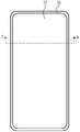
- FIG. 1ais a front view of an electronic device provided by some embodiments of the present application.
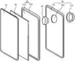
- Fig. 1bis an exploded view of the electronic device shown in Fig. 1a;
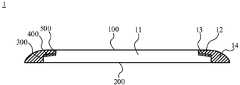
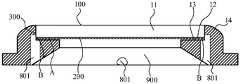
- Fig. 1cis a schematic cross-sectional structure diagram of the electronic device shown in Fig. 1a along the A-A direction;
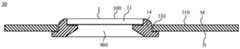
- FIG. 2ais a schematic cross-sectional structural diagram of a cover structure provided by some embodiments of the present application.
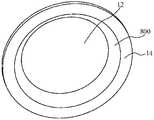
- FIG. 2bis a perspective view of a cover structure provided by further embodiments of the present application.
- FIG. 3is a perspective view of a glass cover plate in a cover structure provided by some embodiments of the present application.
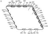
- FIG. 4is a perspective view of a cover body structure obtained after the plastic edge portion is formed on the edge of the glass cover plate when the glass cover plate shown in FIG. 3 is positioned by at least three positioning posts and one ejector pin;
- FIG. 5is a cross-sectional view of the cover structure shown in FIG. 4;
- Fig. 6shows that the plastic edge part is switched to be clamped by the outer surface and the inner surface of the glass cover plate by a structure such as a vacuum suction cup or a hard glue after the glass cover plate shown in Fig. 3 is positioned by at least three positioning posts and one ejector pin When the glass cover plate is formed, the three-dimensional view of the cover body structure obtained by molding on the edge of the glass cover plate;
- a structuresuch as a vacuum suction cup or a hard glue
- FIG. 7is a perspective view of a glass cover plate in a cover body structure provided by further embodiments of the present application.
- FIG. 8is a schematic cross-sectional structural diagram of a cover structure provided by further embodiments of the present application.
- FIG. 9is a perspective view of the cover structure obtained by molding the plastic edge portion on the edge of the glass cover when the glass cover is positioned by at least three positioning posts and one ejector in the cover structure shown in FIG. 8 ;
- Fig. 10shows that after the plastic edge portion of the glass cover in the cover structure shown in Fig. 8 is positioned by at least three positioning posts and one ejector pin, it is switched to the outer surface of the glass cover by a structure such as a vacuum suction cup or a hard glue A three-dimensional view of the cover structure obtained by molding on the edge of the glass cover when the glass cover is clamped with the inner surface;
- FIG. 11is a schematic cross-sectional structural diagram of a cover structure provided by further embodiments of the present application.
- FIG. 12is a schematic cross-sectional structural diagram of a cover structure provided by further embodiments of the present application.
- FIG. 13is a perspective view of the cover structure obtained after the plastic edge portion is formed on the edge of the glass cover when the glass cover of the cover structure shown in FIG. 12 is positioned by at least three positioning posts and one ejector pin;
- FIG. 14is a schematic cross-sectional structural diagram of the cover structure shown in FIG. 13;
- Fig. 15shows that the plastic edge portion of the glass cover of the cover structure shown in Fig. 12 is positioned by at least three positioning posts and one ejector pin, and then switches to a structure such as a vacuum suction cup or a hard glue.
- a perspective view of the cover body structureobtained by molding on the edge of the glass cover plate when the inner surface clamps the glass cover plate;
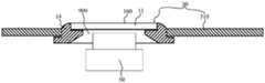
- FIG. 16is a schematic structural diagram when the cover structure shown in FIG. 12 is applied to the back cover in the electronic device shown in FIGS. 1a-1c;
- Fig. 17is another structural schematic diagram when the cover structure shown in Fig. 12 is applied to the back cover in the electronic device shown in Figs. 1a-1c;
- FIG. 18is a schematic cross-sectional structure diagram of an electronic device provided by some embodiments of the present application.
- first and secondare only used for description purposes, and cannot be understood as indicating or implying relative importance or implying the number of indicated technical features.
- a feature defined as “first” or “second”may expressly or implicitly include one or more of that feature.
- the present applicationprovides an electronic device, which may be a portable electronic device or other suitable electronic device.
- the electronic devicemay be a laptop computer, a tablet computer, a smaller device such as a cell phone, a watch, a pendant device or other wearable or miniature device, a cellular phone, a media player, and the like.
- FIG. 1ais a front view of an electronic device provided by some embodiments of the present application
- FIG. 1bis an exploded view of the electronic device shown in FIG. 1a
- FIG. 1cis an A-A direction of the electronic device shown in FIG. 1a.
- the electronic deviceis a mobile phone.
- the electronic deviceincludes a front cover 10 , a middle frame 20 , a back cover 30 , a display module 40 and a camera module 50 .
- the middle frame 20includes a middle plate 210 and a frame 220 arranged around the edge of the middle plate 210.
- the front cover 10 and the back cover 30are stacked on opposite sides of the middle plate 210 and are fixed to the frame 220.
- Cover 30 and bezel 220form part of the housing of the electronic device.
- the display module 40is used for displaying images or videos.
- the display module 40is attached to the surface of the front cover plate 10 close to the middle plate 210 , and the display surface of the display module 40 faces the front cover plate 10 .
- the front cover plate 100is used for The display module 40 is protected and the image light of the display module 40 is transmitted.
- the camera module 50is a rear camera module, and the camera module 50 is disposed between the middle plate 210 and the back cover 30 .
- the size of the camera module 50 along the optical axis directionis difficult to reduce due to the limitation of the structural complexity.
- the back cover 30includes a back cover body 310, the back cover body 310 is provided with an opening 330, and the object side end of the camera module 50 (that is, the camera module 50 is close to the One end of the photographed scene) extends into the opening 330 .
- the back cover 30further includes a decorative cover 320 , the decorative cover 320 is installed at the opening 330 and fixed with the edge of the back cover at the opening 330 , and the decorative cover 320 covers the camera module.
- the decorative cover 320is provided with a light-transmitting area, and the light-transmitting area is opposite to the light incident surface of the camera module 50 .
- the decorative cover 320also forms part of the housing of the electronic device.
- the coveris composed of the glass cover plate and the plastic edge part arranged on the edge of the glass cover plate.
- the bulk structurehas been widely used in the above-mentioned electronic devices shown in Figs. 1a-1c.
- the front cover 10is composed of a transparent glass cover and a plastic edge portion disposed on the edge of the glass cover.
- the plastic edgeis used to meet the 2.5D or 3D appearance design requirements of the front cover 10 .
- the decorative cover 320is composed of a glass cover plate and a plastic edge portion arranged around the edge of the glass cover plate. The gap between the perimeter of the edge and the perimeter of the back cover at the opening 330 .
- the glass cover plate and the plastic edge portioncan be separately formed, and then the glass cover plate and the plastic edge portion with a predetermined shape are assembled together by gluing. .
- thisoften results in a gap between the glass cover plate and the plastic frame due to the limitation of machining accuracy or assembly accuracy, so that it is difficult to ensure the appearance of the cover structure.
- the plastic edge portioncan be directly molded on the edge of the glass cover plate through the injection molding process, so as to match the edge size of the glass cover plate through the molten plastic material with an indeterminate shape, so as to avoid the plastic edge portion and the edge of the glass cover plate.
- the cover structureconstitutes a part of the housing of the electronic device, specifically, the cover
- the structurecan be a front cover of an electronic device, or a decorative cover of a camera module of an electronic device, which is not specifically limited here.
- FIG. 2ais a schematic cross-sectional structure diagram of a cover structure 1 according to some embodiments of the present application.
- the cover structure 1includes a glass cover plate 11, a first ink layer 12, a first adhesive layer 13 and a plastic edge portion 14. .
- the material of the glass cover plate 11is glass, and the shape of the glass cover plate 11 includes but is not limited to a circular plate shape, an oval plate shape, a triangular plate shape, a square plate shape and a polygonal plate shape.
- the cover glass 11includes opposing outer surfaces 100 and inner surfaces 200 and a first side surface 300 located between an edge perimeter of the outer surface 100 and an edge perimeter of the inner surface 200 .
- the outer surface 100refers to the surface facing the outside of the electronic device when the cover glass 11 is applied to the electronic device, and the outer surface 100 is flat.
- the inner surface 200refers to a surface facing the inside of the electronic device when the cover glass 11 is applied to the electronic device, and the inner surface 200 is a plane parallel to the outer surface 100 .
- the first side surface 300is an annular surface surrounding the edge of the outer surface 100 (or the inner surface 200 ). 200) tilt, which is not specifically limited here. In the embodiment shown in FIG. 2a, the first side surface 300 is perpendicular to the outer surface 100 (or the inner surface 200), which should not be considered as a special limitation to the present application.
- the edge of the first side surface 300 close to the outer surface 100may be in contact with the edge of the outer surface 100 around the circumference, or may be spaced from a part of the edge of the outer surface 100 through an intermediate plane, or may pass through the edge of the outer surface 100 around the circumference.
- the interval between the intermediate planesis not specifically limited here.
- the edge of the first side surface 300 close to the outer surface 100 and the edge of the outer surface 100are separated by a middle surface composed of the first step surface 400 and the second side surface 500, which is not It should not be considered as a special limitation on this application.
- the edge of the first side surface 300 that is close to the inner surface 200may be in contact with the edge of the inner surface 200 for a circumference, or may be spaced from a part of the edge of the inner surface 200 through a middle plane, or may be connected to the edge of the inner surface 200 There is no specific limitation on the interval passing through the middle plane between one week.
- the edge of the first side surface 300 close to the inner surface 200is in contact with the edge of the inner surface 200 in a circle, which should not be considered as a special limitation to the present application.
- the edge region of the outer surface 100 , the middle surface between the outer surface 100 and the first side surface 300 , the first side surface 300 , the middle surface between the first side surface 300 and the inner surface 200 , and the inner surface 200The edge area of forms the edge of the glass cover plate 11 .
- the first ink layer 12may be at least one of a black ink layer, a color ink layer, a white ink layer and a transparent ink layer, which is not specifically limited herein.
- the first ink layer 12is disposed at least on the edge of the glass cover plate 11 , that is to say, the first ink layer 12 can be disposed only on the edge of the glass cover plate 11 , and the first ink layer 12 can also be disposed on the edge of the glass cover plate 11 . At the same time as the edge, it is also arranged in other areas of the glass cover 11 , such as the middle area of the inner surface 200 .
- the portion of the first ink layer 12 disposed on the edge of the glass cover plate 11may be disposed on a partial region of the edge of the glass cover plate 11, such as the edge region of the outer surface 100, the middle surface between the outer surface 100 and the first side surface 300, The middle surface between the first side surface 300 and the inner surface 200 or the edge region of the inner surface 200 may also be provided in the entire region of the edge of the glass cover plate 11 , which is not specifically limited here.
- the first ink layer 12can be disposed at least on the edge of the glass cover plate 11 by at least one of glass direct molding (GDM) process, silk screen printing process and pad printing process, which is not limited herein.
- GDMglass direct molding
- the first adhesive layer 13is disposed on the first ink layer 12 on the edge of the glass cover plate 11.
- the first adhesive layer 13can be formed by a blade coating process, a roll coating process, a dip coating process and a spray coating process. At least one is disposed on the first ink layer 12 at the edge of the glass cover plate 11, which is not specifically limited here.
- the material of the plastic edge portion 14includes, but is not limited to, at least one of polyethylene terephthalate (PET), polyphenylene sulfide (PPS) and polyethylene (PE). .
- PETpolyethylene terephthalate
- PPSpolyphenylene sulfide
- PEpolyethylene
- the plastic edge portion 14is formed on at least the first adhesive layer 13 on the edge of the glass cover plate 11 through an injection molding process, that is, the plastic edge portion 14 is formed on the edge of the glass cover plate 11 through an injection molding process, and the At least partially covering the first adhesive layer 13 .
- the plastic edge portion 14can be formed on one edge of the glass cover plate 11 , the opposite two side edges or the adjacent three side edges, or can be formed around the edge of the glass cover plate 11 , which is not specifically limited here.
- the plastic edge portion 14is formed around the edge of the glass cover plate 11 by an injection molding process, which should not be considered as a special limitation to the present application.
- the injection molding process of the plastic edge portion 14can be as follows: firstly, the glass cover plate 11 provided with the first ink layer 12 and the first adhesive layer 13 is carried and fixed at a preset position on the injection molding machine; secondly, the injection mold ( That is, the mold clamping process), to enclose a mold cavity whose shape is consistent with the contour shape of the plastic edge portion 14, and connect the mold cavity with the edge of the glass cover plate 11; then, the molten plastic is injected into the mold cavity by means of pressure.
- the molten plastic materialis bonded to at least the first adhesive layer 13 on the edge of the glass cover 11 ; finally, the plastic material is cooled to realize the solidification of the plastic material, and the solidified plastic material is the plastic edge portion 14 .
- the plastic edge portion 14is formed on at least the first adhesive layer 13 on the edge of the glass cover plate 11 through an injection molding process, and during the injection molding process, the molten plastic material contacts the first adhesive layer 13, so in order to avoid the first adhesive layer 13
- the layer 13loses its viscosity during the injection molding process, and the first adhesive layer 13 should be an adhesive layer with adhesiveness at least at the injection temperature of the plastic edge portion 14 (ie, the temperature of the molten plastic material).
- the first adhesive layer 13is an adhesive layer that is viscous at least at a temperature of 380°C-400°C.
- the first adhesive layer 13may be an adhesive layer that is viscous at all temperatures, or may be an adhesive layer that is viscous only at the injection temperature of the plastic edge portion 14 , or may be an adhesive layer that includes the injection temperature of the plastic edge portion 14 .
- the adhesive layer with viscosity in a larger temperature rangeis not specifically limited here.
- the first adhesive layer 13is a heat-activated adhesive layer
- the heat-activated adhesive layeris a type of adhesive layer that is fluid and viscous at higher temperatures, and solid and non-viscous at lower temperatures
- the heat-activated adhesive layeris in a fluid state and has viscosity at a temperature of 200°C to 400°C, and is solid and non-viscous at a temperature of 0°C to 40°C.
- the first adhesive layer 13is activated in a first temperature range, at which time the first adhesive layer 13 has viscosity, and the first temperature range includes the injection molding temperature of the plastic edge portion 14 .
- the first temperature rangecan be It only includes the injection temperature of the plastic edge portion 14 , and may also be a larger temperature range including the injection temperature of the plastic edge portion 14 , which is not specifically limited here.
- the first adhesive layer 13is cured in a second temperature range, and the maximum temperature value of the second temperature range is smaller than the minimum temperature value of the first temperature range.
- the first adhesive layer 13can be heated or cooled to the second temperature range to cure the first adhesive layer 13 Therefore, it is convenient to transfer the glass cover plate 11 provided with the first ink layer 12 and the first adhesive layer 13 to the injection molding machine, so as to avoid bad phenomena such as bonding with other equipment and being scraped off during the transfer.
- the specific values of the first temperature range and the second temperature rangeare not limited, as long as the first temperature range includes the injection temperature of the plastic edge portion 14, the maximum temperature value of the second temperature range is smaller than the first temperature range the minimum temperature value.
- the second temperature range of the first adhesive layer 13includes a temperature range in a normal temperature state. In this way, after the first adhesive layer 13 is disposed on the first ink layer 12 at the edge of the glass cover plate 11 , the first adhesive layer 13 only needs to be cooled to room temperature, and then the first adhesive layer 13 can be cured, and the first adhesive layer 13 can be cured by During the transportation, no other heating or cooling equipment is needed to maintain the temperature of the first adhesive layer 13, so that the first adhesive layer 13 is kept in a solidified state during the transportation.
- the material of the first adhesive layer 13may include at least one of silicone-based adhesives, phenolic resin adhesives, urea-formaldehyde resin adhesives, temperature-resistant epoxy adhesives, and polyimide adhesives, which are not specifically limited herein.
- the plastic edge portion 14is formed on at least the first adhesive layer 13 around the edge of the glass cover plate 11 through the injection molding process, and during the injection molding process, the molten plastic material contacts the first adhesive layer 13, the An ink layer 12 is adjacent to the first adhesive layer 13, and the temperature of the plastic material in the molten state is inevitably conducted to the first ink layer 12. Therefore, in order to prevent the first ink layer 12 from discoloring due to heat, the temperature of the plastic material in the molten state is transferred from the glass cover 11.
- the first ink layer 12should be an ink layer capable of withstanding the injection temperature of the plastic edge portion 14 in case of unfavorable phenomena such as falling off.
- the first ink layer 12is an ink layer that can withstand a temperature of 400°C; for another example, if the injection temperature of the plastic edge portion 14 is 380°C, then the first ink layer 12 is an ink layer that can withstand a temperature of 400°C.
- the ink layer 12is an ink layer that can withstand a temperature of 380°C.
- the plastic edge portion 14is formed on the edge of the glass cover plate 11 through an injection molding process, in this process, the molten plastic material without a specific shape is used to match the edge size of the glass cover plate 11, so that the The outer surface of the plastic edge portion 14 is continuously connected with the outer surface of the glass cover plate 11 , so that the appearance of the cover structure 1 can be ensured.
- the bonding force between the ink layer and the glass per unit areais greater than the unit bonding area between the plastic and the glass when the plastic is directly molded on the glass by the injection molding process It can be seen that the bonding force between the first ink layer 12 and the glass cover plate 11 is relatively large. Further, the first adhesive layer 13 is disposed on the first ink layer 12 on the edge of the glass cover plate 11 , the bonding force between the adhesive layer and the ink per unit area is also greater than the bonding force between the plastic and the glass at the unit bonding area when the plastic is directly molded on the glass by the injection molding process.
- the first adhesive layer 13 and the first The bonding force between the ink layers 12is relatively large. Furthermore, the plastic edge portion 14 is formed on at least the first adhesive layer 13 on the edge of the glass cover 11 through an injection molding process. The force is greater than the bonding force between the plastic and the glass at the unit bonding area when the plastic is directly molded on the glass by the injection molding process. Therefore, the bonding force between the plastic edge portion 14 and the first adhesive layer 13 is relatively large. To sum up the above , the bonding force per unit area of the bonding surfaces of the different media between the edge of the glass cover 11 and the plastic edge 14 is greater than the bonding force between the plastic and the glass at the unit bonding area when the plastic is directly molded on the glass by the injection molding process. Therefore, the structural strength of the cover structure 1 provided in the embodiment of the present application is relatively high.
- the edge of the glass cover plate 11can have various structural forms.
- the arrangement positions of the first ink layer 12 , the first adhesive layer 13 and the plastic edge portion 14are also different.
- the edge structure of the cover plate 11 and the arrangement positions of the first ink layer 12 , the first adhesive layer 13 and the plastic edge portion 14may include the following Embodiments 1 to 3.
- Embodiment 1Please continue to refer to FIG. 2a, except that the glass cover 11 includes an outer surface 100, an inner surface 200, and a first side 300 located between the edge of the outer surface 100 and the edge of the inner surface 200, the glass cover The board 11 also includes a first stepped surface 400 and a second side surface 500 .
- the first step surface 400 and the second side surface 500are formed by milling cutters on a computer numerical control (CNC) machine tool.
- CNCcomputer numerical control
- the first stepped surface 400is located outside the edge of the outer surface 100 , that is, the first stepped surface 400 is located on the side of the edge of the outer surface 100 away from the center of the outer surface 100 .
- the first stepped surface 400may be a smaller surface located outside one edge of the outer surface 100 , or may be a larger annular surface disposed around the edge of the outer surface 100 , which is not specifically limited herein.
- the first stepped surface 400is an annular surface provided around the edge of the outer surface 100, which should not be considered as a special limitation to the present application.
- Both the first step surface 400 and the outer surface 100face the side of the plane where the outer surface 100 is located and away from the plane where the inner surface 200 is located. Part of the space on the side of the plane where 200 is located is the outer space of the glass cover plate 11 , and the first stepped surface 400 and the outer surface 100 are both opposite to the outer space of the glass cover plate 11 .
- the first stepped surface 400has an outer edge disposed away from the center of the outer surface 100 and an inner edge disposed near the center of the outer surface 100 .
- the outer edge of the first stepped surface 400is connected with the edge of the first side surface 300 close to the outer surface 100
- the second side surface 500is connected between the inner edge of the first stepped surface 400 and the outer surface 100 .
- the distance from the first stepped surface 400 to the inner surface 200is smaller than the distance from the outer surface 100 to the inner surface 200 . distance.
- the first stepped surface 400may be a plane or a curved surface, which is not specifically limited herein.
- the first stepped surface 400may be parallel to the outer surface 100 (or the inner surface 200), or may be inclined relative to the outer surface 100 (or the inner surface 200), which is not specifically limited herein.
- the second side surface 500may be a plane or a curved surface, which is not specifically limited herein.
- the second side surface 500may be perpendicular to the outer surface 100 (or the inner surface 200 ), or may be inclined relative to the outer surface 100 (or the inner surface 200 ), which is not specifically limited herein.
- the first ink layer 12is disposed at least on the first stepped surface 400
- the first adhesive layer 13is disposed at least on the first ink layer 12 of the first stepped surface 400
- the plastic edge portion 14is formed at least on the first side surface 300 by an injection molding process. , on the first adhesive layer 13 and the second side surface 500 of the first step surface 400 .
- the plastic edge portion 14is formed on the first side surface 300 , the first adhesive layer 13 and the second side surface 500 of the first stepped surface 400 through the injection molding process, the outer surface of the plastic edge portion 14 can be formed with the glass The outer surfaces of the cover plates 11 are continuously connected, so that the appearance refinement of the cover structure 1 can be ensured.
- the first stepped surface 400 and the outer surface 100are both facing the side of the plane where the outer surface 100 is located away from the plane where the inner surface 200 is located, and because the first ink layer 12 is disposed on the first stepped surface 400, The first adhesive layer 13 is disposed on the first ink layer 12 of the first step surface 400 , so it is convenient for the first ink layer 12 and the first adhesive layer 13 to be disposed on the edge of the glass cover 11 .
- the plastic edge portion 14is formed on the first side surface 300 of the edge of the glass cover 11 , the first adhesive layer 13 and the second side surface 500 of the first stepped surface 400 through the injection molding process, the plastic edge portion 14 is formed.
- the plastic edge portion 14can apply a direction to the inner side of the glass cover 11 (that is, where the inner surface 200 is located) to the glass cover 11 .
- the force of the plane away from the side of the plane where the outer surface 100 is located)prevents the glass cover 11 from falling off from the plastic edge portion 14 .
- the edge of the first side surface 300 close to the inner surface 200may be in contact with the edge of the inner surface 200 in a circle, or may be spaced from at least part of the edge of the inner surface 200 through a middle plane, which is not specifically limited here.
- the connection form between the first side surface 300 and the inner surface 200 and the arrangement positions of the first ink layer 12 , the first adhesive layer 13 and the plastic edge portion 14may include the following first to third implementations .
- the first implementation mannerplease continue to refer to FIG. 2 a , the edge of the first side surface 300 close to the inner surface 200 is directly connected with the edge of the inner surface 200 around the circumference.
- FIG. 2bis a perspective view of a cover structure 1 according to further embodiments of the present application.
- At least one positioning groove 201is provided in the middle region of the inner surface 200 of the glass cover plate 11, and the at least one positioning groove 201 is used for Cooperate with the positioning column on the injection molding machine to fix the glass cover plate 11 with the first ink layer 12 and the first adhesive layer 13 to the preset position on the injection molding machine, so as to facilitate subsequent molding on the edge of the glass cover plate 11 Operation of the plastic edge portion 14 .
- the positioning groove 201may be a through groove penetrating the glass cover plate 11 or a groove not penetrating the glass cover plate 11 , which is not specifically limited herein.
- the positioning slot 201can be a rectangular slot, a square slot, a triangular slot, a circular slot, a waist-shaped slot, etc.
- FIG. 2bonly shows an example in which the positioning slot 201 is a rectangular slot, which cannot be regarded as a special limitation to the present application. .
- the number of the positioning grooves 201may be one or multiple.
- FIG. 2bonly shows an example of the number of the positioning grooves 201 being one, which should not be considered as a special limitation to the present application.
- the positioning grooves 201are circular grooves, in order to realize the positioning of the glass cover plate 11 , the number of the positioning grooves 201 needs to be multiple.
- the positioning groove 201is a through groove passing through the glass cover plate 11, after the plastic edge portion 14 is formed on the edge of the glass cover plate 11, the positioning groove 201 needs to be filled with a transparent material to ensure that the glass Appearance of the cover plate 11 .
- FIG. 3is a perspective view of the cover glass 11 in the cover structure 1 provided by some embodiments of the application.
- the cover glass 11further includes a second stepped surface 600 and a third side surface 700 .
- the second step surface 600 and the third side surface 700are formed by milling cutters on a computer numerical control (CNC) machine tool.
- CNCcomputer numerical control
- the second stepped surface 600is located outside the edge of the inner surface 200 , that is, the second stepped surface 600 is located on the side of the edge of the inner surface 200 away from the center of the inner surface 200 .
- the second stepped surface 600may be a smaller surface located outside one edge of the inner surface 200 , or may be a larger annular surface disposed around the edge of the inner surface 200 , which is not specifically limited herein. In the embodiment shown in FIG. 3 , the second step surface 600 is a smaller surface located outside one side edge of the inner surface 200 , which should not be considered as a special limitation to the present application.
- the number of the second stepped surface 600may be one or multiple, which is not specifically limited herein.
- the number of the second stepped surfaces 600is plural, the plural second stepped surfaces 600 are arranged along the edge of the inner surface 200 .
- the number of the plurality of second step surfaces 600may be 3, 4, 5, 8, 10, 16, etc., which are not specifically limited herein.
- FIG. 3only shows an example in which the number of the second step surfaces 600 is 4, which should not be considered as a special limitation to the present application.
- FIG. 7is a perspective view of the glass cover plate 11 in the cover structure 1 provided by other embodiments of the present application, and the number of the plurality of second stepped surfaces 600 is 16. As shown in FIG.
- Both the second step surface 600 and the inner surface 200face the side of the plane where the inner surface 200 is located away from the plane where the outer surface 100 is located. Part of the space on the side of the plane where 100 is located is the inner space of the glass cover plate 11 , and the second step surface 600 and the inner surface 200 are both opposite to the inner space of the glass cover plate 11 .
- the second stepped surface 600has an outer edge disposed away from the center of the inner surface 200 and an inner edge disposed close to the center of the inner surface 200 .
- the outer edge of the second stepped surface 600is connected to the edge of the first side surface 300 close to the inner surface 200
- the third side surface 700is connected between the inner edge of the second stepped surface 600 and the inner surface 200 .
- the distance from the second stepped surface 600 to the outer surface 100is smaller than the distance from the inner surface 200 to the outer surface 100 . distance.
- the third side surface 700is also an annular surface disposed around the edge of the inner surface 200 .
- each third side surface 700is connected between the inner edge of the second stepped surface 600 corresponding to the third side surface 700 and the inner surface 200 .
- the second stepped surface 600is a smaller surface located outside one edge of the inner surface 200 and the number of the second stepped surface 600 is multiple
- the outer edges of the multiple second stepped surfaces 600are all connected to the first side surface 300 .
- the number of the third side surfaces 700is also multiple
- the number of the multiple third side surfaces 700is equal to the number of the multiple second stepped surfaces 600
- the number of the multiple third side surfaces 700is the same as the number of the multiple second stepped surfaces 600 .
- each third side surface 700is connected between the inner edge of the second stepped surface 600 corresponding to the third side surface 700 and the inner surface 200 .
- the number of the second step surfaces 600is four, and the number of the third side surfaces 700 is also four.
- the number of the second step surfaces 600is 16, and the number of the third side surfaces 700 is also 16.
- the grooves surrounded by the second stepped surface 600 and the third side surface 700 corresponding to the second stepped surface 600include but are not limited to rectangular grooves, square grooves, semicircular grooves and dovetail grooves, which are not specifically limited herein.
- the second stepped surface 600may be a plane or a curved surface, which is not specifically limited herein.
- the second stepped surface 600may be parallel to the inner surface 200 (or the outer surface 100 ), or may be inclined relative to the inner surface 200 (or the outer surface 100 ), which is not specifically limited herein.
- the third side surface 700may be a plane or a curved surface, which is not specifically limited herein.
- the third side surface 700may be perpendicular to the inner surface 200 (or the outer surface 100 ), or may be inclined relative to the inner surface 200 (or the outer surface 100 ), which is not specifically limited herein.
- the plastic edge portion 14is also formed on the second stepped surface 600 and the third side surface 700 by an injection molding process.
- the second step surface 600 and the third side surface 700can increase the bonding area between the plastic edge portion 14 and the glass cover plate 11 , thereby further increasing the bonding area between the plastic edge portion 14 and the glass cover plate 11 .
- the bonding forceimproves the structural strength of the cover structure 1 .
- the second step surface 600 and the third side surface 700can also cooperate with the positioning column to realize the positioning of the glass cover plate 11 on the injection molding machine.
- the second stepped surface 600is a smaller surface outside one edge of the inner surface 200, and the number of the second stepped surface 600 and the third side surface 700 is multiple, in order to make the second stepped surface 600 and the third The side surface 700 can cooperate with the positioning column on the injection molding machine to realize the positioning of the glass cover plate 11 .
- the plurality of second stepped surfaces 600include at least three second stepped surfaces evenly arranged around the edge of the inner surface 200 600. In this way, the top surfaces of the at least three positioning posts on the injection molding machine are respectively fitted with the at least three second stepped surfaces 600 , and the side surfaces of the at least three positioning posts are respectively fitted with the at least three second stepped surfaces 600 .
- the position of the glass cover plate 11 on the plane where it is locatedcan be fixed.
- a mandrelis added to the side of the outer surface 100 of the glass cover plate 11 away from the inner surface 200 , and the top surface of the mandrel is attached to the outer surface 100 of the glass cover plate 11 , so that the glass cover can be realized.
- the cover plate 11is fixed at a position perpendicular to the plane where the cover plate 11 is located, thereby realizing positioning.
- This positioning methodis simple and easy to implement.
- the shape of the positioning column on the injection molding machineis not limited to cylindrical, rectangular or other regular or irregular profiling structures.
- the positioning of the glass cover plate 11can be realized by three positioning columns and one ejector rod.
- the shape of the glass coveris a square plate shape or a rectangular plate shape, the positioning of the glass cover plate 11 can only be achieved through four positioning columns and one ejector rod.
- the plastic edge portion 14can be formed on the edge of the glass cover 11 when the glass cover 11 is positioned by at least three positioning posts and one ejector pin, or can be formed on the edge of the glass cover 11 when the glass cover 11 is positioned by at least three positioning pins and one ejector. After the rod is positioned, it is switched to clamp the glass cover 11 by the outer surface 100 and the inner surface 200 of the glass cover 11 by a vacuum suction cup or hard glue, etc., and then molded on the edge of the glass cover 11, which is not specifically limited here. .
- FIG. 4shows the cover body structure 1 obtained by molding the plastic edge portion 14 on the edge of the glass cover plate 11 when the glass cover plate 11 shown in FIG. 3 is positioned by at least three positioning posts and one ejector pin.
- the plastic edge portion 14has an inner surface 800.
- the inner surface 800 of the plastic edge portion 14refers to the surface of the plastic edge portion 14 facing the interior of the electronic device when the cover structure 1 is used as a part of the housing of the electronic device.
- the inner surface 800 of the part 14is provided with second positioning post extraction holes 802 at positions corresponding to the at least three second stepped surfaces 600 .
- FIG. 5is a cross-sectional view of the cover structure 11 shown in FIG.
- the second positioning post extraction hole 802extends in a direction perpendicular to the glass cover plate 11 , and the second step surface 600 and the second step The third side surface 700 connected by the surface 600 forms part of the inner surface area of the second positioning post extraction hole 802 .
- FIG. 6shows that after the glass cover 11 shown in FIG. 3 is positioned by at least three positioning posts and one ejector pin, the plastic edge portion 14 is switched to the glass cover 11 by the vacuum suction cup or hard glue.
- the outer surface 100 and the inner surface 200 of the glass cover plate 11are sandwiched between the outer surface 100 and the inner surface 200, the three-dimensional view of the cover body structure 1 obtained by molding on the edge of the glass cover plate 11 is obtained.
- the positioning of the at least three positioning posts and one ejector pin on the glass cover plate 11is cancelled.
- the inner surface 800 of the edge portion 14does not have a positioning post extraction hole, thereby ensuring the surface integrity and structural strength of the cover structure 1 .
- the second stepped surface 600is an annular surface disposed around the edge of the inner surface 200
- the third side surface 700is also an annular surface disposed around the edge of the inner surface 200
- the second stepped surface 600includes at least three stepped surface areas evenly arranged around the edge of the inner surface 200 . In this way, the top surfaces of the at least three positioning columns on the injection molding machine are respectively attached to the at least three stepped surface areas, and at the same time, the side surfaces of the at least three positioning columns are connected to the at least three stepped surface areas.
- the position of the glass cover plate 11 on the plane where it is locatedcan be fixed by fitting the partial areas of the side surfaces.
- a mandrelis added to the side of the outer surface 100 of the glass cover plate 11 away from the inner surface 200 , and the top surface of the mandrel is attached to the outer surface 100 of the glass cover plate 11 , so that the glass cover can be realized.
- the cover plate 11is fixed at a position perpendicular to the plane where the cover plate 11 is located, thereby realizing positioning. This positioning method is simple and easy to implement.
- the plastic edge portion 14can be formed on the edge of the glass cover 11 when the glass cover 11 is positioned by at least three positioning posts and one ejector pin, or can be formed on the edge of the glass cover 11 when the glass cover 11 is positioned by at least three positioning pins and one ejector. After the rod is positioned, the glass cover 11 is clamped by the outer surface and the inner surface of the glass cover 11 by a vacuum suction cup or hard glue, and then is formed on the edge of the glass cover 11 , which is not limited herein.
- the inner surface of the plastic edge portion 14corresponds to the cover body structure 1 .
- the positions of at least three stepped surface areasare provided with second positioning post extraction holes.
- the second positioning post extraction holeextends along a direction perpendicular to the glass cover plate 11 , and a part of the third side surface area connected to the stepped surface area forms a part of the inner surface area of the second positioning post extraction hole.
- the plastic edge portion 14is switched to clamp the glass cover 11 by the outer surface and the inner surface of the glass cover 11 by a vacuum suction cup or hard glue.
- the cover structure 1 obtained by molding on the edge of the glass cover 11there is no positioning post extraction hole on the inner surface 800 of the plastic edge portion 14 , thereby ensuring the surface integrity and structural strength of the cover structure 1 .
- the third implementation manneran edge of the first side surface 300 close to the inner surface 200 and at least a part of the edge of the inner surface 200 are spaced by a middle plane.
- FIG. 8is a schematic cross-sectional structure diagram of the cover structure 1 provided by further embodiments of the present application.
- the glass cover plate 11further includes a second stepped surface 600 and a third side surface 700 .
- the second step surface 600 and the third side surface 700are formed by milling cutters on a computer numerical control (CNC) machine tool.
- CNCcomputer numerical control
- the second stepped surface 600is located outside the edge of the inner surface 200 , that is, the second stepped surface 600 is located on the side of the edge of the inner surface 200 away from the center of the inner surface 200 .
- the second stepped surface 600may be a smaller surface located outside one edge of the inner surface 200 , or may be a larger annular surface disposed around the edge of the inner surface 200 , which is not specifically limited herein.
- the number of the second stepped surface 600may be one or multiple, which is not specifically limited herein.
- the plural second stepped surfaces 600are arranged along the edge of the inner surface 200 .
- the second stepped surface 600is an annular surface disposed around the edge of the inner surface 200 , which should not be considered as a special limitation to the present application.
- Both the second step surface 600 and the inner surface 200face the side of the plane where the inner surface 200 is located away from the plane where the outer surface 100 is located. Part of the space on the side of the plane where 100 is located is the inner space of the glass cover plate 11 , and the second step surface 600 and the inner surface 200 are both opposite to the inner space of the glass cover plate 11 .
- the second stepped surface 600has an outer edge disposed away from the center of the inner surface 200 and an inner edge disposed close to the center of the inner surface 200 .
- the outer edge of the second stepped surface 600is connected to the edge of the first side surface 300 close to the inner surface 200
- the third side surface 700is connected between the inner edge of the second stepped surface 600 and the inner surface 200 .
- the distance from the second stepped surface 600 to the outer surface 100is smaller than the distance from the inner surface 200 to the outer surface 100 . distance.
- the outer edges of the multiple second stepped surfaces 600are all connected to the first side surface 300 .
- the number of the third side surfaces 700is also multiple, the number of the multiple third side surfaces 700 is equal to the number of the multiple second stepped surfaces 600 , and the number of the multiple third side surfaces 700 is the same as the number of the multiple second stepped surfaces 600 .
- each third side surface 700is connected between the inner edge of the second stepped surface 600 corresponding to the third side surface 700 and the inner surface 200 .
- the third side surface 700is also an annular surface disposed around the edge of the inner surface 200 .
- the second stepped surface 600may be a plane or a curved surface, which is not specifically limited herein.
- the second stepped surface 600may be parallel to the inner surface 200 (or the outer surface 100 ), or may be inclined relative to the inner surface 200 (or the outer surface 100 ), which is not specifically limited herein.
- the third side surface 700may be a plane or a curved surface, which is not specifically limited herein.
- the third side surface 700may be perpendicular to the inner surface 200 (or the outer surface 100 ), or may be inclined relative to the inner surface 200 (or the outer surface 100 ), which is not specifically limited herein.
- the first ink layer 12is also disposed on the second stepped surface 600
- the first adhesive layer 13is also disposed on the first ink layer 12 of the second stepped surface 600
- the plastic edge portion 14is also formed on the second stepped surface by an injection molding process. 600 on the first adhesive layer 13 and the third side 700 .
- the bonding area between the plastic edge portion 14 and the glass cover 11can be increased through the second step surface 600 and the third side surface 700 , and the first ink layer 12 and the first ink layer 12 on the second step surface 600
- An adhesive layer 13can increase the bonding force per unit area between the plastic edge portion 14 and the second stepped surface 600 , thereby further increasing the bonding force between the plastic edge portion 14 and the glass cover plate 11 and improving the cover structure. 1 structural strength.
- the second step surface 600 and the third side surface 700can also cooperate with the positioning column to realize the positioning of the glass cover plate 11 on the injection molding machine.
- the second stepped surface 600is a smaller surface outside one edge of the inner surface 200, and the number of the second stepped surface 600 and the third side surface 700 is multiple, in order to make the second stepped surface 600 and the third The side surface 700 can cooperate with the positioning column on the injection molding machine to realize the positioning of the glass cover plate 11 .
- the plurality of second stepped surfaces 600include at least three second stepped surfaces evenly arranged around the edge of the inner surface 200 600.
- the top surfaces of the at least three positioning posts on the injection molding machineare respectively attached to the surfaces of the first adhesive layer 13 of the at least three second stepped surfaces 600 , and the side surfaces of the at least three positioning posts are The third side surfaces 700 connected by the three second step surfaces 600 are attached, so that the position of the glass cover plate 11 on the plane where it is located can be fixed.
- a mandrelis added to the side of the outer surface 100 of the glass cover plate 11 away from the inner surface 200 , and the top surface of the mandrel is attached to the outer surface 100 of the glass cover plate 11 , so that the glass cover can be realized.
- the cover plate 11is fixed at a position perpendicular to the plane where the cover plate 11 is located, thereby realizing positioning. This positioning method is simple and easy to implement.
- the plastic edge portion 14can be formed on the edge of the glass cover 11 when the glass cover 11 is positioned by at least three positioning posts and one ejector pin, or can be formed on the edge of the glass cover 11 when the glass cover 11 is positioned by at least three positioning pins and one ejector. After the rod is positioned, it is switched to clamp the glass cover 11 by the outer surface 100 and the inner surface 200 of the glass cover 11 by a vacuum suction cup or hard glue, etc., and then molded on the edge of the glass cover 11, which is not specifically limited here. .
- the inner surface of the plastic edge portion 14has 800 pairs of At least three second step surfaces 600 should be provided with second positioning post extraction holes, the second positioning post extraction holes extend in a direction perpendicular to the glass cover 11 , and the first glue on the second step surface 600
- the third side surface 700 connecting the surface of the layer 13 and the second step surface 600forms part of the inner surface area of the second positioning post extraction hole.
- the plastic edge portion 14is switched to the outer surface 100 and the inner surface 200 of the glass cover plate 11 to clamp the glass cover by a vacuum suction cup or hard glue.
- the inner surface 800 of the plastic edge portion 14does not have a positioning post extraction hole, thereby ensuring the surface integrity and structure of the cover body structure 1 strength.
- the second stepped surface 600is an annular surface disposed around the edge of the inner surface 200
- the third side surface 700is also an annular surface disposed around the edge of the inner surface 200
- the second stepped surface 600includes at least three stepped surface areas evenly arranged around the edge of the inner surface 200 .
- the top surfaces of the at least three positioning posts on the injection molding machineare respectively attached to the surfaces of the first adhesive layer 13 in the at least three stepped surface regions, and at the same time, the side surfaces of the at least three positioning posts are respectively attached to the at least three
- the position of the glass cover plate 11 on the plane where it is locatedcan be fixed by fitting the partial regions of the third side surfaces connected by the step surface regions.
- a mandrelis added to the side of the outer surface 100 of the glass cover plate 11 away from the inner surface 200 , and the top surface of the mandrel is attached to the outer surface 100 of the glass cover plate 11 , so that the glass cover can be realized.
- the cover plate 11is fixed at a position perpendicular to the plane where the cover plate 11 is located, thereby realizing positioning. This positioning method is simple and easy to implement.
- the plastic edge portion 14can be formed on the edge of the glass cover 11 when the glass cover 11 is positioned by at least three positioning posts and one ejector pin, or can be formed on the edge of the glass cover 11 when the glass cover 11 is positioned by at least three positioning pins and one ejector. After the rod is positioned, the glass cover 11 is clamped by the outer surface and the inner surface of the glass cover 11 by a vacuum suction cup or hard glue, and then is formed on the edge of the glass cover 11 , which is not limited herein.
- FIG. 9is obtained by molding the plastic edge portion 14 on the edge of the glass cover 11 when the glass cover 11 in the cover structure 1 shown in FIG. 8 is positioned by at least three positioning posts and one ejector pin.
- the inner surface 800 of the plastic edge portion 14is provided with a second positioning post extraction hole 802 at a position corresponding to the at least three stepped surface regions.
- the second positioning post extraction hole 802extends in a direction perpendicular to the glass cover plate 11 , and the second positioning post extraction hole is formed by the surface of the first adhesive layer 13 in the stepped surface area and the part of the third side surface connected to the stepped surface area. Portion of the inner surface area of the exit hole 802 .
- FIG. 10shows the plastic edge 14 in the cover structure 1 shown in FIG. 8 after the glass cover 11 is positioned by at least three positioning posts and one ejector pin, and then switched to a vacuum suction cup or hard glue, etc. Structure
- the glass cover 11is sandwiched between the outer surface and the inner surface of the glass cover 11, the three-dimensional view of the cover structure 1 obtained by molding on the edge of the glass cover 11, the inner surface 800 of the plastic edge portion 14 has no positioning posts By pulling out the hole, the surface integrity and structural strength of the cover structure 1 can be ensured.
- FIG. 11is a schematic cross-sectional structure diagram of the cover structure 1 provided by some other embodiments of the present application.
- the glass cover 11also includes a second step surface 600 and a first side surface 300. The third side 700 .
- the second step surface 600 and the third side surface 700are formed by milling cutters on a computer numerical control (CNC) machine tool.
- CNCcomputer numerical control
- the second stepped surface 600is located outside the edge of the inner surface 200 , that is, the second stepped surface 600 is located on the side of the edge of the inner surface 200 away from the center of the inner surface 200 .
- the second stepped surface 600may be a smaller surface located outside one edge of the inner surface 200 , or may be a larger annular surface disposed around the edge of the inner surface 200 , which is not specifically limited herein.
- the number of the second stepped surface 600may be one or multiple, which is not specifically limited herein.
- the plural second stepped surfaces 600are arranged along the edge of the inner surface 200 .
- the second stepped surface 600is an annular surface disposed around the edge of the inner surface 200 , which should not be considered as a special limitation to the present application.
- Both the second step surface 600 and the inner surface 200face the side of the plane where the inner surface 200 is located away from the plane where the outer surface 100 is located. Part of the space on the side of the plane where 100 is located is the inner space of the glass cover plate 11 , and the second step surface 600 and the inner surface 200 are both opposite to the inner space of the glass cover plate 11 .
- the second stepped surface 600has an outer edge disposed away from the center of the inner surface 200 and an inner edge disposed close to the center of the inner surface 200 .
- the outer edge of the second stepped surface 600is connected to the edge of the first side surface 300 close to the inner surface 200
- the third side surface 700is connected between the inner edge of the second stepped surface 600 and the inner surface 200 .
- the distance from the second stepped surface 600 to the outer surface 100is smaller than the distance from the inner surface 200 to the outer surface 100 . distance.
- the outer edges of the multiple second stepped surfaces 600are all connected to the first side surface 300 .
- the number of the third side surfaces 700is also multiple, the number of the multiple third side surfaces 700 is equal to the number of the multiple second stepped surfaces 600 , and the number of the multiple third side surfaces 700 is the same as the number of the multiple second stepped surfaces 600 .
- each third side surface 700is connected between the inner edge of the second stepped surface 600 corresponding to the third side surface 700 and the inner surface 200 .
- the third side surface 700is also an annular surface disposed around the edge of the inner surface 200 .
- the second stepped surface 600may be a plane or a curved surface, which is not specifically limited herein.
- the second stepped surface 600may be parallel to the inner surface 200 (or the outer surface 100 ), or may be inclined relative to the inner surface 200 (or the outer surface 100 ), which is not specifically limited herein.
- the third side surface 700may be a plane or a curved surface, which is not specifically limited herein.
- the third side surface 700may be perpendicular to the inner surface 200 (or the outer surface 100 ), or may be inclined relative to the inner surface 200 (or the outer surface 100 ), which is not specifically limited herein.
- the first ink layer 12is disposed on the second stepped surface 600
- the first adhesive layer 13is disposed on the first ink layer 12 of the second stepped surface 600
- the plastic edge portion 14is formed on the first side surface 300 and the second surface by injection molding. on the first adhesive layer 13 and the third side surface 700 of the step surface 600 .
- the plastic edge portion 14is formed on the first side surface 300 , the first adhesive layer 13 and the third side surface 700 of the second stepped surface 600 through the injection molding process, the outer surface of the plastic edge portion 14 can be connected with the glass The outer surfaces of the cover plates 11 are continuously connected, so that the appearance refinement of the cover structure 1 can be ensured.
- the second step surface 600 and the inner surface 200are both facing the side of the plane where the inner surface 200 is located away from the plane where the outer surface 100 is located, and because the first ink layer 12 is disposed on the second step surface 600, The first adhesive layer 13 is disposed on the first ink layer 12 of the second step surface 600 , so it is convenient for the first ink layer 12 and the first adhesive layer 13 to be disposed on the edge of the glass cover plate 11 .
- the second step surface 600 and the third side surface 700can also cooperate with the positioning column to realize the positioning of the glass cover plate 11 on the injection molding machine.
- the second stepped surface 600is a smaller surface outside one edge of the inner surface 200, and the number of the second stepped surface 600 and the third side surface 700 is multiple, in order to make the second stepped surface 600 and the third The side surface 700 can cooperate with the positioning column on the injection molding machine to realize the positioning of the glass cover plate 11 .
- the plurality of second stepped surfaces 600include at least three second stepped surfaces evenly arranged around the edge of the inner surface 200 600.
- the top surfaces of the at least three positioning posts on the injection molding machineare respectively attached to the surfaces of the first adhesive layer 13 of the at least three second stepped surfaces 600 , and the side surfaces of the at least three positioning posts are The third side surfaces 700 connected by the three second step surfaces 600 are attached, so that the position of the glass cover plate 11 on the plane where it is located can be fixed.
- a mandrelis added to the side of the outer surface 100 of the glass cover plate 11 away from the inner surface 200 , and the top surface of the mandrel is attached to the outer surface 100 of the glass cover plate 11 , so that the glass cover can be realized.
- the cover plate 11is fixed at a position perpendicular to the plane where the cover plate 11 is located, thereby realizing positioning. This positioning method is simple and easy to implement.
- the plastic edge portion 14can be formed on the edge of the glass cover 11 when the glass cover 11 is positioned by at least three positioning posts and one ejector pin, or can be formed on the edge of the glass cover 11 when the glass cover 11 is positioned by at least three positioning pins and one ejector. After the rod is positioned, it is switched to clamp the glass cover 11 by the outer surface 100 and the inner surface 200 of the glass cover 11 by a vacuum suction cup or hard glue, etc., and then molded on the edge of the glass cover 11, which is not specifically limited here. .
- the inner surface of the plastic edge portion 14has 800 pairs of At least three second step surfaces 600 should be provided with second positioning post extraction holes, the second positioning post extraction holes extend in a direction perpendicular to the glass cover 11 , and the first glue on the second step surface 600
- the third side surface 700 connecting the surface of the layer 13 and the second step surface 600forms part of the inner surface area of the second positioning post extraction hole.
- the plastic edge portion 14is switched to the outer surface 100 and the inner surface 200 of the glass cover plate 11 to clamp the glass cover by a vacuum suction cup or hard glue.
- the inner surface 800 of the plastic edge portion 14does not have a positioning post extraction hole, thereby ensuring the surface integrity and structure of the cover body structure 1 strength.
- the second stepped surface 600is an annular surface disposed around the edge of the inner surface 200
- the third side surface 700is also an annular surface disposed around the edge of the inner surface 200
- the second stepped surface 600includes at least three stepped surface areas evenly arranged around the edge of the inner surface 200 .
- the top surfaces of the at least three positioning posts on the injection molding machineare respectively attached to the surfaces of the first adhesive layer 13 in the at least three stepped surface regions, and at the same time, the side surfaces of the at least three positioning posts are respectively attached to the at least three
- the position of the glass cover plate 11 on the plane where it is locatedcan be fixed by fitting the partial regions of the third side surfaces connected by the step surface regions.
- a mandrelis added to the side of the outer surface 100 of the glass cover plate 11 away from the inner surface 200 , and the top surface of the mandrel is attached to the outer surface 100 of the glass cover plate 11 , so that the glass cover can be realized.
- the cover plate 11is fixed at a position perpendicular to the plane where the cover plate 11 is located, thereby realizing positioning. This positioning method is simple and easy to implement.
- the plastic edge portion 14can be formed on the edge of the glass cover 11 when the glass cover 11 is positioned by at least three positioning posts and one ejector pin, or can be formed on the edge of the glass cover 11 when the glass cover 11 is positioned by at least three positioning pins and one ejector. After the rod is positioned, the glass cover 11 is clamped by the outer surface and the inner surface of the glass cover 11 by a vacuum suction cup or hard glue, and then is formed on the edge of the glass cover 11 , which is not limited herein.
- the inner surface of the plastic edge portion 14has 800 pairs of A second positioning post extraction hole should be provided at the position of at least three step surface areas.
- the second positioning post extraction holeextends in a direction perpendicular to the glass cover plate 11 , and the second positioning post extraction is formed by the surface of the first adhesive layer 13 in the stepped surface area and the partial area of the third side surface connected to the stepped surface area. Part of the inner surface area of the hole.
- the plastic edge portion 14is switched to clamp the glass cover 11 by the outer surface and the inner surface of the glass cover 11 by a vacuum suction cup or hard glue.
- the cover structure 1 obtained by molding on the edge of the glass cover 11there is no positioning post extraction hole on the inner surface 800 of the plastic edge portion 14 , thereby ensuring the surface integrity and structural strength of the cover structure 1 .
- Embodiment 3Please refer to FIG. 12 , which is a schematic cross-sectional structure diagram of the cover structure 1 provided by some other embodiments of the present application.
- the edge of the first side surface 300 close to the inner surface 200is in perimeter contact with the edge of the inner surface 200 .
- the inner surface 200includes an edge area A, which may be a small area located at one edge of the inner surface 200 , or may be a larger annular area located around the edge of the inner surface 200 .
- the edge area Ais an annular area located around the edge of the inner surface 200 , which should not be considered as a special limitation to the present application.
- the first ink layer 12is arranged at least on the edge region A, that is to say, the first ink layer 12 can be arranged only on the edge region A, or can be arranged on other regions besides the edge region A, There is no specific limitation here.
- the first ink layer 12is disposed on the entire inner surface 200 including the edge area A.
- the cover structure 1is used as the front cover of the electronic device and the camera module When decorating the cover, the first ink layer 12 needs to choose a transparent ink layer.
- the cover structure 1is used as the back cover of the electronic device, the first ink layer 12 needs to choose black, color, white and other opaque ink layers. , to hide the circuit structure inside the electronic device.
- the cover structure 1is used as a decorative cover for the camera module, and the first ink layer 12 is disposed on the inner surface 200 in other areas except the light entry area, which is used to ensure the camera module The amount of light entering the group.
- the first ink layer 12can be selected from black, color, white and other opaque ink layers.
- the first adhesive layer 13is disposed on the first ink layer 12 in the edge area A, and the plastic edge portion 14 is formed on the first side surface 300 and the first adhesive layer 13 in the edge area A through an injection molding process.
- the first side surface 300 and the inner surface 200can cooperate with the positioning posts on the injection molding machine to realize the positioning of the glass cover plate 11 .
- the inner surface 200includes a circumference around the edge of the inner surface 200 . At least three positioning areas B evenly arranged.
- a stepped surface and a side surface connected between the stepped surface and the top surfaceare provided by the edges of the top surfaces of the at least three positioning columns on the injection molding machine, and the stepped surfaces of the top surface edges of the at least three positioning columns are formed with
- the at least three positioning regions Bare attached, and at the same time, the side surfaces of the top surface edges of the at least three positioning pillars that are in contact with the stepped surface are respectively attached to the partial regions of the first side surface 300 connected to the at least three positioning regions B.
- the position of the glass cover plate 11 on the plane where it is locatedcan be fixed.
- a mandrelis added to the side of the outer surface 100 of the glass cover plate 11 away from the inner surface 200 , and the top surface of the mandrel is attached to the outer surface 100 of the glass cover plate 11 , so that the glass cover can be realized.
- the cover plate 11is fixed at a position perpendicular to the plane where the cover plate 11 is located, thereby realizing positioning. This positioning method is simple and easy to implement.
- the plastic edge portion 14can be formed on the edge of the glass cover 11 when the glass cover 11 is positioned by at least three positioning posts and one ejector pin, or can be formed on the edge of the glass cover 11 when the glass cover 11 is positioned by at least three positioning pins and one ejector. After the rod is positioned, it is switched to clamp the glass cover 11 by the outer surface 100 and the inner surface 200 of the glass cover 11 by a vacuum suction cup or hard glue, etc., and then molded on the edge of the glass cover 11, which is not specifically limited here. .
- FIG. 13shows the plastic edge portion 14 formed on the edge of the glass cover 11 when the glass cover 11 of the cover structure 1 shown in FIG. 12 is positioned by at least three positioning posts and one ejector pin.
- the inner surface 800 of the plastic edge portion 14is provided with first positioning post extraction holes 801 at the positions corresponding to the at least three positioning regions B.
- FIG. 14is a schematic cross-sectional structure diagram of the cover structure 1 shown in FIG. 13 .
- the first positioning post extraction hole 801extends in a direction perpendicular to the glass cover plate 11 , and the first adhesive layer in the positioning area B is located.
- the partial area of the first side surface 300 where the surface of the 13 surface and the positioning area B is connectedforms a partial inner surface area of the first positioning post extraction hole 801 .
- FIG. 15shows that after the glass cover 11 of the cover structure 1 shown in FIG. 12 is positioned by at least three positioning posts and one ejector pin, the plastic edge portion 14 is switched to a structure such as a vacuum suction cup or a hard glue.
- a structuresuch as a vacuum suction cup or a hard glue.
- a laser engraving or a stepped surfacemay also be provided on the first side 300 of the glass cover 11 to increase the bonding area between the first side 300 and the plastic edge 14 , thereby further increasing the The bonding strength between the large plastic edge portion 14 and the glass cover 11 .
- the edge structure of the glass cover plate 11 and the arrangement positions of the first ink layer 12 , the first adhesive layer 13 and the plastic edge portion 14are not limited to the above-mentioned first and second embodiments As with the third embodiment, other feasible embodiments are also included, as long as the first ink layer 12 is disposed at least on the edge of the glass cover plate 11 , and the first adhesive layer 13 is disposed on the first ink layer 12 on the edge of the glass cover plate 11 . , the condition that the plastic edge portion 14 is formed on at least the first adhesive layer 13 on the edge of the glass cover plate 11 by an injection molding process is sufficient, which is not specifically limited herein.
- the cover structure 1can form the front cover 10 of the electronic device shown in FIGS. 2.5D or 3D appearance design requirements for edges, two-side edges, three-side edges or one-round edges.
- the outer surface of the plastic edge portion 14is an arc surface and the inner surface is a flat surface.
- the plastic edge portion 14 of this structurecan satisfy the edge of the front cover 10 . 2.5D appearance design requirements.
- the plastic edge portion 14can also form the decorative cover 320 of the electronic device shown in FIG.
- a side of the inner surface 200 away from the outer surface 100defines an accommodating groove 900 , and the accommodating groove 900 is used for accommodating the object side end of the camera module 50 .
- FIG. 16is the application of the cover structure 1 shown in FIG. 12 to FIGS. 1 a to 1 c 1c is a schematic structural diagram of the back cover 30 in the electronic device.
- the back cover body 310includes an outer surface M and an inner surface N.
- the outer surface M of the back cover body 310refers to when the back cover is applied to the electronic device.
- the orientation of the outer surface 100 of the glass cover plate 11 of the cover structure 1is the same as the orientation of the outer surface M of the back cover body 310 .
- the back cover 30since the back cover 30 includes the above-mentioned cover structure 1 used as a decorative cover for the camera module, the gap between the glass cover 11 and the plastic edge portion 14 of the above-mentioned cover structure 1 is The bonding strength is better, so the structural strength and stability of the back cover 30 can be ensured.
- the plastic edge portion 14 of the cover structure 1 and the edge of the back cover body 310 at the opening 330can be fixed by gluing, clamping, screwing and other processes, which are not specifically limited here.
- FIG. 17is another structural schematic diagram when the cover structure 1 shown in FIG. 12 is applied to the back cover 30 in the electronic device shown in FIGS. 1 a to 1 c .
- the coveralso includes a second ink layer 2 and a second glue layer 3 .
- the second ink layer 2may be at least one of a black ink layer, a color ink layer, a white ink layer and a transparent ink layer, which is not specifically limited herein.
- the second ink layer 2is disposed at least at the edge of the back cover body 310 at the opening 330 , that is, the second ink layer 2 may only be disposed at the edge of the back cover body 310 at the opening 330 , and the second ink layer 2 may also be While being arranged on the edge of the back cover body 310 at the opening 330 , it is also arranged on other areas of the inner surface of the back cover body 310 .
- the portion of the second ink layer 2 disposed at the edge of the back cover body 310 at the opening 330may be disposed at a portion of the edge of the back cover body 310 at the opening 330 , or may be disposed at the edge of the back cover body 310 at the opening 330
- the entire area of a weekis not specifically limited here.
- the second ink layer 2may be disposed at least on the edge of the back cover body 310 at the opening 330 by at least one of the glass surface direct ink printing process, the silk screen printing process and the pad printing process, which is not specifically limited herein.
- the second adhesive layer 3is disposed on the second ink layer 2 at the edge of the back cover body 310 at the opening 330 . At least one of the spraying processes is disposed on the second ink layer 2 at the edge of the back cover body 310 at the opening 330 , which is not specifically limited here.
- the plastic edge portion 14is also formed on at least the second adhesive layer 3 around the edge of the back cover body 310 at the opening 330 by an injection molding process.
- the second adhesive layer 3is an adhesive layer having viscosity at least at the injection temperature of the plastic edge portion 14 .
- the material of the second adhesive layer 3is the same as the material of the first adhesive layer 13 .
- the second ink layer 2is an ink layer that can withstand the injection temperature of the plastic edge portion 14 .
- the material of the second ink layer 2is the same as the material of the first ink layer 12 .
- the plastic edge portion 14 of the cover structure 1 and the edge of the back cover body 310 at the opening 330are formed as a whole through the injection molding process.
- the structureis simple, the bonding strength is high, and the appearance of the back cover can be ensured. .
- the present applicationalso provides an electronic device, which includes but is not limited to a notebook computer, a tablet computer, a mobile phone, a watch, a pendant device or other wearable or miniature devices, a cellular phone, and a media player.
- FIG. 18is a schematic cross-sectional structure diagram of an electronic device provided by some embodiments of the present application.
- the electronic deviceincludes the cover structure 1 and the camera module 50 described in any of the above embodiments, or the electronic device includes As for the back cover 30 and the camera module 50 described in any of the above embodiments, FIG. 18 only shows a schematic cross-sectional structure of the electronic device including the back cover 30 and the camera module 50 described in any of the above embodiments. It cannot be considered as a special restriction on the structural composition of electronic equipment.
- the camera module 50is a rear camera module.
- the camera module 50is disposed inside the cover structure 1 , and the light incident surface of the camera module 50 faces the glass cover 11 of the cover structure 1 .
- the inner side of the cover structure 1refers to the side of the cover structure 1 facing the inside of the electronic device when the cover structure 1 is applied to the electronic device.
- the back cover 30 provided in any of the above embodimentsincludes the above-described any of the embodiments.
- the cover structure 1has better structural strength and appearance refinement, so it is beneficial to improve the structural strength and appearance refinement of the electronic device.
Landscapes
- Engineering & Computer Science (AREA)
- Computer Hardware Design (AREA)
- Theoretical Computer Science (AREA)
- General Engineering & Computer Science (AREA)
- Signal Processing (AREA)
- Human Computer Interaction (AREA)
- Physics & Mathematics (AREA)
- General Physics & Mathematics (AREA)
- Microelectronics & Electronic Packaging (AREA)
- Injection Moulding Of Plastics Or The Like (AREA)
- Devices For Indicating Variable Information By Combining Individual Elements (AREA)
- Casings For Electric Apparatus (AREA)
Abstract
Description
Translated fromChinese本申请要求于2020年11月11日提交国家知识产权局、申请号为202011255192.2、发明名称为“一种盖体结构、背盖和电子设备”的中国专利申请的优先权,其全部内容通过引用结合在本申请中。This application claims the priority of the Chinese patent application with the application number 202011255192.2 and the invention title "A cover structure, back cover and electronic device", which was submitted to the State Intellectual Property Office on November 11, 2020, the entire contents of which are by reference Incorporated in this application.
本申请涉及电子设备技术领域,尤其涉及一种盖体结构、背盖和电子设备。The present application relates to the technical field of electronic devices, and in particular, to a cover structure, a back cover and an electronic device.
智能手机、平板电脑等电子设备的壳体包括由玻璃盖板和塑胶边缘部组成的盖体结构。随着技术的发展和人们生活水平的提高,用户希望此类盖体结构中玻璃盖板的外表面与塑胶边缘部的外表面连续相接而没有间断,以满足用户对电子设备外观精致度的需求,同时希望此类盖体结构中玻璃盖板与塑胶边缘部紧密固定,以提高电子设备的壳体的结构强度。但是,现有技术中,此类盖体结构往往不能同时满足外观精致度和结构强度的需求。The housing of electronic devices such as smart phones and tablet computers includes a cover structure composed of a glass cover plate and a plastic edge portion. With the development of technology and the improvement of people's living standards, users hope that the outer surface of the glass cover and the outer surface of the plastic edge in such a cover structure are continuously connected without interruption, so as to meet the user's expectations for the appearance of electronic equipment. At the same time, it is hoped that the glass cover plate and the plastic edge portion are tightly fixed in such a cover structure, so as to improve the structural strength of the casing of the electronic device. However, in the prior art, such a cover structure often cannot meet the requirements of appearance refinement and structural strength at the same time.
发明内容SUMMARY OF THE INVENTION
本申请的实施例提供一种盖体结构、背盖和电子设备,能够在保证盖体结构的外观精致度的同时,提高盖体结构的结构强度。The embodiments of the present application provide a cover structure, a back cover and an electronic device, which can improve the structural strength of the cover structure while ensuring the appearance of the cover structure.
为达到上述目的,本申请的实施例采用如下技术方案:To achieve the above object, the embodiments of the present application adopt the following technical solutions:
第一方面,本申请一些实施例提供一种盖体结构,该盖体结构包括玻璃盖板、第一油墨层、第一胶层和塑胶边缘部;第一油墨层至少设置于玻璃盖板的边缘;第一胶层设置于玻璃盖板的边缘的第一油墨层上;塑胶边缘部设置于玻璃盖板的边缘的第一胶层上;其中,第一胶层为至少在塑胶边缘部的注塑温度下具有粘性的胶层,第一油墨层为能够耐受塑胶边缘部的注塑温度的油墨层。In a first aspect, some embodiments of the present application provide a cover structure, the cover structure includes a glass cover plate, a first ink layer, a first adhesive layer and a plastic edge; the first ink layer is disposed at least on the glass cover plate edge; the first adhesive layer is arranged on the first ink layer on the edge of the glass cover plate; the plastic edge part is arranged on the first adhesive layer on the edge of the glass cover plate; wherein, the first adhesive layer is at least on the edge of the plastic The adhesive layer is viscous at the injection temperature, and the first ink layer is an ink layer that can withstand the injection temperature of the plastic edge.
在上述技术方案中,由于玻璃盖板的边缘与塑胶边缘部之间增加了第一油墨层和第一胶层,油墨材质与玻璃材质之间的结合强度较优,通过第一油墨层能够提高玻璃盖板表面的粗糙度,在通过第一胶层与塑胶边缘部粘接时,第一胶层能够渗入第一油墨层表面的微型凹陷区,由此增大了玻璃盖板与塑胶边缘部之间在单位区域上的实际粘接面积,从而提高了玻璃盖板与塑胶边缘部之间的结合力。同时,由于第一胶层为至少在塑胶边缘部的注塑温度下具有粘性的胶层,第一油墨层为能够耐受塑胶边缘部的注塑温度的油墨层,因此塑胶边缘部可以通过注塑工艺成型于玻璃盖板的边缘,以通过不具有特定形状的熔融的塑胶材料去匹配玻璃盖板的边缘尺寸,由此可以保证盖体结构的外观精致度。In the above technical solution, since the first ink layer and the first adhesive layer are added between the edge of the glass cover plate and the plastic edge, the bonding strength between the ink material and the glass material is better, and the first ink layer can improve the The roughness of the surface of the glass cover plate, when the first adhesive layer is bonded to the plastic edge, the first adhesive layer can penetrate into the micro-recessed area on the surface of the first ink layer, thereby increasing the glass cover and the plastic edge. The actual bonding area on the unit area between them, thereby improving the bonding force between the glass cover plate and the plastic edge. At the same time, since the first adhesive layer is an adhesive layer that is viscous at least at the injection temperature of the plastic edge, and the first ink layer is an ink layer that can withstand the injection temperature of the plastic edge, the plastic edge can be formed by the injection molding process On the edge of the glass cover plate, the edge size of the glass cover plate can be matched by the molten plastic material that does not have a specific shape, thereby ensuring the appearance of the cover structure.
在第一方面的一种可能的实现方式中,玻璃盖板包括外表面、内表面以及位于外表面的边缘一周与内表面的边缘一周之间的第一侧面,内表面包括边缘区域,第一油墨层至少设置于边缘区域上,第一胶层设置于边缘区域的第一油墨层上,塑胶边缘部设置于第一侧面和边缘区域的第一胶层上,且塑胶边缘部围绕玻璃盖板的边缘一周设置,塑胶边缘部与玻璃盖板在内表面远离外表面的一侧围成容纳槽。这样,第一侧面 的靠近外表面的部分,以及第一侧面的靠近内表面的部分无需通过数控加工工艺设置台阶面,因此盖体结构的加工工艺简单。In a possible implementation manner of the first aspect, the glass cover plate includes an outer surface, an inner surface, and a first side surface located between an edge circumference of the outer surface and an edge circumference of the inner surface, the inner surface includes an edge region, and the first The ink layer is arranged at least on the edge region, the first adhesive layer is arranged on the first ink layer in the edge region, the plastic edge portion is arranged on the first side surface and the first adhesive layer in the edge region, and the plastic edge portion surrounds the glass cover plate The edge of the glass cover is arranged around the circumference, and the plastic edge and the side of the inner surface of the glass cover plate away from the outer surface form a receiving groove. In this way, the part of the first side surface close to the outer surface and the part of the first side surface close to the inner surface do not need to be provided with stepped surfaces by the numerical control machining process, so the machining process of the cover structure is simple.
在第一方面的一种可能的实现方式中,塑胶边缘部的内表面设有至少三个第一定位柱拔出孔,至少三个第一定位柱拔出孔围绕玻璃盖板的边缘一周均匀排列,第一定位柱拔出孔沿垂直于玻璃盖板的方向延伸,且边缘区域的部分区域与第一侧面的部分区域形成第一定位柱拔出孔的部分内表面区域。这样,第一定位柱拔出孔能够对定位柱形成避让,以使玻璃盖板在注塑机上的定位方式可以是通过至少三个定位柱进行定位。In a possible implementation manner of the first aspect, the inner surface of the plastic edge portion is provided with at least three first positioning post extraction holes, and the at least three first positioning post extraction holes are uniform around the edge of the glass cover plate Arrangement, the first positioning post extraction hole extends along a direction perpendicular to the glass cover plate, and a partial area of the edge area and a partial area of the first side surface form a part of the inner surface area of the first positioning post extraction hole. In this way, the first positioning post extraction hole can form an avoidance for the positioning post, so that the positioning method of the glass cover plate on the injection molding machine can be performed by at least three positioning posts.
在第一方面的一种可能的实现方式中,第一胶层为热激活胶层,第一胶层在第一温度范围内被激活,第一胶层在第二温度范围内固化;第一温度范围包含塑胶边缘部的注塑温度;第二温度范围的最大温度值小于第一温度范围的最小温度值。这样,在将第一胶层设置于玻璃盖板的边缘的第一油墨层上之后,可以将第一胶层加热或者冷却至第二温度范围,以使第一胶层固化,由此便于将该设置有第一油墨层和第一胶层的玻璃盖板转运至注塑机内,避免在转运途中出现与其他设备粘接、被刮掉等不良现象。In a possible implementation manner of the first aspect, the first adhesive layer is a thermally activated adhesive layer, the first adhesive layer is activated in a first temperature range, and the first adhesive layer is cured in a second temperature range; The temperature range includes the injection temperature of the plastic edge; the maximum temperature value of the second temperature range is smaller than the minimum temperature value of the first temperature range. In this way, after the first adhesive layer is disposed on the first ink layer on the edge of the glass cover plate, the first adhesive layer can be heated or cooled to the second temperature range to solidify the first adhesive layer, thereby facilitating the The glass cover plate provided with the first ink layer and the first adhesive layer is transported into the injection molding machine, so as to avoid bad phenomena such as bonding with other equipment and being scraped off during the transport.
在第一方面的一种可能的实现方式中,热激活胶层在200℃-400℃温度下呈流体状态并具有粘性,在0℃~40℃下呈固态且不具有粘性。In a possible implementation manner of the first aspect, the heat-activated adhesive layer is in a fluid state and has viscosity at a temperature of 200°C to 400°C, and is in a solid state and has no viscosity at a temperature of 0°C to 40°C.
在第一方面的一种可能的实现方式中,第二温度范围包含常温状态下的温度范围。这样,在将第一胶层设置于玻璃盖板的边缘的第一油墨层上之后,只需将第一胶层冷却至常温,即可实现第一胶层的固化,由此在转运途中,无需其他加热或制冷设备来保持第一胶层的温度,以使该第一胶层在转运途中保持在固化状态。In a possible implementation manner of the first aspect, the second temperature range includes a temperature range in a normal temperature state. In this way, after the first adhesive layer is placed on the first ink layer on the edge of the glass cover, it is only necessary to cool the first adhesive layer to normal temperature to realize the curing of the first adhesive layer. No additional heating or cooling equipment is required to maintain the temperature of the first adhesive layer to keep the first adhesive layer in a cured state during transit.
在第一方面的一种可能的实现方式中,第一胶层的材料包括有机硅类胶、酚醛树脂胶、脲醛树脂胶、耐温环氧胶、聚酰亚胺胶中的至少一种。In a possible implementation manner of the first aspect, the material of the first adhesive layer includes at least one of silicone-based adhesive, phenolic resin adhesive, urea-formaldehyde resin adhesive, temperature-resistant epoxy adhesive, and polyimide adhesive.
在第一方面的一种可能的实现方式中,玻璃盖板包括外表面、内表面以及位于外表面的边缘一周与内表面的边缘一周之间的第一侧面,玻璃盖板还包括第一台阶面和第二侧面,第一台阶面位于外表面的边缘外,第一台阶面和外表面均朝向外表面所处平面的远离内表面所处平面的一侧,第一台阶面具有远离外表面的中心的外边缘和靠近外表面的中心的内边缘,第一台阶面的外边缘与第一侧面的靠近外表面的边缘相接,第二侧面连接于第一台阶面的内边缘与外表面之间,第一台阶面至内表面的距离小于外表面至内表面的距离;第一油墨层至少设置于第一台阶面上,第一胶层至少设置于第一台阶面的第一油墨层上,塑胶边缘部设置于第一侧面、第一台阶面的第一胶层和第二侧面上。这样,塑胶边缘部通过注塑工艺成型于第一侧面、第一台阶面的第一胶层和第二侧面上时,塑胶边缘部的外表面可以与玻璃盖板的外表面连续相接,由此能够保证盖体结构的外观精致度;由于第一台阶面和外表面均朝向外表面所处平面的远离内表面所处平面的一侧,又由于第一油墨层设置于第一台阶面上,第一胶层设置于第一台阶面的第一油墨层上,因此,便于第一油墨层和第一胶层在玻璃盖板的边缘的设置;塑胶边缘部设置于玻璃盖板的边缘的第一侧面、第一台阶面的第一胶层和第二侧面上,塑胶边缘部能够形成内扣的结构,在将该盖体结构应用于电子设备的壳体上时,塑胶边缘部能够对玻璃盖板施加一个指向玻璃盖板的内侧的力,以防止玻璃盖板 由塑胶边缘部上脱落。In a possible implementation manner of the first aspect, the glass cover plate includes an outer surface, an inner surface, and a first side surface located between an edge circumference of the outer surface and an edge circumference of the inner surface, and the glass cover plate further includes a first step surface and the second side, the first stepped surface is located outside the edge of the outer surface, the first stepped surface and the outer surface are both facing the side of the plane where the outer surface is located away from the plane where the inner surface is located, and the first stepped surface has a distance away from the outer surface. The outer edge of the center and the inner edge near the center of the outer surface, the outer edge of the first step surface is connected to the edge of the first side surface close to the outer surface, and the second side is connected to the inner edge of the first step surface and the outer surface The distance from the first step surface to the inner surface is smaller than the distance from the outer surface to the inner surface; the first ink layer is arranged at least on the first step surface, and the first adhesive layer is arranged at least on the first ink layer of the first step surface On the top, the plastic edge portion is arranged on the first side surface, the first adhesive layer of the first step surface and the second side surface. In this way, when the plastic edge portion is formed on the first side surface, the first adhesive layer and the second side surface of the first step surface by the injection molding process, the outer surface of the plastic edge portion can be continuously connected with the outer surface of the glass cover plate, thereby The appearance refinement of the cover structure can be ensured; since the first step surface and the outer surface are both facing the side of the plane where the outer surface is located away from the plane where the inner surface is located, and because the first ink layer is arranged on the first step surface, The first adhesive layer is arranged on the first ink layer on the first step surface, so it is convenient for the first ink layer and the first adhesive layer to be arranged on the edge of the glass cover; the plastic edge is arranged on the first edge of the glass cover. On one side, the first adhesive layer of the first step surface and the second side, the plastic edge portion can form an inner buckle structure. When the cover structure is applied to the casing of an electronic device, the plastic edge portion can The cover plate applies a force directed towards the inner side of the glass cover plate to prevent the glass cover plate from falling off from the plastic edge.
在第一方面的一种可能的实现方式中,第一侧面的靠近内表面的边缘与内表面的边缘一周相接。In a possible implementation manner of the first aspect, an edge of the first side surface that is close to the inner surface is in circumferential contact with the edge of the inner surface.
在第一方面的一种可能的实现方式中,内表面的中部区域设有至少一个定位槽。该至少一个定位槽用于与注塑机上的定位柱配合,以将设有第一油墨层和第一胶层的玻璃盖板固定于注塑机上的预设位置,以便于后续在玻璃盖板的边缘成型塑胶边缘部的操作。In a possible implementation manner of the first aspect, at least one positioning groove is provided in a central region of the inner surface. The at least one positioning groove is used to cooperate with the positioning column on the injection molding machine, so as to fix the glass cover plate with the first ink layer and the first adhesive layer to a preset position on the injection molding machine, so as to facilitate the subsequent installation of the glass cover plate on the injection molding machine. The operation of the edge molding plastic edge part.
在第一方面的一种可能的实现方式中,定位槽为圆形槽,定位槽的数量为多个。In a possible implementation manner of the first aspect, the positioning grooves are circular grooves, and the number of positioning grooves is multiple.
在第一方面的一种可能的实现方式中,定位槽为长方形槽、正方形槽、三角形槽、腰形槽,定位槽的数量为一个。In a possible implementation manner of the first aspect, the positioning slot is a rectangular slot, a square slot, a triangular slot, and a waist-shaped slot, and the number of the positioning slot is one.
在第一方面的一种可能的实现方式中,玻璃盖板还包括第二台阶面和第三侧面,所述第二台阶面位于内表面的边缘外,第二台阶面和内表面均朝向内表面所处平面的远离外表面所处平面的一侧,第二台阶面具有远离内表面的中心的外边缘和靠近内表面的中心的内边缘,第二台阶面的外边缘与第一侧面的靠近内表面的边缘相接,第三侧面连接于第二台阶面的内边缘与内表面之间,第二台阶面至外表面的距离小于内表面至外表面的距离;塑胶边缘部还设置于第二台阶面和第三侧面上。这样,通过第二台阶面和第三侧面可以增大塑胶边缘部与玻璃盖板之间的结合面积,从而进一步增大塑胶边缘部与玻璃盖板之间的结合力,提高盖体结构的结构强度;第二台阶面和第三侧面还可以与定位柱配合实现玻璃盖板在注塑机上的定位。In a possible implementation manner of the first aspect, the glass cover plate further includes a second stepped surface and a third side surface, the second stepped surface is located outside the edge of the inner surface, and both the second stepped surface and the inner surface face inward The side of the plane where the surface is located is far from the plane where the outer surface is located, the second stepped surface has an outer edge away from the center of the inner surface and an inner edge close to the center of the inner surface, and the outer edge of the second stepped surface has the same distance as the first side surface. The edges close to the inner surface are connected, the third side is connected between the inner edge and the inner surface of the second step surface, and the distance from the second step surface to the outer surface is smaller than the distance from the inner surface to the outer surface; on the second step surface and the third side surface. In this way, the bonding area between the plastic edge portion and the glass cover plate can be increased through the second step surface and the third side surface, thereby further increasing the bonding force between the plastic edge portion and the glass cover plate, and improving the structure of the cover structure. Strength; the second step surface and the third side surface can also cooperate with the positioning column to realize the positioning of the glass cover plate on the injection molding machine.
在第一方面的一种可能的实现方式中,玻璃盖板还包括第二台阶面和第三侧面,第二台阶面位于内表面的边缘外,第二台阶面和内表面均朝向内表面所处平面的远离外表面所处平面的一侧,第二台阶面具有远离内表面的中心的外边缘和靠近内表面的中心的内边缘,第二台阶面的外边缘与第一侧面的靠近内表面的边缘相接,第三侧面连接于第二台阶面的内边缘与内表面之间,第二台阶面至外表面的距离小于内表面至外表面的距离;第一油墨层还设置于第二台阶面上,第一胶层还设置于第二台阶面的第一油墨层上,塑胶边缘部还设置于第二台阶面的第一胶层和第三侧面上。这样,通过第二台阶面和第三侧面可以增大塑胶边缘部与玻璃盖板之间的结合面积,同时通过第二台阶面上的第一油墨层和第一胶层可以增大塑胶边缘部与第二台阶面之间在单位面积上的结合力,从而进一步增大塑胶边缘部与玻璃盖板之间的结合力,提高盖体结构的结构强度;第二台阶面和第三侧面还可以与定位柱配合实现玻璃盖板在注塑机上的定位。In a possible implementation manner of the first aspect, the glass cover plate further includes a second stepped surface and a third side surface, the second stepped surface is located outside the edge of the inner surface, and both the second stepped surface and the inner surface face the direction of the inner surface. The side of the plane away from the plane where the outer surface is located, the second stepped surface has an outer edge away from the center of the inner surface and an inner edge close to the center of the inner surface, and the outer edge of the second stepped surface is close to the inner edge of the first side surface. The edges of the surfaces are connected, the third side is connected between the inner edge and the inner surface of the second step surface, and the distance from the second step surface to the outer surface is smaller than the distance from the inner surface to the outer surface; the first ink layer is also arranged on the second step surface. On the second step surface, the first adhesive layer is further arranged on the first ink layer on the second step surface, and the plastic edge portion is also arranged on the first adhesive layer and the third side surface of the second step surface. In this way, the bonding area between the plastic edge portion and the glass cover plate can be increased through the second stepped surface and the third side surface, and the plastic edge portion can be increased through the first ink layer and the first adhesive layer on the second stepped surface. The bonding force per unit area between the second step surface and the second step surface further increases the bonding force between the plastic edge and the glass cover plate and improves the structural strength of the cover structure; the second step surface and the third side surface can also be Cooperate with the positioning column to realize the positioning of the glass cover plate on the injection molding machine.
在第一方面的一种可能的实现方式中,玻璃盖板包括外表面、内表面以及位于外表面的边缘一周与内表面的边缘一周之间的第一侧面,第一侧面的靠近外表面的边缘与外表面的边缘一周相接,玻璃盖板还包括第二台阶面和第三侧面,第二台阶面位于内表面的边缘外,第二台阶面和内表面均朝向内表面所处平面的远离外表面所处平面的一侧,第二台阶面具有远离内表面的中心的外边缘和靠近内表面的中心的内边缘,第二台阶面的外边缘与第一侧面的靠近内表面的边缘相接,第三侧面连接于第二台阶面的内边缘与内表面之间,第二台阶面至外表面的距离小于内表面至外表面的距离;第一油墨层设置于第二台阶面上,第一胶层设置于第二台阶面的第一油墨层上,塑胶 边缘部设置于第一侧面、第二台阶面的第一胶层和第三侧面上。这样,由于第二台阶面和内表面均朝向内表面所处平面的远离外表面所处平面的一侧,又由于第一油墨层设置于第二台阶面上,第一胶层设置于第二台阶面的第一油墨层上,因此,便于第一油墨层和第一胶层在玻璃盖板的边缘的设置;第二台阶面和第三侧面还可以与定位柱配合实现玻璃盖板在注塑机上的定位。In a possible implementation manner of the first aspect, the glass cover plate includes an outer surface, an inner surface, and a first side surface located between an edge circumference of the outer surface and an edge circumference of the inner surface, and a side of the first side surface close to the outer surface The edge is in contact with the edge of the outer surface, and the glass cover plate also includes a second step surface and a third side surface, the second step surface is located outside the edge of the inner surface, and both the second step surface and the inner surface face the plane where the inner surface is located. A side away from the plane where the outer surface is located, the second stepped surface has an outer edge away from the center of the inner surface and an inner edge close to the center of the inner surface, the outer edge of the second stepped surface and the edge of the first side surface close to the inner surface The third side is connected between the inner edge and the inner surface of the second step surface, the distance from the second step surface to the outer surface is smaller than the distance from the inner surface to the outer surface; the first ink layer is arranged on the second step surface The first adhesive layer is arranged on the first ink layer of the second step surface, and the plastic edge portion is arranged on the first side surface, the first adhesive layer and the third side surface of the second step surface. In this way, since the second step surface and the inner surface are both facing the side of the plane where the inner surface is located away from the plane where the outer surface is located, and because the first ink layer is arranged on the second step surface, the first adhesive layer is arranged on the second step surface. On the first ink layer of the step surface, therefore, it is convenient to set the first ink layer and the first adhesive layer on the edge of the glass cover; the second step surface and the third side can also cooperate with the positioning column to realize the injection molding of the glass cover on-board location.
在第一方面的一种可能的实现方式中,第二台阶面的数量为多个,多个第二台阶面沿内表面的边缘排列,且多个第二台阶面的外边缘均与第一侧面相接;第三侧面的数量也为多个,多个第三侧面的数量与多个第二台阶面的数量相等,且多个第三侧面与多个第二台阶面一一对应,每个第三侧面均连接于第三侧面对应的第二台阶面的内边缘与内表面之间。此结构简单,玻璃盖板上的数控加工区域较少。In a possible implementation manner of the first aspect, the number of the second stepped surfaces is multiple, the multiple second stepped surfaces are arranged along the edge of the inner surface, and the outer edges of the multiple second stepped surfaces are all the same as the first step surface. The side faces are connected; the number of the third side surfaces is also multiple, the number of the multiple third side surfaces is equal to the number of the multiple second stepped surfaces, and the multiple third side surfaces are in one-to-one correspondence with the multiple second stepped surfaces. Each of the third side surfaces is connected between the inner edge and the inner surface of the second step surface corresponding to the third side surface. The structure is simple, and there are fewer CNC machining areas on the glass cover.
在第一方面的一种可能的实现方式中,多个第二台阶面包括围绕内表面的边缘一周均匀排列的至少三个第二台阶面,塑胶边缘部的内表面对应至少三个第二台阶面的位置设有第二定位柱拔出孔,该第二定位柱拔出孔沿垂直于玻璃盖板的方向延伸,且第二台阶面和第二台阶面连接的第三侧面形成第二定位柱拔出孔的部分内表面区域。这样,第二定位柱拔出孔能够对定位柱形成避让,以使玻璃盖板在注塑机上的定位方式可以是通过至少三个定位柱进行定位,此定位方式简单,容易实现。In a possible implementation manner of the first aspect, the plurality of second stepped surfaces include at least three second stepped surfaces evenly arranged around an edge of the inner surface, and the inner surface of the plastic edge portion corresponds to at least three second stepped surfaces The position of the surface is provided with a second positioning column pull-out hole, the second positioning column pull-out hole extends in a direction perpendicular to the glass cover plate, and the second step surface and the third side surface connected with the second step surface form a second positioning Part of the inner surface area of the post extraction hole. In this way, the second positioning post extraction hole can avoid the positioning post, so that the positioning of the glass cover plate on the injection molding machine can be performed by at least three positioning posts, which is simple and easy to implement.
在第一方面的一种可能的实现方式中,第二台阶面围绕内表面的边缘一周设置,第三侧面围绕内表面的边缘一周设置。此结构简单,数控加工第二台阶面时,操作方便。In a possible implementation manner of the first aspect, the second stepped surface is arranged around the edge of the inner surface, and the third side surface is arranged around the edge of the inner surface. The structure is simple, and the operation is convenient when the second step surface is processed by numerical control.
在第一方面的一种可能的实现方式中,第二台阶面包括至少三个台阶面区域,至少三个台阶面区域围绕内表面的边缘一周均匀排列,塑胶边缘部的内表面对应至少三个台阶面区域的位置设有第二定位柱拔出孔,第二定位柱拔出孔沿垂直于玻璃盖板的方向延伸,且台阶面区域以及台阶面区域连接的第三侧面的部分区域形成第二定位柱拔出孔的部分内表面区域。这样,玻璃盖板在注塑机上的定位方式是通过至少三个定位柱进行定位,此定位方式简单,容易实现。In a possible implementation manner of the first aspect, the second stepped surface includes at least three stepped surface areas, the at least three stepped surface areas are evenly arranged around the edge of the inner surface, and the inner surface of the plastic edge portion corresponds to at least three The position of the step surface area is provided with a second positioning column pull-out hole, the second positioning column pull-out hole extends in a direction perpendicular to the glass cover plate, and the step surface area and a part of the third side surface area connected to the step surface area form a third side. Part of the inner surface area of the two positioning post extraction holes. In this way, the positioning method of the glass cover plate on the injection molding machine is performed by at least three positioning columns, and the positioning method is simple and easy to realize.
在第一方面的一种可能的实现方式中,第一油墨层包括彩色油墨层、黑色油墨层、白色油墨层和透明油墨层中的至少一种。In a possible implementation manner of the first aspect, the first ink layer includes at least one of a color ink layer, a black ink layer, a white ink layer, and a transparent ink layer.
在第一方面的一种可能的实现方式中,第一油墨层通过玻璃面直接印油墨工艺、丝印工艺和移印工艺中的至少一种设置于玻璃盖板的边缘。In a possible implementation manner of the first aspect, the first ink layer is disposed on the edge of the glass cover plate by at least one of a direct ink printing process on the glass surface, a silk screen printing process and a pad printing process.
第二方面,本申请一些实施例提供一种背盖,该背盖包括背盖本体和第一方面任一技术方案所述的盖体结构,其中,背盖本体包括相对的外表面和内表面,背盖本体上设有贯穿背盖本体的外表面和背盖本体的内表面的开口;盖体结构设置于开口处,该盖体结构的玻璃盖板的外表面的朝向与背盖本体的外表面的朝向相同,盖体结构的塑胶边缘部与开口处的背盖本体边缘固定。In a second aspect, some embodiments of the present application provide a back cover, the back cover includes a back cover body and the cover body structure according to any one of the technical solutions of the first aspect, wherein the back cover body includes opposite outer surfaces and inner surfaces , the back cover body is provided with an opening that penetrates through the outer surface of the back cover body and the inner surface of the back cover body; the cover body structure is arranged at the opening, and the outer surface of the glass cover plate of the cover body structure is oriented in the same direction as the back cover body. The orientation of the outer surface is the same, and the plastic edge of the cover structure is fixed with the edge of the back cover body at the opening.
根据上述方案,背盖包括第一方面任一技术方案所述的盖体结构,由于盖体结构的结构强度和外观精致度较优,因此有利于提高背盖的结构强度和外观精致度。According to the above solution, the back cover includes the cover structure described in any of the technical solutions of the first aspect. Since the cover structure has better structural strength and appearance refinement, it is beneficial to improve the structural strength and appearance refinement of the back cover.
在第二方面的一种可能的实现方式中,背盖还包括第二油墨层和第二胶层;第二油墨层至少设置于开口处的背盖本体边缘;第二胶层设置于开口处的背盖本体边缘的第二油墨层上;塑胶边缘部还设置于开口处的背盖本体边缘的第二胶层上;第二胶层 为至少在塑胶边缘部的注塑温度下具有粘性的胶层,第二油墨层为能够耐受塑胶边缘部的注塑温度的油墨层。这样,盖体结构的塑胶边缘部与开口处的背盖本体边缘之间可以通过注塑工艺成型为一个整体,此结构简单,结合强度较高,同时能够保证背盖的外观精致度。In a possible implementation manner of the second aspect, the back cover further includes a second ink layer and a second adhesive layer; the second ink layer is provided at least at the edge of the back cover body at the opening; the second adhesive layer is provided at the opening on the second ink layer on the edge of the back cover body; the plastic edge is also arranged on the second adhesive layer on the edge of the back cover body at the opening; the second adhesive layer is an adhesive with viscosity at least at the injection temperature of the plastic edge The second ink layer is an ink layer that can withstand the injection temperature of the plastic edge. In this way, the plastic edge of the cover structure and the edge of the back cover body at the opening can be formed as a whole through the injection molding process.
第三方面,本申请一些实施例提供一种电子设备,该电子设备包括摄像头模组和第一方面任一技术方案所述的盖体结构,或者该电子设备包括摄像头模组和第二方面任一技术方案所述的背盖,其中,摄像头模组设置于盖体结构的内侧,摄像头模组的入光面朝向盖体结构的玻璃盖板。In a third aspect, some embodiments of the present application provide an electronic device, the electronic device includes a camera module and the cover structure described in any of the technical solutions of the first aspect, or the electronic device includes a camera module and any of the second aspect. One technical solution is the back cover, wherein the camera module is disposed on the inner side of the cover structure, and the light incident surface of the camera module faces the glass cover of the cover structure.
在上述技术方案中,由于电子设备包括第一方面任一技术方案所述的盖体结构或第二方面任一技术方案所述的背盖,而第二方面任一技术方案所述的背盖包括第一方面任一技术方案所述的盖体结构,盖体结构的结构强度和外观精致度较优,因此有利于提高电子设备的结构强度和外观精致度。In the above technical solution, since the electronic device includes the cover structure described in any technical solution of the first aspect or the back cover described in any technical solution of the second aspect, and the back cover described in any technical solution of the second aspect Including the cover structure described in any of the technical solutions of the first aspect, the cover structure has better structural strength and appearance refinement, which is beneficial to improve the structural strength and appearance refinement of the electronic device.
在第三方面的一种可能的实现方式中,摄像头模组为后置摄像头模组。In a possible implementation manner of the third aspect, the camera module is a rear camera module.
图1a为本申请一些实施例提供的电子设备的主视图;FIG. 1a is a front view of an electronic device provided by some embodiments of the present application;
图1b为图1a所示电子设备的爆炸图;Fig. 1b is an exploded view of the electronic device shown in Fig. 1a;
图1c为图1a所示电子设备沿A-A向的截面结构示意图;Fig. 1c is a schematic cross-sectional structure diagram of the electronic device shown in Fig. 1a along the A-A direction;
图2a为本申请一些实施例提供的盖体结构的截面结构示意图;2a is a schematic cross-sectional structural diagram of a cover structure provided by some embodiments of the present application;
图2b为本申请又一些实施例提供的盖体结构的立体图;FIG. 2b is a perspective view of a cover structure provided by further embodiments of the present application;
图3为本申请一些实施例提供的盖体结构中玻璃盖板的立体图;3 is a perspective view of a glass cover plate in a cover structure provided by some embodiments of the present application;
图4为塑胶边缘部在图3所示玻璃盖板处于被至少三个定位柱和一个顶杆定位时成型于玻璃盖板的边缘后获得的盖体结构的立体图;4 is a perspective view of a cover body structure obtained after the plastic edge portion is formed on the edge of the glass cover plate when the glass cover plate shown in FIG. 3 is positioned by at least three positioning posts and one ejector pin;
图5为图4所示盖体结构的剖视图;FIG. 5 is a cross-sectional view of the cover structure shown in FIG. 4;
图6为塑胶边缘部在图3所示玻璃盖板处于被至少三个定位柱和一个顶杆定位之后,切换至由真空吸盘或硬胶等结构由玻璃盖板的外表面和内表面夹住玻璃盖板时,成型于玻璃盖板的边缘所获得的盖体结构的立体图;Fig. 6 shows that the plastic edge part is switched to be clamped by the outer surface and the inner surface of the glass cover plate by a structure such as a vacuum suction cup or a hard glue after the glass cover plate shown in Fig. 3 is positioned by at least three positioning posts and one ejector pin When the glass cover plate is formed, the three-dimensional view of the cover body structure obtained by molding on the edge of the glass cover plate;
图7为本申请又一些实施例提供的盖体结构中玻璃盖板的立体图;7 is a perspective view of a glass cover plate in a cover body structure provided by further embodiments of the present application;
图8为本申请又一些实施例提供的盖体结构的截面结构示意图;FIG. 8 is a schematic cross-sectional structural diagram of a cover structure provided by further embodiments of the present application;
图9为塑胶边缘部在图8所示盖体结构中玻璃盖板处于被至少三个定位柱和一个顶杆定位时成型于玻璃盖板的边缘所获得的盖体结构的立体图;9 is a perspective view of the cover structure obtained by molding the plastic edge portion on the edge of the glass cover when the glass cover is positioned by at least three positioning posts and one ejector in the cover structure shown in FIG. 8 ;
图10为塑胶边缘部在图8所示盖体结构中的玻璃盖板处于被至少三个定位柱和一个顶杆定位之后,切换至由真空吸盘或硬胶等结构由玻璃盖板的外表面和内表面夹住玻璃盖板时,成型于玻璃盖板的边缘所获得的盖体结构的立体图;Fig. 10 shows that after the plastic edge portion of the glass cover in the cover structure shown in Fig. 8 is positioned by at least three positioning posts and one ejector pin, it is switched to the outer surface of the glass cover by a structure such as a vacuum suction cup or a hard glue A three-dimensional view of the cover structure obtained by molding on the edge of the glass cover when the glass cover is clamped with the inner surface;
图11为本申请又一些实施例提供的盖体结构的截面结构示意图;11 is a schematic cross-sectional structural diagram of a cover structure provided by further embodiments of the present application;
图12为本申请又一些实施例提供的盖体结构的截面结构示意图;FIG. 12 is a schematic cross-sectional structural diagram of a cover structure provided by further embodiments of the present application;
图13为塑胶边缘部在图12所示盖体结构的玻璃盖板处于被至少三个定位柱和一个顶杆定位时成型于玻璃盖板的边缘后获得的盖体结构的立体图;13 is a perspective view of the cover structure obtained after the plastic edge portion is formed on the edge of the glass cover when the glass cover of the cover structure shown in FIG. 12 is positioned by at least three positioning posts and one ejector pin;
图14为图13所示盖体结构的截面结构示意图;FIG. 14 is a schematic cross-sectional structural diagram of the cover structure shown in FIG. 13;
图15为塑胶边缘部在图12所示盖体结构的玻璃盖板处于被至少三个定位柱和一 个顶杆定位之后,切换至由真空吸盘或硬胶等结构由玻璃盖板的外表面和内表面夹住玻璃盖板时成型于玻璃盖板的边缘所获得的盖体结构的立体图;Fig. 15 shows that the plastic edge portion of the glass cover of the cover structure shown in Fig. 12 is positioned by at least three positioning posts and one ejector pin, and then switches to a structure such as a vacuum suction cup or a hard glue. A perspective view of the cover body structure obtained by molding on the edge of the glass cover plate when the inner surface clamps the glass cover plate;
图16为将图12所示盖体结构应用于图1a-图1c所示的电子设备内的背盖上时的结构示意图;16 is a schematic structural diagram when the cover structure shown in FIG. 12 is applied to the back cover in the electronic device shown in FIGS. 1a-1c;
图17为将图12所示盖体结构应用于图1a-图1c所示的电子设备内的背盖上时的又一种结构示意图;Fig. 17 is another structural schematic diagram when the cover structure shown in Fig. 12 is applied to the back cover in the electronic device shown in Figs. 1a-1c;
图18为本申请一些实施例提供的电子设备的截面结构示意图。FIG. 18 is a schematic cross-sectional structure diagram of an electronic device provided by some embodiments of the present application.
在本申请实施例中,术语“第一”、“第二”仅用于描述目的,而不能理解为指示或暗示相对重要性或者隐含指明所指示的技术特征的数量。由此,限定有“第一”、“第二”的特征可以明示或者隐含地包括一个或者更多个该特征。In the embodiments of the present application, the terms "first" and "second" are only used for description purposes, and cannot be understood as indicating or implying relative importance or implying the number of indicated technical features. Thus, a feature defined as "first" or "second" may expressly or implicitly include one or more of that feature.
需要说明的是,在本申请实施例中,术语“包括”、“包含”或者其任何其他变体意在涵盖非排他性的包含,从而使得包括一系列要素的过程、方法、物品或者装置不仅包括那些要素,而且还包括没有明确列出的其他要素,或者是还包括为这种过程、方法、物品或者装置所固有的要素。在没有更多限制的情况下,由语句“包括一个……”限定的要素,并不排除在包括该要素的过程、方法、物品或者装置中还存在另外的相同要素。It should be noted that, in the embodiments of the present application, the terms "comprising", "comprising" or any other variations thereof are intended to cover non-exclusive inclusion, so that a process, method, article or device including a series of elements not only includes Those elements, but also other elements not expressly listed or inherent to such a process, method, article or apparatus. Without further limitation, an element qualified by the phrase "comprising a..." does not preclude the presence of additional identical elements in a process, method, article or apparatus that includes the element.
本申请提供一种电子设备,该电子设备可以是便携式电子装置或其他合适的电子装置。例如,电子设备可以是笔记本电脑、平板电脑、较小的设备,例如手机、手表、挂件设备或其他可穿戴或微型设备、蜂窝电话、媒体播放器等。The present application provides an electronic device, which may be a portable electronic device or other suitable electronic device. For example, the electronic device may be a laptop computer, a tablet computer, a smaller device such as a cell phone, a watch, a pendant device or other wearable or miniature device, a cellular phone, a media player, and the like.
请参阅图1a-图1c,图1a为本申请一些实施例提供的电子设备的主视图,图1b为图1a所示电子设备的爆炸图,图1c为图1a所示电子设备沿A-A向的截面结构示意图。在本实施例中,电子设备为手机。电子设备包括前盖板10、中框20、背盖30、显示模组40和摄像头模组50。Please refer to FIGS. 1a-1c. FIG. 1a is a front view of an electronic device provided by some embodiments of the present application, FIG. 1b is an exploded view of the electronic device shown in FIG. 1a, and FIG. 1c is an A-A direction of the electronic device shown in FIG. 1a. Schematic diagram of the cross-sectional structure. In this embodiment, the electronic device is a mobile phone. The electronic device includes a
中框20包括中板210以及围绕中板210的边缘一周设置的边框220,前盖板10和背盖30层叠设置于中板210的相对两侧并与边框220固定,前盖板10、背盖30和边框220形成电子设备的部分壳体。The
显示模组40用于显示图像或视频,显示模组40贴设于前盖板10的靠近中板210的表面,且显示模组40的显示面朝向前盖板10,前盖板100用于保护显示模组40并透射显示模组40的图像光。The
摄像头模组50为后置摄像头模组,该摄像头模组50设置于中板210与背盖30之间。目前,摄像头模组50因其结构复杂度的限制而沿光轴方向的尺寸难以缩小,同时随着用户对电子设备机身超薄化的追捧,电子设备的厚度越来越小。因此,为了对摄像模组50形成避让,背盖30包括背盖本体310,背盖本体310上设有开口330,摄像头模组50的物侧端(也即是摄像模组50在工作时靠近被摄景物的一端)伸入该开口330内。在此基础上,为了保护摄像头模组,背盖30还包括装饰盖320,该装饰盖320安装于开口330处并与开口330处的背盖边缘固定,且装饰盖320盖设于摄像头模组50的物侧端上,以保护摄像头模组50,且装饰盖320上设有透光区,透光区与摄像头模组50的入光面相对。该装饰盖320也形成电子设备的部分壳体。The
由于玻璃盖板具有透光性好、价格低廉的特点,且塑胶具有易于形成弧面外观、成本较低的特点,因此由玻璃盖板以及设置于玻璃盖板的边缘的塑胶边缘部组成的盖体结构在上述图1a-图1c所示的电子设备上得到了广泛的应用。比如,前盖板10是由透光的玻璃盖板和设置于该玻璃盖板的边缘的塑胶边缘部组成,塑胶边缘部用以满足前盖板10的2.5D或者3D的外观设计需求。又比如,装饰盖320是由玻璃盖板和围绕玻璃盖板的边缘一周设置的塑胶边缘部组成,塑胶边缘部用以实现玻璃盖板与背盖30的相对位置固定并封堵玻璃盖板的边沿一周与开口330处的背盖边缘一周之间的间隙。Since the glass cover plate has the characteristics of good light transmittance and low price, and the plastic has the characteristics of easy to form a curved surface and low cost, the cover is composed of the glass cover plate and the plastic edge part arranged on the edge of the glass cover plate. The bulk structure has been widely used in the above-mentioned electronic devices shown in Figs. 1a-1c. For example, the
为了成型上述由玻璃盖板和塑胶边缘部组成的盖体结构,可以分别成型玻璃盖板和塑胶边缘部,然后再将玻璃盖板与具有既定形状的塑胶边缘部通过胶粘的方式装配在一起。但是,这样往往会因加工精度或者装配精度的限制,而使得玻璃盖板与塑胶边框之间出现间隙,从而难以保证盖体结构的外观精致度。为了解决此问题,可以通过注塑工艺将塑胶边缘部直接成型于玻璃盖板的边缘,以通过具有不确定形状的熔融的塑胶材料去匹配玻璃盖板的边缘尺寸,由此可以避免塑胶边缘部与玻璃盖板之间出现间隙,从而能够保证盖体结构的外观精致度。但是,由于玻璃与塑胶之间的结合力较差,因此若将塑胶边缘部直接成型在玻璃盖板的表面,则会导致塑胶边缘部与玻璃盖板之间的连接强度较低,进而导致盖体结构的结构强度较低。In order to form the above-mentioned cover structure composed of a glass cover plate and a plastic edge portion, the glass cover plate and the plastic edge portion can be separately formed, and then the glass cover plate and the plastic edge portion with a predetermined shape are assembled together by gluing. . However, this often results in a gap between the glass cover plate and the plastic frame due to the limitation of machining accuracy or assembly accuracy, so that it is difficult to ensure the appearance of the cover structure. In order to solve this problem, the plastic edge portion can be directly molded on the edge of the glass cover plate through the injection molding process, so as to match the edge size of the glass cover plate through the molten plastic material with an indeterminate shape, so as to avoid the plastic edge portion and the edge of the glass cover plate. There is a gap between the glass cover plates, so that the appearance of the cover structure can be ensured. However, since the bonding force between the glass and the plastic is poor, if the plastic edge is directly molded on the surface of the glass cover, the connection strength between the plastic edge and the glass cover will be low, which will lead to the cover The structural strength of the bulk structure is low.
为了在保证盖体结构的外观精致度的同时,提高盖体结构的结构强度,本申请提供一种盖体结构,该盖体结构构成电子设备的壳体中的一部分,具体地,该盖体结构可以为电子设备的前盖板,也可以为电子设备的摄像头模组的装饰盖,在此不作具体限定。In order to improve the structural strength of the cover structure while ensuring the appearance of the cover structure, the present application provides a cover structure, the cover structure constitutes a part of the housing of the electronic device, specifically, the cover The structure can be a front cover of an electronic device, or a decorative cover of a camera module of an electronic device, which is not specifically limited here.
请参阅图2a,图2a为本申请一些实施例提供的盖体结构1的截面结构示意图,盖体结构1包括玻璃盖板11、第一油墨层12、第一胶层13和塑胶边缘部14。Please refer to FIG. 2a. FIG. 2a is a schematic cross-sectional structure diagram of a
玻璃盖板11的材料为玻璃,玻璃盖板11的形状包括但不限于圆形平板状、椭圆形平板状、三角形平板状、方形平板状和多边形平板状。The material of the
玻璃盖板11包括相对的外表面100和内表面200以及位于外表面100的边缘一周与内表面200的边缘一周之间的第一侧面300。The
外表面100是指当玻璃盖板11应用于电子设备时朝向电子设备的外部的表面,外表面100为平面。The
内表面200是指当玻璃盖板11应用于电子设备时朝向电子设备的内部的表面,内表面200为与外表面100平行的平面。The
第一侧面300为环绕外表面100(或内表面200)的边缘一周的环形表面,第一侧面300可以与外表面100(或内表面200)垂直,也可以相对于外表面100(或内表面200)倾斜,在此不作具体限定。在图2a所示的实施例中,第一侧面300与外表面100(或内表面200)垂直,这并不能认为是对本申请构成的特殊限制。The
第一侧面300的靠近外表面100的边缘可以与外表面100的边缘一周相接,也可以与外表面100的部分边缘之间通过中间面间隔,还可以与外表面100的边缘一周之间通过中间面间隔,在此不作具体限定。在图2a所示的实施例中,第一侧面300的靠近外表面100的边缘与外表面100的边缘一周之间通过由第一台阶面400和第二侧面 500组成的中间面间隔,这并不能认为是对本申请构成的特殊限制。The edge of the
同理地,第一侧面300的靠近内表面200的边缘可以与内表面200的边缘一周相接,也可以与内表面200的部分边缘之间通过中间面间隔,还可以与内表面200的边缘一周之间通过中间面间隔,在此不作具体限定。在图2a所示的实施例中,第一侧面300的靠近内表面200的边缘与内表面200的边缘一周相接,这并不能认为是对本申请构成的特殊限制。Similarly, the edge of the
在本申请实施例中,外表面100的边缘区域、外表面100与第一侧面300之间的中间面、第一侧面300、第一侧面300与内表面200之间的中间面和内表面200的边缘区域构成玻璃盖板11的边缘。In this embodiment of the present application, the edge region of the
第一油墨层12可以为黑色油墨层、彩色油墨层、白色油墨层和透明油墨层中的至少一种,在此不作具体限定。The
第一油墨层12至少设置于玻璃盖板11的边缘,也就是说,第一油墨层12可以仅设置于玻璃盖板11的边缘,第一油墨层12也可以在设置于玻璃盖板11的边缘的同时,还设置于玻璃盖板11的其他区域,比如内表面200的中部区域。The
第一油墨层12设置于玻璃盖板11的边缘的部分可以设置于玻璃盖板11的边缘的部分区域,比如外表面100的边缘区域、外表面100与第一侧面300之间的中间面、第一侧面300与内表面200之间的中间面或内表面200的边缘区域,也可以设置于玻璃盖板11的边缘的整个区域,在此不作具体限定。The portion of the
第一油墨层12可以通过玻璃面直接印油墨(glass direct molding,GDM)工艺、丝印工艺和移印工艺中的至少一种至少设置于玻璃盖板11的边缘,在此不作具体限定。The
第一胶层13设置于玻璃盖板11的边缘的第一油墨层12上,在一些实施例中,第一胶层13可以通过刮涂工艺、辊涂工艺、浸涂工艺和喷涂工艺中的至少一种设置于玻璃盖板11的边缘的第一油墨层12上,在此不作具体限定。The first
塑胶边缘部14的材料包括但不限于聚对苯二甲酸乙二醇酯(polyethylene glycol terephthalate,PET)、聚苯硫醚(polyphenylene sulfide,PPS)和聚乙烯(polyethylene,PE)中的至少一种。The material of the
塑胶边缘部14通过注塑工艺成型于玻璃盖板11的边缘的至少第一胶层13上,也就是说,塑胶边缘部14通过注塑工艺成型于玻璃盖板11的边缘,且塑胶边缘部14的至少部分覆盖于第一胶层13上。The
塑胶边缘部14可以成型于玻璃盖板11的一侧边缘、相对两侧边缘或者相邻的三侧边缘上,也可以成型于玻璃盖板11的边缘一周,在此不作具体限定。在图2a所示的实施例中,塑胶边缘部14通过注塑工艺成型于玻璃盖板11的边缘一周,这并不能认为是对本申请构成的特殊限制。The
塑胶边缘部14的注塑成型过程可以为:首先,将设有第一油墨层12和第一胶层13的玻璃盖板11承载并固定于注塑机上的预设位置;其次,合拢注塑模具(也即合模过程),以围成形状与塑胶边缘部14的轮廓形状一致的模腔,并使模腔与玻璃盖板11的边缘相接;然后,借助压力向模腔内注入熔融的塑胶材料,并使熔融的塑胶材料至少粘接于玻璃盖板11的边缘的第一胶层13上;最后冷却塑胶材料以实现塑胶材料 的固化,该固化后的塑胶材料即为塑胶边缘部14。The injection molding process of the
由于塑胶边缘部14通过注塑工艺成型于玻璃盖板11的边缘的至少第一胶层13上,且在注塑过程中,熔融状态的塑胶材料与第一胶层13接触,因此为了避免第一胶层13在注塑过程中失去粘性,第一胶层13应为至少在塑胶边缘部14的注塑温度(也即熔融状态的塑胶材料的温度)下具有粘性的胶层。比如,塑胶边缘部14的注塑温度为380℃-400℃,则第一胶层13为至少在380℃-400℃温度下具有粘性的胶层。Since the
第一胶层13可以为在所有温度下均具有粘性的胶层,也可以为仅在塑胶边缘部14的注塑温度下具有粘性的胶层,还可以为在包含塑胶边缘部14的注塑温度的一个较大的温度范围内具有粘性的胶层,在此不作具体限定。The first
在一些实施例中,第一胶层13为热激活胶层,热激活胶层为在较高温度下呈流体状态并具有粘性,在较低温度下呈固态且不具有粘性的一类胶层,比如热激活胶层在200℃-400℃温度下呈流体状态并具有粘性,在0℃~40℃下呈固态且不具有粘性。具体地,第一胶层13在第一温度范围内被激活,此时第一胶层13具有粘性,该第一温度范围包含塑胶边缘部14的注塑温度,具体地,该第一温度范围可以仅包含塑胶边缘部14的注塑温度,也可以为包含塑胶边缘部14的注塑温度的一个较大的温度范围,在此不做具体限定。第一胶层13在第二温度范围内固化,第二温度范围的最大温度值小于第一温度范围的最小温度值。这样,在将第一胶层13设置于玻璃盖板11的边缘的第一油墨层12上之后,可以将第一胶层13加热或者冷却至第二温度范围,以使第一胶层13固化,由此便于将该设置有第一油墨层12和第一胶层13的玻璃盖板11转运至注塑机内,避免在转运途中出现与其他设备粘接、被刮掉等不良现象。In some embodiments, the first
在上述实施例中,对第一温度范围和第二温度范围的具体值不做限制,只要第一温度范围包含塑胶边缘部14的注塑温度,第二温度范围的最大温度值小于第一温度范围的最小温度值即可。In the above embodiment, the specific values of the first temperature range and the second temperature range are not limited, as long as the first temperature range includes the injection temperature of the
在一些实施例中,第一胶层13的第二温度范围包含常温状态下的温度范围。这样,在将第一胶层13设置于玻璃盖板11的边缘的第一油墨层12上之后,只需将第一胶层13冷却至常温,即可实现第一胶层13的固化,由此在转运途中,无需其他加热或制冷设备来保持第一胶层13的温度,以使该第一胶层13在转运途中保持在固化状态。In some embodiments, the second temperature range of the first
第一胶层13的材料可以包括有机硅类胶、酚醛树脂胶、脲醛树脂胶、耐温环氧胶、聚酰亚胺胶中的至少一种,在此不作具体限定。The material of the first
同理地,由于塑胶边缘部14通过注塑工艺成型于玻璃盖板11的边缘一周的至少第一胶层13上,且在注塑过程中,熔融状态的塑胶材料与第一胶层13接触,第一油墨层12与第一胶层13邻接,熔融状态的塑胶材料的温度不可避免地会传导至第一油墨层12,因此为了避免第一油墨层12因受热出现变色、由玻璃盖板11上脱落等不良现象,第一油墨层12应为能够耐受塑胶边缘部14的注塑温度的油墨层。比如,塑胶边缘部14的注塑温度为380℃-400℃,则第一油墨层12为能够耐受400℃温度的油墨层;又比如,塑胶边缘部14的注塑温度为380℃,则第一油墨层12为能够耐受380℃温度的油墨层。Similarly, since the
在本申请实施例中,由于塑胶边缘部14通过注塑工艺成型于玻璃盖板11的边缘,在此过程中,通过不具有特定形状的熔融的塑胶材料去匹配玻璃盖板11的边缘尺寸, 可以使得塑胶边缘部14的外表面与玻璃盖板11的外表面连续相接,从而能够保证盖体结构1的外观精致度。同时,由于第一油墨层12至少设置于玻璃盖板11的边缘,单位面积的油墨层与玻璃之间的结合力大于塑胶通过注塑工艺直接成型于玻璃上时与玻璃之间在单位粘接面积处的结合力,由此可知,第一油墨层12与玻璃盖板11之间的结合力较大,进一步地,第一胶层13设置于玻璃盖板11的边缘的第一油墨层12上,单位面积的胶层与油墨之间的结合力也大于塑胶通过注塑工艺直接成型于玻璃上时与玻璃之间在单位粘接面积处的结合力,由此可知,第一胶层13与第一油墨层12之间的结合力较大,再进一步地,塑胶边缘部14通过注塑工艺成型于玻璃盖板11的边缘的至少第一胶层13上,单位面积的塑胶与胶层之间的结合力大于塑胶通过注塑工艺直接成型于玻璃上时与玻璃之间在单位粘接面积处的结合力,因此,塑胶边缘部14与第一胶层13之间的结合力较大,综上所述,玻璃盖板11的边缘至塑胶边缘部14之间各个不同介质的结合面在单位面积下的结合力均大于塑胶通过注塑工艺直接成型于玻璃上时与玻璃之间在单位粘接面积处的结合力,因此本申请实施例提供的盖体结构1的结构强度较大。In the embodiment of the present application, since the
在上述实施例中,玻璃盖板11的边缘的结构形式可以有多种,相应的,第一油墨层12、第一胶层13和塑胶边缘部14的设置位置也有所区别,具体地,玻璃盖板11的边缘结构形式以及第一油墨层12、第一胶层13和塑胶边缘部14的设置位置可以包括以下实施例一至实施例三。In the above-mentioned embodiment, the edge of the
实施例一:请继续参阅图2a,玻璃盖板11除了包括外表面100、内表面200以及位于外表面100的边缘一周与内表面200的边缘一周之间的第一侧面300之外,玻璃盖板11还包括第一台阶面400和第二侧面500。Embodiment 1: Please continue to refer to FIG. 2a, except that the
在一些实施例中,第一台阶面400和第二侧面500采用数控(computer numerical control,CNC)机床上的铣刀加工成型。In some embodiments, the
第一台阶面400位于外表面100的边缘外,也即是,第一台阶面400位于外表面100的边缘的远离外表面100的中心的一侧。The first stepped
第一台阶面400可以为位于外表面100的一侧边缘外的较小面,也可以为围绕外表面100的边缘一周设置的较大的环形面,在此不作具体限定。在图2a所示的实施例中,第一台阶面400为围绕外表面100的边缘一周设置的环形面,这并不能认为是对本申请构成的特殊限制。The first stepped
第一台阶面400和外表面100均朝向外表面100所处平面的远离内表面200所处平面的一侧,换句话说,也即是,若定义位于外表面100所处平面的远离内表面200所处平面的一侧的部分空间为玻璃盖板11的外侧空间,则第一台阶面400和外表面100均与玻璃盖板11的该外侧空间相对。Both the
第一台阶面400具有远离外表面100的中心设置的外边缘和靠近外表面100的中心设置的内边缘。第一台阶面400的外边缘与第一侧面300的靠近外表面100的边缘相接,第二侧面500连接于第一台阶面400的内边缘与外表面100之间。第一台阶面400至内表面200的距离小于外表面100至内表面200的距离,也就是说,第一台阶面400的各个部分至内表面200的距离均小于外表面100至内表面200的距离。The first stepped
第一台阶面400可以为平面,也可以为曲面,在此不作具体限定。当第一台阶面 400为平面时,第一台阶面400可以与外表面100(或内表面200)平行,也可以相对于外表面100(或内表面200)倾斜,在此不作具体限定。The first stepped
第二侧面500可以为平面,也可以为曲面,在此不作具体限定。第二侧面500可以与外表面100(或内表面200)垂直,也可以相对于外表面100(或内表面200)倾斜,在此不作具体限定。The
第一油墨层12至少设置于第一台阶面400上,第一胶层13至少设置于第一台阶面400的第一油墨层12上,塑胶边缘部14通过注塑工艺至少成型于第一侧面300、第一台阶面400的第一胶层13和第二侧面500上。The
这样,第一方面,由于塑胶边缘部14通过注塑工艺成型于第一侧面300、第一台阶面400的第一胶层13和第二侧面500上,因此塑胶边缘部14的外表面可以与玻璃盖板11的外表面连续相接,由此能够保证盖体结构1的外观精致度。第二方面,由于第一台阶面400和外表面100均朝向外表面100所处平面的远离内表面200所处平面的一侧,又由于第一油墨层12设置于第一台阶面400上,第一胶层13设置于第一台阶面400的第一油墨层12上,因此,便于第一油墨层12和第一胶层13在玻璃盖板11的边缘的设置。第三方面,由于塑胶边缘部14通过注塑工艺成型于玻璃盖板11的边缘的第一侧面300、第一台阶面400的第一胶层13和第二侧面500上,因此塑胶边缘部14形成内扣的结构,在将该盖体结构1应用于电子设备的壳体上时,塑胶边缘部14能够对玻璃盖板11施加一个指向玻璃盖板11的内侧(也即是内表面200所处平面的远离外表面100所处平面的一侧)的力,以防止玻璃盖板11由塑胶边缘部14上脱落。In this way, in the first aspect, since the
在上述实施例中,第一侧面300的靠近内表面200的边缘可以与内表面200的边缘一周相接,也可以与内表面200的至少部分边缘之间通过中间面间隔,在此不作具体限定。具体地,第一侧面300与内表面200之间的连接形式以及第一油墨层12、第一胶层13和塑胶边缘部14的设置位置可以包括以下第一种实现方式至第三种实现方式。In the above embodiment, the edge of the
第一种实现方式:请继续参阅图2a,第一侧面300的靠近内表面200的边缘与内表面200的边缘一周直接相接。The first implementation manner: please continue to refer to FIG. 2 a , the edge of the
在此基础上,为了在注塑成型塑胶边缘部14之前,将设有第一油墨层12和第一胶层13的玻璃盖板11固定于注塑机上的预设位置,在一些实施例中,请参阅图2b,图2b为本申请又一些实施例提供的盖体结构1的立体图,玻璃盖板11的内表面200的中部区域设有至少一个定位槽201,该至少一个定位槽201用于与注塑机上的定位柱配合,以将设有第一油墨层12和第一胶层13的玻璃盖板11固定于注塑机上的预设位置,以便于后续在玻璃盖板11的边缘成型塑胶边缘部14的操作。On this basis, in order to fix the
定位槽201可以为贯穿玻璃盖板11的通槽,也可以为不贯穿玻璃盖板11的凹槽,在此不作具体限定。The
定位槽201可以为长方形槽、正方形槽、三角形槽、圆形槽、腰形槽等等,图2b仅给出了定位槽201为长方形槽的示例,这并不能认为是对本申请构成的特殊限制。The
定位槽201的数量可以为一个,也可以为多个,图2b仅给出了定位槽201的数量为一个的示例,这并不能认为是对本申请构成的特殊限制。The number of the
需要说明的是,当定位槽201为圆形槽时,为了实现玻璃盖板11的定位,定位槽201的数量需为多个。It should be noted that, when the
此外,需要说明的是,当定位槽201为贯穿玻璃盖板11的通槽时,在玻璃盖板11的边缘成型塑胶边缘部14之后,需要采用透明材料填埋该定位槽201,以保证玻璃盖板11的外观。In addition, it should be noted that when the
第二种实现方式:第一侧面300的靠近内表面200的边缘与内表面200的至少部分边缘之间通过中间面间隔。具体地,请参阅图3,图3为本申请一些实施例提供的盖体结构1中玻璃盖板11的立体图,玻璃盖板11还包括第二台阶面600和第三侧面700。Second implementation manner: an edge of the
在一些实施例中,第二台阶面600和第三侧面700采用数控(computer numerical control,CNC)机床上的铣刀加工成型。In some embodiments, the
第二台阶面600位于内表面200的边缘外,也即是,第二台阶面600位于内表面200的边缘的远离内表面200的中心的一侧。The second stepped
第二台阶面600可以为位于内表面200的一侧边缘外的较小面,也可以为围绕内表面200的边缘一周设置的较大的环形面,在此不作具体限定。在图3所示的实施例中,第二台阶面600为位于内表面200的一侧边缘外的较小面,这并不能认为是对本申请构成的特殊限制。The second stepped
当第二台阶面600为位于内表面200的一侧边缘外的较小面时,第二台阶面600的数量可以为一个,也可以为多个,在此不作具体限定。当第二台阶面600的数量为多个时,多个第二台阶面600沿内表面200的边缘排列。具体地,多个第二台阶面600的数量可以为3个、4个、5个、8个、10个、16个等等,在此不作具体限定。图3仅给出了第二台阶面600的数量为4个的示例,这并不能认为是对本申请构成的特殊限制。在另一些实施例中,请参阅图7,图7为本申请又一些实施例提供的盖体结构1中玻璃盖板11的立体图,多个第二台阶面600的数量为16个。When the second stepped
第二台阶面600和内表面200均朝向内表面200所处平面的远离外表面100所处平面的一侧,换句话说,也即是,若定义位于内表面200所处平面的远离外表面100所处平面的一侧的部分空间为玻璃盖板11的内侧空间,则第二台阶面600和内表面200均与玻璃盖板11的该内侧空间相对。Both the
第二台阶面600具有远离内表面200的中心设置的外边缘和靠近内表面200的中心设置的内边缘。第二台阶面600的外边缘与第一侧面300的靠近内表面200的边缘相接,第三侧面700连接于第二台阶面600的内边缘与内表面200之间。第二台阶面600至外表面100的距离小于内表面200至外表面100的距离,也就是说,第二台阶面600的各个部分至外表面100的距离均小于内表面200至外表面100的距离。The second stepped
当第二台阶面600为围绕内表面200的边缘一周设置的环形面时,第三侧面700也为围绕内表面200的边缘一周设置的环形面。When the second stepped
当第二台阶面600为位于内表面200的一侧边缘外的较小面,且第二台阶面600的数量为多个时,多个第二台阶面600的外边缘均与第一侧面300相接。相应地,第三侧面700的数量也为多个,多个第三侧面700的数量与多个第二台阶面600的数量相等,且多个第三侧面700与多个第二台阶面600一一对应,每个第三侧面700均连 接于该第三侧面700对应的第二台阶面600的内边缘与内表面200之间。在图3所示的实施例中,第二台阶面600的数量为4个,第三侧面700的数量也为4个。在图7所示的实施例中,第二台阶面600的数量为16个,第三侧面700的数量也为16个。第二台阶面600和该第二台阶面600对应的第三侧面700所围成的槽包括但不限于长方形槽、正方形槽、半圆形槽和燕尾槽,在此不作具体限定。When the second stepped
第二台阶面600可以为平面,也可以为曲面,在此不作具体限定。当第二台阶面600为平面时,第二台阶面600可以与内表面200(或外表面100)平行,也可以相对于内表面200(或外表面100)倾斜,在此不作具体限定。The second stepped
第三侧面700可以为平面,也可以为曲面,在此不作具体限定。第三侧面700可以与内表面200(或外表面100)垂直,也可以相对于内表面200(或外表面100)倾斜,在此不作具体限定。The
塑胶边缘部14还通过注塑工艺成型于第二台阶面600和第三侧面700上。The
这样,一方面,通过第二台阶面600和第三侧面700可以增大塑胶边缘部14与玻璃盖板11之间的结合面积,从而进一步增大塑胶边缘部14与玻璃盖板11之间的结合力,提高盖体结构1的结构强度。另一方面,第二台阶面600和第三侧面700还可以与定位柱配合实现玻璃盖板11在注塑机上的定位。In this way, on the one hand, the
当第二台阶面600为位于内表面200的一侧边缘外的较小面,且第二台阶面600和第三侧面700的数量均为多个时,为了使第二台阶面600和第三侧面700能够与注塑机上的定位柱配合实现玻璃盖板11的定位,在一些实施例中,多个第二台阶面600包括围绕内表面200的边缘一周均匀排列的至少三个第二台阶面600。这样,通过注塑机上的至少三个定位柱的顶面分别与该至少三个第二台阶面600贴合,同时通过该至少三个定位柱的侧面分别与该至少三个第二台阶面600连接的第三侧面700贴合,即可固定玻璃盖板11在自身所处平面上的位置。在此基础上,在玻璃盖板11的外表面100的远离内表面200的一侧增加顶杆,并使该顶杆的顶面与玻璃盖板11的外表面100贴合,即可实现玻璃盖板11在垂直于自身所处平面上的位置固定,由此实现了定位,此定位方式简单,容易实现。其中,注塑机上的定位柱的形状不限于圆柱形、长方形或其他规则或不规则的仿形结构。When the second stepped
需要说明的是,在上述实施例中,当玻璃盖板11的形状为圆形平板状时,则通过三个定位柱和一个顶杆即可实现玻璃盖板11的定位,当玻璃盖板11的形状为方形平板状或者矩形平板状时,则需通过四个定位柱和一个顶杆才能实现玻璃盖板11的定位。It should be noted that, in the above embodiment, when the shape of the
塑胶边缘部14可以在玻璃盖板11处于被至少三个定位柱和一个顶杆定位的状态时成型于玻璃盖板11的边缘,也可以在玻璃盖板11被至少三个定位柱和一个顶杆定位之后,切换至由真空吸盘或硬胶等结构由玻璃盖板11的外表面100和内表面200夹住玻璃盖板11,然后再成型于玻璃盖板11的边缘,在此不作具体限定。The
请参阅图4,图4为塑胶边缘部14在图3所示玻璃盖板11处于被至少三个定位柱和一个顶杆定位时成型于玻璃盖板11的边缘所获得的盖体结构1的立体图,塑胶边缘部14具有内表面800,塑胶边缘部14的内表面800是指当盖体结构1用作电子设备的部分壳体时塑胶边缘部14的朝向电子设备的内部的表面,塑胶边缘部14的内表 面800对应该至少三个第二台阶面600的位置设有第二定位柱拔出孔802。请参阅图5,图5为图4所示盖体结构11的剖视图,该第二定位柱拔出孔802沿垂直于玻璃盖板11的方向延伸,且第二台阶面600和该第二台阶面600连接的第三侧面700形成第二定位柱拔出孔802的部分内表面区域。Please refer to FIG. 4 . FIG. 4 shows the
请参阅图6,图6为塑胶边缘部14在图3所示玻璃盖板11处于被至少三个定位柱和一个顶杆定位之后,切换至由真空吸盘或硬胶等结构由玻璃盖板11的外表面100和内表面200夹住玻璃盖板11时,成型于玻璃盖板11的边缘所获得的盖体结构1的立体图,当塑胶边缘部14切换至由真空吸盘或硬胶等结构由玻璃盖板11的外表面100和内表面200夹住玻璃盖板11时,撤销该至少三个定位柱和一个顶杆对玻璃盖板11的定位,这样,成型后的盖体结构1中塑胶边缘部14的内表面800不具有定位柱拔出孔,由此能够保证盖体结构1的表面完整性和结构强度。Please refer to FIG. 6 . FIG. 6 shows that after the
当第二台阶面600为围绕内表面200的边缘一周设置的环形面,且第三侧面700也为围绕内表面200的边缘一周设置的环形面时,为了使第二台阶面600和第三侧面700能够与注塑机上的定位柱配合实现玻璃盖板11的定位,在一些实施例中,第二台阶面600包括围绕内表面200的边缘一周均匀排列的至少三个台阶面区域。这样,通过注塑机上的至少三个定位柱的顶面分别与该至少三个台阶面区域贴合,同时通过该至少三个定位柱的侧面分别与该至少三个台阶面区域连接的第三侧面的部分区域贴合,即可固定玻璃盖板11在自身所处平面上的位置。在此基础上,在玻璃盖板11的外表面100的远离内表面200的一侧增加顶杆,并使该顶杆的顶面与玻璃盖板11的外表面100贴合,即可实现玻璃盖板11在垂直于自身所处平面上的位置固定,由此实现了定位,此定位方式简单,容易实现。When the second stepped
塑胶边缘部14可以在玻璃盖板11处于被至少三个定位柱和一个顶杆定位的状态时成型于玻璃盖板11的边缘,也可以在玻璃盖板11被至少三个定位柱和一个顶杆定位之后,切换至由真空吸盘或硬胶等结构由玻璃盖板11的外表面和内表面夹住玻璃盖板11,然后再成型于该玻璃盖板11的边缘,在此不作具体限定。The
塑胶边缘部14在玻璃盖板11处于被至少三个定位柱和一个顶杆定位的状态时成型于玻璃盖板11的边缘后获得的盖体结构1中,塑胶边缘部14的内表面对应该至少三个台阶面区域的位置设有第二定位柱拔出孔。该第二定位柱拔出孔沿垂直于玻璃盖板11的方向延伸,且台阶面区域和该台阶面区域连接的第三侧面的部分区域形成第二定位柱拔出孔的部分内表面区域。In the
塑胶边缘部14在玻璃盖板11处于被至少三个定位柱和一个顶杆定位之后,切换至由真空吸盘或硬胶等结构由玻璃盖板11的外表面和内表面夹住玻璃盖板11时成型于玻璃盖板11的边缘后获得的盖体结构1中,塑胶边缘部14的内表面800不存在定位柱拔出孔,由此能够保证盖体结构1的表面完整性和结构强度。After the
第三种实现方式:第一侧面300的靠近内表面200的边缘与内表面200的至少部分边缘之间通过中间面间隔。具体地,请参阅图8,图8为本申请又一些实施例提供的盖体结构1的截面结构示意图,玻璃盖板11还包括第二台阶面600和第三侧面700。The third implementation manner: an edge of the
在一些实施例中,第二台阶面600和第三侧面700采用数控(computer numerical control,CNC)机床上的铣刀加工成型。In some embodiments, the
第二台阶面600位于内表面200的边缘外,也即是,第二台阶面600位于内表面200的边缘的远离内表面200的中心的一侧。The second stepped
第二台阶面600可以为位于内表面200的一侧边缘外的较小面,也可以为围绕内表面200的边缘一周设置的较大的环形面,在此不作具体限定。The second stepped
当第二台阶面600为位于内表面200的一侧边缘外的较小面时,第二台阶面600的数量可以为一个,也可以为多个,在此不作具体限定。当第二台阶面600的数量为多个时,多个第二台阶面600沿内表面200的边缘排列。When the second stepped
在图8所示的实施例中,第二台阶面600为围绕内表面200的边缘一周设置的环形面,这并不能认为是对本申请构成的特殊限制。In the embodiment shown in FIG. 8 , the second stepped
第二台阶面600和内表面200均朝向内表面200所处平面的远离外表面100所处平面的一侧,换句话说,也即是,若定义位于内表面200所处平面的远离外表面100所处平面的一侧的部分空间为玻璃盖板11的内侧空间,则第二台阶面600和内表面200均与玻璃盖板11的该内侧空间相对。Both the
第二台阶面600具有远离内表面200的中心设置的外边缘和靠近内表面200的中心设置的内边缘。第二台阶面600的外边缘与第一侧面300的靠近内表面200的边缘相接,第三侧面700连接于第二台阶面600的内边缘与内表面200之间。第二台阶面600至外表面100的距离小于内表面200至外表面100的距离,也就是说,第二台阶面600的各个部分至外表面100的距离均小于内表面200至外表面100的距离。The second stepped
当第二台阶面600为位于内表面200的一侧边缘外的较小面,且第二台阶面600的数量为多个时,多个第二台阶面600的外边缘均与第一侧面300相接。相应地,第三侧面700的数量也为多个,多个第三侧面700的数量与多个第二台阶面600的数量相等,且多个第三侧面700与多个第二台阶面600一一对应,每个第三侧面700均连接于该第三侧面700对应的第二台阶面600的内边缘与内表面200之间。When the second stepped
当第二台阶面600为围绕内表面200的边缘一周设置的环形面时,第三侧面700也为围绕内表面200的边缘一周设置的环形面。When the second stepped
第二台阶面600可以为平面,也可以为曲面,在此不作具体限定。当第二台阶面600为平面时,第二台阶面600可以与内表面200(或外表面100)平行,也可以相对于内表面200(或外表面100)倾斜,在此不作具体限定。The second stepped
第三侧面700可以为平面,也可以为曲面,在此不作具体限定。第三侧面700可以与内表面200(或外表面100)垂直,也可以相对于内表面200(或外表面100)倾斜,在此不作具体限定。The
第一油墨层12还设置于第二台阶面600上,第一胶层13还设置于第二台阶面600的第一油墨层12上,塑胶边缘部14还通过注塑工艺成型于第二台阶面600的第一胶层13和第三侧面700上。The
这样,一方面,通过第二台阶面600和第三侧面700可以增大塑胶边缘部14与玻璃盖板11之间的结合面积,同时通过第二台阶面600上的第一油墨层12和第一胶层13可以增大塑胶边缘部14与第二台阶面600之间在单位面积上的结合力,从而进一步增大塑胶边缘部14与玻璃盖板11之间的结合力,提高盖体结构1的结构强度。另一方面,第二台阶面600和第三侧面700还可以与定位柱配合实现玻璃盖板11在注塑 机上的定位。In this way, on the one hand, the bonding area between the
当第二台阶面600为位于内表面200的一侧边缘外的较小面,且第二台阶面600和第三侧面700的数量均为多个时,为了使第二台阶面600和第三侧面700能够与注塑机上的定位柱配合实现玻璃盖板11的定位,在一些实施例中,多个第二台阶面600包括围绕内表面200的边缘一周均匀排列的至少三个第二台阶面600。这样,通过注塑机上的至少三个定位柱的顶面分别与该至少三个第二台阶面600的第一胶层13表面贴合,同时通过该至少三个定位柱的侧面分别与该至少三个第二台阶面600连接的第三侧面700贴合,即可固定玻璃盖板11在自身所处平面上的位置。在此基础上,在玻璃盖板11的外表面100的远离内表面200的一侧增加顶杆,并使该顶杆的顶面与玻璃盖板11的外表面100贴合,即可实现玻璃盖板11在垂直于自身所处平面上的位置固定,由此实现了定位,此定位方式简单,容易实现。When the second stepped
塑胶边缘部14可以在玻璃盖板11处于被至少三个定位柱和一个顶杆定位的状态时成型于玻璃盖板11的边缘,也可以在玻璃盖板11被至少三个定位柱和一个顶杆定位之后,切换至由真空吸盘或硬胶等结构由玻璃盖板11的外表面100和内表面200夹住玻璃盖板11,然后再成型于玻璃盖板11的边缘,在此不作具体限定。The
塑胶边缘部14在玻璃盖板11处于被至少三个定位柱和一个顶杆定位的状态时成型于玻璃盖板11的边缘后获得的盖体结构1中,塑胶边缘部14的内表面800对应该至少三个第二台阶面600的位置设有第二定位柱拔出孔,该第二定位柱拔出孔沿垂直于玻璃盖板11的方向延伸,且第二台阶面600的第一胶层13表面和该第二台阶面600连接的第三侧面700形成该第二定位柱拔出孔的部分内表面区域。In the
塑胶边缘部14在玻璃盖板11处于被至少三个定位柱和一个顶杆定位之后,切换至由真空吸盘或硬胶等结构由玻璃盖板11的外表面100和内表面200夹住玻璃盖板11时成型于玻璃盖板11的边缘后获得的盖体结构1中,塑胶边缘部14的内表面800不具有定位柱拔出孔,由此能够保证盖体结构1的表面完整性和结构强度。After the
当第二台阶面600为围绕内表面200的边缘一周设置的环形面,且第三侧面700也为围绕内表面200的边缘一周设置的环形面时,为了使第二台阶面600和第三侧面700能够与注塑机上的定位柱配合实现玻璃盖板11的定位,在一些实施例中,第二台阶面600包括围绕内表面200的边缘一周均匀排列的至少三个台阶面区域。这样,通过注塑机上的至少三个定位柱的顶面分别与该至少三个台阶面区域的第一胶层13表面贴合,同时通过该至少三个定位柱的侧面分别与该至少三个台阶面区域连接的第三侧面的部分区域贴合,即可固定玻璃盖板11在自身所处平面上的位置。在此基础上,在玻璃盖板11的外表面100的远离内表面200的一侧增加顶杆,并使该顶杆的顶面与玻璃盖板11的外表面100贴合,即可实现玻璃盖板11在垂直于自身所处平面上的位置固定,由此实现了定位,此定位方式简单,容易实现。When the second stepped
塑胶边缘部14可以在玻璃盖板11处于被至少三个定位柱和一个顶杆定位的状态时成型于玻璃盖板11的边缘,也可以在玻璃盖板11被至少三个定位柱和一个顶杆定位之后,切换至由真空吸盘或硬胶等结构由玻璃盖板11的外表面和内表面夹住玻璃盖板11,然后再成型于该玻璃盖板11的边缘,在此不作具体限定。The
请参阅图9,图9为塑胶边缘部14在图8所示盖体结构1中的玻璃盖板11处于 被至少三个定位柱和一个顶杆定位时成型于玻璃盖板11的边缘所获得的盖体结构1的立体图,塑胶边缘部14的内表面800对应该至少三个台阶面区域的位置设有第二定位柱拔出孔802。该第二定位柱拔出孔802沿垂直于玻璃盖板11的方向延伸,且台阶面区域的第一胶层13表面和该台阶面区域连接的第三侧面的部分区域形成第二定位柱拔出孔802的部分内表面区域。Please refer to FIG. 9 . FIG. 9 is obtained by molding the
请参阅图10,图10为塑胶边缘部14在图8所示盖体结构1中的玻璃盖板11处于被至少三个定位柱和一个顶杆定位之后,切换至由真空吸盘或硬胶等结构由玻璃盖板11的外表面和内表面夹住玻璃盖板11时,成型于玻璃盖板11的边缘所获得的盖体结构1的立体图,塑胶边缘部14的内表面800不存在定位柱拔出孔,由此能够保证盖体结构1的表面完整性和结构强度。Please refer to FIG. 10. FIG. 10 shows the
实施例二:请参阅图11,图11为本申请又一些实施例提供的盖体结构1的截面结构示意图,第一侧面300的靠近外表面100的边缘与外表面100的边缘一周相接,玻璃盖板11除了包括外表面100、内表面200以及位于外表面100的边缘一周与内表面200的边缘一周之间的第一侧面300之外,玻璃盖板11还包括第二台阶面600和第三侧面700。Embodiment 2: Please refer to FIG. 11. FIG. 11 is a schematic cross-sectional structure diagram of the
在一些实施例中,第二台阶面600和第三侧面700采用数控(computer numerical control,CNC)机床上的铣刀加工成型。In some embodiments, the
第二台阶面600位于内表面200的边缘外,也即是,第二台阶面600位于内表面200的边缘的远离内表面200的中心的一侧。The second stepped
第二台阶面600可以为位于内表面200的一侧边缘外的较小面,也可以为围绕内表面200的边缘一周设置的较大的环形面,在此不作具体限定。The second stepped
当第二台阶面600为位于内表面200的一侧边缘外的较小面时,第二台阶面600的数量可以为一个,也可以为多个,在此不作具体限定。当第二台阶面600的数量为多个时,多个第二台阶面600沿内表面200的边缘排列。When the second stepped
在图11所示的实施例中,第二台阶面600为围绕内表面200的边缘一周设置的环形面,这并不能认为是对本申请构成的特殊限制。In the embodiment shown in FIG. 11 , the second stepped
第二台阶面600和内表面200均朝向内表面200所处平面的远离外表面100所处平面的一侧,换句话说,也即是,若定义位于内表面200所处平面的远离外表面100所处平面的一侧的部分空间为玻璃盖板11的内侧空间,则第二台阶面600和内表面200均与玻璃盖板11的该内侧空间相对。Both the
第二台阶面600具有远离内表面200的中心设置的外边缘和靠近内表面200的中心设置的内边缘。第二台阶面600的外边缘与第一侧面300的靠近内表面200的边缘相接,第三侧面700连接于第二台阶面600的内边缘与内表面200之间。第二台阶面600至外表面100的距离小于内表面200至外表面100的距离,也就是说,第二台阶面600的各个部分至外表面100的距离均小于内表面200至外表面100的距离。The second stepped
当第二台阶面600为位于内表面200的一侧边缘外的较小面,且第二台阶面600的数量为多个时,多个第二台阶面600的外边缘均与第一侧面300相接。相应地,第三侧面700的数量也为多个,多个第三侧面700的数量与多个第二台阶面600的数量相等,且多个第三侧面700与多个第二台阶面600一一对应,每个第三侧面700均连 接于该第三侧面700对应的第二台阶面600的内边缘与内表面200之间。When the second stepped
当第二台阶面600为围绕内表面200的边缘一周设置的环形面时,第三侧面700也为围绕内表面200的边缘一周设置的环形面。When the second stepped
第二台阶面600可以为平面,也可以为曲面,在此不作具体限定。当第二台阶面600为平面时,第二台阶面600可以与内表面200(或外表面100)平行,也可以相对于内表面200(或外表面100)倾斜,在此不作具体限定。The second stepped
第三侧面700可以为平面,也可以为曲面,在此不作具体限定。第三侧面700可以与内表面200(或外表面100)垂直,也可以相对于内表面200(或外表面100)倾斜,在此不作具体限定。The
第一油墨层12设置于第二台阶面600上,第一胶层13设置于第二台阶面600的第一油墨层12上,塑胶边缘部14通过注塑工艺成型于第一侧面300、第二台阶面600的第一胶层13和第三侧面700上。The
这样,第一方面,由于塑胶边缘部14通过注塑工艺成型于第一侧面300、第二台阶面600的第一胶层13和第三侧面700上,因此塑胶边缘部14的外表面可以与玻璃盖板11的外表面连续相接,由此能够保证盖体结构1的外观精致度。第二方面,由于第二台阶面600和内表面200均朝向内表面200所处平面的远离外表面100所处平面的一侧,又由于第一油墨层12设置于第二台阶面600上,第一胶层13设置于第二台阶面600的第一油墨层12上,因此,便于第一油墨层12和第一胶层13在玻璃盖板11的边缘的设置。第三方面,第二台阶面600和第三侧面700还可以与定位柱配合实现玻璃盖板11在注塑机上的定位。In this way, in the first aspect, since the
当第二台阶面600为位于内表面200的一侧边缘外的较小面,且第二台阶面600和第三侧面700的数量均为多个时,为了使第二台阶面600和第三侧面700能够与注塑机上的定位柱配合实现玻璃盖板11的定位,在一些实施例中,多个第二台阶面600包括围绕内表面200的边缘一周均匀排列的至少三个第二台阶面600。这样,通过注塑机上的至少三个定位柱的顶面分别与该至少三个第二台阶面600的第一胶层13表面贴合,同时通过该至少三个定位柱的侧面分别与该至少三个第二台阶面600连接的第三侧面700贴合,即可固定玻璃盖板11在自身所处平面上的位置。在此基础上,在玻璃盖板11的外表面100的远离内表面200的一侧增加顶杆,并使该顶杆的顶面与玻璃盖板11的外表面100贴合,即可实现玻璃盖板11在垂直于自身所处平面上的位置固定,由此实现了定位,此定位方式简单,容易实现。When the second stepped
塑胶边缘部14可以在玻璃盖板11处于被至少三个定位柱和一个顶杆定位的状态时成型于玻璃盖板11的边缘,也可以在玻璃盖板11被至少三个定位柱和一个顶杆定位之后,切换至由真空吸盘或硬胶等结构由玻璃盖板11的外表面100和内表面200夹住玻璃盖板11,然后再成型于玻璃盖板11的边缘,在此不作具体限定。The
塑胶边缘部14在玻璃盖板11处于被至少三个定位柱和一个顶杆定位的状态时成型于玻璃盖板11的边缘后获得的盖体结构1中,塑胶边缘部14的内表面800对应该至少三个第二台阶面600的位置设有第二定位柱拔出孔,该第二定位柱拔出孔沿垂直于玻璃盖板11的方向延伸,且第二台阶面600的第一胶层13表面和该第二台阶面600连接的第三侧面700形成该第二定位柱拔出孔的部分内表面区域。In the
塑胶边缘部14在玻璃盖板11处于被至少三个定位柱和一个顶杆定位之后,切换至由真空吸盘或硬胶等结构由玻璃盖板11的外表面100和内表面200夹住玻璃盖板11时成型于玻璃盖板11的边缘后获得的盖体结构1中,塑胶边缘部14的内表面800不具有定位柱拔出孔,由此能够保证盖体结构1的表面完整性和结构强度。After the
当第二台阶面600为围绕内表面200的边缘一周设置的环形面,且第三侧面700也为围绕内表面200的边缘一周设置的环形面时,为了使第二台阶面600和第三侧面700能够与注塑机上的定位柱配合实现玻璃盖板11的定位,在一些实施例中,第二台阶面600包括围绕内表面200的边缘一周均匀排列的至少三个台阶面区域。这样,通过注塑机上的至少三个定位柱的顶面分别与该至少三个台阶面区域的第一胶层13表面贴合,同时通过该至少三个定位柱的侧面分别与该至少三个台阶面区域连接的第三侧面的部分区域贴合,即可固定玻璃盖板11在自身所处平面上的位置。在此基础上,在玻璃盖板11的外表面100的远离内表面200的一侧增加顶杆,并使该顶杆的顶面与玻璃盖板11的外表面100贴合,即可实现玻璃盖板11在垂直于自身所处平面上的位置固定,由此实现了定位,此定位方式简单,容易实现。When the second stepped
塑胶边缘部14可以在玻璃盖板11处于被至少三个定位柱和一个顶杆定位的状态时成型于玻璃盖板11的边缘,也可以在玻璃盖板11被至少三个定位柱和一个顶杆定位之后,切换至由真空吸盘或硬胶等结构由玻璃盖板11的外表面和内表面夹住玻璃盖板11,然后再成型于该玻璃盖板11的边缘,在此不作具体限定。The
塑胶边缘部14在玻璃盖板11处于被至少三个定位柱和一个顶杆定位的状态时成型于玻璃盖板11的边缘后获得的盖体结构1中,塑胶边缘部14的内表面800对应该至少三个台阶面区域的位置设有第二定位柱拔出孔。该第二定位柱拔出孔沿垂直于玻璃盖板11的方向延伸,且台阶面区域的第一胶层13表面和该台阶面区域连接的第三侧面的部分区域形成第二定位柱拔出孔的部分内表面区域。In the
塑胶边缘部14在玻璃盖板11处于被至少三个定位柱和一个顶杆定位之后,切换至由真空吸盘或硬胶等结构由玻璃盖板11的外表面和内表面夹住玻璃盖板11时成型于玻璃盖板11的边缘后获得的盖体结构1中,塑胶边缘部14的内表面800不存在定位柱拔出孔,由此能够保证盖体结构1的表面完整性和结构强度。After the
实施例三:请参阅图12,图12为本申请又一些实施例提供的盖体结构1的截面结构示意图,第一侧面300的靠近外表面100的边缘与外表面100的边缘一周相接,第一侧面300的靠近内表面200的边缘与内表面200的边缘一周相接。Embodiment 3: Please refer to FIG. 12 , which is a schematic cross-sectional structure diagram of the
内表面200包括边缘区域A,该边缘区域A可以为位于内表面200的一侧边缘的较小区域,也可以为位于内表面200的边缘一周的较大的环形区域。在图12所示的实施例中,边缘区域A为位于内表面200的边缘一周的环形区域,这并不能认为是对本申请构成的特殊限制。The
第一油墨层12至少设置于该边缘区域A上,也就是说,第一油墨层12可以仅设置于边缘区域A上,也可以除了设置于边缘区域A上之外,还设置于其他区域,在此不作具体限定。The
在图12所示的实施例中,第一油墨层12设置于包括边缘区域A的整个内表面200上,此时,若将盖体结构1用作电子设备的前盖板和摄像头模组的装饰盖时,则第一 油墨层12需选择透明油墨层,若盖体结构1用作电子设备的背盖时,则该第一油墨层12需选择黑色、彩色、白色等不透光油墨层,以隐藏电子设备内的电路结构。In the embodiment shown in FIG. 12 , the
在另一些实施例中,盖体结构1用作摄像头模组的装饰盖,第一油墨层12设置于内表面200上除进光区之外的其他区域,该进光区用于保证摄像头模组的进光量。在此实施例中,第一油墨层12可以选择黑色、彩色、白色等不透光油墨层。In other embodiments, the
第一胶层13设置于边缘区域A的第一油墨层12上,塑胶边缘部14通过注塑工艺成型于第一侧面300和边缘区域A的第一胶层13上。The first
这样,一方面,玻璃盖板11上无需加工台阶面,能够保证玻璃盖板11的完整性。另一方面,第一侧面300和内表面200能够与注塑机上的定位柱配合实现玻璃盖板11的定位。In this way, on the one hand, there is no need to process the step surface on the
在上述实施例中,为了使第一侧面300和内表面200能够与注塑机上的定位柱配合实现玻璃盖板11的定位,在一些实施例中,内表面200包括围绕内表面200的边缘一周均匀排列的至少三个定位区域B。这样,通过注塑机上的至少三个定位柱的顶面的边缘设置台阶面以及连接于该台阶面与顶面之间的侧面,并使该至少三个定位柱的顶面边缘的台阶面与该至少三个定位区域B贴合,同时通过该至少三个定位柱的顶面边缘的与台阶面相接的侧面分别与该至少三个定位区域B连接的第一侧面300的部分区域贴合,即可固定玻璃盖板11在自身所处平面上的位置。在此基础上,在玻璃盖板11的外表面100的远离内表面200的一侧增加顶杆,并使该顶杆的顶面与玻璃盖板11的外表面100贴合,即可实现玻璃盖板11在垂直于自身所处平面上的位置固定,由此实现了定位,此定位方式简单,容易实现。In the above embodiments, in order to enable the
塑胶边缘部14可以在玻璃盖板11处于被至少三个定位柱和一个顶杆定位的状态时成型于玻璃盖板11的边缘,也可以在玻璃盖板11被至少三个定位柱和一个顶杆定位之后,切换至由真空吸盘或硬胶等结构由玻璃盖板11的外表面100和内表面200夹住玻璃盖板11,然后再成型于玻璃盖板11的边缘,在此不作具体限定。The
请参阅图13,图13为塑胶边缘部14在图12所示盖体结构1的玻璃盖板11处于被至少三个定位柱和一个顶杆定位时成型于玻璃盖板11的边缘所获得的盖体结构1的立体图,塑胶边缘部14的内表面800对应该至少三个定位区域B的位置设有第一定位柱拔出孔801。请参阅图14,图14为图13所示盖体结构1的截面结构示意图,该第一定位柱拔出孔801沿垂直于玻璃盖板11的方向延伸,且定位区域B的第一胶层13表面和该定位区域B连接的第一侧面300的部分区域形成该第一定位柱拔出孔801的部分内表面区域。Please refer to FIG. 13 . FIG. 13 shows the
请参阅图15,图15为塑胶边缘部14在图12所示盖体结构1的玻璃盖板11处于被至少三个定位柱和一个顶杆定位之后,切换至由真空吸盘或硬胶等结构由玻璃盖板11的外表面100和内表面200夹住玻璃盖板11时成型于玻璃盖板11的边缘所获得的盖体结构1的立体图,塑胶边缘部14的内表面800不具有定位柱拔出孔,由此能够保证盖体结构1的表面完整性和结构强度。Please refer to FIG. 15 . FIG. 15 shows that after the
在图12所示的盖体结构1中玻璃盖板11的第一侧面300上还可以设置镭雕或者台阶面以增大第一侧面300与塑胶边缘部14之间的结合面积,从而进一步增大塑胶边缘部14与玻璃盖板11之间的结合强度。In the
需要说明的是,在本申请实施例中,玻璃盖板11的边缘结构形式以及第一油墨层12、第一胶层13和塑胶边缘部14的设置位置不仅限于上述实施例一、实施例二和实施例三,还包括其他可行的实施例,只要满足第一油墨层12至少设置于玻璃盖板11的边缘,第一胶层13设置于玻璃盖板11的边缘的第一油墨层12上,塑胶边缘部14通过注塑工艺成型于玻璃盖板11的边缘的至少第一胶层13上的条件即可,在此不作具体限定。It should be noted that, in the embodiment of the present application, the edge structure of the
基于上述任一盖体结构1的实施例,盖体结构1可以形成图1a-图1c所示电子设备的前盖板10,此时,塑胶边缘部14用于满足前盖板10的一侧边缘、两侧边缘、三侧边缘或者边缘一周的2.5D或3D的外观设计需求。比如图2a、图5、图8和图11所示的实施例中,塑胶边缘部14的外表面为弧面、内表面为平面,此结构的塑胶边缘部14能够满足前盖板10的边缘的2.5D外观设计需求。塑胶边缘部14也可以形成图1a-图1c所示电子设备的装饰盖320,此时,塑胶边缘部14围绕玻璃盖板11的边缘一周设置,且塑胶边缘部14与玻璃盖板11之间在内表面200的远离外表面100的一侧围成容纳槽900,该容纳槽900用于容纳摄像头模组50的物侧端。Based on any of the above-mentioned embodiments of the
当上述盖体结构1用作图1a-图1c所示的电子设备的装饰盖320时,示例地,请参阅图16,图16为将图12所示盖体结构1应用于图1a-图1c所示的电子设备内的背盖30上时的一种结构示意图,背盖本体310包括外表面M和内表面N,背盖本体310的外表面M是指当背盖应用于电子设备时,背盖本体310的朝向电子设备的外部的表面,背盖本体310的内表面N是指当背盖应用于电子设备时,背盖本体310的朝向电子设备的内部的表面,开口330贯穿外表面M和内表面N。When the above-mentioned
盖体结构1的玻璃盖板11的外表面100的朝向与背盖本体310的外表面M的朝向相同,盖体结构1的塑胶边缘部14与开口330处的背盖本体310边缘一周固定。The orientation of the
在上述实施例提供的背盖30中,由于该背盖30包括上述用作摄像头模组的装饰盖的盖体结构1,上述盖体结构1的玻璃盖板11与塑胶边缘部14之间的结合强度较优,因此能够保证背盖30的结构强度和稳定性。In the
在上述实施例中,盖体结构1的塑胶边缘部14与开口330处的背盖本体310边缘一周可以通过胶粘、卡接、螺纹连接等工艺固定,在此不作具体限定。In the above embodiment, the
在一些实施例中,请参阅图17,图17为将图12所示盖体结构1应用于图1a-图1c所示的电子设备内的背盖30上时的又一种结构示意图,背盖还包括第二油墨层2和第二胶层3。In some embodiments, please refer to FIG. 17 . FIG. 17 is another structural schematic diagram when the
第二油墨层2可以为黑色油墨层、彩色油墨层、白色油墨层和透明油墨层中的至少一种,在此不作具体限定。The second ink layer 2 may be at least one of a black ink layer, a color ink layer, a white ink layer and a transparent ink layer, which is not specifically limited herein.
第二油墨层2至少设置于开口330处的背盖本体310的边缘,也就是说,第二油墨层2可以仅设置于开口330处的背盖本体310的边缘,第二油墨层2也可以在设置于开口330处的背盖本体310的边缘的同时,还设置于背盖本体310内表面的其他区域。The second ink layer 2 is disposed at least at the edge of the
第二油墨层2设置于开口330处的背盖本体310的边缘的部分可以设置于开口330处的背盖本体310的边缘的部分区域,也可以设置于开口330处的背盖本体310的边缘一周的整个区域,在此不作具体限定。The portion of the second ink layer 2 disposed at the edge of the
第二油墨层2可以通过玻璃面直接印油墨工艺、丝印工艺和移印工艺中的至少一种至少设置于开口330处的背盖本体310的边缘,在此不作具体限定。The second ink layer 2 may be disposed at least on the edge of the
第二胶层3设置于开口330处的背盖本体310的边缘的第二油墨层2上,在一些实施例中,第一胶层13可以通过刮涂工艺、辊涂工艺、浸涂工艺和喷涂工艺中的至少一种设置于开口330处的背盖本体310的边缘的第二油墨层2上,在此不作具体限定。The second adhesive layer 3 is disposed on the second ink layer 2 at the edge of the
塑胶边缘部14还通过注塑工艺成型于开口330处的背盖本体310的边缘一周的至少第二胶层3上。The
第二胶层3为至少在塑胶边缘部14的注塑温度下具有粘性的胶层,在一些实施例中,第二胶层3的材料与第一胶层13的材料相同。The second adhesive layer 3 is an adhesive layer having viscosity at least at the injection temperature of the
第二油墨层2为能够耐受塑胶边缘部14的注塑温度的油墨层,在一些实施例中,第二油墨层2的材料与第一油墨层12的材料相同。The second ink layer 2 is an ink layer that can withstand the injection temperature of the
这样,盖体结构1的塑胶边缘部14与开口330处的背盖本体310边缘一周之间通过注塑工艺成型为一个整体,此结构简单,结合强度较高,同时能够保证背盖的外观精致度。In this way, the
本申请还提供一种电子设备,该电子设备包括但不限于笔记本电脑、平板电脑、手机、手表、挂件设备或其他可穿戴或微型设备、蜂窝电话、媒体播放器。The present application also provides an electronic device, which includes but is not limited to a notebook computer, a tablet computer, a mobile phone, a watch, a pendant device or other wearable or miniature devices, a cellular phone, and a media player.
请参阅图18,图18为本申请一些实施例提供的电子设备的截面结构示意图,该电子设备包括如上任一实施例所述的盖体结构1和摄像头模组50,或者,该电子设备包括如上任一实施例所述的背盖30和摄像头模组50,图18仅给出了包括如上任一实施例所述的背盖30和摄像头模组50的电子设备的截面结构示意图,这并不能认为是对电子设备的结构构成的特殊限制。示例地,该摄像头模组50为后置摄像头模组。摄像头模组50设置于盖体结构1的内侧,摄像头模组50的入光面朝向盖体结构1的玻璃盖板11。其中,盖体结构1的内侧是指当盖体结构1应用于电子设备时,盖体结构1的朝向电子设备的内部的一侧。Please refer to FIG. 18. FIG. 18 is a schematic cross-sectional structure diagram of an electronic device provided by some embodiments of the present application. The electronic device includes the
在上述实施例提供的电子设备中,由于电子设备包括如上任一实施例所述的盖体结构1或背盖30,而如上任一实施例提供的背盖30包括如上任一实施例所述的盖体结构1,盖体结构1的结构强度和外观精致度较优,因此有利于提高电子设备的结构强度和外观精致度。In the electronic device provided in the above embodiments, since the electronic device includes the
在本说明书的描述中,具体特征、结构、材料或者特点可以在任何的一个或多个实施例或示例中以合适的方式结合。In the description of this specification, the particular features, structures, materials or characteristics may be combined in any suitable manner in any one or more embodiments or examples.
最后应说明的是:以上实施例仅用以说明本申请的技术方案,而非对其限制;尽管参照前述实施例对本申请进行了详细的说明,本领域的普通技术人员应当理解:其依然可以对前述各实施例所记载的技术方案进行修改,或者对其中部分技术特征进行等同替换;而这些修改或者替换,并不使相应技术方案的本质脱离本申请各实施例技术方案的精神和范围。Finally, it should be noted that the above embodiments are only used to illustrate the technical solutions of the present application, but not to limit them; although the present application has been described in detail with reference to the foregoing embodiments, those of ordinary skill in the art should understand that: it can still be The technical solutions described in the foregoing embodiments are modified, or some technical features thereof are equivalently replaced; and these modifications or replacements do not make the essence of the corresponding technical solutions deviate from the spirit and scope of the technical solutions in the embodiments of the present application.
Claims (21)
Translated fromChinesePriority Applications (2)
| Application Number | Priority Date | Filing Date | Title |
|---|---|---|---|
| EP21878767.9AEP4033868B1 (en) | 2020-11-11 | 2021-08-30 | Cover body structure, back cover, and electronic device |
| US17/773,302US12328407B2 (en) | 2020-11-11 | 2021-08-30 | Cover body structure, back cover, and electronic device |
Applications Claiming Priority (2)
| Application Number | Priority Date | Filing Date | Title |
|---|---|---|---|
| CN202011255192.2 | 2020-11-11 | ||
| CN202011255192.2ACN114554734B (en) | 2020-11-11 | 2020-11-11 | Lid structure, back of body lid and electronic equipment |
Publications (1)
| Publication Number | Publication Date |
|---|---|
| WO2022100213A1true WO2022100213A1 (en) | 2022-05-19 |
Family
ID=81600753
Family Applications (1)
| Application Number | Title | Priority Date | Filing Date |
|---|---|---|---|
| PCT/CN2021/115469CeasedWO2022100213A1 (en) | 2020-11-11 | 2021-08-30 | Cover body structure, back cover, and electronic device |
Country Status (4)
| Country | Link |
|---|---|
| US (1) | US12328407B2 (en) |
| EP (1) | EP4033868B1 (en) |
| CN (1) | CN114554734B (en) |
| WO (1) | WO2022100213A1 (en) |
Families Citing this family (4)
| Publication number | Priority date | Publication date | Assignee | Title |
|---|---|---|---|---|
| EP4277244A4 (en)* | 2021-06-04 | 2024-09-04 | Samsung Electronics Co., Ltd. | Electronic device comprising window for optical module |
| CN115118801B (en)* | 2022-06-27 | 2025-04-11 | 惠州硕贝德新材料技术有限公司 | Back cover semi-finished product, back cover, back cover manufacturing method and 5G mobile phone |
| CN116784812A (en)* | 2023-06-26 | 2023-09-22 | 珠海格力电器股份有限公司 | Panel assembly, process for processing panel assembly and sphygmomanometer |
| CN118301454B (en)* | 2024-03-26 | 2024-12-27 | 荣耀终端有限公司 | Camera module, electronic equipment and manufacturing method of camera module |
Citations (8)
| Publication number | Priority date | Publication date | Assignee | Title |
|---|---|---|---|---|
| US20090059502A1 (en)* | 2007-09-04 | 2009-03-05 | Apple Inc. | Assembly of an electronic device |
| US20110050054A1 (en)* | 2009-09-03 | 2011-03-03 | Hong Fu Jin Precision Industry (Shenzhen) Co., Ltd | Device housing |
| CN102006738A (en)* | 2009-09-03 | 2011-04-06 | 鸿富锦精密工业(深圳)有限公司 | case |
| CN104797104A (en)* | 2015-03-26 | 2015-07-22 | 东莞劲胜精密组件股份有限公司 | Glass and plastic integrated structure and manufacturing method |
| CN104865721A (en)* | 2015-04-20 | 2015-08-26 | 广东欧珀移动通信有限公司 | Display assembly method |
| CN104866019A (en)* | 2015-04-20 | 2015-08-26 | 广东欧珀移动通信有限公司 | Display components and terminals |
| CN109448542A (en)* | 2018-09-29 | 2019-03-08 | 昆山国显光电有限公司 | Display screen cover board and display screen with the cover board |
| CN211207839U (en)* | 2019-12-31 | 2020-08-07 | 南昌欧菲多媒体新技术有限公司 | Glass cover plate, display module and electronic equipment |
Family Cites Families (11)
| Publication number | Priority date | Publication date | Assignee | Title |
|---|---|---|---|---|
| EP2104172A1 (en) | 2008-03-20 | 2009-09-23 | The Technical University of Denmark | A composite glass seal for a solid oxide electrolyser cell stack |
| CN102006739A (en)* | 2009-09-03 | 2011-04-06 | 鸿富锦精密工业(深圳)有限公司 | Shell |
| CN204595803U (en)* | 2015-03-26 | 2015-08-26 | 东莞劲胜精密组件股份有限公司 | Integrated structure of glass and plastic |
| CN105227705B (en)* | 2015-08-31 | 2018-03-02 | 广东欧珀移动通信有限公司 | Housing unit moulding process |
| CN106738610B (en)* | 2016-11-30 | 2019-02-05 | 深圳市好年璟科技有限公司 | Composite structure of tempered glass and plastic parts and its manufacturing method |
| CN207339928U (en)* | 2017-05-16 | 2018-05-08 | 昆山东卓精密电子科技有限公司 | A kind of smalt mobile phone camera protective roof structure |
| CN107283727A (en)* | 2017-07-28 | 2017-10-24 | 广东欧珀移动通信有限公司 | Cover assembly, method for processing cover assembly, and electronic device |
| US10425561B2 (en)* | 2017-09-08 | 2019-09-24 | Apple Inc. | Portable electronic device |
| CN108710236A (en)* | 2018-06-28 | 2018-10-26 | 合肥联宝信息技术有限公司 | The moulding process of display screen and glass panel |
| CN110785035A (en)* | 2019-10-21 | 2020-02-11 | 华为技术有限公司 | A casing of an electronic device and a method for making the casing |
| CN111605132A (en)* | 2020-06-23 | 2020-09-01 | 广东美的厨房电器制造有限公司 | Appearance part manufacturing method and appearance part |
- 2020
- 2020-11-11CNCN202011255192.2Apatent/CN114554734B/enactiveActive
- 2021
- 2021-08-30WOPCT/CN2021/115469patent/WO2022100213A1/ennot_activeCeased
- 2021-08-30USUS17/773,302patent/US12328407B2/enactiveActive
- 2021-08-30EPEP21878767.9Apatent/EP4033868B1/enactiveActive
Patent Citations (8)
| Publication number | Priority date | Publication date | Assignee | Title |
|---|---|---|---|---|
| US20090059502A1 (en)* | 2007-09-04 | 2009-03-05 | Apple Inc. | Assembly of an electronic device |
| US20110050054A1 (en)* | 2009-09-03 | 2011-03-03 | Hong Fu Jin Precision Industry (Shenzhen) Co., Ltd | Device housing |
| CN102006738A (en)* | 2009-09-03 | 2011-04-06 | 鸿富锦精密工业(深圳)有限公司 | case |
| CN104797104A (en)* | 2015-03-26 | 2015-07-22 | 东莞劲胜精密组件股份有限公司 | Glass and plastic integrated structure and manufacturing method |
| CN104865721A (en)* | 2015-04-20 | 2015-08-26 | 广东欧珀移动通信有限公司 | Display assembly method |
| CN104866019A (en)* | 2015-04-20 | 2015-08-26 | 广东欧珀移动通信有限公司 | Display components and terminals |
| CN109448542A (en)* | 2018-09-29 | 2019-03-08 | 昆山国显光电有限公司 | Display screen cover board and display screen with the cover board |
| CN211207839U (en)* | 2019-12-31 | 2020-08-07 | 南昌欧菲多媒体新技术有限公司 | Glass cover plate, display module and electronic equipment |
Non-Patent Citations (1)
| Title |
|---|
| See also references ofEP4033868A4 |
Also Published As
| Publication number | Publication date |
|---|---|
| CN114554734B (en) | 2023-02-17 |
| EP4033868A1 (en) | 2022-07-27 |
| US12328407B2 (en) | 2025-06-10 |
| EP4033868B1 (en) | 2024-10-09 |
| CN114554734A (en) | 2022-05-27 |
| US20230164256A1 (en) | 2023-05-25 |
| EP4033868A4 (en) | 2023-06-14 |
Similar Documents
| Publication | Publication Date | Title |
|---|---|---|
| WO2022100213A1 (en) | Cover body structure, back cover, and electronic device | |
| TWI480615B (en) | Lens unit, manufacturing method of the same, and camera module including the same | |
| US11017696B2 (en) | Display device and method for fabricating electronic device using the same | |
| US11721709B2 (en) | Circuit board assembly with photosensitive element mounted to back side of circuit board | |
| US10718497B2 (en) | Electronic product with light emitting function and method for manufacturing the same | |
| CN102103250A (en) | Image pickup lens, camera module using the same, image pickup lens manufacturing method and camera module manufacturing method | |
| WO2021203893A1 (en) | Display module and fixing method therefor, and display apparatus | |
| KR101912056B1 (en) | DISPLAY MODULE, DISPLAY DEVICE HAVING THE SAME | |
| US9575369B2 (en) | Manufacturing method for display module | |
| CN115134490A (en) | Sinking type camera module, sinking type photosensitive assembly and manufacturing method thereof | |
| US10856418B2 (en) | Power supply for a camera | |
| CN116110924B (en) | Chip packaging structure, method and mold, camera module and electronic equipment | |
| CN115527442A (en) | Display module, terminal device and manufacturing method of display module | |
| WO2017134972A1 (en) | Imaging element package and imaging device | |
| CN110035205A (en) | A kind of electronic equipment | |
| KR20130003460A (en) | Lens assembly and camera module having the same | |
| TW201913214A (en) | Photosensitive assembly, imaging module, intelligent terminal, and method and mould for manufacturing photosensitive assembly | |
| HK40069699A (en) | Cover body structure, back cover, and electronic device | |
| HK40069699B (en) | Cover body structure, back cover, and electronic device | |
| KR20120047728A (en) | Lens unit, method of fabricating the same and camera module having the same | |
| CN110275635B (en) | Touch panel, manufacturing method thereof and electronic device | |
| JP6320481B2 (en) | Backlight unit and liquid crystal display device using the same | |
| KR20120074111A (en) | Lens unit, camera module having the same and method of fabricating the same | |
| US20240131758A1 (en) | Electronic-component-attached resin housing and method for manufacturing the same | |
| JP2015184311A (en) | The camera module |
Legal Events
| Date | Code | Title | Description |
|---|---|---|---|
| ENP | Entry into the national phase | Ref document number:2021878767 Country of ref document:EP Effective date:20220422 | |
| NENP | Non-entry into the national phase | Ref country code:DE | |
| WWG | Wipo information: grant in national office | Ref document number:17773302 Country of ref document:US |