WO2022091911A1 - Force sense device, control device of force sense device, and control method of force sense device - Google Patents
Force sense device, control device of force sense device, and control method of force sense deviceDownload PDFInfo
- Publication number
- WO2022091911A1 WO2022091911A1PCT/JP2021/038770JP2021038770WWO2022091911A1WO 2022091911 A1WO2022091911 A1WO 2022091911A1JP 2021038770 WJP2021038770 WJP 2021038770WWO 2022091911 A1WO2022091911 A1WO 2022091911A1
- Authority
- WO
- WIPO (PCT)
- Prior art keywords
- force sense
- rod
- unit
- shaped member
- force
- Prior art date
- Legal status (The legal status is an assumption and is not a legal conclusion. Google has not performed a legal analysis and makes no representation as to the accuracy of the status listed.)
- Ceased
Links
Images


Classifications
- A—HUMAN NECESSITIES
- A63—SPORTS; GAMES; AMUSEMENTS
- A63F—CARD, BOARD, OR ROULETTE GAMES; INDOOR GAMES USING SMALL MOVING PLAYING BODIES; VIDEO GAMES; GAMES NOT OTHERWISE PROVIDED FOR
- A63F13/00—Video games, i.e. games using an electronically generated display having two or more dimensions
- A63F13/20—Input arrangements for video game devices
- A63F13/21—Input arrangements for video game devices characterised by their sensors, purposes or types
- A63F13/211—Input arrangements for video game devices characterised by their sensors, purposes or types using inertial sensors, e.g. accelerometers or gyroscopes
- A—HUMAN NECESSITIES
- A63—SPORTS; GAMES; AMUSEMENTS
- A63F—CARD, BOARD, OR ROULETTE GAMES; INDOOR GAMES USING SMALL MOVING PLAYING BODIES; VIDEO GAMES; GAMES NOT OTHERWISE PROVIDED FOR
- A63F13/00—Video games, i.e. games using an electronically generated display having two or more dimensions
- A63F13/20—Input arrangements for video game devices
- A63F13/24—Constructional details thereof, e.g. game controllers with detachable joystick handles
- A—HUMAN NECESSITIES
- A63—SPORTS; GAMES; AMUSEMENTS
- A63F—CARD, BOARD, OR ROULETTE GAMES; INDOOR GAMES USING SMALL MOVING PLAYING BODIES; VIDEO GAMES; GAMES NOT OTHERWISE PROVIDED FOR
- A63F13/00—Video games, i.e. games using an electronically generated display having two or more dimensions
- A63F13/25—Output arrangements for video game devices
- A63F13/28—Output arrangements for video game devices responding to control signals received from the game device for affecting ambient conditions, e.g. for vibrating players' seats, activating scent dispensers or affecting temperature or light
- A63F13/285—Generating tactile feedback signals via the game input device, e.g. force feedback
- A—HUMAN NECESSITIES
- A63—SPORTS; GAMES; AMUSEMENTS
- A63F—CARD, BOARD, OR ROULETTE GAMES; INDOOR GAMES USING SMALL MOVING PLAYING BODIES; VIDEO GAMES; GAMES NOT OTHERWISE PROVIDED FOR
- A63F13/00—Video games, i.e. games using an electronically generated display having two or more dimensions
- A63F13/40—Processing input control signals of video game devices, e.g. signals generated by the player or derived from the environment
- A63F13/42—Processing input control signals of video game devices, e.g. signals generated by the player or derived from the environment by mapping the input signals into game commands, e.g. mapping the displacement of a stylus on a touch screen to the steering angle of a virtual vehicle
- A63F13/428—Processing input control signals of video game devices, e.g. signals generated by the player or derived from the environment by mapping the input signals into game commands, e.g. mapping the displacement of a stylus on a touch screen to the steering angle of a virtual vehicle involving motion or position input signals, e.g. signals representing the rotation of an input controller or a player's arm motions sensed by accelerometers or gyroscopes
- G—PHYSICS
- G06—COMPUTING OR CALCULATING; COUNTING
- G06F—ELECTRIC DIGITAL DATA PROCESSING
- G06F3/00—Input arrangements for transferring data to be processed into a form capable of being handled by the computer; Output arrangements for transferring data from processing unit to output unit, e.g. interface arrangements
- G06F3/01—Input arrangements or combined input and output arrangements for interaction between user and computer
- G06F3/03—Arrangements for converting the position or the displacement of a member into a coded form
- G06F3/033—Pointing devices displaced or positioned by the user, e.g. mice, trackballs, pens or joysticks; Accessories therefor
- G06F3/0346—Pointing devices displaced or positioned by the user, e.g. mice, trackballs, pens or joysticks; Accessories therefor with detection of the device orientation or free movement in a 3D space, e.g. 3D mice, 6-DOF [six degrees of freedom] pointers using gyroscopes, accelerometers or tilt-sensors
Definitions
- the present disclosurerelates to a force sense device, a force sense device control device, and a force sense device control method.
- Patent Document 1a game device that controls the movement of an object in a virtual space by using a controller of the game device is known (see, for example, Patent Document 1).
- the game apparatusis corrected so that the displacement amount calculated based on the position information of the controller becomes zero.
- the game devicesuppresses vibration such as camera shake that may occur in the object in the virtual space even when the position accuracy of the controller acquired from the controller is low.
- an input devicesuch as a controller may be used as a force sense device that presents a force sense to an operator.
- a force sense devicethere is no known force sense device that presents a force sense regarding the behavior of a virtual long object to an operator. Examples of the virtual long object include a sword, a pendulum, and the like, and examples of the behavior include bending of the sword, vibration of the pendulum, and the like.
- a force sense devicea force sense device control device, and a force sense device control method capable of presenting a force sense regarding the behavior of a virtual long object to an operator.
- the force sense deviceis provided with a rod-shaped member formed along the longitudinal direction of a virtual long object and the rod-shaped member provided with an operator.
- control device for the force sense deviceis a control device for the force sense device that controls the force sense device, and acquires a physical quantity related to the long object, and the motion detection unit.
- the detection result of the aboveis acquired, and based on the acquired physical quantity and the detection result, a control signal of the force sense presenting unit for reproducing the behavior of the long object is generated, and the generated control signal is used. Based on this, the force sense presentation unit is controlled.
- control method of the force sense deviceis the control method of the force sense device for controlling the force sense device, in which the physical quantity of the long object is acquired and the motion detection unit is used.
- the detection result of the aboveis acquired, and based on the acquired physical quantity and the detection result, a control signal of the force sense presenting unit for reproducing the behavior of the long object is generated, and the generated control signal is used. Based on this, the force sense presentation unit is controlled.
- the force sense device 10 and the control device 11 according to the first embodiment of the present disclosurebehave as a virtual long object (hereinafter, also referred to as a virtual object) 1 with respect to an operator who operates the force sense device 10. Present a sense of force to reproduce. Prior to the description of the force sense device 10 and the control device 11, the virtual object 1 will be described.
- the virtual object 1 shown in FIG. 1is a sword 3 long in the longitudinal direction. Further, the sword 3 has a grip portion 4 at one end in the longitudinal direction.
- the behavior of the virtual object 1 to be reproducedis, for example, the bending of the sword 3.
- the bending of the sword 3can be said to be an elastic change with the grip portion 4 of the sword 3 as a fulcrum.
- the virtual object 1 shown in FIG. 2is a pendulum 7 composed of a thread 5 extending in the longitudinal direction in the vertical direction and a weight 6 fixed to the lower end of the thread 5.
- the end portion of the thread 5 on the upper side in the vertical directionis the grip portion 8.
- the behavior of the virtual object 1 to be reproducedis, for example, the vibration of the pendulum 7.
- the vibration of the pendulum 7can be said to be a vibration with the grip portion 8 of the pendulum 7 as a fulcrum.
- the virtual long objectis not limited to the sword 3 or the pendulum 7, and may be, for example, a rod-shaped object such as a fishing rod or a golf club. Further, the virtual long object does not necessarily have to be a rod-shaped object.
- the virtual long objectmay be an object having a large bulge at one end (the end opposite to the grip portion), such as a badminton racket.
- the force sense system 100including the following force sense device 10 and the control device 11 is used.
- FIG. 3is a diagram relating to the operation of the force sensor according to the first embodiment of the present disclosure.
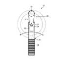
- FIG. 4is a diagram showing a force sense device according to the first embodiment of the present disclosure.
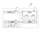
- FIG. 5is a block diagram showing a force sense device and a control device according to the first embodiment of the present disclosure.
- the force sense system 100includes a force sense device 10 operated by an operator and a control device 11 for controlling the force sense device 10.
- the force sense device 10 and the control device 11are connected so as to enable bidirectional communication.
- the force sense device 10 and the control device 11are connected so as to be capable of wired communication or wireless communication.
- the communication connection between the force sensor 10 and the control device 11may be made via the server.
- the force sense device 10is a device that presents a force sense regarding the behavior of the virtual object 1 to the operator.
- the force sense device 10is, for example, a device for use in a VR (Virtual Reality) game.
- the force sense device 10may be used in VR other than games, or may be used in AR (Augmented Reality).
- the force sense device 10has a rod-shaped member 21, a grip portion 22, a motion detection unit 23, and a force sense presentation unit 24.
- the rod-shaped member 21is a member formed in a rod shape along the longitudinal direction of the virtual object 1.
- the rod-shaped member 21may be formed in a cylindrical shape with the longitudinal direction as the axial direction, or may be formed in a prismatic shape. Further, the rod-shaped member 21 is not particularly limited to a rod-shaped member 21 formed linearly in the longitudinal direction, and if the rod-shaped member 21 is a rod-shaped member along the longitudinal direction, the rod-shaped member 21 may be partially curved, thick, or thin. There may be.
- the grip portion 22is a portion to be gripped by the operator, and is provided on one side of the rod-shaped member 21 in the longitudinal direction.
- the grip portion 22is, for example, subjected to anti-slip processing for suppressing slip when gripped by an operator.
- the non-slip processingis, for example, an annular groove processed along the circumference of the rod-shaped member 21 around the longitudinal direction, and a plurality of the grooves are arranged in the longitudinal direction.
- the motion detection unit 23detects the motion of the rod-shaped member 21 by the operator, and for example, an acceleration sensor such as a 3-axis acceleration sensor or a gyro sensor is applied.
- the motion detection unit 23may be any sensor as long as it detects the motion of the rod-shaped member 21.
- the motion detection unit 23is provided on the other side of the rod-shaped member 21 in the longitudinal direction, and is provided on the opposite side of the grip portion 22. Therefore, when the grip portion 22 side of the rod-shaped member 21 is set as the base end side, the motion detecting unit 23 is provided on the tip end side of the rod-shaped member 21, so that the motion detecting unit 23 appropriately detects the operation of the rod-shaped member 21. Will be done. Further, the motion detection unit 23 is connected to the control device 11 and outputs the detection result to the control device 11.
- the force sense presentation unit 24presents the force sense for reproducing the behavior of the virtual object 1 to the operator.
- the force sense presentation unit 24includes a support member 31, a weight 32, a connecting shaft 33, a motor (drive unit) 34, and a motor control unit 35.
- the support member 31is a member connected to the tip end side of the rod-shaped member 21 via a connecting shaft 33, and supports the weight 32.
- the support member 31is a member that is long in one direction, and an end portion on one side (base end side) is connected to the connecting shaft 33, and a weight 32 is provided on the end portion on the other side (tip end side). ..
- the support member 31is rotatable around the connecting shaft 33, and the weight 32 is rotatable around the connecting shaft 33.
- the weight 32is provided on the tip end side of the support member 31.
- the weight 32rotates around the connecting shaft 33 to present a sense of force to the operator who operates the rod-shaped member 21.
- the support member 31 and the weight 32may be treated as an integrated weight.
- the connecting shaft 33connects the rod-shaped member 21 and the support member 31, and rotatably supports the support member 31 with respect to the rod-shaped member 21.
- the axial direction of the connecting shaft 33is orthogonal to the longitudinal direction of the rod-shaped member 21. Therefore, the weight 32 can rotate in a two-dimensional orthogonal plane orthogonal to the connecting shaft 33.
- the support member 31 and the connecting shaft 33may be 1 or more. That is, a plurality of support members 31 may be connected and connected by a plurality of connecting shafts 33 to form a multi-axis configuration.
- the axial direction of the connecting shaft 33may be the same direction or different directions, and is not particularly limited. If the axial direction of the connecting shaft 33 is different, the weight 32 can rotate in the three-dimensional space.
- the motor 34is a drive source for rotating the support member 31 around the connecting shaft 33 with respect to the rod-shaped member 21, and by rotating the support member 31, the weight 32 is rotated via the support member 31. I'm moving it.
- a servo motoris applied as the motor 34.
- the motor 34is connected to the motor control unit 35 and is driven and controlled by the motor control unit 35.
- the motor control unit 35controls the motor 34 and is connected to the control device 11.
- the motor control unit 35drives and controls the motor 34 based on the control signal input from the control device 11.
- the motion detection unit 23 provided on the rod-shaped member 21detects and detects the motion of the rod-shaped member 21. The result is output to the control device 11.
- the motor control unit 35controls the motor 34 based on the control signal to reproduce the behavior of the virtual object 1.
- the senseis presented to the operator via the force sense presentation unit 24. As a result, as shown in FIG. 3, the support member 31 of the force sense presentation unit 24 appropriately rotates about the connecting shaft 33 with respect to the rod-shaped member 21.
- the control device 11generates a control signal of the force sense presentation unit 24 for reproducing the behavior of the virtual object 1 based on the detection result of the motion detection unit 23.
- the control device 11has a calculation unit 41 and a storage unit 42.
- the control device 11is, for example, a game device.
- the arithmetic unit 41is configured by using, for example, an integrated circuit such as a CPU (Central Processing Unit).
- the calculation unit 41calculates the behavior of the virtual object 1 based on the detection result of the motion detection unit 23 by executing the physics calculation engine.
- the storage unit 42stores programs and data. Further, the storage unit 42 may also be used as a work area for temporarily storing the processing result of the calculation unit 41.
- the storage unit 42includes, for example, a volatile memory such as RAM (Random Access Memory), a non-volatile memory such as ROM (Read Only Memory), a semiconductor storage device, and an arbitrary storage device such as a magnetic storage device. good. Further, the storage unit 42 may include a plurality of types of storage devices. Further, the storage unit 42 may include a combination of a portable storage medium such as a memory card and a reading device for the storage medium.
- the storage unit 42stores the physical quantity data D1 relating to the virtual object 1 and the data D2 relating to the detection result of the motion detecting unit 23 as data.
- the data D1includes information on the shape of the virtual object 1, the material of the virtual object 1, and the like as physical quantities related to the virtual object 1.
- the shape of the virtual object 1is the length of the virtual object 1 in the longitudinal direction and the like.
- the material of the virtual object 1is the elastic modulus of the material or the like.
- the data D1is data that has been input in advance and stored in the storage unit 42.
- the data D2is information on the time change of acceleration when the motion detection unit 23 is an acceleration sensor.
- the data D2is data acquired in real time from the motion detection unit 23.
- the calculation unit 41when the detection result of the motion detection unit 23 is input from the force sense device 10, the calculation unit 41 has the data D1 stored in the storage unit 42 and the detection result of the motion detection unit 23. And the data D2 which is.
- the calculation unit 41takes the data D1 and the data D2 as inputs, performs a physical calculation by the physics calculation engine, and acquires the time change of the acceleration as the behavior of the virtual object 1 to be reproduced.
- the calculation unit 41generates a signal related to the time change of the reproduced acceleration as a control signal, and outputs the control signal to the motor control unit 35 of the force sense device 10.
- FIG. 6is a graph showing the operation of the force sense device and the behavior of a virtual long object (virtual object 1).
- the horizontal axisis time and the vertical axis is amplitude.
- the line L1 in FIG. 6is a line relating to the time change of the amplitude of the movement of the rod-shaped member 21 in the force sense device 10.
- the line L2 in FIG. 6is a line relating to the time change of the amplitude of the operation of the virtual object 1 when the virtual object 1 is long.
- the line L3 in FIG. 6is a line relating to the time change of the amplitude of the operation of the virtual object 1 when the virtual object 1 is short.
- the line L1is a line obtained based on the detection result of the motion detection unit 23.
- the line L2 and the line L3are lines calculated by the physical calculation of the calculation unit 41 based on the line L1.
- the rod-shaped member 21 of the force sense device 10is from a position where the amplitude becomes zero to a position where the amplitude becomes a predetermined value in a plane orthogonal to the axial direction of the connecting shaft 33.
- the virtual object 1 long in the longitudinal directionvibrates on both sides in the amplitude direction around the longitudinal direction.
- the virtual object 1 short in the longitudinal directioncauses a bending that vibrates on both sides in the amplitude direction centering on the longitudinal direction.
- the virtual object 1 that is long in the longitudinal directionhas a larger amplitude, a longer period, and a longer time to converge than the virtual object 1 that is shorter in the longitudinal direction.
- the virtual object 1 short in the longitudinal directionhas a smaller amplitude, a shorter period, and a shorter time to converge than the virtual object 1 long in the longitudinal direction.
- FIG. 7is a flowchart relating to the control method of the force sensor according to the first embodiment of the present disclosure.
- the calculation unit 41 of the control device 11acquires the data D1 relating to the physical quantity of the virtual object 1 from the storage unit 42 (step S1). Subsequently, the calculation unit 41 acquires the operation of the force sense device 10, which is the detection result of the operation detection unit 23 (step S2). After that, the calculation unit 41 executes a physical calculation for reproducing the behavior of the virtual object 1 based on the data D1 and the data D2 (step S3). Then, the calculation unit 41 generates a control signal of the motor 34 based on the calculation result of the physical calculation, and outputs the generated control signal to the motor control unit 35 of the force sense presentation unit 24.
- the motor control unit 35When the motor control unit 35 acquires the control signal, the motor control unit 35 generates a control value for driving and controlling the motor 34 based on the control signal. That is, the motor control unit 35 converts the calculation result of the physical calculation into the control value of the motor 34 (step S4). After that, the motor control unit 35 executes the drive control of the motor 34 based on the control value (step S5). As described above, the force sense device 10 presents the force sense regarding the behavior of the virtual object 1 to the operator.
- the force sense presentation unit 24can present the force sense regarding the behavior of the virtual object 1 which is a virtual long object to the operator.
- the force sense presenting unit 24 using the weight 32is used to rotate the weight 32 around the connecting shaft 33, thereby appropriately presenting the force sense to the operator. be able to.
- the motion detection unit 23can be provided on the opposite side of the grip portion 22 of the rod-shaped member 21, the operation of the rod-shaped member 21 can be suitably detected.
- the acceleration sensoras the motion detection unit 23 the motion of the rod-shaped member 21 can be detected as an acceleration.
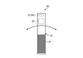
- FIG. 8is a diagram showing a force sense device according to the second embodiment of the present disclosure.
- the force sense device 50 of the second embodimenthas the oscillator 51 applied as the force sense presentation unit 24.
- the oscillator 51is a so-called force reactor.
- the oscillator 51is an element that vibrates in one direction (vibration direction), and presents a sense of force to one side in one direction or a sense of force to the other side in one direction depending on the mode of vibration. To do.
- the oscillator 51is provided on the tip end side of the rod-shaped member 21, and is provided so that the vibration direction is in the lateral direction orthogonal to the longitudinal direction of the rod-shaped member 21.
- the calculation unit 41 of the control device 11performs a physical calculation based on the data D1 and the data D2 to generate a control signal of the vibrator 51 regarding the behavior of the virtual object 1 to be reproduced.
- the oscillator 51presents a force sense regarding the behavior of the virtual object 1 to the operator by controlling the vibration based on the generated control signal.
- the force sense device 50can be made compact by applying the oscillator as the force sense presentation unit 24.
- FIG. 9is a diagram showing a force sensor according to the third embodiment of the present disclosure.
- the force sense device 60 of the third embodimentis further provided with a motion detection unit 61 on the proximal end side in the longitudinal direction of the rod-shaped member 21 in addition to the force sense device 10 of the first embodiment.
- the control device 11detects the operation of the rod-shaped member 21 based on the detection results of the operation detection unit 23 and the operation detection unit 61. Specifically, the control device 11 calculates a difference between the detection result of the motion detection unit 23 and the detection result of the motion detection unit 61, and detects this difference as the motion of the rod-shaped member 21. As a result, the control device 11 can acquire the relative displacement between the tip end side and the base end side of the rod-shaped member 21.
- the motion detection unit 23 and the motion detection unit 61can be provided on the tip end side and the proximal end side of the rod-shaped member 21, the operation of the rod-shaped member 21 can be performed accurately. Can be detected.
- the present inventionis not limited to the above embodiments.
- the components in the embodimentinclude those that can be easily replaced by those skilled in the art, or those that are substantially the same.
- the components described belowcan be appropriately combined, and when there are a plurality of embodiments, each embodiment can be combined.
- the force sense device 10 and the control device 11are separate bodies, but the force sense device 10 and the control device 11 may be integrated. That is, the force sense device 10 may be configured to include a control unit that functions as a control device 11.
- the present disclosuremay also have the following structure.
- a rod-shaped member formed along the longitudinal direction of a virtual long objectA grip portion provided on the rod-shaped member and gripped by the operator, An operation detection unit provided on the rod-shaped member and detecting the operation of the rod-shaped member, A force sense presentation unit provided on the rod-shaped member and presenting a force sense for reproducing the behavior of the long object to the operator based on the detection result of the motion detection unit.
- Force sense device equipped with(2)
- the force sense presentation unitis With weights A support member that connects the rod-shaped member and the weight via one or more connecting shafts, The force sense device according to (1), further comprising a drive unit that rotates the weight around the connecting shaft with respect to the rod-shaped member.
- the force sense devicewherein the force sense presentation unit is a vibrator that vibrates in the lateral direction orthogonal to the longitudinal direction.
- the grip portionis provided on one side of the rod-shaped member in the longitudinal direction.
- the force sensor according to (1), wherein the motion detecting unitis provided on the other side of the rod-shaped member in the longitudinal direction.
- the force sensor according to (1), wherein the motion detection unitis provided on both sides of the rod-shaped member in the longitudinal direction.
- the force detection deviceis an acceleration sensor.
- a control unit for controlling the force sense presentation unitis further provided. The control unit Obtain the physical quantity of the long object and obtain it.
- a control signal of the force sense presenting unit for reproducing the behavior of the long objectis generated.
- the force sense device according to (1) abovewhich controls the force sense presentation unit based on the generated control signal.
- a control device for a force sense device that controls the force sense device according to (1) aboveObtain the physical quantity of the long object and obtain it.
- Acquire the detection result of the motion detection unit, Based on the acquired physical quantity and the detection result, a control signal of the force sense presenting unit for reproducing the behavior of the long objectis generated.
Landscapes
- Engineering & Computer Science (AREA)
- Multimedia (AREA)
- Human Computer Interaction (AREA)
- General Engineering & Computer Science (AREA)
- Theoretical Computer Science (AREA)
- Physics & Mathematics (AREA)
- General Physics & Mathematics (AREA)
- User Interface Of Digital Computer (AREA)
Abstract
Description
Translated fromJapanese本開示は、力覚デバイス、力覚デバイスの制御装置及び力覚デバイスの制御方法に関する。The present disclosure relates to a force sense device, a force sense device control device, and a force sense device control method.
従来、ゲーム装置のコントローラを用いて、仮想空間のオブジェクトの動きをコントロールするゲーム装置が知られている(例えば、特許文献1参照)。特許文献1では、ゲーム装置が、コントローラの位置情報に基づいて算出される変位量がゼロとなるように補正している。これにより、ゲーム装置は、コントローラから取得されるコントローラの位置精度が低い場合であっても、仮想空間のオブジェクトに生じ得る手振れのような振動を抑制している。Conventionally, a game device that controls the movement of an object in a virtual space by using a controller of the game device is known (see, for example, Patent Document 1). In
ところで、コントローラ等の入力デバイスは、操作者に対して力覚を提示する力覚デバイスとして用いられる場合がある。しかしながら、力覚デバイスとして、仮想的な長尺の物体の挙動に関する力覚を操作者に提示する力覚デバイスは知られていない。仮想的な長尺の物体としては、例えば、剣、振り子等があり、挙動としては、例えば、剣のしなり、振り子の振動等である。By the way, an input device such as a controller may be used as a force sense device that presents a force sense to an operator. However, as a force sense device, there is no known force sense device that presents a force sense regarding the behavior of a virtual long object to an operator. Examples of the virtual long object include a sword, a pendulum, and the like, and examples of the behavior include bending of the sword, vibration of the pendulum, and the like.
そこで、本開示では、仮想的な長尺の物体の挙動に関する力覚を、操作者に提示することができる力覚デバイス、力覚デバイスの制御装置及び力覚デバイスの制御方法を提案する。Therefore, in the present disclosure, we propose a force sense device, a force sense device control device, and a force sense device control method capable of presenting a force sense regarding the behavior of a virtual long object to an operator.
上記の課題を解決するために、本開示に係る一形態の力覚デバイスは、仮想的な長尺の物体の長手方向に沿って形成される棒状部材と、前記棒状部材に設けられ、操作者が把持する把持部と、前記棒状部材に設けられ、前記棒状部材の動作を検出する動作検出部と、前記棒状部材に設けられ、前記動作検出部の検出結果に基づいて、前記操作者に対して前記長尺の物体の挙動を再現するための力覚を提示する力覚提示部と、を備える。In order to solve the above problems, the force sense device according to the present disclosure is provided with a rod-shaped member formed along the longitudinal direction of a virtual long object and the rod-shaped member provided with an operator. A gripping portion to be gripped by the rod-shaped member, an motion detecting unit provided on the rod-shaped member to detect the operation of the rod-shaped member, and a motion detecting unit provided on the rod-shaped member, based on the detection result of the motion detecting unit, to the operator. It is provided with a force sense presenting unit for presenting a force sense for reproducing the behavior of the long object.
また、本開示に係る一形態の力覚デバイスの制御装置は、上記の力覚デバイスを制御する力覚デバイスの制御装置であって、前記長尺の物体に関する物理量を取得し、前記動作検出部の検出結果を取得し、取得した前記物理量と前記検出結果とに基づいて、前記長尺の物体の挙動を再現するための前記力覚提示部の制御信号を生成し、生成した前記制御信号に基づいて、前記力覚提示部を制御する。Further, the control device for the force sense device according to the present disclosure is a control device for the force sense device that controls the force sense device, and acquires a physical quantity related to the long object, and the motion detection unit. The detection result of the above is acquired, and based on the acquired physical quantity and the detection result, a control signal of the force sense presenting unit for reproducing the behavior of the long object is generated, and the generated control signal is used. Based on this, the force sense presentation unit is controlled.
また、本開示に係る一形態の力覚デバイスの制御方法は、上記の力覚デバイスを制御する力覚デバイスの制御方法であって、前記長尺の物体に関する物理量を取得し、前記動作検出部の検出結果を取得し、取得した前記物理量と前記検出結果とに基づいて、前記長尺の物体の挙動を再現するための前記力覚提示部の制御信号を生成し、生成した前記制御信号に基づいて、前記力覚提示部を制御する。Further, the control method of the force sense device according to the present disclosure is the control method of the force sense device for controlling the force sense device, in which the physical quantity of the long object is acquired and the motion detection unit is used. The detection result of the above is acquired, and based on the acquired physical quantity and the detection result, a control signal of the force sense presenting unit for reproducing the behavior of the long object is generated, and the generated control signal is used. Based on this, the force sense presentation unit is controlled.
以下に、本開示の実施形態について図面に基づいて詳細に説明する。なお、以下の各実施形態において、同一の部位には同一の符号を付することにより重複する説明を省略する。Hereinafter, embodiments of the present disclosure will be described in detail with reference to the drawings. In each of the following embodiments, the same parts are designated by the same reference numerals, so that overlapping description will be omitted.
(第1実施形態)
本開示の第1実施形態に係る力覚デバイス10及び制御装置11は、力覚デバイス10を操作する操作者に対して、仮想的な長尺の物体(以下、仮想物体ともいう)1の挙動を再現するように力覚を提示する。力覚デバイス10及び制御装置11の説明に先立ち、仮想物体1について説明する。(First Embodiment)
The
(仮想的な長尺の物体)
図1及び図2は、本開示の仮想的な長尺の物体の一例を示す図である。図1に示す仮想物体1は、長手方向に長い剣3である。また、剣3は、長手方向の一方側の端部が把持部4となっている。仮想物体1が剣3である場合、再現される仮想物体1の挙動としては、例えば、剣3のしなりである。剣3のしなりとは、剣3の把持部4を支点とした弾性変化とも言える。図2に示す仮想物体1は、鉛直方向となる長手方向に延びた糸5と、糸5の下端部に固定された錘6からなる振り子7である。振り子7は、鉛直方向の上方側の糸5の端部が把持部8となっている。仮想物体1が振り子7である場合、再現される仮想物体1の挙動としては、例えば、振り子7の振動である。振り子7の振動とは、振り子7の把持部8を支点とする揺れとも言える。なお、仮想的な長尺の物体としては、剣3または振り子7に限られず、例えば、釣り竿、ゴルフクラブ等の棒状の物体であってもよい。また、仮想的な長尺の物体は、必ずしも棒状の物体でなくてもよい。例えば、仮想的な長尺の物体は、バトミントンのラケット等、一方の端部(把持部とは反対側の端部)に大きな膨らみを有する物体であってもよい。(Virtual long object)
1 and 2 are diagrams showing an example of a virtual long object of the present disclosure. The
上記した仮想物体1の挙動を、操作者に対する力覚として提示すべく、第1実施形態では、下記のような力覚デバイス10及び制御装置11を備える力覚システム100としている。In order to present the behavior of the
(力覚システム)
次に、図3から図5を参照して、力覚デバイス10と制御装置11とを備える力覚システム100について説明する。図3は、本開示の第1実施形態に係る力覚デバイスの操作に関する図である。図4は、本開示の第1実施形態に係る力覚デバイスを示す図である。図5は、本開示の第1実施形態に係る力覚デバイスと制御装置とを示すブロック図である。(Force sense system)
Next, the
力覚システム100は、図5に示すように、操作者によって操作される力覚デバイス10と、力覚デバイス10を制御する制御装置11とを備える。力覚デバイス10と制御装置11とは、双方向通信が可能となるように接続されている。力覚デバイス10と制御装置11とは、有線通信または無線通信が可能に接続されている。なお、力覚デバイス10と制御装置11との通信接続は、サーバを介して行われていてもよい。As shown in FIG. 5, the
(力覚デバイス)
力覚デバイス10は、図4に示すように、操作者に対して、仮想物体1の挙動に関する力覚を提示するデバイスなっている。力覚デバイス10は、例えば、VR(Virtual Reality)ゲームで使用するためのデバイスである。なお、力覚デバイス10は、ゲーム以外のVRで使用されてもよいし、AR(Augmented Reality)で使用されてもよい。力覚デバイス10は、棒状部材21と、把持部22と、動作検出部23と、力覚提示部24と、を有している。(Force sense device)
As shown in FIG. 4, the
棒状部材21は、仮想物体1の長手方向に沿って棒状に形成された部材である。棒状部材21は、長手方向を軸方向とする円柱形状に形成されていてもよいし、角柱形状に形成されていてもよい。また、棒状部材21は、長手方向に直線状に形成されたものに、特に限定されず、長手方向に沿う棒状のものであれば、一部が湾曲したり、太かったり、細かったりする形状であってもよい。The rod-
把持部22は、操作者が把持する部位となっており、棒状部材21の長手方向の一方側に設けられている。把持部22は、例えば、操作者が把持した際の滑りを抑制するための滑り止め加工が施されている。滑り止め加工としては、例えば、長手方向を中心として、棒状部材21の周囲に沿って加工された環状の溝であり、この溝を長手方向に複数並べた加工となっている。The
動作検出部23は、操作者による棒状部材21の動作を検出するものであり、例えば、3軸加速度センサーまたはジャイロセンサー等の加速度センサーが適用される。動作検出部23は、棒状部材21の動作を検出するものであれば、いずれのセンサーであってもよい。動作検出部23は、棒状部材21の長手方向の他方側に設けられており、把持部22の反対側に設けられている。このため、動作検出部23は、棒状部材21の把持部22側を基端側とすると、棒状部材21の先端側に設けられることから、動作検出部23により棒状部材21の動作が適切に検出される。また、動作検出部23は、制御装置11に接続されており、検出結果を制御装置11へ向けて出力している。The
力覚提示部24は、操作者に対して仮想物体1の挙動を再現するための力覚を提示するものである。力覚提示部24は、支持部材31と、重り32と、連結軸33と、モータ(駆動部)34と、モータ制御部35と、を有する。The force
支持部材31は、棒状部材21の先端側に、連結軸33を介して接続される部材であり、重り32を支持している。支持部材31は、一方向に長い部材となっており、一方側(基端側)の端部が連結軸33と連結され、他方側(先端側)の端部に重り32が設けられている。支持部材31は、連結軸33を中心に回動可能となっており、重り32が連結軸33を中心に周回可能となっている。The
重り32は、支持部材31の先端側に設けられている。重り32は、連結軸33を中心に回動することで、棒状部材21を操作する操作者に対して力覚を提示する。なお、支持部材31と重り32を、一体となる重りとして取り扱ってもよい。The
連結軸33は、棒状部材21と支持部材31とを連結すると共に、棒状部材21に対して支持部材31を回動自在に軸支している。連結軸33は、その軸方向が、棒状部材21の長手方向に直交する方向となっている。このため、重り32は、連結軸33に直交する2次元の直交面内において、回動可能となる。The connecting
ここで、支持部材31及び連結軸33は、1以上としてもよい。つまり、支持部材31を複数連ねて、複数の連結軸33により連結することで、多軸の構成としてもよい。この場合、連結軸33の軸方向は、同じ方向としてもよいし、異なる方向としてもよく、特に限定されない。連結軸33の軸方向を異なる方向にすれば、重り32は、3次元空間において回動可能となる。Here, the
モータ34は、棒状部材21に対して、連結軸33周りに支持部材31を回動させる駆動源となっており、支持部材31を回動させることで、支持部材31を介して重り32を回動させている。モータ34は、例えば、サーボモータが適用される。また、モータ34は、モータ制御部35に接続されており、モータ制御部35によって駆動制御される。The
モータ制御部35は、モータ34を制御しており、制御装置11に接続されている。モータ制御部35は、制御装置11から入力される制御信号に基づいて、モータ34を駆動制御する。The
上記のような力覚デバイス10において、操作者が把持部22を把持して棒状部材21を操作すると、棒状部材21に設けられた動作検出部23は、棒状部材21の動作を検出し、検出結果を制御装置11へ向けて出力する。一方で、制御装置11から力覚デバイス10へ制御信号が入力されると、モータ制御部35は、制御信号に基づいてモータ34を制御することにより、仮想物体1の挙動を再現するための力覚を、力覚提示部24を介して操作者に対して提示する。これにより、図3に示すように、力覚提示部24の支持部材31は、棒状部材21に対して、連結軸33を中心に適宜回動する。In the
(制御装置)
次に、図5を参照して、制御装置11について説明する。制御装置11は、動作検出部23の検出結果に基づいて、仮想物体1の挙動を再現するための力覚提示部24の制御信号を生成している。制御装置11は、演算部41と、記憶部42とを有する。制御装置11は、例えば、ゲーム装置である。(Control device)
Next, the control device 11 will be described with reference to FIG. The control device 11 generates a control signal of the force
演算部41は、例えば、CPU(Central Processing Unit)等の集積回路を用いて構成されている。演算部41は、物理演算エンジンを実行することで、動作検出部23の検出結果に基づく仮想物体1の挙動を演算する。The arithmetic unit 41 is configured by using, for example, an integrated circuit such as a CPU (Central Processing Unit). The calculation unit 41 calculates the behavior of the
記憶部42は、プログラム及びデータを記憶する。また、記憶部42は、演算部41の処理結果を一時的に記憶する作業領域としても利用してもよい。記憶部42は、例えば、RAM(Random Access Memory)等の揮発性メモリ、ROM(Read Only Memory)等の不揮発性メモリの他、半導体記憶デバイス、及び磁気記憶デバイス等の任意の記憶デバイスを含んでよい。また、記憶部42は、複数の種類の記憶デバイスを含んでもよい。また、記憶部42は、メモリカード等の可搬の記憶媒体と、記憶媒体の読み取り装置との組み合わせを含んでもよい。The storage unit 42 stores programs and data. Further, the storage unit 42 may also be used as a work area for temporarily storing the processing result of the calculation unit 41. The storage unit 42 includes, for example, a volatile memory such as RAM (Random Access Memory), a non-volatile memory such as ROM (Read Only Memory), a semiconductor storage device, and an arbitrary storage device such as a magnetic storage device. good. Further, the storage unit 42 may include a plurality of types of storage devices. Further, the storage unit 42 may include a combination of a portable storage medium such as a memory card and a reading device for the storage medium.
記憶部42は、データとして、仮想物体1に関する物理量のデータD1と、動作検出部23の検出結果に関するデータD2とを記憶する。データD1は、仮想物体1に関する物理量として、仮想物体1の形状、仮想物体1の材質等に関する情報を含む。仮想物体1の形状は、仮想物体1の長手方向における長さ等である。仮想物体1の材質は、材質の弾性係数等である。データD1は、予め入力され、記憶部42に記憶されたデータとなっている。データD2は、動作検出部23が加速度センサーである場合、加速度の時間変化に関する情報となっている。データD2は、動作検出部23からリアルタイムに取得されるデータとなっている。The storage unit 42 stores the physical quantity data D1 relating to the
上記のような制御装置11において、力覚デバイス10から動作検出部23の検出結果が入力されると、演算部41は、記憶部42に記憶されたデータD1と、動作検出部23の検出結果であるデータD2とを取得する。演算部41は、データD1及びデータD2を入力として、物理演算エンジンによる物理演算を行って、再現される仮想物体1の挙動としての、加速度の時間変化を取得する。演算部41は、再現される加速度の時間変化に関する信号を制御信号として生成し、制御信号を力覚デバイス10のモータ制御部35へ向けて出力する。In the control device 11 as described above, when the detection result of the
次に、図6を参照して、力覚デバイス10の動作と、再現される仮想物体1の挙動とについて説明する。図6は、力覚デバイスの動作と仮想的な長尺の物体(仮想物体1)の挙動を示すグラフである。図6は、その横軸が時間となっており、その縦軸が振幅となっている。Next, with reference to FIG. 6, the operation of the
図6のラインL1は、力覚デバイス10における棒状部材21の動作の振幅の時間変化に関するラインである。図6のラインL2は、仮想物体1が長い場合における仮想物体1の動作の振幅の時間変化に関するラインである。図6のラインL3は、仮想物体1が短い場合における仮想物体1の動作の振幅の時間変化に関するラインである。ラインL1は、動作検出部23の検出結果に基づいて得られるラインとなっている。ラインL2及びラインL3は、ラインL1に基づいて、演算部41の物理演算により算出されるラインとなっている。The line L1 in FIG. 6 is a line relating to the time change of the amplitude of the movement of the rod-shaped
図6のラインL1に示すように、力覚デバイス10の棒状部材21が、連結軸33の軸方向に直交する面内において、振幅がゼロとなる位置から、振幅が所定の値となる位置まで動作する。この場合、ラインL2において、長手方向に長い仮想物体1は、長手方向を中心に、振幅方向の両側に振動するしなりが発生する。同様に、ラインL3において、長手方向に短い仮想物体1は、長手方向を中心に、振幅方向の両側に振動するしなりが発生する。このとき、長手方向に長い仮想物体1は、長手方向に短い仮想物体1に比して振幅が大きく、周期が長く、収束までの時間が長いものとなっている。換言すれば、長手方向に短い仮想物体1は、長手方向に長い仮想物体1に比して振幅が小さく、周期が短く、収束までの時間が短いものとなっている。As shown in line L1 of FIG. 6, the rod-shaped
(力覚デバイスの制御方法)
次に、図7を参照して、力覚デバイスの制御方法について説明する。図7は、本開示の第1実施形態に係る力覚デバイスの制御方法に関するフローチャートである。(Control method of force sense device)
Next, a method of controlling the force sensation device will be described with reference to FIG. 7. FIG. 7 is a flowchart relating to the control method of the force sensor according to the first embodiment of the present disclosure.
力覚デバイス10の制御方法では、先ず、制御装置11の演算部41が、仮想物体1の物理量に関するデータD1を記憶部42から取得する(ステップS1)。続いて、演算部41は、動作検出部23の検出結果である力覚デバイス10の動作を取得する(ステップS2)。この後、演算部41は、データD1とデータD2とに基づいて、仮想物体1の挙動を再現するための物理演算を実行する(ステップS3)。そして、演算部41は、物理演算の演算結果に基づくモータ34の制御信号を生成し、生成した制御信号を力覚提示部24のモータ制御部35へ出力する。モータ制御部35は、制御信号を取得すると、制御信号に基づいて、モータ34を駆動制御するための制御値を生成する。つまり、モータ制御部35は、物理演算の演算結果をモータ34の制御値に変換する(ステップS4)。この後、モータ制御部35は、制御値に基づいて、モータ34の駆動制御を実行する(ステップS5)。以上により、力覚デバイス10は、操作者に対して仮想物体1の挙動に関する力覚を提示する。In the control method of the
以上のように、第1実施形態によれば、力覚提示部24により操作者に対して、仮想的な長尺の物体となる仮想物体1の挙動に関する力覚を提示することができる。As described above, according to the first embodiment, the force
また、第1実施形態では、重り32を用いた力覚提示部24とすることで、連結軸33を中心に重り32を回動させることにより、操作者に対して力覚を好適に提示することができる。Further, in the first embodiment, the force
また、第1実施形態では、動作検出部23を、棒状部材21の把持部22の反対側に設けることができるため、棒状部材21の動作を好適に検出することができる。Further, in the first embodiment, since the
また、第1実施形態では、動作検出部23として加速度センサーを適用することにより、棒状部材21の動作を、加速度として検出することができる。Further, in the first embodiment, by applying the acceleration sensor as the
(第2実施形態)
次に、図8を参照して、実施形態2に係る力覚デバイス50について説明する。なお、実施形態2では、重複した記載を避けるべく、実施形態1と異なる部分について説明し、実施形態1と同様の構成である部分については、同じ符号を付して説明する。図8は、本開示の第2実施形態に係る力覚デバイスを示す図である。(Second Embodiment)
Next, the
第2実施形態の力覚デバイス50は、力覚提示部24として、振動子51を適用したものとなっている。振動子51は、いわゆるフォースリアクターと呼称される振動子である。振動子51は、一方向(振動方向)に振動する素子となっており、振動する態様に応じて、一方向の一方側に力覚を提示したり、一方向の他方側に力覚を提示したりする。振動子51は、棒状部材21の先端側に設けられており、振動方向が棒状部材21の長手方向に直交する短手方向となるように設けられる。The
制御装置11の演算部41は、データD1及びデータD2に基づく物理演算を行って、再現される仮想物体1の挙動に関する振動子51の制御信号を生成する。振動子51は、生成された制御信号に基づいて振動が制御されることで、操作者に対して仮想物体1の挙動に関する力覚を提示する。The calculation unit 41 of the control device 11 performs a physical calculation based on the data D1 and the data D2 to generate a control signal of the
以上のように、第2実施形態では、力覚提示部24として振動子を適用することにより、力覚デバイス50をコンパクトにすることができる。As described above, in the second embodiment, the
(第3実施形態)
次に、図9を参照して、実施形態3に係る力覚デバイス60について説明する。なお、実施形態3では、重複した記載を避けるべく、実施形態1及び2と異なる部分について説明し、実施形態1及び2と同様の構成である部分については、同じ符号を付して説明する。図9は、本開示の第3実施形態に係る力覚デバイスを示す図である。(Third Embodiment)
Next, the
第3実施形態の力覚デバイス60は、第1実施形態の力覚デバイス10に加えて、棒状部材21の長手方向における基端側に動作検出部61をさらに備えたものとなっている。制御装置11は、動作検出部23及び動作検出部61の検出結果に基づいて、棒状部材21の動作を検出する。具体的に、制御装置11は、動作検出部23の検出結果と、動作検出部61の検出結果との差分を算出し、この差分を棒状部材21の動作として検出する。これにより、制御装置11は、棒状部材21の先端側と基端側との相対的な変位を取得することができる。The
以上のように、第3実施形態では、棒状部材21の先端側と基端側とのそれぞれに、動作検出部23及び動作検出部61を設けることができるため、棒状部材21の動作を精度良く検出することができる。As described above, in the third embodiment, since the
なお、以上の実施形態によりこの発明が限定されるものではない。また、実施形態における構成要素には、当業者が置換可能かつ容易なもの、あるいは実質的に同一のものが含まれる。さらに、以下に記載した構成要素は適宜組み合わせることが可能であり、また、実施形態が複数ある場合には、各実施形態を組み合わせることも可能である。The present invention is not limited to the above embodiments. In addition, the components in the embodiment include those that can be easily replaced by those skilled in the art, or those that are substantially the same. Further, the components described below can be appropriately combined, and when there are a plurality of embodiments, each embodiment can be combined.
また、第1実施形態から第3実施形態では、力覚デバイス10と制御装置11とが別体となっていたが、力覚デバイス10と制御装置11とが一体となっていてもよい。すなわち、力覚デバイス10が、制御装置11として機能する制御部を備える構成としてもよい。Further, in the first to third embodiments, the
以上のように、本開示は以下のような構成も取ることができる。
(1)
仮想的な長尺の物体の長手方向に沿って形成される棒状部材と、
前記棒状部材に設けられ、操作者が把持する把持部と、
前記棒状部材に設けられ、前記棒状部材の動作を検出する動作検出部と、
前記棒状部材に設けられ、前記動作検出部の検出結果に基づいて、前記操作者に対して前記長尺の物体の挙動を再現するための力覚を提示する力覚提示部と、
を備える力覚デバイス。
(2)
前記力覚提示部は、
重りと、
1以上の連結軸を介して前記棒状部材と前記重りとを連結する支持部材と、
前記棒状部材に対して前記連結軸周りに前記重りを回動させる駆動部と、を有する
前記(1)に記載の力覚デバイス。
(3)
前記力覚提示部は、前記長手方向に直交する短手方向に振動する振動子である
前記(1)に記載の力覚デバイス。
(4)
前記把持部は、前記棒状部材の前記長手方向における一方側に設けられ、
前記動作検出部は、前記棒状部材の前記長手方向における他方側に設けられる
前記(1)に記載の力覚デバイス。
(5)
前記動作検出部は、前記棒状部材の前記長手方向の両側に設けられる
前記(1)に記載の力覚デバイス。
(6)
前記動作検出部は、加速度センサーである
前記(1)に記載の力覚デバイス。
(7)
前記力覚提示部を制御する制御部を、さらに備え、
前記制御部は、
前記長尺の物体に関する物理量を取得し、
前記動作検出部の検出結果を取得し、
取得した前記物理量と前記検出結果とに基づいて、前記長尺の物体の挙動を再現するための前記力覚提示部の制御信号を生成し、
生成した前記制御信号に基づいて、前記力覚提示部を制御する
前記(1)に記載の力覚デバイス。
(8)
前記(1)に記載の力覚デバイスを制御する力覚デバイスの制御装置であって、
前記長尺の物体に関する物理量を取得し、
前記動作検出部の検出結果を取得し、
取得した前記物理量と前記検出結果とに基づいて、前記長尺の物体の挙動を再現するための前記力覚提示部の制御信号を生成し、
生成した前記制御信号に基づいて、前記力覚提示部を制御する
力覚デバイスの制御装置。
(9)
前記(1)に記載の力覚デバイスを制御する力覚デバイスの制御方法であって、
前記長尺の物体に関する物理量を取得し、
前記動作検出部の検出結果を取得し、
取得した前記物理量と前記検出結果とに基づいて、前記長尺の物体の挙動を再現するための前記力覚提示部の制御信号を生成し、
生成した前記制御信号に基づいて、前記力覚提示部を制御する
力覚デバイスの制御方法。As described above, the present disclosure may also have the following structure.
(1)
A rod-shaped member formed along the longitudinal direction of a virtual long object,
A grip portion provided on the rod-shaped member and gripped by the operator,
An operation detection unit provided on the rod-shaped member and detecting the operation of the rod-shaped member,
A force sense presentation unit provided on the rod-shaped member and presenting a force sense for reproducing the behavior of the long object to the operator based on the detection result of the motion detection unit.
Force sense device equipped with.
(2)
The force sense presentation unit is
With weights
A support member that connects the rod-shaped member and the weight via one or more connecting shafts,
The force sense device according to (1), further comprising a drive unit that rotates the weight around the connecting shaft with respect to the rod-shaped member.
(3)
The force sense device according to (1), wherein the force sense presentation unit is a vibrator that vibrates in the lateral direction orthogonal to the longitudinal direction.
(4)
The grip portion is provided on one side of the rod-shaped member in the longitudinal direction.
The force sensor according to (1), wherein the motion detecting unit is provided on the other side of the rod-shaped member in the longitudinal direction.
(5)
The force sensor according to (1), wherein the motion detection unit is provided on both sides of the rod-shaped member in the longitudinal direction.
(6)
The force detection device according to (1) above, wherein the motion detection unit is an acceleration sensor.
(7)
A control unit for controlling the force sense presentation unit is further provided.
The control unit
Obtain the physical quantity of the long object and obtain it.
Acquire the detection result of the motion detection unit,
Based on the acquired physical quantity and the detection result, a control signal of the force sense presenting unit for reproducing the behavior of the long object is generated.
The force sense device according to (1) above, which controls the force sense presentation unit based on the generated control signal.
(8)
A control device for a force sense device that controls the force sense device according to (1) above.
Obtain the physical quantity of the long object and obtain it.
Acquire the detection result of the motion detection unit,
Based on the acquired physical quantity and the detection result, a control signal of the force sense presenting unit for reproducing the behavior of the long object is generated.
A control device for a force sense device that controls the force sense presentation unit based on the generated control signal.
(9)
The method for controlling a force sense device according to (1) above, wherein the force sense device is controlled.
Obtain the physical quantity of the long object and obtain it.
Acquire the detection result of the motion detection unit,
Based on the acquired physical quantity and the detection result, a control signal of the force sense presenting unit for reproducing the behavior of the long object is generated.
A method for controlling a force sense device that controls the force sense presentation unit based on the generated control signal.
1 仮想物体
10 力覚デバイス
11 制御装置
21 棒状部材
22 把持部
23 動作検出部
24 力覚提示部
31 支持部材
32 重り
33 連結軸
34 モータ
35 モータ制御部
41 演算部
42 記憶部1
Claims (9)
Translated fromJapanese前記棒状部材に設けられ、操作者が把持する把持部と、
前記棒状部材に設けられ、前記棒状部材の動作を検出する動作検出部と、
前記棒状部材に設けられ、前記動作検出部の検出結果に基づいて、前記操作者に対して前記長尺の物体の挙動を再現するための力覚を提示する力覚提示部と、
を備える力覚デバイス。A rod-shaped member formed along the longitudinal direction of a virtual long object,
A grip portion provided on the rod-shaped member and gripped by the operator,
An operation detection unit provided on the rod-shaped member and detecting the operation of the rod-shaped member,
A force sense presentation unit provided on the rod-shaped member and presenting a force sense for reproducing the behavior of the long object to the operator based on the detection result of the motion detection unit.
Force sense device equipped with.
重りと、
1以上の連結軸を介して前記棒状部材と前記重りとを連結する支持部材と、
前記棒状部材に対して前記連結軸周りに前記重りを回動させる駆動部と、を有する
請求項1に記載の力覚デバイス。The force sense presentation unit is
With weights
A support member that connects the rod-shaped member and the weight via one or more connecting shafts,
The force sensor according to claim 1, further comprising a drive unit that rotates the weight around the connecting shaft with respect to the rod-shaped member.
請求項1に記載の力覚デバイス。The force sense device according to claim 1, wherein the force sense presentation unit is a vibrator that vibrates in the lateral direction orthogonal to the longitudinal direction.
前記動作検出部は、前記棒状部材の前記長手方向における他方側に設けられる
請求項1に記載の力覚デバイス。The grip portion is provided on one side of the rod-shaped member in the longitudinal direction.
The force sensor according to claim 1, wherein the motion detecting unit is provided on the other side of the rod-shaped member in the longitudinal direction.
請求項1に記載の力覚デバイス。The force sensor according to claim 1, wherein the motion detection unit is provided on both sides of the rod-shaped member in the longitudinal direction.
請求項1に記載の力覚デバイス。The force sensor according to claim 1, wherein the motion detection unit is an acceleration sensor.
前記制御部は、
前記長尺の物体に関する物理量を取得し、
前記動作検出部の検出結果を取得し、
取得した前記物理量と前記検出結果とに基づいて、前記長尺の物体の挙動を再現するための前記力覚提示部の制御信号を生成し、
生成した前記制御信号に基づいて、前記力覚提示部を制御する
請求項1に記載の力覚デバイス。A control unit for controlling the force sense presentation unit is further provided.
The control unit
Obtain the physical quantity of the long object and obtain it.
Acquire the detection result of the motion detection unit,
Based on the acquired physical quantity and the detection result, a control signal of the force sense presenting unit for reproducing the behavior of the long object is generated.
The force sense device according to claim 1, wherein the force sense presentation unit is controlled based on the generated control signal.
前記長尺の物体に関する物理量を取得し、
前記動作検出部の検出結果を取得し、
取得した前記物理量と前記検出結果とに基づいて、前記長尺の物体の挙動を再現するための前記力覚提示部の制御信号を生成し、
生成した前記制御信号に基づいて、前記力覚提示部を制御する
力覚デバイスの制御装置。A control device for a force sense device that controls the force sense device according to claim 1.
Obtain the physical quantity of the long object and obtain it.
Acquire the detection result of the motion detection unit,
Based on the acquired physical quantity and the detection result, a control signal of the force sense presenting unit for reproducing the behavior of the long object is generated.
A control device for a force sense device that controls the force sense presentation unit based on the generated control signal.
前記長尺の物体に関する物理量を取得し、
前記動作検出部の検出結果を取得し、
取得した前記物理量と前記検出結果とに基づいて、前記長尺の物体の挙動を再現するための前記力覚提示部の制御信号を生成し、
生成した前記制御信号に基づいて、前記力覚提示部を制御する
力覚デバイスの制御方法。The method for controlling a force sense device according to claim 1, wherein the force sense device is controlled.
Obtain the physical quantity of the long object and obtain it.
Acquire the detection result of the motion detection unit,
Based on the acquired physical quantity and the detection result, a control signal of the force sense presenting unit for reproducing the behavior of the long object is generated.
A method for controlling a force sense device that controls the force sense presentation unit based on the generated control signal.
Applications Claiming Priority (2)
| Application Number | Priority Date | Filing Date | Title |
|---|---|---|---|
| JP2020-183813 | 2020-11-02 | ||
| JP2020183813 | 2020-11-02 |
Publications (1)
| Publication Number | Publication Date |
|---|---|
| WO2022091911A1true WO2022091911A1 (en) | 2022-05-05 |
Family
ID=81382394
Family Applications (1)
| Application Number | Title | Priority Date | Filing Date |
|---|---|---|---|
| PCT/JP2021/038770CeasedWO2022091911A1 (en) | 2020-11-02 | 2021-10-20 | Force sense device, control device of force sense device, and control method of force sense device |
Country Status (1)
| Country | Link |
|---|---|
| WO (1) | WO2022091911A1 (en) |
Citations (5)
| Publication number | Priority date | Publication date | Assignee | Title |
|---|---|---|---|---|
| JPH10214155A (en)* | 1997-01-30 | 1998-08-11 | Sega Enterp Ltd | INPUT DEVICE, GAME PROCESSING DEVICE, ITS METHOD, AND RECORDING MEDIUM |
| JP2000308756A (en)* | 1999-04-27 | 2000-11-07 | Taito Corp | Input controller of game device |
| JP2003180896A (en)* | 2001-12-17 | 2003-07-02 | Kazuyoshi Tsukamoto | Virtual sport system |
| JP2010225155A (en)* | 2009-03-24 | 2010-10-07 | Immersion Corp | Handheld computer interface with haptic feedback |
| JP2018126340A (en)* | 2017-02-08 | 2018-08-16 | 株式会社バンダイナムコエンターテインメント | Simulation system, program and controller |
- 2021
- 2021-10-20WOPCT/JP2021/038770patent/WO2022091911A1/ennot_activeCeased
Patent Citations (5)
| Publication number | Priority date | Publication date | Assignee | Title |
|---|---|---|---|---|
| JPH10214155A (en)* | 1997-01-30 | 1998-08-11 | Sega Enterp Ltd | INPUT DEVICE, GAME PROCESSING DEVICE, ITS METHOD, AND RECORDING MEDIUM |
| JP2000308756A (en)* | 1999-04-27 | 2000-11-07 | Taito Corp | Input controller of game device |
| JP2003180896A (en)* | 2001-12-17 | 2003-07-02 | Kazuyoshi Tsukamoto | Virtual sport system |
| JP2010225155A (en)* | 2009-03-24 | 2010-10-07 | Immersion Corp | Handheld computer interface with haptic feedback |
| JP2018126340A (en)* | 2017-02-08 | 2018-08-16 | 株式会社バンダイナムコエンターテインメント | Simulation system, program and controller |
Similar Documents
| Publication | Publication Date | Title |
|---|---|---|
| JP6390076B2 (en) | Motion analysis apparatus, motion analysis program, and notification method | |
| JP6007636B2 (en) | Robot control system and robot control apparatus | |
| WO2021149563A1 (en) | Robot simulation device | |
| EP4246271A1 (en) | Method and apparatus for controlling motion state, and device and readable storage medium | |
| US11880528B2 (en) | Stimulus transmission device | |
| US20100022300A1 (en) | Device with spatially unrestricted force feedback | |
| US20240019935A1 (en) | Haptic device, control device for haptic device, and control method for haptic device | |
| JP6413290B2 (en) | Golf club determination method, golf club determination device, and golf club determination program | |
| WO2022091911A1 (en) | Force sense device, control device of force sense device, and control method of force sense device | |
| US20240025039A1 (en) | Learning physical features from tactile robotic exploration | |
| JP6903137B2 (en) | Vibration control device | |
| JP5978768B2 (en) | Measuring system | |
| US9536319B2 (en) | Motion analysis method, motion analysis display method, and motion analysis device | |
| JP2008012222A (en) | Swing simulation method and design method of golf club | |
| JP6029097B2 (en) | Golf swing analysis apparatus and golf swing analysis method | |
| JPH08173632A (en) | Tv game machine | |
| JP2005228322A (en) | Vibration control method and apparatus using acceleration sensor, and robot joint drive system. | |
| JP6560823B2 (en) | Robot, control method therefor, and control program | |
| JP2017148913A (en) | ROBOT, CONTROL DEVICE, AND ROBOT CONTROL METHOD | |
| JP2004242907A (en) | Golf swing simulation method and golf swing evaluation method | |
| JP5897893B2 (en) | Input device for game machine, game machine | |
| JP2006201089A (en) | Model characteristics generation method | |
| JP6076873B2 (en) | robot | |
| TW202418047A (en) | Operating device | |
| JP2023073828A (en) | Workpiece takeout device, workpiece takeout method, program, and control device |
Legal Events
| Date | Code | Title | Description |
|---|---|---|---|
| 121 | Ep: the epo has been informed by wipo that ep was designated in this application | Ref document number:21886030 Country of ref document:EP Kind code of ref document:A1 | |
| NENP | Non-entry into the national phase | Ref country code:DE | |
| 122 | Ep: pct application non-entry in european phase | Ref document number:21886030 Country of ref document:EP Kind code of ref document:A1 | |
| NENP | Non-entry into the national phase | Ref country code:JP |