WO2022088109A1 - Attaching device - Google Patents
Attaching deviceDownload PDFInfo
- Publication number
- WO2022088109A1 WO2022088109A1PCT/CN2020/125579CN2020125579WWO2022088109A1WO 2022088109 A1WO2022088109 A1WO 2022088109A1CN 2020125579 WCN2020125579 WCN 2020125579WWO 2022088109 A1WO2022088109 A1WO 2022088109A1
- Authority
- WO
- WIPO (PCT)
- Prior art keywords
- module
- peeling
- cylinder
- workpiece
- reclaiming
- Prior art date
- Legal status (The legal status is an assumption and is not a legal conclusion. Google has not performed a legal analysis and makes no representation as to the accuracy of the status listed.)
- Ceased
Links
Images


Classifications
- B—PERFORMING OPERATIONS; TRANSPORTING
- B32—LAYERED PRODUCTS
- B32B—LAYERED PRODUCTS, i.e. PRODUCTS BUILT-UP OF STRATA OF FLAT OR NON-FLAT, e.g. CELLULAR OR HONEYCOMB, FORM
- B32B37/00—Methods or apparatus for laminating, e.g. by curing or by ultrasonic bonding
- B32B37/0046—Methods or apparatus for laminating, e.g. by curing or by ultrasonic bonding characterised by constructional aspects of the apparatus
- B32B37/0053—Constructional details of laminating machines comprising rollers; Constructional features of the rollers
- B—PERFORMING OPERATIONS; TRANSPORTING
- B32—LAYERED PRODUCTS
- B32B—LAYERED PRODUCTS, i.e. PRODUCTS BUILT-UP OF STRATA OF FLAT OR NON-FLAT, e.g. CELLULAR OR HONEYCOMB, FORM
- B32B38/00—Ancillary operations in connection with laminating processes
- B32B38/10—Removing layers, or parts of layers, mechanically or chemically
Definitions
- the present applicationrelates to a laminating device, and more particularly, to a laminating device that can automatically tear off the film and attach the parts to be attached.
- the workpiecewhen the workpiece is attached to the part to be attached, such as a graphite sheet, it is necessary to tear off the release paper on the adhesive surface of the graphite sheet, then attach the graphite sheet to the workpiece, and finally tear off the protection on the non-adhesive surface of the graphite sheet. membrane.
- the traditional operation methodis to manually perform actions such as tearing off the film and attaching it, which has the problems of low efficiency and low accuracy.
- An embodiment of the present applicationprovides a laminating device, which includes a bottom plate, a feeding module, a reclaiming module, a driving module, a first peeling module, a second peeling module, a carrier module, and a conveying line mold Group, the bottom plate is used for carrying.
- the feeding moduleis used for storing the parts to be bonded.
- the reclaiming moduleis used for adsorbing the to-be-bonded parts.
- the first peeling moduleis used for clamping and peeling the first film layer of the to-be-bonded part.
- the second peeling moduleis fixed on the reclaiming module for clamping and peeling the second film layer of the to-be-bonded part.
- the carrier moduleis used for positioning the workpiece.
- the conveying line moduleis arranged above the carrier module, and the conveying line module is used for conveying the workpiece to the carrier module.
- the feeding module, the first stripping module, the driving module, the carrier module and the conveying line moduleare arranged on the bottom plate.
- the driving moduleis used to drive the reclaiming module to adsorb the to-be-bonded part and move it to the first peeling module, which is used to clamp the part to be bonded.
- the first film layer, the driving modulecooperates with the first peeling module to peel off the first film layer; the driving module is used to further drive the reclaiming module to move to any position on the carrier module.
- the second peeling moduleis used to clamp the second film layer of the to-be-bonded part, and the drive The module cooperates with the second peeling module to peel off the second film layer.
- the laminating devicefurther includes a rolling module, the rolling module is arranged between the reclaiming module and the second peeling module, the rolling The module is used for pressing the part to be bonded onto the workpiece; the rolling module includes a roller and a lift cylinder, and the roller is used to press the part to be bonded under the drive of the lift cylinder pressed onto the workpiece.
- the first peeling moduleis fixedly connected to the bottom plate, and includes a clamping jaw cylinder, a first clamping jaw and a second clamping jaw, the first clamping jaw and the second clamping jaw
- the clawis used to clamp the first film layer
- the clamping claw cylinderis fixedly connected to the bottom plate
- the clamping claw cylinderis used to drive the first clamping claw and the second clamping claw to move closer or apart to clamp Hold or release the first film layer.
- the first peeling moduleis rotatably connected to the bottom plate, and includes a clamping jaw cylinder, a first clamping jaw, a second clamping jaw, a square cylinder, a circular arc slide rail, and a connecting piece.
- connecting rod and bearingone end of the connecting piece is fixedly connected to the square cylinder, the other end is connected to one end of the connecting rod, the other end of the connecting rod is connected to the bearing, and the bearing is installed on the circular cylinder
- the clamping claw cylinderis connected to the connecting rod, and the square cylinder is used to drive the connecting piece to move, so that the connecting piece drives the connecting rod to rotate, thereby driving the clamping claw cylinder, the first The jaw and the second jaw rotate together.
- a first communication hole and a second communication holeare opened on the bottom plate, and the first communication hole is used to collect the first film layer torn off by the first peeling module,
- the second communication holeis located on one side of the first peeling module and is close to the conveying line module, and the second communication hole is used for collecting the second peeling off the second peeling module. film layer.
- the first communication hole and the second communication holecommunicate with a collection box at the same time, and the first film layer and the second peeling off the first peeling module The second film layer torn off by the module all falls into the collection box.
- the reclaiming moduleincludes a fixing plate, a suction plate, an elastic member and a guide member, the fixing plate is installed on the driving module, and the suction plate is placed on the below the fixing plate; one end of the guide piece is installed on the suction plate, and the other end is slidably passed through the fixing plate; the two ends of the elastic piece are respectively connected to the fixing plate and the suction plate, and are elastically downward pushes the adsorption plate; the adsorption plate is provided with a plurality of adsorption holes for adsorbing the to-be-bonded parts.
- the second peeling moduleincludes a carrier, a suction member, a propelling cylinder, a linkage mechanism and a pressing member
- the carrieris installed on the driving module, and the suction
- the suction member and the propulsion cylinderare arranged on the carrier;
- the suction memberis provided with suction holes, and the suction holes are used to absorb the second film layer;
- the pressing memberis connected to the A pushing cylinder is used for driving the pressing member to press the adsorption member, so that the adsorption member and the pressing member clamp the second film layer.
- the linkage mechanismincludes a guide rod, a push block and a connecting rod
- the guide rodis mounted on the carrier
- the push blockis slidably connected to the guide rod
- the push rodis slidably connected to the guide rod.
- the blockis provided with a sliding part
- the pressing partis provided with a receiving groove
- the sliding partis slidably placed in the receiving groove
- the pressing partis connected to the bearing part through a connecting rod
- the propulsion cylinderdrives the After the push block moves along the guide rod, the sliding portion is used to drive the pressing member to swing, so as to be pressed against or away from the adsorption member.
- the carrier moduleincludes a base plate, at least two first centering blocks, at least two second centering blocks, an air cylinder, a first guide rail, a second guide rail and a linkage mechanism
- the base plateis used to carry the workpiece, the first guide rail and the second guide rail are respectively arranged along the first direction and the second direction; the first centering block and the second centering block pass through the
- the first guide rail and the second guide railare slidably arranged on the base plate, and are respectively used to clamp the to-be-bonded part;
- the air cylinderis installed on the base plate, and is driven by the link mechanism.
- the first centering block and the second centering blockare respectively approached or separated at the same time to clamp or loosen the to-be-fitted piece.
- the link mechanismincludes a slider, a first link, a second link and a guide post, the slider is connected to the cylinder and passes through the guide post, so The guide post is arranged along the first direction to guide the slider; the first link is rotatably mounted on the base plate, and two ends are respectively connected to the slider and the first link on one side.
- a pair of centering blocks, the first centering block on the other sideis fixedly connected to the sliding block, the two ends of the second connecting rod are respectively connected to the sliding block and one of the second centering blocks, the sliding block is along the The movement in the first direction drives the first centering block and the second centering block on opposite sides to approach to clamp the to-be-bonded piece.
- the conveying line moduleincludes two parallel belts, a top support guide wheel, a bottom support guide wheel, a side support guide wheel and a belt lifting motor, and the belt is used for conveying the workpiece , the bottom support guide wheel, the side support guide wheel and the bottom support guide wheel are used to support the belt, and the belt lift motor is connected to the top support guide wheel to lift or drop the top support Support the guide pulley to lift or lower the belt.
- An embodiment of the present applicationprovides a laminating device, which includes a feeding module, a reclaiming module, a driving module, a first peeling module, a second peeling module, a carrier module, and a conveying line module.
- the feeding moduleis used for storing the parts to be laminated including the upper film and the lower film.
- the reclaiming moduleis used for adsorbing and pressing the parts to be bonded.
- the driving moduleThe reclaiming module is arranged on the driving module, and the driving module is used for driving the reclaiming module to move along the first direction and the second direction.
- the carrier moduleis used for positioning the workpiece.
- the conveying line moduleis arranged above the carrier module, the conveying line module is arranged along the third direction, and the conveying line module is used for conveying the workpiece to the carrier mold along the third direction on the group.
- the driving moduleis used to drive the reclaiming module to move along the first direction to the feeding module to absorb the to-be-bonded part, and move to the first peeling module.
- the first peeling module and the driving modulecooperate to complete the operation of tearing off the film on the part to be bonded, and the driving module further drives the reclaiming module along the second direction to press the part to be bonded on the part to be bonded.
- the driving module and the second peeling modulecooperate to complete the operation of tearing off the film from the piece to be adhered.
- the laminating devicefurther includes a rolling module, the rolling module is arranged between the reclaiming module and the second peeling module, the rolling The module is used for pressing the part to be bonded onto the workpiece; the rolling module includes a roller and a lift cylinder, and the roller is used to press the part to be bonded under the drive of the lift cylinder pressed onto the workpiece.
- the first peeling moduleincludes a gripper cylinder, a first gripper and a second gripper, and the first gripper and the second gripper are used for gripping the
- the clamping jaw cylinderis used to drive the first clamping jaw and the second clamping jaw to approach or move away to clamp or loosen the upper film.
- the first peeling moduleincludes a clamping jaw cylinder, a first clamping jaw, a second clamping jaw, a square cylinder, a circular arc slide rail, a connecting piece, a connecting rod and a bearing.
- One end of the pieceis fixedly connected to the square cylinder, the other end is connected to one end of the connecting rod, the other end of the connecting rod is connected to the bearing, the bearing is installed in the arc slide rail, and the clamping jaw
- the cylinderis connected to the connecting rod, and the square cylinder is used to drive the connecting piece to move, so that the connecting piece drives the connecting rod to rotate, and then drives the clamping claw cylinder, the first clamping claw and the second clamping claw to rotate together.
- the second peeling moduleincludes a carrier, a suction member, a propelling cylinder, a linkage mechanism and a pressing member
- the carrieris installed on the driving module, and the suction
- the push-piece and the pusher cylinderare arranged on the carrier; the suction piece is used to absorb the lower film; the pressing piece is connected to the pusher cylinder through the linkage mechanism, and the pusher cylinder is used to drive the The pressing member presses the suction member to clamp the lower film.
- the laminating devicefurther includes a bottom plate for carrying the feeding module, the first peeling module, the driving module, the carrier module and the In the conveying line module, the bottom plate is provided with a first communication hole and a second communication hole, and the second communication hole is located on one side of the first stripping module and is close to the conveying line module, The first communication hole and the second communication hole communicate with a collection box at the same time, and the collection box is used for collecting the upper film and the lower film torn off by the first peeling module and the second peeling module.
- the above-mentioned laminating devicefirst takes the material from the feeding module through the reclaiming module, then peels off the first film layer through the first peeling module, and then drives the reclaiming module through the driving module to attach the to-be-laminated part to the Finally, the second peeling module is driven by the driving module to tear off the second film layer on the surface of the workpiece, so as to realize the purpose of automatically bonding the workpiece to be bonded to the workpiece, and improve the processing efficiency and accuracy.
- FIG. 1is a three-dimensional schematic diagram of a laminating device according to an embodiment of the present application.
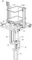
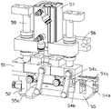
- FIG. 2is a three-dimensional schematic diagram of a reclaiming module, a rolling module and a second peeling module in FIG. 1 .
- FIG. 3is a three-dimensional schematic diagram of a feeding module in an embodiment of the present application.
- FIG. 4is a schematic perspective view of a reclaiming module according to an embodiment of the application.
- FIG. 5is a perspective view of the bottom of the reclaiming module in FIG. 4 .
- FIG. 6is a three-dimensional schematic diagram of the first peeling module and the bottom plate according to an embodiment of the present application.
- FIG. 7is a schematic perspective view of the first peeling module in FIG. 6 .
- FIG. 8is an exploded view of the first peeling module in FIG. 7 .
- FIG. 9is a schematic perspective view of a first peeling module in another embodiment of the present application.
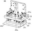
- FIG. 10is a schematic perspective view of a second peeling module in an embodiment of the present application.
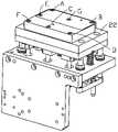
- FIG. 11is a perspective view of another state of the second peeling module in FIG. 10 .
- FIG. 12is a three-dimensional schematic diagram of a rolling module in an embodiment of the application.
- FIG. 13is a side view of the rolling module, the reclaiming module and the second peeling module in FIG. 1 .
- FIG. 14is a side view of the rolling module, the reclaiming module and the second peeling module in another state in FIG. 13 .
- FIG. 15is a side view of another state of the rolling module, the reclaiming module and the second peeling module in FIG. 14 .
- FIG. 16is a schematic perspective view of a carrier module according to an embodiment of the application.
- FIG. 17is a perspective view of the bottom of the carrier module in FIG. 16 .
- 18Ais a side view of the conveyor line module lifting the workpiece from the carrier module.
- 18Bis a side view of the conveyor line module dropping workpieces onto the carrier module.
- FIG. 19is a side view of a conveyor line module in an embodiment of the application.
- FIG. 20is a three-dimensional schematic diagram of a conveying line module according to an embodiment of the present application.
- An embodiment of the present applicationprovides a laminating device, which includes a bottom plate, a feeding module, a reclaiming module, a driving module, a first peeling module, a second peeling module, a carrier module, and a conveying line mold Group, the bottom plate is used for carrying.
- the feeding moduleis used for storing the parts to be bonded.
- the reclaiming moduleis used for adsorbing the to-be-bonded parts.
- the first peeling moduleis used for clamping and peeling the first film layer of the to-be-bonded part.
- the second peeling moduleis fixed on the reclaiming module for clamping and peeling the second film layer of the to-be-bonded part.
- the carrier moduleis used for positioning the workpiece.
- the conveying line moduleis arranged above the carrier module, and the conveying line module is used for conveying the workpiece to the carrier module.
- the feeding module, the first stripping module, the driving module, the carrier module and the conveying line moduleare arranged on the bottom plate.
- the driving moduleis used to drive the reclaiming module to adsorb the to-be-bonded part and move it to the first peeling module, which is used to clamp the part to be bonded.
- the first film layer, the driving modulecooperates with the first peeling module to peel off the first film layer; the driving module is used to further drive the reclaiming module to move to any position on the carrier module.
- the second peeling moduleis used to clamp the second film layer of the to-be-bonded part, and the drive The module cooperates with the second peeling module to peel off the second film layer.
- An embodiment of the present applicationalso provides a laminating device, including a feeding module, a reclaiming module, a driving module, a first peeling module, a second peeling module, a carrier module and a conveying line module .
- the feeding moduleis used for storing the parts to be laminated including the upper film and the lower film.
- the reclaiming moduleis used for adsorbing and pressing the parts to be bonded.
- the driving moduleThe reclaiming module is arranged on the driving module, and the driving module is used for driving the reclaiming module to move along the first direction and the second direction.
- the carrier moduleis used for positioning the workpiece.
- the conveying line moduleis arranged above the carrier module, the conveying line module is arranged along the third direction, and the conveying line module is used for conveying the workpiece to the carrier mold along the third direction on the group.
- the driving moduleis used to drive the reclaiming module to move along the first direction to the feeding module to absorb the to-be-bonded part, and move to the first peeling module.
- the first peeling module and the driving modulecooperate to complete the operation of tearing off the film on the part to be bonded, and the driving module further drives the reclaiming module along the second direction to press the part to be bonded on the part to be bonded.
- the driving module and the second peeling modulecooperate to complete the operation of tearing off the film from the piece to be adhered.
- the above-mentioned laminating devicefirst takes the material from the feeding module through the reclaiming module, then peels off the first film layer through the first peeling module, and then drives the reclaiming module through the driving module to attach the to-be-laminated part to the Finally, the second peeling module is driven by the driving module to tear off the second film layer on the surface of the workpiece, so as to realize the purpose of automatically bonding the workpiece to be bonded to the workpiece, and improve the processing efficiency and accuracy.
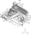
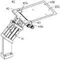
- FIG. 1is a schematic perspective view of a laminating device 100 according to an embodiment of the present application.
- the bonding device 100is used for bonding the to-be-bonded piece 200 to the workpiece.
- the laminating device 100includes a base plate 100a and a feeding module 10, a reclaiming module 20, a driving module 30, a first stripping module 40, a second stripping module 50, and a rolling module 60 disposed on the base plate 100a , a carrier module 70 and a conveyor line module 80 .
- the feeding module 10is used for storing a plurality of pieces 200 to be bonded.
- the to-be-applied member 200includes a first film layer and a second film layer respectively disposed on opposite sides.
- the first film layer of the piece to be bonded 200is a lower film with release paper attached to its adhesive surface
- the second film layer of the piece to be bonded 200is a lower film with a release paper on its adhesive surface.
- the area of the release paperis larger than the area of the piece to be attached 200 .
- the reclaiming module 20 , the second peeling module 50 and the rolling module 60are fixed on the driving module 30 together.
- the driving module 30is used to drive the reclaiming module 20 together with the second peeling module 50 and the rolling module 60 to move to the feeding module 10 to allow the reclaiming module 20 to reclaim the material, and the driving module 30 further
- the reclaiming module 20 carrying the piece to be bonded 200is driven to move to the first peeling module 40, so that the first peeling module 40 peels off the release paper on the piece 200 to be bonded, exposing the part 200 to be bonded.
- the driving module 30then drives the reclaiming module 20 carrying the piece to be bonded 200 with the peeled paper back to the top of the conveying line module 80 .
- the conveying line module 80carries a plurality of workpieces in real time. When one of the workpieces moves above the carrier module 70, the conveying line module 80 moves down, and the workpiece falls to the carrier module 70 and is automatically positioned to wait to be pasted. 200 pieces.
- the driving module 30then drives the reclaiming module 20 to move down to fit the piece to be bonded 200 on the workpiece. After bonding, the driving module 30 drives the reclaiming module 20 , the rolling module 60 and the second peeling module 50 to rise to a predetermined position together. The rolling module 60 is further moved downward relative to the reclaiming module 20 to press and fit the workpiece with the fitting member 200 .
- the rolling module 60is reset, and the second peeling module 50 can move downward relative to the rolling module 60 to further peel off the protective film on the non-adhesive surface of the bonding member 200 .
- the conveyor line module 80lifts the pasted workpiece to leave the carrier module 70 , and the conveyor line module 80 further drives the pasted workpiece to move to the next station.
- the driving module 30further drives the reclaiming module 20 to move to the next reclaiming position, and repeating the above steps, the laminating device 100 realizes the processes of automatic reclaiming, tearing off the film, laminating, pressing and tearing off the film.
- FIG. 3is a schematic perspective view of the feeding module 10 in FIG. 1 .
- the feeding module 10is mounted on the bottom plate 100 a, and includes a base 10 a and a lifting mechanism 11 .
- the base 10ais fixed to the bottom plate 100a.
- two positioning holesare preset on the piece to be bonded 200
- two positioning rods 10bare provided on the base 10a
- the relative position of the positioning rod 10bis the same as that of the two positioning holes on the piece to be bonded 200 .
- the positions of the positioning rods 10bcorrespond to the positioning holes, so as to allow the positioning rods 10b to be inserted into the positioning holes to guide the movement of the to-be-applied member 200 .
- the to-be-bonded member 200is a graphite sheet with a sheet-like shape, and is pierced on the positioning rod 10b in the form of stacking multiple sheets.
- the lifting mechanism 11is used to lift the lower to-be-bonded member 200 to move the lower to-be-bonded member 200 to the upper side when the reclaiming module 20 sequentially takes away the to-be-bonded member 200 above the feeding module 10 .
- the lifting mechanism 11should lift the next to-be-bonded piece 200 in time.
- the gap between the positioning rod 10b and the positioning holeis between 0 and 0.03 mm to ensure the feeding accuracy.
- the lifting mechanism 11includes a lifting rail 12 , a lifting seat 13 , a motor 14 , a screw 15 , a guide rod 16 , a fixing member 17 and a moving seat 18 .
- the lift rail 12is placed at the bottom of the base 10a.
- the lift seat 13is slidably placed on the lift rail 12 and can be lifted and lowered in a vertical direction.
- the motor 14is placed at the bottom of the lift base 13 and connected to the screw 15 .
- the fixing member 17is fixedly installed on the base 10a.
- the top of the screw 15is threaded through the fixing member 17 .
- the two guide rods 16are placed on both sides of the screw rod 15 respectively, and pass through the base 10a slidably.
- the moving base 18is placed above the base 10 a and is connected to the top of the guide rod 16 .
- the moving base 18is used to carry the stacked pieces to be bonded 200 .
- the motor 14can drive the screw rod 15 to rotate in the forward or reverse direction, so that the screw rod 15 rises or falls under the action of the fixing member 17 , drives the lift base 13 to rise or fall along the lift rail 12 , and then drives the movable base 18 to rise or fall.
- the moving base 18rises to move the lower parts 200 to be attached to the upper part, so that the reclaiming module 20 can take out the lower parts 200 to be attached. .
- the base 10a of the feeding module 10is further provided with a through-beam fiber optic sensor (not shown), which is placed on both sides of the to-be-bonded member 200 for sensing the to-be-bonded member 200 .
- the position of the component 200is ensured to ensure that the reclaiming module 20 reclaims the material stably and accurately.
- a material-free alarm(not shown) is added at the bottom of the base 10a to give an alarm after the use of the to-be-bonded part 200 is completed, reminding to replenish the to-be-bonded part 200 .
- the reclaiming module 20is fixed on the driving module 30 together with the second peeling module 50 and the rolling module 60 .
- the reclaiming module 20moves to the feeding module 10 together with the second peeling module 50 and the rolling module 60 to allow the reclaiming module 20 to reclaim the material.
- the reclaiming module 20includes a fixing plate 21 , an adsorption plate 22 , a plurality of elastic members 23 and a plurality of guide members 24 .
- the fixing plate 21is installed on the driving module 30 and is used for fixing the reclaiming module 20 to the driving module 30 .
- the adsorption plate 22is placed under the fixing plate 21 for adsorbing the to-be-bonded piece 200 .
- the guide member 24is mounted on the adsorption plate 22 , and the other end is slidably passed through the fixing plate 21 for guiding the movement of the adsorption plate 22 .
- the elastic member 23is placed between the fixing plate 21 and the suction plate 22, and the two ends are respectively connected to the fixing plate 21 and the suction plate 22, and elastically pushes the suction plate 22 downward to press the to-be-bonded member 200 to the workpiece.
- the adsorption plate 22is provided with a plurality of adsorption holes, and each adsorption hole is connected to a negative pressure member through a plurality of pipelines 22a, and the negative pressure member is used to generate a vacuum negative pressure to adsorb the to-be-bonded member 200 .
- the reclaiming module 20includes four guide members 24 and two elastic members 23 .
- a connecting plate 24 ais connected between one end of each two guide members 24 passing through the fixing plate 21 .
- the stopper 25is fixedly mounted on the connecting plate 24a for limiting the upward movement of the suction plate 22 .
- the distance between the positioning rod 10b (as shown in FIG. 3 ) and the positioning holewill be very close, resulting in the friction between the to-be-fitted part 200 and the positioning rod 10b during reclaiming.
- the number and position of more than 22 adsorption holesare arranged according to the needs to strengthen the local suction and improve the success rate of material reclaiming.
- the bottom of the adsorption plate 22is provided with seven adsorption holes.
- the first suction hole Ais located at the position where the liner is to be peeled off, and the torque here is relatively large when the liner is peeled off, which is used to prevent the material from falling out when the liner is peeled off.
- the second adsorption hole Bis used for sucking the rear area of the piece to be bonded, and plays an auxiliary role in stabilization.
- the third adsorption hole Cis located around a positioning rod 10b. Since there is a large frictional force in this area, the third adsorption hole C can reduce the material reclaiming force arm and increase the success rate of material reclaiming.
- the fourth adsorption hole Dis used to absorb the area of the piece to be attached at the rear, and plays an auxiliary role in stabilization.
- the fifth adsorption hole Eis close to the position of tearing off the liner to prevent material drop.
- the sixth adsorption hole Fis in balance with the third adsorption hole C to achieve the best reclaiming state.
- the seventh adsorption hole Gis located around the other positioning rod 10b. Due to the large frictional force in this area, the seventh adsorption hole G can reduce the material reclaiming force arm and increase the success rate of material reclaiming.
- the adsorption plate 22may also be provided with other adsorption holes in different numbers and positions.
- the first peeling module 40is installed on the bottom plate 100 a of the laminating device 100 and is located at one side of the feeding module 10 .
- the upper surface of the bottom plate 100ais provided with a shielding wall 40a
- the lower surface of the bottom plate 100ais provided with a collection box 40b
- the bottom plate 100ais provided with a first communication hole 100b
- the first communication hole 100bcommunicates with the shielding wall 40a and the collection box The cavity formed by 40b.
- the first peeling module 40is used to tear off the release paper of the to-be-bonded part 200 above the blocking wall 40a. After the first peeling module 40 releases the release paper, the release paper falls freely to the blocking wall 40a by gravity. inside the first communication hole 100b.
- the blocking wall 40ais used to ensure that the release paper enters the collection box 40b through the first communication hole 100b when the release paper is dropped.
- the collection box 40bis used to collect a plurality of dropped release papers so as to recycle the release papers.
- the bottom plate 100aalso has a second communication hole 100c.
- the second communication hole 100cis located on one side of the first stripping module 40 and is set close to the conveying line module 80.
- the second communication hole 100calso communicates with the collection box 40b.
- the driving module 30drives the second peeling module 50 together with the protective film to move above the second communication hole 100c, and the second peeling module 50 is released After the protective film is removed, the protective film falls into the collection box 40b through the second communication hole 100c by gravity, so as to recover the protective film.
- the first stripping module 40is fixed on the bottom plate 100a.
- the first peeling module 40includes a clamping jaw cylinder 41 , a first clamping jaw 42 and a second clamping jaw 43 .
- the area of the release paper 400needs to be larger than the area of the part to be attached 200 , so the first clamping jaw 42 and the second clamping jaw 43 can clamp the part of the release paper 400 extending out of the part to be attached 200 .
- the clamping positionis located at the front end of the release paper 400 in the moving direction of the piece to be bonded 200 , so that the release paper 400 gradually separates from the piece to be bonded 200 when the reclaiming module 20 drives the piece to be bonded 200 forward.
- the clamping jaw cylinder 41is fixed on the bottom plate 100a, and is used to drive the first clamping jaw 42 and the second clamping jaw 43 to approach or move away, so as to clamp or release the release paper 400.
- a slope 42ais provided on the side of the first clamping claw 42 facing the piece to be bonded 200 .
- the inclined surface 42ais used to form a space for avoiding space on the side facing the piece to be bonded 200 , so that the reclaiming module 20 can drive the piece to be bonded 200 to move forward and upward, thereby peeling off the release paper 400 .
- the side of the second jaw 43 holding the release paper 400is provided with a plurality of suction holes 43a, the suction holes 43a are communicated inside the second jaw 43, and pass through the interface 43b on the side of the second jaw 43 A vacuum negative pressure device is connected, and the vacuum negative pressure device absorbs the release paper 400 through the suction hole 43 a to prevent the release paper 400 from separating from the first clamping jaw 42 and the second clamping jaw 43 .
- the first peeling module 40is rotatably connected to the bottom plate 100 a to assist in tearing off the release paper 400 , so as to improve the efficiency of tearing off the release paper 400 .
- the first peeling module 40includes a square cylinder 44, a circular arc slide rail 45, The connecting piece 46 , the connecting rod 47 and the two bearings 48 .
- the arc slide rail 45is fixed on the bottom plate 100a, the arc slide rail 45 is provided with an arc groove 45a, and the arc of the arc groove 45a is 90 degrees.
- the square cylinder 44is installed on the bottom of the arc slide rail 45 .
- One end of the connecting piece 46is fixedly connected to the square cylinder 44 , and the other end is rotatably connected to the upper end of the connecting rod 47 . Both ends of the connecting rod 47 are rotatably connected to the bearings 48, and the two bearings 48 are respectively slidably and rotatably installed in the arc grooves 45a. At the same time, the bottom of the clamping jaw cylinder 41 is fixedly mounted on the connecting rod 47 .
- the two ends of the connecting rod 47are placed in the arc groove 45a through the bearing 48, so the linear movement of the connecting member 46 will be converted into the counterclockwise rotation and the diagonal downward movement of the connecting rod 47, so that the release paper 400 can be more efficient detached from the piece to be bonded 200 .
- the arc of the circular arc groove 45amay also be at other angles, such as 120 degrees.
- the driving module 30includes a slide rail 31 , a slide rail motor 33 and a lifter 32 .
- the slide rail 31is horizontally arranged and perpendicular to the conveying direction of the conveying line module 80 .
- the lifter 32is slidably mounted on the slide rail 31 , and the slide rail motor 33 is used to drive the lifter 32 to reciprocate along the slide rail 31 along the X-axis to approach or move away from the conveyor line module 80 .
- the conveying line module 80conveys the workpiece along the Y-axis direction, and the reclaiming module 20 is installed on the lifter 32 .
- the lifter 32is used to drive the reclaiming module 20 to lift up and down along the Z axis to suck or fit the pieces to be bonded.
- one end of the slide rail 31is close to the conveying line module 80 and is placed above the conveying line module 80 .
- the feeding module 10is located at one end of the slide rail 31 away from the conveying line module 80, and the first stripping module 40 is located between the feeding module 10 and the conveying line module 80, so that the reclaiming module 20 can be separated from the feeding module. 10 After obtaining the parts to be bonded, move to the first peeling module 40 to peel off the release paper 400 , and then move to the conveying line module 80 to bond the parts to be bonded 200 .
- FIG. 10is a schematic perspective view of the second peeling module 50 according to an embodiment of the present application.
- the second peeling module 50includes a bearing member 51 , an adsorption member 52 , a propelling cylinder 53 , a linkage mechanism 54 , a pressing member 55 , a connecting member 56 , a lifting cylinder 57 and a sliding column 58 .
- the carrier 51is connected to the driving module 30 .
- the suction member 52 and the propelling cylinder 53are arranged on the carrier member 51 .
- the bottom of the adsorption member 52is provided with an adsorption hole (not shown), and the adsorption hole communicates with a negative pressure member for adsorbing the part of the protective film 500 extending out of the to-be-bonded member 200 .
- the pressing piece 55is connected to the propulsion cylinder 53 through the linkage mechanism 54 .
- the pushing cylinder 53is used to drive the pressing member 55 to press the bottom of the adsorption member 52 , so that the adsorption member 52 and the pressing member 55 clamp the protective film 500 , and then the protective film 500 can be peeled off.
- the connecting piece 56is mounted on the rolling module 60 by screws, so as to fix the second peeling module 50 to the rolling module 60, and then connect the reclaiming module 20, so that the second peeling module 50 can follow the reclaiming module. Group 20 moves.
- the sliding column 58is mounted on the bearing member 51 and passes through the connecting member 56 to guide the bearing member 51 .
- the lifting cylinder 57is installed on the connecting member 56 and is used to drive the bearing member 51 to lift and lower, so as to absorb or lift the protective film 500 .
- the portion of the protective film 500 extending from the to-be-bonded member 200is a rectangular surface
- a pressing piece 55 ais provided at one end of the pressing member 55 close to the adsorption member 52 , and the adsorption member 52 absorbs the rectangular surface of the protective film 500 , the lifting cylinder 57 lifts it a certain distance, so that the pressing piece 55 can drive the pressing piece 55a to move to the bottom of the rectangular surface and press the rectangular surface upward to prevent the rectangular surface from falling off during the peeling process of the protective film 500 .
- FIG. 10shows the state in which the pressing member 55 is away from the adsorption member 52
- FIG. 11is the state in which the pressing member 55 is close to the adsorption member 52
- the linkage mechanism 54includes a guide rod 54a, a push block 54b and four connecting rods 54c.
- the guide rod 54ais horizontally arranged and mounted on the carrier 51 .
- the push block 54bis slidably connected to the guide rod 54a and can slide along the guide rod 54a.
- the push block 54bis provided with a sliding portion 54d, and the sliding portion 54d is a roller to reduce friction.
- An end of the pressing member 55 close to the guide rod 54ais provided with a receiving groove 55b, and the receiving groove 55b is arranged vertically.
- the sliding portion 54dis slidably placed in the accommodating groove 55b for pushing against the groove wall of the accommodating groove 55b to drive the pressing member 55 to move.
- the pressing member 55is connected to the bearing member 51 through four connecting rods 54c, and each two connecting rods are placed on opposite sides of the pressing member 55 and are arranged parallel to each other to form a parallelogram structure.
- the sliding portion 54dcan push against the groove wall of the receiving groove 55b, thereby driving the pressing member 55 to swing, so as to be pressed against or away from the adsorption member 52, and then clamped or released.
- Protective film 500.
- the rolling module 60includes a roller 61 , a moving block 62 , a fixing block 63 , an elastic member 64 , a lifting cylinder 65 , a straight rod 66 and a mounting plate 67 .
- the mounting plate 67is fixedly mounted on the fixing plate 21 , so that the rolling module 60 is fixedly connected to the reclaiming module 20 to move with the reclaiming module 20 .
- the lift cylinder 65is mounted on the top of the mounting plate 67 , and the bottom is connected to the fixing block 63 through the mounting plate 67 .
- the bottom of the straight rod 66is fixedly connected to the fixed block 63 , and the top passes through the mounting plate 67 for guiding the movement of the fixed block 63 .
- Both ends of the drum 61are installed at the bottom of the moving block 62 .
- the roller 61is used for pressing the part to be bonded onto the workpiece under the driving of the lift cylinder 65 , and the driving module 30 drives the rolling module 60 to reciprocate to drive the roller 61 to press the part to be bonded 200 .
- the lifting cylinder 65 of the rolling module 60drives the fixed block 63 to move downward, so that the roller 61 is lower than the level of the adsorption part 22 until the roller 61 is pressed down to be attached
- the slide motor 33 of the driving module 30drives the reclaiming module 20 to move back and forth, and then drives the rolling module 60 to move back and forth to press the to-be-bonded member 200 .
- the lift cylinder 57 of the second peeling module 50drives the carrier 51 to move downward, so that the suction member 52 is lower than the horizontal height of the suction member 22 for suction
- the protective filmis then lifted by the lifting cylinder 57 to lift the adsorption member 52 by a certain distance, so that the pressing member 55 can drive the pressing piece 55a to move to the bottom of the protective film and press the protective film upward.
- the driving module 30drives the reclaiming module 20 together with the second peeling module 50 moves toward the second communication hole 100c to drive the second peeling module 50 to peel off the protective film, and is collected in the collection box 40b.
- the carrier module 70is disposed below the conveying line module 80 , which is used for positioning the workpiece 300 to be bonded.
- the carrier module 70includes a base plate 70 a , at least two first centering blocks 71 , at least two second centering blocks 72 , an air cylinder 73 , a first guide rail 74 , a second guide rail 75 and a link mechanism 76 .
- the base plate 70 ais used to carry the workpiece 300 .
- the first guide rail 74 and the second guide rail 75are respectively disposed along a first direction and a second direction, and the second direction is perpendicular to the first direction.
- the first centering block 71 and the second centering block 72are slidably arranged on the base plate 70a through the first guide rail 74 and the second guide rail 75 respectively, and are used for symmetrical clamping along the first direction and the second direction respectively.
- the air cylinder 73is installed on the base plate 70a, and can drive the link mechanism 76 to drive the first centering block 71 and the second centering block 72 to approach or move away from each other at the same time to clamp or loosen the workpiece 300, and to make the workpiece 300 symmetrical Positioned on two centerlines that are perpendicular to the substrate 70a.
- the link mechanism 76includes a slider 76a, a first link 76b, a second link 76c and a guide post 76d.
- the sliding block 76ais connected to the cylinder 73 and passes through the guide post 76d.
- the guide post 76dis provided along the first direction for guiding the slider 76a.
- Each first link 76bis rotatably mounted on the base plate 70a at a position between the two ends, and the two ends are respectively connected to the slider 76a and the first centering block 71 on one side and the first centering block on the other side. 71 is fixedly connected to the slider 76a and moves with the slider 76a.
- each second link 76cBoth ends of each second link 76c are respectively connected to the slider 76a and a second centering block 72, so that the slider 76a can drive the first centering blocks 71 and the second centering blocks on both sides after moving in the first direction.
- the blocks 72are close together to clamp the workpiece 300 .
- first centering blocks 71on both sides of the workpiece and are symmetrically arranged.
- the second centering blocks 72are provided on both sides of the workpiece and are symmetrically arranged.
- the two first centering blocks 71 on one sideare connected to the bottom of the slider 76a through a connecting plate 71a.
- the base plate 70ais provided with a suction cup 70b, and the suction cup 70b is used for suctioning the workpiece after centering the workpiece, so as to prevent the workpiece from being lifted.
- the carrier module 70is disposed below the conveying line module 80 , which is used for positioning the workpiece 300 to be bonded.
- the conveying line module 80includes two parallel belts 81 on which the workpieces are placed, and the belts 81 move to convey the workpieces 300 .
- the carrier module 70is placed under the belt 81 , and the belt 81 can ascend or descend relative to the carrier module 70 .
- the belt 81descends, and the workpiece 300 falls onto the carrier module 70, so that the carrier module 70 positions the workpiece 300; after the workpiece 300 is attached, the belt 81 rises , the workpiece 300 is far away from the carrier module 70, so that the belt 81 continues to convey the workpiece.
- the conveying line module 80further includes two sets of top support guide wheels 82, two sets of bottom support guide wheels 83, two sets of side support guide wheels 84 and two Belt lift motor 85.
- the belt 81is used for conveying the workpiece.
- Each set of bottom support guide wheels 83is installed on the bottom plate 100a of the laminating device 100 , and is used to support and guide the bottom of a belt 81
- each set of side support guide wheels 84is used to support and guide both ends of a belt 81 , respectively.
- each set of top support guide wheels 82is used to support and guide the top of a belt 81 respectively.
- the belt lift motor 85is arranged on the bottom plate 100a, and is connected to each corresponding set of top support guide wheels 82 respectively.
- the belt lift motor 85is used to lift or drop the top support guide wheel 82 to lift or drop the belt 81, thereby lifting or lowering the belt 81. Lower the workpiece.
- the belt lift motor 85lifts the workpiece, and when the workpiece moves above the carrier module 70, the belt lift motor 85 drops the belt 81 so that the workpiece falls onto the carrier module 70, thereby making the carrier Tool module 70 aligns the workpiece.
- the belt lift motor 85lifts the workpieces through the top support guide wheel 82, so that the conveying line module 80 continues to transport the attached workpieces to the next station.
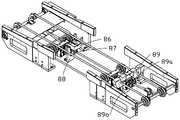
- the conveying line module 80further includes a first blocking block 86 , a first blocking cylinder 87 , a first bracket 88 , a second blocking block 89 , a first blocking block 89 , a The second stopper cylinder 89a and the second bracket 89b.
- the first bracket 88is installed on the bottom plate 100 a
- the first material blocking cylinder 87is installed on the first bracket 88
- the first material blocking block 86is connected to the first material blocking cylinder 87 .
- the first stopper cylinder 87is used to drive the first stopper block 86 to rise or fall.
- the second bracket 89bis mounted on the bottom plate 100a, the second stopper cylinder 89a is mounted on the second bracket 89b, and the second stopper block 89 is connected to the second stopper cylinder 89a.
- the second stopper cylinder 89ais used to drive the second stopper block 89 to rise or fall.
- the laminating process of the laminating device 100is as follows: the slide rail motor 33 drives the reclaiming module 20, the second peeling module 50 and the rolling module 60 to move along the slide rail 31 to the top of the feeding module 10, and the motor 14 drives the screw 15 rotates, the screw 15 drives the lifting seat 13 to rise along the lifting rail 12, and then drives the moving seat 18 to rise, and then moves the lower part to be bonded 200 to the upper; the lifter 32 drives the adsorption plate 22 to descend, as shown in Figure 13 As shown, the rolling module 60 and the second peeling module 50 are higher than the suction plate 22; the suction plate 22 absorbs the parts to be bonded 200 through a plurality of suction holes; after the parts to be bonded 200 are adsorbed, the lifter 32 drives the reclaiming die The group 20, the rolling module 60 and the second peeling module 50 rise together, the slide rail motor 33 drives the reclaiming module 20 to move along the slide rail 31 to the top of the first stripping module 40; the gripper cylinder 41 drives the first clip The claw
- the liner 400gradually falls off the to-be-bonded part 20.
- the gripper cylinder 41drives the first gripper 42 and the second gripper 43 away from each other to release the release liner 400, and the release liner 400 automatically falls to the collection.
- the slide rail motor 33drives the reclaiming module 20 to move along the slide rail 31 to the top of the carrier module 70, the belt lift motor 85 drops the workpiece, and at the same time the cylinder 73 of the carrier module 70 drives the first centering block 71 and the second centering block 72 respectively clamp the workpiece at the same time, and position the workpiece symmetrically on two vertical centerlines of the base plate 70a; Attached to the workpiece; the adsorption plate 22 of the reclaiming module 20 stops adsorbing, and the lifter 32 drives the reclaiming module 20, the rolling module 60 and the second peeling module 50 to rise together; after the reclaiming module 20 rises , the lifting cylinder 65 drives the fixed block 63 to move downward, so that the drum 61 is lower than the horizontal height of the adsorption member 22, as shown in FIG.
- the sliding rail motor 33 of the driving module 30drives the reclaiming module 20 to move once or reciprocates, and then drives the rolling module 60 to move back and forth to press the to-be-bonded part 200 on the workpiece; after rolling, the lifting cylinder 65
- the fixing block 63is driven to rise and reset; the lifting cylinder 57 of the second peeling module 50 drives the bearing member 51 to move downward until the bearing member 51 is lower than the rolling module 60 and the reclaiming module 20 as shown in FIG.
- the part of the protective film 500 extending beyond the part to be bonded 200is placed under the adsorption part 52; while the adsorption part 52 adsorbs the protective film 500, the pushing cylinder 53 drives the push block 54b to move backward along the guide rod 54a, and the sliding part 54d pushes against it.
- the groove wall of the receiving groove 55bdrives it to move backward, and the pressing member 55 swings under the restraint of the connecting rod 54c until the pressing member 52 is pressed against the suction member 52, and then the protective film 500 is clamped;
- the slide rail motor 33drives the reclaiming module 20 to After moving backward, the protective film 500 is driven to gradually separate from the piece to be bonded 200;
- the slide rail motor 33drives the second peeling module 50 together with the protective film 500 to move to the top of the shielding wall 40a, and then the pushing cylinder 53 drives the push block 54b to move along the guide rod 54a.
- the belt lift motor 85lifts the workpiece again, so that the conveying line module 80 continues to transport the workpiece; finally, the sliding rail motor 33 drives the reclaiming module 20 to move along the sliding rail 31 to the top of the feeding module 10 again. , and repeat the above steps to attach a new piece 200 to be attached.
- An embodiment of the present applicationfurther provides a film sticking operation line (not shown), and the film sticking operation line includes the above-mentioned laminating device 100 .
- the driving module 30can also be driven in one direction, such as the same direction as the conveying line module 80 , so as to drive the rolling module 60 to press the parts to be bonded.
- the above-mentioned laminating device 100first takes the material from the feeding module 10 through the reclaiming module 20, then tears off the release paper through the first peeling module 40, and then drives the reclaiming module 20 through the driving module 30 to remove the material to be pasted.
- the fittingis attached to the surface of the workpiece, and finally, the second peeling module 50 is driven by the driving module 30 to tear off the protective film, which realizes the purpose of automatically attaching the to-be-attached piece to the workpiece, and improves the processing efficiency and accuracy.
Landscapes
- Engineering & Computer Science (AREA)
- Mechanical Engineering (AREA)
- Sheets, Magazines, And Separation Thereof (AREA)
- Feeding Of Articles By Means Other Than Belts Or Rollers (AREA)
- Laminated Bodies (AREA)
Abstract
Description
Translated fromChinese本申请涉及一种贴合装置,尤其涉及一种可实现将待贴合件自动撕膜、贴合等操作的贴合装置。The present application relates to a laminating device, and more particularly, to a laminating device that can automatically tear off the film and attach the parts to be attached.
目前在工件贴合待贴合件如石墨片时,需要先撕下石墨片有胶面上的离型纸,再将石墨片贴合至工件上,最后撕下石墨片无胶面上的保护膜。在组装过程中,传统作业方式为人工进行撕膜、贴合等动作,存在效率低下、精准度低的问题。At present, when the workpiece is attached to the part to be attached, such as a graphite sheet, it is necessary to tear off the release paper on the adhesive surface of the graphite sheet, then attach the graphite sheet to the workpiece, and finally tear off the protection on the non-adhesive surface of the graphite sheet. membrane. In the assembly process, the traditional operation method is to manually perform actions such as tearing off the film and attaching it, which has the problems of low efficiency and low accuracy.
发明内容SUMMARY OF THE INVENTION
有鉴于此,有必要提供一种能够自动撕膜、贴合待贴合件至工件上的贴合装置。In view of this, it is necessary to provide a bonding device capable of automatically tearing off the film and bonding the to-be-bonded piece to the workpiece.
本申请一实施例中提供一种贴合装置,包括底板、供料模组、取料模组、驱动模组、第一剥离模组、第二剥离模组、载具模组及输送线模组,底板用于承载。所述供料模组用于存放待贴合件。取料模组用于吸附所述待贴合件。所述第一剥离模组用于夹持和剥离所述待贴合件的第一膜层。第二剥离模组固定在所述取料模组上,用于夹持和剥离所述待贴合件的第二膜层。所述载具模组用于定位工件。输送线模组设置在所述载具模组上方,所述输送线模组用于输送所述工件至所述载具模组上。所述供料模组、所述第一剥离模组,所述驱动模组、所述载具模组和所述输送线模组设置在所述底板上。所述驱动模组用于驱动所述取料模组吸附所述待贴合件,并运动至所述第一剥离模组上,所述第一剥离模组用于夹持待贴合件的第一膜层,所述驱动模组与第一剥离模组相配合剥离第一膜层;所述驱动模组用于进一步驱动所述取料模组运动至所述载具模组上的所述工件处,并驱动所述取料模组压合所述待贴合件在所述工件上,所述第二剥离模组用于夹持待贴合件的第二膜层,所述驱动模组与第二剥离模组配合剥离所述第二膜层。An embodiment of the present application provides a laminating device, which includes a bottom plate, a feeding module, a reclaiming module, a driving module, a first peeling module, a second peeling module, a carrier module, and a conveying line mold Group, the bottom plate is used for carrying. The feeding module is used for storing the parts to be bonded. The reclaiming module is used for adsorbing the to-be-bonded parts. The first peeling module is used for clamping and peeling the first film layer of the to-be-bonded part. The second peeling module is fixed on the reclaiming module for clamping and peeling the second film layer of the to-be-bonded part. The carrier module is used for positioning the workpiece. The conveying line module is arranged above the carrier module, and the conveying line module is used for conveying the workpiece to the carrier module. The feeding module, the first stripping module, the driving module, the carrier module and the conveying line module are arranged on the bottom plate. The driving module is used to drive the reclaiming module to adsorb the to-be-bonded part and move it to the first peeling module, which is used to clamp the part to be bonded. The first film layer, the driving module cooperates with the first peeling module to peel off the first film layer; the driving module is used to further drive the reclaiming module to move to any position on the carrier module. the workpiece, and drive the reclaiming module to press the to-be-bonded part on the workpiece, the second peeling module is used to clamp the second film layer of the to-be-bonded part, and the drive The module cooperates with the second peeling module to peel off the second film layer.
进一步地,在一些实施例中,所述贴合装置还包括滚压模组,所述滚压模组设置在所述取料模组和所述第二剥离模组之间,所述滚压模组用于压紧所述待贴合件至所述工件上;所述滚压模组包括滚筒和升降气缸,所述滚筒用于在所述升降气缸的驱动下将所述待贴合件压紧至所述工件上。Further, in some embodiments, the laminating device further includes a rolling module, the rolling module is arranged between the reclaiming module and the second peeling module, the rolling The module is used for pressing the part to be bonded onto the workpiece; the rolling module includes a roller and a lift cylinder, and the roller is used to press the part to be bonded under the drive of the lift cylinder pressed onto the workpiece.
进一步地,在一些实施例中,所述第一剥离模组固定连接在底板上,其包括夹爪气缸、第一夹爪及第二夹爪,所述第一夹爪及所述第二夹爪用于夹持所述第一膜层,所述夹爪气缸固定连接在所述底板上,所述夹爪气缸用于驱 动所述第一夹爪及第二夹爪相靠近或远离以夹持或松开所述第一膜层。Further, in some embodiments, the first peeling module is fixedly connected to the bottom plate, and includes a clamping jaw cylinder, a first clamping jaw and a second clamping jaw, the first clamping jaw and the second clamping jaw The claw is used to clamp the first film layer, the clamping claw cylinder is fixedly connected to the bottom plate, and the clamping claw cylinder is used to drive the first clamping claw and the second clamping claw to move closer or apart to clamp Hold or release the first film layer.
进一步地,在一些实施例中,所述第一剥离模组可转动地连接在底板上,其包括夹爪气缸、第一夹爪、第二夹爪,方形气缸、圆弧滑轨、连接件、连杆及轴承,所述连接件一端固定连接所述方形气缸,另一端连接至所述连杆的一端,所述连杆的另一端连接所述轴承,所述轴承装设于所述圆弧滑轨内,所述夹爪气缸连接所述连杆,所述方形气缸用于带动所述连接件移动,以使所述连接件带动所述连杆转动,进而带动夹爪气缸、第一夹爪和第二夹爪一起转动。Further, in some embodiments, the first peeling module is rotatably connected to the bottom plate, and includes a clamping jaw cylinder, a first clamping jaw, a second clamping jaw, a square cylinder, a circular arc slide rail, and a connecting piece. , connecting rod and bearing, one end of the connecting piece is fixedly connected to the square cylinder, the other end is connected to one end of the connecting rod, the other end of the connecting rod is connected to the bearing, and the bearing is installed on the circular cylinder In the arc slide rail, the clamping claw cylinder is connected to the connecting rod, and the square cylinder is used to drive the connecting piece to move, so that the connecting piece drives the connecting rod to rotate, thereby driving the clamping claw cylinder, the first The jaw and the second jaw rotate together.
进一步地,在一些实施例中,所述底板上开设第一连通孔及第二连通孔,所述第一连通孔用于收集所述第一剥离模组撕下的所述第一膜层,所述第二连通孔位于所述第一剥离模组的一侧,并靠近所述输送线模组,所述第二连通孔用于收集所述第二剥离模组撕下的所述第二膜层。Further, in some embodiments, a first communication hole and a second communication hole are opened on the bottom plate, and the first communication hole is used to collect the first film layer torn off by the first peeling module, The second communication hole is located on one side of the first peeling module and is close to the conveying line module, and the second communication hole is used for collecting the second peeling off the second peeling module. film layer.
进一步地,在一些实施例中,所述第一连通孔和所述第二连通孔同时连通一收集盒,所述第一剥离模组撕下的所述第一膜层和所述第二剥离模组撕下的所述第二膜层均落至所述收集盒内。Further, in some embodiments, the first communication hole and the second communication hole communicate with a collection box at the same time, and the first film layer and the second peeling off the first peeling module The second film layer torn off by the module all falls into the collection box.
进一步地,在一些实施例中,所述取料模组包括固定板、吸附板、弹性件及导向件,所述固定板装设于所述驱动模组上,所述吸附板置于所述固定板下方;所述导向件一端装设于所述吸附板,另一端滑动穿设于所述固定板;所述弹性件两端分别连接所述固定板及所述吸附板,并弹性向下抵推所述吸附板;所述吸附板设有多个吸附孔,用于吸附所述待贴合件。Further, in some embodiments, the reclaiming module includes a fixing plate, a suction plate, an elastic member and a guide member, the fixing plate is installed on the driving module, and the suction plate is placed on the below the fixing plate; one end of the guide piece is installed on the suction plate, and the other end is slidably passed through the fixing plate; the two ends of the elastic piece are respectively connected to the fixing plate and the suction plate, and are elastically downward pushes the adsorption plate; the adsorption plate is provided with a plurality of adsorption holes for adsorbing the to-be-bonded parts.
进一步地,在一些实施例中,所述第二剥离模组包括承载件、吸附件、推进气缸、联动机构及压合件,所述承载件装设于所述驱动模组上,所述吸附件及所述推进气缸设于所述承载件上;所述吸附件设有吸附孔,所述吸附孔用于吸附所述第二膜层;所述压合件通过所述联动机构连接所述推进气缸,所述推进气缸用于驱动所述压合件压住所述吸附件,以使所述吸附件与所述压合件夹持所述第二膜层。Further, in some embodiments, the second peeling module includes a carrier, a suction member, a propelling cylinder, a linkage mechanism and a pressing member, the carrier is installed on the driving module, and the suction The suction member and the propulsion cylinder are arranged on the carrier; the suction member is provided with suction holes, and the suction holes are used to absorb the second film layer; the pressing member is connected to the A pushing cylinder is used for driving the pressing member to press the adsorption member, so that the adsorption member and the pressing member clamp the second film layer.
进一步地,在一些实施例中,所述联动机构包括导杆、推块及连杆,所述导杆装设于所述承载件上,所述推块滑动连接所述导杆,所述推块设有滑动部,所述压合件设有收容槽,所述滑动部滑动置于所述收容槽内,所述压合件通过连杆连接所述承载件,所述推进气缸驱动所述推块沿所述导杆移动后,所述滑动部用于带动所述压合件摆动,以压合或远离所述吸附件。Further, in some embodiments, the linkage mechanism includes a guide rod, a push block and a connecting rod, the guide rod is mounted on the carrier, the push block is slidably connected to the guide rod, and the push rod is slidably connected to the guide rod. The block is provided with a sliding part, the pressing part is provided with a receiving groove, the sliding part is slidably placed in the receiving groove, the pressing part is connected to the bearing part through a connecting rod, and the propulsion cylinder drives the After the push block moves along the guide rod, the sliding portion is used to drive the pressing member to swing, so as to be pressed against or away from the adsorption member.
进一步地,在一些实施例中,所述载具模组包括基板、至少两个第一对中块、至少两个第二对中块、气缸、第一导轨、第二导轨及连杆机构,所述基板用于承载所述工件,所述第一导轨、所述第二导轨分别沿第一方向及第二方向设置;所述第一对中块、所述第二对中块分别通过所述第一导轨、所述第二导轨滑动设于所述基板上,并分别用于夹紧所述待贴合件;所述气缸装设于所述基板上,通过所述连杆机构驱动所述第一对中块及所述第二对中块同时分别相靠近或远离以夹紧或松开所述待贴合件。Further, in some embodiments, the carrier module includes a base plate, at least two first centering blocks, at least two second centering blocks, an air cylinder, a first guide rail, a second guide rail and a linkage mechanism, The base plate is used to carry the workpiece, the first guide rail and the second guide rail are respectively arranged along the first direction and the second direction; the first centering block and the second centering block pass through the The first guide rail and the second guide rail are slidably arranged on the base plate, and are respectively used to clamp the to-be-bonded part; the air cylinder is installed on the base plate, and is driven by the link mechanism. The first centering block and the second centering block are respectively approached or separated at the same time to clamp or loosen the to-be-fitted piece.
进一步地,在一些实施例中,所述连杆机构包括滑块、第一连杆、第二 连杆及导柱,所述滑块连接所述气缸并穿设于所述导柱上,所述导柱沿所述第一方向设置用于对所述滑块导向;所述第一连杆转动装设于所述基板上,且两端分别连接所述滑块及一侧的所述第一对中块,另一侧的第一对中块固定连接所述滑块,所述第二连杆两端分别连接所述滑块及一个所述第二对中块,所述滑块沿所述第一方向移动以带动相对两侧的所述第一对中块及所述第二对中块相靠近以夹持所述待贴合件。Further, in some embodiments, the link mechanism includes a slider, a first link, a second link and a guide post, the slider is connected to the cylinder and passes through the guide post, so The guide post is arranged along the first direction to guide the slider; the first link is rotatably mounted on the base plate, and two ends are respectively connected to the slider and the first link on one side. A pair of centering blocks, the first centering block on the other side is fixedly connected to the sliding block, the two ends of the second connecting rod are respectively connected to the sliding block and one of the second centering blocks, the sliding block is along the The movement in the first direction drives the first centering block and the second centering block on opposite sides to approach to clamp the to-be-bonded piece.
进一步地,在一些实施例中,所述输送线模组包括两条平行的皮带、顶撑导向轮、底撑导向轮、侧撑导向轮及皮带抬升电机,所述皮带用于输送所述工件,所述底撑导向轮、所述侧撑导向轮及所述底撑导向轮用于支撑所述皮带,所述皮带抬升电机连接所述顶撑导向轮,用于抬起或落下所述顶撑导向轮,以抬起或落下所述皮带。Further, in some embodiments, the conveying line module includes two parallel belts, a top support guide wheel, a bottom support guide wheel, a side support guide wheel and a belt lifting motor, and the belt is used for conveying the workpiece , the bottom support guide wheel, the side support guide wheel and the bottom support guide wheel are used to support the belt, and the belt lift motor is connected to the top support guide wheel to lift or drop the top support Support the guide pulley to lift or lower the belt.
本申请一实施例中提供一种贴合装置,包括供料模组、取料模组、驱动模组、第一剥离模组、第二剥离模组、载具模组及输送线模组。所述供料模组用于存放包括上膜和下膜的待贴合件。取料模组用于吸附和压合所述待贴合件。所述驱动模组所述取料模组设置在驱动模组上,驱动模组用于驱动取料模组沿第一方向和第二方向运动。所述载具模组用于定位工件。输送线模组设置在所述载具模组上方,所述输送线模组沿第三方向设置,所述输送线模组用于沿所述第三方向输送所述工件至所述载具模组上。所述驱动模组用于驱动所述取料模组沿第一方向上运动至所述供料模组处吸附所述待贴合件,并运动至所述第一剥离模组上,所述第一剥离模组和所述驱动模组配合完成对待贴合件撕上膜的操作,所述驱动模组进一步沿第二方向驱动所述取料模组压合所述待贴合件于所述工件上,所述驱动模组和所述第二剥离模组配合完成对待贴合件撕下膜的操作。An embodiment of the present application provides a laminating device, which includes a feeding module, a reclaiming module, a driving module, a first peeling module, a second peeling module, a carrier module, and a conveying line module. The feeding module is used for storing the parts to be laminated including the upper film and the lower film. The reclaiming module is used for adsorbing and pressing the parts to be bonded. The driving module The reclaiming module is arranged on the driving module, and the driving module is used for driving the reclaiming module to move along the first direction and the second direction. The carrier module is used for positioning the workpiece. The conveying line module is arranged above the carrier module, the conveying line module is arranged along the third direction, and the conveying line module is used for conveying the workpiece to the carrier mold along the third direction on the group. The driving module is used to drive the reclaiming module to move along the first direction to the feeding module to absorb the to-be-bonded part, and move to the first peeling module. The first peeling module and the driving module cooperate to complete the operation of tearing off the film on the part to be bonded, and the driving module further drives the reclaiming module along the second direction to press the part to be bonded on the part to be bonded. On the workpiece, the driving module and the second peeling module cooperate to complete the operation of tearing off the film from the piece to be adhered.
进一步地,在一些实施例中,所述贴合装置还包括滚压模组,所述滚压模组设置在所述取料模组和所述第二剥离模组之间,所述滚压模组用于压紧所述待贴合件至所述工件上;所述滚压模组包括滚筒和升降气缸,所述滚筒用于在所述升降气缸的驱动下将所述待贴合件压紧至所述工件上。Further, in some embodiments, the laminating device further includes a rolling module, the rolling module is arranged between the reclaiming module and the second peeling module, the rolling The module is used for pressing the part to be bonded onto the workpiece; the rolling module includes a roller and a lift cylinder, and the roller is used to press the part to be bonded under the drive of the lift cylinder pressed onto the workpiece.
进一步地,在一些实施例中,所述第一剥离模组包括夹爪气缸、第一夹爪及第二夹爪,所述第一夹爪及所述第二夹爪用于夹持所述上膜,所述夹爪气缸用于驱动所述第一夹爪及第二夹爪相靠近或远离以夹持或松开所述上膜。Further, in some embodiments, the first peeling module includes a gripper cylinder, a first gripper and a second gripper, and the first gripper and the second gripper are used for gripping the For the upper film, the clamping jaw cylinder is used to drive the first clamping jaw and the second clamping jaw to approach or move away to clamp or loosen the upper film.
进一步地,在一些实施例中,所述第一剥离模组包括夹爪气缸、第一夹爪、第二夹爪,方形气缸、圆弧滑轨、连接件、连杆及轴承,所述连接件一端固定连接所述方形气缸,另一端连接至所述连杆的一端,所述连杆的另一端连接所述轴承,所述轴承装设于所述圆弧滑轨内,所述夹爪气缸连接所述连杆,所述方形气缸用于带动所述连接件移动,使所述连接件带动所述连杆转动,进而带动夹爪气缸、第一夹爪和第二夹爪一起转动。Further, in some embodiments, the first peeling module includes a clamping jaw cylinder, a first clamping jaw, a second clamping jaw, a square cylinder, a circular arc slide rail, a connecting piece, a connecting rod and a bearing. One end of the piece is fixedly connected to the square cylinder, the other end is connected to one end of the connecting rod, the other end of the connecting rod is connected to the bearing, the bearing is installed in the arc slide rail, and the clamping jaw The cylinder is connected to the connecting rod, and the square cylinder is used to drive the connecting piece to move, so that the connecting piece drives the connecting rod to rotate, and then drives the clamping claw cylinder, the first clamping claw and the second clamping claw to rotate together.
进一步地,在一些实施例中,所述第二剥离模组包括承载件、吸附件、推进气缸、联动机构及压合件,所述承载件装设于所述驱动模组上,所述吸 附件及所述推进气缸设于所述承载件上;所述吸附件用于吸附所述下膜;所述压合件通过所述联动机构连接所述推进气缸,所述推进气缸用于驱动所述压合件压住所述吸附件,以夹持所述下膜。Further, in some embodiments, the second peeling module includes a carrier, a suction member, a propelling cylinder, a linkage mechanism and a pressing member, the carrier is installed on the driving module, and the suction The push-piece and the pusher cylinder are arranged on the carrier; the suction piece is used to absorb the lower film; the pressing piece is connected to the pusher cylinder through the linkage mechanism, and the pusher cylinder is used to drive the The pressing member presses the suction member to clamp the lower film.
进一步地,在一些实施例中,所述贴合装置还包括一底板,用于承载所述供料模组、所述第一剥离模组,所述驱动模组、所述载具模组和所述输送线模组,所述底板上设有第一连通孔及第二连通孔,所述第二连通孔位于所述第一剥离模组的一侧,并靠近所述输送线模组,所述第一连通孔和所述第二连通孔同时连通一收集盒,所述收集盒用于收集所述第一剥离模组和所述第二剥离模组撕下的上膜和下膜。Further, in some embodiments, the laminating device further includes a bottom plate for carrying the feeding module, the first peeling module, the driving module, the carrier module and the In the conveying line module, the bottom plate is provided with a first communication hole and a second communication hole, and the second communication hole is located on one side of the first stripping module and is close to the conveying line module, The first communication hole and the second communication hole communicate with a collection box at the same time, and the collection box is used for collecting the upper film and the lower film torn off by the first peeling module and the second peeling module.
上述贴合装置先通过取料模组从供料模组取料,再通过第一剥离模组撕下第一膜层,再通过驱动模组驱动取料模组将待贴合件贴合至工件表面,最后通过驱动模组驱动第二剥离模组撕下第二膜层,实现了自动贴合待贴合件至工件上的目的,提高了加工效率及准确度。The above-mentioned laminating device first takes the material from the feeding module through the reclaiming module, then peels off the first film layer through the first peeling module, and then drives the reclaiming module through the driving module to attach the to-be-laminated part to the Finally, the second peeling module is driven by the driving module to tear off the second film layer on the surface of the workpiece, so as to realize the purpose of automatically bonding the workpiece to be bonded to the workpiece, and improve the processing efficiency and accuracy.
图1为本申请一实施例中贴合装置的立体示意图。FIG. 1 is a three-dimensional schematic diagram of a laminating device according to an embodiment of the present application.
图2为图1中取料模组、滚压模组及第二剥离模组的立体示意图。FIG. 2 is a three-dimensional schematic diagram of a reclaiming module, a rolling module and a second peeling module in FIG. 1 .
图3为本申请一实施例中供料模组的立体示意图。FIG. 3 is a three-dimensional schematic diagram of a feeding module in an embodiment of the present application.
图4为本申请一实施例中取料模组的立体示意图。FIG. 4 is a schematic perspective view of a reclaiming module according to an embodiment of the application.
图5为图4中取料模组底部的立体示意图。FIG. 5 is a perspective view of the bottom of the reclaiming module in FIG. 4 .
图6为本申请一实施例中第一剥离模组与底板的立体示意图。FIG. 6 is a three-dimensional schematic diagram of the first peeling module and the bottom plate according to an embodiment of the present application.
图7为图6中第一剥离模组的立体示意图。FIG. 7 is a schematic perspective view of the first peeling module in FIG. 6 .
图8为图7中第一剥离模组的分解图。FIG. 8 is an exploded view of the first peeling module in FIG. 7 .
图9为本申请另一实施例中第一剥离模组的立体示意图。FIG. 9 is a schematic perspective view of a first peeling module in another embodiment of the present application.
图10为本申请一实施例中第二剥离模组的立体示意图。10 is a schematic perspective view of a second peeling module in an embodiment of the present application.
图11为图10中第二剥离模组另一状态的立体示意图。FIG. 11 is a perspective view of another state of the second peeling module in FIG. 10 .
图12为本申请一实施例中滚压模组的立体示意图。FIG. 12 is a three-dimensional schematic diagram of a rolling module in an embodiment of the application.
图13为图1中滚压模组、取料模组与第二剥离模组的侧视图。FIG. 13 is a side view of the rolling module, the reclaiming module and the second peeling module in FIG. 1 .
图14为图13中滚压模组、取料模组与第二剥离模组另一状态的侧视图。FIG. 14 is a side view of the rolling module, the reclaiming module and the second peeling module in another state in FIG. 13 .
图15为图14中滚压模组、取料模组与第二剥离模组再一状态的侧视图。FIG. 15 is a side view of another state of the rolling module, the reclaiming module and the second peeling module in FIG. 14 .
图16为本申请一实施例中载具模组的立体示意图。FIG. 16 is a schematic perspective view of a carrier module according to an embodiment of the application.
图17为图16中载具模组底部的立体示意图。FIG. 17 is a perspective view of the bottom of the carrier module in FIG. 16 .
图18A为输送线模组将工件从载具模组顶起的侧视图。18A is a side view of the conveyor line module lifting the workpiece from the carrier module.
图18B为输送线模组将工件落至载具模组上的侧视图。18B is a side view of the conveyor line module dropping workpieces onto the carrier module.
图19为本申请一实施例中输送线模组的侧视图。FIG. 19 is a side view of a conveyor line module in an embodiment of the application.
图20为本申请一实施例中输送线模组的立体示意图。FIG. 20 is a three-dimensional schematic diagram of a conveying line module according to an embodiment of the present application.
下面将结合本申请实施例中的附图,对本申请的技术方案进行描述,显然,所描述的实施例仅仅是本申请一部分实施例,而不是全部的实施例。The technical solutions of the present application will be described below with reference to the accompanying drawings in the embodiments of the present application. Obviously, the described embodiments are only a part of the embodiments of the present application, rather than all the embodiments.
需要说明的是,当组件被称为″固定于″另一个组件,它可以直接在另一个组件上或者也可以存在居中的组件。当一个组件被认为是″连接″另一个组件,它可以是直接连接到另一个组件或者可能同时存在居中组件。当一个组件被认为是″设置于″另一个组件,它可以是直接设置在另一个组件上或者可能同时存在居中组件。本文所使用的术语″垂直的″、″水平的″、″左″、″右″以及类似的表述只是为了说明的目的。It should be noted that when a component is referred to as being "fixed to" another component, it can be directly on the other component or an intervening component may also exist. When a component is said to be "connected" to another component, it may be directly connected to the other component or there may also be an intervening component. When a component is said to be "set on" another component, it may be located directly on the other component or there may also be an intervening component. The terms "vertical", "horizontal", "left", "right" and similar expressions are used herein for the purpose of illustration only.
除非另有定义,本文所使用的所有的技术和科学术语与属于本申请的技术领域的技术人员通常理解的含义相同。本文中在本申请的说明书中所使用的术语只是为了描述具体的实施例的目的,不是旨在于限制本申请。本文所使用的术语″或/及″包括一个或多个相关的所列项目的任意的和所有的组合。Unless otherwise defined, all technical and scientific terms used herein have the same meaning as commonly understood by one of ordinary skill in the technical field to which this application belongs. The terms used herein in the specification of the application are for the purpose of describing specific embodiments only, and are not intended to limit the application. As used herein, the term "or/and" includes any and all combinations of one or more of the associated listed items.
本申请一实施例中提供一种贴合装置,包括底板、供料模组、取料模组、驱动模组、第一剥离模组、第二剥离模组、载具模组及输送线模组,底板用于承载。所述供料模组用于存放待贴合件。取料模组用于吸附所述待贴合件。所述第一剥离模组用于夹持和剥离所述待贴合件的第一膜层。第二剥离模组固定在所述取料模组上,用于夹持和剥离所述待贴合件的第二膜层。所述载具模组用于定位工件。输送线模组设置在所述载具模组上方,所述输送线模组用于输送所述工件至所述载具模组上。所述供料模组、所述第一剥离模组,所述驱动模组、所述载具模组和所述输送线模组设置在所述底板上。所述驱动模组用于驱动所述取料模组吸附所述待贴合件,并运动至所述第一剥离模组上,所述第一剥离模组用于夹持待贴合件的第一膜层,所述驱动模组与第一剥离模组相配合剥离第一膜层;所述驱动模组用于进一步驱动所述取料模组运动至所述载具模组上的所述工件处,并驱动所述取料模组压合所述待贴合件在所述工件上,所述第二剥离模组用于夹持待贴合件的第二膜层,所述驱动模组与第二剥离模组配合剥离所述第二膜层。An embodiment of the present application provides a laminating device, which includes a bottom plate, a feeding module, a reclaiming module, a driving module, a first peeling module, a second peeling module, a carrier module, and a conveying line mold Group, the bottom plate is used for carrying. The feeding module is used for storing the parts to be bonded. The reclaiming module is used for adsorbing the to-be-bonded parts. The first peeling module is used for clamping and peeling the first film layer of the to-be-bonded part. The second peeling module is fixed on the reclaiming module for clamping and peeling the second film layer of the to-be-bonded part. The carrier module is used for positioning the workpiece. The conveying line module is arranged above the carrier module, and the conveying line module is used for conveying the workpiece to the carrier module. The feeding module, the first stripping module, the driving module, the carrier module and the conveying line module are arranged on the bottom plate. The driving module is used to drive the reclaiming module to adsorb the to-be-bonded part and move it to the first peeling module, which is used to clamp the part to be bonded. The first film layer, the driving module cooperates with the first peeling module to peel off the first film layer; the driving module is used to further drive the reclaiming module to move to any position on the carrier module. the workpiece, and drive the reclaiming module to press the to-be-bonded part on the workpiece, the second peeling module is used to clamp the second film layer of the to-be-bonded part, and the drive The module cooperates with the second peeling module to peel off the second film layer.
本申请一实施例中还提供一种贴合装置,包括供料模组、取料模组、驱动模组、第一剥离模组、第二剥离模组、载具模组及输送线模组。所述供料模组用于存放包括上膜和下膜的待贴合件。取料模组用于吸附和压合所述待贴合件。所述驱动模组所述取料模组设置在驱动模组上,驱动模组用于驱动取料模组沿第一方向和第二方向运动。所述载具模组用于定位工件。输送线模组设置在所述载具模组上方,所述输送线模组沿第三方向设置,所述输送线模组用于沿所述第三方向输送所述工件至所述载具模组上。所述驱动模组用于驱动所述取料模组沿第一方向上运动至所述供料模组处吸附所述待贴合件,并运动至所述第一剥离模组上,所述第一剥离模组和所述驱动模组配合完成对待贴合件撕上膜的操作,所述驱动模组进一步沿第二方向驱动所述取料模组压合所述待贴合件于所述工件上,所述驱动模组和所述第二剥离模组配合完成对待贴合件撕下膜的操作。An embodiment of the present application also provides a laminating device, including a feeding module, a reclaiming module, a driving module, a first peeling module, a second peeling module, a carrier module and a conveying line module . The feeding module is used for storing the parts to be laminated including the upper film and the lower film. The reclaiming module is used for adsorbing and pressing the parts to be bonded. The driving module The reclaiming module is arranged on the driving module, and the driving module is used for driving the reclaiming module to move along the first direction and the second direction. The carrier module is used for positioning the workpiece. The conveying line module is arranged above the carrier module, the conveying line module is arranged along the third direction, and the conveying line module is used for conveying the workpiece to the carrier mold along the third direction on the group. The driving module is used to drive the reclaiming module to move along the first direction to the feeding module to absorb the to-be-bonded part, and move to the first peeling module. The first peeling module and the driving module cooperate to complete the operation of tearing off the film on the part to be bonded, and the driving module further drives the reclaiming module along the second direction to press the part to be bonded on the part to be bonded. On the workpiece, the driving module and the second peeling module cooperate to complete the operation of tearing off the film from the piece to be adhered.
上述贴合装置先通过取料模组从供料模组取料,再通过第一剥离模组撕下第一膜层,再通过驱动模组驱动取料模组将待贴合件贴合至工件表面,最后通过驱动模组驱动第二剥离模组撕下第二膜层,实现了自动贴合待贴合件至工件上的目的,提高了加工效率及准确度。The above-mentioned laminating device first takes the material from the feeding module through the reclaiming module, then peels off the first film layer through the first peeling module, and then drives the reclaiming module through the driving module to attach the to-be-laminated part to the Finally, the second peeling module is driven by the driving module to tear off the second film layer on the surface of the workpiece, so as to realize the purpose of automatically bonding the workpiece to be bonded to the workpiece, and improve the processing efficiency and accuracy.
下面结合附图,对本申请的一些实施例作详细说明。在不冲突的情况下,下述的实施例及实施例中的特征可以相互组合。Some embodiments of the present application will be described in detail below with reference to the accompanying drawings. The embodiments described below and features in the embodiments may be combined with each other without conflict.
图1为本申请的一实施例中贴合装置100的立体示意图。贴合装置100用于将待贴合件200贴合至工件上。贴合装置100包括底板100a及设于底板100a上的供料模组10、取料模组20、驱动模组30、第一剥离模组40、第二剥离模组50、滚压模组60、载具模组70及输送线模组80。供料模组10用于存放多个待贴合件200。待贴合件200包括分别设置在相对两侧的第一膜层和第二膜层。具体的,本实施例中,该待贴合件200的第一膜层为在其有胶面上贴有离型纸的下膜,该待贴合件200的第二膜层为在其无胶面上贴有保护膜的上膜。为了便于抓取,离型纸的面积大于待贴合件200的面积。FIG. 1 is a schematic perspective view of a
取料模组20、第二剥离模组50及滚压模组60一起固定在驱动模组30上。驱动模组30用于驱动取料模组20连同第二剥离模组50及滚压模组60一起移动至供料模组10上,以容许取料模组20取料,驱动模组30进一步驱动载有待贴合件200的取料模组20运动至第一剥离模组40上,以供第一剥离模组40剥离待贴合件200上的离型纸,露出待贴合件200的有胶面。驱动模组30再驱动载有已剥离型纸的待贴合件200的取料模组20返回至输送线模组80上方。输送线模组80实时运载多个工件,当其中一个工件运动至载具模组70上方时,输送线模组80下移,工件落到载具模组70并自动实现定位,以等待待贴合件200。驱动模组30再驱动取料模组20下移以贴合待贴合件200至工件上。贴合后,驱动模组30带动取料模组20、滚压模组60及第二剥离模组50一起上升至一预设位置。滚压模组60进一步相对取料模组20向下运动,以压合贴有贴合件200的工件。滚压后,滚压模组60复位,第二剥离模组50能够相对滚压模组60下移,以进一步剥离贴合件200上的无胶面上的保护膜。输送线模组80抬升已贴合好的工件使工件离开载具模组70,输送线模组80进一步带动已贴合好的工件运动至下一工站。驱动模组30进一步驱动取料模组20移动至下一取料位,重复上述步骤,贴合装置100实现自动取料、撕下膜、贴合、压紧及撕上膜之过程。The reclaiming
图3为图1中供料模组10的立体示意图。供料模组10安装在底板100a上,其包括底座10a及升降机构11。底座10a固定在底板100a上。为精确定位待贴合件200,待贴合件200上预设两个定位孔,底座10a上设有两个定位杆10b,定位杆10b的相对位置与待贴合件200上两个定位孔的位置相对应,以容许定位杆10b插入所述定位孔进而对待贴合件200的移动导向。在本实施例中,待贴合件200为石墨片,外形呈片状,以多片叠加的形式穿设于定位杆10b上。升降机构11用于在取料模组20依次取走供料模组10 上方的待贴合件200时,抬升下方的待贴合件200,以将下方的待贴合件200移送至上方。为了防止取料模组20与定位杆10b发生干涉,取料模组20取走下方的待贴合件200后,升降机构11要及时抬升下一个待贴合件200。在一实施例中,定位杆10b与所述定位孔之间的间隙在0~0.03毫米之间,以保证上料精度。FIG. 3 is a schematic perspective view of the
请参阅图3,在一实施例中,升降机构11包括升降轨12、升降座13、电机14、螺杆15、导向杆16、固定件17及移动座18。升降轨12置于底座10a底部。升降座13可滑动地置于升降轨12上并能够沿竖直方向升降。电机14置于升降座13底部,并连接螺杆15。固定件17固定装设于底座10a上。螺杆15顶部通过螺纹穿设于固定件17。两个导向杆16分别置于螺杆15两侧,并可滑动地穿设底座10a。移动座18置于底座10a上方,并连接导向杆16的顶部。移动座18用于承载叠放的待贴合件200。电机14能够驱动螺杆15正向或反向旋转,使螺杆15在固定件17的作用下上升或下降,带动升降座13沿升降轨12上升或下降,进而带动移动座18上升或下降。当取料模组20依次取走上方的待贴合件200时,移动座18上升以将下方的待贴合件200移送至上方,便于取料模组20取走下方的待贴合件200。Referring to FIG. 3 , in one embodiment, the
具体地,在一实施例中,供料模组10的底座10a上还设有对射型光纤感应器(图未示),置于待贴合件200的两侧,用于感应待贴合件200的所在位置,以保证取料模组20取料稳定、精确。底座10a的底部加设无料报警器(图未示),在待贴合件200使用完成后报警,提醒补充待贴合件200。Specifically, in one embodiment, the
请结合参见图2,取料模组20连同第二剥离模组50及滚压模组60一起固定在驱动模组30上。在取料时,取料模组20连同第二剥离模组50及滚压模组60一起移动至供料模组10上,以容许取料模组20取料。请结合参见图4,取料模组20包括固定板21、吸附板22、若干弹性件23和若干导向件24。固定板21装设于驱动模组30上,用于将取料模组20固定连接到驱动模组30上。吸附板22置于固定板21下方用于吸附待贴合件200。导向件24的一端装设于吸附板22上,另一端滑动穿设于固定板21,用于对吸附板22的移动导向。弹性件23置于固定板21与吸附板22之间,两端分别连接固定板21及吸附板22,并弹性向下抵推吸附板22,以便将待贴合件200压合至工件上。吸附板22设有多个吸附孔,每个吸附孔通过多个管路22a连通一负压件,所述负压件用于产生真空负压以吸附待贴合件200。在一实施例中,取料模组20包括四个导向件24和二个弹性件23。其中每两个导向件24穿过固定板21的一端之间连接有连接板24a。止挡件25固定装设于连接板24a上,用于对吸附板22向上的移动限位。Please refer to FIG. 2 , the reclaiming
为了保证定位精度,定位杆10b(如图3所示)与定位孔距离会很近,导致取料时待贴合件200与定位杆10b的摩擦力可能会导致取料不成功,故吸附板22多个吸附孔的数量和位置根据需要进行一定排列,以加强局部吸力,提高取料成功率。请结合参阅图5,在一实施例中,吸附板22底部设有 七个吸附孔。第一吸附孔A位于撕离型纸的位置,撕离型纸时此处所受扭矩较大,用于防止撕离型纸时发生掉料的状况。第二吸附孔B用于吸取待贴合件后方区域,起辅助稳固作用。第三吸附孔C位于一定位杆10b周围,由于此区域存在较大摩擦力,第三吸附孔C能够减少取料力臂,增大取料成功率。第四吸附孔D用于吸取后方待贴合件区域,起辅助稳固作用。第五吸附孔E靠近撕离型纸位置,防止发生掉料现象。第六吸附孔F,与第三吸附孔C受力平衡,达到最佳取料状态。第七吸附孔G位于另一个定位杆10b周围,由于此区域存在较大摩擦力,第七吸附孔G能够减少取料力臂,增大取料成功率。在其他实施例中,吸附板22也可以设有其他数量、位置不同的吸附孔。In order to ensure the positioning accuracy, the distance between the
第一剥离模组40装设于贴合装置100的底板100a上,并位于供料模组10的一侧。请结合参见图6,底板100a上表面设有遮挡壁40a,底板100a下表面设有一收集盒40b,且底板100a上开设有第一连通孔100b,第一连通孔100b连通遮挡壁40a与收集盒40b形成的空腔。第一剥离模组40用于在遮挡壁40a上方将待贴合件200的离型纸撕下,第一剥离模组40松开离型纸后,离型纸靠重力自由下落至遮挡壁40a内的第一连通孔100b内。遮挡壁40a用于在离型纸掉落过程中保证离型纸穿过第一连通孔100b进入收集盒40b。收集盒40b用于收集多个掉落的离型纸,以便回收离型纸。The
底板100a上还设有第二连通孔100c,第二连通孔100c位于第一剥离模组40的一侧,并靠近输送线模组80设置,第二连通孔100c同样连通收集盒40b。在第二剥离模组50撕下待贴合件200的保护膜后,驱动模组30驱动第二剥离模组50连同保护膜移动至第二连通孔100c上方,第二剥离模组50松开保护膜后,保护膜靠重力穿过第二连通孔100c落至收集盒40b内,以便回收保护膜。The
请结合参阅图7和图8,在一实施例中,第一剥离模组40固定在底板100a上。第一剥离模组40包括夹爪气缸41、第一夹爪42及第二夹爪43。为了便于夹持,离型纸400的面积需大于待贴合件200的面积,故第一夹爪42及第二夹爪43能够夹持离型纸400延伸出待贴合件200的部分,且夹持位置位于离型纸400在待贴合件200移动方向的前端,使得离型纸400在取料模组20带动待贴合件200向前移动过程中逐渐脱离待贴合件200。夹爪气缸41固定在底板100a上,用于驱动第一夹爪42及第二夹爪43相靠近或远离,以夹持或松开离型纸400。Please refer to FIG. 7 and FIG. 8 , in one embodiment, the first stripping
第一夹爪42朝向待贴合件200的一侧设有斜面42a。斜面42a用于在朝向待贴合件200的一侧形成避位空间,以使取料模组20能够带动待贴合件200继续向前上方移动,进而剥离离型纸400。第二夹爪43夹持离型纸400的一侧设有多个吸气孔43a,所述吸气孔43a在第二夹爪43内部相连通,并在第二夹爪43侧面通过接口43b连接一真空负压器,所述真空负压器通过所述吸气孔43a吸附离型纸400,防止离型纸400脱离第一夹爪42及第二夹爪43。A
请参阅图9,在另一实施例中,第一剥离模组40可转动地连接在底板100a上,辅助撕掉离型纸400,以提高撕掉离型纸400的效率。在该实施例中,第一剥离模组40除了包括第一实施例中的夹爪气缸41、第一夹爪42及第二夹爪43外,还包括方形气缸44、圆弧滑轨45、连接件46、连杆47及两个轴承48。圆弧滑轨45固定在底板100a上,圆弧滑轨45上设有圆弧槽45a,圆弧槽45a的弧度呈90度。方形气缸44装设于圆弧滑轨45底部。连接件46一端固定连接方形气缸44,另一端可转动地连接至连杆47的上端。连杆47的两端可转动地连接轴承48,且二个轴承48分别可滑动且可转动地装设于圆弧槽45a内。同时,夹爪气缸41底部固定装设于连杆47上。当第一夹爪42及第二夹爪43夹住离型纸400后,方形气缸44缩回,带动连接件46斜向下直线移动,接着连接件46驱动连杆47向下移动,而由于连杆47的两端通过轴承48置于圆弧槽45a内,故连接件46的直线移动会转化为连杆47的逆时针转动以及斜向下的移动,进而使离型纸400能够更高效地脱离待贴合件200。在其他实施例中,圆弧槽45a的弧度也可以呈其他角度,如120度等。Referring to FIG. 9 , in another embodiment, the
请参阅图1,驱动模组30包括滑轨31、滑轨电机33及升降器32。滑轨31水平设置且与输送线模组80的输送方向相互垂直。升降器32滑动装设于滑轨31上,滑轨电机33用于驱动升降器32沿滑轨31沿X轴往复移动,以靠近或远离输送线模组80。输送线模组80沿Y轴方向输送工件,取料模组20装设于升降器32上。升降器32用于驱动取料模组20沿Z轴升降以吸取或贴合待贴合件。Please refer to FIG. 1 , the driving
具体地,请参阅图1,滑轨31的一端靠近输送线模组80,并置于输送线模组80上方。供料模组10位于滑轨31远离输送线模组80的一端,第一剥离模组40位于供料模组10与输送线模组80之间,以便取料模组20从供料模组10获取待贴合件后,移动至第一剥离模组40剥离离型纸400,再移动至输送线模组80贴合待贴合件200。Specifically, please refer to FIG. 1 , one end of the
图10为本申请的一实施例中第二剥离模组50的立体示意图。第二剥离模组50包括承载件51、吸附件52、推进气缸53、联动机构54、压合件55、连接件56、升降气缸57及滑柱58。承载件51连接驱动模组30。吸附件52及推进气缸53设于承载件51上。吸附件52底部设有吸附孔(图未示),所述吸附孔连通一负压件用于吸附保护膜500延伸出待贴合件200的部分。压合件55通过联动机构54连接推进气缸53。推进气缸53用于驱动压合件55压住吸附件52底部,以使吸附件52与压合件55夹持保护膜500,进而能够剥离保护膜500。连接件56通过螺丝装设于滚压模组60上,以将第二剥离模组50固定连接滚压模组60,进而连接取料模组20,使第二剥离模组50随取料模组20移动。滑柱58装设于承载件51上并穿过连接件56,以对承载件51导向。升降气缸57装设于连接件56上,用于驱动承载件51升降,以吸附或抬升保护膜500。在一实施例中,保护膜500延伸出待贴合件200的部分为一矩形面,压合件55靠近吸附件52的一端设有压 片55a,吸附件52吸附保护膜500的矩形面后,升降气缸57将其抬升一定距离,以使压合件55能够带动压片55a移动至该矩形面的下方并向上压住该矩形面,防止该矩形面在保护膜500的剥离过程中脱落。FIG. 10 is a schematic perspective view of the
请结合图10及图11,图10为压合件55远离吸附件52的状态,图11为压合件55靠近吸附件52的状态。在一实施例中,联动机构54包括导杆54a、推块54b及四个连杆54c。导杆54a水平设置并装设于承载件51上。推块54b滑动连接导杆54a并可以沿导杆54a滑动。推块54b设有滑动部54d,滑动部54d为滚轮,以减少摩擦。压合件55靠近导杆54a的一端设有收容槽55b,且收容槽55b竖直设置。滑动部54d滑动置于收容槽55b内,用于抵推收容槽55b的槽壁,以带动压合件55移动。压合件55通过四个连杆54c连接承载件51,每两个连杆置于压合件55相对的两侧,并相互平行设置,以形成一平行四边形结构。推进气缸53驱动推块54b沿导杆54a移动后,滑动部54d能够抵推收容槽55b的槽壁,从而带动压合件55摆动,以压合或远离吸附件52,进而夹持或松开保护膜500。Please refer to FIG. 10 and FIG. 11 . FIG. 10 shows the state in which the pressing
请参阅图12,滚压模组60包括滚筒61、移动块62、固定块63及弹性件64、升降气缸65、直杆66及安装板67。安装板67固定安装于固定板21上,以使滚压模组60固定连接取料模组20,以随取料模组20移动。升降气缸65安装于安装板67顶部,底部穿过安装板67连接固定块63。直杆66底部固定连接固定块63,顶部穿过安装板67,用于对固定块63的移动导向。滚筒61两端装设于移动块62底部。滚筒61用于在升降气缸65的驱动下将待贴合件压紧至工件上,驱动模组30驱动滚压模组60往复移动以带动滚筒61压紧待贴合件200。Referring to FIG. 12 , the rolling
请参阅图13及图14,在取料模组20吸附待贴合件200时,吸附件22相对底板100a的水平高度在滚压模组60及第二剥离模组50下方。而在待贴合件200贴合至工件后,滚压模组60的升降气缸65驱动固定块63向下移动,使滚筒61低于吸附件22的水平高度,直至滚筒61下压待贴合件200,接着驱动模组30的滑轨电机33驱动取料模组20往复移动,进而带动滚压模组60往复移动以压合待贴合件200。Referring to FIGS. 13 and 14 , when the reclaiming
请参阅图15,在滚筒61滚压待贴合件200完毕后,第二剥离模组50的升降气缸57驱动承载件51向下移动,使吸附件52低于吸附件22的水平高度以吸附保护膜,接着升降气缸57将吸附件52抬升一定距离,以使压合件55能够带动压片55a移动至保护膜的下方并向上压住保护膜,最后,驱动模组30驱动取料模组20连同第二剥离模组50向第二连通孔100c方向移动,以带动第二剥离模组50剥离保护膜,并被收集在收集盒40b内。Referring to FIG. 15 , after the
请结合参阅图1、图16及图17,载具模组70设置在输送线模组80下方,其用于定位待贴合的工件300。载具模组70包括基板70a、至少两个第一对中块71、至少两个第二对中块72、气缸73、第一导轨74、第二导轨75及连杆机构76。基板70a用于承载工件300。第一导轨74、第二导轨75分别沿第一方向及第二方向设置,且所述第二方向垂直于所述第一方 向。第一对中块71、第二对中块72分别通过第一导轨74、第二导轨75滑动设于基板70a上,并分别用于沿所述第一方向、所述第二方向对称夹紧工件300。气缸73装设于基板70a上,并能够驱动连杆机构76带动第一对中块71及第二对中块72同时分别相靠近或远离以夹紧或松开工件300,并将工件300对称定位于基板70a相垂直的两个中线上。Please refer to FIG. 1 , FIG. 16 and FIG. 17 , the
在一实施例中,连杆机构76包括滑块76a、第一连杆76b、第二连杆76c及导柱76d。滑块76a连接气缸73并穿设于导柱76d上。导柱76d沿第一方向设置,用于对滑块76a导向。每个第一连杆76b于两端之间一位置转动装设于基板70a上,且两端分别连接滑块76a及一侧的第一对中块71,另一侧的第一对中块71固定连接滑块76a并随滑块76a移动。每个第二连杆76c两端分别连接滑块76a及一个第二对中块72,以使滑块76a沿第一方向移动后能够带动两侧的第一对中块71及第二对中块72相靠近以夹持所述工件300。In one embodiment, the
在一实施例中,第一对中块71在工件两侧各有两个,且对称设置。第二对中块72在工件两侧各有一个并对称设置。其中,一侧的两个第一对中块71通过一连接板71a连接至滑块76a底部。基板70a上设有吸盘70b,吸盘70b用于在将工件对中后吸附工件,以防止工件翘起。In one embodiment, there are two first centering
请结合参阅图1、图18A及图18B,载具模组70设置在输送线模组80下方,其用于定位待贴合的工件300。输送线模组80包括两条平行的皮带81,工件置于皮带81上,皮带81移动以输送工件300。载具模组70置于皮带81的下方,且皮带81可以相对载具模组70上升或下降。当工件300移动至载具模组70上方时,皮带81下降,工件300下落至载具模组70上,以使载具模组70定位工件300;在工件300贴合完毕后,皮带81上升,工件300远离载具模组70,以使皮带81继续输送工件。Please refer to FIG. 1 , FIG. 18A and FIG. 18B , the
请参阅图19,为了实现工件300的传输及皮带81的升降,输送线模组80还包括两组顶撑导向轮82、两组底撑导向轮83、两组侧撑导向轮84及两个皮带抬升电机85。皮带81用于输送工件。每组底撑导向轮83装设于贴合装置100的底板100a上,分别用于支撑并导向一条皮带81的底部,每组侧撑导向轮84分别用于支撑并导向一条皮带81的两端,每组顶撑导向轮82分别用于支撑并导向一条皮带81的顶部。皮带抬升电机85设于底板100a上,并分别连接对应的每组顶撑导向轮82,皮带抬升电机85用于抬起或落下顶撑导向轮82,以抬起或落下皮带81,进而抬升或下降工件。在移动工件时,皮带抬升电机85将工件抬起,当工件移动至载具模组70上方时,皮带抬升电机85将皮带81下落,以使工件落下至载具模组70上,进而使载具模组70对中工件。在工件贴合完毕后,皮带抬升电机85再通过顶撑导向轮82将工件抬起,以使输送线模组80继续输送贴合好的工件至下一工位。Referring to FIG. 19, in order to realize the transmission of the
请参阅图20,为了止挡工件,在一实施例中,输送线模组80还包括第一挡料块86、第一挡料气缸87、第一支架88、第二挡料块89、第二挡料 气缸89a及第二支架89b。第一支架88装设于底板100a上,第一挡料气缸87装设于第一支架88上,第一挡料块86连接第一挡料气缸87。第一挡料气缸87用于驱动第一挡料块86上升或下降,上升时用于接触工件并止挡下一个工件的前进,以使工件位于载具模组70上方的指定位置处,防止工件过度移动;下降时,能够继续使贴合工艺完成后的工件随皮带81继续移动。第二支架89b装设于底板100a上,第二挡料气缸89a装设于第二支架89b上,第二挡料块89连接第二挡料气缸89a。第二挡料气缸89a用于驱动第二挡料块89上升或下降,上升时用于止挡后方的工件,以防止后方的工件干扰前方的工件;下降时,能够使后方的待贴合工件随皮带81移动至载具模组70上方的指定位置处。Referring to FIG. 20 , in order to stop the workpiece, in one embodiment, the conveying
贴合装置100的贴合过程为:滑轨电机33驱动取料模组20、第二剥离模组50及滚压模组60沿滑轨31移动至供料模组10上方,电机14驱动螺杆15旋转,螺杆15带动升降座13沿升降轨12上升,进而带动移动座18上升,进而将下方的待贴合件200移送至上方;升降器32驱动吸附板22下降,此时如图13所示,滚压模组60与第二剥离模组50高于吸附板22;吸附板22通过多个吸附孔吸附待贴合件200;吸附待贴合件200后,升降器32驱动取料模组20、滚压模组60及第二剥离模组50一起上升,滑轨电机33驱动取料模组20沿滑轨31移动至第一剥离模组40上方;夹爪气缸41驱动第一夹爪42及第二夹爪43相靠近,以夹紧离型纸400延伸出待贴合件200的部分;滑轨电机33驱动取料模组20沿滑轨31移动,在移动过程中,离型纸400逐渐从待贴合件20上脱落,脱落后夹爪气缸41驱动第一夹爪42及第二夹爪43相远离以松开离型纸400,离型纸400自动掉落至收集盒40b内;滑轨电机33驱动取料模组20沿滑轨31移动至载具模组70上方,皮带抬升电机85将工件落下,同时载具模组70的气缸73驱动第一对中块71及第二对中块72同时分别夹紧工件,将工件对称定位于基板70a相垂直的两个中线上;升降器32驱动取料模组20下降,直至待贴合件200的有胶面贴合至工件上;取料模组20的吸附板22停止吸附,升降器32驱动取料模组20、滚压模组60及第二剥离模组50一起上升;取料模组20上升后,升降气缸65驱动固定块63向下移动,使滚筒61低于吸附件22的水平高度,如图14所示,直至滚筒61下压至待贴合件200上。接着驱动模组30的滑轨电机33驱动取料模组20移动一次或往复移动,进而带动滚压模组60往复移动以压合待贴合件200至工件上;滚压后,升降气缸65驱动固定块63上升复位;第二剥离模组50的升降气缸57驱动承载件51向下移动,直至如图15所示,承载件51低于滚压模组60与取料模组20,以使保护膜500延伸出待贴合件200的部分置于吸附件52下方;吸附件52吸附保护膜500的同时,推进气缸53驱动推块54b沿导杆54a向后移动,滑动部54d抵推收容槽55b的槽壁带动其向后移动,在连杆54c的约束下压合件55摆动,直至压合吸附件52,进而夹持保护膜500;滑轨电机33驱动取料模组20向后移动,带动保护膜500逐渐脱离待贴合件200;滑轨电 机33带动第二剥离模组50连同保护膜500移动至遮挡壁40a上方后,推进气缸53驱动推块54b沿导杆54a向前移动复位,使压合件55松开保护膜500,同时吸附件52停止吸附保护膜500,以使保护膜500通过第二连通口100c掉入收集盒40b内;在待贴合件200贴合完毕后,皮带抬升电机85再将工件抬起,以使输送线模组80继续输送工件;最后,滑轨电机33驱动取料模组20沿滑轨31再次移动至供料模组10上方,重复上述步骤以贴合新的待贴合件200。The laminating process of the laminating device 100 is as follows: the slide rail motor 33 drives the reclaiming module 20, the second peeling module 50 and the rolling module 60 to move along the slide rail 31 to the top of the feeding module 10, and the motor 14 drives the screw 15 rotates, the screw 15 drives the lifting seat 13 to rise along the lifting rail 12, and then drives the moving seat 18 to rise, and then moves the lower part to be bonded 200 to the upper; the lifter 32 drives the adsorption plate 22 to descend, as shown in Figure 13 As shown, the rolling module 60 and the second peeling module 50 are higher than the suction plate 22; the suction plate 22 absorbs the parts to be bonded 200 through a plurality of suction holes; after the parts to be bonded 200 are adsorbed, the lifter 32 drives the reclaiming die The group 20, the rolling module 60 and the second peeling module 50 rise together, the slide rail motor 33 drives the reclaiming module 20 to move along the slide rail 31 to the top of the first stripping module 40; the gripper cylinder 41 drives the first clip The claw 42 and the second clamping claw 43 are close to each other to clamp the part of the release paper 400 extending out of the part to be attached 200; the slide rail motor 33 drives the reclaiming module 20 to move along the slide rail 31. The
本申请一实施例中还提供一种贴膜作业流水线(图未示),所述贴膜作业流水线包括上述的贴合装置100。An embodiment of the present application further provides a film sticking operation line (not shown), and the film sticking operation line includes the above-mentioned
可以理解的是,在其他实施例中,驱动模组30也可以增加一个方向的驱动,如与输送线模组80相同的方向,以便驱动滚压模组60压紧待贴合件。It can be understood that, in other embodiments, the driving
上述贴合装置100先通过取料模组20从供料模组10取料,再通过第一剥离模组40撕下离型纸,再通过驱动模组30驱动取料模组20将待贴合件贴合至工件表面,最后通过驱动模组30驱动第二剥离模组50撕下保护膜,实现了自动贴合待贴合件至工件上的目的,提高了加工效率及准确度。The above-mentioned
另外,本技术领域的普通技术人员应当认识到,以上的实施方式仅是用来说明本申请,而并非用作为对本申请的限定,只要在本申请的实质精神范围之内,对以上实施例所作的适当改变和变化都落在本申请的公开范围之内。In addition, those of ordinary skill in the art should realize that the above embodiments are only used to illustrate the present application, but not to limit the present application. Appropriate modifications and variations of these are within the scope of the disclosure of the present application.
Claims (18)
Translated fromChinesePriority Applications (3)
| Application Number | Priority Date | Filing Date | Title |
|---|---|---|---|
| CN202080096989.4ACN116194298B (en) | 2020-10-30 | 2020-10-30 | Laminating device |
| PCT/CN2020/125579WO2022088109A1 (en) | 2020-10-30 | 2020-10-30 | Attaching device |
| US18/010,784US12226988B2 (en) | 2020-10-30 | 2020-10-30 | Sticking machine |
Applications Claiming Priority (1)
| Application Number | Priority Date | Filing Date | Title |
|---|---|---|---|
| PCT/CN2020/125579WO2022088109A1 (en) | 2020-10-30 | 2020-10-30 | Attaching device |
Publications (1)
| Publication Number | Publication Date |
|---|---|
| WO2022088109A1true WO2022088109A1 (en) | 2022-05-05 |
Family
ID=81383489
Family Applications (1)
| Application Number | Title | Priority Date | Filing Date |
|---|---|---|---|
| PCT/CN2020/125579CeasedWO2022088109A1 (en) | 2020-10-30 | 2020-10-30 | Attaching device |
Country Status (3)
| Country | Link |
|---|---|
| US (1) | US12226988B2 (en) |
| CN (1) | CN116194298B (en) |
| WO (1) | WO2022088109A1 (en) |
Cited By (11)
| Publication number | Priority date | Publication date | Assignee | Title |
|---|---|---|---|---|
| CN114749903A (en)* | 2022-05-17 | 2022-07-15 | 珠海博杰电子股份有限公司 | Automatic go up unloading lock screw equipment |
| CN114851116A (en)* | 2022-05-09 | 2022-08-05 | 博众精工科技股份有限公司 | Screen dismounting device |
| CN115091166A (en)* | 2022-06-30 | 2022-09-23 | 深圳市宏讯制造技术有限公司 | Automatic pressing device |
| CN115157693A (en)* | 2022-06-23 | 2022-10-11 | 深圳市九天中创自动化设备有限公司 | Multi-screen laminating equipment |
| CN115158747A (en)* | 2022-06-16 | 2022-10-11 | 苏州领略智能科技有限公司 | Automatic keyboard protective film pasting equipment |
| CN115214956A (en)* | 2022-08-19 | 2022-10-21 | 苏州希盟科技股份有限公司 | Film tearing device |
| CN115214933A (en)* | 2022-06-23 | 2022-10-21 | 苏州富强科技有限公司 | Foam mounting equipment |
| CN115284627A (en)* | 2022-10-09 | 2022-11-04 | 苏州方普智能装备有限公司 | Keyboard double faced adhesive tape laminating equipment |
| CN115402568A (en)* | 2022-09-29 | 2022-11-29 | 江苏立讯机器人有限公司 | Film pasting equipment |
| CN115402781A (en)* | 2022-09-30 | 2022-11-29 | 惠州市德赛电池有限公司 | Blanking mechanism of battery management unit and rubberizing equipment |
| CN116495320A (en)* | 2023-06-21 | 2023-07-28 | 常州孟腾智能装备有限公司 | Sheet material gluing machine, sheet and coil mixing gluing machine and gluing method thereof |
Families Citing this family (2)
| Publication number | Priority date | Publication date | Assignee | Title |
|---|---|---|---|---|
| CN117153725A (en)* | 2023-08-31 | 2023-12-01 | 芯笙半导体科技(上海)有限公司 | Wafer level packaging device |
| CN117638193B (en)* | 2024-01-23 | 2024-06-07 | 宁德时代新能源科技股份有限公司 | Rubberizing device, rubberizing method and battery production line |
Citations (8)
| Publication number | Priority date | Publication date | Assignee | Title |
|---|---|---|---|---|
| CN204278700U (en)* | 2014-10-20 | 2015-04-22 | 富鼎电子科技(嘉善)有限公司 | Automatic film tearing device |
| CN105620004A (en)* | 2014-10-28 | 2016-06-01 | 鸿富锦精密工业(深圳)有限公司 | Laminating device |
| CN108297523A (en)* | 2018-04-02 | 2018-07-20 | 苏州达翔新材料有限公司 | The full-automatic mounting line of multilayer dose |
| CN208133774U (en)* | 2018-04-02 | 2018-11-23 | 苏州达翔新材料有限公司 | The full-automatic mounting line of multilayer dose |
| CN209257642U (en)* | 2018-09-30 | 2019-08-16 | 成都领益科技有限公司 | Graphite flake rolls patch machine |
| KR20200082589A (en)* | 2018-12-31 | 2020-07-08 | 주식회사 에스에프에이 | Articulated robot type protective film peeling apparatus |
| CN211195250U (en)* | 2019-10-31 | 2020-08-07 | 深圳市易天自动化设备股份有限公司 | Automatic OCA line body of pasting of flexible O L ED |
| CN211222415U (en)* | 2019-11-18 | 2020-08-11 | 深圳市圭华智能科技有限公司 | High-precision graphite rolling and pasting machine |
Family Cites Families (2)
| Publication number | Priority date | Publication date | Assignee | Title |
|---|---|---|---|---|
| CN110641125B (en)* | 2019-10-31 | 2024-07-16 | 深圳市易天自动化设备股份有限公司 | Full-automatic net cage laminating machine |
| CN110667225A (en)* | 2019-11-04 | 2020-01-10 | 东莞市臻精智能科技有限公司 | Automatic paste graphite piece machine |
- 2020
- 2020-10-30CNCN202080096989.4Apatent/CN116194298B/enactiveActive
- 2020-10-30USUS18/010,784patent/US12226988B2/enactiveActive
- 2020-10-30WOPCT/CN2020/125579patent/WO2022088109A1/ennot_activeCeased
Patent Citations (8)
| Publication number | Priority date | Publication date | Assignee | Title |
|---|---|---|---|---|
| CN204278700U (en)* | 2014-10-20 | 2015-04-22 | 富鼎电子科技(嘉善)有限公司 | Automatic film tearing device |
| CN105620004A (en)* | 2014-10-28 | 2016-06-01 | 鸿富锦精密工业(深圳)有限公司 | Laminating device |
| CN108297523A (en)* | 2018-04-02 | 2018-07-20 | 苏州达翔新材料有限公司 | The full-automatic mounting line of multilayer dose |
| CN208133774U (en)* | 2018-04-02 | 2018-11-23 | 苏州达翔新材料有限公司 | The full-automatic mounting line of multilayer dose |
| CN209257642U (en)* | 2018-09-30 | 2019-08-16 | 成都领益科技有限公司 | Graphite flake rolls patch machine |
| KR20200082589A (en)* | 2018-12-31 | 2020-07-08 | 주식회사 에스에프에이 | Articulated robot type protective film peeling apparatus |
| CN211195250U (en)* | 2019-10-31 | 2020-08-07 | 深圳市易天自动化设备股份有限公司 | Automatic OCA line body of pasting of flexible O L ED |
| CN211222415U (en)* | 2019-11-18 | 2020-08-11 | 深圳市圭华智能科技有限公司 | High-precision graphite rolling and pasting machine |
Cited By (21)
| Publication number | Priority date | Publication date | Assignee | Title |
|---|---|---|---|---|
| CN114851116A (en)* | 2022-05-09 | 2022-08-05 | 博众精工科技股份有限公司 | Screen dismounting device |
| CN114851116B (en)* | 2022-05-09 | 2023-12-12 | 博众精工科技股份有限公司 | Screen removing device |
| CN114749903B (en)* | 2022-05-17 | 2023-08-29 | 珠海博杰电子股份有限公司 | Automatic go up unloading lock screw equipment |
| CN114749903A (en)* | 2022-05-17 | 2022-07-15 | 珠海博杰电子股份有限公司 | Automatic go up unloading lock screw equipment |
| CN115158747B (en)* | 2022-06-16 | 2024-02-27 | 苏州领略智能科技有限公司 | Automatic keyboard protection film pasting equipment |
| CN115158747A (en)* | 2022-06-16 | 2022-10-11 | 苏州领略智能科技有限公司 | Automatic keyboard protective film pasting equipment |
| CN115157693B (en)* | 2022-06-23 | 2023-09-12 | 深圳市九天中创自动化设备有限公司 | Multi-screen laminating equipment |
| CN115214933A (en)* | 2022-06-23 | 2022-10-21 | 苏州富强科技有限公司 | Foam mounting equipment |
| CN115157693A (en)* | 2022-06-23 | 2022-10-11 | 深圳市九天中创自动化设备有限公司 | Multi-screen laminating equipment |
| CN115214933B (en)* | 2022-06-23 | 2023-07-04 | 苏州富强科技有限公司 | Foam installation equipment |
| CN115091166B (en)* | 2022-06-30 | 2023-08-04 | 深圳市宏讯制造技术有限公司 | Automatic pressing device |
| CN115091166A (en)* | 2022-06-30 | 2022-09-23 | 深圳市宏讯制造技术有限公司 | Automatic pressing device |
| CN115214956B (en)* | 2022-08-19 | 2023-08-29 | 苏州希盟科技股份有限公司 | Dyestripping device |
| CN115214956A (en)* | 2022-08-19 | 2022-10-21 | 苏州希盟科技股份有限公司 | Film tearing device |
| CN115402568A (en)* | 2022-09-29 | 2022-11-29 | 江苏立讯机器人有限公司 | Film pasting equipment |
| CN115402568B (en)* | 2022-09-29 | 2023-12-22 | 江苏立讯机器人有限公司 | Film laminating equipment |
| CN115402781A (en)* | 2022-09-30 | 2022-11-29 | 惠州市德赛电池有限公司 | Blanking mechanism of battery management unit and rubberizing equipment |
| CN115402781B (en)* | 2022-09-30 | 2023-12-01 | 惠州市德赛电池有限公司 | Discharging mechanism of battery management unit and rubberizing equipment |
| CN115284627A (en)* | 2022-10-09 | 2022-11-04 | 苏州方普智能装备有限公司 | Keyboard double faced adhesive tape laminating equipment |
| CN116495320A (en)* | 2023-06-21 | 2023-07-28 | 常州孟腾智能装备有限公司 | Sheet material gluing machine, sheet and coil mixing gluing machine and gluing method thereof |
| CN116495320B (en)* | 2023-06-21 | 2023-12-08 | 常州孟腾智能装备有限公司 | Film roll material mixing rubberizing machine and rubberizing method thereof |
Also Published As
| Publication number | Publication date |
|---|---|
| US12226988B2 (en) | 2025-02-18 |
| CN116194298A (en) | 2023-05-30 |
| CN116194298B (en) | 2025-05-16 |
| US20230321964A1 (en) | 2023-10-12 |
Similar Documents
| Publication | Publication Date | Title |
|---|---|---|
| WO2022088109A1 (en) | Attaching device | |
| CN112224864A (en) | Tear film assembly line before equipment | |
| CN111331998A (en) | A 3C product steel sheet lamination automatic production line | |
| CN112222820B (en) | Tear film assembly integral type assembly line | |
| CN107521207B (en) | Glass swing piece film sticking machine and swing piece film sticking method thereof | |
| CN109202403B (en) | Automatic screen assembly equipment | |
| CN113871228B (en) | Equipment for assembling key module | |
| CN210881262U (en) | Film tearing device | |
| CN112299009B (en) | Release film automated processing equipment and method | |
| CN111807099A (en) | A reclaiming device and tearing film equipment | |
| CN114229153A (en) | Tear pad pasting integral type automation equipment | |
| CN208868445U (en) | Automate mobile telephone surface shell sheet stock labeling device | |
| CN114483736B (en) | Automatic laminating machine | |
| CN114248432A (en) | Overturning film pasting device and film pasting system | |
| CN210103014U (en) | Film feeding assembly and automatic chip mounting device | |
| CN118183206A (en) | A mobile phone back cover film tearing, laminating and pressing machine and laminating and pressing process thereof | |
| CN116053560B (en) | Battery cell rubberizing and pairing equipment | |
| CN218785792U (en) | Multi-film laminating equipment | |
| CN113459633A (en) | Automatic laminating machine for circuit substrate and copper foil | |
| CN216971312U (en) | Loading and unloading device and system | |
| CN112499207B (en) | Laminating device | |
| CN212737417U (en) | Full-automatic piece formula FCCL pure glued copper foil rigging machine | |
| KR102033795B1 (en) | Sheet adhesion apparatus and sheet adhesion method | |
| CN209843752U (en) | Glass substrate stripping system of flexible OLED panel master slice | |
| CN211208472U (en) | Flexible solar cells connected in series |
Legal Events
| Date | Code | Title | Description |
|---|---|---|---|
| 121 | Ep: the epo has been informed by wipo that ep was designated in this application | Ref document number:20959270 Country of ref document:EP Kind code of ref document:A1 | |
| NENP | Non-entry into the national phase | Ref country code:DE | |
| 122 | Ep: pct application non-entry in european phase | Ref document number:20959270 Country of ref document:EP Kind code of ref document:A1 | |
| WWG | Wipo information: grant in national office | Ref document number:202080096989.4 Country of ref document:CN |