WO2022085429A1 - Coated tool and cutting tool provided with same - Google Patents
Coated tool and cutting tool provided with sameDownload PDFInfo
- Publication number
- WO2022085429A1 WO2022085429A1PCT/JP2021/036769JP2021036769WWO2022085429A1WO 2022085429 A1WO2022085429 A1WO 2022085429A1JP 2021036769 WJP2021036769 WJP 2021036769WWO 2022085429 A1WO2022085429 A1WO 2022085429A1
- Authority
- WO
- WIPO (PCT)
- Prior art keywords
- layer
- covering tool
- bonded phase
- less
- hole
- Prior art date
- Legal status (The legal status is an assumption and is not a legal conclusion. Google has not performed a legal analysis and makes no representation as to the accuracy of the status listed.)
- Ceased
Links
Images


Classifications
- C—CHEMISTRY; METALLURGY
- C23—COATING METALLIC MATERIAL; COATING MATERIAL WITH METALLIC MATERIAL; CHEMICAL SURFACE TREATMENT; DIFFUSION TREATMENT OF METALLIC MATERIAL; COATING BY VACUUM EVAPORATION, BY SPUTTERING, BY ION IMPLANTATION OR BY CHEMICAL VAPOUR DEPOSITION, IN GENERAL; INHIBITING CORROSION OF METALLIC MATERIAL OR INCRUSTATION IN GENERAL
- C23C—COATING METALLIC MATERIAL; COATING MATERIAL WITH METALLIC MATERIAL; SURFACE TREATMENT OF METALLIC MATERIAL BY DIFFUSION INTO THE SURFACE, BY CHEMICAL CONVERSION OR SUBSTITUTION; COATING BY VACUUM EVAPORATION, BY SPUTTERING, BY ION IMPLANTATION OR BY CHEMICAL VAPOUR DEPOSITION, IN GENERAL
- C23C16/00—Chemical coating by decomposition of gaseous compounds, without leaving reaction products of surface material in the coating, i.e. chemical vapour deposition [CVD] processes
- C23C16/22—Chemical coating by decomposition of gaseous compounds, without leaving reaction products of surface material in the coating, i.e. chemical vapour deposition [CVD] processes characterised by the deposition of inorganic material, other than metallic material
- C23C16/30—Deposition of compounds, mixtures or solid solutions, e.g. borides, carbides, nitrides
- C23C16/36—Carbonitrides
- C—CHEMISTRY; METALLURGY
- C23—COATING METALLIC MATERIAL; COATING MATERIAL WITH METALLIC MATERIAL; CHEMICAL SURFACE TREATMENT; DIFFUSION TREATMENT OF METALLIC MATERIAL; COATING BY VACUUM EVAPORATION, BY SPUTTERING, BY ION IMPLANTATION OR BY CHEMICAL VAPOUR DEPOSITION, IN GENERAL; INHIBITING CORROSION OF METALLIC MATERIAL OR INCRUSTATION IN GENERAL
- C23C—COATING METALLIC MATERIAL; COATING MATERIAL WITH METALLIC MATERIAL; SURFACE TREATMENT OF METALLIC MATERIAL BY DIFFUSION INTO THE SURFACE, BY CHEMICAL CONVERSION OR SUBSTITUTION; COATING BY VACUUM EVAPORATION, BY SPUTTERING, BY ION IMPLANTATION OR BY CHEMICAL VAPOUR DEPOSITION, IN GENERAL
- C23C16/00—Chemical coating by decomposition of gaseous compounds, without leaving reaction products of surface material in the coating, i.e. chemical vapour deposition [CVD] processes
- C23C16/02—Pretreatment of the material to be coated
- C23C16/0272—Deposition of sub-layers, e.g. to promote the adhesion of the main coating
- C—CHEMISTRY; METALLURGY
- C23—COATING METALLIC MATERIAL; COATING MATERIAL WITH METALLIC MATERIAL; CHEMICAL SURFACE TREATMENT; DIFFUSION TREATMENT OF METALLIC MATERIAL; COATING BY VACUUM EVAPORATION, BY SPUTTERING, BY ION IMPLANTATION OR BY CHEMICAL VAPOUR DEPOSITION, IN GENERAL; INHIBITING CORROSION OF METALLIC MATERIAL OR INCRUSTATION IN GENERAL
- C23C—COATING METALLIC MATERIAL; COATING MATERIAL WITH METALLIC MATERIAL; SURFACE TREATMENT OF METALLIC MATERIAL BY DIFFUSION INTO THE SURFACE, BY CHEMICAL CONVERSION OR SUBSTITUTION; COATING BY VACUUM EVAPORATION, BY SPUTTERING, BY ION IMPLANTATION OR BY CHEMICAL VAPOUR DEPOSITION, IN GENERAL
- C23C16/00—Chemical coating by decomposition of gaseous compounds, without leaving reaction products of surface material in the coating, i.e. chemical vapour deposition [CVD] processes
- C23C16/22—Chemical coating by decomposition of gaseous compounds, without leaving reaction products of surface material in the coating, i.e. chemical vapour deposition [CVD] processes characterised by the deposition of inorganic material, other than metallic material
- C23C16/30—Deposition of compounds, mixtures or solid solutions, e.g. borides, carbides, nitrides
- C23C16/40—Oxides
- C23C16/403—Oxides of aluminium, magnesium or beryllium
- C—CHEMISTRY; METALLURGY
- C23—COATING METALLIC MATERIAL; COATING MATERIAL WITH METALLIC MATERIAL; CHEMICAL SURFACE TREATMENT; DIFFUSION TREATMENT OF METALLIC MATERIAL; COATING BY VACUUM EVAPORATION, BY SPUTTERING, BY ION IMPLANTATION OR BY CHEMICAL VAPOUR DEPOSITION, IN GENERAL; INHIBITING CORROSION OF METALLIC MATERIAL OR INCRUSTATION IN GENERAL
- C23C—COATING METALLIC MATERIAL; COATING MATERIAL WITH METALLIC MATERIAL; SURFACE TREATMENT OF METALLIC MATERIAL BY DIFFUSION INTO THE SURFACE, BY CHEMICAL CONVERSION OR SUBSTITUTION; COATING BY VACUUM EVAPORATION, BY SPUTTERING, BY ION IMPLANTATION OR BY CHEMICAL VAPOUR DEPOSITION, IN GENERAL
- C23C28/00—Coating for obtaining at least two superposed coatings either by methods not provided for in a single one of groups C23C2/00 - C23C26/00 or by combinations of methods provided for in subclasses C23C and C25C or C25D
- C23C28/04—Coating for obtaining at least two superposed coatings either by methods not provided for in a single one of groups C23C2/00 - C23C26/00 or by combinations of methods provided for in subclasses C23C and C25C or C25D only coatings of inorganic non-metallic material
- C23C28/044—Coating for obtaining at least two superposed coatings either by methods not provided for in a single one of groups C23C2/00 - C23C26/00 or by combinations of methods provided for in subclasses C23C and C25C or C25D only coatings of inorganic non-metallic material coatings specially adapted for cutting tools or wear applications
- B—PERFORMING OPERATIONS; TRANSPORTING
- B23—MACHINE TOOLS; METAL-WORKING NOT OTHERWISE PROVIDED FOR
- B23B—TURNING; BORING
- B23B2200/00—Details of cutting inserts
- B23B2200/36—Other features of cutting inserts not covered by B23B2200/04 - B23B2200/32
- B23B2200/3618—Fixation holes
- B—PERFORMING OPERATIONS; TRANSPORTING
- B23—MACHINE TOOLS; METAL-WORKING NOT OTHERWISE PROVIDED FOR
- B23B—TURNING; BORING
- B23B27/00—Tools for turning or boring machines; Tools of a similar kind in general; Accessories therefor
- B23B27/14—Cutting tools of which the bits or tips or cutting inserts are of special material
- B23B27/148—Composition of the cutting inserts
- B—PERFORMING OPERATIONS; TRANSPORTING
- B23—MACHINE TOOLS; METAL-WORKING NOT OTHERWISE PROVIDED FOR
- B23B—TURNING; BORING
- B23B27/00—Tools for turning or boring machines; Tools of a similar kind in general; Accessories therefor
- B23B27/14—Cutting tools of which the bits or tips or cutting inserts are of special material
- B23B27/16—Cutting tools of which the bits or tips or cutting inserts are of special material with exchangeable cutting bits or cutting inserts, e.g. able to be clamped
- B23B27/1644—Cutting tools of which the bits or tips or cutting inserts are of special material with exchangeable cutting bits or cutting inserts, e.g. able to be clamped with plate-like cutting inserts of special shape clamped by a clamping member acting almost perpendicularly on the chip-forming plane and at the same time upon the wall of a hole in the cutting insert
- B23B27/1651—Cutting tools of which the bits or tips or cutting inserts are of special material with exchangeable cutting bits or cutting inserts, e.g. able to be clamped with plate-like cutting inserts of special shape clamped by a clamping member acting almost perpendicularly on the chip-forming plane and at the same time upon the wall of a hole in the cutting insert characterised by having a special shape
Definitions
- This disclosurerelates to a covering tool used in cutting and a cutting tool equipped with the covering tool.
- cermets containing titanium (Ti) as the main componentare widely used as a substrate for members that require wear resistance, sliding property, and chipping resistance, such as cutting tools, wear-resistant members, and sliding members. There is.
- Patent Document 1describes a surface-coated titanium nitride-based cermet cutting insert having a through hole for attachment to a tool body.
- Patent Document 1describes that a metal stain layer is provided on the inner surface of the mounting through hole in order to provide an insert with less abnormal damage even in high-load cutting.
- the coating tool of the present disclosureis a coating tool including a substrate which is a cermet containing hard particles and a bonded phase, and a coating layer located on the substrate.
- the covering toolincludes a first surface, a second surface, a cutting edge located at least a part of the ridgeline of the first surface and the second surface, a third surface located opposite to the first surface, and a first surface. It has a through hole extending from a surface to a third surface.
- the inner wall constituting the through holehas a bound phase enriched layer having a higher content of the bound phase than the inside of the substrate, at least in the central portion.
- the thickness T1 of the bonded phase enriched layer in the central portionis thicker than the thickness T2 of the bonded phase enriched layer at the end portion of the inner wall.
- the coating layerhas a first layer containing a titanium compound and a second layer containing aluminum oxide, which is located in contact with the first layer.
- the maximum peakis 0 ° or more and 10
- the total of the degrees existing in the range of ° or less and in the range of 0 ° or more and 10 ° or lessoccupies the ratio of 45% or more and 60% or less of the total degrees in the tilt angle number distribution graph.
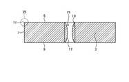
- FIG. 1is a perspective view showing an example of the covering tool of the present disclosure.
- FIG. 2is a schematic cross-sectional view showing an example of the covering tool of the present disclosure.
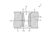
- FIG. 3is an enlarged schematic view of a cross section of the covering tool of the present disclosure.
- FIG. 4is an enlarged schematic view of a cross section of another form of the covering tool of the present disclosure.
- FIG. 5is an enlarged schematic view of a cross section of another form of the covering tool of the present disclosure.
- FIG. 6is a schematic enlarged view of the covering layer included in the covering tool of the present disclosure.
- FIG. 7is a plan view showing an example of the cutting tool of the present disclosure.
- FIG. 8is an enlarged schematic view of a cross section of the covering tool in the cutting tool of the present disclosure.
- the covering tool of the present disclosurewill be described in detail with reference to the drawings.
- each figure referred to belowis shown in a simplified manner only for the main members necessary for explaining the embodiment for convenience of explanation. Accordingly, the coated tools of the present disclosure may include any component not shown in each referenced figure. Further, the dimensions of the members in each drawing do not faithfully represent the dimensions of the actual constituent members and the dimensional ratio of each member. These points are the same for the cutting tool described later.
- the present disclosureprovides a covering tool with less abnormal damage and a cutting tool equipped with the covering tool.
- the coated tool of the present disclosurehas a substrate which is a cermet containing hard particles and a bonded phase.
- the hard particlesare, for example, TiCN, TiC, TiN, (TiM) CN (M is one or more selected from W, Nb, Ta, Mo, and V).
- the bonded phaseis mainly composed of an iron group metal such as Ni or Co.
- the main componentoccupies 50% by mass or more of the constituent components.
- the shape of the covering tool 1 of the present disclosuremay be, for example, a square plate shape.
- the first surface 5 which is the upper surface in FIG. 1is a so-called rake surface.
- the covering tool 1has a second surface 7 which is a side surface connected to the first surface 5.
- the covering tool 1has a third surface 9 which is a lower surface located opposite to the first surface 5.
- the second surface 7is connected to each of the first surface 5 and the third surface 9.
- the covering tool 1 of the present disclosurehas a cutting edge 11 located at least a part of the ridgeline where the first surface 5 and the second surface 7 intersect.
- the covering tool 1 of the present disclosurehas a cutting edge 11 located at least a part of the ridgeline where the rake face and the flank face intersect.
- the cutting edge 11has a fourth surface continuous with the first surface 5 and the second surface 7.
- the fourth surfacemay be a C surface (Chamfer surface) in which the corner portions of the first surface 5 and the second surface 7 are cut diagonally and linearly. Further, the fourth surface may be an R surface (round surface) in which the corners of the first surface 5 and the second surface 7 are rounded.
- the entire outer circumference of the first surface 5may be the cutting edge 11, but the covering tool 1 is not limited to such a configuration, and for example, one side on a quadrangular rake surface. Only, in other words, one having a cutting edge 11 on one of the four fourth surfaces may be used.
- the covering tool 1 of the present disclosurehas a through hole 15 penetrating the substrate 3 from the first surface 5 to the third surface 9.
- the inner wall 17 constituting the through hole 15has a bonded phase enriched layer 19 at least in the central portion 17a.
- the bonded phase enriched layer 19is a region containing hard particles and a bonded phase and having a higher content of the bonded phase than the inside of the substrate 3.
- the inside of the substrate 3means a portion separated from the surface of the substrate 3 by 500 ⁇ m or more.
- the bonded phase enriched layer 19does not have to be present in all of the inner walls 17 of the through hole 15, and may be located at least in the central portion 17a.
- the central portion 17ais in the middle when the through hole 15 is divided into nine equal parts in the depth direction. Further, the end portion 17b is an end when the through hole 15 is divided into nine equal parts in the depth direction.
- the thickness T1 of the coupled phase enriched layer 19 in the central portion 17a of the inner wall 17 constituting the through hole 15is the end portion of the inner wall 17 constituting the through hole 15. It is thicker than the thickness T2 of the bonded phase enriched layer 19 in 17b.
- the thickness T1 of the bound phase enriched layer 19 in the central portion 17a and the thickness T2 of the coupled phase enriched layer 19 in the end portion 17bare average values, respectively.
- the thickness T1 and the thickness T2may be measured by observing the cross section of the covering tool 1 with a metallurgical microscope or an electron microscope. It is not necessary that the bonded phase enriched layer 19 is present at the end portion 17b.
- the covering tool 1 of the present disclosurehas such a configuration, it is possible to prevent the covering tool 1 from being abnormally damaged starting from the inner wall 17 to which a large force is applied when fixing to a holder (not shown).
- FIG. 6is a schematic enlarged view of the covering layer included in the covering tool 1 of the present disclosure. As shown in FIG. 6, the covering tool 1 has a covering layer 30.
- the coating layer 30is located at least on the bonded phase enriched layer 19.
- the covering layer 30may be located on the first surface 5 or may be located on a surface other than the first surface 5 of the substrate 3.
- the covering layer 30improves characteristics such as wear resistance and chipping resistance of the covering tool 1 in cutting.
- the covering layer 30has a first layer 31 and a second layer 32.
- the first layer 31is located on the first surface 5 and contains cubic titanium nitride. Further, the second layer 32 is located in contact with the first layer 31.
- the second layer 32may contain, for example, aluminum oxide (Al 2 O 3 ).
- a titanium nitride layer 33may be provided between the first layer 31 and the substrate 3. With such a configuration, the bondability between the substrate 3 and the first layer 31 is high.
- the first layer 31has a titanium nitride titanium layer 34.
- the first layer 31may contain, for example, carbides, nitrides, oxides, carbonic acid oxides, and carbonic acid nitrogen oxides of titanium. Further, the first layer 31 may have a single layer structure as long as it contains cubic titanium nitride, or may have a structure in which a plurality of layers are laminated.
- the main components of the titanium nitride layer 33 and the titanium nitride layer 34are titanium nitride and titanium carbonitride, respectively.
- the "principal component”means that the component has the largest mass% value as compared with other components.
- the titanium nitride layer 33 and the titanium nitride layer 34may contain components other than titanium nitride and titanium carbonitride, respectively.
- the covering layer 30may be composed of only the first layer 31 and the second layer 32, or may have a layer other than these layers. For example, another layer may be present between the substrate 3 and the first layer 31, and another layer may be present on the second layer 32.
- the first layer 31is located on the bonded phase enriched layer 19.
- the first layer 31has a portion having a higher hardness than the bonded phase enriched layer 19. Having such a configuration increases the wear resistance of the clamp portion.
- the first layer 31may be formed by a CVD method or a PVD method.
- the first layer 31is measured within the inclination angle classification range of 0 ° or more and 10 ° or less.
- the tilt angle distribution in which the highest peak of the tilt angle appears and the total ratio of the degrees existing in the tilt angle division of 0 ° or more and 10 ° or lessis 45% or more and 60% or less of the total degrees in the tilt angle number distribution graph. The graph is shown.
- the hardness of the coating layer 30increases. Therefore, in the covering tool 1 in this case, a layer having a relatively high hardness (coating layer 30) is located on the surface layer portion, and a relatively soft layer (bonded phase enriched layer 19) is located at a position deeper than the covering layer 30. are doing.
- the coupling phase enriched layer 19 in the central portion 17ais suppressed in the contact between the central portion 17a in the inner wall 17 and the clamp 107. Since the local force applied to the substrate 3 is small due to the deformation, the covering tool 1 is not easily cracked and is not easily damaged abnormally.
- EBSDElectron Backscatter Diffraction
- the covering tool 1is cut so that the cross section of the through hole 15 appears, and the covering layer 30 is exposed.
- the surface on which the first layer 31 is exposedis polished to smooth the surface, and the measurement points are subjected to ion milling treatment.
- the polished surfacewhich is the cross section of the first layer 31 exposed in this way, is irradiated with an electron beam, and the inclination angle formed by the normal of the ⁇ 112 ⁇ surface is set at intervals of 0.1 ⁇ m in the range of about 40 ⁇ 25 ⁇ m 2 . taking measurement.
- Examples of the second layer 32 containing aluminum oxideinclude ⁇ -alumina ( ⁇ -Al 2 O 3 ), ⁇ -alumina ( ⁇ -Al 2 O 3 ) and ⁇ -alumina ( ⁇ -Al 2 O 3 ). Can be mentioned. Of these, when the second layer 32 contains ⁇ -alumina, the heat resistance of the covering tool 1 can be enhanced.
- the second layer 32may be configured to contain only one of the above compounds, or may be configured to contain a plurality of the above compounds.
- Which of the above compounds the aluminum oxide contained in the second layer 32 iscan be evaluated by, for example, performing X-ray diffraction (XRD) analysis and observing the distribution of peak values.
- XRDX-ray diffraction
- the first layer 31may contain a component other than titanium nitride.
- the second layer 32may contain a component other than aluminum oxide.
- the first layer 31may contain aluminum oxide.
- the second layer 32may contain a titanium compound such as titanium carbonitride. In such a case, the bondability of the first layer 31 and the second layer 32 is improved.
- the bonded phase enriched layer 19has a lower hardness than the substrate 3, and has a higher hardness than the metal shimidashi layer as described in Cited Document 1. Therefore, the bond phase enriched layer 19 is less deformed than the metal shimidashi layer.
- the size of the covering tool 1is not particularly limited, but for example, the length of one side of the rake face is set to about 3 to 20 mm. Further, the thickness of the covering tool 1 is set to, for example, about 1 to 20 mm. Further, in FIG. 1, the rectangular covering tool 1 is illustrated, but it may be triangular or disk-shaped, for example.
- the covering tool 1 of the present disclosuremay have a diameter-expanded portion 21 connected to the inner wall 17. There is a step at the boundary between the through hole 15 and the enlarged diameter portion 21.
- the bonded phase enriched layer 19does not exist on the inner wall of the enlarged diameter portion 21, but the coupled phase enriched layer 19 may also be present on the enlarged diameter portion 21.
- the enlarged diameter portion 21is not included in the through hole 15.
- the enlarged diameter portion 21is a so-called counterbore surface.
- the diameter of the enlarged diameter portion 21is 300 ⁇ m or more larger than the diameter of the through hole 15.
- the thickness T1 of the bonded phase enriched layer 19 in the central portion 17amay be 1 ⁇ m or more. Further, the thickness T1 may be 20 ⁇ m or less. According to such a configuration, abnormal damage of the covering tool 1 is suppressed.
- the thickness T1may be 3 ⁇ m or more. Further, the thickness T1 may be 10 ⁇ m or less.
- the thickness T2 of the bonded phase enriched layer 19 at the end portion 17bmay be 0.2 ⁇ m or more. Further, the thickness T2 may be 6 ⁇ m or less. According to such a configuration, abnormal damage of the covering tool 1 is suppressed.
- the diameter R1 at the central portion 17amay be larger than the diameter R2 at the end portion 17b. With such a configuration, the contact area between the clamp and the inner wall 17 becomes large, and the clamping force increases.
- the diameter R1 at the central portion 17amay be 5 ⁇ m or more and 30 ⁇ m or less larger than the diameter R2 at the end portion 17b. With such a configuration, abnormal damage to the covering tool 1 is suppressed.
- the hardness of the bonded phase enriched layer 19 in the central portion 17amay be 10 GPa or more and 20 GPa or less. According to such a configuration, when the clamp pins come into contact with each other, the coupled phase enriched layer 19 is appropriately deformed and the clamping force is increased.
- the hardness of the bonded phase enriched layer 19 in the central portion 17amay be measured by measuring the exposed bonded phase enriched layer 19 in the cross section of the covering tool 1 by using a nanoindentation method.
- the bonded phase enriched layer 19 in the central portion 17amay have a metal layer (not shown) having a higher content of the bonded phase than the bonded phase enriched layer 19 on the through shaft side of the through hole 15.
- This metal layerdoes not include a hard layer and is composed only of metal. With such a configuration, the metal layer functions as a cushioning material between the clamp described later and the bonded phase enriched layer 19, so that abnormal damage to the covering tool 1 is suppressed.
- the thickness of the metal layermay be 0.3 ⁇ m or more and 2 ⁇ m or less.
- the raw material powder used in the production of the coated tool of the present disclosureis generally used in the production of cermet.
- the substratemay contain, for example, 40% by mass or more and 80% by mass or less of TiCN which is a hard particle, and 6% by mass or more and 30% by mass or less of Co which is a bonded phase. Further, in order to further improve the characteristics, the substrate may contain WC, TaC, NbC, Mo 2C , VC, ZrC and the like.
- the raw material having the above compositionis molded into a shape having a space to be a through hole after firing. Then, for example, firing is performed at a temperature of 1400 ° C. or higher and 1600 ° C. or lower. This firing atmosphere may be set to an N2 partial pressure atmosphere.
- the N2 partial pressureis 1 kPa or more
- the thickness of the bonded phase enriched layer after firingbecomes thick.
- the average particle diameter d50 of the hard particles used as a raw materialis 0.7 ⁇ m or less
- the bonded phasehas a metal layer having a higher content of the bonded phase than the bonded phase enriched layer on the through axis (not shown) side of the through hole. An enriched layer is obtained.
- the molding pressureis high during the above molding, deformation during firing can be suppressed.
- the molding pressureis reduced during molding, the diameter R1 at the central portion of the inner wall tends to be larger than the diameter R2 at the end portion. Since the relationship between the forming pressure and the deformation changes depending on the composition and the firing temperature, various combinations may be adjusted.
- a brush that rotates after firingis inserted into the through hole from both ends of the through hole to polish the inner wall of the through hole, and the thickness T1 of the bonded phase enriched layer at the central portion is the thickness of the bonded phase enriched layer at the end. Process it so that it is thicker than T2.
- the brushmay be inserted from both sides of the through hole, or may be inserted from one side in two steps.
- a coating layeris formed on the surface of the substrate by a chemical vapor deposition (CVD) method.
- CVDchemical vapor deposition
- the titanium nitride layer in the first layeris formed on the surface of the substrate.
- Hydrogen gasincludes titanium tetrachloride gas of 0.5% by volume or more and 10% by volume or less, nitrogen gas of 1% by volume or more and 60% by volume or less, and acetonitrile gas of 0.1% by volume or more and 3.0% by volume or less. And are mixed to prepare a first mixed gas. While introducing this first mixed gas into the chamber, the acetonitrile gas is increased by 0.4% by volume per hour from the start of film formation.
- the first mixed gasis introduced into the chamber at a gas partial pressure of 6 kPa or more and 12 kPa or less to form a titanium carbonitride layer containing MT-titanium nitride in a temperature range of 830 ° C. or higher and 870 ° C. or lower.
- the second layer 32is formed into a film.
- the film formation temperatureis 950 ° C. or higher and 1100 ° C. or lower
- the gas pressureis 5 kPa or higher and 20 kPa or lower
- the composition of the reaction gasis hydrogen gas, aluminum trichloride (AlCl 3 ) gas of 5% by volume or more and 15% by volume or less, and 0. .5% by volume or more and 2.5% by volume or less of hydrogen chloride (HCl) gas, 0.5% by volume or more and 5.0% by volume or less of carbon dioxide gas, and 0% by volume or more and 1% by volume or less of hydrogen sulfide ( H 2 S)
- HClhydrogen chloride
- H 2 Shydrogen sulfide
- the bonded phase enriched layermay be present in a region other than the through hole, for example, the first surface, the second surface, or the third surface, but if necessary, the bonded phase enriched layer may be present. May be removed.
- the cutting tool 101 of the present disclosureis, for example, a rod-shaped body extending from the first end (upper end in FIG. 7) to the second end (lower end in FIG. 7).
- the cutting tool 101includes a holder 105 having a pocket 103 on the first end side (tip side) and the above-mentioned covering tool 1 located in the pocket 103.
- the clamp 107is inserted into the through hole 15 (see FIG. 1) of the covering tool 1.
- the clamp 107is in direct or indirect contact with the coupled phase enrichment layer 19 (see FIG. 2) located at the central portion 17a.
- the indirect contact between the clamp 107 and the bonded phase enriched layer 19means a state in which a metal layer or a coating layer exists between the coupled phase enriched layer 19 and the clamp 107. Since the bonded phase enriched layer 19 with which the clamp 107 comes into contact is more easily deformed than the substrate 3, it is difficult to apply a strong force locally to the covering tool 1.
- the coupling phase enriched layer 19when the coupled phase enriched layer 19 is provided, the contact area between the clamp 107 and the coupled phase enriched layer 19 is large, so that the covering tool 1 is difficult to move in the pocket during cutting. Combined with such effects, the covering tool 1 of the present disclosure is unlikely to be abnormally damaged. Since the cutting tool 101 includes the covering tool 1, stable cutting can be performed for a long period of time.
- the pocket 103is a portion on which the covering tool 1 is mounted, and has a seating surface parallel to the lower surface of the holder 105 and a restraining side surface inclined with respect to the seating surface. Further, the pocket 103 is open on the first end side of the holder 105.
- the covering tool 1is located in the pocket 103. At this time, the lower surface of the covering tool 1 may be in direct contact with the pocket 103, or a sheet (not shown) may be sandwiched between the covering tool 1 and the pocket 103.
- the covering tool 1is attached to the holder 105 so that at least a part of the portion used as the cutting edge 11 at the ridge line where the rake surface and the flank surface intersect protrudes outward from the holder 105.
- the covering tool 1is attached to the holder 105 by the clamp 107. That is, by inserting the clamp 107 into the through hole 15 of the covering tool 1, inserting the tip of the clamp 107 into the screw hole (not shown) formed in the pocket 103, and screwing the screw portions together, the covering tool 1 is attached to the holder 105.
- Steel, cast iron, etc.can be used as the material of the holder 105.
- steel having high toughnessmay be used.
- the cutting tool 101 used for so-called turningis exemplified.
- the turning processinclude inner diameter processing, outer diameter processing, grooving processing, end face processing and the like.
- the cutting tool 101is not limited to the one used for turning.
- the covering tool 1 of the above embodimentmay be used for the cutting tool 101 used for milling.
- the covering tool of the present disclosurewill be described below.
- the substratewas prepared as follows. TiCN is 40% by mass, TiN is 12% by mass, WC is 20% by mass, NbC is 8% by mass, Co is 20% by mass, and other raw material powders containing unavoidable carbides.
- a tool-shaped molded body having a through holewas produced by adjusting the shape to a desired shape. These raw material powders are generally used in the production of cermets.
- the composition of the substrate of the present disclosureis also not special. Then, after removing the binder component, firing was performed in a nitrogen atmosphere of 3 kPa at a temperature of 1530 ° C. for 1 hour to obtain a coating tool provided with a bonded phase enriched layer having a metal layer on the inner wall of the through hole. rice field.
- the inner wall of the through holewas polished with a brush to prepare a covering tool having the configuration shown in Table 1.
- the polishing time by the brushis lengthened.
- the first surface, the second surface, and the third surfacewere blasted to remove the bonded phase enriched layer.
- Polishing with a brushwas performed by applying a polishing liquid of 0.1 to 3 ⁇ m diamond powder and lubricating oil to a pig bristle brush, and inserting the pig bristle brush into a through hole while rotating it. Then, a coating film was formed on the substrate based on the above-mentioned film forming step of the coating layer.
- the thickness at the center and the end of the bonded phase enriched layer, the diameter R1 at the center and R2 at the endwere measured by the cross section obtained by cutting the substrate in the thickness direction at the plane including the through shaft.
- the hardness of the bonded phase enriched layerwas lower than the hardness inside the substrate.
- the obtained covering toolwas put in the pocket of the holder, a clamp was inserted into the through hole of the covering tool, and the covering tool was fixed with this clamp. Then, a cutting test was conducted under the following conditions.
- Sample No.which does not have the configuration of the covering tool of the present disclosure. Abnormal damage occurred in 1, 2 and 9. Abnormal damage was suppressed in the covering tool of the present disclosure. In addition, the covering tool was well held by the holder, and the surface roughness of the machined work material was also good.
- the inclination angle of the first layer of the obtained covering toolwas measured by the backscattered electron diffraction method.
- the measuring methodis as described above. That is, first, the covering tool is cut so that the cross section of the through hole appears to expose the covering layer. Next, the second layer is removed by grinding, polishing or the like to expose the first layer. Next, the exposed surface of the first layer is polished to smooth the surface, and then the measurement site is subjected to ion milling treatment.
- the polished surfacewhich is the cross section of the first layer exposed in this way, is irradiated with an electron beam, and the inclination angle formed by the normal of the ⁇ 112 ⁇ surface is measured at intervals of 0.1 ⁇ m in the range of about 40 ⁇ 25 ⁇ m 2 . do. Then, the measurement inclination angle within the range of 0 ° or more and 45 ° or less is divided by the pitch of 0.25 °.
- the covering tool and the cutting tool provided with the covering tool described aboveare examples, and may have different configurations as long as they do not deviate from the gist of the present application.
Landscapes
- Chemical & Material Sciences (AREA)
- Chemical Kinetics & Catalysis (AREA)
- Engineering & Computer Science (AREA)
- Materials Engineering (AREA)
- Mechanical Engineering (AREA)
- Metallurgy (AREA)
- Organic Chemistry (AREA)
- Inorganic Chemistry (AREA)
- General Chemical & Material Sciences (AREA)
- Cutting Tools, Boring Holders, And Turrets (AREA)
- Chemical Vapour Deposition (AREA)
Abstract
Description
Translated fromJapanese本開示は、切削加工において用いられる被覆工具及びこれを備えた切削工具に関する。This disclosure relates to a covering tool used in cutting and a cutting tool equipped with the covering tool.
現在、切削工具や耐摩耗性部材、摺動部材等の耐摩耗性や摺動性、耐チッピング性を必要とする部材の基体として、チタン(Ti)を主成分とするサーメットが広く使われている。Currently, cermets containing titanium (Ti) as the main component are widely used as a substrate for members that require wear resistance, sliding property, and chipping resistance, such as cutting tools, wear-resistant members, and sliding members. There is.
例えば、特許文献1では、工具本体への取り付け用貫通孔を有する表面被覆炭窒化チタン基サーメット製切削インサートが記載されている。特許文献1においては、負荷の高い切削においても異常損傷が少ないインサートを提供するために、取り付け用貫通孔の内面に金属シミダシ層を設けることが記載されている。For example,
本開示の被覆工具は、硬質粒子と結合相とを含有するサーメットである基体と、前記基体の上に位置する被覆層とを具備する被覆工具である。被覆工具は、第1面と、第2面と、第1面および前記第2面の稜線の少なくとも一部に位置する切刃と、第1面の反対に位置する第3面と、第1面から第3面にわたる貫通孔と、を有する。貫通孔を構成する内壁は、少なくとも中央部に、基体の内部よりも結合相の含有率が高い結合相富化層を有する。中央部における結合相富化層の厚みT1は、内壁の端部における結合相富化層の厚みT2よりも厚い。被覆層は、チタン化合物を含有する第1層と、第1層の上に接して位置する、酸化アルミニウムを含有する第2層とを有する。貫通孔の断面研磨面において、第1層の表面の法線に対して第1層の結晶粒の結晶面である{112}面の法線がなす傾斜角を測定したとき、0°以上45°以下の範囲内にある測定傾斜角を0.25°のピッチ毎に区分するとともに、各区分内に存在する度数を集計してなる傾斜角度数分布グラフにおいて、最高ピークは、0°以上10°以下の範囲内に存在し、0°以上10°以下の範囲内に存在する度数の合計が、傾斜角度数分布グラフにおける度数全体の45%以上60%以下の割合を占める。The coating tool of the present disclosure is a coating tool including a substrate which is a cermet containing hard particles and a bonded phase, and a coating layer located on the substrate. The covering tool includes a first surface, a second surface, a cutting edge located at least a part of the ridgeline of the first surface and the second surface, a third surface located opposite to the first surface, and a first surface. It has a through hole extending from a surface to a third surface. The inner wall constituting the through hole has a bound phase enriched layer having a higher content of the bound phase than the inside of the substrate, at least in the central portion. The thickness T1 of the bonded phase enriched layer in the central portion is thicker than the thickness T2 of the bonded phase enriched layer at the end portion of the inner wall. The coating layer has a first layer containing a titanium compound and a second layer containing aluminum oxide, which is located in contact with the first layer. When measuring the inclination angle formed by the normal of the {112} plane, which is the crystal plane of the crystal grains of the first layer, with respect to the normal of the surface of the first layer on the cross-sectional polished surface of the through hole, it is 0 ° or more and 45. In the tilt angle number distribution graph, which divides the measured tilt angles within the range of ° or less for each pitch of 0.25 ° and aggregates the degrees existing in each classification, the maximum peak is 0 ° or more and 10 The total of the degrees existing in the range of ° or less and in the range of 0 ° or more and 10 ° or less occupies the ratio of 45% or more and 60% or less of the total degrees in the tilt angle number distribution graph.
<被覆工具>
以下、本開示の被覆工具について、図面を用いて詳細に説明する。但し、以下で参照する各図は、説明の便宜上、実施形態を説明する上で必要な主要部材のみを簡略化して示したものである。したがって、本開示の被覆工具は、参照する各図に示されていない任意の構成部材を備え得る。また、各図中の部材の寸法は、実際の構成部材の寸法及び各部材の寸法比率などを忠実に表したものではない。これらの点は、後述する切削工具においても同様である。<Covering tool>
Hereinafter, the covering tool of the present disclosure will be described in detail with reference to the drawings. However, each figure referred to below is shown in a simplified manner only for the main members necessary for explaining the embodiment for convenience of explanation. Accordingly, the coated tools of the present disclosure may include any component not shown in each referenced figure. Further, the dimensions of the members in each drawing do not faithfully represent the dimensions of the actual constituent members and the dimensional ratio of each member. These points are the same for the cutting tool described later.
切削加工において用いられる被覆工具においては、異常損傷が少ないことが望まれる。本開示は、異常損傷が少ない被覆工具及びこれを備えた切削工具を提供する。It is desirable that there is little abnormal damage in the covering tool used in cutting. The present disclosure provides a covering tool with less abnormal damage and a cutting tool equipped with the covering tool.
本開示の被覆工具は、硬質粒子と結合相とを含有するサーメットである基体を有する。硬質粒子は、例えば、TiCN、TiC、TiN、(TiM)CN(Mは、W、Nb、Ta、Mo、Vから選ばれる一種以上)である。結合相は、NiやCoなどの鉄族金属を主成分とする。なお、主成分とは、構成成分のうち50質量%以上を占めるものである。The coated tool of the present disclosure has a substrate which is a cermet containing hard particles and a bonded phase. The hard particles are, for example, TiCN, TiC, TiN, (TiM) CN (M is one or more selected from W, Nb, Ta, Mo, and V). The bonded phase is mainly composed of an iron group metal such as Ni or Co. The main component occupies 50% by mass or more of the constituent components.
図1、2に示すように、本開示の被覆工具1の形状は、例えば、四角板形状であってもよい。図1における上面である第1面5は、いわゆるすくい面である。また、被覆工具1は、第1面5に繋がる側面である第2面7を有している。As shown in FIGS. 1 and 2, the shape of the
被覆工具1は、第1面5の反対に位置する下面である第3面9を有している。第2面7は、第1面5及び第3面9のそれぞれにつながっている。The
本開示の被覆工具1は、第1面5と第2面7とが交わる稜線の少なくとも一部に位置する切刃11を有している。言い換えれば、本開示の被覆工具1は、すくい面と逃げ面とが交わる稜線の少なくとも一部に位置する切刃11を有している。切刃11は、第1面5と第2面7とに連続する第4面を有する。第4面は、第1面5と第2面7との角部を斜め且つ直線的に削ったC面(チャンファー面)であってもよい。また、第4面は、第1面5と第2面7との角部を丸めたR面(ラウンド面)であってもよい。The
被覆工具1においては、第1面5の外周の全体が切刃11となっていてもよいが、被覆工具1はこのような構成に限定されるものではなく、例えば、四角形のすくい面における一辺のみ、言い換えれば、4つの第4面のうちの一つに切刃11を有するものであってもよい。In the
本開示の被覆工具1は、第1面5から第3面9にわたり、基体3を貫通する貫通孔15を有している。図3に示すように、貫通孔15を構成する内壁17には、少なくとも中央部17aにおいて、結合相富化層19が存在している。結合相富化層19は、硬質粒子および結合相を含有し、基体3の内部よりも結合相の含有率の高い領域である。基体3の内部とは、基体3の表面から500μm以上離れた部分を意味する。結合相富化層19は、貫通孔15の内壁17の全てに存在する必要はなく、少なくとも中央部17aに位置していればよい。The
中央部17aは、貫通孔15を深さ方向に9等分したときの真ん中である。また、端部17bは、貫通孔15を深さ方向に9等分したときの端である。The
図3に示すように、本開示の被覆工具1において、貫通孔15を構成する内壁17の中央部17aにおける結合相富化層19の厚みT1は、貫通孔15を構成する内壁17の端部17bにおける結合相富化層19の厚みT2よりも厚い。中央部17aにおける結合相富化層19の厚みT1および端部17bにおける結合相富化層19の厚みT2とは、それぞれ平均値である。厚みT1および厚みT2は、被覆工具1の断面を金属顕微鏡や電子顕微鏡を用いて観察して測定するとよい。なお、端部17bにおいては、結合相富化層19が存在していなくともよい。As shown in FIG. 3, in the
本開示の被覆工具1は、このような構成を有することで、ホルダ(図示しない)への固定の際に大きな力が加わる内壁17を起点として被覆工具1が異常損傷することが抑制される。Since the
図6は、本開示の被覆工具1が有する被覆層の模式的な拡大図である。図6に示すように、被覆工具1は、被覆層30を有する。FIG. 6 is a schematic enlarged view of the covering layer included in the
被覆層30は、少なくとも結合相富化層19の上に位置している。被覆層30は、第1面5の上に位置していてもよく、また、基体3における第1面5以外の他の面の上に位置していてもよい。被覆層30は、切削加工における被覆工具1の耐摩耗性及び耐チッピング性などの特性を向上させる。The
被覆層30は、第1層31及び第2層32を有する。第1層31は、第1面5の上に位置しており、立方晶の炭窒化チタンを含有する。また、第2層32は、第1層31の上に接して位置している。第2層32は、例えば、酸化アルミニウム(Al2O3)を含有していてもよい。The
第1層31と基体3の間には、窒化チタン層33を有していてもよい。このような構成を有すると、基体3と第1層31との接合性が高い。A
第1層31は、炭窒化チタン層34を有している。第1層31には、炭窒化チタンのほかにも、例えば、チタンの炭化物、窒化物、酸化物、炭酸化物及び炭窒酸化物を含有していてもよい。また、第1層31は、立方晶の炭窒化チタンを含有しているものであれば、単層の構成であってもよく、また、複数の層が積層された構成であってもよい。The
窒化チタン層33および炭窒化チタン層34の主成分は、それぞれ窒化チタンおよび炭窒化チタンである。「主成分」とは、他の成分と比較して質量%の値が最も大きい成分であることを意味している。窒化チタン層33および炭窒化チタン層34は、それぞれ窒化チタンおよび炭窒化チタン以外の成分を含有していてもよい。The main components of the
被覆層30は、第1層31及び第2層32のみによって構成されていてもよく、また、これらの層以外の層を有していてもよい。例えば、基体3及び第1層31の間に別の層が存在していてもよく、また、第2層32の上に別の層が存在していてもよい。The
第1層31は、結合相富化層19の上に位置している。第1層31は、結合相富化層19よりも硬度が高い部分を有する。このような構成を有すると、クランプ部における耐摩耗性が増す。第1層31は、CVD法やPVD法によって形成されるものであってもよい。The
第1層31は、表面の法線に対して結晶粒の結晶面である{112}面の法線がなす傾斜角を測定したとき、0°以上10°以下の傾斜角区分範囲内に測定傾斜角の最高ピークが現れ、かつ0°以上10°以下の傾斜角区分内に存在する度数の合計割合が、傾斜角度数分布グラフにおける度数全体の45%以上60%以下となる傾斜角度数分布グラフを示す。When the inclination angle formed by the normal of the {112} plane, which is the crystal plane of the crystal grain, is measured with respect to the normal of the surface, the
0°以上10°以下の傾斜角区分内に存在する度数の合計割合が、傾斜角度数分布グラフにおける度数全体の45%以上60%以下であると、被覆層30の硬度が上昇する。したがって、この場合の被覆工具1は、表層部分に比較的硬度が高い層(被覆層30)が位置し、被覆層30よりも深い位置に比較的柔らかい層(結合相富化層19)が位置している。このように構成することで、被覆工具1をクランプ107によってホルダ105に固定する際に、内壁17における中央部17aとクランプ107との接触において、中央部17aにおける結合相富化層19の抑制された変形により、基体3にかかる局所的な力が小さいため、被覆工具1が割れにくく、異常損傷しにくい。When the total ratio of the degrees existing in the inclination angle division of 0 ° or more and 10 ° or less is 45% or more and 60% or less of the total degrees in the inclination angle number distribution graph, the hardness of the
上記の傾斜角の測定には、例えば、後方散乱電子回折(EBSD:Electron Backscatter Diffraction)法が用いられ得る。後方散乱電子回折法を用いた測定の一例について以下に示す。For the measurement of the above inclination angle, for example, a backscattered electron diffraction (EBSD: Electron Backscatter Diffraction) method can be used. An example of the measurement using the backscattered electron diffraction method is shown below.
まず、貫通孔15の断面が現れるよう被覆工具1を切断して被覆層30を露出させる。次に、第1層31を露出させた面に対して研磨加工を施して表面を平滑化させ、測定箇所にイオンミリング処理を行う。First, the
このようにして露出させた第1層31の断面である研磨面に電子線を照射し、約40×25μm2の範囲において0.1μmの間隔で{112}面の法線がなす傾斜角を測定する。次に、測定傾斜角のうち0°以上45°以下の範囲内にある測定傾斜角を0.25°のピッチで区分するとよい。The polished surface, which is the cross section of the
酸化アルミニウムを含有する第2層32の例としては、α-アルミナ(α-Al2O3)、γ-アルミナ(γ-Al2O3)及びκ-アルミナ(κ-Al2O3)等が挙げられる。これらのうち、第2層32がα-アルミナを含有している場合には、被覆工具1の耐熱性を高めることができる。第2層32は、上記の化合物のいずれか1つのみを含有する構成であってもよく、また、上記の化合物のうち複数を含有する構成であってもよい。Examples of the
第2層32に含有されている酸化アルミニウムが上記の化合物のいずれであるかは、例えば、X線回折(XRD)分析を行い、ピーク値の分布を観察することにより評価することができる。Which of the above compounds the aluminum oxide contained in the
第1層31は、炭窒化チタン以外の成分を含有していてもよい。また、第2層32は、酸化アルミニウム以外の成分を含有していてもよい。例えば、第1層31は、酸化アルミニウムを含有していてもよい。また、第2層32は、炭窒化チタンなどのチタン化合物を含有していてもよい。このような場合、第1層31及び第2層32の接合性が向上する。The
結合相富化層19は、基体3に比べて硬度が低く、引用文献1に記載されているような金属シミダシ層よりも硬度が高い。そのため、結合相富化層19は、金属シミダシ層よりも変形が抑制されている。The bonded phase enriched
上述の構成を有するため、被覆工具1をクランプによってホルダに固定する際に、内壁17における中央部17aとクランプとの接触において、中央部17aにおける結合相富化層19の抑制された変形により、基体3にかかる局所的な力が小さいため、被覆工具1が割れにくく、異常損傷しにくい。Due to the above-mentioned configuration, when the
被覆工具1の大きさは特に限定されるものではないが、例えば、すくい面の一辺の長さが3~20mm程度に設定される。また、被覆工具1の厚みは、例えば1~20mm程度に設定される。また、図1においては、四角形状の被覆工具1を例示したが、例えば、三角形状や円盤状であってもよい。The size of the
また、図4に示すように、本開示の被覆工具1は、内壁17に繋がる拡径部21を有していてもよい。貫通孔15と拡径部21との境には段差がある。なお、図4に示す例では、拡径部21の内壁には、結合相富化層19が存在しないが、拡径部21にも結合相富化層19があってもよい。本開示の被覆工具1において、拡径部21は、貫通孔15に含まれない。拡径部21は、いわゆる、ざぐり面である。拡径部21の直径は、貫通孔15の直径よりも、300μm以上大きい。Further, as shown in FIG. 4, the
中央部17aにおける結合相富化層19の厚みT1は、1μm以上であってもよい。また、厚みT1は、20μm以下であってもよい。このような構成によれば、被覆工具1の異常損傷が抑制される。厚みT1は、3μm以上であってもよい。また、厚みT1は10μm以下であってもよい。The thickness T1 of the bonded phase enriched
端部17bにおける結合相富化層19の厚みT2は、0.2μm以上であってもよい。また、厚みT2は6μm以下であってもよい。このような構成によれば、被覆工具1の異常損傷が抑制される。The thickness T2 of the bonded phase enriched
図5に示すように、中央部17aにおける直径R1は、端部17bにおける直径R2よりも大きくてもよい。このような構成を有すると、クランプと、内壁17との接触面積が大きくなり、クランプ力が増す。As shown in FIG. 5, the diameter R1 at the
中央部17aにおける直径R1は、端部17bにおける直径R2よりも5μm以上、30μm以下大きくてもよい。このような構成を有すると被覆工具1の異常損傷が抑制される。The diameter R1 at the
中央部17aにおける結合相富化層19の硬度は、10GPa以上、20GPa以下であってもよい。このような構成によれば、クランプピンが接触した際に、結合相富化層19が適度に変形し、クランプ力が増す。中央部17aにおける結合相富化層19の硬度は、被覆工具1の断面において、露出した結合相富化層19を、ナノインデンテーション法を用いて測定するとよい。The hardness of the bonded phase enriched
中央部17aにおける結合相富化層19は、貫通孔15の貫通軸側に結合相富化層19よりも結合相の含有量が多い金属層(図示しない)を有していてもよい。この金属層は、硬質層を含まず、金属のみから構成されている。このような構成を有すると、金属層が、後述するクランプと、結合相富化層19の間で緩衝材として機能するため、被覆工具1の異常損傷が抑制される。金属層の厚みは、0.3μm以上、2μm以下であってもよい。The bonded phase enriched
<被覆工具の製造方法>
以下に本開示の被覆工具の製造方法を説明する。<Manufacturing method of covering tool>
The manufacturing method of the covering tool of the present disclosure will be described below.
本開示の被覆工具の製造に用いられる原料粉末は、一般的にサーメットの製造で用いられるものである。The raw material powder used in the production of the coated tool of the present disclosure is generally used in the production of cermet.
基体は、例えば、硬質粒子であるTiCNを40質量%以上、80質量%以下含有し、結合相であるCoを6質量%以上、30質量%以下、含有するものであってもよい。また、さらに特性向上のために、基体は、WC、TaC、NbC、Mo2C、VC、ZrCなどを含有してもよい。The substrate may contain, for example, 40% by mass or more and 80% by mass or less of TiCN which is a hard particle, and 6% by mass or more and 30% by mass or less of Co which is a bonded phase. Further, in order to further improve the characteristics, the substrate may contain WC, TaC, NbC, Mo2C , VC, ZrC and the like.
上述の組成を有する原材料を用いて、焼成後に貫通孔となる空間を有する形状に成形する。その後、例えば、1400℃以上、1600℃以下の温度で焼成する。この焼成雰囲気をN2分圧雰囲気下としてもよい。Using the raw material having the above composition, it is molded into a shape having a space to be a through hole after firing. Then, for example, firing is performed at a temperature of 1400 ° C. or higher and 1600 ° C. or lower. This firing atmosphere may be set to anN2 partial pressure atmosphere.
N2分圧を1kPa以上にすると、焼成後の結合相富化層の厚みは厚くなる。また、原料として用いる硬質粒子の平均粒子径d50を0.7μm以下とすると貫通孔の貫通軸(図示しない)側に結合相富化層よりも結合相の含有量が多い金属層を有する結合相富化層が得られる。When theN2 partial pressure is 1 kPa or more, the thickness of the bonded phase enriched layer after firing becomes thick. Further, when the average particle diameter d50 of the hard particles used as a raw material is 0.7 μm or less, the bonded phase has a metal layer having a higher content of the bonded phase than the bonded phase enriched layer on the through axis (not shown) side of the through hole. An enriched layer is obtained.
なお、上記の成形時に、成形圧が大きいと焼成時の変形を抑制することができる。一方、成形時に成形圧を小さくすると、内壁の中央部における直径R1が、端部における直径R2よりも大きくなりやすい。成形圧と変形の関係は、組成や焼成温度によって変化するため、種々組み合わせて調整するとよい。If the molding pressure is high during the above molding, deformation during firing can be suppressed. On the other hand, if the molding pressure is reduced during molding, the diameter R1 at the central portion of the inner wall tends to be larger than the diameter R2 at the end portion. Since the relationship between the forming pressure and the deformation changes depending on the composition and the firing temperature, various combinations may be adjusted.
例えば、焼成後に回転するブラシを貫通孔の両端部から貫通孔に挿入して貫通孔の内壁を研磨し、中央部における結合相富化層の厚みT1が端部における結合相富化層の厚みT2よりも厚くなるように加工する。なお、ブラシは貫通孔の両側から挿入してもよく、片方から2度に分けて挿入してもよい。For example, a brush that rotates after firing is inserted into the through hole from both ends of the through hole to polish the inner wall of the through hole, and the thickness T1 of the bonded phase enriched layer at the central portion is the thickness of the bonded phase enriched layer at the end. Process it so that it is thicker than T2. The brush may be inserted from both sides of the through hole, or may be inserted from one side in two steps.
次に、基体の表面に、化学気相蒸着(CVD)法によって被覆層を成膜する。まず、基体の表面に、第1層における炭窒化チタン層を成膜する。水素ガスに、0.5体積%以上10体積%以下の四塩化チタンガスと、1体積%以上、60体積%以下の窒素ガスと、0.1体積%以上3.0体積%以下のアセトニトリルガスとを混合し、第1混合ガスを作製する。この第1混合ガスをチャンバ内に導入しながら成膜開始時から、アセトニトリルガスを毎時0.4体積%増加させる。このとき第1混合ガスを、6kPa以上12kPa以下のガス分圧でチャンバ内に導入し、830℃以上870℃以下の温度域でMT-炭窒化チタンを含有する炭窒化チタン層を成膜する。Next, a coating layer is formed on the surface of the substrate by a chemical vapor deposition (CVD) method. First, the titanium nitride layer in the first layer is formed on the surface of the substrate. Hydrogen gas includes titanium tetrachloride gas of 0.5% by volume or more and 10% by volume or less, nitrogen gas of 1% by volume or more and 60% by volume or less, and acetonitrile gas of 0.1% by volume or more and 3.0% by volume or less. And are mixed to prepare a first mixed gas. While introducing this first mixed gas into the chamber, the acetonitrile gas is increased by 0.4% by volume per hour from the start of film formation. At this time, the first mixed gas is introduced into the chamber at a gas partial pressure of 6 kPa or more and 12 kPa or less to form a titanium carbonitride layer containing MT-titanium nitride in a temperature range of 830 ° C. or higher and 870 ° C. or lower.
次に、第2層32を成膜する。成膜温度を950℃以上1100℃以下、ガス圧を5kPa以上20kPa以下とし、反応ガスの組成が、水素ガスに、5体積%以上15体積%以下の三塩化アルミニウム(AlCl3)ガスと、0.5体積%以上2.5体積%以下の塩化水素(HCl)ガスと、0.5体積%以上5.0体積%以下の二酸化炭素ガスと、0体積%以上1体積%以下の硫化水素(H2S)ガスとを混合して、第2混合ガスを作製する。第2混合ガスをチャンバ内に導入し、第2層32を成膜する。これにより、本開示の被覆工具1を得ることができる。Next, the
なお、焼成後の時点で、貫通孔以外の領域、例えば、第1面、第2面や第3面において結合相富化層が存在する場合があるが、必要に応じて結合相富化層を除去してもよい。At the time after firing, the bonded phase enriched layer may be present in a region other than the through hole, for example, the first surface, the second surface, or the third surface, but if necessary, the bonded phase enriched layer may be present. May be removed.
<切削工具>
次に、本開示の切削工具について図面を用いて説明する。<Cutting tool>
Next, the cutting tool of the present disclosure will be described with reference to the drawings.
本開示の切削工具101は、図7に示すように、例えば、第1端(図7における上端)から第2端(図7における下端)に向かって延びる棒状体である。切削工具101は、図7に示すように、第1端側(先端側)にポケット103を有するホルダ105と、ポケット103に位置する上記の被覆工具1とを備えている。As shown in FIG. 7, the
また、図8に示すように、被覆工具1の貫通孔15(図1参照)には、クランプ107が挿入されている。図8に示す例では、クランプ107は、中央部17aに位置する結合相富化層19(図2参照)と直接または間接的に接触している。なお、間接的にクランプ107と結合相富化層19が接触するとは、結合相富化層19とクランプ107との間に金属層や被覆層が存在する状態を意味する。クランプ107が接触する結合相富化層19は、基体3よりも変形しやすいため、被覆工具1に局所的に強い力がかかりにくい。また、結合相富化層19を有すると、クランプ107と結合相富化層19との接触面積が大きいため、被覆工具1が切削時にポケット内で動きにくい。このような効果が相まって、本開示の被覆工具1は、異常損傷しにくい。切削工具101は、被覆工具1を備えているため、長期に渡り安定した切削加工を行うことができる。Further, as shown in FIG. 8, the
ポケット103は、被覆工具1が装着される部分であり、ホルダ105の下面に対して平行な着座面と、着座面に対して傾斜する拘束側面とを有している。また、ポケット103は、ホルダ105の第1端側において開口している。The
ポケット103には被覆工具1が位置している。このとき、被覆工具1の下面がポケット103に直接に接していてもよく、また、被覆工具1とポケット103との間にシート(不図示)が挟まれていてもよい。The
被覆工具1は、すくい面及び逃げ面が交わる稜線における切刃11として用いられる部分の少なくとも一部がホルダ105から外方に突出するようにホルダ105に装着される。本実施形態においては、被覆工具1は、クランプ107によって、ホルダ105に装着されている。すなわち、被覆工具1の貫通孔15にクランプ107を挿入し、このクランプ107の先端をポケット103に形成されたネジ孔(不図示)に挿入してネジ部同士を螺合させることによって、被覆工具1がホルダ105に装着されている。The
ホルダ105の材質としては、鋼、鋳鉄などを用いることができる。これらの部材の中で靱性の高い鋼を用いてもよい。Steel, cast iron, etc. can be used as the material of the
本実施形態においては、いわゆる旋削加工に用いられる切削工具101を例示している。旋削加工としては、例えば、内径加工、外径加工、溝入れ加工及び端面加工などが挙げられる。なお、切削工具101としては旋削加工に用いられるものに限定されない。例えば、転削加工に用いられる切削工具101に上記の実施形態の被覆工具1を用いてもよい。In this embodiment, the
以下に、本開示の被覆工具について、説明する。The covering tool of the present disclosure will be described below.
基体は、以下のように作製した。TiCNを40質量%、TiNを12質量%、WCを20質量%、NbCを8質量%、Coを20質量%、その他不可避炭化物を含む原料粉末原料粉末にバインダーを添加した後、プレス成型によって、所望の形状に整え、貫通孔を有する工具形状の成形体を作製した。これらの原料粉末は、一般的に、サーメットの製造で用いられるものである。本開示の基体の組成も特別なものではない。その後、バインダー成分を除去した後、3kPaの窒素雰囲気で、1530℃の温度で1時間保持する条件で焼成し、貫通孔の内壁に金属層を有する結合相富化層を具備する被覆工具を得た。The substrate was prepared as follows. TiCN is 40% by mass, TiN is 12% by mass, WC is 20% by mass, NbC is 8% by mass, Co is 20% by mass, and other raw material powders containing unavoidable carbides. A tool-shaped molded body having a through hole was produced by adjusting the shape to a desired shape. These raw material powders are generally used in the production of cermets. The composition of the substrate of the present disclosure is also not special. Then, after removing the binder component, firing was performed in a nitrogen atmosphere of 3 kPa at a temperature of 1530 ° C. for 1 hour to obtain a coating tool provided with a bonded phase enriched layer having a metal layer on the inner wall of the through hole. rice field.
その後、貫通孔の内壁をブラシで研磨して、表1に示す構成の被覆工具を作製した。なお、結合相富化層が存在しない、あるいは結合相富化層の厚みが薄い部分は、ブラシによる研磨時間を長くしたものである。
なお、いずれの被覆工具も第1面、第2面、第3面をブラスト処理して、結合相富化層を除去した。In each of the covering tools, the first surface, the second surface, and the third surface were blasted to remove the bonded phase enriched layer.
ブラシによる研磨は、豚毛ブラシに0.1~3μmのダイヤモンド粉末と潤滑油を混ぜた研磨液を塗布し、この豚毛ブラシを回転させながら、貫通孔に挿入して行った。その後、基体に対して前述の被覆層の成膜工程に基づいて被覆層を成膜した。Polishing with a brush was performed by applying a polishing liquid of 0.1 to 3 μm diamond powder and lubricating oil to a pig bristle brush, and inserting the pig bristle brush into a through hole while rotating it. Then, a coating film was formed on the substrate based on the above-mentioned film forming step of the coating layer.
結合相富化層の中央部および端部における厚み、中央部における直径R1および端部におけるR2は、基体を厚さ方向に貫通軸を含む面で切断して得られた断面で測定した。The thickness at the center and the end of the bonded phase enriched layer, the diameter R1 at the center and R2 at the end were measured by the cross section obtained by cutting the substrate in the thickness direction at the plane including the through shaft.
また、被覆工具の断面を用いて基体の内部における硬度、結合相富化層の硬度を測定したところ、結合相富化層の硬度は基体の内部における硬度よりも低かった。Further, when the hardness inside the substrate and the hardness of the bonded phase enriched layer were measured using the cross section of the covering tool, the hardness of the bonded phase enriched layer was lower than the hardness inside the substrate.
得られた被覆工具をホルダのポケットに入れ、被覆工具の貫通孔にクランプを挿入して、このクランプで被覆工具を固定した。そして、以下の条件で、切削試験を行った。The obtained covering tool was put in the pocket of the holder, a clamp was inserted into the through hole of the covering tool, and the covering tool was fixed with this clamp. Then, a cutting test was conducted under the following conditions.
<耐欠損試験>
被削材:SCM435 4本溝(5mm幅)付き
切削速度:300m/min
送り:0.3mm/rev
切込み:0.5mm
切削状態:湿式
評価方法:10000回の衝撃を加えた後のチッピングや欠損の状態の有無について判断した。<Defective resistance test>
Work material: SCM435 with 4 grooves (5 mm width) Cutting speed: 300 m / min
Feed: 0.3mm / rev
Notch: 0.5 mm
Cutting state: Wet evaluation method: The presence or absence of chipping or chipping after applying an impact of 10,000 times was judged.
本開示の被覆工具の構成を有さない、試料No.1、2、9は、異常損傷が発生した。本開示の被覆工具は、異常損傷が抑制された。また、被覆工具がホルダによく保持されており、加工した被削材の面粗度も良好であった。Sample No. which does not have the configuration of the covering tool of the present disclosure. Abnormal damage occurred in 1, 2 and 9. Abnormal damage was suppressed in the covering tool of the present disclosure. In addition, the covering tool was well held by the holder, and the surface roughness of the machined work material was also good.
また、得られた被覆工具の第1層の傾斜角を後方散乱電子回折法により測定した。測定方法については、上述した通りである。すなわち、まず、貫通孔の断面が現れるよう被覆工具を切断して被覆層を露出させる。次に、第2層を研削、研磨等により除去して第1層を露出させる。次に、第1層を露出させた面に対して研磨加工を施して表面を平滑化させた後、測定箇所にイオンミリング処理を行う。このようにして露出させた第1層の断面である研磨面に電子線を照射し、約40×25μm2の範囲において0.1μmの間隔で{112}面の法線がなす傾斜角を測定する。そして、0°以上45°以下の範囲内にある測定傾斜角を0.25°のピッチで区分する。Moreover, the inclination angle of the first layer of the obtained covering tool was measured by the backscattered electron diffraction method. The measuring method is as described above. That is, first, the covering tool is cut so that the cross section of the through hole appears to expose the covering layer. Next, the second layer is removed by grinding, polishing or the like to expose the first layer. Next, the exposed surface of the first layer is polished to smooth the surface, and then the measurement site is subjected to ion milling treatment. The polished surface, which is the cross section of the first layer exposed in this way, is irradiated with an electron beam, and the inclination angle formed by the normal of the {112} surface is measured at intervals of 0.1 μm in the range of about 40 × 25 μm2 . do. Then, the measurement inclination angle within the range of 0 ° or more and 45 ° or less is divided by the pitch of 0.25 °.
なお、表1における試験では、全ての試料の0°以上10°以下の範囲内に存在する度数の合計は、前記傾斜角度数分布グラフにおける度数全体の58%であった。In the test shown in Table 1, the total frequency of all the samples existing in the range of 0 ° or more and 10 ° or less was 58% of the total frequency in the tilt angle distribution graph.
以上説明した、本開示の被覆工具及びこれを備えた切削工具は、一例であり、本願の要旨を逸脱しない限り、異なる構成を有していてもよい。The covering tool and the cutting tool provided with the covering tool described above are examples, and may have different configurations as long as they do not deviate from the gist of the present application.
1・・・被覆工具
3・・・基体
5・・・第1面
7・・・第2面
9・・・第3面
11・・・切刃
15・・・貫通孔
17・・・内壁
17a・・中央部
17b・・端部
19・・・結合相富化層
21・・・拡径部
T1・・・中央部における結合相富化層の厚み
T2・・・端部における結合相富化層の厚み
R1・・・中央部における直径
R2・・・端部における直径
101・・・切削工具
103・・・ポケット
105・・・ホルダ
107・・・クランプ1 ... Covering
Claims (8)
Translated fromJapanese該被覆工具は、
第1面と、
第2面と、
前記第1面および前記第2面の稜線の少なくとも一部に位置する切刃と、
前記第1面の反対に位置する第3面と、前記第1面から前記第3面にわたる貫通孔と、を有し、
前記貫通孔を構成する内壁は、少なくとも中央部に、前記基体の内部よりも前記結合相の含有率が高い結合相富化層を有し、
前記中央部における前記結合相富化層の厚みT1は、前記内壁の端部における前記結合相富化層の厚みT2よりも厚く、
前記被覆層は、チタン化合物を含有する第1層と、該第1層の上に接して位置する、酸化アルミニウムを含有する第2層とを有し、
前記貫通孔の断面研磨面において、前記第1層の表面の法線に対して前記第1層の結晶粒の結晶面である{112}面の法線がなす傾斜角を測定したとき、0°以上45°以下の範囲内にある測定傾斜角を0.25°のピッチ毎に区分するとともに、各区分内に存在する度数を集計してなる傾斜角度数分布グラフにおいて、最高ピークは、0°以上10°以下の範囲内に存在し、前記0°以上10°以下の範囲内に存在する度数の合計が、前記傾斜角度数分布グラフにおける度数全体の45%以上60%以下の割合を占める、被覆工具。A coating tool comprising a substrate, which is a cermet containing hard particles and a bonded phase, and a coating layer located on the substrate.
The covering tool is
The first side and
The second side and
A cutting edge located at least a part of the ridgeline of the first surface and the second surface,
It has a third surface located opposite to the first surface and a through hole extending from the first surface to the third surface.
The inner wall constituting the through hole has a bound phase enriched layer having a higher content of the bound phase than the inside of the substrate, at least in the central portion.
The thickness T1 of the bonded phase enriched layer in the central portion is thicker than the thickness T2 of the bonded phase enriched layer at the end portion of the inner wall.
The coating layer has a first layer containing a titanium compound and a second layer containing aluminum oxide, which is located in contact with the first layer.
When the inclination angle formed by the normal of the {112} plane, which is the crystal plane of the crystal grain of the first layer, is measured with respect to the normal of the surface of the first layer on the cross-sectional polished surface of the through hole, it is 0. In the tilt angle number distribution graph, which divides the measurement tilt angle within the range of ° or more and 45 ° or less for each pitch of 0.25 ° and aggregates the degrees existing in each classification, the maximum peak is 0. The total of the degrees existing in the range of ° or more and 10 ° or less and in the range of 0 ° or more and 10 ° or less occupies the ratio of 45% or more and 60% or less of the total degrees in the inclination angle number distribution graph. , Covering tool.
前記ポケットに位置する請求項1~7のいずれか一つに記載の被覆工具と、
該被覆工具の前記貫通孔に挿入されたクランプと、を有する切削工具。A holder having a length extending from the first end to the second end and having a pocket located on the first end side.
The covering tool according to any one of claims 1 to 7 located in the pocket, and the covering tool.
A cutting tool having a clamp inserted into the through hole of the covering tool.
Priority Applications (3)
| Application Number | Priority Date | Filing Date | Title |
|---|---|---|---|
| JP2022557382AJP7523567B2 (en) | 2020-10-21 | 2021-10-05 | Coated tool and cutting tool equipped with same |
| CN202180069967.3ACN116323053A (en) | 2020-10-21 | 2021-10-05 | Coated cutting tool and cutting tool provided with same |
| DE112021005562.3TDE112021005562T5 (en) | 2020-10-21 | 2021-10-05 | COATED TOOL AND CUTTING TOOL INCLUDING THE COATED TOOL |
Applications Claiming Priority (2)
| Application Number | Priority Date | Filing Date | Title |
|---|---|---|---|
| JP2020-177013 | 2020-10-21 | ||
| JP2020177013 | 2020-10-21 |
Publications (1)
| Publication Number | Publication Date |
|---|---|
| WO2022085429A1true WO2022085429A1 (en) | 2022-04-28 |
Family
ID=81289728
Family Applications (1)
| Application Number | Title | Priority Date | Filing Date |
|---|---|---|---|
| PCT/JP2021/036769CeasedWO2022085429A1 (en) | 2020-10-21 | 2021-10-05 | Coated tool and cutting tool provided with same |
Country Status (4)
| Country | Link |
|---|---|
| JP (1) | JP7523567B2 (en) |
| CN (1) | CN116323053A (en) |
| DE (1) | DE112021005562T5 (en) |
| WO (1) | WO2022085429A1 (en) |
Citations (7)
| Publication number | Priority date | Publication date | Assignee | Title |
|---|---|---|---|---|
| JPS58199841A (en)* | 1982-05-18 | 1983-11-21 | Nippon Oil & Fats Co Ltd | Throwaway tip of sintered body having high hardness for cutting tool and its preparation |
| DE29506825U1 (en)* | 1994-09-30 | 1995-07-20 | TIGRA Hartstoff GmbH, 86405 Meitingen | Tungsten carbide plates, in particular cutting plates, with precision bores |
| JP2008501539A (en)* | 2004-06-02 | 2008-01-24 | サンドビック インテレクチュアル プロパティー アクティエボラーグ | Indexable cutting insert and manufacturing method thereof |
| JP2009107059A (en)* | 2007-10-30 | 2009-05-21 | Kyocera Corp | Cutting tool, cutting insert, and method of manufacturing cutting insert |
| JP2012245581A (en)* | 2011-05-26 | 2012-12-13 | Mitsubishi Materials Corp | Cutting insert made from surface coated titanium carbon nitride-based cermet, and method for manufacturing the same |
| JP2020146820A (en)* | 2019-03-15 | 2020-09-17 | 三菱マテリアル株式会社 | Cutting tool with hard coating layer exhibiting excellent chipping resistance |
| WO2020218241A1 (en)* | 2019-04-22 | 2020-10-29 | 京セラ株式会社 | Insert and cutting tool equipped with same |
Family Cites Families (5)
| Publication number | Priority date | Publication date | Assignee | Title |
|---|---|---|---|---|
| CN101879612B (en)* | 2010-06-28 | 2011-12-07 | 株洲钻石切削刀具股份有限公司 | Hard alloy coated blade for steel product turning |
| WO2015182552A1 (en) | 2014-05-28 | 2015-12-03 | 京セラ株式会社 | Cutting insert manufacturing method |
| US11794257B2 (en)* | 2016-04-13 | 2023-10-24 | Kyocera Corporation | Cutting insert and cutting tool |
| DE112017005773T5 (en)* | 2016-11-16 | 2019-08-22 | Kyocera Corporation | Cutting insert and cutting tool |
| KR102214182B1 (en)* | 2016-12-26 | 2021-02-09 | 교세라 가부시키가이샤 | Cutting insert |
- 2021
- 2021-10-05WOPCT/JP2021/036769patent/WO2022085429A1/ennot_activeCeased
- 2021-10-05DEDE112021005562.3Tpatent/DE112021005562T5/enactivePending
- 2021-10-05JPJP2022557382Apatent/JP7523567B2/enactiveActive
- 2021-10-05CNCN202180069967.3Apatent/CN116323053A/enactivePending
Patent Citations (7)
| Publication number | Priority date | Publication date | Assignee | Title |
|---|---|---|---|---|
| JPS58199841A (en)* | 1982-05-18 | 1983-11-21 | Nippon Oil & Fats Co Ltd | Throwaway tip of sintered body having high hardness for cutting tool and its preparation |
| DE29506825U1 (en)* | 1994-09-30 | 1995-07-20 | TIGRA Hartstoff GmbH, 86405 Meitingen | Tungsten carbide plates, in particular cutting plates, with precision bores |
| JP2008501539A (en)* | 2004-06-02 | 2008-01-24 | サンドビック インテレクチュアル プロパティー アクティエボラーグ | Indexable cutting insert and manufacturing method thereof |
| JP2009107059A (en)* | 2007-10-30 | 2009-05-21 | Kyocera Corp | Cutting tool, cutting insert, and method of manufacturing cutting insert |
| JP2012245581A (en)* | 2011-05-26 | 2012-12-13 | Mitsubishi Materials Corp | Cutting insert made from surface coated titanium carbon nitride-based cermet, and method for manufacturing the same |
| JP2020146820A (en)* | 2019-03-15 | 2020-09-17 | 三菱マテリアル株式会社 | Cutting tool with hard coating layer exhibiting excellent chipping resistance |
| WO2020218241A1 (en)* | 2019-04-22 | 2020-10-29 | 京セラ株式会社 | Insert and cutting tool equipped with same |
Also Published As
| Publication number | Publication date |
|---|---|
| CN116323053A (en) | 2023-06-23 |
| DE112021005562T5 (en) | 2023-08-17 |
| JPWO2022085429A1 (en) | 2022-04-28 |
| JP7523567B2 (en) | 2024-07-26 |
Similar Documents
| Publication | Publication Date | Title |
|---|---|---|
| EP2604720A1 (en) | Coated cutting tool and method of manufacturing the same | |
| JP7261806B2 (en) | coated tools and cutting tools | |
| JP7089039B2 (en) | Covering tools and cutting tools | |
| JP7261805B2 (en) | coated tools and cutting tools | |
| JP7133629B2 (en) | coated tools and cutting tools | |
| JP7089038B2 (en) | Covering tools and cutting tools | |
| KR20180034564A (en) | Cloth tool | |
| US20190344356A1 (en) | Cutting insert and cutting tool | |
| KR20130025381A (en) | Surface-coated cutting tool | |
| JP7237831B2 (en) | Coated tool, cutting tool, and method for manufacturing cut product | |
| US20180015548A1 (en) | Coated tool | |
| CN113710394A (en) | Insert and cutting tool provided with same | |
| JP2006116621A (en) | Surface-coated cermet cutting tool with hard coating layer exerting excellent chipping resistance in high-speed intermittent cutting | |
| JP7523567B2 (en) | Coated tool and cutting tool equipped with same | |
| JP7471440B2 (en) | Coated tool and cutting tool equipped with same | |
| JP7142098B2 (en) | coated tools and cutting tools | |
| WO2022085649A1 (en) | Cermet insert and cutting tool comprising same | |
| JP7142099B2 (en) | coated tools and cutting tools | |
| JP6977034B2 (en) | Manufacturing method for covering tools, cutting tools and cutting products | |
| WO2023189127A1 (en) | Cemented carbide, and coated tool and cutting tool using same | |
| WO2024247600A1 (en) | Coated tool and cutting tool | |
| WO2025197502A1 (en) | Coated tool and cutting tool | |
| WO2024181014A1 (en) | Coated tool and cutting tool | |
| JP2022147772A (en) | Surface-coated cutting tool |
Legal Events
| Date | Code | Title | Description |
|---|---|---|---|
| 121 | Ep: the epo has been informed by wipo that ep was designated in this application | Ref document number:21882570 Country of ref document:EP Kind code of ref document:A1 | |
| ENP | Entry into the national phase | Ref document number:2022557382 Country of ref document:JP Kind code of ref document:A | |
| 122 | Ep: pct application non-entry in european phase | Ref document number:21882570 Country of ref document:EP Kind code of ref document:A1 |