WO2022080260A1 - Installation information acquisition method, correction method, program, and installation information acquisition system - Google Patents
Installation information acquisition method, correction method, program, and installation information acquisition systemDownload PDFInfo
- Publication number
- WO2022080260A1 WO2022080260A1PCT/JP2021/037377JP2021037377WWO2022080260A1WO 2022080260 A1WO2022080260 A1WO 2022080260A1JP 2021037377 WJP2021037377 WJP 2021037377WWO 2022080260 A1WO2022080260 A1WO 2022080260A1
- Authority
- WO
- WIPO (PCT)
- Prior art keywords
- image
- projection
- projector
- virtual
- installation
- Prior art date
- Legal status (The legal status is an assumption and is not a legal conclusion. Google has not performed a legal analysis and makes no representation as to the accuracy of the status listed.)
- Ceased
Links
Images


Classifications
- H—ELECTRICITY
- H04—ELECTRIC COMMUNICATION TECHNIQUE
- H04N—PICTORIAL COMMUNICATION, e.g. TELEVISION
- H04N9/00—Details of colour television systems
- H04N9/12—Picture reproducers
- H04N9/31—Projection devices for colour picture display, e.g. using electronic spatial light modulators [ESLM]
- H04N9/3179—Video signal processing therefor
- H04N9/3185—Geometric adjustment, e.g. keystone or convergence
- H—ELECTRICITY
- H04—ELECTRIC COMMUNICATION TECHNIQUE
- H04N—PICTORIAL COMMUNICATION, e.g. TELEVISION
- H04N9/00—Details of colour television systems
- H04N9/12—Picture reproducers
- H04N9/31—Projection devices for colour picture display, e.g. using electronic spatial light modulators [ESLM]
- H04N9/3141—Constructional details thereof
- H04N9/3147—Multi-projection systems
- G—PHYSICS
- G03—PHOTOGRAPHY; CINEMATOGRAPHY; ANALOGOUS TECHNIQUES USING WAVES OTHER THAN OPTICAL WAVES; ELECTROGRAPHY; HOLOGRAPHY
- G03B—APPARATUS OR ARRANGEMENTS FOR TAKING PHOTOGRAPHS OR FOR PROJECTING OR VIEWING THEM; APPARATUS OR ARRANGEMENTS EMPLOYING ANALOGOUS TECHNIQUES USING WAVES OTHER THAN OPTICAL WAVES; ACCESSORIES THEREFOR
- G03B21/00—Projectors or projection-type viewers; Accessories therefor
- G03B21/14—Details
- G03B21/26—Projecting separately subsidiary matter simultaneously with main image
- G—PHYSICS
- G03—PHOTOGRAPHY; CINEMATOGRAPHY; ANALOGOUS TECHNIQUES USING WAVES OTHER THAN OPTICAL WAVES; ELECTROGRAPHY; HOLOGRAPHY
- G03B—APPARATUS OR ARRANGEMENTS FOR TAKING PHOTOGRAPHS OR FOR PROJECTING OR VIEWING THEM; APPARATUS OR ARRANGEMENTS EMPLOYING ANALOGOUS TECHNIQUES USING WAVES OTHER THAN OPTICAL WAVES; ACCESSORIES THEREFOR
- G03B21/00—Projectors or projection-type viewers; Accessories therefor
- G03B21/14—Details
- G03B21/28—Reflectors in projection beam
- G—PHYSICS
- G09—EDUCATION; CRYPTOGRAPHY; DISPLAY; ADVERTISING; SEALS
- G09G—ARRANGEMENTS OR CIRCUITS FOR CONTROL OF INDICATING DEVICES USING STATIC MEANS TO PRESENT VARIABLE INFORMATION
- G09G5/00—Control arrangements or circuits for visual indicators common to cathode-ray tube indicators and other visual indicators
- G09G5/36—Control arrangements or circuits for visual indicators common to cathode-ray tube indicators and other visual indicators characterised by the display of a graphic pattern, e.g. using an all-points-addressable [APA] memory
- H—ELECTRICITY
- H04—ELECTRIC COMMUNICATION TECHNIQUE
- H04N—PICTORIAL COMMUNICATION, e.g. TELEVISION
- H04N17/00—Diagnosis, testing or measuring for television systems or their details
- H—ELECTRICITY
- H04—ELECTRIC COMMUNICATION TECHNIQUE
- H04N—PICTORIAL COMMUNICATION, e.g. TELEVISION
- H04N17/00—Diagnosis, testing or measuring for television systems or their details
- H04N17/04—Diagnosis, testing or measuring for television systems or their details for receivers
- H—ELECTRICITY
- H04—ELECTRIC COMMUNICATION TECHNIQUE
- H04N—PICTORIAL COMMUNICATION, e.g. TELEVISION
- H04N9/00—Details of colour television systems
- H04N9/12—Picture reproducers
- H04N9/31—Projection devices for colour picture display, e.g. using electronic spatial light modulators [ESLM]
- H04N9/3102—Projection devices for colour picture display, e.g. using electronic spatial light modulators [ESLM] using two-dimensional electronic spatial light modulators
- H04N9/312—Driving therefor
- G—PHYSICS
- G03—PHOTOGRAPHY; CINEMATOGRAPHY; ANALOGOUS TECHNIQUES USING WAVES OTHER THAN OPTICAL WAVES; ELECTROGRAPHY; HOLOGRAPHY
- G03B—APPARATUS OR ARRANGEMENTS FOR TAKING PHOTOGRAPHS OR FOR PROJECTING OR VIEWING THEM; APPARATUS OR ARRANGEMENTS EMPLOYING ANALOGOUS TECHNIQUES USING WAVES OTHER THAN OPTICAL WAVES; ACCESSORIES THEREFOR
- G03B21/00—Projectors or projection-type viewers; Accessories therefor
- G03B21/14—Details
- G03B21/147—Optical correction of image distortions, e.g. keystone
- G—PHYSICS
- G06—COMPUTING OR CALCULATING; COUNTING
- G06V—IMAGE OR VIDEO RECOGNITION OR UNDERSTANDING
- G06V10/00—Arrangements for image or video recognition or understanding
- G06V10/20—Image preprocessing
- G06V10/24—Aligning, centring, orientation detection or correction of the image
- G06V10/247—Aligning, centring, orientation detection or correction of the image by affine transforms, e.g. correction due to perspective effects; Quadrilaterals, e.g. trapezoids
- G—PHYSICS
- G06—COMPUTING OR CALCULATING; COUNTING
- G06V—IMAGE OR VIDEO RECOGNITION OR UNDERSTANDING
- G06V30/00—Character recognition; Recognising digital ink; Document-oriented image-based pattern recognition
- G06V30/10—Character recognition
- G06V30/16—Image preprocessing
- G06V30/1607—Correcting image deformation, e.g. trapezoidal deformation caused by perspective
- H—ELECTRICITY
- H04—ELECTRIC COMMUNICATION TECHNIQUE
- H04N—PICTORIAL COMMUNICATION, e.g. TELEVISION
- H04N9/00—Details of colour television systems
- H04N9/12—Picture reproducers
- H04N9/31—Projection devices for colour picture display, e.g. using electronic spatial light modulators [ESLM]
- H04N9/3179—Video signal processing therefor
- H04N9/3188—Scale or resolution adjustment
Definitions
- the present disclosurerelates to an installation information acquisition method, a correction method, a program, and an installation information acquisition system for acquiring installation information regarding the installation state of a projector that projects an image in an image projection system.
- Patent Document 1discloses a projector including an image projection unit that projects an image on a screen and a correction processing unit.
- the correction processing unitdeforms the image to be projected in order to eliminate the trapezoidal distortion and the barrel distortion of the projected image so as to compensate for the distortion.
- Patent Document 2discloses an image display system that projects an image by a projector means in a display area of projection mapping.
- the projector meansprojects one image into the image display area, and projects the image onto the image display area following the moving operation of the image display area. That is, in Patent Document 2, the image display area can be moved, rotated, and swiveled in any direction, and the projector (projector means) can also be moved and displaced in any direction.
- the image projection systemimage display system
- the purpose of the present disclosureis to provide an installation information acquisition method, a correction method, a program, and an installation information acquisition system that can increase the degree of freedom in the installation state of the projector.
- the installation information acquisition method of one aspect of the present disclosureis the installation information acquisition method of the projector.
- the projectoris installed at an installation position in the real space, the projection direction can be changed with respect to the reference direction, and the projection image based on the virtual image is projected to the projection position in the real space.
- the virtual imageis an image when an image displayed at a display position in a virtual space corresponding to the projection position in the real space is viewed from a virtual installation position in the virtual space corresponding to the installation position.
- the installation information acquisition methodincludes a first acquisition process, a projection process, a second acquisition process, and a third acquisition process. In the first acquisition process, position information regarding the positions of three or more first adjustment points in the virtual space is acquired.
- the projectorprojects an index image in the real space.
- angle information regarding the angle of the projection direction of the projector with respect to the reference direction in a state where the positions of the index images coincide with each of the three or more second adjustment pointsis acquired.
- the second adjustment points of the three or more pointscorrespond to the first adjustment points of the three or more points in the virtual space.
- installation information regarding the installation state of the projectoris acquired based on the position information and the angle information.
- the correction method of one aspect of the present disclosureis a correction method for correcting the projected image using the installation information acquired by the installation information acquisition method.
- the correction methodincludes a correction process of correcting the virtual installation position based on the installation information and generating the projected image based on the virtual image when viewed from the corrected virtual installation position.
- the correction method of one aspect of the present disclosureis a correction method for correcting the projection direction in which the projected image is projected by the projector by using the angle information acquired by the installation information acquisition method.
- the angle information obtained for each of the three or more second adjustment points by the second acquisition processis used, and the correction method is performed at any display position other than the three or more second adjustment points.
- the program of one aspect of the present disclosureis a program for executing the above-mentioned installation information acquisition method on one or more processors.
- the program of one aspect of the present disclosureis a program for executing the correction method on one or more processors.
- the installation information acquisition system of one aspect of the present disclosureis a projector installation information acquisition system.
- the projectoris installed at an installation position in the real space, the projection direction can be changed with respect to the reference direction, and the projection image based on the virtual image is projected to the projection position in the real space.
- the projected imageis an image based on a virtual image when the image projected at the display position of the virtual space corresponding to the real space is viewed from the virtual installation position in the virtual space corresponding to the installation position.
- the installation information acquisition systemincludes a first acquisition unit, a projection processing unit, a second acquisition unit, and a third acquisition unit.
- the first acquisition unitis a first of three or more points in the virtual space. Acquires position information regarding the position of the adjustment point.
- the projection processing unitprojects an index image on the real space with the projector.
- the second acquisition unitacquires angle information regarding the angle of the projection direction of the projector with respect to the reference direction in a state where the positions of the index images coincide with each of the three or more second adjustment points.
- the second adjustment points of the three or more pointscorrespond to the first adjustment points of the three or more points in the virtual space.
- the third acquisition unitacquires the installation information regarding the installation state of the projector based on the position information and the angle information.
- the degree of freedom in the installation state of the projectorcan be increased.
- FIG. 1is a schematic configuration diagram of an image projection system according to an embodiment.
- FIG. 2is a schematic block diagram of the same image projection system.
- FIG. 3Ais an explanatory diagram of a virtual space formed in the generation mode of the control system of the same image projection system.
- FIG. 3Bis an explanatory diagram of a state in which the first object is displayed in the virtual space in the generation mode of the control system of the same image projection system.
- FIG. 3Cis an explanatory diagram of a state in which a virtual camera is arranged in a virtual space in the generation mode of the control system of the same image projection system.
- FIG. 4is an explanatory diagram showing how the control system of the image projection system described above generates image content and projects it on the projector.
- FIG. 5Ais an explanatory diagram of a second image rendered from the first image by the same image projection system.
- FIG. 5Bis an explanatory diagram of the second object projected on the real space by the projector of the same image projection system.
- FIG. 6Ais an explanatory diagram of a second image rendered from the first image by the same image projection system.
- FIG. 6Bis an explanatory diagram of the second object projected on the real space by the projector of the same image projection system.
- FIG. 7is a schematic explanatory view illustrating a method of adjusting the size of the rendering area of the second image by the same image projection system.
- FIG. 8is an explanatory diagram illustrating a state in which the image projection system of the above renders a second image from a first image displayed in a virtual space.
- FIG. 9is an explanatory diagram illustrating a state in which the image projection system of the above renders a second image from a first image displayed in a virtual space.
- FIG. 10is an explanatory diagram illustrating how the image projection system of the above renders a second image from a first image displayed in a virtual space.
- FIG. 11is an explanatory diagram illustrating how the image projection system of the above renders a second image from a first image displayed in a virtual space.
- FIG. 12is an explanatory diagram illustrating how the image projection system of the above renders a second image from a first image displayed in a virtual space.
- FIG. 13is a flowchart showing an example of an installation information acquisition method by the installation information acquisition system of the same image projection system.
- FIG. 14is a schematic explanatory view illustrating an installation information acquisition method by the installation information acquisition system of the image projection system of the same.
- FIG. 15is a schematic explanatory diagram illustrating an installation information acquisition method by the installation information acquisition system of the image projection system of the same.
- FIG. 16is a schematic explanatory diagram illustrating an installation information acquisition method by the installation information acquisition system of the image projection system of the same.
- FIG. 17is a schematic explanatory diagram illustrating an installation information acquisition method by the installation information acquisition system of the image projection system of the same.
- FIG. 18is a flowchart illustrating an image adjustment method using the same image projection system.
- FIG. 19is an explanatory diagram of a first adjusted image rendered from the first image by the same image projection system.
- FIG. 20is an explanatory diagram of a second object based on the first adjusted image projected on the real space by the same image projection system.
- FIG. 21is an explanatory diagram of a second adjusted image rendered from the first image by the same image projection system.
- FIG. 22is an explanatory diagram of a second object based on the second adjusted image projected on the real space by the same image projection system.
- FIG. 23is a schematic explanatory view illustrating a method of acquiring installation information of the image projection system according to the second modification.
- FIG. 24is a schematic explanatory view illustrating a method of acquiring installation information of the image projection system according to the modified example 3.
- FIG. 25is a schematic explanatory diagram illustrating a method of acquiring installation information of the same image projection system.
- FIG. 26is a schematic explanatory view illustrating a method of acquiring installation information of the image projection system according to the modified example 4.
- FIG. 27is a schematic explanatory view illustrating a method of acquiring installation information of the same image projection system.
- FIG. 28is a schematic explanatory diagram illustrating a method of acquiring installation information of the same image projection system.
- FIG. 29is a flowchart illustrating the image adjustment method by the image projection system of the modification 5.
- FIG. 30is an explanatory diagram of the first adjusted image projected on the real space by the image projection system of the modified example 5.
- FIG. 31is an explanatory diagram of a second object based on the second adjusted image projected on the real space by the image projection system of the modified example 5.
- FIG. 32is a schematic block diagram of the image projection system of Modification 6.
- FIG. 33is a flowchart illustrating the image adjustment method by the image projection system of the modification 6.
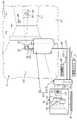
- the image projection system 100includes a control system 10 and a projector 30 controlled by the control system 10.
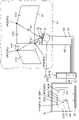
- the projector 30is installed at the installation position P4 in the real space A1, and at least the projection direction can be changed.
- the projector 30uses the image content D1 to irradiate the projection surface P1 of the projection surface A11 with light, for example, by irradiating the projection surface A11 such as a wall surface, a floor surface, or a ceiling surface existing in the real space A1.
- a third image Im3 (projected image) including the two objects Ob2is projected.
- the projector 30places the second object Ob2 corresponding to the first object Ob1 in the real space corresponding to the display position of the first object Ob1 in the virtual space A2 based on the second image Im2. It projects to the projection position P1 in A1.
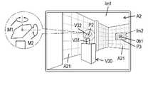
- the image content D1is data representing a second image Im2 (virtual image) including the first object Ob1 (see FIG. 3C) displayed at the display position P3 of the virtual space A2.
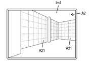
- the second image Im2is an image obtained by rendering the first image Im1 displayed in the virtual space A2 in a predetermined rendering area Ra1 with the virtual installation position P2 in the virtual space A2 corresponding to the installation position P4 as a viewpoint.
- the first image Im1is an image displayed in the virtual space A2 corresponding to the real space A1 and is an image including the first object Ob1.
- the image content D1 referred to in the present disclosureis the content of information (data) forming an image created based on the second image Im2, and is information (data) forming the third image Im3 projected by the projector 30.
- the third image Im3may be subjected to processing such as trimming, brightness adjustment, or contrast adjustment with respect to the image content D1.
- the control system 10mainly comprises a computer system having one or more processors and one or more memories.
- the installation information acquisition method and the image adjustment method according to the present embodimentare used on the computer system (control system 10). That is, the installation information acquisition method and the image adjustment method can also be embodied in the program.
- the program according to the present embodimentis a program for causing one or more processors to execute the installation information acquisition method and the image adjustment method according to the present embodiment.
- Installation information acquisition methodAs shown in FIG. 1, the installation information acquisition method in the image projection system 100 obtains installation information regarding the installation state of the projector 30 that projects the image content D1 at the projection position P1 of the real space A1. How to get it.
- the size, shape, and orientation of the third image Im3change depending on the installation position and direction of the projector 30 with respect to the projection position P1. Therefore, for example, even when the third image Im3 is projected on the front or left and right wall surfaces, the floor surface, or the ceiling surface, the second object Ob2 in the third image Im3 is projected with a constant size, shape, and orientation. It is necessary to determine the size, shape, and orientation of the first object Ob1 in the image content D1 according to the relative positional relationship between the projector 30 and the projection position P1. As an example, when the projection distance from the projector 30 to the projection position P1 becomes long with the slow ratio constant, the third image Im3 becomes large.
- the size of the first object Ob1 in the image content D1is reduced, or the slow ratio is changed by the zoom lens. It is necessary to reduce the size of the third image Im3 itself. Further, when the projection position P1 moves from the front wall surface to the left or right wall surface, for example, the projection direction changes and the direction of the second object Ob2 rotates. Even in this case, in order to keep the size, shape, and orientation of the second object Ob2 in the third image Im3 constant, it is necessary to increase the size of the first object Ob1 and rotate the orientation.
- the installation information regarding the installation state of the projector 30includes information regarding at least one of the installation position of the projector 30 relative to the projection position P1 in the real space A1 and the installation direction of the projector 30.
- the projection position P1changes at any time in the real space A1
- the relative positional relationship between the projector 30 and the projection position P1changes, so the positional relationship between the two, that is, the installation state of the projector 30 is taken into consideration. It takes a lot of time and effort to generate the image content D1.
- the image content D1 projected by the projector 30is generated by the following content generation method.
- a virtual space A2(see FIGS. 3A to 3C) corresponding to the real space A1 is created on the computer.
- the virtual installation position P2 corresponding to the installation position of the projector 30 in the real space A1 and the display position P3 corresponding to the projection position P1 of the real space A1are reproduced.
- the second image Im2(virtual image) including the first object Ob1 viewed from the virtual installation position P2 in a state where the first object Ob1 is projected (displayed) on the display position P3 in the virtual space A2. Is generated as the image content D1.
- the second image Im2 including the first object Ob1 viewed from the virtual installation position P2is generated as the image content D1 in the state where the first object Ob1 is displayed at the display position P3.
- the first object Ob1can be virtually displayed in any size, shape, and orientation at any display position P3.
- the third image Im3 based on the image content D1is projected onto the projection position P1 by the projector 30 installed at the actual installation position P4 corresponding to the virtual installation position P2, the projected second object Ob2 is displayed. It substantially matches the first object Ob1 virtually displayed at the position P3. Therefore, if the projector 30 is installed in the installed state as set, the projector 30 projects the image content D1 created by the above content generation method to project the desired second object Ob2 at the projection position P1. It will be possible to do.
- the projection positionwhen the above image content D1 is projected by the projector 30, if the installation position and the installation direction with respect to the projection position P1 are significantly deviated from the installation position and the installation direction assumed at the time of creating the image content D1, the projection position.
- the second object Ob2may not be projected correctly on P1.
- “the second object Ob2 is not projected correctly”is projected to the projection position P1 with respect to the size, shape, and orientation of the first object Ob1 displayed at the display position P3 in the virtual space A2.
- a state in which at least one of the size, shape, and orientation of the second object Ob2does not match.
- the projection position P1 of the projector 30moves from one of the front or left and right wall surfaces, the floor surface, or the ceiling surface to another surface in the real space A1, the image is projected to a position straddling the surface. There is a possibility that it will not be projected correctly due to deformation.
- the installation information regarding the installation state of the projector 30is acquired.
- the projector 30is installed at the installation position P4 in the real space A1, and the projection direction can be changed with respect to the reference direction.
- the projector 30projects the third image Im3 based on the second image Im2 onto the projection position P1 in the real space A1.
- the second image Im2is an image when the image projected on the display position P3 of the virtual space A2 corresponding to the real space A1 is viewed from the virtual installation position P2 in the virtual space A2 corresponding to the installation position P4.
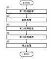
- This installation information acquisition methodincludes a first acquisition process, a projection process, a second acquisition process, and a third acquisition process.
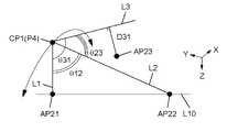
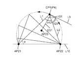
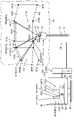
- position information regarding the positions of three or more first adjustment points AP1 (see FIG. 14) in the virtual space A2is acquired.
- the projector 30projects an index image on the real space A1.
- angle information regarding the angle of the projection direction of the projector 30 with respect to the reference direction in a state where the positions of the index images coincide with each of the three or more second adjustment points AP2 (see FIG. 15)is acquired.
- the second adjustment point AP2 having three or more pointscorresponds to the first adjustment point AP1 having three or more points in the virtual space A2.
- the installation information regarding the installation state of the projector 30is acquired based on the above position information and the above angle information.
- the installation information regarding the installation state of the projector 30includes information regarding at least one of the installation position and the installation direction of the projector 30 in the real space A1.
- the reference directionis a reference direction when the projector 30 whose projection direction can be changed projects an image.
- the projection direction in which both the pan angle and the tilt angle are zerois the reference direction.
- the imageis projected at a position in front of the projector 30 as an example.
- the state in which the projector 30 is installed in the installation position and the installation direction assumed when creating the image content D1may both be referred to as a reference state.
- first adjustment points AP1 having three or more pointsare points set in the virtual space A2 in order to estimate the installation state of the projector 30 in the real space A1.
- the second adjustment point AP2 having three or more pointsis a point in the real space A1 corresponding to the first adjustment point AP1 having three or more points set in the virtual space A2.
- the second acquisition processacquires angle information in a state where the position of the index image, that is, the projection direction of the projector 30 coincides with each of the three or more second adjustment points AP2.
- the positions of the second adjustment points AP2 having three or more pointscorrespond to the positions of the first adjustment points AP1 having three or more points in the virtual space A2. Therefore, by the third acquisition process, the installation information of the projector 30 can be acquired based on the position information and the angle information of the first adjustment point AP1 of three or more points, and the installation state of the projector 30 is the installation at the virtual installation position P2. It is possible to grasp whether or not it is out of the state.
- the projection direction of the projector 30 or the virtual imageis based on the installation information acquired in the third acquisition process.
- the projected imagecan be displayed more correctly by performing processing such as correcting the image data of. Therefore, it is not necessary to strictly install the projector 30 in the real space A1 according to the installation state assumed when generating the virtual image, and there is an advantage that the degree of freedom of the installation state of the projector 30 in the real space A1 is improved. There is.
- the installation information acquisition method according to the present embodimentis executed by the installation information acquisition system 15 as shown in FIG. 2 as an example.
- the installation information acquisition system 15is an aspect for embodying the above-mentioned installation information acquisition method.
- the installation information acquisition system 15 according to the present embodimentacquires installation information regarding the installation state of the projector 30.
- the projector 30is installed at the installation position P4 in the real space A1, and the projection direction can be changed with respect to the reference direction.
- the projector 30projects a projected image based on a virtual image at a projection position P1 in the real space A1.
- the virtual imageis an image when the image projected on the display position P3 of the virtual space A2 corresponding to the real space A1 is viewed from the virtual installation position P2 in the virtual space A2 corresponding to the installation position P4.
- the installation information acquisition system 15includes a first acquisition unit 151, a projection processing unit 154, a second acquisition unit 152, and a third acquisition unit 153.
- the first acquisition unit 151acquires position information regarding the positions of three or more first adjustment points AP1 in the virtual space A2.
- the projection processing unit 154causes the projector 30 to project an index image onto the real space A1.
- the second acquisition unit 152acquires angle information regarding the angle of the projection direction of the projector 30 with respect to the reference direction in a state where the positions of the index images coincide with each of the three or more second adjustment points AP2.
- the second adjustment point AP2 having three or more pointscorresponds to the first adjustment point AP1 having three or more points in the virtual space A2.
- the third acquisition unit 153acquires installation information regarding the installation state of the projector 30 based on the above position information and the above angle information.
- the number of the first adjustment point AP1 from which the first acquisition unit 151 acquires the position information and the number of the second adjustment point AP2 corresponding to the first adjustment point AP1are three, respectively, as an example.
- the number of the first adjustment point AP1 and the second adjustment point AP2is not limited to three points, and may be four or more points.
- the image adjustment method in the image projection system according to the present embodimentis a method of adjusting the size of the image projected by the projector 30 at the projection position P1 of the real space A1.
- the image projection system 100can, for example, project a second object Ob2 corresponding to one or more first objects Ob1 of the second image Im2 onto the real space A1.
- the control system 10accepts the setting of the rendering area set as the first image Im1 to the second image Im2.
- Image content D1 in which the pixel value (brightness value) of the portion other than the second object Ob2 in the rendering area, that is, the portion corresponding to the background is 0 (black)is created, and the third image based on this image content D1 is created.
- Im3is projected onto the real space A1 by the projector 30.
- the size of the second object Ob2 projected on the real space A1is determined according to the size of the first object Ob1 with respect to the size of the rendering area for rendering the second image Im2 with the virtual installation position P2 as the viewpoint. Will be done.
- the size of the second object Ob2is the viewing angle when the second image Im2 is taken by the virtual camera V30 installed at the virtual installation position P2 when the size of the first object Ob1 in the virtual space A2 is constant. Determined according to (Field of View).
- the control system 10When displaying the portion corresponding to the background in the third image Im3 in addition to the second object Ob2, the control system 10 accepts the setting of the rendering area set as the first image Im1 to the second image Im2, and the relevant The image content D1 is created by appropriately setting the pixel values of the portion of the rendering area other than the second object Ob2, that is, the portion corresponding to the background.
- the background settingmay be determined by selecting the content for the background in addition to the setting of the pixel value of the background.
- the backgroundis determined in the first image Im1, for example, as an image that does not move even after a lapse of time.
- the first object Ob1is determined in the first image Im1, for example, as an image that moves with the passage of time.
- the usercan determine one or more first objects to be projected onto the real space A1 by controlling the control system 10 using the input device 50, and corresponds to the first object Ob1 determined by the user.
- the second object Ob2can be projected onto the real space A1.
- the position of the object in the imagemay deviate from the desired projection position.
- a second object Ob22for example, a building
- a second object Ob23for example, a building
- the control system 10first presents the first object Ob12 corresponding to the second object Ob22 in a fixed position on the virtual space A2.
- Generate a first image Im1such that the first object Ob13 corresponding to the second object Ob23 is at the starting point on the left side.
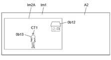
- the control system 10generates a second image Im2A in which the first image Im1 is rendered in a predetermined rendering area with the virtual installation position P2 as a viewpoint, and the third image Im3A based on the second image Im2A is generated in the real space by the projector 30. Project to A1.
- the control system 10generates the second image Im2A so that the moving first object Ob13 is located at the image center CT1.
- the control system 10creates an image Im1 (moving image) in which the first object Ob12 exists at a fixed position on the virtual space A2 and the first object Ob13 gradually moves to the right.
- the second image Im2A(moving image) is rendered so that the first object Ob13 is located at the center CT1.
- the control system 10projects the third image Im3A (moving image) based on the second image Im2A onto the real space A1 by the projector 30.
- the second object Ob22exists at a fixed position, and a moving image in which the second object Ob23 moves from left to right is projected.
- the control system 10changes the projection direction of the projector 30 in accordance with the movement of the first object Ob13 in the virtual space A2, that is, the movement of the image center CT1 of the second image Im2A, thereby changing the projection direction of the third image Im3A. Change the projection position of.
- the second object Ob23 projected on the real space A1moves.
- the second image Im2Ais formed so that the first object Ob13 exists in the image center CT1
- the first object Ob12 existing at a fixed positionis the second image Im2A.
- the second object Ob22moves at a fixed position in the real space A1.
- the image center CT1 of the second image Im2Athat is, the image center of the third image Im3A projected on the real space A1
- the image center CT1 of the second image Im2Athat is, the image center of the third image Im3A projected on the real space A1
- the second object Ob22does not appear to move in the real space A1.
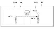
- the image size of the third image Im3A projected on the real space A1 by the projector 30 and the size of the rendering area Ra1 of the second image Im2A created in the virtual space A2do not match. Since the moving first object Ob13 exists in the image center CT1 of the second image Im2A, the display position in the virtual space A2 and the projection position in the real space A1 are the same positions. On the other hand, since the first object Ob12 existing at a fixed position is displayed at a position different from the image center CT1 of the second image Im2A, the size of the rendering area Ra1 of the second image Im2A and the image size of the third image Im3A.
- the second object Ob22 corresponding to the first object Ob12is projected at a position different from the projection position corresponding to the display position in the virtual space A2 in the real space A1. Therefore, if the projection direction of the projector 30 is changed according to the movement of the first object Ob13 (second object Ob23), the second object Ob22, which should be projected at a fixed position, may appear to be moving. ..
- the fact that the size of the rendering area Ra1 of the second image Im2A and the image size of the third image Im3A do not matchmeans that the relative sizes do not match.
- the size of the result of converting the size of the rendering area Ra1 of the second image Im2A on the scale of the virtual space A2 into the scale of the real space A1 and the image size of the third image Im3A projected on the real space A1match. It means that it is not.
- FIG. 5Bshows an example of the third image Im3A projected on the real space A1.
- the image size of the third image Im3Ais larger than the size of the rendering area Ra1 of the second image Im2A (the size converted to the scale of the real space A1), it should be projected at a fixed position.
- the second object Ob2is projected at a position (position shown by a solid line) different from the projection position (position shown by the dotted line) corresponding to the display position in the virtual space A2.
- FIG. 6Awhen the second image Im2B is rendered so that the first object Ob13 moves from left to right, it should be projected at a fixed position in the real space A1 as shown in FIG. 6B.
- the second object Ob22was projected so as to move from right to left.
- the first image generation step, the first adjustment image generation step, the first adjustment image projection step, the second adjustment image generation step, and the second adjustment image projection stepare included.
- the positional deviation between the projected position of the image projected on the real space A1 by the projector 30 and the position corresponding to the display position in the virtual space A2is reduced.
- the image adjustment method of the present embodimentwill be described with reference to FIGS. 19 to 22.
- the diamond-shaped first object Ob5is displayed on the first image Im1
- the diamond-shaped second object Ob6 corresponding to the first object Ob1is projected on the real space A1.
- the shapes and sizes of the first object Ob1 and the second object Ob6can be changed as appropriate.
- the second position P6position shown in FIG. 19
- the first position P5position of the second object Ob6 shown by the dotted line in FIG. 20
- the first image Im1 in which the first object Ob5 is displayedis generated.
- the first object Ob5is positioned in the first direction (for example, the right direction which is one of the pan directions) with respect to the image center CT1.
- Image Im21is rendered.
- the projector 30makes the second object Ob6 (specifically, the third image Im31 including the second object Ob6) in real space based on the first adjusted image Im21. It projects to the first projection position PT1 in A1. Since the size of the rendering area Ra1 of the first adjusted image Im21 and the image size of the third image Im31 do not match, the second object Ob6 is the first corresponding to the second position P6 in the virtual space A2. It is projected at a position deviated from the position P5. In the examples of FIGS. 19 and 20, the image of the third image Im31 projected onto the real space A1 is compared with the size of the rendering area Ra1 of the first adjusted image Im21 (the size when converted to the scale of the real space A1).
- the second object Ob6is projected to the right of the first position P5. That is, the distance from the image center CT2 of the third image Im31 to the actual projection position of the second object Ob6 is longer than the distance from the image center CT2 to the first position P5.
- the second imageis used.
- the object Ob6is projected on the left side of the first position P5 corresponding to the display position in the virtual space A2. That is, the distance from the image center CT2 of the third image Im31 to the actual projection position of the second object Ob6 is shorter than the distance from the image center CT2 to the first position P5.
- the first object Ob5is located in the second direction (for example, the left direction) opposite to the first direction with respect to the image center CT1 as the first image Im1 to the second image Im2.
- the second adjusted image Im22(see FIG. 21) is rendered.
- the projector 30makes the second object Ob6 (specifically, the third image Im32 including the second object Ob6) based on the second adjusted image Im22 in the real space A1. It is projected to the second projection position PT2 (the position shown by the solid line in FIG. 22).
- the image size of the third image Im32is larger than the size of the rendering area Ra1 of the second adjusted image Im22 (the size when converted to the scale of the real space A1), so that the second image is second.
- the object Ob6will be projected to the left of the first position P5.
- the second object Ob6is in the first position. It will be projected on the right side of P5.
- the projection size of the second object Ob6 in the real space A1is adjusted so as to reduce the positional deviation between the first projection position PT1 and the second projection position PT2.
- the method of adjusting the projection size of the second object Ob6 in the real space A1includes at least one of the zoom adjustment of the projector 30 and the size adjustment of the rendering area Ra1.
- the image size of the third image Im31is larger than the size of the rendering area Ra1 of the first adjusted image Im21 (the size when converted to the scale of the real space A1).
- the zoom of the projector 30may be adjusted so as to reduce the projection size of the projected second object Ob6.
- the zoom adjustmentis performed so that the image size (angle of view) of the third image Im32 is reduced to the size shown by the dotted line, the positional deviation between the first projection position PT1 and the second projection position PT2 is reduced. can do.
- the projection size of the second object Ob6is adjusted by adjusting the size of the rendering area Ra1 of the second image Im2 rendered from the first image Im1 in the adjustment step. Then, the projection position of the second object Ob6 may be adjusted accordingly. Further, in the case of the projector 30 capable of zoom adjustment, the projection size of the second object Ob6 may be adjusted by adjusting the zoom of the projector 30 in the adjustment step, or the rendering area for rendering the second image Im2. The projection size of the second object Ob6 may be adjusted by adjusting the size of Ra1, or both the zoom adjustment of the projector 30 and the size adjustment of the rendering area Ra1 of the second image Im2 may be performed.
- the projection position of the second object Ob6can be adjusted, thereby the first projection positions PT1 and the second.
- the positional deviation from the projection position PT2can be reduced.
- the third image Im3BIf the zoom adjustment is performed so that the image size (angle of view) is reduced to the size shown by the dotted line, the positional deviation between the first projection position PT1 and the second projection position PT2 can be reduced.
- the size adjustment of the projection size of the second object Ob6 in the real space A1is not limited to the zoom adjustment by the projector 30, but the size adjustment of the rendering area Ra1 of the second image Im2 is also possible. For example, as shown in FIG.
- the projection size of the second object Ob6 in the real space A1is reduced by increasing the size of the rendering area when rendering the second image Im2B to the size shown by the dotted line. This makes it possible to reduce the positional deviation between the first projection position PT1 and the second projection position PT2.
- the image adjustment method according to the present embodimentis executed by the control system 10 as shown in FIG. 2 as an example.
- the control system 10is an aspect for embodying the above-mentioned image adjustment method.
- the control system 10controls the projector 30 of the image projection system 100.
- the projector 30is installed at the installation position P4 in the real space A1, and at least the projection direction can be changed.
- the projector 30sets the second object Ob6 corresponding to the first object Ob5 to the real space A1 corresponding to the display position of the first object Ob5 in the virtual space A2 based on the second image Im2.
- the second image Im2is an image obtained by rendering the first image Im1 including the first object Ob5 in a predetermined rendering area Ra1 with the virtual installation position P2 in the virtual space A2 corresponding to the installation position P4 as a viewpoint.
- the "image” referred to in the present disclosureincludes a moving image (moving image) and a still image (still image). Further, the "moving image” includes an image composed of a plurality of still images obtained by time-lapse photography or the like. Further, the "image” includes a monochrome image and a color image. As an example in the present embodiment, the "image” is an image (that is, a moving image) that changes with the passage of time, and is a full-color image. That is, as an example in the present embodiment, the third image Im3 projected by the projector 30 is a full-color moving image, and the image content D1 which is the content of the information forming the third image Im3 is also the data of the full-color moving image. Is.
- the "real space” referred to in the present disclosuremeans a real space, that is, an existing space, and includes an internal space (indoor space) of an existing facility (building) and an outdoor space.
- the facilities referred to hereinclude, for example, non-residential facilities such as commercial facilities, theme parks, office buildings, schools, welfare facilities, hospitals and factories, and facilities such as apartment houses and detached houses.
- Non-residential facilitiesinclude theaters, movie theaters, public halls, amusement parks, complex facilities, restaurants, department stores, hotels, inns, kindergartens, libraries, museums, museums, underground streets, stations and airports.
- the "facility" as used in the present disclosureincludes not only buildings (buildings) but also outdoor facilities such as ballparks, parking lots, grounds and parks.
- the surface (wall surface, floor surface, ceiling surface, etc.) of the facility structuresuch as a wall, floor, or ceiling is a projection surface A11 for projecting the third image Im3.
- the surface of equipment (equipment, furniture, equipment and equipment) installed inside the facilitysuch as doors, partitions, shelves, desks, chairs, home appliances, whiteboards or screens, is the third image. It can be a projection plane A11 for projecting Im3.
- the outer wall, roof or pillar of a facility consisting of a building, as well as the surface of an object such as the ground, rocks or treescan be the projection plane A11 for projecting the third image Im3.
- the real space A1is an indoor space (indoor space) of a room of a non-residential facility such as a commercial facility, and the wall surface, floor surface, ceiling surface, etc. of the room is the projection surface A11. The case where it becomes will be described.
- the "virtual space” referred to in the present disclosuremeans a virtual space that does not exist, does not actually exist in the real space (real space A1), and is not accompanied by an entity. Therefore, the virtual space A2 is composed of data that can be processed by, for example, one or more processors, and is visually recognized by the user via a user interface such as a display device as a virtual space reproduced by a computer system.
- the virtual space A2is a space corresponding to the real space A1 on which the third image Im3 is projected.
- the virtual space A2is a space that imitates the real space A1 in which the projector 30 is installed, and for example, a virtual space in which structures such as walls, floors, and ceilings are laid out in the same manner as the real space A1. It is a space. Therefore, the virtual space A2 includes a virtual projection surface A21 (see FIGS. 3A to 3C) corresponding to the projection surface A11 on which the third image Im3 is projected in the real space A1. However, the virtual space A2 may at least imitate the real space A1 with respect to the layout of the surface of the structure including the projection surface A11, and the inside and the back side of the structure, the surface state of the structure, the lighting fixture, and the like.
- the virtual space A2is a three-dimensional space represented by an XYZ Cartesian coordinate system having three axes orthogonal to each other of the X-axis, the Y-axis, and the Z-axis.
- the "position" referred to in the present disclosuremay have a certain size and shape, or may be a "point" having no size. Therefore, for example, in the case of the projection position P1, in the real space A1, it may be defined by a region having a certain size and shape, or it may be defined by a "point” on the coordinates having no size. You may.
- the projection position P1is composed of a region having a certain size (area) on the projection surface A11.
- the display position P3 (see FIG. 1) corresponding to the projection position P1is a region having a certain size (area) in the virtual space A2.
- the virtual installation position P2(see FIGS. 1 and 3C) is a “point” having no size.
- the installation position P4(see FIG. 1), which will be described later, represents a position where the projector 30 is installed in the real space A1 and is a “point” having no size. That is, the installation position P4 is a position of one point (for example, the center point of the mirror portion 32 described later) defined with respect to the projector 30.
- the virtual installation position P2 and the display position P3 in the virtual space A2are only defined to exist virtually in the virtual space A2, do not actually exist in the real space (real space A1), but actually exist. Not accompanied.
- the "object” referred to in the present disclosureconsists of data that can be processed by one or more processors, does not actually exist in the real space (real space), and is not accompanied by an entity.
- the first objects Ob1, Ob5, Ob11 to Ob13 and the second objects Ob2, Ob6, Ob22, Ob23are virtual models representing some objects (including living things), symbols, symbols, numbers, letters, etc. It may be either a dimensional model or a three-dimensional model.
- the first object Ob1 and the second object Ob2 shown in FIGS. 1 and 4are two-dimensional models imitating a “butterfly”.
- 5B and 6Bare two-dimensional models imitating a "house” set as a background.
- the first object Ob13 shown in FIGS. 5A, 6A and 7 and the second object Ob23 shown in FIGS. 5B and 6Bare two-dimensional models imitating a “human”.
- the control system 10includes an installation information acquisition system 15 that acquires installation information of the projector 30, and generates image data to be projected by the projector 30.
- the control system 10constitutes an image projection system 100 together with a projector 30 that projects the generated image content D1. That is, the image projection system 100 includes a control system 10 including an installation information acquisition system 15 and a projector 30.
- the image projection system 100it is possible to perform all the processing necessary for projecting the third image Im3 on the projection position P1 of the real space A1 from the generation of the image content D1 to the projection of the generated image content D1. be.
- the control system 10mainly includes a computer system having one or more processors and one or more memories.
- the control system 10is realized by one information terminal 1 including a personal computer.
- Dedicated application softwareprogram
- the information terminal 1functions as a control system 10, and an installation information acquisition method and an image.
- the adjustment methodis embodied.
- control system 10is connected to the display device 40 and the input device 50. Then, the control system 10 displays a screen on the display device 40, presents information to the user, and accepts the user's operation on the input device 50. For example, in the installation information acquisition method according to the present embodiment, it is possible to perform an operation such as inputting the position information of the three first adjustment points AP1 on the graphical user interface (GUI: Graphical User Interface) of the computer system. In the image adjustment method, it becomes possible to perform an operation or the like instructing the execution of the first adjustment image projection step, the second adjustment image projection step, or the like on the GUI.
- GUIGraphical User Interface
- the control system 10is configured to be able to communicate with the projector 30.
- the term "communicable” as used in the present disclosuremeans that information can be exchanged directly or indirectly via a network, a repeater, or the like by an appropriate communication method of wired communication or wireless communication. That is, the control system 10 and the projector 30 can exchange information with each other.
- the control system 10can transmit the index image, the first adjusted image Im21, the second adjusted image Im22, the control information D2 for projecting those images, and the like to the projector 30.
- the image projection system 100can transmit the image data of the index image, the first adjusted image Im21, and the second adjusted image Im22 to the projector 30 and project these images on the projector 30. Further, the image content D1 and the control information D2 can be transmitted from the control system 10 to the projector 30. As a result, the image projection system 100 can transmit the image content D1 generated by the control system 10 to the projector 30 and project the image content D1 on the projector 30.
- the control system 10 and the projector 30are connected by wire with a video cable 101, a control cable 102, and a communication cable 103.
- the video cable 101conforms to a communication standard such as HDMI (registered trademark), and is used for transmitting the image content D1 from the control system 10 to the projector 30.
- the control cable 102conforms to a communication standard such as a LAN (Local Area Network), and is used for transmitting control information D2 from the control system 10 to the projector 30.
- the communication cable 103conforms to a communication standard such as LAN, and is used for exchanging various information between the control system 10 and the projector 30.
- the control cable 102 and the communication cable 103may be shared by one LAN cable, or may be used separately for controlling the mirror unit 32 and for controlling the main body of the projector 30, which will be described later. ..
- the projector 30projects the image content D1 generated by the control system 10 on the projection position P1 of the real space A1.
- the projector 30is installed at the installation position P4 in the real space A1.
- the installation position P4is a position determined with respect to the projector 30 as described above, and is, for example, a position of the center point of the mirror portion 32 described later. That is, the projector 30 is installed in the real space A1 so that the center point of the mirror portion 32 is located at the installation position P4.
- the projector 30irradiates light toward the projection surface A11 such as a wall surface, a floor surface, or a ceiling surface existing in the real space A1, so that the second object is placed on the projection position P1 of the projection surface A11.
- the third image Im3 including Ob2is projected.
- the projector 30projects the image content D1 transmitted (delivered) from the control system 10 in real time.
- the control system 10has a function as a video reproduction device that reproduces the image content D1 and outputs (transmits) a video signal. That is, in the image projection system 100, the control system 10 generates and reproduces the image content D1, and the projector 30 projects the image content D1.
- the display device 40is realized by, for example, a liquid crystal display, an organic EL (Electro Luminescence) display, or the like.
- the display device 40receives a video signal from the control system 10 and displays a "screen" such as an input screen, thereby presenting the user with an installation information acquisition method and an image adjustment method.
- the input device 50is realized by, for example, a pointing device such as a keyboard and a mouse, a mechanical switch, a gesture sensor, or a voice input device.
- the input device 50receives the user's operation (including voice operation) in the installation information acquisition method and the image adjustment method, and outputs an operation signal corresponding to the user's operation to the control system 10.
- At least one of the display device 40 and the input device 50may be included in the components of the control system 10.
- the control system 10may include at least one of the display device 40 and the input device 50.
- the display device 40 and the input device 50may be realized by a touch panel display, and in this case, the display device 40 and the input device 50 are integrated.
- the projector 30is a floor-standing type that is used by placing it on the floor (including the ground). Therefore, the position (installation position P4) and the installation direction of the projector 30 in the horizontal plane can be arbitrarily set depending on the position where the projector 30 is placed and the orientation of the projector 30 on the floor.
- the projector 30is placed on the floor, but the projector 30 is not limited to the floor-standing type, and may be fixed to an arm provided on a wall surface, a floor surface, or a ceiling surface, for example. It may be hung from the ceiling surface with a wire or the like.
- the projector 30has, for example, an adjuster function on the legs supporting the main body, and the height in the vertical direction can also be adjusted by adjusting the height from the floor surface of the main body.
- the projector 30is installed at a position appropriately separated from any wall surface in the real space A1 consisting of the indoor space of the facility.
- the projector 30irradiates light toward the projection surface A11 such as a wall surface, a floor surface, or a ceiling surface existing around the projector 30, and thereby uses the image content D1 to project the projection position P1 of the projection surface A11.
- the third image Im3is projected onto the image.
- the projector 30is a movable projection system in which the projection position P1 is not fixed, but the projection position P1 in the real space A1 is variable. That is, the projection position P1 of the third image Im3 can move in the real space A1.
- the projector 30moves the projection position P1 by changing the irradiation direction of light (that is, the projection direction of the image).
- the projector 30 installed in front of the projection surface A11changes the irradiation direction of light from the left end to the right end of the projection surface A11, so that the projection position P1 moves to the right on the projection surface A11. Will be done.
- the projector 30is a moving mirror type projection system, and by moving the mirror unit 32 located on the optical path of the irradiated light, the irradiation direction of the light is changed to change the third image.
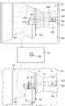
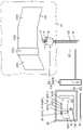
- the projection position P1 of Im3is moved. That is, as shown in FIGS. 1 and 2, the projector 30 has a projection unit 31, a mirror unit 32, and a drive unit 33.
- the projection unit 31emits light for projecting an image (third image Im3) on the real space A1 by using the image content D1.
- the mirror unit 32reflects the light emitted from the projection unit 31.
- the drive unit 33changes the projection direction of the image by driving the mirror unit 32 so as to change the direction of the mirror unit 32, and moves the projection position P1 of the image.
- the drive unit 33swings the mirror unit 32 to change the reflection direction of the light emitted from the projection unit 31 in the mirror unit 32, and the light from the projector 30 (mirror).
- the irradiation direction of the light reflected by the unit 32, that is, the projection direction of the imageis changed.
- the projection unit 31has, as an example, a cylindrical optical unit 311 projecting upward from the upper surface of the main body of the projector 30.
- the optical unit 311includes a lens system including a plurality of lens elements.
- the projector 30receives the control information D2 including the control instruction input from the control system 10
- the projector 30changes the zoom of the lens system according to the control instruction to project the image of the third image Im3 projected on the real space A1.
- Adjust the sizethat is, the projected size of the second object Ob2
- the image size of the third image Im3 projected on the real space A1that is, the projection size of the second object Ob2 is also adjusted by the user manually adjusting the zoom of the lens system. Can be done.
- the projection unit 31emits light upward from the opening on the upper surface of the optical unit 311 along the optical axis of the optical unit 311.
- the light emitted from the projection unit 31is light for projecting the third image Im3 including the second object Ob2, and when this light is applied to the projection surface A11, an image is formed on the projection surface A11. Then, the third image Im3 including the second object Ob2 is projected.
- the projection unit 31emits an image corresponding to the image content D1 as light.
- the optical axis of the light emitted from the projection unit 31is along the vertical direction and intersects the center of the surface (reflection surface) of the mirror unit 32.
- the mirror unit 32is a flat mirror having a polygonal (hexagonal) surface (reflection surface) and is held by the drive unit 33 so as to be swingable. Since the light from the projection unit 31 is incident from below at the center point of the surface of the mirror unit 32, the mirror unit 32 is basically held in a posture in which the surface is directed diagonally downward. .. As a result, the light emitted upward from the projection unit 31 is reflected laterally on the surface of the mirror unit 32 toward the projection surface A11 such as the wall surface, floor surface, or ceiling surface existing around the projector 30. Be irradiated.
- the projection surface A11such as the wall surface, floor surface, or ceiling surface existing around the projector 30. Be irradiated.
- the drive unit 33holds the mirror unit 32 so as to be swingable, and drives the mirror unit 32 so as to change the direction of the mirror unit 32.
- the drive unit 33is realized by, for example, an actuator including a motor or the like.
- the control information D2 transmitted from the control system 10 to the projector 30includes information used for controlling the drive unit 33, and includes information for moving the projection position P1 on which the image is projected in the real space A1. ..
- the drive unit 33has a "pan operation” of rotating around the vertical axis passing through the center point of the surface of the mirror unit 32 and a “tilt operation” of rotating the drive unit 33 around the horizontal axis passing through the center point of the surface of the mirror unit 32.
- Two types of operationsare possible: “operation” and “operation”.
- the pan operationthe direction of the normal at the center point of the surface of the mirror portion 32 changes along the horizontal direction (also referred to as the pan direction), and the azimuth of the mirror portion 32 changes.
- the tilt operationthe direction of the normal line at the center point of the surface of the mirror portion 32 changes along the vertical direction (also referred to as the tilt direction), and the elevation / depression angle of the mirror portion 32 changes.
- the drive unit 33can freely change the direction of the mirror unit 32 around the center point of the surface of the mirror unit 32 by combining the pan operation and the tilt operation. Therefore, the projection position P1 to which the light reflected by the mirror unit 32 is irradiated (that is, the image is projected) can be moved in the two-dimensional directions of up, down, left, and right on the projection surface A11 made of a wall surface, for example.
- control system 10including the installation information acquisition system 15 according to the present embodiment will be described.
- the control system 10includes a first image generation unit 11, a second image generation unit 12, a projection control unit 13, an adjustment unit 14, an installation information acquisition system 15, a correction processing unit 16, and a generation unit 18. It includes a control information generation unit 19, an input unit 20, an output unit 21, a communication unit 22, and a data storage unit 23.
- the installation information acquisition system 15includes a first acquisition unit 151, a second acquisition unit 152, a third acquisition unit 153, and a projection processing unit 154.
- control system 10mainly includes a computer system having one or more processors and one or more memories. Specifically, in the control system 10, functions other than the communication unit 22 and the data storage unit 23 are embodied by executing a program by one or more processors.
- the first object Ob5is displayed at the second position P6 (see FIG. 19) in the virtual space A2 corresponding to the first position P5 (see FIG. 20) in the real space A1.
- the second image generation unit 12renders the first image Im1 to the second image Im2.
- the projection control unit 13projects the second object Ob6 corresponding to the first object Ob5 on the projector 30 based on the second image Im2.
- the second image generation unit 12sets the first image Im1 to the second image Im2, and the first adjusted image Im21 (see FIG. 19) in which the first object Ob5 is located in the first direction (for example, to the right) with respect to the image center CT1. ) Is rendered. Further, in the second image generation unit 12, the first object Ob5 is located in the second direction (for example, the left direction) opposite to the first direction with respect to the image center CT1 as the first image Im1 to the second image Im2. 2 Render the adjusted image Im22 (see FIG. 21).
- the projection control unit 13performs the first projection process and the second projection process.
- the projector 30causes the second object Ob6 (see FIG. 20) to be projected onto the first projection position PT1 in the real space A1 based on the first adjustment image Im21.
- the projector 30projects the second object Ob6 (see FIG. 22) on the second projection position PT2 in the real space A1 based on the second adjustment image Im22.
- the adjusting unit 14adjusts the projection size of the second object Ob6 in the real space A1 so as to reduce the positional deviation between the first projection position PT1 and the second projection position PT2.
- the control system 10is connected to, for example, an input device 50 that receives an adjustment instruction input by the user, and the adjustment unit 14 performs the above adjustment step according to the adjustment instruction received by the input device 50.
- the adjustment unit 14may cause the projector 30 to execute the zoom adjustment by outputting the control instruction to execute the zoom adjustment to the projector 30 based on the adjustment instruction received by the input device 50.
- the adjustment unit 14may allow the user to manually adjust the zoom of the projector 30 by displaying, for example, the adjustment content of the zoom adjustment on the display device 40 based on the adjustment instruction received by the input device 50. ..
- the control system 10may be configured to execute a part or all of each step of the image adjustment method based on the operation instruction of the user received by the input device 50, or each step of the image adjustment method. It may be configured to automatically perform some or all of the above.
- the first acquisition unit 151acquires the position information regarding the positions of the three first adjustment points AP1 set in the virtual space A2. In the present embodiment, the first acquisition unit 151 acquires the position information from the input unit 20.
- the projection processing unit 154causes the projector 30 to project the index image onto the real space A1.
- the second acquisition unit 152provides angle information regarding the angle of the projection direction of the projector 30 with respect to the reference direction in a state where the positions of the index images coincide with each of the three second adjustment points AP2 in the real space A1.
- the three second adjustment points AP2 in the real space A1correspond to the three first adjustment points AP1 in the virtual space A2, respectively.
- the installation state of the projector 30deviates from the reference state, when the index image is projected on the second adjustment point AP2 by the projector 30, the position of the actually projected index image is the second adjustment point AP2. May deviate from the position of.
- the user of the image projection system 100directly moves the mirror unit 32 of the projector 30 by hand or moves the mirror unit 32 via the input device 50 to display the index image at the position of the second adjustment point AP2.
- the projection direction of the projector 30is moved by the angle required to match the index image with the position of the second adjustment point AP2.
- the drive unit 33 of the projector 30can detect an angle of the projection direction of the projector 30 with respect to a reference direction by a sensor or the like provided in an actuator such as a motor, and outputs angle information regarding this angle.
- the second acquisition unit 152acquires the angle information from the control amount.
- the second acquisition unit 152communicates with the projector 30 to obtain an angle regarding the angle of the projection direction of the projector 30 with respect to the reference direction in a state where the position of the index image coincides with each second adjustment point AP2. Information may be obtained.
- the third acquisition unit 153has position information regarding the positions of the first adjustment points AP1 at the three points in the virtual space A2 and angle information when the index images are projected onto the second adjustment points AP2 at the three points. Based on the above, the installation information of the projector 30 is acquired. Each of the three second adjustment points AP2 is set at a position corresponding to each of the three first adjustment points AP1 in the real space A1. Therefore, based on the position information and the angle information of the second adjustment point AP2 obtained from the position information of the first adjustment point AP1, the third acquisition unit 153 installs the projector 30 in the real space A1 regarding the installation position and the installation direction. Information (that is, installation information regarding the installation status) can be acquired.
- the correction processing unit 16performs correction processing for correcting the projection direction in which the image is projected by the projector 30 based on the angle information acquired by the second acquisition unit 152.
- the correction processing unit 16projects a projection direction (pan angle and tilt angle) on which the image is projected by the projector 30 based on the angle information regarding the projection direction when the image is projected onto the second adjustment point AP2 in the real space A1.
- the correction processing performed by the correction processing unit 16will be described in "(5.4) Modification Example 4".
- the generation unit 18executes a generation process for generating the image content D1.
- the second image Im2image content D1 is generated by rendering a predetermined rendering area Ra1 from the first image Im1 in which the first object Ob1 is displayed (arranged) at the display position P3 of the virtual space A2. do.
- the generation unit 18generates a virtual space A2 that imitates the real space A1, and installs it at the virtual installation position P2 in a state where the first object Ob1 is virtually displayed at the display position P3 of the virtual space A2.
- Image content D1 (second image Im2)is generated as an image obtained by capturing the display position P3 from the virtual camera V30 (see FIGS. 1 and 3C).
- the rendering area Ra1 when rendering the second image Im2corresponds to the area expected by the angle of view at which the virtual camera V30 captures the second image Im2.
- the virtual display of the first object Ob1 to the display position P3 in the virtual space A2is executed by the generation unit 18.
- the control information generation unit 19executes the control information generation process for generating the control information D2.
- the control information D2 of the projector 30 for moving the projection position P1 in the real space A1is generated in synchronization with the movement of the display position P3.
- the control information D2 generated by the control information generation unit 19is output from the output unit 21.
- the generation unit 18virtually installs the virtual camera V30 (see FIG. 3C) at the virtual installation position P2 in the virtual space A2. That is, the installation information acquisition method and the image adjustment method of the present embodiment further include an arrangement process of arranging the virtual camera V30 at the virtual installation position P2 on the display screen expressing the virtual space A2.
- the "virtual camera” referred to in the present disclosureis a concept for specifying the rendering area Ra1, is a virtual device that imitates the function of the camera, and is merely defined as virtually existing in the virtual space A2. , Does not actually exist in the real space (real space A1) and is not accompanied by an entity.
- the virtual camera V30imitates the function of a video camera capable of shooting a full-color moving image.
- the virtual installation position P2represents a position where the virtual camera V30 is installed in the virtual space A2, and is a “point” having no size like the installation position P4.
- the virtual installation position P2is a position corresponding to the installation position P4 of the real space A1 in the virtual space A2.
- the virtual installation position P2is a position defined with respect to the virtual camera V30, and as an example, is a position of the center point of the virtual mirror unit V32 described later. That is, the virtual camera V30 is virtually installed in the virtual space A2 so as to be located at the virtual installation position P2 which is the center point of the virtual mirror unit V32.
- the virtual camera V30has a function of photographing a subject existing in the field of view of the virtual camera V30 and outputting an image reflected in the field of view as an image (image signal) like a general camera. Therefore, as shown in FIG. 3C, when the display position P3 is photographed by the virtual camera V30 in a state where the first object Ob1 is virtually displayed in the display position P3 of the virtual space A2, a predetermined position P2 is used as a viewpoint.
- the second image Im2 in which the rendering area Ra1 is renderedis output from the virtual camera V30. That is, the second image Im2 output at this time is an image including the first object Ob1, and the rendering area Ra1 corresponds to the area expected by the angle of view of the virtual camera V30.
- the generation unit 18After defining such a virtual camera V30, the generation unit 18 generates the image content D1 by setting the second image Im2 captured by the virtual camera V30 as the image content D1. In other words, the generation unit 18 generates an image obtained by rendering the first image Im1 displayed (arranged) at the display position P3 in the predetermined rendering area Ra1 with the virtual installation position P2 as the viewpoint, as the second image Im2. do.
- the input unit 20receives inputs of various information and signals from the outside of the control system 10.
- the input unit 20receives at least an input of an operation signal from the input device 50.
- the control system 10can indirectly accept the user's operation (including voice operation) in the installation information acquisition method and the image adjustment method by the input device 50.
- the input unit 20may accept input of information and signals from the outside via the communication unit 22.
- the output unit 21outputs at least the image content D1 generated by the generation unit 18.
- the output unit 21also outputs the control information D2 generated by the control information generation unit 19. Further, the output unit 21 outputs a video signal for displaying the screen for executing, for example, the installation information acquisition method and the image adjustment method on the display device 40.
- the mode of output by the output unit 21includes, for example, display, communication (transmission), sound, printing (printout), recording (writing) on a non-temporary recording medium, and the like.
- the output unit 21outputs at least the image content D1 and the control information D2 by recording (writing) to the data storage unit 23, and communicates (transmits) to the projector 30 from the communication unit 22. And output by.
- the communication unit 22has a function of communicating with the projector 30.
- the communication unit 22is wiredly connected to the projector 30 by the video cable 101, the control cable 102, and the communication cable 103.
- the data storage unit 23stores the image content D1 and the control information D2 and the like. Further, the data storage unit 23 also stores the position information of the first adjustment point AP1 acquired by the first acquisition unit 151, the angle information acquired by the second acquisition unit 152, and the installation information acquired by the third acquisition unit 153. do. Further, the data storage unit 23 includes a first image generation unit 11, a second image generation unit 12, a projection control unit 13, a first acquisition unit 151, a second acquisition unit 152, a third acquisition unit 153, a generation unit 18, and The information required for the calculation in the control information generation unit 19 and the like is stored. The data storage unit 23 includes a rewritable non-volatile memory such as an EEPROM (Electrically Erasable Programmable Read-Only Memory).
- EEPROMElectrically Erasable Programmable Read-Only Memory
- the control system 10has a function of generating an image content D1 based on the second image Im2, a function of acquiring installation information, and a video reproduction device for reproducing the image content D1 and outputting (transmitting) a video signal. It has a function and a function of adjusting the projection size of the second object projected on the real space A1. However, the control system 10 does not simultaneously generate the image content D1, acquire the installation information, reproduce the image content D1 (output the video signal), and adjust the projection size of the second object. Suppose you want to do it in different situations.
- the control system 10has at least four modes as an operation mode: a generation mode, an installation information acquisition mode, an adjustment mode, and a projection mode.
- the generation modeis an operation mode for generating the image content D1
- the control system 10generates the image content D1 and stores the generated image content D1 in the data storage unit 23.
- Store (store)The installation information acquisition mode is an operation mode for acquiring installation information regarding the installation state of the projector 30.
- the installation information acquisition system 15causes the projector 30 to project an index image onto the real space A1.
- the installation information acquisition system 15is based on the angle information when the index image is aligned with the position of the second adjustment point AP2 and the position information of the first adjustment point AP1 (that is, the second adjustment point AP2), and the projector 30 Get the installation information of.
- the adjustment modethe difference between the size of the rendering area Ra1 of the second image Im2 in the virtual space A2 (the size when converted to the scale of the real space A1) and the image size of the third image Im3 in the real space A1
- the projection modeis an operation mode for projecting the image content D1, and if it is operating in the projection mode, the control system 10 reproduces the image content D1 stored in the data storage unit 23 to play an image.
- the signalis output (transmitted) to the projector 30.
- Switching of the operation modegeneration mode, installation information acquisition mode, adjustment mode, projection mode
- FIGS. 3A to 3Care explanatory views that visualize the virtual space A2 created by the control system 10 to generate the image content D1.
- FIG. 4is an explanatory diagram conceptually showing the flow of processing in which the image content D1 is generated by the virtual camera V30 in the virtual space A2 and the generated image content D1 is projected by the projector 30 in the real space A1. be.
- the generation unit 18When generating the image content D1, the generation unit 18 first forms a virtual space A2 corresponding to the real space A1 as shown in FIG. 3A.
- the generation unit 18is, for example, a structure constituting a space such as a wall, a floor, and a ceiling in the real space A1 and an article (for example, a clock 200, a home electric appliance such as a television, a decorative item such as a painting) arranged in the real space A1.
- the virtual space A2is formed based on the spatial information that specifies the layout. This spatial information may be stored in advance in, for example, the data storage unit 23, or may be acquired from an external server device or the like.
- the virtual space A2is a non-existent virtual space, which is a virtual space composed of data that can be processed by one or more processors and reproduced by a computer system.
- the surface of a structuresuch as a wall, a floor, and a ceiling and an article arranged in the real space A1 is a virtual projection corresponding to the projection surface A11 of the real space A1. It becomes the surface A21.
- the scale (scale) of the same length (dimension) as the real space A1is not required. Therefore, for example, in the case of a wall, the aspect ratio is the same in the real space A1 and the virtual space A2. However, the height dimension may be different between the real space A1 and the virtual space A2.
- the control system 10specifies the display position P3 as shown in FIG. 3B based on the display position information about the display position P3 corresponding to the projection position P1 in the real space A1.
- the display position informationis information used to specify the display position P3 in the virtual space A2, and indicates the position in the virtual space A2 in the virtual projection surface A21 composed of the surfaces of structures such as walls, floors, and ceilings. Information to identify.
- the display position informationmay be stored in advance in the data storage unit 23, for example, the input unit 20 may accept input by the user, or may be acquired from an external server device or the like.
- the generation unit 18acquires information about the first object Ob1 from, for example, the data storage unit 23 or the like in order to display the first object Ob1 as shown in FIG. 3B. Specifically, the generation unit 18 acquires data for displaying the first object Ob1 on the virtual projection surface A21 from the data storage unit 23 or the like on the software of the three-dimensional computer graphics. Then, the generation unit 18 arranges the first object Ob1 at the display position P3 in the virtual space A2. By arranging the first object Ob1 at the display position P3 set on the virtual projection plane A21 of the virtual space A2, the first object Ob1 is virtually displayed.
- the generation unit 18sets the virtual camera V30 as shown in FIG. 3C at the virtual installation position P2 corresponding to the installation position P4 based on the installation position P4 (design value) in which the projector 30 is installed in the real space A1. To place.
- the virtual camera V30is composed of a virtual device that imitates the projector 30. That is, the virtual camera V30 is composed of a movable camera system in which the field of view is not fixed but the field of view in the virtual space A2 is variable in accordance with the movable projector 30. That is, the virtual camera V30 changes the incident direction of the light and moves the field of view by moving the virtual mirror unit V32 located on the optical path of the incident light. That is, as shown in FIG. 3C, the virtual camera V30 has a virtual photographing unit V31 and a virtual mirror unit V32.
- the virtual photographing unit V31photographs a subject existing in the field of view and outputs an image reflected in the field of view as an image (image signal).
- the virtual mirror unit V32reflects the light coming from the surroundings toward the virtual photographing unit V31.
- the virtual camera V30moves the field of view of the virtual camera V30 by driving the virtual mirror unit V32 so as to change the direction of the virtual mirror unit V32.
- the virtual camera V30swings the virtual mirror unit V32 to change the direction of arrival of the light incident on the virtual photographing unit V31 in the virtual mirror unit V32, and to the virtual camera V30. Change the incident direction of the light.
- the virtual camera V30imitates the projector 30 with respect to the incident direction of the light of the virtual photographing unit V31, the shape of the virtual mirror unit V32, the operation of the virtual mirror unit V32, and the like.
- the optical axis of the light incident on the virtual photographing unit V31is along the vertical direction and intersects the center of the surface (reflection surface) of the virtual mirror unit V32 or the center of rotation.
- the virtual mirror unit V32can freely change its direction around the center point of the surface of the virtual mirror unit V32, for example, by combining the pan operation and the tilt operation. In FIG.
- the moving (rotating) direction of the virtual mirror unit V32 during the pan operationis indicated by the arrow M1
- the moving (rotating) direction of the virtual mirror unit V32 during the tilt operationis indicated by the arrow M2.
- the viewing angle (angle of view) of the virtual camera V30is the same as the angle of view of the projector 30.
- the generation unit 18takes a picture of the display position P3 with the virtual camera V30 in the virtual space A2 in a state where the first object Ob1 is virtually displayed in the display position P3 of the virtual space A2. do. That is, in the virtual space A2, the image when the first object Ob1 displayed at the display position P3 is taken by the virtual camera V30 at the virtual installation position P2 is generated by the virtual camera V30. ..
- the control system 10generates, as shown in FIG. 4, an image including the first object Ob1 seen from the virtual installation position P2 as the image content D1 by the virtual camera V30 defined by the generation unit 18. Can be done.
- the virtual camera V30virtually captures a subject existing in the field of view of the virtual camera V30, and outputs an image reflected in the field of view as an image (image signal). Therefore, strictly speaking, the image output from the virtual camera V30 is not an image actually taken, but a rendered image generated (rendered) by arithmetic processing. In any case, the image output from the virtual camera V30 at this time is an image including the first object Ob1 seen from the virtual installation position P2 when the first object Ob1 is displayed at the display position P3 of the virtual space A2. .. Therefore, the generation unit 18 generates the image content D1 by setting the image virtually taken by the virtual camera V30 as the image content D1.
- the display device 40is the second image Im2 rendered from the first image Im1.
- An example of a screen displaying an image input to the projector 30 as the image content D1 as a reference image Im2ris shown. The user can confirm the image content D1 input to the projector 30 by visually recognizing the reference image Im2r of the display device 40.
- FIG. 8shows a case where the circular first object Ob11 is displayed on the virtual projection surface A22 in front of the virtual camera V30 in the virtual space A2.
- the shooting range of the virtual camera V30is rectangular, the first object Ob11 included in the rendered second image Im2 is also circular.
- the circular first object Ob11is displayed on the virtual projection surface A23 intersecting the virtual projection surface A22 in front of the virtual camera V30, and the virtual projection surface A22 and the virtual projection surface A23 are straddled.
- the case where the projection area Ra1 is setis shown.
- the first object Ob11looks circular, but from the virtual camera V30, the first object Ob11 appears to be distorted into an ellipse, so that the first object included in the rendered second image Im2.
- Ob11also has an elliptical distorted shape.
- the circular first object Ob11is displayed on the virtual projection surface A23 as in FIG. 9, but the first object Ob11 is displayed at a position closer to the virtual camera V30 than in FIG.
- the first object Ob11 included in the rendered second image Im2is displayed larger than the example of FIG. 9, and is closer to the front position when viewed from the virtual camera V30, so that the shape of the first object Ob11 Has a shape close to a circle.
- the first object Ob11is displayed on the virtual projection surface A22 in front of the virtual camera V30, but the first object Ob11 is displayed at the end of the virtual projection surface A22, so that the rendering is performed.
- the area Ra1also includes a portion where nothing is displayed. Since the portion other than the first object Ob11 is displayed in black in the second image Im2, the circular first object Ob11 is correctly displayed in the rendered second image Im2.
- the second image Im2is formed as an image rendered in the predetermined rendering area Ra1 with the virtual installation position P2 of the virtual camera V30 as a viewpoint, the second object based on the second image Im2 is formed by the projector 30.
- the second object corresponding to the first object Ob11is correctly displayed in the real space A1.
- FIG. 12shows a case where the rendering area Ra1 when rendering the first object Ob11 displayed on the virtual projection surface A22 in front of the virtual camera V30 is larger than that of FIG. 9.
- the size of the first object Ob11is smaller than that in FIG. 9, so that the projection size of the second object corresponding to the first object Ob11 can be reduced.
- the rendering area Ra1is made smaller than that of FIG. 9, the size of the first object Ob11 is larger than that of FIG. 9 in the rendered second image Im2, so that it corresponds to the first object Ob11.
- the projection size of the second objectcan be increased.
- the generation unit 18continuously shoots the first object Ob1 with the virtual camera V30 while the generation process is continuing. Generate image content D1. That is, the virtual camera V30 in the virtual space A2 shoots the first object Ob1 displayed at the display position P3 so that the virtual camera V30 shoots a moving image, so that the generation unit 18 can generate the image content D1 composed of the moving image data. Generated. Therefore, when the first object Ob1 has a movement, that is, when the first object Ob1 is an animation or the like that deforms with the passage of time, the movement of the first object Ob1 is reflected in the image content D1. .. As an example, when the first object Ob1 of the "butterfly" as illustrated in FIG. 4 has a "movement” like flapping, the image content D1 becomes data of a moving image in which the "butterfly" flaps.
- the image content D1 generated in this waycan be projected onto the real space A1 by the projector 30 by being transmitted to the projector 30.
- the third image Im3 projected at this timeis displayed at the projection position P1 corresponding to the display position P3 in the virtual space A2 in the real space A1.
- the projected second object Ob2substantially coincides with the first object Ob1 virtually displayed at the display position P3. Therefore, in the real space A1, the first object Ob1 virtually displayed in the virtual space A2 is projected as the third image Im3 as if the virtual space A2 was copied.
- the processing when the image content D1 is actually projected by the projector 30will be described in detail in the column of “(4.4) Projection mode”.
- the image content D1is an image of the first object Ob1 excluding the background of the first object Ob1 in the virtual space A2. That is, the second image Im2 virtually captured by the virtual camera V30 may include the virtual projection surface A21 or the like as the background, but the generation unit 18 is the first from the second image Im2 captured by the virtual camera V30. Only the object Ob1 is extracted to generate the image content D1. That is, in the image content D1 shown in FIG. 4, the periphery of the first object Ob1 is transparent (a state in which no image data exists).
- the image content D1 generated by the generation unit 18becomes the image data of only the first object Ob1 excluding the background.
- the portion inside the display position P3 other than the first object Ob1that is, the portion corresponding to the background is the pixel value ( The display is black in which the luminance value) is 0. Since the projector 30 does not irradiate the black image with light, as a result, an image of only the first object Ob1 excluding the background is generated as the image content D1.
- the projector 30 that projects the generated image content D1is a movable projection system in which the projection position P1 in the real space A1 is variable, and the projection position P1 is , It is possible to move in the real space A1. Therefore, the display position P3 corresponding to the projection position P1 can also move in the virtual space A2 in the same manner as the projection position P1. In other words, when the projection position P1 is moved by the projector 30 that projects the image content D1, the display position P3 is moved when the image content D1 is generated. In this case, the first object Ob1 displayed at the display position P3 also moves in the virtual space A2.
- the generation unit 18continuously generates the image content D1 by continuously shooting the first object Ob1 with the virtual camera V30 while the generation process is continuing while following the first object Ob1 with the virtual camera V30. can do.
- control system 10executes the control information generation process for generating the control information D2 in the control information generation unit 19. That is, in the control information generation process, the control information D2 of the projector 30 for moving the projection position P1 in the real space A1 is generated in synchronization with the movement of the display position P3. In other words, in the control information generation process, the control information D2 is generated in synchronization with the movement of the first object Ob1 in the virtual space A2.
- the control system 10generates information used for controlling the virtual camera V30 when following the moving first object Ob1 in the virtual camera V30 as control information D2. Specifically, in the control information generation process, the information used by the generation unit 18 to swing the virtual mirror unit V32 is generated as the control information D2. In short, the parameters used for controlling the virtual mirror unit V32 of the virtual camera V30 in the virtual space A2 coincide with the control information D2 which is the parameter used for controlling the mirror unit 32 of the projector 30 in the real space A1.
- the control system 10outputs the control information D2 in addition to the output of the image content D1. That is, the control system 10 outputs the image content D1 and the control information D2 by recording (writing) the image content D1 and the control information D2 in the data storage unit 23 in the output unit 21. As a result, the image content D1 generated in the generation process is recorded (stored) in the data storage unit 23 at any time together with the control information D2 generated in the control information generation process. Then, after the output of the image content D1 (and the control information D2), the control system 10 ends the operation in the generation mode when, for example, the input unit 20 receives the operation signal of the end operation from the input device 50.
- FIGS. 13 to 17for the operation of the installation information acquisition system 15 according to the present embodiment in the installation information acquisition mode, that is, the installation information acquisition method according to the present embodiment. I will explain.
- the image content D1 generated by the control system 10is projected by the projector 30 at the projection position P1 in the real space A1. Therefore, as a preparation, it is necessary to install the projector 30 at the installation position P4 assumed at the time of generating the virtual image.
- the installation position P4is a position corresponding to the virtual installation position P2 of the virtual space A2 in which the virtual camera V30 is installed, and the user installs the projector 30 at this installation position P4.
- the userinstalls the projector 30 so that the reference direction (installation direction of the projector 30) of the projection direction in which the projector 30 projects an image faces a predetermined direction.
- the projector 30 installed at the installation position P4is wiredly connected to the control system 10 by the video cable 101, the control cable 102, and the communication cable 103.
- the installation information acquisition system 15acquires installation information regarding the installation state of the projector 30 installed in the real space A1 by executing the installation information acquisition method. Then, the control system 10 can more correctly project the second object Ob2 on the projection surface A11 by using the installation information acquired by the installation information acquisition system 15 and correcting the projection direction of the projector 30, for example. can.
- the installation information regarding the installation state of the projector 30 referred to hereincludes at least one of the installation position of the projector 30 relative to the projection position P1 in the real space A1 and the installation direction of the projector 30.
- the first acquisition unit 151acquires position information regarding the positions of the three first adjustment points AP1 (see FIG. 14) in the virtual space A2.
- the acquisition processis performed (step S1).
- the installation information acquisition system 15causes the display device 40 to display an input screen for the user to input the first adjustment point AP1 in the installation information acquisition mode.
- the virtual space A2 formed corresponding to the real space A1is displayed.
- the first acquisition unit 151receives the operation signal from the input device 50 by the input unit 20 based on the operation signal.
- the position information of the first adjustment point AP1 of the three pointsis acquired as coordinate information in the XYZ Cartesian coordinate system representing the virtual space A2, for example.
- the first adjustment points AP11, AP12, and AP13are referred to as the first adjustment points AP11, AP12, and AP13.
- the discontinuity of two facesmay include a state in which two adjacent faces are non-parallel, or a state in which there is a step between the two faces.
- the first adjustment point AP11is set at the upper end of the boundary line of the adjacent virtual projection planes A211 and A212.
- the first adjustment point AP12is set at the lower end of the boundary line between the adjacent virtual projection planes A212 and A213.
- the first adjustment point AP13is set at the upper end of the boundary line of the adjacent virtual projection planes A213 and A214.
- the projection processing unit 154causes the projector 30 to output the image data of the index image (for example, a circular index) from the communication unit 22, and the projector 30 outputs the index image.
- a projection process for projecting an imageis performed (step S2).
- the index imageis not limited to a circular index, and its shape can be changed as appropriate.
- the useradjusts the orientation (pan and tilt) of the mirror portion 32 of the projector 30 to obtain the index image as the second adjustment point in the real space corresponding to the first adjustment point AP1 (AP11 to AP13). It is projected onto AP2 (AP21 to AP23) (see FIG. 15).
- the useradjusts the direction of the mirror unit 32 to project the index image onto the second adjustment point AP21.
- the second acquisition unit 152causes the projector via the communication unit 22.
- the angle information with respect to the reference direction of the projection directionis acquired from 30.
- the second acquisition unit 152acquires the pan angle PA1 and the tilt angle TL1 with respect to the reference direction in the projection direction in a state where the index image is projected on the second adjustment point AP21 as angle information.
- the userwhen the user adjusts the direction of the mirror unit 32 and projects the index image onto the second adjustment point AP22, the user inputs that the index image is aligned with the second adjustment point AP22 using the input device 50.
- the second acquisition unit 152acquires the angle information in this state.
- the second acquisition unit 152acquires the pan angle PA2 and the tilt angle TL2 with respect to the reference direction in the projection direction in a state where the index image is projected on the second adjustment point AP22 as angle information.
- the second acquisition unit 152acquires the angle information in this state.
- the second acquisition unit 152acquires the pan angle PA3 and the tilt angle TL3 with respect to the reference direction in the projection direction in a state where the index image is projected on the second adjustment point AP23 as angle information.
- the second acquisition unit 152acquires the angle information in a state where the positions of the index images match each of the second adjustment points AP2 having three or more points (three points in the present embodiment) in the real space A1. (Step S3).
- the third acquisition unit 153performs a third acquisition process of acquiring installation information regarding the installation state of the projector 30 (step S4).
- the projectoris based on the position information regarding the positions of the first adjustment points AP1 at the three points in the virtual space A2 and the angle information when the index image is projected onto the second adjustment points AP2 at the three points. Acquire the installation information of 30.
- the third acquisition unit 153projects the projection direction DR1 in a state where the index image is projected onto the second adjustment point AP21 and the index image onto the second adjustment point AP22 based on the angle information obtained in the second acquisition process.
- the angle ⁇ 12 formed by the projection direction DR2 in the state of being causedis calculated.
- the third acquisition unit 153projects the projection direction DR2 in a state where the index image is projected onto the second adjustment point AP22 and the index image onto the second adjustment point AP23 based on the angle information obtained in the second acquisition process.
- the angle ⁇ 23 formed by the projection direction DR3 in the state of being causedis calculated.
- the third acquisition unit 153projects the projection direction DR3 in a state where the index image is projected onto the second adjustment point AP23 and the index image onto the second adjustment point AP21 based on the angle information obtained in the second acquisition process.
- the angle ⁇ 31 formed by the projection direction DR1 in the state of being causedis calculated.
- the third acquisition unit 153When the angles ⁇ 12, ⁇ 21, and ⁇ 31 are obtained, the third acquisition unit 153 generates a straight line L1 (see FIG. 16) of the vector (a1, a2, a3) passing through the second adjustment point AP21 in the XYZ Cartesian coordinate system.
- the vector (a1, a2, a3)is, for example, a vector (0,0, -1).
- the third acquisition unit 153passes through the second adjustment point AP22 and generates a straight line L2 having an angle ⁇ 12 intersecting with the straight line L1.
- the third acquisition unit 153passes through the intersection CP1 of the straight lines L1 and L2, and generates a straight line L3 whose intersection angle with the straight line L1 is the angle ⁇ 31 and the intersection angle with the straight line L2 is the angle ⁇ 23.
- two straight lines having an angle of intersection with the straight line L1 at an angle ⁇ 31 and an angle of intersection with the straight line L2 at an angle of ⁇ 23can be obtained, but the third acquisition unit 153 positions the second adjustment points AP2 at three points.
- the straight line that matches the relationshipis generated as the straight line L3.
- the intersection CP1 of the three straight lines L1, L2, and L3corresponds to the installation position of the projector 30.
- the third acquisition unit 153rotates the intersection CP1 by an angle ⁇ around the straight line L10 connecting the second adjustment points AP21 and AP22 while maintaining the relationship between the three straight lines L1, L2 and L3, and the straight line L3 and the third. 2 Calculate the distance D31 from the adjustment point AP23. Further, as shown in FIG. 17, the third acquisition unit 153 is a plane including the two straight lines L1, L2 and the vector (a1, a2, a3) while maintaining the relationship of the three straight lines L1, L2, L3. Within, the distance D31 between the straight line L3 and the second adjustment point AP23 is calculated while rotating the straight line L1 around the second adjustment point AP21 by an angle ⁇ . Then, the third acquisition unit 153 calculates the angle ⁇ and the angle ⁇ when the distance D31 becomes the minimum.
- the third acquisition unit 153obtains the position coordinates of the second adjustment points AP21, AP22, and AP23 at the three points, and the angle ⁇ and the angle ⁇ .
- the coordinates of the intersection CP1, that is, the installation position P4 of the projector 30,are obtained.
- the third acquisition unit 153obtains the coordinates of the installation position of the projector 30 based on the projection directions of the three points to the second adjustment points AP21, AP22, and AP23.
- the third acquisition unit 153arranges the virtual camera V30 in the virtual installation position P2 corresponding to the installation position P4 in the virtual space A2.
- the third acquisition unit 153sets the direction of the mirror unit 32 to the pan angle PA1 and the tilt angle TL1 to generate the straight line L1, and sets the direction of the mirror unit 32 to the pan angle PA2 and the tilt angle TL2 to generate the straight line L2.
- the third acquisition unit 153obtains the installation direction of the projector 30 by rotating the virtual camera V30 in the direction in which the straight line L1 passes through the first adjustment point AP11 and the straight line L2 passes through the first adjustment point AP12. In this way, the third acquisition unit 153 can acquire the installation information regarding the installation state of the projector 30, and stores the acquired installation information in the data storage unit 23.
- the correction processing unit 16performs correction processing for correcting the projection direction of the image by the projector 30.
- Step S5In the correction process, based on the installation information acquired by the third acquisition unit 153, a correction value for correcting the projection direction (pan angle and tilt angle) at which the image is projected by the projector 30 is calculated and output to the data storage unit 23. do.
- the control system 10projects an image on the projector 30, the direction of the mirror unit 32 is controlled by adding the correction value calculated in the correction process, so that the image is taken into consideration in consideration of the installation state of the projector 30.
- the projection direction ofcan be corrected. Therefore, the control system 10 can project the second object Ob2 having the correct size, shape, and orientation on the projector 30.
- the control system 10starts the operation of the adjustment mode, for example, when the input device 50 receives the operation to start the adjustment mode by the user.
- the first image generation unit 11displays the first image Im1 (see FIG. 19) in which the first object Ob5 is displayed at the second position P6 corresponding to the first position P5 (see FIG. 20) in the real space A1.
- the first position P5is, for example, a position in front of the projector 30, and is a position where an object is projected when light is irradiated in the projection direction in which the pan angle and the tilt angle are 0 degrees, respectively.
- the first position P5can be changed as appropriate.
- the userinputs the coordinates representing the position of the first position P5 using the input device 50 to control the control.
- the system 10sets the position corresponding to the input coordinates as the first position P5.
- the control system 10receives the first adjustment image Im21.
- the process of generating (see FIG. 19) and projecting it into the real spaceis started.
- the second image generation unit 12renders the first adjusted image Im21 in which the first object Ob5 is located in the first direction (for example, to the right) with respect to the image center CT1 as the first image Im1 to the second image Im2 ((for example, to the right).
- Step S3First adjustment image generation step).
- the projection control unit 13outputs the image content D1 and the control information D2 of the first adjusted image Im21 to the projector 30 and causes the projector 30 to project the image.
- the projector 30changes the projection direction in accordance with the image center CT1 of the first adjusted image Im21, and projects the third image Im31 (see FIG. 20) based on the first adjusted image Im21. That is, the projection control unit 13 projects the second object Ob6 corresponding to the first object Ob5 onto the first projection position PT1 in the real space A1 by the projector 30 based on the first adjustment image Im21 (step S4).
- First adjustment image projection stepit is assumed that the angle value (rendering area) of the viewing angle of the virtual camera V30 is not set correctly because the angle value of the angle of view of the projector 30 is unknown.
- the size of the rendering area Ra1 of the first adjusted image Im21which is the second image Im2 (the size when converted to the scale of the real space A1), because the installation position of the projector 30 is different from the design conditions. )
- the image size of the third image Im31is larger. Therefore, the second object Ob6 is displayed on the right side of the first position P5 corresponding to the second position P6.
- the control system 10when the input device 50 receives the user's operation instructing the execution of the second projection process (step S5), the control system 10 generates the second adjustment image Im22 (see FIG. 21) and projects it into the real space.
- the second image generation unit 12makes a second adjustment in which the first object Ob5 is located in the second direction (for example, the left direction) opposite to the first direction with respect to the image center CT1 as the first image Im1 to the second image Im2.
- the image Im22is rendered (step S6: second adjustment image generation step).
- the projection control unit 13outputs the image content D1 and the control information D2 of the second adjusted image Im22 to the projector 30 and causes the projector 30 to project the image.
- the projector 30changes the projection direction in accordance with the image center CT1 of the second adjusted image Im22, and projects the third image Im32 (see FIG. 22) based on the second adjusted image Im22. That is, the projection control unit 13 projects the second object Ob6 corresponding to the first object Ob5 onto the second projection position PT2 in the real space A1 based on the second adjustment image Im22 (step S7: second adjustment). Image projection step).
- the image size of the third image Im32is larger than the size of the rendering area Ra1 of the second adjusted image Im22 which is the second image Im2 (the size when converted to the scale of the real space A1).
- the second object Ob6is displayed on the left side of the first position P5 corresponding to the second position P6. Therefore, the second object Ob6 is moving to the left from the first projection position PT1 to the second projection position PT2.
- step S8Yes
- the useroperates the input device 50 to operate the second object Ob6 (projection) in the real space A1.
- the adjustment unit 14performs zoom adjustment to reduce the image size of the third image Im3 on the projector 30, or processes to increase the rendering area when rendering the second image Im2 (step S9: adjustment).
- step S9adjustment
- the processreturns to step S2.
- the rendering area when rendering the second image Im2is increased, the image size of the projected image (third image Im3) of the projector 30 does not change, but the size relative to the rendering area of the object is small.
- the same effect as reducing the image sizecan be obtained, and as a result, the projection size of the second object Ob6 becomes small. That is, in the adjustment step, when the second projection position PT2 is deviated from the first projection position PT1 in the second direction (left direction), the zoom adjustment for reducing the third image Im3 projected by the projector 30 is performed. At least one of the size adjustments that increase the rendering area is done.
- step S8No, step S10: Yes
- the useroperates the input device 50 to perform the second in the real space A1.
- the adjustment unit 14performs zoom adjustment to increase the image size of the third image Im3 on the projector 30, or processes to reduce the rendering area when rendering the second image Im2 (step S11: adjustment).
- step S11: adjustmentthe rendering area when rendering the second image Im2
- the processreturns to step S2.
- the rendering area when rendering the second image Im2is reduced, the image size of the projected image (third image Im3) of the projector 30 does not change, but the size relative to the rendering area of the object is large.
- the same effect as enlarging the image sizecan be obtained, and as a result, the projection size of the second object Ob6 becomes large. That is, in the adjustment step, when the second projection position PT2 is deviated from the first projection position PT1 in the first direction (right direction), the zoom adjustment for increasing the third image Im3 projected by the projector 30 is performed. At least one of the size adjustments that make the rendering area smaller is done.
- step S8No, step S10: No
- the userdetermines that the adjustment step is completed and operates the input device 50. And enter the end instruction of the adjustment step.
- the control system 10ends the adjustment step based on the end instruction received by the input device 50.
- the fact that the position of the second object Ob6 does not change in the second adjustment image projection stepmay include the case where the change in the position of the second object Ob6 is within a predetermined error range.
- the size of the rendering area Ra1 of the second image Im2 in the virtual space A2(the size when converted to the scale of the real space A1) and the third image Im3 in the real space A1.
- the size of the rendering area Ra1 of the second image Im2(the size when converted to the scale of the real space A1) and the image size of the third image Im3 are substantially the same when both image sizes are the same.
- the difference between the two image sizesmay include a state within a predetermined error range.
- control system 10 of the present embodimentrepeats the processes of steps S2 to S11 until the position of the second object Ob6 does not change in the second adjustment image projection step.
- a diamond-shaped objectis placed on the virtual space A2, and the virtual camera follows the procedure described in the generation mode without changing the position of the diamond-shaped object. It may be generated by virtually changing the shooting direction of V30.
- control system 10projects the image content D1 generated in the generation mode onto the projection position P1 in the real space A1 by the projector 30.
- the control system 10reproduces the image content D1 stored in the data storage unit 23, outputs (transmits) a video signal to the projector 30, and causes the projector 30 to project the image content D1 onto the projection position P1 in the real space A1. Since the image content D1 is an image of the first object Ob1 excluding the background in the virtual space A2, the projector 30 can project only the second object Ob2.
- the control information D2is also transmitted from the control system 10 to the projector 30 together with the image content D1.
- the control system 10corrects the control information D2 based on the correction value calculated by the correction processing unit 16, and transmits the corrected control information D2 to the projector 30.
- the projector 30controls the orientation of the mirror unit 32 based on the corrected control information D2, and even if the actual installation state of the projector 30 deviates from the reference state, the image is displayed at the desired projection position P1. Can be projected correctly.
- the image content D1 and the control information D2are input to the projector 30 in a synchronized state. Therefore, in the projector 30, the drive unit 33 can drive the mirror unit 32 according to the control information D2 while projecting the image content D1.
- the projector 30can move the projection position P1 on the real space A1, and can reproduce the movement of the first object Ob1 when the image content D1 is generated in the virtual space A2.
- the third image Im3 projected by the projector 30is displayed at the projection position P1 corresponding to the display position P3 in the virtual space A2 in the real space A1.
- the projected second object Ob2substantially coincides with the first object Ob1 virtually displayed at the display position P3 in the virtual space A2. ..
- the projection position P1can be similarly moved in the real space A1.
- the above embodimentis only one of the various embodiments of the present disclosure.
- the above embodimentcan be variously modified according to the design and the like as long as the object of the present disclosure can be achieved.
- Each figure described in the present disclosureis a schematic view, and the ratio of the size and the thickness of each component in each figure does not necessarily reflect the actual dimensional ratio.
- the same function as the control system 10 according to the above embodimentmay be embodied by an installation information acquisition method, an image adjustment method, a computer program, a non-temporary recording medium on which a computer program is recorded, or the like.
- the second acquisition unit 152positions the index image at the second adjustment point AP2.
- the angle informationis acquired in the state where is matched. That is, in the second acquisition process, angle information is acquired based on the adjustment angle in which the projection direction of the projector 30 is adjusted in order to align the position of the index image projected at the initial projection position with the position of the second adjustment point AP2.
- the mirror unit 32may be moved directly by hand without going through the input device 50.
- the projection processing unit 154controls the projector 30 to project the index image at the initial projection position, the index image is displayed even if the actual installation state of the projector 30 deviates from the reference state. Is projected at a position close to the second adjustment point AP2. Therefore, since the user can adjust the index image to the position of the second adjustment point AP2, the amount of movement of the mirror unit 32 can be small, and the user can reduce the trouble of adjusting the index image to the position of the second adjustment point AP2. ..
- the point where the distance from the second adjustment point AP2 is less than a predetermined valuemay be excluded from the solution of the intersection point CP1, but the projector 30 is arranged near the second adjustment point AP2. There is a possibility.
- the installation information acquisition system 15 of the modification 2sets four first adjustment points AP1 (AP21 to AP24) corresponding to the four first adjustment points AP1 in the real space A1 (see FIG. 23), and install information. Execute the acquisition method.
- the first acquisition unit 151acquires the position information regarding the positions of the four first adjustment points AP1 in the virtual space A2. Perform acquisition processing.
- the installation information acquisition system 15causes the display device 40 to display an input screen for the user to input the first adjustment point AP1 in the installation information acquisition mode.
- the first acquisition unit 151uses the virtual space A2 based on the operation signal received from the input device 50 by the input unit 20.
- the position information about the position of the 1st adjustment point AP1 of 4 points inis acquired.
- the projection processing unit 154causes the projector 30 to output the image data of the index image (for example, a circular index) from the communication unit 22, and the projector 30 outputs the index image. Performs projection processing to project an image.
- the index imagefor example, a circular index
- the useradjusts the orientation (pan and tilt) of the mirror portion 32 of the projector 30 to project the index image onto the second adjustment point AP2.
- the useradjusts the direction of the mirror unit 32 to project the index image onto the second adjustment points AP21 to AP24 in order.
- the second acquisition unit 152acquires the angle information with respect to the reference direction of the projection direction in a state where the index image is projected on each of the second adjustment points AP21 to AP24.
- the third acquisition unit 153projects the position information regarding the position of the first adjustment point AP1 at four points and the index image on the second adjustment point AP2 at four points, respectively.
- the installation information of the projector 30is acquired based on the angle information in the case of the above.
- the third acquisition unit 153obtains the projection directions DR1 to DR4 when the index image is projected from the projector 30 to the second adjustment points AP21 to AP24 at four points, respectively.
- the third acquisition unit 153calculates the angle that each of the projection directions DR1 to DR4 makes with the other three projection directions.
- the third acquisition unit 153generates a straight line L1 passing through the second adjustment point AP21 and a straight line L2 passing through the second adjustment point AP22 and intersecting the straight line L1 at an angle formed by the projection directions DR1 and DR2. Further, the third acquisition unit 153 passes through the intersection CP1 of the straight lines L1 and L2, intersects the straight line L1 at the angle formed by the projection directions DR1 and DR3, and intersects the straight line L2 at the angle formed by the projection directions DR2 and DR3. To generate.
- the third acquisition unit 153passes through the intersection CP1 of the straight lines L1 and L2, intersects the straight line L1 at the angle formed by the projection directions DR1 and DR4, intersects the straight line L2 at the angle formed by the projection directions DR2 and DR4, and projects.
- a straight line L4 that intersects the straight line L3is generated at an angle formed by the directions DR3 and DR4.
- the third acquisition unit 153rotates the intersection CP1 around the straight line L10 connecting the second adjustment points AP21 and AP22 while maintaining the relationship between the four straight lines L1 to L4, and the straight line L3 and the second adjustment point AP23.
- the first candidate coordinates of the intersection CP1 when the distance between the two becomes the minimumis obtained.
- the third acquisition unit 153rotates the intersection CP1 around the straight line L10 connecting the second adjustment points AP21 and AP22 while maintaining the relationship between the four straight lines L1 to L4, while rotating the straight line L4 and the second adjustment point.
- the second candidate coordinates of the intersection CP1 when the distance to the AP24 is minimizedare obtained.
- the point where the first candidate coordinates and the second candidate coordinates matchis acquired as the intersection point CP1, that is, the installation position of the projector 30.
- the installation information acquisition system 15 of the modification 2uniquely obtains the intersection point CP1, that is, the installation position of the projector 30 by setting the second adjustment points AP2 at four points and executing the installation information acquisition method. be able to.
- the installation information acquisition system 15executes the installation information acquisition method and a plurality of candidates for the intersection CP1, that is, the installation position of the projector 30 are obtained, the user selects the installation position of the projector 30 from the plurality of candidates. You may.
- the installation information acquisition system 15may obtain installation information regarding the installation state of the projector 30 by setting 5 or more second adjustment points AP2 and executing the installation information acquisition method, and the first adjustment point may be obtained. If the number of AP1 and the second adjustment point AP2 is 3 or more, it can be changed as appropriate. As described above, in the installation information acquisition system 15 of the modification 2, the number of the first adjustment point AP1 and the second adjustment point AP2 is set to 4 or more, respectively. By setting the number of the first adjustment point AP1 and the second adjustment point AP2 to 4 or more, the installation information regarding the installation state of the projector 30 can be obtained more accurately.
- the first adjustment point AP13is set at the boundary between the virtual projection planes A213 and A214.
- the surface corresponding to the virtual projection surface A213is horizontally longer than the size in the virtual space. That is, the size is such that the projection plane A115 is added between the projection planes A113 and A114.
- a virtual boundary lineis shown between the projection plane A113 and the projection plane A115.
- the projection planes A113 and A115are continuous and the boundary cannot be seen, the projection plane A113, The second adjustment point AP23A corresponding to the first adjustment point AP13 that should come to the boundary of A115 is set at the boundary between the projection plane A114 and the projection plane A115. Therefore, the virtual installation position of the virtual projector in the virtual space A2 and the installation position of the projector 30 in the real space A1 may not match, and the projector 30 may not project the second object Ob2 at the correct position.
- the installation information acquisition system 15 of the modification 3sets the second adjustment points AP2 (AP21, AP22, AP23A, AP24) at four points and executes the installation information acquisition method. , Installation information acquisition processing is performed.
- the installation information acquisition system 15calculates the installation position of the projector 30 based on the position information and the angle information of the second adjustment point AP2 at four points by the same method as the above embodiment.
- the third acquisition unit 153calculates the installation position of the projector 30 by the method described in "(5.2) Modification example 2".
- the third acquisition unit 153obtains the position of the intersection CP1 by rotating the intersection around the straight line connecting the two points selected from the four second adjustment points AP2, but from the four second adjustment points AP2.
- the position of the intersection CP1is obtained while changing the two selected points, and the installation position of the projector 30 is obtained by obtaining the intermediate point between them.
- the influence of the difference between the virtual projection surface A21 constructed in the virtual space A2 and the projection surface A11 in the real space A1can be reduced, and the position of the image projected by the image projection system 100 can be reduced. , Size, orientation, etc. can be suppressed.
- the virtual projection plane A211 in the virtual space A2corresponds to the projection plane A111 and the projection plane A116 in the real space A1
- the virtual projection plane A213 in the virtual space A2is the projection in the real space A1. It corresponds to the surface A113 and the projection surface A115. Therefore, the second adjustment point AP21A, which is different from the actual second adjustment point AP21, corresponds to the first adjustment point AP11 in the virtual space A2. Further, the second adjustment point AP24A, which is different from the actual second adjustment point AP24, corresponds to the first adjustment point AP14 in the virtual space A2. Further, the second adjustment point AP23A, which is different from the actual second adjustment point AP23, corresponds to the first adjustment point AP13 in the virtual space A2.
- the index imagesare set to the second adjustment points AP21A, AP23A, AP24A, which are different from the actual second adjustment points AP21, AP23, AP24, respectively. If the position is adjusted and the angle information is obtained, the installation information of the projector 30 will be different from the reference state.
- the third acquisition unit 153projects the index image on each of the second adjustment points AP21A, AP22, AP23A, and AP24A, and the angle information with respect to the reference direction of the projection direction of the projector 30. (Pan angle and tilt angle) are acquired.
- the third acquisition unit 153acquires the angle information for each of the second adjustment points AP21A, AP22, AP23A, and AP24A
- the third acquisition unit 153stores the acquired angle information in the data storage unit 23.
- Table 1shows an example of the angle information (pan angle and tilt angle) acquired by AP2.
- the correction processing unit 16corrects the projection direction in which the image is projected based on the above angle information. That is, the correction processing unit 16 performs correction processing for correcting the projection direction in which the projected image is projected by the projector 30 by using the angle information acquired by the installation information acquisition method.
- the correction processing unit 16Corrects the control amount in the projection direction set for the first adjustment point AP1 with the angle information acquired at the corresponding second adjustment point AP2. For example, when projecting an image at the position of the real space A1 corresponding to the first adjustment point AP11 in the virtual space A2, the control system 10 is based on the angle information of the second adjustment point AP21A corresponding to the first adjustment point AP11. Controls the projection direction of the projector 30. Specifically, the control system 10 controls the projection direction of the projector 30 by setting the mirror unit 32 to the pan angle PA11 and the tilt angle TL11.
- the correction processing unit 16has a plurality of positions around the projection position P1. 2
- the projection direction of the image by the projector 30is determined based on the angle information at the adjustment point AP2.
- the correction processing unit 16uses the second adjustment point AP21A, The projection direction of the image is determined based on the angle information in AP22, AP23A, and AP24A.
- the control system 10determines the pan angle PAx and the tilt angle TLx when the image is projected to the projection position P1 based on the following equations 1 and 2.
- the minimum value of the pan angle at the four second adjustment points AP21A, AP22, AP23A, and AP24Ais PAmin
- the maximum value of the pan angleis PAmax
- the minimum value of the tilt angleis TLmin
- the maximum value of the tilt angleis TLmax.
- the X coordinate of the projection position P1is PX1 and the Y coordinate is TY1.
- the X coordinate on the CG screen of the first adjustment point AP1 where the pan angle is the minimumis PXmin
- the X coordinate on the CG screen of the first adjustment point AP1 where the pan angle is the maximumis PXmax
- the Y coordinate on the CG screen of the first adjustment point AP1 where the tilt angle is the minimumis TYmin
- the Y coordinate on the CG screen of the first adjustment point AP1 where the tilt angle is the maximumis TYmax.
- the pan angle PAx and the tilt angle TLx when the image is projected to the projection position P1are linearly interpolated using the pan angle and the tilt angle at the plurality of second adjustment points AP2 around the projection position P1. Therefore, the projection direction at an arbitrary projection position P1 can be set based on the angle information at the second adjustment point AP2 in the real space A1. That is, in the correction processing performed by the correction processing unit 16, any arbitrary other than the second adjustment point AP2 having three or more points, using the angle information obtained for each of the second adjustment points AP2 having three or more points by the second acquisition processing. It includes a correction process for obtaining the projection direction at the display position P3 by interpolation.
- the projection direction when the image is projected at the projection positionis the angle at the plurality of second adjustment points AP2. Since, for example, linear interpolation is performed based on the information, it is possible to suppress the size, shape, and orientation of the image projected at the projection position P1 from changing from the size, shape, and orientation at the time of generation of the image content D1.
- a plurality of projectionsare performed as shown in FIG. 28. It is preferable to set a plurality of second adjustment points AP21 to AP30 on each of the surfaces A11. Since the correction processing unit 16 corrects the projection direction when the image is projected on the arbitrary projection position P1 by linear interpolation using the angle information at the plurality of second adjustment points AP2 around the projection position P1. , The image can be projected more correctly by the projector 30.
- the correction method performed by the correction processing unit 16can also be embodied in a program.
- This programis a program for causing one or more processors to execute the correction method performed by the correction processing unit 16.
- the interpolation method performed by the correction processing unit 16is not limited to linear interpolation, and may be interpolated by a non-linear function.
- control system 10 of the modification 5 in the adjustment modeis different from that of the above embodiment. Since the configuration of the control system 10 is the same as that of the above embodiment, the same components are designated by the same reference numerals and the description thereof will be omitted.
- the control system 10starts the operation of the adjustment mode, for example, when the input device 50 receives the operation to start the adjustment mode by the user.
- the first image generation unit 11generates a first image Im1 (see FIG. 19) in which the first object Ob5 is displayed at the second position P6 corresponding to the first position P5 in the real space A1 (step S21). : First image generation step).
- the control system 10receives the first adjustment image Im21.
- the process of generating (see FIG. 19) and projecting it into the real spaceis started.
- the second image generation unit 12renders the first adjusted image Im21 in which the first object Ob5 is located in the first direction (for example, to the right) with respect to the image center CT1 as the first image Im1 to the second image Im2 ((for example, to the right).
- Step S23First adjustment image generation step).
- the projection control unit 13outputs the image content D1 and the control information D2 of the first adjusted image Im21 to the projector 30, and causes the projector 30 to project the second object Ob6.
- the projector 30changes the projection direction according to the image center CT1 of the first adjusted image Im21, and projects the third image Im31 (see FIG. 19) including the second object Ob6 based on the first adjusted image Im21.
- the second object Ob6is projected onto the first projection position PT1 in the real space A1 (step S24: first adjustment image projection step).
- the size of the rendering area Ra1 of the first adjusted image Im21 which is the second image Im2(the size when converted to the scale of the real space A1) because the installation position of the projector 30 is different from the design conditions and the like.
- the second object Ob6is displayed on the right side of the first position P5 corresponding to the second position P6.
- the usermarks the first projection position PT1 on which the second object Ob6 is projected in the real space A1 by marking or the like (step S25).
- the control system 10when the input device 50 receives the user's operation instructing the execution of the second projection process (step S26), the control system 10 generates the second adjustment image Im22 (see FIG. 21) and projects it into the real space.
- the second image generation unit 12renders the second adjusted image Im22 in which the first object Ob5 is located in the second direction (for example, to the left) with respect to the image center CT1 as the first image Im1 to the second image Im2 ((for example, to the left).
- Step S27Second adjustment image generation step).
- the projection control unit 13outputs the image content D1 and the control information D2 of the second adjusted image Im22 to the projector 30, and causes the projector 30 to project the second object Ob6.
- the projector 30changes the projection direction according to the image center CT1 of the second adjusted image Im22, and projects the third image Im32 (see FIG. 31) including the second object Ob6 based on the second adjusted image Im22.
- the second object Ob6is projected onto the second projection position PT2 in the real space A1 (step S28: second adjustment image projection step).
- the image size of the third image Im32is larger than the size of the rendering area Ra1 of the second adjusted image Im22 which is the second image Im2 (the size when converted to the scale of the real space A1).
- the second object Ob6is displayed on the left side of the first position P5 corresponding to the second position P6. Therefore, the second object Ob6 is moving to the left from the first projection position PT1 to the second projection position PT2.
- the usermarks the second projection position PT2 on which the second object Ob6 is projected in the real space A1 by marking or the like (step S29).
- step S30: Yeswhen the second projection position PT2 is on the left side (second direction) of the first projection position PT1 (step S30: Yes), the user operates the input device 50 to operate the second object Ob6 in the real space A1. Enter the adjustment instruction to reduce the projection size of (projected image). At this time, the adjustment unit 14 performs zoom adjustment to reduce the image size of the third image Im3 on the projector 30, or processes to increase the rendering area when rendering the second image Im2 (step S31: adjustment). After performing step), the process returns to step S22.
- step S30when the second projection position PT2 is on the right side (first direction) of the first projection position PT1 (step S30: No, step S32: Yes), the user operates the input device 50 in the real space A1.
- An adjustment instruction for expanding the projection size of the second object Ob6 (projected image)is input.
- the adjustment unit 14performs zoom adjustment to increase the image size of the third image Im3 on the projector 30, or processes to reduce the rendering area when rendering the second image Im2 (step S33: adjustment). After performing step), the process returns to step S22.
- step S30No, step S32: No
- the userdetermines that the adjustment step has been completed, and operates the input device 50 for adjustment. Enter instructions to end the step.
- the control system 10ends the adjustment step based on the end instruction received by the input device 50.
- the fact that the second projection position PT2 and the first projection position PT1 are the samemay include the case where the displacement of the second projection position PT2 with respect to the first projection position PT1 is within a predetermined error range.
- the projection position of the image projected on the real space A1 by the projector 30 and the virtual spaceBy adjusting the image size of the third image Im3 so that the second projection position PT2 and the first projection position PT1 are the same, the projection position of the image projected on the real space A1 by the projector 30 and the virtual space. It is possible to reduce the deviation from the position on the real space A1 corresponding to the display position in A2.
- control system 10 of this modificationrepeats the processes of steps S21 to S33 until the second projection position PT2 and the first projection position PT1 become the same.
- the second distance Ln2 between the object Ob5 and the object Ob5is equidistant.
- the intermediate position between the first projection position PT1 and the second projection position PT2is the second position P6 on which the second object Ob6 is projected. Therefore, after marking the first projection position PT1 and the second projection position PT2 in the real space A1, the user sets an intermediate position (first position P5) between the first projection position PT1 and the second projection position PT2. Mark.
- the zoom adjustment of the projector 30 and the image of the second image Im2are performed so that the second object Ob6 is projected at the intermediate position (marked position) between the first projection position PT1 and the second projection position PT2.
- the adjustment stepcan be completed in a short time without repeating the processes of steps S22 to S33 a plurality of times.
- the control system 10 of the modification 6is different from the above embodiment in that it further includes a camera 60 that captures the second object Ob6 projected by the projector 30.
- the camera 60is a camera in which the imaging direction is fixed, and the image data of the image taken by the camera 60 is output to the control system 10. Since the configurations other than the camera 60 are the same as those of the above embodiment or the modified example 5, the same components are designated by the same reference numerals and the description thereof will be omitted.
- the control system 10starts the operation of the adjustment mode, for example, when the input device 50 receives the operation to start the adjustment mode by the user.
- the first image generation unit 11generates a first image Im1 (see FIG. 19) in which the first object Ob5 is displayed at the second position P6 corresponding to the first position P5 in the real space A1 (step S41). : First image generation step).
- the control system 10starts the process of generating the first adjusted image Im21 (see FIG. 19) and projecting it into the real space.
- the second image generation unit 12generates the first adjusted image Im21 in which the first object Ob5 is located in the first direction (for example, to the right) with respect to the image center CT1 as the second image Im2 (step S42: first). Adjusted image generation step).
- the projection control unit 13outputs the image content D1 and the control information D2 of the first adjusted image Im21 to the projector 30 and causes the projector 30 to project the image.
- the projector 30changes the projection direction according to the image center CT1 of the first adjusted image Im21, and projects the third image Im31 (see FIG.
- step S43first adjustment image projection step.
- the size of the rendering area Ra1 of the first adjusted image Im21 which is the second image Im2(the size when converted to the scale of the real space A1) because the installation position of the projector 30 is different from the design conditions and the like. )
- the image size of the third image Im31is larger, the second object Ob6 is displayed on the right side of the first position P5 corresponding to the second position P6.
- Step S44First coordinate acquisition step).
- the first projection position PT1is taken from the image of the second object Ob6 projected on the first projection position PT1 by the camera 60 installed in the real space A1 and whose shooting direction is fixed. Acquire the first coordinate.
- the first coordinate of the first projection position PT1is, for example, the coordinates on the image taken by the camera 60, but may be the coordinates in the real space A1.
- the adjusting unit 14may obtain at least the X coordinate in the pan direction of the first projection position PT1 on which the second object Ob6 is projected in the first coordinate acquisition step.
- the position of the left end of the image taken by the camera 60may be the origin of the X coordinate.
- the control system 10starts the process of generating the second adjusted image Im22 (see FIG. 21) and projecting it into the real space.
- the second image generation unit 12generates the second adjusted image Im22 in which the first object Ob5 is located in the second direction (for example, to the left) with respect to the image center CT1 as the second image Im2 (step S45: second). Adjusted image generation step).
- the projection control unit 13outputs the image content D1 and the control information D2 of the second adjusted image Im22 to the projector 30 and causes the projector 30 to project the image.
- the projector 30changes the projection direction according to the image center CT1 of the second adjusted image Im22, and projects the third image Im32 (see FIG. 22) based on the second adjusted image Im22 to realize the second object Ob6.
- step S46second adjustment image projection step.
- the image size of the third image Im32is larger than the size of the rendering area Ra1 of the second adjusted image Im22, which is the second image Im2 (the size when converted to the scale of the real space A1).
- the second object Ob6is displayed on the left side of the first position P5 corresponding to the second position P6. Therefore, the second object Ob6 is moving to the left from the first projection position PT1 to the second projection position PT2.
- the adjusting unit 14calculates the coordinates of the second projection position PT2 on which the second object Ob6 is projected in the real space A1 based on the image taken by the camera 60 (step S47: second coordinate acquisition). Step).
- the second coordinates of the second projection position PT2are acquired from the image obtained by capturing the second object Ob6 projected on the second projection position PT2 by the camera 60.
- the second coordinates of the second projection position PT2are, for example, the coordinates on the image taken by the camera 60, but may be the coordinates in the real space A1.
- the adjusting unit 14may obtain at least the X coordinate in the pan direction of the second projection position PT2 on which the second object Ob6 is projected in the second coordinate acquisition step.
- the projection size of the second object Ob6is adjusted (for example, a projector) so as to reduce the difference between the first coordinate and the second coordinate in the directions along the first direction and the second direction (pan direction). At least one of 30 zoom adjustments and rendering area size adjustments).
- step S49: Yesthe adjusting unit 14 performs zoom adjustment to reduce the image size of the third image Im3 on the projector 30, or the second image.
- step S50: adjustment stepthe process returns to step S42.
- step S49If the sign of the movement amount dX is positive (step S49: No, step S51: Yes), the adjusting unit 14 either performs zoom adjustment to increase the image size of the third image Im3 on the projector 30 or adjusts the zoom. After performing the process of reducing the rendering area of the second image Im2 (step S52: adjustment step), the process returns to step S42.
- step S49when the value of the movement amount dX becomes zero (step S49: No, step S51: No), the control system 10 ends the adjustment step, and for example, the display device 40 displays the end of the adjustment step.
- the value of the movement amount dXmay be zero even if the value of the movement amount dX is within a predetermined error range.
- control system 10 of this modificationrepeats the processes of steps S42 to S52 until the value of the movement amount dX becomes zero.
- the second distance Ln2 between the object Ob5 and the object Ob5is equidistant.
- the intermediate position between the first projection position PT1 and the second projection position PT2is the second position P6 on which the second object Ob6 is projected. Therefore, the adjusting unit 14 determines the X of the intermediate position (first position P5) between the first projection position PT1 and the second projection position PT2 from the X coordinate of the first projection position PT1 and the X coordinate of the second projection position PT2. The coordinates can be obtained.
- the second positionis at the intermediate position between the first projection position PT1 and the second projection position PT2 in the direction along the first direction and the second direction (pan direction).
- the projection size of the second object Ob6 in the real space A1may be adjusted (at least one of the zoom adjustment of the projector 30 and the size adjustment of the rendering area) so that the object Ob6 is projected.
- the adjustment stepcan be completed in a short time without repeating the processes of steps S42 to S52 a plurality of times.
- the control system 10 in the present disclosureincludes a computer system.
- the computer systemmainly consists of a processor and a memory as hardware.
- the processorexecutes the program recorded in the memory of the computer system, the functions as the installation information acquisition system 15 and the control system 10 in the present disclosure are realized.
- the programmay be pre-recorded in the memory of the computer system, may be provided through a telecommunications line, and may be recorded on a non-temporary recording medium such as a memory card, optical disk, hard disk drive, etc. that can be read by the computer system. May be provided.
- the processor of a computer systemis composed of one or more electronic circuits including a semiconductor integrated circuit (IC) or a large scale integrated circuit (LSI).
- the integrated circuit such as IC or LSI referred to herehas a different name depending on the degree of integration, and includes an integrated circuit called a system LSI, VLSI (Very Large Scale Integration), or ULSI (Ultra Large Scale Integration). Further, an FPGA (Field-Programmable Gate Array) programmed after the LSI is manufactured, or a logical device capable of reconstructing the junction relationship inside the LSI or reconfiguring the circuit partition inside the LSI should also be adopted as a processor. Can be done.
- a plurality of electronic circuitsmay be integrated on one chip, or may be distributed on a plurality of chips. A plurality of chips may be integrated in one device, or may be distributed in a plurality of devices.
- the computer system referred to hereincludes a microcontroller having one or more processors and one or more memories. Therefore, the microcontroller is also composed of one or a plurality of electronic circuits including a semiconductor integrated circuit or a large-scale integrated circuit.
- control system 10it is not an essential configuration for the control system 10 that at least a part of the functions of the control system 10 are integrated in one housing, and the components of the control system 10 are dispersed in a plurality of housings. It may be provided. For example, at least a part of the functions of the control system 10 may be provided in another housing. Further, at least a part of the functions of the control system 10 may be realized by the cloud (cloud computing), the edge (edge computing), or a combination thereof.
- cloudcloud computing
- edge computingedge computing
- At least a part of the functions distributed in a plurality of devicesmay be integrated in one housing.
- the functions distributed in the control system 10 and the projector 30may be integrated in one housing.
- the installation information acquisition system 15automatically sets the first adjustment point AP1 having three or more points.
- the usermay select three or more first adjustment points AP1 from the plurality of candidate points presented by the installation information acquisition system 15.
- the installation information acquisition system 15determines the combination of three or more first adjustment points AP1 so that the installation position of the projector 30 is uniquely determined.
- the real space A1has a plurality of discontinuous surfaces (projection planes A11) that are discontinuous with each other, and the first adjustment point AP1 and the second adjustment point AP2 are at least two of the plurality of discontinuous surfaces. It may include points on the discontinuity. That is, it is preferable that the first adjustment point AP1 and the second adjustment point AP2 are set on projection planes that are discontinuous with each other.
- the first adjustment point AP1 and the second adjustment point AP2If they are set on projection planes that are discontinuous with each other, the installation state of the projector 30 can be acquired more accurately, and the image can be projected more accurately by the projector 30. Further, the first adjustment point AP1 and the second adjustment point AP2 may be set on the contour of the article arranged in the real space A1, in other words, the first adjustment point AP1 and the second adjustment point AP2 may be set.
- a point on the contour of the article existing in the real space A1may be included, and there is an advantage that the user can easily adjust the index image to the second adjustment point AP2.
- this type of articleinclude household appliances such as a clock 200, decorative items such as paintings, and white plates.
- the correction processing unit 16corrects the image data of the virtual image seen from the virtual installation position P2 by reflecting the actual installation state of the projector 30 in the installation state when the first data is generated. You may. That is, the correction processing unit 16 may execute a correction method for correcting the projected image using the installation information acquired by the installation information acquisition method. This correction method corrects the virtual installation position P2 based on the installation information. Then, the correction method is a correction process in which the virtual camera V30 is arranged at the corrected virtual installation position P2 and a projection image is generated based on the virtual image when viewed from the corrected virtual installation position P2 by the virtual camera V30. including.
- This correction methodcan also be embodied in a program.
- This programis a program for causing one or more processors to execute the correction method performed by the correction processing unit 16.
- control system 10does not include the projector 30, the display device 40, and the input device 50 as components, but at least one of the projector 30, the display device 40, and the input device 50 is included in the components of the control system 10. It may be.
- first direction and the second directionare the directions along the pan direction of the projector 30 (left-right direction), but the first direction and the second direction are the directions along the tilt direction of the projector 30 (up and down). Direction) may be used.
- the second image generation unit 12generates, as the second image, the first adjusted image Im21 in which the first object Ob5 is located in the first direction (for example, upper side) along the tilt direction with respect to the image center CT1.
- the projection control unit 13projects the second object Ob6 onto the first projection position PT1 in the real space A1 by the projector 30 based on the first adjustment image Im21.
- the second image generation unit 12generates a second adjusted image Im22 in which the first object Ob5 is located in the second direction (for example, the lower side) opposite to the first direction with respect to the image center CT1 as the second image. do.
- the projection control unit 13projects the second object Ob6 onto the second projection position PT2 in the real space A1 by the projector 30 based on the second adjustment image Im22.
- the adjusting unit 14adjusts the zoom of the projector 30 and adjusts the size of the rendering area Ra1 when rendering the second image Im2 so as to reduce the positional deviation between the first projection position PT1 and the second projection position PT2. Do at least one with.
- the positional deviation between the first projection position PT1 and the second projection position PT2is reduced, and the projection position of the image projected on the real space A1 by the projector 30 and the display position in the virtual space A2 correspond to the real space. It is possible to reduce the deviation from the position on A1.
- first direction and the second directionare not limited to the pan direction or the tilt direction, and may be directions that intersect the pan direction and the tilt direction, respectively.
- the projector 30is not limited to the floor-standing type, and may be mounted on, for example, a ceiling or a wall. Further, the fact that the height of the projector 30 can be adjusted is not essential for the installation information acquisition method and the image adjustment method, and the height of the projector 30 from the floor surface may be fixed.
- the projector 30is not limited to the moving mirror type projection system, and may be configured such that the projection unit 31 moves (including rotation), or the entire projector 30 moves (including rotation). It may be. In either case, the irradiation direction of the light from the projector 30 (that is, the projection direction of the image) changes, and the projection position P1 can be moved.
- the projector 30is not limited to a movable projection system in which the projection position P1 in the real space A1 is variable, and may be a fixed projection system in which the projection position P1 is fixed. Even in this case, the installation information acquisition method, correction method, program, and installation information acquisition system 15 according to the present embodiment are useful. If the projector 30 is a fixed projection system, the virtual camera V30 may also be a fixed camera system.
- control system 10records (writes) the generated image content D1 in the data storage unit 23.
- control system 10may transmit the generated image content D1 to the projector 30 in real time.
- the virtual camera V30has a virtual shooting unit V31 and a virtual mirror unit V32, and the virtual mirror unit V32 changes the arrival direction of the light incident on the virtual shooting unit V31 to change the arrival direction of the virtual camera.
- the virtual photographing unit V31may be arranged in the position and direction of the mirror image with respect to the virtual mirror.
- the position and direction of the virtual photographing unit V31are changed according to the position and direction of the mirror image that changes depending on the projection direction.
- the virtual mirror portion V32may be removed, or only the peripheral edge may be left, and the inside of the edge may be an object that transmits light.
- the installation information acquisition method of the first aspectis the installation information acquisition method of the projector (30).
- the projector (30)is installed at the installation position (P4) in the real space (A1), and the projection direction can be changed with respect to the reference direction.
- the projector (30)displays an image projected on the display position (P3) of the virtual space (A2) corresponding to the real space (A1) at the virtual installation position (A2) in the virtual space (A2) corresponding to the installation position (P4).
- the projected image based on the virtual image seen from (P2)is projected to the projected position (P1) in the real space (A1).
- the installation information acquisition methodincludes a first acquisition process, a projection process, a second acquisition process, and a third acquisition process.
- first acquisition processposition information regarding the positions of three or more first adjustment points (AP1) in the virtual space (A2) is acquired.
- the index imageis projected onto the real space (A1) by the projector (30).
- angle information regarding the angle of the projection direction of the projector (30) with respect to the reference direction in a state where the positions of the index images match each of the three or more second adjustment points (AP2)is acquired.
- installation information regarding the installation state of the projector (30)is acquired based on the position information and the angle information.
- the installation information regarding the installation state of the projector (30)can be acquired in the third acquisition process, it is not necessary to strictly install the projector (30) according to the installation state assumed at the time of generating the virtual image. .. Therefore, the degree of freedom in the installation state of the projector (30) can be increased.
- the installation information acquisition method of the second aspectfurther includes an arrangement process in the first aspect.
- the virtual camera (V30)is arranged at the virtual installation position (P2) on the display screen expressing the virtual space (A2).
- the virtual imageis an image obtained by viewing the image projected on the display position (P3) from the virtual camera (V30).
- the image seen from the virtual camera (V30) virtually arranged at the virtual installation position (P2)can be used as a virtual image.
- the installation information acquisition method of the third aspectis the initial method of three or more points corresponding to each of the three or more first adjustment points (AP1) in the real space (A1) in the projection process in the first or second aspect.
- the index imageis projected on the projection position by the projector (30).
- angle informationis acquired based on the adjustment angle in which the projection direction of the projector (30) is adjusted in order to align the position of the index image projected at the initial projection position with the position of the second adjustment point (AP2). do.
- the index imageis projected at the initial projection position, the index image is projected at a position close to the second adjustment point (AP2). Therefore, it is possible to reduce the time and effort for the user to adjust the projection direction of the projector (30) in order to adjust the index image to the position of the second adjustment point (AP2).
- the number of the first adjustment point (AP1) and the second adjustment point (AP2)is 4 points or more in any one of the first to third aspects.
- the installation state of the projector (30)can be obtained more accurately.
- the second adjustment points (AP2) having three or more pointsare on the contour of the article (200) existing in the real space (A1). Including the point of.
- the real space (A1)has a plurality of discontinuous surfaces (A11) that are discontinuous with each other.
- the third or more second adjustment points (AP2)include points on at least two discontinuities (A11) among the plurality of discontinuities (A11).
- the installation state of the projector (30)can be obtained more accurately, and the image can be projected more accurately by the projector (30).
- the projector (30)has a projection unit (31), a mirror unit (32), and a drive unit (33).
- the projection unit (31)emits light for projecting an image into the real space (A1).
- the mirror unit (32)reflects the light emitted from the projection unit (31).
- the drive unit (33)changes the projection direction of the image by driving the mirror unit (32) so as to change the direction of the mirror unit (32).
- the projection direction of the imagecan be changed by the projector (30).
- the correction method of the eighth aspectis a correction method of correcting a projected image using the installation information acquired by the installation information acquisition method of any one of the first to seventh aspects.
- the correction methodincludes a correction process of correcting the virtual installation position (P2) based on the installation information and generating a projected image based on the virtual image when viewed from the corrected virtual installation position (P2).
- the imagecan be projected more correctly.
- the correction method according to the ninth aspectis a correction method for correcting the projection direction in which the projected image is projected by the projector (30) by using the angle information acquired by the installation information acquisition method according to any one of the first to seventh aspects.
- the correction methodis an arbitrary display position (P3) other than the second adjustment point (AP2) having three or more points, using the angle information obtained for each of the second adjustment points (AP2) having three or more points by the second acquisition process. ) Includes correction processing to obtain the projection direction by interpolation.
- the imagecan be projected more correctly.
- the program of the tenth aspectis a program for executing the installation information acquisition method of any one of the first to seventh aspects by one or more processors.
- the degree of freedom in the installation state of the projector (30)can be increased.
- the program of the eleventh aspectis a program for executing the eighth or ninth correction method on one or more processors.
- the imagecan be projected more correctly.
- the installation information acquisition system (15) of the twelfth aspectis an installation information acquisition system of the projector (30).
- the projector (30)is installed at the installation position (P4) in the real space (A1), and the projection direction can be changed with respect to the reference direction.
- the projector (30)displays an image projected on the display position (P3) of the virtual space (A2) corresponding to the real space (A1) at the virtual installation position (A2) in the virtual space (A2) corresponding to the installation position (P4).
- the projected image based on the virtual image seen from (P2)is projected to the projected position (P1) in the real space (A1).
- the installation information acquisition systemincludes a first acquisition unit (11), a projection processing unit (14), a second acquisition unit (12), and a third acquisition unit (13).
- the projection processing unit (14)projects an index image on the real space (A1) by the projector (30).
- the second acquisition unitacquires angle information regarding the angle of the projection direction of the projector (30) with respect to the reference direction in a state where the positions of the index images match each of the three or more second adjustment points (AP2).
- the third acquisition unit (13)acquires installation information regarding the installation state of the projector (30) based on the position information and the angle information.
- the installation information regarding the installation state of the projector (30)can be acquired in the third acquisition process, it is not necessary to strictly install the projector (30) according to the installation state assumed at the time of generating the virtual image. .. Therefore, the degree of freedom in the installation state of the projector (30) can be increased.
- various configurations (including modified examples) of the installation information acquisition system (15)include an installation information acquisition method by the installation information acquisition system (15), a (computer) program, or a program. It can be embodied in a non-temporary recording medium or the like on which the above is recorded.
- the configurations according to the second to seventh aspectsare not essential configurations for the installation information acquisition method and can be omitted as appropriate.
- the eighth and ninth aspectsare embodiments that can be carried out by themselves, and it is not essential to presuppose any of the first to seventh embodiments.
- the correction processmay be performed based on the angle information acquired by an appropriate method.
- the correction processmay be performed based on the installation information acquired by an appropriate method.
- the image adjustment method of the thirteenth aspectis the image adjustment method of the image projection system (100).
- the projector (30)is installed at the installation position (P4) in the real space (A1), and at least the projection direction can be changed.
- the first image (Im1)is an image including the first object (Ob5) displayed in the virtual space (A2) corresponding to the real space (A1).
- the second image (Im2)renders the first image (Im1) in a predetermined rendering area (Ra1) with the virtual installation position (P2) in the virtual space (A2) corresponding to the installation position (P4) as a viewpoint. It is an image.
- the image projection system (100)uses the projector (30) to generate a second object (Ob6) corresponding to the first object (Ob5) in the virtual space (A2) based on the second image (Im2). 1 Project to the projection position in the real space (A1) corresponding to the display position of the object (Ob5).
- the image adjustment methodincludes a first image generation step, a first adjustment image generation step, a first adjustment image projection step, a second adjustment image generation step, a second adjustment image projection step, and an adjustment step. ..
- the first image (Ob5)is displayed at the second position (P6) in the virtual space (A2) corresponding to the first position (P5) in the real space (A1).
- (Im1)is generated.
- the first adjusted image (Im21) in which the first object (Ob5) is located in the first direction with respect to the image center (CT1) as the first image (Im1) to the second image (Im2). )Is rendered.
- the projector (30)projects the second object (Ob6) to the first projection position (PT1) in the real space (A1) based on the first adjusted image (Im21).
- the first object (Ob5)is located in the second direction opposite to the first direction with respect to the image center (CT1) as the first image (Im1) to the second image (Im2).
- the second adjusted image (Im22)is rendered.
- the projector (30)projects the second object (Ob6) to the second projection position (PT2) in the real space (A1) based on the second adjusted image (Im22).
- the projection size of the second object (Ob6) in the real space (A1)is adjusted so as to reduce the positional deviation between the first projection position (PT1) and the second projection position (PT2).
- the display of the first object (Ob5) in the virtual space (A2)is performed by adjusting so as to reduce the positional deviation between the first projection position (PT1) and the second projection position (PT2). It is possible to reduce the difference between the image size when the size is converted to the scale of the real space (A1) and the projected size of the second object (Ob6) projected on the real space (A1). As a result, the position on the real space (A1) corresponding to the display position of the first object (Ob5) in the virtual space (A2) and the second object (A1) projected on the real space (A1) by the projector (30). It is possible to reduce the deviation from the projection position of Ob6).
- the image adjustment method according to the fourteenth aspectis the third image (Im3) by performing at least one of the zoom adjustment of the projector (30) and the size adjustment of the image size of the second image (Im2) in the adjustment step. It is an image adjustment method of the thirteenth aspect which adjusts the size of the image size of the above.
- the projector (30)projects. 2 Perform at least one of zoom adjustment to reduce the projection size of the object (Ob6) and size adjustment to increase the rendering area (Ra1), and the second projection position (PT2) is relative to the first projection position (PT1). If it is deviated in the first direction, at least one of zoom adjustment for increasing the projection size of the second object (Ob6) projected by the projector (30) and size adjustment for reducing the rendering area (Ra1) is performed. It is an image adjustment method of a fourteenth aspect.
- the second distance (Ln2) between the image center (CT1) and the first object (Ob5) in the second adjusted image (Im22)is equidistant.
- the second object (Ob6) in the real space (A1)is projected so that the second object (Ob6) is projected at the intermediate position between the first projection position (PT1) and the second projection position (PT2). Adjust the projection size of.
- the image adjustment method of the 17th aspectfurther includes the 1st coordinate acquisition step and the 2nd coordinate acquisition step in the 13th or 14th aspect.
- the first coordinate acquisition stepthe second object (Ob6) projected to the first projection position (PT1) by the camera (60) installed in the real space (A1) and having a fixed shooting direction is taken from the image. 1 Acquire the first coordinate of the projection position (PT1).
- the second coordinate acquisition stepthe second coordinate of the second projection position (PT2) is acquired from the image obtained by capturing the second object (Ob6) projected on the second projection position (PT2) by the camera (60).
- the projection size of the second object (Ob6) in the real space (A1)is adjusted so as to reduce the difference between the first coordinate and the second coordinate in the first direction and the direction along the second direction. ..
- the second distance (Ln2) between the image center (CT1) and the first object (Ob5) in the adjusted image (Im22)is equidistant.
- the second object in the real space (A1)is projected so that the second object (Ob6) is projected at the intermediate position between the first coordinate and the second coordinate in the first direction and the direction along the second direction. Adjust the projection size of (Ob6).
- the first direction and the second directionare directions along the pan direction of the projector (30) or directions along the tilt direction. ..
- the program of the twentieth aspectis a program for causing a computer system to execute the image adjustment method of any one of the thirteenth to nineteenth aspects.
- the control system (10) of the 21st aspectis a control system (10) that controls the projector (30) of the image projection system (100).
- the projector (30)is installed at the installation position (P4) in the real space (A1), and at least the projection direction can be changed.
- the first image (Im1)is an image including the first object (Ob5) displayed in the virtual space (A2) corresponding to the real space (A1).
- the second image (Im2)renders the first image (Im1) in a predetermined rendering area (Ra1) with the virtual installation position (P2) in the virtual space (A2) corresponding to the installation position (P4) as a viewpoint. It is an image.
- the image projection system (100)uses the projector (30) to generate a second object (Ob6) corresponding to the first object (Ob5) in the virtual space (A2) based on the second image (Im2). 1 Project to the projection position in the real space (A1) corresponding to the display position of the object (Ob5).
- the control system (10)includes a first image generation unit (11), a second image generation unit (12), a projection control unit (13), and an adjustment unit (14).
- the first object (Ob5)is displayed at the second position (P6) in the virtual space (A2) corresponding to the first position (P5) in the real space (A1).
- a first image (Im1)is generated.
- the second image generation unit (12)renders the first image (Im1) to the second image (Im2).
- the projection control unit (13)projects a second object (Ob6) corresponding to the first object (Ob5) on the projector (30) based on the second image (Im2).
- the second image generation unit (12)is a first adjusted image in which the first object (Ob5) is located in the first direction with respect to the image center (CT1) as the first image (Im1) to the second image (Im2). Render (Im21).
- the first object (Ob5)is the second image opposite to the first direction with respect to the image center (CT1).
- the second adjusted image (Im22) located in the directionis rendered.
- the projection control unit (13)uses the projector (30) to move the first object (Ob5) and the second object (Ob6) to the first projection position (PT1) in the real space (A1) based on the first adjustment image (Im21). ) Is performed in the first projection process.
- the projection control unit (13)projects the second object (Ob6) onto the second projection position (PT2) in the real space (A1) based on the second adjustment image (Im22) by the projector (30). Perform projection processing.
- the adjusting unit (14)adjusts the projection size of the second object (Ob6) in the real space (A1) so as to reduce the positional deviation between the first projection position (PT1) and the second projection position (PT2). do.
- the display of the first object (Ob5) in the virtual space (A2)is performed by adjusting so as to reduce the positional deviation between the first projection position (PT1) and the second projection position (PT2). It is possible to reduce the difference between the image size when the size is converted to the scale of the real space (A1) and the projected size of the second object (Ob6) projected on the real space (A1). As a result, the position on the real space (A1) corresponding to the display position of the first object (Ob5) in the virtual space (A2) and the second object (A1) projected on the real space (A1) by the projector (30). The deviation from the projection position of Ob6) can be reduced.
- the adjusting unit (14)performs at least one of the zoom adjustment of the projector (30) and the size adjustment of the rendering area (Ra1). , Adjust the projection size of the second object (Ob6) in the real space (A1).
- the deviation between the projection position of the image projected on the real space (A1) by the projector (30) and the position on the real space (A1) corresponding to the display position in the virtual space (A2).Can be reduced.
- the image projection system (100) of the 23rd aspectincludes the control system (10) of the 22nd aspect and the projector (30) controlled by the control system (10).
- control system (10) and the image projection system (100)are described in the image adjustment method, (computer) program performed by the control system (10).
- control system (10)can be embodied in a non-temporary recording medium or the like on which the program is recorded.
- the configuration according to the 14th to 19th aspectsis not an essential configuration for the image adjustment method and can be omitted as appropriate.
- the configuration according to the 22nd aspectis not an essential configuration for the control system (10) and can be omitted as appropriate.
- Control system 111st image generation unit 12 2nd image generation unit 13
- Projection control unit 14Adjustment unit 15 Installation information acquisition system 151 1st acquisition unit 152 2nd acquisition unit 153 3rd acquisition unit 154
- Projection processing unit 16Correction processing unit 18
- Control information generation unit 20Input unit 21
- Output unit 22Communication unit 23
- Data storage unit 30Projector 31
- Projection unit 32Mirror unit 33 Drive unit 60
- Camera100 Image projection system 200
Landscapes
- Engineering & Computer Science (AREA)
- Multimedia (AREA)
- Signal Processing (AREA)
- Physics & Mathematics (AREA)
- General Physics & Mathematics (AREA)
- Geometry (AREA)
- Computer Hardware Design (AREA)
- General Health & Medical Sciences (AREA)
- Biomedical Technology (AREA)
- Health & Medical Sciences (AREA)
- Theoretical Computer Science (AREA)
- Transforming Electric Information Into Light Information (AREA)
- Controls And Circuits For Display Device (AREA)
Abstract
Description
Translated fromJapanese本開示は、画像投影システムにおいて画像を投影するプロジェクタの設置状態に関する設置情報を取得する設置情報取得方法、補正方法、プログラム、及び設置情報取得システムに関する。The present disclosure relates to an installation information acquisition method, a correction method, a program, and an installation information acquisition system for acquiring installation information regarding the installation state of a projector that projects an image in an image projection system.
特許文献1には、スクリーンに画像を投射する画像投射部と、補正処理部とを備えるプロジェクタが開示されている。補正処理部は、投射画像の台形歪みや樽形歪みを解消するために投影する画像を、歪みを補償するように変形させる。Patent Document 1 discloses a projector including an image projection unit that projects an image on a screen and a correction processing unit. The correction processing unit deforms the image to be projected in order to eliminate the trapezoidal distortion and the barrel distortion of the projected image so as to compensate for the distortion.
また、特許文献2には、プロジェクションマッピングの表示エリア内にプロジェクタ手段にて画像を投影する画像表示システムが開示されている。特許文献1に記載の画像表示システムでは、プロジェクタ手段は、一つの画像を、画像表示領域内に投影し、画像表示領域の移動動作に追随して画像表示領域に画像を投影する。すなわち、特許文献2では、画像表示領域は任意の方向に移動、回転、旋回が可能であり、プロジェクタ(プロジェクタ手段)も任意の方向に移動、変位可能である。そして、画像投影システム(画像表示システム)は、画像表示領域が移動すれば、画像表示領域の動きを検出し、画像表示領域の移動動作を追随するように、プロジェクタを移動させることで、実空間内で画像が投影される投影位置を変化させる。Further,
プロジェクタとスクリーンとの相対的な位置関係によっても投射画像に歪みなどが発生するため、プロジェクタとスクリーンとの相対的な位置関係が所定の位置関係となるような設置状態でプロジェクタを設置する必要があった。Since the projected image is distorted due to the relative positional relationship between the projector and the screen, it is necessary to install the projector in an installed state so that the relative positional relationship between the projector and the screen is a predetermined positional relationship. there were.
本開示の目的は、プロジェクタの設置状態の自由度を高めることができる設置情報取得方法、補正方法、プログラム、及び設置情報取得システムを提供することにある。The purpose of the present disclosure is to provide an installation information acquisition method, a correction method, a program, and an installation information acquisition system that can increase the degree of freedom in the installation state of the projector.
本開示の一態様の設置情報取得方法は、プロジェクタの設置情報取得方法である。前記プロジェクタは、実空間における設置位置に設置され、投影方向が基準方向に対して変更可能であり、仮想画像に基づく投影画像を前記実空間内の投影位置に投影する。前記仮想画像は、前記実空間の前記投影位置に対応する仮想空間の表示位置に表示される画像を、前記設置位置に対応する前記仮想空間内の仮想設置位置から見た場合の画像である。前記設置情報取得方法は、第1取得処理と、投影処理と、第2取得処理と、第3取得処理と、を含む。前記第1取得処理では、前記仮想空間における3点以上の第1調整点の位置に関する位置情報を取得する。前記投影処理では、前記プロジェクタにて前記実空間に指標画像を投影させる。前記第2取得処理では、3点以上の第2調整点の各々に前記指標画像の位置が一致する状態での前記プロジェクタの投影方向の前記基準方向に対する角度に関する角度情報を取得する。前記3点以上の第2調整点は、前記仮想空間内で前記3点以上の第1調整点にそれぞれ対応する。前記第3取得処理では、前記位置情報と前記角度情報とに基づいて、前記プロジェクタの設置状態に関する設置情報を取得する。The installation information acquisition method of one aspect of the present disclosure is the installation information acquisition method of the projector. The projector is installed at an installation position in the real space, the projection direction can be changed with respect to the reference direction, and the projection image based on the virtual image is projected to the projection position in the real space. The virtual image is an image when an image displayed at a display position in a virtual space corresponding to the projection position in the real space is viewed from a virtual installation position in the virtual space corresponding to the installation position. The installation information acquisition method includes a first acquisition process, a projection process, a second acquisition process, and a third acquisition process. In the first acquisition process, position information regarding the positions of three or more first adjustment points in the virtual space is acquired. In the projection process, the projector projects an index image in the real space. In the second acquisition process, angle information regarding the angle of the projection direction of the projector with respect to the reference direction in a state where the positions of the index images coincide with each of the three or more second adjustment points is acquired. The second adjustment points of the three or more points correspond to the first adjustment points of the three or more points in the virtual space. In the third acquisition process, installation information regarding the installation state of the projector is acquired based on the position information and the angle information.
本開示の一態様の補正方法は、前記設置情報取得方法で取得した前記設置情報を用いて前記投影画像を補正する補正方法である。前記補正方法は、前記設置情報に基づいて前記仮想設置位置を補正し、補正後の前記仮想設置位置から見た場合の前記仮想画像に基づいて前記投影画像を生成する補正処理を含む。The correction method of one aspect of the present disclosure is a correction method for correcting the projected image using the installation information acquired by the installation information acquisition method. The correction method includes a correction process of correcting the virtual installation position based on the installation information and generating the projected image based on the virtual image when viewed from the corrected virtual installation position.
本開示の一態様の補正方法は、前記設置情報取得方法で取得した前記角度情報を用いて、前記プロジェクタにて前記投影画像を投影する投影方向を補正する補正方法である。前記補正方法は、前記第2取得処理が前記3点以上の第2調整点の各々について求めた前記角度情報を用いて、前記3点以上の第2調整点以外の任意の表示位置での前記投影方向を補間により求める補正処理を含む。The correction method of one aspect of the present disclosure is a correction method for correcting the projection direction in which the projected image is projected by the projector by using the angle information acquired by the installation information acquisition method. In the correction method, the angle information obtained for each of the three or more second adjustment points by the second acquisition process is used, and the correction method is performed at any display position other than the three or more second adjustment points. Includes correction processing to obtain the projection direction by interpolation.
本開示の一態様のプログラムは、前記の設置情報取得方法を、1以上のプロセッサで実行させるためのプログラムである。The program of one aspect of the present disclosure is a program for executing the above-mentioned installation information acquisition method on one or more processors.
本開示の一態様のプログラムは、前記補正方法を、1以上のプロセッサで実行させるためのプログラムである。The program of one aspect of the present disclosure is a program for executing the correction method on one or more processors.
本開示の一態様の設置情報取得システムは、プロジェクタの設置情報取得システムである。前記プロジェクタは、実空間における設置位置に設置され、投影方向が基準方向に対して変更可能であり、仮想画像に基づく投影画像を前記実空間内の投影位置に投影する。前記投影画像は、前記実空間に対応する仮想空間の表示位置に投影される画像を、前記設置位置に対応する前記仮想空間内の仮想設置位置から見た場合の仮想画像に基づく画像である。前記設置情報取得システムは、第1取得部と、投影処理部と、第2取得部と、第3取得部と、を含む、前記第1取得部は、前記仮想空間における3点以上の第1調整点の位置に関する位置情報を取得する。前記投影処理部は、前記プロジェクタにて前記実空間に指標画像を投影させる。前記第2取得部は、3点以上の第2調整点の各々に前記指標画像の位置が一致する状態での前記プロジェクタの投影方向の前記基準方向に対する角度に関する角度情報を取得する。前記3点以上の第2調整点は、前記仮想空間内で前記3点以上の第1調整点にそれぞれ対応する。前記第3取得部は、前記位置情報と前記角度情報とに基づいて前記プロジェクタの設置状態に関する前記設置情報を取得する。The installation information acquisition system of one aspect of the present disclosure is a projector installation information acquisition system. The projector is installed at an installation position in the real space, the projection direction can be changed with respect to the reference direction, and the projection image based on the virtual image is projected to the projection position in the real space. The projected image is an image based on a virtual image when the image projected at the display position of the virtual space corresponding to the real space is viewed from the virtual installation position in the virtual space corresponding to the installation position. The installation information acquisition system includes a first acquisition unit, a projection processing unit, a second acquisition unit, and a third acquisition unit. The first acquisition unit is a first of three or more points in the virtual space. Acquires position information regarding the position of the adjustment point. The projection processing unit projects an index image on the real space with the projector. The second acquisition unit acquires angle information regarding the angle of the projection direction of the projector with respect to the reference direction in a state where the positions of the index images coincide with each of the three or more second adjustment points. The second adjustment points of the three or more points correspond to the first adjustment points of the three or more points in the virtual space. The third acquisition unit acquires the installation information regarding the installation state of the projector based on the position information and the angle information.
本開示によれば、プロジェクタの設置状態の自由度を高めることができる。According to this disclosure, the degree of freedom in the installation state of the projector can be increased.
(実施形態)
(1)概要
以下、本実施形態に係る画像投影システム100の設置情報取得方法及び画像調整方法の概要について、図1~図7を参照して説明する。画像投影システム100は、図2に示すように、制御システム10と、制御システム10によって制御されるプロジェクタ30と、を備える。(Embodiment)
(1) Outline The outline of the installation information acquisition method and the image adjustment method of the
プロジェクタ30は、実空間A1における設置位置P4に設置され、少なくとも投影方向を変更可能である。プロジェクタ30は、例えば、実空間A1に存在する壁面、床面又は天井面等の投影面A11に向かって光を照射することにより、画像コンテンツD1を用いて、投影面A11の投影位置P1に第2オブジェクトOb2を含む第3画像Im3(投影画像)を投影する。プロジェクタ30は、図4に示すように、第2画像Im2に基づいて、第1オブジェクトOb1に対応する第2オブジェクトOb2を、仮想空間A2内での第1オブジェクトOb1の表示位置に対応する実空間A1内の投影位置P1に投影する。画像コンテンツD1は、仮想空間A2の表示位置P3に表示される第1オブジェクトOb1(図3C参照)を含む第2画像Im2(仮想画像)を表すデータである。ここで、第2画像Im2は、仮想空間A2に表示される第1画像Im1を、設置位置P4に対応する仮想空間A2内の仮想設置位置P2を視点として所定のレンダリング領域Ra1でレンダリングした画像である。また、第1画像Im1は、実空間A1に対応する仮想空間A2に表示される画像であり、第1オブジェクトOb1を含む画像である。The
本開示でいう画像コンテンツD1は、第2画像Im2に基づいて作成される画像を形成する情報(データ)の内容であって、プロジェクタ30にて投影される第3画像Im3を形成する情報(データ)の内容を意味する。つまり、プロジェクタ30に画像コンテンツD1が入力されることにより、プロジェクタ30は、画像コンテンツD1を用いて、第3画像Im3を投影することができる。言い換えれば、第3画像Im3の内容は、画像コンテンツD1によって定められている。第3画像Im3は、画像コンテンツD1に対して、例えば、トリミング、明度調整又はコントラスト調整等の加工が施されていてもよい。The image content D1 referred to in the present disclosure is the content of information (data) forming an image created based on the second image Im2, and is information (data) forming the third image Im3 projected by the projector 30. ) Means the content. That is, when the image content D1 is input to the
制御システム10は、1以上のプロセッサ及び1以上のメモリを有するコンピュータシステムを主構成とする。言い換えれば、本実施形態に係る設置情報取得方法及び画像調整方法は、コンピュータシステム(制御システム10)上で用いられる。つまり、設置情報取得方法及び画像調整方法は、プログラムでも具現化可能である。本実施形態に係るプログラムは、本実施形態に係る設置情報取得方法及び画像調整方法を、1以上のプロセッサに実行させるためのプログラムである。The
(1.1)設置情報取得方法
画像投影システム100における設置情報取得方法は、図1に示すように、実空間A1の投影位置P1に画像コンテンツD1を投影するプロジェクタ30の設置状態に関する設置情報を取得する方法である。(1.1) Installation information acquisition method As shown in FIG. 1, the installation information acquisition method in the
プロジェクタ30が第3画像Im3を投影する際、投影位置P1に対するプロジェクタ30の設置位置及び設置方向により、第3画像Im3のサイズ、形状、及び向きが変化する。したがって、例えば、正面又は左右の壁面、床面或いは天井面に第3画像Im3が投影される場合でも、第3画像Im3内の第2オブジェクトOb2が一定のサイズ、形状、及び向きで投影されるには、プロジェクタ30と投影位置P1との相対的な位置関係に合わせて、画像コンテンツD1中の第1オブジェクトOb1のサイズ、形状、及び向きを決める必要がある。一例として、スローレシオを一定としてプロジェクタ30から投影位置P1までの投影距離が長くなると、第3画像Im3は大きくなる。この場合に、第3画像Im3内の第2オブジェクトOb2のサイズを一定とするには、画像コンテンツD1中の第1オブジェクトOb1のサイズを小さくするか、もしくは、ズームレンズによりスローレシオを変化させて第3画像Im3自体のサイズを小さくする必要がある。また、投影位置P1が例えば正面の壁面から左側又は右側の壁面に移動する場合、投影方向が変化するとともに、第2オブジェクトOb2の向きが回転する。この場合でも、第3画像Im3内の第2オブジェクトOb2のサイズ、形状、及び向きを一定とするためには、第1オブジェクトOb1のサイズを大きくするとともに、その向きを回転させる必要がある。When the
このように、プロジェクタ30にて投影される画像コンテンツD1の生成に際しては、プロジェクタ30の設置状態を考慮する必要があるため、投射型でないディスプレイに表示される画像コンテンツの生成に比較して手間が掛かる。ここにおいて、プロジェクタ30の設置状態に関する設置情報とは、実空間A1内の投影位置P1に対するプロジェクタ30の相対的な設置位置及びプロジェクタ30の設置方向の少なくとも一方に関する情報を含む。特に、実空間A1において投影位置P1が随時変化するような場合には、プロジェクタ30と投影位置P1との相対的な位置関係が変化するため、両者の位置関係、つまりプロジェクタ30の設置状態を考慮した画像コンテンツD1の生成には非常に手間が掛かる。As described above, when the image content D1 projected by the
そこで、本実施形態では、プロジェクタ30にて投影される画像コンテンツD1を以下のようなコンテンツ生成方法で生成する。このコンテンツ作成方法では、実空間A1に対応する仮想空間A2(図3A~図3C参照)をコンピュータ上に作成する。仮想空間A2には、実空間A1でのプロジェクタ30の設置位置に対応する仮想設置位置P2と、実空間A1の投影位置P1に相当する表示位置P3とが再現されている。そして、コンテンツ生成方法では、仮想空間A2における表示位置P3に第1オブジェクトOb1が投影(表示)されている状態で仮想設置位置P2から見た第1オブジェクトOb1を含む第2画像Im2(仮想画像)を、画像コンテンツD1として生成する。つまり、仮想空間A2において、表示位置P3に第1オブジェクトOb1を表示した状態で、仮想設置位置P2から見た第1オブジェクトOb1を含む第2画像Im2が、画像コンテンツD1として生成される。仮想空間A2であれば、いずれの表示位置P3であっても、第1オブジェクトOb1を任意のサイズ、形状及び向きで仮想的に表示することが可能である。そして、仮想設置位置P2に対応する現実の設置位置P4に設置されたプロジェクタ30にて投影位置P1に画像コンテンツD1に基づく第3画像Im3を投影した場合、投影される第2オブジェクトOb2は、表示位置P3に仮想的に表示された第1オブジェクトOb1と略一致する。したがって、プロジェクタ30が設定通りの設置状態で設置されていれば、上記のコンテンツ生成方法で作成された画像コンテンツD1をプロジェクタ30が投影することで、投影位置P1に所望の第2オブジェクトOb2を投影することが可能になる。Therefore, in the present embodiment, the image content D1 projected by the
しかしながら、上記の画像コンテンツD1をプロジェクタ30にて投影する場合に、投影位置P1に対する設置位置及び設置方向が、画像コンテンツD1の作成時に想定した設置位置及び設置方向から大きくずれていると、投影位置P1に第2オブジェクトOb2が正しく投影されない可能性がある。ここで、第2オブジェクトOb2が「正しく投影されない」とは、仮想空間A2内の表示位置P3に表示される第1オブジェクトOb1のサイズ、形状、及び向きに対して、投影位置P1に投影される第2オブジェクトOb2のサイズ、形状、及び向きの少なくとも1つが一致していない状態をいう。特に、実空間A1においてプロジェクタ30の投影位置P1が正面又は左右の壁面、床面或いは天井面のうちいずれかの面から別の面に移動すると、面をまたぐ位置に投影するときに、画像が変形する等して正しく投影されない可能性がある。However, when the above image content D1 is projected by the
そこで、本実施形態の設置情報取得システムによる設置情報取得方法では、プロジェクタ30の設置状態に関する設置情報を取得する。プロジェクタ30は、実空間A1における設置位置P4に設置され、投影方向を基準方向に対して変更可能である。プロジェクタ30は、第2画像Im2に基づく第3画像Im3を実空間A1内の投影位置P1に投影する。第2画像Im2は、実空間A1に対応する仮想空間A2の表示位置P3に投影される画像を、設置位置P4に対応する仮想空間A2内の仮想設置位置P2から見た場合の画像である。この設置情報取得方法は、第1取得処理と、投影処理と、第2取得処理と、第3取得処理と、を含む。第1取得処理では、仮想空間A2における3点以上の第1調整点AP1(図14参照)の位置に関する位置情報を取得する。投影処理では、プロジェクタ30にて実空間A1に指標画像を投影させる。第2取得処理では、3点以上の第2調整点AP2(図15参照)の各々に指標画像の位置が一致する状態でのプロジェクタ30の投影方向の基準方向に対する角度に関する角度情報を取得する。3点以上の第2調整点AP2は、仮想空間A2内で3点以上の第1調整点AP1にそれぞれ対応する。第3取得処理では、上記の位置情報と上記の角度情報とに基づいて、プロジェクタ30の設置状態に関する設置情報を取得する。Therefore, in the installation information acquisition method by the installation information acquisition system of the present embodiment, the installation information regarding the installation state of the
ここにおいて、プロジェクタ30の設置状態に関する設置情報は、実空間A1におけるプロジェクタ30の設置位置及び設置方向の少なくとも一方に関する情報を含む。また、基準方向は、投影方向を変更可能なプロジェクタ30が画像を投影する場合に基準となる方向である。例えば、プロジェクタ30が、投影方向を水平方向及び上下方向に移動(パン及びチルト)させることが可能な場合、パン角及びチルト角がともにゼロとなる投影方向が基準方向となる。ここで、パン角及びチルト角がともにゼロのときは、一例として、プロジェクタ30の正面の位置に画像が投影される。なお、以下の説明において、画像コンテンツD1を作成する際に想定した設置位置及び設置方向でプロジェクタ30が設置されている状態をともに基準状態と言う場合がある。また、3点以上の第1調整点AP1は、実空間A1におけるプロジェクタ30の設置状態を推定するために、仮想空間A2において設定される点である。3点以上の第2調整点AP2は、仮想空間A2に設定された3点以上の第1調整点AP1にそれぞれ対応する実空間A1内の点である。Here, the installation information regarding the installation state of the
この設置情報取得方法では、第2取得処理によって、3点以上の第2調整点AP2の各々に指標画像の位置、つまりプロジェクタ30の投影方向が一致する状態での角度情報が取得される。ここで、3点以上の第2調整点AP2の位置は仮想空間A2内の3点以上の第1調整点AP1の位置にそれぞれ対応している。したがって、第3取得処理により、3点以上の第1調整点AP1の位置情報と角度情報とに基づいて、プロジェクタ30の設置情報を取得でき、プロジェクタ30の設置状態が仮想設置位置P2での設置状態からずれているか否かを把握できる。これにより、仮想画像を生成する際に想定した設置状態とは異なる設置状態でプロジェクタ30が設置されている場合でも、第3取得処理で取得した設置情報に基づいてプロジェクタ30の投影方向又は仮想画像の画像データを補正する等の処理を行うことで投影画像をより正しく表示できる。したがって、実空間A1においてプロジェクタ30を、仮想画像を生成する際に想定した設置状態に合わせて厳密に設置する必要がなくなり、実空間A1におけるプロジェクタ30の設置状態の自由度が向上する、という利点がある。In this installation information acquisition method, the second acquisition process acquires angle information in a state where the position of the index image, that is, the projection direction of the
また、本実施形態に係る設置情報取得方法は、一例として、図2に示すような設置情報取得システム15にて実行される。換言すれば、設置情報取得システム15は、上述した設置情報取得方法を具現化するための一態様である。本実施形態に係る設置情報取得システム15は、プロジェクタ30の設置状態に関する設置情報を取得する。プロジェクタ30は、実空間A1における設置位置P4に設置され、投影方向を基準方向に対して変更可能である。プロジェクタ30は、仮想画像に基づく投影画像を実空間A1内の投影位置P1に投影する。仮想画像は、実空間A1に対応する仮想空間A2の表示位置P3に投影される画像を、設置位置P4に対応する仮想空間A2内の仮想設置位置P2から見た場合の画像である。この設置情報取得システム15は、第1取得部151と、投影処理部154と、第2取得部152と、第3取得部153と、を含む。第1取得部151は、仮想空間A2における3点以上の第1調整点AP1の位置に関する位置情報を取得する。投影処理部154は、プロジェクタ30にて実空間A1に指標画像を投影させる。第2取得部152は、3点以上の第2調整点AP2の各々に指標画像の位置が一致する状態でのプロジェクタ30の投影方向の基準方向に対する角度に関する角度情報を取得する。3点以上の第2調整点AP2は、仮想空間A2内で3点以上の第1調整点AP1にそれぞれ対応する。第3取得部153は、上記の位置情報と上記の角度情報とに基づいて、プロジェクタ30の設置状態に関する設置情報を取得する。Further, the installation information acquisition method according to the present embodiment is executed by the installation
なお、以下の実施形態では第1取得部151が位置情報を取得する第1調整点AP1、及び第1調整点AP1に対応する第2調整点AP2の数がそれぞれ3点である場合を例に説明するが、第1調整点AP1及び第2調整点AP2の数は3点に限定されず、4点以上でもよい。In the following embodiment, the number of the first adjustment point AP1 from which the
(1.2)画像調整方法
本実施形態に係る画像投影システムにおける画像調整方法は、実空間A1の投影位置P1にプロジェクタ30により投影される画像のサイズを調整する方法である。(1.2) Image Adjustment Method The image adjustment method in the image projection system according to the present embodiment is a method of adjusting the size of the image projected by the
画像投影システム100は、例えば、第2画像Im2のうち一つ以上の第1オブジェクトOb1に対応する第2オブジェクトOb2を実空間A1に投影することができる。第2画像Im2のうち第1オブジェクトOb1のみを第2オブジェクトOb2として実空間A1に投影させる場合、制御システム10は、第1画像Im1から第2画像Im2として設定されるレンダリング領域の設定を受け付け、当該レンダリング領域の内、第2オブジェクトOb2以外の部分、つまり背景に相当する部分の画素値(輝度値)を0(黒)とする画像コンテンツD1を作成し、この画像コンテンツD1に基づく第3画像Im3をプロジェクタ30にて実空間A1に投影させる。ここで、実空間A1に投影される第2オブジェクトOb2の大きさは、仮想設置位置P2を視点として第2画像Im2をレンダリングするレンダリング領域の大きさに対する第1オブジェクトOb1の大きさに応じて決定される。言い換えると、第2オブジェクトOb2の大きさは、仮想空間A2における第1オブジェクトOb1のサイズが一定の場合、仮想設置位置P2に設置された仮想カメラV30で第2画像Im2を撮影する場合の視野角(Field of View)に応じて決定される。なお、第2オブジェクトOb2に加えて背景に相当する部分を第3画像Im3において表示させる場合、制御システム10は、第1画像Im1から第2画像Im2として設定されるレンダリング領域の設定を受け付け、当該レンダリング領域の内、第2オブジェクトOb2以外の部分、つまり背景に相当する部分の画素値を適宜設定して画像コンテンツD1を作成する。なお、背景の設定は、当該背景の画素値の設定の他、背景用のコンテンツを選択することで決定されてもよい。ここで、背景は、第1画像Im1において、例えば、時間が経過しても移動しない画像として決定される。他方で第1オブジェクトOb1は、第1画像Im1において、例えば、時間の経過と共に移動する画像として決定される。なお、ユーザは、入力装置50を用いて制御システム10を制御することで、実空間A1に投影させる1以上の第1オブジェクトを決定することができ、ユーザが決定した第1オブジェクトOb1に対応する第2オブジェクトOb2を実空間A1に投影することができる。The
ここにおいて、仮想空間A2で第2画像Im2として設定されるレンダリング領域と実空間A1で設定されたプロジェクタ30の画角で画像が投影される領域とが一致しないことにより、投影される画像の位置とりわけ画像内のオブジェクトの位置が、所望の投影位置からずれることがある。Here, the position of the projected image due to the fact that the rendering area set as the second image Im2 in the virtual space A2 and the area where the image is projected at the angle of view of the
例えば、図5Bに示すように、実空間A1内の定位置に背景として表示させたい第2オブジェクトOb22(例えば建物)と、実空間A1内を左から右へと移動させたい第2オブジェクトOb23(例えば人)とを含む第3画像Im3Aをプロジェクタ30にて投影させる場合、制御システム10は、まず、仮想空間A2上で、第2オブジェクトOb22に対応する第1オブジェクトOb12が定位置に存在し、第2オブジェクトOb23に対応する第1オブジェクトOb13が左側の出発地点に存在するような第1画像Im1(図5A参照)を生成する。制御システム10は、この第1画像Im1を仮想設置位置P2を視点として所定のレンダリング領域でレンダリングした第2画像Im2Aを生成し、第2画像Im2Aに基づく第3画像Im3Aをプロジェクタ30にて実空間A1に投影させる。なお、制御システム10は、移動する第1オブジェクトOb13が画像中心CT1に位置するように第2画像Im2Aを生成する。その後、制御システム10は、仮想空間A2上で、第1オブジェクトOb12は定位置に存在し、第1オブジェクトOb13が徐々に右側に移動するような第1画像Im1(動画)を作成しつつ、画像中心CT1に第1オブジェクトOb13が位置するように第2画像Im2A(動画)をレンダリングする。For example, as shown in FIG. 5B, a second object Ob22 (for example, a building) to be displayed as a background at a fixed position in the real space A1 and a second object Ob23 (for example, a building) to be moved from left to right in the real space A1. For example, when the third image Im3A including a person) is projected by the
そして、制御システム10は、第2画像Im2Aに基づく第3画像Im3A(動画)をプロジェクタ30にて実空間A1に投影させる。実空間A1には、第2オブジェクトOb22は定位置に存在し、第2オブジェクトOb23が左から右へと移動するような動画が投影される。ここで、制御システム10は、仮想空間A2での第1オブジェクトOb13の移動、つまり第2画像Im2Aの画像中心CT1の移動に合わせて、プロジェクタ30の投影方向を変化させることで、第3画像Im3Aの投影位置を変化させる。これにより、実空間A1に投影される第2オブジェクトOb23が移動することになる。なお、第2画像Im2Aは画像中心CT1に第1オブジェクトOb13が存在するように形成されるので、第1オブジェクトOb13が右側に移動する場合、定位置に存在する第1オブジェクトOb12は第2画像Im2A内で第1オブジェクトOb13に対して左側に移動する。したがって、プロジェクタ30の投影方向を第1オブジェクトOb13に対応する第2オブジェクトOb23の移動に合わせて右側に移動させた場合でも、第2オブジェクトOb22は実空間A1内の定位置に投影されることになる。詳細には、第1画像Im1内での第1オブジェクトOb13の移動に応じて、第2画像Im2Aの画像中心CT1(つまり実空間A1に投影される第3画像Im3Aの画像中心)が移動した場合であっても第2オブジェクトOb22が実空間A1において移動しないように見える。Then, the
ここで、プロジェクタ30にて実空間A1に投影される第3画像Im3Aの画像サイズと、仮想空間A2で作成した第2画像Im2Aのレンダリング領域Ra1のサイズとが一致していない場合であっても、移動する第1オブジェクトOb13は第2画像Im2Aの画像中心CT1に存在するため、仮想空間A2での表示位置と実空間A1での投影位置とは同じ位置になる。他方、定位置に存在する第1オブジェクトOb12は、第2画像Im2Aの画像中心CT1とは異なる位置に表示されているため、第2画像Im2Aのレンダリング領域Ra1のサイズと第3画像Im3Aの画像サイズとが一致していない場合、第1オブジェクトOb12に対応する第2オブジェクトOb22は、実空間A1において、仮想空間A2での表示位置に対応する投影位置とは異なる位置に投影されてしまう。そのため、第1オブジェクトOb13(第2オブジェクトOb23)の移動に応じてプロジェクタ30の投影方向を変化させると、定位置に投影されるはずの第2オブジェクトOb22が動いているように見える可能性がある。ここで、第2画像Im2Aのレンダリング領域Ra1のサイズと、第3画像Im3Aの画像サイズとが一致しない、というのは、相対的なサイズが一致していないことを意味する。すなわち、仮想空間A2のスケールにおける第2画像Im2Aのレンダリング領域Ra1のサイズを実空間A1のスケールに換算した結果のサイズと、実空間A1に投影された第3画像Im3Aの画像サイズとが一致していないということを意味する。Here, even if the image size of the third image Im3A projected on the real space A1 by the
図5Bは実空間A1に投影された第3画像Im3Aの一例を示している。図5Bの例では、第2画像Im2Aのレンダリング領域Ra1のサイズ(実空間A1のスケールに換算したサイズ)に比べて、第3画像Im3Aの画像サイズが大きいため、定位置に投影されるはずの第2オブジェクトOb2は、仮想空間A2での表示位置に対応する投影位置(点線で図示する位置)とは異なる位置(実線で図示する位置)に投影されている。そして、図6Aに示すように、第1オブジェクトOb13が左から右に移動するように第2画像Im2Bをレンダリングした場合、図6Bに示すように、実空間A1の定位置に投影されるはずの第2オブジェクトOb22が右から左に動くように投影されてしまうという問題があった。FIG. 5B shows an example of the third image Im3A projected on the real space A1. In the example of FIG. 5B, since the image size of the third image Im3A is larger than the size of the rendering area Ra1 of the second image Im2A (the size converted to the scale of the real space A1), it should be projected at a fixed position. The second object Ob2 is projected at a position (position shown by a solid line) different from the projection position (position shown by the dotted line) corresponding to the display position in the virtual space A2. Then, as shown in FIG. 6A, when the second image Im2B is rendered so that the first object Ob13 moves from left to right, it should be projected at a fixed position in the real space A1 as shown in FIG. 6B. There was a problem that the second object Ob22 was projected so as to move from right to left.
そこで、本実施形態の画像調整方法では、第1画像生成ステップと、第1調整画像生成ステップと、第1調整画像投影ステップと、第2調整画像生成ステップと、第2調整画像投影ステップと、調整ステップと、を行うことで、プロジェクタ30によって実空間A1に投影される画像の投影位置と、仮想空間A2での表示位置に対応する位置との位置ズレを低減している。ここで、図19~図22を参照して本実施形態の画像調整方法を説明する。図19~図22では、説明の便宜上、第1画像Im1にダイヤ形の第1オブジェクトOb5が表示され、実空間A1には第1オブジェクトOb1に対応するダイヤ形の第2オブジェクトOb6が投影される場合を想定するが、第1オブジェクトOb1及び第2オブジェクトOb6の形状及び大きさは適宜変更が可能である。Therefore, in the image adjustment method of the present embodiment, the first image generation step, the first adjustment image generation step, the first adjustment image projection step, the second adjustment image generation step, and the second adjustment image projection step are included. By performing the adjustment step, the positional deviation between the projected position of the image projected on the real space A1 by the
第1画像生成ステップでは、実空間A1内の第1位置P5(図20に点線で示した第2オブジェクトOb6の位置)に対応する仮想空間A2内の第2位置P6(図19に示す位置)に第1オブジェクトOb5が表示される第1画像Im1を生成する。第1調整画像生成ステップでは、第1画像Im1から第2画像Im2として、第1オブジェクトOb5が画像中心CT1に対して第1方向(例えばパン方向の一方である右方向)に位置する第1調整画像Im21(図19参照)をレンダリングする。In the first image generation step, the second position P6 (position shown in FIG. 19) in the virtual space A2 corresponding to the first position P5 (position of the second object Ob6 shown by the dotted line in FIG. 20) in the real space A1. The first image Im1 in which the first object Ob5 is displayed is generated. In the first adjustment image generation step, as the first image Im1 to the second image Im2, the first object Ob5 is positioned in the first direction (for example, the right direction which is one of the pan directions) with respect to the image center CT1. Image Im21 (see FIG. 19) is rendered.
第1調整画像投影ステップでは、図20に示すように、プロジェクタ30により、第1調整画像Im21に基づいて第2オブジェクトOb6(具体的には第2オブジェクトOb6を含む第3画像Im31)を実空間A1内の第1投影位置PT1に投影する。なお、第1調整画像Im21のレンダリング領域Ra1のサイズと、第3画像Im31の画像サイズとが一致していないため、第2オブジェクトOb6は、仮想空間A2での第2位置P6に対応する第1位置P5からずれた位置に投影されている。図19及び図20の例では、第1調整画像Im21のレンダリング領域Ra1のサイズ(実空間A1のスケールに換算したときのサイズ)に比べて、実空間A1に投影される第3画像Im31の画像サイズが大きいため、第2オブジェクトOb6は、第1位置P5よりも右側に投影される。つまり、第3画像Im31の画像中心CT2から第2オブジェクトOb6の実際の投影位置までの距離は、画像中心CT2から第1位置P5までの距離よりも長くなる。In the first adjusted image projection step, as shown in FIG. 20, the
なお、第1調整画像Im21のレンダリング領域Ra1のサイズ(実空間A1のスケールに換算したときのサイズ)に比べて、実空間A1に投影される第3画像Im31の画像サイズが小さい場合、第2オブジェクトOb6は、仮想空間A2での表示位置に対応する第1位置P5よりも左側に投影される。つまり、第3画像Im31の画像中心CT2から第2オブジェクトOb6の実際の投影位置までの距離は、画像中心CT2から第1位置P5までの距離よりも短くなる。When the image size of the third image Im31 projected on the real space A1 is smaller than the size of the rendering area Ra1 of the first adjusted image Im21 (the size when converted to the scale of the real space A1), the second image is used. The object Ob6 is projected on the left side of the first position P5 corresponding to the display position in the virtual space A2. That is, the distance from the image center CT2 of the third image Im31 to the actual projection position of the second object Ob6 is shorter than the distance from the image center CT2 to the first position P5.
次に、第2調整画像生成ステップでは、第1画像Im1から第2画像Im2として、第1オブジェクトOb5が画像中心CT1に対して第1方向と反対の第2方向(例えば左方向)に位置する第2調整画像Im22(図21参照)をレンダリングする。Next, in the second adjustment image generation step, the first object Ob5 is located in the second direction (for example, the left direction) opposite to the first direction with respect to the image center CT1 as the first image Im1 to the second image Im2. The second adjusted image Im22 (see FIG. 21) is rendered.
第2調整画像投影ステップでは、図22に示すように、プロジェクタ30により、第2調整画像Im22に基づく第2オブジェクトOb6(具体的には第2オブジェクトOb6を含む第3画像Im32)を実空間A1内の第2投影位置PT2(図22に実線で示す位置)に投影する。図20及び図22の例では、第2調整画像Im22のレンダリング領域Ra1のサイズ(実空間A1のスケールに換算したときのサイズ)に比べて、第3画像Im32の画像サイズが大きいため、第2オブジェクトOb6は、第1位置P5よりも左側に投影されることになる。なお、第2調整画像Im22のレンダリング領域Ra1のサイズ(実空間A1のスケールに換算したときのサイズ)に比べて、第3画像Im32の画像サイズが小さい場合、第2オブジェクトOb6は、第1位置P5よりも右側に投影されることになる。In the second adjusted image projection step, as shown in FIG. 22, the
そして、調整ステップでは、第1投影位置PT1と第2投影位置PT2との位置ズレを低減するように、実空間A1での第2オブジェクトOb6の投影サイズを調整する。なお、実空間A1で第2オブジェクトOb6の投影サイズを調整する方法は、プロジェクタ30のズーム調整と、レンダリング領域Ra1のサイズ調整との少なくとも一方を含む。Then, in the adjustment step, the projection size of the second object Ob6 in the real space A1 is adjusted so as to reduce the positional deviation between the first projection position PT1 and the second projection position PT2. The method of adjusting the projection size of the second object Ob6 in the real space A1 includes at least one of the zoom adjustment of the
図19~図22の例では、第1調整画像Im21のレンダリング領域Ra1のサイズ(実空間A1のスケールに換算したときのサイズ)に比べて第3画像Im31の画像サイズが大きいため、プロジェクタ30によって投影される第2オブジェクトOb6の投影サイズを小さくするようにプロジェクタ30のズーム調整を行えばよい。図22において、第3画像Im32の画像サイズ(画角)を点線で図示する大きさに小さくするようにズーム調整を行えば、第1投影位置PT1と第2投影位置PT2との位置ズレを低減することができる。In the examples of FIGS. 19 to 22, the image size of the third image Im31 is larger than the size of the rendering area Ra1 of the first adjusted image Im21 (the size when converted to the scale of the real space A1). The zoom of the
ここで、ズーム調整が行えないプロジェクタ30の場合は、調整ステップにおいて、第1画像Im1からレンダリングする第2画像Im2のレンダリング領域Ra1のサイズ調整を行うことで、第2オブジェクトOb6の投影サイズを調整し、それによって第2オブジェクトOb6の投影位置を調整すればよい。また、ズーム調整が可能なプロジェクタ30の場合は、調整ステップにおいて、プロジェクタ30のズーム調整を行うことで第2オブジェクトOb6の投影サイズを調整してもよいし、第2画像Im2をレンダリングするレンダリング領域Ra1のサイズ調整を行うことで第2オブジェクトOb6の投影サイズを調整してもよいし、プロジェクタ30のズーム調整と第2画像Im2のレンダリング領域Ra1のサイズ調整との両方を行ってもよい。以上のように、調整ステップにおいて実空間A1での第2オブジェクトOb6の投影サイズを調整することで、第2オブジェクトOb6の投影位置を調整することができ、それによって第1投影位置PT1と第2投影位置PT2との位置ズレを低減することができる。Here, in the case of the
したがって、プロジェクタ30によって投影される第3画像Im3内に、実空間A1の定位置に表示される第2オブジェクトOb22(図5B参照)が含まれている場合、プロジェクタ30の投影方向を変化させても、第2オブジェクトOb22の位置が変化しにくくなる、という利点がある。Therefore, when the second object Ob22 (see FIG. 5B) displayed at a fixed position in the real space A1 is included in the third image Im3 projected by the
なお、図5A~図6Bの例においても、第2画像Im2A,Im2Bの画像サイズに比べて、第3画像Im3A,Im3Bの画像サイズが大きいため、図6Bに示すように、第3画像Im3Bの画像サイズ(画角)を点線で図示する大きさに小さくするようにズーム調整を行えば、第1投影位置PT1と第2投影位置PT2との位置ズレを低減することができる。ここにおいて、実空間A1での第2オブジェクトOb6の投影サイズのサイズ調整はプロジェクタ30でのズーム調整に限らず、第2画像Im2のレンダリング領域Ra1のサイズ調整を行うことでも可能である。例えば、図7に示すように、第2画像Im2Bをレンダリングするときのレンダリング領域の大きさを点線で図示する大きさに大きくすることで、実空間A1での第2オブジェクトOb6の投影サイズを小さくでき、それによって第1投影位置PT1と第2投影位置PT2との位置ズレを低減することができる。Also in the examples of FIGS. 5A to 6B, since the image sizes of the third images Im3A and Im3B are larger than the image sizes of the second images Im2A and Im2B, as shown in FIG. 6B, the third image Im3B If the zoom adjustment is performed so that the image size (angle of view) is reduced to the size shown by the dotted line, the positional deviation between the first projection position PT1 and the second projection position PT2 can be reduced. Here, the size adjustment of the projection size of the second object Ob6 in the real space A1 is not limited to the zoom adjustment by the
また、本実施形態に係る画像調整方法は、一例として、図2に示すような制御システム10にて実行される。換言すれば、制御システム10は、上述した画像調整方法を具現化するための一態様である。Further, the image adjustment method according to the present embodiment is executed by the
本実施形態に係る制御システム10は、画像投影システム100のプロジェクタ30を制御する。プロジェクタ30は、実空間A1における設置位置P4に設置され、少なくとも投影方向を変更可能である。画像投影システム100は、プロジェクタ30は、第2画像Im2に基づいて、第1オブジェクトOb5に対応する第2オブジェクトOb6を、仮想空間A2内での第1オブジェクトOb5の表示位置に対応する実空間A1内の投影位置に投影する。第2画像Im2は、第1オブジェクトOb5を含む第1画像Im1を、設置位置P4に対応する仮想空間A2内の仮想設置位置P2を視点として所定のレンダリング領域Ra1でレンダリングした画像である。The
(2)前提
本開示でいう「画像」は、動画(動画像)及び静止画(静止画像)を含む。さらに、「動画」は、コマ撮り等により得られる複数の静止画にて構成される画像を含む。また、「画像」は、モノクロ画像及びカラー画像を含む。本実施形態では一例として、「画像」は、時間経過に伴って変化する画像(つまり動画)であって、フルカラーの画像である。つまり、本実施形態では一例として、プロジェクタ30にて投影される第3画像Im3は、フルカラー動画であって、第3画像Im3を形成する情報の内容である画像コンテンツD1についても、フルカラー動画のデータである。(2) Premise The "image" referred to in the present disclosure includes a moving image (moving image) and a still image (still image). Further, the "moving image" includes an image composed of a plurality of still images obtained by time-lapse photography or the like. Further, the "image" includes a monochrome image and a color image. As an example in the present embodiment, the "image" is an image (that is, a moving image) that changes with the passage of time, and is a full-color image. That is, as an example in the present embodiment, the third image Im3 projected by the
本開示でいう「実空間」は、現実の空間、つまり実在する空間を意味し、実在する施設(建物)の内部空間(屋内空間)、及び屋外空間を含む。ここでいう施設は、例えば、商業施設、テーマパーク、オフィスビル、学校、福祉施設、病院及び工場等の非住宅の施設と、集合住宅及び戸建住宅等の施設と、を含む。非住宅の施設には、劇場、映画館、公会堂、遊技場、複合施設、飲食店、百貨店、ホテル、旅館、幼稚園、図書館、博物館、美術館、地下街、駅及び空港等も含む。さらには、本開示でいう「施設」には、建物(建造物)だけでなく、球場、駐車場、グランド及び公園等の屋外施設を含む。例えば、建造物からなる施設の内部空間においては、壁、床又は天井等の施設の構造物の表面(壁面、床面又は天井面等)が、第3画像Im3を投影するための投影面A11となり得る。さらに、扉、パーティション、棚、机、椅子、家電機器、白板又はスクリーン等のように、施設の内部に設置されている設備(器具、什器、機器及び装置を組む)の表面が、第3画像Im3を投影するための投影面A11となり得る。屋外においては、建造物からなる施設の外壁、屋根又は柱、更には、地面、岩又は樹木等の物体の表面が、第3画像Im3を投影するための投影面A11となり得る。本実施形態では一例として、実空間A1は、商業施設等の非住宅の施設の一室の室内空間(屋内空間)であって、この室内の壁面、床面又は天井面等が投影面A11となる場合について説明する。The "real space" referred to in the present disclosure means a real space, that is, an existing space, and includes an internal space (indoor space) of an existing facility (building) and an outdoor space. The facilities referred to here include, for example, non-residential facilities such as commercial facilities, theme parks, office buildings, schools, welfare facilities, hospitals and factories, and facilities such as apartment houses and detached houses. Non-residential facilities include theaters, movie theaters, public halls, amusement parks, complex facilities, restaurants, department stores, hotels, inns, kindergartens, libraries, museums, museums, underground streets, stations and airports. Furthermore, the "facility" as used in the present disclosure includes not only buildings (buildings) but also outdoor facilities such as ballparks, parking lots, grounds and parks. For example, in the internal space of a facility composed of a building, the surface (wall surface, floor surface, ceiling surface, etc.) of the facility structure such as a wall, floor, or ceiling is a projection surface A11 for projecting the third image Im3. Can be. Furthermore, the surface of equipment (equipment, furniture, equipment and equipment) installed inside the facility, such as doors, partitions, shelves, desks, chairs, home appliances, whiteboards or screens, is the third image. It can be a projection plane A11 for projecting Im3. Outdoors, the outer wall, roof or pillar of a facility consisting of a building, as well as the surface of an object such as the ground, rocks or trees, can be the projection plane A11 for projecting the third image Im3. In the present embodiment, as an example, the real space A1 is an indoor space (indoor space) of a room of a non-residential facility such as a commercial facility, and the wall surface, floor surface, ceiling surface, etc. of the room is the projection surface A11. The case where it becomes will be described.
本開示でいう「仮想空間」は、実在しない仮想的な空間を意味し、現実空間(実空間A1)に実在するわけではなく、実体を伴わない。そのため、仮想空間A2は、例えば、1以上のプロセッサで処理可能なデータからなり、コンピュータシステムにて再現される仮想的な空間としてディスプレイ装置などのユーザインターフェースを介してユーザに視認される。ここで、仮想空間A2は、第3画像Im3が投影される実空間A1に相当する空間である。言い換えれば、仮想空間A2は、プロジェクタ30が設置される実空間A1を模した空間であって、例えば、壁、床及び天井等の構造物が、実空間A1と同様にレイアウトされた仮想的な空間である。そのため、仮想空間A2には、実空間A1において第3画像Im3が投影される投影面A11に相当する、仮想投影面A21(図3A~図3C参照)が含まれる。ただし、仮想空間A2は、少なくとも、投影面A11を含む構造物の表面のレイアウトについて実空間A1を模していればよく、構造物の内部及び裏側、構造物の表面状態、及び照明器具等の設備のレイアウト等については、実空間A1を模していなくてもよい。本実施形態では一例として、仮想空間A2は、X軸、Y軸及びZ軸の互いに直交する3軸を持つXYZ直交座標系で表される三次元空間である。The "virtual space" referred to in the present disclosure means a virtual space that does not exist, does not actually exist in the real space (real space A1), and is not accompanied by an entity. Therefore, the virtual space A2 is composed of data that can be processed by, for example, one or more processors, and is visually recognized by the user via a user interface such as a display device as a virtual space reproduced by a computer system. Here, the virtual space A2 is a space corresponding to the real space A1 on which the third image Im3 is projected. In other words, the virtual space A2 is a space that imitates the real space A1 in which the
また、本開示でいう「位置」は、ある程度の大きさ及び形状を有していてもよいし、大きさを有さない「点」であってもよい。したがって、例えば、投影位置P1であれば、実空間A1において、ある程度の大きさ及び形状を有する領域にて規定されてもよいし、大きさを有さない座標上の「点」にて規定されてもよい。本実施形態では一例として、投影位置P1は、投影面A11上における、ある程度の大きさ(面積)を持つ領域からなることと仮定する。同様に、投影位置P1に相当する表示位置P3(図1参照)は、仮想空間A2内で、ある程度の大きさ(面積)を持つ領域であることと仮定する。他方、仮想設置位置P2(図1及び図3C参照)は、大きさを有さない「点」であることと仮定する。さらに、後述する設置位置P4(図1参照)は、実空間A1においてプロジェクタ30が設置される位置を表しており、大きさを有さない「点」であることと仮定する。つまり、設置位置P4は、プロジェクタ30に対して定められる一点(例えば、後述するミラー部32の中心点)の位置である。さらに、仮想空間A2における仮想設置位置P2及び表示位置P3については、仮想空間A2内に仮想的に存在すると定義されるに過ぎず、現実空間(実空間A1)に実在するわけではなく、実体を伴わない。Further, the "position" referred to in the present disclosure may have a certain size and shape, or may be a "point" having no size. Therefore, for example, in the case of the projection position P1, in the real space A1, it may be defined by a region having a certain size and shape, or it may be defined by a "point" on the coordinates having no size. You may. In the present embodiment, as an example, it is assumed that the projection position P1 is composed of a region having a certain size (area) on the projection surface A11. Similarly, it is assumed that the display position P3 (see FIG. 1) corresponding to the projection position P1 is a region having a certain size (area) in the virtual space A2. On the other hand, it is assumed that the virtual installation position P2 (see FIGS. 1 and 3C) is a “point” having no size. Further, it is assumed that the installation position P4 (see FIG. 1), which will be described later, represents a position where the
本開示でいう「オブジェクト」は、1以上のプロセッサで処理可能なデータからなり、現実空間(実空間)に実在するわけではなく、実体を伴わない。第1オブジェクトOb1,Ob5,Ob11~Ob13及び第2オブジェクトOb2,Ob6,Ob22,Ob23は、何らかの物体(生物を含む)、図柄、記号、数字又は文字等を表す仮想的なモデルであって、二次元モデル又は三次元モデルのいずれであってもよい。本実施形態では、図1及び図4に示す第1オブジェクトOb1及び第2オブジェクトOb2は、「蝶」を模した二次元モデルであることと仮定する。また、図5A、図6A及び図7に示す第1オブジェクトOb12、並びに、図5B及び図6Bに示す第2オブジェクトOb22は、背景として設定される「家」を模した二次元モデルであることと仮定する。また、図5A、図6A及び図7に示す第1オブジェクトOb13、並びに、図5B及び図6Bに示す第2オブジェクトOb23は「人」を模した二次元モデルであることと仮定する。The "object" referred to in the present disclosure consists of data that can be processed by one or more processors, does not actually exist in the real space (real space), and is not accompanied by an entity. The first objects Ob1, Ob5, Ob11 to Ob13 and the second objects Ob2, Ob6, Ob22, Ob23 are virtual models representing some objects (including living things), symbols, symbols, numbers, letters, etc. It may be either a dimensional model or a three-dimensional model. In this embodiment, it is assumed that the first object Ob1 and the second object Ob2 shown in FIGS. 1 and 4 are two-dimensional models imitating a “butterfly”. Further, the first object Ob12 shown in FIGS. 5A, 6A and 7 and the second object Ob22 shown in FIGS. 5B and 6B are two-dimensional models imitating a "house" set as a background. Suppose. Further, it is assumed that the first object Ob13 shown in FIGS. 5A, 6A and 7 and the second object Ob23 shown in FIGS. 5B and 6B are two-dimensional models imitating a “human”.
(3)画像投影システム
(3.1)全体構成
制御システム10は、プロジェクタ30の設置情報を取得する設置情報取得システム15を含み、プロジェクタ30にて投影する画像データを生成する。制御システム10は、生成した画像コンテンツD1を投影するプロジェクタ30とともに、画像投影システム100を構成する。すなわち、画像投影システム100は、設置情報取得システム15を含む制御システム10と、プロジェクタ30と、を備えている。画像投影システム100では、画像コンテンツD1の生成から、生成された画像コンテンツD1の投影まで、実空間A1の投影位置P1に第3画像Im3を投影するために必要な処理を全て行うことが可能である。(3) Image projection system (3.1) Overall configuration The
制御システム10は、上述したように、1以上のプロセッサ及び1以上のメモリを有するコンピュータシステムを主構成とする。本実施形態では一例として、制御システム10は、パーソナルコンピュータからなる1台の情報端末1にて実現される。情報端末1(図1参照)には、専用のアプリケーションソフト(プログラム)がインストールされており、このアプリケーションソフトを起動することによって、情報端末1が制御システム10として機能し、設置情報取得方法及び画像調整方法が具現化される。As described above, the
また、制御システム10は、表示装置40及び入力装置50に接続されている。そして、制御システム10は、表示装置40に画面を表示してユーザに情報を提示し、ユーザの操作を入力装置50にて受け付ける。例えば、本実施形態に係る設置情報取得方法においては、コンピュータシステムのグラフィカルユーザインタフェース(GUI:Graphical User Interface)上で3点の第1調整点AP1の位置情報を入力する等の操作を行うことが可能になり、画像調整方法においては、GUI上で第1調整画像投影ステップ及び第2調整画像投影ステップ等の実行を指示する操作等を行うことが可能になる。Further, the
また、画像投影システム100では、制御システム10が、プロジェクタ30と通信可能に構成されている。本開示でいう「通信可能」とは、有線通信又は無線通信の適宜の通信方式により、直接的、又はネットワーク若しくは中継器等を介して間接的に、情報を授受できることを意味する。すなわち、制御システム10とプロジェクタ30とは、互いに情報を授受することが可能である。本実施形態では、制御システム10からプロジェクタ30に対して、指標画像、第1調整画像Im21及び第2調整画像Im22及びそれらの画像を投影させる制御情報D2等を送信可能である。これにより、画像投影システム100は、指標画像、第1調整画像Im21及び第2調整画像Im22の画像データをプロジェクタ30に送信し、プロジェクタ30にこれら画像の投影させることが可能である。また、制御システム10からプロジェクタ30に対して、画像コンテンツD1及び制御情報D2等を送信可能である。これにより、画像投影システム100は、制御システム10で生成された画像コンテンツD1をプロジェクタ30に送信し、プロジェクタ30に画像コンテンツD1を投影させることが可能である。Further, in the
本実施形態では一例として、制御システム10とプロジェクタ30とは、映像ケーブル101、制御ケーブル102及び通信ケーブル103にて、有線接続されている。映像ケーブル101は、一例として、HDMI(登録商標)等の通信規格に準じており、制御システム10からプロジェクタ30への画像コンテンツD1の送信に用いられる。制御ケーブル102は、一例として、LAN(Local Area Network)等の通信規格に準じており、制御システム10からプロジェクタ30への制御情報D2の送信に用いられる。通信ケーブル103は、一例として、LAN等の通信規格に準じており、制御システム10とプロジェクタ30との間の各種の情報の授受に用いられる。制御ケーブル102と通信ケーブル103とは、1本のLANケーブルで共用されてもよいし、それぞれ、後述するミラー部32の制御用とプロジェクタ30の本体の制御用とで分けて使用してもよい。In this embodiment, as an example, the
プロジェクタ30は、制御システム10で生成された画像コンテンツD1を、実空間A1の投影位置P1に投影する。ここでは、プロジェクタ30は、実空間A1の設置位置P4に設置されている。本実施形態では、設置位置P4は、上述したようにプロジェクタ30に対して定められた一点の位置であって、一例として、後述するミラー部32の中心点の位置である。つまり、プロジェクタ30は、ミラー部32の中心点が設置位置P4に位置するように、実空間A1に設置される。プロジェクタ30は、画像コンテンツD1に基づいて、実空間A1に存在する壁面、床面又は天井面等の投影面A11に向かって光を照射することにより、投影面A11の投影位置P1に第2オブジェクトOb2を含む第3画像Im3を投影する。The
本実施形態では、プロジェクタ30は、制御システム10から送信(配信)される画像コンテンツD1をリアルタイムで投影する。言い換えれば、制御システム10は、画像コンテンツD1を再生して映像信号を出力(送信)する映像再生装置としての機能を有する。すなわち、画像投影システム100においては、制御システム10が、画像コンテンツD1の生成及び再生を行い、プロジェクタ30が画像コンテンツD1の投影を行う。In the present embodiment, the
表示装置40は、例えば、液晶ディスプレイ又は有機EL(Electro Luminescence)ディスプレイ等により実現される。表示装置40は、制御システム10からの映像信号を受けて入力画面等の「画面」を表示することにより、ユーザに対して設置情報取得方法及び画像調整方法を提示する。The
入力装置50は、例えば、キーボード、マウス等のポインティングデバイス、メカニカルなスイッチ、ジェスチャセンサ又は音声入力装置により実現される。入力装置50は、設置情報取得方法及び画像調整方法におけるユーザの操作(音声操作等を含む)を受け付けて、ユーザの操作に応じた操作信号を制御システム10に出力する。The
表示装置40及び入力装置50の少なくとも一方は、制御システム10の構成要素に含まれていてもよい。言い換えれば、制御システム10は、表示装置40と入力装置50との少なくとも一方を備えていてもよい。さらに、例えば、表示装置40及び入力装置50は、タッチパネルディスプレイにて実現されてもよく、この場合、表示装置40と入力装置50とは一体化されることになる。At least one of the
(3.2)プロジェクタ
次に、プロジェクタ30のより詳細な構成について説明する。(3.2) Projector Next, a more detailed configuration of the
本実施形態では、プロジェクタ30は、床(地面を含む)に置いて使用される、床置きタイプである。そのため、プロジェクタ30を置く位置、及び床上でのプロジェクタ30の向きにより、水平面内でのプロジェクタ30の位置(設置位置P4)及び設置方向は任意に設定可能である。なお、本実施形態ではプロジェクタ30が床に置かれているが、プロジェクタ30は床置きタイプに限定されず、壁面、床面、又は天井面に設けられたアームに固定されてもよいし、例えば天井面からワイヤ等で吊り下げられていてもよい。In the present embodiment, the
さらに、プロジェクタ30は、例えば、本体を支持する脚部にアジャスタ機能を有しており、本体の床面からの高さを調整することで、鉛直方向の高さについても調整可能である。これにより、プロジェクタ30のミラー部32の表面(反射面)の中心点の位置である設置位置P4を、任意に設定することが可能となる。Further, the
ここでは一例として、プロジェクタ30は、図1に示すように、施設の室内空間からなる実空間A1において、いずれの壁面からも適度に離れた位置に設置されている。これにより、プロジェクタ30は、プロジェクタ30の周囲に存在する壁面、床面又は天井面等の投影面A11に向かって光を照射することにより、画像コンテンツD1を用いて、投影面A11の投影位置P1に第3画像Im3を投影する。Here, as an example, as shown in FIG. 1, the
ここにおいて、プロジェクタ30は、投影位置P1が固定的ではなく、実空間A1内における投影位置P1が可変となる可動式のプロジェクションシステムである。つまり、第3画像Im3の投影位置P1は、実空間A1内を移動可能である。ここでは、プロジェクタ30は、光の照射方向(つまり画像の投影方向)を変化させることにより、投影位置P1を移動させる。一例として、投影面A11の正面に設置されたプロジェクタ30が、光の照射方向を投影面A11の左端から右端に向けて変化させることで、投影位置P1は、投影面A11上を右方向に移動することになる。Here, the
本実施形態では特に、プロジェクタ30は、ムービングミラー式のプロジェクションシステムであって、照射される光の光路上に位置するミラー部32を動かすことにより、光の照射方向を変化させて、第3画像Im3の投影位置P1を移動させる。すなわち、プロジェクタ30は、図1及び図2に示すように、投影部31と、ミラー部32と、駆動部33と、を有している。投影部31は、画像コンテンツD1を用いて、実空間A1に画像(第3画像Im3)を投影するための光を出射する。ミラー部32は、投影部31から出射される光を反射する。駆動部33は、ミラー部32の向きを変化させるようにミラー部32を駆動することによって画像の投影方向を変更し、画像の投影位置P1を移動させる。要するに、本実施形態では、駆動部33がミラー部32を首振り動作させることによって、ミラー部32にて、投影部31から出射される光の反射方向を変化させ、プロジェクタ30からの光(ミラー部32での反射光)の照射方向、つまり画像の投影方向を変化させる。In this embodiment, in particular, the
より詳細には、図1に示すように、投影部31は、一例として、プロジェクタ30の本体の上面から上方に突出する円筒状の光学部311を有している。光学部311は、複数のレンズ素子を含むレンズ系を備えている。プロジェクタ30は、制御システム10から入力される制御指示を含む制御情報D2を受信すると、制御指示に応じてレンズ系のズームを変化させることで、実空間A1に投影される第3画像Im3の画像サイズ(つまり第2オブジェクトOb2の投影サイズ)を調整する。なお、本実施形態では、ユーザがレンズ系のズームを手動で調整することによっても、実空間A1に投影される第3画像Im3の画像サイズ(つまり第2オブジェクトOb2の投影サイズ)を調整することができる。投影部31は、光学部311の光軸に沿って、光学部311の上面の開口から上方に光を出射する。投影部31から出射される光は、第2オブジェクトOb2を含む第3画像Im3を投影するための光であって、この光が投影面A11に照射されることで、投影面A11上に結像して第2オブジェクトOb2を含む第3画像Im3が投影される。投影部31は、画像コンテンツD1が入力されることにより、画像コンテンツD1に応じた画像を光として出射する。本実施形態では、投影部31から出射される光の光軸は、鉛直方向に沿っており、かつミラー部32の表面(反射面)の中心と交差する。More specifically, as shown in FIG. 1, the
ミラー部32は、一例として、表面(反射面)が多角形(六角形)状でかつ平坦な平面鏡であって、駆動部33にて首振り可能に保持されている。ミラー部32の表面の中心点には、上述したよう投影部31からの光が下方から入射するので、ミラー部32は、基本的には、表面を斜め下方に向けた姿勢で保持されている。これにより、投影部31から上方に出射される光は、ミラー部32の表面にて側方に反射され、プロジェクタ30の周囲に存在する壁面、床面又は天井面等の投影面A11に向かって照射される。As an example, the
駆動部33は、ミラー部32を首振り可能に保持して、ミラー部32の向きを変化させるようにミラー部32を駆動する。駆動部33は、例えば、モータ等を含むアクチュエータで実現される。駆動部33がミラー部32を駆動することによって、ミラー部32の向きが変化して、実空間A1内で投影位置P1が移動する。駆動部33は、制御システム10からの制御情報D2にて制御される。言い換えれば、制御システム10からプロジェクタ30に送信される制御情報D2は、駆動部33の制御に用いられる情報を含み、実空間A1において画像が投影される投影位置P1を移動させるための情報を含む。The
本実施形態では、駆動部33は、ミラー部32の表面の中心点を通る鉛直軸回りで回転させる「パン動作」と、ミラー部32の表面の中心点を通る水平軸回りで回転させる「チルト動作」と、の2種類の動作が可能である。パン動作によれば、ミラー部32の表面の中心点における法線の向きが水平方向(パン方向とも言う)に沿って変化し、ミラー部32の方位角が変化する。チルト動作によれば、ミラー部32の表面の中心点における法線の向きが鉛直方向(チルト方向とも言う)に沿って変化し、ミラー部32の仰俯角が変化する。本実施形態では、駆動部33は、パン動作とチルト動作とを組み合わせることにより、ミラー部32の表面の中心点を中心にして、ミラー部32の向きを自在に変化させることができる。したがって、ミラー部32で反射された光が照射される(つまり画像が投影される)投影位置P1は、例えば、壁面からなる投影面A11においては、上下左右の二次元方向に移動可能となる。In the present embodiment, the
(3.3)制御システム
次に、本実施形態に係る設置情報取得システム15を含む制御システム10のより詳細な構成について説明する。(3.3) Control System Next, a more detailed configuration of the
制御システム10は、図2に示すように、第1画像生成部11、第2画像生成部12、投影制御部13、調整部14、設置情報取得システム15、補正処理部16、生成部18、制御情報生成部19、入力部20、出力部21、通信部22、及びデータ格納部23を備える。設置情報取得システム15は、第1取得部151、第2取得部152、第3取得部153、投影処理部154を備える。As shown in FIG. 2, the
本実施形態では、上述したように、制御システム10は、1以上のプロセッサ及び1以上のメモリを有するコンピュータシステムを主構成とする。具体的には、制御システム10のうち、通信部22及びデータ格納部23以外の機能は、1以上のプロセッサがプログラムを実行することによって具現化される。In the present embodiment, as described above, the
第1画像生成部11は、実空間A1内の第1位置P5(図20参照)に対応する仮想空間A2内の第2位置P6(図19参照)に第1オブジェクトOb5が表示される第1画像Im1を生成する。In the first image generation unit 11, the first object Ob5 is displayed at the second position P6 (see FIG. 19) in the virtual space A2 corresponding to the first position P5 (see FIG. 20) in the real space A1. Generate image Im1.
第2画像生成部12は、第1画像Im1から第2画像Im2をレンダリングする。The second image generation unit 12 renders the first image Im1 to the second image Im2.
投影制御部13は、第2画像Im2に基づいて第1オブジェクトOb5に対応する第2オブジェクトOb6をプロジェクタ30にて投影させる。The
第2画像生成部12は、第1画像Im1から第2画像Im2として、第1オブジェクトOb5が画像中心CT1に対して第1方向(例えば右方向)に位置する第1調整画像Im21(図19参照)をレンダリングする。また、第2画像生成部12は、第1画像Im1から第2画像Im2として、第1オブジェクトOb5が画像中心CT1に対して第1方向と反対の第2方向(例えば左方向)に位置する第2調整画像Im22(図21参照)をレンダリングする。The second image generation unit 12 sets the first image Im1 to the second image Im2, and the first adjusted image Im21 (see FIG. 19) in which the first object Ob5 is located in the first direction (for example, to the right) with respect to the image center CT1. ) Is rendered. Further, in the second image generation unit 12, the first object Ob5 is located in the second direction (for example, the left direction) opposite to the first direction with respect to the image center CT1 as the first image Im1 to the second image Im2. 2 Render the adjusted image Im22 (see FIG. 21).
投影制御部13は、第1投影処理と、第2投影処理と、を行う。第1投影処理では、プロジェクタ30により、第1調整画像Im21に基づいて第2オブジェクトOb6(図20参照)を実空間A1内の第1投影位置PT1に投影させる。第2投影処理では、プロジェクタ30により、第2調整画像Im22に基づいて第2オブジェクトOb6(図22参照)を実空間A1内の第2投影位置PT2に投影する。The
調整部14は、第1投影位置PT1と第2投影位置PT2との位置ずれを低減するように、実空間A1での第2オブジェクトOb6の投影サイズを調整する。The adjusting
以下の実施形態では、制御システム10には、例えばユーザが入力する調整指示を受け付ける入力装置50が接続されており、調整部14は、入力装置50が受け付けた調整指示に従って上記の調整ステップを行っている。なお、調整部14は、入力装置50が受け付けた調整指示に基づいて、ズーム調整を実行させる制御指示をプロジェクタ30に出力することで、プロジェクタ30にズーム調整を実行させてもよい。また、調整部14は、入力装置50が受け付けた調整指示に基づいて、例えばズーム調整の調整内容を表示装置40に表示することで、ユーザにプロジェクタ30のズーム調整を手動で行わせてもよい。また、制御システム10は、入力装置50が受け付けたユーザの操作指示に基づいて、画像調整方法の各ステップの一部又は全部を実行するように構成されてもよいし、画像調整方法の各ステップの一部又は全部を自動的に実行するように構成されてもよい。In the following embodiment, the
第1取得部151は、上述のように、仮想空間A2において設定される3点の第1調整点AP1の位置に関する位置情報を取得する。本実施形態では、第1取得部151は、入力部20から、位置情報を取得する。As described above, the
投影処理部154は、上述のように、プロジェクタ30にて実空間A1に指標画像を投影させる。As described above, the
第2取得部152は、上述のように、実空間A1において3点の第2調整点AP2の各々に指標画像の位置が一致する状態でのプロジェクタ30の投影方向の基準方向に対する角度に関する角度情報を取得する。実空間A1における3点の第2調整点AP2は、仮想空間A2における3点の第1調整点AP1にそれぞれ対応している。例えば、プロジェクタ30の設置状態が基準状態からずれていると、プロジェクタ30にて第2調整点AP2に指標画像を投影した場合に、実際に投影された指標画像の位置が、第2調整点AP2の位置からずれる可能性がある。ここで、画像投影システム100のユーザが、プロジェクタ30のミラー部32を手で直接動かすか、入力装置50を介してミラー部32を動かして、第2調整点AP2の位置に指標画像を表示させる場合、プロジェクタ30の投影方向が、第2調整点AP2の位置に指標画像を一致させるのに必要な角度だけ動かされることになる。プロジェクタ30の駆動部33は例えばモータ等のアクチュエータに設けられたセンサ等でプロジェクタ30の投影方向の基準方向に対する角度を検出でき、この角度に関する角度情報を出力する。ここにおいて、投影方向(パン角及びチルト角)の制御量と角度の関係が予め分かっているので、第2取得部152は、制御量から角度情報を取得する。なお、第2取得部152は、プロジェクタ30との間で通信を行うことによって、各第2調整点AP2に指標画像の位置が一致する状態でのプロジェクタ30の投影方向の基準方向に対する角度に関する角度情報を取得してもよい。As described above, the
第3取得部153は、上述のように、仮想空間A2における3点の第1調整点AP1の位置に関する位置情報と、3点の第2調整点AP2にそれぞれ指標画像を投影する場合の角度情報とに基づいて、プロジェクタ30の設置情報を取得する。3点の第2調整点AP2の各々は、実空間A1において、3点の第1調整点AP1にそれぞれ対応する位置に設定されている。したがって、第1調整点AP1の位置情報から求めた第2調整点AP2の位置情報と角度情報とに基づいて、第3取得部153は、実空間A1におけるプロジェクタ30の設置位置及び設置方向に関する設置情報(つまり設置状態に関する設置情報)を取得することができる。As described above, the
補正処理部16は、第2取得部152が取得した角度情報に基づいて、プロジェクタ30にて画像を投影する投影方向を補正する補正処理を行う。例えば、補正処理部16は、実空間A1内の第2調整点AP2に画像を投影する場合の投影方向に関する角度情報に基づいて、プロジェクタ30にて画像を投影する投影方向(パン角及びチルト角)を補正することで、所望の方向に画像を投影する。なお、本実施形態の制御システム10において補正処理部16が投影方向を補正する補正処理を行うことは必須ではない。補正処理部16が行う補正処理については「(5.4)変形例4」で説明する。The
生成部18は、画像コンテンツD1を生成する生成処理を実行する。生成処理では、仮想空間A2の表示位置P3に第1オブジェクトOb1が表示(配置)された第1画像Im1から所定のレンダリング領域Ra1をレンダリングすることによって、第2画像Im2(画像コンテンツD1)を生成する。具体的には、生成部18は、実空間A1を模した仮想空間A2を生成し、仮想空間A2の表示位置P3に第1オブジェクトOb1を仮想的に表示した状態で、仮想設置位置P2に設置した仮想カメラV30(図1及び図3C参照)から表示位置P3を撮影した画像として、画像コンテンツD1(第2画像Im2)を生成する。つまり、第2画像Im2をレンダリングするときのレンダリング領域Ra1は、仮想カメラV30が第2画像Im2を撮影する画角が見込む領域に一致する。なお、仮想空間A2内の表示位置P3への第1オブジェクトOb1の仮想的な表示は、生成部18によって実行される。The
制御情報生成部19は、制御情報D2を生成する制御情報生成処理を実行する。制御情報生成処理では、表示位置P3の移動に同期して、実空間A1内で投影位置P1を移動させるためのプロジェクタ30の制御情報D2を生成する。制御情報生成部19で生成された制御情報D2は、出力部21から出力される。The control
本実施形態では一例として、生成部18は、仮想空間A2において仮想設置位置P2に仮想カメラV30(図3C参照)を仮想的に設置する。つまり、本実施形態の設置情報取得方法及び画像調整方法は、仮想空間A2を表現する表示画面において、仮想設置位置P2に仮想カメラV30を配置する配置処理を、更に含む。本開示でいう「仮想カメラ」は、レンダリング領域Ra1を特定するための概念であって、カメラの機能を模した仮想デバイスであり、仮想空間A2内に仮想的に存在すると定義されるに過ぎず、現実空間(実空間A1)に実在するわけではなく、実体を伴わない。本実施形態では、仮想カメラV30は、フルカラー動画を撮影可能なビデオカメラの機能を模している。In the present embodiment, as an example, the
本実施形態では、仮想設置位置P2は、仮想空間A2において仮想カメラV30が設置される位置を表しており、設置位置P4と同様に、大きさを有さない「点」である。言い換えれば、仮想設置位置P2は、仮想空間A2において、実空間A1の設置位置P4に相当する位置である。ここでは、仮想設置位置P2は、仮想カメラV30に対して定められる一点の位置であって、一例として、後述する仮想ミラー部V32の中心点の位置である。つまり、仮想カメラV30は、仮想ミラー部V32の中心点である仮想設置位置P2に位置するように、仮想空間A2に仮想的に設置される。In the present embodiment, the virtual installation position P2 represents a position where the virtual camera V30 is installed in the virtual space A2, and is a “point” having no size like the installation position P4. In other words, the virtual installation position P2 is a position corresponding to the installation position P4 of the real space A1 in the virtual space A2. Here, the virtual installation position P2 is a position defined with respect to the virtual camera V30, and as an example, is a position of the center point of the virtual mirror unit V32 described later. That is, the virtual camera V30 is virtually installed in the virtual space A2 so as to be located at the virtual installation position P2 which is the center point of the virtual mirror unit V32.
仮想カメラV30は、一般的なカメラと同様に、仮想カメラV30の視野内に存在する被写体を撮影し、視野内に映る像を画像(画像信号)として出力する機能を持つ。そのため、図3Cに示すように仮想空間A2の表示位置P3に第1オブジェクトOb1を仮想的に表示した状態で、仮想カメラV30にて表示位置P3を撮影すると、仮想設置位置P2を視点として所定のレンダリング領域Ra1をレンダリングした第2画像Im2が、仮想カメラV30から出力される。つまり、このとき出力される第2画像Im2は、第1オブジェクトOb1を含む画像であり、レンダリング領域Ra1は仮想カメラV30の画角が見込む領域に一致する。したがって、生成部18は、このような仮想カメラV30を定義した上で、仮想カメラV30で撮影される第2画像Im2を、画像コンテンツD1とすることで、画像コンテンツD1を生成する。言い換えれば、生成部18は、仮想画像は表示位置P3に表示(配置)される第1画像Im1を仮想設置位置P2を視点として所定のレンダリング領域Ra1でレンダリングした画像を、第2画像Im2として生成する。The virtual camera V30 has a function of photographing a subject existing in the field of view of the virtual camera V30 and outputting an image reflected in the field of view as an image (image signal) like a general camera. Therefore, as shown in FIG. 3C, when the display position P3 is photographed by the virtual camera V30 in a state where the first object Ob1 is virtually displayed in the display position P3 of the virtual space A2, a predetermined position P2 is used as a viewpoint. The second image Im2 in which the rendering area Ra1 is rendered is output from the virtual camera V30. That is, the second image Im2 output at this time is an image including the first object Ob1, and the rendering area Ra1 corresponds to the area expected by the angle of view of the virtual camera V30. Therefore, after defining such a virtual camera V30, the
入力部20は、制御システム10の外部から種々の情報及び信号の入力を受け付ける。入力部20は、少なくとも入力装置50からの操作信号の入力を受け付ける。これにより、制御システム10は、設置情報取得方法及び画像調整方法におけるユーザの操作(音声操作等を含む)を、入力装置50にて間接的に受け付けることができる。入力部20は、通信部22を介して、外部からの情報及び信号の入力を受け付けてもよい。The
出力部21は、少なくとも生成部18で生成された画像コンテンツD1を出力する。出力部21は、制御情報生成部19で生成された制御情報D2についても出力する。さらに、出力部21は、例えば設置情報取得方法及び画像調整方法を実行するための画面を表示装置40に表示するための映像信号を出力する。ここで、出力部21での出力の態様には、例えば、表示、通信(送信)、音、印刷(プリントアウト)、及び非一時的記録媒体への記録(書き込み)等が含まれる。本実施形態では一例として、出力部21は、少なくとも画像コンテンツD1及び制御情報D2については、データ格納部23への記録(書き込み)による出力と、プロジェクタ30への通信部22からの通信(送信)による出力と、を行う。The
通信部22は、プロジェクタ30と通信する機能を有している。本実施形態では、通信部22は、映像ケーブル101、制御ケーブル102及び通信ケーブル103にて、プロジェクタ30と有線接続されている。The communication unit 22 has a function of communicating with the
データ格納部23は、画像コンテンツD1及び制御情報D2等を記憶する。また、データ格納部23は、第1取得部151が取得し第1調整点AP1の位置情報、第2取得部152が取得した角度情報、及び第3取得部153が取得した設置情報についても記憶する。さらに、データ格納部23は、第1画像生成部11、第2画像生成部12、投影制御部13、第1取得部151、第2取得部152、第3取得部153、生成部18、及び制御情報生成部19等での演算に必要な情報等を記憶する。データ格納部23は、EEPROM(Electrically Erasable Programmable Read-Only Memory)のような書き換え可能な不揮発性メモリを含む。The
制御システム10の各部の動作について詳しくは「(4.1)生成モード」の欄で説明する。The operation of each part of the
ところで、制御システム10は、第2画像Im2に基づく画像コンテンツD1を生成する機能と、設置情報を取得する機能と、画像コンテンツD1を再生して映像信号を出力(送信)する映像再生装置としての機能と、実空間A1に投影される第2オブジェクトの投影サイズを調整する機能と、を有している。ただし、制御システム10は、画像コンテンツD1の生成と、設置情報の取得と、画像コンテンツD1の再生(映像信号の出力)と、第2オブジェクトの投影サイズの調整とを、同時に行うのではなく、別々の状況で行う場合を想定する。By the way, the
そこで、制御システム10は、動作モードとして、少なくとも生成モードと、設置情報取得モードと、調整モードと、投影モードと、の4つのモードを有している。生成モードは、画像コンテンツD1の生成のための動作モードであって、生成モードで動作中であれば、制御システム10は、画像コンテンツD1を生成し、生成した画像コンテンツD1をデータ格納部23に記憶(格納)する。設置情報取得モードは、プロジェクタ30の設置状態に関する設置情報を取得するための動作モードである。設置情報取得モードで動作中であれば、設置情報取得システム15は、プロジェクタ30にて実空間A1に指標画像を投影させる。そして、設置情報取得システム15は、指標画像を第2調整点AP2の位置に合わせるときの角度情報と、第1調整点AP1(つまり第2調整点AP2)の位置情報とに基づいて、プロジェクタ30の設置情報を取得する。調整モードは、仮想空間A2での第2画像Im2のレンダリング領域Ra1のサイズ(実空間A1のスケールに換算したときのサイズ)と、実空間A1での第3画像Im3の画像サイズとの差が小さくなるように画像調整を行うための動作モードである。投影モードは、画像コンテンツD1の投影のための動作モードであって、投影モードで動作中であれば、制御システム10は、データ格納部23に記憶されている画像コンテンツD1を再生して、映像信号をプロジェクタ30に出力(送信)する。動作モード(生成モード、設置情報取得モード、調整モード、投影モード)の切り替えは、例えば、入力装置50に対するユーザの操作によって手動で行われてもよいし、自動的に行われてもよい。Therefore, the
(4)動作説明
(4.1)生成モード
以下、本実施形態に係る制御システム10の生成モードでの動作について、図3A~図4を参照して説明する。図3A~図3Cは、制御システム10が画像コンテンツD1を生成するために作成する仮想空間A2を可視化した説明図である。図4は、仮想空間A2内の仮想カメラV30で画像コンテンツD1を生成し、生成された画像コンテンツD1を実空間A1のプロジェクタ30にて投影する、という処理の流れを概念的に表す説明図である。(4) Operation Description (4.1) Generation Mode Hereinafter, the operation of the
画像コンテンツD1を生成するに際して、生成部18は、まず、図3Aに示すように、実空間A1に相当する仮想空間A2を形成する。生成部18は、例えば、実空間A1における、壁、床及び天井等の空間を構成する構造物及び実空間A1に配置された物品(例えば時計200、テレビ等の家電製品、絵画などの装飾品など)のレイアウトを特定する空間情報に基づいて仮想空間A2を形成する。この空間情報は例えばデータ格納部23に予め格納されていてもよいし、外部のサーバ装置等から取得してもよい。仮想空間A2は、実在しない仮想的な空間であって、1以上のプロセッサで処理可能なデータからなり、コンピュータシステムにて再現される仮想的な空間である。このようにして形成された仮想空間A2においては、例えば、壁、床及び天井等の構造物及び実空間A1内に配置される物品の表面が、実空間A1の投影面A11に相当する仮想投影面A21となる。When generating the image content D1, the
なお、仮想空間A2においては、実空間A1と同一の長さ(寸法)の縮尺(スケール)までは要求されないため、例えば、壁であれば、縦横比が実空間A1と仮想空間A2とで同一であればよく、高さ寸法は実空間A1と仮想空間A2とで異なってもよい。In the virtual space A2, the scale (scale) of the same length (dimension) as the real space A1 is not required. Therefore, for example, in the case of a wall, the aspect ratio is the same in the real space A1 and the virtual space A2. However, the height dimension may be different between the real space A1 and the virtual space A2.
次に、制御システム10は、実空間A1での投影位置P1に対応する表示位置P3についての表示位置情報に基づいて、図3Bに示すような表示位置P3を特定する。表示位置情報は、仮想空間A2において、表示位置P3を特定するために用いられる情報であり、仮想空間A2における、壁、床及び天井等の構造物の表面からなる仮想投影面A21内の位置を特定する情報である。表示位置情報は、例えばデータ格納部23に予め格納されていてもよいし、入力部20がユーザによる入力を受け付けてもよいし、外部のサーバ装置等から取得してもよい。Next, the
次に、生成部18は、図3Bに示すような第1オブジェクトOb1を表示するべく、第1オブジェクトOb1に関する情報を例えばデータ格納部23等から取得する。具体的には、生成部18は、三次元コンピュータグラフィックスのソフトウェア上で、仮想投影面A21上に第1オブジェクトOb1を表示するためのデータをデータ格納部23等から取得する。そして、生成部18は、仮想空間A2における表示位置P3に第1オブジェクトOb1を配置する。第1オブジェクトOb1が、仮想空間A2の仮想投影面A21上に設定された表示位置P3に配置されることで、第1オブジェクトOb1は仮想的に表示される。Next, the
次に、生成部18は、実空間A1においてプロジェクタ30が設置される設置位置P4(設計値)に基づいて、設置位置P4に対応する仮想設置位置P2に、図3Cに示すような仮想カメラV30を配置する。Next, the
ここにおいて、仮想カメラV30は、プロジェクタ30を模した仮想デバイスからなる。すなわち、可動式のプロジェクタ30に合わせて、仮想カメラV30は、視野が固定的ではなく、仮想空間A2内における視野が可変となる可動式のカメラシステムからなる。つまり、仮想カメラV30は、入射する光の光路上に位置する仮想ミラー部V32を動かすことにより、光の入射方向を変化させて、視野を移動させる。すなわち、仮想カメラV30は、図3Cに示すように、仮想撮影部V31と、仮想ミラー部V32と、を有している。仮想撮影部V31は、視野内に存在する被写体を撮影し、視野内に映る像を画像(画像信号)として出力する。仮想ミラー部V32は、周囲から到来する光を仮想撮影部V31に向けて反射する。仮想カメラV30は、仮想ミラー部V32の向きを変化させるように仮想ミラー部V32を駆動することによって仮想カメラV30の視野を移動させる。要するに、本実施形態では、仮想カメラV30は、仮想ミラー部V32を首振り動作させることによって、仮想ミラー部V32にて、仮想撮影部V31に入射する光の到来方向を変化させ、仮想カメラV30への光の入射方向を変化させる。Here, the virtual camera V30 is composed of a virtual device that imitates the
さらには、仮想撮影部V31の光の入射方向、仮想ミラー部V32の形状、及び仮想ミラー部V32の動作等についても、仮想カメラV30は、プロジェクタ30を模している。例えば、仮想撮影部V31に入射する光の光軸は、鉛直方向に沿っており、かつ仮想ミラー部V32の表面(反射面)の中心又は回転中心と交差する。また、仮想ミラー部V32は、例えば、パン動作とチルト動作とを組み合わせることにより、仮想ミラー部V32の表面の中心点を中心にして、向きを自在に変化させることができる。図3Cにおいて、パン動作時における仮想ミラー部V32の移動(回転)方向を矢印M1で示し、チルト動作時における仮想ミラー部V32の移動(回転)方向を矢印M2で示す。また、仮想カメラV30の視野角(画角)は、プロジェクタ30の画角と同一である。このとき、仮想カメラV30は、プロジェクタ30の設置位置に対応する仮想設置位置P2に設置されているので、仮想カメラV30にて撮像される画像に基づいて、実空間A1を厳密に再現しやすくなる。Furthermore, the virtual camera V30 imitates the
そして、生成部18は、図4に示すように、仮想空間A2の表示位置P3に第1オブジェクトOb1を仮想的に表示した状態で、仮想空間A2内の仮想カメラV30にて表示位置P3を撮影する。つまり、仮想空間A2内においては、表示位置P3に表示された第1オブジェクトOb1を、仮想設置位置P2にある仮想カメラV30で撮影したときの画像が、仮想カメラV30にて生成されることになる。これにより、制御システム10は、生成部18で定義した仮想カメラV30にて、図4に示すように、仮想設置位置P2から見た第1オブジェクトOb1を含む画像を、画像コンテンツD1として生成することができる。Then, as shown in FIG. 4, the
ただし、仮想カメラV30は、あくまで仮想的に、仮想カメラV30の視野内に存在する被写体を撮影し、視野内に映る像を画像(画像信号)として出力する。そのため、厳密には、仮想カメラV30から出力される画像は、実際に撮影された画像ではなく、演算処理にて生成(レンダリング)されるレンダリング画像である。いずれにしても、このとき仮想カメラV30から出力される画像は、仮想空間A2の表示位置P3に第1オブジェクトOb1を表示したときの仮想設置位置P2から見た第1オブジェクトOb1を含む画像である。したがって、生成部18は、仮想カメラV30で仮想的に撮影される画像を、画像コンテンツD1とすることで、画像コンテンツD1を生成する。However, the virtual camera V30 virtually captures a subject existing in the field of view of the virtual camera V30, and outputs an image reflected in the field of view as an image (image signal). Therefore, strictly speaking, the image output from the virtual camera V30 is not an image actually taken, but a rendered image generated (rendered) by arithmetic processing. In any case, the image output from the virtual camera V30 at this time is an image including the first object Ob1 seen from the virtual installation position P2 when the first object Ob1 is displayed at the display position P3 of the virtual space A2. .. Therefore, the
ところで、図8~図12は、生成部18が、第1オブジェクトOb11を含む第1画像Im1を生成した場合に、表示装置40が、第1画像Im1からレンダリングされる第2画像Im2であって、画像コンテンツD1としてプロジェクタ30に入力される画像を参照画像Im2rとして表示する画面の一例を示している。ユーザは、表示装置40の参照画像Im2rを視認することで、プロジェクタ30に入力される画像コンテンツD1を確認できる。By the way, in FIGS. 8 to 12, when the
図8は、仮想空間A2において仮想カメラV30の正面の仮想投影面A22に円形の第1オブジェクトOb11が表示されている場合を示している。この場合、仮想カメラV30の撮影範囲は長方形となるので、レンダリングされた第2画像Im2に含まれる第1オブジェクトOb11も円形となる。FIG. 8 shows a case where the circular first object Ob11 is displayed on the virtual projection surface A22 in front of the virtual camera V30 in the virtual space A2. In this case, since the shooting range of the virtual camera V30 is rectangular, the first object Ob11 included in the rendered second image Im2 is also circular.
図9は、仮想空間A2において、仮想カメラV30の正面の仮想投影面A22と交差する仮想投影面A23に円形の第1オブジェクトOb11が表示され、仮想投影面A22と仮想投影面A23とに跨がってレンダリング領域Ra1が設定される場合を示している。仮想投影面A23の正面から見れば第1オブジェクトOb11は円形に見えるが、仮想カメラV30からは第1オブジェクトOb11が楕円形に歪んで見えるので、レンダリングされた第2画像Im2に含まれる第1オブジェクトOb11も楕円形に歪んだ形状となる。In FIG. 9, in the virtual space A2, the circular first object Ob11 is displayed on the virtual projection surface A23 intersecting the virtual projection surface A22 in front of the virtual camera V30, and the virtual projection surface A22 and the virtual projection surface A23 are straddled. The case where the projection area Ra1 is set is shown. When viewed from the front of the virtual projection surface A23, the first object Ob11 looks circular, but from the virtual camera V30, the first object Ob11 appears to be distorted into an ellipse, so that the first object included in the rendered second image Im2. Ob11 also has an elliptical distorted shape.
図10は、図9と同様に仮想投影面A23に円形の第1オブジェクトOb11が表示されているが、図9に比べて仮想カメラV30により近い位置に第1オブジェクトOb11が表示されている。この場合、レンダリングされた第2画像Im2に含まれる第1オブジェクトOb11は、図9の例に比べて大きく表示され、また仮想カメラV30から見て正面の位置に近づくので、第1オブジェクトOb11の形状は円に近い形となる。In FIG. 10, the circular first object Ob11 is displayed on the virtual projection surface A23 as in FIG. 9, but the first object Ob11 is displayed at a position closer to the virtual camera V30 than in FIG. In this case, the first object Ob11 included in the rendered second image Im2 is displayed larger than the example of FIG. 9, and is closer to the front position when viewed from the virtual camera V30, so that the shape of the first object Ob11 Has a shape close to a circle.
図11は、仮想空間A2において、仮想カメラV30の正面の仮想投影面A22に第1オブジェクトOb11が表示されているが、第1オブジェクトOb11が仮想投影面A22の端に表示されているため、レンダリング領域Ra1は何も表示されていない部分も含むことになる。なお、第2画像Im2は、第1オブジェクトOb11以外の部分が黒色で表示されるため、レンダリングされた第2画像Im2には、円形の第1オブジェクトOb11が正しく表示されている。In FIG. 11, in the virtual space A2, the first object Ob11 is displayed on the virtual projection surface A22 in front of the virtual camera V30, but the first object Ob11 is displayed at the end of the virtual projection surface A22, so that the rendering is performed. The area Ra1 also includes a portion where nothing is displayed. Since the portion other than the first object Ob11 is displayed in black in the second image Im2, the circular first object Ob11 is correctly displayed in the rendered second image Im2.
このように、第2画像Im2は、仮想カメラV30の仮想設置位置P2を視点として所定のレンダリング領域Ra1でレンダリングした画像として形成されるため、第2画像Im2に基づく第2オブジェクトをプロジェクタ30にて実空間A1に投影することで、実空間A1には第1オブジェクトOb11に対応する第2オブジェクトが正しく表示されることになる。As described above, since the second image Im2 is formed as an image rendered in the predetermined rendering area Ra1 with the virtual installation position P2 of the virtual camera V30 as a viewpoint, the second object based on the second image Im2 is formed by the
なお、調整ステップにおいて、第2画像Im2をレンダリングするときのレンダリング領域Ra1のサイズ調整を行う場合、第2画像Im2に基づいて実空間A1に投影される第2オブジェクトOb2の投影サイズを調整することができる。例えば、図12は、仮想カメラV30の正面の仮想投影面A22に表示された第1オブジェクトOb11をレンダリングするときのレンダリング領域Ra1を、図9に比べて大きくした場合を示している。この場合、レンダリングされた第2画像Im2において、第1オブジェクトOb11の大きさが図9に比べて小さくなるので、第1オブジェクトOb11に対応する第2オブジェクトの投影サイズを小さくできる。これとは逆に、レンダリング領域Ra1を図9に比べて小さくすると、レンダリングされた第2画像Im2において、第1オブジェクトOb11の大きさが図9に比べて大きくなるので、第1オブジェクトOb11に対応する第2オブジェクトの投影サイズを大きくできるのである。In the adjustment step, when adjusting the size of the rendering area Ra1 when rendering the second image Im2, the projection size of the second object Ob2 projected on the real space A1 based on the second image Im2 is adjusted. Can be done. For example, FIG. 12 shows a case where the rendering area Ra1 when rendering the first object Ob11 displayed on the virtual projection surface A22 in front of the virtual camera V30 is larger than that of FIG. 9. In this case, in the rendered second image Im2, the size of the first object Ob11 is smaller than that in FIG. 9, so that the projection size of the second object corresponding to the first object Ob11 can be reduced. On the contrary, when the rendering area Ra1 is made smaller than that of FIG. 9, the size of the first object Ob11 is larger than that of FIG. 9 in the rendered second image Im2, so that it corresponds to the first object Ob11. The projection size of the second object can be increased.
本実施形態では、画像コンテンツD1は(フルカラー)動画のデータであるので、生成部18は、生成処理の継続中、仮想カメラV30で継続的に第1オブジェクトOb1を撮影することで、継続的に画像コンテンツD1を生成する。つまり、仮想空間A2内の仮想カメラV30が、動画を撮影するように、表示位置P3に表示された第1オブジェクトOb1を撮影することにより、生成部18では、動画のデータからなる画像コンテンツD1が生成される。そのため、第1オブジェクトOb1が動きを持つ場合、つまり第1オブジェクトOb1が時間経過に伴って変形するアニメーション等である場合、画像コンテンツD1には、第1オブジェクトOb1の動きが反映されることになる。一例として、図4に例示するような、「蝶」の第1オブジェクトOb1が、羽ばたくような「動き」を持つ場合、画像コンテンツD1は、「蝶」が羽ばたく動画のデータとなる。In the present embodiment, since the image content D1 is (full-color) moving image data, the
そして、このようにして生成される画像コンテンツD1は、図4に示すように、プロジェクタ30に送信されることで、プロジェクタ30にて実空間A1に投影可能となる。このとき投影される第3画像Im3は、図4に示すように、実空間A1において、仮想空間A2中の表示位置P3に相当する投影位置P1に表示されることになる。しかも、プロジェクタ30にて投影位置P1に画像コンテンツD1を投影した場合、投影される第2オブジェクトOb2は、表示位置P3に仮想的に表示された第1オブジェクトOb1と略一致する。したがって、実空間A1においては、まるで仮想空間A2をコピーしたかのように、仮想空間A2に仮想的に表示された第1オブジェクトOb1が、第3画像Im3として投影されることになる。実際にプロジェクタ30にて画像コンテンツD1を投影する際の処理について詳しくは、「(4.4)投影モード」の欄で説明する。Then, as shown in FIG. 4, the image content D1 generated in this way can be projected onto the real space A1 by the
ここで、本実施形態では、画像コンテンツD1は、仮想空間A2における第1オブジェクトOb1の背景を除いた第1オブジェクトOb1の画像である。すなわち、仮想カメラV30で仮想的に撮影される第2画像Im2は背景である仮想投影面A21等を含み得るが、生成部18は、仮想カメラV30で撮影される第2画像Im2から、第1オブジェクトOb1のみを抽出して画像コンテンツD1を生成する。つまり、図4で示す画像コンテンツD1は、第1オブジェクトOb1の周囲が透明(画像データが存在しない状態)である。Here, in the present embodiment, the image content D1 is an image of the first object Ob1 excluding the background of the first object Ob1 in the virtual space A2. That is, the second image Im2 virtually captured by the virtual camera V30 may include the virtual projection surface A21 or the like as the background, but the
これにより、生成部18で生成される画像コンテンツD1は、背景を除いた第1オブジェクトOb1のみの画像のデータとなる。具体的には、仮想空間A2において表示位置P3に第1オブジェクトOb1を表示する際に、表示位置P3の内側であって第1オブジェクトOb1以外の部分、つまり背景に相当する部分は、画素値(輝度値)が0である黒色表示とする。黒色の画像については、プロジェクタ30は光を照射しないので、結果的に、背景を除いた第1オブジェクトOb1のみの画像が、画像コンテンツD1として生成されることになる。As a result, the image content D1 generated by the
ところで、本実施形態では、生成された画像コンテンツD1を投影するプロジェクタ30は、上述したように、実空間A1内における投影位置P1が可変となる可動式のプロジェクションシステムであって、投影位置P1は、実空間A1内を移動可能である。そのため、投影位置P1に相当する表示位置P3についても、投影位置P1と同様に、仮想空間A2内を移動可能である。言い換えれば、画像コンテンツD1を投影するプロジェクタ30にて投影位置P1を移動させる場合には、この画像コンテンツD1を生成するに際して、表示位置P3を移動させることになる。この場合、表示位置P3に表示される第1オブジェクトOb1についても、仮想空間A2内を移動することになる。生成部18は、仮想カメラV30にて第1オブジェクトOb1を追従しつつ、生成処理の継続中、仮想カメラV30で継続的に第1オブジェクトOb1を撮影することで、継続的に画像コンテンツD1を生成することができる。By the way, in the present embodiment, as described above, the
ここで、制御システム10は、制御情報生成部19にて、制御情報D2を生成する制御情報生成処理を実行する。つまり、制御情報生成処理では、表示位置P3の移動に同期して、実空間A1内で投影位置P1を移動させるためのプロジェクタ30の制御情報D2を生成する。言い換えれば、制御情報生成処理では、仮想空間A2における第1オブジェクトOb1の移動に同期して、制御情報D2を生成する。Here, the
本実施形態では、制御システム10は、仮想カメラV30にて、移動する第1オブジェクトOb1を追従する際の仮想カメラV30の制御に用いる情報を、制御情報D2として生成する。具体的には、制御情報生成処理では、生成部18が仮想ミラー部V32を首振り動作させるのに用いた情報を、制御情報D2として生成する。要するに、仮想空間A2における仮想カメラV30の仮想ミラー部V32の制御に用いるパラメータは、実空間A1においてプロジェクタ30のミラー部32の制御に用いるパラメータである制御情報D2と一致する。In the present embodiment, the
そして、制御情報D2の生成後、制御システム10は、画像コンテンツD1の出力に併せて、制御情報D2の出力も行う。つまり、制御システム10は、出力部21にて、画像コンテンツD1及び制御情報D2を、データ格納部23へ記録(書き込み)することにより出力する。これにより、生成処理にて生成された画像コンテンツD1は、制御情報生成処理で生成された制御情報D2と併せて、データ格納部23に随時記録(保存)される。そして、画像コンテンツD1(及び制御情報D2)の出力後、制御システム10は、例えば、入力部20が入力装置50から終了操作の操作信号を受け付けると、生成モードでの動作を終了する。Then, after the control information D2 is generated, the
(4.2)設置情報取得モード
次に、本実施形態に係る設置情報取得システム15の設置情報取得モードでの動作、すなわち、本実施形態に係る設置情報取得方法について図13~図17を参照して説明する。(4.2) Installation Information Acquisition Mode Next, refer to FIGS. 13 to 17 for the operation of the installation
画像投影システム100では、制御システム10で生成された画像コンテンツD1を、プロジェクタ30にて実空間A1の投影位置P1に投影する。そのため、準備として、仮想画像の生成時に想定した設置位置P4にプロジェクタ30を設置する必要がある。ここで、設置位置P4は、仮想カメラV30が設置される仮想空間A2の仮想設置位置P2に相当する位置であり、ユーザは、この設置位置P4にプロジェクタ30を設置する。なお、ユーザは、プロジェクタ30が画像を投影する投影方向の基準方向(プロジェクタ30の設置方向)が、所定の方向を向くようにプロジェクタ30を設置する。設置位置P4に設置されたプロジェクタ30は、上述したように、映像ケーブル101、制御ケーブル102及び通信ケーブル103にて、制御システム10と有線接続される。In the
ここにおいて、実空間A1におけるプロジェクタ30の実際の設置状態が、仮想画像の生成時に想定した設置状態からずれていると、プロジェクタ30にて投影面A11に投影される第2オブジェクトOb2が正しく表示されない可能性がある。そこで、設置情報取得システム15は、設置情報取得方法を実行することによって、実空間A1内に設置されたプロジェクタ30の設置状態に関する設置情報を取得する。そして、制御システム10が、設置情報取得システム15にて取得された設置情報を利用し、例えばプロジェクタ30の投影方向を補正することによって、投影面A11に第2オブジェクトOb2をより正しく投影することができる。ここでいう、プロジェクタ30の設置状態に関する設置情報とは、実空間A1での投影位置P1に対するプロジェクタ30の相対的な設置位置とプロジェクタ30の設置方向との少なくとも一方を含む。Here, if the actual installation state of the
設置情報取得システム15が設置情報取得モードで動作を開始すると、第1取得部151が、仮想空間A2における3点の第1調整点AP1(図14参照)の位置に関する位置情報を取得する第1取得処理を行う(ステップS1)。ここにおいて、設置情報取得システム15は、設置情報取得モードにおいて、第1調整点AP1をユーザが入力するための入力画面を表示装置40に表示させる。この入力画面には、実空間A1に対応して形成された仮想空間A2が表示される。ここで、ユーザが入力装置50を用いて3点の第1調整点AP1を指定する操作を行うと、第1取得部151は、入力部20が入力装置50から受け付けた操作信号に基づいて、仮想空間A2における3点の第1調整点AP1の位置に関する位置情報を取得する。3点の第1調整点AP1の位置情報は、例えば、仮想空間A2を表すXYZ直交座標系での座標情報として取得される。なお、以下の説明で3点の第1調整点AP1の各々について説明する場合、第1調整点AP11,AP12,AP13と表記する。図14の例では、仮想空間A2内に互いに不連続な4つの不連続面(仮想投影面A211~A214)がある。ここにおいて、2つの面が不連続であるとは、隣接する2つの面が非平行である状態、又は、2つの面の間に段差がある状態を含み得る。図示例では、第1調整点AP11は、隣接する仮想投影面A211,A212の境界線の上端に設定される。第1調整点AP12は、隣接する仮想投影面A212,A213の境界線の下端に設定される。第1調整点AP13は、隣接する仮想投影面A213,A214の境界線の上端に設定される。When the installation
3点の第1調整点AP1の位置情報が取得されると、投影処理部154は、通信部22からプロジェクタ30に指標画像(例えば円形の指標)の画像データを出力させ、プロジェクタ30にて指標画像を投影させる投影処理を行う(ステップS2)。なお、指標画像は、円形の指標に限定されず、その形状は適宜変更が可能である。When the position information of the first adjustment point AP1 of the three points is acquired, the
ここで、ユーザは、プロジェクタ30のミラー部32の向き(パン及びチルト)を調整することによって、指標画像を、第1調整点AP1(AP11~AP13)に対応する実空間上の第2調整点AP2(AP21~AP23)に投影させる(図15参照)。まず、ユーザは、ミラー部32の向きを調整することによって指標画像を第2調整点AP21に投影させる。この状態でユーザが入力装置50を用いて指標画像を、第1調整点AP11に対応する第2調整点AP21に合わせたことを入力すると、第2取得部152が、通信部22を介してプロジェクタ30から投影方向の基準方向に対する角度情報を取得する。例えば、第2取得部152は、指標画像を第2調整点AP21に投影させた状態での投影方向の基準方向に対するパン角PA1及びチルト角TL1を角度情報として取得する。Here, the user adjusts the orientation (pan and tilt) of the
次に、ユーザが、ミラー部32の向きを調整して指標画像を第2調整点AP22に投影させた状態で入力装置50を用いて指標画像を第2調整点AP22に合わせたことを入力すると、第2取得部152が、この状態での角度情報を取得する。第2取得部152は、指標画像を第2調整点AP22に投影させた状態での投影方向の基準方向に対するパン角PA2及びチルト角TL2を角度情報として取得する。Next, when the user adjusts the direction of the
その後、ユーザが、ミラー部32の向きを調整して指標画像を第2調整点AP23に投影させた状態で入力装置50を用いて指標画像を第2調整点AP23に合わせたことを入力すると、第2取得部152が、この状態での角度情報を取得する。第2取得部152は、指標画像を第2調整点AP23に投影させた状態での投影方向の基準方向に対するパン角PA3及びチルト角TL3を角度情報として取得する。After that, when the user inputs that the direction of the
上述のように、第2取得部152は、実空間A1において3点以上(本実施形態では3点)の第2調整点AP2の各々に指標画像の位置が一致する状態での角度情報を取得する(ステップS3)。ステップS3の第2取得処理が終了すると、第3取得部153が、プロジェクタ30の設置状態に関する設置情報を取得する第3取得処理を行う(ステップS4)。As described above, the
第3取得処理では、仮想空間A2における3点の第1調整点AP1の位置に関する位置情報と、3点の第2調整点AP2にそれぞれ指標画像を投影する場合の角度情報とに基づいて、プロジェクタ30の設置情報を取得する。In the third acquisition process, the projector is based on the position information regarding the positions of the first adjustment points AP1 at the three points in the virtual space A2 and the angle information when the index image is projected onto the second adjustment points AP2 at the three points. Acquire the installation information of 30.
例えば、第3取得部153は、第2取得処理で求めた角度情報に基づき、指標画像を第2調整点AP21に投影させる状態での投影方向DR1と、指標画像を第2調整点AP22に投影させる状態での投影方向DR2とが為す角度θ12を算出する。また、第3取得部153は、第2取得処理で求めた角度情報に基づき、指標画像を第2調整点AP22に投影させる状態での投影方向DR2と、指標画像を第2調整点AP23に投影させる状態での投影方向DR3とが為す角度θ23を算出する。また、第3取得部153は、第2取得処理で求めた角度情報に基づき、指標画像を第2調整点AP23に投影させる状態での投影方向DR3と、指標画像を第2調整点AP21に投影させる状態での投影方向DR1とが為す角度θ31を算出する。For example, the
角度θ12,θ21,θ31が求まると、第3取得部153は、XYZ直交座標系において、第2調整点AP21を通るベクトル(a1,a2,a3)の直線L1(図16参照)を生成する。ベクトル(a1,a2,a3)は例えばベクトル(0,0,-1)である。次に、第3取得部153は、第2調整点AP22を通り、直線L1との交差角が角度θ12である直線L2を生成する。また、第3取得部153は、直線L1,L2の交点CP1を通り、直線L1との交差角が角度θ31であり、直線L2との交差角が角度θ23である直線L3を生成する。ここで、直線L1との交差角が角度θ31であり、直線L2との交差角が角度θ23である直線は2つ求まるが、第3取得部153は、3点の第2調整点AP2の位置関係と合致する方の直線を直線L3として生成する。ここで、3つの直線L1,L2,L3の交点CP1が、プロジェクタ30の設置位置に対応する。When the angles θ12, θ21, and θ31 are obtained, the
第3取得部153は、3つの直線L1,L2,L3の関係を維持しながら、第2調整点AP21,AP22を結ぶ直線L10の周りで交点CP1を角度ΔΦだけ回転させつつ、直線L3と第2調整点AP23との距離D31を算出する。さらに、第3取得部153は、図17に示すように、3つの直線L1,L2,L3の関係を維持しながら、2つの直線L1,L2とベクトル(a1,a2,a3)とを含む平面内で、直線L1を第2調整点AP21の周りに角度ΔΨだけ回転させつつ、直線L3と第2調整点AP23との距離D31を算出する。そして、第3取得部153は、距離D31が最小となるときの角度ΔΦ及び角度ΔΨを算出する。The
第3取得部153は、距離D31が最小となるときの角度ΔΦ及び角度ΔΨを求めると、3点の第2調整点AP21,AP22,AP23の位置座標と角度ΔΦ及び角度ΔΨとに基づいて、交点CP1すなわちプロジェクタ30の設置位置P4の座標を求める。また、第3取得部153は、プロジェクタ30の設置位置の座標を求めると、3点の第2調整点AP21,AP22,AP23への投影方向に基づいて、プロジェクタ30の設置方向を求める。第3取得部153は、仮想空間A2において上記の設置位置P4に対応する仮想設置位置P2に仮想カメラV30を配置する。第3取得部153は、ミラー部32の向きをパン角PA1及びチルト角TL1に設定して直線L1を生成するとともに、ミラー部32の向きをパン角PA2及びチルト角TL2に設定して直線L2を生成する。そして、第3取得部153は、直線L1が第1調整点AP11を通り、直線L2が第1調整点AP12を通る向きに仮想カメラV30を回転することによって、プロジェクタ30の設置方向を求める。このようにして、第3取得部153は、プロジェクタ30の設置状態に関する設置情報を取得することができ、取得した設置情報をデータ格納部23に格納する。When the
ここで、本実施形態の制御システム10では、プロジェクタ30の実際の設置状態と基準状態との間に誤差がある場合、補正処理部16が、プロジェクタ30による画像の投影方向を補正する補正処理を行う(ステップS5)。補正処理では、第3取得部153が取得した設置情報に基づき、プロジェクタ30にて画像を投影する投影方向(パン角及びチルト角)を補正する補正値を算出して、データ格納部23に出力する。そして、制御システム10がプロジェクタ30にて画像を投影する場合、補正処理で算出された補正値を加味して、ミラー部32の向きを制御することで、プロジェクタ30の設置状態を考慮して画像の投影方向を補正することができる。よって、制御システム10は、プロジェクタ30にて正しいサイズ、形状、及び向きの第2オブジェクトOb2を投影させることができる。Here, in the
(4.3)調整モード
次に、画像投影システム100において画像調整方法を行う制御システム10の調整モードでの動作について図18~図22を参照して説明する。なお、図19~図22では、説明の便宜上、第1画像Im1内に表示される第1オブジェクトOb5、及び、実空間A1に投影される第2オブジェクトOb2をそれぞれダイヤ型のオブジェクトとしているが、第1オブジェクトOb5及び第2オブジェクトOb6の形状及び大きさ等は適宜変更が可能である。(4.3) Adjustment Mode Next, the operation of the
制御システム10は、例えば、入力装置50がユーザによる調整モードの開始操作を受け付けると、調整モードの動作を開始する。The
まず、第1画像生成部11が、実空間A1内の第1位置P5(図20参照)に対応する第2位置P6に第1オブジェクトOb5が表示される第1画像Im1(図19参照)を生成する(ステップS1:第1画像生成ステップ)。第1位置P5は、例えばプロジェクタ30の正面の位置であり、パン角及びチルト角がそれぞれ0度である投影方向に光を照射したときにオブジェクトが投影される位置である。なお、第1位置P5は適宜変更が可能である。第1位置P5に投影面A11となる壁が存在しない場合や、ユーザが第1位置P5を変更したい場合、ユーザが入力装置50を用いて第1位置P5の位置を表す座標を入力すると、制御システム10は、入力された座標に対応する位置を第1位置P5として設定する。First, the first image generation unit 11 displays the first image Im1 (see FIG. 19) in which the first object Ob5 is displayed at the second position P6 corresponding to the first position P5 (see FIG. 20) in the real space A1. Generate (step S1: first image generation step). The first position P5 is, for example, a position in front of the
第1オブジェクトOb5を含む第1画像Im1が生成された後に、入力装置50が、第1投影処理の実行を指示するユーザの操作を受け付けると(ステップS2)、制御システム10は第1調整画像Im21(図19参照)を生成して実空間に投影する処理を開始する。第2画像生成部12は、第1画像Im1から第2画像Im2として、第1オブジェクトOb5が画像中心CT1に対して第1方向(例えば右方向)に位置する第1調整画像Im21をレンダリングする(ステップS3:第1調整画像生成ステップ)。投影制御部13は、第1調整画像Im21の画像コンテンツD1及び制御情報D2をプロジェクタ30に出力して、プロジェクタ30に画像を投影させる。プロジェクタ30は、第1調整画像Im21の画像中心CT1に合わせて投影方向を変化させ、第1調整画像Im21に基づく第3画像Im31(図20参照)を投影する。すなわち、投影制御部13は、第1調整画像Im21に基づいて、第1オブジェクトOb5に対応する第2オブジェクトOb6を、プロジェクタ30にて実空間A1内の第1投影位置PT1に投影する(ステップS4:第1調整画像投影ステップ)。ここでは、プロジェクタ30の画角の角度値が不明なため仮想カメラV30の視野角の角度値(レンダリング領域)が正しく設定されていない場合を想定する。言い換えると、プロジェクタ30の設置位置等が設計条件と異なっている等の理由で、第2画像Im2である第1調整画像Im21のレンダリング領域Ra1のサイズ(実空間A1のスケールに換算したときのサイズ)よりも、第3画像Im31の画像サイズが大きくなっている。そのため、第2オブジェクトOb6は、第2位置P6に対応する第1位置P5よりも右側に表示されている。After the first image Im1 including the first object Ob5 is generated, when the
次に、入力装置50が、第2投影処理の実行を指示するユーザの操作を受け付けると(ステップS5)、制御システム10は第2調整画像Im22(図21参照)を生成して実空間に投影する処理を開始する。第2画像生成部12は、第1画像Im1から第2画像Im2として、第1オブジェクトOb5が画像中心CT1に対して第1方向と反対の第2方向(例えば左方向)に位置する第2調整画像Im22をレンダリングする(ステップS6:第2調整画像生成ステップ)。投影制御部13は、第2調整画像Im22の画像コンテンツD1及び制御情報D2をプロジェクタ30に出力して、プロジェクタ30に画像を投影させる。プロジェクタ30は、第2調整画像Im22の画像中心CT1に合わせて投影方向を変化させ、第2調整画像Im22に基づく第3画像Im32(図22参照)を投影する。すなわち、投影制御部13は、第2調整画像Im22に基づいて、第1オブジェクトOb5に対応する第2オブジェクトOb6を、実空間A1内の第2投影位置PT2に投影する(ステップS7:第2調整画像投影ステップ)。ここでは、第2画像Im2である第2調整画像Im22のレンダリング領域Ra1のサイズ(実空間A1のスケールに換算したときのサイズ)よりも、第3画像Im32の画像サイズが大きくなっているので、第2オブジェクトOb6は、第2位置P6に対応する第1位置P5よりも左側に表示されている。したがって、第2オブジェクトOb6は第1投影位置PT1から第2投影位置PT2へと左向きに移動している。Next, when the
ここで、第2調整画像投影ステップにおいて第2オブジェクトOb6が右から左へと移動した場合(ステップS8:Yes)、ユーザは入力装置50を操作して実空間A1での第2オブジェクトOb6(投影画像)の投影サイズを縮小する調整指示を入力する。このとき、調整部14は、プロジェクタ30にて第3画像Im3の画像サイズを小さくするズーム調整を行うか、又は、第2画像Im2をレンダリングするときのレンダリング領域を大きくする処理(ステップS9:調整ステップ)を行った後、ステップS2に戻る。ここで、第2画像Im2をレンダリングするときのレンダリング領域を大きくする場合は、プロジェクタ30の投影画像(第3画像Im3)の画像サイズは変化しないが、オブジェクトのレンダリング領域に対する相対的なサイズが小さくなるため、画像サイズを縮小するのと同等の効果が得られ、これにより第2オブジェクトOb6の投影サイズが小さくなる。つまり、調整ステップにおいて、第2投影位置PT2が第1投影位置PT1に対して第2方向(左方向)にずれている場合は、プロジェクタ30が投影する第3画像Im3を小さくするズーム調整と、レンダリング領域を大きくするサイズ調整との少なくとも一方が行われる。Here, when the second object Ob6 moves from right to left in the second adjustment image projection step (step S8: Yes), the user operates the
また、第2調整画像投影ステップにおいて第2オブジェクトOb6が左から右へと移動した場合(ステップS8:No,ステップS10:Yes)、ユーザは入力装置50を操作して実空間A1での第2オブジェクトOb6(投影画像)の投影サイズを拡大する調整指示を入力する。このとき、調整部14は、プロジェクタ30にて第3画像Im3の画像サイズを大きくするズーム調整を行うか、又は、第2画像Im2をレンダリングするときのレンダリング領域を小さくする処理(ステップS11:調整ステップ)を行った後、ステップS2に戻る。ここで、第2画像Im2をレンダリングするときのレンダリング領域を小さくする場合は、プロジェクタ30の投影画像(第3画像Im3)の画像サイズは変化しないが、オブジェクトのレンダリング領域に対する相対的なサイズが大きくなるため、画像サイズを拡大するのと同等の効果が得られ、これにより第2オブジェクトOb6の投影サイズが大きくなる。つまり、調整ステップにおいて、第2投影位置PT2が第1投影位置PT1に対して第1方向(右方向)にずれている場合は、プロジェクタ30が投影する第3画像Im3を大きくするズーム調整と、レンダリング領域を小さくするサイズ調整との少なくとも一方が行われる。Further, when the second object Ob6 moves from left to right in the second adjustment image projection step (step S8: No, step S10: Yes), the user operates the
また、第2調整画像投影ステップにおいて第2オブジェクトOb6の位置が変化しなかった場合(ステップS8:No,ステップS10:No)、ユーザは調整ステップが完了したと判断し、入力装置50を操作して調整ステップの終了指示を入力する。このとき、制御システム10は、入力装置50が受け付けた終了指示に基づいて調整ステップを終了する。なお、第2調整画像投影ステップにおいて第2オブジェクトOb6の位置が変化しないとは、第2オブジェクトOb6の位置の変化が所定の誤差範囲に収まっている場合を含んでもよい。第2オブジェクトOb6の位置が変化しない場合、仮想空間A2での第2画像Im2のレンダリング領域Ra1のサイズ(実空間A1のスケールに換算したときのサイズ)と、実空間A1での第3画像Im3の画像サイズとが略同一となるので、プロジェクタ30によって実空間A1に投影される画像の投影位置と、仮想空間A2での表示位置に対応する実空間A1上の位置とのずれを低減することができる。なお、第2画像Im2のレンダリング領域Ra1のサイズ(実空間A1のスケールに換算したときのサイズ)と第3画像Im3の画像サイズとが略同一とは、両者の画像サイズが同一である場合と、両者の画像サイズの差が所定の誤差範囲に収まっている状態を含み得る。Further, when the position of the second object Ob6 does not change in the second adjustment image projection step (step S8: No, step S10: No), the user determines that the adjustment step is completed and operates the
以上のように、本実施形態の制御システム10は、第2調整画像投影ステップにおいて第2オブジェクトOb6の位置が変化しなくなるまで、ステップS2~S11の処理を繰り返し行うことになる。As described above, the
なお、第1調整画像Im21と第2調整画像Im22は、仮想空間A2上にダイヤ型のオブジェクトを配置し、ダイヤ型のオブジェクトの位置を変化させずに、生成モードで述べた手順に従い、仮想カメラV30の撮影方向を仮想的に変化させることによって生成するとよい。In the first adjustment image Im21 and the second adjustment image Im22, a diamond-shaped object is placed on the virtual space A2, and the virtual camera follows the procedure described in the generation mode without changing the position of the diamond-shaped object. It may be generated by virtually changing the shooting direction of V30.
(4.4)投影モード
次に、本実施形態に係る制御システム10の投影モードでの動作について説明する。(4.4) Projection Mode Next, the operation of the
制御システム10は、投影モードにおいて、生成モードで生成された画像コンテンツD1を、プロジェクタ30にて実空間A1の投影位置P1に投影する。In the projection mode, the
制御システム10は、データ格納部23に記憶されている画像コンテンツD1を再生して、映像信号をプロジェクタ30に出力(送信)し、プロジェクタ30にて実空間A1の投影位置P1に投影させる。画像コンテンツD1は、仮想空間A2における背景を除いた第1オブジェクトOb1の画像であるので、プロジェクタ30は、第2オブジェクトOb2のみを投影することが可能である。The
また、投影モードでは、画像コンテンツD1に併せて、制御情報D2についても制御システム10からプロジェクタ30へ送信される。制御システム10では、補正処理部16が算出した補正値に基づいて制御情報D2を補正し、補正後の制御情報D2をプロジェクタ30に送信する。プロジェクタ30は、補正後の制御情報D2に基づいてミラー部32の向きを制御しており、プロジェクタ30の実際の設置状態が基準状態からずれている場合でも、所望の投影位置P1に画像をより正しく投影できる。ここで、画像コンテンツD1と制御情報D2とは、同期した状態でプロジェクタ30へと入力される。そのため、プロジェクタ30においては、画像コンテンツD1を投影しつつ、制御情報D2に応じて駆動部33がミラー部32を駆動することが可能となる。これにより、プロジェクタ30は、実空間A1上で投影位置P1を移動させることができ、仮想空間A2で画像コンテンツD1を生成したときの第1オブジェクトOb1の移動を再現することが可能となる。Further, in the projection mode, the control information D2 is also transmitted from the
ここで、プロジェクタ30にて投影される第3画像Im3は、実空間A1において、仮想空間A2中の表示位置P3に相当する投影位置P1に表示されることになる。しかも、プロジェクタ30にて投影位置P1に画像コンテンツD1を投影した場合、投影される第2オブジェクトOb2は、仮想空間A2内の表示位置P3に仮想的に表示された第1オブジェクトOb1と略一致する。さらに、仮想空間A2において表示位置P3を移動させながら生成された画像コンテンツD1については、実空間A1において同じように投影位置P1を移動させることができる。Here, the third image Im3 projected by the
(5)変形例
上記実施形態は、本開示の様々な実施形態の一つに過ぎない。上記実施形態は、本開示の目的を達成できれば、設計等に応じて種々の変更が可能である。本開示において説明する各図は、模式的な図であり、各図中の各構成要素の大きさ及び厚さそれぞれの比が、必ずしも実際の寸法比を反映しているとは限らない。また、上記実施形態に係る制御システム10と同様の機能は、設置情報取得方法、画像調整方法、コンピュータプログラム、又はコンピュータプログラムを記録した非一時的記録媒体等で具現化されてもよい。(5) Modifications The above embodiment is only one of the various embodiments of the present disclosure. The above embodiment can be variously modified according to the design and the like as long as the object of the present disclosure can be achieved. Each figure described in the present disclosure is a schematic view, and the ratio of the size and the thickness of each component in each figure does not necessarily reflect the actual dimensional ratio. Further, the same function as the
以下、上記実施形態の変形例を列挙する。以下に説明する変形例は、適宜組み合わせて適用可能である。Hereinafter, modified examples of the above embodiment are listed. The modifications described below can be applied in combination as appropriate.
(5.1)変形例1
上記実施形態の設置情報取得システム15の設置情報取得モードにおいて、ステップS2の投影処理で、投影処理部154が、3点以上の初期投影位置の各々にプロジェクタ30にて指標画像を投影させてもよい。3点以上の初期投影位置は、実空間A1において3点以上の第1調整点AP1の各々に対応する。(5.1) Modification 1
In the installation information acquisition mode of the installation
ここで、プロジェクタ30の実際の設置状態が基準状態からずれていると、プロジェクタ30にて初期投影位置に投影される指標画像が、実際の第2調整点AP2からずれた位置に投影される。このとき、ユーザが入力装置50を介してプロジェクタ30のミラー部32を動かして指標画像を第2調整点AP2に一致させると、第2取得部152によって、第2調整点AP2に指標画像の位置が一致する状態で角度情報が取得される。つまり、第2取得処理では、初期投影位置に投影された指標画像の位置を第2調整点AP2の位置に合わせるためにプロジェクタ30の投影方向を調整した調整角度に基づいて角度情報を取得する。なお、ミラー部32を動かすために入力装置50を介さず、直接手でミラー部32を動かしても良い。Here, if the actual installation state of the
このように、投影処理において、投影処理部154がプロジェクタ30を制御して初期投影位置に指標画像を投影させれば、プロジェクタ30の実際の設置状態が基準状態からずれていたとしても、指標画像は第2調整点AP2に近い位置に投影される。したがって、ユーザが指標画像を第2調整点AP2の位置に合わせるために、ミラー部32を動かす量が少なくてすみ、ユーザが指標画像を第2調整点AP2の位置に合わせる手間を減らすことができる。In this way, in the projection process, if the
(5.2)変形例2
上記実施形態の設置情報取得システム15の設置情報取得モードにおいて、プロジェクタ30の設置位置P4と3点の第2調整点AP2とが正四面体の頂点に位置する場合、3点の第2調整点AP21,AP22,AP23も交点CP1の解となる。また、プロジェクタ30の設置位置P4と3点の第2調整点AP2とが正四面体の頂点から僅かに外れている場合、第2調整点AP2に近い点が交点CP1の解となる場合がある。(5.2)
In the installation information acquisition mode of the installation
このような場合に、第2調整点AP2との間の距離が所定値未満となる点を交点CP1の解から除外してもよいが、第2調整点AP2の近くにプロジェクタ30が配置される可能性もある。In such a case, the point where the distance from the second adjustment point AP2 is less than a predetermined value may be excluded from the solution of the intersection point CP1, but the
そこで、変形例2の設置情報取得システム15では、仮想空間A2内に4点の第1調整点AP1を設定する。そして、設置情報取得システム15は、実空間A1内に4点の第1調整点AP1に対応する4点の第2調整点AP2(AP21~AP24)を設定して(図23参照)、設置情報取得方法を実行する。Therefore, in the installation
具体的には、設置情報取得システム15が設置情報取得モードで動作を開始すると、第1取得部151が、仮想空間A2における4点の第1調整点AP1の位置に関する位置情報を取得する第1取得処理を行う。設置情報取得システム15は、設置情報取得モードにおいて、第1調整点AP1をユーザが入力するための入力画面を表示装置40に表示させる。ユーザが入力装置50を用いて4点の第1調整点AP1を指定する操作を行うと、第1取得部151は、入力部20が入力装置50から受け付けた操作信号に基づいて、仮想空間A2における4点の第1調整点AP1の位置に関する位置情報を取得する。Specifically, when the installation
4点の第1調整点AP1の位置情報が取得されると、投影処理部154は、通信部22からプロジェクタ30に指標画像(例えば円形の指標)の画像データを出力させ、プロジェクタ30にて指標画像を投影させる投影処理を行う。When the position information of the first adjustment point AP1 of the four points is acquired, the
ここで、ユーザは、プロジェクタ30のミラー部32の向き(パン及びチルト)を調整することによって、指標画像を第2調整点AP2に投影させる。ユーザは、ミラー部32の向きを調整することによって指標画像を第2調整点AP21~AP24に順番に投影させる。そして、第2取得部152は、指標画像が第2調整点AP21~AP24のそれぞれに投影されている状態で、投影方向の基準方向に対する角度情報を取得する。Here, the user adjusts the orientation (pan and tilt) of the
第2取得部152によって角度情報が取得されると、第3取得部153が、4点の第1調整点AP1の位置に関する位置情報と、4点の第2調整点AP2にそれぞれ指標画像を投影する場合の角度情報とに基づいて、プロジェクタ30の設置情報を取得する。When the angle information is acquired by the
具体的には、第3取得部153は、プロジェクタ30から4点の第2調整点AP21~AP24にそれぞれ指標画像を投影する場合の投影方向DR1~DR4を求める。第3取得部153は、投影方向DR1~DR4の各々が、他の3つの投影方向と為す角度を算出する。Specifically, the
第3取得部153は、第2調整点AP21を通る直線L1と、第2調整点AP22を通り、投影方向DR1,DR2が為す角度で直線L1と交差する直線L2とを生成する。また、第3取得部153は、直線L1,L2の交点CP1を通り、投影方向DR1,DR3が為す角度で直線L1と交差し、投影方向DR2,DR3が為す角度で直線L2と交差する直線L3を生成する。また、第3取得部153は、直線L1,L2の交点CP1を通り、投影方向DR1,DR4が為す角度で直線L1と交差し、投影方向DR2,DR4が為す角度で直線L2と交差し、投影方向DR3,DR4が為す角度で直線L3と交差する直線L4を生成する。The
第3取得部153は、4つの直線L1~L4の関係を維持しながら、第2調整点AP21,AP22を結ぶ直線L10の周りに交点CP1を回転させつつ、直線L3と第2調整点AP23との距離が最小となるときの交点CP1の第1候補座標を求める。また、第3取得部153は、4つの直線L1~L4の関係を維持しながら、第2調整点AP21,AP22を結ぶ直線L10の周りに交点CP1を回転させつつ、直線L4と第2調整点AP24との距離が最小となるときの交点CP1の第2候補座標を求める。そして、第1候補座標と第2候補座標とが一致する点を交点CP1、つまりプロジェクタ30の設置位置として取得する。The
このように、変形例2の設置情報取得システム15は、4点の第2調整点AP2を設定して設置情報取得方法を実行することで、交点CP1、つまりプロジェクタ30の設置位置を一意に求めることができる。In this way, the installation
なお、設置情報取得システム15が設置情報取得方法を実行した結果、交点CP1、つまりプロジェクタ30の設置位置の候補が複数求められた場合、ユーザが複数の候補の中からプロジェクタ30の設置位置を選択してもよい。When the installation
なお、設置情報取得システム15は、5点以上の第2調整点AP2を設定して設置情報取得方法を実行することで、プロジェクタ30の設置状態に関する設置情報を求めてもよく、第1調整点AP1及び第2調整点AP2の数は3個以上であれば適宜変更が可能である。以上のように、変形例2の設置情報取得システム15では、第1調整点AP1及び第2調整点AP2の数をそれぞれ4点以上としている。第1調整点AP1及び第2調整点AP2の数をそれぞれ4点以上とすることで、プロジェクタ30の設置状態に関する設置情報をより正確に求めることができる。The installation
(5.3)変形例3
仮想空間A2内の仮想投影面A21と、実空間A1内の投影面A11との間に差異がある場合、第1調整点AP1及び第2調整点AP2の数が3点だとプロジェクタ30の実際の設置状態を正しく取得できない可能性がある。(5.3) Modification 3
When there is a difference between the virtual projection surface A21 in the virtual space A2 and the projection surface A11 in the real space A1, the actual number of the first adjustment point AP1 and the second adjustment point AP2 is 3 points in the
図24に示すように、仮想空間A2内では仮想投影面A213,A214の境界に第1調整点AP13が設定されている。それに対して、実空間A1内では仮想投影面A213に相当する面が仮想空間内のサイズよりも横長になっている。つまり、投影面A113,A114の間に投影面A115が追加されたサイズになっている。図24では説明の都合上、投影面A113と投影面A115の間に仮想の境界線を図示しているが、この投影面A113,A115は連続していて境界が見えないため、投影面A113,A115の境界にくるべき第1調整点AP13に対応する第2調整点AP23Aが、投影面A114と投影面A115の境界に設定される。このため、仮想空間A2内の仮想プロジェクタの仮想設置位置と、実空間A1内のプロジェクタ30の設置位置が一致しなくなり、プロジェクタ30によって正しい位置に第2オブジェクトOb2が投影されなくなる可能性がある。As shown in FIG. 24, in the virtual space A2, the first adjustment point AP13 is set at the boundary between the virtual projection planes A213 and A214. On the other hand, in the real space A1, the surface corresponding to the virtual projection surface A213 is horizontally longer than the size in the virtual space. That is, the size is such that the projection plane A115 is added between the projection planes A113 and A114. In FIG. 24, for convenience of explanation, a virtual boundary line is shown between the projection plane A113 and the projection plane A115. However, since the projection planes A113 and A115 are continuous and the boundary cannot be seen, the projection plane A113, The second adjustment point AP23A corresponding to the first adjustment point AP13 that should come to the boundary of A115 is set at the boundary between the projection plane A114 and the projection plane A115. Therefore, the virtual installation position of the virtual projector in the virtual space A2 and the installation position of the
そこで、変形例3の設置情報取得システム15は、図25に示すように、4点の第2調整点AP2(AP21,AP22,AP23A,AP24)を設定して設置情報取得方法を実行することで、設置情報取得処理を行っている。Therefore, as shown in FIG. 25, the installation
設置情報取得システム15は、上記の実施形態と同様の方法で、4点の第2調整点AP2の位置情報と角度情報とに基づいて、プロジェクタ30の設置位置を算出する。ここで、第3取得部153は「(5.2)変形例2」で説明した手法でプロジェクタ30の設置位置を算出する。第3取得部153は、4点の第2調整点AP2から選択した2点を結ぶ直線の周りで交点を回転させて交点CP1の位置を求めているが、4点の第2調整点AP2から選択する2点を変えながら交点CP1の位置を求め、その中間点を求めることでプロジェクタ30の設置位置を求める。これにより、仮想空間A2内に構築した仮想投影面A21と、実空間A1内の投影面A11との間の差異による影響を低減することができ、画像投影システム100にて投影される画像の位置、サイズ、及び向きなどの変化を抑制できる。The installation
(5.4)変形例4
仮想空間A2内の仮想投影面A21と、実空間A1内の投影面A11との間の差異が大きい場合、変形例3のように第1調整点AP1及び第2調整点AP2の数を4点に増やしても、プロジェクタ30にて画像を正しく投影できない可能性がある。(5.4) Modification 4
When the difference between the virtual projection surface A21 in the virtual space A2 and the projection surface A11 in the real space A1 is large, the number of the first adjustment point AP1 and the second adjustment point AP2 is four points as in the modified example 3. Even if the number is increased to, there is a possibility that the image cannot be projected correctly by the
図26の例では、仮想空間A2内の仮想投影面A211が、実空間A1内の投影面A111と投影面A116に対応し、仮想空間A2内の仮想投影面A213が、実空間A1内の投影面A113と投影面A115に対応している。そのため、仮想空間A2内の第1調整点AP11に対して、実際の第2調整点AP21とは異なる第2調整点AP21Aが対応する。また、仮想空間A2内の第1調整点AP14に対して、実際の第2調整点AP24とは異なる第2調整点AP24Aが対応する。また、仮想空間A2内の第1調整点AP13に対して、実際の第2調整点AP23とは異なる第2調整点AP23Aが対応する。In the example of FIG. 26, the virtual projection plane A211 in the virtual space A2 corresponds to the projection plane A111 and the projection plane A116 in the real space A1, and the virtual projection plane A213 in the virtual space A2 is the projection in the real space A1. It corresponds to the surface A113 and the projection surface A115. Therefore, the second adjustment point AP21A, which is different from the actual second adjustment point AP21, corresponds to the first adjustment point AP11 in the virtual space A2. Further, the second adjustment point AP24A, which is different from the actual second adjustment point AP24, corresponds to the first adjustment point AP14 in the virtual space A2. Further, the second adjustment point AP23A, which is different from the actual second adjustment point AP23, corresponds to the first adjustment point AP13 in the virtual space A2.
このように、仮想空間A2内の第1調整点AP11,AP13,AP14に対して、実際の第2調整点AP21,AP23,AP24とは異なる第2調整点AP21A,AP23A,AP24Aにそれぞれ指標画像の位置を合わせて角度情報を求めると、プロジェクタ30の設置情報が基準状態と異なるものになってしまう。In this way, for the first adjustment points AP11, AP13, AP14 in the virtual space A2, the index images are set to the second adjustment points AP21A, AP23A, AP24A, which are different from the actual second adjustment points AP21, AP23, AP24, respectively. If the position is adjusted and the angle information is obtained, the installation information of the
この場合、4点の第2調整点AP2のうちの3点が正しい位置からずれているので、第2調整点AP2の数を増やしても、プロジェクタ30の設置情報を正しく取得できず、そのためプロジェクタ30にて画像を正しく投影できない可能性がある。In this case, since three of the four second adjustment points AP2 are deviated from the correct positions, even if the number of the second adjustment points AP2 is increased, the installation information of the
そこで、変形例4の制御システム10では、第3取得部153が、第2調整点AP21A,AP22,AP23A,AP24Aのそれぞれに指標画像を投影した状態でプロジェクタ30の投影方向の基準方向に対する角度情報(パン角及びチルト角)を取得する。第3取得部153は、第2調整点AP21A,AP22,AP23A,AP24Aのそれぞれについて角度情報を取得すると、取得した角度情報をデータ格納部23に格納する。ここで、仮想空間A2内の第1調整点AP1に対して設定される投影方向の制御量(パン角及びチルト角)と、第1調整点AP1に対応する実空間A1内の第2調整点AP2で取得された角度情報(パン角及びチルト角)の一例を表1に示す。Therefore, in the

そして、制御システム10がプロジェクタ30にて実空間A1に画像を投影する場合、補正処理部16が、上記の角度情報に基づいて画像を投影する投影方向を補正する。つまり、補正処理部16は、設置情報取得方法で取得した角度情報を用いて、プロジェクタ30にて投影画像を投影する投影方向を補正する補正処理を行う。Then, when the
仮想空間A2内の第1調整点AP1に対応する実空間A1の位置、つまり角度情報を取得した第2調整点AP21A,AP22,AP23A,AP24Aのいずれかに画像を投影する場合、補正処理部16は、第1調整点AP1に対して設定される投影方向の制御量を、対応する第2調整点AP2で取得された角度情報で補正する。例えば、仮想空間A2内の第1調整点AP11に対応する実空間A1の位置に画像を投影する場合、制御システム10は、第1調整点AP11に対応する第2調整点AP21Aの角度情報に基づいてプロジェクタ30の投影方向を制御する。具体的には、制御システム10は、ミラー部32をパン角PA11、チルト角TL11とすることでプロジェクタ30の投影方向を制御する。When projecting an image onto any of the second adjustment points AP21A, AP22, AP23A, and AP24A for which angle information has been acquired, that is, the position of the real space A1 corresponding to the first adjustment point AP1 in the virtual space A2, the
一方、仮想空間A2内で第1調整点AP1以外の表示位置P3に対応した実空間A1内の投影位置P1に画像を投影する場合、補正処理部16は、投影位置P1の周りの複数の第2調整点AP2での角度情報に基づいて、プロジェクタ30による画像の投影方向を決定する。例えば、制御システム10が4点の第2調整点AP21A,AP22,AP23A,AP24Aで囲まれた投影位置P1(図27参照)に画像を投影する場合、補正処理部16は第2調整点AP21A,AP22,AP23A,AP24Aでの角度情報に基づいて画像の投影方向を決定する。具体的には、制御システム10は、下記の数1及び数2に基づいて、投影位置P1に画像を投影する場合のパン角PAx及びチルト角TLxを決定する。ここで、4点の第2調整点AP21A,AP22,AP23A,AP24Aでのパン角の最小値をPAmin、パン角の最大値をPAmax、チルト角の最小値をTLmin、チルト角の最大値をTLmaxとする。また、投影位置P1のX座標をPX1、Y座標をTY1とする。また、パン角が最小となる第1調整点AP1のCG画面上のX座標をPXmin、パン角が最大となる第1調整点AP1のCG画面上のX座標をPXmaxとする。また、チルト角が最小となる第1調整点AP1のCG画面上のY座標をTYmin、チルト角が最大となる第1調整点AP1のCG画面上のY座標をTYmaxとする。On the other hand, when an image is projected on the projection position P1 in the real space A1 corresponding to the display position P3 other than the first adjustment point AP1 in the virtual space A2, the


このように、投影位置P1に画像を投影する場合のパン角PAx及びチルト角TLxを、投影位置P1の周囲にある複数の第2調整点AP2でのパン角及びチルト角を用いて線形補間することで求めているので、任意の投影位置P1での投影方向を実空間A1内の第2調整点AP2での角度情報に基づいて設定できる。つまり、補正処理部16が行う補正処理は、第2取得処理が3点以上の第2調整点AP2の各々について求めた角度情報を用いて、3点以上の第2調整点AP2以外の任意の表示位置P3での投影方向を補間により求める補正処理を、含んでいる。これにより、仮想空間A2内の仮想投影面A21と実空間A1内の投影面A11とが大きく異なる場合でも、投影位置に画像を投影する場合の投影方向を複数の第2調整点AP2での角度情報に基づいて例えば線形補間しているので、投影位置P1に投影される画像がサイズ、形状及び向きが、画像コンテンツD1の生成時のサイズ、形状及び向きから変化するのを抑制できる。In this way, the pan angle PAx and the tilt angle TLx when the image is projected to the projection position P1 are linearly interpolated using the pan angle and the tilt angle at the plurality of second adjustment points AP2 around the projection position P1. Therefore, the projection direction at an arbitrary projection position P1 can be set based on the angle information at the second adjustment point AP2 in the real space A1. That is, in the correction processing performed by the
なお、実空間A1内の任意の投影位置P1に画像を投影する場合の投影方向(パン角及びチルト角)を上述のような線形補間で求めるためには、図28に示すように複数の投影面A11の各々に複数の第2調整点AP21~AP30を設定するのが好ましい。補正処理部16が、任意の投影位置P1に画像を投影する場合の投影方向を、投影位置P1の周りの複数の第2調整点AP2での角度情報を用いて線形補間で補正しているので、プロジェクタ30にて画像をより正しく投影することができる。In order to obtain the projection direction (pan angle and tilt angle) when projecting an image at an arbitrary projection position P1 in the real space A1 by linear interpolation as described above, a plurality of projections are performed as shown in FIG. 28. It is preferable to set a plurality of second adjustment points AP21 to AP30 on each of the surfaces A11. Since the
なお、補正処理部16が行う補正方法は、プログラムでも具現化可能である。このプログラムは、補正処理部16が行う補正方法を、1以上のプロセッサに実行させるためのプログラムである。The correction method performed by the
なお、補正処理部16が行う補間方法は線形補間に限られず、非線形な関数で補間してもよい。The interpolation method performed by the
(5.5)変形例5
変形例5の制御システム10について図29~図31を参照して説明する。(5.5) Modification 5
The
変形例5の制御システム10は調整モードでの動作が上記実施形態と相違する。制御システム10の構成は上記実施形態と共通するので、同一の構成要素には同一の符号を付してその説明は省略する。The operation of the
制御システム10は、例えば、入力装置50がユーザによる調整モードの開始操作を受け付けると、調整モードの動作を開始する。The
まず、第1画像生成部11が、実空間A1内の第1位置P5に対応する第2位置P6に第1オブジェクトOb5が表示される第1画像Im1(図19参照)を生成する(ステップS21:第1画像生成ステップ)。First, the first image generation unit 11 generates a first image Im1 (see FIG. 19) in which the first object Ob5 is displayed at the second position P6 corresponding to the first position P5 in the real space A1 (step S21). : First image generation step).
第1オブジェクトOb5を含む第1画像Im1が生成された後に、入力装置50が、第1投影処理の実行を指示するユーザの操作を受け付けると(ステップS22)、制御システム10は第1調整画像Im21(図19参照)を生成して実空間に投影する処理を開始する。第2画像生成部12は、第1画像Im1から第2画像Im2として、第1オブジェクトOb5が画像中心CT1に対して第1方向(例えば右方向)に位置する第1調整画像Im21をレンダリングする(ステップS23:第1調整画像生成ステップ)。投影制御部13は、第1調整画像Im21の画像コンテンツD1及び制御情報D2をプロジェクタ30に出力して、プロジェクタ30に第2オブジェクトOb6を投影させる。プロジェクタ30は、第1調整画像Im21の画像中心CT1に合わせて投影方向を変化させ、第1調整画像Im21に基づいて第2オブジェクトOb6を含む第3画像Im31(図19参照)を投影することによって、第2オブジェクトOb6を実空間A1内の第1投影位置PT1に投影する(ステップS24:第1調整画像投影ステップ)。ここでは、プロジェクタ30の設置位置等が設計条件と異なっている等の理由で、第2画像Im2である第1調整画像Im21のレンダリング領域Ra1のサイズ(実空間A1のスケールに換算したときのサイズ)よりも、第3画像Im31の画像サイズが大きくなっているので、第2オブジェクトOb6は、第2位置P6に対応する第1位置P5よりも右側に表示されている。ユーザは、実空間A1において第2オブジェクトOb6が投影された第1投影位置PT1に目印を付ける等してマークする(ステップS25)。After the first image Im1 including the first object Ob5 is generated, when the
次に、入力装置50が、第2投影処理の実行を指示するユーザの操作を受け付けると(ステップS26)、制御システム10は第2調整画像Im22(図21参照)を生成して実空間に投影する処理を開始する。第2画像生成部12は、第1画像Im1から第2画像Im2として、第1オブジェクトOb5が画像中心CT1に対して第2方向(例えば左方向)に位置する第2調整画像Im22をレンダリングする(ステップS27:第2調整画像生成ステップ)。投影制御部13は、第2調整画像Im22の画像コンテンツD1及び制御情報D2をプロジェクタ30に出力して、プロジェクタ30に第2オブジェクトOb6を投影させる。プロジェクタ30は、第2調整画像Im22の画像中心CT1に合わせて投影方向を変化させ、第2調整画像Im22に基づいて第2オブジェクトOb6を含む第3画像Im32(図31参照)を投影することによって、第2オブジェクトOb6を実空間A1内の第2投影位置PT2に投影する(ステップS28:第2調整画像投影ステップ)。ここでは、第2画像Im2である第2調整画像Im22のレンダリング領域Ra1のサイズ(実空間A1のスケールに換算したときのサイズ)よりも、第3画像Im32の画像サイズが大きくなっているので、第2オブジェクトOb6は、第2位置P6に対応する第1位置P5よりも左側に表示されている。したがって、第2オブジェクトOb6は第1投影位置PT1から第2投影位置PT2へと左向きに移動している。ユーザは、実空間A1において第2オブジェクトOb6が投影された第2投影位置PT2に目印を付ける等してマークする(ステップS29)。Next, when the
ここで、第2投影位置PT2が第1投影位置PT1よりも左側(第2方向)にある場合(ステップS30:Yes)、ユーザは入力装置50を操作して実空間A1での第2オブジェクトOb6(投影画像)の投影サイズを縮小する調整指示を入力する。このとき、調整部14は、プロジェクタ30にて第3画像Im3の画像サイズを小さくするズーム調整を行うか、又は、第2画像Im2をレンダリングするときのレンダリング領域を大きくする処理(ステップS31:調整ステップ)を行った後、ステップS22に戻る。Here, when the second projection position PT2 is on the left side (second direction) of the first projection position PT1 (step S30: Yes), the user operates the
また、第2投影位置PT2が第1投影位置PT1よりも右側(第1方向)にある場合(ステップS30:No,ステップS32:Yes)、ユーザは入力装置50を操作して実空間A1での第2オブジェクトOb6(投影画像)の投影サイズを拡大する調整指示を入力する。このとき、調整部14は、プロジェクタ30にて第3画像Im3の画像サイズを大きくするズーム調整を行うか、又は、第2画像Im2をレンダリングするときのレンダリング領域を小さくする処理(ステップS33:調整ステップ)を行った後、ステップS22に戻る。Further, when the second projection position PT2 is on the right side (first direction) of the first projection position PT1 (step S30: No, step S32: Yes), the user operates the
また、第2投影位置PT2と第1投影位置PT1とが同一である場合(ステップS30:No,ステップS32:No)、ユーザは調整ステップが完了したと判断し、入力装置50を操作して調整ステップの終了指示を入力する。このとき、制御システム10は、入力装置50が受け付けた終了指示に基づいて調整ステップを終了する。なお、第2投影位置PT2と第1投影位置PT1とが同一であるとは、第1投影位置PT1に対する第2投影位置PT2の変位が所定の誤差範囲に収まっている場合を含んでもよい。第2投影位置PT2と第1投影位置PT1とが同一になるように第3画像Im3の画像サイズを調整することによって、プロジェクタ30にて実空間A1に投影される画像の投影位置と、仮想空間A2での表示位置に対応する実空間A1上の位置とのずれを低減することができる。When the second projection position PT2 and the first projection position PT1 are the same (step S30: No, step S32: No), the user determines that the adjustment step has been completed, and operates the
以上のように、本変形例の制御システム10は、第2投影位置PT2と第1投影位置PT1とが同一になるまで、ステップS21~S33の処理を繰り返し行うことになる。As described above, the
ところで、本変形例では、図21に示すように、第1調整画像Im21における画像中心CT1と第1オブジェクトOb5との間の第1距離Ln1と、第2調整画像Im22における画像中心CT1と第1オブジェクトOb5との間の第2距離Ln2とが等距離となっている。この場合、第1投影位置PT1と第2投影位置PT2との中間位置が、第2オブジェクトOb6が投影される第2位置P6となる。したがって、ユーザは、実空間A1において、第1投影位置PT1と第2投影位置PT2とをそれぞれマークした後、第1投影位置PT1と第2投影位置PT2との中間位置(第1位置P5)をマークする。そして、調整ステップにおいて、第1投影位置PT1と第2投影位置PT2との中間位置(マークした位置)に第2オブジェクトOb6が投影されるように、プロジェクタ30のズーム調整と第2画像Im2の画像サイズのサイズ調整との少なくとも一方を行えばよい。この場合は、ステップS22~S33の処理を複数回繰り返すことなく、短時間で調整ステップを終了できる。By the way, in this modification, as shown in FIG. 21, the first distance Ln1 between the image center CT1 and the first object Ob5 in the first adjusted image Im21, and the image center CT1 and the first in the second adjusted image Im22. The second distance Ln2 between the object Ob5 and the object Ob5 is equidistant. In this case, the intermediate position between the first projection position PT1 and the second projection position PT2 is the second position P6 on which the second object Ob6 is projected. Therefore, after marking the first projection position PT1 and the second projection position PT2 in the real space A1, the user sets an intermediate position (first position P5) between the first projection position PT1 and the second projection position PT2. Mark. Then, in the adjustment step, the zoom adjustment of the
(5.6)変形例6
変形例6の制御システム10について図32及び図33を参照して説明する。(5.6) Modification 6
The
変形例6の制御システム10は、プロジェクタ30によって投影される第2オブジェクトOb6を撮影するカメラ60を更に備える点で上記の実施形態と相違する。カメラ60は、撮像方向が固定されたカメラであり、カメラ60で撮影された画像の画像データは制御システム10に出力される。なお、カメラ60以外の構成は上記の実施形態又は変形例5と共通するので、同一の構成要素には同一の符号を付してその説明は省略する。The
変形例6の制御システム10の調整モードでの動作について以下に説明する。The operation of the
制御システム10は、例えば、入力装置50がユーザによる調整モードの開始操作を受け付けると、調整モードの動作を開始する。The
まず、第1画像生成部11が、実空間A1内の第1位置P5に対応する第2位置P6に第1オブジェクトOb5が表示される第1画像Im1(図19参照)を生成する(ステップS41:第1画像生成ステップ)。First, the first image generation unit 11 generates a first image Im1 (see FIG. 19) in which the first object Ob5 is displayed at the second position P6 corresponding to the first position P5 in the real space A1 (step S41). : First image generation step).
第1オブジェクトOb5を含む第1画像Im1が生成されると、制御システム10は第1調整画像Im21(図19参照)を生成して実空間に投影する処理を開始する。第2画像生成部12は、第2画像Im2として、第1オブジェクトOb5が画像中心CT1に対して第1方向(例えば右方向)に位置する第1調整画像Im21を生成する(ステップS42:第1調整画像生成ステップ)。投影制御部13は、第1調整画像Im21の画像コンテンツD1及び制御情報D2をプロジェクタ30に出力して、プロジェクタ30に画像を投影させる。プロジェクタ30は、第1調整画像Im21の画像中心CT1に合わせて投影方向を変化させ、第1調整画像Im21に基づく第3画像Im31(図30参照)を投影することによって、第2オブジェクトOb6を実空間A1内の第1投影位置PT1に投影する(ステップS43:第1調整画像投影ステップ)。ここでは、プロジェクタ30の設置位置等が設計条件と異なっている等の理由で、第2画像Im2である第1調整画像Im21のレンダリング領域Ra1のサイズ(実空間A1のスケールに換算したときのサイズ)よりも、第3画像Im31の画像サイズが大きくなっているので、第2オブジェクトOb6は、第2位置P6に対応する第1位置P5よりも右側に表示されている。When the first image Im1 including the first object Ob5 is generated, the
このとき、調整部14は、カメラ60で撮影された画像を画像処理して、画像中の第2オブジェクトOb6の位置を求める。そして、調整部14は、画像中の第2オブジェクトOb6の位置及びカメラ60の撮像方向等に基づいて、実空間A1において第2オブジェクトOb6が投影された第1投影位置PT1の座標を算出する(ステップS44:第1座標取得ステップ)。換言すると、第1座標取得ステップでは、実空間A1に設置される撮影方向が固定のカメラ60にて第1投影位置PT1に投影される第2オブジェクトOb6を撮影した画像から第1投影位置PT1の第1座標を取得する。ここにおいて、第1投影位置PT1の第1座標は、例えば、カメラ60で撮影した画像上の座標であるが、実空間A1内での座標でもよい。また、調整部14は、第1座標取得ステップにおいて、第2オブジェクトOb6が投影された第1投影位置PT1のパン方向のX座標を少なくとも求めればよい。なお、第1座標として、カメラ60で撮影した画像においてパン方向のX座標を求める場合、カメラ60で撮影した画像の左端の位置をX座標の原点とすればよい。At this time, the adjusting
次に、制御システム10は第2調整画像Im22(図21参照)を生成して実空間に投影する処理を開始する。第2画像生成部12は、第2画像Im2として、第1オブジェクトOb5が画像中心CT1に対して第2方向(例えば左方向)に位置する第2調整画像Im22を生成する(ステップS45:第2調整画像生成ステップ)。投影制御部13は、第2調整画像Im22の画像コンテンツD1及び制御情報D2をプロジェクタ30に出力して、プロジェクタ30に画像を投影させる。プロジェクタ30は、第2調整画像Im22の画像中心CT1に合わせて投影方向を変化させ、第2調整画像Im22に基づく第3画像Im32(図22参照)を投影することによって、第2オブジェクトOb6を実空間A1内の第2投影位置PT2に投影する(ステップS46:第2調整画像投影ステップ)。ここでは、第2画像Im2である第2調整画像Im22のレンダリング領域Ra1のイズ(実空間A1のスケールに換算したときのサイズ)よりも、第3画像Im32の画像サイズが大きくなっているので、第2オブジェクトOb6は、第2位置P6に対応する第1位置P5よりも左側に表示されている。したがって、第2オブジェクトOb6は第1投影位置PT1から第2投影位置PT2へと左向きに移動している。Next, the
このとき、調整部14は、カメラ60で撮影された画像をもとに、実空間A1において第2オブジェクトOb6が投影された第2投影位置PT2の座標を算出する(ステップS47:第2座標取得ステップ)。換言すると、第2座標取得ステップでは、カメラ60にて第2投影位置PT2に投影される第2オブジェクトOb6を撮影した画像から第2投影位置PT2の第2座標を取得する。ここで、第2投影位置PT2の第2座標は、例えば、カメラ60で撮影した画像上の座標であるが、実空間A1内での座標でもよい。なお、調整部14は、第2座標取得ステップにおいて、第2オブジェクトOb6が投影された第2投影位置PT2のパン方向のX座標を少なくとも求めればよい。At this time, the adjusting
その後、調整部14は、第2投影位置PT2のX座標X2から第1投影位置PT1のX座標X1を減算することによって、第2オブジェクトOb6の移動量dX(=X2-X1)を算出する(ステップS48)。換言すると、調整ステップでは、第1方向及び第2方向に沿う方向(パン方向)における第1座標と第2座標との差を低減するように、第2オブジェクトOb6の投影サイズの調整(例えばプロジェクタ30のズーム調整とレンダリング領域のサイズ調整との少なくとも一方)を行う。After that, the adjusting
ここで、移動量dXの符号が負であれば(ステップS49:Yes)、調整部14は、プロジェクタ30にて第3画像Im3の画像サイズを小さくするズーム調整を行うか、又は、第2画像Im2のレンダリング領域を大きくする処理(ステップS50:調整ステップ)を行った後、ステップS42に戻る。Here, if the sign of the movement amount dX is negative (step S49: Yes), the adjusting
また、移動量dXの符号が正であれば(ステップS49:No、ステップS51:Yes)、調整部14は、プロジェクタ30にて第3画像Im3の画像サイズを大きくするズーム調整を行うか、又は、第2画像Im2のレンダリング領域を小さくする処理(ステップS52:調整ステップ)を行った後、ステップS42に戻る。If the sign of the movement amount dX is positive (step S49: No, step S51: Yes), the adjusting
また、移動量dXの値がゼロになれば(ステップS49:No,ステップS51:No)、制御システム10は調整ステップを終了し、例えば表示装置40に調整ステップの終了を表示する。なお、移動量dXの値がゼロであるとは、移動量dXの値が所定の誤差範囲に収まっている場合を含んでもよい。Further, when the value of the movement amount dX becomes zero (step S49: No, step S51: No), the
以上のように、本変形例の制御システム10は、移動量dXの値がゼロになるまで、ステップS42~S52の処理を繰り返し行うことになる。As described above, the
ところで、本変形例では、図21に示すように、第1調整画像Im21における画像中心CT1と第1オブジェクトOb5との間の第1距離Ln1と、第2調整画像Im22における画像中心CT1と第1オブジェクトOb5との間の第2距離Ln2とが等距離となっている。この場合、第1投影位置PT1と第2投影位置PT2との中間位置が、第2オブジェクトOb6が投影される第2位置P6となる。したがって、調整部14は、第1投影位置PT1のX座標と第2投影位置PT2のX座標とから、第1投影位置PT1と第2投影位置PT2との中間位置(第1位置P5)のX座標を求めることができる。この場合、調整ステップでは、中間位置のX座標をもとに、第1方向及び第2方向に沿う方向(パン方向)において第1投影位置PT1と第2投影位置PT2との中間位置に第2オブジェクトOb6が投影されるように、実空間A1での第2オブジェクトOb6の投影サイズの調整(プロジェクタ30のズーム調整とレンダリング領域のサイズ調整との少なくとも一方)を行えばよい。これにより、ステップS42~S52の処理を複数回繰り返すことなく、短時間で調整ステップを終了できる。By the way, in this modification, as shown in FIG. 21, the first distance Ln1 between the image center CT1 and the first object Ob5 in the first adjusted image Im21, and the image center CT1 and the first in the second adjusted image Im22. The second distance Ln2 between the object Ob5 and the object Ob5 is equidistant. In this case, the intermediate position between the first projection position PT1 and the second projection position PT2 is the second position P6 on which the second object Ob6 is projected. Therefore, the adjusting
(5.7)その他の変形例
本開示における制御システム10は、コンピュータシステムを含んでいる。コンピュータシステムは、ハードウェアとしてのプロセッサ及びメモリを主構成とする。コンピュータシステムのメモリに記録されたプログラムをプロセッサが実行することによって、本開示における設置情報取得システム15及び制御システム10としての機能が実現される。プログラムは、コンピュータシステムのメモリに予め記録されてもよく、電気通信回線を通じて提供されてもよく、コンピュータシステムで読み取り可能なメモリカード、光学ディスク、ハードディスクドライブ等の非一時的記録媒体に記録されて提供されてもよい。コンピュータシステムのプロセッサは、半導体集積回路(IC)又は大規模集積回路(LSI)を含む1ないし複数の電子回路で構成される。ここでいうIC又はLSI等の集積回路は、集積の度合いによって呼び方が異なっており、システムLSI、VLSI(Very Large Scale Integration)、又はULSI(Ultra Large Scale Integration)と呼ばれる集積回路を含む。さらに、LSIの製造後にプログラムされる、FPGA(Field-Programmable Gate Array)、又はLSI内部の接合関係の再構成若しくはLSI内部の回路区画の再構成が可能な論理デバイスについても、プロセッサとして採用することができる。複数の電子回路は、1つのチップに集約されていてもよいし、複数のチップに分散して設けられていてもよい。複数のチップは、1つの装置に集約されていてもよいし、複数の装置に分散して設けられていてもよい。ここでいうコンピュータシステムは、1以上のプロセッサ及び1以上のメモリを有するマイクロコントローラを含む。したがって、マイクロコントローラについても、半導体集積回路又は大規模集積回路を含む1ないし複数の電子回路で構成される。(5.7) Other Modifications The
同様に、制御システム10の少なくとも一部の機能が、1つの筐体内に集約されていることは制御システム10に必須の構成ではなく、制御システム10の構成要素は、複数の筐体に分散して設けられていてもよい。例えば、制御システム10のうちの少なくとも一部の機能は、別の筐体に設けられていてもよい。さらに、制御システム10の少なくとも一部の機能がクラウド(クラウドコンピューティング)、エッジ(エッジコンピューティング)、又はその組み合わせによって実現されてもよい。Similarly, it is not an essential configuration for the
反対に、上記実施形態において、複数の装置に分散されている少なくとも一部の機能が、1つの筐体内に集約されていてもよい。例えば、制御システム10とプロジェクタ30とに分散されている機能が、1つの筐体内に集約されていてもよい。On the contrary, in the above embodiment, at least a part of the functions distributed in a plurality of devices may be integrated in one housing. For example, the functions distributed in the
上記実施形態では、仮想空間A2内で3点以上の第1調整点AP1をユーザが指定しているが、設置情報取得システム15が3点以上の第1調整点AP1を自動的に設定してもよいし、設置情報取得システム15が提示した複数の候補点の中から3点以上の第1調整点AP1をユーザが選択してもよい。ここで、設置情報取得システム15は、プロジェクタ30の設置位置が一意に決まるように、3点以上の第1調整点AP1の組み合わせを決定するのが好ましい。In the above embodiment, the user specifies the first adjustment point AP1 having three or more points in the virtual space A2, but the installation
上記実施形態において、実空間A1には互いに不連続な複数の不連続面(投影面A11)があり、第1調整点AP1及び第2調整点AP2は、複数の不連続面のうち少なくとも2つの不連続面上の点を含んでもよい。つまり、第1調整点AP1及び第2調整点AP2は、互いに不連続な投影面上に設定されるのが好ましい。画像の投影位置がある投影面から当該投影面に対して不連続な投影面に移動する際に画像の歪み又は回転などが発生しやすいが、第1調整点AP1及び第2調整点AP2が、互いに不連続な投影面上に設定されていれば、プロジェクタ30の設置状態をより正確に取得でき、プロジェクタ30にて画像をより正しく投影できる。また、第1調整点AP1及び第2調整点AP2は、実空間A1内に配置される物品の輪郭上に設定されてもよい、言い換えれば、第1調整点AP1及び第2調整点AP2は、実空間A1に存在する物品の輪郭上の点を含んでもよく、ユーザが指標画像を第2調整点AP2に合わせる作業がやりやすい、という利点がある。この種の物品としては、例えば時計200等の家庭電化製品、絵画などの装飾品、白板などがある。In the above embodiment, the real space A1 has a plurality of discontinuous surfaces (projection planes A11) that are discontinuous with each other, and the first adjustment point AP1 and the second adjustment point AP2 are at least two of the plurality of discontinuous surfaces. It may include points on the discontinuity. That is, it is preferable that the first adjustment point AP1 and the second adjustment point AP2 are set on projection planes that are discontinuous with each other. When the projection position of the image moves from a projection plane to a projection plane discontinuous with the projection plane, distortion or rotation of the image is likely to occur, but the first adjustment point AP1 and the second adjustment point AP2 If they are set on projection planes that are discontinuous with each other, the installation state of the
上記実施形態において、補正処理部16は、プロジェクタ30の実際の設置状態を、第1データを生成する際の設置状態に反映することで、仮想設置位置P2から見た仮想画像の画像データを補正してもよい。すなわち、補正処理部16は、設置情報取得方法で取得した設置情報を用いて投影画像を補正する補正方法を実行してもよい。この補正方法は、設置情報に基づいて仮想設置位置P2を補正する。そして、補正方法は、補正後の仮想設置位置P2に仮想カメラV30を配置し、仮想カメラV30にて補正後の仮想設置位置P2から見た場合の仮想画像に基づいて投影画像を生成する補正処理を、含む。プロジェクタ30の実際の設置状態に合わせて仮想設置位置P2を補正し、この仮想設置位置P2から見た仮想画像に基づいて投影画像を補正するので、プロジェクタ30にてより正しい画像を実空間A1に投影させることができる。なお、この補正方法は、プログラムでも具現化可能である。このプログラムは、補正処理部16が行う補正方法を、1以上のプロセッサに実行させるためのプログラムである。In the above embodiment, the
上記実施形態では、制御システム10は、プロジェクタ30、表示装置40及び入力装置50を構成要素に含まないが、プロジェクタ30、表示装置40及び入力装置50の少なくとも1つが制御システム10の構成要素に含まれてもよい。In the above embodiment, the
上記の実施形態では、第1方向及び第2方向がプロジェクタ30のパン方向に沿う方向(左右方向)であったが、第1方向及び第2方向は、プロジェクタ30のチルト方向に沿う方向(上下方向)でもよい。In the above embodiment, the first direction and the second direction are the directions along the pan direction of the projector 30 (left-right direction), but the first direction and the second direction are the directions along the tilt direction of the projector 30 (up and down). Direction) may be used.
この場合、第2画像生成部12は、第2画像として、第1オブジェクトOb5が画像中心CT1に対してチルト方向に沿う第1方向(例えば上側)に位置する第1調整画像Im21を生成する。投影制御部13は、この第1調整画像Im21に基づいて第2オブジェクトOb6を実空間A1内の第1投影位置PT1にプロジェクタ30にて投影させる。また、第2画像生成部12は、第2画像として、第1オブジェクトOb5が画像中心CT1に対して第1方向と反対の第2方向(例えば下側)に位置する第2調整画像Im22を生成する。投影制御部13は、この第2調整画像Im22に基づいて第2オブジェクトOb6を実空間A1内の第2投影位置PT2にプロジェクタ30により投影させる。このとき、調整部14は、第1投影位置PT1と第2投影位置PT2との位置ずれを低減するように、プロジェクタ30のズーム調整と第2画像Im2をレンダリングするときのレンダリング領域Ra1のサイズ調整との少なくとも一方を行う。これにより、第1投影位置PT1と第2投影位置PT2との位置ずれを低減し、プロジェクタ30によって実空間A1に投影される画像の投影位置と、仮想空間A2での表示位置に対応する実空間A1上の位置とのずれを低減することができる。In this case, the second image generation unit 12 generates, as the second image, the first adjusted image Im21 in which the first object Ob5 is located in the first direction (for example, upper side) along the tilt direction with respect to the image center CT1. The
また、第1方向及び第2方向は、パン方向又はチルト方向に限定されず、パン方向及びチルト方向に対してそれぞれ交差する方向であってもよい。Further, the first direction and the second direction are not limited to the pan direction or the tilt direction, and may be directions that intersect the pan direction and the tilt direction, respectively.
また、プロジェクタ30は、床置きタイプに限らず、例えば、天井又は壁等に取り付けられてもよい。さらに、プロジェクタ30の高さが調整可能であることは、設置情報取得方法、及び画像調整方法に必須の構成ではなく、プロジェクタ30の床面からの高さは固定されていてもよい。Further, the
また、プロジェクタ30は、ムービングミラー式のプロジェクションシステムに限らず、例えば、投影部31が移動(回転を含む)する構成であってもよいし、プロジェクタ30の全体が移動(回転を含む)する構成であってもよい。いずれの場合も、プロジェクタ30からの光の照射方向(つまり画像の投影方向)が変化して、投影位置P1を移動させることができる。Further, the
さらに、プロジェクタ30は、実空間A1内における投影位置P1が可変となる可動式のプロジェクションシステムに限らず、投影位置P1が固定的な固定式のプロジェクションシステムであってもよい。この場合においても、本実施形態に係る設置情報取得方法、補正方法、プログラム及び設置情報取得システム15は有用である。プロジェクタ30が固定式のプロジェクションシステムであれば、仮想カメラV30も固定式のカメラシステムでよい。Further, the
また、制御システム10が、生成した画像コンテンツD1をデータ格納部23へ記録(書き込み)することは必須ではない。例えば、制御システム10は、生成した画像コンテンツD1を、リアルタイムでプロジェクタ30へ送信してもよい。Further, it is not essential that the
上記実施形態では、仮想カメラV30は、仮想撮影部V31と、仮想ミラー部V32と、を有し、仮想ミラー部V32にて、仮想撮影部V31に入射する光の到来方向を変化させ、仮想カメラV30への光の入射方向を変化させたが、仮想撮影部V31を、仮想ミラーに対して鏡像の位置及び方向に配置してもよい。この場合、投影方向よって変化する鏡像の位置及び方向に合わせて仮想撮影部V31の位置及び方向を変化させる。この時、仮想ミラー部V32は取り除いてもよいし、周辺の縁のみを残し、縁の内側は光を透過するオブジェクトとしてもよい。In the above embodiment, the virtual camera V30 has a virtual shooting unit V31 and a virtual mirror unit V32, and the virtual mirror unit V32 changes the arrival direction of the light incident on the virtual shooting unit V31 to change the arrival direction of the virtual camera. Although the direction of light incident on V30 is changed, the virtual photographing unit V31 may be arranged in the position and direction of the mirror image with respect to the virtual mirror. In this case, the position and direction of the virtual photographing unit V31 are changed according to the position and direction of the mirror image that changes depending on the projection direction. At this time, the virtual mirror portion V32 may be removed, or only the peripheral edge may be left, and the inside of the edge may be an object that transmits light.
(まとめ)
以上説明したように、第1の態様の設置情報取得方法は、プロジェクタ(30)の設置情報取得方法である。プロジェクタ(30)は、実空間(A1)における設置位置(P4)に設置され、投影方向が基準方向に対して変更可能である。プロジェクタ(30)は、実空間(A1)に対応する仮想空間(A2)の表示位置(P3)に投影される画像を、設置位置(P4)に対応する仮想空間(A2)内の仮想設置位置(P2)から見た場合の仮想画像に基づく投影画像を実空間(A1)内の投影位置(P1)に投影する。設置情報取得方法は、第1取得処理と、投影処理と、第2取得処理と、第3取得処理と、を含む。第1取得処理では、仮想空間(A2)における3点以上の第1調整点(AP1)の位置に関する位置情報を取得する。投影処理では、プロジェクタ(30)にて実空間(A1)に指標画像を投影させる。第2取得処理では、3点以上の第2調整点(AP2)の各々に指標画像の位置が一致する状態でのプロジェクタ(30)の投影方向の基準方向に対する角度に関する角度情報を取得する。第3取得処理では、位置情報と角度情報とに基づいて、プロジェクタ(30)の設置状態に関する設置情報を取得する。(summary)
As described above, the installation information acquisition method of the first aspect is the installation information acquisition method of the projector (30). The projector (30) is installed at the installation position (P4) in the real space (A1), and the projection direction can be changed with respect to the reference direction. The projector (30) displays an image projected on the display position (P3) of the virtual space (A2) corresponding to the real space (A1) at the virtual installation position (A2) in the virtual space (A2) corresponding to the installation position (P4). The projected image based on the virtual image seen from (P2) is projected to the projected position (P1) in the real space (A1). The installation information acquisition method includes a first acquisition process, a projection process, a second acquisition process, and a third acquisition process. In the first acquisition process, position information regarding the positions of three or more first adjustment points (AP1) in the virtual space (A2) is acquired. In the projection process, the index image is projected onto the real space (A1) by the projector (30). In the second acquisition process, angle information regarding the angle of the projection direction of the projector (30) with respect to the reference direction in a state where the positions of the index images match each of the three or more second adjustment points (AP2) is acquired. In the third acquisition process, installation information regarding the installation state of the projector (30) is acquired based on the position information and the angle information.
この態様によれば、第3取得処理でプロジェクタ(30)の設置状態に関する設置情報を取得できるので、プロジェクタ(30)を仮想画像の生成時に想定した設置状態に合わせて厳密に設置する必要がない。したがって、プロジェクタ(30)の設置状態の自由度を高めることができる。According to this aspect, since the installation information regarding the installation state of the projector (30) can be acquired in the third acquisition process, it is not necessary to strictly install the projector (30) according to the installation state assumed at the time of generating the virtual image. .. Therefore, the degree of freedom in the installation state of the projector (30) can be increased.
第2の態様の設置情報取得方法では、第1の態様において、配置処理を、更に含む。配置処理では、仮想空間(A2)を表現する表示画面において、仮想設置位置(P2)に仮想カメラ(V30)を配置する。仮想画像は、表示位置(P3)に投影される画像を仮想カメラ(V30)から見た画像である。The installation information acquisition method of the second aspect further includes an arrangement process in the first aspect. In the arrangement process, the virtual camera (V30) is arranged at the virtual installation position (P2) on the display screen expressing the virtual space (A2). The virtual image is an image obtained by viewing the image projected on the display position (P3) from the virtual camera (V30).
この態様によれば、仮想設置位置(P2)に仮想的に配置される仮想カメラ(V30)から見た画像を仮想画像とすることができる。According to this aspect, the image seen from the virtual camera (V30) virtually arranged at the virtual installation position (P2) can be used as a virtual image.
第3の態様の設置情報取得方法は、第1又は2の態様において、投影処理では、実空間(A1)において3点以上の第1調整点(AP1)の各々に対応する3点以上の初期投影位置にプロジェクタ(30)にて指標画像を投影させる。第2取得処理では、初期投影位置に投影された指標画像の位置を第2調整点(AP2)の位置に合わせるためにプロジェクタ(30)の投影方向を調整した調整角度に基づいて角度情報を取得する。The installation information acquisition method of the third aspect is the initial method of three or more points corresponding to each of the three or more first adjustment points (AP1) in the real space (A1) in the projection process in the first or second aspect. The index image is projected on the projection position by the projector (30). In the second acquisition process, angle information is acquired based on the adjustment angle in which the projection direction of the projector (30) is adjusted in order to align the position of the index image projected at the initial projection position with the position of the second adjustment point (AP2). do.
この態様によれば、初期投影位置に指標画像を投影させれば、指標画像は第2調整点(AP2)に近い位置に投影される。したがって、ユーザが指標画像を第2調整点(AP2)の位置に合わせるために、プロジェクタ(30)の投影方向を調整する手間を減らすことができる。According to this aspect, if the index image is projected at the initial projection position, the index image is projected at a position close to the second adjustment point (AP2). Therefore, it is possible to reduce the time and effort for the user to adjust the projection direction of the projector (30) in order to adjust the index image to the position of the second adjustment point (AP2).
第4の態様の設置情報取得方法では、第1~3のいずれかの態様において、第1調整点(AP1)及び第2調整点(AP2)の数がそれぞれ4点以上である。In the installation information acquisition method of the fourth aspect, the number of the first adjustment point (AP1) and the second adjustment point (AP2) is 4 points or more in any one of the first to third aspects.
この態様によれば、プロジェクタ(30)の設置状態をより正確に求めることができる。According to this aspect, the installation state of the projector (30) can be obtained more accurately.
第5の態様の設置情報取得方法では、第1~4のいずれかの態様において、3点以上の第2調整点(AP2)は、実空間(A1)に存在する物品(200)の輪郭上の点を含む。In the installation information acquisition method of the fifth aspect, in any one of the first to the fourth aspects, the second adjustment points (AP2) having three or more points are on the contour of the article (200) existing in the real space (A1). Including the point of.
この態様によれば、指標画像を第2調整点(AP2)の位置に合わせる作業がやりやすいという利点がある。According to this aspect, there is an advantage that it is easy to adjust the index image to the position of the second adjustment point (AP2).
第6の態様の設置情報取得方法では、第1~5のいずれかの態様において、実空間(A1)には、互いに不連続な複数の不連続面(A11)がある。3点以上の第2調整点(AP2)は、複数の不連続面(A11)のうち少なくとも2つの不連続面(A11)上の点を含む。In the installation information acquisition method of the sixth aspect, in any one of the first to fifth aspects, the real space (A1) has a plurality of discontinuous surfaces (A11) that are discontinuous with each other. The third or more second adjustment points (AP2) include points on at least two discontinuities (A11) among the plurality of discontinuities (A11).
この態様によれば、プロジェクタ(30)の設置状態をより正確に求めることができ、プロジェクタ(30)にて画像をより正しく投影できる。According to this aspect, the installation state of the projector (30) can be obtained more accurately, and the image can be projected more accurately by the projector (30).
第7の態様の設置情報取得方法では、第1~6のいずれかの態様において、プロジェクタ(30)は、投影部(31)と、ミラー部(32)と、駆動部(33)と、を有する。投影部(31)は、実空間(A1)に画像を投影するための光を出射する。ミラー部(32)は、投影部(31)から出射される光を反射する。駆動部(33)は、ミラー部(32)の向きを変化させるようにミラー部(32)を駆動することによって画像の投影方向を変更する。In the installation information acquisition method of the seventh aspect, in any one of the first to sixth aspects, the projector (30) has a projection unit (31), a mirror unit (32), and a drive unit (33). Have. The projection unit (31) emits light for projecting an image into the real space (A1). The mirror unit (32) reflects the light emitted from the projection unit (31). The drive unit (33) changes the projection direction of the image by driving the mirror unit (32) so as to change the direction of the mirror unit (32).
この態様によれば、プロジェクタ(30)にて画像の投影方向を変更することができる。According to this aspect, the projection direction of the image can be changed by the projector (30).
第8の態様の補正方法は、第1~7のいずれかの態様の設置情報取得方法で取得した設置情報を用いて投影画像を補正する補正方法である。補正方法は、設置情報に基づいて仮想設置位置(P2)を補正し、補正後の仮想設置位置(P2)から見た場合の仮想画像に基づいて投影画像を生成する補正処理を含む。The correction method of the eighth aspect is a correction method of correcting a projected image using the installation information acquired by the installation information acquisition method of any one of the first to seventh aspects. The correction method includes a correction process of correcting the virtual installation position (P2) based on the installation information and generating a projected image based on the virtual image when viewed from the corrected virtual installation position (P2).
この態様によれば、画像をより正しく投影できる。According to this aspect, the image can be projected more correctly.
第9の態様の補正方法は、第1~7のいずれかの態様の設置情報取得方法で取得した角度情報を用いて、プロジェクタ(30)にて投影画像を投影する投影方向を補正する補正方法である。補正方法は、第2取得処理が3点以上の第2調整点(AP2)の各々について求めた角度情報を用いて、3点以上の第2調整点(AP2)以外の任意の表示位置(P3)での投影方向を補間により求める補正処理を含む。The correction method according to the ninth aspect is a correction method for correcting the projection direction in which the projected image is projected by the projector (30) by using the angle information acquired by the installation information acquisition method according to any one of the first to seventh aspects. Is. The correction method is an arbitrary display position (P3) other than the second adjustment point (AP2) having three or more points, using the angle information obtained for each of the second adjustment points (AP2) having three or more points by the second acquisition process. ) Includes correction processing to obtain the projection direction by interpolation.
この態様によれば、画像をより正しく投影できる。According to this aspect, the image can be projected more correctly.
第10の態様のプログラムは、第1~7のいずれかの態様の設置情報取得方法を、1以上のプロセッサで実行させるためのプログラムである。The program of the tenth aspect is a program for executing the installation information acquisition method of any one of the first to seventh aspects by one or more processors.
この態様によれば、プロジェクタ(30)の設置状態の自由度を高めることができる。According to this aspect, the degree of freedom in the installation state of the projector (30) can be increased.
第11の態様のプログラムは、第8又は9の補正方法を、1以上のプロセッサで実行させるためのプログラムである。The program of the eleventh aspect is a program for executing the eighth or ninth correction method on one or more processors.
この態様によれば、画像をより正しく投影できる。According to this aspect, the image can be projected more correctly.
第12の態様の設置情報取得システム(15)は、プロジェクタ(30)の設置情報取得システムである。プロジェクタ(30)は、実空間(A1)における設置位置(P4)に設置され、投影方向が基準方向に対して変更可能である。プロジェクタ(30)は、実空間(A1)に対応する仮想空間(A2)の表示位置(P3)に投影される画像を、設置位置(P4)に対応する仮想空間(A2)内の仮想設置位置(P2)から見た場合の仮想画像に基づく投影画像を実空間(A1)内の投影位置(P1)に投影する。設置情報取得システムは、第1取得部(11)と、投影処理部(14)と、第2取得部(12)と、第3取得部(13)と、を含む、第1取得部(11)は、仮想空間(A2)における3点以上の第1調整点(AP1)の位置に関する位置情報を取得する。投影処理部(14)は、プロジェクタ(30)にて実空間(A1)に指標画像を投影させる。第2取得部は、3点以上の第2調整点(AP2)の各々に指標画像の位置が一致する状態でのプロジェクタ(30)の投影方向の基準方向に対する角度に関する角度情報を取得する。第3取得部(13)は、位置情報と角度情報とに基づいてプロジェクタ(30)の設置状態に関する設置情報を取得する。The installation information acquisition system (15) of the twelfth aspect is an installation information acquisition system of the projector (30). The projector (30) is installed at the installation position (P4) in the real space (A1), and the projection direction can be changed with respect to the reference direction. The projector (30) displays an image projected on the display position (P3) of the virtual space (A2) corresponding to the real space (A1) at the virtual installation position (A2) in the virtual space (A2) corresponding to the installation position (P4). The projected image based on the virtual image seen from (P2) is projected to the projected position (P1) in the real space (A1). The installation information acquisition system includes a first acquisition unit (11), a projection processing unit (14), a second acquisition unit (12), and a third acquisition unit (13). ) Acquires position information regarding the positions of three or more first adjustment points (AP1) in the virtual space (A2). The projection processing unit (14) projects an index image on the real space (A1) by the projector (30). The second acquisition unit acquires angle information regarding the angle of the projection direction of the projector (30) with respect to the reference direction in a state where the positions of the index images match each of the three or more second adjustment points (AP2). The third acquisition unit (13) acquires installation information regarding the installation state of the projector (30) based on the position information and the angle information.
この態様によれば、第3取得処理でプロジェクタ(30)の設置状態に関する設置情報を取得できるので、プロジェクタ(30)を仮想画像の生成時に想定した設置状態に合わせて厳密に設置する必要がない。したがって、プロジェクタ(30)の設置状態の自由度を高めることができる。According to this aspect, since the installation information regarding the installation state of the projector (30) can be acquired in the third acquisition process, it is not necessary to strictly install the projector (30) according to the installation state assumed at the time of generating the virtual image. .. Therefore, the degree of freedom in the installation state of the projector (30) can be increased.
上記態様に限らず、上記実施形態に係る設置情報取得システム(15)の種々の構成(変形例を含む)は、設置情報取得システム(15)による設置情報取得方法、(コンピュータ)プログラム、又はプログラムを記録した非一時的記録媒体等で具現化可能である。Not limited to the above aspects, various configurations (including modified examples) of the installation information acquisition system (15) according to the above embodiment include an installation information acquisition method by the installation information acquisition system (15), a (computer) program, or a program. It can be embodied in a non-temporary recording medium or the like on which the above is recorded.
第2~第7の態様に係る構成については、設置情報取得方法に必須の構成ではなく、適宜省略可能である。The configurations according to the second to seventh aspects are not essential configurations for the installation information acquisition method and can be omitted as appropriate.
また、第8及び第9の態様については、それ単独でも実施し得る態様であって、第1~7のいずれかの態様を前提とすることは必須ではない。例えば、第8の態様では、適宜の方法で取得した角度情報に基づいて補正処理を行えばよい。また、第9の態様では、適宜の方法で取得した設置情報に基づいて補正処理を行えばよい。Further, the eighth and ninth aspects are embodiments that can be carried out by themselves, and it is not essential to presuppose any of the first to seventh embodiments. For example, in the eighth aspect, the correction process may be performed based on the angle information acquired by an appropriate method. Further, in the ninth aspect, the correction process may be performed based on the installation information acquired by an appropriate method.
また、第13の態様の画像調整方法は、画像投影システム(100)の画像調整方法である。プロジェクタ(30)は、実空間(A1)における設置位置(P4)に設置され、少なくとも投影方向を変更可能である。第1画像(Im1)は、実空間(A1)に対応する仮想空間(A2)に表示される、第1オブジェクト(Ob5)を含む画像である。第2画像(Im2)は、第1画像(Im1)を、設置位置(P4)に対応する仮想空間(A2)内の仮想設置位置(P2)を視点として所定のレンダリング領域(Ra1)でレンダリングした画像である。画像投影システム(100)は、プロジェクタ(30)により、第2画像(Im2)に基づいて、第1オブジェクト(Ob5)に対応する第2オブジェクト(Ob6)を、仮想空間(A2)内での第1オブジェクト(Ob5)の表示位置に対応する実空間(A1)内の投影位置に投影する。画像調整方法は、第1画像生成ステップと、第1調整画像生成ステップと、第1調整画像投影ステップと、第2調整画像生成ステップと、第2調整画像投影ステップと、調整ステップと、を含む。第1画像生成ステップでは、実空間(A1)内の第1位置(P5)に対応する仮想空間(A2)内の第2位置(P6)に第1オブジェクト(Ob5)が表示される第1画像(Im1)を生成する。第1調整画像生成ステップでは、第1画像(Im1)から第2画像(Im2)として、第1オブジェクト(Ob5)が画像中心(CT1)に対して第1方向に位置する第1調整画像(Im21)をレンダリングする。第1調整画像投影ステップでは、プロジェクタ(30)により、第1調整画像(Im21)に基づいて第2オブジェクト(Ob6)を実空間(A1)内の第1投影位置(PT1)に投影する。第2調整画像生成ステップでは、第1画像(Im1)から第2画像(Im2)として、第1オブジェクト(Ob5)が画像中心(CT1)に対して第1方向と反対の第2方向に位置する第2調整画像(Im22)をレンダリングする。第2調整画像投影ステップでは、プロジェクタ(30)により、第2調整画像(Im22)に基づいて第2オブジェクト(Ob6)を実空間(A1)内の第2投影位置(PT2)に投影する。調整ステップでは、第1投影位置(PT1)と第2投影位置(PT2)との位置ズレを低減するように、実空間(A1)での第2オブジェクト(Ob6)の投影サイズを調整する。Further, the image adjustment method of the thirteenth aspect is the image adjustment method of the image projection system (100). The projector (30) is installed at the installation position (P4) in the real space (A1), and at least the projection direction can be changed. The first image (Im1) is an image including the first object (Ob5) displayed in the virtual space (A2) corresponding to the real space (A1). The second image (Im2) renders the first image (Im1) in a predetermined rendering area (Ra1) with the virtual installation position (P2) in the virtual space (A2) corresponding to the installation position (P4) as a viewpoint. It is an image. The image projection system (100) uses the projector (30) to generate a second object (Ob6) corresponding to the first object (Ob5) in the virtual space (A2) based on the second image (Im2). 1 Project to the projection position in the real space (A1) corresponding to the display position of the object (Ob5). The image adjustment method includes a first image generation step, a first adjustment image generation step, a first adjustment image projection step, a second adjustment image generation step, a second adjustment image projection step, and an adjustment step. .. In the first image generation step, the first image (Ob5) is displayed at the second position (P6) in the virtual space (A2) corresponding to the first position (P5) in the real space (A1). (Im1) is generated. In the first adjusted image generation step, the first adjusted image (Im21) in which the first object (Ob5) is located in the first direction with respect to the image center (CT1) as the first image (Im1) to the second image (Im2). ) Is rendered. In the first adjusted image projection step, the projector (30) projects the second object (Ob6) to the first projection position (PT1) in the real space (A1) based on the first adjusted image (Im21). In the second adjustment image generation step, the first object (Ob5) is located in the second direction opposite to the first direction with respect to the image center (CT1) as the first image (Im1) to the second image (Im2). The second adjusted image (Im22) is rendered. In the second adjusted image projection step, the projector (30) projects the second object (Ob6) to the second projection position (PT2) in the real space (A1) based on the second adjusted image (Im22). In the adjustment step, the projection size of the second object (Ob6) in the real space (A1) is adjusted so as to reduce the positional deviation between the first projection position (PT1) and the second projection position (PT2).
この態様によれば、第1投影位置(PT1)と第2投影位置(PT2)との位置ズレを低減するように調整することで、仮想空間(A2)での第1オブジェクト(Ob5)の表示サイズを実空間(A1)のスケールに換算したときの画像サイズと、実空間(A1)に投影された第2オブジェクト(Ob6)の投影サイズとの差を低減できる。これにより、仮想空間(A2)での第1オブジェクト(Ob5)の表示位置に対応する実空間(A1)上の位置と、プロジェクタ(30)によって実空間(A1)に投影される第2オブジェクト(Ob6)の投影位置と、のずれを低減することができる。According to this aspect, the display of the first object (Ob5) in the virtual space (A2) is performed by adjusting so as to reduce the positional deviation between the first projection position (PT1) and the second projection position (PT2). It is possible to reduce the difference between the image size when the size is converted to the scale of the real space (A1) and the projected size of the second object (Ob6) projected on the real space (A1). As a result, the position on the real space (A1) corresponding to the display position of the first object (Ob5) in the virtual space (A2) and the second object (A1) projected on the real space (A1) by the projector (30). It is possible to reduce the deviation from the projection position of Ob6).
第14の態様の画像調整方法は、調整ステップにおいて、プロジェクタ(30)のズーム調整と、第2画像(Im2)の画像サイズのサイズ調整との少なくとも一方を行うことによって、第3画像(Im3)の画像サイズのサイズ調整を行う、第13の態様の画像調整方法である。The image adjustment method according to the fourteenth aspect is the third image (Im3) by performing at least one of the zoom adjustment of the projector (30) and the size adjustment of the image size of the second image (Im2) in the adjustment step. It is an image adjustment method of the thirteenth aspect which adjusts the size of the image size of the above.
第15の態様の画像調整方法は、調整ステップにおいて、第2投影位置(PT2)が第1投影位置(PT1)に対して第2方向にずれている場合は、プロジェクタ(30)が投影する第2オブジェクト(Ob6)の投影サイズを小さくするズーム調整と、レンダリング領域(Ra1)を大きくするサイズ調整との少なくとも一方を行い、第2投影位置(PT2)が第1投影位置(PT1)に対して第1方向にずれている場合は、プロジェクタ(30)が投影する第2オブジェクト(Ob6)の投影サイズを大きくするズーム調整と、レンダリング領域(Ra1)を小さくするサイズ調整との少なくとも一方を行う、第14の態様の画像調整方法である。In the image adjustment method of the fifteenth aspect, when the second projection position (PT2) is deviated in the second direction with respect to the first projection position (PT1) in the adjustment step, the projector (30) projects. 2 Perform at least one of zoom adjustment to reduce the projection size of the object (Ob6) and size adjustment to increase the rendering area (Ra1), and the second projection position (PT2) is relative to the first projection position (PT1). If it is deviated in the first direction, at least one of zoom adjustment for increasing the projection size of the second object (Ob6) projected by the projector (30) and size adjustment for reducing the rendering area (Ra1) is performed. It is an image adjustment method of a fourteenth aspect.
第16の態様の画像調整方法では、第13又は第14の態様において、第1調整画像(Im21)における画像中心(CT1)と第1オブジェクト(Ob5)との間の第1距離(Ln1)と、第2調整画像(Im22)における画像中心(CT1)と第1オブジェクト(Ob5)との間の第2距離(Ln2)とが等距離である。調整ステップでは、第1投影位置(PT1)と第2投影位置(PT2)との中間位置に第2オブジェクト(Ob6)が投影されるように、実空間(A1)での第2オブジェクト(Ob6)の投影サイズを調整する。In the image adjustment method of the sixteenth aspect, in the thirteenth or fourteenth aspect, the first distance (Ln1) between the image center (CT1) and the first object (Ob5) in the first adjustment image (Im21) , The second distance (Ln2) between the image center (CT1) and the first object (Ob5) in the second adjusted image (Im22) is equidistant. In the adjustment step, the second object (Ob6) in the real space (A1) is projected so that the second object (Ob6) is projected at the intermediate position between the first projection position (PT1) and the second projection position (PT2). Adjust the projection size of.
第17の態様の画像調整方法では、第13又は第14の態様において、第1座標取得ステップと、第2座標取得ステップと、を更に含む。第1座標取得ステップでは、実空間(A1)に設置される撮影方向が固定のカメラ(60)にて第1投影位置(PT1)に投影される第2オブジェクト(Ob6)を撮影した画像から第1投影位置(PT1)の第1座標を取得する。第2座標取得ステップでは、カメラ(60)にて第2投影位置(PT2)に投影される第2オブジェクト(Ob6)を撮影した画像から第2投影位置(PT2)の第2座標を取得する。調整ステップでは、第1方向及び第2方向に沿う方向における第1座標と第2座標との差を低減するように、実空間(A1)での第2オブジェクト(Ob6)の投影サイズを調整する。The image adjustment method of the 17th aspect further includes the 1st coordinate acquisition step and the 2nd coordinate acquisition step in the 13th or 14th aspect. In the first coordinate acquisition step, the second object (Ob6) projected to the first projection position (PT1) by the camera (60) installed in the real space (A1) and having a fixed shooting direction is taken from the image. 1 Acquire the first coordinate of the projection position (PT1). In the second coordinate acquisition step, the second coordinate of the second projection position (PT2) is acquired from the image obtained by capturing the second object (Ob6) projected on the second projection position (PT2) by the camera (60). In the adjustment step, the projection size of the second object (Ob6) in the real space (A1) is adjusted so as to reduce the difference between the first coordinate and the second coordinate in the first direction and the direction along the second direction. ..
第18の態様の画像調整方法では、第17の態様において、第1調整画像(Im21)における画像中心(CT1)と第1オブジェクト(Ob5)との間の第1距離(Ln1)と、第2調整画像(Im22)における画像中心(CT1)と第1オブジェクト(Ob5)との間の第2距離(Ln2)とが等距離である。調整ステップでは、第1方向及び第2方向に沿う方向において第1座標と第2座標との中間位置に第2オブジェクト(Ob6)が投影されるように、実空間(A1)での第2オブジェクト(Ob6)の投影サイズを調整する。In the image adjustment method of the eighteenth aspect, in the seventeenth aspect, the first distance (Ln1) between the image center (CT1) and the first object (Ob5) in the first adjustment image (Im21) and the second. The second distance (Ln2) between the image center (CT1) and the first object (Ob5) in the adjusted image (Im22) is equidistant. In the adjustment step, the second object in the real space (A1) is projected so that the second object (Ob6) is projected at the intermediate position between the first coordinate and the second coordinate in the first direction and the direction along the second direction. Adjust the projection size of (Ob6).
第19の態様の画像調整方法では、第13~18のいずれかの態様において、第1方向及び第2方向は、プロジェクタ(30)のパン方向に沿う方向、又は、チルト方向に沿う方向である。In the image adjustment method of the nineteenth aspect, in any one of the thirteenth to eighteenth aspects, the first direction and the second direction are directions along the pan direction of the projector (30) or directions along the tilt direction. ..
第20の態様のプログラムは、コンピュータシステムに、第13~19のいずれかの態様の画像調整方法を実行させるための、プログラムである。The program of the twentieth aspect is a program for causing a computer system to execute the image adjustment method of any one of the thirteenth to nineteenth aspects.
第14~第20の態様によれば、仮想空間(A2)での第1オブジェクト(Ob5)の表示位置に対応する実空間(A1)上の位置と、プロジェクタ(30)によって実空間(A1)に投影される第2オブジェクト(Ob6)の投影位置と、のずれを低減することができる。According to the 14th to 20th aspects, the position on the real space (A1) corresponding to the display position of the first object (Ob5) in the virtual space (A2) and the real space (A1) by the projector (30). It is possible to reduce the deviation from the projection position of the second object (Ob6) projected on.
第21の態様の制御システム(10)は、画像投影システム(100)のプロジェクタ(30)を制御する制御システム(10)である。プロジェクタ(30)は、実空間(A1)における設置位置(P4)に設置され、少なくとも投影方向を変更可能である。第1画像(Im1)は、実空間(A1)に対応する仮想空間(A2)に表示される、第1オブジェクト(Ob5)を含む画像である。第2画像(Im2)は、第1画像(Im1)を、設置位置(P4)に対応する仮想空間(A2)内の仮想設置位置(P2)を視点として所定のレンダリング領域(Ra1)でレンダリングした画像である。画像投影システム(100)は、プロジェクタ(30)により、第2画像(Im2)に基づいて、第1オブジェクト(Ob5)に対応する第2オブジェクト(Ob6)を、仮想空間(A2)内での第1オブジェクト(Ob5)の表示位置に対応する実空間(A1)内の投影位置に投影する。制御システム(10)は、第1画像生成部(11)と、第2画像生成部(12)と、投影制御部(13)と、調整部(14)と、を備える。第1画像生成部(11)は、実空間(A1)内の第1位置(P5)に対応する仮想空間(A2)内の第2位置(P6)に第1オブジェクト(Ob5)が表示される第1画像(Im1)を生成する。第2画像生成部(12)は、第1画像(Im1)から第2画像(Im2)をレンダリングする。投影制御部(13)は、第2画像(Im2)に基づいて第1オブジェクト(Ob5)に対応する第2オブジェクト(Ob6)をプロジェクタ(30)にて投影させる。第2画像生成部(12)は、第1画像(Im1)から第2画像(Im2)として、第1オブジェクト(Ob5)が画像中心(CT1)に対して第1方向に位置する第1調整画像(Im21)をレンダリングする。また、第2画像生成部(12)は、第1画像(Im1)から第2画像(Im2)として、第1オブジェクト(Ob5)が画像中心(CT1)に対して第1方向と反対の第2方向に位置する第2調整画像(Im22)をレンダリングする。投影制御部(13)は、プロジェクタ(30)により、第1調整画像(Im21)に基づいて第1オブジェクト(Ob5)第2オブジェクト(Ob6)を実空間(A1)内の第1投影位置(PT1)に投影させる第1投影処理を行う。投影制御部(13)は、プロジェクタ(30)により、第2調整画像(Im22)に基づいて第2オブジェクト(Ob6)を実空間(A1)内の第2投影位置(PT2)に投影する第2投影処理を行う。調整部(14)は、第1投影位置(PT1)と第2投影位置(PT2)との位置ずれを低減するように、実空間(A1)での第2オブジェクト(Ob6)の投影サイズを調整する。The control system (10) of the 21st aspect is a control system (10) that controls the projector (30) of the image projection system (100). The projector (30) is installed at the installation position (P4) in the real space (A1), and at least the projection direction can be changed. The first image (Im1) is an image including the first object (Ob5) displayed in the virtual space (A2) corresponding to the real space (A1). The second image (Im2) renders the first image (Im1) in a predetermined rendering area (Ra1) with the virtual installation position (P2) in the virtual space (A2) corresponding to the installation position (P4) as a viewpoint. It is an image. The image projection system (100) uses the projector (30) to generate a second object (Ob6) corresponding to the first object (Ob5) in the virtual space (A2) based on the second image (Im2). 1 Project to the projection position in the real space (A1) corresponding to the display position of the object (Ob5). The control system (10) includes a first image generation unit (11), a second image generation unit (12), a projection control unit (13), and an adjustment unit (14). In the first image generation unit (11), the first object (Ob5) is displayed at the second position (P6) in the virtual space (A2) corresponding to the first position (P5) in the real space (A1). A first image (Im1) is generated. The second image generation unit (12) renders the first image (Im1) to the second image (Im2). The projection control unit (13) projects a second object (Ob6) corresponding to the first object (Ob5) on the projector (30) based on the second image (Im2). The second image generation unit (12) is a first adjusted image in which the first object (Ob5) is located in the first direction with respect to the image center (CT1) as the first image (Im1) to the second image (Im2). Render (Im21). Further, in the second image generation unit (12), as the first image (Im1) to the second image (Im2), the first object (Ob5) is the second image opposite to the first direction with respect to the image center (CT1). The second adjusted image (Im22) located in the direction is rendered. The projection control unit (13) uses the projector (30) to move the first object (Ob5) and the second object (Ob6) to the first projection position (PT1) in the real space (A1) based on the first adjustment image (Im21). ) Is performed in the first projection process. The projection control unit (13) projects the second object (Ob6) onto the second projection position (PT2) in the real space (A1) based on the second adjustment image (Im22) by the projector (30). Perform projection processing. The adjusting unit (14) adjusts the projection size of the second object (Ob6) in the real space (A1) so as to reduce the positional deviation between the first projection position (PT1) and the second projection position (PT2). do.
この態様によれば、第1投影位置(PT1)と第2投影位置(PT2)との位置ズレを低減するように調整することで、仮想空間(A2)での第1オブジェクト(Ob5)の表示サイズを実空間(A1)のスケールに換算したときの画像サイズと、実空間(A1)に投影された第2オブジェクト(Ob6)の投影サイズとの差を低減できる。これにより、仮想空間(A2)での第1オブジェクト(Ob5)の表示位置に対応する実空間(A1)上の位置と、プロジェクタ(30)によって実空間(A1)に投影される第2オブジェクト(Ob6)の投影位置とのずれを低減することができる。According to this aspect, the display of the first object (Ob5) in the virtual space (A2) is performed by adjusting so as to reduce the positional deviation between the first projection position (PT1) and the second projection position (PT2). It is possible to reduce the difference between the image size when the size is converted to the scale of the real space (A1) and the projected size of the second object (Ob6) projected on the real space (A1). As a result, the position on the real space (A1) corresponding to the display position of the first object (Ob5) in the virtual space (A2) and the second object (A1) projected on the real space (A1) by the projector (30). The deviation from the projection position of Ob6) can be reduced.
第22の態様の制御システム(10)では、第21の態様において、調整部(14)は、プロジェクタ(30)のズーム調整と、レンダリング領域(Ra1)のサイズ調整との少なくとも一方を行うことによって、実空間(A1)での第2オブジェクト(Ob6)の投影サイズを調整する。In the control system (10) of the 22nd aspect, in the 21st aspect, the adjusting unit (14) performs at least one of the zoom adjustment of the projector (30) and the size adjustment of the rendering area (Ra1). , Adjust the projection size of the second object (Ob6) in the real space (A1).
この態様によれば、プロジェクタ(30)によって実空間(A1)に投影される画像の投影位置と、仮想空間(A2)での表示位置に対応する実空間(A1)上の位置とのずれを低減することができる。According to this aspect, the deviation between the projection position of the image projected on the real space (A1) by the projector (30) and the position on the real space (A1) corresponding to the display position in the virtual space (A2). Can be reduced.
第23の態様の画像投影システム(100)は、第22の態様の制御システム(10)と、制御システム(10)によって制御されるプロジェクタ(30)と、を備える。The image projection system (100) of the 23rd aspect includes the control system (10) of the 22nd aspect and the projector (30) controlled by the control system (10).
第22及び第23の態様によれば、仮想空間(A2)での第1オブジェクト(Ob5)の表示位置に対応する実空間(A1)上の位置と、プロジェクタ(30)によって実空間(A1)に投影される第2オブジェクト(Ob6)の投影位置と、のずれを低減することができる。According to the 22nd and 23rd aspects, the position on the real space (A1) corresponding to the display position of the first object (Ob5) in the virtual space (A2) and the real space (A1) by the projector (30). It is possible to reduce the deviation from the projection position of the second object (Ob6) projected on.
上記態様に限らず、実施形態に係る制御システム(10)及び画像投影システム(100)の種々の構成(変形例を含む)は、制御システム(10)が行う画像調整方法、(コンピュータ)プログラム、又はプログラムを記録した非一時的記録媒体等で具現化可能である。Not limited to the above aspects, various configurations (including modifications) of the control system (10) and the image projection system (100) according to the embodiment are described in the image adjustment method, (computer) program performed by the control system (10). Alternatively, it can be embodied in a non-temporary recording medium or the like on which the program is recorded.
第14~第19の態様に係る構成については、画像調整方法に必須の構成ではなく、適宜省略可能である。第22の態様に係る構成については、制御システム(10)に必須の構成ではなく、適宜省略可能である。The configuration according to the 14th to 19th aspects is not an essential configuration for the image adjustment method and can be omitted as appropriate. The configuration according to the 22nd aspect is not an essential configuration for the control system (10) and can be omitted as appropriate.
10 制御システム
11 第1画像生成部
12 第2画像生成部
13 投影制御部
14 調整部
15 設置情報取得システム
151 第1取得部
152 第2取得部
153 第3取得部
154 投影処理部
16 補正処理部
18 生成部
19 制御情報生成部
20 入力部
21 出力部
22 通信部
23 データ格納部
30 プロジェクタ
31 投影部
32 ミラー部
33 駆動部
60 カメラ
100 画像投影システム
200 物品
A1 実空間
A2 仮想空間
A11,A111,A113,A114,A115,A116 投影面
A21,A22,A23,A211,A212,A213,A214 仮想投影面
AP1,AP11,AP12,AP13,AP14 第1調整点
AP2,AP21,AP22,AP23,AP24,AP21A,AP23A,AP24A 第2調整点
CT1,CT2 画像中心
D1 画像コンテンツ
D2 制御情報
DR1,DR2,DR3 投影方向
Im1 第1画像
Im2,Im2A,Im2B 第2画像
Im21 第1調整画像
Im22 第2調整画像
Im2r 参照画像
Im3,Im31,Im32,Im3A,Im3B 第3画像
Ln1 第1距離
Ln2 第2距離
Ob1,Ob5,Ob11,Ob12,Ob13 第1オブジェクト
Ob2,Ob6,Ob22,Ob23 第2オブジェクト
P1 投影位置
P2 仮想設置位置
P3 表示位置
P4 設置位置
P5 第1位置
P6 第2位置
PT1 第1投影位置
PT2 第2投影位置
Ra1 レンダリング領域
V30 仮想カメラ
V31 仮想撮影部
V32 仮想ミラー部10 Control system 11 1st image generation unit 12 2nd image generation unit 13 Projection control unit 14 Adjustment unit 15 Installation information acquisition system 151 1st acquisition unit 152 2nd acquisition unit 153 3rd acquisition unit 154 Projection processing unit 16 Correction processing unit 18 Generation unit 19 Control information generation unit 20 Input unit 21 Output unit 22 Communication unit 23 Data storage unit 30 Projector 31 Projection unit 32 Mirror unit 33 Drive unit 60 Camera 100 Image projection system 200 Article A1 Real space A2 Virtual space A11, A111, A113, A114, A115, A116 Projection planes A21, A22, A23, A211, A212, A213, A214 Virtual projection planes AP1, AP11, AP12, AP13, AP14 First adjustment point AP2, AP21, AP22, AP23, AP24, AP21A, AP23A, AP24A 2nd adjustment point CT1, CT2 Image center D1 Image content D2 Control information DR1, DR2, DR3 Projection direction Im1 1st image Im2, Im2A, Im2B 2nd image Im21 1st adjustment image Im22 2nd adjustment image Im2r Reference image Im3, Im31, Im32, Im3A, Im3B 3rd image Ln1 1st distance Ln2 2nd distance Ob1, Ob5, Ob11, Ob12, Ob13 1st object Ob2, Ob6, Ob22, Ob23 2nd object P1 Projection position P2 Virtual installation position P3 Display position P4 Installation position P5 1st position P6 2nd position PT1 1st projection position PT2 2nd projection position Ra1 Rendering area V30 Virtual camera V31 Virtual image section V32 Virtual mirror section
Claims (12)
Translated fromJapanese前記仮想空間における3点以上の第1調整点の位置に関する位置情報を取得する第1取得処理と、
前記実空間に前記プロジェクタにて指標画像を投影させる投影処理と、
前記仮想空間内で前記3点以上の第1調整点にそれぞれ対応する3点以上の第2調整点の各々に前記指標画像の位置が一致する状態での前記プロジェクタの投影方向の前記基準方向に対する角度に関する角度情報を取得する第2取得処理と、
前記位置情報と前記角度情報とに基づいて、前記プロジェクタの設置状態に関する設置情報を取得する第3取得処理と、を含む、
設置情報取得方法。The image is installed at the installation position in the real space, the projection direction can be changed with respect to the reference direction, and the image projected at the display position of the virtual space corresponding to the real space is displayed in the virtual space corresponding to the installation position. It is a method of acquiring installation information of a projector that projects a projection image based on a virtual image when viewed from the virtual installation position of the above to a projection position in the real space.
The first acquisition process for acquiring the position information regarding the positions of the first adjustment points of three or more points in the virtual space, and the first acquisition process.
A projection process for projecting an index image onto the real space with the projector,
With respect to the reference direction of the projection direction of the projector in a state where the position of the index image coincides with each of the three or more second adjustment points corresponding to the three or more first adjustment points in the virtual space. The second acquisition process to acquire angle information about the angle,
A third acquisition process for acquiring installation information regarding the installation state of the projector based on the position information and the angle information is included.
How to get installation information.
前記仮想画像は、前記表示位置に投影される画像を前記仮想カメラから見た画像である、
請求項1に記載の設置情報取得方法。In the display screen expressing the virtual space, the arrangement process of arranging the virtual camera at the virtual installation position is further included.
The virtual image is an image of an image projected at the display position viewed from the virtual camera.
The installation information acquisition method according to claim 1.
前記第2取得処理では、前記初期投影位置に投影された前記指標画像の位置を前記第2調整点の位置に合わせるために前記プロジェクタの投影方向を調整した調整角度に基づいて前記角度情報を取得する、
請求項1又は2に記載の設置情報取得方法。In the projection process, the index image is projected onto the projector at three or more initial projection positions corresponding to each of the three or more first adjustment points in the real space.
In the second acquisition process, the angle information is acquired based on an adjustment angle in which the projection direction of the projector is adjusted in order to align the position of the index image projected on the initial projection position with the position of the second adjustment point. do,
The installation information acquisition method according to claim 1 or 2.
請求項1~3のいずれかに記載の設置情報取得方法。The number of the first adjustment point and the second adjustment point is 4 or more, respectively.
The installation information acquisition method according to any one of claims 1 to 3.
請求項1~4のいずれかに記載の設置情報取得方法。The three or more second adjustment points include points on the contour of the article existing in the real space.
The installation information acquisition method according to any one of claims 1 to 4.
前記3点以上の第2調整点は、前記複数の不連続面のうち少なくとも2つの不連続面上の点を含む、
請求項1~5のいずれかに記載の設置情報取得方法。In the real space, there are a plurality of discontinuous surfaces that are discontinuous with each other.
The three or more second adjustment points include points on at least two discontinuities among the plurality of discontinuities.
The installation information acquisition method according to any one of claims 1 to 5.
前記実空間に画像を投影するための光を出射する投影部と、
前記投影部から出射される光を反射するミラー部と、
前記ミラー部の向きを変化させるように前記ミラー部を駆動することによって前記画像の投影方向を変更する駆動部と、を有する、
請求項1~6のいずれかに記載の設置情報取得方法。The projector
A projection unit that emits light for projecting an image into the real space,
A mirror unit that reflects the light emitted from the projection unit, and a mirror unit.
It has a driving unit that changes the projection direction of the image by driving the mirror unit so as to change the direction of the mirror unit.
The installation information acquisition method according to any one of claims 1 to 6.
前記設置情報に基づいて前記仮想設置位置を補正し、補正後の前記仮想設置位置から見た場合の前記仮想画像に基づいて前記投影画像を生成する補正処理を、含む、
補正方法。A correction method for correcting the projected image using the installation information acquired by the installation information acquisition method according to any one of claims 1 to 7.
It includes a correction process of correcting the virtual installation position based on the installation information and generating the projected image based on the virtual image when viewed from the corrected virtual installation position.
Correction method.
前記第2取得処理が前記3点以上の第2調整点の各々について求めた前記角度情報を用いて、前記3点以上の第2調整点以外の任意の表示位置での前記投影方向を補間により求める補正処理を、含む、
補正方法。A correction method for correcting the projection direction in which the projected image is projected by the projector by using the angle information acquired by the installation information acquisition method according to any one of claims 1 to 7.
Using the angle information obtained for each of the three or more second adjustment points by the second acquisition process, the projection direction at any display position other than the three or more second adjustment points is interpolated. Including the required correction process,
Correction method.
前記仮想空間における3点以上の第1調整点の位置に関する位置情報を取得する第1取得部と、
前記実空間に前記プロジェクタにて指標画像を投影させる投影処理部と、
前記仮想空間内で前記3点以上の第1調整点にそれぞれ対応する3点以上の第2調整点の各々に前記指標画像の位置が一致する状態での前記プロジェクタの投影方向の前記基準方向に対する角度に関する角度情報を取得する第2取得部と、
前記位置情報と前記角度情報とに基づいて前記プロジェクタの設置状態に関する設置情報を取得する第3取得部と、を含む、
設置情報取得システム。The image is installed at the installation position in the real space, the projection direction can be changed with respect to the reference direction, and the image projected at the display position of the virtual space corresponding to the real space is displayed in the virtual space corresponding to the installation position. It is an installation information acquisition system of a projector that projects a projection image based on a virtual image when viewed from the virtual installation position of the above to a projection position in the real space.
A first acquisition unit that acquires position information regarding the positions of three or more first adjustment points in the virtual space, and
A projection processing unit that projects an index image onto the real space with the projector,
With respect to the reference direction of the projection direction of the projector in a state where the position of the index image coincides with each of the three or more second adjustment points corresponding to the three or more first adjustment points in the virtual space. The second acquisition unit that acquires angle information regarding angles, and
Includes a third acquisition unit that acquires installation information regarding the installation state of the projector based on the position information and the angle information.
Installation information acquisition system.
Priority Applications (3)
| Application Number | Priority Date | Filing Date | Title |
|---|---|---|---|
| JP2022556918AJP7686662B2 (en) | 2020-10-13 | 2021-10-08 | Installation information acquisition method, correction method, program, and installation information acquisition system |
| US18/132,559US12185031B2 (en) | 2020-10-13 | 2023-04-10 | Installation information acquisition method, correction method, program, and installation information acquisition system |
| US18/960,835US20250088614A1 (en) | 2020-10-13 | 2024-11-26 | Installation information acquisition method, correction method, program, and installation information acquisition system |
Applications Claiming Priority (4)
| Application Number | Priority Date | Filing Date | Title |
|---|---|---|---|
| JP2020-172853 | 2020-10-13 | ||
| JP2020172853 | 2020-10-13 | ||
| JP2021076773 | 2021-04-28 | ||
| JP2021-076773 | 2021-04-28 |
Related Child Applications (1)
| Application Number | Title | Priority Date | Filing Date |
|---|---|---|---|
| US18/132,559ContinuationUS12185031B2 (en) | 2020-10-13 | 2023-04-10 | Installation information acquisition method, correction method, program, and installation information acquisition system |
Publications (1)
| Publication Number | Publication Date |
|---|---|
| WO2022080260A1true WO2022080260A1 (en) | 2022-04-21 |
Family
ID=81208154
Family Applications (1)
| Application Number | Title | Priority Date | Filing Date |
|---|---|---|---|
| PCT/JP2021/037377CeasedWO2022080260A1 (en) | 2020-10-13 | 2021-10-08 | Installation information acquisition method, correction method, program, and installation information acquisition system |
Country Status (3)
| Country | Link |
|---|---|
| US (2) | US12185031B2 (en) |
| JP (1) | JP7686662B2 (en) |
| WO (1) | WO2022080260A1 (en) |
Cited By (1)
| Publication number | Priority date | Publication date | Assignee | Title |
|---|---|---|---|---|
| WO2025015922A1 (en)* | 2023-07-19 | 2025-01-23 | 台达电子工业股份有限公司 | Immersive projection system and correction method therefor |
Families Citing this family (1)
| Publication number | Priority date | Publication date | Assignee | Title |
|---|---|---|---|---|
| JP7380661B2 (en)* | 2021-09-21 | 2023-11-15 | セイコーエプソン株式会社 | Projection method and projection system |
Citations (4)
| Publication number | Priority date | Publication date | Assignee | Title |
|---|---|---|---|---|
| JP2010050542A (en)* | 2008-08-19 | 2010-03-04 | Seiko Epson Corp | Projection display apparatus, and display method |
| JP2016063394A (en)* | 2014-09-18 | 2016-04-25 | 日本電信電話株式会社 | Projection image generation device, projection image generation method and projection image generation program |
| JP2018005115A (en)* | 2016-07-07 | 2018-01-11 | パナソニックIpマネジメント株式会社 | Projection image adjustment system and projection image adjustment method |
| JP2020022597A (en)* | 2018-08-07 | 2020-02-13 | 株式会社スクウェア・エニックス | Program, projection system, and computer device |
Family Cites Families (18)
| Publication number | Priority date | Publication date | Assignee | Title |
|---|---|---|---|---|
| US6744565B1 (en) | 1999-06-25 | 2004-06-01 | Nec Corp. | Biaxial driving mechanism and image inputting apparatus used this mechanism and light projecting apparatus used this mechanism |
| JP3489531B2 (en) | 1999-06-25 | 2004-01-19 | 日本電気株式会社 | Two-axis drive mechanism, image input device and light projection device using the same |
| JP2005115106A (en) | 2003-10-09 | 2005-04-28 | Canon Inc | Projection display |
| US8845107B1 (en)* | 2010-12-23 | 2014-09-30 | Rawles Llc | Characterization of a scene with structured light |
| JP2015145890A (en) | 2014-01-31 | 2015-08-13 | キヤノン株式会社 | Video equipment device |
| JP6510213B2 (en)* | 2014-02-18 | 2019-05-08 | パナソニック インテレクチュアル プロパティ コーポレーション オブ アメリカPanasonic Intellectual Property Corporation of America | Projection system, semiconductor integrated circuit, and image correction method |
| JP2016019194A (en)* | 2014-07-09 | 2016-02-01 | 株式会社東芝 | Image processing apparatus, image processing method, and image projection apparatus |
| WO2016014070A1 (en)* | 2014-07-25 | 2016-01-28 | Hewlett-Packard Development Company, L.P. | Adjusting a projection area of a projector |
| JP6307426B2 (en) | 2014-10-14 | 2018-04-04 | 株式会社東通 | Image projection method and image projection system |
| US20160371884A1 (en)* | 2015-06-17 | 2016-12-22 | Microsoft Technology Licensing, Llc | Complementary augmented reality |
| WO2017038096A1 (en) | 2015-09-01 | 2017-03-09 | Necプラットフォームズ株式会社 | Projection device, projection method and program storage medium |
| JP6846661B2 (en)* | 2016-04-13 | 2021-03-24 | パナソニックIpマネジメント株式会社 | Projection methods and devices for three-dimensional projection objects |
| US20190116356A1 (en)* | 2016-04-15 | 2019-04-18 | Sony Corporation | Information processing apparatus, information processing method, and program |
| CN106651794B (en)* | 2016-12-01 | 2019-12-03 | 北京航空航天大学 | A Projection Speckle Correction Method Based on Virtual Camera |
| JP6990694B2 (en) | 2017-03-16 | 2022-01-12 | シャープNecディスプレイソリューションズ株式会社 | Projector, data creation method for mapping, program and projection mapping system |
| US20200021787A1 (en)* | 2017-03-23 | 2020-01-16 | Sony Corporation | Projector, projection method, image processing system, and method |
| JP7151126B2 (en) | 2018-03-29 | 2022-10-12 | セイコーエプソン株式会社 | Projector and projector control method |
| CN111061421B (en)* | 2019-12-19 | 2021-07-20 | 北京澜景科技有限公司 | Picture projection method and device and computer storage medium |
- 2021
- 2021-10-08JPJP2022556918Apatent/JP7686662B2/enactiveActive
- 2021-10-08WOPCT/JP2021/037377patent/WO2022080260A1/ennot_activeCeased
- 2023
- 2023-04-10USUS18/132,559patent/US12185031B2/enactiveActive
- 2024
- 2024-11-26USUS18/960,835patent/US20250088614A1/enactivePending
Patent Citations (4)
| Publication number | Priority date | Publication date | Assignee | Title |
|---|---|---|---|---|
| JP2010050542A (en)* | 2008-08-19 | 2010-03-04 | Seiko Epson Corp | Projection display apparatus, and display method |
| JP2016063394A (en)* | 2014-09-18 | 2016-04-25 | 日本電信電話株式会社 | Projection image generation device, projection image generation method and projection image generation program |
| JP2018005115A (en)* | 2016-07-07 | 2018-01-11 | パナソニックIpマネジメント株式会社 | Projection image adjustment system and projection image adjustment method |
| JP2020022597A (en)* | 2018-08-07 | 2020-02-13 | 株式会社スクウェア・エニックス | Program, projection system, and computer device |
Cited By (1)
| Publication number | Priority date | Publication date | Assignee | Title |
|---|---|---|---|---|
| WO2025015922A1 (en)* | 2023-07-19 | 2025-01-23 | 台达电子工业股份有限公司 | Immersive projection system and correction method therefor |
Also Published As
| Publication number | Publication date |
|---|---|
| US12185031B2 (en) | 2024-12-31 |
| JP7686662B2 (en) | 2025-06-02 |
| JPWO2022080260A1 (en) | 2022-04-21 |
| US20230247184A1 (en) | 2023-08-03 |
| US20250088614A1 (en) | 2025-03-13 |
Similar Documents
| Publication | Publication Date | Title |
|---|---|---|
| US20250088614A1 (en) | Installation information acquisition method, correction method, program, and installation information acquisition system | |
| JP4425673B2 (en) | System for projecting multiple output images onto the display surface | |
| Low et al. | Life-sized projector-based dioramas | |
| JP7644424B2 (en) | Content generation method, content projection method, program, and content generation system | |
| US6715888B1 (en) | Method and system for displaying images on curved surfaces | |
| CN107526237B (en) | Projection device, projection system, projection method | |
| CN104657103B (en) | Hand-held CAVE optical projection systems based on depth camera | |
| JP2004288181A (en) | Method for adapting output image to shape of display surface | |
| JP2003099799A (en) | Method for simulating motion of three-dimensional physical object stationary in changeless scene | |
| CN118972528A (en) | Projection device control method, storage medium and projection device | |
| CN118216136A (en) | Information processing apparatus, image processing method, and program | |
| WO2021139456A1 (en) | Calculation method and system for dynamic rendering of image having infinite visual boundary | |
| Sheng et al. | A spatially augmented reality sketching interface for architectural daylighting design | |
| Takatori et al. | Large-scale projection-based immersive display: The design and implementation of largespace | |
| JP2014164003A (en) | Virtual indoor space display device | |
| JP2006040053A (en) | Image processing method and program | |
| Lee | Wand: 360∘ video projection mapping using a 360∘ camera | |
| WO2015016798A2 (en) | A system for an augmented reality application | |
| CN117333641A (en) | Construction method of non-geometric continuous space immersion type interactive exhibition hall system | |
| JP2003157290A (en) | Processing method and processing system for image simulation, image simulation processing program, and recording medium | |
| JP3693735B2 (en) | Image synthesizer | |
| Li et al. | A real-time seamless tiled display system for 3D graphics | |
| CN110310375B (en) | Method and system for editing object in panoramic image and computer readable storage medium | |
| KR20220125873A (en) | AR projection mapping system | |
| JPH10177660A (en) | Image generating method, image generating device and virtual reality experience device |
Legal Events
| Date | Code | Title | Description |
|---|---|---|---|
| 121 | Ep: the epo has been informed by wipo that ep was designated in this application | Ref document number:21879999 Country of ref document:EP Kind code of ref document:A1 | |
| ENP | Entry into the national phase | Ref document number:2022556918 Country of ref document:JP Kind code of ref document:A | |
| NENP | Non-entry into the national phase | Ref country code:DE | |
| 122 | Ep: pct application non-entry in european phase | Ref document number:21879999 Country of ref document:EP Kind code of ref document:A1 |