WO2022074763A1 - Multiplex transmission system and resource control method for multiplex transmission system - Google Patents
Multiplex transmission system and resource control method for multiplex transmission systemDownload PDFInfo
- Publication number
- WO2022074763A1 WO2022074763A1PCT/JP2020/038013JP2020038013WWO2022074763A1WO 2022074763 A1WO2022074763 A1WO 2022074763A1JP 2020038013 WJP2020038013 WJP 2020038013WWO 2022074763 A1WO2022074763 A1WO 2022074763A1
- Authority
- WO
- WIPO (PCT)
- Prior art keywords
- multiplex transmission
- resource
- transmission device
- unit
- resource pool
- Prior art date
- Legal status (The legal status is an assumption and is not a legal conclusion. Google has not performed a legal analysis and makes no representation as to the accuracy of the status listed.)
- Ceased
Links
Images


Classifications
- H—ELECTRICITY
- H04—ELECTRIC COMMUNICATION TECHNIQUE
- H04J—MULTIPLEX COMMUNICATION
- H04J14/00—Optical multiplex systems
- H04J14/02—Wavelength-division multiplex systems
- H04J14/0287—Protection in WDM systems
- H—ELECTRICITY
- H04—ELECTRIC COMMUNICATION TECHNIQUE
- H04B—TRANSMISSION
- H04B10/00—Transmission systems employing electromagnetic waves other than radio-waves, e.g. infrared, visible or ultraviolet light, or employing corpuscular radiation, e.g. quantum communication
- H04B10/03—Arrangements for fault recovery
- H—ELECTRICITY
- H04—ELECTRIC COMMUNICATION TECHNIQUE
- H04L—TRANSMISSION OF DIGITAL INFORMATION, e.g. TELEGRAPHIC COMMUNICATION
- H04L1/00—Arrangements for detecting or preventing errors in the information received
- H04L1/12—Arrangements for detecting or preventing errors in the information received by using return channel
- H04L1/16—Arrangements for detecting or preventing errors in the information received by using return channel in which the return channel carries supervisory signals, e.g. repetition request signals
- H04L1/18—Automatic repetition systems, e.g. Van Duuren systems
- H04L1/1829—Arrangements specially adapted for the receiver end
- H04L1/1854—Scheduling and prioritising arrangements
Definitions
- the present disclosurerelates to a multiplex transmission system and a resource control method for the multiplex transmission system.
- Non-Patent Document 1discloses a multiplex transmission system in which a plurality of signals are multiplexed and transmitted between two points.
- Non-Patent Document 1specifically discloses one that multiplexes a plurality of signals by using wavelength division multiplexing (WDM: Wavelength Division Multiplex).
- WDMWavelength Division Multiplex
- a multiplex transmission device that performs multiplex separation of wavelengthsis installed at each of the two transmission points.
- Non-Patent Document 2describes a redundant technique for an access network.
- a redundant technique as described in Non-Patent Document 2is required. Become.
- An object of the present disclosureis to provide a multiplex transmission system and a multiplex transmission system resource control method capable of realizing a redundant configuration for troubleshooting while reducing unnecessary resources.
- the multiplex transmission systemis provided in the first multiplex transmission device in a multiplex transmission system in which a plurality of signals are multiplexed and transmitted between the first multiplex transmission device and the second multiplex transmission device, and has a plurality of functions. It includes a resource pool having resources capable of selectively constructing one or more of the functions, and a control unit for controlling the resource pool.
- the first multiplex transmission deviceincludes a plurality of client ports to which client devices can be connected. In normal times, the resource pool has functions related to each of a plurality of client ports. In the event of a failure, the control unit releases resources for which functions related to the lower priority port of multiple client ports are built, and is related to the higher priority port of multiple client ports.
- the resource poolis controlled so that the functions necessary for the restoration of the signal transmission to be performed are built in the resource.
- the resource control method of the multiplex transmission systemis provided in the first multiplex transmission device in the multiplex transmission system in which a plurality of signals are multiplexed and transmitted between the first multiplex transmission device and the second multiplex transmission device.
- This resource control methodhas a plurality of normal function construction steps for constructing functions related to each of a plurality of client ports provided in the first multiplex transmission device in the resource pool during normal times, and a plurality of normal function construction steps when a failure occurs.
- a resource release stepthat releases a resource for which a function related to a low-priority port is built, and a high-priority port among multiple client ports for the resource released by the resource release step. It comprises a function restructuring step, which builds the functions necessary for the restoration of the signal transmission related to.
- the multiplex transmission system and the resource control method of the multiplex transmission system according to the present disclosureit is possible to realize a redundant configuration for troubleshooting while reducing unnecessary resources.
- FIG.It is a figure which shows typically an example of the whole structure of the multiplex transmission system which concerns on Embodiment 1.
- FIG.It is a block diagram which shows the structure of the multiplex transmission apparatus provided in the multiplex transmission system which concerns on Embodiment 1.
- FIG.It is a flow diagram which shows the flow of the resource control method of the multiplex transmission system which concerns on Embodiment 1.
- FIG.It is a block diagram explaining the operation example in the normal time of the multiplex transmission system which concerns on Embodiment 1.
- FIG.It is a block diagram explaining the operation example at the time of failure of the multiplex transmission system which concerns on Embodiment 1.
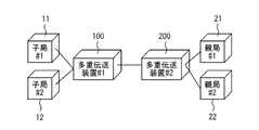
- FIG. 1is a diagram schematically showing an example of the overall configuration of the multiplex transmission system according to the first embodiment.
- the multiplex transmission system according to the present embodimentincludes a first multiplex transmission device 100 and a second multiplex transmission device 200.
- the multiplex transmission system of the present embodimentis a system in which a plurality of signals are multiplexed and transmitted between the first multiplex transmission device 100 and the second multiplex transmission device 200.
- the multiplex transmission system according to this disclosurecan be applied to a system using various well-known signal multiplexing methods.
- Specific signal multiplexing methodsinclude frequency division multiplexing (WDM: Waveringth Division Multiplex), frequency division multiplexing (FDM: Frequency Division Multiplex), time division multiplexing (TDM: Time Division Multiplex), and code division multiplexing (TDM).
- WDMWaveringth Division Multiplex
- FDMFrequency Division Multiplex
- TDMTime Division Multiplex
- TDMTime Division Multiplex
- CDMCode Division Multiplex
- the first multiplex transmission device 100 and the second multiplex transmission device 200are communicably connected by an optical fiber cable.
- the multiplex transmission systemby multiplexing a plurality of signals transmitted between two points, it is possible to reduce the number of optical fiber cables required for transmitting the plurality of signals between the two points.
- the first multiplex transmission device 100 and the second multiplex transmission device 200can be communicably connected by a single optical fiber cable.
- One or more slave stationsare connected to one of the first multiplex transmission device 100 and the second multiplex transmission device 200 so as to be able to communicate with each other.
- One or more master stationsare connected to the other of the first multiplex transmission device 100 and the second multiplex transmission device 200 so as to be able to communicate with each other.
- the first slave station 11 and the second slave station 12are connected to the first multiplex transmission device 100
- the first master station 21 and the second master station 22are connected to the second multiplex transmission device 200. There is.
- the multiplex transmission systemis applied to the mobile front hall.
- the first master station 21 and the second master station 22correspond to the CU (Central Unit) and / or the DU (Distributed Unit) of the base station.
- the first slave station 11 and the second slave station 12correspond to RU (Radio Unit).
- the first slave station 11 and the first master station 21are base stations of the first mobile carrier.
- the second slave station 12 and the second master station 22are base stations of the second mobile carrier.
- the first mobile carrier and the second mobile carrierare different mobile carriers (mobile communication carriers).
- An antennais connected to each slave station. Each antenna outputs radio waves to individual areas to form a reception area.
- Each master stationmay be formed as an individual device for each mobile carrier, or may be formed as an integrated device.
- each slave stationmay be formed as an individual device for each mobile carrier, or may be formed as an integrated device.
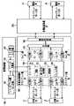
- FIG. 2is a block diagram showing a configuration of a multiplex transmission device included in the multiplex transmission system according to the first embodiment.
- the master station and the slave station connected to the first multiplex transmission device 100 and the second multiplex transmission device 200are collectively referred to as a client device here.
- Each of the first multiplex transmission device 100 and the second multiplex transmission device 200is provided with a plurality of client ports to which a client device can be connected.
- each of the first multiplex transmission device 100 and the second multiplex transmission device 200is provided with two client ports.
- the two client ports provided in the first multiplex transmission device 100are referred to as a first client port and a second client port.
- the two client ports provided in the second multiplex transmission device 200are referred to as a third client port and a fourth client port.
- “first”is indicated by “# 1”
- “second”is indicated by “# 2”
- "third”is indicated by “# 3”
- "fourth”is indicated by "#”. 4 ”.
- the first client port of the first multiplex transmission device 100is provided with an O / E unit 121 on the first client side and an E / O unit 122 on the first client side.
- the second client port of the first multiplex transmission device 100is provided with a second client-side O / E unit 123 and a second client-side E / O unit 124.
- the first multiplex transmission device 100includes a first line side E / O unit 111, a first line side O / E unit 112, a second line side E / O unit 113, a second line side O / E unit 114, and A first wave section 101 is further provided.
- the optical signal input to the first client port of the first multiplex transmission device 100is converted into an electric signal in the first client side O / E unit 121 and output to the first line side E / O unit 111.
- the first line side E / O unit 111converts the input electric signal into an optical signal and outputs it to the first combine unit 101.
- the optical signal input to the second client port of the first multiplex transmission device 100is converted into an electric signal in the second client side O / E unit 123 and output to the second line side E / O unit 113. ..
- the second line side E / O unit 113converts the input electric signal into an optical signal and outputs it to the first combine unit 101.
- the first wave section 101multiplexes the optical signals input from the first line side E / O section 111 and the second line side E / O section 113.
- the optical signal multiplexed in the first combiner section 101is transmitted from the first multiplex transmission device 100 to the second multiplex transmission device 200.
- the multiplexed optical signal transmitted from the second multiplex transmission device 200 to the first multiplex transmission device 100is input to the first combine unit 101.
- the first combiner section 101separates the multiplexed signal input from the second multiplex transmission device 200 and outputs it to each of the first line side O / E section 112 and the second line side O / E section 114. do.
- the first line side O / E unit 112converts the optical signal input from the first combine unit 101 into an electric signal and outputs it to the first client side E / O unit 122.
- the first client-side E / O unit 122converts the input electric signal into an optical signal and outputs it to the first client port of the first multiplex transmission device 100.
- the second line side O / E unit 114converts the optical signal input from the first combine unit 101 into an electric signal and outputs it to the second client side E / O unit 124.
- the second client-side E / O unit 124converts the input electric signal into an optical signal and outputs it to the second client port of the first multiplex transmission device 100.
- the first line side E / O unit 111, the first line side O / E unit 112, the first client side O / E unit 121, and the first client side E / O unit 122are the first multiplex transmission device. It corresponds to 100 first client ports.
- the second line side E / O unit 113, the second line side O / E unit 114, the second client side O / E unit 123, and the second client side E / O unit 124are the first multiplex transmission device 100. It corresponds to the second client port.
- the second multiplex transmission device 200is configured in the same manner as the first multiplex transmission device 100.
- the internal configuration of the second multiplex transmission device 200is not shown.
- the second multiplex transmission device 200is provided with a third client port and a fourth client port.
- the second multiplex transmission device 200includes a client-side O / E unit and an E / O unit corresponding to each client port.
- the second multiplex transmission device 200includes an O / E unit and an E / O unit on the line side corresponding to each client port.
- the second multiplex transmission device 200includes a second combiner that functions in the same manner as the first combiner 101.
- the line-side O / E section and E / O section of each multiplex transmission deviceare composed of an optical module that emits light at a fixed wavelength.
- the line-side O / E section and E / O section included in the first multiplex transmission device 100have the same wavelength as the line-side O / E section and E / O section of the second multiplex transmission device 200. Communication can only be performed with an optical module that emits light.
- each slave station and the first multiplex transmission device 100may be connected via a coupler (not shown) in order to construct a redundant configuration of a transmission line.
- each master station and the second multiplex transmission device 200may be connected via a coupler for constructing a redundant configuration of a transmission line.
- a switch capable of switching the transmission line provided inside each multiplex transmission devicemay be used to construct a redundant configuration of the transmission line between the base station and each multiplex transmission device.
- the first multiplex transmission device 100includes a first line switching unit 102 in order to construct a redundant configuration of transmission lines between the multiplex transmission devices.
- the second multiplex transmission device 200includes a second line switching unit that functions in the same manner as the first line switching unit 102.
- the line switching unitis for constructing a redundant configuration of transmission lines between multiplex transmission devices.
- the line switching portionsare connected by a plurality of paths (optical fiber cables). In the illustrated configuration example, the line switching portions are connected by two paths.
- a signal from the combine sectionis input to the line switching section.
- the line switching unitselects an arbitrary route from a plurality of routes connecting the line switching units, and outputs a signal from the combine unit to the selected line.
- the line switching unitmay be provided outside the multiplex transmission device.
- the first multiplex transmission device 100 and the second multiplex transmission device 200are connected by a plurality of switchable transmission paths.
- the first multiplex transmission device 100includes a resource pool 130.
- the resource pool 130has resources capable of selectively constructing one or more functions among a plurality of functions.
- the resource pool 130is composed of, for example, a rewritable FPGA.
- Various electrical functionscan be flexibly added to and removed from the resource pool 130.
- the resource pool 130partially or completely rewrites as necessary to build the necessary functions.
- the resource pool 130builds functions that are necessary or effective during normal times when no failure has occurred. Further, the resource pool 130 constructs a function for realizing a redundant configuration for dealing with a failure when a failure occurs.
- a redundant configurationis constructed using the resource pool 130 that functions both in normal times and when a failure occurs. This makes it possible to utilize resources more effectively than in the past. According to the present disclosure, it is possible to realize a redundant configuration for troubleshooting while reducing unnecessary resources.
- the resource pool 130may also be provided in the second multiplex transmission device 200.
- the resource pool 130may be provided in at least one of the first multiplex transmission device 100 and the second multiplex transmission device 200.
- the functional units that can be constructed in the resources of the resource pool 130are, for example, the SW unit 131, the error correction processing unit 132, the modulation unit 133, the filter unit 134, and the like.
- the SW unit 131has a switching function.
- the SW unit 131constructs a redundant path, for example, when a failure occurs in each O / E unit, each E / O unit, or other transmission / reception unit in the first multiplex transmission device 100.
- the error correction processing unit 132has a function of correcting the bit error rate due to signal deterioration occurring in the transmission line.
- the error correction processing unit 132detects and corrects an error on the receiving side based on the error correction code added to the data on the transmitting side.
- the error correction codefor example, an arbitrary code such as a Reed-Solomon code or an LDPC code is paid out.
- the error correction processing unit 132is constructed in the resource of the resource pool 130, for example, when the switching destination route becomes a long distance in the event of a line failure.
- the modulation unit 133has a function of multiplying the signal from the client port.
- the modulation unit 133generates, for example, a PAM4 signal.
- the bit ratecan be increased while maintaining the baud rate.
- the modulation unit 133for example, the cost of the O / E unit and the E / O unit can be reduced.
- the filter unit 134is for reducing the transmission speed, and has a function of filtering and discarding a part of the main signal.
- the multiplex transmission systemincludes a management control unit 140 as a control unit for controlling the resource pool 130.
- the management control unit 140includes, for example, a resource pool side monitor unit 141, a line side monitor unit 142, and a resource calculation unit 143.
- the management control unit 140is provided outside the first multiplex transmission device 100 in the illustrated configuration example, at least a part of the functions of the management control unit 140 is provided in the first multiplex transmission device 100. May be good. Further, at least a part of the functions of the management control unit 140 may be provided in the second multiplex transmission device 200.
- the resource pool side monitor unit 141monitors the current state of the resource pool 130.
- the monitoring information by the resource pool side monitor unit 141is sent to the resource calculation unit 143.
- the line side monitor unit 142monitors the states of the first line side E / O unit 111, the first line side O / E unit 112, the second line side E / O unit 113, and the second line side O / E unit 114. do.
- the monitoring information by the line side monitor unit 142is sent to the resource calculation unit 143.
- the line The side monitor unit 142notifies the resource calculation unit 143 of the failure.
- the resource calculation unit 143performs a calculation process for constructing each functional unit in the resource in the resource pool 130.
- the resource calculation unit 143performs calculation processing based on the monitoring information sent from the resource pool side monitor unit 141 and the line side monitor unit 142. Then, the resource calculation unit 143 issues an instruction to the resource pool 130 to construct a necessary functional unit based on the calculation processing result.
- the management control unit 140may be configured by a computer equipped with a processor and a memory as hardware.
- the processoris also referred to as a CPU (Central Processing Unit), a central processing unit, a processing unit, an arithmetic unit, a microprocessor, a microcomputer, or a DSP.
- Examples of the memoryinclude non-volatile or volatile semiconductor memories such as RAM, ROM, flash memory, EPROM and EEPROM, or magnetic disks, flexible disks, optical disks, compact disks, mini disks and DVDs.
- the program as softwareis stored in the memory of the management control unit 140.
- the management control unit 140executes preset processing by executing a program stored in the memory by the processor, and realizes each function as a result of the cooperation between the hardware and the software.
- the resource pool 130has functions related to each of the plurality of client ports in the normal time when no failure occurs.
- the management control unit 140controls the resource pool 130 so that a function related to each of the plurality of client ports is constructed.
- this control step in the normal timeis also referred to as a function construction step in the normal time.
- FIG. 3is a flow chart showing the flow of the resource control method of the multiplex transmission system according to the first embodiment.
- FIG. 3illustrates the operation when a failure occurs.
- a failureoccurs, first, in step S11, a resource in which a function related to a low priority port among a plurality of client ports is built is released.
- the process of step S11will also be referred to as a resource release step.
- step S12a function necessary for recovering the signal transmission related to the port having the higher priority among the plurality of client ports is constructed in the resource released by the resource release step.
- the process of step S12will also be referred to as a function reconstruction step.
- the functional reconstruction steppromptly restores the signal transmission associated with the higher priority port.
- the resource release step and the function reconstruction stepare carried out by the management control unit 140 controlling the resource pool 130.
- the resource control method as shown in FIG. 3and the multiplex transmission system configured to be able to execute the resource control method, it is possible to recover the communication on the high priority port in the event of a failure while reducing unnecessary resources.
- a redundant configurationcan be realized.
- a port with a low priorityis, for example, a best effort port.
- the high priority portis, for example, a traffic-guaranteed port.
- the priority of each portis determined, for example, when the port is set when the multiplex transmission system is installed. Further, for example, a traffic identifier of each port may be placed to monitor the packet quality (Cos value) of each port, and the port in which a large number of high-quality packets are flowing may be estimated as a high-priority port. ..
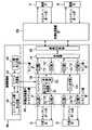
- FIG. 4is a block diagram illustrating an operation example of the multiplex transmission system according to the first embodiment in a normal time.
- FIG. 5is a block diagram illustrating an operation example when a failure occurs in the multiplex transmission system according to the first embodiment.
- the resource pool 130is constructed with a modulation unit 133 for multiplying the signals from each of the plurality of client ports as an example.
- FIG. 5illustrates the operation when a failure occurs in the transmission path connecting the first multiplex transmission device 100 and the second multiplex transmission device 200 in the multiplex transmission system configured as shown in FIG. ..
- the first client portis a high priority port and the second client port is a low priority port.
- the resource in which the modulation unit 133 related to the second client port is constructedis released.
- a filter unit 134that reduces the transmission speed at the second client port is constructed. For example, the transmission speed at the second client port is reduced from 25G to 10G.
- the open resourceis used to further construct the error correction processing unit 132 related to the first client port.
- the open resourceis used to further construct the error correction processing unit 132 related to the first client port.
- the operation of the multiplex transmission system according to the present disclosureis not limited to the examples shown in FIGS. 4 and 5.
- the SW unit 131when it is necessary to construct the SW unit 131 in order to restore the port having a high priority, the SW unit 131 is constructed in the resource pool 130.
- the functional unit constructed in the resource pool 130 in the normal timeis not limited to the modulation unit 133, and may be any functional unit according to the design of the multiplex transmission system.
- the multiplex transmission device constituting the multiplex transmission system and the resource control method of the multiplex transmission system according to the present disclosureare hardware in which preset processing is performed by the processor executing a program stored in the memory. It can also be achieved by linking hardware and software.
- the program for realizing the apparatus and method according to the present disclosurecan be recorded in an information recording medium.
- the program for realizing the apparatus and method according to the present disclosurecan also be provided through a communication network.
- the present disclosurecan be used for a multiplex transmission system in which a plurality of signals are multiplexed and transmitted between a first multiplex transmission device and a second multiplex transmission device, and resource control of the multiplex transmission system.
Landscapes
- Engineering & Computer Science (AREA)
- Computer Networks & Wireless Communication (AREA)
- Signal Processing (AREA)
- Physics & Mathematics (AREA)
- Electromagnetism (AREA)
- Data Exchanges In Wide-Area Networks (AREA)
- Optical Communication System (AREA)
- Small-Scale Networks (AREA)
Abstract
Description
Translated fromJapanese本開示は、多重伝送システムおよび多重伝送システムのリソース制御方法に関するものである。The present disclosure relates to a multiplex transmission system and a resource control method for the multiplex transmission system.
非特許文献1には、2地点間において複数の信号を多重化して伝送する多重伝送システムが開示されている。非特許文献1には、具体的には、波長分割多重化(WDM:Wavelength Division Multiplex)を用いて、複数の信号を多重化するものが開示されている。伝送する2つの地点のそれぞれには、波長の多重分離を行う多重伝送装置が設置される。Non-Patent
また、非特許文献2には、アクセス網の冗長技術が記載されている。多重伝送装置をつなぐ光ファイバーケーブルの断線または多重伝送装置内の送受信部(TRx)の故障等の各種の障害に対応するためには、非特許文献2に記載されているような冗長技術が必要となる。In addition, Non-Patent
非特許文献2に記載されているような従来の冗長技術においては、障害に備えて、多重伝送システムの導入の段階から予備系のリソースを予め準備しておく必要がある。従来の冗長技術において必要となる予備系のリソースは、障害が発生していない通常時においては、無駄なリソースとなってしまう。In the conventional redundant technology as described in Non-Patent
本開示は、このような課題を解決するためになされたものである。本開示の目的は、無駄なリソースを削減しつつ障害対応用の冗長構成を実現可能な多重伝送システムおよび多重伝送システムリソース制御方法を提供することにある。This disclosure is made to solve such problems. An object of the present disclosure is to provide a multiplex transmission system and a multiplex transmission system resource control method capable of realizing a redundant configuration for troubleshooting while reducing unnecessary resources.
本開示に係る多重伝送システムは、第1多重伝送装置と第2多重伝送装置との間で複数の信号を多重化して伝送する多重伝送システムにおいて、第1多重伝送装置に設けられ、複数の機能のうちの1つ以上の機能を選択的に構築可能なリソースを有するリソースプールと、リソースプールの制御を行う制御部と、を備えるものである。第1多重伝送装置は、クライアント装置を接続可能な複数のクライアントポートを備える。通常時において、リソースプールには、複数のクライアントポートのそれぞれに関連する機能が構築されている。障害の発生時において、制御部は、複数のクライアントポートのうちの優先度が低いポートに関連する機能が構築されているリソースを開放し、複数のクライアントポートのうちの優先度が高いポートに関連する信号伝送の復旧に必要な機能を当該リソースに構築するように、リソースプールを制御する。The multiplex transmission system according to the present disclosure is provided in the first multiplex transmission device in a multiplex transmission system in which a plurality of signals are multiplexed and transmitted between the first multiplex transmission device and the second multiplex transmission device, and has a plurality of functions. It includes a resource pool having resources capable of selectively constructing one or more of the functions, and a control unit for controlling the resource pool. The first multiplex transmission device includes a plurality of client ports to which client devices can be connected. In normal times, the resource pool has functions related to each of a plurality of client ports. In the event of a failure, the control unit releases resources for which functions related to the lower priority port of multiple client ports are built, and is related to the higher priority port of multiple client ports. The resource pool is controlled so that the functions necessary for the restoration of the signal transmission to be performed are built in the resource.
本開示に係る多重伝送システムのリソース制御方法は、第1多重伝送装置と第2多重伝送装置との間で複数の信号を多重化して伝送する多重伝送システムにおいて、第1多重伝送装置に設けられ、複数の機能のうちの1つ以上の機能を選択的に構築可能なリソースを有するリソースプールを制御する方法である。このリソース制御方法は、通常時において、リソースプールに、第1多重伝送装置に設けられた複数のクライアントポートのそれぞれに関連する機能を構築する通常時機能構築ステップと、障害の発生時において、複数のクライアントポートのうちの優先度が低いポートに関連する機能が構築されているリソースを開放するリソース開放ステップと、リソース開放ステップによって開放したリソースに、複数のクライアントポートのうちの優先度が高いポートに関連する信号伝送の復旧に必要な機能を構築する機能再構築ステップと、を備える。The resource control method of the multiplex transmission system according to the present disclosure is provided in the first multiplex transmission device in the multiplex transmission system in which a plurality of signals are multiplexed and transmitted between the first multiplex transmission device and the second multiplex transmission device. , A method of controlling a resource pool having resources capable of selectively constructing one or more of a plurality of functions. This resource control method has a plurality of normal function construction steps for constructing functions related to each of a plurality of client ports provided in the first multiplex transmission device in the resource pool during normal times, and a plurality of normal function construction steps when a failure occurs. A resource release step that releases a resource for which a function related to a low-priority port is built, and a high-priority port among multiple client ports for the resource released by the resource release step. It comprises a function restructuring step, which builds the functions necessary for the restoration of the signal transmission related to.
本開示に係る多重伝送システムおよび多重伝送システムのリソース制御方法によれば、無駄なリソースを削減しつつ障害対応用の冗長構成を実現することができる。According to the multiplex transmission system and the resource control method of the multiplex transmission system according to the present disclosure, it is possible to realize a redundant configuration for troubleshooting while reducing unnecessary resources.
本開示に係る多重伝送システムおよび多重伝送システムのリソース制御方法を実施するための形態について、添付の図面を参照しながら説明する。各図において、同一又は相当する部分には同一の符号を付して、重複する説明は適宜に簡略化又は省略する。なお、本開示は以下の実施の形態に限定されることなく、本開示の趣旨を逸脱しない範囲において、実施の形態によって開示される任意の構成要素の変形または省略が可能である。The mode for implementing the multiplex transmission system and the resource control method of the multiplex transmission system according to the present disclosure will be described with reference to the attached drawings. In each figure, the same or corresponding parts are designated by the same reference numerals, and duplicate description will be appropriately simplified or omitted. The present disclosure is not limited to the following embodiments, and any component disclosed by the embodiments can be modified or omitted without departing from the spirit of the present disclosure.
実施の形態1.
図1は、実施の形態1に係る多重伝送システムの全体構成の一例を模式的に示す図である。本実施の形態に係る多重伝送システムは、図1に示すように、第1多重伝送装置100および第2多重伝送装置200を備えている。本実施の形態の多重伝送システムは、第1多重伝送装置100と第2多重伝送装置200との間で複数の信号を多重化して伝送するシステムである。この開示に係る多重伝送システムは、周知である各種の信号多重化方法を使用したシステムに適用可能である。具体的な信号多重化方法としては、波長分割多重化(WDM:Wavelength Division Multiplex)、周波数分割多重化(FDM:Frequency Division Multiplex)、時分割多重化(TDM:Time Division Multiplex)、符号分割多重化(CDM:Code Division Multiplex)等を挙げることができる。ここでは、波長分割多重化(WDM)を使用した場合の例について説明する。
FIG. 1 is a diagram schematically showing an example of the overall configuration of the multiplex transmission system according to the first embodiment. As shown in FIG. 1, the multiplex transmission system according to the present embodiment includes a first
第1多重伝送装置100と第2多重伝送装置200とは、光ファイバーケーブルにより通信可能に接続されている。多重伝送システムによれば、2点間で伝送される複数の信号を多重化することで、複数の信号を2点間で伝送するための必要な光ファイバーケーブルの本数を削減することができる。例えば、第1多重伝送装置100と第2多重伝送装置200とは、1本の光ファイバーケーブルによって通信可能に接続することができる。The first
第1多重伝送装置100および第2多重伝送装置200の一方には、1つ以上の子局が、通信可能なように接続される。第1多重伝送装置100および第2多重伝送装置200の他方には、1つ以上の親局が、通信可能なように接続される。図示の構成例では、第1多重伝送装置100に第1子局11および第2子局12が接続され、第2多重伝送装置200に第1親局21および第2親局22が接続されている。One or more slave stations are connected to one of the first
本実施の形態において、多重伝送システムは、モバイルフロントホールに適用されているとする。この場合、第1親局21および第2親局22は、基地局のCU(Central Unit)および/またはDU(Distributed Unit)にあたる。また、この場合、第1子局11および第2子局12はRU(Radio Unit)にあたる。第1子局11および第1親局21は、第1モバイルキャリアの基地局である。第2子局12および第2親局22は、第2モバイルキャリアの基地局である。第1モバイルキャリアと第2モバイルキャリアとは、異なるモバイルキャリア(移動体通信事業者)である。各子局には、アンテナが接続されている。各アンテナは、個別のエリアに対して電波を出力して、受信エリアを形成する。なお、各親局は、モバイルキャリア毎に個別の装置として形成されていてもよいし、一体化された装置として形成されてもよい。同様に、各子局も、モバイルキャリア毎に個別の装置として形成されていてもよいし、一体化された装置として形成されてもよい。In this embodiment, it is assumed that the multiplex transmission system is applied to the mobile front hall. In this case, the
図2は、実施の形態1に係る多重伝送システムが備える多重伝送装置の構成を示すブロック図である。第1多重伝送装置100および第2多重伝送装置200に接続される親局および子局を総称して、ここではクライアント装置と呼ぶ。第1多重伝送装置100および第2多重伝送装置200のそれぞれは、クライアント装置を接続可能な複数のクライアントポートが設けられている。図示の構成例では、第1多重伝送装置100および第2多重伝送装置200それぞれには、2つずつクライアントポートが設けられている。区別を容易にするため、第1多重伝送装置100に設けられている2つのクライアントポートを第1クライアントポートおよび第2クライアントポートと呼ぶ。また、第2多重伝送装置200に設けられている2つのクライアントポートを第3クライアントポートおよび第4クライアントポートと呼ぶ。なお、各図においては、「第1」を「#1」で示し、「第2」を「#2」で示し、「第3」を「#3」で示し、「第4」を「#4」で示している。FIG. 2 is a block diagram showing a configuration of a multiplex transmission device included in the multiplex transmission system according to the first embodiment. The master station and the slave station connected to the first
第1多重伝送装置100の第1クライアントポートには、第1クライアント側O/E部121および第1クライアント側E/O部122が設けられている。第1多重伝送装置100の第2クライアントポートには、第2クライアント側O/E部123および第2クライアント側E/O部124が設けられている。第1多重伝送装置100は、第1ライン側E/O部111、第1ライン側O/E部112、第2ライン側E/O部113および第2ライン側O/E部114、並びに、第1合波部101をさらに備えている。The first client port of the first
第1多重伝送装置100の第1クライアントポートに入力された光信号は、第1クライアント側O/E部121において電気信号に変換され、第1ライン側E/O部111に出力される。第1ライン側E/O部111は、入力された電気信号を光信号に変換して第1合波部101に出力する。また、第1多重伝送装置100の第2クライアントポートに入力された光信号は、第2クライアント側O/E部123において電気信号に変換され、第2ライン側E/O部113に出力される。第2ライン側E/O部113は、入力された電気信号を光信号に変換して第1合波部101に出力する。The optical signal input to the first client port of the first
第1合波部101は、第1ライン側E/O部111および第2ライン側E/O部113から入力された光信号を多重化する。第1合波部101において多重化された光信号は、第1多重伝送装置100から第2多重伝送装置200に送信される。The
また、第2多重伝送装置200から第1多重伝送装置100に送信される多重化された光信号は、第1合波部101に入力される。第1合波部101は、第2多重伝送装置200から入力された多重化された信号を分離し、第1ライン側O/E部112および第2ライン側O/E部114のそれぞれに出力する。Further, the multiplexed optical signal transmitted from the second
第1ライン側O/E部112は、第1合波部101から入力された光信号を電気信号に変換して第1クライアント側E/O部122に出力する。第1クライアント側E/O部122は、入力された電気信号を光信号に変換して第1多重伝送装置100の第1クライアントポートに出力する。第2ライン側O/E部114は、第1合波部101から入力された光信号を電気信号に変換して第2クライアント側E/O部124に出力する。第2クライアント側E/O部124は、入力された電気信号を光信号に変換して第1多重伝送装置100の第2クライアントポートに出力する。The first line side O /
このように、第1ライン側E/O部111、第1ライン側O/E部112、第1クライアント側O/E部121および第1クライアント側E/O部122は、第1多重伝送装置100の第1クライアントポートに対応している。また、第2ライン側E/O部113、第2ライン側O/E部114、第2クライアント側O/E部123および第2クライアント側E/O部124は、第1多重伝送装置100の第2クライアントポートに対応している。As described above, the first line side E / O unit 111, the first line side O /
第2多重伝送装置200は、第1多重伝送装置100と同様に構成される。第2多重伝送装置200の内部構成については図示を省略する。上述したように、第2多重伝送装置200には、第3クライアントポートおよび第4クライアントポートが設けられている。第2多重伝送装置200は、各クライアントポートに対応するクライアント側のO/E部およびE/O部を備える。第2多重伝送装置200は、各クライアントポートに対応するライン側のO/E部およびE/O部を備える。また、第2多重伝送装置200は、第1合波部101と同様に機能する第2合波部を備える。The second
各多重伝送装置が備えるライン側のO/E部およびE/O部は、固定の波長で発光する光モジュールで構成される。第1多重伝送装置100が備えるライン側のO/E部およびE/O部は、第2多重伝送装置200が備えるライン側のO/E部およびE/O部のうち、自身と同じ波長で発光する光モジュールとの間でのみ通信を行うことができる。The line-side O / E section and E / O section of each multiplex transmission device are composed of an optical module that emits light at a fixed wavelength. The line-side O / E section and E / O section included in the first
なお、各子局と第1多重伝送装置100とは、伝送路の冗長構成を構築するため、図示しないカプラを介して接続されていてもよい。同様に、各親局と第2多重伝送装置200とは、伝送路の冗長構成を構築するためのカプラを介して接続されていてもよい。また、カプラの代わりに、各多重伝送装置の内部に設けられた伝送路を切り替え可能なスイッチを用いて、基地局と各多重伝送装置との伝送路の冗長構成を構築してもよい。Note that each slave station and the first
図示の構成例では、第1多重伝送装置100は、多重伝送装置間の伝送路の冗長構成を構築するため、第1線路切替部102を備えている。図示を省略するが、第2多重伝送装置200は、第1線路切替部102と同様に機能する第2線路切替部を備える。線路切替部は、多重伝送装置間の伝送路の冗長構成を構築するためのものである。線路切替部同士は、複数の経路(光ファイバーケーブル)によって接続される。図示の構成例において、線路切替部同士は、2つの経路によって繋がれている。線路切替部には、合波部からの信号が入力される。線路切替部は、線路切替部同士を繋ぐ複数の経路のうちの任意の経路を選択し、選択した線路に対して合波部からの信号を出力する。なお、線路切替部は、多重伝送装置の外部に設けられていてもよい。このように、本実施の形態において、第1多重伝送装置100と第2多重伝送装置200とは、切り替え可能な複数の伝送経路によって接続されている。In the illustrated configuration example, the first
また、図2に示すように、本実施の形態において、第1多重伝送装置100は、リソースプール130を備える。リソースプール130は、複数の機能のうちの1つ以上の機能を選択的に構築可能なリソースを有する。リソースプール130は、例えば、書き換え可能なFPGAから構成される。リソースプール130には、各種の電気的機能を、柔軟に追加および削除することができる。リソースプール130は、必要に応じて、部分的もしくはその全部を書き換えて、必要な機能を構築する。リソースプール130は、障害が発生していない通常時には、通常時に必要または有効な機能を構築する。また、リソースプール130は、障害発生時には、障害対応用の冗長構成を実現するための機能を構築する。Further, as shown in FIG. 2, in the present embodiment, the first
本開示では、通常時および障害発生時の何れにおいても機能するリソースプール130を用いて冗長構成を構築する。これにより、従来に比べて有効にリソースを活用することが可能となる。本開示によれば、無駄なリソースを削減しつつ障害対応用の冗長構成を実現することができる。In the present disclosure, a redundant configuration is constructed using the
なお、リソースプール130は、第2多重伝送装置200にも備えられていてもよい。本開示において、リソースプール130は、第1多重伝送装置100および第2多重伝送装置200の少なくとも一方に備えられていればよい。The
リソースプール130のリソースに構築可能な機能部は、例えば、SW部131、誤り訂正処理部132、変調部133およびフィルタ部134等である。SW部131は、スイッチング機能を有するものである。SW部131は、例えば、第1多重伝送装置100内の各O/E部および各E/O部等の送受信部に障害が生じた場合において、冗長経路を構築する。The functional units that can be constructed in the resources of the
誤り訂正処理部132は、伝送路で発生する信号劣化によるビット誤り率を訂正する機能を有するものである。誤り訂正処理部132は、送信側でデータに付加された誤り訂正符号を基に、受信側で誤りを検出して訂正する。誤り訂正符号には、例えば、リードソロモン符号またはLDPC符号等の任意の符号が配当する。誤り訂正処理部132は、例えば、線路故障の際、切替先の経路が長距離となる場合に、リソースプール130のリソースに構築される。The error
変調部133は、クライアントポートからの信号を多値化する機能を有するものである。変調部133は、例えば、PAM4信号を生成する。変調部133によれば、ボーレートを維持しつつ、ビットレートを高速化することができる。変調部133によれば、例えば、O/E部およびE/O部のコストを低減することができる。The
フィルタ部134は、伝送速度を下げるためのものであり、主信号の一部をフィルタリングして廃棄する機能を有するものである。The
また、本実施の形態に係る多重伝送システムは、リソースプール130を制御する制御部として、管理制御部140を備える。管理制御部140は、例えば、リソースプール側モニタ部141、ライン側モニタ部142およびリソース計算部143を備える。なお、図示の構成例において管理制御部140は第1多重伝送装置100の外に設けられているが、管理制御部140の少なくとも一部の機能が第1多重伝送装置100内に備えられていてもよい。また、管理制御部140の少なくとも一部の機能は、第2多重伝送装置200内に備えられていてもよい。Further, the multiplex transmission system according to the present embodiment includes a
リソースプール側モニタ部141は、リソースプール130の現在の状態をモニタリングする。リソースプール側モニタ部141によるモニタリング情報は、リソース計算部143へ送られる。ライン側モニタ部142は、第1ライン側E/O部111、第1ライン側O/E部112、第2ライン側E/O部113および第2ライン側O/E部114の状態をモニタリングする。ライン側モニタ部142によるモニタリング情報は、リソース計算部143へ送られる。例えば、第1ライン側E/O部111、第1ライン側O/E部112、第2ライン側E/O部113および第2ライン側O/E部114の何れかが故障した場合、ライン側モニタ部142はリソース計算部143に対して故障通知を行う。リソース計算部143は、リソースプール130内のリソースに各機能部を構築するための計算処理を行う。リソース計算部143は、リソースプール側モニタ部141およびライン側モニタ部142から送られるモニタリング情報に基づいて、計算処理を行う。そして、リソース計算部143は、計算処理結果に基づいて、必要な機能部を構築するようにリソースプール130に指示を出す。The resource pool
管理制御部140は、ハードウェアとして、プロセッサおよびメモリを備えたコンピュータにより構成してもよい。プロセッサは、CPU(Central Processing Unit)、中央処理装置、処理装置、演算装置、マイクロプロセッサ、マイクロコンピュータあるいはDSPともいう。メモリには、例えば、RAM、ROM、フラッシュメモリー、EPROMおよびEEPROM等の不揮発性または揮発性の半導体メモリ、又は、磁気ディスク、フレキシブルディスク、光ディスク、コンパクトディスク、ミニディスクおよびDVD等が該当する。The
管理制御部140のメモリには、ソフトウェアとしてのプログラムが記憶される。管理制御部140は、メモリに記憶されたプログラムをプロセッサが実行することによって予め設定された処理を実施し、ハードウェアとソフトウェアとが協働した結果として、各機能を実現する。The program as software is stored in the memory of the
次に、以上のように構成された多重伝送システムの動作の流れについて説明する。前提として、障害の発生していない通常時においては、リソースプール130には、複数のクライアントポートのそれぞれに関連する機能が構築されているものとする。通常時において、管理制御部140は、複数のクライアントポートのそれぞれに関連する機能が構築されるようにリソースプール130を制御している。通常時におけるこの制御ステップを、本開示では、通常時機能構築ステップとも称することとする。Next, the operation flow of the multiplex transmission system configured as described above will be explained. As a premise, it is assumed that the
図3は、実施の形態1に係る多重伝送システムのリソース制御方法の流れを示すフロー図である。図3は、障害の発生時における動作を説明するものである。障害が発生すると、まず、ステップS11において、複数のクライアントポートのうちの優先度が低いポートに関連する機能が構築されているリソースを開放する。このステップS11の処理を、本開示では、リソース開放ステップとも称することとする。FIG. 3 is a flow chart showing the flow of the resource control method of the multiplex transmission system according to the first embodiment. FIG. 3 illustrates the operation when a failure occurs. When a failure occurs, first, in step S11, a resource in which a function related to a low priority port among a plurality of client ports is built is released. In the present disclosure, the process of step S11 will also be referred to as a resource release step.
続くステップS12において、リソース開放ステップによって開放したリソースに、複数のクライアントポートのうちの優先度が高いポートに関連する信号伝送の復旧に必要な機能を構築する。このステップS12の処理を、本開示では、機能再構築ステップとも称することとする。機能再構築ステップによって、優先度が高いポートに関連する信号伝送の復旧が、速やかに行われる。リソース開放ステップおよび機能再構築ステップは、管理制御部140がリソースプール130を制御することによって実施される。In the following step S12, a function necessary for recovering the signal transmission related to the port having the higher priority among the plurality of client ports is constructed in the resource released by the resource release step. In the present disclosure, the process of step S12 will also be referred to as a function reconstruction step. The functional reconstruction step promptly restores the signal transmission associated with the higher priority port. The resource release step and the function reconstruction step are carried out by the
図3に示すようなリソース制御方法および当該リソース制御方法を実行可能に構成された多重伝送システムによれば、無駄なリソースを削減しつつ、障害発生時に優先度の高いポートにおける通信を復旧可能な冗長構成を実現することができる。According to the resource control method as shown in FIG. 3 and the multiplex transmission system configured to be able to execute the resource control method, it is possible to recover the communication on the high priority port in the event of a failure while reducing unnecessary resources. A redundant configuration can be realized.
優先度が低いポートは、例えば、ベストエフォートのポートである。優先度が高いポートは、例えば、トラヒック保障のポートである。各ポートの優先度は、例えば、多重伝送システムの設置時におけるポート設定時に決められる。また、例えば、各ポートのトラヒック識別子を置いて、各ポートにおけるパケットの品質(Cos値)をモニタリングして、品質の高いパケットが多く流れているポートを優先度が高いポートとして推定してもよい。A port with a low priority is, for example, a best effort port. The high priority port is, for example, a traffic-guaranteed port. The priority of each port is determined, for example, when the port is set when the multiplex transmission system is installed. Further, for example, a traffic identifier of each port may be placed to monitor the packet quality (Cos value) of each port, and the port in which a large number of high-quality packets are flowing may be estimated as a high-priority port. ..
図4は、実施の形態1に係る多重伝送システムの通常時における動作例を説明するブロック図である。図5は、実施の形態1に係る多重伝送システムの障害発生時における動作例を説明するブロック図である。図4に示すように、通常時において、リソースプール130には、一例として、複数のクライアントポートのそれぞれからの信号を多値化する変調部133が構築されている。FIG. 4 is a block diagram illustrating an operation example of the multiplex transmission system according to the first embodiment in a normal time. FIG. 5 is a block diagram illustrating an operation example when a failure occurs in the multiplex transmission system according to the first embodiment. As shown in FIG. 4, in the normal time, the
図5は、図4に示すように構成された多重伝送システムにおいて、第1多重伝送装置100と第2多重伝送装置200とを繋ぐ伝送経路に障害が発生した場合の動作を説明するものである。図4および図5の例においては、第1クライアントポートが優先度の高いポートであり、第2クライアントポートが優先度の低いポートである。図4および図5の例においては、障害の発生時、第2クライアントポートに関連する変調部133が構築されているリソースが開放される。そして、開放したリソースを用いて、第2クライアントポートでの伝送速度を下げるフィルタ部134を構築する。例えば、第2クライアントポートでの伝送速度を、25Gから10Gへと下げる。FIG. 5 illustrates the operation when a failure occurs in the transmission path connecting the first
また、図4および図5の例においては、障害の発生時、開放したリソースを用いて、第1クライアントポートに関連する誤り訂正処理部132を更に構築する。これにより、障害発生時における伝送路の切替先が長距離となる場合においても、優先度の高いポートでの信号伝送を誤りなく行うことができる。Further, in the examples of FIGS. 4 and 5, when a failure occurs, the open resource is used to further construct the error
なお、本開示に係る多重伝送システムの動作は、図4および図5に示す例に限定されるものではない。例えば、優先度の高いポートを復旧させるためにSW部131の構築が必要である場合には、SW部131がリソースプール130に構築される。また、通常時においてリソースプール130に構築される機能部は、変調部133に限られず、多重伝送システムの設計に応じた任意の機能部でよい。The operation of the multiplex transmission system according to the present disclosure is not limited to the examples shown in FIGS. 4 and 5. For example, when it is necessary to construct the
また、本開示に係る多重伝送システムを構成する多重伝送装置、および、多重伝送システムのリソース制御方法は、メモリに記憶されたプログラムをプロセッサが実行することによって予め設定された処理を実施し、ハードウェアとソフトウェアとを協働させることでも実現できる。そして、本開示に係る装置および方法を実現するためのプログラムは情報記録媒体に記録しておくことが可能である。また、本開示に係る装置および方法を実現するためのプログラムは、通信ネットワークを通して提供することも可能である。Further, the multiplex transmission device constituting the multiplex transmission system and the resource control method of the multiplex transmission system according to the present disclosure are hardware in which preset processing is performed by the processor executing a program stored in the memory. It can also be achieved by linking hardware and software. The program for realizing the apparatus and method according to the present disclosure can be recorded in an information recording medium. In addition, the program for realizing the apparatus and method according to the present disclosure can also be provided through a communication network.
本開示は、第1多重伝送装置と第2多重伝送装置との間で複数の信号を多重化して伝送する多重伝送システムおよび当該多重伝送システムのリソース制御に利用できる。The present disclosure can be used for a multiplex transmission system in which a plurality of signals are multiplexed and transmitted between a first multiplex transmission device and a second multiplex transmission device, and resource control of the multiplex transmission system.
11 第1子局
12 第2子局
21 第1親局
22 第2親局
100 第1多重伝送装置
101 第1合波部
102 第1線路切替部
111 第1ライン側E/O部
112 第1ライン側O/E部
113 第2ライン側E/O部
114 第2ライン側O/E部
121 第1クライアント側O/E部
122 第1クライアント側E/O部
123 第2クライアント側O/E部
124 第2クライアント側E/O部
130 リソースプール
131 SW部
132 誤り訂正処理部
133 変調部
134 フィルタ部
140 管理制御部
141 リソースプール側モニタ部
142 ライン側モニタ部
143 リソース計算部
200 第2多重伝送装置11
Claims (4)
Translated fromJapanese前記第1多重伝送装置に設けられ、複数の機能のうちの1つ以上の機能を選択的に構築可能なリソースを有するリソースプールと、
前記リソースプールの制御を行う制御部と、
を備え、
前記第1多重伝送装置は、クライアント装置を接続可能な複数のクライアントポートを備え、
通常時において、前記リソースプールには、前記複数のクライアントポートのそれぞれに関連する機能が構築され、
障害の発生時において、前記制御部は、前記複数のクライアントポートのうちの優先度が低いポートに関連する機能が構築されているリソースを開放し、前記複数のクライアントポートのうちの優先度が高いポートに関連する信号伝送の復旧に必要な機能を当該リソースに構築するように、前記リソースプールを制御する多重伝送システム。
In a multiplex transmission system in which a plurality of signals are multiplexed and transmitted between a first multiplex transmission device and a second multiplex transmission device.
A resource pool provided in the first multiplex transmission device and having resources capable of selectively constructing one or more of a plurality of functions, and a resource pool.
A control unit that controls the resource pool and
Equipped with
The first multiplex transmission device includes a plurality of client ports to which a client device can be connected.
In normal times, the resource pool is constructed with functions related to each of the plurality of client ports.
In the event of a failure, the control unit releases resources for which functions related to the low priority port among the plurality of client ports are built, and the priority among the plurality of client ports is high. A multiplex transmission system that controls the resource pool so that the resource has the functions required to restore the signal transmission related to the port.
前記制御部は、前記優先度が低いポートに関連する変調部が構築されているリソースを開放し、当該リソースを用いて前記優先度が高いポートに関連する誤り訂正処理部および前記優先度が低いポートでの伝送速度を下げるフィルタ部を構築するように、前記リソースプールを制御する請求項1に記載の多重伝送システム。
In the normal time, a modulation unit for multiplying the signals from each of the plurality of client ports is constructed in the resource pool.
The control unit releases a resource in which a modulation unit related to the low-priority port is constructed, and uses the resource to perform an error correction processing unit related to the high-priority port and the low-priority port. The multiplex transmission system according to claim 1, wherein the resource pool is controlled so as to construct a filter unit that reduces the transmission speed at the port.
通常時において、前記リソースプールに、前記第1多重伝送装置に設けられた複数のクライアントポートのそれぞれに関連する機能を構築する通常時機能構築ステップと、
障害の発生時において、前記複数のクライアントポートのうちの優先度が低いポートに関連する機能が構築されているリソースを開放するリソース開放ステップと、
前記リソース開放ステップによって開放したリソースに、前記複数のクライアントポートのうちの優先度が高いポートに関連する信号伝送の復旧に必要な機能を構築する機能再構築ステップと、
を備える多重伝送システムのリソース制御方法。In a multiplex transmission system in which a plurality of signals are multiplexed and transmitted between a first multiplex transmission device and a second multiplex transmission device, the first multiplex transmission device is provided with one or more functions among the plurality of functions. Is a method of controlling a resource pool that has resources that can be selectively constructed.
In the normal time, the normal time function construction step for constructing the function related to each of the plurality of client ports provided in the first multiplex transmission device in the resource pool, and the normal time function construction step.
A resource release step that releases a resource for which a function related to a port having a lower priority among the plurality of client ports is built in the event of a failure.
A function rebuilding step for constructing a function necessary for recovering a signal transmission related to a port having a higher priority among the plurality of client ports in the resource released by the resource release step, and a function reconstruction step.
A resource control method for a multiplex transmission system.
前記機能再構築ステップでは、前記優先度が高いポートに関連する誤り訂正処理部および前記優先度が低いポートでの伝送速度を下げるためのフィルタ部を構築する請求項3に記載の多重伝送システムのリソース制御方法。In the normal function construction step, a modulation unit that multivalues the signals from each of the plurality of client ports is constructed in the resource pool.
The multiplex transmission system according to claim 3, wherein in the functional reconstruction step, an error correction processing unit related to the high-priority port and a filter unit for reducing the transmission speed in the low-priority port are constructed. Resource control method.
Priority Applications (3)
| Application Number | Priority Date | Filing Date | Title |
|---|---|---|---|
| PCT/JP2020/038013WO2022074763A1 (en) | 2020-10-07 | 2020-10-07 | Multiplex transmission system and resource control method for multiplex transmission system |
| JP2022555028AJP7444274B2 (en) | 2020-10-07 | 2020-10-07 | Multiplex transmission system and resource control method for multiplex transmission system |
| US18/028,631US20230361867A1 (en) | 2020-10-07 | 2020-10-07 | Multiplex transmission system, resource control method for multiplex transmission system |
Applications Claiming Priority (1)
| Application Number | Priority Date | Filing Date | Title |
|---|---|---|---|
| PCT/JP2020/038013WO2022074763A1 (en) | 2020-10-07 | 2020-10-07 | Multiplex transmission system and resource control method for multiplex transmission system |
Publications (1)
| Publication Number | Publication Date |
|---|---|
| WO2022074763A1true WO2022074763A1 (en) | 2022-04-14 |
Family
ID=81125742
Family Applications (1)
| Application Number | Title | Priority Date | Filing Date |
|---|---|---|---|
| PCT/JP2020/038013CeasedWO2022074763A1 (en) | 2020-10-07 | 2020-10-07 | Multiplex transmission system and resource control method for multiplex transmission system |
Country Status (3)
| Country | Link |
|---|---|
| US (1) | US20230361867A1 (en) |
| JP (1) | JP7444274B2 (en) |
| WO (1) | WO2022074763A1 (en) |
Citations (2)
| Publication number | Priority date | Publication date | Assignee | Title |
|---|---|---|---|---|
| JPH0275055A (en)* | 1988-09-12 | 1990-03-14 | Fuji Electric Co Ltd | How to switch between main and slave systems in multiple computer systems |
| JP2006166037A (en)* | 2004-12-08 | 2006-06-22 | Fujitsu Ltd | Optical transmission device and optical transmission system |
Family Cites Families (6)
| Publication number | Priority date | Publication date | Assignee | Title |
|---|---|---|---|---|
| US20030023709A1 (en)* | 2001-02-28 | 2003-01-30 | Alvarez Mario F. | Embedded controller and node management architecture for a modular optical network, and methods and apparatus therefor |
| EP1280374A1 (en)* | 2001-07-27 | 2003-01-29 | Alcatel | Network element with redundant switching matrix |
| JP4562443B2 (en)* | 2004-07-15 | 2010-10-13 | 富士通株式会社 | Optical transmission system and optical transmission method |
| JP5211766B2 (en)* | 2008-03-10 | 2013-06-12 | 富士通株式会社 | Resource allocation apparatus and program |
| JP2010205209A (en)* | 2009-03-06 | 2010-09-16 | Hitachi Ltd | Management computer, computer system, and physical resource allocating method |
| US20140093231A1 (en)* | 2012-10-02 | 2014-04-03 | Kenneth Martin Fisher | Procedure, apparatus, system, and computer program for network recovery |
- 2020
- 2020-10-07WOPCT/JP2020/038013patent/WO2022074763A1/ennot_activeCeased
- 2020-10-07USUS18/028,631patent/US20230361867A1/ennot_activeAbandoned
- 2020-10-07JPJP2022555028Apatent/JP7444274B2/enactiveActive
Patent Citations (2)
| Publication number | Priority date | Publication date | Assignee | Title |
|---|---|---|---|---|
| JPH0275055A (en)* | 1988-09-12 | 1990-03-14 | Fuji Electric Co Ltd | How to switch between main and slave systems in multiple computer systems |
| JP2006166037A (en)* | 2004-12-08 | 2006-06-22 | Fujitsu Ltd | Optical transmission device and optical transmission system |
Non-Patent Citations (2)
| Title |
|---|
| SATORU OKAMOTO, JUN MATSUMOTO, TAKEHIRO SATO, NAOAKI YAMANAKAL: "Proposal of the Photonic Programmable Node Architecture using Virtual Reconfigurable Communication Processors", IEICE TECHNICAL REPORT, vol. 116, no. 205 (PN2016-24), 25 August 2016 (2016-08-25), JP , pages 59 - 64, XP009536622, ISSN: 0913-5685* |
| TANIMURA, TAKAHITO ET AL.: "Experimental feasibility study of latency and bandwidth programmable optical transceiver by using hybrid Nyquist FDM technique", IEICE TECHNICAL REPORT, vol. 116, no. 164, 21 July 2016 (2016-07-21), pages 5 - 10* |
Also Published As
| Publication number | Publication date |
|---|---|
| JP7444274B2 (en) | 2024-03-06 |
| JPWO2022074763A1 (en) | 2022-04-14 |
| US20230361867A1 (en) | 2023-11-09 |
Similar Documents
| Publication | Publication Date | Title |
|---|---|---|
| US9882634B1 (en) | Coordinated connection validation systems and methods among mated transceivers for verifying optical and data plane connectivity | |
| US11870487B2 (en) | Method for supporting SNCP over packet network | |
| US8693880B2 (en) | Wavelength path communication node apparatus, wavelength path communication control method, and recording medium | |
| US7206508B2 (en) | Method and apparatus for operation, protection, and restoration of heterogeneous optical communication networks | |
| US20040240884A1 (en) | Optical ring network with selective signal regeneration and wavelength conversion | |
| JP2005521330A (en) | Supervisory channel in optical network systems | |
| US9680564B2 (en) | Protection in metro optical networks | |
| US20080050117A1 (en) | Method and apparatus for photonic resiliency of a packet switched network | |
| US20180076882A1 (en) | Horizontal synchronization extensions for service resizing in optical networks | |
| JP4538302B2 (en) | Optical ring network and method with optical subnet | |
| EP3244580A1 (en) | Network service establishment method, cooperation control centre and network system | |
| JP5206211B2 (en) | WDM network and node equipment | |
| JP3886891B2 (en) | COMMUNICATION SYSTEM, COMMUNICATION DEVICE AND NETWORK MANAGEMENT DEVICE USED IN THE COMMUNICATION SYSTEM | |
| US20110164622A1 (en) | Operation and construction method of network using multi-rate interface panel | |
| CN110113258B (en) | Method and system for automatically protecting data surface link by using control surface link | |
| Uematsu et al. | Future nationwide optical network architecture for higher availability and operability using transport SDN technologies | |
| WO2022074763A1 (en) | Multiplex transmission system and resource control method for multiplex transmission system | |
| JP7485065B2 (en) | Multiplex transmission system and resource control method for multiplex transmission system | |
| EP2757715B1 (en) | Optical transmission link protection device | |
| Ramamurthy et al. | Cost and reliability considerations in designing the next-generation IP over WDM backbone networks | |
| JP7435813B2 (en) | Multiplex transmission system and resource control method for multiplex transmission system | |
| JP6507530B2 (en) | Optical network and network control device | |
| CN109743112B (en) | OTN networking method, apparatus, device, and computer-readable storage medium | |
| JP4488813B2 (en) | Method and system for managing directly connected optical elements | |
| Xu et al. | Multicarrier-collaboration-based emergency packet transport network construction in disaster recovery |
Legal Events
| Date | Code | Title | Description |
|---|---|---|---|
| ENP | Entry into the national phase | Ref document number:2022555028 Country of ref document:JP Kind code of ref document:A | |
| NENP | Non-entry into the national phase | Ref country code:DE | |
| 122 | Ep: pct application non-entry in european phase | Ref document number:20956711 Country of ref document:EP Kind code of ref document:A1 |