WO2022071642A1 - Method and apparatus for performing channel coding of ue and base station in wireless communication system - Google Patents
Method and apparatus for performing channel coding of ue and base station in wireless communication systemDownload PDFInfo
- Publication number
- WO2022071642A1 WO2022071642A1PCT/KR2021/006104KR2021006104WWO2022071642A1WO 2022071642 A1WO2022071642 A1WO 2022071642A1KR 2021006104 WKR2021006104 WKR 2021006104WWO 2022071642 A1WO2022071642 A1WO 2022071642A1
- Authority
- WO
- WIPO (PCT)
- Prior art keywords
- polar code
- layer
- neural
- auto
- data
- Prior art date
- Legal status (The legal status is an assumption and is not a legal conclusion. Google has not performed a legal analysis and makes no representation as to the accuracy of the status listed.)
- Ceased
Links
Images


Classifications
- H—ELECTRICITY
- H03—ELECTRONIC CIRCUITRY
- H03M—CODING; DECODING; CODE CONVERSION IN GENERAL
- H03M13/00—Coding, decoding or code conversion, for error detection or error correction; Coding theory basic assumptions; Coding bounds; Error probability evaluation methods; Channel models; Simulation or testing of codes
- H03M13/65—Purpose and implementation aspects
- H03M13/6597—Implementations using analogue techniques for coding or decoding, e.g. analogue Viterbi decoder
- H—ELECTRICITY
- H03—ELECTRONIC CIRCUITRY
- H03M—CODING; DECODING; CODE CONVERSION IN GENERAL
- H03M13/00—Coding, decoding or code conversion, for error detection or error correction; Coding theory basic assumptions; Coding bounds; Error probability evaluation methods; Channel models; Simulation or testing of codes
- H03M13/03—Error detection or forward error correction by redundancy in data representation, i.e. code words containing more digits than the source words
- H03M13/05—Error detection or forward error correction by redundancy in data representation, i.e. code words containing more digits than the source words using block codes, i.e. a predetermined number of check bits joined to a predetermined number of information bits
- H03M13/13—Linear codes
- G—PHYSICS
- G06—COMPUTING OR CALCULATING; COUNTING
- G06N—COMPUTING ARRANGEMENTS BASED ON SPECIFIC COMPUTATIONAL MODELS
- G06N3/00—Computing arrangements based on biological models
- G06N3/02—Neural networks
- G06N3/04—Architecture, e.g. interconnection topology
- G—PHYSICS
- G06—COMPUTING OR CALCULATING; COUNTING
- G06N—COMPUTING ARRANGEMENTS BASED ON SPECIFIC COMPUTATIONAL MODELS
- G06N3/00—Computing arrangements based on biological models
- G06N3/02—Neural networks
- G06N3/04—Architecture, e.g. interconnection topology
- G06N3/045—Combinations of networks
- G06N3/0455—Auto-encoder networks; Encoder-decoder networks
- G—PHYSICS
- G06—COMPUTING OR CALCULATING; COUNTING
- G06N—COMPUTING ARRANGEMENTS BASED ON SPECIFIC COMPUTATIONAL MODELS
- G06N3/00—Computing arrangements based on biological models
- G06N3/02—Neural networks
- G06N3/04—Architecture, e.g. interconnection topology
- G06N3/0499—Feedforward networks
- G—PHYSICS
- G06—COMPUTING OR CALCULATING; COUNTING
- G06N—COMPUTING ARRANGEMENTS BASED ON SPECIFIC COMPUTATIONAL MODELS
- G06N3/00—Computing arrangements based on biological models
- G06N3/02—Neural networks
- G06N3/08—Learning methods
- G—PHYSICS
- G06—COMPUTING OR CALCULATING; COUNTING
- G06N—COMPUTING ARRANGEMENTS BASED ON SPECIFIC COMPUTATIONAL MODELS
- G06N3/00—Computing arrangements based on biological models
- G06N3/02—Neural networks
- G06N3/08—Learning methods
- G06N3/082—Learning methods modifying the architecture, e.g. adding, deleting or silencing nodes or connections
- G—PHYSICS
- G06—COMPUTING OR CALCULATING; COUNTING
- G06N—COMPUTING ARRANGEMENTS BASED ON SPECIFIC COMPUTATIONAL MODELS
- G06N3/00—Computing arrangements based on biological models
- G06N3/02—Neural networks
- G06N3/08—Learning methods
- G06N3/09—Supervised learning
- H—ELECTRICITY
- H03—ELECTRONIC CIRCUITRY
- H03M—CODING; DECODING; CODE CONVERSION IN GENERAL
- H03M13/00—Coding, decoding or code conversion, for error detection or error correction; Coding theory basic assumptions; Coding bounds; Error probability evaluation methods; Channel models; Simulation or testing of codes
- H03M13/61—Aspects and characteristics of methods and arrangements for error correction or error detection, not provided for otherwise
- H03M13/611—Specific encoding aspects, e.g. encoding by means of decoding
- H—ELECTRICITY
- H03—ELECTRONIC CIRCUITRY
- H03M—CODING; DECODING; CODE CONVERSION IN GENERAL
- H03M13/00—Coding, decoding or code conversion, for error detection or error correction; Coding theory basic assumptions; Coding bounds; Error probability evaluation methods; Channel models; Simulation or testing of codes
- H03M13/65—Purpose and implementation aspects
- H03M13/6502—Reduction of hardware complexity or efficient processing
- H—ELECTRICITY
- H03—ELECTRONIC CIRCUITRY
- H03M—CODING; DECODING; CODE CONVERSION IN GENERAL
- H03M13/00—Coding, decoding or code conversion, for error detection or error correction; Coding theory basic assumptions; Coding bounds; Error probability evaluation methods; Channel models; Simulation or testing of codes
- H03M13/65—Purpose and implementation aspects
- H03M13/6561—Parallelized implementations
Definitions
- the following descriptionrelates to a wireless communication system, and relates to a method and apparatus for transmitting and receiving data by performing channel coding by a terminal and a base station in a wireless communication system.
- a wireless access systemis a multiple access system that can support communication with multiple users by sharing available system resources (bandwidth, transmission power, etc.).
- Examples of the multiple access systeminclude a code division multiple access (CDMA) system, a frequency division multiple access (FDMA) system, a time division multiple access (TDMA) system, an orthogonal frequency division multiple access (OFDMA) system, and a single carrier frequency (SC-FDMA) system. division multiple access) systems.
- CDMAcode division multiple access
- FDMAfrequency division multiple access
- TDMAtime division multiple access
- OFDMAorthogonal frequency division multiple access
- SC-FDMAsingle carrier frequency division multiple access
- an enhanced mobile broadband (eMBB) communication technologyhas been proposed compared to the existing radio access technology (RAT).
- eMBBenhanced mobile broadband
- RATradio access technology
- MTCMassive Machine Type Communications
- the present disclosuremay provide a method and apparatus for performing channel coding to transmit/receive signals of a terminal and a base station in a wireless communication system.
- the present disclosuremay provide a method in which a terminal and a base station perform channel coding based on a polar code and a neural net-based auto encoder in a wireless communication system, and transmit/receive a signal.
- the present disclosuremay provide a method and apparatus for a transmitting end to encode a signal based on a polar code and a neural net-based auto encoder in a wireless communication system.
- the present disclosuremay provide a method and apparatus for a receiving end to decode a signal based on a polar code and a neural net-based auto encoder in a wireless communication system.
- a method of operating a terminal in a wireless communication systemmay be provided.
- the operation method of the terminalincludes the steps of checking layer information applied to the neural polar code, encoding data input to the neural polar code based on the checked layer information to generate transmission data, and transmitting the transmission data to the base station may include the step of
- the neural polar codeis encoded based on the polar code transformation from the first layer of data to the first layer according to the checked layer information based on the polar code transformation, and neural net-based until transmission data is generated after the first layer.
- Transmission datacan be generated by performing encoding through an auto-encoder.
- the auto-encoderperforms encoding through learning based on the neural net, but adjacent bits as much as the first number of bits are input to the auto-encoder to be encoded.
- the first layer to which the auto-encoder is appliedmay be determined based on the first number of bits.
- data input to the neural polar codeconsists of a second number of bits, and non-adjacent bits among bits of data based on the second number of bits from the first layer to the first layer of data
- a polar code transformationmay be applied to
- the number of auto-encodersmay be provided by the number obtained by dividing the second number of bits by the first number of bits.
- the terminalhas only one auto-encoder, and adjacent bits applied to the auto-encoder in the first layer may be distinguished based on the time division method.
- polar code transformationis applied so that the first group bits composed of the first number of bits in the first layer are encoded through one auto-encoder at a first time, and polar code transformation is applied to the first
- the second group bits composed of the first number of bits in the layermay be encoded through one auto-encoder at the second time point.
- the layer information applied to the neural polar codemay be information preset in the terminal.
- the terminalperforms channel measurement by receiving a reference signal from the base station, transmits the measured channel information to the base station, and then transmits layer information applied to the neural polar code from the base station through control information.
- datawhen the layer information indicates that the auto-encoder is not applied to all layers, data may be encoded by applying only polar code transformation to generate transmission data.
- the terminal and the base stationmay perform channel coding to transmit and receive signals.
- the transmitting endmay encode a signal based on a polar code and a neural net-based auto-encoder.
- the receiving endmay decode a signal based on a polar code and a neural net-based auto encoder.
- FIG. 1is a diagram illustrating an example of a communication system applicable to the present disclosure.
- FIG. 2is a diagram illustrating an example of a wireless device applicable to the present disclosure.
- FIG. 3is a diagram illustrating another example of a wireless device applicable to the present disclosure.
- FIG. 4is a diagram illustrating an example of a portable device applicable to the present disclosure.
- FIG. 5is a diagram illustrating an example of a vehicle or autonomous driving vehicle applicable to the present disclosure.
- FIG. 6is a diagram illustrating an example of AI (Artificial Intelligence) applicable to the present disclosure.
- AIArtificial Intelligence
- FIG. 7is a diagram illustrating a method of processing a transmission signal applicable to the present disclosure.
- FIG 8is a diagram illustrating an example of a communication structure that can be provided in a 6G system applicable to the present disclosure.
- FIG. 9is a diagram illustrating an electromagnetic spectrum applicable to the present disclosure.
- FIG. 10is a diagram illustrating a THz communication method applicable to the present disclosure.
- FIG. 11is a diagram illustrating a neural network applicable to the present disclosure.
- FIG. 13is a diagram illustrating a neural network-based communication system applicable to the present disclosure.
- FIG. 14is a diagram illustrating a communication system based on polar coding applicable to the present disclosure.
- 15is a diagram illustrating a method of performing polar coding applicable to the present disclosure.
- 16is a diagram illustrating a method of performing polar coding applicable to the present disclosure.
- 17is a diagram illustrating a method of performing decoding based on polar coding applicable to the present disclosure.
- FIG. 18is a diagram illustrating a method of performing polar transformation based on partial polar coding applicable to the present disclosure.
- 19is a diagram illustrating a method of performing polar transformation based on partial polar coding applicable to the present disclosure.
- 20is a diagram illustrating a method of performing polar transformation based on partial polar coding based on a time division scheme applicable to the present disclosure.
- 21is a diagram illustrating a method of performing decoding based on a neural polar code at a receiving end applicable to the present disclosure.
- FIG. 22is a diagram illustrating a method of performing decoding based on a neural polar code at a receiving end applicable to the present disclosure.
- FIG. 23is a diagram illustrating a method of performing decoding based on a neural polar code at a receiving end applicable to the present disclosure.
- FIG. 24is a diagram illustrating a method in which a transmitter and a receiver applicable to the present disclosure transmit and receive signals based on a neural network.
- 25is a diagram illustrating a terminal operation method applicable to the present disclosure.
- each component or featuremay be considered optional unless explicitly stated otherwise.
- Each component or featuremay be implemented in a form that is not combined with other components or features.
- some components and/or featuresmay be combined to configure an embodiment of the present disclosure.
- the order of operations described in embodiments of the present disclosuremay be changed. Some configurations or features of one embodiment may be included in other embodiments, or may be replaced with corresponding configurations or features of other embodiments.
- the base stationhas a meaning as a terminal node of a network that directly communicates with the mobile station.
- a specific operation described as being performed by the base station in this documentmay be performed by an upper node of the base station in some cases.
- the 'base station'is a term such as a fixed station, a Node B, an eNB (eNode B), a gNB (gNode B), an ng-eNB, an advanced base station (ABS) or an access point (access point).
- eNode BeNode B
- gNode BgNode B
- ng-eNBng-eNB
- ABSadvanced base station
- access pointaccess point
- a terminalincludes a user equipment (UE), a mobile station (MS), a subscriber station (SS), a mobile subscriber station (MSS), It may be replaced by terms such as a mobile terminal or an advanced mobile station (AMS).
- UEuser equipment
- MSmobile station
- SSsubscriber station
- MSSmobile subscriber station
- AMSadvanced mobile station
- a transmitting endrefers to a fixed and/or mobile node that provides a data service or a voice service
- a receiving endrefers to a fixed and/or mobile node that receives a data service or a voice service.
- the mobile stationmay be a transmitting end, and the base station may be a receiving end.
- the mobile stationmay be the receiving end, and the base station may be the transmitting end.
- Embodiments of the present disclosureare wireless access systems IEEE 802.xx system, 3rd Generation Partnership Project (3GPP) system, 3GPP Long Term Evolution (LTE) system, 3GPP 5G (5th generation) NR (New Radio) system, and 3GPP2 system among It may be supported by standard documents disclosed in at least one, and in particular, embodiments of the present disclosure are supported by 3GPP TS (technical specification) 38.211, 3GPP TS 38.212, 3GPP TS 38.213, 3GPP TS 38.321 and 3GPP TS 38.331 documents. can be
- embodiments of the present disclosuremay be applied to other wireless access systems, and are not limited to the above-described system. As an example, it may be applicable to a system applied after the 3GPP 5G NR system, and is not limited to a specific system.
- CDMAcode division multiple access
- FDMAfrequency division multiple access
- TDMAtime division multiple access
- OFDMAorthogonal frequency division multiple access
- SC-FDMAsingle carrier frequency division multiple access
- LTEis 3GPP TS 36.xxx Release 8 or later
- LTE technology after 3GPP TS 36.xxx Release 10may be referred to as LTE-A
- xxx Release 13may be referred to as LTE-A pro.
- 3GPP NRmay mean technology after TS 38.xxx Release 15.
- 3GPP 6Gmay mean technology after TS Release 17 and/or Release 18.
- "xxx"means standard document detail number LTE/NR/6G may be collectively referred to as a 3GPP system.
- FIG. 1is a diagram illustrating an example of a communication system applied to the present disclosure.
- a communication system 100 applied to the present disclosureincludes a wireless device, a base station, and a network.
- the wireless devicemeans a device that performs communication using a wireless access technology (eg, 5G NR, LTE), and may be referred to as a communication/wireless/5G device.
- the wireless devicemay include a robot 100a, a vehicle 100b-1, 100b-2, an extended reality (XR) device 100c, a hand-held device 100d, and a home appliance. appliance) 100e, an Internet of Things (IoT) device 100f, and an artificial intelligence (AI) device/server 100g.
- a wireless access technologyeg, 5G NR, LTE
- XRextended reality
- IoTInternet of Things
- AIartificial intelligence
- the vehiclemay include a vehicle equipped with a wireless communication function, an autonomous driving vehicle, a vehicle capable of performing inter-vehicle communication, and the like.
- the vehicles 100b-1 and 100b-2may include an unmanned aerial vehicle (UAV) (eg, a drone).
- UAVunmanned aerial vehicle
- the XR device 100cincludes augmented reality (AR)/virtual reality (VR)/mixed reality (MR) devices, and includes a head-mounted device (HMD), a head-up display (HUD) provided in a vehicle, a television, It may be implemented in the form of a smartphone, a computer, a wearable device, a home appliance, a digital signage, a vehicle, a robot, and the like.
- the portable device 100dmay include a smart phone, a smart pad, a wearable device (eg, smart watch, smart glasses), and a computer (eg, a laptop computer).
- the home appliance 100emay include a TV, a refrigerator, a washing machine, and the like.
- the IoT device 100fmay include a sensor, a smart meter, and the like.
- the base station 120 and the network 130may be implemented as a wireless device, and a specific wireless device 120a may operate as a base station/network node to other wireless devices.
- the wireless devices 100a to 100fmay be connected to the network 130 through the base station 120 .
- AI technologymay be applied to the wireless devices 100a to 100f , and the wireless devices 100a to 100f may be connected to the AI server 100g through the network 130 .
- the network 130may be configured using a 3G network, a 4G (eg, LTE) network, or a 5G (eg, NR) network.
- the wireless devices 100a to 100fmay communicate with each other through the base station 120/network 130, but communicate directly without going through the base station 120/network 130 (eg, sidelink communication) You may.
- the vehicles 100b-1 and 100b-2may perform direct communication (eg, vehicle to vehicle (V2V)/vehicle to everything (V2X) communication).
- the IoT device 100feg, a sensor
- Wireless communication/connection 150a, 150b, and 150cmay be performed between the wireless devices 100a to 100f/base station 120 and the base station 120/base station 120 .
- wireless communication/connectionincludes uplink/downlink communication 150a and sidelink communication 150b (or D2D communication), and communication between base stations 150c (eg, relay, integrated access backhaul (IAB)). This may be achieved through radio access technology (eg, 5G NR).
- IABintegrated access backhaul
- the wireless device and the base station/wireless device, and the base station and the base stationmay transmit/receive wireless signals to each other.
- the wireless communication/connection 150a , 150b , 150cmay transmit/receive signals through various physical channels.
- various configuration information setting processes for transmission/reception of wireless signalsvarious signal processing processes (eg, channel encoding/decoding, modulation/demodulation, resource mapping/demapping, etc.) , at least a part of a resource allocation process may be performed.
- signal processing processeseg, channel encoding/decoding, modulation/demodulation, resource mapping/demapping, etc.
- FIG. 2is a diagram illustrating an example of a wireless device applicable to the present disclosure.
- a first wireless device 200a and a second wireless device 200bmay transmit/receive wireless signals through various wireless access technologies (eg, LTE, NR).
- ⁇ first wireless device 200a, second wireless device 200b ⁇is ⁇ wireless device 100x, base station 120 ⁇ of FIG. 1 and/or ⁇ wireless device 100x, wireless device 100x) ⁇ can be matched.
- the first wireless device 200aincludes one or more processors 202a and one or more memories 204a, and may further include one or more transceivers 206a and/or one or more antennas 208a.
- the processor 202acontrols the memory 204a and/or the transceiver 206a and may be configured to implement the descriptions, functions, procedures, suggestions, methods, and/or operational flowcharts disclosed herein.
- the processor 202amay process information in the memory 204a to generate first information/signal, and then transmit a wireless signal including the first information/signal through the transceiver 206a.
- the processor 202amay receive the radio signal including the second information/signal through the transceiver 206a, and then store the information obtained from the signal processing of the second information/signal in the memory 204a.
- the memory 204amay be connected to the processor 202a and may store various information related to the operation of the processor 202a.
- the memory 204amay provide instructions for performing some or all of the processes controlled by the processor 202a, or for performing the descriptions, functions, procedures, suggestions, methods, and/or operational flowcharts disclosed herein. may store software code including
- the processor 202a and the memory 204amay be part of a communication modem/circuit/chip designed to implement a wireless communication technology (eg, LTE, NR).
- a wireless communication technologyeg, LTE, NR
- the transceiver 206amay be coupled to the processor 202a and may transmit and/or receive wireless signals via one or more antennas 208a.
- the transceiver 206amay include a transmitter and/or a receiver.
- the transceiver 206amay be used interchangeably with a radio frequency (RF) unit.
- RFradio frequency
- a wireless devicemay refer to a communication modem/circuit/chip.
- the second wireless device 200bincludes one or more processors 202b, one or more memories 204b, and may further include one or more transceivers 206b and/or one or more antennas 208b.
- the processor 202bcontrols the memory 204b and/or the transceiver 206b and may be configured to implement the descriptions, functions, procedures, proposals, methods, and/or operational flowcharts disclosed herein.
- the processor 202bmay process information in the memory 204b to generate third information/signal, and then transmit a wireless signal including the third information/signal through the transceiver 206b.
- the processor 202bmay receive the radio signal including the fourth information/signal through the transceiver 206b, and then store information obtained from signal processing of the fourth information/signal in the memory 204b.
- the memory 204bmay be connected to the processor 202b and may store various information related to the operation of the processor 202b.
- the memory 204bmay provide instructions for performing some or all of the processes controlled by the processor 202b, or for performing the descriptions, functions, procedures, suggestions, methods, and/or operational flowcharts disclosed herein. may store software code including
- the processor 202b and the memory 204bmay be part of a communication modem/circuit/chip designed to implement a wireless communication technology (eg, LTE, NR).
- a wireless communication technologyeg, LTE, NR
- the transceiver 206bmay be coupled to the processor 202b and may transmit and/or receive wireless signals via one or more antennas 208b.
- Transceiver 206bmay include a transmitter and/or receiver.
- Transceiver 206bmay be used interchangeably with an RF unit.
- a wireless devicemay refer to a communication modem/circuit/chip.
- one or more protocol layersmay be implemented by one or more processors 202a, 202b.
- one or more processors 202a, 202bmay include one or more layers (eg, PHY (physical), MAC (media access control), RLC (radio link control), PDCP (packet data convergence protocol), RRC (radio resource) control) and a functional layer such as service data adaptation protocol (SDAP)).
- layerseg, PHY (physical), MAC (media access control), RLC (radio link control), PDCP (packet data convergence protocol), RRC (radio resource) control
- SDAPservice data adaptation protocol
- the one or more processors 202a, 202bmay be configured to process one or more protocol data units (PDUs) and/or one or more service data units (SDUs) according to the descriptions, functions, procedures, proposals, methods, and/or operational flowcharts disclosed herein. can create The one or more processors 202a, 202b may generate messages, control information, data, or information according to the description, function, procedure, proposal, method, and/or flow charts disclosed herein. The one or more processors 202a, 202b generate a signal (eg, a baseband signal) including a PDU, SDU, message, control information, data or information according to the functions, procedures, proposals and/or methods disclosed herein.
- a signaleg, a baseband signal
- processors 202a, 202bmay receive signals (eg, baseband signals) from one or more transceivers 206a, 206b, and the descriptions, functions, procedures, proposals, methods, and/or flowcharts of operation disclosed herein.
- PDUs, SDUs, messages, control information, data, or informationmay be acquired according to the fields.
- One or more processors 202a, 202bmay be referred to as a controller, microcontroller, microprocessor, or microcomputer.
- One or more processors 202a, 202bmay be implemented by hardware, firmware, software, or a combination thereof.
- ASICsapplication specific integrated circuits
- DSPsdigital signal processors
- DSPDsdigital signal processing devices
- PLDsprogrammable logic devices
- FPGAsfield programmable gate arrays
- firmware or softwaremay be implemented using firmware or software, and the firmware or software may be implemented to include modules, procedures, functions, and the like.
- the descriptions, functions, procedures, proposals, methods, and/or flow charts disclosed in this documentprovide that firmware or software configured to perform is included in one or more processors 202a, 202b, or stored in one or more memories 204a, 204b. It may be driven by the above processors 202a and 202b.
- the descriptions, functions, procedures, proposals, methods, and/or flowcharts of operations disclosed hereinmay be implemented using firmware or software in the form of code, instructions, and/or a set of instructions.
- One or more memories 204a, 204bmay be coupled to one or more processors 202a, 202b and may store various types of data, signals, messages, information, programs, codes, instructions, and/or instructions.
- One or more memories 204a, 204bmay include read only memory (ROM), random access memory (RAM), erasable programmable read only memory (EPROM), flash memory, hard drives, registers, cache memory, computer readable storage media and/or It may be composed of a combination of these.
- One or more memories 204a, 204bmay be located inside and/or external to one or more processors 202a, 202b. Additionally, one or more memories 204a, 204b may be coupled to one or more processors 202a, 202b through various technologies, such as wired or wireless connections.
- the one or more transceivers 206a, 206bmay transmit user data, control information, radio signals/channels, etc. referred to in the methods and/or operational flowcharts of this document to one or more other devices.
- the one or more transceivers 206a, 206bmay receive user data, control information, radio signals/channels, etc. referred to in the descriptions, functions, procedures, suggestions, methods and/or flow charts, etc. disclosed herein, from one or more other devices. there is.
- one or more transceivers 206a , 206bmay be coupled to one or more processors 202a , 202b and may transmit and receive wireless signals.
- one or more processors 202a, 202bmay control one or more transceivers 206a, 206b to transmit user data, control information, or wireless signals to one or more other devices. Additionally, one or more processors 202a, 202b may control one or more transceivers 206a, 206b to receive user data, control information, or wireless signals from one or more other devices. Further, one or more transceivers 206a, 206b may be coupled with one or more antennas 208a, 208b, and the one or more transceivers 206a, 206b may be connected via one or more antennas 208a, 208b. , may be set to transmit and receive user data, control information, radio signals/channels, etc.
- one or more antennasmay be a plurality of physical antennas or a plurality of logical antennas (eg, antenna ports).
- the one or more transceivers 206a, 206bconverts the received radio signal/channel, etc. from the RF band signal to process the received user data, control information, radio signal/channel, etc. using the one or more processors 202a, 202b. It can be converted into a baseband signal.
- One or more transceivers 206a, 206bmay convert user data, control information, radio signals/channels, etc. processed using one or more processors 202a, 202b from baseband signals to RF band signals.
- one or more transceivers 206a, 206bmay include (analog) oscillators and/or filters.
- FIG. 3is a diagram illustrating another example of a wireless device applied to the present disclosure.
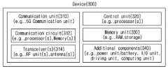
- a wireless device 300corresponds to the wireless devices 200a and 200b of FIG. 2 , and includes various elements, components, units/units, and/or modules. ) can be composed of
- the wireless device 300may include a communication unit 310 , a control unit 320 , a memory unit 330 , and an additional element 340 .
- the communication unitmay include communication circuitry 312 and transceiver(s) 314 .
- communication circuitry 312may include one or more processors 202a, 202b and/or one or more memories 204a, 204b of FIG. 2 .
- the transceiver(s) 314may include one or more transceivers 206a , 206b and/or one or more antennas 208a , 208b of FIG. 2 .
- the control unit 320is electrically connected to the communication unit 310 , the memory unit 330 , and the additional element 340 and controls general operations of the wireless device.
- the controller 320may control the electrical/mechanical operation of the wireless device based on the program/code/command/information stored in the memory unit 330 .
- control unit 320transmits the information stored in the memory unit 330 to the outside (eg, another communication device) through the communication unit 310 through a wireless/wired interface, or externally (eg, through the communication unit 310) Information received through a wireless/wired interface from another communication device) may be stored in the memory unit 330 .
- the additional element 340may be configured in various ways according to the type of the wireless device.
- the additional element 340may include at least one of a power unit/battery, an input/output unit, a driving unit, and a computing unit.
- the wireless device 300may include a robot ( FIGS. 1 and 100a ), a vehicle ( FIGS. 1 , 100b-1 , 100b-2 ), an XR device ( FIGS. 1 and 100c ), and a mobile device ( FIGS. 1 and 100d ). ), home appliances (FIG. 1, 100e), IoT device (FIG.
- the wireless devicemay be mobile or used in a fixed location depending on the use-example/service.
- various elements, components, units/units, and/or modules in the wireless device 300may be all interconnected through a wired interface, or at least some may be wirelessly connected through the communication unit 310 .
- the control unit 320 and the communication unit 310are connected by wire, and the control unit 320 and the first unit (eg, 130 , 140 ) are connected wirelessly through the communication unit 310 .
- each element, component, unit/unit, and/or module within the wireless device 300may further include one or more elements.
- the controller 320may include one or more processor sets.
- control unit 320may be configured as a set of a communication control processor, an application processor, an electronic control unit (ECU), a graphic processing processor, a memory control processor, and the like.
- memory unit 330may include RAM, dynamic RAM (DRAM), ROM, flash memory, volatile memory, non-volatile memory, and/or a combination thereof. can be configured.
- FIG. 4is a diagram illustrating an example of a mobile device applied to the present disclosure.
- the portable devicemay include a smart phone, a smart pad, a wearable device (eg, a smart watch, smart glasses), and a portable computer (eg, a laptop computer).
- the mobile devicemay be referred to as a mobile station (MS), a user terminal (UT), a mobile subscriber station (MSS), a subscriber station (SS), an advanced mobile station (AMS), or a wireless terminal (WT).
- MSmobile station
- UTuser terminal
- MSSmobile subscriber station
- SSsubscriber station
- AMSadvanced mobile station
- WTwireless terminal
- the communication unit 410may transmit and receive signals (eg, data, control signals, etc.) with other wireless devices and base stations.
- the controller 420may control components of the portable device 400 to perform various operations.
- the controller 420may include an application processor (AP).
- the memory unit 430may store data/parameters/programs/codes/commands necessary for driving the portable device 400 . Also, the memory unit 430 may store input/output data/information.
- the power supply unit 440asupplies power to the portable device 400 and may include a wired/wireless charging circuit, a battery, and the like.
- the interface unit 440bmay support a connection between the portable device 400 and other external devices.
- the interface unit 440bmay include various ports (eg, an audio input/output port and a video input/output port) for connection with an external device.
- the input/output unit 440cmay receive or output image information/signal, audio information/signal, data, and/or information input from a user.
- the input/output unit 440cmay include a camera, a microphone, a user input unit, a display unit 440d, a speaker, and/or a haptic module.
- the input/output unit 440cobtains information/signals (eg, touch, text, voice, image, video) input from the user, and the obtained information/signals are stored in the memory unit 430 . can be saved.
- the communication unit 410may convert the information/signal stored in the memory into a wireless signal, and transmit the converted wireless signal directly to another wireless device or to a base station. Also, after receiving a radio signal from another radio device or base station, the communication unit 410 may restore the received radio signal to original information/signal.
- the restored information/signalmay be stored in the memory unit 430 and output in various forms (eg, text, voice, image, video, haptic) through the input/output unit 440c.
- FIG. 5is a diagram illustrating an example of a vehicle or autonomous driving vehicle applied to the present disclosure.
- the vehicle or autonomous driving vehiclemay be implemented as a mobile robot, a vehicle, a train, an aerial vehicle (AV), a ship, and the like, but is not limited to the shape of the vehicle.
- AVaerial vehicle
- the vehicle or autonomous driving vehicle 500includes an antenna unit 508 , a communication unit 510 , a control unit 520 , a driving unit 540a , a power supply unit 540b , a sensor unit 540c and autonomous driving.
- a unit 540dmay be included.
- the antenna unit 550may be configured as a part of the communication unit 510 .
- Blocks 510/530/540a to 540drespectively correspond to blocks 410/430/440 of FIG. 4 .
- the communication unit 510may transmit/receive signals (eg, data, control signals, etc.) to and from external devices such as other vehicles, base stations (eg, base stations, roadside units, etc.), and servers.
- the controller 520may control elements of the vehicle or the autonomous driving vehicle 500 to perform various operations.
- the controller 520may include an electronic control unit (ECU).
- ECUelectronice control unit
- AI devicesinclude TVs, projectors, smartphones, PCs, laptops, digital broadcasting terminals, tablet PCs, wearable devices, set-top boxes (STBs), radios, washing machines, refrigerators, digital signage, robots, vehicles, etc. It may be implemented as a device or a mobile device.
- the AI device 900includes a communication unit 910 , a control unit 920 , a memory unit 930 , input/output units 940a/940b , a learning processor unit 940c and a sensor unit 940d.
- the communication unit 910uses wired/wireless communication technology to communicate with external devices such as other AI devices (eg, FIGS. 1, 100x, 120, 140) or an AI server ( FIGS. 1 and 140 ) and wired/wireless signals (eg, sensor information, user input, learning model, control signal, etc.). To this end, the communication unit 910 may transmit information in the memory unit 930 to an external device or transmit a signal received from the external device to the memory unit 930 .
- AI deviceseg, FIGS. 1, 100x, 120, 140
- an AI serverFIGS. 1 and 140
- wired/wireless signalseg, sensor information, user input, learning model, control signal, etc.
- the controller 920may determine at least one executable operation of the AI device 900 based on information determined or generated using a data analysis algorithm or a machine learning algorithm. In addition, the controller 920 may control the components of the AI device 900 to perform the determined operation. For example, the control unit 920 may request, search, receive, or utilize the data of the learning processor unit 940c or the memory unit 930, and may be a predicted operation among at least one executable operation or determined to be preferable. Components of the AI device 900 may be controlled to execute the operation.
- control unit 920collects history information including user feedback on the operation contents or operation of the AI device 900 and stores it in the memory unit 930 or the learning processor unit 940c, or the AI server ( 1 and 140), and the like may be transmitted to an external device.
- the collected historical informationmay be used to update the learning model.
- the memory unit 930may store data supporting various functions of the AI device 900 .
- the memory unit 930may store data obtained from the input unit 940a , data obtained from the communication unit 910 , output data of the learning processor unit 940c , and data obtained from the sensing unit 940 .
- the memory unit 930may store control information and/or software codes necessary for the operation/execution of the control unit 920 .
- the input unit 940amay acquire various types of data from the outside of the AI device 900 .
- the input unit 920may obtain training data for model learning, input data to which the learning model is applied, and the like.
- the input unit 940amay include a camera, a microphone, and/or a user input unit.
- the output unit 940bmay generate an output related to sight, hearing, or touch.
- the output unit 940bmay include a display unit, a speaker, and/or a haptic module.
- the sensing unit 940may obtain at least one of internal information of the AI device 900 , surrounding environment information of the AI device 900 , and user information by using various sensors.
- the sensing unit 940may include a proximity sensor, an illumination sensor, an acceleration sensor, a magnetic sensor, a gyro sensor, an inertial sensor, an RGB sensor, an IR sensor, a fingerprint recognition sensor, an ultrasonic sensor, an optical sensor, a microphone, and/or a radar. there is.
- the learning processor unit 940cmay train a model composed of an artificial neural network by using the training data.
- the learning processor unit 940cmay perform AI processing together with the learning processor unit of the AI server ( FIGS. 1 and 140 ).
- the learning processor unit 940cmay process information received from an external device through the communication unit 910 and/or information stored in the memory unit 930 . Also, the output value of the learning processor unit 940c may be transmitted to an external device through the communication unit 910 and/or stored in the memory unit 930 .
- the transmission signalmay be processed by a signal processing circuit.
- the signal processing circuit 1200may include a scrambler 1210 , a modulator 1220 , a layer mapper 1230 , a precoder 1240 , a resource mapper 1250 , and a signal generator 1260 .
- the operation/function of FIG. 7may be performed by the processors 202a and 202b and/or the transceivers 206a and 206b of FIG. 2 .
- blocks 1010 to 1060may be implemented in the processors 202a and 202b of FIG. 2 .
- blocks 1210 to 1250may be implemented in the processors 202a and 202b of FIG. 2
- block 1260may be implemented in the transceivers 206a and 206b of FIG. 2 , and the embodiment is not limited thereto.
- the codewordmay be converted into a wireless signal through the signal processing circuit 1200 of FIG. 7 .
- the codewordis a coded bit sequence of an information block.
- the information blockmay include a transport block (eg, a UL-SCH transport block, a DL-SCH transport block).
- the radio signalmay be transmitted through various physical channels (eg, PUSCH, PDSCH).
- the codewordmay be converted into a scrambled bit sequence by the scrambler 1210 .
- a scramble sequence used for scramblingis generated based on an initialization value, and the initialization value may include ID information of a wireless device, and the like.
- the scrambled bit sequencemay be modulated by a modulator 1220 into a modulation symbol sequence.
- the modulation methodmay include pi/2-binary phase shift keying (pi/2-BPSK), m-phase shift keying (m-PSK), m-quadrature amplitude modulation (m-QAM), and the like.
- the complex modulation symbol sequencemay be mapped to one or more transport layers by a layer mapper 1230 .
- Modulation symbols of each transport layermay be mapped to corresponding antenna port(s) by the precoder 1240 (precoding).
- the output z of the precoder 1240may be obtained by multiplying the output y of the layer mapper 1230 by the precoding matrix W of N*M.
- Nis the number of antenna ports
- Mis the number of transmission layers.
- the precoder 1240may perform precoding after performing transform precoding (eg, discrete fourier transform (DFT) transform) on the complex modulation symbols. Also, the precoder 1240 may perform precoding without performing transform precoding.
- transform precodingeg, discrete fourier transform (DFT) transform
- the resource mapper 1250may map modulation symbols of each antenna port to a time-frequency resource.
- the time-frequency resourcemay include a plurality of symbols (eg, a CP-OFDMA symbol, a DFT-s-OFDMA symbol) in the time domain and a plurality of subcarriers in the frequency domain.
- the signal generator 1260generates a radio signal from the mapped modulation symbols, and the generated radio signal may be transmitted to another device through each antenna.
- the signal generator 1260may include an inverse fast fourier transform (IFFT) module and a cyclic prefix (CP) inserter, a digital-to-analog converter (DAC), a frequency uplink converter, and the like. .
- IFFTinverse fast fourier transform
- CPcyclic prefix
- DACdigital-to-analog converter
- the signal processing process for the received signal in the wireless devicemay be configured in reverse of the signal processing process 1210 to 1260 of FIG. 7 .
- the wireless deviceeg, 200a or 200b of FIG. 2
- the received radio signalmay be converted into a baseband signal through a signal restorer.
- the signal restorermay include a frequency downlink converter, an analog-to-digital converter (ADC), a CP remover, and a fast fourier transform (FFT) module.
- ADCanalog-to-digital converter
- FFTfast fourier transform
- the baseband signalmay be restored to a codeword through a resource de-mapper process, a postcoding process, a demodulation process, and a descrambling process.
- the codewordmay be restored to the original information block through decoding.
- the signal processing circuit (not shown) for the received signalmay include a signal restorer, a resource de-mapper, a post coder, a demodulator, a descrambler, and a decoder.
- 6G (wireless) systemshave (i) very high data rates per device, (ii) very large number of connected devices, (iii) global connectivity, (iv) very low latency, (v) battery- It aims to reduce energy consumption of battery-free IoT devices, (vi) ultra-reliable connections, and (vii) connected intelligence with machine learning capabilities.
- the vision of the 6G systemmay have four aspects such as “intelligent connectivity”, “deep connectivity”, “holographic connectivity”, and “ubiquitous connectivity”, and the 6G system can satisfy the requirements shown in Table 1 below. That is, Table 1 is a table showing the requirements of the 6G system.
- the 6G systemincludes enhanced mobile broadband (eMBB), ultra-reliable low latency communications (URLLC), massive machine type communications (mmTC), AI integrated communication, and tactile Internet (tactile internet), high throughput (high throughput), high network capacity (high network capacity), high energy efficiency (high energy efficiency), low backhaul and access network congestion (low backhaul and access network congestion) and improved data security ( It may have key factors such as enhanced data security.
- eMBBenhanced mobile broadband
- URLLCultra-reliable low latency communications
- mmTCmassive machine type communications
- AI integrated communicatione.g., eMBB
- tactile Internete internet
- high throughputhigh network capacity
- high energy efficiencyhigh energy efficiency
- low backhaul and access network congestionlow backhaul and access network congestion
- improved data securityIt may have key factors such as enhanced data security.
- FIG. 10is a diagram illustrating an example of a communication structure that can be provided in a 6G system applicable to the present disclosure.
- the 6G systemis expected to have 50 times higher simultaneous wireless communication connectivity than the 5G wireless communication system.
- URLLCa key feature of 5G, is expected to become an even more important technology by providing an end-to-end delay of less than 1 ms in 6G communication.
- the 6G systemwill have much better volumetric spectral efficiency, unlike the frequently used area spectral efficiency.
- 6G systemscan provide very long battery life and advanced battery technology for energy harvesting, so mobile devices in 6G systems may not need to be charged separately.
- AIThe most important and newly introduced technology for 6G systems is AI.
- AIwas not involved in the 4G system.
- 5G systemswill support partial or very limited AI.
- the 6G systemwill be AI-enabled for full automation.
- Advances in machine learningwill create more intelligent networks for real-time communication in 6G.
- Incorporating AI into communicationscan simplify and enhance real-time data transmission.
- AIcan use numerous analytics to determine how complex target tasks are performed. In other words, AI can increase efficiency and reduce processing delays.
- AIcan also play an important role in M2M, machine-to-human and human-to-machine communication.
- AIcan be a rapid communication in the BCI (brain computer interface).
- BCIbrain computer interface
- AI-based communication systemscan be supported by metamaterials, intelligent structures, intelligent networks, intelligent devices, intelligent cognitive radios, self-sustaining wireless networks, and machine learning.
- AI-based physical layer transmissionmeans applying a signal processing and communication mechanism based on an AI driver rather than a traditional communication framework in a fundamental signal processing and communication mechanism.
- a signal processing and communication mechanismbased on an AI driver rather than a traditional communication framework in a fundamental signal processing and communication mechanism.
- deep learning-based channel coding and decoding, deep learning-based signal estimation and detection, deep learning-based multiple input multiple output (MIMO) mechanismIt may include AI-based resource scheduling and allocation.
- Machine learningmay be used for channel estimation and channel tracking, and may be used for power allocation, interference cancellation, and the like in a physical layer of a downlink (DL). In addition, machine learning may be used for antenna selection, power control, symbol detection, and the like in a MIMO system.
- DLdownlink
- machine learningmay be used for antenna selection, power control, symbol detection, and the like in a MIMO system.
- Deep learning-based AI algorithmsrequire large amounts of training data to optimize training parameters.
- a lot of training datais used offline. This is because static training on training data in a specific channel environment may cause a contradiction between dynamic characteristics and diversity of a wireless channel.
- signals of the physical layer of wireless communicationare complex signals.
- further research on a neural network for detecting a complex domain signalis needed.
- Machine learningrefers to a set of operations that trains a machine to create a machine that can perform tasks that humans can or cannot do.
- Machine learningrequires data and a learning model.
- data learning methodscan be roughly divided into three types: supervised learning, unsupervised learning, and reinforcement learning.
- Neural network learningis to minimize output errors. Neural network learning repeatedly inputs learning data into the neural network, calculates the output and target errors of the neural network for the training data, and backpropagates the neural network error from the output layer of the neural network to the input layer in the direction to reduce the error. ) to update the weight of each node in the neural network.
- Supervised learninguses training data in which the correct answer is labeled in the training data, and in unsupervised learning, the correct answer may not be labeled in the training data. That is, for example, learning data in the case of supervised learning related to data classification may be data in which categories are labeled for each of the training data.
- the labeled training datais input to the neural network, and an error can be calculated by comparing the output (category) of the neural network with the label of the training data.
- the calculated erroris back propagated in the reverse direction (ie, from the output layer to the input layer) in the neural network, and the connection weight of each node of each layer of the neural network may be updated according to the back propagation.
- the change amount of the connection weight of each node to be updatedmay be determined according to a learning rate.
- the computation of the neural network on the input data and the backpropagation of errorscan constitute a learning cycle (epoch).
- the learning ratemay be applied differently depending on the number of repetitions of the learning cycle of the neural network. For example, in the early stage of learning a neural network, a high learning rate can be used to increase the efficiency by allowing the neural network to quickly obtain a certain level of performance, and in the late learning period, a low learning rate can be used to increase the accuracy.
- the learning methodmay vary depending on the characteristics of the data. For example, when the purpose of accurately predicting data transmitted from a transmitter in a communication system is at a receiver, it is preferable to perform learning using supervised learning rather than unsupervised learning or reinforcement learning.
- the learning modelcorresponds to the human brain, and the most basic linear model can be considered. ) is called
- the neural network cord used as a learning methodis largely divided into deep neural networks (DNN), convolutional deep neural networks (CNN), and recurrent boltzmann machine (RNN) methods. and such a learning model can be applied.
- DNNdeep neural networks
- CNNconvolutional deep neural networks
- RNNrecurrent boltzmann machine
- THz communicationmay be applied in the 6G system.
- the data ratemay be increased by increasing the bandwidth. This can be accomplished by using sub-THz communication with a wide bandwidth and applying advanced large-scale MIMO technology.
- a THz wavealso known as sub-millimeter radiation, generally represents a frequency band between 0.1 THz and 10 THz with a corresponding wavelength in the range of 0.03 mm-3 mm.
- the 100GHz-300GHz band range(Sub THz band) is considered a major part of the THz band for cellular communication.
- Sub-THz bandAddition to mmWave band increases 6G cellular communication capacity.
- 300GHz-3THzis in the far-infrared (IR) frequency band.
- the 300GHz-3THz bandis part of the broadband, but at the edge of the wideband, just behind the RF band. Therefore, this 300 GHz - 3 THz band shows similarity to RF.
- THz communicationThe main characteristics of THz communication include (i) widely available bandwidth to support very high data rates, and (ii) high path loss occurring at high frequencies (high directional antennas are indispensable).
- the narrow beamwidth produced by the highly directional antennareduces interference.
- the small wavelength of the THz signalallows a much larger number of antenna elements to be integrated into devices and BSs operating in this band. This allows the use of advanced adaptive nesting techniques that can overcome range limitations.
- FIG. 10is a diagram illustrating a THz communication method applicable to the present disclosure.
- THz waveis located between RF (Radio Frequency)/millimeter (mm) and infrared band, (i) It transmits non-metal/non-polar material better than visible light/infrared light, and has a shorter wavelength than RF/millimeter wave, so it has high straightness. Beam focusing may be possible.
- FIG. 11is a diagram illustrating a neural network applicable to the present disclosure.
- artificial intelligence technologymay be introduced in a new communication system (e.g. 6G system).
- artificial intelligencecan utilize a neural network as a machine learning model modeled after the human brain.
- the devicemay process the arithmetic operation consisting of 0 and 1, and may perform operations and communication based on this.
- the devicecan process many arithmetic operations in a faster time and using less power than before.
- humanscannot perform arithmetic operations as fast as devices.
- the human brainmay not be built to process only fast arithmetic operations.
- humanscan perform operations such as recognition and natural language processing.
- the above-described operationis an operation for processing something more than arithmetic operation, and the current device may not be able to process to a level that a human brain can do. Therefore, it may be considered to make a system so that the device can achieve performance similar to that of a human in areas such as natural language processing and computer vision.
- the neural networkmay be a model created based on the idea of mimicking the human brain.
- the neural networkmay be a simple mathematical model made with the above-described motivation.
- the human braincan consist of a huge number of neurons and synapses connecting them.
- an actionmay be taken by selecting whether other neurons are also activated.
- the neural networkmay define a mathematical model based on the above facts.
- neuronsare nodes, and it may be possible to create a network in which a synapse connecting neurons is an edge.
- the importance of each synapsemay be different. That is, it is necessary to separately define a weight for each edge.
- the neural networkmay be a directed graph. That is, information propagation may be fixed in one direction. For example, when a non-directed edge is provided or the same direct edge is given in both directions, information propagation may occur recursively. Therefore, the result by the neural network can be complicated.
- the neural network as described abovemay be a recurrent neural network (RNN). At this time, since RNN has the effect of storing past data, it is recently used a lot when processing sequential data such as voice recognition.
- the multi-layer perceptron (MLP) structuremay be a directed simple graph.
- the MLPmay be the above-described MLP unless there is a special mention of the layer below, but the present invention is not limited thereto.
- the above-described networkmay be a feed-forward network, but is not limited thereto.
- different neuronsmay be activated in an actual brain, and the result may be transmitted to the next neuron.
- the result valuecan be activated by the neuron that makes the final decision, and the information is processed through it.
- the above-described methodis changed to a mathematical model, it may be possible to express an activation condition for input data as a function.
- the above-described functionmay be referred to as an activate function.
- the simplest activation functionmay be a function that sums all input data and compares it with a threshold value. For example, when the sum of all input data exceeds a specific value, the device may process information as activation. On the other hand, when the sum of all input data does not exceed a specific value, the device may process information as deactivation.
- the activation functionmay have various forms.
- Equation 1may be defined for convenience of description. In this case, in Equation 1, it is necessary to consider not only the weight w but also the bias, and when this is taken into consideration, it can be expressed as Equation 2 below. However, since the vise (b) and the weight (w) are almost the same, only the weight is considered and described below. However, the present invention is not limited thereto. For example, if x0 having a value of 1 is always added, w0 becomes a vise, so a virtual input can be assumed and the weight and the vise can be treated the same through this, and the embodiment is not limited thereto.
- a model based on the abovecan initially define the shape of a network composed of nodes and edges. After that, the model can define an activation function for each node.
- the role of the parameter that adjusts the modeltakes on the weight of the edge, and finding the most appropriate weight may be a training goal of the mathematical model.
- the following Equations 3 to 6may be one form of the above-described activation function, and are not limited to a specific form.
- the neural networkmay first determine activation of the next layer with respect to a given input, and may determine activation of the next layer according to the determined activation. Based on the above-described method, the interface may be determined by looking at the result of the last decision layer.
- FIG. 12is a diagram illustrating an activation node in a neural network applicable to the present disclosure.
- FIG. 12when classification is performed, as many decision nodes as the number of classes to be classified in the last layer are created, and then one of them is activated to select a value.
- a case in which activation functions of a neural network are non-linear and the functions are complexly configured while forming layers with each othermay be considered.
- weight optimization of the neural networkmay be non-convex optimization. Therefore, it may be impossible to find a global optimization of parameters of a neural network.
- a method of convergence to an appropriate value using a gradient descent methodmay be used. For example, all optimization problems can be solved only when a target function is defined.
- a method of minimizing a corresponding value by calculating a loss function between a target output actually desired in the final decision layer and an estimated output generated by the current networkmay be calculated.
- the loss functionmay be as shown in Equations 7 to 9 below, but is not limited thereto.
- Equations 7 to 9may be loss functions for optimization.
- the back propagation algorithmmay be an algorithm capable of simply performing gradient calculation using a chain rule.
- parallelizationmay also be easy.
- memorycan be saved through algorithm design. Therefore, the neural network update may use a backpropagation algorithm.
- the backpropagation algorithma loss is first calculated using the current parameters, and how much each parameter affects the corresponding loss can be calculated through the chain rule. An update may be performed based on the calculated value.
- the backpropagation algorithmmay be divided into two phases.
- Onemay be a propagation phase, and the other may be a weight update phase.
- an error or a change amount of each neuronmay be calculated from a training input pattern.
- the weightin the weight update phase, the weight may be updated using the previously calculated value.
- specific phasesmay be as shown in Table 2 below.
- an autoencoder methodmay be applied as a channel coding method.
- the auto encoderconfigures both the transmitter and the receiver as a neural network, and performs optimization from an end-to-end perspective to improve performance.
- method, and channel codingmay be performed based on an auto-encoder.
- channel coding in a wireless communication systemmay be essential to ensure reliable transmission.
- the channel codingmay enable reliable communication by restoring the original signal through redundant information when an error occurs due to an external factor such as noise during a signal transmission process between the transmitter and the receiver.
- the code rate of the transmission signalmay be determined according to the ratio of the additional information. For example, for reliable transmission, a coding scheme having higher error correction capability with respect to code efficiency may be required.
- a wireless communication systeme.g. NR
- data transmission/receptionmay be performed by applying a polar coding scheme using a channel polarity.
- the polar coding schemecan achieve channel capacity in a basic communication channel situation when the block size becomes longer by using the channel polarity.
- at least one of performance, color noise, fading loss, and reception/decoding complexitymay occur in a short block length in a short block length.
- a channel coding schemethat solves the above-mentioned problems of polar coding may be required to ensure reliable transmission, which will be described below.
- FIG. 13is a diagram illustrating a neural network-based communication system applicable to the present disclosure.
- communicationmay be performed based on a neural network (or a neural net).
- datamay be transmitted/received based on the auto-encoder method as a neural network-based communication.
- communicationis performed through a transmitter neural net (or a transmitter neural network, 1320) and a receiver neural network (or a receiver neural network, 1340). can do.
- the binary information signal sequence ( )is the target signal sequence ( ) can be converted to
- the one-hot transformation unit 1310may be configured to perform transformation in order to apply data such as natural language to the neural network.
- the one-hot conversion unit 1310may also operate based on other conversion units, and is not limited to the above-described embodiment.
- the neural net 1320 of the transmittertransmits the target signal sequence ( ) to transmit the transmission signal sequence ( ), and at the transmitting end, the transmission signal sequence ( ) may be transmitted to the receiving end through the wireless channel 1330 .
- the receiving endtransmits the received signal sequence ( ) to the decoded signal sequence ( ) can be obtained. That is, the receiving end may receive a signal sequence including an influence on the channel environment, such as fading distortion and noise, based on the wireless channel 1330 .
- the decoded signal sequence ( )is a binary decoded signal sequence ( ) can be converted to That is, the target signal sequence ( ) and the decoded signal sequence ( ) is the binary information signal sequence ( ) and the binary decoded signal sequence ( ) may be transformed into a one-hot vector in consideration of neural net application. Therefore, a binary information signal sequence of length K is It can be a one-hot vector of length.
- the decoded signal sequence of lengthmay be a binary decoded signal sequence of length L. That is, as the length K of the information increases, the data converted into the one-hot vector increases exponentially, so there may be a limit in a block having a large length.
- the target signal sequence of the transmitter ( ) and the transmission signal sequence ( )is the same as Equation 10 below, and the decoded signal sequence ( ) and the received signal sequence ( ) may be the same as in Equation 11 below.
- the transmitter neural net 1320may be expressed as Equation 12 below.
- H and Mmay be the number of nodes in the input layer, the hidden layer, and the output layer, respectively.
- the receiver neural net 1340may be expressed as in Equation 13 below.
- x 1may be a real vector.
- M, Hmay be the number of nodes in the input layer, the hidden layer, and the output layer, respectively. Also, the number of nodes in the output layer may be equal to the length of the target signal sequence.
- the entire channel codingmay be performed based on the neural net.
- the learning of the transmitting neural net and the receiving neural netmay be complicated in proportion to the exponential. More specifically, both the length of the number of input nodes of the transmitting neural net and the number of output nodes of the receiving neural net, which are related to the learning complexity in the autoencoder, are As such, it can be increased in proportion to the exponent of K, which is the size of the information signal sequence. Therefore, when the size of the binary information sequence increases, the learning of the transmitting neural net and the receiving neural net may be complicated in proportion to the exponential.
- a long coding blockmay be required to achieve high coding performance.
- learning of neurallet-based channel codingmay become difficult due to increased complexity.
- a new neural channel coding methodcapable of code processing for a long block with a length that can be performed by existing channel coding while maintaining the advantages of channel situation adaptability and relatively low decoding complexity may be required. and will be described below.
- the binary information signal sequence skis transmitted through the polar encoder 1410 , the modulator 1420 , and the transmission signal processing unit 1430 at the transmitting end. ) can be changed to After that, the transmission signal sequence ( ) may be transmitted to the receiving end through the wireless channel 1440 . At this time, the receiving end transmits the received signal sequence ( ) through the reception signal processing unit 1450, the demodulator 1460 and the polar decoder 1470, ) can be obtained.
- an encoding procedure based on the polar encoder 1410 at the transmitting endmay be as shown in FIG. 15 .
- polar codingmay be a method in which a channel capacity achievement rate is increased.
- a binary information signal sequence of length K ( )the polar encoder 1410 generates a polar input signal sequence of length N ( ) is created, polar transformation may be performed, and the transformed values may be output as an encoding result.
- k indexwhich is a time element, may be omitted, and may be expressed as in Equation 14 below.
- the length of the code blockis case can be considered. That is, if n is 2, the polar transition matrix may be configured as in Equation 16 below.
- Fig. 15(a)is a case in which the indices of input/output variables are arranged in a general descending order
- Fig. 15(b)is an input operation process that is arranged through a reverse bit order process to indicate the opposite (1, 3, 2, The index can be indicated as in 4).
- FIG. 15can be
- FIG. 16is It is a diagram showing a case where More specifically, In the case of , it can be expressed as in Equation 17 by applying a polar transformation matrix.
- FIGS. 16 (a) and 16 (b)are It may be a drawing showing a case where .
- FIG. 16(a)is a case in which the indexes of input/output variables are arranged in a general descending order
- FIG. 16(b)may be a case in which the indices of the input/output variables are arranged through a reverse bit order process to indicate the opposite of the input operation process.
- 17is a diagram illustrating a decoding method based on polar coding applicable to the present disclosure.
- a receiving endmay receive a signal encoded based on a polar code and decode the signal.
- the encoding of the polar codemay be in a form based on repetition of the same pattern, and the decoding is also in the form of repetition of a process of processing two received bits.
- Decodingmay be performed based on the block size.
- the receiving endreceives from the radio channel for 2T and signal can be received.
- thisis only one example and is not limited to the above-described embodiment.
- the radio channelmay affect the signal according to the channel environment like the aforementioned fading or noise.
- the received signal based on the radio channeland may be as in Equation 18 below.
- nis the mean 0 and variance is a phosphorus back-added noise (AWGN) signal, may be a signal-to-noise ratio (SNR).
- SNRsignal-to-noise ratio
- the polar decoder first, which is the Log Likelihood Ratio (LLR) for and may be derived based on Equations 19 and 20 below.
- Equations 21 and 22When derived based on Equations 19 and 20, the LLR output for the two branches is and can be given as in Equations 21 and 22.
- Equation 21may be the same as Equation 23 below, and the g() function of Equation 22 may be equal to Equation 24 below.
- U1 of the g() function of Equation 24is It may be a result of determining the value as ⁇ 0,1 ⁇ after calculating , and polar decoding may be performed based on the above description. That is, the decoding of the polo code may be derived based on the LLR, as described above.
- a polar code using a channel polaritymay be advantageous for a long block.
- the learning complexitydepends on the bit of the transmission sequence. , so autoencoders can be advantageous for short blocks. More specifically, the polar code operates even when the coding block size is long, but the performance limitations of channel coding are limited in various non-basic situations, i.e., performance at a short block length, color noise, fading loss, and low-complexity reception situations. may exist.
- the auto encoder methoduses the neural net of the transmitting and receiving end, it is possible to simultaneously optimize modulation, signal processing, and coding, as well as reduce the complexity of processing at the receiving end.
- the coding block sizeis long, since the size of the neural net input increases exponentially, there may be a disadvantage in that it is very difficult to learn.
- an effective method for performing channel coding by combining a polar code and an auto-encoder transmission method as a channel coding methodmay be required, which will be described below.
- FIG. 18is a diagram illustrating a method of performing polar transformation based on partial polar coding applicable to the present disclosure.
- the polar code schemeis applied for coding between relatively distant codes, and the auto-encoder coded neural net scheme is used for coding adjacent codes. configurable.
- the polar code methodis applied to coding between codes separated by a preset distance
- the auto-encoder methodis applied to coding between codes adjacent within a preset distance to perform environment optimization.
- the channel coding method in which the auto encoder and the polar code method are combinedmay be a neural polar code encoding method, but is not limited to the above-mentioned name. That is, a channel coding scheme using a combination of a polar code and an auto-encoder scheme may be used under a different name, and may not be limited to a specific name. However, in the description, for convenience of description, it is referred to as a neural polar code.
- pre-processingmay be performed at an internal front end of the auto-encoder to which a binary input is input as an input of the auto-encoder.
- the preprocessing processmay be a process of changing a binary input based on a one-hot vector, but may not be limited thereto.
- the output of the auto encodermay be BPSK (Binary Phase Shift Keying), and the coding rate may be 1.
- BPSKBinary Phase Shift Keying
- X', Z', and U'may be factors rearranged in the reverse bit order of X, Z, and U.
- Equation 26Transformation by can be defined as partial polar transformation.
- the required number of auto-encoders Mmay be 2.
- the neural polar codemay be applied based on Equations 27, 28 and 29 below based on Equations 25 and 26 described above to generate an encoded signal.
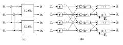
- a polar codemay be applied to non-adjacent bits of U bits, and an auto-encoder may be applied to adjacent bits, and in consideration of this, FIG. 19(a)
- Each of the bits of Ucan be adjusted as
- each layermay exist in the neural polar code, and whether the polar code and the auto-encoder are applied may be determined based on layer information. More specifically, FIG. 19(b) may consist of two layers based on an auto-encoder having an adjacent number of bits K.
- a polar codemay be applied to bits that are not adjacent to each other.
- the output bit of the first layermay be the input bit of the second layer, and the second layer may be replaced by the auto-encoder layer in the polar code based on the number of adjacent bits K of the auto-encoder.
- the degree of freedom of learningis increased, but there may be a limit to learning convergence due to an increase in input.
- the auto-encoderis applied only to the last one layer and divided into three layers.
- the auto-encodermay have the same structure as the existing polar code. That is, a layer to which the auto-encoder is applied in the neural polar code may be selected differently, and may not be limited to a specific form.
- layer information to which the auto encoder is appliedmay be shared between the transmitter and the receiver.
- the terminal and the base stationmay share layer information to which the auto encoder is applied.
- the layer informationmay be set based on the number of adjacent bits of the auto encoder.
- the terminal and the base stationmay exchange candidate neighbor bit information of the auto-encoder through higher layer signaling.
- candidate adjacent bitsmay be determined in consideration of learning complexity.
- the base stationmay transmit specific adjacent bit information among the candidate adjacent bits to the terminal through downlink control information (DCI), and the terminal may perform channel coding based on the received information.
- DCIdownlink control information
- the layer to which the auto-encoder is applied in the neural polar codemay be preset and not changed in the process of performing the initial access.
- the base stationmay indicate the above-described K value through DCI without a candidate adjacent bit, and the terminal may identify a layer to which the auto-encoder is applied based on DCI information, and is not limited to the above-described embodiment.
- the layer to which the auto-encoder is appliedmay be preset or it may be flexibly changed, and the transmitting end and the receiving end may share information about the layer to which the auto-encoder is applied, thereby improving channel coding efficiency.
- FIG. 20is a diagram illustrating a case in which only one auto-encoder is used in order to reduce the learning complexity of the transmitting end.
- M (N/K) auto-encodersmay be used based on the number of adjacent bits K and the entire bit stream N.
- the neural polar codemay be used as one auto-encoder input by time-dividing signals of coding blocks obtained by performing polar coding. That is, signals of coding blocks from which polar coding has been performed are temporally separated and applied to the auto-encoder, so that only one auto-encoder can be applied.
- the coding blocks from which polar coding is performedmay be temporally separated in consideration of the processing time of the signals, and through this, only one auto-encoder may be used.
- the autoencoderis As a result, it may be of a form in which encoding is carried out by fixing one Wow may be input separately based on time division, and other signals may also be input based on time division in the same manner.
- the transmitting endmay be able to perform channel coding using each of a plurality of auto-encoders in consideration of the low-latency operation, but in consideration of implementation complexity, based on the time division method using only one auto-encoder, as described above Transmission may be performed and is not limited to the above-described embodiment.
- the signal encoded through the neural polar codemay be transmitted from the transmitting end to the receiving end through a wireless channel.
- the receiving endmay perform decoding based on the neural polar code.
- the decoding methodmay be applicable to all encoding rates and is not limited to a specific embodiment.
- a receiving endmay decode a signal encoded with a neural polar code.
- decodingmay be performed in each node in a successive cancellation (SC) method based on the decoding neural net. More specifically, a case where N is 4 and K of AE is 2 may be considered in a code block length.
- SCsuccessive cancellation
- the decoding process based on the neural polar codemay use two f() and two g() defined in Equations 23 and 24, respectively.
- the f() functional neural netmay output two inputs and one bit-determined value
- the g() functional typemay output three inputs and one bit-determined value, and decoding is performed based on this.
- classmay be input to the 1st Tx-NN neural net.
- the neural netperforms encoding using the input and then returns the result. , can be output as In this case, the 1st Tx-NN neural net may assume the same input and output used in the corresponding step during learning, but may not be limited thereto.
- class Itcan be input to the 2nd Tx-NN neural net.
- the neural netperforms encoding using the corresponding input and then returns the result.
- the received signal ycan be received.
- the resultmay be applied to f() and g() as the above-described decoding process of the polar code to perform final decoding.
- Figure 21 (b), and may be neural nets for decoding at the receiving end.
- the RX-NN-f seriesmay refer to a neural net that processes without feedback cancellation
- the Rx-NN-g seriesmay refer to a neural net including feedback cancellation.
- ymay be a signal received at the receiving end after x passes through the radio channel.
- f()is class Signals received from the input can be determined and printed.
- g()a function based on three input bits, is class Each signal received from the the result as input can be determined and printed.
- Isis class The signal received from the the result as input.
- the corresponding resultcan be output as f() and g().
- f() and g()can be set to the same input and output used in the corresponding step even during learning, but may not be limited thereto.
- f() before classEach signal received from can be determined and printed.
- g()is class Each signal received from the the result as input can be determined and output, through which decoding can be performed at the receiving end.
- FIG. 22may also be a method of decoding a signal based on a neural polar code.
- the portion processed by the TX-NN based on the decoding neural net in each nodeis decoded in parallel, and the portion processed by the polar code is decoded by successive cancellation (SC) method for each Tx-NN part.
- SCsuccessive cancellation
- the code block length Nmay be 4 and the number of auto-encoders K may be 2.
- the decoding procedure in FIG. 22( a )may be the same as the decoding procedure in FIG. 21( a ). In this case, referring to FIG. 22( b ), neural net-based decoding may be performed.
- ymay be a signal received from the receiving end after x has passed through the radio channel.
- RX-NN-fimay perform the above-described neural net-based decoding, and the result may be applied to f() and g() as the above-described decoding process of the polar code to perform final decoding.
- Is , and the corresponding resultcan be output as f() and g().
- Is , and the corresponding resultcan be output as f() and g().
- classmay set the same input and output used in the corresponding step even during learning, but may not be limited thereto.
- f()is class Signals received from the input can be determined and printed.
- g()is class Each signal received from the the result as input can be determined and printed.
- f()takes the respective signals received from Rx-NN-f3 and Rx-NN-f4 previously as input and outputs the result. can be determined and printed.
- g( )is each signal received from Rx-NN-f3 and Rx-NN-f4 and the previously determined the result as input can be determined and output, through which the receiving end can perform decoding.
- FIG. 23is a diagram illustrating a decoding method based on a neural polar code.
- a portion processed by TX-NN based on the decoded neural net in each nodemay be processed by Rx-NN.
- the portion processed by the polar codemay be a case of decoding in a form compatible with the SC method.
- the code block length Nmay be 8 and the number of auto-encoders K may be 4, but may not be limited thereto.
- RX-NN-fi,j and RX-NN-gi,jcan perform decoding based on the above-described neural net, and the corresponding result is applied to f() and g() as the above-described decoding process of the polar code. and final decryption can be performed.
- xIt may be an encoding result signal.
- classmay be input to the 1st Tx-NN neural net.
- the corresponding neural netperforms encoding using the corresponding input and outputs the result.
- the 1st Tx-NN neural netmay be set to the same input and output used in the corresponding step even during learning, and is not limited to the above-described embodiment.
- the receiving endmay receive the y signal that has passed through the radio channel.
- f() and g()may be functions described in Equations 23 and 24.
- Wowmay be neural nets for decoding at the receiving end.
- i1, 2 and can be used repeatedly, and is not limited to a specific form.
- the RX-NN-f seriesmay refer to a neural net that processes without feedback cancellation
- the Rx-NN-g seriesmay refer to a neural net including feedback cancellation.
- silverand the corresponding result can be output as f() and g().
- Isand the corresponding result can be output as f() and g().
- classmay be set to the same input and output used in the corresponding step even during learning, and is not limited to the above-described embodiment.
- f()is class Signals received from the input can be determined and output.
- g()is class Each signal received from the the result as input can be determined and output.
- Is , and the corresponding resultcan be output as f() and g().
- Is , and the resultcan be output as f() and g().
- classmay be set to the same input and output used in the corresponding step even during learning, and is not limited to the above-described embodiment.
- f()is class Each signal received from the input can be determined and printed.
- g()is class Each signal received from the the result as input can be determined and printed. in other words, , , silver , and the result can be output as f() and g().
- Is , and the corresponding resultcan be output as f() and g().
- classmay be set to the same input and output used in the corresponding step even during learning, and is not limited to the above-described embodiment.
- f()is class signals received from the input, and the result can be determined and printed.
- g()is class Each signal received from the the result as input can be determined and printed.
- f() and g()can be output with f() and g().
- Is , and the resultcan be output to f() and g().
- classmay be set to the same input and output used in the corresponding step even during learning, and is not limited to the above-described embodiment.
- f()is class Each signal received from the input can be determined and printed
- g()is also class Each signal received from the the result as input can be determined and printed.
- 24is a diagram illustrating a method of performing encoding based on a neural polar code at a transmitting end.
- the transmitting endmay check layer information applied to the neural polar code.
- the transmitting endmay be a terminal, and the receiving end may be a base station.
- the transmitting endmay be a base station, and the receiving end may be a terminal.
- both the transmitting end and the receiving endmay be terminals, and the present invention is not limited to a specific case. However, in the following, for convenience of explanation, a case where the transmitting end is a terminal and the receiving end is a base station will be described.
- the layer informationmay be information on a layer to which a polar code transformation is applied in a neural polar code.
- polar code transformationmay be applied to bits of input data input to the neural polar code.
- polar code conversionmay be applied only to non-adjacent data among bits of the input data.
- polar code conversionmay be applied to bits separated by a preset distance among bits of input data. That is, the polar code conversion may be applied based on non-adjacent bits.
- encodingmay be performed on bits output through polar code conversion based on the auto-encoder.
- the layer to which the auto-encoder is applied in the neural polar codemay be the first layer. That is, after polar code transformation is applied to data bits, the layer to which the auto encoder is applied may be the first layer.
- the auto-encodermay input as many bits as the number of adjacent first bits.
- the auto-encodermay be configured to perform encoding through learning based on a neural net. For example, in neural net-based learning, when the block size increases, learning complexity may increase exponentially, and an auto-encoder may be applied from the first layer in consideration of the above points. Thereafter, encoding is performed based on the auto-encoder, and transmission data may be generated.
- the transmitting endmay transmit the transmission data to the receiving end through a wireless channel.
- Data input to the neural polar codemay consist of the second number of bits.
- the auto-encodersince the number of adjacent bits processed based on the auto-encoder may be the first number of bits, the auto-encoder may need as much as the number of dividing the second number of bits by the first number of bits.
- the transmittermay use only one auto-encoder.
- adjacent bits applied to the auto-encoder in the first layermay be distinguished based on a time division method. More specifically, the first group bits composed of the first number of bits in the first layer to which polar code transformation is applied are encoded through the one auto-encoder at a first time, and polar code transformation is applied to the first group in the first layer.
- a second group bit composed of one bitmay be encoded through one auto-encoder at a second time point. That is, the transmitter uses only one auto-encoder, and input bits to the auto-encoder are input separately in a time division manner, thereby reducing the terminal implementation complexity.
- the layer information applied to the neural polar codemay be information preset at the transmitting end and the receiving end.
- the transmitterreceives a reference signal from the receiver, performs channel measurement, transmits the measured channel information to the receiver, and then receives layer information applied to the neural polar code from the receiver through control information.
- the layer informationmay be variable information, and the transmitting end and the receiving end may use different layer information in consideration of the channel environment, and accordingly, the layer to which the auto-encoder is applied may be different.
- the layer to which the auto-encoder is appliedmay consist of index information, the receiving end transmits index information about the layer to the transmitting end based on the channel environment, and the transmitting end applies the auto-encoder based on the index information.
- datamay be encoded by applying only polar code transformation.
- the transmitting endencodes data only through polar code conversion and can perform transmission through a wireless channel, Examples are not limited.
- 25is a diagram illustrating a method of performing decoding based on a neural polar code at a receiving end.
- the receiving endmay receive transmitted data encoded based on the neural polar code through a wireless channel ( S2510 ). Thereafter, the receiving end performs decoding on the transmitted data received through the radio channel.
- the transmitting endmay be a terminal
- the receiving endmay be a base station.
- the transmitting endmay be a base station
- the receiving endmay be a terminal.
- both the transmitting end and the receiving endmay be terminals, and the present invention is not limited to a specific case. However, in the following, for convenience of explanation, a case where the transmitting end is a terminal and the receiving end is a base station will be described.
- the layer informationmay be information on a layer to which a polar code transformation is applied in a neural polar code.
- the receiving endsince the receiving end receives transmission data to which polar code conversion and auto-encoder are applied based on the neural polar code, it can perform neural net-based decoding and then polar code-based decoding, which is described in FIGS. 21 to 23 can be the same as
- an apparatusincluding at least one memory and at least one processor functionally connected to the one or more memories may be considered.
- the at least one processorenables the device to check layer information applied to the neural polar code, encode data input to the neural polar code based on the checked layer information to generate transmission data, and transmit the transmission data to the base station. can be controlled to transmit.
- the neural polar codeperforms encoding based on polar code transformation from the first layer of data to the first layer according to the checked layer information based on the polar code transformation, and after the first layer, the neural net until the transmission data is generated.
- Transmission datacan be generated by performing encoding through an underlying auto-encoder.
- a non-transitory computer-readable medium storing at least one instructionmay be considered.
- itincludes at least one instruction executable by the processor, and the at least one instruction is input as a neural polar code based on the device confirms layer information applied to the neural polar code and the checked layer information
- transmission datamay be generated by performing encoding through a neural net-based auto-encoder until transmission data is generated after the first layer, as described above.
- examples of the above-described proposed methodmay also be included as one of the implementation methods of the present disclosure, it is clear that they may be regarded as a kind of proposed method.
- the above-described proposed methodsmay be implemented independently, or may be implemented in the form of a combination (or merge) of some of the proposed methods.
- Rulescan be defined so that the base station informs the terminal of whether the proposed methods are applied or not (or information on the rules of the proposed methods) through a predefined signal (eg, a physical layer signal or a higher layer signal). there is.
- Embodiments of the present disclosuremay be applied to various wireless access systems.
- various radio access systemsthere is a 2nd Generation Partnership Project (3GPP) or a 3GPP2 system.
- 3GPP2nd Generation Partnership Project
- 3GPP23rd Generation Partnership Project2
- Embodiments of the present disclosuremay be applied not only to the various radio access systems, but also to all technical fields to which the various radio access systems are applied. Furthermore, the proposed method can be applied to mmWave and THzWave communication systems using very high frequency bands.
- embodiments of the present disclosuremay be applied to various applications such as free-running vehicles and drones.
Landscapes
- Engineering & Computer Science (AREA)
- Physics & Mathematics (AREA)
- Theoretical Computer Science (AREA)
- Probability & Statistics with Applications (AREA)
- General Health & Medical Sciences (AREA)
- Molecular Biology (AREA)
- Biophysics (AREA)
- Computational Linguistics (AREA)
- Data Mining & Analysis (AREA)
- Evolutionary Computation (AREA)
- Artificial Intelligence (AREA)
- Biomedical Technology (AREA)
- Computing Systems (AREA)
- General Engineering & Computer Science (AREA)
- General Physics & Mathematics (AREA)
- Mathematical Physics (AREA)
- Software Systems (AREA)
- Life Sciences & Earth Sciences (AREA)
- Health & Medical Sciences (AREA)
- Mobile Radio Communication Systems (AREA)
Abstract
Description
Translated fromKorean이하의 설명은 무선 통신 시스템에 대한 것으로, 무선 통신 시스템에서 단말 및 기지국이 채널 코딩을 수행하여 데이터를 송수신하는 방법 및 장치에 대한 것이다.The following description relates to a wireless communication system, and relates to a method and apparatus for transmitting and receiving data by performing channel coding by a terminal and a base station in a wireless communication system.
특히, 채널 코딩을 위해 폴라 코드(polar code)와 뉴럴넷(또는 신경망) 기반 채널 코딩 방식을 결합하는 방법 및 장치를 제공할 수 있다.In particular, it is possible to provide a method and apparatus for combining a polar code and a neural net (or neural network)-based channel coding scheme for channel coding.
무선 접속 시스템이 음성이나 데이터 등과 같은 다양한 종류의 통신 서비스를 제공하기 위해 광범위하게 전개되고 있다. 일반적으로 무선 접속 시스템은 가용한 시스템 자원(대역폭, 전송 파워 등)을 공유하여 다중 사용자와의 통신을 지원할 수 있는 다중 접속(multiple access) 시스템이다. 다중 접속 시스템의 예들로는 CDMA(code division multiple access) 시스템, FDMA(frequency division multiple access) 시스템, TDMA(time division multiple access) 시스템, OFDMA(orthogonal frequency division multiple access) 시스템, SC-FDMA(single carrier frequency division multiple access) 시스템 등이 있다.Wireless access systems are being widely deployed to provide various types of communication services such as voice and data. In general, a wireless access system is a multiple access system that can support communication with multiple users by sharing available system resources (bandwidth, transmission power, etc.). Examples of the multiple access system include a code division multiple access (CDMA) system, a frequency division multiple access (FDMA) system, a time division multiple access (TDMA) system, an orthogonal frequency division multiple access (OFDMA) system, and a single carrier frequency (SC-FDMA) system. division multiple access) systems.
특히, 많은 통신 기기들이 큰 통신 용량을 요구하게 됨에 따라 기존 RAT (radio access technology)에 비해 향상된 모바일 브로드밴드(enhanced mobile broadband, eMBB) 통신 기술이 제안되고 있다. 또한 다수의 기기 및 사물들을 연결하여 언제 어디서나 다양한 서비스를 제공하는 매시브 MTC (Machine Type Communications) 뿐만 아니라 신뢰성 (reliability) 및 지연(latency) 민감한 서비스/UE를 고려한 통신 시스템이 제안되고 있다. 이를 위한 다양한 기술 구성들이 제안되고 있다.In particular, as many communication devices require a large communication capacity, an enhanced mobile broadband (eMBB) communication technology has been proposed compared to the existing radio access technology (RAT). In addition, a communication system considering reliability and latency sensitive service/UE as well as Massive Machine Type Communications (MTC) that provides various services anytime, anywhere by connecting a plurality of devices and things has been proposed. For this purpose, various technical configurations have been proposed.
본 개시는 무선 통신 시스템에서 단말 및 기지국의 신호를 송수신하기 위해 채널 코딩을 수행하는 방법 및 장치를 제공할 수 있다.The present disclosure may provide a method and apparatus for performing channel coding to transmit/receive signals of a terminal and a base station in a wireless communication system.
본 개시는 무선 통신 시스템에서 단말 및 기지국은 폴라 코드 및 뉴럴넷 기반 오토 인코더에 기초하여 채널코딩을 수행하고, 신호를 송수신하는 방법을 제공할 수 있다.The present disclosure may provide a method in which a terminal and a base station perform channel coding based on a polar code and a neural net-based auto encoder in a wireless communication system, and transmit/receive a signal.
본 개시는 무선 통신 시스템에서 송신단이 폴라 코드 및 뉴럴넷 기반 오토 인코더에 기초하여 신호를 부호화하는 방법 및 장치를 제공할 수 있다.The present disclosure may provide a method and apparatus for a transmitting end to encode a signal based on a polar code and a neural net-based auto encoder in a wireless communication system.
본 개시는 무선 통신 시스템에서 수신단이 폴라 코드 및 뉴럴넷 기반 오토 인코더에 기초하여 신호를 복호화하는 방법 및 장치를 제공할 수 있다.The present disclosure may provide a method and apparatus for a receiving end to decode a signal based on a polar code and a neural net-based auto encoder in a wireless communication system.
본 개시에서 이루고자 하는 기술적 목적들은 이상에서 언급한 사항들로 제한되지 않으며, 언급하지 않은 또 다른 기술적 과제들은 이하 설명할 본 개시의 실시 예들로부터 본 개시의 기술 구성이 적용되는 기술분야에서 통상의 지식을 가진 자에 의해 고려될 수 있다.The technical objects to be achieved in the present disclosure are not limited to the above, and other technical problems not mentioned are common knowledge in the technical field to which the technical configuration of the present disclosure is applied from the embodiments of the present disclosure to be described below. can be considered by those with
본 개시의 일 예로서, 무선 통신 시스템에서 단말의 동작 방법을 제공할 수 있다. 이때, 단말의 동작 방법은 뉴럴 폴라 코드에 적용되는 계층 정보를 확인하는 단계, 확인된 계층 정보에 기초하여 뉴럴 폴라 코드로 입력되는 데이터를 부호화하여 전송 데이터를 생성하는 단계 및 전송 데이터를 기지국으로 전송하는 단계를 포함할 수 있다. 이때, 뉴럴 폴라 코드는 폴라 코드 변환에 기초하여 데이터의 처음 계층부터 확인된 계층 정보에 따라 제 1 계층까지 폴라 코드 변환에 기초하여 부호화를 수행하고, 제 1 계층 이후 전송 데이터를 생성하기 전까지 뉴럴넷 기반 오토 인코더를 통해 부호화를 수행하여 전송 데이터를 생성할 수 있다.As an example of the present disclosure, a method of operating a terminal in a wireless communication system may be provided. In this case, the operation method of the terminal includes the steps of checking layer information applied to the neural polar code, encoding data input to the neural polar code based on the checked layer information to generate transmission data, and transmitting the transmission data to the base station may include the step of In this case, the neural polar code is encoded based on the polar code transformation from the first layer of data to the first layer according to the checked layer information based on the polar code transformation, and neural net-based until transmission data is generated after the first layer. Transmission data can be generated by performing encoding through an auto-encoder.
또한, 본 개시의 일 예로서, 오토 인코더는 뉴럴넷에 기초하여 학습을 통해 부호화를 수행하되, 오토 인코더에는 제 1 비트 수만큼 인접한 비트들이 입력되어 부호화될 수 있다.In addition, as an example of the present disclosure, the auto-encoder performs encoding through learning based on the neural net, but adjacent bits as much as the first number of bits are input to the auto-encoder to be encoded.
또한, 본 개시의 일 예로서, 오토 인코더가 적용되는 제 1 계층은 제 1 비트 수에 기초하여 결정될 수 있다.Also, as an example of the present disclosure, the first layer to which the auto-encoder is applied may be determined based on the first number of bits.
또한, 본 개시의 일 예로서, 뉴럴 폴라 코드에 입력되는 데이터는 제 2 비트 수로 구성되고, 데이터의 처음 계층부터 제 1 계층까지 제 2 비트 수에 기초하여 데이터의 비트들 중 인접하지 않은 비트들에 폴라 코드 변환이 적용될 수 있다.In addition, as an example of the present disclosure, data input to the neural polar code consists of a second number of bits, and non-adjacent bits among bits of data based on the second number of bits from the first layer to the first layer of data A polar code transformation may be applied to
또한, 본 개시의 일 예로서, 오토 인코더 수는 제 2 비트 수를 제 1 비트 수로 나눈 수만큼 구비될 수 있다.In addition, as an example of the present disclosure, the number of auto-encoders may be provided by the number obtained by dividing the second number of bits by the first number of bits.
또한, 본 개시의 일 예로서, 단말은 하나의 오토 인코더만을 구비하고, 제 1 계층에서 오토 인코더에 적용되는 인접한 비트들은 시분할 방식에 기초하여 구분될 수 있다.In addition, as an example of the present disclosure, the terminal has only one auto-encoder, and adjacent bits applied to the auto-encoder in the first layer may be distinguished based on the time division method.
또한, 본 개시의 일 예로서, 폴라 코드 변환이 적용되어 제 1 계층에서 제 1 비트 수로 구성된 제 1 그룹 비트는 제 1 시점에 하나의 오토 인코더를 통해 부호화되고, 폴라 코드 변환이 적용되어 제 1 계층에서 제 1 비트 수로 구성된 제 2 그룹 비트는 제 2 시점에서 하나의 오토 인코더를 통해 부호화될 수 있다.In addition, as an example of the present disclosure, polar code transformation is applied so that the first group bits composed of the first number of bits in the first layer are encoded through one auto-encoder at a first time, and polar code transformation is applied to the first The second group bits composed of the first number of bits in the layer may be encoded through one auto-encoder at the second time point.
또한, 본 개시의 일 예로서, 뉴럴 폴라 코드에 적용되는 계층 정보는 단말에 기 설정된 정보일 수 있다.Also, as an example of the present disclosure, the layer information applied to the neural polar code may be information preset in the terminal.
또한, 본 개시의 일 예로서, 단말은 기지국으로부터 참조신호를 수신하여 채널 측정을 수행하고, 측정된 채널 정보를 기지국으로 전송한 후, 기지국으로부터 뉴럴 폴라 코드에 적용되는 계층 정보를 제어 정보를 통해 수신할 수 있다.In addition, as an example of the present disclosure, the terminal performs channel measurement by receiving a reference signal from the base station, transmits the measured channel information to the base station, and then transmits layer information applied to the neural polar code from the base station through control information. can receive
또한, 본 개시의 일 예로서, 계층 정보가 모든 계층에서 오토 인코더가 적용되지 않음을 지시하는 경우, 데이터는 폴라 코드 변환만을 적용하여 부호화되어 전송 데이터를 생성할 수 있다.In addition, as an example of the present disclosure, when the layer information indicates that the auto-encoder is not applied to all layers, data may be encoded by applying only polar code transformation to generate transmission data.
상술한 본 개시의 양태들은 본 개시의 바람직한 실시예들 중 일부에 불과하며, 본 개시의 기술적 특징들이 반영된 다양한 실시예들이 당해 기술분야의 통상적인 지식을 가진 자에 의해 이하 상술할 본 개시의 상세한 설명을 기반으로 도출되고 이해될 수 있다.Aspects of the present disclosure described above are only some of the preferred embodiments of the present disclosure, and various embodiments in which the technical features of the present disclosure are reflected are detailed descriptions of the present disclosure that will be described below by those of ordinary skill in the art. It can be derived and understood based on the description.
본 개시에 기초한 실시예들에 의해 하기와 같은 효과가 있을 수 있다.The following effects may be obtained by the embodiments based on the present disclosure.
본 개시에 기초한 실시예들에서 단말 및 기지국은 신호를 송수신하기 위해 채널 코딩을 수행할 수 있다.In embodiments based on the present disclosure, the terminal and the base station may perform channel coding to transmit and receive signals.
본 개시에 기초한 실시예들에서 폴라 코드 및 뉴럴넷 기반 오토 인코더에 기초하여 채널코딩을 수행하고, 신호를 송수신하는 방법을 제공할 수 있다.In embodiments based on the present disclosure, it is possible to provide a method for performing channel coding and transmitting and receiving a signal based on a polar code and a neural net-based auto encoder.
본 개시에 기초한 실시예들에서 송신단은 폴라 코드 및 뉴럴넷 기반 오토 인코더에 기초하여 신호를 부호화할 수 있다.In embodiments based on the present disclosure, the transmitting end may encode a signal based on a polar code and a neural net-based auto-encoder.
본 개시에 기초한 실시예들에서 수신단은 폴라 코드 및 뉴럴넷 기반 오토 인코더에 기초하여 신호를 복호화할 수 있다.In embodiments based on the present disclosure, the receiving end may decode a signal based on a polar code and a neural net-based auto encoder.
본 개시의 실시 예들에서 얻을 수 있는 효과는 이상에서 언급한 효과들로 제한되지 않으며, 언급하지 않은 또 다른 효과들은 이하의 본 개시의 실시 예들에 대한 기재로부터 본 개시의 기술 구성이 적용되는 기술분야에서 통상의 지식을 가진 자에게 명확하게 도출되고 이해될 수 있다. 즉, 본 개시에서 서술하는 구성을 실시함에 따른 의도하지 않은 효과들 역시 본 개시의 실시 예들로부터 당해 기술분야의 통상의 지식을 가진 자에 의해 도출될 수 있다.Effects that can be obtained in the embodiments of the present disclosure are not limited to the above-mentioned effects, and other effects not mentioned are the technical fields to which the technical configuration of the present disclosure is applied from the description of the embodiments of the present disclosure below. It can be clearly derived and understood by those of ordinary skill in the art. That is, unintended effects of implementing the configuration described in the present disclosure may also be derived by those of ordinary skill in the art from the embodiments of the present disclosure.
이하에 첨부되는 도면들은 본 개시에 관한 이해를 돕기 위한 것으로, 상세한 설명과 함께 본 개시에 대한 실시 예들을 제공할 수 있다. 다만, 본 개시의 기술적 특징이 특정 도면에 한정되는 것은 아니며, 각 도면에서 개시하는 특징들은 서로 조합되어 새로운 실시 예로 구성될 수 있다. 각 도면에서의 참조 번호(reference numerals)들은 구조적 구성요소(structural elements)를 의미할 수 있다.The accompanying drawings below are provided to help understanding of the present disclosure, and together with the detailed description, may provide embodiments of the present disclosure. However, the technical features of the present disclosure are not limited to specific drawings, and features disclosed in each drawing may be combined with each other to constitute a new embodiment. Reference numerals in each drawing may refer to structural elements.
도 1은 본 개시에 적용 가능한 통신 시스템 예시를 나타낸 도면이다.1 is a diagram illustrating an example of a communication system applicable to the present disclosure.
도 2는 본 개시에 적용 가능한 무선 기기의 예시를 나타낸 도면이다.2 is a diagram illustrating an example of a wireless device applicable to the present disclosure.
도 3은 본 개시에 적용 가능한 무선 기기의 다른 예시를 나타낸 도면이다.3 is a diagram illustrating another example of a wireless device applicable to the present disclosure.
도 4는 본 개시에 적용 가능한 휴대 기기의 예시를 나타낸 도면이다.4 is a diagram illustrating an example of a portable device applicable to the present disclosure.
도 5는 본 개시에 적용 가능한 차량 또는 자율 주행 차량의 예시를 나타낸 도면이다.5 is a diagram illustrating an example of a vehicle or autonomous driving vehicle applicable to the present disclosure.
도 6은 본 개시에 적용 가능한 AI(Artificial Intelligence)의 예시를 나타낸 도면이다.6 is a diagram illustrating an example of AI (Artificial Intelligence) applicable to the present disclosure.
도 7은 본 개시에 적용 가능한 전송 신호를 처리하는 방법을 나타낸 도면이다.7 is a diagram illustrating a method of processing a transmission signal applicable to the present disclosure.
도 8은 본 개시에 적용 가능한 6G 시스템에서 제공 가능한 통신 구조의 일례를 나타낸 도면이다.8 is a diagram illustrating an example of a communication structure that can be provided in a 6G system applicable to the present disclosure.
도 9는 본 개시에 적용 가능한 전자기 스펙트럼을 나타낸 도면이다.9 is a diagram illustrating an electromagnetic spectrum applicable to the present disclosure.
도 10은 본 개시에 적용 가능한 THz 통신 방법을 나타낸 도면이다.10 is a diagram illustrating a THz communication method applicable to the present disclosure.
도 11은 본 개시에 적용 가능한 신경망을 나타낸 도면이다.11 is a diagram illustrating a neural network applicable to the present disclosure.
도 12는 본 개시에 적용 가능한 신경망에서 활성화 노드를 나타낸 도면이다. 오토 인코더12 is a diagram illustrating an activation node in a neural network applicable to the present disclosure. auto encoder
도 13은 본 개시에 적용 가능한 신경망 기반 통신 시스템을 나타낸 도면이다.13 is a diagram illustrating a neural network-based communication system applicable to the present disclosure.
도 14는 본 개시에 적용 가능한 폴라 코딩에 기초한 통신 시스템을 나타낸 도면이다.14 is a diagram illustrating a communication system based on polar coding applicable to the present disclosure.
도 15는 본 개시에 적용 가능한 폴라 코딩을 수행하는 방법을 나타낸 도면이다.15 is a diagram illustrating a method of performing polar coding applicable to the present disclosure.
도 16은 본 개시에 적용 가능한 폴라 코딩을 수행하는 방법을 나타낸 도면이다.16 is a diagram illustrating a method of performing polar coding applicable to the present disclosure.
도 17은 본 개시에 적용 가능한 폴라 코딩에 기초하여 복호화를 수행하는 방법을 나타낸 도면이다.17 is a diagram illustrating a method of performing decoding based on polar coding applicable to the present disclosure.
도 18은 본 개시에 적용 가능한 부분 폴라 코딩에 기초하여 폴라 변환을 수행하는 방법을 나타낸 도면이다.18 is a diagram illustrating a method of performing polar transformation based on partial polar coding applicable to the present disclosure.
도 19는 본 개시에 적용 가능한 부분 폴라 코딩에 기초하여 폴라 변환을 수행하는 방법을 나타낸 도면이다.19 is a diagram illustrating a method of performing polar transformation based on partial polar coding applicable to the present disclosure.
도 20은 본 개시에 적용 가능한 시분할 방식에 기초하여 부분 폴라 코딩에 기초하여 폴라 변환을 수행하는 방법을 나타낸 도면이다.20 is a diagram illustrating a method of performing polar transformation based on partial polar coding based on a time division scheme applicable to the present disclosure.
도 21은 본 개시에 적용 가능한 수신단에서 뉴럴 폴라 코드에 기초하여 복호화를 수행하는 방법을 나타낸 도면이다.21 is a diagram illustrating a method of performing decoding based on a neural polar code at a receiving end applicable to the present disclosure.
도 22는 본 개시에 적용 가능한 수신단에서 뉴럴 폴라 코드에 기초하여 복호화를 수행하는 방법을 나타낸 도면이다.22 is a diagram illustrating a method of performing decoding based on a neural polar code at a receiving end applicable to the present disclosure.
도 23은 본 개시에 적용 가능한 수신단에서 뉴럴 폴라 코드에 기초하여 복호화를 수행하는 방법을 나타낸 도면이다.23 is a diagram illustrating a method of performing decoding based on a neural polar code at a receiving end applicable to the present disclosure.
도 24는 본 개시에 적용 가능한 송신기와 수신기가 신경망에 기초하여 신호를 송수신하는 방법을 나타낸 도면이다.24 is a diagram illustrating a method in which a transmitter and a receiver applicable to the present disclosure transmit and receive signals based on a neural network.
도 25는 본 개시에 적용 가능한 단말 동작 방법을 나타낸 도면이다.25 is a diagram illustrating a terminal operation method applicable to the present disclosure.
이하의 실 시 예들은 본 개시의 구성요소들과 특징들을 소정 형태로 결합한 것들이다. 각 구성요소 또는 특징은 별도의 명시적 언급이 없는 한 선택적인 것으로 고려될 수 있다. 각 구성요소 또는 특징은 다른 구성요소나 특징과 결합되지 않은 형태로 실시될 수 있다. 또한, 일부 구성요소들 및/또는 특징들을 결합하여 본 개시의 실시 예를 구성할 수도 있다. 본 개시의 실시 예들에서 설명되는 동작들의 순서는 변경될 수 있다. 어느 실시 예의 일부 구성이나 특징은 다른 실시 예에 포함될 수 있고, 또는 다른 실시 예의 대응하는 구성 또는 특징과 교체될 수 있다.The following embodiments combine elements and features of the present disclosure in a predetermined form. Each component or feature may be considered optional unless explicitly stated otherwise. Each component or feature may be implemented in a form that is not combined with other components or features. In addition, some components and/or features may be combined to configure an embodiment of the present disclosure. The order of operations described in embodiments of the present disclosure may be changed. Some configurations or features of one embodiment may be included in other embodiments, or may be replaced with corresponding configurations or features of other embodiments.
도면에 대한 설명에서, 본 개시의 요지를 흐릴 수 있는 절차 또는 단계 등은 기술하지 않았으며, 당업자의 수준에서 이해할 수 있을 정도의 절차 또는 단계는 또한 기술하지 아니하였다.In the description of the drawings, procedures or steps that may obscure the gist of the present disclosure are not described, and procedures or steps that can be understood at the level of a person skilled in the art are also not described.
명세서 전체에서, 어떤 부분이 어떤 구성요소를 "포함(comprising 또는 including)"한다고 할 때, 이는 특별히 반대되는 기재가 없는 한 다른 구성요소를 제외하는 것이 아니라 다른 구성요소를 더 포함할 수 있는 것을 의미한다. 또한, 명세서에 기재된 "...부", "...기", "모듈" 등의 용어는 적어도 하나의 기능이나 동작을 처리하는 단위를 의미하며, 이는 하드웨어나 소프트웨어 또는 하드웨어 및 소프트웨어의 결합으로 구현될 수 있다. 또한, "일(a 또는 an)", "하나(one)", "그(the)" 및 유사 관련어는 본 개시를 기술하는 문맥에 있어서(특히, 이하의 청구항의 문맥에서) 본 명세서에 달리 지시되거나 문맥에 의해 분명하게 반박되지 않는 한, 단수 및 복수 모두를 포함하는 의미로 사용될 수 있다.Throughout the specification, when a part is said to "comprising or including" a certain component, it does not exclude other components unless otherwise stated, meaning that other components may be further included. do. In addition, terms such as "...unit", "...group", and "module" described in the specification mean a unit that processes at least one function or operation, which is hardware or software or a combination of hardware and software. can be implemented as Also, "a or an", "one", "the" and like related terms are used differently herein in the context of describing the present disclosure (especially in the context of the following claims). Unless indicated or clearly contradicted by context, it may be used in a sense including both the singular and the plural.
본 명세서에서 본 개시의 실시예들은 기지국과 이동국 간의 데이터 송수신 관계를 중심으로 설명되었다. 여기서, 기지국은 이동국과 직접적으로 통신을 수행하는 네트워크의 종단 노드(terminal node)로서의 의미가 있다. 본 문서에서 기지국에 의해 수행되는 것으로 설명된 특정 동작은 경우에 따라서는 기지국의 상위 노드(upper node)에 의해 수행될 수도 있다.In the present specification, embodiments of the present disclosure have been described focusing on a data transmission/reception relationship between a base station and a mobile station. Here, the base station has a meaning as a terminal node of a network that directly communicates with the mobile station. A specific operation described as being performed by the base station in this document may be performed by an upper node of the base station in some cases.
즉, 기지국을 포함하는 다수의 네트워크 노드들(network nodes)로 이루어지는 네트워크에서 이동국과의 통신을 위해 수행되는 다양한 동작들은 기지국 또는 기지국 이외의 다른 네트워크 노드들에 의해 수행될 수 있다. 이때, '기지국'은 고정국(fixed station), Node B, eNB(eNode B), gNB(gNode B), ng-eNB, 발전된 기지국(advanced base station, ABS) 또는 억세스 포인트(access point) 등의 용어에 의해 대체될 수 있다.That is, various operations performed for communication with a mobile station in a network including a plurality of network nodes including the base station may be performed by the base station or other network nodes other than the base station. In this case, the 'base station' is a term such as a fixed station, a Node B, an eNB (eNode B), a gNB (gNode B), an ng-eNB, an advanced base station (ABS) or an access point (access point). can be replaced by
또한, 본 개시의 실시 예들에서 단말(terminal)은 사용자 기기(user equipment, UE), 이동국(mobile station, MS), 가입자국(subscriber station, SS), 이동 가입자 단말(mobile subscriber station, MSS), 이동 단말(mobile terminal) 또는 발전된 이동 단말(advanced mobile station, AMS) 등의 용어로 대체될 수 있다.In addition, in embodiments of the present disclosure, a terminal includes a user equipment (UE), a mobile station (MS), a subscriber station (SS), a mobile subscriber station (MSS), It may be replaced by terms such as a mobile terminal or an advanced mobile station (AMS).
또한, 송신단은 데이터 서비스 또는 음성 서비스를 제공하는 고정 및/또는 이동 노드를 말하고, 수신단은 데이터 서비스 또는 음성 서비스를 수신하는 고정 및/또는 이동 노드를 의미한다. 따라서, 상향링크의 경우, 이동국이 송신단이 되고, 기지국이 수신단이 될 수 있다. 마찬가지로, 하향링크의 경우, 이동국이 수신단이 되고, 기지국이 송신단이 될 수 있다.In addition, a transmitting end refers to a fixed and/or mobile node that provides a data service or a voice service, and a receiving end refers to a fixed and/or mobile node that receives a data service or a voice service. Accordingly, in the case of uplink, the mobile station may be a transmitting end, and the base station may be a receiving end. Similarly, in the case of downlink, the mobile station may be the receiving end, and the base station may be the transmitting end.
본 개시의 실시 예들은 무선 접속 시스템들인 IEEE 802.xx 시스템, 3GPP(3rd Generation Partnership Project) 시스템, 3GPP LTE(Long Term Evolution) 시스템, 3GPP 5G(5th generation) NR(New Radio) 시스템 및 3GPP2 시스템 중 적어도 하나에 개시된 표준 문서들에 의해 뒷받침될 수 있으며, 특히, 본 개시의 실시 예들은 3GPP TS(technical specification) 38.211, 3GPP TS 38.212, 3GPP TS 38.213, 3GPP TS 38.321 및 3GPP TS 38.331 문서들에 의해 뒷받침 될 수 있다.Embodiments of the present disclosure are wireless access systems IEEE 802.xx system, 3rd Generation Partnership Project (3GPP) system, 3GPP Long Term Evolution (LTE) system,
또한, 본 개시의 실시 예들은 다른 무선 접속 시스템에도 적용될 수 있으며, 상술한 시스템으로 한정되는 것은 아니다. 일 예로, 3GPP 5G NR 시스템 이후에 적용되는 시스템에 대해서도 적용 가능할 수 있으며, 특정 시스템에 한정되지 않는다.Also, embodiments of the present disclosure may be applied to other wireless access systems, and are not limited to the above-described system. As an example, it may be applicable to a system applied after the
즉, 본 개시의 실시 예들 중 설명하지 않은 자명한 단계들 또는 부분들은 상기 문서들을 참조하여 설명될 수 있다. 또한, 본 문서에서 개시하고 있는 모든 용어들은 상기 표준 문서에 의해 설명될 수 있다.That is, obvious steps or parts not described in the embodiments of the present disclosure may be described with reference to the above documents. In addition, all terms disclosed in this document may be described by the standard document.
이하, 본 개시에 따른 바람직한 실시 형태를 첨부된 도면을 참조하여 상세하게 설명한다. 첨부된 도면과 함께 이하에 개시될 상세한 설명은 본 개시의 예시적인 실시 형태를 설명하고자 하는 것이며, 본 개시의 기술 구성이 실시될 수 있는 유일한 실시형태를 나타내고자 하는 것이 아니다.Hereinafter, preferred embodiments according to the present disclosure will be described in detail with reference to the accompanying drawings. DETAILED DESCRIPTION The detailed description set forth below in conjunction with the appended drawings is intended to describe exemplary embodiments of the present disclosure, and is not intended to represent the only embodiments in which the technical constructions of the present disclosure may be practiced.
또한, 본 개시의 실시 예들에서 사용되는 특정 용어들은 본 개시의 이해를 돕기 위해서 제공된 것이며, 이러한 특정 용어의 사용은 본 개시의 기술적 사상을 벗어나지 않는 범위에서 다른 형태로 변경될 수 있다.In addition, specific terms used in the embodiments of the present disclosure are provided to help the understanding of the present disclosure, and the use of these specific terms may be changed to other forms without departing from the technical spirit of the present disclosure.
이하의 기술은 CDMA(code division multiple access), FDMA(frequency division multiple access), TDMA(time division multiple access), OFDMA(orthogonal frequency division multiple access), SC-FDMA(single carrier frequency division multiple access) 등과 같은 다양한 무선 접속 시스템에 적용될 수 있다.The following technologies include code division multiple access (CDMA), frequency division multiple access (FDMA), time division multiple access (TDMA), orthogonal frequency division multiple access (OFDMA), single carrier frequency division multiple access (SC-FDMA), etc. It can be applied to various wireless access systems.
하기에서는 이하 설명을 명확하게 하기 위해, 3GPP 통신 시스템(e.g.(예, LTE, NR 등)을 기반으로 설명하지만 본 발명의 기술적 사상이 이에 제한되는 것은 아니다. LTE는 3GPP TS 36.xxx Release 8 이후의 기술을 의미할 수 있다. 세부적으로, 3GPP TS 36.xxx Release 10 이후의 LTE 기술은 LTE-A로 지칭되고, 3GPP TS 36.xxx Release 13 이후의 LTE 기술은 LTE-A pro로 지칭될 수 있다. 3GPP NR은 TS 38.xxx Release 15 이후의 기술을 의미할 수 있다. 3GPP 6G는 TS Release 17 및/또는 Release 18 이후의 기술을 의미할 수 있다. "xxx"는 표준 문서 세부 번호를 의미한다. LTE/NR/6G는 3GPP 시스템으로 통칭될 수 있다.In the following, in order to clarify the following description, it is described based on a 3GPP communication system (e.g. (eg, LTE, NR, etc.), but the technical spirit of the present invention is not limited thereto. LTE is 3GPP TS 36.xxx Release 8 or later Specifically, LTE technology after 3GPP TS 36.xxx Release 10 may be referred to as LTE-A, and LTE technology after 3GPP TS 36.xxx Release 13 may be referred to as LTE-A pro. 3GPP NR may mean technology after TS 38.xxx Release 15. 3GPP 6G may mean technology after TS Release 17 and/or Release 18. "xxx" means standard document detail number LTE/NR/6G may be collectively referred to as a 3GPP system.
본 개시에 사용된 배경기술, 용어, 약어 등에 관해서는 본 발명 이전에 공개된 표준 문서에 기재된 사항을 참조할 수 있다. 일 예로, 36.xxx 및 38.xxx 표준 문서를 참조할 수 있다.For backgrounds, terms, abbreviations, etc. used in the present disclosure, reference may be made to matters described in standard documents published before the present invention. As an example, reference may be made to the 36.xxx and 38.xxx standard documents.
본 개시에 적용 가능한 통신 시스템Communication system applicable to the present disclosure
이로 제한되는 것은 아니지만, 본 문서에 개시된 본 개시의 다양한 설명, 기능, 절차, 제안, 방법 및/또는 동작 순서도들은 기기들 간에 무선 통신/연결(예, 5G)을 필요로 하는 다양한 분야에 적용될 수 있다.Although not limited thereto, the various descriptions, functions, procedures, suggestions, methods and/or operation flowcharts of the present disclosure disclosed in this document may be applied to various fields requiring wireless communication/connection (eg, 5G) between devices. there is.
이하, 도면을 참조하여 보다 구체적으로 예시한다. 이하의 도면/설명에서 동일한 도면 부호는 다르게 기술하지 않는 한, 동일하거나 대응되는 하드웨어 블록, 소프트웨어 블록 또는 기능 블록을 예시할 수 있다.Hereinafter, it will be exemplified in more detail with reference to the drawings. In the following drawings/descriptions, the same reference numerals may represent the same or corresponding hardware blocks, software blocks, or functional blocks, unless otherwise indicated.
도 1은 본 개시에 적용되는 통신 시스템 예시를 도시한 도면이다.1 is a diagram illustrating an example of a communication system applied to the present disclosure.
도 1을 참조하면, 본 개시에 적용되는 통신 시스템(100)은 무선 기기, 기지국 및 네트워크를 포함한다. 여기서, 무선 기기는 무선 접속 기술(예, 5G NR, LTE)을 이용하여 통신을 수행하는 기기를 의미하며, 통신/무선/5G 기기로 지칭될 수 있다. 이로 제한되는 것은 아니지만, 무선 기기는 로봇(100a), 차량(100b-1, 100b-2), XR(extended reality) 기기(100c), 휴대 기기(hand-held device)(100d), 가전(home appliance)(100e), IoT(Internet of Thing) 기기(100f), AI(artificial intelligence) 기기/서버(100g)를 포함할 수 있다. 예를 들어, 차량은 무선 통신 기능이 구비된 차량, 자율 주행 차량, 차량간 통신을 수행할 수 있는 차량 등을 포함할 수 있다. 여기서, 차량(100b-1, 100b-2)은 UAV(unmanned aerial vehicle)(예, 드론)를 포함할 수 있다. XR 기기(100c)는 AR(augmented reality)/VR(virtual reality)/MR(mixed reality) 기기를 포함하며, HMD(head-mounted device), 차량에 구비된 HUD(head-up display), 텔레비전, 스마트폰, 컴퓨터, 웨어러블 디바이스, 가전 기기, 디지털 사이니지(signage), 차량, 로봇 등의 형태로 구현될 수 있다. 휴대 기기(100d)는 스마트폰, 스마트패드, 웨어러블 기기(예, 스마트워치, 스마트글래스), 컴퓨터(예, 노트북 등) 등을 포함할 수 있다. 가전(100e)은 TV, 냉장고, 세탁기 등을 포함할 수 있다. IoT 기기(100f)는 센서, 스마트 미터 등을 포함할 수 있다. 예를 들어, 기지국(120), 네트워크(130)는 무선 기기로도 구현될 수 있으며, 특정 무선 기기(120a)는 다른 무선 기기에게 기지국/네트워크 노드로 동작할 수도 있다.Referring to FIG. 1 , a
무선 기기(100a~100f)는 기지국(120)을 통해 네트워크(130)와 연결될 수 있다. 무선 기기(100a~100f)에는 AI 기술이 적용될 수 있으며, 무선 기기(100a~100f)는 네트워크(130)를 통해 AI 서버(100g)와 연결될 수 있다. 네트워크(130)는 3G 네트워크, 4G(예, LTE) 네트워크 또는 5G(예, NR) 네트워크 등을 이용하여 구성될 수 있다. 무선 기기(100a~100f)는 기지국(120)/네트워크(130)를 통해 서로 통신할 수도 있지만, 기지국(120)/네트워크(130)를 통하지 않고 직접 통신(예, 사이드링크 통신(sidelink communication))할 수도 있다. 예를 들어, 차량들(100b-1, 100b-2)은 직접 통신(예, V2V(vehicle to vehicle)/V2X(vehicle to everything) communication)을 할 수 있다. 또한, IoT 기기(100f)(예, 센서)는 다른 IoT 기기(예, 센서) 또는 다른 무선 기기(100a~100f)와 직접 통신을 할 수 있다.The
무선 기기(100a~100f)/기지국(120), 기지국(120)/기지국(120) 간에는 무선 통신/연결(150a, 150b, 150c)이 이뤄질 수 있다. 여기서, 무선 통신/연결은 상향/하향링크 통신(150a)과 사이드링크 통신(150b)(또는, D2D 통신), 기지국간 통신(150c)(예, relay, IAB(integrated access backhaul))과 같은 다양한 무선 접속 기술(예, 5G NR)을 통해 이뤄질 수 있다. 무선 통신/연결(150a, 150b, 150c)을 통해 무선 기기와 기지국/무선 기기, 기지국과 기지국은 서로 무선 신호를 송신/수신할 수 있다. 예를 들어, 무선 통신/연결(150a, 150b, 150c)은 다양한 물리 채널을 통해 신호를 송신/수신할 수 있다. 이를 위해, 본 개시의 다양한 제안들에 기반하여, 무선 신호의 송신/수신을 위한 다양한 구성정보 설정 과정, 다양한 신호 처리 과정(예, 채널 인코딩/디코딩, 변조/복조, 자원 매핑/디매핑 등), 자원 할당 과정 등 중 적어도 일부가 수행될 수 있다.Wireless communication/
본 개시에 적용 가능한 통신 시스템Communication system applicable to the present disclosure
도 2는 본 개시에 적용될 수 있는 무선 기기의 예시를 도시한 도면이다.2 is a diagram illustrating an example of a wireless device applicable to the present disclosure.
도 2를 참조하면, 제1 무선 기기(200a)와 제2 무선 기기(200b)는 다양한 무선 접속 기술(예, LTE, NR)을 통해 무선 신호를 송수신할 수 있다. 여기서, {제1 무선 기기(200a), 제2 무선 기기(200b)}은 도 1의 {무선 기기(100x), 기지국(120)} 및/또는 {무선 기기(100x), 무선 기기(100x)}에 대응할 수 있다.Referring to FIG. 2 , a
제1 무선 기기(200a)는 하나 이상의 프로세서(202a) 및 하나 이상의 메모리(204a)를 포함하며, 추가적으로 하나 이상의 송수신기(206a) 및/또는 하나 이상의 안테나(208a)을 더 포함할 수 있다. 프로세서(202a)는 메모리(204a) 및/또는 송수신기(206a)를 제어하며, 본 문서에 개시된 설명, 기능, 절차, 제안, 방법 및/또는 동작 순서도들을 구현하도록 구성될 수 있다. 예를 들어, 프로세서(202a)는 메모리(204a) 내의 정보를 처리하여 제1 정보/신호를 생성한 뒤, 송수신기(206a)을 통해 제1 정보/신호를 포함하는 무선 신호를 전송할 수 있다. 또한, 프로세서(202a)는 송수신기(206a)를 통해 제2 정보/신호를 포함하는 무선 신호를 수신한 뒤, 제2 정보/신호의 신호 처리로부터 얻은 정보를 메모리(204a)에 저장할 수 있다. 메모리(204a)는 프로세서(202a)와 연결될 수 있고, 프로세서(202a)의 동작과 관련한 다양한 정보를 저장할 수 있다. 예를 들어, 메모리(204a)는 프로세서(202a)에 의해 제어되는 프로세스들 중 일부 또는 전부를 수행하거나, 본 문서에 개시된 설명, 기능, 절차, 제안, 방법 및/또는 동작 순서도들을 수행하기 위한 명령들을 포함하는 소프트웨어 코드를 저장할 수 있다. 여기서, 프로세서(202a)와 메모리(204a)는 무선 통신 기술(예, LTE, NR)을 구현하도록 설계된 통신 모뎀/회로/칩의 일부일 수 있다. 송수신기(206a)는 프로세서(202a)와 연결될 수 있고, 하나 이상의 안테나(208a)를 통해 무선 신호를 송신 및/또는 수신할 수 있다. 송수신기(206a)는 송신기 및/또는 수신기를 포함할 수 있다. 송수신기(206a)는 RF(radio frequency) 유닛과 혼용될 수 있다. 본 개시에서 무선 기기는 통신 모뎀/회로/칩을 의미할 수도 있다.The
제2 무선 기기(200b)는 하나 이상의 프로세서(202b), 하나 이상의 메모리(204b)를 포함하며, 추가적으로 하나 이상의 송수신기(206b) 및/또는 하나 이상의 안테나(208b)를 더 포함할 수 있다. 프로세서(202b)는 메모리(204b) 및/또는 송수신기(206b)를 제어하며, 본 문서에 개시된 설명, 기능, 절차, 제안, 방법 및/또는 동작 순서도들을 구현하도록 구성될 수 있다. 예를 들어, 프로세서(202b)는 메모리(204b) 내의 정보를 처리하여 제3 정보/신호를 생성한 뒤, 송수신기(206b)를 통해 제3 정보/신호를 포함하는 무선 신호를 전송할 수 있다. 또한, 프로세서(202b)는 송수신기(206b)를 통해 제4 정보/신호를 포함하는 무선 신호를 수신한 뒤, 제4 정보/신호의 신호 처리로부터 얻은 정보를 메모리(204b)에 저장할 수 있다. 메모리(204b)는 프로세서(202b)와 연결될 수 있고, 프로세서(202b)의 동작과 관련한 다양한 정보를 저장할 수 있다. 예를 들어, 메모리(204b)는 프로세서(202b)에 의해 제어되는 프로세스들 중 일부 또는 전부를 수행하거나, 본 문서에 개시된 설명, 기능, 절차, 제안, 방법 및/또는 동작 순서도들을 수행하기 위한 명령들을 포함하는 소프트웨어 코드를 저장할 수 있다. 여기서, 프로세서(202b)와 메모리(204b)는 무선 통신 기술(예, LTE, NR)을 구현하도록 설계된 통신 모뎀/회로/칩의 일부일 수 있다. 송수신기(206b)는 프로세서(202b)와 연결될 수 있고, 하나 이상의 안테나(208b)를 통해 무선 신호를 송신 및/또는 수신할 수 있다. 송수신기(206b)는 송신기 및/또는 수신기를 포함할 수 있다 송수신기(206b)는 RF 유닛과 혼용될 수 있다. 본 개시에서 무선 기기는 통신 모뎀/회로/칩을 의미할 수도 있다.The
이하, 무선 기기(200a, 200b)의 하드웨어 요소에 대해 보다 구체적으로 설명한다. 이로 제한되는 것은 아니지만, 하나 이상의 프로토콜 계층이 하나 이상의 프로세서(202a, 202b)에 의해 구현될 수 있다. 예를 들어, 하나 이상의 프로세서(202a, 202b)는 하나 이상의 계층(예, PHY(physical), MAC(media access control), RLC(radio link control), PDCP(packet data convergence protocol), RRC(radio resource control), SDAP(service data adaptation protocol)와 같은 기능적 계층)을 구현할 수 있다. 하나 이상의 프로세서(202a, 202b)는 본 문서에 개시된 설명, 기능, 절차, 제안, 방법 및/또는 동작 순서도들에 따라 하나 이상의 PDU(Protocol Data Unit) 및/또는 하나 이상의 SDU(service data unit)를 생성할 수 있다. 하나 이상의 프로세서(202a, 202b)는 본 문서에 개시된 설명, 기능, 절차, 제안, 방법 및/또는 동작 순서도들에 따라 메시지, 제어정보, 데이터 또는 정보를 생성할 수 있다. 하나 이상의 프로세서(202a, 202b)는 본 문서에 개시된 기능, 절차, 제안 및/또는 방법에 따라 PDU, SDU, 메시지, 제어정보, 데이터 또는 정보를 포함하는 신호(예, 베이스밴드 신호)를 생성하여, 하나 이상의 송수신기(206a, 206b)에게 제공할 수 있다. 하나 이상의 프로세서(202a, 202b)는 하나 이상의 송수신기(206a, 206b)로부터 신호(예, 베이스밴드 신호)를 수신할 수 있고, 본 문서에 개시된 설명, 기능, 절차, 제안, 방법 및/또는 동작 순서도들에 따라 PDU, SDU, 메시지, 제어정보, 데이터 또는 정보를 획득할 수 있다.Hereinafter, hardware elements of the
하나 이상의 프로세서(202a, 202b)는 컨트롤러, 마이크로 컨트롤러, 마이크로 프로세서 또는 마이크로 컴퓨터로 지칭될 수 있다. 하나 이상의 프로세서(202a, 202b)는 하드웨어, 펌웨어, 소프트웨어, 또는 이들의 조합에 의해 구현될 수 있다. 일 예로, 하나 이상의 ASIC(application specific integrated circuit), 하나 이상의 DSP(digital signal processor), 하나 이상의 DSPD(digital signal processing device), 하나 이상의 PLD(programmable logic device) 또는 하나 이상의 FPGA(field programmable gate arrays)가 하나 이상의 프로세서(202a, 202b)에 포함될 수 있다. 본 문서에 개시된 설명, 기능, 절차, 제안, 방법 및/또는 동작 순서도들은 펌웨어 또는 소프트웨어를 사용하여 구현될 수 있고, 펌웨어 또는 소프트웨어는 모듈, 절차, 기능 등을 포함하도록 구현될 수 있다. 본 문서에 개시된 설명, 기능, 절차, 제안, 방법 및/또는 동작 순서도들은 수행하도록 설정된 펌웨어 또는 소프트웨어는 하나 이상의 프로세서(202a, 202b)에 포함되거나, 하나 이상의 메모리(204a, 204b)에 저장되어 하나 이상의 프로세서(202a, 202b)에 의해 구동될 수 있다. 본 문서에 개시된 설명, 기능, 절차, 제안, 방법 및/또는 동작 순서도들은 코드, 명령어 및/또는 명령어의 집합 형태로 펌웨어 또는 소프트웨어를 사용하여 구현될 수 있다.One or
하나 이상의 메모리(204a, 204b)는 하나 이상의 프로세서(202a, 202b)와 연결될 수 있고, 다양한 형태의 데이터, 신호, 메시지, 정보, 프로그램, 코드, 지시 및/또는 명령을 저장할 수 있다. 하나 이상의 메모리(204a, 204b)는 ROM(read only memory), RAM(random access memory), EPROM(erasable programmable read only memory), 플래시 메모리, 하드 드라이브, 레지스터, 캐쉬 메모리, 컴퓨터 판독 저장 매체 및/또는 이들의 조합으로 구성될 수 있다. 하나 이상의 메모리(204a, 204b)는 하나 이상의 프로세서(202a, 202b)의 내부 및/또는 외부에 위치할 수 있다. 또한, 하나 이상의 메모리(204a, 204b)는 유선 또는 무선 연결과 같은 다양한 기술을 통해 하나 이상의 프로세서(202a, 202b)와 연결될 수 있다.One or
하나 이상의 송수신기(206a, 206b)는 하나 이상의 다른 장치에게 본 문서의 방법들 및/또는 동작 순서도 등에서 언급되는 사용자 데이터, 제어 정보, 무선 신호/채널 등을 전송할 수 있다. 하나 이상의 송수신기(206a, 206b)는 하나 이상의 다른 장치로부터 본 문서에 개시된 설명, 기능, 절차, 제안, 방법 및/또는 동작 순서도 등에서 언급되는 사용자 데이터, 제어 정보, 무선 신호/채널 등을 수신할 수 있다. 예를 들어, 하나 이상의 송수신기(206a, 206b)는 하나 이상의 프로세서(202a, 202b)와 연결될 수 있고, 무선 신호를 송수신할 수 있다. 예를 들어, 하나 이상의 프로세서(202a, 202b)는 하나 이상의 송수신기(206a, 206b)가 하나 이상의 다른 장치에게 사용자 데이터, 제어 정보 또는 무선 신호를 전송하도록 제어할 수 있다. 또한, 하나 이상의 프로세서(202a, 202b)는 하나 이상의 송수신기(206a, 206b)가 하나 이상의 다른 장치로부터 사용자 데이터, 제어 정보 또는 무선 신호를 수신하도록 제어할 수 있다. 또한, 하나 이상의 송수신기(206a, 206b)는 하나 이상의 안테나(208a, 208b)와 연결될 수 있고, 하나 이상의 송수신기(206a, 206b)는 하나 이상의 안테나(208a, 208b)를 통해 본 문서에 개시된 설명, 기능, 절차, 제안, 방법 및/또는 동작 순서도 등에서 언급되는 사용자 데이터, 제어 정보, 무선 신호/채널 등을 송수신하도록 설정될 수 있다. 본 문서에서, 하나 이상의 안테나는 복수의 물리 안테나이거나, 복수의 논리 안테나(예, 안테나 포트)일 수 있다. 하나 이상의 송수신기(206a, 206b)는 수신된 사용자 데이터, 제어 정보, 무선 신호/채널 등을 하나 이상의 프로세서(202a, 202b)를 이용하여 처리하기 위해, 수신된 무선 신호/채널 등을 RF 밴드 신호에서 베이스밴드 신호로 변환(Convert)할 수 있다. 하나 이상의 송수신기(206a, 206b)는 하나 이상의 프로세서(202a, 202b)를 이용하여 처리된 사용자 데이터, 제어 정보, 무선 신호/채널 등을 베이스밴드 신호에서 RF 밴드 신호로 변환할 수 있다. 이를 위하여, 하나 이상의 송수신기(206a, 206b)는 (아날로그) 오실레이터 및/또는 필터를 포함할 수 있다.The one or
본 개시에 적용 가능한 무선 기기 구조Wireless device structure applicable to the present disclosure
도 3은 본 개시에 적용되는 무선 기기의 다른 예시를 도시한 도면이다.3 is a diagram illustrating another example of a wireless device applied to the present disclosure.
도 3을 참조하면, 무선 기기(300)는 도 2의 무선 기기(200a, 200b)에 대응하며, 다양한 요소(element), 성분(component), 유닛/부(unit), 및/또는 모듈(module)로 구성될 수 있다. 예를 들어, 무선 기기(300)는 통신부(310), 제어부(320), 메모리부(330) 및 추가 요소(340)를 포함할 수 있다. 통신부는 통신 회로(312) 및 송수신기(들)(314)을 포함할 수 있다. 예를 들어, 통신 회로(312)는 도 2의 하나 이상의 프로세서(202a, 202b) 및/또는 하나 이상의 메모리(204a, 204b)를 포함할 수 있다. 예를 들어, 송수신기(들)(314)는 도 2의 하나 이상의 송수신기(206a, 206b) 및/또는 하나 이상의 안테나(208a, 208b)을 포함할 수 있다. 제어부(320)는 통신부(310), 메모리부(330) 및 추가 요소(340)와 전기적으로 연결되며 무선 기기의 제반 동작을 제어한다. 예를 들어, 제어부(320)는 메모리부(330)에 저장된 프로그램/코드/명령/정보에 기반하여 무선 기기의 전기적/기계적 동작을 제어할 수 있다. 또한, 제어부(320)는 메모리부(330)에 저장된 정보를 통신부(310)을 통해 외부(예, 다른 통신 기기)로 무선/유선 인터페이스를 통해 전송하거나, 통신부(310)를 통해 외부(예, 다른 통신 기기)로부터 무선/유선 인터페이스를 통해 수신된 정보를 메모리부(330)에 저장할 수 있다.Referring to FIG. 3 , a
추가 요소(340)는 무선 기기의 종류에 따라 다양하게 구성될 수 있다. 예를 들어, 추가 요소(340)는 파워 유닛/배터리, 입출력부(input/output unit), 구동부 및 컴퓨팅부 중 적어도 하나를 포함할 수 있다. 이로 제한되는 것은 아니지만, 무선 기기(300)는 로봇(도 1, 100a), 차량(도 1, 100b-1, 100b-2), XR 기기(도 1, 100c), 휴대 기기(도 1, 100d), 가전(도 1, 100e), IoT 기기(도 1, 100f), 디지털 방송용 단말, 홀로그램 장치, 공공 안전 장치, MTC 장치, 의료 장치, 핀테크 장치(또는 금융 장치), 보안 장치, 기후/환경 장치, AI 서버/기기(도 1, 140), 기지국(도 1, 120), 네트워크 노드 등의 형태로 구현될 수 있다. 무선 기기는 사용-예/서비스에 따라 이동 가능하거나 고정된 장소에서 사용될 수 있다.The
도 3에서 무선 기기(300) 내의 다양한 요소, 성분, 유닛/부, 및/또는 모듈은 전체가 유선 인터페이스를 통해 상호 연결되거나, 적어도 일부가 통신부(310)를 통해 무선으로 연결될 수 있다. 예를 들어, 무선 기기(300) 내에서 제어부(320)와 통신부(310)는 유선으로 연결되며, 제어부(320)와 제1 유닛(예, 130, 140)은 통신부(310)를 통해 무선으로 연결될 수 있다. 또한, 무선 기기(300) 내의 각 요소, 성분, 유닛/부, 및/또는 모듈은 하나 이상의 요소를 더 포함할 수 있다. 예를 들어, 제어부(320)는 하나 이상의 프로세서 집합으로 구성될 수 있다. 예를 들어, 제어부(320)는 통신 제어 프로세서, 어플리케이션 프로세서(application processor), ECU(electronic control unit), 그래픽 처리 프로세서, 메모리 제어 프로세서 등의 집합으로 구성될 수 있다. 다른 예로, 메모리부(330)는 RAM, DRAM(dynamic RAM), ROM, 플래시 메모리(flash memory), 휘발성 메모리(volatile memory), 비-휘발성 메모리(non-volatile memory) 및/또는 이들의 조합으로 구성될 수 있다.In FIG. 3 , various elements, components, units/units, and/or modules in the
본 개시가 적용 가능한 휴대 기기Mobile device to which the present disclosure is applicable
도 4는 본 개시에 적용되는 휴대 기기의 예시를 도시한 도면이다.4 is a diagram illustrating an example of a mobile device applied to the present disclosure.
도 4는 본 개시에 적용되는 휴대 기기를 예시한다. 휴대 기기는 스마트폰, 스마트패드, 웨어러블 기기(예, 스마트 워치, 스마트 글래스), 휴대용 컴퓨터(예, 노트북 등)을 포함할 수 있다. 휴대 기기는 MS(mobile station), UT(user terminal), MSS(mobile subscriber station), SS(subscriber station), AMS(advanced mobile station) 또는 WT(wireless terminal)로 지칭될 수 있다.4 illustrates a portable device applied to the present disclosure. The portable device may include a smart phone, a smart pad, a wearable device (eg, a smart watch, smart glasses), and a portable computer (eg, a laptop computer). The mobile device may be referred to as a mobile station (MS), a user terminal (UT), a mobile subscriber station (MSS), a subscriber station (SS), an advanced mobile station (AMS), or a wireless terminal (WT).
도 4를 참조하면, 휴대 기기(400)는 안테나부(408), 통신부(410), 제어부(420), 메모리부(430), 전원공급부(440a), 인터페이스부(440b) 및 입출력부(440c)를 포함할 수 있다. 안테나부(408)는 통신부(410)의 일부로 구성될 수 있다. 블록 410~430/440a~440c는 각각 도 3의 블록 310~330/340에 대응한다.Referring to FIG. 4 , the
통신부(410)는 다른 무선 기기, 기지국들과 신호(예, 데이터, 제어 신호 등)를 송수신할 수 있다. 제어부(420)는 휴대 기기(400)의 구성 요소들을 제어하여 다양한 동작을 수행할 수 있다. 제어부(420)는 AP(application processor)를 포함할 수 있다. 메모리부(430)는 휴대 기기(400)의 구동에 필요한 데이터/파라미터/프로그램/코드/명령을 저장할 수 있다. 또한, 메모리부(430)는 입/출력되는 데이터/정보 등을 저장할 수 있다. 전원공급부(440a)는 휴대 기기(400)에게 전원을 공급하며, 유/무선 충전 회로, 배터리 등을 포함할 수 있다. 인터페이스부(440b)는 휴대 기기(400)와 다른 외부 기기의 연결을 지원할 수 있다. 인터페이스부(440b)는 외부 기기와의 연결을 위한 다양한 포트(예, 오디오 입/출력 포트, 비디오 입/출력 포트)를 포함할 수 있다. 입출력부(440c)는 영상 정보/신호, 오디오 정보/신호, 데이터, 및/또는 사용자로부터 입력되는 정보를 입력 받거나 출력할 수 있다. 입출력부(440c)는 카메라, 마이크로폰, 사용자 입력부, 디스플레이부(440d), 스피커 및/또는 햅틱 모듈 등을 포함할 수 있다.The
일 예로, 데이터 통신의 경우, 입출력부(440c)는 사용자로부터 입력된 정보/신호(예, 터치, 문자, 음성, 이미지, 비디오)를 획득하며, 획득된 정보/신호는 메모리부(430)에 저장될 수 있다. 통신부(410)는 메모리에 저장된 정보/신호를 무선 신호로 변환하고, 변환된 무선 신호를 다른 무선 기기에게 직접 전송하거나 기지국에게 전송할 수 있다. 또한, 통신부(410)는 다른 무선 기기 또는 기지국으로부터 무선 신호를 수신한 뒤, 수신된 무선 신호를 원래의 정보/신호로 복원할 수 있다. 복원된 정보/신호는 메모리부(430)에 저장된 뒤, 입출력부(440c)를 통해 다양한 형태(예, 문자, 음성, 이미지, 비디오, 햅틱)로 출력될 수 있다.For example, in the case of data communication, the input/
본 개시가 적용 가능한 무선 기기 종류Types of wireless devices to which the present disclosure is applicable
도 5는 본 개시에 적용되는 차량 또는 자율 주행 차량의 예시를 도시한 도면이다.5 is a diagram illustrating an example of a vehicle or autonomous driving vehicle applied to the present disclosure.
도 5는 본 개시에 적용되는 차량 또는 자율 주행 차량을 예시한다. 차량 또는 자율 주행 차량은 이동형 로봇, 차량, 기차, 유/무인 비행체(aerial vehicle, AV), 선박 등으로 구현될 수 있으며, 차량의 형태로 한정되는 것은 아니다.5 illustrates a vehicle or an autonomous driving vehicle applied to the present disclosure. The vehicle or autonomous driving vehicle may be implemented as a mobile robot, a vehicle, a train, an aerial vehicle (AV), a ship, and the like, but is not limited to the shape of the vehicle.
도 5를 참조하면, 차량 또는 자율 주행 차량(500)은 안테나부(508), 통신부(510), 제어부(520), 구동부(540a), 전원공급부(540b), 센서부(540c) 및 자율 주행부(540d)를 포함할 수 있다. 안테나부(550)는 통신부(510)의 일부로 구성될 수 있다. 블록 510/530/540a~540d는 각각 도 4의 블록 410/430/440에 대응한다.Referring to FIG. 5 , the vehicle or autonomous driving vehicle 500 includes an antenna unit 508 , a communication unit 510 , a
통신부(510)는 다른 차량, 기지국(예, 기지국, 노변 기지국(road side unit) 등), 서버 등의 외부 기기들과 신호(예, 데이터, 제어 신호 등)를 송수신할 수 있다. 제어부(520)는 차량 또는 자율 주행 차량(500)의 요소들을 제어하여 다양한 동작을 수행할 수 있다. 제어부(520)는 ECU(electronic control unit)를 포함할 수 있다.The communication unit 510 may transmit/receive signals (eg, data, control signals, etc.) to and from external devices such as other vehicles, base stations (eg, base stations, roadside units, etc.), and servers. The
도 6은 본 개시에 적용되는 AI 기기의 예시를 도시한 도면이다. 일 예로, AI 기기는 TV, 프로젝터, 스마트폰, PC, 노트북, 디지털방송용 단말기, 태블릿 PC, 웨어러블 장치, 셋톱박스(STB), 라디오, 세탁기, 냉장고, 디지털 사이니지, 로봇, 차량 등과 같은, 고정형 기기 또는 이동 가능한 기기 등으로 구현될 수 있다.6 is a diagram illustrating an example of an AI device applied to the present disclosure. For example, AI devices include TVs, projectors, smartphones, PCs, laptops, digital broadcasting terminals, tablet PCs, wearable devices, set-top boxes (STBs), radios, washing machines, refrigerators, digital signage, robots, vehicles, etc. It may be implemented as a device or a mobile device.
도 6을 참조하면, AI 기기(900)는 통신부(910), 제어부(920), 메모리부(930), 입/출력부(940a/940b), 러닝 프로세서부(940c) 및 센서부(940d)를 포함할 수 있다. 블록 910~930/940a~940d는 각각 도 3의 블록 310~330/340에 대응할 수 있다.Referring to FIG. 6 , the AI device 900 includes a communication unit 910 , a control unit 920 , a memory unit 930 , input/output units 940a/940b , a learning processor unit 940c and a sensor unit 940d. may include Blocks 910 to 930/940a to 940d may correspond to
통신부(910)는 유무선 통신 기술을 이용하여 다른 AI 기기(예, 도 1, 100x, 120, 140)나 AI 서버(도 1, 140) 등의 외부 기기들과 유무선 신호(예, 센서 정보, 사용자 입력, 학습 모델, 제어 신호 등)를 송수신할 수 있다. 이를 위해, 통신부(910)는 메모리부(930) 내의 정보를 외부 기기로 전송하거나, 외부 기기로부터 수신된 신호를 메모리부(930)로 전달할 수 있다.The communication unit 910 uses wired/wireless communication technology to communicate with external devices such as other AI devices (eg, FIGS. 1, 100x, 120, 140) or an AI server ( FIGS. 1 and 140 ) and wired/wireless signals (eg, sensor information, user input, learning model, control signal, etc.). To this end, the communication unit 910 may transmit information in the memory unit 930 to an external device or transmit a signal received from the external device to the memory unit 930 .
제어부(920)는 데이터 분석 알고리즘 또는 머신 러닝 알고리즘을 사용하여 결정되거나 생성된 정보에 기초하여, AI 기기(900)의 적어도 하나의 실행 가능한 동작을 결정할 수 있다. 그리고, 제어부(920)는 AI 기기(900)의 구성 요소들을 제어하여 결정된 동작을 수행할 수 있다. 예를 들어, 제어부(920)는 러닝 프로세서부(940c) 또는 메모리부(930)의 데이터를 요청, 검색, 수신 또는 활용할 수 있고, 적어도 하나의 실행 가능한 동작 중 예측되는 동작이나, 바람직한 것으로 판단되는 동작을 실행하도록 AI 기기(900)의 구성 요소들을 제어할 수 있다. 또한, 제어부(920)는 AI 장치(900)의 동작 내용이나 동작에 대한 사용자의 피드백 등을 포함하는 이력 정보를 수집하여 메모리부(930) 또는 러닝 프로세서부(940c)에 저장하거나, AI 서버(도 1, 140) 등의 외부 장치에 전송할 수 있다. 수집된 이력 정보는 학습 모델을 갱신하는데 이용될 수 있다.The controller 920 may determine at least one executable operation of the AI device 900 based on information determined or generated using a data analysis algorithm or a machine learning algorithm. In addition, the controller 920 may control the components of the AI device 900 to perform the determined operation. For example, the control unit 920 may request, search, receive, or utilize the data of the learning processor unit 940c or the memory unit 930, and may be a predicted operation among at least one executable operation or determined to be preferable. Components of the AI device 900 may be controlled to execute the operation. In addition, the control unit 920 collects history information including user feedback on the operation contents or operation of the AI device 900 and stores it in the memory unit 930 or the learning processor unit 940c, or the AI server ( 1 and 140), and the like may be transmitted to an external device. The collected historical information may be used to update the learning model.
메모리부(930)는 AI 기기(900)의 다양한 기능을 지원하는 데이터를 저장할 수 있다. 예를 들어, 메모리부(930)는 입력부(940a)로부터 얻은 데이터, 통신부(910)로부터 얻은 데이터, 러닝 프로세서부(940c)의 출력 데이터, 및 센싱부(940)로부터 얻은 데이터를 저장할 수 있다. 또한, 메모리부(930)는 제어부(920)의 동작/실행에 필요한 제어 정보 및/또는 소프트웨어 코드를 저장할 수 있다.The memory unit 930 may store data supporting various functions of the AI device 900 . For example, the memory unit 930 may store data obtained from the input unit 940a , data obtained from the communication unit 910 , output data of the learning processor unit 940c , and data obtained from the sensing unit 940 . Also, the memory unit 930 may store control information and/or software codes necessary for the operation/execution of the control unit 920 .
입력부(940a)는 AI 기기(900)의 외부로부터 다양한 종류의 데이터를 획득할 수 있다. 예를 들어, 입력부(920)는 모델 학습을 위한 학습 데이터, 및 학습 모델이 적용될 입력 데이터 등을 획득할 수 있다. 입력부(940a)는 카메라, 마이크로폰 및/또는 사용자 입력부 등을 포함할 수 있다. 출력부(940b)는 시각, 청각 또는 촉각 등과 관련된 출력을 발생시킬 수 있다. 출력부(940b)는 디스플레이부, 스피커 및/또는 햅틱 모듈 등을 포함할 수 있다. 센싱부(940)는 다양한 센서들을 이용하여 AI 기기(900)의 내부 정보, AI 기기(900)의 주변 환경 정보 및 사용자 정보 중 적어도 하나를 얻을 수 있다. 센싱부(940)는 근접 센서, 조도 센서, 가속도 센서, 자기 센서, 자이로 센서, 관성 센서, RGB 센서, IR 센서, 지문 인식 센서, 초음파 센서, 광 센서, 마이크로폰 및/또는 레이더 등을 포함할 수 있다.The input unit 940a may acquire various types of data from the outside of the AI device 900 . For example, the input unit 920 may obtain training data for model learning, input data to which the learning model is applied, and the like. The input unit 940a may include a camera, a microphone, and/or a user input unit. The output unit 940b may generate an output related to sight, hearing, or touch. The output unit 940b may include a display unit, a speaker, and/or a haptic module. The sensing unit 940 may obtain at least one of internal information of the AI device 900 , surrounding environment information of the AI device 900 , and user information by using various sensors. The sensing unit 940 may include a proximity sensor, an illumination sensor, an acceleration sensor, a magnetic sensor, a gyro sensor, an inertial sensor, an RGB sensor, an IR sensor, a fingerprint recognition sensor, an ultrasonic sensor, an optical sensor, a microphone, and/or a radar. there is.
러닝 프로세서부(940c)는 학습 데이터를 이용하여 인공 신경망으로 구성된 모델을 학습시킬 수 있다. 러닝 프로세서부(940c)는 AI 서버(도 1, 140)의 러닝 프로세서부와 함께 AI 프로세싱을 수행할 수 있다. 러닝 프로세서부(940c)는 통신부(910)를 통해 외부 기기로부터 수신된 정보, 및/또는 메모리부(930)에 저장된 정보를 처리할 수 있다. 또한, 러닝 프로세서부(940c)의 출력 값은 통신부(910)를 통해 외부 기기로 전송되거나/되고, 메모리부(930)에 저장될 수 있다.The learning processor unit 940c may train a model composed of an artificial neural network by using the training data. The learning processor unit 940c may perform AI processing together with the learning processor unit of the AI server ( FIGS. 1 and 140 ). The learning processor unit 940c may process information received from an external device through the communication unit 910 and/or information stored in the memory unit 930 . Also, the output value of the learning processor unit 940c may be transmitted to an external device through the communication unit 910 and/or stored in the memory unit 930 .
도 7은 본 개시에 적용되는 전송 신호를 처리하는 방법을 도시한 도면이다. 일 예로, 전송 신호는 신호 처리 회로에 의해 처리될 수 있다. 이때, 신호 처리 회로(1200)는 스크램블러(1210), 변조기(1220), 레이어 매퍼(1230), 프리코더(1240), 자원 매퍼(1250), 신호 생성기(1260)를 포함할 수 있다. 이때, 일 예로, 도 7의 동작/기능은 도 2의 프로세서(202a, 202b) 및/또는 송수신기(206a, 206b)에서 수행될 수 있다. 또한, 일 예로, 도 12의 하드웨어 요소는 도 2의 프로세서(202a, 202b) 및/또는 송수신기(206a, 206b)에서 구현될 수 있다. 일 예로, 블록 1010~1060은 도 2의 프로세서(202a, 202b)에서 구현될 수 있다. 또한, 블록 1210~1250은 도 2의 프로세서(202a, 202b)에서 구현되고, 블록 1260은 도 2의 송수신기(206a, 206b)에서 구현될 수 있으며, 상술한 실시 예로 한정되지 않는다.7 is a diagram illustrating a method of processing a transmission signal applied to the present disclosure. As an example, the transmission signal may be processed by a signal processing circuit. In this case, the signal processing circuit 1200 may include a scrambler 1210 , a modulator 1220 , a layer mapper 1230 , a precoder 1240 , a resource mapper 1250 , and a signal generator 1260 . In this case, as an example, the operation/function of FIG. 7 may be performed by the
코드워드는 도 7의 신호 처리 회로(1200)를 거쳐 무선 신호로 변환될 수 있다. 여기서, 코드워드는 정보블록의 부호화된 비트 시퀀스이다. 정보블록은 전송블록(예, UL-SCH 전송블록, DL-SCH 전송블록)을 포함할 수 있다. 무선 신호는 다양한 물리 채널(예, PUSCH, PDSCH)을 통해 전송될 수 있다. 구체적으로, 코드워드는 스크램블러(1210)에 의해 스크램블된 비트 시퀀스로 변환될 수 있다. 스크램블에 사용되는 스크램블 시퀀스는 초기화 값에 기반하여 생성되며, 초기화 값은 무선 기기의 ID 정보 등이 포함될 수 있다. 스크램블된 비트 시퀀스는 변조기(1220)에 의해 변조 심볼 시퀀스로 변조될 수 있다. 변조 방식은 pi/2-BPSK(pi/2-binary phase shift keying), m-PSK(m-phase shift keying), m-QAM(m-quadrature amplitude modulation) 등을 포함할 수 있다.The codeword may be converted into a wireless signal through the signal processing circuit 1200 of FIG. 7 . Here, the codeword is a coded bit sequence of an information block. The information block may include a transport block (eg, a UL-SCH transport block, a DL-SCH transport block). The radio signal may be transmitted through various physical channels (eg, PUSCH, PDSCH). Specifically, the codeword may be converted into a scrambled bit sequence by the scrambler 1210 . A scramble sequence used for scrambling is generated based on an initialization value, and the initialization value may include ID information of a wireless device, and the like. The scrambled bit sequence may be modulated by a modulator 1220 into a modulation symbol sequence. The modulation method may include pi/2-binary phase shift keying (pi/2-BPSK), m-phase shift keying (m-PSK), m-quadrature amplitude modulation (m-QAM), and the like.
복소 변조 심볼 시퀀스는 레이어 매퍼(1230)에 의해 하나 이상의 전송 레이어로 매핑될 수 있다. 각 전송 레이어의 변조 심볼들은 프리코더(1240)에 의해 해당 안테나 포트(들)로 매핑될 수 있다(프리코딩). 프리코더(1240)의 출력 z는 레이어 매퍼(1230)의 출력 y를 N*M의 프리코딩 행렬 W와 곱해 얻을 수 있다. 여기서, N은 안테나 포트의 개수, M은 전송 레이어의 개수이다. 여기서, 프리코더(1240)는 복소 변조 심볼들에 대한 트랜스폼(transform) 프리코딩(예, DFT(discrete fourier transform) 변환)을 수행한 이후에 프리코딩을 수행할 수 있다. 또한, 프리코더(1240)는 트랜스폼 프리코딩을 수행하지 않고 프리코딩을 수행할 수 있다.The complex modulation symbol sequence may be mapped to one or more transport layers by a layer mapper 1230 . Modulation symbols of each transport layer may be mapped to corresponding antenna port(s) by the precoder 1240 (precoding). The output z of the precoder 1240 may be obtained by multiplying the output y of the layer mapper 1230 by the precoding matrix W of N*M. Here, N is the number of antenna ports, and M is the number of transmission layers. Here, the precoder 1240 may perform precoding after performing transform precoding (eg, discrete fourier transform (DFT) transform) on the complex modulation symbols. Also, the precoder 1240 may perform precoding without performing transform precoding.
자원 매퍼(1250)는 각 안테나 포트의 변조 심볼들을 시간-주파수 자원에 매핑할 수 있다. 시간-주파수 자원은 시간 도메인에서 복수의 심볼(예, CP-OFDMA 심볼, DFT-s-OFDMA 심볼)을 포함하고, 주파수 도메인에서 복수의 부반송파를 포함할 수 있다. 신호 생성기(1260)는 매핑된 변조 심볼들로부터 무선 신호를 생성하며, 생성된 무선 신호는 각 안테나를 통해 다른 기기로 전송될 수 있다. 이를 위해, 신호 생성기(1260)는 IFFT(inverse fast fourier transform) 모듈 및 CP(cyclic prefix) 삽입기, DAC(digital-to-analog converter), 주파수 상향 변환기(frequency uplink converter) 등을 포함할 수 있다.The resource mapper 1250 may map modulation symbols of each antenna port to a time-frequency resource. The time-frequency resource may include a plurality of symbols (eg, a CP-OFDMA symbol, a DFT-s-OFDMA symbol) in the time domain and a plurality of subcarriers in the frequency domain. The signal generator 1260 generates a radio signal from the mapped modulation symbols, and the generated radio signal may be transmitted to another device through each antenna. To this end, the signal generator 1260 may include an inverse fast fourier transform (IFFT) module and a cyclic prefix (CP) inserter, a digital-to-analog converter (DAC), a frequency uplink converter, and the like. .
무선 기기에서 수신 신호를 위한 신호 처리 과정은 도 7의 신호 처리 과정(1210~1260)의 역으로 구성될 수 있다. 일 예로, 무선 기기(예, 도 2의 200a, 200b)는 안테나 포트/송수신기를 통해 외부로부터 무선 신호를 수신할 수 있다. 수신된 무선 신호는 신호 복원기를 통해 베이스밴드 신호로 변환될 수 있다. 이를 위해, 신호 복원기는 주파수 하향 변환기(frequency downlink converter), ADC(analog-to-digital converter), CP 제거기, FFT(fast fourier transform) 모듈을 포함할 수 있다. 이후, 베이스밴드 신호는 자원 디-매퍼 과정, 포스트코딩(postcoding) 과정, 복조 과정 및 디-스크램블 과정을 거쳐 코드워드로 복원될 수 있다. 코드워드는 복호(decoding)를 거쳐 원래의 정보블록으로 복원될 수 있다. 따라서, 수신 신호를 위한 신호 처리 회로(미도시)는 신호 복원기, 자원 디-매퍼, 포스트코더, 복조기, 디-스크램블러 및 복호기를 포함할 수 있다.The signal processing process for the received signal in the wireless device may be configured in reverse of the signal processing process 1210 to 1260 of FIG. 7 . For example, the wireless device (eg, 200a or 200b of FIG. 2 ) may receive a wireless signal from the outside through an antenna port/transceiver. The received radio signal may be converted into a baseband signal through a signal restorer. To this end, the signal restorer may include a frequency downlink converter, an analog-to-digital converter (ADC), a CP remover, and a fast fourier transform (FFT) module. Thereafter, the baseband signal may be restored to a codeword through a resource de-mapper process, a postcoding process, a demodulation process, and a descrambling process. The codeword may be restored to the original information block through decoding. Accordingly, the signal processing circuit (not shown) for the received signal may include a signal restorer, a resource de-mapper, a post coder, a demodulator, a descrambler, and a decoder.
6G 통신 시스템6G communication system
6G (무선통신) 시스템은 (i) 디바이스 당 매우 높은 데이터 속도, (ii) 매우 많은 수의 연결된 디바이스들, (iii) 글로벌 연결성(global connectivity), (iv) 매우 낮은 지연, (v) 배터리-프리(battery-free) IoT 디바이스들의 에너지 소비를 낮추고, (vi) 초고신뢰성 연결, (vii) 머신 러닝 능력을 가지는 연결된 지능 등에 목적이 있다. 6G 시스템의 비젼은 “intelligent connectivity”, “deep connectivity”, “holographic connectivity”, “ubiquitous connectivity”와 같은 4가지 측면일 수 있으며, 6G 시스템은 하기 표 1과 같은 요구 사항을 만족시킬 수 있다. 즉, 표 1은 6G 시스템의 요구 사항을 나타낸 표이다.6G (wireless) systems have (i) very high data rates per device, (ii) very large number of connected devices, (iii) global connectivity, (iv) very low latency, (v) battery- It aims to reduce energy consumption of battery-free IoT devices, (vi) ultra-reliable connections, and (vii) connected intelligence with machine learning capabilities. The vision of the 6G system may have four aspects such as “intelligent connectivity”, “deep connectivity”, “holographic connectivity”, and “ubiquitous connectivity”, and the 6G system can satisfy the requirements shown in Table 1 below. That is, Table 1 is a table showing the requirements of the 6G system.

이때, 6G 시스템은 향상된 모바일 브로드밴드(enhanced mobile broadband, eMBB), 초-저지연 통신(ultra-reliable low latency communications, URLLC), mMTC (massive machine type communications), AI 통합 통신(AI integrated communication), 촉각 인터넷(tactile internet), 높은 스루풋(high throughput), 높은 네트워크 능력(high network capacity), 높은 에너지 효율(high energy efficiency), 낮은 백홀 및 접근 네트워크 혼잡(low backhaul and access network congestion) 및 향상된 데이터 보안(enhanced data security)과 같은 핵심 요소(key factor)들을 가질 수 있다.At this time, the 6G system includes enhanced mobile broadband (eMBB), ultra-reliable low latency communications (URLLC), massive machine type communications (mmTC), AI integrated communication, and tactile Internet (tactile internet), high throughput (high throughput), high network capacity (high network capacity), high energy efficiency (high energy efficiency), low backhaul and access network congestion (low backhaul and access network congestion) and improved data security ( It may have key factors such as enhanced data security.
도 10은 본 개시에 적용 가능한 6G 시스템에서 제공 가능한 통신 구조의 일례를 도시한 도면이다.10 is a diagram illustrating an example of a communication structure that can be provided in a 6G system applicable to the present disclosure.
도 10을 참조하면, 6G 시스템은 5G 무선통신 시스템보다 50배 더 높은 동시 무선통신 연결성을 가질 것으로 예상된다. 5G의 핵심 요소(key feature)인 URLLC는 6G 통신에서 1ms보다 적은 단-대-단(end-to-end) 지연을 제공함으로써 보다 더 주요한 기술이 될 것으로 예상된다. 이때, 6G 시스템은 자주 사용되는 영역 스펙트럼 효율과 달리 체적 스펙트럼 효율이 훨씬 우수할 것이다. 6G 시스템은 매우 긴 배터리 수명과 에너지 수확을 위한 고급 배터리 기술을 제공할 수 있어, 6G 시스템에서 모바일 디바이스들은 별도로 충전될 필요가 없을 수 있다.Referring to FIG. 10 , the 6G system is expected to have 50 times higher simultaneous wireless communication connectivity than the 5G wireless communication system. URLLC, a key feature of 5G, is expected to become an even more important technology by providing an end-to-end delay of less than 1 ms in 6G communication. At this time, the 6G system will have much better volumetric spectral efficiency, unlike the frequently used area spectral efficiency. 6G systems can provide very long battery life and advanced battery technology for energy harvesting, so mobile devices in 6G systems may not need to be charged separately.
6G 시스템의 핵심 구현 기술Core implementation technology of 6G system
- 인공 지능(artificial Intelligence, AI)- Artificial Intelligence (AI)
6G 시스템에 가장 중요하며, 새로 도입될 기술은 AI이다. 4G 시스템에는 AI가 관여하지 않았다. 5G 시스템은 부분 또는 매우 제한된 AI를 지원할 것이다. 그러나, 6G 시스템은 완전히 자동화를 위해 AI가 지원될 것이다. 머신 러닝의 발전은 6G에서 실시간 통신을 위해 보다 지능적인 네트워크를 만들 것이다. 통신에 AI를 도입하면 실시간 데이터 전송이 간소화되고 향상될 수 있다. AI는 수많은 분석을 사용하여 복잡한 대상 작업이 수행되는 방식을 결정할 수 있다. 즉, AI는 효율성을 높이고 처리 지연을 줄일 수 있다.The most important and newly introduced technology for 6G systems is AI. AI was not involved in the 4G system. 5G systems will support partial or very limited AI. However, the 6G system will be AI-enabled for full automation. Advances in machine learning will create more intelligent networks for real-time communication in 6G. Incorporating AI into communications can simplify and enhance real-time data transmission. AI can use numerous analytics to determine how complex target tasks are performed. In other words, AI can increase efficiency and reduce processing delays.
핸드 오버, 네트워크 선택, 자원 스케줄링과 같은 시간 소모적인 작업은 AI를 사용함으로써 즉시 수행될 수 있다. AI는 M2M, 기계-대-인간 및 인간-대-기계 통신에서도 중요한 역할을 할 수 있다. 또한, AI는 BCI(brain computer interface)에서 신속한 통신이 될 수 있다. AI 기반 통신 시스템은 메타 물질, 지능형 구조, 지능형 네트워크, 지능형 장치, 지능형 인지 라디오(radio), 자체 유지 무선 네트워크 및 머신 러닝에 의해 지원될 수 있다.Time-consuming tasks such as handovers, network selection, and resource scheduling can be performed instantly by using AI. AI can also play an important role in M2M, machine-to-human and human-to-machine communication. In addition, AI can be a rapid communication in the BCI (brain computer interface). AI-based communication systems can be supported by metamaterials, intelligent structures, intelligent networks, intelligent devices, intelligent cognitive radios, self-sustaining wireless networks, and machine learning.
최근 AI를 무선 통신 시스템과 통합하려고 하는 시도들이 나타나고 있으나, 이는 어플리케이션 계층(application layer), 네트워크 계층(network layer) 특히, 딥 러닝은 무선 자원 관리 및 할당(wireless resource management and allocation) 분야에 집중되어 왔다. 그러나, 이러한 연구는 점점 MAC 계층 및 물리 계층으로 발전하고 있으며, 특히 물리계층에서 딥 러닝을 무선 전송(wireless transmission)과 결합하고자 하는 시도들이 나타나고 있다. AI 기반의 물리계층 전송은, 근본적인 신호 처리 및 통신 메커니즘에 있어서, 전통적인 통신 프레임워크가 아니라 AI 드라이버에 기초한 신호 처리 및 통신 메커니즘을 적용하는 것을 의미한다. 예를 들어, 딥러닝 기반의 채널 코딩 및 디코딩(channel coding and decoding), 딥러닝 기반의 신호 추정(estimation) 및 검출(detection), 딥러닝 기반의 MIMO(multiple input multiple output) 매커니즘(mechanism), AI 기반의 자원 스케줄링(scheduling) 및 할당(allocation) 등을 포함할 수 있다.Recently, attempts have been made to integrate AI with wireless communication systems, but these are the application layer, network layer, and in particular, deep learning is focused on wireless resource management and allocation. come. However, these studies are gradually developing into the MAC layer and the physical layer, and attempts are being made to combine deep learning with wireless transmission, particularly in the physical layer. AI-based physical layer transmission means applying a signal processing and communication mechanism based on an AI driver rather than a traditional communication framework in a fundamental signal processing and communication mechanism. For example, deep learning-based channel coding and decoding, deep learning-based signal estimation and detection, deep learning-based multiple input multiple output (MIMO) mechanism, It may include AI-based resource scheduling and allocation.
머신 러닝은 채널 추정 및 채널 트래킹을 위해 사용될 수 있으며, DL(downlink)의 물리 계층(physical layer)에서 전력 할당(power allocation), 간섭 제거(interference cancellation) 등에 사용될 수 있다. 또한, 머신 러닝은 MIMO 시스템에서 안테나 선택, 전력 제어(power control), 심볼 검출(symbol detection) 등에도 사용될 수 있다.Machine learning may be used for channel estimation and channel tracking, and may be used for power allocation, interference cancellation, and the like in a physical layer of a downlink (DL). In addition, machine learning may be used for antenna selection, power control, symbol detection, and the like in a MIMO system.
그러나 물리계층에서의 전송을 위한 DNN의 적용은 아래와 같은 문제점이 있을 수 있다.However, the application of DNN for transmission in the physical layer may have the following problems.
딥러닝 기반의 AI 알고리즘은 훈련 파라미터를 최적화하기 위해 수많은 훈련 데이터가 필요하다. 그러나 특정 채널 환경에서의 데이터를 훈련 데이터로 획득하는데 있어서의 한계로 인해, 오프라인 상에서 많은 훈련 데이터를 사용한다. 이는 특정 채널 환경에서 훈련 데이터에 대한 정적 훈련(static training)은, 무선 채널의 동적 특성 및 다이버시티(diversity) 사이에 모순(contradiction)이 생길 수 있다.Deep learning-based AI algorithms require large amounts of training data to optimize training parameters. However, due to a limitation in acquiring data in a specific channel environment as training data, a lot of training data is used offline. This is because static training on training data in a specific channel environment may cause a contradiction between dynamic characteristics and diversity of a wireless channel.
또한, 현재 딥 러닝은 주로 실제 신호(real signal)을 대상으로 한다. 그러나, 무선 통신의 물리 계층의 신호들은 복소 신호(complex signal)이다. 무선 통신 신호의 특성을 매칭시키기 위해 복소(complex) 도메인 신호의 검출하는 신경망(neural network)에 대한 연구가 더 필요하다.In addition, current deep learning mainly targets real signals. However, signals of the physical layer of wireless communication are complex signals. In order to match the characteristics of a wireless communication signal, further research on a neural network for detecting a complex domain signal is needed.
이하, 머신 러닝에 대해 보다 구체적으로 살펴본다.Hereinafter, machine learning will be described in more detail.
머신 러닝은 사람이 할 수 있거나 혹은 하기 어려운 작업을 대신해낼 수 있는 기계를 만들어 내기 위해 기계를 학습시키는 일련의 동작을 의미한다. 머신 러닝을 위해서는 데이터와 러닝 모델이 필요하다. 머신 러닝에서 데이터의 학습 방법은 크게 3가지 즉, 지도 학습(supervised learning), 비지도 학습(unsupervised learning) 그리고 강화 학습(reinforcement learning)으로 구분될 수 있다.Machine learning refers to a set of operations that trains a machine to create a machine that can perform tasks that humans can or cannot do. Machine learning requires data and a learning model. In machine learning, data learning methods can be roughly divided into three types: supervised learning, unsupervised learning, and reinforcement learning.
신경망 학습은 출력의 오류를 최소화하기 위한 것이다. 신경망 학습은 반복적으로 학습 데이터를 신경망에 입력시키고 학습 데이터에 대한 신경망의 출력과 타겟의 에러를 계산하고, 에러를 줄이기 위한 방향으로 신경망의 에러를 신경망의 출력 레이어에서부터 입력 레이어 방향으로 역전파(backpropagation) 하여 신경망의 각 노드의 가중치를 업데이트하는 과정이다.Neural network learning is to minimize output errors. Neural network learning repeatedly inputs learning data into the neural network, calculates the output and target errors of the neural network for the training data, and backpropagates the neural network error from the output layer of the neural network to the input layer in the direction to reduce the error. ) to update the weight of each node in the neural network.
지도 학습은 학습 데이터에 정답이 라벨링된 학습 데이터를 사용하며 비지도 학습은 학습 데이터에 정답이 라벨링되어 있지 않을 수 있다. 즉, 예를 들어 데이터 분류에 관한 지도 학습의 경우의 학습 데이터는 학습 데이터 각각에 카테고리가 라벨링된 데이터 일 수 있다. 라벨링된 학습 데이터가 신경망에 입력되고 신경망의 출력(카테고리)과 학습 데이터의 라벨을 비교하여 오차(error)가 계산될 수 있다. 계산된 오차는 신경망에서 역방향(즉, 출력 레이어에서 입력 레이어 방향)으로 역전파 되며, 역전파에 따라 신경망의 각 레이어의 각 노드들의 연결 가중치가 업데이트 될 수 있다. 업데이트 되는 각 노드의 연결 가중치는 학습률(learning rate)에 따라 변화량이 결정될 수 있다. 입력 데이터에 대한 신경망의 계산과 에러의 역전파는 학습 사이클(epoch)을 구성할 수 있다. 학습률은 신경망의 학습 사이클의 반복 횟수에 따라 상이하게 적용될 수 있다. 예를 들어, 신경망의 학습 초기에는 높은 학습률을 사용하여 신경망이 빠르게 일정 수준의 성능을 확보하도록 하여 효율성을 높이고, 학습 후기에는 낮은 학습률을 사용하여 정확도를 높일 수 있다Supervised learning uses training data in which the correct answer is labeled in the training data, and in unsupervised learning, the correct answer may not be labeled in the training data. That is, for example, learning data in the case of supervised learning related to data classification may be data in which categories are labeled for each of the training data. The labeled training data is input to the neural network, and an error can be calculated by comparing the output (category) of the neural network with the label of the training data. The calculated error is back propagated in the reverse direction (ie, from the output layer to the input layer) in the neural network, and the connection weight of each node of each layer of the neural network may be updated according to the back propagation. The change amount of the connection weight of each node to be updated may be determined according to a learning rate. The computation of the neural network on the input data and the backpropagation of errors can constitute a learning cycle (epoch). The learning rate may be applied differently depending on the number of repetitions of the learning cycle of the neural network. For example, in the early stage of learning a neural network, a high learning rate can be used to increase the efficiency by allowing the neural network to quickly obtain a certain level of performance, and in the late learning period, a low learning rate can be used to increase the accuracy.
데이터의 특징에 따라 학습 방법은 달라질 수 있다. 예를 들어, 통신 시스템 상에서 송신단에서 전송한 데이터를 수신단에서 정확하게 예측하는 것을 목적으로 하는 경우, 비지도 학습 또는 강화 학습 보다는 지도 학습을 이용하여 학습을 수행하는 것이 바람직하다.The learning method may vary depending on the characteristics of the data. For example, when the purpose of accurately predicting data transmitted from a transmitter in a communication system is at a receiver, it is preferable to perform learning using supervised learning rather than unsupervised learning or reinforcement learning.
러닝 모델은 인간의 뇌에 해당하는 것으로서, 가장 기본적인 선형 모델을 생각할 수 있으나, 인공 신경망(artificial neural networks)와 같은 복잡성이 높은 신경망 구조를 러닝 모델로 사용하는 머신 러닝의 패러다임을 딥러닝(deep learning)이라 한다.The learning model corresponds to the human brain, and the most basic linear model can be considered. ) is called
학습(learning) 방식으로 사용하는 신경망 코어(neural network cord)는 크게 심층 신경망(deep neural networks, DNN), 합성곱 신경망(convolutional deep neural networks, CNN), 순환 신경망(recurrent boltzmann machine, RNN) 방식이 있으며, 이러한 러닝 모델이 적용될 수 있다.The neural network cord used as a learning method is largely divided into deep neural networks (DNN), convolutional deep neural networks (CNN), and recurrent boltzmann machine (RNN) methods. and such a learning model can be applied.
THz(Terahertz) 통신THz (Terahertz) communication
6G 시스템에서 THz 통신이 적용될 수 있다. 일 예로, 데이터 전송률은 대역폭을 늘려 높일 수 있다. 이것은 넓은 대역폭으로 sub-THz 통신을 사용하고, 진보된 대규모 MIMO 기술을 적용하여 수행될 수 있다.THz communication may be applied in the 6G system. For example, the data rate may be increased by increasing the bandwidth. This can be accomplished by using sub-THz communication with a wide bandwidth and applying advanced large-scale MIMO technology.
도 9는 본 개시에 적용 가능한 전자기 스펙트럼을 도시한 도면이다. 일 예로, 도 9를 참조하면, 밀리미터 이하의 방사선으로도 알려진 THz파는 일반적으로 0.03mm-3mm 범위의 해당 파장을 가진 0.1THz와 10THz 사이의 주파수 대역을 나타낸다. 100GHz-300GHz 대역 범위(Sub THz 대역)는 셀룰러 통신을 위한 THz 대역의 주요 부분으로 간주된다. Sub-THz 대역 mmWave 대역에 추가하면 6G 셀룰러 통신 용량은 늘어난다. 정의된 THz 대역 중 300GHz-3THz는 원적외선 (IR) 주파수 대역에 있다. 300GHz-3THz 대역은 광 대역의 일부이지만 광 대역의 경계에 있으며, RF 대역 바로 뒤에 있다. 따라서, 이 300 GHz?3 THz 대역은 RF와 유사성을 나타낸다.9 is a diagram illustrating an electromagnetic spectrum applicable to the present disclosure. For example, referring to FIG. 9 , a THz wave, also known as sub-millimeter radiation, generally represents a frequency band between 0.1 THz and 10 THz with a corresponding wavelength in the range of 0.03 mm-3 mm. The 100GHz-300GHz band range (Sub THz band) is considered a major part of the THz band for cellular communication. Sub-THz band Addition to mmWave band increases 6G cellular communication capacity. Among the defined THz bands, 300GHz-3THz is in the far-infrared (IR) frequency band. The 300GHz-3THz band is part of the broadband, but at the edge of the wideband, just behind the RF band. Therefore, this 300 GHz - 3 THz band shows similarity to RF.
THz 통신의 주요 특성은 (i) 매우 높은 데이터 전송률을 지원하기 위해 광범위하게 사용 가능한 대역폭, (ii) 고주파에서 발생하는 높은 경로 손실 (고 지향성 안테나는 필수 불가결)을 포함한다. 높은 지향성 안테나에서 생성된 좁은 빔 폭은 간섭을 줄인다. THz 신호의 작은 파장은 훨씬 더 많은 수의 안테나 소자가 이 대역에서 동작하는 장치 및 BS에 통합될 수 있게 한다. 이를 통해 범위 제한을 극복할 수 있는 고급 적응형 배열 기술을 사용할 수 있다.The main characteristics of THz communication include (i) widely available bandwidth to support very high data rates, and (ii) high path loss occurring at high frequencies (high directional antennas are indispensable). The narrow beamwidth produced by the highly directional antenna reduces interference. The small wavelength of the THz signal allows a much larger number of antenna elements to be integrated into devices and BSs operating in this band. This allows the use of advanced adaptive nesting techniques that can overcome range limitations.
테라헤르츠(THz) 무선통신terahertz (THz) wireless communication
도 10은 본 개시에 적용 가능한 THz 통신 방법을 도시한 도면이다.10 is a diagram illustrating a THz communication method applicable to the present disclosure.
도 10을 참조하면, THz 무선통신은 대략 0.1~10THz(1THz=1012Hz)의 진동수를 가지는 THz파를 이용하여 무선통신을 이용하는 것으로, 100GHz 이상의 매우 높은 캐리어 주파수를 사용하는 테라헤르츠(THz) 대역 무선통신을 의미할 수 있다. THz파는 RF(Radio Frequency)/밀리미터(mm)와 적외선 대역 사이에 위치하며, (i) 가시광/적외선에 비해 비금속/비분극성 물질을 잘 투과하며 RF/밀리미터파에 비해 파장이 짧아 높은 직진성을 가지며 빔 집속이 가능할 수 있다.Referring to FIG. 10, THz wireless communication uses a THz wave having a frequency of approximately 0.1 to 10THz (1THz=1012Hz), and uses a very high carrier frequency of 100GHz or higher. It can mean communication. THz wave is located between RF (Radio Frequency)/millimeter (mm) and infrared band, (i) It transmits non-metal/non-polar material better than visible light/infrared light, and has a shorter wavelength than RF/millimeter wave, so it has high straightness. Beam focusing may be possible.
도 11은 본 개시에 적용 가능한 신경망을 나타낸 도면이다.11 is a diagram illustrating a neural network applicable to the present disclosure.
상술한 바와 같이, 새로운 통신 시스템(e.g. 6G 시스템)에서 인공 지능 기술이 도입될 수 있다. 이때, 인공지능은 사람의 뇌를 본 따서 만든 머신러닝 모델로서 신경망(neural network)을 활용할 수 있다.As described above, artificial intelligence technology may be introduced in a new communication system (e.g. 6G system). In this case, artificial intelligence can utilize a neural network as a machine learning model modeled after the human brain.
구체적으로, 디바이스는 0과 1로 이루어진 사칙연산을 처리하고, 이에 기초하여 동작 및 통신을 수행할 수 있다. 이때, 기술의 발달로 인해 디바이스가 예전보다도 더 빠른 시간에 더 적은 전력을 사용하여 많은 사칙연산을 처리할 수 있다. 반면, 사람은 사칙연산을 디바이스만큼 빠르게 할 수 없다. 인간의 뇌는 오직 빠른 사칙연산만을 처리하기 위해 만들어진 것이 아닐 수 있다. 그러나, 사람은 인지 및 자연어처리 등의 동작을 수행할 수 있다. 이때, 상술한 동작은 사칙연산 이상의 무언가를 처리하기 위한 동작으로 현재 디바이스로는 인간의 뇌가 할 수 있는 수준으로 처리가 불가능할 수 있다. 따라서, 디바이스가 자연언어처리, 컴퓨터 비전 등의 영역에서는 인간과 비슷한 성능을 낼 수 있도록 시스템을 만드는 것을 고려할 수 있다. 상술한 점을 고려하여, 신경망은 인간의 뇌를 모방해 보자라는 아이디어에 기초하여 만들어진 모델일 수 있다.Specifically, the device may process the arithmetic operation consisting of 0 and 1, and may perform operations and communication based on this. At this time, due to the development of technology, the device can process many arithmetic operations in a faster time and using less power than before. On the other hand, humans cannot perform arithmetic operations as fast as devices. The human brain may not be built to process only fast arithmetic operations. However, humans can perform operations such as recognition and natural language processing. In this case, the above-described operation is an operation for processing something more than arithmetic operation, and the current device may not be able to process to a level that a human brain can do. Therefore, it may be considered to make a system so that the device can achieve performance similar to that of a human in areas such as natural language processing and computer vision. In consideration of the above, the neural network may be a model created based on the idea of mimicking the human brain.
이때, 신경망은 상술한 모티베이션(Motivation)으로 만들어진 간단한 수학적 모델일 수 있다. 여기서, 인간의 뇌는 엄청나게 많은 뉴런들과 그것들을 연결하는 시냅스로 구성될 수 있다. 또한, 각각의 뉴런들이 활성화(activate)되는 방식에 따라서 다른 뉴런들도 활성화되는지 여부를 선택하여 동작(action)을 취할 수 있다. 신경망은 상술한 사실들에 기초하여 수학적 모델을 정의할 수 있다.In this case, the neural network may be a simple mathematical model made with the above-described motivation. Here, the human brain can consist of a huge number of neurons and synapses connecting them. In addition, according to a method in which each neuron is activated, an action may be taken by selecting whether other neurons are also activated. The neural network may define a mathematical model based on the above facts.
일 예로, 뉴런들은 노드(node)이고, 뉴런들을 연결하는 시냅스가 엣지(edge)인 네트워크를 생성하는 것도 가능할 수 있다. 이때, 각각의 시냅스의 중요도는 다른 수 있다. 즉, 엣지(edge)마다 웨이트(weight)을 따로 정의할 필요성이 있다.For example, neurons are nodes, and it may be possible to create a network in which a synapse connecting neurons is an edge. In this case, the importance of each synapse may be different. That is, it is necessary to separately define a weight for each edge.
일 예로, 도 11을 참조하면, 신경망은 직접적인 그래프(directed graph)일 수 있다. 즉, 정보 전파(information propagation)는 한 방향으로 고정될 수 있다. 일 예로, 비-직접적인 엣지(undirected edge)를 가지게 되는 경우, 또는 동일한 직접적인 엣지(directed edge)가 양방향으로 주어질 경우, 정보 전파(information propagation)는 반복(recursive)하게 일어날 수 있다. 따라서, 신경망에 의한 결과가 복잡해질 수 있다. 일 예로, 상술한 바와 같은 신경망은 RNN(recurrent neural network)일 수 있다. 이때, RNN은 과거 데이터를 저장하는 효과가 있기 때문에 최근 음성인식 등의 연속 데이터(sequential data)를 처리할 때 많이 사용되고 있다. 또한, 멀티 레이어 인식(Multi-layer perceptron, MLP) 구조는 직접 샘플 그래프(directed simple graph)일 수 있다.As an example, referring to FIG. 11 , the neural network may be a directed graph. That is, information propagation may be fixed in one direction. For example, when a non-directed edge is provided or the same direct edge is given in both directions, information propagation may occur recursively. Therefore, the result by the neural network can be complicated. For example, the neural network as described above may be a recurrent neural network (RNN). At this time, since RNN has the effect of storing past data, it is recently used a lot when processing sequential data such as voice recognition. In addition, the multi-layer perceptron (MLP) structure may be a directed simple graph.
여기서, 같은 레이어들 안에서는 서로 연결(connection)이 없다. 즉, 셀프 루프(self-loop)와 평행한 엣지(parallel edge)가 없고, 레이어와 레이어 사이에만 엣지가 존재할 수 있다. 또한, 서로 인접한 레이어 사이에만 엣지를 가질 수 있다. 즉, 도 11에서, 첫 번째 레이어와 네 번째 레이어를 직접 연결하는 엣지가 없는 것이다. 일 예로, 하기에서 레이어에 대한 특별한 언급이 없다면 상술한 MLP일 수 있으나, 이에 한정되는 것은 아니다. 상술한 경우, 정보 전파(information propagation)는 포워딩 방향(forward)으로만 발생할 수 있다. 따라서, 상술한 네트워크는 피드-포워드 네트워크(feed-forward network)일 수 있으나, 이에 한정되는 것은 아니다.Here, there is no connection between the same layers. That is, there is no edge parallel to a self-loop, and an edge may exist only between layers. In addition, an edge may only exist between adjacent layers. That is, in FIG. 11 , there is no edge directly connecting the first layer and the fourth layer. As an example, the MLP may be the above-described MLP unless there is a special mention of the layer below, but the present invention is not limited thereto. In the above-described case, information propagation may occur only in a forwarding direction. Accordingly, the above-described network may be a feed-forward network, but is not limited thereto.
또한, 일 예로, 실제 뇌에서는 각기 다른 뉴런들이 활성화되고, 그 결과가 다음 뉴런으로 전달될 수 있다. 상술한 방식으로 결과 값은 최종 결정을 내리는 뉴런이 활성화시킬 수 있으며, 이를 통해 정보를 처리하게 된다. 이때, 상술한 방식을 수학적 모델로 변경하면, 입력(input) 데이터들에 대한 활성화(activation) 조건을 함수(function)로 표현하는 것이 가능할 수 있다. 이때, 상술한 함수를 활성화 함수(activate function)로 지칭할 수 있다.Also, as an example, different neurons may be activated in an actual brain, and the result may be transmitted to the next neuron. In the manner described above, the result value can be activated by the neuron that makes the final decision, and the information is processed through it. In this case, if the above-described method is changed to a mathematical model, it may be possible to express an activation condition for input data as a function. In this case, the above-described function may be referred to as an activate function.
일 예로, 가장 간단한 활성화 함수는 모든 입력 데이터를 합한 다음 임계값(threshold)과 비교하는 함수일 수 있다. 일 예로, 모든 입력 데이터의 합이 특정 값을 넘는 경우, 디바이스는 활성화로 정보를 처리할 수 있다. 반면, 모든 입력 데이터의 합이 특정 값을 넘지 못한 경우, 디바이스는 비활성화로 정보를 처리할 수 있다.As an example, the simplest activation function may be a function that sums all input data and compares it with a threshold value. For example, when the sum of all input data exceeds a specific value, the device may process information as activation. On the other hand, when the sum of all input data does not exceed a specific value, the device may process information as deactivation.
또 다른 일 예로, 활성화 함수는 다양한 형태일 수 있다. 일 예로, 설명의 편의를 위해 수학식 1을 정의할 수 있다. 이때, 수학식 1에서 웨이트(w)뿐만 아니라 바이스(bais)를 고려할 필요성이 있으며, 이를 고려하면 하기 수학식 2처럼 표현될 수 있다. 다만, 바이스(b)와 웨이트(w)은 거의 동일하기 때문에 하기에서는 웨이트만을 고려하여 서술한다. 다만, 이에 한정되는 것은 아니다. 일 예로, 항상 값이 1인 x0 를 추가한다면 w0가 바이스가 되므로, 가상의 입력을 가정하고, 이를 통해 웨이트와 바이스를 동일하게 취급할 수 있으며, 상술한 실시예로 한정되지 않는다.As another example, the activation function may have various forms. As an example,


상술한 바에 기초한 모델은 처음에 노드와 엣지로 이루어진 네트워크의 모양을 정의할 수 있다. 그 후, 모델은 각 노드별로 활성화 함수를 정의할 수 있다. 또한, 모델을 조절하는 파라미터의 역할은 엣지의 웨이트를 맡게 되며, 가장 적절한 웨이트를 찾는 것이 수학적 모델의 트레이닝 목표일 수 있다. 일 예로, 하기 수학식 3 내지 수학식 6은 상술한 활성화 함수의 한 형태일 수 있으며, 특정 형태로 한정되는 것은 아니다.A model based on the above can initially define the shape of a network composed of nodes and edges. After that, the model can define an activation function for each node. In addition, the role of the parameter that adjusts the model takes on the weight of the edge, and finding the most appropriate weight may be a training goal of the mathematical model. For example, the following


또한, 일 예로, 수학적 모델을 트레이닝하는 경우, 모든 파라미터가 결정된 것으로 가정하고 신경망이 어떻게 결과를 인터페이스 하는지를 확인할 필요성이 있다. 이때, 신경망은 먼저 주어진 입력에 대해 다음 레이어를 활성화를 결정하고, 결정된 활성화에 따라 다음 레이어의 활성화를 결정할 수 있다. 상술한 방식에 기초하여 마지막 결정 레이어의 결과를 보고 인터페이스를 결정할 수 있다.Also, as an example, when training a mathematical model, it is necessary to assume that all parameters are determined and to check how the neural network interfaces the results. In this case, the neural network may first determine activation of the next layer with respect to a given input, and may determine activation of the next layer according to the determined activation. Based on the above-described method, the interface may be determined by looking at the result of the last decision layer.
일 예로, 도 12는 본 개시에 적용 가능한 신경망에서 활성화 노드를 나타낸 도면이다. 도 12를 참조하면, 분류(classification)를 수행하는 경우, 마지막 레이어에 분류하고 싶은 클라스(class) 개수만큼 결정 노드(decision node)를 생성한 다음 그 중 하나를 활성화하여 값을 선택할 수 있다.As an example, FIG. 12 is a diagram illustrating an activation node in a neural network applicable to the present disclosure. Referring to FIG. 12 , when classification is performed, as many decision nodes as the number of classes to be classified in the last layer are created, and then one of them is activated to select a value.
또한, 일 예로, 신경망의 활성화 함수들이 비-선형(non-linear)하고, 해당 함수들이 서로 레이어를 이루면서 복잡하게 구성된 경우를 고려할 수 있다. 이때, 신경망의 웨이트 최적화(weight optimization)는 논-컨벡스 최적화(non-convex optimization)일 수 있다. 따라서, 신경망의 파라미터들의 글로벌 최적화(optimum)를 찾는 것은 불가능할 수 있다. 상술한 점을 고려하여, 그라디언트 감소(gradient descent) 방법을 사용하여 적당한 값까지 수렴시키는 방법을 사용할 수 있다. 일 예로, 모든 최적화(optimization) 문제는 타겟 함수(target function)가 정의되어야 풀 수 있다.Also, as an example, a case in which activation functions of a neural network are non-linear and the functions are complexly configured while forming layers with each other may be considered. In this case, weight optimization of the neural network may be non-convex optimization. Therefore, it may be impossible to find a global optimization of parameters of a neural network. In consideration of the above, a method of convergence to an appropriate value using a gradient descent method may be used. For example, all optimization problems can be solved only when a target function is defined.
신경망에서는 마지막 결정 레이어에서 실제로 원하는 타겟 아웃풋과 현재 네트워크가 생성한 추정 아웃풋(estimated output) 상호 간의 손실 함수(loss function)를 계산하여 해당 값을 최소화(minimize)하는 방식을 취할 수 있다. 일 예로, 손실 함수는 하기 수학식 7 내지 9와 같을 수 있으나, 이에 한정되는 것은 아니다.In the neural network, a method of minimizing a corresponding value by calculating a loss function between a target output actually desired in the final decision layer and an estimated output generated by the current network may be calculated. As an example, the loss function may be as shown in Equations 7 to 9 below, but is not limited thereto.
여기서, d-차원의 타겟 아웃풋(dimensional target output)을 “


상술한 손실 함수가 주어지는 경우, 해당 값을 주어진 파라미터들에 대한 그라디언트(gradient)를 구한 다음 그 값들을 사용해 파라미터에 대한 업데이트를 수행할 수 있다.When the above-described loss function is given, a gradient for the parameters given the corresponding values may be obtained, and then the parameters may be updated using the values.
일 예로, 백프로파게이션 알고리즘 (Back propagation algorithm)은 체인 룰을 사용해 그라디언트(gradient) 계산을 간단하게 수행할 수 있는 알고리즘일 수 있다. 상술한 알고리즘에 기초하여 각각의 파라미터의 그라디언트를 계산할 때 평행화(parallelization)도 용이할 수 있다. 또한, 알고리즘 디자인을 통해 메모리도 절약할 수 있다. 따라서, 신경망 업데이트는 백프로파게이션 알고리즘을 사용할 수 있다. 또한, 일 예로, 그라디언트 감소 방법(Gradient descent method)을 사용하기 위해 현재 파라미터에 대한 그라이언트를 계산할 필요성이 있다. 이때, 네트워크가 복잡해지는 경우, 해당 값은 계산이 복잡해질 수 있다. 반면, 백프로파게이션 알고리즘에서는 먼저 현재 파라미터를 사용하여 손실(loss)를 계산하고, 각각의 파라미터들이 해당 손실에 얼마만큼 영향을 미쳤는지를 체인 룰을 통해 계산할 수 있다. 계산된 값에 기초하여 업데이트가 수행될 수 있다. 일 예로, 백프로파게이션 알고리즘은 두 가지 페이즈(phase)로 나눌 수가 있다. 하나는 프로파게이션 페이즈(propagation phase)이며, 하나는 웨이트 업데이트 페이즈(weight update phase)일 수 있다. 이때, 프로파게이션 페이즈에서는 훈련 입력 패턴(training input pattern)에서부터 에러 또는 각 뉴런들의 변화량을 계산할 수 있다. 또한, 일 예로, 웨이트 업데이트 페이즈에서는 앞에서 계산한 값을 사용해 웨이트를 업데이트할 수 있다. 일 예로, 구체적인 페이즈에 대해서는 하기 표 2와 같을 수 있다.As an example, the back propagation algorithm may be an algorithm capable of simply performing gradient calculation using a chain rule. When calculating the gradient of each parameter based on the above-described algorithm, parallelization may also be easy. Also, memory can be saved through algorithm design. Therefore, the neural network update may use a backpropagation algorithm. Also, as an example, in order to use a gradient descent method, it is necessary to calculate a gradient for a current parameter. In this case, when the network is complicated, the calculation of the corresponding value may be complicated. On the other hand, in the backpropagation algorithm, a loss is first calculated using the current parameters, and how much each parameter affects the corresponding loss can be calculated through the chain rule. An update may be performed based on the calculated value. For example, the backpropagation algorithm may be divided into two phases. One may be a propagation phase, and the other may be a weight update phase. In this case, in the propagation phase, an error or a change amount of each neuron may be calculated from a training input pattern. Also, as an example, in the weight update phase, the weight may be updated using the previously calculated value. As an example, specific phases may be as shown in Table 2 below.

일 예로, 새로운 통신 시스템(e.g. 6G)에서는 채널코딩 방식으로 오토 인코더(autoencoder)방식이 적용될 수 있다. 이때, 오토 인코더는 송신단(transmitter) 및 수신단(receiver) 모두를 뉴럴넷(neural network, 또는 신경망)로 구성하여 엔드-투-엔드(end-to-end) 관점에서 최적화를 수행하여 성능 향상을 기하는 방식일 수 있으며, 오토 인코더에 기초하여 채널 코딩이 수행될 수 있다. 이때, 무선 통신 시스템에서 채널 코딩은 신뢰성 있는 전송을 보장하기 위해 필수적일 수 있다. 일 예로, 새로운 통신 시스템에서는 차량 간 통신이나 기타 통신에서 데이터의 신뢰성 있는 전송이 보장될 필요성이 있으며, 이를 고려하여 신뢰성 보장에 대한 요구사항이 높아질 수 있다.For example, in a new communication system (e.g. 6G), an autoencoder method may be applied as a channel coding method. At this time, the auto encoder configures both the transmitter and the receiver as a neural network, and performs optimization from an end-to-end perspective to improve performance. method, and channel coding may be performed based on an auto-encoder. In this case, channel coding in a wireless communication system may be essential to ensure reliable transmission. For example, in a new communication system, it is necessary to ensure reliable data transmission in vehicle-to-vehicle communication or other communication, and in consideration of this, the requirement for reliability assurance may increase.
여기서, 채널 코딩은 송신기와 수신기 상의 신호 전달 과정에서 잡음 등 외부 요소로 인해 오류가 생겼을 때 부가 정보(redundant information)를 통해 원 신호를 복원함으로 신뢰성 있는 통신을 가능하게 할 수 있다. 이때, 전송 신호의 코드 효율(code rate)은 부가 정보의 비율에 따라 결정될 수 있다. 일 예로, 신뢰성 있는 전송을 위해서는 코드 효율에 대해 더 높은 오류 정정 능력을 가진 코딩 방식이 필요할 수 있다. 최근, 무선 통신 시스템(e.g. NR)에서는 채널 극성을 이용하는 폴라 코딩(Polar coding) 방식을 적용하여 데이터 송수신을 수행할 수 있다.Here, the channel coding may enable reliable communication by restoring the original signal through redundant information when an error occurs due to an external factor such as noise during a signal transmission process between the transmitter and the receiver. In this case, the code rate of the transmission signal may be determined according to the ratio of the additional information. For example, for reliable transmission, a coding scheme having higher error correction capability with respect to code efficiency may be required. Recently, in a wireless communication system (e.g. NR), data transmission/reception may be performed by applying a polar coding scheme using a channel polarity.
이 때, 폴라 코딩 방식은 채널 극성을 이용함에 따라 블록 사이즈가 길어지면 기본 통신 채널 상황에서 채널 용량을 달성할 수 있다. 다만, 폴라 코딩은 짧은 블록 길이에서는 짧은 블록 길이에서 성능, 색상 잡음 (coloured noise), 페이딩 손실 및 수신 복호 복잡도 중 적어도 어느 하나에 대한 문제가 발생할 수 있다. 상술한 특성들은 공간 및 시간 채널 환경에 따라 상이할 수 있으나, 신뢰성 있는 전송을 보장하기 위해서는 폴라 코딩의 상술한 문제점을 해결한 채널 코딩 방식이 필요할 수 있으며, 하기에서는 이에 대해 서술한다.In this case, the polar coding scheme can achieve channel capacity in a basic communication channel situation when the block size becomes longer by using the channel polarity. However, in polar coding, at least one of performance, color noise, fading loss, and reception/decoding complexity may occur in a short block length in a short block length. Although the above-described characteristics may be different according to spatial and temporal channel environments, a channel coding scheme that solves the above-mentioned problems of polar coding may be required to ensure reliable transmission, which will be described below.
도 13은 본 개시에 적용 가능한 신경망 기반 통신 시스템을 나타낸 도면이다. 일 예로, 무선 통신 시스템에는 상술한 바와 같이 신경망(또는 뉴럴넷) 기반으로 통신이 수행될 수 있다.13 is a diagram illustrating a neural network-based communication system applicable to the present disclosure. For example, in a wireless communication system, as described above, communication may be performed based on a neural network (or a neural net).
도 13을 참조하면, 데이터는 신경망 기반 통신으로써 오토 인코더 방식에 기초하여 송수신될 수 있다 오토 인코더 방식에는 송신부 뉴럴넷(또는 송신부 신경망, 1320) 및 수신부 뉴럴넷(또는 수신부 신경망, 1340)을 통해 통신을 수행할 수 있다. 보다 상세하게는, 이진 정보 신호열(


여기서, 송신단의 목표 신호열(


여기서


여기서


상술한 바에 기초하여 수신부 뉴럴넷(1340)은 하기 수학식 13과 같이 표현될 수 있다.Based on the above description, the receiver neural net 1340 may be expressed as in Equation 13 below.

여기서


상술한 오토 인코더 방식의 경우, 채널 코딩 전체가 뉴럴넷에 기초하여 수행될 수 있다. 여기서, 채널 코딩 전 과정을 뉴럴넷을 통해 처리하기 때문에 이진 정보 신호열의 크기가 커지면 송신 뉴럴넷과 수신 뉴럴넷의 학습이 지수성에 비례해 복잡해질 수 있다. 보다 상세하게는, 오토 인코더에서 학습의 복잡도와 관련된 송신 뉴럴넷 입력 노드 수와 수신 뉴럴넷의 출력 노드 수의 길이가 모두
이때, 높은 코딩 성능을 달성하기 위해서는 긴 코딩 블록이 필요할 수 있다. 상술한 점을 고려하면, 오토 인코더 뉴럴넷의 처리 신호열의 길이가 길어지는 경우, 뉴럴렛 기반 채널 코딩에 대한 학습은 복잡도가 증가하여 어려워질 수 있다.In this case, a long coding block may be required to achieve high coding performance. In consideration of the above, when the length of the processing signal sequence of the auto-encoder neural net increases, learning of neurallet-based channel coding may become difficult due to increased complexity.
상술한 점을 고려하면, 오토 인코더 기반 통신에서 채널 상황 적응도와 상대적으로 낮은 복호 복잡도 장점은 유지하면서도 기존 채널 코딩이 수행 가능한 길이의 긴 블록에 대한 코드 처리가 가능한 새로운 뉴럴 채널 코딩 방식이 요구될 수 있으며, 하기에서는 이에 대해 서술한다.Considering the above, in auto-encoder-based communication, a new neural channel coding method capable of code processing for a long block with a length that can be performed by existing channel coding while maintaining the advantages of channel situation adaptability and relatively low decoding complexity may be required. and will be described below.
도 14는 본 개시에 적용 가능한 폴라 코딩에 기초한 통신 시스템을 나타낸 도면이다. 일 예로, 도 14를 참조하면, 이진 정보 신호열(sk)은 송신단에서 폴라 부호기(1410), 변조기(1420) 및 송신 신호 처리부(1430)를 통해 전송 신호열(


여기서, 송신단에서 폴라 부호기(1410)에 기초한 부호화 절차는 도 15와 같을 수 있다. 일 예로, 폴라 코딩은 채널 용량 달성율이 높인 방식일 수 있다. 도 15를 참조하면, 폴라 부호기(1410)에 길이 K의 이진 정보 신호열(


일 예로, 폴로 코드 부호화율은 R = K / N이 될 수 있다. 여기서, G는 폴라 전환 메트릭스로 G=


구체적인 일 예로, 부호 블록의 길이가


여기서


또 다른 일 예로, 도 16은


여기서 x는


도 17은 본 개시에 적용 가능한 폴라 코딩에 기초한 복호화 방법을 나타낸 도면이다.17 is a diagram illustrating a decoding method based on polar coding applicable to the present disclosure.
도 17을 참조하면, 수신단은 폴라 코드에 기초하여 부호화된 신호를 수신하고, 해당 신호를 복호화 할 수 있다. 이때, 일 예로, 폴라 코드의 부호화는 동일한 패턴 반복에 기초한 형태일 수 있으며, 복호화도 두 개의 수신 비트를 처리하는 과정의 반복 형태로 N -


여기서, 무선 채널은 상술한 페이딩이나 잡음처럼 채널 환경에 따라 신호에 영향을 줄 수 있다. 일 예로, 무선 채널에 기초하여 수신 신호


여기서,


LLR인


이때, 수학식 21의 f() 함수는 하기 수학식 23과 같을 수 있으며, 수학식 22의 g() 함수는 하기 수학식 24와 같을 수 있다. 여기서, 수학식 24의 g() 함수의 U1는


상술한 바와 같이, 신호는 무선채널을 고려하여 다양한 형태의 채널 코딩 방식이 적용될 수 있다. 이때, 일 예로, 채널 극성을 이용하는 폴라 코드는 긴 블록에 유리할 수 있다. 반면, 오토 인코더에 기초하여 채널 코딩에 대한 학습을 수행하는 경우, 학습 복잡도는 전송열 비트에 따라
일 예로, 도 18은 본 개시에 적용 가능한 부분 폴라 코딩에 기초하여 폴라 변환을 수행하는 방법을 나타낸 도면이다.As an example, FIG. 18 is a diagram illustrating a method of performing polar transformation based on partial polar coding applicable to the present disclosure.
도 18을 참조하면, 폴라 코드와 오토 인코더 방식을 상호 보완적으로 적용하기 위해 상대적으로 멀리 위치하는 부호들 간의 코딩은 폴라 코드 방식을 적용하고, 인접한 부호들의 코딩은 오토 인코더 부호화 뉴럴넷 방식을 사용하도록 구성할 수 있다.Referring to FIG. 18 , in order to apply the polar code and the auto-encoder scheme complementary to each other, the polar code scheme is applied for coding between relatively distant codes, and the auto-encoder coded neural net scheme is used for coding adjacent codes. configurable.
즉, 기 설정된 거리만큼 떨어진 부호 간의 코딩에는 폴라 코드 방식이 적용되고, 기 설정된 거리 이내에 인접한 부호 간의 코딩에는 오토 인코더 방식을 적용하여 환경 최적화를 수행할 수 있다. 이때, 오토 인코더 및 폴라코드 방식이 결합된 채널 코딩 방식은 뉴럴 폴라 코드(neural polar code) 부호화 방법일 수 있으나, 상술한 명칭으로 한정되지 않는다. 즉, 폴라 코드와 오토 인코더 방식을 조합하여 사용하는 채널 코딩 방식은 다른 명칭으로 사용될 수 있으며, 특정 명칭으로 한정되는 것은 아닐 수 있다. 다만, 기에서는 설명의 편의를 위해 뉴럴 폴라 코드로 지칭한다.That is, the polar code method is applied to coding between codes separated by a preset distance, and the auto-encoder method is applied to coding between codes adjacent within a preset distance to perform environment optimization. In this case, the channel coding method in which the auto encoder and the polar code method are combined may be a neural polar code encoding method, but is not limited to the above-mentioned name. That is, a channel coding scheme using a combination of a polar code and an auto-encoder scheme may be used under a different name, and may not be limited to a specific name. However, in the description, for convenience of description, it is referred to as a neural polar code.
이때, 뉴럴 폴라 코드에서 오토 인코더의 입력으로써 이진 입력이 입력되는 오토 인코더 내부 앞 단에서 전처리가 수행될 수 있다. 일 예로, 전처리 과정은 원-핫 벡터에 기초하여 이진 입력을 변경하는 과정일 수 있으나, 이에 한정되는 것은 아닐 수 있다. 또한, 일 예로, 뉴럴 폴라 코드에서 오토 인코더의 출력은 BPSK(Binary Phase Shift Keying)이고, 부호화율은 1일 수 있다. 다만, 이는 하나의 일 예일 뿐 상이하게 설정되는 것도 가능할 수 있다.In this case, in the neural polar code, pre-processing may be performed at an internal front end of the auto-encoder to which a binary input is input as an input of the auto-encoder. For example, the preprocessing process may be a process of changing a binary input based on a one-hot vector, but may not be limited thereto. Also, as an example, in the neural polar code, the output of the auto encoder may be BPSK (Binary Phase Shift Keying), and the coding rate may be 1. However, this is only one example and may be set differently.
일 예로, 뉴럴 폴라 코드에 기초하여 채널 코딩이 수행되는 경우, 코드 블럭의 길이가 N이고 AE 부호화 뉴럴넷이 처리할 인접 비트 수가 K인 경우일 수 있다. 따라서, 데이터 처리에 필요한 오토 인코더 개수는 M=N/K일 수 있으며, 하기 수학식 25 및 수학식 26과 같이 부호화가 수행될 수 있다. 이때, X’, Z’, U’는 X, Z, U의 비트 역순으로 재정렬한 인자일 수 있다. 구체적인 일 예로, N = 8 인 경우


이때,


또한, 도 19(a)는 코드 블록의 길이가 N = 8이고 오토 인코더 부호화 뉴럴넷이 처리할 인접 비트 수가 K = 4인 경우를 나타낸 도면이다. 일 예로, 도 19를 참조하면, N이 8이고, K는 4이므로 필요한 오토 인코더의 개수 M(=N/K)는 2일 수 있다. 이때, 일 예로, 뉴럴 폴라 코드는 상술한 수학식 25 및 수학식 26에 기초하여 하기 수학식 27, 수학식 28 및 수학식 29에 기초하여 적용되어 부호화 신호를 생성할 수 있다. 여기서, 도 19(a)를 참조하면, U의 비트들 중 인접하지 않은 비트들에는 폴라 코드가 적용되도록 하고, 서로 인접한 비트들에 대해서는 오토 인코더가 적용될 수 있으며, 이를 고려하여 도 19(a)처럼 U의 비트들 각각이 조절될 수 있다.Also, FIG. 19(a) is a diagram illustrating a case where the length of a code block is N=8 and the number of adjacent bits to be processed by the auto-encoder-encoded neural net is K=4. For example, referring to FIG. 19 , since N is 8 and K is 4, the required number of auto-encoders M (=N/K) may be 2. In this case, as an example, the neural polar code may be applied based on Equations 27, 28 and 29 below based on Equations 25 and 26 described above to generate an encoded signal. Here, referring to FIG. 19(a), a polar code may be applied to non-adjacent bits of U bits, and an auto-encoder may be applied to adjacent bits, and in consideration of this, FIG. 19(a) Each of the bits of U can be adjusted as


또한, 일 예로, 도 19(b)를 참조하면, 뉴럴 폴라 코드에서 오토 인코더로 대체하여 처리되는 부분일 수 있다. 일 예로, 뉴럴 폴라 코드에서는 각각의 계층이 존재할 수 있으며, 폴라 코드 및 오토 인코더가 적용 여부는 계층 정보에 기초하여 결정될 수 있다. 보다 상세하게는, 도 19(b)는 인접한 비트 수 K를 갖는 오토 인코더에 기초하여 두 개의 계층으로 구성될 수 있다. 여기서, 첫 번째 계층은 서로 인접하지 않은 비트들에 폴라 코드가 적용될 수 있다. 여기서, 첫 번째 계층의 출력 비트는 두 번째 계층의 입력 비트일 수 있으며, 두 번째 계층은 오토 인코더의 인접한 비트 수 K에 기초하여 폴라 코드에서 오토 인코더 계층으로 대체될 수 있다. 이때, 일 예로, 다수의 계층이 오토 인코더로 대체되는 경우, 학습의 자유도는 높아지지만 입력의 증가로 학습 수렴에 한계가 존재할 수 있다.Also, as an example, referring to FIG. 19(b) , it may be a part processed by replacing the neural polar code with an auto-encoder. As an example, each layer may exist in the neural polar code, and whether the polar code and the auto-encoder are applied may be determined based on layer information. More specifically, FIG. 19(b) may consist of two layers based on an auto-encoder having an adjacent number of bits K. Here, in the first layer, a polar code may be applied to bits that are not adjacent to each other. Here, the output bit of the first layer may be the input bit of the second layer, and the second layer may be replaced by the auto-encoder layer in the polar code based on the number of adjacent bits K of the auto-encoder. In this case, for example, when a plurality of layers are replaced by an auto-encoder, the degree of freedom of learning is increased, but there may be a limit to learning convergence due to an increase in input.
구체적인 일 예로, 도 19(a)에서 모든 계층을 오토 인코더로 대체하는 경우,
또한, 일 예로, 도 19(a)의 뉴럴 폴라 코드에서 인접한 비트 수 K가 2인 경우를 고려하여 세 개의 계층으로 구분되고, 마지막 하나의 계층에만 오토 인코더가 적용되는 경우를 고려할 수 있다. 또 다른 일 예로, 하나의 계층에도 오토 인코더를 적용하지 않는다면 기존의 폴라 코드와 동일한 구조일 수 있다. 즉, 뉴럴 폴라 코드에서 오토 인코더가 적용되는 계층은 상이하게 선택될 수 있으며, 특정 형태로 한정되는 것은 아닐 수 있다.Also, as an example, considering the case where the number of adjacent bits K is 2 in the neural polar code of FIG. 19( a ), it is possible to consider a case in which the auto-encoder is applied only to the last one layer and divided into three layers. As another example, if the auto-encoder is not applied to one layer, it may have the same structure as the existing polar code. That is, a layer to which the auto-encoder is applied in the neural polar code may be selected differently, and may not be limited to a specific form.
여기서, 일 예로, 오토 인코더가 적용되는 계층 정보는 송신단과 수신단 상호 간에 공유될 수 있다. 일 예로, 송신단이 단말이고, 수신단이 기지국인 경우, 단말과 기지국은 오토 인코더가 적용되는 계층 정보를 공유할 수 있다. 이때, 계층 정보는 오토 인코더의 인접한 비트 수에 기초하여 설정될 수 있다. 일 예로, 단말과 기지국은 상위 레이어 시그널링을 통해 오토 인코더의 후보 인접 비트 정보를 교환할 수 있다. 일 예로, 학습 복잡도를 고려하여 후보 인접 비트가 결정될 수 있다. 여기서, K는 2인 경우에는 마지막 하나의 계층에만 오토 인코더가 적용되고, K가 4인 경우에는 마지막 두 개의 계층에 오토 인코더가 적용되고, K가 8인 경우에는 마지막 세 개의 계층에 오토 인코더가 적용될 수 있으며, 동일한 방식에 기초하여 오토 인코더가 적용될 수 있다. 이때, 일 예로, 기지국은 후보 인접 비트 중에 특정 인접 비트 정보를 DCI(downlink control information)을 통해 단말로 전달하고, 단말은 수신한 정보에 기초하여 채널 코딩을 수행할 수 있다.Here, as an example, layer information to which the auto encoder is applied may be shared between the transmitter and the receiver. For example, when the transmitting end is a terminal and the receiving end is a base station, the terminal and the base station may share layer information to which the auto encoder is applied. In this case, the layer information may be set based on the number of adjacent bits of the auto encoder. As an example, the terminal and the base station may exchange candidate neighbor bit information of the auto-encoder through higher layer signaling. As an example, candidate adjacent bits may be determined in consideration of learning complexity. Here, when K is 2, the auto-encoder is applied to only the last one layer, when K is 4, the auto-encoder is applied to the last two layers, and when K is 8, the auto-encoder is applied to the last three layers. may be applied, and an auto-encoder may be applied based on the same scheme. In this case, as an example, the base station may transmit specific adjacent bit information among the candidate adjacent bits to the terminal through downlink control information (DCI), and the terminal may perform channel coding based on the received information.
또 다른 일 예로, 기지국과 단말 사이에 오토 인코더가 적용되는 초기접속시 기 설정될 수 있다. 즉, 뉴럴 폴라 코드에서 오토 인코더가 적용되는 계층은 초기 접속을 수행하는 과정에서 기 설정되고 변경되지 않을 수 있다. 또 다른 일 예로, 기지국은 후보 인접 비트 없이 DCI를 통해 상술한 K 값을 지시하고, 단말은 DCI 정보에 기초하여 오토 인코더가 적용되는 계층을 확인할 수 있으며, 상술한 실시예로 한정되지 않는다.As another example, it may be preset at the time of initial connection to which the auto encoder is applied between the base station and the terminal. That is, the layer to which the auto-encoder is applied in the neural polar code may be preset and not changed in the process of performing the initial access. As another example, the base station may indicate the above-described K value through DCI without a candidate adjacent bit, and the terminal may identify a layer to which the auto-encoder is applied based on DCI information, and is not limited to the above-described embodiment.
즉, 뉴럴 폴라 코드에서 오토 인코더가 적용되는 계층은 기 설정되거나 유동적으로 변경되는 것도 가능할 수 있으며, 송신단과 수신단은 오토 인코더가 적용되는 계층 정보를 공유하여 채널 코딩 효율을 향상시킬 수 있다.That is, in the neural polar code, the layer to which the auto-encoder is applied may be preset or it may be flexibly changed, and the transmitting end and the receiving end may share information about the layer to which the auto-encoder is applied, thereby improving channel coding efficiency.
또 다른 일 예로, 도 20은 송신 단의 학습 복잡도를 줄이기 위해 오토 인코더를 하나만 사용하는 경우를 나타낸 도면이다. 일 예로, 상술한 바와 같이, 오토 인코더는 인접한 비트 수 K와 전체 비트열 N에 기초하여 M개가(N/K)개가 사용될 수 있었다. 이때, 도 20을 참조하면, 뉴럴 폴라 코드에서 하나의 오토 인코더만 반복해서 적용될 수 있다. 보다 상세하게는, 뉴럴 폴라 코드는 폴라 코딩이 수행되어 나온 코딩 블록들의 신호를 시분할하여 하나의 오토 인코더 입력으로 사용될 수 있다. 즉, 폴라 코딩이 수행되어 나온 코딩 블록들의 신호들은 시간적으로 분리되어 오토 인코더에 적용됨으로써 하나의 오토 인코더만 적용할 수 있다. 일 예로, 폴라 코딩이 수행되어 나온 코딩 블록들의 신호의 처리 시간을 고려하여 시간적으로 분리될 수 있으며, 이를 통해 하나의 오토 인코더만 사용할 수 있다.As another example, FIG. 20 is a diagram illustrating a case in which only one auto-encoder is used in order to reduce the learning complexity of the transmitting end. For example, as described above, M (N/K) auto-encoders may be used based on the number of adjacent bits K and the entire bit stream N. In this case, referring to FIG. 20 , only one auto encoder may be repeatedly applied in the neural polar code. More specifically, the neural polar code may be used as one auto-encoder input by time-dividing signals of coding blocks obtained by performing polar coding. That is, signals of coding blocks from which polar coding has been performed are temporally separated and applied to the auto-encoder, so that only one auto-encoder can be applied. As an example, the coding blocks from which polar coding is performed may be temporally separated in consideration of the processing time of the signals, and through this, only one auto-encoder may be used.
구체적인 일 예로, 도 20에서 N이 8인 경우,


일 예로, 송신단은 저지연 동작을 고려하여 복수 개의 오토 인코더 각각을 이용하여 채널 코딩을 수행하는 것도 가능할 수 있으나, 구현 복잡도를 고려하여 하나의 오토 인코더만을 이용하여 시분할 방식에 기초하여 상술한 바와 같이 전송이 수행될 수 있으며, 상술한 실시예로 한정되지 않는다.As an example, the transmitting end may be able to perform channel coding using each of a plurality of auto-encoders in consideration of the low-latency operation, but in consideration of implementation complexity, based on the time division method using only one auto-encoder, as described above Transmission may be performed and is not limited to the above-described embodiment.
상술한 바에 기초하여 뉴럴 폴라 코드를 통해 부호화된 신호는 무선 채널을 통해 송신단에서 수신단으로 전달될 수 있다. 이때, 수신단은 뉴럴 폴라 코드에 기초하여 복호화를 수행할 수 있다. 이때, 일 예로, 상술한 폴라 부호화에서는 고정 정보 비트가 없는 부호화률 1의 경우를 기준으로 서술하였지만, 복호 방법에서는 모든 부호화율에도 적용 가능할 수 있으며, 특정 실시예로 한정되지 않는다.Based on the above description, the signal encoded through the neural polar code may be transmitted from the transmitting end to the receiving end through a wireless channel. In this case, the receiving end may perform decoding based on the neural polar code. In this case, as an example, in the above-described polar encoding, the case of
일 예로, 도 21을 참조하면, 수신단은 뉴럴 폴라 코드로 부호화된 신호를 복호화할 수 있다. 이때, 각각의 노드에서 복호 뉴럴넷에 기초하여 SC(successive cancellation) 방식으로 복호가 수행될 수 있다. 보다 상세하게는, 코드 블록 길이가 N이 4이고, AE의 K는 2인 경우를 고려할 수 있다. 다만, 이는 하나의 일 예일 뿐, 상술한 실시예로 한정되지 않는다. 이때, 뉴럴 폴라 코드에 기초한 복호 과정은 상술한 수학식 23 및 수학식 24에서 정의한 f() 및 g()를 각각 2개씩 사용할 수 있다. 일 예로, f() 함수형 뉴럴넷은 2개의 입력과 1개의 비트 결정 값을 출력할 수 있고, g() 함수형은 3개의 입력과 1개의 비트 결정 값을 출력할 수 있으며, 이에 기초하여 복호화가 수행될 수 있다.As an example, referring to FIG. 21 , a receiving end may decode a signal encoded with a neural polar code. In this case, decoding may be performed in each node in a successive cancellation (SC) method based on the decoding neural net. More specifically, a case where N is 4 and K of AE is 2 may be considered in a code block length. However, this is only one example and is not limited to the above-described embodiment. In this case, the decoding process based on the neural polar code may use two f() and two g() defined in Equations 23 and 24, respectively. For example, the f() functional neural net may output two inputs and one bit-determined value, and the g() functional type may output three inputs and one bit-determined value, and decoding is performed based on this. can be
일 예로, 도 21(a)에서


또한,


일 예로,


또 다른 일 예로, 도 22도 뉴럴 폴라 코드에 기초하여 신호를 복호하는 방법일 수 있다. 일 예로, 도 22를 참조하면 각 노드에서 복호 뉴럴넷에 기반해 TX-NN이 처리한 부분은 병렬로 폴라 코드가 처리한 부분은 각 Tx-NN의 파트별로 SC(successive cancellation) 방식으로 복호하는 경우일 수 있다. 일 예로, 도 22에서 코드 블록 길이가 N 은 4이고, 오토 인코더 수 K는 2인 경우일 수 있다. 일 예로, 도 22(a)에서 복호 절차는 도 21(a)의 복호 절차와 동일할 수 있다. 이때, 도 22(b)를 참조하면, 뉴럴넷 기반 복호가 수행될 수 있다. 일 예로, 채널을 통과한 수신 신호 y =
보다 상세하게는,


또한,


또 다른 일 예로, 도 23은 뉴럴 폴라 코드에 기초하여 복호화하는 방법을 나타낸 도면이다. 도 23을 참조하면, 각 노드에서 복호 뉴럴넷에 기반해 TX-NN이 처리한 부분은 Rx-NN으로 처리할 수 있다. 반면, 폴라 코드가 처리한 부분은 SC 방식과 호환되는 형태로 복호하는 경우일 수 있다. 일 예로, 도 23에서 코드 블록 길이 N은 8이고, 오토 인코더 수 K는 4인 경우일 수 있으나, 이에 한정되는 것은 아닐 수 있다. 여기서, RX-NN-fi,j 및 RX-NN-gi,j는 상술한 뉴럴넷에 기반한 복호화를 수행할 수 있으며, 해당 결과가 상술한 폴라 코드의 복호화 과정으로써 f()와 g()에 적용되어 최종 복호화가 수행될 수 있다.As another example, FIG. 23 is a diagram illustrating a decoding method based on a neural polar code. Referring to FIG. 23 , a portion processed by TX-NN based on the decoded neural net in each node may be processed by Rx-NN. On the other hand, the portion processed by the polar code may be a case of decoding in a form compatible with the SC method. For example, in FIG. 23 , the code block length N may be 8 and the number of auto-encoders K may be 4, but may not be limited thereto. Here, RX-NN-fi,j and RX-NN-gi,j can perform decoding based on the above-described neural net, and the corresponding result is applied to f() and g() as the above-described decoding process of the polar code. and final decryption can be performed.
일 예로, 도 23(a)를 참조하면, u =


또한, 일 예로,


일 예로, 수신단은 채널을 통과한 수신 신호 y =


또한, 일 예로, f()은 앞서


또한,


이때, f()은 앞서


또한, f()은 앞서


도 24 는 송신단에서 뉴럴 폴라 코드에 기초하여 부호화를 수행하는 방법을 나타낸 도면이다.24 is a diagram illustrating a method of performing encoding based on a neural polar code at a transmitting end.
도 24를 참조하면, 송신단은 뉴럴 폴라 코드에 적용되는 계층 정보를 확인할 수 있다.(S2410) 이때, 송신단은 단말이고, 수신단은 기지국일 수 있다. 또한, 일 예로, 송신단은 기지국이고, 수신단은 단말일 수 있다. 또 다른 일 예로, 송신단 및 수신단 모두 단말일 수 있으며, 특정 경우로 한정되지 않는다. 다만, 하기에서는 설명의 편의를 위해 송신단이 단말이고, 수신단이 기지국인 경우를 기준으로 서술한다.Referring to FIG. 24 , the transmitting end may check layer information applied to the neural polar code. (S2410) In this case, the transmitting end may be a terminal, and the receiving end may be a base station. Also, as an example, the transmitting end may be a base station, and the receiving end may be a terminal. As another example, both the transmitting end and the receiving end may be terminals, and the present invention is not limited to a specific case. However, in the following, for convenience of explanation, a case where the transmitting end is a terminal and the receiving end is a base station will be described.
이때, 계층 정보는 뉴럴 폴라 코드에서 폴라 코드 변환이 적용되는 계층에 대한 정보일 수 있다. 일 예로, 뉴럴 폴라 코드에 기초하여 데이터가 부호화되는 경우, 뉴럴 폴라 코드에 입력되는 입력 데이터의 비트들에 대해서 폴라 코드 변환이 적용될 수 있다. 이때, 입력 데이터의 비트들 중 인접하지 않은 데이터만 폴라 코드 변환이 적용될 수 있다. 또 다른 일 예로, 입력 데이터의 비트들 중 기 설정된 거리만큼 떨어진 비트들에 대해서 폴라 코드 변환이 적용될 수 있다. 즉, 폴라 코드 변환은 인접하지 않은 비트들을 기준으로 적용될 수 있다. 그 후, 폴라 코드 변환을 통해 출력되는 비트들에 대해서 오토 인코더에 기초하여 부호화가 수행될 수 있다. 이때, 뉴럴 폴라 코드에서 오토 인코더가 적용되는 계층은 제 1 계층일 수 있다. 즉, 데이터 비트들에 대해서 폴라 코드 변환이 적용된 후, 오토 인코더가 적용되는 계층이 제 1 계층일 수 있다. 이때, 오토 인코더는 인접한 제 1 비트 수만큼의 비트를 입력으로 할 수 있다. 여기서, 오토 인코더는 뉴럴넷 기반으로 학습을 통해 부호화를 수행하는 구성일 수 있다. 일 예로, 뉴럴넷 기반 학습은 블록 크기가 커지면 학습 복잡도가 지수적으로 증가할 수 있으며, 상술한 점을 고려하여 제 1 계층부터 오토 인코더가 적용될 수 있다. 그 후, 오토 인코더에 기초하여 부호화가 수행되고, 전송 데이터가 생성될 수 있다.(S2420) 그 후, 송신단은 전송 데이터를 무선 채널을 통해 수신단으로 전송할 수 있다.(S2430) 또한, 일 예로, 뉴럴 폴라 코드에 입력되는 데이터는 제 2 비트 수로 구성될 수 있다. 이때, 오토 인코더에 기초하여 처리되는 인접한 비트 수는 제 1 비트 수일 수 있으므로 오토 인코더는 제 2 비트 수를 제 1 비트 수로 나눈 수만큼 필요할 수 있다.In this case, the layer information may be information on a layer to which a polar code transformation is applied in a neural polar code. For example, when data is encoded based on a neural polar code, polar code transformation may be applied to bits of input data input to the neural polar code. In this case, polar code conversion may be applied only to non-adjacent data among bits of the input data. As another example, polar code conversion may be applied to bits separated by a preset distance among bits of input data. That is, the polar code conversion may be applied based on non-adjacent bits. Thereafter, encoding may be performed on bits output through polar code conversion based on the auto-encoder. In this case, the layer to which the auto-encoder is applied in the neural polar code may be the first layer. That is, after polar code transformation is applied to data bits, the layer to which the auto encoder is applied may be the first layer. In this case, the auto-encoder may input as many bits as the number of adjacent first bits. Here, the auto-encoder may be configured to perform encoding through learning based on a neural net. For example, in neural net-based learning, when the block size increases, learning complexity may increase exponentially, and an auto-encoder may be applied from the first layer in consideration of the above points. Thereafter, encoding is performed based on the auto-encoder, and transmission data may be generated. (S2420) Thereafter, the transmitting end may transmit the transmission data to the receiving end through a wireless channel. (S2430) Also, for example, Data input to the neural polar code may consist of the second number of bits. In this case, since the number of adjacent bits processed based on the auto-encoder may be the first number of bits, the auto-encoder may need as much as the number of dividing the second number of bits by the first number of bits.
또 다른 일 예로, 송신단은 하나의 오토 인코더만을 이용할 수 있다. 일 예로, 제 1 계층에서 오토 인코더에 적용되는 인접한 비트들은 시분할 방식에 기초하여 구분될 수 있다. 보다 상세하게는, 폴라 코드 변환이 적용되어 제 1 계층에서 제 1 비트 수로 구성된 제 1 그룹 비트는 제 1 시점에 상기 하나의 오토 인코더를 통해 부호화되고, 폴라 코드 변환이 적용되어 제 1 계층에서 제 1 비트 수로 구성된 제 2 그룹 비트는 제 2 시점에서 하나의 오토 인코더를 통해 부호화될 수 있다. 즉, 송신단은 하나의 오토 인코더만을 이용하고, 오토 인코더에 대한 입력 비트들은 시분할 방식으로 분리되어 입력됨으로써 단말 구현 복잡도를 낮출 수 있다.As another example, the transmitter may use only one auto-encoder. As an example, adjacent bits applied to the auto-encoder in the first layer may be distinguished based on a time division method. More specifically, the first group bits composed of the first number of bits in the first layer to which polar code transformation is applied are encoded through the one auto-encoder at a first time, and polar code transformation is applied to the first group in the first layer. A second group bit composed of one bit may be encoded through one auto-encoder at a second time point. That is, the transmitter uses only one auto-encoder, and input bits to the auto-encoder are input separately in a time division manner, thereby reducing the terminal implementation complexity.
또 다른 일 예로, 뉴럴 폴라 코드에 적용되는 계층 정보는 송신단 및 수신단에 기 설정된 정보일 수 있다.As another example, the layer information applied to the neural polar code may be information preset at the transmitting end and the receiving end.
또 다른 일 예로, 송신단은 수신단으로부터 참조신호를 수신하여 채널 측정을 수행하고, 측정된 채널 정보를 수신단으로 전송한 후, 수신단으로부터 뉴럴 폴라 코드에 적용되는 계층 정보를 제어 정보를 통해 수신할 수 있다. 즉, 계층 정보는 변동되는 정보일 수 있으며, 송신단 및 수신단은 채널 환경을 고려하여 다른 계층 정보를 이용할 수 있으며, 이에 따라 오토 인코더가 적용되는 계층이 상이해질 수 있다. 보다 구체적인 일 예로, 오토 인코더가 적용되는 계층은 인덱스 정보로 구성될 수 있으며, 수신단은 채널 환경에 기초하여 계층에 대한 인덱스 정보를 송신단으로 전송하고, 송신단은 인덱스 정보에 기초하여 오토 인코더를 적용한 후 부호화를 수행하여 무선 채널을 통해 데이터 전송을 수행할 수 있다.As another example, the transmitter receives a reference signal from the receiver, performs channel measurement, transmits the measured channel information to the receiver, and then receives layer information applied to the neural polar code from the receiver through control information. . That is, the layer information may be variable information, and the transmitting end and the receiving end may use different layer information in consideration of the channel environment, and accordingly, the layer to which the auto-encoder is applied may be different. As a more specific example, the layer to which the auto-encoder is applied may consist of index information, the receiving end transmits index information about the layer to the transmitting end based on the channel environment, and the transmitting end applies the auto-encoder based on the index information. By performing encoding, data transmission may be performed through a wireless channel.
또한, 일 예로, 계층 정보가 모든 계층에서 상기 오토 인코더가 적용되지 않음을 지시하는 경우, 데이터는 폴라 코드 변환만을 적용하여 부호화될 수 있다. 반면, 모든 계층에서 오토 인코더가 사용되지 않음을 지시하거나 송신단이 수신단으로부터 제어 정보를 수신하지 못하면 송신단은 폴라 코드 변환을 통해서만 데이터를 부호화하고, 무선 채널을 통해 전송을 수행할 수 있으며, 상술한 실시예로 한정되지 않는다.Also, as an example, when the layer information indicates that the auto-encoder is not applied to all layers, data may be encoded by applying only polar code transformation. On the other hand, if it is indicated that the auto-encoder is not used in all layers or the transmitting end does not receive control information from the receiving end, the transmitting end encodes data only through polar code conversion and can perform transmission through a wireless channel, Examples are not limited.
도 25는 수신단에서 뉴럴 폴라 코드에 기초하여 복호화를 수행하는 방법을 나타낸 도면이다.25 is a diagram illustrating a method of performing decoding based on a neural polar code at a receiving end.
도 25를 참조하면, 수신단은 뉴럴 폴라 코드에 기초하여 부호화된 전송 데이터를 무선 채널을 통해 수신할 수 있다.(S2510) 그 후, 수신단은 무신 채널을 통해 수신된 전송 데이터에 대한 복호화를 수행할 수 있다. 이때, 송신단은 단말이고, 수신단은 기지국일 수 있다. 또한, 일 예로, 송신단은 기지국이고, 수신단은 단말일 수 있다. 또 다른 일 예로, 송신단 및 수신단 모두 단말일 수 있으며, 특정 경우로 한정되지 않는다. 다만, 하기에서는 설명의 편의를 위해 송신단이 단말이고, 수신단이 기지국인 경우를 기준으로 서술한다.Referring to FIG. 25 , the receiving end may receive transmitted data encoded based on the neural polar code through a wireless channel ( S2510 ). Thereafter, the receiving end performs decoding on the transmitted data received through the radio channel. can In this case, the transmitting end may be a terminal, and the receiving end may be a base station. Also, as an example, the transmitting end may be a base station, and the receiving end may be a terminal. As another example, both the transmitting end and the receiving end may be terminals, and the present invention is not limited to a specific case. However, in the following, for convenience of explanation, a case where the transmitting end is a terminal and the receiving end is a base station will be described.
이때, 계층 정보는 뉴럴 폴라 코드에서 폴라 코드 변환이 적용되는 계층에 대한 정보일 수 있다. 일 예로, 수신단은 뉴럴 폴라 코드에 기초하여 폴라 코드 변환 및 오토 인코더가 적용된 전송 데이터를 수신하였으므로, 뉴럴넷 기반 복호화를 수행한 후 폴라 코드 기반 복호화를 수행할 수 있으며, 이는 상술한 도 21 내지 도 23과 같을 수 있다.In this case, the layer information may be information on a layer to which a polar code transformation is applied in a neural polar code. For example, since the receiving end receives transmission data to which polar code conversion and auto-encoder are applied based on the neural polar code, it can perform neural net-based decoding and then polar code-based decoding, which is described in FIGS. 21 to 23 can be the same as
또 다른 일 예로, 적어도 하나의 메모리 및 상기 적어도 하나의 메모리들과 기능적으로 연결되어 있는 적어도 하나의 프로세서를 포함하는 장치를 고려할 수 있다. 이때, 적어도 하나의 프로세서는 장치가, 뉴럴 폴라 코드에 적용되는 계층 정보를 확인하고, 확인된 계층 정보에 기초하여 뉴럴 폴라 코드로 입력되는 데이터를 부호화하여 전송 데이터를 생성하고, 전송 데이터를 기지국으로 전송하도록 제어할 수 있다. 이때, 뉴럴 폴라 코드는 폴라 코드 변환에 기초하여 데이터의 처음 계층부터 확인된 계층 정보에 따라 제 1 계층까지 폴라 코드 변환에 기초하여 부호화를 수행하고, 제 1 계층 이후 상기 전송 데이터를 생성하기 전까지 뉴럴넷 기반 오토 인코더를 통해 부호화를 수행하여 전송 데이터를 생성할 수 있다.As another example, an apparatus including at least one memory and at least one processor functionally connected to the one or more memories may be considered. In this case, the at least one processor enables the device to check layer information applied to the neural polar code, encode data input to the neural polar code based on the checked layer information to generate transmission data, and transmit the transmission data to the base station. can be controlled to transmit. In this case, the neural polar code performs encoding based on polar code transformation from the first layer of data to the first layer according to the checked layer information based on the polar code transformation, and after the first layer, the neural net until the transmission data is generated. Transmission data can be generated by performing encoding through an underlying auto-encoder.
또 다른 일 예로, 적어도 하나의 명령어(instructions)을 저장하는 비-일시적인(non-transitory) 컴퓨터 판독 가능 매체(computer-readable medium)를 고려할 수 있다. 이때, 프로세서에 의해 실행 가능한(executable) 적어도 하나의 명령어를 포함하며, 적어도 하나의 명령어는, 장치가 뉴럴 폴라 코드에 적용되는 계층 정보를 확인하고, 확인된 계층 정보에 기초하여 뉴럴 폴라 코드로 입력되는 데이터를 부호화하여 전송 데이터를 생성하고, 전송 데이터를 기지국으로 전송하되, 뉴럴 폴라 코드는 폴라 코드 변환에 기초하여 데이터의 처음 계층부터 확인된 계층 정보에 따라 제 1 계층까지 폴라 코드 변환에 기초하여 부호화를 수행하고, 제 1 계층 이후 전송 데이터를 생성하기 전까지 뉴럴넷 기반 오토 인코더를 통해 부호화를 수행하여 전송 데이터를 생성할 수 있으며, 이는 상술한 바와 같다.As another example, a non-transitory computer-readable medium storing at least one instruction may be considered. In this case, it includes at least one instruction executable by the processor, and the at least one instruction is input as a neural polar code based on the device confirms layer information applied to the neural polar code and the checked layer information Encoding data to generate transmission data, and transmitting the transmission data to the base station, the neural polar code is based on the polar code transformation from the first layer of the data to the first layer according to the checked layer information based on the polar code transformation. After encoding, transmission data may be generated by performing encoding through a neural net-based auto-encoder until transmission data is generated after the first layer, as described above.
상기 설명한 제안 방식에 대한 일례들 또한 본 개시의 구현 방법들 중 하나로 포함될 수 있으므로, 일종의 제안 방식들로 간주될 수 있음은 명백한 사실이다. 또한, 상기 설명한 제안 방식들은 독립적으로 구현될 수도 있지만, 일부 제안 방식들의 조합 (또는 병합) 형태로 구현될 수도 있다. 상기 제안 방법들의 적용 여부 정보 (또는 상기 제안 방법들의 규칙들에 대한 정보)는 기지국이 단말에게 사전에 정의된 시그널 (예: 물리 계층 시그널 또는 상위 계층 시그널)을 통해서 알려주도록 규칙이 정의될 수 가 있다.Since examples of the above-described proposed method may also be included as one of the implementation methods of the present disclosure, it is clear that they may be regarded as a kind of proposed method. In addition, the above-described proposed methods may be implemented independently, or may be implemented in the form of a combination (or merge) of some of the proposed methods. Rules can be defined so that the base station informs the terminal of whether the proposed methods are applied or not (or information on the rules of the proposed methods) through a predefined signal (eg, a physical layer signal or a higher layer signal). there is.
본 개시는 본 개시에서 서술하는 기술적 아이디어 및 필수적 특징을 벗어나지 않는 범위에서 다른 특정한 형태로 구체화될 수 있다. 따라서, 상기의 상세한 설명은 모든 면에서 제한적으로 해석되어서는 아니되고 예시적인 것으로 고려되어야 한다. 본 개시의 범위는 첨부된 청구항의 합리적 해석에 의해 결정되어야 하고, 본 개시의 등가적 범위 내에서의 모든 변경은 본 개시의 범위에 포함된다. 또한, 특허청구범위에서 명시적인 인용 관계가 있지 않은 청구항들을 결합하여 실시 예를 구성하거나 출원 후의 보정에 의해 새로운 청구항으로 포함할 수 있다.The present disclosure may be embodied in other specific forms without departing from the technical ideas and essential characteristics described in the present disclosure. Accordingly, the above detailed description should not be construed as restrictive in all respects but as exemplary. The scope of the present disclosure should be determined by a reasonable interpretation of the appended claims, and all modifications within the equivalent scope of the present disclosure are included in the scope of the present disclosure. In addition, claims that are not explicitly cited in the claims may be combined to form an embodiment, or may be included as new claims by amendment after filing.
본 개시의 실시 예들은 다양한 무선접속 시스템에 적용될 수 있다. 다양한 무선접속 시스템들의 일례로서, 3GPP(2rd Generation Partnership Project) 또는 3GPP2 시스템 등이 있다.Embodiments of the present disclosure may be applied to various wireless access systems. As an example of various radio access systems, there is a 2nd Generation Partnership Project (3GPP) or a 3GPP2 system.
본 개시의 실시 예들은 상기 다양한 무선접속 시스템뿐 아니라, 상기 다양한 무선접속 시스템을 응용한 모든 기술 분야에 적용될 수 있다. 나아가, 제안한 방법은 초고주파 대역을 이용하는 mmWave, THzWave 통신 시스템에도 적용될 수 있다.Embodiments of the present disclosure may be applied not only to the various radio access systems, but also to all technical fields to which the various radio access systems are applied. Furthermore, the proposed method can be applied to mmWave and THzWave communication systems using very high frequency bands.
추가적으로, 본 개시의 실시 예들은 자유 주행 차량, 드론 등 다양한 애플리케이션에도 적용될 수 있다.Additionally, embodiments of the present disclosure may be applied to various applications such as free-running vehicles and drones.
Claims (15)
Translated fromKoreanPriority Applications (2)
| Application Number | Priority Date | Filing Date | Title |
|---|---|---|---|
| US18/029,351US12255667B2 (en) | 2020-09-29 | 2021-05-14 | Method and apparatus for performing channel coding of UE and base station in wireless communication system |
| KR1020237011980AKR20230075466A (en) | 2020-09-29 | 2021-05-14 | Method and apparatus for performing channel coding of terminal and base station in wireless communication system |
Applications Claiming Priority (2)
| Application Number | Priority Date | Filing Date | Title |
|---|---|---|---|
| KR20200127424 | 2020-09-29 | ||
| KR10-2020-0127424 | 2020-09-29 |
Publications (1)
| Publication Number | Publication Date |
|---|---|
| WO2022071642A1true WO2022071642A1 (en) | 2022-04-07 |
Family
ID=80950744
Family Applications (1)
| Application Number | Title | Priority Date | Filing Date |
|---|---|---|---|
| PCT/KR2021/006104CeasedWO2022071642A1 (en) | 2020-09-29 | 2021-05-14 | Method and apparatus for performing channel coding of ue and base station in wireless communication system |
Country Status (3)
| Country | Link |
|---|---|
| US (1) | US12255667B2 (en) |
| KR (1) | KR20230075466A (en) |
| WO (1) | WO2022071642A1 (en) |
Citations (2)
| Publication number | Priority date | Publication date | Assignee | Title |
|---|---|---|---|---|
| CN110798228A (en)* | 2019-10-29 | 2020-02-14 | 南京宁麒智能计算芯片研究院有限公司 | Polarization code turning decoding method and system based on deep learning |
| US20200234103A1 (en)* | 2018-12-27 | 2020-07-23 | Micron Technology, Inc. | Neural networks and systems for decoding encoded data |
Family Cites Families (6)
| Publication number | Priority date | Publication date | Assignee | Title |
|---|---|---|---|---|
| CN105224984B (en)* | 2014-05-31 | 2018-03-13 | 华为技术有限公司 | A kind of data category recognition methods and device based on deep neural network |
| US20180357530A1 (en)* | 2017-06-13 | 2018-12-13 | Ramot At Tel-Aviv University Ltd. | Deep learning decoding of error correcting codes |
| US10980030B2 (en)* | 2019-03-29 | 2021-04-13 | Huawei Technologies Co., Ltd. | Method and apparatus for wireless communication using polarization-based signal space mapping |
| WO2021041551A2 (en)* | 2019-08-26 | 2021-03-04 | Board Of Regents, The University Of Texas System | Autoencoder-based error correction coding for low-resolution communication |
| US11570030B2 (en)* | 2019-10-11 | 2023-01-31 | University Of South Carolina | Method for non-linear distortion immune end-to-end learning with autoencoder—OFDM |
| US20210241067A1 (en)* | 2020-02-05 | 2021-08-05 | Facebook, Inc. | Hyper-Graph Network Decoders for Algebraic Block Codes |
- 2021
- 2021-05-14WOPCT/KR2021/006104patent/WO2022071642A1/ennot_activeCeased
- 2021-05-14USUS18/029,351patent/US12255667B2/enactiveActive
- 2021-05-14KRKR1020237011980Apatent/KR20230075466A/enactivePending
Patent Citations (2)
| Publication number | Priority date | Publication date | Assignee | Title |
|---|---|---|---|---|
| US20200234103A1 (en)* | 2018-12-27 | 2020-07-23 | Micron Technology, Inc. | Neural networks and systems for decoding encoded data |
| CN110798228A (en)* | 2019-10-29 | 2020-02-14 | 南京宁麒智能计算芯片研究院有限公司 | Polarization code turning decoding method and system based on deep learning |
Non-Patent Citations (3)
| Title |
|---|
| DOAN NGHIA; HASHEMI SEYYED ALI; MAMBOU ELIE NGOMSEU; TONNELLIER THIBAUD; GROSS WARREN J.: "Neural Belief Propagation Decoding of CRC-Polar Concatenated Codes", ICC 2019 - 2019 IEEE INTERNATIONAL CONFERENCE ON COMMUNICATIONS (ICC), 20 May 2019 (2019-05-20), pages 1 - 6, XP033581917, DOI: 10.1109/ICC.2019.8761399* |
| NOKIA, ALCATEL-LUCENT SHANGHAI BELL: "Early Hybrid ARQ Feedback for the 5G New Radio", 3GPP DRAFT; R1-1612249_EARLYHARQ_FINAL, 3RD GENERATION PARTNERSHIP PROJECT (3GPP), 5 November 2016 (2016-11-05), XP051190363* |
| SEO JIHOON; LEE JUYUL; KIM KEUNYOUNG: "Decoding of Polar Code by Using Deep Feed-Forward Neural Networks", 2018 INTERNATIONAL CONFERENCE ON COMPUTING, NETWORKING AND COMMUNICATIONS (ICNC), 5 March 2018 (2018-03-05), pages 238 - 242, XP033361039, DOI: 10.1109/ICCNC.2018.8390279* |
Also Published As
| Publication number | Publication date |
|---|---|
| US20230361789A1 (en) | 2023-11-09 |
| KR20230075466A (en) | 2023-05-31 |
| US12255667B2 (en) | 2025-03-18 |
Similar Documents
| Publication | Publication Date | Title |
|---|---|---|
| WO2022250221A1 (en) | Method and device for transmitting signal in wireless communication system | |
| WO2012093904A2 (en) | Interference alignment method and device in cellular network | |
| WO2023128603A1 (en) | Device and method for detecting and correcting entanglement error with respect to arbitrary n-qubit entanglement state in quantum communication system | |
| WO2023090738A1 (en) | Method for performing federated learning in wireless communication system, and apparatus therefor | |
| WO2024167035A1 (en) | Apparatus and method for performing background knowledge update on basis of semantic representation in semantic communication | |
| WO2022260189A1 (en) | Method and device for transmitting and receiving signal in wireless communication system | |
| WO2023080653A1 (en) | Method and apparatus for managing channel state information (csi) feedback compression in wireless network | |
| WO2024048816A1 (en) | Device and method for transmitting or receiving signal in wireless communication system | |
| WO2022119424A1 (en) | Device and method for transmitting signal in wireless communication system | |
| WO2022092905A1 (en) | Apparatus and method for signal transmission in wireless communication system | |
| WO2025023338A1 (en) | Method and device for frequency division duplexing communication using reconfigurable intelligent surface in wireless communication system | |
| WO2024117275A1 (en) | Apparatus and method for performing joint communication and sensing operation by using various signals in wireless communication system | |
| WO2022071642A1 (en) | Method and apparatus for performing channel coding of ue and base station in wireless communication system | |
| WO2024034695A1 (en) | Apparatus and method for generating transmit and receive signals in wireless communication system | |
| WO2023022251A1 (en) | Method and apparatus for transmitting signal in wireless communication system | |
| WO2023286884A1 (en) | Method and device for transmitting and receiving signal in wireless communication system | |
| WO2024038926A1 (en) | Device and method for transmitting and receiving signal in wireless communication system | |
| WO2023090615A1 (en) | Device and method for performing multi-user precoding in wireless communication system | |
| WO2024096160A1 (en) | Device and method for performing online learning supporting variable rates for channel state information in wireless communication system | |
| WO2022270650A1 (en) | Method for performing federated learning in wireless communication system, and apparatus therefor | |
| WO2025070837A1 (en) | Apparatus and method for adaptive channel information feedback in wireless communication system | |
| WO2025116057A1 (en) | Device and method for performing communication by using reconfigurable intelligent surface in wireless communication system | |
| WO2022045390A1 (en) | Method and apparatus for performing channel coding by terminal and base station in wireless communication system | |
| WO2025100559A1 (en) | Device and method for improving total transmission rate in wireless communication system using reconfigurable intelligent surface | |
| WO2024096151A1 (en) | Mobility device and method for generating transmission and reception signal in wireless communication system |
Legal Events
| Date | Code | Title | Description |
|---|---|---|---|
| 121 | Ep: the epo has been informed by wipo that ep was designated in this application | Ref document number:21875917 Country of ref document:EP Kind code of ref document:A1 | |
| ENP | Entry into the national phase | Ref document number:20237011980 Country of ref document:KR Kind code of ref document:A | |
| NENP | Non-entry into the national phase | Ref country code:DE | |
| 122 | Ep: pct application non-entry in european phase | Ref document number:21875917 Country of ref document:EP Kind code of ref document:A1 | |
| WWG | Wipo information: grant in national office | Ref document number:18029351 Country of ref document:US |