WO2022070275A1 - Support device, endoscopic system, support method, and program - Google Patents
Support device, endoscopic system, support method, and programDownload PDFInfo
- Publication number
- WO2022070275A1 WO2022070275A1PCT/JP2020/036993JP2020036993WWO2022070275A1WO 2022070275 A1WO2022070275 A1WO 2022070275A1JP 2020036993 WJP2020036993 WJP 2020036993WWO 2022070275 A1WO2022070275 A1WO 2022070275A1
- Authority
- WO
- WIPO (PCT)
- Prior art keywords
- image
- light
- region
- cauterized
- unit
- Prior art date
- Legal status (The legal status is an assumption and is not a legal conclusion. Google has not performed a legal analysis and makes no representation as to the accuracy of the status listed.)
- Ceased
Links
Images


Classifications
- A—HUMAN NECESSITIES
- A61—MEDICAL OR VETERINARY SCIENCE; HYGIENE
- A61B—DIAGNOSIS; SURGERY; IDENTIFICATION
- A61B1/00—Instruments for performing medical examinations of the interior of cavities or tubes of the body by visual or photographical inspection, e.g. endoscopes; Illuminating arrangements therefor
- A61B1/00002—Operational features of endoscopes
- A61B1/00004—Operational features of endoscopes characterised by electronic signal processing
- A61B1/00009—Operational features of endoscopes characterised by electronic signal processing of image signals during a use of endoscope
- A61B1/000094—Operational features of endoscopes characterised by electronic signal processing of image signals during a use of endoscope extracting biological structures
- A—HUMAN NECESSITIES
- A61—MEDICAL OR VETERINARY SCIENCE; HYGIENE
- A61B—DIAGNOSIS; SURGERY; IDENTIFICATION
- A61B1/00—Instruments for performing medical examinations of the interior of cavities or tubes of the body by visual or photographical inspection, e.g. endoscopes; Illuminating arrangements therefor
- A61B1/00002—Operational features of endoscopes
- A61B1/00004—Operational features of endoscopes characterised by electronic signal processing
- A61B1/00009—Operational features of endoscopes characterised by electronic signal processing of image signals during a use of endoscope
- A61B1/000095—Operational features of endoscopes characterised by electronic signal processing of image signals during a use of endoscope for image enhancement
- A—HUMAN NECESSITIES
- A61—MEDICAL OR VETERINARY SCIENCE; HYGIENE
- A61B—DIAGNOSIS; SURGERY; IDENTIFICATION
- A61B1/00—Instruments for performing medical examinations of the interior of cavities or tubes of the body by visual or photographical inspection, e.g. endoscopes; Illuminating arrangements therefor
- A61B1/00002—Operational features of endoscopes
- A61B1/00043—Operational features of endoscopes provided with output arrangements
- A61B1/00045—Display arrangement
- A61B1/0005—Display arrangement combining images e.g. side-by-side, superimposed or tiled
- A—HUMAN NECESSITIES
- A61—MEDICAL OR VETERINARY SCIENCE; HYGIENE
- A61B—DIAGNOSIS; SURGERY; IDENTIFICATION
- A61B1/00—Instruments for performing medical examinations of the interior of cavities or tubes of the body by visual or photographical inspection, e.g. endoscopes; Illuminating arrangements therefor
- A61B1/00064—Constructional details of the endoscope body
- A61B1/00071—Insertion part of the endoscope body
- A61B1/0008—Insertion part of the endoscope body characterised by distal tip features
- A61B1/00096—Optical elements
- A—HUMAN NECESSITIES
- A61—MEDICAL OR VETERINARY SCIENCE; HYGIENE
- A61B—DIAGNOSIS; SURGERY; IDENTIFICATION
- A61B1/00—Instruments for performing medical examinations of the interior of cavities or tubes of the body by visual or photographical inspection, e.g. endoscopes; Illuminating arrangements therefor
- A61B1/04—Instruments for performing medical examinations of the interior of cavities or tubes of the body by visual or photographical inspection, e.g. endoscopes; Illuminating arrangements therefor combined with photographic or television appliances
- A61B1/043—Instruments for performing medical examinations of the interior of cavities or tubes of the body by visual or photographical inspection, e.g. endoscopes; Illuminating arrangements therefor combined with photographic or television appliances for fluorescence imaging
- A—HUMAN NECESSITIES
- A61—MEDICAL OR VETERINARY SCIENCE; HYGIENE
- A61B—DIAGNOSIS; SURGERY; IDENTIFICATION
- A61B1/00—Instruments for performing medical examinations of the interior of cavities or tubes of the body by visual or photographical inspection, e.g. endoscopes; Illuminating arrangements therefor
- A61B1/04—Instruments for performing medical examinations of the interior of cavities or tubes of the body by visual or photographical inspection, e.g. endoscopes; Illuminating arrangements therefor combined with photographic or television appliances
- A61B1/045—Control thereof
- A—HUMAN NECESSITIES
- A61—MEDICAL OR VETERINARY SCIENCE; HYGIENE
- A61B—DIAGNOSIS; SURGERY; IDENTIFICATION
- A61B1/00—Instruments for performing medical examinations of the interior of cavities or tubes of the body by visual or photographical inspection, e.g. endoscopes; Illuminating arrangements therefor
- A61B1/04—Instruments for performing medical examinations of the interior of cavities or tubes of the body by visual or photographical inspection, e.g. endoscopes; Illuminating arrangements therefor combined with photographic or television appliances
- A61B1/05—Instruments for performing medical examinations of the interior of cavities or tubes of the body by visual or photographical inspection, e.g. endoscopes; Illuminating arrangements therefor combined with photographic or television appliances characterised by the image sensor, e.g. camera, being in the distal end portion
- A—HUMAN NECESSITIES
- A61—MEDICAL OR VETERINARY SCIENCE; HYGIENE
- A61B—DIAGNOSIS; SURGERY; IDENTIFICATION
- A61B1/00—Instruments for performing medical examinations of the interior of cavities or tubes of the body by visual or photographical inspection, e.g. endoscopes; Illuminating arrangements therefor
- A61B1/06—Instruments for performing medical examinations of the interior of cavities or tubes of the body by visual or photographical inspection, e.g. endoscopes; Illuminating arrangements therefor with illuminating arrangements
- A61B1/0661—Endoscope light sources
- G—PHYSICS
- G06—COMPUTING OR CALCULATING; COUNTING
- G06T—IMAGE DATA PROCESSING OR GENERATION, IN GENERAL
- G06T7/00—Image analysis
- G06T7/0002—Inspection of images, e.g. flaw detection
- G06T7/0012—Biomedical image inspection
- G06T7/0014—Biomedical image inspection using an image reference approach
- A—HUMAN NECESSITIES
- A61—MEDICAL OR VETERINARY SCIENCE; HYGIENE
- A61B—DIAGNOSIS; SURGERY; IDENTIFICATION
- A61B1/00—Instruments for performing medical examinations of the interior of cavities or tubes of the body by visual or photographical inspection, e.g. endoscopes; Illuminating arrangements therefor
- A61B1/00002—Operational features of endoscopes
- A61B1/00004—Operational features of endoscopes characterised by electronic signal processing
- A61B1/00009—Operational features of endoscopes characterised by electronic signal processing of image signals during a use of endoscope
- A61B1/000096—Operational features of endoscopes characterised by electronic signal processing of image signals during a use of endoscope using artificial intelligence
- A—HUMAN NECESSITIES
- A61—MEDICAL OR VETERINARY SCIENCE; HYGIENE
- A61B—DIAGNOSIS; SURGERY; IDENTIFICATION
- A61B1/00—Instruments for performing medical examinations of the interior of cavities or tubes of the body by visual or photographical inspection, e.g. endoscopes; Illuminating arrangements therefor
- A61B1/06—Instruments for performing medical examinations of the interior of cavities or tubes of the body by visual or photographical inspection, e.g. endoscopes; Illuminating arrangements therefor with illuminating arrangements
- A61B1/0638—Instruments for performing medical examinations of the interior of cavities or tubes of the body by visual or photographical inspection, e.g. endoscopes; Illuminating arrangements therefor with illuminating arrangements providing two or more wavelengths
- A—HUMAN NECESSITIES
- A61—MEDICAL OR VETERINARY SCIENCE; HYGIENE
- A61B—DIAGNOSIS; SURGERY; IDENTIFICATION
- A61B1/00—Instruments for performing medical examinations of the interior of cavities or tubes of the body by visual or photographical inspection, e.g. endoscopes; Illuminating arrangements therefor
- A61B1/06—Instruments for performing medical examinations of the interior of cavities or tubes of the body by visual or photographical inspection, e.g. endoscopes; Illuminating arrangements therefor with illuminating arrangements
- A61B1/0655—Control therefor
- G—PHYSICS
- G06—COMPUTING OR CALCULATING; COUNTING
- G06T—IMAGE DATA PROCESSING OR GENERATION, IN GENERAL
- G06T2207/00—Indexing scheme for image analysis or image enhancement
- G06T2207/10—Image acquisition modality
- G06T2207/10064—Fluorescence image
- G—PHYSICS
- G06—COMPUTING OR CALCULATING; COUNTING
- G06T—IMAGE DATA PROCESSING OR GENERATION, IN GENERAL
- G06T2207/00—Indexing scheme for image analysis or image enhancement
- G06T2207/10—Image acquisition modality
- G06T2207/10068—Endoscopic image
- G—PHYSICS
- G06—COMPUTING OR CALCULATING; COUNTING
- G06T—IMAGE DATA PROCESSING OR GENERATION, IN GENERAL
- G06T2207/00—Indexing scheme for image analysis or image enhancement
- G06T2207/20—Special algorithmic details
- G06T2207/20081—Training; Learning
- G—PHYSICS
- G06—COMPUTING OR CALCULATING; COUNTING
- G06T—IMAGE DATA PROCESSING OR GENERATION, IN GENERAL
- G06T2207/00—Indexing scheme for image analysis or image enhancement
- G06T2207/30—Subject of image; Context of image processing
- G06T2207/30004—Biomedical image processing
- G06T2207/30096—Tumor; Lesion
Definitions
- the present disclosurerelates to a support device, an endoscope system, a support method, and a program that perform image processing on an image pickup signal obtained by imaging a subject and output the image.
- a surgical endoscope(resectoscope) is inserted from the urethra of the subject, and the operator uses the eyepiece of the surgical endoscope to detect the lesion.
- an excision treatment toolsuch as an energy device
- the present disclosurehas been made in view of the above, and an object of the present disclosure is to provide a support device, an endoscope system, a support method, and a program that can easily grasp the leftover of a characteristic area.
- the support deviceis a first image containing one or more feature areas that need to be excised by an operator, and cauterized by an energy device1. Whether the characteristic region is included in the cautery region based on a generation unit that generates a second image including one or more cautery regions, the first image, and the second image. An output that outputs information indicating that the characteristic region that has not been cauterized exists, when the determination unit determines whether or not the characteristic region is included in the cauterized region. It has a department.
- the generation unitcaptures the fluorescence generated by the excitation light irradiated to excite the advanced glycation end product produced by subjecting the living tissue to heat treatment.
- the second imageis generated based on the image pickup signal generated by.
- the generation unitemits reflected light and return light from the biological tissue when the biological tissue is irradiated with narrow band light having a narrower wavelength band than white light.
- the first imageis generated based on the image pickup signal generated by the image pickup.
- the support devicelearns learning data in which a plurality of biological images and each characteristic region of the plurality of biological images are associated with each other, and uses the biological tissue as input data. Learning to input the imaging signal generated by imaging the reflected light when irradiating white light and the return light from the living tissue, and output the position of the feature region in the captured image corresponding to the imaging signal as output data.
- a completed modelis further provided, and the generation unit generates the first image by using the trained model and the image pickup signal.
- the support deviceis an imaging signal generated by the generation unit by imaging the reflected light when the living tissue is irradiated with white light or the return light from the living tissue.
- the first imageis generated based on the annotation operation information obtained by the operator annotating the tumor region of the white light image corresponding to the imaging signal.
- the support devicehas a wavelength band of 390 nm to 430 nm for the excitation light, a wavelength band of 500 nm to 640 nm for the fluorescence, and the imaging signal is shorter than the 430 nm. This is an image of transmitted light transmitted through a cut filter that blocks light on the wavelength side.
- the endoscope systemincludes an endoscope that can be inserted into the lumen of a subject and a light source that can irradiate an excitation light that excites terminal saccharification products generated by heat treatment of living tissue.
- a device and a control device to which the endoscope can be attached and detachedare provided, and the endoscope includes an image pickup element capable of generating an image pickup signal by taking an image of fluorescence emitted by the excitation light, and the image pickup element.
- An optical filter provided on the light receiving surface side and blocking light on the short wavelength side including a part of the wavelength band of the excitation lightis provided, and the control device includes a support device for assisting the operator.
- the assistive deviceproduces a first image containing one or more feature areas that need to be excised by the operator and a second image containing one or more ablation areas ablated by an energy device. Based on the unit, the first image, and the second image, a determination unit for determining whether or not the characteristic region is included in the ablation region, and the determination unit create the characteristic region. When it is determined that the characteristic region is not included in the ablation region, an output unit for outputting information indicating the existence of the characteristic region that has not been ablated yet is provided.
- the support method according to the present disclosureis a support method performed by the support device, the first image including one or more feature areas requiring excision by the operator, and one cauterized by the energy device. Whether or not the characteristic region is included in the cauterization region based on the generation step of generating the second image including the cauterization region, the first image, and the second image. A determination step for determining whether or not the characteristic region is included in the cauterized region, and an output step for outputting information indicating that the characteristic region that has not been cauterized exists. And, including.
- the program according to the present disclosureis a program to be executed by a support device, and is a first image including one or more feature areas that need to be excised by an operator, and one or more cauterized by an energy device. Whether or not the characteristic region is included in the cautery region based on the generation step of generating the second image including the cautery region, the first image, and the second image.
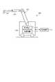
- FIG. 1is a diagram showing a schematic configuration of an endoscope system according to the first embodiment.
- FIG. 2is a block diagram showing a functional configuration of a main part of the endoscope system according to the first embodiment.
- FIG. 3is a diagram schematically showing the wavelength characteristics of the light emitted by each of the second light source unit and the third light source unit according to the first embodiment.
- FIG. 4is a diagram schematically showing the configuration of the pixel portion according to the first embodiment.
- FIG. 5is a diagram schematically showing the configuration of the color filter according to the first embodiment.
- FIG. 6is a diagram schematically showing the sensitivity and wavelength band of each filter.
- FIG. 7Ais a diagram schematically showing a signal value of the R pixel of the image pickup device according to the first embodiment.
- FIG. 7Bis a diagram schematically showing the signal value of the G pixel of the image pickup device according to the first embodiment.
- FIG. 7Cis a diagram schematically showing the signal value of the B pixel of the image pickup device according to the first embodiment.
- FIG. 8is a diagram schematically showing the configuration of the cut filter according to the first embodiment.
- FIG. 9is a diagram schematically showing the transmission characteristics of the cut filter according to the first embodiment.
- FIG. 10is a diagram schematically showing an observation principle in the narrow band light observation mode according to the first embodiment.
- FIG. 11is a diagram schematically showing an observation principle in the heat treatment observation mode according to the first embodiment.
- FIG. 12is a diagram schematically showing an observation principle in the normal light observation mode according to the first embodiment.
- FIG. 13is a flowchart showing a conventional procedure for urinary bladder tumor resection by PDD.
- FIG. 14is a diagram showing an example of a fluorescence image displayed during urinary tract bladder tumor resection by conventional PDD.
- FIG. 15is a flowchart of a procedure for urinary bladder tumor resection using the endoscopic system according to the first embodiment.
- FIG. 16is a diagram showing an example of a white light image displayed during urinary bladder tumor resection using the endoscopic system according to the first embodiment.
- FIG. 17is a diagram showing an example of a fluorescence image displayed during urinary tract bladder tumor resection using the endoscopic system according to the first embodiment.
- FIG. 18is a flowchart showing an outline of the process executed by the endoscope system 1 according to the first embodiment.
- FIG. 19is a diagram showing an example of a pseudo color image.
- FIG. 20is a diagram showing an example of a fluorescence image.
- FIG. 21is a diagram schematically showing a determination method for determination by the determination unit according to the first embodiment.
- FIG. 22is a block diagram showing a functional configuration of a main part of the endoscope system according to the second embodiment.
- FIG. 23is a flowchart showing an outline of the processing executed by the endoscope system according to the second embodiment.
- FIG. 24is a block diagram showing a functional configuration of a main part of the endoscope system according to the third embodiment.
- FIG. 25is a flowchart showing an outline of the processing executed by the endoscope system according to the third embodiment.
- FIG. 26is a diagram showing a schematic configuration of the endoscope system according to the fourth embodiment.
- FIG. 27is a block diagram showing a functional configuration of a main part of the endoscope system according to the fourth embodiment.
- FIG. 28is a diagram showing a schematic configuration of the surgical microscope system according to the fifth embodiment.
- FIG. 29is a block diagram showing a functional configuration of a main part of the endoscope system according to the sixth embodiment.
- FIG. 30is a diagram schematically showing the transmission characteristics of the cut filter according to the sixth embodiment.
- FIG. 31is a diagram schematically showing an observation principle in the heat treatment observation mode according to the sixth embodiment.
- FIG. 32is a diagram schematically showing the observation principle in the normal light observation mode according to the sixth embodiment.
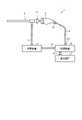
- FIG. 1is a diagram showing a schematic configuration of an endoscope system according to the first embodiment.
- the endoscope system 1 shown in FIG. 1is used in the medical field and is a system for observing a living tissue in a subject such as a living body.
- a rigid endoscope system using the rigid mirror (insertion portion 2) shown in FIG. 1will be described as the endoscope system 1, but the endoscope system 1 is not limited to this, and for example, it is flexible. It may be an endoscope system including an endoscope.
- the endoscope system 1is provided with a medical imaging device for imaging a subject, and performs surgery, treatment, etc.
- the endoscope system 1 shown in FIG. 1is used when performing surgery or treatment on a subject using a treatment tool (not shown) such as an energy device capable of heat treatment. Specifically, the endoscopic system 1 shown in FIG. 1 is used for transurethral resection of bladder tumor (TUR-Bt), and when treating a tumor (bladder cancer) or a lesion area of the bladder. Used for.
- a treatment toolsuch as an energy device capable of heat treatment.
- the endoscope system 1 shown in FIG. 1includes an insertion unit 2, a light source device 3, a light guide 4, an endoscope camera head 5 (endoscope image pickup device), a first transmission cable 6, and a first transmission cable 6.
- a display device 7, a second transmission cable 8, a control device 9, and a third transmission cable 10are provided.
- the insertion portion 2is hard or at least partially soft and has an elongated shape.
- the insertion portion 2is inserted into a subject such as a patient via a trocar.
- the insertion portion 2is provided with an optical system such as a lens for forming an observation image inside.
- the light source device 3is connected to one end of the light guide 4, and under the control of the control device 9, supplies the illumination light to irradiate the inside of the subject to one end of the light guide 4.
- the light source device 3includes one or more light sources such as an LED (Light Emitting Diode) light source, a xenon lamp, and a semiconductor laser element such as an LD (laser Diode), and an FPGA (Field Programmable Gate Array) or CPU (Central Processing Unit). It is realized by using a processor which is a processing device having hardware such as) and a memory which is a temporary storage area used by the processor.
- the light source device 3 and the control device 9may be configured to communicate individually as shown in FIG. 1, or may be configured to be integrated.
- One end of the light guide 4is detachably connected to the light source device 3, and the other end is detachably connected to the insertion portion 2.
- the light guide 4guides the illumination light supplied from the light source device 3 from one end to the other and supplies the illumination light to the insertion unit 2.
- the eyepiece 21 of the insertion portion 2is detachably connected to the endoscope camera head 5.
- the endoscope camera head 5receives an observation image imaged by the insertion unit 2 and performs photoelectric conversion to generate an imaging signal (RAW data), and this imaging signal is generated. Is output to the control device 9 via the first transmission cable 6.
- the first transmission cable 6transmits an image pickup signal output from the endoscope camera head 5 to the control device 9, and transfers setting data, power, and the like output from the control device 9 to the endoscope camera head 5.
- the setting datais a control signal, a synchronization signal, a clock signal, or the like that controls the endoscope camera head 5.
- the display device 7displays an observation image based on the image pickup signal processed by the control device 9 and various information related to the endoscope system 1.
- the display device 7is realized by using a display monitor such as a liquid crystal display or an organic EL (Electro Luminescence).
- the second transmission cable 8transmits the image pickup signal processed by the control device 9 to the display device 7.
- the control device 9is realized by using a processor which is a processing device having hardware such as a GPU (Graphics Processing Unit), an FPGA or a CPU, and a memory which is a temporary storage area used by the processor.
- the control device 9passes through each of the first transmission cable 6, the second transmission cable 8 and the third transmission cable 10 according to the program recorded in the memory, and the light source device 3 and the endoscope camera head 5 And the operation of the display device 7 is collectively controlled. Further, the control device 9 performs various image processing on the image pickup signal input via the first transmission cable 6 and outputs the image processing to the second transmission cable 8.
- One end of the third transmission cable 10is detachably connected to the light source device 3, and the other end is detachably connected to the control device 9.
- the third transmission cable 10transmits the control data from the control device 9 to the light source device 3.
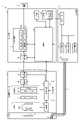
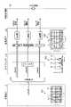
- FIG. 2is a block diagram showing a functional configuration of a main part of the endoscope system 1.
- the insertion portion 2has an optical system 22 and an illumination optical system 23.
- the optical system 22forms a subject image by condensing light such as reflected light reflected from the subject, return light from the subject, excitation light from the subject, and light emitted by the subject.
- the optical system 22is realized by using one or more lenses or the like.
- the illumination optical system 23is supplied from the light guide 4 and irradiates the subject with the illumination light.
- the illumination optical system 23is realized by using one or more lenses or the like.
- the light source device 3includes a condenser lens 30, a first light source unit 31, a second light source unit 32, a third light source unit 33, and a light source control unit 34.
- the condenser lens 30collects the light emitted by each of the first light source unit 31, the second light source unit 32, and the third light source unit 33, and emits the light to the light guide 4.
- the first light source unit 31emits white light (normal light), which is visible light, to supply white light to the light guide 4 as illumination light.
- the first light source unit 31is configured by using a collimating lens, a white LED lamp, a drive driver, and the like.
- the first light source unit 31may supply visible white light by simultaneously emitting light using a red LED lamp, a green LED lamp, and a blue LED lamp.
- the first light source unit 31may be configured by using a halogen lamp, a xenon lamp, or the like.
- the second light source unit 32emits the first narrow band light having a predetermined wavelength band to supply the first narrow band light to the light guide 4 as illumination light.
- the first narrow band lighthas a wavelength band of 530 nm to 550 nm (center wavelength is 540 nm).
- the second light source unit 32is configured by using a green LED lamp, a collimating lens, a transmission filter that transmits light of 530 nm to 550 nm, a drive driver, and the like.
- the third light source unit 33emits a second narrow-band light having a wavelength band different from that of the first narrow-band light, thereby causing the light guide 4 to emit the second narrow-band light.
- the second narrow band lighthas a wavelength band of 400 nm to 430 nm (center wavelength is 415 nm).
- the third light source unit 33is realized by using a collimating lens, a semiconductor laser such as a purple LD (laser Diode), a drive driver, or the like.
- the second narrow band lightfunctions as an excitation light for exciting the advanced glycation end product produced by subjecting the living tissue to heat treatment.
- the light source control unit 34is realized by using a processor which is a processing device having hardware such as FPGA or CPU and a memory which is a temporary storage area used by the processor.
- the light source control unit 34controls the light emission timing and light emission time of each of the first light source unit 31, the second light source unit 32, and the third light source unit 33 based on the control data input from the control device 9. do.
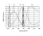
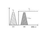
- FIG. 3is a diagram schematically showing the wavelength characteristics of the light emitted by each of the second light source unit 32 and the third light source unit 33.
- the horizontal axisindicates the wavelength (nm), and the vertical axis indicates the wavelength characteristic.
- the broken line L NGindicates the wavelength characteristic of the first narrow band light emitted by the second light source unit 32
- the broken line LVis the second narrow band light emitted by the third light source unit 33.
- the wavelength characteristic of (excitation light)is shown.
- the curve LBindicates a blue wavelength band
- the curve LGindicates a green wavelength band
- the curve LRindicates a red wavelength band.
- the second light source unit 32emits narrow band light having a center wavelength (peak wavelength) of 540 nm and a wavelength band of 530 nm to 550 nm. Further, the third light source unit 33 emits excitation light having a center wavelength (peak wavelength) of 415 nm and a wavelength band of 400 nm to 430 nm.
- each of the second light source unit 32 and the third light source unit 33emits the first narrow band light and the second narrow band light (excitation light) having different wavelength bands from each other.
- the endoscope camera head 5includes an optical system 51, a drive unit 52, an image sensor 53, a cut filter 54, an A / D conversion unit 55, a P / S conversion unit 56, an image pickup recording unit 57, and the like.
- An image pickup control unit 58is provided.
- the optical system 51forms an image of the subject image focused by the optical system 22 of the insertion unit 2 on the light receiving surface of the image pickup element 53.
- the optical system 51can change the focal length and the focal position.
- the optical system 51is configured by using a plurality of lenses 511.
- the optical system 51changes the focal length and the focal position by moving each of the plurality of lenses 511 on the optical axis L1 by the drive unit 52.
- the drive unit 52moves a plurality of lenses 511 of the optical system 51 along the optical axis L1 under the control of the image pickup control unit 58.
- the drive unit 52is configured by using a motor such as a stepping motor, a DC motor, and a voice coil motor, and a transmission mechanism such as a gear that transmits the rotation of the motor to the optical system 51.
- the image sensor 53is realized by using a CCD (Charge Coupled Device) or CMOS (Complementary Metal Oxide Semiconductor) image sensor having a plurality of pixels arranged in a two-dimensional matrix.
- the image pickup element 53is a subject image (light ray) imaged by the optical system 51 under the control of the image pickup control unit 58, receives a subject image passing through the cut filter 54, performs photoelectric conversion, and takes an image.
- a signal (RAW data)is generated and output to the A / D conversion unit 55.
- the image pickup device 53includes a pixel unit 531 and a color filter 532.
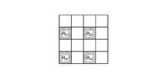
- FIG. 4is a diagram schematically showing the configuration of the pixel unit 531.
- the pixel unit 531reads an image signal as image data from the pixel P nm in the read area arbitrarily set as a read target among the plurality of pixels P nm , and is an A / D conversion unit. Output to 55.
- FIG. 5is a diagram schematically showing the configuration of the color filter 532.
- the color filter 532is composed of a Bayer array having 2 ⁇ 2 as one unit.
- the color filter 532is configured by using a filter R that transmits light in the red wavelength band, two filters G that transmit light in the green wavelength band, and a filter B that transmits light in the blue wavelength band. Will be done.
- FIG. 6is a diagram schematically showing the sensitivity and wavelength band of each filter.
- the horizontal axisindicates the wavelength (nm), and the vertical axis indicates the transmission characteristic (sensitivity characteristic).
- the curve LBshows the transmission characteristic of the filter B
- the curve LGshows the transmission characteristic of the filter G
- the curve L Rshows the transmission characteristic of the filter R.
- the filter Btransmits light in the blue wavelength band.
- the filter Gtransmits light in the green wavelength band.
- the filter Rtransmits light in the red wavelength band.
- the pixel P nm in which the filter R is arranged on the light receiving surfaceis an R pixel
- the pixel P nm in which the filter G is arranged on the light receiving surfaceis a G pixel
- the filter Bis arranged on the light receiving surface. Pixel P nm will be described as B pixel.
- the image pickup device 53configured in this way, when the subject image formed by the optical system 51 is received, as shown in FIGS. 7A to 7C, the colors of the R pixel, the G pixel, and the B pixel are respectively. Generates signals (R signal, G signal and B signal).
- the cut filter 54is arranged on the optical axis L1 of the optical system 51 and the image pickup device 53.
- the cut filter 54is provided on the light receiving surface side (incident surface side) of the G pixel provided with the filter G that transmits at least the green wavelength band of the color filter 532.
- the cut filter 54blocks light in a short wavelength wavelength band including the wavelength band of the excitation light, and transmits the wavelength band on the longer wavelength side than the wavelength band of the excitation light including the narrow band light.
- FIG. 8is a diagram schematically showing the configuration of the cut filter 54.
- the filter F 11 constituting the cut filter 54is located at the position where the filter G 11 (see FIG. 5) is arranged, and is arranged on the light receiving surface side directly above the filter G 11 . ..
- FIG. 9is a diagram schematically showing the transmission characteristics of the cut filter 54.
- the horizontal axisindicates the wavelength (nm), and the vertical axis indicates the transmission characteristic.
- the polygonal line LFshows the transmission characteristic of the cut filter 54
- the polygonal line L NGshows the first wavelength characteristic
- the polygonal line LVshows the wavelength characteristic of the excitation light.
- the cut filter 54shields the wavelength band of the excitation light and transmits the wavelength band on the long wavelength side from the wavelength band of the excitation light. Specifically, the cut filter 54 shields light in the wavelength band on the short wavelength side of 400 nm to less than 430 nm including the wavelength band of the excitation light, and has a wavelength band on the longer wavelength side than 400 nm to 430 nm including the excitation light. Transmits the light of.
- the A / D conversion unit 55performs A / D conversion processing on the analog image pickup signal input from the image pickup element 53 and outputs the analog image pickup signal to the P / S conversion unit 56.
- the A / D conversion unit 55is realized by using an A / D conversion circuit or the like.
- the P / S conversion unit 56Under the control of the image pickup control unit 58, the P / S conversion unit 56 performs parallel / serial conversion on the digital image pickup signal input from the A / D conversion unit 55, and the parallel / serial conversion is performed on the image pickup signal. Is output to the control device 9 via the first transmission cable 6.
- the P / S conversion unit 56is realized by using a P / S conversion circuit or the like.
- an E / O conversion unitthat converts the image pickup signal into an optical signal is provided, and the image pickup signal is output to the control device 9 by the optical signal.
- the image pickup signalmay be transmitted to the control device 9 by wireless communication such as Wi-Fi (Wireless Fidelity) (registered trademark).
- the image pickup recording unit 57records various information regarding the endoscope camera head 5 (for example, pixel information of the image pickup element 53, characteristics of the cut filter 54). Further, the image pickup recording unit 57 records various setting data and control parameters transmitted from the control device 9 via the first transmission cable 6.
- the image pickup recording unit 57is configured by using a non-volatile memory or a volatile memory.
- the image pickup control unit 58is a drive unit 52, an image pickup element 53, an A / D conversion unit 55, and a P / S conversion unit 56 based on the setting data received from the control device 9 via the first transmission cable 6. Control each operation.
- the image pickup control unit 58is realized by using a TG (Timing Generator), a processor which is a processing device having hardware such as a CPU, and a memory which is a temporary storage area used by the processor.
- the control device 9includes an S / P conversion unit 91, an image processing unit 92, an input unit 93, a recording unit 94, and a control unit 95.
- the S / P conversion unit 91performs serial / parallel conversion on the image data received from the endoscope camera head 5 via the first transmission cable 6 to perform image processing. Output to unit 92.
- an O / E conversion unitthat converts the optical signal into an electric signal may be provided instead of the S / P conversion unit 91.
- a communication module capable of receiving the wireless signalmay be provided instead of the S / P conversion unit 91.
- the image processing unit 92Under the control of the control unit 95, the image processing unit 92 performs predetermined image processing on the image pickup signal of the parallel data input from the S / P conversion unit 91 and outputs it to the display device 7.
- the predetermined image processingis demosaic processing, white balance processing, gain adjustment processing, gamma correction processing, format conversion processing, and the like.
- the image processing unit 92is realized by using a processor which is a processing device having hardware such as GPU or FPGA and a memory which is a temporary storage area used by the processor.
- the image processing unit 92functions as a support device.
- the image processing unit 92includes a generation unit 921, a specific unit 922, a determination unit 923, and an output unit 924.
- the generation unit 921generates a first image containing one or more feature areas that need to be excised by the operator and a second image containing one or more cauterized areas cauterized by an energy device. Specifically, the generation unit 921 is based on an imaging signal generated by imaging the reflected light and the return light from the living tissue when the living tissue is irradiated with narrow-band light having a narrower wavelength band than the white light. To generate the first image. More specifically, the generation unit 921 reflects when the living tissue is irradiated with the first narrow band light and the second narrow band light in the narrow band light observation mode of the endoscope system 1 described later.
- a first imageis generated, which is a pseudo-color image including one or more characteristic regions (lesion regions) that need to be excised by the operator. Further, the generation unit 921 captures an image of fluorescence generated by the excitation light irradiated to excite the advanced glycation end product produced by subjecting the living tissue to thermal treatment in the heat treatment observation mode of the endoscope system 1 described later. A second image is generated based on the image pickup signal generated thereby.
- the specific unit 922calculates the hue H of each pixel with respect to the first image which is a pseudo color image generated by the generation unit 921, and features a pixel having a brown color (for example, a hue H of 5 to 35) as a characteristic region (for example, a pixel having a hue H of 5 to 35). Identify as lesion area).
- the hue His one of the color attributes (hue, saturation and lightness), and is a color aspect expressed by a numerical value in the range of 0 to 360 using the so-called Hue circle of Mansell (for example,). , Red, blue and yellow).
- the specific unit 922determines whether or not each pixel of the first image, which is a pseudo-color image generated by the generation unit 921, has a predetermined luminance (gradation value) or more, and determines whether or not the predetermined luminance is equal to or higher than the predetermined luminance (gradation value).
- the characteristic region (lesion region)may be specified by extracting the above pixels.
- the specific unit 922determines whether or not each pixel of the second image, which is a fluorescent image generated by the generation unit 921, is equal to or higher than a predetermined threshold value for each pixel brightness value (gradation value). Then, a pixel having a predetermined threshold value or more is specified as an ablation region.
- the determination unit 923determines whether or not the feature region is included in the cauterization region based on the first image and the second image generated by the generation unit 921. Specifically, the determination unit 923 determines whether or not all of the feature regions are included in the cauterization region based on the first image and the second image generated by the generation unit 921.
- the output unit 924When the determination unit 923 determines that the characteristic region (lesion region) is not included in the cauterized region, the output unit 924 outputs information indicating that the characteristic region (lesion region) that has not yet been cauterized exists. ..
- the input unit 93receives inputs for various operations related to the endoscope system 1 and outputs the accepted operations to the control unit 95.
- the input unit 93is configured by using a mouse, a foot switch, a keyboard, a button, a switch, a touch panel, and the like.
- the recording unit 94is realized by using a recording medium such as a volatile memory, a non-volatile memory, an SSD (Solid State Drive), an HDD (Hard Disk Drive), or a memory card.
- the recording unit 94records data including various parameters necessary for the operation of the endoscope system 1. Further, the recording unit 94 has a program recording unit 941 for recording various programs for operating the endoscope system 1.
- the control unit 95is realized by using a processor which is a processing device having hardware such as FPGA or CPU and a memory which is a temporary storage area used by the processor.
- the control unit 95comprehensively controls each unit constituting the endoscope system 1.
- FIG. 10is a diagram schematically showing the observation principle in the narrow band light observation mode.
- Narrow band imagingis an observation method that emphasizes the capillaries and mucosal surface structure of the mucosal surface layer of living tissue by utilizing the fact that hemoglobin in blood strongly absorbs light near the wavelength of 415 nm. Is. That is, in the narrow-band light observation mode, two narrow-banded first narrow-band light (wavelength band is 530 nm to 550 nm) and second narrow-band light (wavelength band is 390 nm) that are easily absorbed by hemoglobin in blood. ⁇ 445 nm) is applied to a subject such as a living tissue. As a result, the narrow-band light observation mode can highlight the capillaries on the mucosal surface layer and the mucosal fine pattern, which are difficult to see with normal light (white light).
- the light source device 3causes the second light source unit 32 and the third light source unit 33 to emit light under the control of the control device 9.
- the first narrow band light W1 and the second narrow band light W2are applied to the living tissue O1 (mucosa) of the subject.
- at least the reflected light and the return light(hereinafter, simply referred to as “reflected light WR1, WR2, WG1, WG2, WB1, WB2”) containing a plurality of components reflected by the biological tissue O1 such as the subject are partially. Is shielded from light by the cut filter 54, and the rest is incident on the image sensor 53.
- the reflected light from the first narrow band light W1is the reflected light WR1, the reflected light WG1, and the reflected light WB1
- the reflected light from the second narrow band light W2is the reflected light WR2 and the reflected light WG2.
- the reflected light WB2will be described.
- the intensity of the component (light amount or signal value) of each lineis expressed by the thickness.
- the cut filter 54is the reflected light WG2 incident on the G pixel, and is short including the wavelength band of the second narrow band light W2.
- the reflected light WG2 in the wavelength band of the wavelengthis shielded from light.
- the cut filter 54transmits the reflected light WG1 in the wavelength band on the longer wavelength side than the wavelength band of the second narrowband light W2 including the first narrowband light W1. Further, reflected light (reflected light WR1, WR2, WB1, WB2) reflected by the subject by the first narrow band light W1 and the second narrow band light W2 is incident on each of the R pixel and the B pixel.
- each of the R pixel, the G pixel, and the B pixelhas different transmission characteristics (sensitivity characteristics). Specifically, since the B pixel does not have sensitivity to the reflected light WB1 of the first narrow band light W1, the output value corresponding to the received light amount of the reflected light WB1 is a minute value, while the second narrow band light W1. Since it has sensitivity to the reflected light WB2 of the band light W2, the output value corresponding to the received light amount of the reflected light WB1 becomes a large value.
- the image processing unit 92acquires an image pickup signal (RAW data) from the image pickup element 53 of the endoscope camera head 5, and images for each signal value of the G pixel and the B pixel included in the acquired image pickup signal. Processing is performed to generate a pseudo color image (narrow band image).
- the signal value of the G pixelincludes deep mucosal layer information of the subject.
- the signal value of the B pixelincludes the mucosal surface layer information of the subject. Therefore, the image processing unit 92 performs image processing such as gain control processing, pixel complementation processing, and mucosal enhancement processing on each signal value of the G pixel and the B pixel included in the image pickup signal to obtain a pseudo color image.
- the pseudo color imageis an image generated by using only the signal value of the G pixel and the signal value of the B pixel. Further, the image processing unit 92 acquires the signal value of the R pixel, but deletes it without using it for generating a pseudo color image.
- the narrow-band light observation modecan highlight the capillaries and fine patterns of the mucous membrane on the surface of the mucous membrane, which are difficult to see with white light (normal light).
- FIG. 11is a diagram schematically showing the observation principle in the heat treatment observation mode.
- ESDEndoscopic Submucosal Dissection
- LCSLaparoscopy and Endoscopy
- NEWSnon-exposed endoscopic wall-inversion Surgery
- TUR-bttransurethral resection of the blader tumor
- a surgeonwhen performing treatment, for example, as a pretreatment, a surgeon such as a doctor emits energy such as high frequency, ultrasonic waves, microwaves, etc. for marking the surgical target area.
- the characteristic area (pathogenic area) having a lesion on the living tissueis excised by cautery or marked by heat treatment.
- the surgeonalso performs treatments such as excision and coagulation of the biological tissue of the subject using an energy device or the like even in the case of actual treatment.
- the actual situationis that the surgeon relies on visual inspection, tactile sensation, intuition, etc. to confirm the degree of heat treatment applied to the living tissue by the energy device. For this reason, in the treatment using conventional energy devices and the like, it is difficult for the operator to confirm in real time the degree to which heat treatment should be applied during work such as surgery, and it is a work item that requires a great deal of skill. .. As a result, the surgeon and others have desired a technique capable of visualizing the cauterized state in the heat-treated area by heat treatment when the living tissue is heat-treated using an energy device.
- AGEsadvanced glycation end products
- AGEswhen AGEs are heat-treated with an energy device, amino acids and reducing sugars in the living tissue are heated to cause a Maillard reaction.
- the AGEs produced by this heatingcan be visualized by observing the state of heat treatment by fluorescence observation.
- AGEsare known to emit stronger fluorescence than the autofluorescent substances originally present in living tissues.
- the heat treatment observation modeis an observation method for visualizing the heat treatment area by heat treatment by utilizing the fluorescence characteristics of AGEs generated in the living tissue by heat treatment with an energy device or the like. Therefore, in the thermal treatment observation mode, the living body tissue is irradiated with blue light having a wavelength of around 415 nmm for exciting AGEs from the light source device 3. Thereby, in the heat treatment observation mode, the heat treatment image (fluorescence image) obtained by capturing the fluorescence generated from the AGEs (for example, green light having a wavelength of 490 to 625 nm) can be observed.
- the light source device 3causes the third light source unit 33 to emit light under the control of the control device 9, whereby the excitation light (center wavelength 415 nm) is emitted.
- the second narrow-band light W2is irradiated to the biological tissue O2 (heat-treated region) in which the subject is heat-treated by an energy device or the like.
- the reflected lightincluding at least the component of the second narrow band light W2 reflected by the biological tissue O2 (heat treatment region) and the return light (hereinafter, simply "reflected light WR10").
- Reflected light WG10, Reflected light WB10is shielded by the cut filter 54, and a part of the component on the long wavelength side is incident on the image pickup element 53.
- the intensity of the component (light amount or signal value) of each lineis expressed by the thickness.
- the cut filter 54is the reflected light WG2 incident on the G pixel, and has a short wavelength band including the wavelength band of the second narrow band light W2.
- the reflected light WG2 ofis shielded from light.
- the cut filter 54transmits the fluorescent WF1 in which the AGEs in the living tissue O1 (heat treatment region) self-emit. Therefore, the reflected light (reflected light WR12, reflected light WB12) and the fluorescent WF1 are incident on each of the R pixel and the B pixel. Further, the fluorescent WF1 is incident on the G pixel.
- the cut filter 54is arranged on the light receiving surface side (incident surface side), the fluorescent component is buried in the reflected light WG2 of the second narrow band light W2 which is the excitation light. Can be prevented.
- the G pixelhas sensitivity to fluorescence, but the output value is small because the fluorescence is a minute reaction.
- the image processing unit 92acquires image data (RAW data) from the image pickup element 53 of the endoscope camera head 5, and images for each signal value of the G pixel and the B pixel included in the acquired image data. Processing is performed to generate a fluorescent image (pseudo-color image).
- the signal value of the G pixelincludes the fluorescence information emitted from the heat treatment region.
- the B pixelcontains background information which is a living tissue around the heat treatment region. Therefore, the image processing unit 92 performs image processing such as gain control processing, pixel complementation processing, and mucosal enhancement processing on each signal value of G pixel and B pixel included in the image data to obtain a fluorescent image (pseudo).
- the image processing unit 92makes the gain for the signal value of the G pixel larger than the gain for the signal value of the G pixel during normal light observation, while the gain for the signal value of the B pixel is the gain for the signal value of the B pixel of the B pixel during normal light observation.
- Gain control processingis performed to make the gain smaller than the gain for the signal value.
- the image processing unit 92performs gain control processing so that the signal value of the G pixel and the signal value of the B pixel are the same (1: 1).
- the biological tissue O2heat treatment region of the heat treatment by the energy device or the like can be easily observed.
- FIG. 12is a diagram schematically showing the observation principle in the normal light observation mode.
- the light source device 3irradiates the living tissue O3 of the subject with white light W3 by causing the first light source unit 31 to emit light under the control of the control device 9.
- a part of the reflected light and the return light reflected by the living tissue(hereinafter, simply referred to as "reflected light WR40, reflected light WG40, reflected light WB40") is shielded by the cut filter 54, and the rest is shielded by the image pickup element 53.
- the cut filter 54is reflected light (reflected light WG30) incident on the G pixel, and has a short wavelength band including the wavelength band of the second narrow band light W2. It blocks the reflected light of. Therefore, as shown in FIG. 12, the light component in the blue wavelength band incident on the G pixel is smaller than that in the state where the cut filter 54 is not arranged.
- the image processing unit 92acquires image data (RAW data) from the image pickup element 53 of the endoscope camera head 5, and the signal values of the R pixel, the G pixel, and the B pixel included in the acquired image data. Image processing is performed on the image to generate a white light image. In this case, the image processing unit 92 adjusts the white balance so that the ratios of the red component, the green component, and the blue component are constant because the blue component contained in the image data is smaller than that of the conventional white light observation. Perform white balance adjustment processing.
- a natural white light image(observation image) can be observed even when the cut filter 54 is arranged on the light receiving surface side of the G pixel.
- FIG. 13is a flowchart showing a conventional procedure for urinary bladder tumor resection by PDD.
- the surgeonfirst identifies a bladder tumor with respect to a subject such as a patient (step S1). Specifically, the surgeon confirms whether or not a tumor of the subject is generated by a tumor marker or the like by urinalysis, and performs an endoscopic (cystoscopic) examination. In this case, the surgeon uses an endoscope to collect the urinary cells of the subject with a raw needle. In addition, the surgeon identifies the bladder tumor of the subject by performing various examinations such as abdominal ultrasonography, CT examination, and MRI examination on the subject.
- the surgeonmakes a definitive diagnosis of the urinary cells collected by the case with a microscope, and based on various tests, the subject's T (depth of bladder cancer), N ( The presence or absence of lymph node metastasis) and M (presence or absence of distant metastasis of lung, liver, bone, etc.) are judged, and the stage of bladder tumor in the subject is specified.
- the surgeonidentifies the bladder tumor and then administers 5-ALA to the subject (step S2). Specifically, the surgeon causes the subject to take a drug containing 5-ALA before the operation of the subject.
- the surgeoninserts an endoscope through the urethra of the subject (step S3) and confirms a specific region (lesion region) including the tumor position in the bladder by the white light of the endoscope (step S4).
- the operatorroughly confirms the specific area including the tumor position while confirming with the observation image displayed on the display device.
- the surgeonexcises the lesion region including the lesion portion of the subject via an endoscope by cauterizing it with an energy device or the like while checking the fluorescence image P1 displayed on the display device (step). S5).
- the surgeonswitches the endoscope to PDD and irradiates the endoscope with a second narrow band light to perform observation by PDD (step S6).
- the surgeonconfirms the fluorescence image P1 by PDD displayed on the display device, and the fluorescent region W1 that emits red light is a specific region (lesion) including a lesion such as a tumor. Confirm as area).
- the surgeondetermines whether or not the tumor has been resected by observing the fluorescent image P1 displayed on the display device (step S5), and when all the tumors have been resected (step). S6: Yes), the surgeon finishes this procedure. Specifically, the operator can determine whether or not all of the fluorescence region W1 of the fluorescence image P1 can be excised while observing the fluorescence image P1 displayed on the display device, and can excise all of the fluorescence region W1. If this is the case, it is determined that the excision of the specific area (lesion area) including the lesion part such as a tumor has been completed, and this procedure is terminated.
- step S6when the excision of all the tumors is not completed (step S6: No), the operator returns to the above-mentioned step S4 and alternates between the observation image by white light and the fluorescence image P1 by PDD. While switching the observation mode of the endoscope, this procedure is performed until the fluorescence region W1 is cauterized by an energy device or the like.
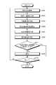
- FIG. 15is a flowchart of a procedure for urinary bladder tumor resection using the endoscopic system 1 of the present disclosure.
- the surgeonfirst identifies a bladder tumor with respect to a subject such as a patient (step S10). Specifically, the surgeon identifies the bladder tumor of the subject by the same method as the above-mentioned PDD-based urinary bladder tumor resection.
- the surgeoninserts the insertion portion 2 (rigid mirror) into the urethra of the subject (step S11), irradiates the light source device 3 with white light into the subject, and displays the observation image displayed by the display device 7. While observing, the characteristic region (lesion region) including the tumor position is confirmed (step S11). Specifically, as shown in FIG. 16, the characteristic region (lesion region) including the tumor position is confirmed while observing with the white light image P2 displayed on the display device 7.
- the operatorconfirms the white light image P2 displayed on the display device 7 and uses an energy device or the like to create a characteristic region (lesion region) including a lesion portion such as a tumor of the subject via the insertion portion 2. It is excised by cauterizing (step S13). Specifically, as shown in FIG. 16, the operator excises the characteristic region (lesion region) by cauterizing it with an energy device or the like while confirming it with the white light image P2 displayed on the display device 7.
- the operatorirradiates the light source device 3 with a second narrow band light (excitation light) which is the excitation light, and observes the fluorescence image displayed by the display device 7 (step S14).
- a second narrow band lightexcitation light
- the surgeondetermines whether or not the excision of the characteristic region (lesion region) including the tumor position is completed by observing the fluorescent image displayed by the display device 7 (step S15), and determines the tumor position.
- the excision of the including characteristic area (lesion area)is completed (step S15: Yes)
- the operatorends the procedure. Specifically, as shown in FIG. 17, the operator observes the fluorescent image P3 displayed by the display device 7 and observes the cauterized region R10 excised by cauterizing with an energy device or the like, thereby observing the tumor position.
- step S15the process returns to step S12, the light source device 3 is irradiated with white light, and the display device 7 displays.
- the white light image P2 to be displayed and the fluorescence image P3 displayed by the display device 7 by irradiating the subject with a second narrow band light (excitation light) which is an excitation light to the light source device 3are alternately performed.
- the display device 7displays information indicating the existence of a lesion region (characteristic region) including a tumor position that has not yet been cauterized.
- the tumor of the subjectcan be resected without administering 5-ALA to the subject. Since the characteristic region (lesion region) including the tumor position and the cautery region can be easily grasped, it is possible to prevent the tumor from being left behind.
- FIG. 18is a flowchart showing an outline of the process executed by the endoscope system 1.
- control unit 95controls the light source control unit 34 to cause the first light source unit 31 to emit light and irradiate the subject with white light (step S101).
- the generation unit 921generates a white light image by acquiring an image pickup signal from the image pickup element 53 of the endoscope camera head 5 (step S102).
- the output unit 924causes the display device 7 to display the white light image generated by the generation unit 921.
- control unit 95controls the light source control unit 34 to cause the second light source unit 32 and the third light source unit 33 to emit light and irradiate the subject with the first and second narrow band lights. (Step S103).
- the generation unit 921generates a first image which is a pseudo color image by acquiring an image pickup signal from the image pickup element 53 of the endoscope camera head 5 (step S104).
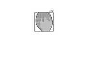
- the specific unit 922identifies the characteristic region (lesion region) from the first image generated by the generation unit 921 (step S105). Specifically, the specific unit 922 calculates the hue H of each pixel with respect to the first image which is a pseudo color image generated by the generation unit 921, and has a brown color (for example, the hue H is 5 to 35). The pixel is specified as a characteristic area (lesion area). For example, as shown in FIG. 19, the specific unit 922 calculates the hue H of each pixel with respect to the first image P10, and features a pixel having a brown color (for example, hue H is 5 to 35) as a characteristic region (lesion). Region), for example feature regions R1 and R2.
- control unit 95controls the light source control unit 34 to cause the third light source unit 33 to emit light and irradiate the subject with the second narrow band light which is the excitation light (step S106). ..
- the generation unit 921generates a second image by acquiring an image pickup signal from the image pickup element 53 of the endoscope camera head 5 (step S107).
- the specific unit 922specifies the cautery region from the second image (step S108). Specifically, the specific unit 922 determines whether or not the brightness is equal to or higher than the predetermined brightness for each pixel of the second image, and identifies the ablation region by extracting the pixels having the predetermined brightness or higher. do. Specifically, as shown in FIG. 20, the specific unit 922 determines whether or not each pixel of the second image P11 has a predetermined brightness or higher, and determines whether or not the pixel has a predetermined brightness or higher.
- the cautery regions R10 and R11are specified by extraction.
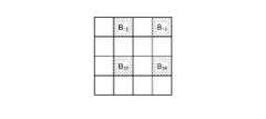
- the determination unit 923determines whether or not the characteristic region is included in the cautery region (step S109). Specifically, as shown in FIG. 21, the determination unit 923 includes the feature regions R1 and R2 extracted from the first image P10 by the specific unit 922 and the cauterization regions R10 and R11 extracted from the second image P11. , To determine whether or not the feature regions R1 and R2 are included in the ablation regions R10 and R11. For example, in the case shown in FIG. 21, the determination unit 923 determines that there is a feature region that has not been cauterized yet because a part of the feature region R1 is out of the cauterization regions R10 and R11, and the feature region is set to the cauterization region. Judge that it is not included.
- step S109: Yesthe endoscope system 1 shifts to step S111 described later.
- step S109: Nothe endoscope system 1 shifts to step S110 described later.
- step S110the output unit 924 notifies the display device 7 of information indicating the existence of a characteristic region (lesion region) that has not yet been cauterized.
- the surgeoncan grasp that there is a region requiring cauterization by an energy device or the like with respect to the characteristic region (lesion region) of the subject, so that the characteristic region (lesion region) can be easily left behind. Can be grasped.
- step S111: Yeswhen the end signal for terminating the observation of the subject is input via the input unit 93 (step S111: Yes), the endoscope system 1 ends this process. On the other hand, when the end signal for terminating the observation of the subject is not input via the input unit 93 (step S111: No), the endoscope system 1 returns to the above-mentioned step S101.
- the output unit 924when the determination unit 923 determines that the characteristic region is not included in the cauterized region, the output unit 924 has a characteristic region (lesion region) that has not yet been cauterized. Is notified by outputting the information indicating the above to the display device 7. Therefore, the operator can easily grasp the leftover of the characteristic region (lesion region).
- the generation unit 921is an image pickup signal from the image pickup element 53 of the endoscope camera head 5, and the wavelength band is narrower than that of white light with respect to the living tissue. Since the first image, which is a pseudo-color image, is generated by acquiring the image pickup signal generated by imaging the reflected light when irradiating the narrow band light and the return light from the living tissue, the excision by the operator is performed. A first image can be generated that includes one or more feature areas (lesion areas) that are required.
- the imaging signal generated by the generation unit 921imaging the fluorescence generated by the excitation light irradiated to excite the terminal saccharified product generated by subjecting the living tissue to heat treatment.
- the imaging signal generated by the generation unit 921imaging the fluorescence generated by the excitation light irradiated to excite the terminal saccharified product generated by subjecting the living tissue to heat treatment.
- the characteristic region(lesion region) is based on a pseudo-color image corresponding to the imaging signal generated by irradiating the first narrow band light and imaging the reflected light and the return light from the subject. ) was extracted, but in the second embodiment, the biological images of a plurality of subjects are associated with the information annotated with the characteristic region (lesion region) included in the plurality of biological images.
- the characteristic regionis specified from the white light image obtained by imaging the biological tissue using the trained model trained using the teacher data.
- the same components as those of the endoscope system 1 according to the first embodiment described aboveare designated by the same reference numerals, and detailed description thereof will be omitted.
- FIG. 22is a block diagram showing a functional configuration of a main part of the endoscope system according to the second embodiment.
- the endoscope system 1A shown in FIG. 22includes a light source device 3A and a control device 9A in place of the light source device 3 and the control device 9 of the endoscope system 1 according to the first embodiment described above.
- the light source device 3Aomits the second light source unit 32 capable of irradiating the first narrow band light from the light source device 3A according to the first embodiment described above.
- control device 9Afurther includes a lesion-learned model unit 96 in addition to the configuration of the control device 9 according to the first embodiment described above.
- the lesion-learned model unit 96records a lesion-learned model for identifying a characteristic region (lesion region) included in a white light image.
- the lesion-learned model unit 96is a teacher that associates biological images of a plurality of subjects with information annotated with characteristic regions (lesion regions) included in the plurality of biological images. Record the learning results learned using the data.
- the lesion-learned model unit 96inputs an image pickup signal generated by imaging the reflected light when the living tissue is irradiated with white light or the return light from the living tissue as input data, and the above-mentioned as output data. The position of the lesion area in the captured image corresponding to the captured signal is output.
- the lesion-learned modelconsists of a neural network in which each layer has one or more nodes.
- the type of machine learningis not particularly limited, but for example, a biological image of a plurality of subjects is associated with information annotated with a characteristic region (lesion region) included in the plurality of biological images. It suffices as long as the training data and the training data are prepared and the training data and the training data are input to the calculation model based on the multi-layer neural network to be trained.
- a machine learning methoda method based on DNN (Deep Neural Network), which is a multi-layer neural network such as CNN (Convolutional Neural Network) or 3D-CNN, is used.
- a method based on a recurrent neural network (RNN: Recurrent Neural Network), an LSTM (Long Short-Term Memory units) extended from the RNN, or the likemay be used.
- FIG. 23is a flowchart showing an outline of the process executed by the endoscope system 1A.
- steps S201 and S202correspond to steps S101 and S102 of FIG. 18 described above, respectively.
- the specific unit 922identifies a characteristic region (lesion region) from the white light image based on the trained model recorded by the lesion trained model unit 96 and the white light image generated by the generation unit 921. do. Specifically, the specific unit 922 inputs the white light image generated by the generation unit 921 into the lesion-learned model unit 96 as input data, and the position of the characteristic region output from the lesion-learned model unit 96 as output data. The characteristic region (lesion region) is identified from the white light image based on.
- Steps S204 to S209correspond to each of steps S106 to S111 in FIG. 18 described above. After step S209, the endoscope system 1A ends this process.
- the operatorcan easily grasp the leftover of the characteristic region (lesion region) as in the first embodiment described above.
- the surgeonoperates the input unit 93 while observing the white light image displayed on the display device 7 to annotate the characteristic region (tumor region) reflected in the white light image. Set the feature area.
- the same components as those of the endoscope system 1 according to the second embodiment described aboveare designated by the same reference numerals, and detailed description thereof will be omitted.
- FIG. 24is a block diagram showing a functional configuration of a main part of the endoscope system according to the third embodiment.
- the endoscope system 1B shown in FIG. 24includes a light source device 3A according to the above-mentioned second embodiment in place of the light source device 3 of the endoscope system 1 according to the above-mentioned first embodiment.
- FIG. 25is a flowchart showing an outline of the process executed by the endoscope system 1B.
- step S301 and step S302correspond to step S101 and step S102 of FIG. 18 described above, respectively.
- step S303when the operator inserts an annotation into the white light image via the input unit 93 (step S303: Yes), the endoscope system 1B shifts to step S304 described later.
- step S303: Nowhen the operator does not insert an annotation into the white light image via the input unit 93 (step S303: No), the endoscope system 1B shifts to step S311 described later.
- step S304the specific unit 922 specifies a region in the white light image designated according to the annotation insertion operation input from the input unit 93 as a specific region (lesion region).
- step S304the endoscope system 1 shifts to step S305 described later.
- Steps S305 to S310correspond to each of steps S106 to S111 in FIG. 18 described above. After step S310, the endoscope system 1B ends this process.
- the operatorcan easily grasp the leftover of the characteristic region (lesion region) as in the first embodiment described above.
- the fourth embodimentwill be described.
- the endoscope systemincludes a rigid mirror, but in the fourth embodiment, an endoscope system including a flexible endoscope will be described.
- the endoscope system according to the fourth embodimentwill be described.
- the same components as those of the endoscope system 1 according to the first embodiment described aboveare designated by the same reference numerals, and detailed description thereof will be omitted.
- FIG. 26is a diagram showing a schematic configuration of the endoscope system according to the fourth embodiment.
- FIG. 27is a block diagram showing a functional configuration of a main part of the endoscope system according to the fourth embodiment.
- the endoscope system 100 shown in FIGS. 26 and 27captures the inside of the subject by inserting it into the subject such as a patient, and the display device 7 displays a display image based on the captured image data.
- a surgeonsuch as a doctor inspects the presence or absence and the state of each of the bleeding site, the tumor site, and the abnormal region in which the abnormal site is shown.
- a surgeonsuch as a doctor inserts a treatment tool such as an energy device into the body of the subject via the treatment tool channel of the endoscope to treat the subject.
- the endoscope system 100includes an endoscope 102 in addition to the light source device 3, the display device 7, and the control device 9 described above.
- the configuration of the endoscope 102will be described.
- the endoscope 102generates image data by imaging the inside of the subject, and outputs the generated image data to the control device 9.
- the endoscope 102includes an operation unit 122 and a universal code 123.
- the insertion portion 121has an elongated shape with flexibility.
- the insertion portion 121is connected to a tip portion 124 having a built-in image pickup device, which will be described later, a bendable bending portion 125 composed of a plurality of bending pieces, and a base end side of the bending portion 125, and has a flexible length. It has a scale-shaped flexible tube portion 126 and.
- the tip portion 124is configured by using glass fiber or the like.
- the tip portion 124has a light guide 241 forming a light guide path for light supplied from the light source device 3, an illumination lens 242 provided at the tip of the light guide 241, and an image pickup device 243.
- the image pickup device 243includes an optical system 244 for condensing light, the image pickup element 53 of the first embodiment described above, a cut filter 54, an A / D conversion unit 55, a P / S conversion unit 56, an image pickup recording unit 57, and an image pickup.
- a control unit 58is provided.
- the image pickup device 243functions as a medical image pickup device.
- the universal code 123has at least a built-in light guide 241 and a condensing cable that bundles one or a plurality of cables.
- the collective cableis a signal line for transmitting and receiving signals between the endoscope 102, the light source device 3 and the control device 9, and is for transmitting and receiving a signal line for transmitting and receiving setting data and an image pickup image (image data).
- the universal cord 123has a connector portion 127 that can be attached to and detached from the light source device 3.
- the connector portion 127has a coil-shaped coil cable 127a extending therein, and has a connector portion 128 detachable from the control device 9 at the extending end of the coil cable 127a.
- the endoscope system 100configured in this way performs the same processing as the endoscope system 1 according to the first embodiment described above.
- the operatorcan easily grasp the leftover of the characteristic region (lesion region) as in the first embodiment described above.
- FIG. 28is a diagram showing a schematic configuration of the surgical microscope system according to the fifth embodiment.
- the surgical microscope system 300 shown in FIG. 28includes a microscope device 310, which is a medical imaging device acquired by capturing an image for observing a subject, and a display device 7. It is also possible to integrally configure the display device 7 and the microscope device 310.
- the microscope device 310is supported by a microscope unit 312 that magnifies and captures a minute part of a subject, a support unit 313 that is connected to the base end portion of the microscope unit 312, and includes an arm that rotatably supports the microscope unit 312. It has a base portion 314 that rotatably holds the base end portion of the portion 313 and can move on the floor surface.
- the base unit 314is a light source device 3 that generates white light, a first narrow band light, a second narrow band light, and the like that irradiate the subject from the microscope device 310, and a control device that controls the operation of the surgical microscope system 300. 9 and.
- Each of the light source device 3 and the control device 9has at least the same configuration as that of the first embodiment described above.
- the light source device 3includes a condenser lens 30, a first light source unit 31, a second light source unit 32, a third light source unit 33, and a light source control unit 34.
- the control device 9includes an S / P conversion unit 91, an image processing unit 92, an input unit 93, a recording unit 94, and a control unit 95.
- the base portion 314may not be movably provided on the floor surface, but may be fixed to a ceiling, a wall surface, or the like to support the support portion 313.
- the microscope unit 312has, for example, a columnar shape and has the above-mentioned medical imaging device inside the microscope unit 312.
- the medical imaging devicehas the same configuration as the endoscope camera head 5 according to the first embodiment described above.
- the microscope unit 312includes an optical system 51, a drive unit 52, an image sensor 53, a cut filter 54, an A / D conversion unit 55, a P / S conversion unit 56, an image pickup recording unit 57, and an image pickup.
- a control unit 58is provided.
- a switch for receiving an input of an operation instruction of the microscope device 310is provided on the side surface of the microscope unit 312.
- a cover glass that protects the insideis provided on the opening surface of the lower end of the microscope unit 312 (not shown).
- the shape of the microscope unit 312is preferably a shape that is elongated in the observation direction so that the user can easily grasp and change the viewing direction. Therefore, the shape of the microscope unit 312 may be a shape other than a columnar shape, and may be, for example, a polygonal columnar shape.
- the surgeoncan easily grasp the leftover of the characteristic region (lesion region) as in the first embodiment described above.
- the cut filter 54is provided on the light receiving surface side (incident surface side) of the G pixel, but in the sixth embodiment, the light receiving surface side of each of the R pixel, the G pixel, and the B pixel. It is provided on the (incident surface side).
- the endoscope system according to the sixth embodimentwill be described.
- the same components as those of the endoscope system 1 according to the first embodiment described aboveare designated by the same reference numerals, and detailed description thereof will be omitted.
- FIG. 29is a block diagram showing a functional configuration of a main part of the endoscope system according to the sixth embodiment.
- the endoscope system 400 shown in FIG. 29includes an endoscope camera head 5C instead of the endoscope camera head 5 according to the first embodiment described above. Further, the endoscope camera head 5C includes a cut filter 54C instead of the cut filter 54 according to the first embodiment described above.
- the cut filter 54Cis arranged on the optical path between the optical system 51 and the image pickup element 53.
- the cut filter 54Cblocks most of the light in the short wavelength wavelength band including the wavelength band of the excitation light (transmits a part of the excitation light), and the wavelength band on the longer wavelength side than the wavelength band that blocks most of this light. Is transparent.
- FIG. 30is a diagram schematically showing the transmission characteristics of the cut filter 54C.
- the horizontal axisindicates the wavelength (nm), and the vertical axis indicates the transmission characteristic.
- the polygonal line L FFshows the transmission characteristic of the cut filter 54C
- the polygonal line LVshows the wavelength characteristic of the excitation light
- the polygonal line L NGshows the wavelength characteristic in the fluorescence of AGEs.
- the cut filter 54Cshields most of the light in the wavelength band of the excitation light (transmits a part of the excitation light), and has a longer wavelength than the wavelength band that blocks most of the light. It transmits the wavelength band on the side.
- the cut filter 58shields most of the light in the wavelength band on the short wavelength side, which is less than any wavelength of 430 nm to 470 nm including the wavelength band of the excitation light, and shields most of the light. It transmits light in the wavelength band on the longer wavelength side than the wavelength band.
- the cut filter 54Ctransmits the fluorescence of AGEs generated by the thermal treatment as shown in the polygonal line L NG .
- FIG. 31is a diagram schematically showing the observation principle in the heat treatment observation mode.
- the light source device 3is the excitation light (center wavelength 415 nm) by causing the third light source unit 33 to emit light under the control of the control device 9.
- the narrow-band light W2is applied to the biological tissue O2 (heat-treated region) to which the subject has been heat-treated by an energy device or the like.
- at least the component of the excitation light reflected by the biological tissue O2 (heat treatment region) and the reflected light including the return lighthereinafter, simply referred to as “reflected light W100”) are cut. While the light is shielded by the filter 54C and the intensity is reduced, a part of the component on the wavelength longer side than the wavelength band that shields most of the light is incident on the image pickup element 53 without reducing the intensity.
- the cut filter 54Cis the reflected light W100 incident on the G pixel, and is the reflected light W100 having a short wavelength band including the wavelength band of the excitation light. Most of it is shielded (transmits a part of the excitation light), and the wavelength band on the longer wavelength side than the wavelength band that shields most of this is transmitted. Further, as shown in the graph G121 of FIG. 31, the cut filter 54C transmits the fluorescent WF100 in which the AGEs in the living tissue O2 (heat treatment region) self-emit. Therefore, the reflected light W100 and the fluorescent WF10 having reduced intensities are incident on each of the R pixel, the G pixel, and the B pixel.
- the G pixelhas sensitivity to fluorescence, but the output value is small because the fluorescence is a minute reaction.
- the image processing unit 92acquires image data (RAW data) from the image pickup element 53 of the endoscope camera head 5C, and images for each signal value of the G pixel and the B pixel included in the acquired image data. Processing is performed to generate a fluorescent image (pseudo-color image).
- the signal value of the G pixelincludes the fluorescence information emitted from the heat treatment region.
- the B pixelcontains background information from the biological tissue of the subject including the heat-treated region. Therefore, the image processing unit 92 performs the same processing as that of the first embodiment described above to generate a fluorescent image.
- the image processing unit 93includes demosaic processing, processing for calculating the intensity ratio for each pixel, processing for determining between the fluorescent region and the background region, color component signals (pixel values) of pixels located in the fluorescent region, and Image processing of parameters different from each other is performed on each of the color component signals (pixel values) of the pixels located in the background region to generate a fluorescent image (pseudo-color image). Then, the image processing unit 93 outputs the heat treatment image to the display device 7.
- the fluorescence regionis a region in which fluorescence information is superior to background information.
- the background regionrefers to a region where the background information is superior to the fluorescence information.
- the intensity ratio between the reflected light component signal corresponding to the background information and the fluorescence component signal corresponding to the fluorescence information contained in the pixelis equal to or higher than a predetermined threshold value (for example, 0.5 or higher). In some cases, it is determined as a fluorescent region, while when the intensity ratio is less than a predetermined threshold value, it is determined as a background region.
- a predetermined threshold valuefor example, 0.5 or higher
- the biological tissue O1heat treatment region of the heat treatment by the energy device or the like can be easily observed.
- FIG. 32is a diagram schematically showing the observation principle in the normal light observation mode.
- the light source device 3irradiates the living tissue O3 of the subject with white light by causing the first light source unit 31 to emit light under the control of the control device 9. ..
- a part of the reflected light and the return light reflected by the living tissue(hereinafter, simply referred to as "reflected light WR300, reflected light WG300, reflected light WB300") is shielded by the cut filter 54C, and the rest is shielded by the image pickup element 53.
- the cut filter 54Cshields the reflected light in a short wavelength band including the wavelength band of the excitation light. Therefore, as shown in the graph G231 of FIG. 34, the light component in the blue wavelength band incident on the B pixel is smaller than that in the state where the cut filter 54C is not arranged.
- the image processing unit 93acquires image data (RAW data) from the image pickup element 53 of the endoscope camera head 5A, and the signal values of the R pixel, the G pixel, and the B pixel included in the acquired image data. Image processing is performed on the image to generate a white image. In this case, the image processing unit 93 adjusts the white balance so that the ratios of the red component, the green component, and the blue component are constant because the blue component contained in the image data is smaller than that of the conventional white light observation. Perform white balance adjustment processing.
- the endoscope system 400performs the same processing as that of the first embodiment described above, determines the background region and the fluorescence region in the thermal treatment observation mode, and image processing parameters different from each other in each of the background region and the fluorescence region. Is applied to generate a fluorescent image in which the fluorescent region is emphasized from the background region and display it on the display device 7. Further, in the endoscopic system 400, even when the cut filter 54C is arranged in the normal light observation mode and the narrow band light observation mode, the light component in the blue wavelength band incident on the B pixel and the G. Since the light component in the green wavelength band incident on the pixel is only smaller than that in the state where the cut filter 54C is not arranged, a white image and a pseudo color image can be generated.
- the same effect as that of the first embodiment described aboveis obtained, and since the cut filter 54C as an optical element is provided, the reflected light and the return light reflected by the living tissue are covered with the reflected light and the return light. It is possible to prevent the fluorescence from the heat treatment region from being buried.
- Various inventionsare formed by appropriately combining a plurality of components disclosed in the endoscopic system according to the first to fourth and sixth embodiments of the present disclosure or the surgical microscope system according to the fifth embodiment described above. can do. For example, some components may be removed from all components described in the endoscopic system or operating microscope system according to the embodiment of the present disclosure described above. Further, the components described in the endoscopic system or the operating microscope system according to the embodiment of the present disclosure described above may be appropriately combined.
- the above-mentioned "part”can be read as “means” or "circuit".
- the control unitcan be read as a control means or a control circuit.
Landscapes
- Health & Medical Sciences (AREA)
- Life Sciences & Earth Sciences (AREA)
- Surgery (AREA)
- Engineering & Computer Science (AREA)
- Radiology & Medical Imaging (AREA)
- General Health & Medical Sciences (AREA)
- Physics & Mathematics (AREA)
- Medical Informatics (AREA)
- Nuclear Medicine, Radiotherapy & Molecular Imaging (AREA)
- Heart & Thoracic Surgery (AREA)
- Veterinary Medicine (AREA)
- Biomedical Technology (AREA)
- Optics & Photonics (AREA)
- Biophysics (AREA)
- Molecular Biology (AREA)
- Animal Behavior & Ethology (AREA)
- Pathology (AREA)
- Public Health (AREA)
- Signal Processing (AREA)
- Quality & Reliability (AREA)
- Computer Vision & Pattern Recognition (AREA)
- General Physics & Mathematics (AREA)
- Theoretical Computer Science (AREA)
- Endoscopes (AREA)
Abstract
Description
Translated fromJapanese本開示は、被検体を撮像した撮像信号に対して画像処理を施して出力する支援装置、内視鏡システム、支援方法およびプログラムに関する。The present disclosure relates to a support device, an endoscope system, a support method, and a program that perform image processing on an image pickup signal obtained by imaging a subject and output the image.
従来、経尿道的膀胱腫瘍切除術(TUR-Bt)において、被検体の尿道から手術用内視鏡(レゼクトスコープ)を挿入し、術者が手術用内視鏡の接眼部で病巣部を観察しながら、エネルギーデバイス等の切除用処置具によって病巣部を含む生体組織の切除を行う技術が知られている(例えば特許文献1を参照)。Conventionally, in transurethral resection of a bladder tumor (TUR-Bt), a surgical endoscope (resectoscope) is inserted from the urethra of the subject, and the operator uses the eyepiece of the surgical endoscope to detect the lesion. There is known a technique for excising a living tissue including a lesion with an excision treatment tool such as an energy device (see, for example, Patent Document 1).
ところで、上述した特許文献1では、術者が接眼部を経由して被検体の病巣部を含む特徴領域(病巣領域)と、切除用処置具によって焼灼された焼灼領域と、を目視で観察しているため、特徴領域と焼灼領域とを判別し辛く、特徴領域の取り残しを把握することが難しかった。By the way, in the above-mentioned
本開示は、上記に鑑みてなされたものであって、特徴領域の取り残しを容易に把握することができる支援装置、内視鏡システム、支援方法およびプログラムを提供することを目的とする。The present disclosure has been made in view of the above, and an object of the present disclosure is to provide a support device, an endoscope system, a support method, and a program that can easily grasp the leftover of a characteristic area.
上述した課題を解決し、目的を達成するために、本開示に係る支援装置は、術者による切除が必要な1つ以上の特徴領域を含む第1の画像と、エネルギーデバイスにより焼灼された1つ以上の焼灼領域を含む第2の画像と、を生成する生成部と、前記第1の画像と、前記第2の画像と、に基づいて、前記特徴領域が前記焼灼領域に含まれているか否かを判定する判定部と、前記判定部によって前記特徴領域が前記焼灼領域に含まれていないと判定された場合、未だ焼灼されていない前記特徴領域が存在することを示す情報を出力する出力部と、を備える。In order to solve the above-mentioned problems and achieve the object, the support device according to the present disclosure is a first image containing one or more feature areas that need to be excised by an operator, and cauterized by an energy device1. Whether the characteristic region is included in the cautery region based on a generation unit that generates a second image including one or more cautery regions, the first image, and the second image. An output that outputs information indicating that the characteristic region that has not been cauterized exists, when the determination unit determines whether or not the characteristic region is included in the cauterized region. It has a department.
また、本開示に係る支援装置は、上記開示において、前記生成部は、生体組織に熱処置を施すことによって生じる終末糖化産物を励起させるために照射された励起光によって発生した蛍光を撮像することによって生成した撮像信号に基づいて、前記第2の画像を生成する。Further, in the above disclosure, in the support device according to the present disclosure, the generation unit captures the fluorescence generated by the excitation light irradiated to excite the advanced glycation end product produced by subjecting the living tissue to heat treatment. The second image is generated based on the image pickup signal generated by.
また、本開示に係る支援装置は、上記開示において、前記生成部は、生体組織に対して白色光より波長帯域が狭い狭帯域光を照射した際の反射光および前記生体組織からの戻り光を撮像することによって生成した撮像信号に基づいて、前記第1の画像を生成する。Further, in the above disclosure, in the support device according to the present disclosure, the generation unit emits reflected light and return light from the biological tissue when the biological tissue is irradiated with narrow band light having a narrower wavelength band than white light. The first image is generated based on the image pickup signal generated by the image pickup.
また、本開示に係る支援装置は、上記開示において、複数の生体画像と、該複数の生体画像の各々の特徴領域と、を対応付けた学習データを学習し、入力データとして生体組織に対して白色光を照射した際の反射光および前記生体組織からの戻り光を撮像することによって生成した撮像信号を入力し、出力データとして前記撮像信号に対応する撮像画像における特徴領域の位置を出力する学習済みモデルをさらに備え、前記生成部は、前記学習済みモデルと、前記撮像信号と、を用いて、前記第1の画像を生成する。Further, in the above disclosure, the support device according to the present disclosure learns learning data in which a plurality of biological images and each characteristic region of the plurality of biological images are associated with each other, and uses the biological tissue as input data. Learning to input the imaging signal generated by imaging the reflected light when irradiating white light and the return light from the living tissue, and output the position of the feature region in the captured image corresponding to the imaging signal as output data. A completed model is further provided, and the generation unit generates the first image by using the trained model and the image pickup signal.
また、本開示に係る支援装置は、上記開示において、前記生成部は、生体組織に対して白色光を照射した際の反射光または前記生体組織からの戻り光を撮像することによって生成した撮像信号と、前記撮像信号に対応する白色光画像の腫瘍領域に対して術者がアノテーションを行ったアノテーション操作情報と、に基づいて、前記第1の画像を生成する。Further, in the above disclosure, the support device according to the present disclosure is an imaging signal generated by the generation unit by imaging the reflected light when the living tissue is irradiated with white light or the return light from the living tissue. The first image is generated based on the annotation operation information obtained by the operator annotating the tumor region of the white light image corresponding to the imaging signal.
また、本開示に係る支援装置は、上記開示において、前記励起光は、波長帯域が390nm~430nmであり、前記蛍光は、波長帯域が500nm~640nmであり、前記撮像信号は、前記430nmより短波長側の光を遮光するカットフィルタを透過した透過光を撮像したものである。Further, in the above disclosure, the support device according to the present disclosure has a wavelength band of 390 nm to 430 nm for the excitation light, a wavelength band of 500 nm to 640 nm for the fluorescence, and the imaging signal is shorter than the 430 nm. This is an image of transmitted light transmitted through a cut filter that blocks light on the wavelength side.
また、本開示に係る内視鏡システムは、被検体の管腔内に挿入可能な内視鏡と、生体組織に熱処置を施すことによって生じる終末糖化産物を励起させる励起光を照射可能な光源装置と、前記内視鏡が着脱自在な制御装置と、を備え、前記内視鏡は、前記励起光によって発光する蛍光を撮像することによって撮像信号を生成可能な撮像素子と、前記撮像素子の受光面側に設けられており、前記励起光の波長帯域の一部を含む短波長側の光を遮光する光学フィルタと、を備え、前記制御装置は、術者を支援する支援装置を備え、前記支援装置は、術者による切除が必要な1つ以上の特徴領域を含む第1の画像と、エネルギーデバイスにより焼灼された1つ以上の焼灼領域を含む第2の画像と、を生成する生成部と、前記第1の画像と、前記第2の画像と、に基づいて、前記特徴領域が前記焼灼領域に含まれているか否かを判定する判定部と、前記判定部によって前記特徴領域が前記焼灼領域に含まれていないと判定された場合、未だ焼灼されていない前記特徴領域が存在することを示す情報を出力する出力部と、を備える。Further, the endoscope system according to the present disclosure includes an endoscope that can be inserted into the lumen of a subject and a light source that can irradiate an excitation light that excites terminal saccharification products generated by heat treatment of living tissue. A device and a control device to which the endoscope can be attached and detached are provided, and the endoscope includes an image pickup element capable of generating an image pickup signal by taking an image of fluorescence emitted by the excitation light, and the image pickup element. An optical filter provided on the light receiving surface side and blocking light on the short wavelength side including a part of the wavelength band of the excitation light is provided, and the control device includes a support device for assisting the operator. The assistive device produces a first image containing one or more feature areas that need to be excised by the operator and a second image containing one or more ablation areas ablated by an energy device. Based on the unit, the first image, and the second image, a determination unit for determining whether or not the characteristic region is included in the ablation region, and the determination unit create the characteristic region. When it is determined that the characteristic region is not included in the ablation region, an output unit for outputting information indicating the existence of the characteristic region that has not been ablated yet is provided.
また、本開示に係る支援方法は、支援装置が実行する支援方法であって、術者による切除が必要な1つ以上の特徴領域を含む第1の画像と、エネルギーデバイスにより焼灼された1つ以上の焼灼領域を含む第2の画像と、を生成する生成ステップと、前記第1の画像と、前記第2の画像と、に基づいて、前記特徴領域が前記焼灼領域に含まれているか否かを判定する判定ステップと、前記判定ステップによって前記特徴領域が前記焼灼領域に含まれていないと判定された場合、未だ焼灼されていない前記特徴領域が存在することを示す情報を出力する出力ステップと、を含む。Further, the support method according to the present disclosure is a support method performed by the support device, the first image including one or more feature areas requiring excision by the operator, and one cauterized by the energy device. Whether or not the characteristic region is included in the cauterization region based on the generation step of generating the second image including the cauterization region, the first image, and the second image. A determination step for determining whether or not the characteristic region is included in the cauterized region, and an output step for outputting information indicating that the characteristic region that has not been cauterized exists. And, including.
また、本開示に係るプログラムは、支援装置に実行させるプログラムであって、術者による切除が必要な1つ以上の特徴領域を含む第1の画像と、エネルギーデバイスにより焼灼された1つ以上の焼灼領域を含む第2の画像と、を生成する生成ステップと、前記第1の画像と、前記第2の画像と、に基づいて、前記特徴領域が前記焼灼領域に含まれているか否かを判定する判定ステップと、前記判定ステップによって前記特徴領域が前記焼灼領域に含まれていないと判定された場合、未だ焼灼されていない前記特徴領域が存在することを示す情報を出力する出力ステップと、を実行させる。In addition, the program according to the present disclosure is a program to be executed by a support device, and is a first image including one or more feature areas that need to be excised by an operator, and one or more cauterized by an energy device. Whether or not the characteristic region is included in the cautery region based on the generation step of generating the second image including the cautery region, the first image, and the second image. A determination step for determining, and an output step for outputting information indicating that the characteristic region that has not been cauterized exists when it is determined by the determination step that the characteristic region is not included in the cauterized region. To execute.
本開示によれば、特徴領域の取り残しを容易に把握することができるという効果を奏する。According to this disclosure, there is an effect that the leftover of the characteristic area can be easily grasped.
以下、本開示を実施するための形態を図面とともに詳細に説明する。なお、以下の実施の形態により本開示が限定されるものでない。また、以下の説明において参照する各図は、本開示の内容を理解でき得る程度に形状、大きさ、および位置関係を概略的に示してあるに過ぎない。即ち、本開示は、各図で例示された形状、大きさ、および位置関係のみに限定されるものでない。さらに、図面の記載において、同一の部分には同一の符号を付して説明する。さらにまた、本開示に係る内視鏡システムの一例として、硬性鏡および医療用撮像装置を備える内視鏡システムについて説明する。Hereinafter, the mode for implementing the present disclosure will be described in detail together with the drawings. The present disclosure is not limited by the following embodiments. In addition, each of the figures referred to in the following description merely schematically shows the shape, size, and positional relationship to the extent that the contents of the present disclosure can be understood. That is, the present disclosure is not limited to the shapes, sizes, and positional relationships exemplified in each figure. Further, in the description of the drawings, the same parts will be described with the same reference numerals. Furthermore, as an example of the endoscope system according to the present disclosure, an endoscope system including a rigid scope and a medical imaging device will be described.
(実施の形態1)
〔内視鏡システムの構成〕
図1は、実施の形態1に係る内視鏡システムの概略構成を示す図である。図1に示す内視鏡システム1は、医療分野に用いられ、生体等の被検体内の生体組織を観察するシステムである。なお、実施の形態1では、内視鏡システム1として、図1に示す硬性鏡(挿入部2)を用いた硬性内視鏡システムについて説明するが、これに限定されることなく、例えば軟性の内視鏡を備えた内視鏡システムであってもよい。さらに、内視鏡システム1として、被検体を撮像する医療用撮像装置を備え、この医療用撮像装置によって撮像された画像データに基づく観察画像を表示装置に表示させながら手術や処置等を行うものであっても適用することができる。また、図1に示す内視鏡システム1は、熱処置が可能なエネルギーデバイス等の処置具(図示せず)を用いて被検体の手術や処置を行う際に用いられる。具体的には、図1に示す内視鏡システム1は、経尿道的膀胱腫瘍切除術(TUR-Bt)に用いられ、膀胱の腫瘍(膀胱がん)や病変領域に対して処置を行う際に用いられる。(Embodiment 1)
[Configuration of endoscope system]
FIG. 1 is a diagram showing a schematic configuration of an endoscope system according to the first embodiment. The
図1に示す内視鏡システム1は、挿入部2と、光源装置3と、ライトガイド4と、内視鏡カメラヘッド5(内視鏡用撮像装置)と、第1の伝送ケーブル6と、表示装置7と、第2の伝送ケーブル8と、制御装置9と、第3の伝送ケーブル10と、を備える。The
挿入部2は、硬質または少なくとも一部が軟性で細長形状を有する。挿入部2は、トロッカーを経由して患者等の被検体内に挿入される。挿入部2は、内部に観察像を結像するレンズ等の光学系が設けられている。The
光源装置3は、ライトガイド4の一端が接続され、制御装置9による制御のもと、ライトガイド4の一端に被検体内に照射する照明光を供給する。光源装置3は、LED(Light Emitting Diode)光源、キセノンランプおよびLD(laser Diode)等の半導体レーザ素子のいずれかの1つ以上の光源と、FPGA(Field Programmable Gate Array)やCPU(Central Processing Unit)等のハードウェアを有する処理装置であるプロセッサと、プロセッサが使用する一時的な記憶域であるメモリを用いて実現される。なお、光源装置3および制御装置9は、図1に示すように個別に通信する構成をしてもよいし、一体化した構成であってもよい。The
ライトガイド4は、一端が光源装置3に着脱自在に接続され、かつ、他端が挿入部2に着脱自在に接続される。ライトガイド4は、光源装置3から供給された照明光を一端から端に導光し、挿入部2へ供給する。One end of the
内視鏡カメラヘッド5は、挿入部2の接眼部21が着脱自在に接続される。内視鏡カメラヘッド5は、制御装置9による制御のもと、挿入部2によって結像された観察像を受光して光電変換を行うことによって撮像信号(RAWデータ)を生成し、この撮像信号を第1の伝送ケーブル6を経由して制御装置9へ出力する。The
第1の伝送ケーブル6は、一端がビデオコネクタ61を経由して制御装置9に着脱自在に接続され、他端がカメラヘッドコネクタ62を経由して内視鏡カメラヘッド5に着脱自在に接続される。第1の伝送ケーブル6は、内視鏡カメラヘッド5から出力される撮像信号を制御装置9へ伝送し、かつ、制御装置9から出力される設定データおよび電力等を内視鏡カメラヘッド5へ伝送する。ここで、設定データとは、内視鏡カメラヘッド5を制御する制御信号、同期信号およびクロック信号等である。One end of the
表示装置7は、制御装置9による制御のもと、制御装置9において画像処理が施された撮像信号に基づく観察画像および内視鏡システム1に関する各種情報を表示する。表示装置7は、液晶または有機EL(Electro Luminescence)等の表示モニタを用いて実現される。Under the control of the
第2の伝送ケーブル8は、一端が表示装置7に着脱自在に接続され、他端が制御装置9に着脱自在に接続される。第2の伝送ケーブル8は、制御装置9において画像処理が施された撮像信号を表示装置7へ伝送する。One end of the
制御装置9は、GPU(Graphics Processing Unit)、FPGAまたはCPU等のハードウェアを有する処理装置であるプロセッサと、プロセッサが使用する一時的な記憶域であるメモリを用いて実現される。制御装置9は、メモリに記録されたプログラムに従って、第1の伝送ケーブル6、第2の伝送ケーブル8および第3の伝送ケーブル10の各々を経由して、光源装置3、内視鏡カメラヘッド5および表示装置7の動作を統括的に制御する。また、制御装置9は、第1の伝送ケーブル6を経由して入力された撮像信号に対して各種の画像処理を行って第2の伝送ケーブル8へ出力する。The
第3の伝送ケーブル10は、一端が光源装置3に着脱自在に接続され、他端が制御装置9に着脱自在に接続される。第3の伝送ケーブル10は、制御装置9からの制御データを光源装置3へ伝送する。One end of the
〔内視鏡システムの要部の機能構成〕
次に、上述した内視鏡システム1の要部の機能構成について説明する。図2は、内視鏡システム1の要部の機能構成を示すブロック図である。[Functional configuration of key parts of the endoscope system]
Next, the functional configuration of the main part of the
〔挿入部の構成〕
まず、挿入部2の構成について説明する。挿入部2は、光学系22と、照明光学系23と、を有する。[Structure of insertion part]
First, the configuration of the
光学系22は、被写体から反射された反射光、被写体からの戻り光、被写体からの励起光および被写体が発光した発光等の光を集光することによって被写体像を結像する。光学系22は、1または複数のレンズ等を用いて実現される。The
照明光学系23は、ライトガイド4から供給されて照明光を被写体に向けて照射する。照明光学系23は、1または複数のレンズ等を用いて実現される。The illumination
〔光源装置の構成〕
次に、光源装置3の構成について説明する。光源装置3は、集光レンズ30と、第1の光源部31と、第2の光源部32と、第3の光源部33と、光源制御部34と、を備える。[Structure of light source device]
Next, the configuration of the
集光レンズ30は、第1の光源部31、第2の光源部32および第3の光源部33の各々が発光した光を集光してライトガイド4へ出射する。The
第1の光源部31は、光源制御部34による制御のもと、可視光である白色光(通常光)を発光することによってライトガイド4へ白色光を照明光として供給する。第1の光源部31は、コリメートレンズ、白色LEDランプおよび駆動ドライバ等を用いて構成される。なお、第1の光源部31は、赤色LEDランプ、緑色LEDランプおよび青色LEDランプを用いて同時に発光することによって可視光の白色光を供給してもよい。もちろん、第1の光源部31は、ハロゲンランプやキセノンランプ等を用いて構成されてもよい。Under the control of the light
第2の光源部32は、光源制御部34による制御のもと、所定の波長帯域を有する第1の狭帯域光を発光することによってライトガイド4へ第1の狭帯域光を照明光として供給する。ここで、第1の狭帯域光は、波長帯域が530nm~550nm(中心波長が540nm)である。第2の光源部32は、緑色LEDランプ、コリメートレンズ、530nm~550nmの光を透過させる透過フィルタおよび駆動ドライバ等を用いて構成される。Under the control of the light
第3の光源部33は、光源制御部34による制御のもと、第1の狭帯域光と異なる波長帯域の第2の狭帯域光を発光することによってライトガイド4へ第2の狭帯域光を照明光として供給する。ここで、第2の狭帯域光は、波長帯域が400nm~430nm(中心波長が415nm)である。第3の光源部33は、コリメートレンズ、紫色LD(laser Diode)等の半導体レーザおよび駆動ドライバ等を用いて実現される。なお、実施の形態1では、第2の狭帯域光が生体組織に熱処置を施すことによって生じる終末糖化産物を励起させる励起光として機能する。Under the control of the light
光源制御部34は、FPGAまたはCPU等のハードウェアを有する処理装置であるプロセッサと、プロセッサが使用する一時的な記憶域であるメモリを用いて実現される。光源制御部34は、制御装置9から入力される制御データに基づいて、第1の光源部31、第2の光源部32および第3の光源部33の各々の発光タイミングおよび発光時間等を制御する。The light
ここで、第2の光源部32および第3の光源部33の各々が発光する光の波長特性について説明する。図3は、第2の光源部32および第3の光源部33の各々が発光する光の波長特性を模式的に示す図である。図3において、横軸が波長(nm)を示し、縦軸が波長特性を示す。また、図3において、折れ線LNGが第2の光源部32が発光する第1の狭帯域光の波長特性を示し、折れ線LVが第3の光源部33が発光する第2の狭帯域光(励起光)の波長特性を示す。また、図3において、曲線LBが青色の波長帯域を示し、曲線LGが緑色の波長帯域を示し、曲線LRが赤色の波長帯域を示す。Here, the wavelength characteristics of the light emitted by each of the second light source unit 32 and the third
図3の折れ線LNGに示すように、第2の光源部32は、中心波長(ピーク波長)が540nmであり、波長帯域530nm~550nmである狭帯域光を発光する。また、第3の光源部33は、中心波長(ピーク波長)が415nmであり、波長帯域が400nm~430nmである励起光を発光する。As shown in thepolygonal line LNG in FIG. 3, the second light source unit 32 emits narrow band light having a center wavelength (peak wavelength) of 540 nm and a wavelength band of 530 nm to 550 nm. Further, the third
このように、第2の光源部32および第3の光源部33の各々は、互いに異なる波長帯域の第1の狭帯域光および第2の狭帯域光(励起光)を発光する。As described above, each of the second light source unit 32 and the third
〔内視鏡カメラヘッドの構成〕
図2に戻り、内視鏡システム1の構成の説明を続ける。
次に、内視鏡カメラヘッド5の構成について説明する。内視鏡カメラヘッド5は、光学系51と、駆動部52と、撮像素子53と、カットフィルタ54と、A/D変換部55と、P/S変換部56と、撮像記録部57と、撮像制御部58と、を備える。[Structure of endoscope camera head]
Returning to FIG. 2, the description of the configuration of the
Next, the configuration of the
光学系51は、挿入部2の光学系22が集光した被写体像を撮像素子53の受光面に結像する。光学系51は、焦点距離および焦点位置を変更可能である。光学系51は、複数のレンズ511を用いて構成される。光学系51は、駆動部52によって複数のレンズ511の各々が光軸L1上を移動することによって、焦点距離および焦点位置を変更する。The
駆動部52は、撮像制御部58による制御のもと、光学系51の複数のレンズ511を光軸L1上に沿って移動させる。駆動部52は、ステッピングモータ、DCモータおよびボイスコイルモータ等のモータと、光学系51にモータの回転を伝達するギア等の伝達機構と、を用いて構成される。The
撮像素子53は、2次元マトリクス状に配置されてなる複数の画素を有するCCD(Charge Coupled Device)またはCMOS(Complementary Metal Oxide Semiconductor)のイメージセンサを用いて実現される。撮像素子53は、撮像制御部58による制御のもと、光学系51によって結像された被写体像(光線)であって、カットフィルタ54を経由した被写体像を受光し、光電変換を行って撮像信号(RAWデータ)を生成してA/D変換部55へ出力する。撮像素子53は、画素部531と、カラーフィルタ532と、を有する。The
図4は、画素部531の構成を模式的に示す図である。図4に示すように、画素部531は、光量に応じた電荷を蓄積するフォトダイオード等の複数の画素Pnm(n=1以上の整数,m=1以上の整数)が二次元マトリクス状に配置されてなる。画素部531は、撮像制御部58による制御のもと、複数の画素Pnmのうち読み出し対象として任意に設定された読み出し領域の画素Pnmから画像信号を画像データとして読み出してA/D変換部55へ出力する。FIG. 4 is a diagram schematically showing the configuration of the
図5は、カラーフィルタ532の構成を模式的に示す図である。図5に示すように、カラーフィルタ532は、2×2を1つのユニットとするベイヤー配列で構成される。カラーフィルタ532は、赤色の波長帯域の光を透過するフィルタRと、緑色の波長帯域の光を透過する2つのフィルタGと、青色の波長帯域の光を透過するフィルタBと、を用いて構成される。FIG. 5 is a diagram schematically showing the configuration of the
図6は、各フィルタの感度と波長帯域を模式的に示す図である。図6において、横軸が波長(nm)を示し、縦軸が透過特性(感度特性)を示す。また、図6において、曲線LBがフィルタBの透過特性を示し、曲線LGがフィルタGの透過特性を示し、曲線LRがフィルタRの透過特性を示す。FIG. 6 is a diagram schematically showing the sensitivity and wavelength band of each filter. In FIG. 6, the horizontal axis indicates the wavelength (nm), and the vertical axis indicates the transmission characteristic (sensitivity characteristic). Further, in FIG. 6, the curve LB shows the transmission characteristic of the filterB , the curve LG shows the transmission characteristic of the filterG , and the curve LR shows the transmission characteristic of the filter R.
図6の曲線LBに示すように、フィルタBは、青色の波長帯域の光を透過する。また、図6の曲線LGが示すように、フィルタGは、緑色の波長帯域の光を透過する。さらに、図6の曲線LRが示すように、フィルタRは、赤色の波長帯域の光を透過する。なお、以下においては、フィルタRが受光面に配置されてなる画素PnmをR画素、フィルタGが受光面に配置されてなる画素PnmをG画素、フィルタBが受光面に配置されてなる画素PnmをB画素として表記して説明する。As shown in the curve LB of FIG. 6, the filterB transmits light in the blue wavelength band. Further, as shown by the curve LG in FIG. 6, the filterG transmits light in the green wavelength band. Further, as shown by the curve LR in FIG. 6, the filterR transmits light in the red wavelength band. In the following, the pixel Pnm in which the filter R is arranged on the light receiving surface is an R pixel, the pixel Pnm in which the filter G is arranged on the light receiving surface is a G pixel, and the filter B is arranged on the light receiving surface. Pixel Pnm will be described as B pixel.
このように構成された撮像素子53によれば、光学系51によって結像された被写体像を受光した場合、図7A~図7Cに示すように、R画素、G画素およびB画素の各々の色信号(R信号、G信号およびB信号)を生成する。According to the
図2に戻り、内視鏡システム1の構成の説明を続ける。
カットフィルタ54は、光学系51と撮像素子53との光軸L1上に配置される。カットフィルタ54は、少なくともカラーフィルタ532の緑色の波長帯域を透過するフィルタGが設けられたG画素の受光面側(入射面側)に設けられる。カットフィルタ54は、励起光の波長帯域を含む短波長の波長帯域の光を遮光し、狭帯域光を含む励起光の波長帯域より長波長側の波長帯域を透過する。Returning to FIG. 2, the description of the configuration of the
The
図8は、カットフィルタ54の構成を模式的に示す図である。図8に示すように、カットフィルタ54を構成するフィルタF11は、フィルタG11(図5を参照)が配置された位置であって、フィルタG11の直上の受光面側に配置されてなる。FIG. 8 is a diagram schematically showing the configuration of the
図9は、カットフィルタ54の透過特性を模式的に示す図である。図8において、横軸は波長(nm)を示す、縦軸が透過特性を示す。また、図8において、折れ線LFがカットフィルタ54の透過特性を示し、折れ線LNGが第1の波長特性を示し、折れ線LVが励起光の波長特性を示す。FIG. 9 is a diagram schematically showing the transmission characteristics of the
図9に示すように、カットフィルタ54は、励起光の波長帯域を遮光し、励起光の波長帯域から長波長側の波長帯域を透過する。具体的には、カットフィルタ54は、励起光の波長帯域を含む400nm~430nm未満の短波長側の波長帯域の光を遮光し、かつ、励起光を含む400nm~430nmより長波長側の波長帯域の光を透過する。As shown in FIG. 9, the
図2に戻り、内視鏡カメラヘッド5の構成の説明を続ける。
A/D変換部55は、撮像制御部58による制御のもと、撮像素子53から入力されたアナログの撮像信号に対してA/D変換処理を行ってP/S変換部56へ出力する。A/D変換部55は、A/D変換回路等を用いて実現される。Returning to FIG. 2, the description of the configuration of the
Under the control of the image
P/S変換部56は、撮像制御部58による制御のもと、A/D変換部55から入力されたデジタルの撮像信号をパラレル/シリアル変換を行い、このパラレル/シリアル変換を行った撮像信号を、第1の伝送ケーブル6を経由して制御装置9へ出力する。P/S変換部56は、P/S変換回路等を用いて実現される。なお、実施の形態1では、P/S変換部56に換えて、撮像信号を光信号に変換するE/O変換部を設け、光信号によって制御装置9へ撮像信号を出力するようにしてもよいし、例えばWi-Fi(Wireless Fidelity)(登録商標)等の無線通信によって撮像信号を制御装置9へ送信するようにしてもよい。Under the control of the image
撮像記録部57は、内視鏡カメラヘッド5に関する各種情報(例えば撮像素子53の画素情報、カットフィルタ54の特性)を記録する。また、撮像記録部57は、第1の伝送ケーブル6を経由して制御装置9から伝送されてくる各種設定データおよび制御用のパラメータを記録する。撮像記録部57は、不揮発性メモリや揮発性メモリを用いて構成される。The image
撮像制御部58は、第1の伝送ケーブル6を経由して制御装置9から受信した設定データに基づいて、駆動部52、撮像素子53、A/D変換部55およびP/S変換部56の各々の動作を制御する。撮像制御部58は、TG(Timing Generator)と、CPU等のハードウェアを有する処理装置であるプロセッサと、プロセッサが使用する一時的な記憶域であるメモリを用いて実現される。The image
〔制御装置の構成〕
次に、制御装置9の構成について説明する。
制御装置9は、S/P変換部91と、画像処理部92と、入力部93と、記録部94と、制御部95と、を備える。[Control device configuration]
Next, the configuration of the
The
S/P変換部91は、制御部95による制御のもと、第1の伝送ケーブル6を経由して内視鏡カメラヘッド5から受信した画像データに対してシリアル/パラレル変換を行って画像処理部92へ出力する。なお、内視鏡カメラヘッド5が光信号で撮像信号を出力する場合、S/P変換部91に換えて、光信号を電気信号に変換するO/E変換部を設けてもよい。また、内視鏡カメラヘッド5が無線通信によって撮像信号を送信する場合、S/P変換部91に換えて、無線信号を受信可能な通信モジュールを設けてもよい。Under the control of the
画像処理部92は、制御部95による制御のもと、S/P変換部91から入力されたパラレルデータの撮像信号に所定の画像処理を施して表示装置7へ出力する。ここで、所定の画像処理とは、デモザイク処理、ホワイトバランス処理、ゲイン調整処理、γ補正処理およびフォーマット変換処理等である。画像処理部92は、GPUまたはFPGA等のハードウェアを有する処理装置であるプロセッサと、プロセッサが使用する一時的な記憶域であるメモリを用いて実現される。なお、実施の形態1では、画像処理部92が支援装置として機能する。画像処理部92は、生成部921と、特定部922と、判定部923と、出力部924と、を有する。Under the control of the
生成部921は、術者による切除が必要な1つ以上の特徴領域を含む第1の画像と、エネルギーデバイスにより焼灼された1つ以上の焼灼領域を含む第2の画像と、を生成する。具体的には、生成部921は、生体組織に対して白色光より波長帯域が狭い狭帯域光を照射した際の反射光および生体組織からの戻り光を撮像することによって生成した撮像信号に基づいて、第1の画像を生成する。より具体的には、生成部921は、後述する内視鏡システム1の狭帯域光観察モードで生体組織に対して、第1の狭帯域光および第2の狭帯域光を照射した際の反射光および生体組織からの戻り光を撮像した撮像信号に基づいて、術者による切除が必要な1つ以上の特徴領域(病変領域)を含む疑似カラー画像である第1の画像を生成する。また、生成部921は、後述する内視鏡システム1の熱処理観察モードにおいて、生体組織に熱処置を施すことによって生じる終末糖化産物を励起させるために照射された励起光によって発生した蛍光を撮像することによって生成した撮像信号に基づいて、第2の画像を生成する。The
特定部922は、生成部921が生成した疑似カラー画像である第1の画像に対して、各画素の色相Hを算出し、茶褐色(例えば色相Hが5~35)を有する画素を特徴領域(病変領域)として特定する。ここで、色相Hとは、色の属性(色相、彩度および明度)の一つであり、所謂マンセルの色相環を用いて0~360まの範囲の数値で表記される色の様相(例えば、赤、青および黄色)のことである。なお、特定部922は、生成部921が生成した疑似カラー画像である第1の画像の各画素に対して、所定の輝度(階調値)以上であるか否かを判定し、所定の輝度以上の画素を抽出することによって特徴領域(病変領域)を特定してもよい。また、特定部922は、生成部921が生成した蛍光画像である第2の画像の各画素に対して、画素の輝度値(階調値)毎に所定の閾値以上であるか否かを判定し、所定の閾値以上である画素を焼灼領域として特定する。The
判定部923は、生成部921が生成した第1の画像と第2の画像とに基づいて、特徴領域が焼灼領域に含まれているか否かを判定する。具体的には、判定部923は、生成部921が生成した第1の画像と第2の画像とに基づいて、特徴領域の全てが焼灼領域に含まれているか否かを判定する。The
出力部924は、判定部923によって特徴領域(病変領域)が焼灼領域に含まれていないと判定された場合、未だ焼灼されていない特徴領域(病変領域)が存在することを示す情報を出力する。When the
入力部93は、内視鏡システム1に関する各種操作の入力を受け付け、受け付けた操作を制御部95へ出力する。入力部93は、マウス、フットスイッチ、キーボード、ボタン、スイッチおよびタッチパネル等を用いて構成される。The
記録部94は、揮発性メモリ、不揮発性メモリ、SSD(Solid State Drive)およびHDD(Hard Disk Drive)等やメモリカード等の記録媒体を用いて実現される。記録部94は、内視鏡システム1の動作に必要な各種パラメータ等を含むデータを記録する。また、記録部94は、内視鏡システム1を動作させるための各種プログラムを記録するプログラム記録部941を有する。The recording unit 94 is realized by using a recording medium such as a volatile memory, a non-volatile memory, an SSD (Solid State Drive), an HDD (Hard Disk Drive), or a memory card. The recording unit 94 records data including various parameters necessary for the operation of the
制御部95は、FPGAまたはCPU等のハードウェアを有する処理装置であるプロセッサと、プロセッサが使用する一時的な記憶域であるメモリを用いて実現される。制御部95は、内視鏡システム1を構成する各部を統括的に制御する。The
〔各観察モードの概要〕
次に、内視鏡システム1が実行可能な各観察モードの概要について説明する。なお、以下においては、狭帯域光観察モード、熱処置観察モード、通常光観察モードの順に説明する。[Overview of each observation mode]
Next, an outline of each observation mode that can be executed by the
〔狭帯域光観察モードの概要〕
まず、狭帯域光観察モードについて説明する。図10は、狭帯域光観察モード時における観察原理を模式的に示す図である。[Overview of narrow-band light observation mode]
First, the narrow band light observation mode will be described. FIG. 10 is a diagram schematically showing the observation principle in the narrow band light observation mode.
狭帯域光観察モード(NBI:Narrow Band Imaging)は、血液中のヘモグロビンが波長415nm近傍の光を強く吸収することを利用し、生体組織の粘膜表層の毛細血管および粘膜表面構造を強調する観察手法である。即ち、狭帯域光観察モードは、血液中のヘモグロビンに吸収されやすい狭帯域化された2つの第1の狭帯域光(波長帯域が530nm~550nm)および第2の狭帯域光(波長帯域が390nm~445nm)を生体組織等の被検体に対して照射する。これにより、狭帯域光観察モードは、通常光(白色光)で視認が難しい粘膜表層の毛細血管と粘膜微細模様の強調表示を行うことができる。Narrow band imaging (NBI: Narrow Band Imaging) is an observation method that emphasizes the capillaries and mucosal surface structure of the mucosal surface layer of living tissue by utilizing the fact that hemoglobin in blood strongly absorbs light near the wavelength of 415 nm. Is. That is, in the narrow-band light observation mode, two narrow-banded first narrow-band light (wavelength band is 530 nm to 550 nm) and second narrow-band light (wavelength band is 390 nm) that are easily absorbed by hemoglobin in blood. ~ 445 nm) is applied to a subject such as a living tissue. As a result, the narrow-band light observation mode can highlight the capillaries on the mucosal surface layer and the mucosal fine pattern, which are difficult to see with normal light (white light).
具体的には、図10のグラフG1に示すように、まず、光源装置3は、制御装置9による制御のもと、第2の光源部32および第3の光源部33を発光させることによって、第1の狭帯域光W1および第2の狭帯域光W2を被検体の生体組織O1(粘膜)に照射させる。この場合、少なくとも被検体等の生体組織O1で反射された複数の成分を含む反射光および戻り光(以下、単に「反射光WR1,WR2、WG1,WG2,WB1,WB2」という)は、一部がカットフィルタ54に遮光され、残りが撮像素子53に入射する。なお、以下では、第1の狭帯域光W1からの反射光が反射光WR1、反射光WG1、反射光WB1であり、第2の狭帯域光W2からの反射光が反射光WR2、反射光WG2、反射光WB2として説明する。なお、図10では、各線の成分(光量若しくは信号値)の強さを太さで表現している。Specifically, as shown in the graph G1 of FIG. 10, first, the
より具体的には、図10のグラフG2の折れ線LFに示すように、カットフィルタ54は、G画素に入射する反射光WG2であって、第2の狭帯域光W2の波長帯域を含む短波長の波長帯域の反射光WG2を遮光する。More specifically, as shown in the broken lineLF of the graph G2 in FIG. 10, the
さらに、カットフィルタ54は、第1の狭帯域光W1を含む第2の狭帯域光W2の波長帯域より長波長側の波長帯域の反射光WG1を透過する。また、R画素およびB画素の各々には、第1の狭帯域光W1および第2の狭帯域光W2が被検体で反射した反射光(反射光WR1,WR2、WB1,WB2)が入射する。Further, the
続いて、図10の透過特性の表G3に示すように、R画素、G画素およびB画素の各々は、透過特性(感度特性)が互いに異なる。具体的には、B画素は、第1の狭帯域光W1の反射光WB1に感度を有しないため、反射光WB1の受光量に対応する出力値が微小な値となる一方、第2の狭帯域光W2の反射光WB2に感度を有するため、反射光WB1の受光量に対応する出力値が大きな値となる。Subsequently, as shown in Table G3 of the transmission characteristics of FIG. 10, each of the R pixel, the G pixel, and the B pixel has different transmission characteristics (sensitivity characteristics). Specifically, since the B pixel does not have sensitivity to the reflected light WB1 of the first narrow band light W1, the output value corresponding to the received light amount of the reflected light WB1 is a minute value, while the second narrow band light W1. Since it has sensitivity to the reflected light WB2 of the band light W2, the output value corresponding to the received light amount of the reflected light WB1 becomes a large value.
その後、画像処理部92は、内視鏡カメラヘッド5の撮像素子53から撮像信号(RAWデータ)を取得し、取得した撮像信号に含まれるG画素およびB画素の各々の信号値に対して画像処理を行って疑似カラー画像(狭帯域画像)を生成する。この場合において、G画素の信号値には、被検体の粘膜深層情報が含まれる。また、B画素の信号値には、被検体の粘膜表層情報が含まれる。このため、画像処理部92は、撮像信号に含まれるG画素およびB画素の各々の信号値に対して、ゲインコントロール処理、画素補完処理および粘膜強調処理等の画像処理を行って疑似カラー画像を生成し、この疑似カラー画像を表示装置7へ出力する。ここで、疑似カラー画像とは、G画素の信号値およびB画素の信号値のみを用いて生成した画像である。また、画像処理部92は、R画素の信号値を取得するが、疑似カラー画像の生成に用いず、削除する。After that, the
このように狭帯域光観察モードは、白色光(通常光)で視認が難しい粘膜 表層の毛細血管と粘膜微細模様の強調表示を行うことができる。In this way, the narrow-band light observation mode can highlight the capillaries and fine patterns of the mucous membrane on the surface of the mucous membrane, which are difficult to see with white light (normal light).
〔熱処置観察モードの概要〕
次に、熱処置観察モードについて説明する。図11は、熱処置観察モード時における観察原理を模式的に示す図である。[Overview of heat treatment observation mode]
Next, the heat treatment observation mode will be described. FIG. 11 is a diagram schematically showing the observation principle in the heat treatment observation mode.
近年、医療分野では、内視鏡および腹腔鏡等を用いた低侵襲治療が広く行われるようになっている。例えば、内視鏡および腹腔鏡等を用いた低侵襲治療としては、内視鏡的粘膜下層剥離術(ESD:Endoscopic Submucosal Dissection)、腹腔鏡内視鏡合同胃局所切除術(LECS:Laparoscopy and Endoscopy Cooperative Surgery)、非穿孔式内視鏡的胃壁内反切除術(NEWS:Non-exposed Endoscopic Wall-inversion Surgery)、経尿道的膀胱腫瘍切除術(TUR―bt:transurethral resection of the bladder tumor)等が広く行われている。In recent years, minimally invasive treatment using an endoscope, laparoscope, etc. has become widely used in the medical field. For example, as minimally invasive treatment using an endoscope and a laparoscope, endoscopic submucosal dissection (ESD: Endoscopic Submucosal Dissection) and endoscopic joint gastric local excision (LECS: Laparoscopy and Endoscopy) Cooperative Surgery), non-exposed endoscopic wall-inversion Surgery (NEWS), transurethral resection of the blader tumor (TUR-bt), etc. It is widely done.
これらの低侵襲治療では、処置を行う場合、例えば、前処置として手術対象領域のマーキング等のために、医者等の術者が高周波、超音波、マイクロ波等のエネルギーを発するエネルギーデバイスの処置具を用いて生体組織に対して病変部を有する特徴領域(病原領域)に対して焼灼による切除や熱処置によるマーキング処置等を行う。また、術者は、実際の処置の場合にも、エネルギーデバイス等を用いて被検体の生体組織の切除および凝固等の処置を行う。In these minimally invasive treatments, when performing treatment, for example, as a pretreatment, a surgeon such as a doctor emits energy such as high frequency, ultrasonic waves, microwaves, etc. for marking the surgical target area. The characteristic area (pathogenic area) having a lesion on the living tissue is excised by cautery or marked by heat treatment. In addition, the surgeon also performs treatments such as excision and coagulation of the biological tissue of the subject using an energy device or the like even in the case of actual treatment.
エネルギーデバイスによって生体組織に加えられる熱処置の度合いは、術者が目視や触覚および勘等に頼って確認を行っているのが実情である。このため、従来のエネルギーデバイス等を用いた治療では、術者が手術等の作業中に熱処置を加えるべき度合い等をリアルタイムで確認することが難しく、非常に熟練を要する作業項目となっていた。この結果、術者等は、エネルギーデバイスを用いて生体組織に熱処置を施した場合、熱処理による熱処置領域への焼灼状態を可視化することができる技術を望んでいた。The actual situation is that the surgeon relies on visual inspection, tactile sensation, intuition, etc. to confirm the degree of heat treatment applied to the living tissue by the energy device. For this reason, in the treatment using conventional energy devices and the like, it is difficult for the operator to confirm in real time the degree to which heat treatment should be applied during work such as surgery, and it is a work item that requires a great deal of skill. .. As a result, the surgeon and others have desired a technique capable of visualizing the cauterized state in the heat-treated area by heat treatment when the living tissue is heat-treated using an energy device.
ところで、アミノ酸と、還元糖と、を加熱した場合、糖化反応(メイラード反応)が生じる。このメイラード反応の結果生じる最終産物は、総じて終末糖化産物(AGEs:Advanced glycation end products)と呼ばれる。AGEsの特徴としては、蛍光特性を有する物質が含まれることが知られている。By the way, when amino acids and reducing sugars are heated, a saccharification reaction (Maillard reaction) occurs. The final products produced as a result of this Maillard reaction are generally called advanced glycation end products (AGEs). It is known that the characteristics of AGEs include substances having fluorescent characteristics.
つまり、AGEsは、生体組織をエネルギーデバイスで熱処置した場合、生体組織中のアミノ酸と還元糖が加熱されて、メイラード反応が生じることによって生成される。この加熱により生成されたAGEsは、蛍光観察することにより熱処置の状態の可視化が可能となる。さらに、AGEsは、生体組織内に元来存在する自家蛍光物質よりも、強い蛍光を発するが知られている。That is, when AGEs are heat-treated with an energy device, amino acids and reducing sugars in the living tissue are heated to cause a Maillard reaction. The AGEs produced by this heating can be visualized by observing the state of heat treatment by fluorescence observation. Furthermore, AGEs are known to emit stronger fluorescence than the autofluorescent substances originally present in living tissues.
即ち、熱処置観察モードは、エネルギーデバイス等により熱処置されることで生体組織中に発生したAGEsの蛍光特性を利用して、熱処置による熱処置領域を可視化する観察手法である。このため、熱処置観察モードは、光源装置3からAGEsを励起させるための波長415nmm近傍の青色光を生体組織に照射する。これにより、熱処置観察モードは、AGEsから発生する蛍光(例えば、波長490~625nmの緑色光)を撮像した熱処置画像(蛍光画像)を観察することができる。That is, the heat treatment observation mode is an observation method for visualizing the heat treatment area by heat treatment by utilizing the fluorescence characteristics of AGEs generated in the living tissue by heat treatment with an energy device or the like. Therefore, in the thermal treatment observation mode, the living body tissue is irradiated with blue light having a wavelength of around 415 nmm for exciting AGEs from the
具体的には、図11のグラフG11に示すように、まず、光源装置3は、制御装置9による制御のもと、第3の光源部33を発光させることによって、励起光(中心波長415nm)である第2の狭帯域光W2をエネルギーデバイス等により被検体に対して熱処置が施された生体組織O2(熱処置領域)に照射する。この場合、図11のグラフG12に示すように、少なくとも生体組織O2(熱処置領域)で反射された第2の狭帯域光W2の成分および戻り光を含む反射光(以下、単に「反射光WR10,反射光WG10,反射光WB10」という)は、カットフィルタ54に遮光され、長波長側の成分の一部が撮像素子53に入射する。なお、図11では、各線の成分(光量若しくは信号値)の強さを太さで表現している。Specifically, as shown in the graph G11 of FIG. 11, first, the
より具体的には、図11のグラフG2に示すように、カットフィルタ54は、G画素に入射する反射光WG2であって、第2の狭帯域光W2の波長帯域を含む短波長の波長帯域の反射光WG2を遮光する。さらに、図11のグラフG2に示すように、カットフィルタ54は、生体組織O1(熱処理領域)におけるAGEsが自家発光した蛍光WF1を透過する。このため、R画素およびB画素の各々には、反射光(反射光WR12,反射光WB12)および蛍光WF1が入射する。また、G画素には、蛍光WF1が入射する。このように、G画素は、カットフィルタ54が受光面側(入射面側)に配置されているため、励起光である第2の狭帯域光W2の反射光WG2に、蛍光成分が埋もれることを防止することができる。More specifically, as shown in the graph G2 of FIG. 11, the
また、図10のグラフG12における蛍光特性の折れ線LNGに示すように、G画素は、蛍光に感度を有するが、蛍光が微小な反応のため、出力値が小さい値となる。Further, as shown in the line LNG of the fluorescence characteristic in the graph G12 of FIG. 10, the G pixel has sensitivity to fluorescence, but the output value is small because the fluorescence is a minute reaction.
その後、画像処理部92は、内視鏡カメラヘッド5の撮像素子53から画像データ(RAWデータ)を取得し、取得した画像データに含まれるG画素およびB画素の各々の信号値に対して画像処理を行って蛍光画像(疑似カラー画像)を生成する。この場合において、G画素の信号値には、熱処理領域から発せられた蛍光情報が含まれる。また、B画素には、熱処理領域の周囲の生体組織である背景情報が含まれる。このため、画像処理部92は、画像データに含まれるG画素およびB画素の各々の信号値に対して、ゲインコントロール処理、画素補完処理および粘膜強調処理等の画像処理を行って蛍光画像(疑似カラー画像)を生成し、この蛍光画像(疑似カラー画像)を表示装置7へ出力する。この場合、画像処理部92は、G画素の信号値に対するゲインを通常光観察時のG画素の信号値に対するゲインより大きくする一方、B画素の信号値に対するゲインを通常光観察時のB画素の信号値に対するゲインより小さくするゲインコントロール処理を行う。さらに、画像処理部92は、G画素の信号値およびB画素の信号値の各々が同じ(1:1)となるようにゲインコントロ-ル処理を行う。After that, the
このように熱処置観察モードは、エネルギーデバイス等による熱処置の生体組織O2(熱処理領域)を容易に観察することができる。As described above, in the heat treatment observation mode, the biological tissue O2 (heat treatment region) of the heat treatment by the energy device or the like can be easily observed.
〔通常光観察モードの概要〕
次に、通常光観察モードについて説明する。図12は、通常光観察モード時における観察原理を模式的に示す図である。[Overview of normal light observation mode]
Next, the normal light observation mode will be described. FIG. 12 is a diagram schematically showing the observation principle in the normal light observation mode.
図12に示すように、まず、光源装置3は、制御装置9による制御のもと、第1の光源部31を発光させることによって、白色光W3を被検体の生体組織O3に照射する。この場合、生体組織で反射された反射光および戻り光(以下、単に「反射光WR40、反射光WG40,反射光WB40」という)は、一部がカットフィルタ54に遮光され、残りが撮像素子53に入射する。具体的には、図12に示すように、カットフィルタ54は、G画素に入射する反射光(反射光WG30)であって、第2の狭帯域光W2の波長帯域を含む短波長の波長帯域の反射光を遮光する。このため、図12に示すように、G画素に入射する青色の波長帯域の光の成分が、カットフィルタ54を配置していない状態と比べて小さくなる。As shown in FIG. 12, first, the
続いて、画像処理部92は、内視鏡カメラヘッド5の撮像素子53から画像データ(RAWデータ)を取得し、取得した画像データに含まれるR画素、G画素およびB画素の各々の信号値に対して画像処理を行って白色光画像を生成する。この場合において、画像処理部92は、画像データに含まれる青色成分が従来の白色光観察と比べて小さいため、赤色成分、緑色成分および青色成分の比率が一定となるようにホワイトバランスを調整するホワイトバランス調整処理を行う。Subsequently, the
このように通常光観察モードは、G画素の受光面側にカットフィルタ54を配置している場合であっても、自然な白色光画像(観察画像)を観察することができる。As described above, in the normal light observation mode, a natural white light image (observation image) can be observed even when the
〔尿路道的膀胱腫瘍切除術の手技〕
次に、術者が行う尿路道的膀胱腫瘍切除術の手技について説明する。なお、以下においては、まず、従来の5-アミノレブリン酸(以下、「5-ALA」という)等の光感受性物質を被検体の体内に投与後、腫瘍に集積したプロトポフリリンIX(以下、「PPIX」という)に励起光を照射することによって発生した蛍光を観察することによって腫瘍箇所と処置箇所とを観察しながら処置を行う光力学的診断(PDD:photodynamic diagnosis)を用いた従来の尿路道的膀胱腫瘍切除術について説明後、本開示の内視鏡システム1を用いた新たな尿路道的膀胱腫瘍切除術について説明する。[Procedure for urinary bladder tumor resection]
Next, the procedure of urinary bladder tumor resection performed by the surgeon will be described. In the following, first, a photosensitive substance such as conventional 5-aminolevulinic acid (hereinafter referred to as “5-ALA”) is administered into the body of the subject, and then protopoflylin IX (hereinafter referred to as “PPIX”) accumulated in the tumor. The conventional urinary tract using photodynamic diagnosis (PDD), in which treatment is performed while observing the tumor site and the treatment site by observing the fluorescence generated by irradiating the tumor site with excitation light. After explaining the bladder tumor resection, a novel urinary tract bladder tumor resection using the
〔従来のPDDによる尿路道的膀胱腫瘍切除術の手技〕
まず、従来のPDDによる尿路道的膀胱腫瘍切除術の手技について説明する。図13は、従来のPDDによる尿路道的膀胱腫瘍切除術の手技を示すフローチャートである。[Conventional PDD urinary bladder tumor resection procedure]
First, a conventional procedure for urinary bladder tumor resection using PDD will be described. FIG. 13 is a flowchart showing a conventional procedure for urinary bladder tumor resection by PDD.
図13に示すように、まず、術者は、患者等の被検体に対して膀胱腫瘍を特定する(ステップS1)。具体的には、術者は、尿検査による腫瘍マーカー等によって被検体の腫瘍が生じているか否かを確認し、かつ、内視鏡(膀胱鏡)検査を行う。この場合、術者は、内視鏡を用いて被検体の尿細胞を採取する生針を行う。また、術者は、被検体に対して腹部超音波検査、CT検査およびMRI検査の各種の検査を行うことによって、被検体の膀胱腫瘍の特定を行う。具体的には、術者は、生件によって採取した尿細胞に対して顕微鏡による確定診断を行い、かつ、各種の検査に基づいて、被検体のT(膀胱がんの深さ)、N(リンパ節転移の有無)、M(肺、肝臓および骨等の遠隔転移の有無)の三つのようさを判断し、被検体における膀胱腫瘍の病期を特定する。As shown in FIG. 13, the surgeon first identifies a bladder tumor with respect to a subject such as a patient (step S1). Specifically, the surgeon confirms whether or not a tumor of the subject is generated by a tumor marker or the like by urinalysis, and performs an endoscopic (cystoscopic) examination. In this case, the surgeon uses an endoscope to collect the urinary cells of the subject with a raw needle. In addition, the surgeon identifies the bladder tumor of the subject by performing various examinations such as abdominal ultrasonography, CT examination, and MRI examination on the subject. Specifically, the surgeon makes a definitive diagnosis of the urinary cells collected by the case with a microscope, and based on various tests, the subject's T (depth of bladder cancer), N ( The presence or absence of lymph node metastasis) and M (presence or absence of distant metastasis of lung, liver, bone, etc.) are judged, and the stage of bladder tumor in the subject is specified.
続いて、術者は、被検体の膀胱腫瘍がある場合、膀胱腫瘍を特定した後、被検体に対して5-ALAを投与する(ステップS2)。具体的には、術者は、被検体の術前に、5-ALAを含む薬を被検体に内服させる。Subsequently, if there is a bladder tumor of the subject, the surgeon identifies the bladder tumor and then administers 5-ALA to the subject (step S2). Specifically, the surgeon causes the subject to take a drug containing 5-ALA before the operation of the subject.
その後、術者は、被検体の尿道から内視鏡を挿入し(ステップS3)、内視鏡の白色光による膀胱内における腫瘍位置を含む特定領域(病変領域)を確認する(ステップS4)。この場合、術者は、表示装置で表示される観察画像で確認しながら、大まかに腫瘍位置を含む特定領域を確認する。After that, the surgeon inserts an endoscope through the urethra of the subject (step S3) and confirms a specific region (lesion region) including the tumor position in the bladder by the white light of the endoscope (step S4). In this case, the operator roughly confirms the specific area including the tumor position while confirming with the observation image displayed on the display device.
続いて、術者は、表示装置で表示される蛍光画像P1を確認しつつ、内視鏡を経由して被検体の病変部を含む病変領域をエネルギーデバイス等によって焼灼することによって切除する(ステップS5)。Subsequently, the surgeon excises the lesion region including the lesion portion of the subject via an endoscope by cauterizing it with an energy device or the like while checking the fluorescence image P1 displayed on the display device (step). S5).
その後、術者は、内視鏡にPDDに切り替えて、内視鏡に第2の狭帯域光を照射させることによってPDDによる観察を行う(ステップS6)。この場合、術者は、図14に示すように、表示装置で表示されるPDDによる蛍光画像P1を確認することで、赤色に発光する蛍光領域W1を腫瘍等の病変部を含む特定領域(病変領域)として確認する。After that, the surgeon switches the endoscope to PDD and irradiates the endoscope with a second narrow band light to perform observation by PDD (step S6). In this case, as shown in FIG. 14, the surgeon confirms the fluorescence image P1 by PDD displayed on the display device, and the fluorescent region W1 that emits red light is a specific region (lesion) including a lesion such as a tumor. Confirm as area).
続いて、術者は、表示装置で表示される蛍光画像P1を観察することによって、腫瘍の切除が完了したか否かを判断し(ステップS5)、全ての腫瘍の切除が完了した場合(ステップS6:Yes)、術者は、本手技を終了する。具体的には、術者は、表示装置で表示される蛍光画像P1を観察しながら、蛍光画像P1の蛍光領域W1の全てを切除できたか否かを判断し、蛍光領域W1の全てを切除できた場合、腫瘍等の病変部を含む特定領域(病変領域)の切除が完了したと判断し、本手技を終了する。これに対して、全ての腫瘍の切除が完了していない場合(ステップS6:No)、術者は、上述したステップS4へ戻り、白色光による観察画像と、PDDによる蛍光画像P1と、を交互に内視鏡の観察モードを切り替えながら、エネルギーデバイス等によって蛍光領域W1を焼灼するまで本手技を行う。Subsequently, the surgeon determines whether or not the tumor has been resected by observing the fluorescent image P1 displayed on the display device (step S5), and when all the tumors have been resected (step). S6: Yes), the surgeon finishes this procedure. Specifically, the operator can determine whether or not all of the fluorescence region W1 of the fluorescence image P1 can be excised while observing the fluorescence image P1 displayed on the display device, and can excise all of the fluorescence region W1. If this is the case, it is determined that the excision of the specific area (lesion area) including the lesion part such as a tumor has been completed, and this procedure is terminated. On the other hand, when the excision of all the tumors is not completed (step S6: No), the operator returns to the above-mentioned step S4 and alternates between the observation image by white light and the fluorescence image P1 by PDD. While switching the observation mode of the endoscope, this procedure is performed until the fluorescence region W1 is cauterized by an energy device or the like.
このように、従来のPDDによる尿路道的膀胱腫瘍切除術の手技の場合、必ず被検体に対して5-ALAの投与を行う必要がある。Thus, in the case of the conventional PDD-based urinary bladder tumor resection procedure, it is necessary to administer 5-ALA to the subject without fail.
〔本開示の尿路道的膀胱腫瘍切除術の手技〕
次に、本開示の内視鏡システム1を用いた尿路道的膀胱腫瘍切除術の手技について説明する。図15は、本開示の内視鏡システム1を用いた尿路道的膀胱腫瘍切除術の手技のフローチャートである。[Procedure for urinary bladder tumor resection disclosed in the present disclosure]
Next, a procedure for urinary bladder tumor resection using the
図15に示すように、まず、術者は、患者等の被検体に対して膀胱腫瘍を特定する(ステップS10)。具体的には、術者は、上述したPDDによる尿路道的膀胱腫瘍切除術と同様の方法によって被検体の膀胱腫瘍の特定を行う。As shown in FIG. 15, the surgeon first identifies a bladder tumor with respect to a subject such as a patient (step S10). Specifically, the surgeon identifies the bladder tumor of the subject by the same method as the above-mentioned PDD-based urinary bladder tumor resection.
続いて、術者は、被検体の尿道に挿入部2(硬性鏡)を挿入し(ステップS11)、光源装置3に白色光を被検体内に照射させ、表示装置7が表示する観察画像を観察しながら腫瘍位置を含む特徴領域(病変領域)を確認する(ステップS11)。具体的には、図16に示すように、表示装置7で表示される白色光画像P2で観察しながら、腫瘍位置を含む特徴領域(病変領域)を確認する。Subsequently, the surgeon inserts the insertion portion 2 (rigid mirror) into the urethra of the subject (step S11), irradiates the
その後、術者は、表示装置7で表示される白色光画像P2を確認しつつ、挿入部2を経由して被検体の腫瘍等の病変部を含む特徴領域(病変領域)をエネルギーデバイス等によって焼灼することによって切除する(ステップS13)。具体的には、図16に示すように、術者は、表示装置7で表示される白色光画像P2で確認しながら、特徴領域(病変領域)をエネルギーデバイス等によって焼灼することで切除する。After that, the operator confirms the white light image P2 displayed on the
その後、術者は、光源装置3に励起光である第2の狭帯域光(励起光)を被検体内に照射させ、表示装置7が表示する蛍光画像を観察する(ステップS14)。After that, the operator irradiates the
続いて、術者は、表示装置7が表示する蛍光画像を観察することによって、腫瘍位置を含む特徴領域(病変領域)の切除が完了したか否かを判断し(ステップS15)、腫瘍位置を含む特徴領域(病変領域)の切除が完了した場合(ステップS15:Yes)、術者は、本手技を終了する。具体的には、図17に示すように、術者は、表示装置7が表示する蛍光画像P3を観察し、エネルギーデバイス等によって焼灼することによって切除した焼灼領域R10を観察することによって、腫瘍位置を含む特徴領域(病変領域)の切除が完了したか否かを判断し、腫瘍位置を含む特徴領域(病変領域)の切除が完了した場合、本手技を終了する。これに対して、腫瘍位置を含む病変領域(特徴領域)の切除が完了していない場合(ステップS15:No)、ステップS12へ戻り、光源装置3に白色光を照射させて、表示装置7が表示する白色光画像P2の観察と、光源装置3に励起光である第2の狭帯域光(励起光)を被検体内に照射させ、表示装置7が表示する蛍光画像P3と、を交互に内視鏡システム1の観察モードを切り替えながら、腫瘍位置を含む特徴領域(病変領域)を焼灼することによって切除する。この場合、表示装置7は、未だ焼灼されていない腫瘍位置を含む病変領域(特徴領域)が存在することを示す情報を表示する。Subsequently, the surgeon determines whether or not the excision of the characteristic region (lesion region) including the tumor position is completed by observing the fluorescent image displayed by the display device 7 (step S15), and determines the tumor position. When the excision of the including characteristic area (lesion area) is completed (step S15: Yes), the operator ends the procedure. Specifically, as shown in FIG. 17, the operator observes the fluorescent image P3 displayed by the
このように、本開示の内視鏡システム1を用いた尿路道的膀胱腫瘍切除術によれば、5-ALAを被検体に投与することなく、被検体の腫瘍を切除することができるうえ、腫瘍位置を含む特徴領域(病変領域)と焼灼領域とを容易に把握することができるため、腫瘍の取り残しを防止することができる。As described above, according to the urinary bladder tumor resection using the
〔内視鏡システムの処理〕
次に、内視鏡システム1が実行する処理について説明する。図18は、内視鏡システム1が実行する処理の概要を示すフローチャートである。[Processing of endoscopic system]
Next, the process executed by the
図18に示すように、制御部95は、光源制御部34を制御することによって、第1の光源部31を発光させて被検体に向けて白色光を照射させる(ステップS101)。As shown in FIG. 18, the
続いて、生成部921は、内視鏡カメラヘッド5の撮像素子53から撮像信号を取得することによって白色光画像を生成する(ステップS102)。この場合、出力部924は、生成部921が生成した白色光画像を表示装置7に表示させる。Subsequently, the
その後、制御部95は、光源制御部34を制御することによって、第2の光源部32および第3の光源部33を発光させて被写体に向けて第1,第2の狭帯域光を照射させる(ステップS103)。After that, the
続いて、生成部921は、内視鏡カメラヘッド5の撮像素子53から撮像信号を取得することによって疑似カラー画像である第1の画像を生成する(ステップS104)。Subsequently, the
その後、特定部922は、生成部921が生成した第1の画像から特徴領域(病変領域)を特定する(ステップS105)。具体的には、特定部922は、生成部921が生成した疑似カラー画像である第1の画像に対して、各画素の色相Hを算出し、茶褐色(例えば色相Hが5~35)を有する画素を特徴領域(病変領域)として特定する。例えば、図19に示すように、特定部922は、第1の画像P10に対して、各画素の色相Hを算出し、茶褐色(例えば色相Hが5~35)を有する画素を特徴領域(病変領域)、例えば特徴領域R1,R2を特定する。After that, the
続いて、制御部95は、光源制御部34を制御することによって、第3の光源部33を発光させて被検体に向けて励起光である第2の狭帯域光を照射させる(ステップS106)。Subsequently, the
その後、生成部921は、内視鏡カメラヘッド5の撮像素子53から撮像信号を取得することによって第2の画像を生成する(ステップS107)。After that, the
その後、特定部922は、第2の画像から焼灼領域を特定する(ステップS108)。具体的には、特定部922は、第2の画像の各画素に対して、所定の輝度以上であるか否かを判定し、所定の輝度以上である画素を抽出することによって焼灼領域を特定する。具体的には、図20に示すように、特定部922は、第2の画像P11の各画素に対して、所定の輝度以上であるか否かを判定し、所定の輝度以上である画素を抽出することによって焼灼領域R10,R11を特定する。After that, the
続いて、判定部923は、特徴領域が焼灼領域に含まれているか否かを判定する(ステップS109)。具体的には、図21に示すように、判定部923は、特定部922が第1の画像P10から抽出した特徴領域R1,R2と、第2の画像P11から抽出した焼灼領域R10,R11と、を重畳することによって特徴領域R1,R2が焼灼領域R10,R11に含まれているか否かを判定する。例えば、図21に示す場合、判定部923は、特徴領域R1の一部が焼灼領域R10,R11から外れているため、未だ焼灼されていない特徴領域が存在すると判定し、特徴領域が焼灼領域に含まれていないと判定する。判定部923によって特徴領域が焼灼領域に含まれていると判定された場合(ステップS109:Yes)、内視鏡システム1は、後述するステップS111へ移行する。これに対して、判定部923によって特徴領域が焼灼領域に含まれていないと判定された場合(ステップS109:No)、内視鏡システム1は、後述するステップS110へ移行する。Subsequently, the
ステップS110において、出力部924は、未だ焼灼されていない特徴領域(病変領域)が存在することを示す情報を表示装置7に出力することによって報知する。これにより、術者は、被検体の特徴領域(病変領域)に対してエネルギーデバイス等による焼灼が必要な領域が存在することを把握することができるため、特徴領域(病変領域)の取り残しを容易に把握することができる。In step S110, the
続いて、入力部93を経由して被検体の観察を終了する終了信号が入力された場合(ステップS111:Yes)、内視鏡システム1は、本処理を終了する。これに対して、入力部93を経由して被検体の観察を終了する終了信号が入力されていない場合(ステップS111:No)、内視鏡システム1は、上述したステップS101へ戻る。Subsequently, when the end signal for terminating the observation of the subject is input via the input unit 93 (step S111: Yes), the
以上説明した実施の形態1によれば、判定部923によって特徴領域が焼灼領域に含まれていないと判定された場合、出力部924が未だ焼灼されていない特徴領域(病変領域)が存在することを示す情報を表示装置7に出力することによって報知する。このため、術者は、特徴領域(病変領域)の取り残しを容易に把握することができる。According to the first embodiment described above, when the
また、実施の形態1によれば、生成部921が内視鏡カメラヘッド5の撮像素子53から撮像信号であって、生体組織に対して、白色光より波長帯域が狭い第1,第2の狭帯域光を照射した際の反射光および生体組織からの戻り光を撮像することによって生成した撮像信号を取得することによって疑似カラー画像である第1の画像を生成するため、術者による切除が必要な1つ以上の特徴領域(病変領域)を含む第1の画像を生成することができる。Further, according to the first embodiment, the
また、実施の形態1によれば、生成部921が生体組織に熱処置を施すことによって生じる終末糖化産物を励起させるために照射された励起光によって発生した蛍光を撮像することによって生成した撮像信号に基づいて、第2の画像を生成するため、エネルギーデバイスにより焼灼された1つ以上の焼灼領域を含む第2の画像を生成することができる。Further, according to the first embodiment, the imaging signal generated by the
(実施の形態2)
次に、実施の形態2について説明する。上述した実施の形態1では、第1の狭帯域光を照射し、被検体からの反射光および戻り光を撮像して生成した撮像信号に対応する疑似カラー画像に基づいて、特徴領域(病変領域)を抽出していたが、実施の形態2では、複数の被検体の生体画像と、この複数の生体画像に含まれる特徴領域(病変領域)のアノテーションが施された情報と、を対応付けた教師データを用いて学習された学習済みモデルを用いて生体組織を撮像した白色光画像から特徴領域を特定する。以下においては、上述した実施の形態1に係る内視鏡システム1と同一の構成には同一の符号を付して詳細な説明を省略する。(Embodiment 2)
Next, the second embodiment will be described. In the first embodiment described above, the characteristic region (lesion region) is based on a pseudo-color image corresponding to the imaging signal generated by irradiating the first narrow band light and imaging the reflected light and the return light from the subject. ) Was extracted, but in the second embodiment, the biological images of a plurality of subjects are associated with the information annotated with the characteristic region (lesion region) included in the plurality of biological images. The characteristic region is specified from the white light image obtained by imaging the biological tissue using the trained model trained using the teacher data. In the following, the same components as those of the
〔内視鏡システムの要部の機能構成〕
図22は、実施の形態2に係る内視鏡システムの要部の機能構成を示すブロック図である。図22に示す内視鏡システム1Aは、上述した実施の形態1に係る内視鏡システム1の光源装置3および制御装置9に代えて、光源装置3Aおよび制御装置9Aを備える。[Functional configuration of key parts of the endoscope system]
FIG. 22 is a block diagram showing a functional configuration of a main part of the endoscope system according to the second embodiment. The
〔光源装置の構成〕
まず、光源装置3Aの構成について説明する。光源装置3Aは、上述した実施の形態1に係る光源装置3Aから第1の狭帯域光を照射可能な第2の光源部32を省略している。[Structure of light source device]
First, the configuration of the light source device 3A will be described. The light source device 3A omits the second light source unit 32 capable of irradiating the first narrow band light from the light source device 3A according to the first embodiment described above.
〔制御装置の構成〕
次に、制御装置9Aの構成について説明する。制御装置9Aは、上述した実施の形態1に係る制御装置9の構成に加えて、病変学習済モデル部96をさらに備える。[Control device configuration]
Next, the configuration of the
病変学習済モデル部96は、白色光画像に含まれる特徴領域(病変領域)を識別するための病変学習済みモデルを記録する。具体的には、病変学習済モデル部96は、複数の被検体の生体画像と、この複数の生体画像に含まれる特徴領域(病変領域)のアノテーションが施された情報と、を対応付けた教師データを用いて学習された学習結果を記録する。病変学習済モデル部96は、入力データとして生体組織に対して白色光を照射した際の反射光または前記生体組織からの戻り光を撮像することによって生成した撮像信号を入力し、出力データとして前記撮像信号に対応する撮像画像における病変領域の位置を出力する。ここで、病変学習済みモデルは、各層が一または複数のノードを有するニューラルネットワークからなる。また、機械学習の種類は、特に限定されないが、例えば複数の被検体の生体画像と、この複数の生体画像に含まれる特徴領域(病変領域)のアノテーションが施された情報と、を対応付けた教師データおよび学習用データを用意し、この教師用データおよび学習用データを多層ニューラルネットワークに基づいた計算モデルに入力して学習されるものであればよい。さらに、機械学習の手法としては、例えばCNN(Convolutional Neural Network)、3D-CNN等の多層のニューラルネットワークのDNN(Deep Neural Network)に基づく手法が用いられる。さらにまた、機械学習の手法としては、再帰型ニューラルネットワーク(RNN:Recurrent Neural Network)やRNNを拡張したLSTM(Long Short-Term Memory units)等に基づく手法が用いられてもよい。The lesion-learned
〔内視鏡システムの処理〕
次に、内視鏡システム1Aが実行する処理について説明する。図23は、内視鏡システム1Aが実行する処理の概要を示すフローチャートである。図23において、ステップS201およびステップS202は、上述した図18のステップS101およびステップS102それぞれに対応する。[Processing of endoscopic system]
Next, the process executed by the
ステップS203において、特定部922は、病変学習済モデル部96が記録する学習済みモデルと、生成部921が生成した白色光画像と、に基づいて、白色光画像から特徴領域(病変領域)を特定する。具体的には、特定部922は、生成部921が生成した白色光画像を病変学習済モデル部96に入力データとして入力し、病変学習済モデル部96から出力データとして出力される特徴領域の位置に基づいて、白色光画像から特徴領域(病変領域)を特定する。In step S203, the
ステップS204~ステップS209は、上述した図18のステップS106からステップS111それぞれに対応する。ステップS209の後、内視鏡システム1Aは、本処理を終了する。Steps S204 to S209 correspond to each of steps S106 to S111 in FIG. 18 described above. After step S209, the
以上説明した実施の形態2によれば、上述した実施の形態1と同様に、術者は、特徴領域(病変領域)の取り残しを容易に把握することができる。According to the second embodiment described above, the operator can easily grasp the leftover of the characteristic region (lesion region) as in the first embodiment described above.
(実施の形態3)
次に、実施の形態3について説明する。実施の形態3では、術者が表示装置7で表示される白色光画像を観察しながら入力部93を操作することによって白色光画像に写る特徴領域(腫瘍領域)に対してアノテーションを施すことによって特徴領域を設定する。以下においては、上述した実施の形態2に係る内視鏡システム1と同一の構成には同一の符号を付して詳細な説明を省略する。(Embodiment 3)
Next, the third embodiment will be described. In the third embodiment, the surgeon operates the
〔内視鏡システムの要部の機能構成〕
図24は、実施の形態3に係る内視鏡システムの要部の機能構成を示すブロック図である。図24に示す内視鏡システム1Bは、上述した実施の形態1に係る内視鏡システム1の光源装置3に代えて、上述した実施の形態2に係る光源装置3Aを備える。[Functional configuration of key parts of the endoscope system]
FIG. 24 is a block diagram showing a functional configuration of a main part of the endoscope system according to the third embodiment. The
〔内視鏡システムの処理〕
次に、内視鏡システム1Bが実行する処理について説明する。図25は、内視鏡システム1Bが実行する処理の概要を示すフローチャートである。図25において、ステップS301およびステップS302は、上述した図18のステップS101およびステップS102それぞれに対応する。[Processing of endoscopic system]
Next, the process executed by the
ステップS303において、入力部93を経由して術者が白色光画像に対してアノテーション挿入操作があった場合(ステップS303:Yes)、内視鏡システム1Bは、後述するステップS304へ移行する。これに対して、入力部93を経由して術者が白色光画像に対してアノテーション挿入操作がなかった場合(ステップS303:No)、内視鏡システム1Bは、後述するステップS311へ移行する。In step S303, when the operator inserts an annotation into the white light image via the input unit 93 (step S303: Yes), the
ステップS304において、特定部922は、入力部93から入力されたアノテーション挿入操作に応じて指定された白色光画像における領域を特定領域(病変領域)として特定する。ステップS304の後、内視鏡システム1は、後述するステップS305へ移行する。In step S304, the
ステップS305~ステップS310は、上述した図18のステップS106からステップS111それぞれに対応する。ステップS310の後、内視鏡システム1Bは、本処理を終了する。Steps S305 to S310 correspond to each of steps S106 to S111 in FIG. 18 described above. After step S310, the
以上説明した実施の形態2によれば、上述した実施の形態1と同様に、術者は、特徴領域(病変領域)の取り残しを容易に把握することができる。According to the second embodiment described above, the operator can easily grasp the leftover of the characteristic region (lesion region) as in the first embodiment described above.
(実施の形態4)
次に、実施の形態4について説明する。上述した実施の形態1~3では、硬性鏡を備える内視鏡システムであったが、実施の形態4では、軟性の内視鏡を備える内視鏡システムについて説明する。以下においては、実施の形態4に係る内視鏡システムについて説明する。なお、実施の形態4では、上述した実施の形態1に係る内視鏡システム1と同一の構成には同一の符号を付して詳細な説明を省略する。(Embodiment 4)
Next, the fourth embodiment will be described. In the above-described first to third embodiments, the endoscope system includes a rigid mirror, but in the fourth embodiment, an endoscope system including a flexible endoscope will be described. Hereinafter, the endoscope system according to the fourth embodiment will be described. In the fourth embodiment, the same components as those of the
〔内視鏡システムの構成〕
図26は、実施の形態4に係る内視鏡システムの概略構成を示す図である。図27は、実施の形態4に係る内視鏡システムの要部の機能構成を示すブロック図である。[Configuration of endoscope system]
FIG. 26 is a diagram showing a schematic configuration of the endoscope system according to the fourth embodiment. FIG. 27 is a block diagram showing a functional configuration of a main part of the endoscope system according to the fourth embodiment.
図26および図27に示す内視鏡システム100は、患者等の被検体内に挿入することによって被検体の体内を撮像し、この撮像した画像データに基づく表示画像を表示装置7が表示する。医者等の術者は、表示装置7が表示する表示画像の観察を行うことによって、検査対象部位である出血部位、腫瘍部位および異常部位が写る異常領域の各々の有無や状態を検査する。さらに、医者等の術者は、内視鏡の処置具チャンネルを経由してエネルギーデバイス等の処置具を被検体の体内に挿入して被検体の処置を行う。内視鏡システム100は、上述した光源装置3、表示装置7および制御装置9に加えて、内視鏡102を備える。The
〔内視鏡の構成〕
内視鏡102の構成について説明する。内視鏡102は、被検体の体内を撮像することによって画像データを生成し、この生成した画像データを制御装置9へ出力する。内視鏡102は、操作部122と、ユニバーサルコード123と、を備える。[Construction of endoscope]
The configuration of the
挿入部121は、可撓性を有する細長形状をなす。挿入部121は、後述する撮像装置を内蔵した先端部124と、複数の湾曲駒によって構成された湾曲自在な湾曲部125と、湾曲部125の基端側に接続され、可撓性を有する長尺状の可撓管部126と、を有する。The
先端部124は、グラスファイバ等を用いて構成される。先端部124は、光源装置3から供給された光の導光路をなすライトガイド241と、ライトガイド241の先端に設けられた照明レンズ242と、撮像装置243と、を有する。The
撮像装置243は、集光用の光学系244と、上述した実施の形態1の撮像素子53と、カットフィルタ54、A/D変換部55、P/S変換部56、撮像記録部57、撮像制御部58と、を備える。なお、実施の形態3では、撮像装置243が医療用撮像装置として機能する。The
ユニバーサルコード123は、ライトガイド241と、1または複数のケーブルをまとめた集光ケーブルと、を少なくとも内蔵している。集合ケーブルは、内視鏡102および光源装置3と制御装置9との間で信号を送受信する信号線であって、設定データを送受信するための信号線、撮像画像(画像データ)を送受信するための信号線、撮像素子53を駆動するための駆動用のタイミング信号を送受信するための信号線等を含む。ユニバーサルコード123は、光源装置3に着脱自在なコネクタ部127を有する。コネクタ部127は、コイル状のコイルケーブル127aが延設し、コイルケーブル127aの延出端に制御装置9に着脱自在なコネクタ部128を有する。The
このように構成された内視鏡システム100は、上述した実施の形態1に係る内視鏡システム1と同様の処理を行う。The
以上説明した実施の形態4によれば、上述した実施の形態1と同様に、術者は、特徴領域(病変領域)の取り残しを容易に把握することができる。According to the fourth embodiment described above, the operator can easily grasp the leftover of the characteristic region (lesion region) as in the first embodiment described above.
(実施の形態5)
次に、実施の形態5について説明する。上述した実施の形態1~4では、内視鏡システムであったが、実施の形態5では、手術用顕微鏡システムに適用した場合について説明する。なお、実施の形態5では、上述した実施の形態1に係る内視鏡システム1と同一の構成には同一の符号を付して詳細な説明は省略する。(Embodiment 5)
Next, the fifth embodiment will be described. In the above-described first to fourth embodiments, the endoscopic system was used, but in the fifth embodiment, a case where the system is applied to a surgical microscope system will be described. In the fifth embodiment, the same components as those of the
〔手術用顕微鏡システムの構成〕
図28は、実施の形態5に係る手術用顕微鏡システムの概略構成を示す図である。図28に示す手術用顕微鏡システム300は、被写体を観察するための画像を撮像することによって取得する医療用撮像装置である顕微鏡装置310と、表示装置7と、を備える。なお、表示装置7と顕微鏡装置310とを一体に構成することも可能である。[Structure of surgical microscope system]
FIG. 28 is a diagram showing a schematic configuration of the surgical microscope system according to the fifth embodiment. The
顕微鏡装置310は、被写体の微小部位を拡大して撮像する顕微鏡部312と、顕微鏡部312の基端部に接続し、顕微鏡部312を回動可能に支持するアームを含む支持部313と、支持部313の基端部を回動可能に保持し、床面上を移動可能なベース部314と、を有する。ベース部314は、顕微鏡装置310から被写体に照射する白色光、第1の狭帯域光および第2の狭帯域光等を生成する光源装置3と、手術用顕微鏡システム300の動作を制御する制御装置9と、を有する。なお、光源装置3および制御装置9の各々は、少なくとも上述した実施の形態1と同様の構成を有する。具体的には、光源装置3は、集光レンズ30と、第1の光源部31と、第2の光源部32と、第3の光源部33と、光源制御部34と、を備える。また、制御装置9は、S/P変換部91と、画像処理部92と、入力部93と、記録部94と、制御部95と、を備える。ベース部314は、床面上に移動可能に設けるのではなく、天井や壁面等に固定して支持部313を支持する構成としてもよい。The
顕微鏡部312は、例えば、円柱状をなして、その内部に上述した医用用撮像装置を有する。具体的には、医療用撮像装置は、上述した実施の形態1に係る内視鏡カメラヘッド5と同様の構成を有する。例えば、顕微鏡部312は、光学系51と、駆動部52と、撮像素子53と、カットフィルタ54と、A/D変換部55と、P/S変換部56と、撮像記録部57と、撮像制御部58と、を備える。また、顕微鏡部312の側面には、顕微鏡装置310の動作指示の入力を受け付けるスイッチが設けられている。顕微鏡部312の下端部の開口面には、内部を保護するカバーガラスが設けられている(図示せず)。The
このように構成された手術用顕微鏡システム300は、術者等のユーザが顕微鏡部312を把持した状態で各種スイッチを操作しながら、顕微鏡部312を移動させたり、ズーム操作を行ったり、照明光を切り替えたりする。なお、顕微鏡部312の形状は、ユーザが把持して視野方向を変更しやすいように、観察方向に細長く延びる形状であれば好ましい。このため、顕微鏡部312の形状は、円柱状以外の形状であってもよく、例えば多角柱状であってもよい。In the
以上説明した実施の形態5によれば、手術用顕微鏡システム300においても、上述した実施の形態1と同様に、術者は、特徴領域(病変領域)の取り残しを容易に把握することができる。According to the fifth embodiment described above, even in the
(実施の形態6)
次に、実施の形態6について説明する。上述した実施の形態1では、カットフィルタ54がG画素の受光面側(入射面側)に設けられていたが、実施の形態6では、R画素、G画素およびB画素の各々の受光面側(入射面側)に設けられている。以下においては、実施の形態6に係る内視鏡システムについて説明する。なお、上述した実施の形態1に係る内視鏡システム1と同一の構成には同一の符号を付して詳細な説明を省略する。(Embodiment 6)
Next, the sixth embodiment will be described. In the first embodiment described above, the
〔内視鏡システムの要部の機能構成〕
図29は、実施の形態6に係る内視鏡システムの要部の機能構成を示すブロック図である。図29に示す内視鏡システム400は、上述した実施の形態1に係る内視鏡カメラヘッド5に代えて、内視鏡カメラヘッド5Cを備える。また、内視鏡カメラヘッド5Cは、上述した実施の形態1に係るカットフィルタ54に代えて、カットフィルタ54Cを備える。[Functional configuration of key parts of the endoscope system]
FIG. 29 is a block diagram showing a functional configuration of a main part of the endoscope system according to the sixth embodiment. The
カットフィルタ54Cは、光学系51と撮像素子53との光路上に配置される。カットフィルタ54Cは、励起光の波長帯域を含む短波長の波長帯域の光の大部分を遮光し(励起光の一部を透過)、この大部分を遮光する波長帯域より長波長側の波長帯域を透過する。The
図30は、カットフィルタ54Cの透過特性を模式的に示す図である。図30において、横軸は波長(nm)を示す、縦軸が透過特性を示す。また、図30において、折れ線LFFがカットフィルタ54Cの透過特性を示し、折れ線LVが励起光の波長特性を示し、折れ線LNGがAGEsの蛍光における波長特性を示す。FIG. 30 is a diagram schematically showing the transmission characteristics of the
図30の折れ線LFFに示すように、カットフィルタ54Cは、励起光の波長帯域の光の大部分を遮光し(励起光の一部を透過)、この大部分を遮光する波長帯域より長波長側の波長帯域を透過する。具体的には、カットフィルタ58は、励起光の波長帯域を含む430nm~470nmのいずれかの波長未満の短波長側の波長帯域の大部分の光を遮光し、かつ、この大部分を遮光する波長帯域より長波長側の波長帯域の光を透過する。例えば、カットフィルタ54Cは、折れ線LNGに示すように、熱処置によって生じたAGEsの蛍光を透過する。As shown by the broken lineLFF in FIG. 30, the
〔各観察モードの概要〕
次に、内視鏡システム400が実行する各観察モードの概要について説明する。なお、以下においては、熱処置観察モードおよび通常光観察モードの順に説明する。[Overview of each observation mode]
Next, an outline of each observation mode executed by the
〔熱処置観察モードの概要〕
まず、熱処置観察モードについて説明する。図31は、熱処置観察モード時における観察原理を模式的に示す図である。[Overview of heat treatment observation mode]
First, the heat treatment observation mode will be described. FIG. 31 is a diagram schematically showing the observation principle in the heat treatment observation mode.
図31のグラフG11に示すように、まず、光源装置3は、制御装置9による制御のもと、第3の光源部33を発光させることによって、励起光(中心波長415nm)である第2の狭帯域光W2をエネルギーデバイス等により被検体に対して熱処置が施された生体組織O2(熱処理領域)に照射する。この場合、図31のグラフG121に示すように、少なくとも生体組織O2(熱処理領域)で反射された励起光の成分および戻り光を含む反射光(以下、単に「反射光W100」という)は、カットフィルタ54Cによって遮光され、強度が低下する一方、この大部分を遮光する波長帯域より長波長側の成分の一部は強度を落とさず撮像素子53に入射する。As shown in the graph G11 of FIG. 31, first, the
より具体的には、図31のグラフG121に示すように、カットフィルタ54Cは、G画素に入射する反射光W100であって、励起光の波長帯域を含む短波長の波長帯域の反射光W100の大部分を遮光し(励起光の一部を透過)、この大部分を遮光する波長帯域より長波長側の波長帯域を透過する。さらに、図31のグラフG121に示すように、カットフィルタ54Cは、生体組織O2(熱処理領域)におけるAGEsが自家発光した蛍光WF100を透過する。このため、R画素、G画素およびB画素の各々には、強度が低下した反射光W100および蛍光WF10が入射する。More specifically, as shown in the graph G121 of FIG. 31, the
また、図31のグラフG121における蛍光特性の折れ線LNGに示すように、G画素は、蛍光に感度を有するが、蛍光が微小な反応のため、出力値が小さい値となる。Further, as shown in the polygonal line LNG of the fluorescence characteristic in the graph G121 of FIG. 31, the G pixel has sensitivity to fluorescence, but the output value is small because the fluorescence is a minute reaction.
その後、画像処理部92は、内視鏡カメラヘッド5Cの撮像素子53から画像データ(RAWデータ)を取得し、取得した画像データに含まれるG画素およびB画素の各々の信号値に対して画像処理を行って蛍光画像(疑似カラー画像)を生成する。この場合において、G画素の信号値には、熱処理領域から発せられた蛍光情報が含まれる。また、B画素には、熱処理領域を含む被検体の生体組織からの背景情報が含まれる。このため、画像処理部92は、上述した実施の形態1と同様の処理を行って蛍光画像を生成する。具体的には、画像処理部93は、デモザイク処理、画素毎の強度比を算出する処理、蛍光領域と背景領域とを判定する処理、蛍光領域に位置する画素の色成分信号(画素値)および背景領域に位置する画素の色成分信号(画素値)の各々に対して互いに異なるパラメータの画像処理を行って蛍光画像(疑似カラー画像)を生成する。そして、画像処理部93は、熱処置画像を表示装置7へ出力する。ここで、蛍光領域とは、背景情報に比べて蛍光情報が優位な領域である。また、背景領域とは、蛍光情報に比べて背景情報が優位な領域を指す。具体的には、画像処理部93は、画素に含まれる背景情報に相当する反射光成分信号と蛍光情報に相当する蛍光成分信号との強度比が所定の閾値以上(例えば0.5 以上)である場合、蛍光領域と判定する一方、強度比が所定の閾値未満である場合、背景領域として判定する。After that, the
このように熱処置観察モードは、エネルギーデバイス等による熱処置の生体組織O1(熱処理領域)を容易に観察することができる。As described above, in the heat treatment observation mode, the biological tissue O1 (heat treatment region) of the heat treatment by the energy device or the like can be easily observed.
〔通常光観察モードの概要〕
次に、通常光観察モードについて説明する。図32は、通常光観察モード時における観察原理を模式的に示す図である。[Overview of normal light observation mode]
Next, the normal light observation mode will be described. FIG. 32 is a diagram schematically showing the observation principle in the normal light observation mode.
図32のグラフG211に示すように、まず、光源装置3は、制御装置9による制御のもと、第1の光源部31を発光させることによって、白色光を被検体の生体組織O3に照射する。この場合、生体組織で反射された反射光および戻り光(以下、単に「反射光WR300、反射光WG300,反射光WB300」という)は、一部がカットフィルタ54Cに遮光され、残りが撮像素子53に入射する。具体的には、図32のグラフG221に示すように、カットフィルタ54Cは、励起光の波長帯域を含む短波長の波長帯域の反射光を遮光する。このため、図34のグラフG231に示すように、B画素に入射する青色の波長帯域の光の成分が、カットフィルタ54Cを配置していない状態と比べて小さくなる。As shown in the graph G211 of FIG. 32, first, the
続いて、画像処理部93は、内視鏡カメラヘッド5Aの撮像素子53から画像データ(RAWデータ)を取得し、取得した画像データに含まれるR画素、G画素およびB画素の各々の信号値に対して画像処理を行って白色画像を生成する。この場合において、画像処理部93は、画像データに含まれる青色成分が従来の白色光観察と比べて小さいため、赤色成分、緑色成分および青色成分の比率が一定となるようにホワイトバランスを調整するホワイトバランス調整処理を行う。Subsequently, the
このように通常光観察モードは、カットフィルタ54Cを配置している場合であっても、自然な白色画像を観察することができる。As described above, in the normal light observation mode, a natural white image can be observed even when the
即ち、内視鏡システム400は、上述した実施の形態1と同様の処理を行い、熱処置観察モードにおいて背景領域と蛍光領域とを判定し、背景領域および蛍光領域の各々で互いに異なる画像処理パラメータを施すことによって、背景領域から蛍光領域を強調した蛍光画像を生成して表示装置7に表示させる。さらに、内視鏡システム400は、通常光観察モードおよび狭帯域光観察モードにおいて、カットフィルタ54Cを配置している場合であっても、B画素に入射する青色の波長帯域の光の成分およびG画素に入射する緑色の波長帯域の光の成分が、カットフィルタ54Cを配置していない状態と比べて小さくなるだけのため、白色画像および疑似カラー画像を生成することができる。That is, the
以上説明した実施の形態6によれば、上述した実施の形態1と同様の効果を奏し、かつ、光学素子としてのカットフィルタ54Cを設けたので、生体組織で反射した反射光および戻り光に、熱処理領域からの蛍光が埋もれてしまうことを防止することができる。According to the sixth embodiment described above, the same effect as that of the first embodiment described above is obtained, and since the
(その他の実施の形態)
上述した本開示の実施の形態1~4,6に係る内視鏡システムまたは実施の形態5に係る手術用顕微鏡システムに開示されている複数の構成要素を適宜組み合わせることによって、種々の発明を形成することができる。例えば、上述した本開示の実施の形態に係る内視鏡システムまたは手術用顕微鏡システムに記載した全構成要素からいくつかの構成要素を削除してもよい。さらに、上述した本開示の実施の形態に係る内視鏡システムまたは手術用顕微鏡システムで説明した構成要素を適宜組み合わせてもよい。(Other embodiments)
Various inventions are formed by appropriately combining a plurality of components disclosed in the endoscopic system according to the first to fourth and sixth embodiments of the present disclosure or the surgical microscope system according to the fifth embodiment described above. can do. For example, some components may be removed from all components described in the endoscopic system or operating microscope system according to the embodiment of the present disclosure described above. Further, the components described in the endoscopic system or the operating microscope system according to the embodiment of the present disclosure described above may be appropriately combined.
また、本開示の実施の形態1~6では、経尿道的膀胱腫瘍切除術に用いられる例について説明したが、これに限定されることなく、例えばエネルギーデバイス等により病変を切除する種々の施術に適用することができる。Further, in the first to sixth embodiments of the present disclosure, an example used for transurethral resection of a bladder tumor has been described, but the present invention is not limited to this, and is not limited to this. Can be applied.
また、本開示の実施の形態1~6に係る内視鏡システムまたは手術用顕微鏡システムでは、上述してきた「部」は、「手段」や「回路」などに読み替えることができる。例えば、制御部は、制御手段や制御回路に読み替えることができる。Further, in the endoscopic system or the surgical microscope system according to the first to sixth embodiments of the present disclosure, the above-mentioned "part" can be read as "means" or "circuit". For example, the control unit can be read as a control means or a control circuit.
なお、本明細書におけるフローチャートの説明では、「まず」、「その後」、「続いて」等の表現を用いてステップ間の処理の前後関係を明示していたが、本発明を実施するために必要な処理の順序は、それらの表現によって一意的に定められるわけではない。即ち、本明細書で記載したフローチャートにおける処理の順序は、矛盾のない範囲で変更することができる。In the description of the flowchart in the present specification, the context of the processing between steps is clarified by using expressions such as "first", "after", and "continued", but in order to carry out the present invention. The order of processing required is not uniquely defined by those representations. That is, the order of processing in the flowchart described in the present specification can be changed within a consistent range.
以上、本願の実施の形態のいくつかを図面に基づいて詳細に説明したが、これらは例示であり、本開示の欄に記載の態様を始めとして、当業者の知識に基づいて種々の変形、改良を施した他の形態で本発明を実施することが可能である。Although some of the embodiments of the present application have been described in detail with reference to the drawings, these are examples, and various modifications are made based on the knowledge of those skilled in the art, including the embodiments described in the columns of the present disclosure. It is possible to carry out the present invention in other modified forms.
なお、本開示は、以下のような手技も取ることができる。
(1)
膀胱腫瘍を特定する特定ステップと、
被検体の尿路に内視鏡を挿入する挿入ステップと、
白色光による観察によって腫瘍位置を含む特徴領域を確認する確認ステップと、
エネルギーデバイスの熱処理により前記特徴領域を切除する切除ステップと、
前記熱処理により生成された終末糖化産物に対して励起光を照射することによって発生する緑色光帯域の蛍光を観察することで前記熱処理された焼灼領域を確認する確認ステップと、
を含む、
尿路道的膀胱腫瘍切除術の手技。The following procedures can also be taken in this disclosure.
(1)
Specific steps to identify a bladder tumor and
The insertion step of inserting the endoscope into the urinary tract of the subject,
A confirmation step to confirm the characteristic area including the tumor position by observation with white light,
The excision step of excising the characteristic region by heat treatment of the energy device, and
A confirmation step for confirming the heat-treated ablation region by observing fluorescence in the green light band generated by irradiating the advanced glycation end product produced by the heat treatment with excitation light.
including,
Urinary bladder tumor resection procedure.
1,1A,1B,100 内視鏡システム
2 挿入部
3,3A 光源装置
4 ライトガイド
5 内視鏡カメラヘッド
6 第1の伝送ケーブル
7 表示装置
8 第2の伝送ケーブル
9,9A 制御装置
10 第3の伝送ケーブル
21 接眼部
22 光学系
23 照明光学系
30 集光レンズ
31 第1の光源部
32 第2の光源部
33 第3の光源部
34 光源制御部
51 光学系
52 駆動部
53 撮像素子
54 カットフィルタ
55 A/D変換部
56 P/S変換部
57 撮像記録部
58 撮像制御部
61 ビデオコネクタ
62 カメラヘッドコネクタ
91 S/P変換部
92 画像処理部
93 入力部
94 記録部
95 制御部
96 病変学習済モデル部
102 内視鏡
121 挿入部
122 操作部
123 ユニバーサルコード
124 先端部
125 湾曲部
126 可撓管部
127 コネクタ部
127a コイルケーブル
128 コネクタ部
241 ライトガイド
242 照明レンズ
243 撮像装置
244 光学系
300 手術用顕微鏡システム
310 顕微鏡装置
312 顕微鏡部
313 支持部
314 ベース部
511 レンズ
531 画素部
532 カラーフィルタ
921 生成部
922 特定部
923 判定部
924 出力部
941 プログラム記録部
P1,P3 蛍光画像
P10 第1の画像
P11 第2の画像
P2 白色光画像
P3 蛍光画像1,1A, 1B, 100
Claims (9)
Translated fromJapanese前記第1の画像と、前記第2の画像と、に基づいて、前記特徴領域が前記焼灼領域に含まれているか否かを判定する判定部と、
前記判定部によって前記特徴領域が前記焼灼領域に含まれていないと判定された場合、未だ焼灼されていない前記特徴領域が存在することを示す情報を出力する出力部と、
を備える、
支援装置。A generator that produces a first image containing one or more feature areas that need to be excised by the operator and a second image containing one or more cauterized areas that have been cauterized by an energy device.
A determination unit for determining whether or not the characteristic region is included in the cautery region based on the first image and the second image.
When the determination unit determines that the characteristic region is not included in the cauterized region, an output unit that outputs information indicating that the characteristic region that has not yet been cauterized exists.
To prepare
Support device.
前記生成部は、
生体組織に熱処置を施すことによって生じる終末糖化産物を励起させるために照射された励起光によって発生した蛍光を撮像することによって生成した撮像信号に基づいて、前記第2の画像を生成する、
支援装置。The support device according to claim 1.
The generator is
The second image is generated based on the image pickup signal generated by imaging the fluorescence generated by the excitation light irradiated to excite the advanced glycation end product generated by applying the heat treatment to the living tissue.
Support device.
前記生成部は、
生体組織に対して白色光より波長帯域が狭い狭帯域光を照射した際の反射光および前記生体組織からの戻り光を撮像することによって生成した撮像信号に基づいて、前記第1の画像を生成する、
支援装置。The support device according to claim 1 or 2.
The generator is
The first image is generated based on the image pickup signal generated by imaging the reflected light when the living tissue is irradiated with narrow band light having a narrower wavelength band than the white light and the return light from the living tissue. do,
Support device.
複数の生体画像と、該複数の生体画像の各々の特徴領域と、を対応付けた学習データを学習し、入力データとして生体組織に対して白色光を照射した際の反射光および前記生体組織からの戻り光を撮像することによって生成した撮像信号を入力し、出力データとして前記撮像信号に対応する撮像画像における特徴領域の位置を出力する学習済みモデルをさらに備え、
前記生成部は、
前記学習済みモデルと、前記撮像信号と、を用いて、前記第1の画像を生成する、
支援装置。The support device according to claim 1 or 2.
Learning data in which a plurality of biological images and each characteristic region of the plurality of biological images are associated with each other is learned, and the reflected light when white light is applied to the biological tissue as input data and the biological tissue are used as input data. Further equipped with a trained model that inputs an imaging signal generated by imaging the return light of the above and outputs the position of a characteristic region in the captured image corresponding to the imaging signal as output data.
The generator is
Using the trained model and the imaging signal, the first image is generated.
Support device.
前記生成部は、
生体組織に対して白色光を照射した際の反射光または前記生体組織からの戻り光を撮像することによって生成した撮像信号と、前記撮像信号に対応する白色光画像の腫瘍領域に対して術者がアノテーションを行ったアノテーション操作情報と、に基づいて、前記第1の画像を生成する、
支援装置。The support device according to claim 1 or 2.
The generator is
The operator for the imaging signal generated by imaging the reflected light when the living tissue is irradiated with white light or the return light from the living tissue, and the tumor region of the white light image corresponding to the imaging signal. Generates the first image based on the annotated operation information annotated by.
Support device.
前記励起光は、
波長帯域が390nm~430nmであり、
前記蛍光は、
波長帯域が500nm~640nmであり、
前記撮像信号は、
前記430nmより短波長側の光を遮光するカットフィルタを透過した透過光を撮像したものである、
支援装置。The support device according to claim 2.
The excitation light is
The wavelength band is 390 nm to 430 nm,
The fluorescence is
The wavelength band is 500 nm to 640 nm.
The image pickup signal is
This is an image of transmitted light transmitted through a cut filter that blocks light on the wavelength side shorter than 430 nm.
Support device.
生体組織に熱処置を施すことによって生じる終末糖化産物を励起させる励起光を照射可能な光源装置と、
前記内視鏡が着脱自在な制御装置と、
を備え、
前記内視鏡は、
前記励起光によって発光する蛍光を撮像することによって撮像信号を生成可能な撮像素子と、
前記撮像素子の受光面側に設けられており、前記励起光の波長帯域の一部を含む短波長側の光を遮光する光学フィルタと、
を備え、
前記制御装置は、
術者を支援する支援装置を備え、
前記支援装置は、
術者による切除が必要な1つ以上の特徴領域を含む第1の画像と、エネルギーデバイスにより焼灼された1つ以上の焼灼領域を含む第2の画像と、を生成する生成部と、
前記第1の画像と、前記第2の画像と、に基づいて、前記特徴領域が前記焼灼領域に含まれているか否かを判定する判定部と、
前記判定部によって前記特徴領域が前記焼灼領域に含まれていないと判定された場合、未だ焼灼されていない前記特徴領域が存在することを示す情報を出力する出力部と、
を備える、
内視鏡システム。An endoscope that can be inserted into the lumen of the subject,
A light source device capable of irradiating excitation light that excites advanced glycation end products produced by heat treatment of living tissues, and
A control device to which the endoscope can be attached and detached, and
Equipped with
The endoscope is
An image sensor capable of generating an image pickup signal by imaging the fluorescence emitted by the excitation light, and an image pickup device.
An optical filter provided on the light receiving surface side of the image pickup device to block light on the short wavelength side including a part of the wavelength band of the excitation light, and an optical filter.
Equipped with
The control device is
Equipped with a support device to support the surgeon
The support device is
A generator that produces a first image containing one or more feature areas that need to be excised by the operator and a second image containing one or more cauterized areas that have been cauterized by an energy device.
A determination unit for determining whether or not the characteristic region is included in the cautery region based on the first image and the second image.
When the determination unit determines that the characteristic region is not included in the cauterized region, an output unit that outputs information indicating that the characteristic region that has not yet been cauterized exists.
To prepare
Endoscope system.
術者による切除が必要な1つ以上の特徴領域を含む第1の画像と、エネルギーデバイスにより焼灼された1つ以上の焼灼領域を含む第2の画像と、を生成する生成ステップと、
前記第1の画像と、前記第2の画像と、に基づいて、前記特徴領域が前記焼灼領域に含まれているか否かを判定する判定ステップと、
前記判定ステップによって前記特徴領域が前記焼灼領域に含まれていないと判定された場合、未だ焼灼されていない前記特徴領域が存在することを示す情報を出力する出力ステップと、
を含む、
支援方法。It is a support method executed by the support device.
A generation step to generate a first image containing one or more feature areas that need to be excised by the operator and a second image containing one or more cauterized areas cauterized by an energy device.
A determination step for determining whether or not the characteristic region is included in the ablation region based on the first image and the second image.
When it is determined by the determination step that the characteristic region is not included in the cauterized region, an output step for outputting information indicating that the characteristic region that has not yet been cauterized exists, and an output step.
including,
Support method.
術者による切除が必要な1つ以上の特徴領域を含む第1の画像と、エネルギーデバイスにより焼灼された1つ以上の焼灼領域を含む第2の画像と、を生成する生成ステップと、
前記第1の画像と、前記第2の画像と、に基づいて、前記特徴領域が前記焼灼領域に含まれているか否かを判定する判定ステップと、
前記判定ステップによって前記特徴領域が前記焼灼領域に含まれていないと判定された場合、未だ焼灼されていない前記特徴領域が存在することを示す情報を出力する出力ステップと、
を実行させる、
プログラム。It is a program to be executed by the support device.
A generation step to generate a first image containing one or more feature areas that need to be excised by the operator and a second image containing one or more cauterized areas cauterized by an energy device.
A determination step for determining whether or not the characteristic region is included in the ablation region based on the first image and the second image.
When it is determined by the determination step that the characteristic region is not included in the cauterized region, an output step for outputting information indicating that the characteristic region that has not yet been cauterized exists, and an output step.
To execute,
program.
Priority Applications (4)
| Application Number | Priority Date | Filing Date | Title |
|---|---|---|---|
| PCT/JP2020/036993WO2022070275A1 (en) | 2020-09-29 | 2020-09-29 | Support device, endoscopic system, support method, and program |
| CN202080105629.6ACN116322468A (en) | 2020-09-29 | 2020-09-29 | Auxiliary device, endoscopic system, auxiliary method and procedure |
| JP2022553275AJPWO2022070275A1 (en) | 2020-09-29 | 2020-09-29 | |
| US18/127,051US20230248209A1 (en) | 2020-09-29 | 2023-03-28 | Assistant device, endoscopic system, assistant method, and computer-readable recording medium |
Applications Claiming Priority (1)
| Application Number | Priority Date | Filing Date | Title |
|---|---|---|---|
| PCT/JP2020/036993WO2022070275A1 (en) | 2020-09-29 | 2020-09-29 | Support device, endoscopic system, support method, and program |
Related Child Applications (1)
| Application Number | Title | Priority Date | Filing Date |
|---|---|---|---|
| US18/127,051ContinuationUS20230248209A1 (en) | 2020-09-29 | 2023-03-28 | Assistant device, endoscopic system, assistant method, and computer-readable recording medium |
Publications (1)
| Publication Number | Publication Date |
|---|---|
| WO2022070275A1true WO2022070275A1 (en) | 2022-04-07 |
Family
ID=80951277
Family Applications (1)
| Application Number | Title | Priority Date | Filing Date |
|---|---|---|---|
| PCT/JP2020/036993CeasedWO2022070275A1 (en) | 2020-09-29 | 2020-09-29 | Support device, endoscopic system, support method, and program |
Country Status (4)
| Country | Link |
|---|---|
| US (1) | US20230248209A1 (en) |
| JP (1) | JPWO2022070275A1 (en) |
| CN (1) | CN116322468A (en) |
| WO (1) | WO2022070275A1 (en) |
Cited By (3)
| Publication number | Priority date | Publication date | Assignee | Title |
|---|---|---|---|---|
| WO2024166308A1 (en)* | 2023-02-09 | 2024-08-15 | オリンパスメディカルシステムズ株式会社 | Medical device, medical system, learning device, method for operating medical device, and program |
| WO2024166304A1 (en)* | 2023-02-09 | 2024-08-15 | オリンパスメディカルシステムズ株式会社 | Image processing device, medical system, image processing device operation method, and learning device |
| WO2024166305A1 (en)* | 2023-02-09 | 2024-08-15 | オリンパスメディカルシステムズ株式会社 | Medical device, medical system, method of operating medical device, and program of operating medical device |
Families Citing this family (2)
| Publication number | Priority date | Publication date | Assignee | Title |
|---|---|---|---|---|
| EP4275590A1 (en)* | 2022-05-13 | 2023-11-15 | Leica Instruments (Singapore) Pte Ltd | Data processing device and computer-implemented method combining two images and an overlay color using a uniform color space |
| CN116269171A (en)* | 2023-03-23 | 2023-06-23 | 晶铄科技有限公司 | Thermal image endoscope system, endoscope catheter thereof, abnormal region determination method and display device thereof, and thermal image processing computer |
Citations (9)
| Publication number | Priority date | Publication date | Assignee | Title |
|---|---|---|---|---|
| JP2010516371A (en)* | 2007-01-24 | 2010-05-20 | コーニンクレッカ フィリップス エレクトロニクス エヌ ヴィ | RF Shochu Planner |
| JP2016043128A (en)* | 2014-08-25 | 2016-04-04 | 株式会社東芝 | Ultrasonic diagnostic apparatus and control program |
| JP2016510109A (en)* | 2013-02-20 | 2016-04-04 | スローン − ケタリング・インスティテュート・フォー・キャンサー・リサーチ | Wide-field Raman imaging device and related method |
| WO2016158593A1 (en)* | 2015-03-30 | 2016-10-06 | テルモ株式会社 | Image processing device and method, and program |
| JP2017500550A (en)* | 2013-11-20 | 2017-01-05 | ザ・ジョージ・ワシントン・ユニバーシティThe George Washingtonuniversity | System and method for hyperspectral analysis of cardiac tissue |
| JP2017023604A (en)* | 2015-07-27 | 2017-02-02 | オリンパス株式会社 | Endoscope system |
| JP2017513645A (en)* | 2014-04-28 | 2017-06-01 | カーディオフォーカス,インコーポレーテッド | System and method for visualizing tissue using an ICG dye composition during an ablation procedure |
| JP2018520795A (en)* | 2015-07-19 | 2018-08-02 | ラックスキャス・リミテッド・ライアビリティ・カンパニーLuxcath, Llc | System and method for damage formation and assessment |
| WO2020054723A1 (en)* | 2018-09-10 | 2020-03-19 | オリンパス株式会社 | Thermal insult observation device, endoscope system, thermal insult observation system, and thermal insult observation method |
Family Cites Families (1)
| Publication number | Priority date | Publication date | Assignee | Title |
|---|---|---|---|---|
| JP5627910B2 (en)* | 2010-03-26 | 2014-11-19 | 富士フイルム株式会社 | Electronic endoscope system and color image sensor |
- 2020
- 2020-09-29WOPCT/JP2020/036993patent/WO2022070275A1/ennot_activeCeased
- 2020-09-29CNCN202080105629.6Apatent/CN116322468A/enactivePending
- 2020-09-29JPJP2022553275Apatent/JPWO2022070275A1/jaactivePending
- 2023
- 2023-03-28USUS18/127,051patent/US20230248209A1/enactivePending
Patent Citations (9)
| Publication number | Priority date | Publication date | Assignee | Title |
|---|---|---|---|---|
| JP2010516371A (en)* | 2007-01-24 | 2010-05-20 | コーニンクレッカ フィリップス エレクトロニクス エヌ ヴィ | RF Shochu Planner |
| JP2016510109A (en)* | 2013-02-20 | 2016-04-04 | スローン − ケタリング・インスティテュート・フォー・キャンサー・リサーチ | Wide-field Raman imaging device and related method |
| JP2017500550A (en)* | 2013-11-20 | 2017-01-05 | ザ・ジョージ・ワシントン・ユニバーシティThe George Washingtonuniversity | System and method for hyperspectral analysis of cardiac tissue |
| JP2017513645A (en)* | 2014-04-28 | 2017-06-01 | カーディオフォーカス,インコーポレーテッド | System and method for visualizing tissue using an ICG dye composition during an ablation procedure |
| JP2016043128A (en)* | 2014-08-25 | 2016-04-04 | 株式会社東芝 | Ultrasonic diagnostic apparatus and control program |
| WO2016158593A1 (en)* | 2015-03-30 | 2016-10-06 | テルモ株式会社 | Image processing device and method, and program |
| JP2018520795A (en)* | 2015-07-19 | 2018-08-02 | ラックスキャス・リミテッド・ライアビリティ・カンパニーLuxcath, Llc | System and method for damage formation and assessment |
| JP2017023604A (en)* | 2015-07-27 | 2017-02-02 | オリンパス株式会社 | Endoscope system |
| WO2020054723A1 (en)* | 2018-09-10 | 2020-03-19 | オリンパス株式会社 | Thermal insult observation device, endoscope system, thermal insult observation system, and thermal insult observation method |
Cited By (3)
| Publication number | Priority date | Publication date | Assignee | Title |
|---|---|---|---|---|
| WO2024166308A1 (en)* | 2023-02-09 | 2024-08-15 | オリンパスメディカルシステムズ株式会社 | Medical device, medical system, learning device, method for operating medical device, and program |
| WO2024166304A1 (en)* | 2023-02-09 | 2024-08-15 | オリンパスメディカルシステムズ株式会社 | Image processing device, medical system, image processing device operation method, and learning device |
| WO2024166305A1 (en)* | 2023-02-09 | 2024-08-15 | オリンパスメディカルシステムズ株式会社 | Medical device, medical system, method of operating medical device, and program of operating medical device |
Also Published As
| Publication number | Publication date |
|---|---|
| US20230248209A1 (en) | 2023-08-10 |
| JPWO2022070275A1 (en) | 2022-04-07 |
| CN116322468A (en) | 2023-06-23 |
Similar Documents
| Publication | Publication Date | Title |
|---|---|---|
| JP7346285B2 (en) | Medical image processing device, endoscope system, operating method and program for medical image processing device | |
| US20230000330A1 (en) | Medical observation system, medical imaging device and imaging method | |
| WO2022070275A1 (en) | Support device, endoscopic system, support method, and program | |
| JP2010172673A (en) | Endoscope system, processor for endoscope, and endoscopy aiding method | |
| JP2001299676A (en) | Method and system for detecting sentinel lymph node | |
| JP2011510705A (en) | Imaging system for common bile duct surgery | |
| US12121219B2 (en) | Medical image processing device, medical imaging device, medical observation system, image processing method, and computer-readable recording medium | |
| WO2019176253A1 (en) | Medical observation system | |
| WO2024166310A1 (en) | Medical device, medical system, learning device, method for operating medical device, and program | |
| CN115381379A (en) | Medical image processing apparatus, endoscope system, and method for operating medical image processing apparatus | |
| WO2024166308A1 (en) | Medical device, medical system, learning device, method for operating medical device, and program | |
| WO2024166307A1 (en) | Medical device, medical system, medical device operation method, and medical device operation program | |
| WO2024166330A1 (en) | Medical device, medical system, method for operating medical device, and program | |
| JP7434591B2 (en) | Support devices, endoscope systems, support methods and programs | |
| WO2024166328A1 (en) | Medical device, medical system, learning device, method for operating medical device, and program | |
| US20250009215A1 (en) | Image processing device, phototherapy system, image processing method, computer-readable recording medium, and phototherapy method | |
| WO2024166311A1 (en) | Image processing device, medical system, method for operating image processing device, and learning device | |
| WO2024166304A1 (en) | Image processing device, medical system, image processing device operation method, and learning device | |
| WO2024166305A1 (en) | Medical device, medical system, method of operating medical device, and program of operating medical device | |
| WO2024166327A1 (en) | Medical device, medical system, medical device operation method, and program | |
| WO2024166326A1 (en) | Medical apparatus, medical system, method for operating medical apparatus, and program for operating medical apparatus | |
| WO2024166329A1 (en) | Assistance device, method for actuating assistance device, program for actuating assistance device, medical system, and learning device | |
| WO2024166325A1 (en) | Medical device, endoscope system, control method, control program, and learning device | |
| WO2024166309A1 (en) | Medical device, endoscope system, control method, control program, and learning device | |
| WO2024166306A1 (en) | Medical device, endoscope system, control method, control program, and learning device |
Legal Events
| Date | Code | Title | Description |
|---|---|---|---|
| 121 | Ep: the epo has been informed by wipo that ep was designated in this application | Ref document number:20956205 Country of ref document:EP Kind code of ref document:A1 | |
| ENP | Entry into the national phase | Ref document number:2022553275 Country of ref document:JP Kind code of ref document:A | |
| NENP | Non-entry into the national phase | Ref country code:DE | |
| 122 | Ep: pct application non-entry in european phase | Ref document number:20956205 Country of ref document:EP Kind code of ref document:A1 |