WO2022059130A1 - System, terminal device, control method, and program - Google Patents
System, terminal device, control method, and programDownload PDFInfo
- Publication number
- WO2022059130A1 WO2022059130A1PCT/JP2020/035241JP2020035241WWO2022059130A1WO 2022059130 A1WO2022059130 A1WO 2022059130A1JP 2020035241 WJP2020035241 WJP 2020035241WWO 2022059130 A1WO2022059130 A1WO 2022059130A1
- Authority
- WO
- WIPO (PCT)
- Prior art keywords
- information
- stored
- synchronization target
- terminal device
- accessories
- Prior art date
- Legal status (The legal status is an assumption and is not a legal conclusion. Google has not performed a legal analysis and makes no representation as to the accuracy of the status listed.)
- Ceased
Links
Images


Classifications
- A—HUMAN NECESSITIES
- A24—TOBACCO; CIGARS; CIGARETTES; SIMULATED SMOKING DEVICES; SMOKERS' REQUISITES
- A24F—SMOKERS' REQUISITES; MATCH BOXES; SIMULATED SMOKING DEVICES
- A24F40/00—Electrically operated smoking devices; Component parts thereof; Manufacture thereof; Maintenance or testing thereof; Charging means specially adapted therefor
- A24F40/65—Devices with integrated communication means, e.g. wireless communication means
- A—HUMAN NECESSITIES
- A24—TOBACCO; CIGARS; CIGARETTES; SIMULATED SMOKING DEVICES; SMOKERS' REQUISITES
- A24F—SMOKERS' REQUISITES; MATCH BOXES; SIMULATED SMOKING DEVICES
- A24F40/00—Electrically operated smoking devices; Component parts thereof; Manufacture thereof; Maintenance or testing thereof; Charging means specially adapted therefor
- A24F40/40—Constructional details, e.g. connection of cartridges and battery parts
- A—HUMAN NECESSITIES
- A61—MEDICAL OR VETERINARY SCIENCE; HYGIENE
- A61M—DEVICES FOR INTRODUCING MEDIA INTO, OR ONTO, THE BODY; DEVICES FOR TRANSDUCING BODY MEDIA OR FOR TAKING MEDIA FROM THE BODY; DEVICES FOR PRODUCING OR ENDING SLEEP OR STUPOR
- A61M11/00—Sprayers or atomisers specially adapted for therapeutic purposes
- A61M11/04—Sprayers or atomisers specially adapted for therapeutic purposes operated by the vapour pressure of the liquid to be sprayed or atomised
- A61M11/041—Sprayers or atomisers specially adapted for therapeutic purposes operated by the vapour pressure of the liquid to be sprayed or atomised using heaters
- A61M11/042—Sprayers or atomisers specially adapted for therapeutic purposes operated by the vapour pressure of the liquid to be sprayed or atomised using heaters electrical
- A—HUMAN NECESSITIES
- A61—MEDICAL OR VETERINARY SCIENCE; HYGIENE
- A61M—DEVICES FOR INTRODUCING MEDIA INTO, OR ONTO, THE BODY; DEVICES FOR TRANSDUCING BODY MEDIA OR FOR TAKING MEDIA FROM THE BODY; DEVICES FOR PRODUCING OR ENDING SLEEP OR STUPOR
- A61M15/00—Inhalators
- A61M15/06—Inhaling appliances shaped like cigars, cigarettes or pipes
- G—PHYSICS
- G06—COMPUTING OR CALCULATING; COUNTING
- G06Q—INFORMATION AND COMMUNICATION TECHNOLOGY [ICT] SPECIALLY ADAPTED FOR ADMINISTRATIVE, COMMERCIAL, FINANCIAL, MANAGERIAL OR SUPERVISORY PURPOSES; SYSTEMS OR METHODS SPECIALLY ADAPTED FOR ADMINISTRATIVE, COMMERCIAL, FINANCIAL, MANAGERIAL OR SUPERVISORY PURPOSES, NOT OTHERWISE PROVIDED FOR
- G06Q30/00—Commerce
- G06Q30/01—Customer relationship services
- G06Q30/015—Providing customer assistance, e.g. assisting a customer within a business location or via helpdesk
- G06Q30/016—After-sales
- G—PHYSICS
- G06—COMPUTING OR CALCULATING; COUNTING
- G06Q—INFORMATION AND COMMUNICATION TECHNOLOGY [ICT] SPECIALLY ADAPTED FOR ADMINISTRATIVE, COMMERCIAL, FINANCIAL, MANAGERIAL OR SUPERVISORY PURPOSES; SYSTEMS OR METHODS SPECIALLY ADAPTED FOR ADMINISTRATIVE, COMMERCIAL, FINANCIAL, MANAGERIAL OR SUPERVISORY PURPOSES, NOT OTHERWISE PROVIDED FOR
- G06Q30/00—Commerce
- G06Q30/018—Certifying business or products
- G—PHYSICS
- G06—COMPUTING OR CALCULATING; COUNTING
- G06Q—INFORMATION AND COMMUNICATION TECHNOLOGY [ICT] SPECIALLY ADAPTED FOR ADMINISTRATIVE, COMMERCIAL, FINANCIAL, MANAGERIAL OR SUPERVISORY PURPOSES; SYSTEMS OR METHODS SPECIALLY ADAPTED FOR ADMINISTRATIVE, COMMERCIAL, FINANCIAL, MANAGERIAL OR SUPERVISORY PURPOSES, NOT OTHERWISE PROVIDED FOR
- G06Q30/00—Commerce
- G06Q30/06—Buying, selling or leasing transactions
- G06Q30/0601—Electronic shopping [e-shopping]
- G06Q30/0621—Electronic shopping [e-shopping] by configuring or customising goods or services
- G—PHYSICS
- G06—COMPUTING OR CALCULATING; COUNTING
- G06Q—INFORMATION AND COMMUNICATION TECHNOLOGY [ICT] SPECIALLY ADAPTED FOR ADMINISTRATIVE, COMMERCIAL, FINANCIAL, MANAGERIAL OR SUPERVISORY PURPOSES; SYSTEMS OR METHODS SPECIALLY ADAPTED FOR ADMINISTRATIVE, COMMERCIAL, FINANCIAL, MANAGERIAL OR SUPERVISORY PURPOSES, NOT OTHERWISE PROVIDED FOR
- G06Q30/00—Commerce
- G06Q30/06—Buying, selling or leasing transactions
- G06Q30/0601—Electronic shopping [e-shopping]
- G06Q30/0623—Electronic shopping [e-shopping] by investigating goods or services
- G—PHYSICS
- G06—COMPUTING OR CALCULATING; COUNTING
- G06Q—INFORMATION AND COMMUNICATION TECHNOLOGY [ICT] SPECIALLY ADAPTED FOR ADMINISTRATIVE, COMMERCIAL, FINANCIAL, MANAGERIAL OR SUPERVISORY PURPOSES; SYSTEMS OR METHODS SPECIALLY ADAPTED FOR ADMINISTRATIVE, COMMERCIAL, FINANCIAL, MANAGERIAL OR SUPERVISORY PURPOSES, NOT OTHERWISE PROVIDED FOR
- G06Q30/00—Commerce
- G06Q30/06—Buying, selling or leasing transactions
- G06Q30/0601—Electronic shopping [e-shopping]
- G06Q30/0631—Recommending goods or services
- G—PHYSICS
- G06—COMPUTING OR CALCULATING; COUNTING
- G06Q—INFORMATION AND COMMUNICATION TECHNOLOGY [ICT] SPECIALLY ADAPTED FOR ADMINISTRATIVE, COMMERCIAL, FINANCIAL, MANAGERIAL OR SUPERVISORY PURPOSES; SYSTEMS OR METHODS SPECIALLY ADAPTED FOR ADMINISTRATIVE, COMMERCIAL, FINANCIAL, MANAGERIAL OR SUPERVISORY PURPOSES, NOT OTHERWISE PROVIDED FOR
- G06Q30/00—Commerce
- G06Q30/06—Buying, selling or leasing transactions
- G06Q30/0601—Electronic shopping [e-shopping]
- G06Q30/0639—Locating goods or services, e.g. based on physical position of the goods or services within a shopping facility
- A—HUMAN NECESSITIES
- A24—TOBACCO; CIGARS; CIGARETTES; SIMULATED SMOKING DEVICES; SMOKERS' REQUISITES
- A24F—SMOKERS' REQUISITES; MATCH BOXES; SIMULATED SMOKING DEVICES
- A24F40/00—Electrically operated smoking devices; Component parts thereof; Manufacture thereof; Maintenance or testing thereof; Charging means specially adapted therefor
- A24F40/10—Devices using liquid inhalable precursors
- A—HUMAN NECESSITIES
- A24—TOBACCO; CIGARS; CIGARETTES; SIMULATED SMOKING DEVICES; SMOKERS' REQUISITES
- A24F—SMOKERS' REQUISITES; MATCH BOXES; SIMULATED SMOKING DEVICES
- A24F40/00—Electrically operated smoking devices; Component parts thereof; Manufacture thereof; Maintenance or testing thereof; Charging means specially adapted therefor
- A24F40/20—Devices using solid inhalable precursors
- A—HUMAN NECESSITIES
- A24—TOBACCO; CIGARS; CIGARETTES; SIMULATED SMOKING DEVICES; SMOKERS' REQUISITES
- A24F—SMOKERS' REQUISITES; MATCH BOXES; SIMULATED SMOKING DEVICES
- A24F40/00—Electrically operated smoking devices; Component parts thereof; Manufacture thereof; Maintenance or testing thereof; Charging means specially adapted therefor
- A24F40/30—Devices using two or more structurally separated inhalable precursors, e.g. using two liquid precursors in two cartridges
- A—HUMAN NECESSITIES
- A61—MEDICAL OR VETERINARY SCIENCE; HYGIENE
- A61M—DEVICES FOR INTRODUCING MEDIA INTO, OR ONTO, THE BODY; DEVICES FOR TRANSDUCING BODY MEDIA OR FOR TAKING MEDIA FROM THE BODY; DEVICES FOR PRODUCING OR ENDING SLEEP OR STUPOR
- A61M2205/00—General characteristics of the apparatus
- A61M2205/35—Communication
- A61M2205/3546—Range
- A61M2205/3553—Range remote, e.g. between patient's home and doctor's office
- A—HUMAN NECESSITIES
- A61—MEDICAL OR VETERINARY SCIENCE; HYGIENE
- A61M—DEVICES FOR INTRODUCING MEDIA INTO, OR ONTO, THE BODY; DEVICES FOR TRANSDUCING BODY MEDIA OR FOR TAKING MEDIA FROM THE BODY; DEVICES FOR PRODUCING OR ENDING SLEEP OR STUPOR
- A61M2205/00—General characteristics of the apparatus
- A61M2205/35—Communication
- A61M2205/3576—Communication with non implanted data transmission devices, e.g. using external transmitter or receiver
- A61M2205/3592—Communication with non implanted data transmission devices, e.g. using external transmitter or receiver using telemetric means, e.g. radio or optical transmission
- A—HUMAN NECESSITIES
- A61—MEDICAL OR VETERINARY SCIENCE; HYGIENE
- A61M—DEVICES FOR INTRODUCING MEDIA INTO, OR ONTO, THE BODY; DEVICES FOR TRANSDUCING BODY MEDIA OR FOR TAKING MEDIA FROM THE BODY; DEVICES FOR PRODUCING OR ENDING SLEEP OR STUPOR
- A61M2205/00—General characteristics of the apparatus
- A61M2205/50—General characteristics of the apparatus with microprocessors or computers
- A61M2205/52—General characteristics of the apparatus with microprocessors or computers with memories providing a history of measured variating parameters of apparatus or patient
- A—HUMAN NECESSITIES
- A61—MEDICAL OR VETERINARY SCIENCE; HYGIENE
- A61M—DEVICES FOR INTRODUCING MEDIA INTO, OR ONTO, THE BODY; DEVICES FOR TRANSDUCING BODY MEDIA OR FOR TAKING MEDIA FROM THE BODY; DEVICES FOR PRODUCING OR ENDING SLEEP OR STUPOR
- A61M2205/00—General characteristics of the apparatus
- A61M2205/60—General characteristics of the apparatus with identification means
- A61M2205/6009—General characteristics of the apparatus with identification means for matching patient with his treatment, e.g. to improve transfusion security
- A—HUMAN NECESSITIES
- A61—MEDICAL OR VETERINARY SCIENCE; HYGIENE
- A61M—DEVICES FOR INTRODUCING MEDIA INTO, OR ONTO, THE BODY; DEVICES FOR TRANSDUCING BODY MEDIA OR FOR TAKING MEDIA FROM THE BODY; DEVICES FOR PRODUCING OR ENDING SLEEP OR STUPOR
- A61M2205/00—General characteristics of the apparatus
- A61M2205/60—General characteristics of the apparatus with identification means
- A61M2205/6018—General characteristics of the apparatus with identification means providing set-up signals for the apparatus configuration
- A—HUMAN NECESSITIES
- A61—MEDICAL OR VETERINARY SCIENCE; HYGIENE
- A61M—DEVICES FOR INTRODUCING MEDIA INTO, OR ONTO, THE BODY; DEVICES FOR TRANSDUCING BODY MEDIA OR FOR TAKING MEDIA FROM THE BODY; DEVICES FOR PRODUCING OR ENDING SLEEP OR STUPOR
- A61M2205/00—General characteristics of the apparatus
- A61M2205/60—General characteristics of the apparatus with identification means
- A61M2205/6054—Magnetic identification systems
- A—HUMAN NECESSITIES
- A61—MEDICAL OR VETERINARY SCIENCE; HYGIENE
- A61M—DEVICES FOR INTRODUCING MEDIA INTO, OR ONTO, THE BODY; DEVICES FOR TRANSDUCING BODY MEDIA OR FOR TAKING MEDIA FROM THE BODY; DEVICES FOR PRODUCING OR ENDING SLEEP OR STUPOR
- A61M2209/00—Ancillary equipment
- A61M2209/06—Packaging for specific medical equipment
Definitions
- the present inventionrelates to a system, a terminal device, a control method, and a program.
- the suction deviceuses a substrate containing an aerosol source for producing an aerosol, a flavor source for imparting a flavor component to the produced aerosol, and the like to generate an aerosol to which the flavor component is added.
- the usercan taste the flavor by sucking the aerosol to which the flavor component is added, which is generated by the suction device.
- a terminal on the store side selling a base materialwirelessly receives identification information of a base material desired to be purchased from a user terminal such as a smartphone, and purchases on a display shelf based on the received identification information.
- a technique for identifying the position of a desired substrateis disclosed.
- Patent Document 2discloses a technique in which an accessory with a communication function is attached to a suction device having no communication function, and communication is performed between the suction device and another device via the accessory. There is.
- the present inventionhas been made in view of the above problems, and an object of the present invention is to provide a mechanism capable of avoiding inconveniences that may occur when a plurality of accessories are replaced with suction devices. To do.
- a plurality of devicesthat can be attached to and detached from a suction device that generates an aerosol that is sucked by a user using a base material and that can read and write information via wireless communication.
- a terminalthat stores information to be synchronized, which is information that should be commonly stored by the accessory and the plurality of accessories, and writes the stored information of the synchronization target to each of the plurality of accessories via wireless communication.
- a device and a systemare provided.
- the terminal deviceWhen the information of the synchronization target stored in the terminal device is newer than the information of the synchronization target stored in the accessory, the terminal device stores the information of the synchronization target stored in the terminal device. May be written in the accessory.
- the terminal devicesets the information stored in the accessory as the synchronization target. It may be acquired and stored as information.
- the terminal devicestores the information of the synchronization target and the time information indicating the time in association with each other, writes the information of the synchronization target and the time information in association with the accessory, and stores the information in the terminal device. By comparing the time information with the time information stored in the accessory, it may be determined whether or not to write the synchronization target information stored in the terminal device to the accessory.
- the time informationmay indicate the time when the information to be synchronized is acquired.
- the terminal devicestores the accessory in which the information of the synchronization target stored in the terminal device has been written, and the information of the synchronization target stored in the terminal device among the plurality of the accessories is still written.
- the information to be synchronizedmay be written in the accessory which is not stored in the terminal device.
- the terminal devicemay write the information of the synchronization target stored in the terminal device to the accessory attached to the suction device among the plurality of accessories.
- Each of the plurality of accessoriesis classified into one of a plurality of groups, and the terminal device transfers the information of the synchronization target to be commonly stored by the plurality of accessories belonging to the same group to the accessories belonging to the group. You may write.
- the accessorymay include an NFC tag for reading and writing information via wireless communication.
- the information to be synchronizedmay include identification information of the base material.
- the information to be synchronizedmay include at least one of the identification information of the suction device and the identification information of the user who uses the suction device.
- the information to be synchronizedmay include profile information indicating a profile defining the operation of heating the substrate performed by the suction device to generate the aerosol.
- a communication unitthat performs wireless communication with another device and suction that generates an aerosol that is sucked by the user using a base material.
- a storage unitthat stores information to be synchronized, which is information that can be attached to and detached from the device and is information that should be commonly stored by a plurality of accessories that read and write information via wireless communication, and the synchronization stored in the storage unit.
- a terminal deviceincluding a control unit that controls a process of writing target information to each of the plurality of accessories via wireless communication by the communication unit is provided.
- itis a control method executed by a terminal device that performs wireless communication with another device, and is a control method executed by a user using a base material.
- a control methodis provided that includes controlling the process of writing to each of the accessories.
- an aerosolthat is sucked by a user using a base material for a computer that controls a terminal device that performs wireless communication with another device.
- Information to be synchronizedwhich is information that should be stored in common by multiple accessories that can be attached to and detached from the suction device that generates the information and is read / written via wireless communication.
- a program for functioning as a control unit that controls the process of writing to eachis provided.
- a mechanismcapable of avoiding the inconvenience that may occur when a plurality of accessories are replaced with a suction device.
- elements having substantially the same functional configurationmay be distinguished by adding different alphabets after the same reference numerals.
- a plurality of elements having substantially the same functional configurationare distinguished as needed, such as suction devices 100A and 100B.
- suction devices 100A and 100Bare distinguished as needed, such as suction devices 100A and 100B.
- suction device 100is simply referred to.
- the suction deviceis a device that produces a substance that is sucked by the user.
- the substance produced by the suction devicewill be described as being an aerosol.
- the substance produced by the suction devicemay be a gas.
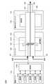
- FIG. 1is a schematic diagram schematically showing a first configuration example of a suction device.
- the suction device 100Aincludes a power supply unit 110, a cartridge 120, and a flavoring cartridge 130.
- the power supply unit 110includes a power supply unit 111A, a sensor unit 112A, a notification unit 113A, a storage unit 114A, a communication unit 115A, and a control unit 116A.
- the cartridge 120includes a heating unit 121A, a liquid guiding unit 122, and a liquid storage unit 123.
- the flavoring cartridge 130includes a flavor source 131 and a mouthpiece 124.
- An air flow path 180is formed in the cartridge 120 and the flavoring cartridge 130.
- the power supply unit 111Astores electric power. Then, the power supply unit 111A supplies electric power to each component of the suction device 100A based on the control by the control unit 116A.
- the power supply unit 111Amay be configured by, for example, a rechargeable battery such as a lithium ion secondary battery.
- the sensor unit 112Aacquires various information about the suction device 100A.
- the sensor unit 112Ais composed of a pressure sensor such as a microphone capacitor, a flow rate sensor, a temperature sensor, or the like, and acquires a value associated with suction by the user.
- the sensor unit 112Ais configured by an input device such as a button or a switch that receives input of information from the user.
- the notification unit 113Anotifies the user of the information.
- the notification unit 113Ais composed of, for example, a light emitting device that emits light, a display device that displays an image, a sound output device that outputs sound, a vibrating vibration device, and the like.
- the storage unit 114Astores various information for the operation of the suction device 100A.
- the storage unit 114Ais composed of a non-volatile storage medium such as a flash memory.
- the communication unit 115Ais a communication interface capable of performing communication conforming to any wired or wireless communication standard.
- a communication standardfor example, Wi-Fi (registered trademark), Bluetooth (registered trademark), or the like can be adopted.
- the control unit 116Afunctions as an arithmetic processing unit and a control device, and controls the overall operation in the suction device 100A according to various programs.
- the control unit 116Ais realized by, for example, an electronic circuit such as a CPU (Central Processing Unit) and a microprocessor.
- the liquid storage unit 123stores the aerosol source.
- the atomization of the aerosol sourceproduces an aerosol.
- Aerosol sourcesare, for example, polyhydric alcohols such as glycerin and propylene glycol, and liquids such as water. Aerosol sources may contain tobacco-derived or non-tobacco-derived flavor components.
- the suction device 100Ais a medical inhaler such as a nebulizer, the aerosol source may contain a drug.
- the liquid guiding unit 122guides and holds the aerosol source, which is the liquid stored in the liquid storage unit 123, from the liquid storage unit 123.
- the liquid guiding portion 122is a wick formed by twisting a fiber material such as glass fiber or a porous material such as a porous ceramic. In that case, the aerosol source stored in the liquid storage unit 123 is induced by the capillary effect of the wick.
- the heating unit 121Aheats the aerosol source to atomize the aerosol source and generate an aerosol.
- the heating unit 121Ais configured as a coil and is wound around the liquid induction unit 122.
- the heating unit 121Agenerates heat, the aerosol source held in the liquid induction unit 122 is heated and atomized to generate an aerosol.
- the heating unit 121Agenerates heat when power is supplied from the power supply unit 111A.
- powermay be supplied when the sensor unit 112A detects that the user has started suction and / or that predetermined information has been input. Then, when it is detected by the sensor unit 112A that the user has finished the suction and / or that the predetermined information has been input, the power supply may be stopped.
- the flavor source 131is a component for imparting a flavor component to the aerosol.
- the flavor source 131may contain a tobacco-derived or non-tobacco-derived flavor component.
- the air flow path 180is a flow path of air sucked by the user.
- the air flow path 180has a tubular structure having an air inflow hole 181 which is an inlet of air into the air flow path 180 and an air outflow hole 182 which is an outlet of air from the air flow path 180 at both ends.
- the liquid guiding portion 122is arranged on the upstream side (the side close to the air inflow hole 181), and the flavor source 131 is arranged on the downstream side (the side close to the air outflow hole 182).
- the air flowing in from the air inflow hole 181 due to the suction by the useris mixed with the aerosol generated by the heating unit 121A, and is transported to the air outflow hole 182 through the flavor source 131 as shown by the arrow 190.
- the flavor component contained in the flavor source 131is imparted to the aerosol.
- the mouthpiece 124is a member that can be held by the user during suction.
- An air outflow hole 182is arranged in the mouthpiece 124. The user can take in the mixed fluid of aerosol and air into the oral cavity by holding and sucking the mouthpiece 124.
- suction device 100Ahas been described above.
- the configuration of the suction device 100Ais not limited to the above, and various configurations exemplified below can be adopted.
- the suction device 100Adoes not have to include the flavoring cartridge 130.
- the cartridge 120is provided with the mouthpiece 124.
- the suction device 100Amay include a plurality of types of aerosol sources.
- a plurality of types of aerosols generated from a plurality of types of aerosol sourcesmay be mixed in the air flow path 180 to cause a chemical reaction, whereby another type of aerosol may be produced.
- the means for atomizing the aerosol sourceis not limited to heating by the heating unit 121A.
- the means for atomizing the aerosol sourcemay be oscillating atomization or induction heating.
- FIG. 2is a schematic diagram schematically showing a second configuration example of the suction device.
- the suction device 100Baccording to this configuration example includes a power supply unit 111B, a sensor unit 112B, a notification unit 113B, a storage unit 114B, a communication unit 115B, a control unit 116B, a heating unit 121B, a holding unit 140, and a holding unit 140. Includes insulation 144.
- Each of the power supply unit 111B, the sensor unit 112B, the notification unit 113B, the storage unit 114B, the communication unit 115B, and the control unit 116Bis substantially the same as the corresponding components included in the suction device 100A according to the first configuration example. Is.
- the holding portion 140has an internal space 141, and holds the stick-type base material 150 while accommodating a part of the stick-type base material 150 in the internal space 141.
- the holding portion 140has an opening 142 that communicates the internal space 141 to the outside, and holds the stick-type base material 150 inserted into the internal space 141 from the opening 142.
- the holding portion 140is a tubular body having an opening 142 and a bottom portion 143 as a bottom surface, and defines a columnar internal space 141.
- the holding portion 140also has a function of defining a flow path of air supplied to the stick-type base material 150.
- An air inflow holewhich is an inlet for air to such a flow path, is arranged, for example, at the bottom 143.
- the air outflow holewhich is an outlet for air from such a flow path, is an opening 142.
- the stick-type base material 150includes a base material portion 151 and a mouthpiece portion 152.
- the base material portion 151contains an aerosol source.
- the aerosol sourceis not limited to a liquid, but may be a solid.
- the heating unit 121Bhas the same configuration as the heating unit 121A according to the first configuration example. However, in the example shown in FIG. 2, the heating unit 121B is configured in a film shape and is arranged so as to cover the outer periphery of the holding unit 140. Then, when the heating unit 121B generates heat, the base material portion 151 of the stick-type base material 150 is heated from the outer periphery to generate an aerosol.
- the heat insulating portion 144prevents heat transfer from the heating portion 121B to other components.
- the heat insulating portion 144is made of a vacuum heat insulating material, an airgel heat insulating material, or the like.
- suction device 100Bhas been described above.
- the configuration of the suction device 100Bis not limited to the above, and various configurations exemplified below can be adopted.
- the heating portion 121Bmay be configured in a blade shape and may be arranged so as to project from the bottom portion 143 of the holding portion 140 to the internal space 141. In that case, the blade-shaped heating portion 121B is inserted into the base material portion 151 of the stick-type base material 150, and the base material portion 151 of the stick-type base material 150 is heated from the inside. As another example, the heating portion 121B may be arranged so as to cover the bottom portion 143 of the holding portion 140. Further, the heating unit 121B is a combination of two or more of a first heating unit that covers the outer periphery of the holding unit 140, a blade-shaped second heating unit, and a third heating unit that covers the bottom portion 143 of the holding unit 140. It may be configured as.
- the holding portion 140may include an opening / closing mechanism such as a hinge that opens / closes a part of the outer shell forming the internal space 141. Then, the holding portion 140 may sandwich the stick-type base material 150 inserted in the internal space 141 by opening and closing the outer shell.
- the heating unit 121Bmay be provided at the holding portion of the holding unit 140 and may be heated while pressing the stick-type base material 150.
- the means for atomizing the aerosol sourceis not limited to heating by the heating unit 121B.
- the means for atomizing the aerosol sourcemay be induction heating.
- the suction device 100Bmay further include a heating unit 121A, a liquid induction unit 122, a liquid storage unit 123, and an air flow path 180 according to the first configuration example, and the air flow path 180 air outflow hole 182. May also serve as an air inflow hole to the internal space 141.
- the mixed fluid of the aerosol and air generated by the heating unit 121Aflows into the internal space 141, is further mixed with the aerosol generated by the heating unit 121B, and reaches the user's oral cavity.
- FIG. 3is a diagram showing an example of the configuration of the sales system 1 according to the present embodiment.
- the sales system 1includes a suction device 100, a user terminal 200, a sales terminal 300, and a server 400.
- FIG. 3shows an example in which the sales system 1 has two suction devices 100 (100A and 100B), two user terminals 200 (200A and 200B), one sales terminal 300, and one server 400.
- the number of each device included in the sales system 1is not limited to such an example.
- the suction deviceis a device that produces a substance to be sucked by a user.
- the substance produced by the suction devicewill be described as being an aerosol.
- the substance produced by the suction devicemay be a gas.
- the user sucking the substance produced by the suction deviceis also referred to as "suction" or "puff".
- the suction device 100uses a base material to generate an aerosol that is sucked by the user.
- the heating unit 121is an example of a generation unit that produces an aerosol.
- the cartridge 120 and the flavor-imparting cartridge 130 in the first configuration example, and the stick-type base material 150 in the second configuration exampleare examples of the base material in the present invention.
- the suction device 100produces an aerosol using the base material attached to the suction device 100.
- the cartridge 120 and the flavoring cartridge 130 connected to the power supply unit 110are examples of the base material mounted on the suction device 100.
- the stick-type base material 150 inserted into the suction device 100is an example of the base material attached to the suction device 100.
- the suction device 100may take any configuration example from the first configuration example or the second configuration example described above.
- the suction device 100 used by the user Ais referred to as the suction device 100A
- the suction device 100 used by the user Bis referred to as the suction device 100B. That is, the configuration of the suction device 100A in FIG. 3 does not necessarily have to match the configuration shown in FIG. 1, and may, for example, match the configuration shown in FIG. Similarly, the configuration of the suction device 100B in FIG. 3 does not necessarily have to match the configuration shown in FIG. 2, and may, for example, match the configuration shown in FIG.
- the communication unit 115can perform wireless communication conforming to the short-range wireless communication standard of NFC (Near Field Communication) or Bluetooth (registered trademark).
- NFCNear Field Communication
- Bluetoothregistered trademark
- the user terminal 200is a terminal device used by the user of the suction device 100.
- the user terminal 200is composed of a smartphone, a tablet terminal, a wearable device, or the like.
- the suction device 100 and the user terminal 200 used by the same userare associated with each other.
- the userregisters the information of the suction device 100 in the user terminal 200, registers the information of the user terminal 200 in the suction device 100, and the suction device 100 and the user terminal 200 are used by the same user in the server 400. Register that.
- the configuration of the user terminal 200will be described with reference to FIG.
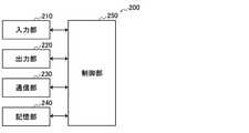
- FIG. 4is a block diagram showing an example of the configuration of the user terminal 200 according to the present embodiment.
- the user terminal 200includes an input unit 210, an output unit 220, a communication unit 230, a storage unit 240, and a control unit 250.
- the input unit 210has a function of accepting input of various information.
- the input unit 210may include an input device that receives input of information from the user. Examples of the input device include a button, a keyboard, a touch panel, a microphone, and the like.
- the input unit 210may include various sensors such as an image sensor.
- the output unit 220has a function of outputting information.
- the output unit 220may include an output device that outputs information to the user.
- Examples of the output deviceinclude a display device that displays information, a light emitting device that emits light, a vibrating vibration device, and a sound output device that outputs sound.
- An example of a display deviceis a display.
- An example of a light emitting deviceis an LED (Light Emitting Diode).
- An example of a vibrating deviceis an eccentric motor.
- An example of a sound output deviceis a speaker.
- the output unit 220notifies the user of the information by outputting the information input from the control unit 250.
- the communication unit 230is a communication interface for transmitting and receiving information between the user terminal 200 and other devices.
- the communication unit 230performs communication conforming to any wired or wireless communication standard.
- a communication standardfor example, a wireless LAN (Local Area Network), a wired LAN, Wi-Fi (registered trademark), Bluetooth (registered trademark), or the like can be adopted.
- the communication unit 230can perform wireless communication conforming to a short-range wireless communication standard such as NFC (Near Field Communication) or Bluetooth (registered trademark).
- the storage unit 240stores various information for the operation of the user terminal 200.
- the storage unit 240is composed of a non-volatile storage medium such as a flash memory.
- the control unit 250functions as an arithmetic processing unit and a control device, and controls the overall operation in the user terminal 200 according to various programs.
- the control unit 250is realized by, for example, an electronic circuit such as a CPU (Central Processing Unit) and a microprocessor.
- the control unit 250may include a ROM (Read Only Memory) for storing programs to be used, calculation parameters, and the like, and a RAM (Random Access Memory) for temporarily storing parameters and the like that change as appropriate.
- the user terminal 200executes various processes based on the control by the control unit 250.
- Processing of information input by the input unit 210, output of information by the output unit 220, transmission / reception of information by the communication unit 230, and storage and reading of information by the storage unit 240are examples of processing controlled by the control unit 250.
- Other processes executed by the user terminal 200, such as input of information to each component and processing based on the information output from each component,are also controlled by the control unit 250.
- the function of the control unit 250may be realized by using an application.
- the applicationmay be pre-installed or downloaded. Further, the function of the control unit 250 may be realized by PWA (Progressive Web Apps).
- the sales terminal 300is a terminal device that performs processing for selling a base material.
- the sales terminal 300may be configured as, for example, a cash register or a POS (Point Of Sales) terminal. In that case, the sales terminal 300 is installed in a store that sells the base material. Examples of the processing for selling the base material include accounting processing related to money transfer and sales management processing for registering the brand and quantity of the sold base material.
- the user who uses the sales terminal 300is typically a clerk.
- the sales terminal 300communicates with other devices in accordance with any wired or wireless communication standard.
- the sales terminal 300can perform wireless communication conforming to the short-range wireless communication standard of NFC (Near Field Communication) or Bluetooth (registered trademark).
- NFCNear Field Communication
- Bluetoothregistered trademark
- the server 400is an information processing device that provides various services related to the suction device 100.
- the server 400provides a membership service to the user of the suction device 100.
- the server 400collects and accumulates information of the suction device 100 (more accurately, information stored in the front panel 160 described later), analyzes the accumulated information, and provides a member service according to the analysis result. do.
- the usercan receive various member services such as providing information on the suction device 100 by accessing the server 400 and registering as a member in advance.
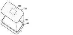
- FIG. 5is a diagram showing an example of an accessory attached to the suction device 100 according to the second configuration example of the present embodiment.
- the front panel 160may be detachably attached to the suction device 100.
- the front panel 160 and the back panel 162are joined so as to sandwich the suction device 100 between them to form an outer shell that covers the outer periphery of the suction device 100.
- the front panel 160is an example of an accessory.
- the front panel 160is provided with an NFC tag 161.
- the NFC tag 161has both a wireless communication function and a storage function, and information is read and written via wireless communication. Specifically, the NFC tag 161 performs wireless communication with the NFC reader / writer by NFC, transmits information to the NFC reader / writer, and stores the information received from the NFC reader / writer. Since NFC does not require pairing, it exhibits high usability when wirelessly communicating with an unspecified device.
- the user terminal 200manages the information stored in the front panel 160.
- the user terminal 200synchronizes with the NFC tag 161.
- the user terminal 200writes information in the NFC tag 161 so that the information stored in the NFC tag 161 matches the information stored in the user terminal 200, or reads and stores the information from the NFC tag 161. do.
- the information synchronized in this wayis also referred to as information to be synchronized below.
- the function of managing the information stored in the NFC tag 161can be realized by a dedicated application (hereinafter, also referred to as a management application).
- the information to be synchronizedincludes at least one of the information described below.
- the information to be synchronizedmay include the identification information of the base material.
- the base material identification informationis information for identifying the brand (that is, type) of the base material.
- the identification information of the base materialis also referred to as brand information.
- the user terminal 200may acquire brand information from a member service or a website provided from the server 400 and write it to the front panel 160.
- the user terminal 200may write the brand information acquired by applying image recognition to the captured image obtained by capturing the package of the base material on the front panel 160.
- the user terminal 200may acquire other information described below from the member service or the Web service and write it in the front panel 160.
- the information to be synchronizedmay include profile information indicating a profile that defines the operation of heating the substrate performed by the suction device 100 to generate an aerosol.
- the suction device 100heats the substrate according to the profile indicated by the profile information to produce an aerosol.
- the profile in the first configuration exampleis information that defines the feeding time to the heating unit 121A and the feeding amount (for example, voltage) per unit time.
- the control unit 116controls the power supply amount per unit time defined in the profile so as to be supplied from the power supply unit 111 to the heating unit 121A for the power supply time defined in the profile. Such power supply control is performed, for example, each time a puff is detected.
- the profile in the second configuration exampleis information that defines the relationship between the elapsed time from the start of heating by the heating unit 121B and the temperature of the heating unit 121B.
- the control unit 116controls the heating unit 121B so that the temperature change similar to the temperature change in the profile is realized in the heating unit 121B.
- the heating unit 121Bmay include a conductive track including a resistor, and the sensor unit 112 may detect the temperature of the heating unit 121B based on the electric resistance of the conductive track.
- the control of the heating unit 121Bcan be realized, for example, by controlling the power supply from the power supply unit 111 to the heating unit 121B.
- the power supplymay be controlled by, for example, PWM (Pulse Width Modulation) control.
- the profile informationmay be the profile itself.
- a profile that can be setmay be predetermined, such as provided by a member service.
- the profile informationmay be identification information indicating the profile. Since the amount of data of the identification information indicating the profile is smaller than that of the profile itself, the communication load when transmitting and receiving to and from other devices is reduced.
- the profilemay be customizable by the user, for example, the parameters such as the feeding time are adjusted by the user.
- the brand information and profile informationmay be associated with each other.
- the profile preferred by the usermay be different for each base material, and the brand information may be associated with a profile suitable for the base material of the brand indicated by the brand information. Therefore, as the information to be synchronized, the brand information and the profile information may be associated and transmitted / received. Further, the information to be synchronized may include identification information indicating a combination of brand information and profile information. By designing the data amount of the identification information indicating the combination of the brand information and the profile information to be smaller than the sum of the data amount of the brand information and the data amount of the profile information, the communication load when transmitting and receiving to and from other devices. Can be reduced. Table 1 below shows an example of identification information indicating a combination of brand information and profile information.
- the information to be synchronizedmay include the identification information of the suction device 100.
- the identification information of the suction device 100is information for uniquely identifying the suction device 100.
- the identification information of the suction device 100is also referred to as a device ID below.
- the information to be synchronizedmay include identification information of a user who uses the suction device 100.
- the user identification informationis information for uniquely identifying the user.
- the user identification informationis also referred to as a user ID below.
- the user IDmay be personal information such as a user's name, or may be an account name registered in the member service.
- the information to be synchronizedmay include authentication information.
- the authentication informationis information indicating that the user is entitled to purchase the base material.
- the authentication informationincludes, for example, information proving the age of the user.
- the sales terminal 300reads the information stored in the front panel 160 and performs various processes according to the read information.
- the sales terminal 300may perform a process for selling the base material according to the information received from the suction device 100.
- the sales terminal 300may perform a process of selling the base material of the brand indicated by the brand information received from the suction device 100 as the base material desired to be purchased by the user. According to such a configuration, the user can purchase the desired base material without verbally designating the desired base material to the clerk.
- the sales terminal 300transmits at least a part of the information received from the suction device 100 to the server 400.
- the server 400accumulates and analyzes the received information, and provides a member service according to the analysis result. Therefore, the user is a suitable member who reflects the purchasing behavior of the member only by purchasing the base material using the suction device 100, that is, without having to operate the user terminal 200 to transmit information to the server 400. You will be able to receive the service.
- the sales terminal 300may perform authentication based on the authentication information received from the suction device 100. For example, the sales terminal 300 determines the authentication success when the age of the user indicated by the authentication information is equal to or higher than a predetermined age, and determines the authentication failure in other cases. With such a configuration, it is possible to prevent the base material from being mistakenly sold to a user who is not qualified to purchase the base material.
- the server 400collects information stored in the front panel 160 via the sales terminal 300.
- the server 400accumulates the collected information, performs an analysis, and provides a member service based on the analysis result.
- the server 400may identify a large number of purchased brands, that is, brands that are popular among members, by aggregating the collected information for each brand information. Then, the server 400 may provide information recommending a brand that is popular among members as a member service.
- the server 400may identify a profile that is widely used, that is, a profile that is popular among members, by aggregating the collected information for each profile information. Then, the server 400 may provide information that recommends a profile that is popular among members as a member service.
- the sales terminal 300analyzes which brand of base material was sold to which user, that is, which user purchased which base material. You may.
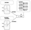
- FIG. 6is a diagram showing an example of the configuration of the dress-up system 10 according to the present embodiment.
- the dress-up system 10includes a user terminal 200 and a plurality of front panels 160.
- the dress-up system 10may also include a suction device 100 to which these plurality of front panels 160 are mounted.
- Each device included in the dress-up system 10is typically owned by the same user.
- Either the front panel 160A or the front panel 160Bmay be attached to the suction device 100. The user can change the front panel 160 to the suction device 100 according to the mood of the day, for example.
- the front panel 160Ato be exact, the NFC tag 161A
- the information stored in the front panel 160Bto be exact, the NFC tag 161B
- the brand information stored in the front panel 160A and the front panel 160Bis different and the user purchases the base material without recognizing it, the user can change the brand after the dressing and before the dressing. The base material will be purchased unintentionally.
- the user terminal 200stores information to be synchronized, which is information that should be stored in common by the plurality of front panels 160, and synchronizes with each of the plurality of front panels 160. That is, the user terminal 200 writes the information to be synchronized stored in the user terminal 200 to each of the plurality of front panels 160 via wireless communication.
- the storage unit 240stores the above-mentioned information to be synchronized as information to be stored in common by the plurality of front panels 160.
- the control unit 250controls a process of writing the information to be synchronized stored in the storage unit 240 to the front panel 160 via wireless communication by the communication unit 230.
- the writing processincludes establishing NFC communication with the NFC tag 161 and transmitting information to be synchronized.
- the user terminal 200writes common synchronization target information in both the NFC tag 161A and the NFC tag 161B.
- the information stored in the NFC tags 161 of the plurality of front panels 160is synchronized, so that the above-mentioned inconvenience can be avoided.
- the user terminal 200fronts the synchronization target information stored in the user terminal 200. Write to panel 160.
- the information stored in each of the plurality of front panels 160can be updated with the latest information.
- the user terminal 200uses the information stored in the front panel 160 as the synchronization target information. Acquire and memorize as. Information may be written to the front panel 160 from a device other than the user terminal 200 (for example, another user terminal 200 used by another user). In this respect, according to such a configuration, information written by another device can be synchronized by a plurality of front panels 160 as the latest information to be synchronized.
- the user terminal 200stores the information of the synchronization target and the time information indicating the time in association with each other, and writes the information of the synchronization target and the time information in association with each other in the front panel 160. Then, the user terminal 200 writes the synchronization target information stored in the user terminal 200 to the front panel 160 by comparing the time information stored in the user terminal 200 with the time information stored in the front panel 160. Judge whether or not. When the time indicated by the time information stored in the user terminal 200 and the time indicated by the time information stored in the front panel 160 match, it means that the latest information is written in the front panel 160. .. On the other hand, the difference between these times means that one of the synchronization target information stored in the user terminal 200 and the synchronization target information stored in the front panel 160 is newer than the other.
- the time indicated by the time information stored in the user terminal 200is newer than the time indicated by the time information stored in the front panel 160, that the old information is written in the front panel 160. Means. Therefore, the user terminal 200 writes the information of the synchronization target stored in the user terminal 200 to the front panel 160.
- the fact that the time indicated by the time information stored in the front panel 160 is newer than the time indicated by the time information stored in the user terminal 200means that new information is written in the front panel 160. .. Therefore, the user terminal 200 acquires and stores the synchronization target information stored in the front panel 160.
- the user terminal 200can update the information of the synchronization target stored in either the user terminal 200 or the front panel 160 to the latest, that is, can synchronize with the front panel 160.
- the time informationindicates the time when the information to be synchronized was acquired.
- the time information associated with the brand informationindicates the time when the user terminal 200 acquires the brand information from the website or the package.
- the timeis a concept including the date and time. According to such a configuration, the information newly acquired by the user terminal 200 can be stored in common to each of the plurality of front panels 160.
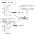
- FIG. 7is a diagram for explaining a specific example of the synchronization process according to the present embodiment.
- the front panel 160A(more accurately, the NFC tag 161A) and the front panel 160B (more accurately, the NFC tag 161B) use the brand information A as the time information "June 12, 12:00". Is stored in association with.
- the brand information Bis acquired from the website or the like at 12:00 on June 19, the user terminal 200 stores the brand information B in association with the time information "12:00 on June 19".
- the user terminal 200reads the brand information A and the time information "June 12 12:00" from the front panel 160A, the read time information "June 12 12:00" and the time information "6" are stored.
- the user terminal 200Compared with "12:00 on the 19th of the month", it is determined that the brand information B is newer. Therefore, the user terminal 200 writes the brand information B in association with the time information "June 19, 12:00" on the front panel 160A. The user terminal 200 performs the same processing on the front panel 160B.
- FIG. 8is a diagram for explaining a specific example of the synchronization process according to the present embodiment.
- This specific exampleis an example in which the brand information C is written to the front panel 160A by another user terminal 200 after the specific example shown in FIG. 7.
- the front panel 160A(more accurately, the NFC tag 161A) stores the brand information C in association with the time information “June 20, 12:00”.
- the front panel 160B(more accurately, the NFC tag 161B) stores the brand information B in association with the time information "June 19, 12:00”.
- the user terminal 200stores the brand information B in association with the time information "June 19, 12:00".
- the user terminal 200When the user terminal 200 reads the brand information C and the time information "June 20th 12:00" from the front panel 160A, the read time information "June 20th 12:00” and the time information "6" are stored. Compared with "12:00 on the 19th of the month", it is determined that the brand information C is newer. Therefore, the user terminal 200 stores the brand information C in association with the time information "June 20, 12:00". On the other hand, when the user terminal 200 reads the brand information B and the time information "12:00 on June 19" from the front panel 160B, the time information stored as the read time information "12:00 on June 19" is stored. Compared with "June 20, 12:00", it is determined that the brand information C is newer. Therefore, the user terminal 200 writes the brand information C in association with the time information "June 20, 12:00" on the front panel 160B.
- the user terminal 200stores the front panel 160 in which the synchronization target information stored in the user terminal 200 has been written. For example, the user terminal 200 stores whether or not the synchronization target information stored in the user terminal 200 has been written for each of the plurality of front panels 160. Then, the user terminal 200 writes the synchronization target information stored in the user terminal 200 to the front panel 160 in which the synchronization target information stored in the user terminal 200 is not yet written among the plurality of front panels 160. According to such a configuration, the information newly acquired by the user terminal 200 can be stored in common to each of the plurality of front panels 160.
- FIG. 9is a diagram for explaining a specific example of the synchronization process according to the present embodiment.
- the front panel 160A(more accurately, the NFC tag 161A) and the front panel 160B (more accurately, the NFC tag 161B) store the brand information A.
- the user terminal 200stores as a writing history that the brand information A has been written to each of the front panel 160A and the front panel 160B.
- FP_Aindicates the front panel 160A
- FP_Bindicates the front panel 160B.
- the user terminal 200When the user terminal 200 acquires the brand information B from a website or the like, the user terminal 200 stores the brand information B as information to be synchronized, and records that the brand information B is not written to the front panel 160A and the front panel 160B as a writing history.
- the user terminal 200writes the brand information B to the front panel 160A and stores the fact that the brand information B has been written to the front panel 160A as a writing history.
- the user terminal 200performs the same processing on the front panel 160B.
- FIG. 10is a diagram for explaining a specific example of the synchronization process according to the present embodiment.
- This specific exampleis an example in which the brand information C is written to the front panel 160A by another user terminal 200 after the specific example shown in FIG.
- the front panel 160A(more accurately, the NFC tag 161A) stores the brand information C.
- the front panel 160B(more accurately, the NFC tag 161B) stores the brand information B.
- the user terminal 200stores as a writing history that the brand information A and the brand information B have been written to each of the front panel 160A and the front panel 160B.
- the user terminal 200determines that the brand information C is newly written information from another user terminal 200 based on the fact that the brand information C is not included in the writing history. do. Therefore, the user terminal 200 stores the brand information C as the information to be synchronized, and indicates that the brand information C has already been written to the front panel 160A and that the brand information C has not been written to the front panel 160B. Store as write history. Then, the user terminal 200 writes the brand information C to the front panel 160B and stores the fact that the brand information C has been written to the front panel 160B as a writing history.
- the user terminal 200synchronizes with the front panel 160 for which NFC communication has been established with the user terminal 200 among the plurality of front panels 160. In other words, the user terminal 200 synchronizes with the front panel 160 at the timing when NFC communication is established with the front panel 160. For example, the user can execute synchronization between the user terminal 200 and the front panel 160 by holding the user terminal 200 over the front panel 160.
- the user terminal 200may write the synchronization target information stored in the user terminal 200 to the front panel 160 mounted on the suction device 100 among the plurality of front panels 160.
- the user terminal 200may synchronize with the front panel 160 at the timing when the front panel 160 is attached to the suction device 100. According to such a configuration, since synchronization is executed for the front panel 160 mounted on the suction device 100, unnecessary synchronization such as avoiding synchronization with other front panels 160 that have not been used for a long period of time is performed. It becomes possible to avoid it.
- the user terminal 200identifies the front panel 160 mounted on the suction device 100 and synchronizes only with the identified front panel 160.
- the sensor unit 112may identify the front panel 160 mounted on the suction device 100 based on the electrical resistance.
- the suction device 100transmits the identification result of the front panel 160 to the user terminal 200 by the communication unit 115.
- the user terminal 200can synchronize only with the front panel 160 identified by the received information.
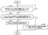
- FIG. 11is a flowchart for explaining an example of the flow of synchronous processing executed in the user terminal 200 according to the present embodiment.
- the user terminal 200determines whether or not NFC communication has been established with any of the plurality of front panels 160 belonging to the dress-up system 10 (step S102).
- step S102NO
- the user terminal 200waits until NFC communication is established.
- step S102when it is determined that NFC communication has been established (step S102: YES), the synchronization target information read from the front panel 160 of the user terminal 200 is the synchronization target information stored in the user terminal 200. It is determined whether or not it is newer (step S104).
- step S104When it is determined that the synchronization target information read from the front panel 160 is newer (step S104: YES), the user terminal 200 stores the read synchronization target information (step S106).
- step S104when it is determined that the synchronization target information stored in the user terminal 200 is newer (step S104: NO), the user terminal 200 uses the synchronization target information stored in the user terminal 200 on the front panel 160. (Step S108).
- the user terminal 200stores one type of synchronization target information and writes it in common to a plurality of front panels 160
- the user terminal 200may store a plurality of types of synchronization target information. Then, the user terminal 200 may write, for example, one type of synchronization target information selected by the user in common to the plurality of front panels 160. Further, each of the plurality of front panels 160 belonging to the dress-up system 10 may be classified into any of a plurality of groups. In that case, the user terminal 200 stores information to be synchronized for each group.
- the user terminal 200writes the information of the synchronization target to be commonly stored by the plurality of front panels 160 belonging to the same group to the front panel 160 belonging to the group.
- the user terminal 200stores private synchronization target information and work synchronization target information.
- the user terminal 200writes the information of the synchronization target for private use for each of the plurality of private front panels 160, and synchronizes the work for each of the front panels 160 for work. Write the information of. According to such a configuration, it is possible to improve usability when a plurality of front panels 160 are used properly for each application.
- the present inventionis not limited to such an example.
- the present inventionis applicable to any accessory having a communication function and a storage function.
- the accessorymay be equipped with a communication function conforming to a wireless communication standard other than NFC.
- An example of another wireless communication standardis Bluetooth.
- the front panel 160is exemplified as an accessory attached to the suction device 100, but the present invention is not limited to this example.
- the accessorymay have any configuration such as a strap and a seal that can be attached to and detached from the suction device 100.
- an accessorysuch as a smartphone case may be detachably attached to the smartphone. Then, the control of the smartphone may be switched by using the attachment / detachment of the accessory as a trigger.
- each device described in the present specificationmay be realized by using any of software, hardware, and a combination of software and hardware.
- the programs constituting the softwareare stored in advance in, for example, a recording medium (non-transitory media) provided inside or outside each device. Then, each program is read into RAM at the time of execution by a computer and executed by a processor such as a CPU.
- the recording mediumis, for example, a magnetic disk, an optical disk, a magneto-optical disk, a flash memory, or the like.
- the above computer programmay be distributed, for example, via a network without using a recording medium.
- the following configurationsalso belong to the technical scope of the present invention.
- Multiple accessoriesthat can be attached to and detached from a suction device that uses a substrate to generate an aerosol that is sucked by the user, and that can read and write information via wireless communication.
- a terminal devicethat stores information to be synchronized, which is information that should be stored in common by the plurality of accessories, and writes the stored information of the synchronization target to each of the plurality of accessories via wireless communication.
- a system equipped with(2) When the information of the synchronization target stored in the terminal device is newer than the information of the synchronization target stored in the accessory, the terminal device stores the information of the synchronization target stored in the terminal device. To the accessory, The system according to (1) above.
- the terminal devicesets the information stored in the accessory as the synchronization target. Acquire and memorize as information, The system according to (1) or (2) above.
- the terminal devicestores the information of the synchronization target and the time information indicating the time in association with each other, and writes the information of the synchronization target and the time information in association with the accessory. By comparing the time information stored in the terminal device with the time information stored in the accessory, it is determined whether or not to write the synchronization target information stored in the terminal device to the accessory. , The system according to (2) or (3) above. (5) The time information indicates the time when the information to be synchronized is acquired.
- the terminal devicestores the accessory in which the information of the synchronization target stored in the terminal device has been written, and the information of the synchronization target stored in the terminal device among the plurality of the accessories is still written. Write the synchronization target information stored in the terminal device to the accessory.
- the terminal devicewrites the information of the synchronization target stored in the terminal device to the accessory attached to the suction device among the plurality of accessories.
- Each of the plurality of accessoriesis classified into one of a plurality of groups and is classified into one of a plurality of groups.
- the terminal devicewrites the information of the synchronization target to be commonly stored by the plurality of accessories belonging to the same group to the accessories belonging to the group.
- the accessoryincludes an NFC tag that reads and writes information via wireless communication.
- the information to be synchronizedincludes the identification information of the base material.
- the synchronization target informationincludes at least one of the identification information of the suction device and the identification information of the user who uses the suction device.
- the synchronization target informationincludes profile information indicating a profile defining the operation of the suction device to heat the substrate to generate the aerosol.
- the systemaccording to any one of (1) to (11) above.
- a communication unitthat performs wireless communication with other devices, Information to be synchronized, which is information that should be stored in common by multiple accessories that can be attached to and detached from a suction device that uses a base material to generate an aerosol that is sucked by the user and that reads and writes information via wireless communication.
- a storage unitto memorize and A control unit that controls a process of writing the synchronization target information stored in the storage unit to each of the plurality of accessories via wireless communication by the communication unit.
- Information to be synchronizedwhich is information that should be stored in common by multiple accessories that can be attached to and detached from a suction device that uses a base material to generate an aerosol that is sucked by the user and that reads and writes information via wireless communication. Controlling the process of writing to each of the plurality of accessories via wireless communication, Control method including.
- a computerthat controls a terminal device that performs wireless communication with other devices
- Information to be synchronizedwhich is information that should be stored in common by multiple accessories that can be attached to and detached from a suction device that uses a base material to generate an aerosol that is sucked by the user and that reads and writes information via wireless communication.
- a control unitthat controls the process of writing to each of the plurality of accessories via wireless communication.
- Sales system100 Suction device 110 Power supply unit 111 Power supply unit 112 Sensor unit 113 Notification unit 114 Storage unit 115 Communication unit, Main unit communication unit 116 Control unit 120 Cartridge 121 Heating unit 122 Liquid induction unit 123 Liquid storage unit 124 Mouthpiece 130 Flavoring Cartridge 131 Flavor source 140 Retaining part 141 Internal space 142 Opening 143 Bottom part 144 Insulation part 150 Stick type base material 151 Base material part 152 Mouthpiece 160 Front panel 161 NFC tag 162 Back panel 180 Air flow path 181 Air inflow hole 182 Air outflow hole 200 User terminal 300 Sales terminal 400 Server
Landscapes
- Business, Economics & Management (AREA)
- Engineering & Computer Science (AREA)
- Finance (AREA)
- Accounting & Taxation (AREA)
- Physics & Mathematics (AREA)
- Development Economics (AREA)
- Theoretical Computer Science (AREA)
- General Physics & Mathematics (AREA)
- General Business, Economics & Management (AREA)
- Strategic Management (AREA)
- Marketing (AREA)
- Economics (AREA)
- Health & Medical Sciences (AREA)
- Animal Behavior & Ethology (AREA)
- Life Sciences & Earth Sciences (AREA)
- Biomedical Technology (AREA)
- Veterinary Medicine (AREA)
- Public Health (AREA)
- General Health & Medical Sciences (AREA)
- Anesthesiology (AREA)
- Heart & Thoracic Surgery (AREA)
- Hematology (AREA)
- Computer Networks & Wireless Communication (AREA)
- Pulmonology (AREA)
- Bioinformatics & Cheminformatics (AREA)
- Entrepreneurship & Innovation (AREA)
- Information Transfer Between Computers (AREA)
- Control Of Vending Devices And Auxiliary Devices For Vending Devices (AREA)
Abstract
Description
Translated fromJapanese本発明は、システム、端末装置、制御方法、及びプログラムに関する。The present invention relates to a system, a terminal device, a control method, and a program.
電子タバコ及びネブライザ等の、ユーザに吸引される物質を生成する吸引装置が広く普及している。例えば、吸引装置は、エアロゾルを生成するためのエアロゾル源、及び生成されたエアロゾルに香味成分を付与するための香味源等を含む基材を用いて、香味成分が付与されたエアロゾルを生成する。ユーザは、吸引装置により生成された、香味成分が付与されたエアロゾルを吸引することで、香味を味わうことができる。Suction devices that generate substances that are sucked by users, such as electronic cigarettes and nebulizers, are widely used. For example, the suction device uses a substrate containing an aerosol source for producing an aerosol, a flavor source for imparting a flavor component to the produced aerosol, and the like to generate an aerosol to which the flavor component is added. The user can taste the flavor by sucking the aerosol to which the flavor component is added, which is generated by the suction device.
近年では、吸引装置に関する情報を無線で送受信することで、吸引装置に関する各種のサービスを提供することが検討されている。例えば、下記特許文献1では、基材を販売する店舗側の端末が、スマートフォン等のユーザ端末から購入希望の基材の識別情報を無線で受信し、受信した識別情報に基づいて陳列棚における購入希望の基材の位置を特定する技術が開示されている。In recent years, it has been considered to provide various services related to the suction device by wirelessly transmitting and receiving information about the suction device. For example, in
また、下記特許文献2では、通信機能を有さない吸引装置に、通信機能付きのアクセサリを装着して、アクセサリを介して吸引装置と他の装置との間で通信を行う技術が開示されている。Further, Patent Document 2 below discloses a technique in which an accessory with a communication function is attached to a suction device having no communication function, and communication is performed between the suction device and another device via the accessory. There is.
ユーザが、複数のアクセサリを所有し、複数のアクセサリを吸引装置に付け替えながら使用することが考えられる。そのようなユースケースについては、上記特許文献においてなんら考慮されていなかった。It is conceivable that the user owns multiple accessories and uses them while replacing the multiple accessories with the suction device. No such use case was considered in the above patent document.
そこで、本発明は、上記問題に鑑みてなされたものであり、本発明の目的とするところは、複数のアクセサリが吸引装置に付け替えられる場合に生じ得る不都合を回避することが可能な仕組みを提供することにある。Therefore, the present invention has been made in view of the above problems, and an object of the present invention is to provide a mechanism capable of avoiding inconveniences that may occur when a plurality of accessories are replaced with suction devices. To do.
上記課題を解決するために、本発明のある観点によれば、基材を用いてユーザに吸引されるエアロゾルを生成する吸引装置に着脱可能であり、無線通信を介して情報を読み書きされる複数のアクセサリと、複数の前記アクセサリが共通して記憶するべき情報である同期対象の情報を記憶し、記憶された前記同期対象の情報を、無線通信を介して複数の前記アクセサリの各々に書き込む端末装置と、を備えるシステムが提供される。In order to solve the above problems, according to a certain aspect of the present invention, a plurality of devices that can be attached to and detached from a suction device that generates an aerosol that is sucked by a user using a base material and that can read and write information via wireless communication. A terminal that stores information to be synchronized, which is information that should be commonly stored by the accessory and the plurality of accessories, and writes the stored information of the synchronization target to each of the plurality of accessories via wireless communication. A device and a system are provided.
前記端末装置は、前記端末装置に記憶された前記同期対象の情報の方が、前記アクセサリに記憶された前記同期対象の情報よりも新しい場合に、前記端末装置に記憶された前記同期対象の情報を前記アクセサリに書き込んでもよい。When the information of the synchronization target stored in the terminal device is newer than the information of the synchronization target stored in the accessory, the terminal device stores the information of the synchronization target stored in the terminal device. May be written in the accessory.
前記端末装置は、前記アクセサリに記憶された前記同期対象の情報の方が、前記端末装置に記憶された前記同期対象の情報よりも新しい場合に、前記アクセサリに記憶された情報を前記同期対象の情報として取得し記憶してもよい。When the information of the synchronization target stored in the accessory is newer than the information of the synchronization target stored in the terminal device, the terminal device sets the information stored in the accessory as the synchronization target. It may be acquired and stored as information.
前記端末装置は、前記同期対象の情報と時刻を示す時刻情報とを対応付けて記憶し、前記同期対象の情報と前記時刻情報とを対応付けて前記アクセサリに書き込み、前記端末装置に記憶された前記時刻情報と前記アクセサリに記憶された前記時刻情報とを比較することで、前記端末装置に記憶された前記同期対象の情報を前記アクセサリに書き込むか否かを判定してもよい。The terminal device stores the information of the synchronization target and the time information indicating the time in association with each other, writes the information of the synchronization target and the time information in association with the accessory, and stores the information in the terminal device. By comparing the time information with the time information stored in the accessory, it may be determined whether or not to write the synchronization target information stored in the terminal device to the accessory.
前記時刻情報は、前記同期対象の情報が取得された時刻を示してもよい。The time information may indicate the time when the information to be synchronized is acquired.
前記端末装置は、前記端末装置に記憶された前記同期対象の情報を書き込み済みの前記アクセサリを記憶し、複数の前記アクセサリのうち前記端末装置に記憶された前記同期対象の情報がまだ書き込まれていない前記アクセサリに、前記端末装置に記憶された前記同期対象の情報を書き込んでもよい。The terminal device stores the accessory in which the information of the synchronization target stored in the terminal device has been written, and the information of the synchronization target stored in the terminal device among the plurality of the accessories is still written. The information to be synchronized may be written in the accessory which is not stored in the terminal device.
前記端末装置は、複数の前記アクセサリのうち、前記吸引装置に装着された前記アクセサリに、前記端末装置に記憶された前記同期対象の情報を書き込んでもよい。The terminal device may write the information of the synchronization target stored in the terminal device to the accessory attached to the suction device among the plurality of accessories.
複数の前記アクセサリの各々は複数のグループのいずれかに分類され、前記端末装置は、同一グループに属する複数の前記アクセサリが共通して記憶するべき前記同期対象の情報を、当該グループに属するアクセサリに書き込んでもよい。Each of the plurality of accessories is classified into one of a plurality of groups, and the terminal device transfers the information of the synchronization target to be commonly stored by the plurality of accessories belonging to the same group to the accessories belonging to the group. You may write.
前記アクセサリは、無線通信を介して情報を読み書きされるNFCタグを含んでもよい。The accessory may include an NFC tag for reading and writing information via wireless communication.
前記同期対象の情報は、前記基材の識別情報を含んでもよい。The information to be synchronized may include identification information of the base material.
前記同期対象の情報は、前記吸引装置の識別情報、又は前記吸引装置を使用する前記ユーザの識別情報の少なくともいずれかを含んでもよい。The information to be synchronized may include at least one of the identification information of the suction device and the identification information of the user who uses the suction device.
前記同期対象の情報は、前記吸引装置が前記エアロゾルを生成するために行う前記基材を加熱する動作を規定するプロファイルを示すプロファイル情報を含んでもよい。The information to be synchronized may include profile information indicating a profile defining the operation of heating the substrate performed by the suction device to generate the aerosol.
また、上記課題を解決するために、本発明の別の観点によれば、他の装置との間で無線通信を行う通信部と、基材を用いてユーザに吸引されるエアロゾルを生成する吸引装置に着脱可能であり、無線通信を介して情報を読み書きされる複数のアクセサリが共通して記憶するべき情報である同期対象の情報を記憶する記憶部と、前記記憶部に記憶された前記同期対象の情報を、前記通信部による無線通信を介して複数の前記アクセサリの各々に書き込む処理を制御する制御部と、を備える端末装置が提供される。Further, in order to solve the above problems, according to another aspect of the present invention, a communication unit that performs wireless communication with another device and suction that generates an aerosol that is sucked by the user using a base material. A storage unit that stores information to be synchronized, which is information that can be attached to and detached from the device and is information that should be commonly stored by a plurality of accessories that read and write information via wireless communication, and the synchronization stored in the storage unit. A terminal device including a control unit that controls a process of writing target information to each of the plurality of accessories via wireless communication by the communication unit is provided.
また、上記課題を解決するために、本発明の別の観点によれば、他の装置との間で無線通信を行う端末装置により実行される制御方法であって、基材を用いてユーザに吸引されるエアロゾルを生成する吸引装置に着脱可能であり、無線通信を介して情報を読み書きされる複数のアクセサリが共通して記憶するべき情報である同期対象の情報を、無線通信を介して複数の前記アクセサリの各々に書き込む処理を制御すること、を含む制御方法が提供される。Further, in order to solve the above-mentioned problems, according to another aspect of the present invention, it is a control method executed by a terminal device that performs wireless communication with another device, and is a control method executed by a user using a base material. Multiple accessories to be attached to and detached from the suction device that generates the sucked aerosol, and information to be synchronized, which is information that should be commonly stored by multiple accessories that read and write information via wireless communication, are stored via wireless communication. A control method is provided that includes controlling the process of writing to each of the accessories.
また、上記課題を解決するために、本発明の別の観点によれば、他の装置との間で無線通信を行う端末装置を制御するコンピュータを、基材を用いてユーザに吸引されるエアロゾルを生成する吸引装置に着脱可能であり、無線通信を介して情報を読み書きされる複数のアクセサリが共通して記憶するべき情報である同期対象の情報を、無線通信を介して複数の前記アクセサリの各々に書き込む処理を制御する制御部、として機能させるためのプログラムが提供される。Further, in order to solve the above problems, according to another aspect of the present invention, an aerosol that is sucked by a user using a base material for a computer that controls a terminal device that performs wireless communication with another device. Information to be synchronized, which is information that should be stored in common by multiple accessories that can be attached to and detached from the suction device that generates the information and is read / written via wireless communication. A program for functioning as a control unit that controls the process of writing to each is provided.
以上説明したように本発明によれば、複数のアクセサリが吸引装置に付け替えられる場合に生じ得る不都合を回避することが可能な仕組みが提供される。As described above, according to the present invention, there is provided a mechanism capable of avoiding the inconvenience that may occur when a plurality of accessories are replaced with a suction device.
以下に添付図面を参照しながら、本発明の好適な実施の形態について詳細に説明する。なお、本明細書及び図面において、実質的に同一の機能構成を有する構成要素については、同一の符号を付することにより重複説明を省略する。A preferred embodiment of the present invention will be described in detail with reference to the accompanying drawings below. In the present specification and the drawings, components having substantially the same functional configuration are designated by the same reference numerals, so that duplicate description will be omitted.
また、本明細書及び図面において、実質的に同一の機能構成を有する要素を、同一の符号の後に異なるアルファベットを付して区別する場合もある。例えば、実質的に同一の機能構成を有する複数の要素を、必要に応じて吸引装置100A、及び100Bのように区別する。ただし、実質的に同一の機能構成を有する複数の要素の各々を特に区別する必要がない場合、同一符号のみを付する。例えば、吸引装置100A、及び100Bを特に区別する必要が無い場合には、単に吸引装置100と称する。Further, in the present specification and the drawings, elements having substantially the same functional configuration may be distinguished by adding different alphabets after the same reference numerals. For example, a plurality of elements having substantially the same functional configuration are distinguished as needed, such as
<<1.吸引装置の構成例>>
吸引装置は、ユーザにより吸引される物質を生成する装置である。以下では、吸引装置により生成される物質が、エアロゾルであるものとして説明する。他に、吸引装置により生成される物質は、気体であってもよい。<< 1. Configuration example of suction device >>
The suction device is a device that produces a substance that is sucked by the user. In the following, the substance produced by the suction device will be described as being an aerosol. Alternatively, the substance produced by the suction device may be a gas.
(1)第1の構成例
図1は、吸引装置の第1の構成例を模式的に示す模式図である。図1に示すように、本構成例に係る吸引装置100Aは、電源ユニット110、カートリッジ120、及び香味付与カートリッジ130を含む。電源ユニット110は、電源部111A、センサ部112A、通知部113A、記憶部114A、通信部115A、及び制御部116Aを含む。カートリッジ120は、加熱部121A、液誘導部122、及び液貯蔵部123を含む。香味付与カートリッジ130は、香味源131、及びマウスピース124を含む。カートリッジ120及び香味付与カートリッジ130には、空気流路180が形成される。(1) First Configuration Example FIG. 1 is a schematic diagram schematically showing a first configuration example of a suction device. As shown in FIG. 1, the
電源部111Aは、電力を蓄積する。そして、電源部111Aは、制御部116Aによる制御に基づいて、吸引装置100Aの各構成要素に電力を供給する。電源部111Aは、例えば、リチウムイオン二次電池等の充電式バッテリにより構成され得る。The
センサ部112Aは、吸引装置100Aに関する各種情報を取得する。一例として、センサ部112Aは、マイクロホンコンデンサ等の圧力センサ、流量センサ又は温度センサ等により構成され、ユーザによる吸引に伴う値を取得する。他の一例として、センサ部112Aは、ボタン又はスイッチ等の、ユーザからの情報の入力を受け付ける入力装置により構成される。The
通知部113Aは、情報をユーザに通知する。通知部113Aは、例えば、発光する発光装置、画像を表示する表示装置、音を出力する音出力装置、又は振動する振動装置等により構成される。The
記憶部114Aは、吸引装置100Aの動作のための各種情報を記憶する。記憶部114Aは、例えば、フラッシュメモリ等の不揮発性の記憶媒体により構成される。The
通信部115Aは、有線又は無線の任意の通信規格に準拠した通信を行うことが可能な通信インタフェースである。かかる通信規格としては、例えば、Wi-Fi(登録商標)、又はBluetooth(登録商標)等が採用され得る。The
制御部116Aは、演算処理装置及び制御装置として機能し、各種プログラムに従って吸引装置100A内の動作全般を制御する。制御部116Aは、例えばCPU(Central Processing Unit)、及びマイクロプロセッサ等の電子回路によって実現される。The
液貯蔵部123は、エアロゾル源を貯蔵する。エアロゾル源が霧化されることで、エアロゾルが生成される。エアロゾル源は、例えば、グリセリン及びプロピレングリコール等の多価アルコール、並びに水等の液体である。エアロゾル源は、たばこ由来又は非たばこ由来の香味成分を含んでいてもよい。吸引装置100Aがネブライザ等の医療用吸入器である場合、エアロゾル源は、薬剤を含んでもよい。The
液誘導部122は、液貯蔵部123に貯蔵された液体であるエアロゾル源を、液貯蔵部123から誘導し、保持する。液誘導部122は、例えば、ガラス繊維等の繊維素材又は多孔質状のセラミック等の多孔質状素材を撚って形成されるウィックである。その場合、液貯蔵部123に貯蔵されたエアロゾル源は、ウィックの毛細管効果により誘導される。The
加熱部121Aは、エアロゾル源を加熱することで、エアロゾル源を霧化してエアロゾルを生成する。図1に示した例では、加熱部121Aは、コイルとして構成され、液誘導部122に巻き付けられる。加熱部121Aが発熱すると、液誘導部122に保持されたエアロゾル源が加熱されて霧化され、エアロゾルが生成される。加熱部121Aは、電源部111Aから給電されると発熱する。一例として、ユーザが吸引を開始したこと、及び/又は所定の情報が入力されたことが、センサ部112Aにより検出された場合に、給電されてもよい。そして、ユーザが吸引を終了したこと、及び/又は所定の情報が入力されたことが、センサ部112Aにより検出された場合に、給電が停止されてもよい。The
香味源131は、エアロゾルに香味成分を付与するための構成要素である。香味源131は、たばこ由来又は非たばこ由来の香味成分を含んでいてもよい。The
空気流路180は、ユーザに吸引される空気の流路である。空気流路180は、空気流路180内への空気の入り口である空気流入孔181と、空気流路180からの空気の出口である空気流出孔182と、を両端とする管状構造を有する。空気流路180の途中には、上流側(空気流入孔181に近い側)に液誘導部122が配置され、下流側(空気流出孔182に近い側)に香味源131が配置される。ユーザによる吸引に伴い空気流入孔181から流入した空気は、加熱部121Aにより生成されたエアロゾルと混合され、矢印190に示すように、香味源131を通過して空気流出孔182へ輸送される。エアロゾルと空気との混合流体が香味源131を通過する際には、香味源131に含まれる香味成分がエアロゾルに付与される。The
マウスピース124は、吸引の際にユーザに咥えられる部材である。マウスピース124には、空気流出孔182が配置される。ユーザは、マウスピース124を咥えて吸引することで、エアロゾルと空気との混合流体を口腔内へ取り込むことができる。The
以上、吸引装置100Aの構成例を説明した。もちろん吸引装置100Aの構成は上記に限定されず、以下に例示する多様な構成をとり得る。The configuration example of the
一例として、吸引装置100Aは、香味付与カートリッジ130を含んでいなくてもよい。その場合、カートリッジ120にマウスピース124が設けられる。As an example, the
他の一例として、吸引装置100Aは、複数種類のエアロゾル源を含んでいてもよい。複数種類のエアロゾル源から生成された複数種類のエアロゾルが空気流路180内で混合され化学反応を起こすことで、さらに他の種類のエアロゾルが生成されてもよい。As another example, the
また、エアロゾル源を霧化する手段は、加熱部121Aによる加熱に限定されない。例えば、エアロゾル源を霧化する手段は、振動霧化、又は誘導加熱であってもよい。Further, the means for atomizing the aerosol source is not limited to heating by the
(2)第2の構成例
図2は、吸引装置の第2の構成例を模式的に示す模式図である。図2に示すように、本構成例に係る吸引装置100Bは、電源部111B、センサ部112B、通知部113B、記憶部114B、通信部115B、制御部116B、加熱部121B、保持部140、及び断熱部144を含む。(2) Second Configuration Example FIG. 2 is a schematic diagram schematically showing a second configuration example of the suction device. As shown in FIG. 2, the
電源部111B、センサ部112B、通知部113B、記憶部114B、通信部115B、及び制御部116Bの各々は、第1の構成例に係る吸引装置100Aに含まれる対応する構成要素と実質的に同一である。Each of the
保持部140は、内部空間141を有し、内部空間141にスティック型基材150の一部を収容しながらスティック型基材150を保持する。保持部140は、内部空間141を外部に連通する開口142を有し、開口142から内部空間141に挿入されたスティック型基材150を保持する。例えば、保持部140は、開口142及び底部143を底面とする筒状体であり、柱状の内部空間141を画定する。保持部140は、スティック型基材150へ供給される空気の流路を画定する機能も有する。かかる流路への空気の入り口である空気流入孔は、例えば底部143に配置される。他方、かかる流路からの空気の出口である空気流出孔は、開口142である。The holding
スティック型基材150は、基材部151、及び吸口部152を含む。基材部151は、エアロゾル源を含む。なお、本構成例において、エアロゾル源は液体に限られるものではなく、固体であってもよい。スティック型基材150が保持部140に保持された状態において、基材部151の少なくとも一部は内部空間141に収容され、吸口部152の少なくとも一部は開口142から突出する。そして、開口142から突出した吸口部152をユーザが咥えて吸引すると、図示しない空気流入孔から内部空間141に空気が流入し、基材部151から発生するエアロゾルと共にユーザの口内に到達する。The stick-
加熱部121Bは、第1の構成例に係る加熱部121Aと同様の構成を有する。ただし、図2に示した例では、加熱部121Bは、フィルム状に構成され、保持部140の外周を覆うように配置される。そして、加熱部121Bが発熱すると、スティック型基材150の基材部151が外周から加熱され、エアロゾルが生成される。The
断熱部144は、加熱部121Bから他の構成要素への伝熱を防止する。例えば、断熱部144は、真空断熱材、又はエアロゲル断熱材等により構成される。The
以上、吸引装置100Bの構成例を説明した。もちろん吸引装置100Bの構成は上記に限定されず、以下に例示する多様な構成をとり得る。The configuration example of the
一例として、加熱部121Bは、ブレード状に構成され、保持部140の底部143から内部空間141に突出するように配置されてもよい。その場合、ブレード状の加熱部121Bは、スティック型基材150の基材部151に挿入され、スティック型基材150の基材部151を内部から加熱する。他の一例として、加熱部121Bは、保持部140の底部143を覆うように配置されてもよい。また、加熱部121Bは、保持部140の外周を覆う第1の加熱部、ブレード状の第2の加熱部、及び保持部140の底部143を覆う第3の加熱部のうち、2以上の組み合わせとして構成されてもよい。As an example, the
他の一例として、保持部140は、内部空間141を形成する外殻の一部を開閉する、ヒンジ等の開閉機構を含んでいてもよい。そして、保持部140は、外殻を開閉することで、内部空間141に挿入されたスティック型基材150を挟持してもよい。その場合、加熱部121Bは、保持部140における当該挟持箇所に設けられ、スティック型基材150を押圧しながら加熱してもよい。As another example, the holding
また、エアロゾル源を霧化する手段は、加熱部121Bによる加熱に限定されない。例えば、エアロゾル源を霧化する手段は、誘導加熱であってもよい。Further, the means for atomizing the aerosol source is not limited to heating by the
また、吸引装置100Bは、第1の構成例に係る加熱部121A、液誘導部122、液貯蔵部123、及び空気流路180をさらに含んでいてもよく、空気流路180の空気流出孔182が内部空間141への空気流入孔を兼ねていてもよい。この場合、加熱部121Aにより生成されたエアロゾルと空気との混合流体は、内部空間141に流入して加熱部121Bにより生成されたエアロゾルとさらに混合され、ユーザの口腔内に到達する。Further, the
<<2.技術的特徴>>
<2.1.システム構成例>
図3は、本実施形態に係る販売システム1の構成の一例を示す図である。図3に示すように、販売システム1は、吸引装置100、ユーザ端末200、販売端末300及びサーバ400を含む。なお、図3では、販売システム1が、2つの吸引装置100(100A及び100B)、2つのユーザ端末200(200A及び200B)、1つの販売端末300、及び1つのサーバ400を有する例を示しているが、販売システム1に含まれる各装置の個数はかかる例に限定されない。<< 2. Technical features >>
<2.1. System configuration example>
FIG. 3 is a diagram showing an example of the configuration of the
(1)吸引装置100の構成
吸引装置は、ユーザにより吸引される物質を生成する装置である。以下では、吸引装置により生成される物質が、エアロゾルであるものとして説明する。他に、吸引装置により生成される物質は、気体であってもよい。以下では、吸引装置により生成された物質をユーザが吸引することを、「吸引」又は「パフ」とも称する。(1) Configuration of
本実施形態に係る吸引装置100は、基材を用いてユーザに吸引されるエアロゾルを生成する。加熱部121は、エアロゾルを生成する生成部の一例である。第1の構成例におけるカートリッジ120及び香味付与カートリッジ130、並びに第2の構成例におけるスティック型基材150は、本発明における基材の一例である。吸引装置100は、吸引装置100に装着された基材を用いてエアロゾルを生成する。第1の構成例において、電源ユニット110に接続されたカートリッジ120及び香味付与カートリッジ130は、吸引装置100に装着された基材の一例である。第2の構成例において、吸引装置100に挿入されたスティック型基材150は、吸引装置100に装着された基材の一例である。The
吸引装置100は、上記説明した第1の構成例、又は第2の構成例のうち任意の構成例を取り得る。図3では、ユーザAにより使用される吸引装置100を吸引装置100Aとし、ユーザBにより使用される吸引装置100を吸引装置100Bとしている。つまり、図3における吸引装置100Aの構成は、図1に示した構成と必ずしも一致していなくてもよく、例えば図2に示した構成と一致していてもよい。同様に、図3における吸引装置100Bの構成は、図2に示した構成と必ずしも一致していなくてもよく、例えば図1に示した構成と一致していてもよい。The
とりわけ、本実施形態に係る通信部115は、NFC(Near Field Communication)又はBluetooth(登録商標)の近距離無線通信規格に準拠した無線通信を行い得る。In particular, the communication unit 115 according to the present embodiment can perform wireless communication conforming to the short-range wireless communication standard of NFC (Near Field Communication) or Bluetooth (registered trademark).
(2)ユーザ端末200の構成
ユーザ端末200は、吸引装置100のユーザにより使用される端末装置である。例えば、ユーザ端末200は、スマートフォン、タブレット端末又はウェアラブルデバイス等により構成される。同一ユーザにより使用される吸引装置100とユーザ端末200とは、互いに対応付けられる。例えば、ユーザは、ユーザ端末200に吸引装置100の情報を登録したり、吸引装置100にユーザ端末200の情報を登録したり、サーバ400に吸引装置100及びユーザ端末200が同一ユーザにより使用されることを登録したりする。以下、図4を参照しながら、ユーザ端末200の構成について説明する。(2) Configuration of
図4は、本実施形態に係るユーザ端末200の構成の一例を示すブロック図である。図4に示すように、ユーザ端末200は、入力部210、出力部220、通信部230、記憶部240、及び制御部250を含む。FIG. 4 is a block diagram showing an example of the configuration of the
入力部210は、各種情報の入力を受け付ける機能を有する。入力部210は、ユーザからの情報の入力を受け付ける入力装置を含んでいてもよい。入力装置としては、例えば、ボタン、キーボード、タッチパネル、及びマイク等が挙げられる。他にも、入力部210は、画像センサ等の各種センサを含んでいてもよい。The
出力部220は、情報を出力する機能を有する。出力部220は、ユーザに対し情報を出力する出力装置を含んでいてもよい。出力装置としては、例えば、情報を表示する表示装置、発光する発光装置、振動する振動装置、及び音を出力する音出力装置等が挙げられる。表示装置の一例は、ディスプレイである。発光装置の一例は、LED(Light Emitting Diode)である。振動装置の一例は、偏心モータである。音出力装置の一例は、スピーカである。出力部220は、制御部250から入力された情報を出力することで、情報をユーザに通知する。The
通信部230は、ユーザ端末200と他の装置との間で情報の送受信を行うための、通信インタフェースである。通信部230は、有線又は無線の任意の通信規格に準拠した通信を行う。かかる通信規格としては、例えば、無線LAN(Local Area Network)、有線LAN、Wi-Fi(登録商標)、又はBluetooth(登録商標)等が採用され得る。とりわけ、通信部230は、NFC(Near Field Communication)又はBluetooth(登録商標)等の近距離無線通信規格に準拠した無線通信を行い得る。The
記憶部240は、ユーザ端末200の動作のための各種情報を記憶する。記憶部240は、例えば、フラッシュメモリ等の不揮発性の記憶媒体により構成される。The
制御部250は、演算処理装置及び制御装置として機能し、各種プログラムに従ってユーザ端末200内の動作全般を制御する。制御部250は、例えばCPU(Central Processing Unit)、及びマイクロプロセッサ等の電子回路によって実現される。他に、制御部250は、使用するプログラム及び演算パラメータ等を記憶するROM(Read Only Memory)、並びに適宜変化するパラメータ等を一時記憶するRAM(Random Access Memory)を含んでいてもよい。ユーザ端末200は、制御部250による制御に基づいて、各種処理を実行する。入力部210により入力された情報の処理、出力部220による情報の出力、通信部230による情報の送受信、並びに記憶部240による情報の記憶及び読み出しは、制御部250により制御される処理の一例である。各構成要素への情報の入力、及び各構成要素から出力された情報に基づく処理等、ユーザ端末200により実行されるその他の処理も、制御部250により制御される。The
なお、制御部250の機能は、アプリケーションを用いて実現されてもよい。当該アプリケーションは、プリインストールされていてもよいし、ダウンロードされてもよい。また、制御部250の機能は、PWA(Progressive Web Apps)により実現されてもよい。The function of the
(3)販売端末300の構成
販売端末300は、基材を販売するための処理を行う端末装置である。販売端末300は、例えば、キャッシュレジスタ、又はPOS(Point Of Sales)端末として構成され得る。その場合、販売端末300は、基材を販売する店に設置される。基材を販売するための処理としては、例えば、金銭授受に係る会計処理、及び販売された基材の銘柄及び個数等を登録する販売管理処理等が挙げられる。販売端末300を使用するユーザは、典型的には店員である。(3) Configuration of
販売端末300は、他の装置との間で、有線又は無線の任意の通信規格に準拠した通信を行う。一例として、販売端末300は、NFC(Near Field Communication)又はBluetooth(登録商標)の近距離無線通信規格に準拠した無線通信を行い得る。The
(4)サーバ400の構成
サーバ400は、吸引装置100に関する各種のサービスを提供する情報処理装置である。一例として、サーバ400は、吸引装置100のユーザに対する会員サービスを提供する。サーバ400は、吸引装置100の情報(より正確には、後述するフロントパネル160に記憶された情報)を収集及び蓄積し、蓄積された情報の分析を行い、分析結果に応じた会員サービスを提供する。例えば、ユーザは、サーバ400にアクセスして会員登録を予め行うことで、吸引装置100に関する情報提供等の各種の会員サービスを受けることができる。(4) Configuration of
<2.2.アクセサリの装着に関する特徴>
(1)フロントパネルの構成
吸引装置100には、着脱可能に吸引装置100に装着されるアクセサリが装着され得る。図5は、本実施形態の第2の構成例に係る吸引装置100に装着されるアクセサリの一例を示す図である。図5に示すように、吸引装置100には、フロントパネル160が着脱可能に装着されてもよい。フロントパネル160とバックパネル162とは、間に吸引装置100を挟むようにして接合されることで、吸引装置100の外周を覆う外殻を形成する。フロントパネル160は、アクセサリの一例である。<2.2. Features related to mounting accessories>
(1) Configuration of Front Panel The
フロントパネル160は、NFCタグ161を備える。NFCタグ161は、無線通信機能と記憶機能とを兼ね備え、無線通信を介して情報を読み書きされる。詳しくは、NFCタグ161は、NFCリーダライタとの間でNFCによる無線通信を行い、NFCリーダライタに情報を送信し、NFCリーダライタから受信した情報を記憶する。NFCは、ペアリングが不要であるから、不特定の装置との間で無線通信する際に高いユーザビリティを発揮する。The
(2)フロントパネルに関する各装置の処理
(2.1)ユーザ端末200による処理
ユーザ端末200は、フロントパネル160に記憶される情報を管理する。一例として、ユーザ端末200は、NFCタグ161との間で同期をとる。詳しくは、ユーザ端末200は、NFCタグ161に記憶された情報とユーザ端末200に記憶された情報とが一致するように、NFCタグ161に情報を書き込む、又はNFCタグ161から情報を読み取って記憶する。このようにして同期される情報を、以下では同期対象の情報とも称する。NFCタグ161に記憶される情報を管理する機能は、専用のアプリケーション(以下、管理用アプリケーションとも称する)により実現され得る。(2) Processing of each device related to the front panel (2.1) Processing by the
同期対象の情報の一例を、以下に説明する。同期対象の情報は、以下に説明する情報の少なくともいずれかを含む。An example of information to be synchronized will be described below. The information to be synchronized includes at least one of the information described below.
-銘柄情報
同期対象の情報は、基材の識別情報を含んでいてもよい。基材の識別情報とは、基材の銘柄(即ち、種類)を識別するための情報である。以下、基材の識別情報を、銘柄情報とも称する。銘柄情報は、販売端末300に送信された場合、購入を希望する銘柄を示す情報として取り扱われる。そのため、同期対象の情報として銘柄情報が販売端末300に送信されることで、基材購入時のユーザビリティを向上させることが可能である。-Brand information The information to be synchronized may include the identification information of the base material. The base material identification information is information for identifying the brand (that is, type) of the base material. Hereinafter, the identification information of the base material is also referred to as brand information. When the brand information is transmitted to the
例えば、ユーザ端末200は、サーバ400から提供される会員サービス又はWebサイトから銘柄情報を取得し、フロントパネル160に書き込んでもよい。他の一例として、ユーザ端末200は、基材のパッケージを撮像した撮像画像に画像認識を適用することで取得した銘柄情報を、フロントパネル160に書き込んでもよい。ユーザ端末200は、以下に説明する他の情報についても同様に、会員サービス又はWebサービスから取得し、フロントパネル160に書き込んでもよい。For example, the
-プロファイル情報
同期対象の情報は、吸引装置100がエアロゾルを生成するために行う基材を加熱する動作を規定するプロファイルを示すプロファイル情報を含んでいてもよい。吸引装置100は、プロファイル情報により示されるプロファイルに従って基材を加熱し、エアロゾルを生成する。-Profile information The information to be synchronized may include profile information indicating a profile that defines the operation of heating the substrate performed by the
第1の構成例におけるプロファイルは、加熱部121Aへの給電時間、及び単位時間当たりの給電量(例えば、電圧)を定義する情報である。制御部116は、プロファイルにおいて定義された単位時間当たりの給電量を、プロファイルにおいて定義された給電時間、電源部111から加熱部121Aに給電されるよう制御する。このような給電の制御は、例えば、パフが1回検出される度に行われる。The profile in the first configuration example is information that defines the feeding time to the
第2の構成例におけるプロファイルは、加熱部121Bによる加熱開始からの経過時間と加熱部121Bの温度との関係を定義する情報である。制御部116は、プロファイルにおける温度変化と同様の温度変化が加熱部121Bにおいて実現されるよう、加熱部121Bを制御する。加熱部121Bは、抵抗器を含む導電トラックを含んでいてもよく、センサ部112は、導電トラックの電気抵抗に基づいて加熱部121Bの温度を検出してもよい。加熱部121Bの制御は、例えば電源部111から加熱部121Bへの給電を制御することにより、実現され得る。給電の制御は、例えば、PWM(Pulse Width Modulation)制御により行われてもよい。The profile in the second configuration example is information that defines the relationship between the elapsed time from the start of heating by the
プロファイル情報は、プロファイルそのものであってもよい。プロファイルは、会員サービスにより提供される等、設定可能なプロファイルが予め決まっていてもよい。その場合、プロファイル情報は、プロファイルを示す識別情報であってもよい。プロファイルを示す識別情報は、プロファイルそのものと比較してデータ量が少ないので、他の装置と送受信する際の通信負荷が軽減される。他にも、プロファイルは、給電時間等のパラメータがユーザにより調節される等、ユーザによるカスタマイズが可能であってもよい。The profile information may be the profile itself. As the profile, a profile that can be set may be predetermined, such as provided by a member service. In that case, the profile information may be identification information indicating the profile. Since the amount of data of the identification information indicating the profile is smaller than that of the profile itself, the communication load when transmitting and receiving to and from other devices is reduced. In addition, the profile may be customizable by the user, for example, the parameters such as the feeding time are adjusted by the user.
-銘柄情報とプロファイル情報との組み合わせ
銘柄情報とプロファイル情報とは対応付けられていてもよい。例えば、基材ごとにユーザが好むプロファイルが異なっていてもよく、銘柄情報と当該銘柄情報により示される銘柄の基材に好適なプロファイルとが対応付けられてもよい。そのため、同期対象の情報として、銘柄情報とプロファイル情報とが対応付けられて送受信されてもよい。また、同期対象の情報は、銘柄情報とプロファイル情報との組み合わせを示す識別情報を含んでいてもよい。銘柄情報とプロファイル情報との組み合わせを示す識別情報のデータ量が、銘柄情報のデータ量及びプロファイル情報のデータ量の総和よりも少なくなるよう設計することで、他の装置と送受信する際の通信負荷を軽減することができる。銘柄情報とプロファイル情報との組み合わせを示す識別情報の一例を、下記の表1に示す。-Combination of brand information and profile information The brand information and profile information may be associated with each other. For example, the profile preferred by the user may be different for each base material, and the brand information may be associated with a profile suitable for the base material of the brand indicated by the brand information. Therefore, as the information to be synchronized, the brand information and the profile information may be associated and transmitted / received. Further, the information to be synchronized may include identification information indicating a combination of brand information and profile information. By designing the data amount of the identification information indicating the combination of the brand information and the profile information to be smaller than the sum of the data amount of the brand information and the data amount of the profile information, the communication load when transmitting and receiving to and from other devices. Can be reduced. Table 1 below shows an example of identification information indicating a combination of brand information and profile information.

-デバイスID
同期対象の情報は、吸引装置100の識別情報を含んでいてもよい。吸引装置100の識別情報とは、吸引装置100を一意に識別するための情報である。吸引装置100の識別情報を、以下ではデバイスIDとも称する。-Device ID
The information to be synchronized may include the identification information of the
-ユーザID
同期対象の情報は、吸引装置100を使用するユーザの識別情報を含んでいてもよい。ユーザの識別情報とは、ユーザを一意に識別するための情報である。ユーザの識別情報を、以下ではユーザIDとも称する。ユーザIDは、ユーザの名前等の個人情報であってもいし、会員サービスに登録されたアカウント名であってもよい。-User ID
The information to be synchronized may include identification information of a user who uses the
-認証情報
同期対象の情報は、認証情報を含んでいてもよい。認証情報とは、基材をユーザが購入する資格を有する旨を示す情報である。認証情報は、例えば、ユーザの年齢を証明する情報を含む。-Authentication information The information to be synchronized may include authentication information. The authentication information is information indicating that the user is entitled to purchase the base material. The authentication information includes, for example, information proving the age of the user.
(2.2)販売端末300による処理
販売端末300は、フロントパネル160に記憶された情報を読み取り、読み取った情報に応じた各種処理を行う。(2.2) Processing by the
一例として、販売端末300は、吸引装置100から受信した情報に応じて基材を販売するための処理を行ってもよい。例えば、販売端末300は、吸引装置100から受信した銘柄情報により示される銘柄の基材を、ユーザが購入を希望する基材として、販売する処理を行ってもよい。かかる構成によれば、ユーザは、購入希望の基材を店員に口頭で指定したりせずとも、希望通りの基材を購入することが可能となる。As an example, the
他の一例として、販売端末300は、吸引装置100から受信した情報の少なくとも一部をサーバ400に送信する。サーバ400では、後述するように、受信した情報の蓄積及び分析が行われ、分析結果に応じた会員サービスが提供される。よって、ユーザは、吸引装置100を用いて基材を購入するだけで、即ちユーザ端末200を操作してサーバ400に情報を送信する手間を負うことなく、会員の購買行動を反映した好適な会員サービスを受けることが可能となる。As another example, the
他の一例として、販売端末300は、吸引装置100から受信した認証情報に基づいて認証を行ってもよい。例えば、販売端末300は、認証情報により示されるユーザの年齢が所定の年齢以上である場合に認証成功を判定し、それ以外の場合に認証失敗を判定する。かかる構成によれば、基材を購入する資格を有さないユーザに対し基材を誤って販売してしまうことを防止することが可能となる。As another example, the
(2.3)サーバ400による処理
サーバ400は、販売端末300を介して、フロントパネル160に記憶された情報を収集する。サーバ400は、収集した情報を蓄積して分析を行い、分析結果に基づいて会員サービスを提供する。(2.3) Processing by
一例として、サーバ400は、収集した情報を、銘柄情報ごとに集計することで、数多く購入された銘柄、即ち会員内で流行している銘柄を特定してもよい。そして、サーバ400は、会員内で流行している銘柄をおすすめする情報を、会員サービスとして提供してもよい。As an example, the
他の一例として、サーバ400は、収集した情報を、プロファイル情報ごとに集計することで、数多く利用されているプロファイル、即ち会員内で流行しているプロファイルを特定してもよい。そして、サーバ400は、会員内で流行しているプロファイルをおすすめする情報を、会員サービスとして提供してもよい。As another example, the
他の一例として、ユーザID又はデバイスIDと銘柄情報との組み合わせに基づいて、販売端末300がどのユーザにどの銘柄の基材を販売したか、即ちどのユーザがどの基材を購入したかを分析してもよい。As another example, based on the combination of the user ID or device ID and the brand information, the
(3)フロントパネル160の着せ替え
ユーザは、複数のフロントパネル160を所有し、そのいずれかひとつを吸引装置100に装着しながら、吸引装置100を使用する。そのようなシステムの一例を、図6を参照しながら説明する。(3) Dress-up of the
図6は、本実施形態に係る着せ替えシステム10の構成の一例を示す図である。図6に示すように、着せ替えシステム10は、ユーザ端末200、及び複数のフロントパネル160を含む。着せ替えシステム10は、これら複数のフロントパネル160が装着される吸引装置100も含んでいてもよい。着せ替えシステム10に含まれる各装置は、典型的には、同一のユーザにより所有される。吸引装置100には、フロントパネル160A及びフロントパネル160Bのいずれかが装着され得る。ユーザは、例えばその日の気分に応じて吸引装置100にフロントパネル160を着せ替えることができる。FIG. 6 is a diagram showing an example of the configuration of the dress-up
ここで、フロントパネル160A(正確には、NFCタグ161A)に記憶されている情報とフロントパネル160B(正確には、NFCタグ161B)に記憶されている情報とに相違がある場合、着せ替え前後で様々な不都合が生じ得る。例えば、フロントパネル160Aとフロントパネル160Bとで記憶している銘柄情報が異なっており、ユーザがそれを認識せずに基材を購入した場合、ユーザは、着せ替え後に着せ替え前の異なる銘柄の基材を意図せず購入することとなる。Here, if there is a difference between the information stored in the
そこで、ユーザ端末200は、複数のフロントパネル160が共通して記憶するべき情報である同期対象の情報を記憶し、複数のフロントパネル160の各々との間で同期をとる。即ち、ユーザ端末200は、ユーザ端末200に記憶された同期対象の情報を、無線通信を介して複数のフロントパネル160の各々に書き込む。詳しくは、記憶部240は、上述した同期対象の情報を、複数のフロントパネル160が共通して記憶するべき情報として記憶する。そして、制御部250は、記憶部240に記憶された同期対象の情報を、通信部230による無線通信を介してフロントパネル160に書き込む処理を制御する。当該書き込む処理は、NFCタグ161とのNFC通信の確立、及び同期対象の情報の送信を含む。例えば、ユーザ端末200は、NFCタグ161A及びNFCタグ161Bの双方に、共通する同期対象の情報を書き込む。かかる構成により、複数のフロントパネル160のNFCタグ161に記憶される情報が同期されるので、上述した不都合を回避することが可能となる。Therefore, the
ユーザ端末200は、ユーザ端末200に記憶された同期対象の情報の方が、フロントパネル160に記憶された同期対象の情報よりも新しい場合に、ユーザ端末200に記憶された同期対象の情報をフロントパネル160に書き込む。かかる構成により、複数のフロントパネル160の各々に記憶される情報を、最新の情報に更新することが可能となる。When the synchronization target information stored in the
ユーザ端末200は、フロントパネル160に記憶された同期対象の情報の方が、ユーザ端末200に記憶された同期対象の情報よりも新しい場合に、フロントパネル160に記憶された情報を同期対象の情報として取得し記憶する。フロントパネル160には、ユーザ端末200以外の他の装置(例えば、他のユーザにより使用される他のユーザ端末200)から情報が書き込まれる可能性がある。この点、かかる構成によれば、他の装置により書き込まれた情報を最新の同期対象の情報として、複数のフロントパネル160により同期することが可能となる。When the information of the synchronization target stored in the
ユーザ端末200に記憶された同期対象の情報及びフロントパネル160に記憶された同期対象の情報のいずれが新しいかを判定する手法は、多様に考えられる。以下、その一例として、時刻情報に基づく判定手法、及び書き込み履歴に基づく判定手法について説明する。There are various possible methods for determining which of the synchronization target information stored in the
-時刻情報に基づく判定手法
ユーザ端末200は、同期対象の情報と時刻を示す時刻情報とを対応付けて記憶し、同期対象の情報と時刻情報とを対応付けてフロントパネル160に書き込む。そして、ユーザ端末200は、ユーザ端末200に記憶された時刻情報とフロントパネル160に記憶された時刻情報とを比較することで、ユーザ端末200に記憶された同期対象の情報をフロントパネル160に書き込むか否かを判定する。ユーザ端末200に記憶された時刻情報により示される時刻、及びフロントパネル160に記憶された時刻情報により示される時刻が一致することは、フロントパネル160に最新の情報が書き込まれていることを意味する。他方、これらの時刻が相違することは、ユーザ端末200に記憶された同期対象の情報、及びフロントパネル160に記憶された同期対象の情報の一方が、他方より新しいことを意味する。-Determining Method Based on Time Information The
詳しくは、ユーザ端末200に記憶された時刻情報により示される時刻の方が、フロントパネル160に記憶された時刻情報により示される時刻より新しいことは、フロントパネル160に古い情報が書き込まれていることを意味する。そこで、ユーザ端末200は、ユーザ端末200に記憶された同期対象の情報をフロントパネル160に書き込む。Specifically, the time indicated by the time information stored in the
フロントパネル160に記憶された時刻情報により示される時刻の方が、ユーザ端末200に記憶された時刻情報により示される時刻より新しいことは、フロントパネル160に新しい情報が書き込まれていることを意味する。そこで、ユーザ端末200は、フロントパネル160に記憶された同期対象の情報を取得し記憶する。The fact that the time indicated by the time information stored in the
以上説明した構成によれば、ユーザ端末200に記憶された同期対象の情報及びフロントパネル160に記憶された同期対象の情報のいずれが新しいかを判定することが可能となる。そのため、ユーザ端末200は、ユーザ端末200又はフロントパネル160のいずれかに記憶された同期対象の情報を最新に更新すること、即ちフロントパネル160との間で同期をとることが可能となる。According to the configuration described above, it is possible to determine which of the synchronization target information stored in the
ここで、時刻情報は、同期対象の情報が取得された時刻を示す。一例として、銘柄情報に対応付けられる時刻情報は、ユーザ端末200が当該銘柄情報をWebサイト又はパッケージから取得した時刻を示す。ここでの時刻とは、日時を含む概念である。かかる構成によれば、ユーザ端末200により新たに取得された情報を、複数のフロントパネル160の各々に共通して記憶させることが可能となる。Here, the time information indicates the time when the information to be synchronized was acquired. As an example, the time information associated with the brand information indicates the time when the
以下、本判定方法の具体例を、図7及び図8を参照しながら説明する。Hereinafter, a specific example of this determination method will be described with reference to FIGS. 7 and 8.
図7は、本実施形態に係る同期処理の具体例を説明するための図である。図7に示すように、フロントパネル160A(より正確には、NFCタグ161A)及びフロントパネル160B(より正確には、NFCタグ161B)は、銘柄情報Aを時刻情報「6月12日12:00」に対応付けて記憶している。ユーザ端末200は、6月19日12:00に銘柄情報BをWebサイト等から取得すると、銘柄情報Bを、時刻情報「6月19日12:00」に対応付けて記憶している。ユーザ端末200は、フロントパネル160Aから銘柄情報A及び時刻情報「6月12日12:00」を読み取ると、読み取った時刻情報「6月12日12:00」と記憶している時刻情報「6月19日12:00」とを比較し、銘柄情報Bの方が新しいと判定する。そこで、ユーザ端末200は、銘柄情報Bを時刻情報「6月19日12:00」に対応付けてフロントパネル160Aに書き込む。ユーザ端末200は、フロントパネル160Bについても同様の処理を行う。FIG. 7 is a diagram for explaining a specific example of the synchronization process according to the present embodiment. As shown in FIG. 7, the
図8は、本実施形態に係る同期処理の具体例を説明するための図である。本具体例は、図7に示した具体例の後に、銘柄情報Cが他のユーザ端末200によりフロントパネル160Aに書き込まれた場合の例である。図8に示すように、フロントパネル160A(より正確には、NFCタグ161A)は、銘柄情報Cを時刻情報「6月20日12:00」に対応付けて記憶している。他方、フロントパネル160B(より正確には、NFCタグ161B)は、銘柄情報Bを時刻情報「6月19日12:00」に対応付けて記憶している。ユーザ端末200は、銘柄情報Bを、時刻情報「6月19日12:00」に対応付けて記憶している。ユーザ端末200は、フロントパネル160Aから銘柄情報C及び時刻情報「6月20日12:00」を読み取ると、読み取った時刻情報「6月20日12:00」と記憶している時刻情報「6月19日12:00」とを比較し、銘柄情報Cの方が新しいと判定する。そこで、ユーザ端末200は、銘柄情報Cを、時刻情報「6月20日12:00」に対応付けて記憶する。他方、ユーザ端末200は、フロントパネル160Bから銘柄情報B及び時刻情報「6月19日12:00」を読み取ると、読み取った時刻情報「6月19日12:00」と記憶している時刻情報「6月20日12:00」とを比較し、銘柄情報Cの方が新しいと判定する。そこで、ユーザ端末200は、銘柄情報Cを、時刻情報「6月20日12:00」に対応付けてフロントパネル160Bに書き込む。FIG. 8 is a diagram for explaining a specific example of the synchronization process according to the present embodiment. This specific example is an example in which the brand information C is written to the
-書き込み履歴に基づく判定手法
ユーザ端末200は、ユーザ端末200に記憶された同期対象の情報を書き込み済みのフロントパネル160を記憶する。例えば、ユーザ端末200は、複数のフロントパネル160の各々について、ユーザ端末200が記憶している同期対象の情報を書き込み済みであるか否かを記憶する。そして、ユーザ端末200は、複数のフロントパネル160のうちユーザ端末200に記憶された同期対象の情報がまだ書き込まれていないフロントパネル160に、ユーザ端末200に記憶された同期対象の情報を書き込む。かかる構成によれば、ユーザ端末200により新たに取得された情報を、複数のフロントパネル160の各々に共通して記憶させることが可能となる。-Determining Method Based on Writing History The
以下、本判定方法の具体例を、図9及び図10を参照しながら説明する。Hereinafter, a specific example of this determination method will be described with reference to FIGS. 9 and 10.
図9は、本実施形態に係る同期処理の具体例を説明するための図である。図9に示すように、フロントパネル160A(より正確には、NFCタグ161A)及びフロントパネル160B(より正確には、NFCタグ161B)は、銘柄情報Aを記憶している。ユーザ端末200は、フロントパネル160A及びフロントパネル160Bの各々に対し銘柄情報Aを書き込み済みであることを書き込み履歴として記憶している。なお、図9において、FP_Aとはフロントパネル160Aを示し、FP_Bとはフロントパネル160Bを示す。これらの書き込み履歴は、ユーザ端末200が過去に銘柄情報Aをフロントパネル160A及びフロントパネル160Bの各々に書き込んだ際に、記憶される。ユーザ端末200は、銘柄情報BをWebサイト等から取得すると、銘柄情報Bを同期対象の情報として記憶すると共に、フロントパネル160A及びフロントパネル160Bに対し銘柄情報Bを書き込んでいないことを書き込み履歴として記憶する。そのため、ユーザ端末200は、フロントパネル160Aに対し銘柄情報Bを書き込むと共に、フロントパネル160Aに対し銘柄情報Bを書き込み済みであることを書き込み履歴として記憶する。ユーザ端末200は、フロントパネル160Bについても同様の処理を行う。FIG. 9 is a diagram for explaining a specific example of the synchronization process according to the present embodiment. As shown in FIG. 9, the
図10は、本実施形態に係る同期処理の具体例を説明するための図である。本具体例は、図9に示した具体例の後に、銘柄情報Cが他のユーザ端末200によりフロントパネル160Aに書き込まれた場合の例である。図10に示すように、フロントパネル160A(より正確には、NFCタグ161A)は、銘柄情報Cを記憶している。フロントパネル160B(より正確には、NFCタグ161B)は、銘柄情報Bを記憶している。ユーザ端末200は、フロントパネル160A及びフロントパネル160Bの各々に対し銘柄情報A及び銘柄情報Bを書き込み済みであることを、書き込み履歴として記憶している。ユーザ端末200は、銘柄情報Cをフロントパネル160Aから読み取ると、銘柄情報Cが書き込み履歴に含まれないことに基づき、銘柄情報Cが他のユーザ端末200から新たに書き込まれた情報であると判定する。そこで、ユーザ端末200は、銘柄情報Cを同期対象の情報として記憶すると共に、フロントパネル160Aに対し銘柄情報Cを書き込み済みであること及びフロントパネル160Bに対し銘柄情報Cを書き込んでいないことを、書き込み履歴として記憶する。そして、ユーザ端末200は、フロントパネル160Bに対し銘柄情報Cを書き込むと共に、フロントパネル160Bに対し銘柄情報Cを書き込み済みであることを書き込み履歴として記憶する。FIG. 10 is a diagram for explaining a specific example of the synchronization process according to the present embodiment. This specific example is an example in which the brand information C is written to the
-同期タイミング
ユーザ端末200は、複数のフロントパネル160のうち、ユーザ端末200との間でNFC通信が確立したフロントパネル160に対して同期を行う。換言すると、ユーザ端末200は、フロントパネル160との間でNFC通信が確立したタイミングで、当該フロントパネル160との間で同期を行う。例えば、ユーザは、ユーザ端末200をフロントパネル160にかざすことで、ユーザ端末200と当該フロントパネル160との間の同期を実行させることができる。-Synchronization timing The
さらに、ユーザ端末200は、複数のフロントパネル160のうち、吸引装置100に装着されたフロントパネル160に、ユーザ端末200に記憶された同期対象の情報を書き込んでもよい。換言すると、ユーザ端末200は、フロントパネル160が吸引装置100に装着されたタイミングで、当該フロントパネル160との間で同期を行ってもよい。かかる構成によれば、吸引装置100に装着されたフロントパネル160に対して同期が実行されるので、その他の例えば長期間使用されていないフロントパネル160に対する同期が回避される等、不要な同期を回避することが可能となる。Further, the
ユーザ端末200が、吸引装置100に装着されたフロントパネル160を識別し、識別したフロントパネル160に限定して同期とる手法が多様に考えられる。一例として、吸引装置100とフロントパネル160とが電気的に接続可能に構成される場合、センサ部112は、電気抵抗に基づいて吸引装置100に装着されたフロントパネル160を識別し得る。その場合、吸引装置100は、通信部115によりフロントパネル160の識別結果をユーザ端末200に送信する。これにより、ユーザ端末200は、受信した情報により識別されるフロントパネル160に限定して、同期をとることができる。Various methods are conceivable in which the
(4)処理の流れ
図11は、本実施形態に係るユーザ端末200において実行される同期処理の流れの一例を説明するためのフローチャートである。(4) Process Flow FIG. 11 is a flowchart for explaining an example of the flow of synchronous processing executed in the
図11に示すように、まず、ユーザ端末200は、着せ替えシステム10に属する複数のフロントパネル160のいずれかとの間でNFC通信が成立したか否かを判定する(ステップS102)。As shown in FIG. 11, first, the
NFC通信が成立していないと判定された場合(ステップS102:NO)、ユーザ端末200は、NFC通信が成立するまで待機する。When it is determined that NFC communication is not established (step S102: NO), the
他方、NFC通信が成立したと判定された場合(ステップS102:YES)、ユーザ端末200は、フロントパネル160から読み取った同期対象の情報の方が、ユーザ端末200に記憶されている同期対象の情報より新しいか否かを判定する(ステップS104)。On the other hand, when it is determined that NFC communication has been established (step S102: YES), the synchronization target information read from the
フロントパネル160から読み取った同期対象の情報の方が新しいと判定された場合(ステップS104:YES)、ユーザ端末200は、読み取った同期対象の情報を記憶する(ステップS106)。When it is determined that the synchronization target information read from the
他方、ユーザ端末200に記憶されている同期対象の情報の方が新しいと判定された場合(ステップS104:NO)、ユーザ端末200は、ユーザ端末200に記憶された同期対象の情報をフロントパネル160に書き込む(ステップS108)。On the other hand, when it is determined that the synchronization target information stored in the
<<3.補足>>
以上、添付図面を参照しながら本発明の好適な実施形態について詳細に説明したが、本発明はかかる例に限定されない。本発明の属する技術の分野における通常の知識を有する者であれば、請求の範囲に記載された技術的思想の範疇内において、各種の変更例または修正例に想到し得ることは明らかであり、これらについても、当然に本発明の技術的範囲に属するものと了解される。<< 3. Supplement >>
Although the preferred embodiments of the present invention have been described in detail with reference to the accompanying drawings, the present invention is not limited to these examples. It is clear that a person having ordinary knowledge in the field of technology to which the present invention belongs can come up with various modifications or modifications within the scope of the technical ideas described in the claims. It is naturally understood that these also belong to the technical scope of the present invention.
例えば、上記実施形態では、ユーザ端末200が1種類の同期対象の情報を記憶し、複数のフロントパネル160に共通して書き込む例を説明したが、本発明はかかる例に限定されない。ユーザ端末200は、複数種類の同期対象の情報を記憶していてもよい。そして、ユーザ端末200は、例えばユーザにより選択された1種類の同期対象の情報を、複数のフロントパネル160に共通して書き込んでもよい。また、着せ替えシステム10に属する複数のフロントパネル160の各々は、複数のグループのいずれかに分類されてもよい。その場合、ユーザ端末200は、グループごとの同期対象の情報を記憶する。そして、ユーザ端末200は、同一グループに属する複数のフロントパネル160が共通して記憶するべき同期対象の情報を、当該グループに属するフロントパネル160に書き込む。例えば、ユーザ端末200は、プライベート用の同期対象の情報と仕事用の同期対象の情報とを記憶する。そして、ユーザ端末200は、複数のプライベート用のフロントパネル160の各々に対してはプライベート用の同期対象の情報を書き込み、複数の仕事用のフロントパネル160の各々に対しては仕事用の同期対象の情報を書き込む。かかる構成によれば、複数のフロントパネル160を用途ごとに使い分ける際のユーザビリティを向上させることが可能となる。For example, in the above embodiment, an example in which the
上記実施形態では、フロントパネル160にNFCタグ161が搭載される例を説明したが、本発明はかかる例に限定されない。本発明は、通信機能と記憶機能とを備える任意のアクセサリに適用可能である。アクセサリには、NFC以外の他の無線通信規格に準拠した通信機能が搭載されてもよい。他の無線通信規格の一例は、Bluetoothである。In the above embodiment, an example in which the
例えば、上記実施形態では、吸引装置100に装着されるアクセサリとしてフロントパネル160を例示したが、本発明はかかる例に限定されない。アクセサリは、ストラップ及びシール等、吸引装置100に着脱可能な任意の構成をとり得る。For example, in the above embodiment, the
例えば、上記実施形態では、吸引装置100にアクセサリが装着される例を説明したが、本発明はかかる例に限定されない。吸引装置100以外の任意の装置について、本発明は適用可能である。例えば、スマートフォンにスマートフォンケース等のアクセサリが着脱可能に装着されてもよい。そして、スマートフォンの制御が、アクセサリの着脱をトリガとして切り替えられてもよい。For example, in the above embodiment, an example in which an accessory is attached to the
なお、本明細書において説明した各装置による一連の処理は、ソフトウェア、ハードウェア、及びソフトウェアとハードウェアとの組合せのいずれを用いて実現されてもよい。ソフトウェアを構成するプログラムは、例えば、各装置の内部又は外部に設けられる記録媒体(非一時的な媒体:non-transitory media)に予め格納される。そして、各プログラムは、例えば、コンピュータによる実行時にRAMに読み込まれ、CPUなどのプロセッサにより実行される。上記記録媒体は、例えば、磁気ディスク、光ディスク、光磁気ディスク、フラッシュメモリ等である。また、上記のコンピュータプログラムは、記録媒体を用いずに、例えばネットワークを介して配信されてもよい。Note that the series of processes by each device described in the present specification may be realized by using any of software, hardware, and a combination of software and hardware. The programs constituting the software are stored in advance in, for example, a recording medium (non-transitory media) provided inside or outside each device. Then, each program is read into RAM at the time of execution by a computer and executed by a processor such as a CPU. The recording medium is, for example, a magnetic disk, an optical disk, a magneto-optical disk, a flash memory, or the like. Further, the above computer program may be distributed, for example, via a network without using a recording medium.
また、本明細書においてフローチャート及びシーケンス図を用いて説明した処理は、必ずしも図示された順序で実行されなくてもよい。いくつかの処理ステップは、並列的に実行されてもよい。また、追加的な処理ステップが採用されてもよく、一部の処理ステップが省略されてもよい。Further, the processes described in the present specification using the flowchart and the sequence diagram do not necessarily have to be executed in the order shown in the figure. Some processing steps may be performed in parallel. Further, additional processing steps may be adopted, and some processing steps may be omitted.
なお、以下のような構成も本発明の技術的範囲に属する。
(1)
基材を用いてユーザに吸引されるエアロゾルを生成する吸引装置に着脱可能であり、無線通信を介して情報を読み書きされる複数のアクセサリと、
複数の前記アクセサリが共通して記憶するべき情報である同期対象の情報を記憶し、記憶された前記同期対象の情報を、無線通信を介して複数の前記アクセサリの各々に書き込む端末装置と、
を備えるシステム。
(2)
前記端末装置は、前記端末装置に記憶された前記同期対象の情報の方が、前記アクセサリに記憶された前記同期対象の情報よりも新しい場合に、前記端末装置に記憶された前記同期対象の情報を前記アクセサリに書き込む、
前記(1)に記載のシステム。
(3)
前記端末装置は、前記アクセサリに記憶された前記同期対象の情報の方が、前記端末装置に記憶された前記同期対象の情報よりも新しい場合に、前記アクセサリに記憶された情報を前記同期対象の情報として取得し記憶する、
前記(1)又(2)に記載のシステム。
(4)
前記端末装置は、前記同期対象の情報と時刻を示す時刻情報とを対応付けて記憶し、前記同期対象の情報と前記時刻情報とを対応付けて前記アクセサリに書き込み、
前記端末装置に記憶された前記時刻情報と前記アクセサリに記憶された前記時刻情報とを比較することで、前記端末装置に記憶された前記同期対象の情報を前記アクセサリに書き込むか否かを判定する、
前記(2)又は(3)に記載のシステム。
(5)
前記時刻情報は、前記同期対象の情報が取得された時刻を示す、
前記(4)に記載のシステム。
(6)
前記端末装置は、前記端末装置に記憶された前記同期対象の情報を書き込み済みの前記アクセサリを記憶し、複数の前記アクセサリのうち前記端末装置に記憶された前記同期対象の情報がまだ書き込まれていない前記アクセサリに、前記端末装置に記憶された前記同期対象の情報を書き込む、
前記(1)に記載のシステム。
(7)
前記端末装置は、複数の前記アクセサリのうち、前記吸引装置に装着された前記アクセサリに、前記端末装置に記憶された前記同期対象の情報を書き込む、
前記(1)~(6)のいずれか一項に記載のシステム。
(8)
複数の前記アクセサリの各々は複数のグループのいずれかに分類され、
前記端末装置は、同一グループに属する複数の前記アクセサリが共通して記憶するべき前記同期対象の情報を、当該グループに属するアクセサリに書き込む、
前記(1)~(7)のいずれか一項に記載のシステム。
(9)
前記アクセサリは、無線通信を介して情報を読み書きされるNFCタグを含む、
前記(1)~(8)のいずれか一項に記載のシステム。
(10)
前記同期対象の情報は、前記基材の識別情報を含む、
前記(1)~(9)のいずれか一項に記載のシステム。
(11)
前記同期対象の情報は、前記吸引装置の識別情報、又は前記吸引装置を使用する前記ユーザの識別情報の少なくともいずれかを含む、
前記(1)~(10)のいずれか一項に記載のシステム。
(12)
前記同期対象の情報は、前記吸引装置が前記エアロゾルを生成するために行う前記基材を加熱する動作を規定するプロファイルを示すプロファイル情報を含む、
前記(1)~(11)のいずれか一項に記載のシステム。
(13)
他の装置との間で無線通信を行う通信部と、
基材を用いてユーザに吸引されるエアロゾルを生成する吸引装置に着脱可能であり、無線通信を介して情報を読み書きされる複数のアクセサリが共通して記憶するべき情報である同期対象の情報を記憶する記憶部と、
前記記憶部に記憶された前記同期対象の情報を、前記通信部による無線通信を介して複数の前記アクセサリの各々に書き込む処理を制御する制御部と、
を備える端末装置。
(14)
他の装置との間で無線通信を行う端末装置により実行される制御方法であって、
基材を用いてユーザに吸引されるエアロゾルを生成する吸引装置に着脱可能であり、無線通信を介して情報を読み書きされる複数のアクセサリが共通して記憶するべき情報である同期対象の情報を、無線通信を介して複数の前記アクセサリの各々に書き込む処理を制御すること、
を含む制御方法。
(15)
他の装置との間で無線通信を行う端末装置を制御するコンピュータを、
基材を用いてユーザに吸引されるエアロゾルを生成する吸引装置に着脱可能であり、無線通信を介して情報を読み書きされる複数のアクセサリが共通して記憶するべき情報である同期対象の情報を、無線通信を介して複数の前記アクセサリの各々に書き込む処理を制御する制御部、
として機能させるためのプログラム。The following configurations also belong to the technical scope of the present invention.
(1)
Multiple accessories that can be attached to and detached from a suction device that uses a substrate to generate an aerosol that is sucked by the user, and that can read and write information via wireless communication.
A terminal device that stores information to be synchronized, which is information that should be stored in common by the plurality of accessories, and writes the stored information of the synchronization target to each of the plurality of accessories via wireless communication.
A system equipped with.
(2)
When the information of the synchronization target stored in the terminal device is newer than the information of the synchronization target stored in the accessory, the terminal device stores the information of the synchronization target stored in the terminal device. To the accessory,
The system according to (1) above.
(3)
When the information of the synchronization target stored in the accessory is newer than the information of the synchronization target stored in the terminal device, the terminal device sets the information stored in the accessory as the synchronization target. Acquire and memorize as information,
The system according to (1) or (2) above.
(4)
The terminal device stores the information of the synchronization target and the time information indicating the time in association with each other, and writes the information of the synchronization target and the time information in association with the accessory.
By comparing the time information stored in the terminal device with the time information stored in the accessory, it is determined whether or not to write the synchronization target information stored in the terminal device to the accessory. ,
The system according to (2) or (3) above.
(5)
The time information indicates the time when the information to be synchronized is acquired.
The system according to (4) above.
(6)
The terminal device stores the accessory in which the information of the synchronization target stored in the terminal device has been written, and the information of the synchronization target stored in the terminal device among the plurality of the accessories is still written. Write the synchronization target information stored in the terminal device to the accessory.
The system according to (1) above.
(7)
The terminal device writes the information of the synchronization target stored in the terminal device to the accessory attached to the suction device among the plurality of accessories.
The system according to any one of (1) to (6) above.
(8)
Each of the plurality of accessories is classified into one of a plurality of groups and is classified into one of a plurality of groups.
The terminal device writes the information of the synchronization target to be commonly stored by the plurality of accessories belonging to the same group to the accessories belonging to the group.
The system according to any one of (1) to (7) above.
(9)
The accessory includes an NFC tag that reads and writes information via wireless communication.
The system according to any one of (1) to (8) above.
(10)
The information to be synchronized includes the identification information of the base material.
The system according to any one of (1) to (9) above.
(11)
The synchronization target information includes at least one of the identification information of the suction device and the identification information of the user who uses the suction device.
The system according to any one of (1) to (10) above.
(12)
The synchronization target information includes profile information indicating a profile defining the operation of the suction device to heat the substrate to generate the aerosol.
The system according to any one of (1) to (11) above.
(13)
A communication unit that performs wireless communication with other devices,
Information to be synchronized, which is information that should be stored in common by multiple accessories that can be attached to and detached from a suction device that uses a base material to generate an aerosol that is sucked by the user and that reads and writes information via wireless communication. A storage unit to memorize and
A control unit that controls a process of writing the synchronization target information stored in the storage unit to each of the plurality of accessories via wireless communication by the communication unit.
A terminal device equipped with.
(14)
It is a control method executed by a terminal device that performs wireless communication with other devices.
Information to be synchronized, which is information that should be stored in common by multiple accessories that can be attached to and detached from a suction device that uses a base material to generate an aerosol that is sucked by the user and that reads and writes information via wireless communication. Controlling the process of writing to each of the plurality of accessories via wireless communication,
Control method including.
(15)
A computer that controls a terminal device that performs wireless communication with other devices,
Information to be synchronized, which is information that should be stored in common by multiple accessories that can be attached to and detached from a suction device that uses a base material to generate an aerosol that is sucked by the user and that reads and writes information via wireless communication. , A control unit that controls the process of writing to each of the plurality of accessories via wireless communication.
A program to function as.
1 販売システム
100 吸引装置
110 電源ユニット
111 電源部
112 センサ部
113 通知部
114 記憶部
115 通信部、本体通信部
116 制御部
120 カートリッジ
121 加熱部
122 液誘導部
123 液貯蔵部
124 マウスピース
130 香味付与カートリッジ
131 香味源
140 保持部
141 内部空間
142 開口
143 底部
144 断熱部
150 スティック型基材
151 基材部
152 吸口部
160 フロントパネル
161 NFCタグ
162 バックパネル
180 空気流路
181 空気流入孔
182 空気流出孔
200 ユーザ端末
300 販売端末
400 サーバ1
Claims (15)
Translated fromJapanese複数の前記アクセサリが共通して記憶するべき情報である同期対象の情報を記憶し、記憶された前記同期対象の情報を、無線通信を介して複数の前記アクセサリの各々に書き込む端末装置と、
を備えるシステム。Multiple accessories that can be attached to and detached from a suction device that uses a substrate to generate an aerosol that is sucked by the user, and that can read and write information via wireless communication.
A terminal device that stores information to be synchronized, which is information that should be stored in common by the plurality of accessories, and writes the stored information of the synchronization target to each of the plurality of accessories via wireless communication.
A system equipped with.
請求項1に記載のシステム。When the information of the synchronization target stored in the terminal device is newer than the information of the synchronization target stored in the accessory, the terminal device stores the information of the synchronization target stored in the terminal device. To the accessory,
The system according to claim 1.
請求項1又2に記載のシステム。When the information of the synchronization target stored in the accessory is newer than the information of the synchronization target stored in the terminal device, the terminal device sets the information stored in the accessory as the synchronization target. Acquire and memorize as information,
The system according to claim 1 or 2.
前記端末装置に記憶された前記時刻情報と前記アクセサリに記憶された前記時刻情報とを比較することで、前記端末装置に記憶された前記同期対象の情報を前記アクセサリに書き込むか否かを判定する、
請求項2又は3に記載のシステム。The terminal device stores the information of the synchronization target and the time information indicating the time in association with each other, and writes the information of the synchronization target and the time information in association with the accessory.
By comparing the time information stored in the terminal device with the time information stored in the accessory, it is determined whether or not to write the synchronization target information stored in the terminal device to the accessory. ,
The system according to claim 2 or 3.
請求項4に記載のシステム。The time information indicates the time when the information to be synchronized is acquired.
The system according to claim 4.
請求項1に記載のシステム。The terminal device stores the accessory in which the information of the synchronization target stored in the terminal device has been written, and the information of the synchronization target stored in the terminal device among the plurality of the accessories is still written. Write the synchronization target information stored in the terminal device to the accessory.
The system according to claim 1.
請求項1~6のいずれか一項に記載のシステム。The terminal device writes the information of the synchronization target stored in the terminal device to the accessory attached to the suction device among the plurality of accessories.
The system according to any one of claims 1 to 6.
前記端末装置は、同一グループに属する複数の前記アクセサリが共通して記憶するべき前記同期対象の情報を、当該グループに属するアクセサリに書き込む、
請求項1~7のいずれか一項に記載のシステム。Each of the plurality of accessories is classified into one of a plurality of groups and is classified into one of a plurality of groups.
The terminal device writes the information of the synchronization target to be commonly stored by the plurality of accessories belonging to the same group to the accessories belonging to the group.
The system according to any one of claims 1 to 7.
請求項1~8のいずれか一項に記載のシステム。The accessory includes an NFC tag that reads and writes information via wireless communication.
The system according to any one of claims 1 to 8.
請求項1~9のいずれか一項に記載のシステム。The information to be synchronized includes the identification information of the base material.
The system according to any one of claims 1 to 9.
請求項1~10のいずれか一項に記載のシステム。The synchronization target information includes at least one of the identification information of the suction device and the identification information of the user who uses the suction device.
The system according to any one of claims 1 to 10.
請求項1~11のいずれか一項に記載のシステム。The synchronization target information includes profile information indicating a profile defining the operation of the suction device to heat the substrate to generate the aerosol.
The system according to any one of claims 1 to 11.
基材を用いてユーザに吸引されるエアロゾルを生成する吸引装置に着脱可能であり、無線通信を介して情報を読み書きされる複数のアクセサリが共通して記憶するべき情報である同期対象の情報を記憶する記憶部と、
前記記憶部に記憶された前記同期対象の情報を、前記通信部による無線通信を介して複数の前記アクセサリの各々に書き込む処理を制御する制御部と、
を備える端末装置。A communication unit that performs wireless communication with other devices,
Information to be synchronized, which is information that should be stored in common by multiple accessories that can be attached to and detached from a suction device that uses a base material to generate an aerosol that is sucked by the user and that reads and writes information via wireless communication. A storage unit to memorize and
A control unit that controls a process of writing the synchronization target information stored in the storage unit to each of the plurality of accessories via wireless communication by the communication unit.
A terminal device equipped with.
基材を用いてユーザに吸引されるエアロゾルを生成する吸引装置に着脱可能であり、無線通信を介して情報を読み書きされる複数のアクセサリが共通して記憶するべき情報である同期対象の情報を、無線通信を介して複数の前記アクセサリの各々に書き込む処理を制御すること、
を含む制御方法。It is a control method executed by a terminal device that performs wireless communication with other devices.
Information to be synchronized, which is information that should be stored in common by multiple accessories that can be attached to and detached from a suction device that uses a base material to generate an aerosol that is sucked by the user and that reads and writes information via wireless communication. Controlling the process of writing to each of the plurality of accessories via wireless communication,
Control method including.
基材を用いてユーザに吸引されるエアロゾルを生成する吸引装置に着脱可能であり、無線通信を介して情報を読み書きされる複数のアクセサリが共通して記憶するべき情報である同期対象の情報を、無線通信を介して複数の前記アクセサリの各々に書き込む処理を制御する制御部、
として機能させるためのプログラム。
A computer that controls a terminal device that performs wireless communication with other devices,
Information to be synchronized, which is information that should be stored in common by multiple accessories that can be attached to and detached from a suction device that uses a base material to generate an aerosol that is sucked by the user and that reads and writes information via wireless communication. , A control unit that controls the process of writing to each of the plurality of accessories via wireless communication.
A program to function as.
Priority Applications (4)
| Application Number | Priority Date | Filing Date | Title |
|---|---|---|---|
| PCT/JP2020/035241WO2022059130A1 (en) | 2020-09-17 | 2020-09-17 | System, terminal device, control method, and program |
| JP2022550260AJP7579349B2 (en) | 2020-09-17 | 2020-09-17 | SYSTEM, TERMINAL DEVICE, CONTROL METHOD, AND PROGRAM |
| EP20954116.8AEP4216140A4 (en) | 2020-09-17 | 2020-09-17 | System, terminal device, control method, and program |
| TW110104480ATW202211825A (en) | 2020-09-17 | 2021-02-05 | System, terminal device, control method and program |
Applications Claiming Priority (1)
| Application Number | Priority Date | Filing Date | Title |
|---|---|---|---|
| PCT/JP2020/035241WO2022059130A1 (en) | 2020-09-17 | 2020-09-17 | System, terminal device, control method, and program |
Publications (1)
| Publication Number | Publication Date |
|---|---|
| WO2022059130A1true WO2022059130A1 (en) | 2022-03-24 |
Family
ID=80776591
Family Applications (1)
| Application Number | Title | Priority Date | Filing Date |
|---|---|---|---|
| PCT/JP2020/035241CeasedWO2022059130A1 (en) | 2020-09-17 | 2020-09-17 | System, terminal device, control method, and program |
Country Status (4)
| Country | Link |
|---|---|
| EP (1) | EP4216140A4 (en) |
| JP (1) | JP7579349B2 (en) |
| TW (1) | TW202211825A (en) |
| WO (1) | WO2022059130A1 (en) |
Cited By (1)
| Publication number | Priority date | Publication date | Assignee | Title |
|---|---|---|---|---|
| WO2024084611A1 (en)* | 2022-10-19 | 2024-04-25 | 日本たばこ産業株式会社 | Cover member |
Citations (5)
| Publication number | Priority date | Publication date | Assignee | Title |
|---|---|---|---|---|
| JP2014500017A (en)* | 2010-11-19 | 2014-01-09 | フィリップ・モーリス・プロダクツ・ソシエテ・アノニム | Electric heating smoking system with at least two units |
| CN104970442A (en)* | 2014-04-03 | 2015-10-14 | 惠州市吉瑞科技有限公司 | Information interaction method and system |
| WO2016156609A1 (en) | 2015-04-02 | 2016-10-06 | Philip Morris Products S.A. | Kit comprising a module and an electrically operated aerosol-generating system |
| US20170303590A1 (en)* | 2016-04-25 | 2017-10-26 | Lunatech, Llc | Electronic vaporizing device with weather detection functionality |
| JP6691138B2 (en) | 2015-12-15 | 2020-04-28 | 日本たばこ産業株式会社 | Sales system, sales terminal, user terminal and program |
Family Cites Families (1)
| Publication number | Priority date | Publication date | Assignee | Title |
|---|---|---|---|---|
| US20200077706A1 (en)* | 2018-09-08 | 2020-03-12 | Loop Laboratories, LLC | Intelligent inhalant dispensing system and apparatus |
- 2020
- 2020-09-17WOPCT/JP2020/035241patent/WO2022059130A1/ennot_activeCeased
- 2020-09-17EPEP20954116.8Apatent/EP4216140A4/enactivePending
- 2020-09-17JPJP2022550260Apatent/JP7579349B2/enactiveActive
- 2021
- 2021-02-05TWTW110104480Apatent/TW202211825A/enunknown
Patent Citations (5)
| Publication number | Priority date | Publication date | Assignee | Title |
|---|---|---|---|---|
| JP2014500017A (en)* | 2010-11-19 | 2014-01-09 | フィリップ・モーリス・プロダクツ・ソシエテ・アノニム | Electric heating smoking system with at least two units |
| CN104970442A (en)* | 2014-04-03 | 2015-10-14 | 惠州市吉瑞科技有限公司 | Information interaction method and system |
| WO2016156609A1 (en) | 2015-04-02 | 2016-10-06 | Philip Morris Products S.A. | Kit comprising a module and an electrically operated aerosol-generating system |
| JP6691138B2 (en) | 2015-12-15 | 2020-04-28 | 日本たばこ産業株式会社 | Sales system, sales terminal, user terminal and program |
| US20170303590A1 (en)* | 2016-04-25 | 2017-10-26 | Lunatech, Llc | Electronic vaporizing device with weather detection functionality |
Non-Patent Citations (1)
| Title |
|---|
| See also references ofEP4216140A4 |
Cited By (1)
| Publication number | Priority date | Publication date | Assignee | Title |
|---|---|---|---|---|
| WO2024084611A1 (en)* | 2022-10-19 | 2024-04-25 | 日本たばこ産業株式会社 | Cover member |
Also Published As
| Publication number | Publication date |
|---|---|
| JPWO2022059130A1 (en) | 2022-03-24 |
| JP7579349B2 (en) | 2024-11-07 |
| EP4216140A1 (en) | 2023-07-26 |
| EP4216140A4 (en) | 2024-01-24 |
| TW202211825A (en) | 2022-04-01 |
Similar Documents
| Publication | Publication Date | Title |
|---|---|---|
| JP7633266B2 (en) | Suction device, control method, and program | |
| CN107713015A (en) | The data connection of electronics fume extracting device | |
| JP7369294B2 (en) | Suction device, control method, and program | |
| JP7675732B2 (en) | Suction device, system, and program | |
| WO2021234801A1 (en) | Inhalation device, information processing device, and control method | |
| JP7579349B2 (en) | SYSTEM, TERMINAL DEVICE, CONTROL METHOD, AND PROGRAM | |
| KR20240137646A (en) | Systems and information processing methods | |
| JP7544833B2 (en) | Vending system, suction device, selling terminal, and selling method | |
| EP4018856A1 (en) | Terminal device, suction device, information processing method, and program | |
| JP7544834B2 (en) | SALES SYSTEM, SUCTION DEVICE, INFORMATION PROCESSING DEVICE, SALES METHOD, AND PROGRAM | |
| JP7529899B2 (en) | Control device, terminal device and information processing method | |
| EP4285973A1 (en) | Control device, terminal device, and information processing method | |
| JP7355845B2 (en) | Control device, control method, and program | |
| EP4260738A1 (en) | Information processing device, information processing system, information processing terminal, information processing method, and program | |
| JP7358626B2 (en) | Information processing device, information processing method, and information processing program | |
| WO2025126381A1 (en) | Control device and terminal device | |
| WO2025126385A1 (en) | Control device, control method, and program | |
| JP2025157516A (en) | Information processing device, information processing system, information processing terminal, information processing method and program | |
| WO2025141726A1 (en) | Aerosol generation device | |
| WO2025141723A1 (en) | Control method, information processing device, communication terminal, and battery rental service support system | |
| TW202500034A (en) | Inhaling device, control method and program | |
| TW202423327A (en) | Information processing device and information processing method | |
| WO2024127486A1 (en) | Terminal device and information processing device | |
| CN118317706A (en) | Suction device |
Legal Events
| Date | Code | Title | Description |
|---|---|---|---|
| 121 | Ep: the epo has been informed by wipo that ep was designated in this application | Ref document number:20954116 Country of ref document:EP Kind code of ref document:A1 | |
| ENP | Entry into the national phase | Ref document number:2022550260 Country of ref document:JP Kind code of ref document:A | |
| NENP | Non-entry into the national phase | Ref country code:DE | |
| ENP | Entry into the national phase | Ref document number:2020954116 Country of ref document:EP Effective date:20230417 |