WO2022044820A1 - Wearable device and detection system - Google Patents
Wearable device and detection systemDownload PDFInfo
- Publication number
- WO2022044820A1 WO2022044820A1PCT/JP2021/029702JP2021029702WWO2022044820A1WO 2022044820 A1WO2022044820 A1WO 2022044820A1JP 2021029702 WJP2021029702 WJP 2021029702WWO 2022044820 A1WO2022044820 A1WO 2022044820A1
- Authority
- WO
- WIPO (PCT)
- Prior art keywords
- wiring
- wearable device
- subject
- arm
- sensor
- Prior art date
- Legal status (The legal status is an assumption and is not a legal conclusion. Google has not performed a legal analysis and makes no representation as to the accuracy of the status listed.)
- Ceased
Links
Images


Classifications
- A—HUMAN NECESSITIES
- A61—MEDICAL OR VETERINARY SCIENCE; HYGIENE
- A61B—DIAGNOSIS; SURGERY; IDENTIFICATION
- A61B5/00—Measuring for diagnostic purposes; Identification of persons
- A61B5/24—Detecting, measuring or recording bioelectric or biomagnetic signals of the body or parts thereof
- A61B5/25—Bioelectric electrodes therefor
- A61B5/251—Means for maintaining electrode contact with the body
- A61B5/256—Wearable electrodes, e.g. having straps or bands
- A—HUMAN NECESSITIES
- A61—MEDICAL OR VETERINARY SCIENCE; HYGIENE
- A61B—DIAGNOSIS; SURGERY; IDENTIFICATION
- A61B5/00—Measuring for diagnostic purposes; Identification of persons
- A61B5/16—Devices for psychotechnics; Testing reaction times ; Devices for evaluating the psychological state
- A61B5/165—Evaluating the state of mind, e.g. depression, anxiety
- A—HUMAN NECESSITIES
- A61—MEDICAL OR VETERINARY SCIENCE; HYGIENE
- A61B—DIAGNOSIS; SURGERY; IDENTIFICATION
- A61B5/00—Measuring for diagnostic purposes; Identification of persons
- A61B5/24—Detecting, measuring or recording bioelectric or biomagnetic signals of the body or parts thereof
- A61B5/316—Modalities, i.e. specific diagnostic methods
- A61B5/369—Electroencephalography [EEG]
- A—HUMAN NECESSITIES
- A61—MEDICAL OR VETERINARY SCIENCE; HYGIENE
- A61B—DIAGNOSIS; SURGERY; IDENTIFICATION
- A61B5/00—Measuring for diagnostic purposes; Identification of persons
- A61B5/24—Detecting, measuring or recording bioelectric or biomagnetic signals of the body or parts thereof
- A61B5/316—Modalities, i.e. specific diagnostic methods
- A61B5/389—Electromyography [EMG]
- A—HUMAN NECESSITIES
- A61—MEDICAL OR VETERINARY SCIENCE; HYGIENE
- A61B—DIAGNOSIS; SURGERY; IDENTIFICATION
- A61B5/00—Measuring for diagnostic purposes; Identification of persons
- A61B5/24—Detecting, measuring or recording bioelectric or biomagnetic signals of the body or parts thereof
- A61B5/316—Modalities, i.e. specific diagnostic methods
- A61B5/398—Electrooculography [EOG], e.g. detecting nystagmus; Electroretinography [ERG]
- A—HUMAN NECESSITIES
- A61—MEDICAL OR VETERINARY SCIENCE; HYGIENE
- A61B—DIAGNOSIS; SURGERY; IDENTIFICATION
- A61B5/00—Measuring for diagnostic purposes; Identification of persons
- A61B5/68—Arrangements of detecting, measuring or recording means, e.g. sensors, in relation to patient
- A61B5/6801—Arrangements of detecting, measuring or recording means, e.g. sensors, in relation to patient specially adapted to be attached to or worn on the body surface
- A61B5/6813—Specially adapted to be attached to a specific body part
- A61B5/6814—Head
- A—HUMAN NECESSITIES
- A61—MEDICAL OR VETERINARY SCIENCE; HYGIENE
- A61B—DIAGNOSIS; SURGERY; IDENTIFICATION
- A61B5/00—Measuring for diagnostic purposes; Identification of persons
- A61B5/68—Arrangements of detecting, measuring or recording means, e.g. sensors, in relation to patient
- A61B5/6801—Arrangements of detecting, measuring or recording means, e.g. sensors, in relation to patient specially adapted to be attached to or worn on the body surface
- A61B5/683—Means for maintaining contact with the body
- A61B5/6835—Supports or holders, e.g., articulated arms
Definitions
- the present inventionrelates to a wearable device and a detection system.
- Non-Patent Document 1discloses a system that detects the myoelectric potential of the subject's face and estimates the emotion of the subject based on this myoelectric potential.
- the systemcomprises a stationary processing device, a plurality of sensors, and wiring connecting the processing device and the plurality of sensors.
- a plurality of sensorsare attached to the subject's face with a pad or the like, and the myoelectric potential of the subject's face is detected by the sensor.
- the sensoroutputs a myoelectric potential signal indicating the myoelectric potential detected by the sensor to the processing device via wiring.
- the processing deviceestimates the emotion of the subject based on the myoelectric potential signal.
- An object of the present inventionis to provide a wearable device having improved attachability of a sensor to the head and neck of a subject.
- a wearable devicecan be worn on the head and neck of the subject.
- the wearable deviceincludes a base, a first arm, a second arm, a first wiring, a first sensor, and a signal processing device.
- the first armextends from the base.
- the second armextends from the base.
- the first wiringis arranged along the first arm.
- the first sensoris connected to one end of the first wiring and is attached to the subject while the subject is wearing a wearable device to detect the body data of the subject.
- the signal processing deviceis connected to the other end of the first wiring and processes the detection signal from the first sensor.
- the signal processing deviceis mounted on the base.
- a wearable devicehaving improved attachability to the head and neck of a subject by configuring the wiring to extend along the first arm.
- FIG. 1is a diagram showing a wearable device 100.
- the wearable device 100includes a base 130, a first arm 111, and a second arm 112.
- the first arm 111 and the second arm 112extend from both ends of the base 130, respectively.
- Each of the first arm 111 and the second arm 112has a shape that bends and extends along the head of the subject A when the wearable device 100 is attached.
- the tips of the first arm 111 and the second arm 112are extended so as to form a substantially semicircle.
- the arc portion of this substantially semicircleis hung on the ear of subject A.
- a left ear hook portion 121 to be hung on the left ear of the subject Ais formed.
- a right ear hook portion 122 to be hung on the right ear of the subject Ais formed.
- the wearable device 100further includes a first wiring 141, a second wiring 142, a third wiring 143, a fourth wiring 144, a fifth wiring 145, and a sixth wiring 146. Further, the wearable device 100 has a first sensor 101, a second sensor 102, a third sensor 103, a fourth sensor 104, and a fifth sensor 105, which are connected to the first wiring 141 to the sixth wiring 146, respectively. And a sixth sensor 106.
- the first sensor 101is built in the first electrode pad 151.
- the second sensor 102is built in the second electrode pad 152.
- the third sensor 103is built in the third electrode pad 153.
- the fourth sensor 104is built in the fourth electrode pad 154.
- the fifth sensor 105is built in the fifth electrode pad 155.
- the sixth sensor 106is built in the sixth electrode pad 156.
- the first sensor 101, the second sensor 102, the third sensor 103, the fourth sensor 104, the fifth sensor 105, and the sixth sensor 106are the first electrode pad 151 and the second, respectively. It is attached to the head of the subject via the electrode pad 152, the third electrode pad 153, the fourth electrode pad 154, the fifth electrode pad 155, and the sixth electrode pad 156.
- the first wiring 141, the second wiring 142, and the third wiring 143are arranged along the first arm 111. As will be described later, the first wiring 141, the second wiring 142, and the third wiring 143 are arranged in the groove portion formed in the first arm 111.
- the first sensor 101is connected to one end 141A of the first wiring 141.
- a second sensor 102is connected to one end 142A of the second wiring 142.
- a third sensor 103is connected to one end 143A of the third wiring 143.
- the fourth wiring 144, the fifth wiring 145, and the sixth wiring 146are arranged. As will be described later, the fourth wiring 144, the fifth wiring 145, and the sixth wiring 146 are arranged in the groove portion formed in the second arm 112.
- a fourth sensor 104is connected to one end 144A of the fourth wiring 144.
- a fifth sensor 105is connected to one end 145A of the fifth wiring 145.
- the sixth sensor 106is connected to one end 146A of the sixth wiring 146.
- the grooveis formed on the surfaces of the first arm 111 and the second arm 112 facing each other.
- the first sensor 101 to the sixth sensor 106are collectively referred to as a “sensor group”.
- the sensor groupis attached to the head of the subject A while the wearable device 100 is worn, and detects the body data of the subject A.
- the body datais data about the body of the subject A, for example, the myoelectric potential of the subject's face, the sweating amount of the subject, the body temperature of the subject, the water content in the body of the subject, the pulse wave of the subject, the sound of the subject, and the part of the subject.
- Subject soundsinclude, for example, sounds within the subject's body (eg, breath sounds or swallowing sounds).
- the acceleration of the subject's siteincludes, for example, the acceleration of the subject's muscles.
- FIG. 2 and 3are diagrams showing a state in which the wearable device 100 of the first embodiment is attached to the head and neck of the subject A, and the sensor of the wearable device 100 is attached to the subject A.
- the subject's head and neckis typically the area above the subject's neck.
- FIG. 2is a view of the subject A viewed from diagonally behind
- FIG. 3is a view of the subject A viewed from the front.
- the detection system described laterestimates the emotion of the subject A wearing the wearable device 100.
- an analyst(not shown in particular) who confirms the estimation result of the emotion of the subject A.
- the analyst and the subject Aare collectively referred to as a “user”.
- the base 130, the first arm 111, the second arm 112, the first sensor 101, the second sensor 102, the third sensor 103, and the likeare shown.
- the first arm 111is the left arm in the mounted state
- the second arm 112is the right arm in the mounted state.
- the first arm 111may be the right arm in the mounted state
- the second arm 112may be the left arm in the mounted state.
- FIG. 2the state in which the left ear hook portion 121 of the first arm 111 is hung on the left ear AL of the subject A is shown.
- the right ear hook portion 122 (see FIG. 1) of the second arm 112is hung on the right ear of the subject A.
- the base 130With the wearable device 100 attached, the base 130 is located on the back of the head AB of the subject A. Further, as will be described later, since the signal processing device 120 (see FIG. 5) is housed in the base 130, the base 130 has a predetermined weight. The left ear hook portion 121 and the right ear hook portion 122 are hung on the left ear and the right ear of the subject A, respectively. Further, the subject A can stably wear the wearable device 100 due to the weight of the base 130 or the like.
- FIG. 3is a front view of subject A wearing the wearable device 100.
- the first sensor 101, the second sensor 102, the fourth sensor 104, and the fifth sensor 105are attached to the face of the subject A.
- These sensorsare attached to, for example, the zygomaticus muscle or the corrugator supercilii muscle to detect the myoelectric potential of the zygomaticus muscle or the corrugator supercilii muscle.
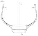
- FIG. 4is a view of the wearable device 100 as viewed from the back of the base 130.
- the description of the wiring and the sensoris omitted.
- the line that bisects the base 130 of the wearable device 100is referred to as "line M".
- the first arm 111 and the second arm 112are formed in a line-symmetrical shape with respect to the base 130. That is, the first arm 111 and the second arm 112 are formed so as to have the same length in the stretching direction. Therefore, the subject A can wear the wearable device 100 in a well-balanced manner.
- FIG. 5is a block diagram of the detection system 1000 including the wearable device 100 of the present embodiment.
- the detection system 1000 of the present embodimentincludes a wearable device 100, a control device 500, and a display device 600.
- the "display device 600" of the present embodimentcorresponds to the "output device” of the present disclosure.
- the signal processing device 120mainly includes a CPU (Central Processing Unit) 1201, a transmission unit 1202, a storage device 1203, and an interface unit 1204. The components are interconnected by a data bus.
- CPUCentral Processing Unit
- the componentsare interconnected by a data bus.
- the control device 500mainly includes a CPU 501 and a storage device 502.
- the storage device 1203 and the storage device 502are composed of a ROM (Read Only Memory), a RAM (Random Access Memory), and the like.
- the base 130has a connection port 1121 and a connection port 1122. Further, a signal processing device 120 is housed inside the base 130.
- a signal processing device 120is housed inside the base 130.
- one endone end 141A to one end 146A to which the sensor (first sensor 101 to sixth sensor 106) is connected. The opposite end is called the "other end”.
- the other end 141B of the first wiring 141, the other end 142B of the second wiring 142, and the other end 143B of the third wiring 143are detachably connected to the connection port 1121. Further, the other end 144B of the fourth wiring 144, the other end 145B of the fifth wiring 145, and the other end 146B of the sixth wiring 146 are detachably connected to the connection port 1122.
- the other end 141B to the other end 146B and the connection ports 1121,1122are composed of, for example, a jack or a connector.
- the first wiring 141, the second wiring 142, the third wiring 143, the fourth wiring 144, the fifth wiring 145, and the sixth wiring 146are removable from the signal processing device 120.
- the first wiring 141, the second wiring 142, the third wiring 143, the fourth wiring 144, the fifth wiring 145, and the sixth wiring 146are not detachable from the signal processing device 120, and the first wiring 141.
- the second wiring 142, the third wiring 143, the fourth wiring 144, the fifth wiring 145, and the sixth wiring 146may be integrally molded with the signal processing device 120.
- the first sensor 101, the second sensor 102, the fourth sensor 104, and the fifth sensor 105are attached to the face of the subject A (see FIG. 3), and detect the myoelectric potential corresponding to the attached portion.
- the first sensor 101, the second sensor 102, the fourth sensor 104, and the fifth sensor 105output a detection signal indicating the detected myoelectric potential to the signal processing device 120.
- the third sensor 103 and the sixth sensor 106detect the reference potential which is the reference of the myoelectric potential.
- the third sensor 103 and the sixth sensor 106are attached at locations where the reference potential can be detected.
- the location where the reference potential can be detectedis, for example, behind the ear of subject A.
- the third sensor 103is attached behind the left ear of subject A (see FIG. 2)
- the sixth sensor 106is attached behind the right ear of subject A.
- the potential detected by the third sensor 103 and the sixth sensor 106is taken as a reference potential.
- the third sensor 103 and the sixth sensor 106output a detection signal indicating the detected reference potential to the signal processing device 120.
- the CPU 1201uses the myoelectric potential indicated by the detection signals from each of the first sensor 101, the second sensor 102, the fourth sensor 104, and the fifth sensor 105 as the reference potential detected by the third sensor 103 and the sixth sensor 106. Is converted into a potential based on.
- the CPU 1201calculates, for example, the difference between the myoelectric potential detected by the first sensor 101 and the second sensor 102 and the potential (reference potential) detected by the third sensor 103. Further, the CPU 1201 calculates, for example, the difference between the myoelectric potential detected by the 4th sensor 104 and the 5th sensor 105 and the potential (reference potential) detected by the 6th sensor 106. In this way, the CPU 1201 calculates four differential potentials.
- the CPU 1201executes a process of changing the information indicating the converted myoelectric potential into a format that can be received by the control device 500.
- the CPU 1201wirelessly transmits the changed signal (control signal) to the control device 500 via the transmission unit 1202.
- This control signalincludes the above-mentioned four differential potentials.
- the control device 500receives the control signal from the wearable device 100
- the CPU 501executes a predetermined process based on the control signal.
- the predetermined processis, for example, a process of estimating the emotion of the subject A.
- the CPU 501 of the control device 500extracts four differential potentials from the control signal transmitted from the wearable device 100. Further, a table in which the four potentials and emotions are associated with each other is generated in advance and stored in the storage device 502. The CPU 502 refers to this table to extract emotions corresponding to the four myoelectric potentials indicated by the control signals.
- the control device 500outputs the extracted emotion as an estimation result.
- the CPU 501may estimate emotions by inputting the myoelectric potentials of the four parts of the subject A and the two reference potentials to the neural network stored in the storage device 502. ..
- the control device 500outputs information indicating an estimation result (estimated emotion) to the display device 600.
- the "estimation result" of the present embodimentcorresponds to the "control information" of the present disclosure.
- the display device 600displays information indicating an estimation result (estimated emotion).
- the control device 500may output the estimation result to a printer and have the printer print the estimation result on paper and output the estimation result. Thereby, the analyst
- the wearable device 100 and the control device 500are connected by wire, and the wearable device 100 transmits a control signal to the control device 500 by this wiring.
- the wiring connecting the wearable device 100 and the control device 500may interfere with other objects. Therefore, in the present embodiment, the wearable device 100 wirelessly transmits a control signal to the control device 500. As a result, it is possible to reduce the occurrence of events such as the wiring interfering with other objects.
- the interface unit 1204accepts the connection to the wearable device 100 of the external storage device 1205. That is, the wearable device 100 can be equipped with the external storage device 1205.
- the external storage device 1205is, for example, a USB (Universal Serial Bus) memory.
- the CPU 1201executes a process of changing the detection signal from the first sensor 101 to the sixth sensor 106 into a format that can be stored by the external storage device 1205. This process produces detection information.
- the CPU 1201stores the detection information (for example, the estimated emotion of the subject A) in the external storage device 1205.
- the analystcan connect the external storage device 1205 to another device (for example, a PC (personal computer)) and recognize the emotion of the subject A with the other device.
- another devicefor example, a PC (personal computer)
- the system of the above-mentioned non-patent documentincludes a stationary processing device, a plurality of sensors, and wiring connecting the processing device and each of the plurality of sensors.
- long wiringis required in order to increase the degree of freedom of the subject's position when detecting the subject's physical data.
- the wiringmay be entangled or the wiring may interfere with other objects, so that there is a problem that it is complicated to attach the sensor to the subject's face.
- the wearable device 100 of the present disclosurecan be attached to the head and neck of the subject A, the wearable device 100 and the control device 500 are independent of each other.
- the wearable device 100includes a sensor attached to the body of the subject (first sensor 101 to sixth sensor 106) and wiring connected to the sensor (first wiring 141 to sixth wiring 146). Therefore, in the wearable device 100 of the present disclosure, the length of the wiring can be shortened as compared with the above-mentioned system. As a result, it is possible to reduce the possibility that the wiring is entangled in the head and neck of the subject when the sensor is attached and that the wiring interferes with other objects.
- the wearable device 100 of the present disclosureit is possible to improve the attachability of the sensor to the head and neck of the subject. Further, even when the subject performs some operation with a plurality of sensors attached, it is possible to reduce the entanglement of the wiring or the interference between the wiring and other objects.
- the wearable device 100in the wearable device 100, the wiring arranged along the first arm 111 (for example, the first wiring 141 to the third wiring 143) and the sensor connected to the wiring (for example, for example).
- the first sensor 101 to the third sensor 103)are provided.
- the wearable device 100includes a wiring arranged along the second arm 112 (for example, the fourth wiring 144 to the sixth wiring 146) and a sensor connected to the wiring (for example, the fourth sensor 104 to the sixth). It is equipped with a sensor 106). Therefore, the subject A wearing the wearable device 100 can attach sensors protruding from both sides of the subject A's face to the subject A's face. Therefore, it is possible to improve the convenience when attaching the sensor to the face of the subject A.
- the first arm 111 and the second arm 112have a shape symmetrical with respect to the base 130 (line M). Therefore, the subject A can wear the wearable device 100 in a well-balanced manner.
- the tip of the first arm 111is formed with a left ear hook portion 121 that is shaped to be hung on the left ear of the subject A.
- the tip of the second arm 112is formed with a right ear hook portion 122 that is shaped to be hung on the right ear of the subject A.
- the base 130is located at the head and neck (occipital region AB) of the subject. As a result, the subject A can stably wear the wearable device 100.
- all of the first wiring 141 to the sixth wiring 146are removable from the signal processing device 120. Therefore, for example, unnecessary sensors and wiring can be removed from the wearable device 100, and as a result, the convenience of detecting the body data of the subject A can be improved.
- the wearable device 100the myoelectric potential of the subject A is detected by the first sensor 101, the second sensor 102, the fourth sensor 104, and the fifth sensor 105.
- the third sensor 103 and the sixth sensor 106detect the reference potential of the myoelectric potential. Therefore, the wearable device 100 can calculate the potential (the above-mentioned difference potential) with reference to the reference potential.
- FIG. 6is an enlarged view of the left ear hook portion 121 of the first arm 111.
- the first arm 111is formed with a first groove portion 1161, a second groove portion 1162, a third groove portion 1163, a fourth groove portion 1164, and a fifth groove portion 1165.
- the first groove portion 1161, the second groove portion 1162, the third groove portion 1163, and the fifth groove portion 1165have a shape along the extending direction of the first arm 111.
- the first arm 111includes a stretched portion 111A that extends linearly or substantially linearly.
- the first groove portion 1161is formed from a portion connected to the base portion 130 of the first arm 111 to the edge portion 111B of the extension portion 111A.
- the second groove portion 1162is formed along the extending direction of the left ear hook portion 121.
- the first groove portion 1161 and the second groove portion 1162have a relationship in which one groove portion is divided.
- the third groove portion 1163is formed over the extension portion 111A and the left ear hook portion 121.
- the fourth groove portion 1164is formed at the tip of the left ear hook portion 121.
- the third groove portion 1163 and the fourth groove portion 1164have a relationship in which one groove portion is divided.
- the fifth groove portion 1165is formed from a portion connected to the base portion 130 of the first arm 111 to the edge portion 111C of the extension portion 111A.
- FIG. 7is an enlarged view of the left ear hook portion 121 with the wiring arranged in the groove portion.
- the first wiring 141is arranged in the first groove portion 1161 and the second groove portion 1162.
- the first wiring 141is arranged in the first groove portion 1161.
- a portion of the first wiring 141 different from the portion arranged in the first groove portion 1161is arranged in the second groove portion 1162 in the extending direction of the first wiring.
- the slack 141S of the first wiring 141is formed between the first groove portion 1161 and the second groove portion 1162.
- the positional relationship between the first groove portion 1161 and the second groove portion 1162is such that the first groove portion 1161 and the second groove portion 1162 are in a state where the first wiring 141 is arranged in the first groove portion 1161 and the second groove portion 1162.
- the slack 141S of the first wiring 141can be formed between them.
- the first wiring 141is arranged in a plurality of groove portions (in the example of FIG. 7, the first groove portion 1161 and the second groove portion 1162).
- the first sensor 101is connected to one end of the protruding portion 141T protruding from the first arm 111.
- the second wiring 142is arranged in the third groove portion 1163 and the fourth groove portion 1164.
- a slack 142S of the second wiring 142is formed between the third groove portion 1163 and the fourth groove portion 1164.
- the positional relationship between the third groove portion 1163 and the fourth groove portion 1164is such that the second groove portion 1162 and the fourth groove portion 1164 have the second wiring 142 arranged in the third groove portion 1163 and the fourth groove portion 1164.
- the slack 142S of the second wiring 142can be formed between them.
- the second wiring 142is arranged in a plurality of groove portions (in the example of FIG. 7, the third groove portion 1163 and the fourth groove portion 1164).
- the second sensor 102is connected to one end of the protruding portion 142T protruding from the first arm 111.
- the third wiring 143is arranged in the fifth groove portion 1165.
- the third wiring 143is not arranged in a plurality of grooves like the first wiring 141 and the second wiring 142, but is arranged in one fifth groove portion 1165. Therefore, the slack of the third wiring 143 is not formed.
- the first wiring 141 to the third wiring 143are arranged along the first arm 111 by being arranged in the groove portion. Therefore, the first wiring 141 to the third wiring 143 can be arranged along the first arm 111 with a relatively simple configuration.
- FIG. 8is a diagram schematically showing a first groove portion 1161, a second groove portion 1162, a fifth groove portion 1175, and the like of the first arm 111.
- the first wiring 141is arranged in the first groove portion 1171 and the second groove portion 1172, and the slack 141S is formed.
- the third wiring 143is arranged in the fifth groove portion 1175.
- the length of the protruding portion 141T protruding from the first arm 111is referred to as "length L1”.
- the length of the protruding portion 143T protruding from the first arm 111is referred to as "length L3".
- the first wiring 141is composed of a conductor to be stretched and a sheath that covers the conductor and stretches in the stretching direction of the conductor.
- the sheathis composed of a rigid and elastic insulator. Therefore, the first wiring 141 has rigidity and elasticity.
- the sheathis mainly made of chloroprene rubber, polyvinyl chloride, polyethylene or the like.
- the other end 141B of the first wiring 141is connected (fixed) to the signal processing device 120. Therefore, when the slack 141S of the first wiring 141 is pushed in the direction of the arrow ⁇ 1 by the subject A or the like, the first wiring 141 has rigidity and the other end 141B of the first wiring 141 is fixed. The protruding portion 141T of the first wiring 141 is pushed out in the direction of the arrow ⁇ 1. That is, the length L1 of the protruding portion 141T of the first wiring 141 becomes long.
- the slack 141Smoves in the direction of the arrow ⁇ 1 and the length of the protruding portion 141T of the first wiring 141 L1 becomes longer.
- the protruding portion 141T of the first wiring 141is pulled in the direction of the arrow ⁇ 2. That is, the length L1 of the protruding portion 141T of the first wiring 141 is shortened. Further, even when the protruding portion 141T of the first wiring 141 is pushed in the direction of the arrow ⁇ 2 by the subject A or the like, the slack 141S moves in the direction of the arrow ⁇ 2 and the length of the protruding portion 141T of the first wiring 141. L1 becomes shorter.
- the first adjusting portion 1181capable of adjusting the length of the protruding portion 141T of the first wiring 141 is formed on the first arm 111. Further, as shown in FIG. 6, the first adjusting portion 1181 is composed of a first groove portion 1171 and a second groove portion 1172. Further, the length L1 of the protruding portion 141T can be adjusted by adjusting the slack 141S by the subject A or the like.
- the wearable device 100has a first adjusting portion 1181 capable of adjusting the length L1 of the protruding portion 141T. Therefore, in the wearable device 100, by having the first adjusting unit 1181, it is possible to reduce the occurrence of such a problem and improve the convenience of the user.
- the first adjusting portion 1181is composed of a first groove portion 1171 and a second groove portion 1172. Therefore, the first adjusting unit 1181 can be formed with a relatively simple configuration.
- an adjusting portion capable of adjusting the protruding portion 142T of the second wiring 142is also formed with the same configuration as that of the first adjusting portion 1181. Specifically, the protruding portion 142T of the second wiring 142 is adjustable based on the slack 142S formed for the second wiring 142.
- the third wiring 143will be described with reference to FIG. As described above, the slack of the third wiring 143 is not formed.
- the third sensor 103 connected to one end 143A of the third wiring 143detects the reference potential.
- the place where the reference potential can be detected on the face of the subjectis generally fixed. Therefore, since it is less necessary to change the location where the reference potential is detected according to the subject, there is no particular problem even if the length of the protruding portion 143T of the third wiring 143 is fixed. Therefore, in the present embodiment, the adjusting portion for adjusting the length of the protruding portion 143T of the third wiring 143 is not formed.
- the groove portion in which the third wiring 143 is arrangedis one fifth groove portion 1175. As a result, it is possible to prevent the formation of an unnecessary adjustment portion (unnecessary groove portion). Even if the adjusting portion for the third wiring 143 is not provided, the protruding portion of the third wiring 143 from the first arm 111 may be adjusted by the extra length of the third wiring 143.
- FIG. 9is an enlarged view of the right ear hook portion 122 of the second arm 112.
- the second arm 112is formed with a first groove portion 1171, a second groove portion 1172, a third groove portion 1173, a fourth groove portion 1174, and a fifth groove portion 1175.
- the first arm 111 and the second arm 112have shapes that are axisymmetric with respect to the base 130 (line M). Therefore, the first groove portion 1171 is formed to face the first groove portion 1161, the second groove portion 1172 is formed to face the second groove portion 1162, and the third groove portion 1173 faces the third groove portion 1163.
- the fourth groove portion 1174is formed so as to face the fourth groove portion 1164, and the fifth groove portion 1175 is formed so as to face the fifth groove portion 1165.
- the fourth wiring 144is arranged in the first groove portion 1171 and the second groove portion 1172. Further, a slack in the fourth wiring 144 is formed between the first groove portion 1171 and the second groove portion 1172.
- the fifth wiring 145is arranged in the third groove portion 1173 and the fourth groove portion 1174. Further, a slack in the fifth wiring 145 is formed between the third groove portion 1173 and the fourth groove portion 1174.
- the sixth wiring 146is arranged in the fifth groove portion 1175. Further, the slack of the sixth wiring 146 is not formed.
- the adjusting portionthat can adjust the length of the portion of the fourth wiring 144 that protrudes from the second arm 112, and the portion of the fifth wiring 145 that protrudes from the second arm 112.
- An adjustment portion whose length can be adjustedis formed.
- the second adjusting portion 1182is composed of a first groove portion 1171 and a second groove portion 1172. Further, the length of the portion of the fourth wiring 144 protruding from the second arm 112 can be adjusted based on the slack of the fourth wiring 144 formed between the first groove portion 1171 and the second groove portion 1172. ..
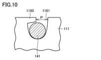
- FIG. 10is a diagram showing an example of a cross section of the first groove portion 1161 and the first wiring 141 arranged in the first groove portion 1161.
- the claw portion 1180is formed on the edge of the opening portion of the first groove portion 1161.
- the first wiring 141can be fastened to the first groove portion 1161. As a result, it is possible to reduce the disconnection of the first wiring 141 from the first groove portion 1161.
- the first wiring 141has elasticity.
- the userpushes the first wiring 141 from the gap P between the claw portion 1180 and the first groove portion 1161 to make the first wiring.
- 141can be arranged in the first groove 1161. Further, in a state where the first wiring 141 is arranged in the first groove portion 1161, the user pulls the first wiring 141 to disengage the first wiring 141 from the gap P, and the first wiring 141 first groove portion 1161 Can be removed from.
- One or more claw portions 1180are formed at predetermined positions of the first groove portion 1161. Further, one or more claw portions 1180 are formed in each of the second groove portion 1162 to the fifth groove portion 1165 and the first groove portion 1171 to the fifth groove portion 1175.
- FIG. 10an example in which the claw portions are provided on one side of the left and right sides has been described, but the present invention is not limited to this, and the claws may be arranged alternately on the left and right sides, or the claws may protrude from the left and right at the same location. good.
- FIG. 11is a diagram showing a configuration example of the detection system 1000A according to the second embodiment.
- the second sensor 102is replaced by the sweat sensor 182 that detects the sweating of the subject.
- the sweat sensor 182is a sensor capable of detecting a component (for example, lactic acid) contained in human sweat.
- the fourth sensor 104is replaced by the temperature sensor 185 that detects the body temperature of the subject.
- the temperature sensor 185is composed of, for example, a thermistor.
- the wearable device 100A and the detection system 1000A of the second embodimentcan detect various physical data of the subject A. Further, since the sensor and the wiring are detachable from the wearable device 100, a sensor capable of detecting the body data desired by the user can be attached to the wearable device 100.
- the wearable device of the example of FIG. 11includes a first sensor 101 and a fourth sensor 104 for detecting a myoelectric potential, and a third sensor 103 and a sixth sensor 106 for detecting a reference potential, but has six sensors. Each of them may detect different body data.
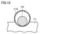
- FIG. 12is a diagram showing an example of a cross section of the tube portion 1170, which is the holding portion of the third embodiment. As shown in FIG. 12, the tube portion 1170 is formed on the surface of the first arm 111 along the extending direction of the first wiring 141. Further, the first wiring 141 is arranged so as to penetrate inside the tube portion 1170. As in the third embodiment, even if the holding portion for holding the wiring is the tube portion 1170, the first arm 111 can appropriately hold the first wiring 141.
- first tube portion and the second tube portionmay be provided so as to form the slack of the first wiring 141.
- a tube portion for holding at least one of the second wiring 142 to the sixth wiring 146may be formed.
- one wiringmay be held by combining the groove portion and the tube portion.
- the holding portion for holding the wiringmay have a configuration different from that of the groove portion and the tube portion.
- the holding portion and the wiringmay be magnets that attract each other, and the wiring may be held by the arm by magnetic force.
- the arminstead of holding the wiring inside the pipe portion, the arm itself may have a hollow structure and the cable may be passed through the structure.
- the wearable device 100may have another shape as long as it can be worn on the body of the subject A.
- itmay be shaped so as to be hung on the neck of the subject A.
- the adjusting portion capable of preventing rust from the length of the protruding portion 141T of the first wiring 141is composed of a plurality of grooves.
- the adjusting unitmay have another configuration.
- the adjusting unitmay have, for example, a winding structure for winding the first wiring 141.
- a wearable devicethat can be worn on the head and neck of a subject, and is a base, a first arm extending from the base, a second arm extending from the base, and a first arm arranged along the first arm.
- One wiring and one end of the first wiringare connected, and the first sensor attached to the subject while the subject is wearing a wearable device to detect the physical data of the subject is connected to the other end of the first wiring.
- a signal processing device for processing a detection signal from the first sensor, the signal processing deviceis a wearable device attached to a base.
- the wearable devicethat can be worn on the head and neck of the subject, and the wearable device includes a sensor attached to the body of the subject and wiring connected to the sensor. Therefore, the length of the wiring can be shortened, and as a result, the wiring can be reduced from being entangled or interfering with other objects. Therefore, it is possible to provide a wearable device having improved attachability of the sensor to the head and neck of the subject.
- the length of the portion protruding from the first armcan be adjusted, so that the convenience can be improved.
- the second wiring arranged along the second arm and one end of the second wiringare connected, and the subject wears the wearable device. It is further provided with a second sensor attached to the subject's body in the state of being present and detecting the subject's body data, and the other end of the second wiring is connected to the signal processing device.
- the first sensor and the second sensorcan be easily attached to the body of the subject.
- the length of the portion protruding from the second armcan be adjusted, so that the convenience can be improved.
- the first adjusting portionis held by the first holding portion that holds the first wiring in the extending direction of the first wiring and the first holding portion. It has a second holding portion that holds the first wiring in a portion different from the portion in the extending direction of the first wiring, and the length of the portion of the first wiring protruding from the first arm is the first. It can be adjusted based on the slack of the first wiring formed between the holding portion and the second holding portion.
- the first adjusting portioncan be formed with a relatively simple configuration.
- the wearable device according to the item 5at least one of the first holding portion and the second holding portion is a groove portion in which the first wiring is arranged.
- the first adjusting portioncan be formed by the groove portion that can be formed relatively easily.
- the groove portionhas a claw portion for fastening the arranged first wiring.
- At least one of the first holding portion and the second holding portionis a tube portion through which the first wiring can penetrate inside.
- the first adjusting portioncan be formed by the pipe portion that can be formed relatively easily.
- the second adjusting unitis held by a third holding unit that holds the second wiring in the extending direction of the second wiring and a third holding unit. It has a fourth holding portion that holds the second wiring in the extending direction of the second wiring, and the length of the portion of the second wiring protruding from the second arm is the third holding portion and the fourth holding portion. It can be adjusted based on the slack of the second wiring formed between the portions.
- the second adjusting portioncan be formed with a relatively simple configuration.
- the first sensordetects the myoelectric potential of the subject, and the wearable device is further arranged along the first arm.
- a third sensorthat is connected to one end of the third wiring and is attached to the subject's body to detect the reference potential while the subject is wearing a wearable device, and the other end of the third wiring is It is connected to a signal processing device.
- the first arm and the second armhave a shape that is axisymmetric with respect to the base.
- subject Acan wear a wearable device in a well-balanced manner.
- the tip of the first armis hung on the subject's left ear while the subject is wearing the wearable device. It has a shape, the tip of the second arm has a shape to be hung on the subject's right ear, and the base is located on the subject's head.
- the physical data of the head of the subjectcan be detected.
- the first wiringis removable from the signal processing device.
- the first wiringwhen the first wiring is unnecessary, the first wiring can be removed.
- the signal processing deviceIn the wearable device according to any one of paragraphs 1 to 15, the signal processing device generates detection information by processing the detection signal, and the wearable device is an external storage device. Can be installed and outputs detection information to an external storage device.
- the detection information generated by the signal processing devicecan be stored in the external storage device.
- the signal processing devicewirelessly transmits the control device.
- the signal processing devicetransmits a control signal to the control device by wired communication
- the wired wiringinterferes with other objects.
- the signal processing devicesince the signal processing device wirelessly transmits the control signal, it is possible to reduce the occurrence of such a problem.
- 100 wearable device101 1st sensor, 102 2nd sensor, 103 3rd sensor, 104 4th sensor, 105 5th sensor, 106 6th sensor, 111 1st arm, 111A extension part, 111B, 111C edge part, 112 2nd arm, 120 signal processing device, 121 left ear hook, 122 right ear hook, 130 base, 141 1st wiring, 141S, 142S slack, 141T, 142T, 143T protruding part, 142 2nd wiring, 143 3rd Wiring, 144 4th wiring, 145 5th wiring, 146 6th wiring, 151 1st electrode pad, 152 2nd electrode pad, 153 3rd electrode pad, 154 4th electrode pad, 155 5th electrode pad, 156th 6th Electrode pad, 182 sweat sensor, 185 temperature sensor, 500 control device, 502,1203 storage device, 600 display device, 1000,1000A detection system, 1121,1122 connection port, 1161,1171 first groove,
Landscapes
- Health & Medical Sciences (AREA)
- Life Sciences & Earth Sciences (AREA)
- Engineering & Computer Science (AREA)
- General Health & Medical Sciences (AREA)
- Veterinary Medicine (AREA)
- Biophysics (AREA)
- Biomedical Technology (AREA)
- Heart & Thoracic Surgery (AREA)
- Medical Informatics (AREA)
- Molecular Biology (AREA)
- Surgery (AREA)
- Animal Behavior & Ethology (AREA)
- Physics & Mathematics (AREA)
- Public Health (AREA)
- Pathology (AREA)
- Psychiatry (AREA)
- Psychology (AREA)
- Child & Adolescent Psychology (AREA)
- Developmental Disabilities (AREA)
- Educational Technology (AREA)
- Hospice & Palliative Care (AREA)
- Social Psychology (AREA)
- Ophthalmology & Optometry (AREA)
- Measurement And Recording Of Electrical Phenomena And Electrical Characteristics Of The Living Body (AREA)
Abstract
Description
Translated fromJapanese本発明は、ウェアラブルデバイス、および検出システムに関する。The present invention relates to a wearable device and a detection system.
非特許文献1では、被験者の顔の筋電位を検出して、この筋電位に基づいて、被験者の感情を推定するシステムが開示されている。このシステムは、据え置きの処理装置と、複数のセンサと、該処理装置と該複数のセンサとを接続する配線とを備える。Non-Patent
このシステムでは、複数のセンサをパッドなどにより被験者の顔に取付けて、被験者の顔の筋電位を該センサにより検出する。センサは、該センサが検出した筋電位を示す筋電位信号を配線経由で処理装置に出力する。処理装置は、該筋電位信号に基づいて、被験者の感情を推定する。In this system, a plurality of sensors are attached to the subject's face with a pad or the like, and the myoelectric potential of the subject's face is detected by the sensor. The sensor outputs a myoelectric potential signal indicating the myoelectric potential detected by the sensor to the processing device via wiring. The processing device estimates the emotion of the subject based on the myoelectric potential signal.
上述のシステムでは、被験者にセンサが取付けられた状態での被験者の位置の自由度を高めるために、長い配線が必要とされる。しかしながら、配線が長いことから、被験者の身体にセンサが取付けられる際に、配線がもつれたり、配線が他の物と干渉したりする。したがって、上述のシステムでは、被験者の身体に、センサを取付ける作業が煩雑であるという問題がある。In the above system, long wiring is required in order to increase the degree of freedom of the subject's position when the sensor is attached to the subject. However, due to the long wiring, when the sensor is attached to the subject's body, the wiring may become entangled or the wiring may interfere with other objects. Therefore, in the above-mentioned system, there is a problem that the work of attaching the sensor to the body of the subject is complicated.
本発明の目的は、センサの被験者の頭頸部への取付け性が向上したウェアラブルデバイスを提供することである。An object of the present invention is to provide a wearable device having improved attachability of a sensor to the head and neck of a subject.
本開示のある局面に従うウェアラブルデバイスは、被験者の頭頸部に装着可能である。ウェアラブルデバイスは、基部と、第1アームと、第2アームと、第1配線と、第1センサと、信号処理装置とを備える。第1アームは基部から延伸する。第2アームは基部から延伸する。第1配線は、第1アームに沿って配置される。第1センサは、第1配線の一端に接続され、被験者がウェアラブルデバイスを装着している状態で被験者に取付けられて被験者の身体データを検出する。信号処理装置は、第1配線の他端が接続され、第1センサからの検出信号を処理する。信号処理装置は、基部に取付けられる。A wearable device according to certain aspects of this disclosure can be worn on the head and neck of the subject. The wearable device includes a base, a first arm, a second arm, a first wiring, a first sensor, and a signal processing device. The first arm extends from the base. The second arm extends from the base. The first wiring is arranged along the first arm. The first sensor is connected to one end of the first wiring and is attached to the subject while the subject is wearing a wearable device to detect the body data of the subject. The signal processing device is connected to the other end of the first wiring and processes the detection signal from the first sensor. The signal processing device is mounted on the base.
本開示によれば、配線が第1アームに沿って延びる構成とすることで、被験者の頭頸部への取付け性が向上したウェアラブルデバイスを提供することができる。According to the present disclosure, it is possible to provide a wearable device having improved attachability to the head and neck of a subject by configuring the wiring to extend along the first arm.
以下、本開示の実施の形態について、図面を参照しながら詳細に説明する。なお、図中同一または相当部分には同一符号を付してその説明は繰り返さない。Hereinafter, embodiments of the present disclosure will be described in detail with reference to the drawings. The same or corresponding parts in the drawings are designated by the same reference numerals and the description thereof will not be repeated.
<第1の実施の形態>
[ウェアラブルデバイスの構成]
図1は、ウェアラブルデバイス100を示す図である。図1を参照して、ウェアラブルデバイス100は、基部130と、第1アーム111と、第2アーム112とを備える。基部130の両端から、第1アーム111と、第2アーム112とがそれぞれ延伸する。第1アーム111および第2アーム112の各々は、ウェアラブルデバイス100の装着状態において、被験者Aの頭部に沿うように、湾曲して延伸する形状を有する。<First Embodiment>
[Wearable device configuration]
FIG. 1 is a diagram showing a
第1アーム111および第2アーム112の先端は、略半円となるように延伸している。この略半円の弧の部分が被験者Aの耳に掛けられる。第1アーム111の先端には、被験者Aの左耳に掛けられる左耳掛け部121が形成される。第2アーム112の先端には、被験者Aの右耳に掛けられる右耳掛け部122が形成される。The tips of the
ウェアラブルデバイス100は、さらに、第1配線141、第2配線142、第3配線143、第4配線144、第5配線145、および第6配線146を備える。また、ウェアラブルデバイス100は、第1配線141~第6配線146にそれぞれ対応して接続された、第1センサ101、第2センサ102、第3センサ103、第4センサ104、第5センサ105、および第6センサ106を備える。The
第1センサ101は、第1電極パッド151に内蔵されている。第2センサ102は、第2電極パッド152に内蔵されている。第3センサ103は、第3電極パッド153に内蔵されている。第4センサ104は、第4電極パッド154に内蔵されている。第5センサ105は、第5電極パッド155に内蔵されている。第6センサ106は、第6電極パッド156に内蔵されている。The
ウェアラブルデバイス100の装着状態において、第1センサ101、第2センサ102、第3センサ103、第4センサ104、第5センサ105、および第6センサ106は、それぞれ、第1電極パッド151、第2電極パッド152、第3電極パッド153、第4電極パッド154、第5電極パッド155、および第6電極パッド156を介して、被験者の頭部に取付けられる。In the mounted state of the
第1アーム111に沿って、第1配線141、第2配線142、および第3配線143が配置されている。後述するように、第1配線141、第2配線142、および第3配線143は、第1アーム111に形成された溝部に配置されている。第1配線141の一端141Aには、第1センサ101が接続されている。第2配線142の一端142Aには、第2センサ102が接続されている。第3配線143の一端143Aには、第3センサ103が接続されている。The
第2アーム112に沿って、第4配線144、第5配線145、および第6配線146が配置されている。後述するように、第4配線144、第5配線145、および第6配線146は、第2アーム112に形成された溝部に配置されている。第4配線144の一端144Aには、第4センサ104が接続されている。第5配線145の一端145Aには、第5センサ105が接続されている。第6配線146の一端146Aには、第6センサ106が接続されている。なお、溝部は、第1アーム111と第2アーム112とにおいてそれぞれ対向し合う表面に形成される。Along the
以下では、第1センサ101~第6センサ106をまとめて、「センサ群」ともいう。センサ群は、ウェアラブルデバイス100の装着状態において被験者Aの頭部に取付けられて被験者Aの身体データを検出する。身体データは、被験者Aの身体に関するデータであり、たとえば、被験者の顔の筋電位、被験者の発汗量、被験者の体温、被験者の体内の水分量、被験者の脈波、被験者の音、被験者の部位(被験者の口または顎)の加速度、脳波、脳活動および心電位のうち少なくとも1つを含む。被験者の音は、たとえば、被験者の体内の音(たとえば、呼吸音または嚥下音など)を含む。被験者の部位の加速度は、たとえば、被験者の筋肉の加速度などを含む。Hereinafter, the
図2および図3は、第1の実施の形態のウェアラブルデバイス100が被験者Aの頭頸部に装着されるとともに、ウェアラブルデバイス100が有するセンサが該被験者Aに取付けられた状態を示す図である。被験者の頭頸部とは、典型的には、被験者の首より上の部分である。図2は該被験者Aを斜め後ろから見た図であり、図3は被験者Aを正面から見た図である。後述する検出システムは、ウェアラブルデバイス100を装着した被験者Aの感情を推定する。また、被験者Aの他に、被験者Aの感情の推定結果を確認する分析者(特に図示せず)が存在する。以下では、分析者および被験者Aをまとめて「ユーザ」とも称される。2 and 3 are diagrams showing a state in which the
図2の例では、基部130、第1アーム111、第2アーム112、第1センサ101、第2センサ102、および第3センサ103などが示されている。第1アーム111は装着状態において左側のアームであり、第2アーム112は装着状態において右側のアームである。なお、第1アーム111は装着状態において右側のアームであり、第2アーム112は装着状態において左側のアームとしてもよい。In the example of FIG. 2, the
図2の例では、第1アーム111の左耳掛け部121が、被験者Aの左耳ALに掛けられている状態が示されている。なお、図2には示されていないが、第2アーム112の右耳掛け部122(図1参照)が、被験者Aの右耳に掛けられる。In the example of FIG. 2, the state in which the left
ウェアラブルデバイス100が装着された状態において、基部130は、被験者Aの後頭部ABに位置する。また、後述するように、基部130には、信号処理装置120(図5参照)が収容されていることから、所定の重さを有する。左耳掛け部121および右耳掛け部122は、それぞれ、被験者Aの左耳および右耳に掛けられる。また、基部130などの自重により、被験者Aは、ウェアラブルデバイス100を安定して装着することができる。With the
図3は、ウェアラブルデバイス100を装着した被験者Aを正面から見た図である。図3の例では、第1センサ101、第2センサ102、第4センサ104、第5センサ105が被験者Aの顔に取付けられている。これらのセンサは、たとえば、頬骨筋または皺眉筋に取付けられ、頬骨筋の筋電位または皺眉筋の筋電位を検出する。FIG. 3 is a front view of subject A wearing the
図4は、ウェアラブルデバイス100を基部130の背面から見た図である。図4では、配線およびセンサの記載が省略されている。また、ウェアラブルデバイス100の基部130を二等分する線を「線M」と称する。第1アーム111と第2アーム112とは、基部130を基準として線対称の形状に形成されている。すなわち、第1アーム111および第2アーム112は、延伸方向の長さが同一となるように形成されている。したがって、被験者Aは、バランス良く、ウェアラブルデバイス100を装着することができる。FIG. 4 is a view of the
[検出システム]
図5は、本実施の形態のウェアラブルデバイス100を含む検出システム1000のブロック図である。本実施の形態の検出システム1000は、ウェアラブルデバイス100と、制御装置500と、表示装置600とを備える。本実施の形態の「表示装置600」は、本開示の「出力装置」に対応する。[Detection system]
FIG. 5 is a block diagram of the
信号処理装置120は、主に、CPU(Central Processing Unit)1201と、送信部1202と、記憶装置1203と、インターフェース部1204とを有する。各構成要素はデータバスによって相互に接続されている。The
制御装置500は、主に、CPU501と、記憶装置502とを備える。記憶装置1203と、記憶装置502とは、ROM(Read Only Memory)と、RAM(Random Access Memory)などから構成される。The
基部130は、接続ポート1121と、接続ポート1122とを有する。さらに、基部130の内部には、信号処理装置120が収容される。以下では、上述の配線(第1配線141~第6配線146)のうちの両端のうち、センサ(第1センサ101~第6センサ106)が接続されている一端(一端141A~一端146A)の反対側の端を「他端」という。The
第1配線141の他端141B、第2配線142の他端142B、および第3配線143の他端143Bは、着脱可能に接続ポート1121に接続される。また、第4配線144の他端144B、第5配線145の他端145B、および第6配線146の他端146Bは、着脱可能に接続ポート1122に接続される。他端141B~他端146Bと、接続ポート1121,1122とは、たとえば、ジャックまたはコネクタなどにより構成される。The
つまり、第1配線141、第2配線142、第3配線143、第4配線144、第5配線145、および第6配線146は、信号処理装置120に対して着脱可能である。なお、第1配線141、第2配線142、第3配線143、第4配線144、第5配線145、および第6配線146は、信号処理装置120に対して着脱可能ではなく、第1配線141、第2配線142、第3配線143、第4配線144、第5配線145、および第6配線146と、信号処理装置120とは一体成型されてもよい。That is, the
第1センサ101、第2センサ102、第4センサ104、および第5センサ105は、被験者Aの顔に取付けられ(図3参照)、取付けられた箇所に対応する筋電位を検出する。たとえば、第1センサ101、第2センサ102、第4センサ104、および第5センサ105は、検出した筋電位を示す検出信号を、信号処理装置120に出力する。The
一方、第3センサ103、および第6センサ106は、筋電位の基準となる基準電位を検出する。第3センサ103、および第6センサ106は、基準電位を検出可能な箇所に取付けられる。基準電位を検出可能な箇所は、たとえば、被験者Aの耳の後ろである。たとえば、第3センサ103は、被験者Aの左耳の後ろに取付けられ(図2参照)、第6センサ106は、被験者Aの右耳の後ろに取付けられる。第3センサ103、および第6センサ106が検出する電位が基準電位とされる。第3センサ103、および第6センサ106は、検出した基準電位を示す検出信号を信号処理装置120に出力する。On the other hand, the
CPU1201は、第1センサ101、第2センサ102、第4センサ104、および第5センサ105のそれぞれからの検出信号が示す筋電位を、第3センサ103および第6センサ106で検出された基準電位を基準とした電位に変換する。CPU1201は、たとえば、第1センサ101、および第2センサ102が検出した筋電位と、第3センサ103が検出した電位(基準電位)との差分を算出する。また、CPU1201は、たとえば、第4センサ104、および第5センサ105が検出した筋電位と、第6センサ106が検出した電位(基準電位)との差分を算出する。このように、CPU1201は、4つの差分電位を算出する。The
さらに、CPU1201は、変換された筋電位を示す情報を、制御装置500が受信可能な形式に変更する処理を実行する。CPU1201は、変更後の信号(制御信号)を、送信部1202経由で制御装置500に無線で送信する。この制御信号には、上述の4つの差分電位が含まれている。制御装置500は、ウェアラブルデバイス100からの制御信号を受信すると、CPU501において該制御信号に基づいて、所定処理を実行する。所定処理は、たとえば、被験者Aの感情を推定する処理である。Further, the
制御装置500のCPU501は、ウェアラブルデバイス100から送信された制御信号から、4つの差分電位を抽出する。また、4つの電位と、感情とが対応づけられたテーブルが予め生成されて、記憶装置502に記憶されている。CPU502は、このテーブルを参照して、制御信号により示される4つの筋電位に対応する感情を抽出する。制御装置500は、この抽出した感情を推定結果として出力する。なお、CPU501は、記憶装置502に記憶されたニューラルネットワークに対して、被験者Aの4つの部位のそれぞれの筋電位と、2つの基準電位とを入力することにより感情を推定するようにしてもよい。制御装置500は、推定結果(推定した感情)を示す情報を表示装置600に出力する。本実施の形態の「推定結果」は、本開示の「制御情報」に対応する。表示装置600は、推定結果(推定された感情)を示す情報を表示する。なお、制御装置500は、プリンタに推定結果を出力し、該プリンタに該推定結果を用紙に印刷させ出力するようにしてもよい。これにより、分析者は、被験者Aの感情を認識することができる。The
また、ウェアラブルデバイス100と制御装置500とを有線接続し、ウェアラブルデバイス100が制御信号をこの配線により制御装置500に送信する構成が考えられる。しかしながら、この構成では、ウェアラブルデバイス100と制御装置500とを結ぶ配線が、他の物と干渉する場合などがある。そこで、本実施の形態では、ウェアラブルデバイス100は、制御装置500に対して、無線で制御信号を送信する。これにより、配線が、他の物と干渉するといった事象の発生を低減できる。Further, it is conceivable that the
また、インターフェース部1204は、外部記憶装置1205のウェアラブルデバイス100に対する接続を受付ける。つまり、ウェアラブルデバイス100は、外部記憶装置1205を装着可能である。外部記憶装置1205は、たとえば、USB(Universal Serial Bus)メモリである。CPU1201は、第1センサ101~第6センサ106からの検出信号に対して、該検出信号を外部記憶装置1205が記憶可能な形式に変更する処理を実行する。この処理により、検出情報が生成される。CPU1201は、検出情報(たとえば、推定された被験者Aの感情)を、外部記憶装置1205に記憶させる。これにより、分析者は、他の装置(たとえば、PC(personal computer))に、外部記憶装置1205を接続させて、この他の装置で、被験者Aの感情を認識することができる。Further, the
上述の非特許文献のシステムでは、据え置きの処理装置と、複数のセンサと、該処理装置と該複数のセンサのそれぞれと接続する配線とを備える。このシステムでは、被験者の身体データを検出する際の該被験者の位置の自由度を高めるために、長い配線が必要とされる。しかしながら、配線が長い場合には、配線がもつれたり、配線が他の物と干渉したりすることから、被験者の顔に、センサを取付けるのが煩雑であるという問題がある。また、上述の非特許文献のシステムでは、複数のセンサが被験者に取付けられている状態で被験者が何らかの動作を行う場合にも配線がもつれたり、配線が他の物と干渉したりするという問題が生じる。The system of the above-mentioned non-patent document includes a stationary processing device, a plurality of sensors, and wiring connecting the processing device and each of the plurality of sensors. In this system, long wiring is required in order to increase the degree of freedom of the subject's position when detecting the subject's physical data. However, when the wiring is long, the wiring may be entangled or the wiring may interfere with other objects, so that there is a problem that it is complicated to attach the sensor to the subject's face. Further, in the system of the above-mentioned non-patent document, there is a problem that the wiring is entangled or the wiring interferes with other objects even when the subject performs some operation while a plurality of sensors are attached to the subject. Occurs.
これに対し、本開示のウェアラブルデバイス100は、被験者Aの頭頸部に装着可能であることから、該ウェアラブルデバイス100と、制御装置500とはそれぞれ独立している。ウェアラブルデバイス100は、被験者の身体に取付けられるセンサ(第1センサ101~第6センサ106)と、該センサに接続されている配線(第1配線141~第6配線146)とを備える。したがって、本開示のウェアラブルデバイス100においては、上述のシステムと比較して、配線の長さを短くすることができる。その結果、被験者の頭頸部に、センサを取付ける際に配線がもつれたり、配線が他の物と干渉したりすることを低減できる。よって、本開示のウェアラブルデバイス100によれば、センサの被験者の頭頸部への取付け性を向上させることができる。また、複数のセンサが取付けられている状態で被験者が何らかの動作を行う場合であっても、配線のもつれ、あるいは、配線と他の物との干渉を低減できる。On the other hand, since the
また、図1に示すように、ウェアラブルデバイス100では、第1アーム111に沿って配置される配線(たとえば、第1配線141~第3配線143)と、該配線に接続されるセンサ(たとえば、第1センサ101~第3センサ103)とを備える。これとともにウェアラブルデバイス100は、第2アーム112に沿って配置される配線(たとえば、第4配線144~第6配線146)と、該配線に接続されるセンサ(たとえば、第4センサ104~第6センサ106)とを備える。したがって、ウェアラブルデバイス100を装着している被験者Aは、被験者Aの顔の両側から突出しているセンサを、被験者Aの顔に取付けることができる。したがって、センサを被験者Aの顔に取付ける際の利便性を向上させることができる。Further, as shown in FIG. 1, in the
また、図4に示すように、第1アーム111と第2アーム112とは、基部130(線M)を基準として線対称な形状である。したがって、被験者Aは、バランス良く、ウェアラブルデバイス100を装着できる。Further, as shown in FIG. 4, the
また、図1に示すように、第1アーム111の先端は、被験者Aの左耳に掛けられる形状である左耳掛け部121が形成されている。また、第2アーム112の先端は、被験者Aの右耳に掛けられる形状である右耳掛け部122が形成されている。さらに、図2に示すように、被験者Aがウェアラブルデバイス100を装着している状態では、基部130は、被験者の頭頸部(後頭部AB)に位置する。これにより、被験者Aは、安定して、ウェアラブルデバイス100を装着することができる。Further, as shown in FIG. 1, the tip of the
また、図5に示すように、第1配線141~第6配線146はいずれも信号処理装置120から着脱可能である。したがって、たとえば、不要なセンサおよび配線をウェアラブルデバイス100から外すことができ、その結果、被験者Aの身体データの検出の利便性を向上させることができる。Further, as shown in FIG. 5, all of the
また、ウェアラブルデバイス100において、第1センサ101、第2センサ102、第4センサ104、および第5センサ105により被験者Aの筋電位を検出する。これとともに、第3センサ103および第6センサ106は、該筋電位の基準電位を検出する。したがって、ウェアラブルデバイス100は、基準電位を基準とした電位(上述の差分電位)を算出することができる。Further, in the
[溝部について]
次に、第1アーム111の表面に形成されている溝部を説明する。この溝部には、配線が配置される。図6は、第1アーム111の左耳掛け部121の拡大図である。図6に示すように、第1アーム111には、第1溝部1161、第2溝部1162、第3溝部1163、第4溝部1164、および第5溝部1165が形成される。図6の例では、第1溝部1161、第2溝部1162、第3溝部1163、および第5溝部1165は、第1アーム111の延伸方向に沿った形状となっている。また、第1アーム111は、直線状または略直線状に延伸する延伸部111Aを含む。[About the groove]
Next, the groove portion formed on the surface of the
第1溝部1161は、第1アーム111の基部130に接続されている箇所から延伸部111Aの縁部111Bまで形成されている。第2溝部1162は左耳掛け部121の延伸方向に沿って形成される。第1溝部1161と第2溝部1162とは1つの溝部が分断された関係となっている。第3溝部1163は、延伸部111Aおよび左耳掛け部121に亘って形成されている。第4溝部1164は、左耳掛け部121の先端に形成されている。第3溝部1163と第4溝部1164とは1つの溝部が分断された関係となっている。第5溝部1165は、第1アーム111の基部130に接続されている箇所から延伸部111Aの縁部111Cまで形成されている。The
図7は、溝部に配線が配置された状態での左耳掛け部121の拡大図である。図7の例では、第1配線141は、第1溝部1161および第2溝部1162に配置される。たとえば、第1配線141は、第1溝部1161に配置される。これとともに、第1溝部1161に配置されている部分とは異なる第1配線141の部分が、該第1配線の延伸方向において第2溝部1162に配置される。これにより、第1溝部1161と第2溝部1162との間で、第1配線141の弛み141Sが形成される。このように、第1溝部1161および第2溝部1162の位置関係は、第1溝部1161および第2溝部1162に第1配線141が配置された状態で、第1溝部1161と第2溝部1162との間で、第1配線141の弛み141Sが形成可能な関係となっている。このように、第1配線141は、複数の溝部(図7の例では、第1溝部1161と第2溝部1162)に配置される。また、第1配線141のうち、第1アーム111から突出している突出部分141Tの一端に第1センサ101が接続される。FIG. 7 is an enlarged view of the left
第2配線142は、第3溝部1163および第4溝部1164に配置される。第3溝部1163と第4溝部1164との間で、第2配線142の弛み142Sが形成される。このように、第3溝部1163および第4溝部1164の位置関係は、第3溝部1163および第4溝部1164に第2配線142が配置された状態で、第2溝部1162と第4溝部1164との間で、第2配線142の弛み142Sが形成可能な関係となっている。このように、第2配線142は、複数の溝部(図7の例では、第3溝部1163と第4溝部1164)に配置される。また、第2配線142のうち、第1アーム111から突出している突出部分142Tの一端に第2センサ102が接続される。The
第3配線143は、第5溝部1165に配置されている。第3配線143は、第1配線141および第2配線142のように、複数の溝部に配置されずに、1つの第5溝部1165に配置される。したがって、第3配線143の弛みは形成されない。The
このように、第1配線141~第3配線143は、溝部に配置されることにより、第1アーム111に沿って配置される。したがって、比較的簡易な構成で、第1配線141~第3配線143を第1アーム111に沿って配置させることができる。As described above, the
次に、弛み141Sの機能を説明する。図8は、第1アーム111の第1溝部1161、第2溝部1162、および第5溝部1175などを概略的に示した図である。図7でも説明したように、第1配線141は、第1溝部1171および第2溝部1172に配置され、弛み141Sが形成される。また、第3配線143は、第5溝部1175に配置されている。第1配線141のうち、第1アーム111から突出している突出部分141Tの長さを「長さL1」と称する。また、第3配線143のうち、第1アーム111から突出している突出部分143Tの長さを「長さL3」と称する。Next, the function of the slack 141S will be described. FIG. 8 is a diagram schematically showing a
ここで、第1配線141は、延伸する導体と、該導体を被覆し該導体の延伸方向に延伸するシースとにより構成される。シースは、剛性および弾性を有する絶縁体で構成される。したがって、第1配線141は剛性および弾性を有する。なお、シースは、主にクロロプレンゴムやポリ塩化ビニル、ポリエチレンなどが使用される。Here, the
上述のように、第1配線141の他端141Bは、信号処理装置120に接続(固定)されている。したがって、被験者Aなどにより第1配線141の弛み141Sが矢印α1の方向に押し込まれると、該第1配線141は剛性を有しかつ第1配線141の他端141Bは固定されていることから、第1配線141の突出部分141Tが矢印β1の方向に押し出される。つまり、第1配線141の突出部分141Tの長さL1が長くなる。As described above, the
また、被験者Aなどにより、第1配線141の突出部分141Tが矢印β1の方向に引っ張られた場合にも、弛み141Sが矢印α1の方向に移動するとともに、第1配線141の突出部分141Tの長さL1が長くなる。Further, even when the protruding
一方、被験者Aなどにより第1配線141の弛み141Sが矢印α2の方向に引っ張られると、第1配線141の突出部分141Tが矢印β2の方向に引っ張られる。つまり、第1配線141の突出部分141Tの長さL1が短くなる。また、被験者Aなどにより、第1配線141の突出部分141Tが矢印β2の方向に押し込まれた場合にも、弛み141Sが矢印α2の方向に移動するとともに、第1配線141の突出部分141Tの長さL1が短くなる。On the other hand, when the slack 141S of the
このように、ウェアラブルデバイス100は、第1配線141の突出部分141Tの長さを調整可能な第1調整部1181が、第1アーム111に形成される。また、図6に示すように、第1調整部1181は、第1溝部1171と、第2溝部1172とにより構成される。また、被験者Aなどにより弛み141Sが調整されることにより、突出部分141Tの長さL1を調整可能である。As described above, in the
一般的に、被験者の顔の大きさや表情筋の配置には個人差がある。どのような被験者であってもセンサを取付けることができるようにするための手法としては、配線を十分に長くすることが考えられる。しかしながら、配線が過度に長いと、配線がもつれたり、配線が他の物と衝突したりするという問題が発生する。これに対し、ウェアラブルデバイス100では、突出部分141Tの長さL1を調整可能である第1調整部1181を有する。したがって、ウェアラブルデバイス100では、第1調整部1181を有することにより、このような問題が発生することを低減でき、ユーザの利便性を向上させることができる。In general, there are individual differences in the size of the subject's face and the arrangement of facial muscles. As a method for allowing any subject to attach the sensor, it is conceivable to make the wiring sufficiently long. However, if the wiring is excessively long, problems such as entanglement of the wiring and collision of the wiring with other objects occur. On the other hand, the
また、第1調整部1181は、第1溝部1171と、第2溝部1172とにより構成される。したがって、比較的簡易な構成で、第1調整部1181を形成することができる。Further, the
また、特に図示しないが、第2配線142の突出部分142Tを調整可能な調整部も第1調整部1181と同様の構成で形成される。具体的には、第2配線142について形成された弛み142Sに基づいて、第2配線142の突出部分142Tは調整可能とされる。Further, although not particularly shown, an adjusting portion capable of adjusting the protruding
次に、図8を参照して、第3配線143を説明する。上述のように第3配線143の弛みは形成されない。上述のように第3配線143の一端143Aに接続された第3センサ103は、基準電位を検出する。一般的に、被験者の顔において基準電位を検出できる箇所は、大体、定まっている。したがって、被験者に応じて基準電位を検出する箇所を変更する必要性が低いことから、第3配線143の突出部分143Tの長さは固定としても特段の問題はない。したがって、本実施形態では、第3配線143の突出部分143Tの長さを調整する調整部を形成しないようにした。つまり、第3配線143が配置される溝部は、1つの第5溝部1175とした。これにより、不要な調整部(不要な溝部)を形成しないようにすることができる。なお、第3配線143についての調整部を設けなくても、第3配線143の余長により、第1アーム111からの第3配線143の突出部分を調整できるようにしてもよい。Next, the
図9は、第2アーム112の右耳掛け部122の拡大図である。図9に示すように、第2アーム112には、第1溝部1171、第2溝部1172、第3溝部1173、第4溝部1174、および第5溝部1175が形成される。図4で説明したように、第1アーム111と第2アーム112とは、基部130(線M)を基準として線対称となる形状である。したがって、第1溝部1171は、第1溝部1161に対向して形成され、第2溝部1172は、第2溝部1162に対向して形成され、第3溝部1173は、第3溝部1163に対向して形成され、第4溝部1174は、第4溝部1164に対向して形成され、第5溝部1175は、第5溝部1165に対向して形成される。FIG. 9 is an enlarged view of the right
特に図示しないが、第4配線144は、第1溝部1171および第2溝部1172に配置される。また、第1溝部1171と第2溝部1172との間で、第4配線144の弛みが形成される。第5配線145は、第3溝部1173および第4溝部1174に配置される。また、第3溝部1173と第4溝部1174との間で、第5配線145の弛みが形成される。第6配線146は、第5溝部1175に配置されている。また、第6配線146の弛みは形成されない。Although not particularly shown, the
したがって、第2アーム112についても、第4配線144のうち第2アーム112から突出している部分の長さを調整できる調整部、および第5配線145のうち第2アーム112から突出している部分の長さを調整できる調整部が形成される。たとえば、第2調整部1182は、第1溝部1171と第2溝部1172とにより構成される。また、第4配線144の第2アーム112から突出している部分の長さは、第1溝部1171と第2溝部1172との間で形成される第4配線144の弛みに基づいて調整可能である。Therefore, also for the
図10は、第1溝部1161と、該第1溝部1161に配置されている第1配線141の断面の一例を示す図である。図10の例では、第1溝部1161の開口部分の縁に爪部1180が形成されている。図10に示すように、第1溝部1161に爪部1180が形成されていることにより、第1配線141を第1溝部1161に留めることができる。その結果、第1配線141が第1溝部1161から外れることを低減できる。なお、上述のように第1配線141は弾性を有する。したがって、第1配線141が第1溝部1161に配置されていない状態において、ユーザは、爪部1180と、第1溝部1161との間の空隙Pから第1配線141を押し込むことにより、第1配線141を第1溝部1161に配置させることができる。また、第1配線141が第1溝部1161に配置されている状態において、ユーザは、第1配線141を引っ張ることにより、空隙Pから第1配線141が外れて、第1配線141第1溝部1161から外すことができる。FIG. 10 is a diagram showing an example of a cross section of the
爪部1180は、第1溝部1161の所定の位置に1以上形成される。さらに、爪部1180は、第2溝部1162~第5溝部1165、および第1溝部1171~第5溝部1175の各々に1以上形成される。One or
また、図10では左右片側に爪部を設ける例を説明したが、これに限定されることなく、左右交互に爪を配置してもよいし、同一個所で左右から爪が突出する構成としてもよい。Further, in FIG. 10, an example in which the claw portions are provided on one side of the left and right sides has been described, but the present invention is not limited to this, and the claws may be arranged alternately on the left and right sides, or the claws may protrude from the left and right at the same location. good.
[第2の実施の形態]
第1の実施の形態では、第1センサ101と第2センサ102とが同一の身体データ(筋電位)を検出する構成を説明した(図5参照)。第2の実施の形態では、第1センサと第2センサとが異なる身体データを検出する構成を説明する。[Second Embodiment]
In the first embodiment, the configuration in which the
図11は、第2の実施の形態の検出システム1000Aの構成例を示す図である。図5と図11とを比較すると、第2センサ102が、被験者の発汗を検出する汗センサ182に代替されている。汗センサ182は、人間の汗が含む成分(たとえば、乳酸など)を検出可能なセンサである。また、図5と図11とを比較すると、第4センサ104が、被験者の体温を検出する温度センサ185に代替されている。温度センサ185は、たとえば、サーミスタにより構成される。このように、第2の実施の形態のウェアラブルデバイス100Aおよび検出システム1000Aであれば、被験者Aの様々な身体データを検出することができる。また、センサおよび配線はウェアラブルデバイス100から着脱可能であることからユーザが所望する身体データを検出可能なセンサをウェアラブルデバイス100に装着することができる。FIG. 11 is a diagram showing a configuration example of the
また、図11の例のウェアラブルデバイスは、筋電位を検出する第1センサ101および第4センサ104と、基準電位を検出する第3センサ103および第6センサ106とを備えるが、6個のセンサのそれぞれが異なる身体データを検出するようにしてもよい。Further, the wearable device of the example of FIG. 11 includes a
[第3の実施の形態]
第1の実施の形態では、配線を保持する保持部が溝部である構成を説明した。第3の実施の形態では、保持部が、菅部である構成を説明する。管部は、中空形状であり、かつ、配線の延伸方向に沿って延伸する形状を有する。管部の内部(中空形状)に、配線が保持される。図12は、第3の実施の形態の保持部である菅部1170の断面の一例を示す図である。図12に示すように、菅部1170は、第1アーム111の表面に、第1配線141の延伸方向に沿って形成される。また、菅部1170の内部に第1配線141が貫通するように配置されている。第3の実施の形態のように、配線を保持する保持部が菅部1170であっても、第1アーム111において適切に第1配線141を保持できる。[Third Embodiment]
In the first embodiment, the configuration in which the holding portion for holding the wiring is a groove portion has been described. In the third embodiment, the configuration in which the holding portion is a tube portion will be described. The pipe portion has a hollow shape and has a shape of extending along the extending direction of the wiring. Wiring is held inside the pipe (hollow shape). FIG. 12 is a diagram showing an example of a cross section of the
また、第1配線141の弛みを形成するように、第1菅部と第2菅部とが設けられるようにしてもよい。また、第2配線142~第6配線146のうち少なくとも1つの配線を保持する菅部を形成するようにしてもよい。また、1つの配線を溝部と菅部とを組み合わせて保持するようにしてもよい。また、配線を保持する保持部は、溝部および菅部とは異なる構成としてもよい。保持部と配線とは、互いに引き合う磁石とし、配線を磁力によりアームに保持させる構成としてもよい。Further, the first tube portion and the second tube portion may be provided so as to form the slack of the
また、管部の内部に配線を保持する代わりに、アーム自体を中空構造とし、その中にケーブルを通す構成としてもよい。Further, instead of holding the wiring inside the pipe portion, the arm itself may have a hollow structure and the cable may be passed through the structure.
[変形例]
(1) 上述の実施の形態では、ウェアラブルデバイス100は、被験者Aの頭部に装着される例を説明した(図2および図3参照)。しかしながら、ウェアラブルデバイス100は、被験者Aの身体に装着できるものであれば、他の形状であってもよい。たとえば、被験者Aの首にかけるような形状であってもよい。[Modification example]
(1) In the above-described embodiment, an example in which the
(2) 図6~図8で説明したように、第1配線141の突出部分141Tの長さを防錆可能な調整部は、複数の溝部により構成される例を説明した。しかしながら、調整部は他の構成としてもよい。調整部は、たとえば、第1配線141を巻き取る巻取構造としてもよい。(2) As described with reference to FIGS. 6 to 8, an example was described in which the adjusting portion capable of preventing rust from the length of the protruding
(3) 上述の実施の形態では、第1アーム111および第2アーム112のそれぞれに配線およびセンサが配置される構成を説明した。しかしながら、第1アーム111または第2アーム112のいずれかに配線およびセンサが配置される構成であってもよい。(3) In the above-described embodiment, the configuration in which the wiring and the sensor are arranged in each of the
[態様]
上述した複数の例示的な実施形態は、以下の態様の具体例であることが当業者により理解される。[Aspect]
It will be understood by those skilled in the art that the plurality of exemplary embodiments described above are specific examples of the following embodiments.
(第1項) 被験者の頭頸部に装着可能なウェアラブルデバイスであって、基部と、基部から延伸する第1アームと、基部から延伸する第2アームと、第1アームに沿って配置される第1配線と、第1配線の一端が接続され、被験者がウェアラブルデバイスを装着している状態で被験者に取付けられて被験者の身体データを検出する第1センサと、第1配線の他端に接続され、第1センサからの検出信号を処理する信号処理装置とを備え、信号処理装置は、基部に取付けられる、ウェアラブルデバイス。(Item 1) A wearable device that can be worn on the head and neck of a subject, and is a base, a first arm extending from the base, a second arm extending from the base, and a first arm arranged along the first arm. One wiring and one end of the first wiring are connected, and the first sensor attached to the subject while the subject is wearing a wearable device to detect the physical data of the subject is connected to the other end of the first wiring. , A signal processing device for processing a detection signal from the first sensor, the signal processing device is a wearable device attached to a base.
このような構成によれば、被験者の頭頸部に装着可能なウェアラブルデバイスであり、ウェアラブルデバイスは、被験者の身体に取付けられるセンサと、該センサに接続されている配線とを備える。したがって、配線の長さを短くすることができ、その結果、配線がもつれたり、配線が他の物と干渉したりすることを低減できる。よって、センサの被験者の頭頸部への取付け性が向上したウェアラブルデバイスを提供することができる。According to such a configuration, it is a wearable device that can be worn on the head and neck of the subject, and the wearable device includes a sensor attached to the body of the subject and wiring connected to the sensor. Therefore, the length of the wiring can be shortened, and as a result, the wiring can be reduced from being entangled or interfering with other objects. Therefore, it is possible to provide a wearable device having improved attachability of the sensor to the head and neck of the subject.
(第2項) 第1項に記載のウェアラブルデバイスにおいて、第1配線のうち第1アームから突出している部分の長さを調整可能であり、かつ第1アームに形成された第1調整部をさらに備える。(Item 2) In the wearable device described in
このような構成によれば、第1アームから突出している部分の長さを調整可能であることから、利便性を向上させることができる。According to such a configuration, the length of the portion protruding from the first arm can be adjusted, so that the convenience can be improved.
(第3項) 第1項または第2項に記載のウェアラブルデバイスにおいて、第2アームに沿って配置される第2配線と、第2配線の一端に接続され、被験者がウェアラブルデバイスを装着している状態で被験者の身体に取付けられて被験者の身体データを検出する第2センサとをさらに備え、第2配線の他端は、信号処理装置に接続される。(Clause 3) In the wearable device according to the first or second paragraph, the second wiring arranged along the second arm and one end of the second wiring are connected, and the subject wears the wearable device. It is further provided with a second sensor attached to the subject's body in the state of being present and detecting the subject's body data, and the other end of the second wiring is connected to the signal processing device.
このような構成によれば、第1センサおよび第2センサを被験者の身体に容易に取付けることが可能となる。With such a configuration, the first sensor and the second sensor can be easily attached to the body of the subject.
(第4項) 第3項に記載のウェアラブルデバイスにおいて、第2配線のうち第2アームから突出している部分の長さを調整可能であり、かつ第2アームに形成された第2調整部をさらに備える。(Item 4) In the wearable device described in item 3, the length of the portion of the second wiring protruding from the second arm can be adjusted, and the second adjustment portion formed on the second arm is provided. Further prepare.
このような構成によれば、第2アームから突出している部分の長さを調整可能であることから、利便性を向上させることができる。According to such a configuration, the length of the portion protruding from the second arm can be adjusted, so that the convenience can be improved.
(第5項) 第2項に記載のウェアラブルデバイスにおいて、第1調整部は、第1配線を該第1配線の延伸方向において保持する第1保持部と、第1保持部に保持されている部分とは異なる部分で第1配線を、該第1配線の延伸方向において保持する第2保持部とを有し、第1配線のうち第1アームから突出している部分の長さは、第1保持部と第2保持部との間で形成される第1配線の弛みに基づいて調整可能である。(Clause 5) In the wearable device according to the second paragraph, the first adjusting portion is held by the first holding portion that holds the first wiring in the extending direction of the first wiring and the first holding portion. It has a second holding portion that holds the first wiring in a portion different from the portion in the extending direction of the first wiring, and the length of the portion of the first wiring protruding from the first arm is the first. It can be adjusted based on the slack of the first wiring formed between the holding portion and the second holding portion.
このような構成によれば、比較的簡易な構成で、第1調整部を形成することができる。
(第6項) 第5項に記載のウェアラブルデバイスにおいて、第1保持部と第2保持部とのうち少なくとも一方は、第1配線が配置される溝部である。According to such a configuration, the first adjusting portion can be formed with a relatively simple configuration.
(Item 6) In the wearable device according to the item 5, at least one of the first holding portion and the second holding portion is a groove portion in which the first wiring is arranged.
このような構成によれば、比較的簡易に形成することができる溝部により、第1調整部を形成することができる。According to such a configuration, the first adjusting portion can be formed by the groove portion that can be formed relatively easily.
(第7項) 第6項に記載のウェアラブルデバイスにおいて、溝部は、配置された第1配線を留めるための爪部を有する。(Section 7) In the wearable device according to paragraph 6, the groove portion has a claw portion for fastening the arranged first wiring.
このような構成によれば、第1配線が溝部から外れることを軽減できる。
(第8項) 第5項に記載のウェアラブルデバイスにおいて、第1保持部と第2保持部とのうち少なくとも一方は、内部に第1配線が貫通可能な菅部である。According to such a configuration, it is possible to reduce the disconnection of the first wiring from the groove portion.
(Item 8) In the wearable device according to the item 5, at least one of the first holding portion and the second holding portion is a tube portion through which the first wiring can penetrate inside.
このような構成によれば、比較的簡易に形成することができる管部により、第1調整部を形成することができる。According to such a configuration, the first adjusting portion can be formed by the pipe portion that can be formed relatively easily.
(第9項) 第4項に記載のウェアラブルデバイスにおいて、第2調整部は、第2配線を該第2配線の延伸方向において保持する第3保持部と、第3保持部に保持されている第2配線を、該第2配線の延伸方向において保持する第4保持部とを有し、第2配線のうち第2アームから突出している部分の長さは、第3保持部と第4保持部との間で形成される第2配線の弛みに基づいて調整可能である。(Item 9) In the wearable device according to the item 4, the second adjusting unit is held by a third holding unit that holds the second wiring in the extending direction of the second wiring and a third holding unit. It has a fourth holding portion that holds the second wiring in the extending direction of the second wiring, and the length of the portion of the second wiring protruding from the second arm is the third holding portion and the fourth holding portion. It can be adjusted based on the slack of the second wiring formed between the portions.
このような構成によれば、比較的簡易な構成で、第2調整部を形成することができる。
(第10項) 第1項または第2項に記載のウェアラブルデバイスにおいて、第1センサは、被験者の筋電位を検出し、ウェアラブルデバイスは、さらに、第1アームに沿って配置される第3配線と、第3配線の一端に接続され、かつ被験者がウェアラブルデバイスを装着している状態で被験者の身体に取付けられて基準電位を検出する第3センサとを備え、第3配線の他端は、信号処理装置に接続されている。According to such a configuration, the second adjusting portion can be formed with a relatively simple configuration.
(Item 10) In the wearable device according to the first or second item, the first sensor detects the myoelectric potential of the subject, and the wearable device is further arranged along the first arm. And a third sensor that is connected to one end of the third wiring and is attached to the subject's body to detect the reference potential while the subject is wearing a wearable device, and the other end of the third wiring is It is connected to a signal processing device.
このような構成によれば、第3センサにより検出される基準電位を基準とした筋電位を検出することができる。According to such a configuration, it is possible to detect the myoelectric potential based on the reference potential detected by the third sensor.
(第11項) 第10項に記載のウェアラブルデバイスにおいて、第3配線のうち第1アームから突出している部分の長さは固定である。(Item 11) In the wearable device according to item 10, the length of the portion of the third wiring protruding from the first arm is fixed.
このような構成によれば、第3配線についての調整部を形成しないようにすることができる。According to such a configuration, it is possible to prevent the adjustment portion for the third wiring from being formed.
(第12項) 第3項または第4項に記載のウェアラブルデバイスにおいて、第1センサと第2センサとは、異なる種別の身体データを検出する。(Section 12) In the wearable device according to the third or fourth paragraph, the first sensor and the second sensor detect different types of body data.
このような構成によれば、異なる種別の身体データを検出することができる。
(第13項) 第1項~第12項のいずれか1項に記載のウェアラブルデバイスにおいて、第1アームと第2アームとは、基部を基準として線対称となる形状である。With such a configuration, different types of body data can be detected.
(Item 13) In the wearable device according to any one of the
このような構成によれば、被験者A、バランス良く、ウェアラブルデバイスを装着できる。According to such a configuration, subject A can wear a wearable device in a well-balanced manner.
(第14項) 第1項~第13項のいずれか1項に記載のウェアラブルデバイスにおいて、被験者がウェアラブルデバイスを装着している状態において、第1アームの先端は、被験者の左耳に掛けられる形状を有し、第2アームの先端は、被験者の右耳に掛けられる形状を有し、基部は、被験者の頭部に位置する。(Clause 14) In the wearable device according to any one of
このような構成によれば、被験者の頭部の身体データを検出できる。
(第15項) 1項~第14項のいずれか1項に記載のウェアラブルデバイスにおいて、第1配線は、信号処理装置に対して着脱可能である。According to such a configuration, the physical data of the head of the subject can be detected.
(Clause 15) In the wearable device according to any one of
このような構成によれば、たとえば、第1配線が不要な場合には、第1配線を取り外すことができる。According to such a configuration, for example, when the first wiring is unnecessary, the first wiring can be removed.
(第16項) 第1項~第15項のいずれか1項に記載のウェアラブルデバイスにおいて、信号処理装置は、検出信号を処理することにより、検出情報を生成し、ウェアラブルデバイスは、外部記憶装置を装着可能であり、外部記憶装置に検出情報を出力する。(Clause 16) In the wearable device according to any one of
このような構成によれば、信号処理装置が生成した検出情報を外部記憶装置に記憶させることができる。According to such a configuration, the detection information generated by the signal processing device can be stored in the external storage device.
(第17項) 第1項~第16項のいずれか1項に記載のウェアラブルデバイスと、制御装置と、表示装置とを備え、信号処理装置は、検出信号を処理することにより制御信号を生成し、制御信号を制御装置に送信し、制御装置は、制御信号に基づいた情報を表示装置に表示する。(Clause 17) The wearable device, the control device, and the display device according to any one of the
このような構成によれば、制御信号に基づいた情報を分析者などに認識させることができる。With such a configuration, it is possible to make an analyst or the like recognize information based on a control signal.
(第18項) 第17項に記載の検出システムにおいて、信号処理装置は、制御信号を無線で制御装置を送信する。(Clause 18) In the detection system according to paragraph 17, the signal processing device wirelessly transmits the control device.
たとえば、信号処理装置が、制御信号を有線通信により制御装置に送信する場合には、この有線による配線が他の物と干渉するなどの問題などがある。このような構成によれば、信号処理装置は、制御信号を無線で送信することから、このような問題が発生することを低減できる。For example, when the signal processing device transmits a control signal to the control device by wired communication, there is a problem that the wired wiring interferes with other objects. According to such a configuration, since the signal processing device wirelessly transmits the control signal, it is possible to reduce the occurrence of such a problem.
今回開示された実施の形態は、すべての点で例示であって制限的なものではないと考えられるべきである。本開示の範囲は、上記した実施の形態の説明ではなくて請求の範囲によって示され、請求の範囲と均等の意味および範囲内でのすべての変更が含まれることが意図される。The embodiments disclosed this time should be considered to be exemplary in all respects and not restrictive. The scope of the present disclosure is set forth by the scope of claims rather than the description of the embodiments described above, and is intended to include all modifications within the meaning and scope of the claims.
100 ウェアラブルデバイス、101 第1センサ、102 第2センサ、103 第3センサ、104 第4センサ、105 第5センサ、106 第6センサ、111 第1アーム、111A 延伸部、111B,111C 縁部、112 第2アーム、120 信号処理装置、121 左耳掛け部、122 右耳掛け部、130 基部、141 第1配線、141S,142S 弛み、141T,142T,143T 突出部分、142 第2配線、143 第3配線、144 第4配線、145 第5配線、146 第6配線、151 第1電極パッド、152 第2電極パッド、153 第3電極パッド、154 第4電極パッド、155 第5電極パッド、156 第6電極パッド、182 汗センサ、185 温度センサ、500 制御装置、502,1203 記憶装置、600 表示装置、1000,1000A 検出システム、1121,1122 接続ポート、1161,1171 第1溝部、1162,1172 第2溝部、1163,1173 第3溝部、1164,1174 第4溝部、1165,1175 第5溝部、1170 菅部、1180 爪部、1181 第1調整部、1182 第2調整部、1202 送信部、1204 インターフェース部、1205 外部記憶装置。100 wearable device, 101 1st sensor, 102 2nd sensor, 103 3rd sensor, 104 4th sensor, 105 5th sensor, 106 6th sensor, 111 1st arm, 111A extension part, 111B, 111C edge part, 112 2nd arm, 120 signal processing device, 121 left ear hook, 122 right ear hook, 130 base, 141 1st wiring, 141S, 142S slack, 141T, 142T, 143T protruding part, 142 2nd wiring, 143 3rd Wiring, 144 4th wiring, 145 5th wiring, 146 6th wiring, 151 1st electrode pad, 152 2nd electrode pad, 153 3rd electrode pad, 154 4th electrode pad, 155 5th electrode pad, 156th 6th Electrode pad, 182 sweat sensor, 185 temperature sensor, 500 control device, 502,1203 storage device, 600 display device, 1000,1000A detection system, 1121,1122 connection port, 1161,1171 first groove, 1162,1172 second groove , 1163, 1173 3rd groove, 1164, 1174 4th groove, 1165, 1175 5th groove, 1170 tube part, 1180 claw part, 1181 1st adjustment part, 1182 2nd adjustment part, 1202 transmission part, 1204 interface part, 1205 External storage device.
Claims (18)
Translated fromJapanese基部と、
前記基部から延伸する第1アームと、
前記基部から延伸する第2アームと、
前記第1アームに沿って配置される第1配線と、
前記第1配線の一端が接続され、前記被験者が前記ウェアラブルデバイスを装着している状態で前記被験者に取付けられて前記被験者の身体データを検出する第1センサと、
前記第1配線の他端に接続され、前記第1センサからの検出信号を処理する信号処理装置とを備え、
前記信号処理装置は、前記基部に取付けられる、ウェアラブルデバイス。A wearable device that can be worn on the subject's head and neck.
At the base,
The first arm extending from the base and
A second arm extending from the base and
The first wiring arranged along the first arm and
A first sensor to which one end of the first wiring is connected and attached to the subject while the subject is wearing the wearable device to detect physical data of the subject,
It is provided with a signal processing device connected to the other end of the first wiring and processing a detection signal from the first sensor.
The signal processing device is a wearable device attached to the base.
前記第2配線の一端に接続され、前記被験者が前記ウェアラブルデバイスを装着している状態で前記被験者の身体に取付けられて前記被験者の身体データを検出する第2センサとをさらに備え、
前記第2配線の他端は、前記信号処理装置に接続される、請求項1または請求項2に記載のウェアラブルデバイス。The second wiring arranged along the second arm and
A second sensor connected to one end of the second wiring and attached to the subject's body while the subject is wearing the wearable device to detect the subject's body data is further provided.
The wearable device according to claim 1 or 2, wherein the other end of the second wiring is connected to the signal processing device.
前記第1配線を該第1配線の延伸方向において保持する第1保持部と、
前記第1保持部に保持されている部分とは異なる前記第1配線の部分を、該第1配線の延伸方向において保持する第2保持部とを有し、
前記第1配線のうち前記第1アームから突出している部分の長さは、前記第1保持部と前記第2保持部との間で形成される前記第1配線の弛みに基づいて調整可能である、請求項2に記載のウェアラブルデバイス。The first adjusting unit is
A first holding portion that holds the first wiring in the extending direction of the first wiring,
It has a second holding portion that holds a portion of the first wiring different from the portion held by the first holding portion in the extending direction of the first wiring.
The length of the portion of the first wiring protruding from the first arm can be adjusted based on the slack of the first wiring formed between the first holding portion and the second holding portion. The wearable device according to claim 2.
前記第2配線を該第2配線の延伸方向において保持する第3保持部と、
前記第3保持部に保持されている前記第2配線を、該第2配線の延伸方向において保持する第4保持部とを有し、
前記第2配線のうち前記第2アームから突出している部分の長さは、前記第3保持部と前記第4保持部との間で形成される前記第2配線の弛みに基づいて調整可能である、請求項4に記載のウェアラブルデバイス。The second adjusting unit is
A third holding portion that holds the second wiring in the extending direction of the second wiring,
It has a fourth holding portion that holds the second wiring held by the third holding portion in the extending direction of the second wiring.
The length of the portion of the second wiring protruding from the second arm can be adjusted based on the slack of the second wiring formed between the third holding portion and the fourth holding portion. The wearable device according to claim 4.
前記ウェアラブルデバイスは、さらに、
前記第1アームに沿って配置される第3配線と、
前記第3配線の一端に接続され、かつ前記被験者が前記ウェアラブルデバイスを装着している状態で前記被験者の身体に取付けられて基準電位を検出する第3センサとを備え、
前記第3配線の他端は、前記信号処理装置に接続されている、請求項1に記載のウェアラブルデバイス。The first sensor detects the myoelectric potential of the subject and
The wearable device further
The third wiring arranged along the first arm and
It is provided with a third sensor connected to one end of the third wiring and attached to the subject's body to detect a reference potential while the subject is wearing the wearable device.
The wearable device according to claim 1, wherein the other end of the third wiring is connected to the signal processing device.
前記第1アームの先端は、前記被験者の左耳に掛けられる形状を有し、
前記第2アームの先端は、前記被験者の右耳に掛けられる形状を有し、
前記基部は、前記被験者の頭部に位置する、請求項1に記載のウェアラブルデバイス。In a state where the subject is wearing the wearable device,
The tip of the first arm has a shape that can be hung on the left ear of the subject.
The tip of the second arm has a shape that can be hung on the right ear of the subject.
The wearable device according to claim 1, wherein the base is located on the head of the subject.
前記ウェアラブルデバイスは、
外部記憶装置を装着可能であり、
前記外部記憶装置に前記検出情報を出力する、請求項1に記載のウェアラブルデバイス。The signal processing device generates detection information by processing the detection signal.
The wearable device is
External storage device can be attached,
The wearable device according to claim 1, wherein the detection information is output to the external storage device.
制御装置と、
表示装置とを備え、
前記信号処理装置は、
前記検出信号を処理することにより制御信号を生成し、
前記制御信号を前記制御装置に送信し、
前記制御装置は、前記制御信号に基づいた情報を前記表示装置に表示する、検出システム。The wearable device according to claim 1 and
With the control device
Equipped with a display device,
The signal processing device is
A control signal is generated by processing the detection signal,
The control signal is transmitted to the control device, and the control signal is transmitted to the control device.
The control device is a detection system that displays information based on the control signal on the display device.
Priority Applications (4)
| Application Number | Priority Date | Filing Date | Title |
|---|---|---|---|
| EP21861248.9AEP4205651A4 (en) | 2020-08-27 | 2021-08-12 | PORTABLE DEVICE AND DETECTION SYSTEM |
| JP2022545640AJP7647762B2 (en) | 2020-08-27 | 2021-08-12 | Wearable devices and detection systems |
| US18/023,345US20230301574A1 (en) | 2020-08-27 | 2021-08-12 | Wearable Device and Detection System |
| CN202180051879.0ACN116157069A (en) | 2020-08-27 | 2021-08-12 | Wearable equipment and detecting system |
Applications Claiming Priority (2)
| Application Number | Priority Date | Filing Date | Title |
|---|---|---|---|
| JP2020143862 | 2020-08-27 | ||
| JP2020-143862 | 2020-08-27 |
Publications (1)
| Publication Number | Publication Date |
|---|---|
| WO2022044820A1true WO2022044820A1 (en) | 2022-03-03 |
Family
ID=80353205
Family Applications (1)
| Application Number | Title | Priority Date | Filing Date |
|---|---|---|---|
| PCT/JP2021/029702CeasedWO2022044820A1 (en) | 2020-08-27 | 2021-08-12 | Wearable device and detection system |
Country Status (5)
| Country | Link |
|---|---|
| US (1) | US20230301574A1 (en) |
| EP (1) | EP4205651A4 (en) |
| JP (1) | JP7647762B2 (en) |
| CN (1) | CN116157069A (en) |
| WO (1) | WO2022044820A1 (en) |
Citations (6)
| Publication number | Priority date | Publication date | Assignee | Title |
|---|---|---|---|---|
| JP2011005177A (en)* | 2009-06-29 | 2011-01-13 | Sony Corp | Implement and method for biological signal measurement |
| JP2014018234A (en)* | 2012-07-12 | 2014-02-03 | Saga Univ | Health management system, method thereof and program, and spectacle type bio-information acquisition apparatus |
| WO2016194853A1 (en)* | 2015-06-01 | 2016-12-08 | アルプス電気株式会社 | Glasses-type electronic device |
| JP2017108761A (en)* | 2015-12-14 | 2017-06-22 | 株式会社村田製作所 | Biological signal detector |
| JP2018042712A (en)* | 2016-09-14 | 2018-03-22 | いすゞ自動車株式会社 | Biological state determination device and biological state determination program |
| JP2019201995A (en)* | 2018-05-24 | 2019-11-28 | パナソニックIpマネジメント株式会社 | Electrode for acquiring biological signal and biological signal measuring system |
Family Cites Families (13)
| Publication number | Priority date | Publication date | Assignee | Title |
|---|---|---|---|---|
| US8121320B2 (en)* | 2008-01-11 | 2012-02-21 | Songbird Hearing, Inc. | Hearing aid |
| JP6019559B2 (en)* | 2011-10-12 | 2016-11-02 | ソニー株式会社 | PSG inspection equipment |
| CN107106063A (en)* | 2014-11-02 | 2017-08-29 | 恩戈格勒公司 | Intelligent audio headset system |
| CN104605841A (en)* | 2014-12-09 | 2015-05-13 | 电子科技大学 | Wearable electrocardiosignal monitoring device and method |
| CN107847190B (en)* | 2015-07-10 | 2022-04-12 | 皇家飞利浦有限公司 | Device for holding a physiological sensor |
| RS62703B1 (en)* | 2015-10-22 | 2022-01-31 | Mbraintrain Doo Beograd | Mobile system and method for biophysiological signal acquisition for estimating mental states embedded into wireless headset with headphones |
| CN106249416B (en)* | 2016-09-12 | 2018-10-12 | 歌尔科技有限公司 | Wear electronic product and VR products |
| CN107027078B (en)* | 2016-11-28 | 2023-10-13 | 小鸟创新(北京)科技有限公司 | Wearable earphone accessory, wireless earphone and earphone product |
| US20190049433A1 (en)* | 2017-08-09 | 2019-02-14 | MobileMedTek Holdings, Inc. | Electrode configuration scheme for electrophysiological testing devices |
| CN209091380U (en)* | 2018-08-14 | 2019-07-12 | 北京中科天合科技有限公司 | A kind of wireless myoelectricity acquisition system of belt type |
| CN209184760U (en)* | 2018-12-10 | 2019-07-30 | 深圳市永强科技有限公司 | A kind of bluetooth headset convenient for wearing adjusting |
| CN211066609U (en)* | 2019-10-14 | 2020-07-24 | 无锡益碧医疗科技有限公司 | Human surface electromyographic signal monitoring device |
| JP7373459B2 (en)* | 2020-05-14 | 2023-11-02 | Kddi株式会社 | Biosignal acquisition device equipped with a frame that holds the head from behind |
- 2021
- 2021-08-12CNCN202180051879.0Apatent/CN116157069A/enactivePending
- 2021-08-12USUS18/023,345patent/US20230301574A1/enactivePending
- 2021-08-12JPJP2022545640Apatent/JP7647762B2/enactiveActive
- 2021-08-12EPEP21861248.9Apatent/EP4205651A4/enactivePending
- 2021-08-12WOPCT/JP2021/029702patent/WO2022044820A1/ennot_activeCeased
Patent Citations (6)
| Publication number | Priority date | Publication date | Assignee | Title |
|---|---|---|---|---|
| JP2011005177A (en)* | 2009-06-29 | 2011-01-13 | Sony Corp | Implement and method for biological signal measurement |
| JP2014018234A (en)* | 2012-07-12 | 2014-02-03 | Saga Univ | Health management system, method thereof and program, and spectacle type bio-information acquisition apparatus |
| WO2016194853A1 (en)* | 2015-06-01 | 2016-12-08 | アルプス電気株式会社 | Glasses-type electronic device |
| JP2017108761A (en)* | 2015-12-14 | 2017-06-22 | 株式会社村田製作所 | Biological signal detector |
| JP2018042712A (en)* | 2016-09-14 | 2018-03-22 | いすゞ自動車株式会社 | Biological state determination device and biological state determination program |
| JP2019201995A (en)* | 2018-05-24 | 2019-11-28 | パナソニックIpマネジメント株式会社 | Electrode for acquiring biological signal and biological signal measuring system |
Non-Patent Citations (1)
| Title |
|---|
| See also references ofEP4205651A4* |
Also Published As
| Publication number | Publication date |
|---|---|
| EP4205651A4 (en) | 2024-07-17 |
| EP4205651A1 (en) | 2023-07-05 |
| US20230301574A1 (en) | 2023-09-28 |
| JP7647762B2 (en) | 2025-03-18 |
| JPWO2022044820A1 (en) | 2022-03-03 |
| CN116157069A (en) | 2023-05-23 |
Similar Documents
| Publication | Publication Date | Title |
|---|---|---|
| US20190282119A1 (en) | Generic ear device with electrodes | |
| TWI441620B (en) | Tool for detection of biological signals | |
| TWI432177B (en) | Tool for detection of biological signals | |
| US9254088B2 (en) | Headset device and method measuring a biosignal | |
| EP3306380A1 (en) | Glasses-type electronic device | |
| US20140249385A1 (en) | Headband, headgear, and electroencephalographic apparatus | |
| US20120191000A1 (en) | Electroencephalogram measurement system, electroencephalogram measurement method, and program thereof | |
| US10342440B2 (en) | Control module and an arrangement for measuring a biosignal | |
| US20210251309A1 (en) | Wearable device and system for detecting parameters of a user | |
| KR20120118564A (en) | Ear attachable sensor-set and operating method of the same | |
| WO2022044820A1 (en) | Wearable device and detection system | |
| KR20110105363A (en) | Body-mounted sensor set and its operation method | |
| KR20120111030A (en) | Wearable sensor-set and operating method of the smae | |
| CN210019326U (en) | In-ear electroencephalogram acquisition device | |
| JP5645189B2 (en) | Fetal condition detection abdominal band and fetal condition detection method using the same | |
| JP2025060964A (en) | Biological information measuring device | |
| US11931175B2 (en) | In-ear and around-the-ear electroencephalography system with floating electrodes and method thereof | |
| CA2531650A1 (en) | Three-dimensional monitoring of myographic activity | |
| KR101745423B1 (en) | Multichannel EEG Measurement Device | |
| US11384813B2 (en) | Clamping device and sensor cable | |
| JP2021178058A (en) | Biological signal acquisition device having frame for gripping head part from behind | |
| CN112602332A (en) | Bone conduction microphone and bone conduction earphone | |
| JP2019076713A (en) | headset | |
| JPWO2022044820A5 (en) | ||
| JP2024066785A (en) | Adapter for brain wave measurement |
Legal Events
| Date | Code | Title | Description |
|---|---|---|---|
| 121 | Ep: the epo has been informed by wipo that ep was designated in this application | Ref document number:21861248 Country of ref document:EP Kind code of ref document:A1 | |
| ENP | Entry into the national phase | Ref document number:2022545640 Country of ref document:JP Kind code of ref document:A | |
| NENP | Non-entry into the national phase | Ref country code:DE | |
| ENP | Entry into the national phase | Ref document number:2021861248 Country of ref document:EP Effective date:20230327 |