WO2022027231A1 - Heart valve wire placement device - Google Patents
Heart valve wire placement deviceDownload PDFInfo
- Publication number
- WO2022027231A1 WO2022027231A1PCT/CN2020/106812CN2020106812WWO2022027231A1WO 2022027231 A1WO2022027231 A1WO 2022027231A1CN 2020106812 WCN2020106812 WCN 2020106812WWO 2022027231 A1WO2022027231 A1WO 2022027231A1
- Authority
- WO
- WIPO (PCT)
- Prior art keywords
- snap
- heart valve
- wire
- power transmission
- buckle
- Prior art date
- Legal status (The legal status is an assumption and is not a legal conclusion. Google has not performed a legal analysis and makes no representation as to the accuracy of the status listed.)
- Ceased
Links
Images


Classifications
- A—HUMAN NECESSITIES
- A61—MEDICAL OR VETERINARY SCIENCE; HYGIENE
- A61F—FILTERS IMPLANTABLE INTO BLOOD VESSELS; PROSTHESES; DEVICES PROVIDING PATENCY TO, OR PREVENTING COLLAPSING OF, TUBULAR STRUCTURES OF THE BODY, e.g. STENTS; ORTHOPAEDIC, NURSING OR CONTRACEPTIVE DEVICES; FOMENTATION; TREATMENT OR PROTECTION OF EYES OR EARS; BANDAGES, DRESSINGS OR ABSORBENT PADS; FIRST-AID KITS
- A61F2/00—Filters implantable into blood vessels; Prostheses, i.e. artificial substitutes or replacements for parts of the body; Appliances for connecting them with the body; Devices providing patency to, or preventing collapsing of, tubular structures of the body, e.g. stents
- A61F2/02—Prostheses implantable into the body
- A61F2/24—Heart valves ; Vascular valves, e.g. venous valves; Heart implants, e.g. passive devices for improving the function of the native valve or the heart muscle; Transmyocardial revascularisation [TMR] devices; Valves implantable in the body
- A—HUMAN NECESSITIES
- A61—MEDICAL OR VETERINARY SCIENCE; HYGIENE
- A61B—DIAGNOSIS; SURGERY; IDENTIFICATION
- A61B17/00—Surgical instruments, devices or methods
- A61B17/04—Surgical instruments, devices or methods for suturing wounds; Holders or packages for needles or suture materials
- A—HUMAN NECESSITIES
- A61—MEDICAL OR VETERINARY SCIENCE; HYGIENE
- A61B—DIAGNOSIS; SURGERY; IDENTIFICATION
- A61B17/00—Surgical instruments, devices or methods
- A61B17/04—Surgical instruments, devices or methods for suturing wounds; Holders or packages for needles or suture materials
- A61B17/0401—Suture anchors, buttons or pledgets, i.e. means for attaching sutures to bone, cartilage or soft tissue; Instruments for applying or removing suture anchors
- A—HUMAN NECESSITIES
- A61—MEDICAL OR VETERINARY SCIENCE; HYGIENE
- A61B—DIAGNOSIS; SURGERY; IDENTIFICATION
- A61B17/00—Surgical instruments, devices or methods
- A61B17/04—Surgical instruments, devices or methods for suturing wounds; Holders or packages for needles or suture materials
- A61B17/0467—Instruments for cutting sutures
- A—HUMAN NECESSITIES
- A61—MEDICAL OR VETERINARY SCIENCE; HYGIENE
- A61B—DIAGNOSIS; SURGERY; IDENTIFICATION
- A61B17/00—Surgical instruments, devices or methods
- A61B17/04—Surgical instruments, devices or methods for suturing wounds; Holders or packages for needles or suture materials
- A61B17/0469—Suturing instruments for use in minimally invasive surgery, e.g. endoscopic surgery
- A—HUMAN NECESSITIES
- A61—MEDICAL OR VETERINARY SCIENCE; HYGIENE
- A61B—DIAGNOSIS; SURGERY; IDENTIFICATION
- A61B17/00—Surgical instruments, devices or methods
- A61B17/04—Surgical instruments, devices or methods for suturing wounds; Holders or packages for needles or suture materials
- A61B17/0493—Protective devices for suturing, i.e. for protecting the patient's organs or the operator
- A—HUMAN NECESSITIES
- A61—MEDICAL OR VETERINARY SCIENCE; HYGIENE
- A61B—DIAGNOSIS; SURGERY; IDENTIFICATION
- A61B17/00—Surgical instruments, devices or methods
- A61B17/04—Surgical instruments, devices or methods for suturing wounds; Holders or packages for needles or suture materials
- A61B17/0401—Suture anchors, buttons or pledgets, i.e. means for attaching sutures to bone, cartilage or soft tissue; Instruments for applying or removing suture anchors
- A61B2017/0464—Suture anchors, buttons or pledgets, i.e. means for attaching sutures to bone, cartilage or soft tissue; Instruments for applying or removing suture anchors for soft tissue
- A—HUMAN NECESSITIES
- A61—MEDICAL OR VETERINARY SCIENCE; HYGIENE
- A61B—DIAGNOSIS; SURGERY; IDENTIFICATION
- A61B17/00—Surgical instruments, devices or methods
- A61B17/04—Surgical instruments, devices or methods for suturing wounds; Holders or packages for needles or suture materials
- A61B17/0469—Suturing instruments for use in minimally invasive surgery, e.g. endoscopic surgery
- A61B2017/0474—Knot pushers
- A—HUMAN NECESSITIES
- A61—MEDICAL OR VETERINARY SCIENCE; HYGIENE
- A61F—FILTERS IMPLANTABLE INTO BLOOD VESSELS; PROSTHESES; DEVICES PROVIDING PATENCY TO, OR PREVENTING COLLAPSING OF, TUBULAR STRUCTURES OF THE BODY, e.g. STENTS; ORTHOPAEDIC, NURSING OR CONTRACEPTIVE DEVICES; FOMENTATION; TREATMENT OR PROTECTION OF EYES OR EARS; BANDAGES, DRESSINGS OR ABSORBENT PADS; FIRST-AID KITS
- A61F2220/00—Fixations or connections for prostheses classified in groups A61F2/00 - A61F2/26 or A61F2/82 or A61F9/00 or A61F11/00 or subgroups thereof
- A61F2220/0025—Connections or couplings between prosthetic parts, e.g. between modular parts; Connecting elements
- A61F2220/0075—Connections or couplings between prosthetic parts, e.g. between modular parts; Connecting elements sutured, ligatured or stitched, retained or tied with a rope, string, thread, wire or cable
Definitions
- the inventionrelates to the technical field of medical devices, in particular to a heart valve wire setter and a method for treating heart diseases by using the heart valve wire setter.
- the heart valvescontrol the flow of blood in the heart.
- the mitral valveis located between the left atrium and the left ventricle
- the tricuspid valveis located between the right atrium and the right ventricle. It opens and closes regularly, allowing blood to flow from the atrium to the ventricle in a single direction.
- Heart valve diseaseleads to valve insufficiency and blood regurgitation occurs.
- mitral regurgitationMR
- Epidemiological datashow that in my country, people over 60 years old in China
- the prevalence of MR in the populationis as high as 13.4%, and there are about 10 million moderate-to-severe MR patients requiring clinical intervention.
- the incidence of MRwill continue to rise. It has become one of the key directions of cardiovascular device research and development at home and abroad.
- the inventor of the present applicationhas invented a heart valve wire setter, a wire binding device and a wire trimmer used in conjunction with the wire setter. device, and a method for treating heart disease using the wire placement device.
- Embodiment 1A heart valve wire placement device, comprising: a catheter, a first snap member, and a second snap member, at least partially pierced through the catheter and fixedly connected to the first snap member. a wire, at least partially passing through the first power transmission part in the conduit, the first power transmission part and the first snap part can be disconnected;
- the cathetersequentially includes: an extension section, an operating section, and an optional protective section; the proximal end of the operating section is provided with a first snap member direction guide, and the first snap member direction guide is provided with a supply for a guide channel through which the first power transmission component passes; a second snap-fit connector is provided on the operating section, and the second snap-fit connector is rotatably connected to the catheter at the distal end;
- the buckle partcan be disconnected;
- the second snap part connectorrotates and forms a fixed angle with the operating section, the direction of the guide channel Pointing to the second snap part, when the first power transmission part applies forward power to the first snap part, the first snap part and the second snap part form a latch Buckle connection.
- Embodiment 2The heart valve wire inserter according to Embodiment 1, wherein the first buckle component is a buckle component, and the second buckle component is a buckle component; or, the first buckle component is a A clip part, the second clip part is a clip part.
- Embodiment 3The heart valve wire inserter according to Embodiment 1, wherein the first snap member direction guide is one or more metal tubes fixedly arranged on the catheter, and the inside of the metal tube is That is, the guide channel.
- Embodiment 4The heart valve wire inserter of Embodiment 1, wherein the fixed angle is a right angle or an acute angle, eg, about 90 degrees, 20 degrees to 60 degrees, or 30 degrees to 50 degrees.
- the fixed angleis a right angle or an acute angle, eg, about 90 degrees, 20 degrees to 60 degrees, or 30 degrees to 50 degrees.
- Embodiment 5The heart valve wire inserter according to Embodiment 1, wherein a distal end of the first power transmission member forms an external thread, a rear portion of the first snap member forms an internal thread, and the first power transmission member forms an internal thread.
- the transmission member and the first snap memberare detachably connected through the inner thread and the outer thread.
- Embodiment 6The heart valve wire placement device according to Embodiment 1 or 2, wherein the catheter is provided with a side opening at the operating section, the first snap part and the second snap part and the second snap-fit connector is provided at the side opening of the conduit.
- Embodiment 7The heart valve wire placement device according to Embodiment 1, wherein the catheter is provided with a rotating shaft at the distal end of the operating section, and the second snap member connector is provided with a shaft hole, so The second snap-fit connector is rotatably connected to the conduit through the shaft and the shaft hole.
- Embodiment 8The heart valve wire inserter of Embodiment 1, wherein the first power transmission member comprises a high memory wire.
- Embodiment 9The heart valve wire inserter according to Embodiment 1, wherein the length of the operation segment is 2 cm to 3 cm; and the length of the second snap member connector is 1.8 to 2.7 cm.
- Embodiment 10The heart valve wire inserter according to Embodiment 1, wherein the second snap member is snapped on an end of the second snap member connector.
- Embodiment 11The heart valve wire inserter according to Embodiment 2, wherein the clip member has an annular through hole through which the buckle member passes and a tab disposed in the annular through hole, the The tab is an elastic part with certain flexibility, the buckle part has a sharp head that can pass through the annular through hole, and an extension part connected with the sharp head and having at least one slot, when the When the sharp head passes through the annular through hole, the tab presses against the slot so as to form a snap connection.
- Embodiment 12The heart valve wire inserter of Embodiment 11, wherein the cross-sectional area of the clip member is greater than 0.1 square centimeters so as to provide better force dispersion.
- Embodiment 13The heart valve wire inserter of Embodiment 11 or 12, wherein the buckle member further has a tail portion connected to the extension.
- the cross-sectional area of the tail excluding the extensionis greater than 0.1 square centimeters.
- Embodiment 14The heart valve wire inserter according to Embodiment 13, wherein after the first snap member and the second snap member form a snap connection, the tail portion of the snap member is connected to the The distance between the card parts is 0.5mm to 2mm.
- Embodiment 15The heart valve wire inserter of Embodiment 11, wherein the clip member has a protective portion corresponding to the sharp head portion of the buckle member, the protective portion being rounded on the outside.
- Embodiment 16The heart valve wire inserter of Embodiment 1, wherein a visualization marker is provided on at least one component, eg, a visualization marker is provided on the distal end of the catheter.
- Embodiment 17The heart valve wire inserter of Embodiment 13, wherein the tail portion of the buckle member and the clip member each independently comprise at least two layers: a support layer that provides structural support, and a support layer that provides biological support. Compatible biocompatible layer.
- the support layerhas a plurality of sharp protrusions of 0.3 mm to 2.0 mm extending toward the biocompatible layer to enhance valve fixation.
- Embodiment 18The heart valve wire inserter of Embodiment 17, wherein the support layer providing structural support is made of metal or rigid plastic.
- Embodiment 19The heart valve wire inserter of Embodiment 1, wherein the protective segment has a rounded tip made of a soft material.
- Embodiment 20A wire binding device, comprising: a wire binding conduit; a wire binding clip arranged at the end of the wire binding conduit, with an opening that automatically closes; a wire tube at least partially penetrated through the wire binding conduit The middle and end parts are pre-clamped in the opening of the wire-tie card; the blocking part on the wire-tie guide tube is arranged next to the wire-tie card.
- Embodiment 21The tie-breaker of Embodiment 21, wherein the tie card is a self-closing loop formed from a high-memory steel sheet.
- Embodiment 22The wire knotter of Embodiment 21, further comprising a wire pre-threaded in the wire conduit.
- Embodiment 23A thread trimmer comprising a thread trimmer conduit; scissors provided at the end of the thread trimmer conduit; a power transmission member connected to the scissors, thereby enabling the scissors to perform cutting operate.
- Embodiment 24The thread cutter according to Embodiment 23, wherein the scissors comprise a blade connected to the power transmission member, and a shearing plate connected to the blade through an elastic connecting piece and arranged perpendicular to the blade,
- the elastic connecting piecekeeps a certain gap between the blade and the shearing plate
- a wire grooveis also provided on the side wall of the end of the wire-cutting conduit, and the wire groove can guide the wire to the blade and the shearing plate. in the gap between the plates.
- Embodiment 25The thread cutter of Embodiment 24, wherein the blade is disposed parallel to the axis of the thread trimmer conduit, and the shearing plate is disposed perpendicular to the axis of the thread trimmer conduit.
- Embodiment 26The wire cutter according to Embodiment 25, wherein the number of the blades and the shearing plates are both two, and two spirally extending wire grooves are correspondingly provided.
- Embodiment 27A method of treating heart disease, comprising, securing a first end of a first wire to a first heart valve, securing a first end of a second wire to a second heart valve, by The second end of the first wire and the second end of the second wire form a knot between the first wire and the second wire, thereby between the first heart valve and the second heart valve Traction is formed to reduce the distance between the first heart valve and the second heart valve, the first heart valve and the second heart valve being the same or different valves.
- Embodiment 28The method for treating a heart disease according to Embodiment 27, comprising forming a first snap member and a first snap member on the first heart valve, the first snap member passing through the first valve.
- a heart valveforms a snap connection with the first clip, and the first end of the first wire is connected with at least one of the first clip and the first clip;
- the second heart valveis formed with a second clip member and a second clip member, the second clip member passes through the second heart valve to form a clip connection with the second clip member, and the second clip is connected to the second clip member.
- the first end of the wireis connected to at least one of the second card part and the second buckle part.
- Embodiment 29The method of treating heart disease according to Embodiment 27, wherein the step of "fixing the first end of the first wire to the first heart valve" is described in any of Embodiments 1-19
- the deviceis completed, and the step of "fixing the first end of the second wire on the second heart valve” is completed by the device described in any one of Embodiments 1-19.
- the unexpected technical effect brought about by the present inventionis: using snap connection, the wire is anchored on the valve from the atrium side, the operation is simple and quick, and the valve work is not affected, and at the same time, through the knotting and cutting of the atrium side Line operation, pulling and knotting the line, can close the gap of the mitral valve or the tricuspid valve, and effectively solve the mitral valve or tricuspid valve regurgitation.
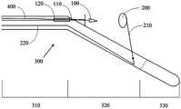
- Fig. 1is a schematic diagram of the structure of a heart valve wire setter
- Fig. 2is the schematic diagram that the heart valve wire setter forms the buckle structure
- Figure 3is a schematic structural diagram of a card part and a buckle part
- Fig. 4is the schematic diagram that the heart valve wire setter is anchored on the valve
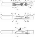
- Fig. 5is a schematic diagram of the structure of the tie device
- Figure 6is a schematic diagram of the structure of the thread trimmer
- Figure 7is a schematic diagram of mitral valve placement
- Figure 8is a schematic diagram of mitral valve wire placement to reduce valve interval
- Figure 9is a schematic diagram of mitral valve wire placement to reduce valve interval
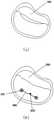
- Figure 10is a schematic diagram of tricuspid valve placement to reduce valve spacing.
- 200-Second snap part201-Card part, 202-Annular through hole, 203-Tag, 204-Protection part, 205-Support layer, 206-Biocompatible layer, 207-Sharp protrusion, 210-Section Two snap parts connectors, 211-shaft hole, 220-second power transmission part;
- 600-wire knotting device600-wire knotting device, 610-wire knotting guide, 620-wire knotting card, 630-wire tube, 640-stop part;
- 700-Thread cutter710-Thread cutter guide, 720-Scissors, 721-Blade, 722-Elastic connector, 723-Shear plate, 724-Wire groove, 730-Power transmission part.
- a heart valve wire placement devicewhich includes: a catheter, a first snap member, and a second snap member, at least partially penetrated through the catheter and fixed with the first snap member
- the connecting wireis at least partially penetrated through the first power transmission part in the conduit, and the first power transmission part and the first buckle part can be disconnected
- the conduitcomprises: an extension section and an operation section in sequence and an optional protective segment; the proximal end of the operating segment is provided with a first snap-fit part direction guide, and the first snap-fit part direction guide is provided with a guide channel for the first power transmission part to pass through ;
- a second snap-fit connectoris provided on the operating section, and the second snap-fit connector is rotatably connected to the conduit at the distal end; a second power at least partially penetrated in the conduit a transmission part, the second power transmission part is connected with the second buckle part connector, and the second buckle part connector and the second buckle part can be disconnected; thus, when the first When the two power transmission components apply the opening rotational power
- the heart valve wire setter described in the present applicationis used to anchor a wire on the heart valve, and the wire can be a medical puller wire or a medical suture, and the valve repair technology is inserted through a catheter to push the operation segment to the position of the heart valve , and then through the power provided by the first power transmission part and the second power transmission part, the first snap part and the second snap part move toward each other from both sides of the valve to form a snap connection , and positioned on the valve, the connectors of the first power transmission member and the second buckle member are disengaged, and the first buckle member, the second buckle member, and the first buckle member
- the fixedly connected wireis anchored on the valve, and the wire connected with the first snap member is formed on the side of the atrium, and the wire can exert traction on the valve by means of the snap structure, so as to perform treatment.
- the snap connection in this applicationhas the meaning commonly understood by those skilled in the art, and specifically refers to the embedded locking connection between the first snap part and the second snap part, which includes sharp
- the headis used to puncture the valve, and also includes an elastic part with certain flexibility, the elastic part deforms and rebounds during the snap connection, so as to realize the connection between the first snap part and the second snap part. atresia.
- the valvecan be quickly punctured at a single point of action to form a snap-fit connection, the operation time is short, and the valve works well. impact is minimal.
- the wireis connected with the first snap member, so that the anchored wire is located on the atrium side of the valve, which does not affect the work of the valve and the chordae tendineae, and is also very beneficial to subsequent operations.
- the "moving toward each other" mentioned in this applicationincludes both the two parts approaching each other at the same time, and the two parts moving in succession to approach each other.
- the present applicationcontrols the traveling direction of the first buckle member by setting a first buckle member direction guide, and the first buckle member direction guide is provided with a guide for the first power transmission member to pass through.
- the guide channel of the guide channelpoints to the second snap part in the open state, when the first power transmission part applies longitudinal power to the first snap part (that is, along the axis of the catheter direction power) to ensure that the first snap member travels according to the prescribed route.
- the setting form of the guide channelis not particularly limited, it only needs to play the required guiding role, for example, it can be a closed channel, an open channel, or a channel composed of a plurality of position fixing devices that can play a guiding role (such as a channel). multiple collars) etc.
- a second snap member connector rotatably connected to the catheteris provided at the distal end of the operating section.
- the adjustment of Drive the second snap member to travel from the catheter to a predetermined position on the ventricle side, combined with the first snap member direction guide, the first snap member and the second snap membercan be formed. Snap connection.
- the first power transmission component and the first snap component, the second snap component connector and the second snap componentare all detachable, so that the After the first snap member and the second snap member form a snap connection and are positioned on the valve, the connectors of the first power transmission member and the second snap member are disengaged as soon as possible to avoid affecting the valve. Work.
- the form of the detachable connectionis not particularly limited, as long as the desired purpose can be achieved.
- the present applicationis also provided with an optional protection segment, which is located at the end of the catheter and plays a role in protecting the heart during the operation, preventing the catheter from damaging the heart during the operation.
- the protective segmentmay be formed by a flexible shape and/or material.
- the first snap-fitting partis a snap-fitting part
- the second snap-fitting partis a snap-fitting part
- the first snap-fitting partis a snap-fitting part
- the second snap-fitting partis a snap-fitting part part.
- the snap connectionis an embedded latching connection between two components, which includes a snap component and a buckle component.
- the buckle component in the present applicationis a component that includes a sharp head piercing the valve, which passes through the valve. After inserting/passing through the card part, a snap connection is formed.
- the first snap partcan be a card part or a snap part; correspondingly, the second snap part can be a snap part or a card part.
- the first snap partis a snap part
- the second snap partis a snap part
- this structurecan protect the heart more effectively, and the snap part with a sharp head can The catheter exits immediately into the card member, reducing the potential for damage to the heart.
- the terms embedded and penetratedhave the same meaning when describing the kinematic relationship between the buckles, and both refer to the process in which at least a part of the finger buckle component enters the through hole of the buckle component to form a buckle connection.
- the direction guide of the first snap memberis one or more metal tubes fixedly arranged on the conduit, and the inside of the metal tubes is the guide channel.
- the metal pipeis a relatively convenient setting. It can be either a closed pipe or an open pipe with an opening in the pipe wall, as long as it can guide the first snap part to form a snap connection with the second snap part. .
- the fixed angleis a right angle or an acute angle, such as about 90 degrees, 20 to 60 degrees, or 30 to 50 degrees.
- the second snap-fit connectoropens and rotates under the action of the second power transmission member, and forms a fixed angle with the operating section.
- the second snap member connectordrives the second snap member to travel to the ventricular side of the valve.
- the The second snap parttravels to a suitable position on the ventricle side of the valve with the smallest moving distance, and fits with the shape of the valve. According to the size of the rotation angle and the length of the connector of the second snap part, the second snap part can be adjusted in the ventricle. The side is close to the position of the valve, so that the anchoring position of the snap-fitting part on the valve can be easily adjusted.
- an end of the first power transmission memberforms an external thread
- a rear portion of the first buckle memberforms an inner thread
- the first power transmission member and the first buckle memberpass through the The internal thread and the external thread form a detachable connection.
- the conduitis provided with a side opening at the operating section, and the first snap part, the second snap part and the second snap part connector are provided on the conduit side opening.
- the length of the side openingshould be greater than the length of the second snap-fit connector, and the width should enable the first snap-fit and the second snap-fit to travel from the side opening to a predetermined position.
- the catheteris provided with a rotating shaft at the distal end of the operating section
- the second snap component connectoris provided with a shaft hole
- the second snap component connectorpasses through the rotating shaft and the A shaft hole is rotatably connected to the conduit.
- the second power transmission membercan be connected to the distal end of the second snap member connector relative to the position of the shaft hole. , and can also be connected to the proximal end relative to the position of the shaft hole, and the second latching member connector can be rotated by the pushing and pulling of the second power transmission member.
- the first power transfer memberincludes a high memory wire.
- the high-memory steel wirehas high strength, good flexibility and light weight, and is the preferred material for the first power transmission component.
- the first power transmission member made of high-memory steel wirerecovers its shape after being protruded from the guide passage, thereby advancing the first latching member in a predetermined direction and forming with the second latching member Snap connection.
- the operation sectionneeds to penetrate the atrium and ventricle of the heart at the valve, and its length should be in line with the size of the human heart, and the second snap-fit connector drives the second snap-fit member to travel on the ventricular side valve in the ventricle , and a suitable length can locate the second snap-fit member at a suitable position of the valve, for example, near the root of the valve or at the valve annulus.
- a suitable lengthcan locate the second snap-fit member at a suitable position of the valve, for example, near the root of the valve or at the valve annulus.
- the length of the operating segmentis 2 cm to 3 cm
- the length of the second snap-fit connectoris 1.8 to 2.7 cm .
- the length of the operating segmentis 1 cm to 7 cm.
- the second snap memberis snapped onto an end of the second snap member connector.
- the second snap partcan be disengaged from the connector of the second snap part through the pulling of the first power transmission part, and those skilled in the art can appropriately set the snap connection
- the devicecan be quickly disengaged from the connector of the first power transmission member and the second snap member through the operation on the atrial side, thereby reducing the adverse effect on the valve operation.
- the card memberhas an annular through hole into which the buckle member is embedded, and a tab disposed in the annular through hole, the tab is an elastic member with certain flexibility, and the buckle
- the componenthas a sharp head that can pass through the annular through hole, and an extension connected with the sharp head and has at least one slot, when the sharp head passes through the annular through hole, the The tabs press against the slots to form a snap connection.
- Those skilled in the artcan reasonably set different snap connection structures. For example, there can be multiple snap slots. When there are multiple snap slots, the snap can be adjusted according to the thickness of the valve and the number of snap slots to pass through. gaps between the buckle structures, so that the buckle structures can better adapt to the thickness of the valve.
- the cross-sectional area of the clip partshould not be too small, otherwise it may cause concentrated stress on a certain point of the valve.
- the cross section of the card memberrefers to the surface of the card member in contact with the valve, and those skilled in the art can choose according to the actual situation. , to avoid damage to the valve.
- the buckle memberalso has a tail portion connected to the extension portion, so as to be better secured to the valve.
- the contact area of the tail with the valveshould not be too small, otherwise it may cause concentrated force on a certain point of the valve.
- Those skilled in the artcan choose according to the actual situation, for example, setting the cross-sectional area of the tail excluding the extension is greater than 0.1 square centimeter, which can disperse the force and avoid damage to the valve.
- the gap between the tail portion of the snap member and the snap memberis 0.5 mm to 2 mm.
- the distance of the above-mentioned gapdepends on the thickness of the valve, so that the buckle structure can clamp the valve without sliding between the valve and the valve, so as to prevent the extension part in the buckle structure from damaging the valve.
- the card memberhas a protective portion corresponding to the sharp head of the buckle member, and the protective portion is rounded on the outside.
- the protective portionis rounded on the outside.
- the sharp headIn order to enable the buckle member to puncture the valve, it has a sharp head.
- the sharp headafter the sharp head of the buckle member is inserted into the card member to form a snap connection, the sharp head will extend to the card On the other side of the part, in order to prevent the sharp head from piercing other parts of the heart, the card part has a corresponding round protection part to cover the sharp head.
- the heart valve wire setteris provided with a visualization marker on at least one component, for example, a visualization marker is provided on the distal end of the catheter.
- the visualization markercan assist the doctor to see the position of the wire inserter in the patient's body in real time, and can precisely control the operation. There is no limitation on the development of the mark itself, and those skilled in the art can choose according to actual needs.
- the tail portion of the buckle member and the card membereach independently comprise at least two layers: a support layer that provides structural support, and a biocompatible layer that provides biocompatibility.
- a support layerthat provides structural support
- a biocompatible layerthat provides biocompatibility.
- the biocompatible layeris set on the side that is in direct contact with the heart valve.
- the support layerhas a plurality of sharp protrusions of 0.3mm to 2.0mm (eg, 0.3mm to 0.8mm, such as 0.5mm) extending toward the biocompatible layer to strengthen the valve fixed effect.
- the sharp protuberancesmake the snapping structure formed on the valve, the snapping part and the snapping part tightly bite the valve like teeth, so as to strengthen the fixing effect of the valve.
- the support layer providing structural supportis made of metal or rigid plastic
- the biocompatible layer providing biocompatibilityis made of thermoplastic polyurethane material.
- Thermoplastic polyurethane materialis a commonly used biocompatible material, which is very suitable for use in the technical solution of the present application.
- the protective segmenthas a rounded tip made of a soft material, such as a thermoplastic polyurethane material, capable of protecting the heart from the hard parts of the catheter.
- the protection segmentis a pigtail segment made of a soft material, the outer diameter of the tube at the end is 1-3mm, a circle with a diameter of 7mm to 13mm is formed at the end, and there is a guide wire The arrangement of the through hole enables the pigtail segment to abut against the bottom of the atrium, which plays a stabilizing role during the operation.
- the specific length of the protective segmentcan be specifically adjusted according to the condition of the heart and the specific shape of the protective segment.
- a wire binding devicecomprising: a wire binding guide tube; a wire binding clip disposed at the end of the wire binding guide tube, with an opening that is automatically closed; and a wire tube at least partially passing through the In the conduit and the end portion is pre-clamped in the opening of the wire-tie card; the blocking portion on the wire-tie guide is arranged next to the wire-tie card.
- the tie cardmay be a clip.
- the tie cardis a self-closing loop formed from high-memory steel sheets.
- the wire binderfurther includes a wire pre-threaded in the wire conduit.
- the present applicationalso provides a thread trimmer, comprising: a thread trimmer conduit; scissors arranged at the end of the thread trimmer conduit; a power transmission part, the power transmission part is connected with the scissors, so that the scissors can be executed Cut operation.
- a thread trimmercomprising: a thread trimmer conduit; scissors arranged at the end of the thread trimmer conduit; a power transmission part, the power transmission part is connected with the scissors, so that the scissors can be executed Cut operation.
- the scissorsinclude two blades, and under the action of the power transmission component, the two blades move toward each other to complete the cutting operation.
- the scissorsinclude a blade connected to the power transmission member, and a shearing plate connected to the blade through an elastic connection and arranged perpendicular to the blade, the elastic connection allows the A certain gap is maintained between the blade and the shearing plate, and a wire groove is also provided on the side wall of the end of the wire-cutting conduit, and the wire groove can guide the wire into the gap between the blade and the shearing plate.
- the power transmission partdrives the blade to move and completes the shearing operation on the shearing board. After the power transmission part is released, the elastic connecting piece automatically rebounds the blade to the initial position.
- the bladeis arranged parallel to the axis of the wire cutting conduit, and the shearing plate is arranged perpendicular to the axis of the wire cutting conduit.
- the number of the blades and the shearing platesare both two, and the two helically extending wire grooves are correspondingly provided.
- the two blades, shearing plates, and wire groovesare oppositely arranged in the wire-cutting conduit, and the spirally extended wire grooves can keep the wire stable and avoid detachment, so that the two wires can be simultaneously cut in the wire-cutting guide.
- the contralateral side within the cathetercompletes the cut.
- the present applicationalso provides a method for treating heart disease, comprising: fixing the first end of the first wire on the first heart valve, and fixing the first end of the second wire on the second heart valve, A knot is formed between the first wire and the second wire by the second end of the first wire and the second end of the second wire, thereby forming a knot between the first heart valve and the second heart valve A traction is formed between the first heart valve and the second heart valve, so that the distance between the first heart valve and the second heart valve is reduced, and the first heart valve and the second heart valve are the same or different valves.
- the method for treating heart diseaseincludes forming a first snap member and a first snap member on the first heart valve, the first snap member passing through the first heart
- the valveforms a snap connection with the first clip part, and the first end of the first wire is connected with at least one of the first clip part and the first clip part; on the second heart valve A second clip part and a second clip part are formed, the second clip part passes through the second heart valve to form a clip connection with the second clip part, and the first end of the second wire is connected to the second clip part.
- At least one of the second snap member and the second buckle memberis connected, and the first heart valve and the second heart valve are the same or different valves.
- the method for treating heart diseasewherein the step of "fixing the first end of the first wire on the first heart valve” is completed by the heart valve wire setter, "fixing the first end of the first wire on the first heart valve”.
- the step of fixing the first ends of the two wires on the second heart valveis completed by the described heart valve wire setter.
- the present applicationalso provides a heart valve treatment system, which includes at least two wire inserters described in the present application, at least one wire binding device, and at least one wire cutter.
- the connectoris any of the connectors described herein.
- the wire knotteris any of the wire cutters described herein.
- the material selection and preparation method of the thread setter, thread knotter and thread trimmer in the present applicationcan be selected by those skilled in the art according to the prior art, and may refer to prior art documents or existing related products.
- a heart valve wire setterwhich includes:
- a buckle force transmission partat least partially penetrated in the conduit, the buckle force transmission part and the buckle part being detachable;
- the conduitcomprises in turn: an extension section, an operating section and an optional protective section;
- the proximal end of the operating segmentis provided with a buckle member direction guide, and the buckle member direction guide is provided with a guide channel for the buckle force transmission member to pass through, (the direction of the guide channel points to the buckle member in the open state, When the buckle force transmission member applies longitudinal power to the buckle member, it is ensured that the buckle member travels according to the prescribed route);
- a card part connectoris provided on the operation section, and the card part connector is rotatably connected with the conduit;
- a card power transmission memberat least partially penetrated in the conduit, the card power transmission member is connected with the card member connector, and the card member connector is detachable from the card member;
- the card part connectorrotates and forms a fixed angle with the operating section, the direction of the guide channel is directed to the card part, and this
- the buckle force transmission memberapplies forward power to the buckle member, the buckle member forms a snap connection with the card member.
- This embodimentprovides a device for treating mitral insufficiency, which includes a heart valve wire setter, a wire binding device 600 and a wire cutter 700 .
- the heart valve wire placement deviceincludes:
- the catheter 300includes an extension section 310, an operation section 320 and a protection section 330 in sequence, the protection section 330 has a rounded end made of thermoplastic polyurethane material, and a development mark is provided at the distal end of the operation section 320 , the operating section 320 is provided with a side opening 321;
- a first snap part 100 and a second snap part 200wherein the first snap part 100 is a snap part 101, and the second snap part 200 is a snap part 201;
- the wire 400 which is passed through the conduit 300 and is fixedly connected with the first snap member 100 , the first power transmission member 110 and the second power transmission member 220are passed through the conduit 300 .
- the first power transmission member 110is made of high-memory steel wire and has an outer thread formed at the end, and an inner thread is formed at the rear of the first snap member 100.
- the first power transmission member 110is connected to the first
- the snap-fit component 100is detachably connected through the internal thread and the external thread.
- the proximal end of the operating section 320is provided with a first buckling member direction guide 120, and the first buckling member direction guide 120 is a metal tube fixed on the catheter 300, A guide passage through which the first power transmission member 110 passes.
- the operating section 320is 3 centimeters long, and its distal end is provided with a rotating shaft 322, which is rotatably connected to the rotating shaft 322 with a second snap-fit connector 210 provided with a corresponding shaft hole.
- the second power transmission member 220Connect with the second snap part connector 210 at the distal end of the shaft hole, so that by pulling the second power transmission part 220 the second snap part connector 210 can be rotated to open and connect with the
- the operating section 320forms an included angle of 45 degrees, and at this time, the direction of the guide channel points to the second snap member 200 ; the length of the second snap member connector 210 is 2.5 cm, and the second snap member is 2.5 cm long. 200 is snapped on the end of the second snap-fit connector 210 .
- the first snap part 100 , the second snap part 200 and the second snap part connector 210are disposed at the side opening 321 of the operation section 320 .
- the card member 201has an annular through hole 202 into which the buckle member 101 is embedded and a tab 203 disposed in the annular through hole 202, the tab 203 is An elastic part with certain flexibility
- the buckle part 101has a sharp head 102 embedded in the annular through hole 202, and an extension part 104 connected with the sharp head 102 and having a plurality of card grooves 103
- the For the tail portion 105 connected by the extension portion 104when the sharp head 102 is inserted into the annular through hole 202, the tab 203 presses against the slot 103, thereby forming a snap connection.
- the cross-sectional area of the clip part 201 and the tail part 105 of the buckle part 101 excluding the extension part 104is about 0.11 square centimeters. The gap between them can be 1mm.
- the operating segment 320is pushed to the position of the heart valve, and then the power provided by the first power transmission part 110 and the second power transmission part 220 is used to make
- the buckle member 101 and the clip member 201move toward each other from both sides of the valve 500 to form a snap connection and are positioned on the valve 500 .
- the first power transmission part 110can be pulled to disengage the snap part 201 from the second snap part connector 210, and then the first power transmission part 110 is rotated to make After being disengaged from the buckle member 101 , the buckle member 101 , the clip member 201 , and the wire 400 fixedly connected to the buckle member 101 are anchored on the valve 500 .
- the card member 201may also be provided with a smooth protection portion 204 to cover the sharp head 102 .
- the card part 201includes a support layer 205 for providing structural support, and a biocompatibility layer 206 for providing biocompatibility.
- the tail part 105 of the buckle part 101also has the above two-layer structure, wherein the biological
- the compatibility layer 206is made of thermoplastic polyurethane material and is disposed on the contact surface of the valve 500 .
- the present embodimentcan also select the following structure: the card member 201 includes a support layer 205 that provides structural support, and a biocompatibility layer 206 that provides biocompatibility, wherein the support layer 205 There are a plurality of 0.5mm sharp protrusions 207 on the upper part, extending toward the biocompatible layer 206, and the tail portion 105 of the buckle member 101 also has the above-mentioned two-layer structure and sharp protrusions, so as to strengthen the fixation of the valve.
- the support layer 205is made of metal material.
- the heart valve wire setterquickly punctures the valve on a single action point to form a snap connection, has a short operation time, and has minimal influence on the valve operation.
- the wire 400is connected with the first snap member 100, so that the anchored wire 400 is located on the atrium side of the valve, which does not affect the operation of the valve and the chordae tendineae, and is also very beneficial to subsequent operations.
- the wire binding device 600includes: a wire binding conduit 610; A ring formed by a high-memory steel sheet that automatically closes the opening; a wire tube 630, which is at least partially penetrated in the wire-tie guide 610 and its end is pre-clamped in the opening of the wire-tie card 620; The wire-tie card 620 is disposed on the blocking portion 640 on the wire-tie guide 610 . The wire tie device 600 automatically closes the wire tie card 620 to complete the wire tie by withdrawing the wire tube 630 pre-clamped in the opening of the wire tie card 620 .
- the thread trimmer 700includes a thread trimmer duct 710; scissors 720 disposed at the end of the thread trimmer duct 710; and a power transmission member 730.
- the scissors 720include two blades 721 connected with the power transmission member 730, and a shearing plate 723 connected with the blades 721 through elastic connecting pieces 722 and arranged perpendicular to the blades 721.
- the elastic connecting pieces 722is a spring, the blade 721 is arranged in parallel with the axis of the thread trimmer duct 710, the elastic connecting piece 722 keeps the blade 721 and the shearing plate 723 a certain gap, the side of the end of the thread trimmer duct 710
- the wallis also provided with two helically extending wire grooves 724 correspondingly, the wire grooves 724 can guide the wire into the gap between the blade 721 and the shearing plate 723, so that the two wires can be guided in the space at the same time.
- the power transmission member 730drives the blade 721 to move and completes the cutting operation on the shearing plate 723. After the power transmission member 730 is released, the elastic connection member 722 The blade 721 automatically springs back to the initial position.
- the devicetreats mitral regurgitation by:
- a guide wireis set through the femoral vein and through the right atrium through the interatrial septum.
- the heart valve wire setteris introduced through the femoral vein, and the operating segment 320 is pushed to the mitral valve by means of a developing marker.
- the first end of the first wireis fixed on the first heart valve, and the first end of the second wire is fixed on the second heart valve opposite to the first heart valve .
- the cutter 700cuts the thread, withdrawing the thread cutter and the cut thread.
- Fig. 8(a)is the mitral valve with incomplete regurgitation
- Fig. 8(b), (c)is the mitral valve that has been completely closed after treatment, those skilled in the art can use the cross knot rope traction between multiple snap connectors , to achieve better treatment effect.
- FIG(a) and (b)show another example.
- the two The root wireprovides traction on the valve insufficiency, thereby reducing the valve gap.
- This embodimentprovides a device for treating tricuspid regurgitation, which includes a heart valve wire setter, a wire binding device and a wire cutter.
- the settings of the heart valve wire setter, the wire binding device and the wire cutterare the same as those of the embodiment 1, the difference is that the catheter in the embodiment 2 is shorter.
- Figure 10(a)shows an insufficiency tricuspid valve, treated by:
- the guide wireis set through the jugular vein puncture, and then the heart valve wire setter is introduced through the jugular vein, and the operating segment is pushed to the tricuspid valve with the help of the visualization indicator, and the first wire is inserted by the heart valve wire setter.
- the first end of the wireis fixed on the first heart valve, and the first end of the second wire is fixed on the second heart valve opposite to the first heart valve.
- the knotteris used to form a knot between the second end of the first wire and the second end of the second wire, thereby forming a knot between the first wire and the second wire.
- a tractionis formed between the first heart valve and the second heart valve, so that the gap between the first heart valve and the second heart valve is reduced, the thread is cut by the thread trimmer, and the thread trimmer is withdrawn and cut lines.
- the first end of the third wirecan also be selected to be fixed on the third heart valve opposite to the first heart valve and the second heart valve, and the wire binding device is used to make the A knot is formed between the second ends of the first thread, the second thread and the third thread, so as to form traction for the valve insufficiency and reduce the valve gap.
Landscapes
- Health & Medical Sciences (AREA)
- Life Sciences & Earth Sciences (AREA)
- Surgery (AREA)
- General Health & Medical Sciences (AREA)
- Public Health (AREA)
- Biomedical Technology (AREA)
- Heart & Thoracic Surgery (AREA)
- Veterinary Medicine (AREA)
- Engineering & Computer Science (AREA)
- Animal Behavior & Ethology (AREA)
- Molecular Biology (AREA)
- Nuclear Medicine, Radiotherapy & Molecular Imaging (AREA)
- Medical Informatics (AREA)
- Cardiology (AREA)
- Oral & Maxillofacial Surgery (AREA)
- Transplantation (AREA)
- Vascular Medicine (AREA)
- Rheumatology (AREA)
- Prostheses (AREA)
- Surgical Instruments (AREA)
Abstract
Description
Translated fromChinese本发明涉及医疗器械技术领域,具体为一种心脏瓣膜置线器,以及采用该心脏瓣膜置线器治疗心脏疾病的方法。The invention relates to the technical field of medical devices, in particular to a heart valve wire setter and a method for treating heart diseases by using the heart valve wire setter.
心脏瓣膜控制着血液在心脏内的流向,其中,二尖瓣位于左心房和左心室之间,三尖瓣位于右心房和右心室之间,功能正常的心脏瓣膜就像单向阀,在心脏内有规律地开合启闭,让血液以单一方向从心房流向心室。心瓣病变导致瓣膜关闭不全,会出现血液反流,例如,常见的心脏瓣膜疾病二尖瓣反流(MR)就是由于二尖瓣关闭不全引起的,流行病学资料显示,我国六十岁以上人群中MR患病率高达13.4%,需要临床干预的中重度MR患者约1000万,未来随着社会的发展和人口的老龄化,MR的发病率还将呈上升态势,MR的介入器械目前已成为国内外心血管器械研发的重点方向之一。The heart valves control the flow of blood in the heart. Among them, the mitral valve is located between the left atrium and the left ventricle, and the tricuspid valve is located between the right atrium and the right ventricle. It opens and closes regularly, allowing blood to flow from the atrium to the ventricle in a single direction. Heart valve disease leads to valve insufficiency and blood regurgitation occurs. For example, the common heart valve disease mitral regurgitation (MR) is caused by mitral valve insufficiency. Epidemiological data show that in my country, people over 60 years old in China The prevalence of MR in the population is as high as 13.4%, and there are about 10 million moderate-to-severe MR patients requiring clinical intervention. In the future, with the development of society and the aging of the population, the incidence of MR will continue to rise. It has become one of the key directions of cardiovascular device research and development at home and abroad.
相对于外科手术治疗创伤大、术后疼痛明显、恢复慢、风险高等缺点,微创介入修复技术成为新的治疗手段,国内外用微创介入方法治疗二尖瓣疾病的产品较多,也有少量微创介入方法治疗三尖瓣疾病的产品,个别为可用于二尖瓣和三尖瓣通用型产品。如MitraClip、PASCAL、ValveClam、Cardioband、Mitralign、NeoChord等均采用了微创介入修复技术,其中,Evalve公司的MitraClip是国际上唯一获批上市治疗MR的微创介入器械,价格昂贵,成功率低于60%,容易导致二尖瓣狭窄。Compared with the shortcomings of surgical treatment of large trauma, obvious postoperative pain, slow recovery and high risk, minimally invasive interventional repair technology has become a new treatment method. Products for the treatment of tricuspid valve disease by invasive interventional methods, some of which are general-purpose products that can be used for mitral valve and tricuspid valve. For example, MitraClip, PASCAL, ValveClam, Cardioband, Mitralign, NeoChord, etc. all adopt minimally invasive interventional repair technology. Among them, Evalve's MitraClip is the only minimally invasive interventional device approved for the treatment of MR in the world. It is expensive and has a lower success rate than 60%, prone to mitral stenosis.
因此,需要一种结构简单、成本低廉、易于操作、效果理想的通用型心脏瓣膜微创介入修复器械。Therefore, there is a need for a universal heart valve minimally invasive interventional repair device with simple structure, low cost, easy operation and ideal effect.
发明内容SUMMARY OF THE INVENTION
本发明所要解决的病人的心脏瓣膜间隔变大,造成血液回流,供血不足的情况,本申请的发明人发明了一种心脏瓣膜置线器、与置线器配合使用的结线器和剪线器,以及采用该置线器治疗心脏疾病的方法。To solve the problem that the heart valve interval of the patient becomes larger, resulting in blood backflow and insufficient blood supply, the inventor of the present application has invented a heart valve wire setter, a wire binding device and a wire trimmer used in conjunction with the wire setter. device, and a method for treating heart disease using the wire placement device.
本发明解决上述技术问题的技术方案包括以下内容:The technical scheme that the present invention solves the above-mentioned technical problem includes the following content:
实施方式1.一种心脏瓣膜置线器,其包括:导管,第一卡扣部件,第二卡扣部件,至少部分穿设在所述导管中并且与所述第一卡扣部件固定连接的线,至少部分穿设在所述导管中的第一动力传递部件,所述第一动力传递部件与所述第一卡扣部件可脱离连接;Embodiment 1. A heart valve wire placement device, comprising: a catheter, a first snap member, and a second snap member, at least partially pierced through the catheter and fixedly connected to the first snap member. a wire, at least partially passing through the first power transmission part in the conduit, the first power transmission part and the first snap part can be disconnected;
所述导管依次包括:延伸段、操作段和任选的保护段;所述操作段的近端设置有第一 卡扣部件方向引导器,所述第一卡扣部件方向引导器上设置有供所述第一动力传递部件通过的引导通道;所述操作段上设置有第二卡扣部件连接器,所述第二卡扣部件连接器在远端与所述导管可旋转地连接;The catheter sequentially includes: an extension section, an operating section, and an optional protective section; the proximal end of the operating section is provided with a first snap member direction guide, and the first snap member direction guide is provided with a supply for a guide channel through which the first power transmission component passes; a second snap-fit connector is provided on the operating section, and the second snap-fit connector is rotatably connected to the catheter at the distal end;
至少部分穿设在所述导管中的第二动力传递部件,所述第二动力传递部件与所述第二卡扣部件连接器连接,所述第二卡扣部件连接器与所述第二卡扣部件可脱离连接;a second power transmission member at least partially penetrated in the conduit, the second power transmission member is connected with the second snap member connector, and the second snap member connector is connected with the second snap member The buckle part can be disconnected;
从而使得,当所述第二动力传递部件给第二卡扣部件连接器施加开启的旋转动力时,第二卡扣部件连接器旋转并且与所述操作段形成固定角度,所述引导通道的方向指向所述第二卡扣部件,此时当所述第一动力传递部件给所述第一卡扣部件施加前进的动力时,所述第一卡扣部件与所述第二卡扣部件形成卡扣连接。Thereby, when the second power transmission part applies the opening rotational power to the second snap part connector, the second snap part connector rotates and forms a fixed angle with the operating section, the direction of the guide channel Pointing to the second snap part, when the first power transmission part applies forward power to the first snap part, the first snap part and the second snap part form a latch Buckle connection.
实施方式2.根据实施方式1所述的心脏瓣膜置线器,其中所述第一卡扣部件为扣部件,所述第二卡扣部件为卡部件;或者,所述第一卡扣部件为卡部件,所述第二卡扣部件为扣部件。Embodiment 2. The heart valve wire inserter according to Embodiment 1, wherein the first buckle component is a buckle component, and the second buckle component is a buckle component; or, the first buckle component is a A clip part, the second clip part is a clip part.
实施方式3.根据实施方式1所述的心脏瓣膜置线器,其中所述第一卡扣部件方向引导器为固定设置在所述导管上的一个或多个金属管,所述金属管的内部即为所述的引导通道。Embodiment 3. The heart valve wire inserter according to Embodiment 1, wherein the first snap member direction guide is one or more metal tubes fixedly arranged on the catheter, and the inside of the metal tube is That is, the guide channel.
实施方式4.根据实施方式1所述的心脏瓣膜置线器,其中所述固定角度直角或者锐角,例如约90度,20度至60度,或30度至50度。Embodiment 4. The heart valve wire inserter of Embodiment 1, wherein the fixed angle is a right angle or an acute angle, eg, about 90 degrees, 20 degrees to 60 degrees, or 30 degrees to 50 degrees.
实施方式5.根据实施方式1所述的心脏瓣膜置线器,其中所述第一动力传递部件的末端形成外螺纹,所述第一卡扣部件的后部形成内螺纹,所述第一动力传递部件与所述第一卡扣部件通过所述的内螺纹和外螺纹形成可脱离连接。Embodiment 5. The heart valve wire inserter according to Embodiment 1, wherein a distal end of the first power transmission member forms an external thread, a rear portion of the first snap member forms an internal thread, and the first power transmission member forms an internal thread. The transmission member and the first snap member are detachably connected through the inner thread and the outer thread.
实施方式6.根据实施方式1或2所述的心脏瓣膜置线器,其中,所述导管在所述操作段处设置有侧面开口,所述第一卡扣部件、所述第二卡扣部件和所述第二卡扣部件连接器设置在所述导管的侧面开口处。Embodiment 6. The heart valve wire placement device according to Embodiment 1 or 2, wherein the catheter is provided with a side opening at the operating section, the first snap part and the second snap part and the second snap-fit connector is provided at the side opening of the conduit.
实施方式7.根据实施方式1所述的心脏瓣膜置线器,其中,所述导管在所述操作段的远端设置有转轴,所述第二卡扣部件连接器上设置有轴孔,所述第二卡扣部件连接器通过所述转轴和轴孔与所述导管可旋转地连接。Embodiment 7. The heart valve wire placement device according to Embodiment 1, wherein the catheter is provided with a rotating shaft at the distal end of the operating section, and the second snap member connector is provided with a shaft hole, so The second snap-fit connector is rotatably connected to the conduit through the shaft and the shaft hole.
实施方式8.根据实施方式1所述的心脏瓣膜置线器,其中所述第一动力传递部件包括高记忆性钢丝。Embodiment 8. The heart valve wire inserter of Embodiment 1, wherein the first power transmission member comprises a high memory wire.
实施方式9.根据实施方式1所述的心脏瓣膜置线器,其中,所述操作段的长度为2厘米至3厘米;所述第二卡扣部件连接器的长度为1.8至2.7厘米。Embodiment 9. The heart valve wire inserter according to Embodiment 1, wherein the length of the operation segment is 2 cm to 3 cm; and the length of the second snap member connector is 1.8 to 2.7 cm.
实施方式10.根据实施方式1所述的心脏瓣膜置线器,其中,所述第二卡扣部件卡接在所述第二卡扣部件连接器的端部。Embodiment 10. The heart valve wire inserter according to Embodiment 1, wherein the second snap member is snapped on an end of the second snap member connector.
实施方式11.根据实施方式2所述的心脏瓣膜置线器,其中,所述卡部件具有供所述 扣部件穿过的环形通孔和设置在所述环形通孔内的卡舌,所述卡舌为具备一定柔韧性的弹性部件,所述扣部件具有能够穿过所述环形通孔的尖锐头部,以及与所述尖锐头部连接的具有至少一个卡槽的延伸部,当所述尖锐头部穿过所述环形通孔时,所述卡舌顶住所述卡槽,从而形成卡扣连接。Embodiment 11. The heart valve wire inserter according to Embodiment 2, wherein the clip member has an annular through hole through which the buckle member passes and a tab disposed in the annular through hole, the The tab is an elastic part with certain flexibility, the buckle part has a sharp head that can pass through the annular through hole, and an extension part connected with the sharp head and having at least one slot, when the When the sharp head passes through the annular through hole, the tab presses against the slot so as to form a snap connection.
实施方式12.根据实施方式11所述的心脏瓣膜置线器,其中所述卡部件的横截面积大于0.1平方厘米,从而能够提供较好的力分散。Embodiment 12. The heart valve wire inserter of Embodiment 11, wherein the cross-sectional area of the clip member is greater than 0.1 square centimeters so as to provide better force dispersion.
实施方式13.根据实施方式11或12所述的心脏瓣膜置线器,其中所述扣部件还具有与所述延伸部连接的尾部。在一些实施方式中,所述尾部除去所述延伸部的横截面积大于0.1平方厘米。Embodiment 13. The heart valve wire inserter of Embodiment 11 or 12, wherein the buckle member further has a tail portion connected to the extension. In some embodiments, the cross-sectional area of the tail excluding the extension is greater than 0.1 square centimeters.
实施方式14.根据实施方式13所述的心脏瓣膜置线器,其中所述第一卡扣部件与所述第二卡扣部件形成卡扣连接之后,所述扣部件的所述尾部与所述卡部件之间的距离为0.5mm至2mm。Embodiment 14. The heart valve wire inserter according to Embodiment 13, wherein after the first snap member and the second snap member form a snap connection, the tail portion of the snap member is connected to the The distance between the card parts is 0.5mm to 2mm.
实施方式15.根据实施方式11所述的心脏瓣膜置线器,其中所述卡部件具有对应于扣部件尖锐头部的保护部,所述保护部外部圆滑。Embodiment 15. The heart valve wire inserter of Embodiment 11, wherein the clip member has a protective portion corresponding to the sharp head portion of the buckle member, the protective portion being rounded on the outside.
实施方式16.根据实施方式1所述的心脏瓣膜置线器,其中在至少一个部件上设置显影示标,例如在所述导管的远端设置显影示标。Embodiment 16. The heart valve wire inserter of Embodiment 1, wherein a visualization marker is provided on at least one component, eg, a visualization marker is provided on the distal end of the catheter.
实施方式17.根据实施方式13所述的心脏瓣膜置线器,其中所述扣部件的所述尾部和所述卡部件各自独立地包括至少两个层:提供结构支撑的支撑层,和提供生物相容性的生物相容性层。在一些实施方式中,所述支撑层上具有多个0.3mm至2.0mm的尖锐突起,伸向生物相容层,以加强瓣膜固定作用。Embodiment 17. The heart valve wire inserter of Embodiment 13, wherein the tail portion of the buckle member and the clip member each independently comprise at least two layers: a support layer that provides structural support, and a support layer that provides biological support. Compatible biocompatible layer. In some embodiments, the support layer has a plurality of sharp protrusions of 0.3 mm to 2.0 mm extending toward the biocompatible layer to enhance valve fixation.
实施方式18.根据实施方式17所述的心脏瓣膜置线器,其中所述提供结构支撑的支撑层由金属或者硬质塑料制成。Embodiment 18. The heart valve wire inserter of Embodiment 17, wherein the support layer providing structural support is made of metal or rigid plastic.
实施方式19.根据实施方式1所述的心脏瓣膜置线器,其中所述保护段具有由柔软材料制成的圆滑末端。Embodiment 19. The heart valve wire inserter of Embodiment 1, wherein the protective segment has a rounded tip made of a soft material.
实施方式20.一种结线器,其包括:结线导管;设置在结线导管端部的结线卡,具有自动闭紧的开口;线管,其至少部分穿设于所述结线导管中并且端部预卡设在所述结线卡的开口中;紧挨所述结线卡设置在所述结线导管上的阻止部。Embodiment 20. A wire binding device, comprising: a wire binding conduit; a wire binding clip arranged at the end of the wire binding conduit, with an opening that automatically closes; a wire tube at least partially penetrated through the wire binding conduit The middle and end parts are pre-clamped in the opening of the wire-tie card; the blocking part on the wire-tie guide tube is arranged next to the wire-tie card.
实施方式21.根据实施方式21所述的结线器,其中所述结线卡是由高记忆性钢片形成的自动紧闭的环。Embodiment 21. The tie-breaker of Embodiment 21, wherein the tie card is a self-closing loop formed from a high-memory steel sheet.
实施方式22.根据实施方式21所述结线器,还包括预穿设在所述线管中的线。Embodiment 22. The wire knotter of Embodiment 21, further comprising a wire pre-threaded in the wire conduit.
实施方式23.一种剪线器,其包括剪线导管;设置在剪线导管端部的剪刀;动力传递部件,所述动力传递部件与所述剪刀连接,从而能够使所述剪刀执行剪切操作。Embodiment 23. A thread trimmer comprising a thread trimmer conduit; scissors provided at the end of the thread trimmer conduit; a power transmission member connected to the scissors, thereby enabling the scissors to perform cutting operate.
实施方式24.根据实施方式23所述剪线器,所述剪刀包括与所述动力传递部件连接的 刀片,以及与所述刀片通过弹性连接件相连并与所述刀片垂直设置的剪切板,所述弹性连接件使得所述刀片与剪切板保持一定间隙,所述剪线导管端部的侧壁上还设置有线槽,所述线槽能将所述线引导到所述刀片与剪切板之间的间隙内。Embodiment 24. The thread cutter according to Embodiment 23, wherein the scissors comprise a blade connected to the power transmission member, and a shearing plate connected to the blade through an elastic connecting piece and arranged perpendicular to the blade, The elastic connecting piece keeps a certain gap between the blade and the shearing plate, and a wire groove is also provided on the side wall of the end of the wire-cutting conduit, and the wire groove can guide the wire to the blade and the shearing plate. in the gap between the plates.
实施方式25.根据实施方式24所述剪线器,其中所述刀片与所述剪线导管的轴线平行设置,所述剪切板与所述剪线导管的轴线垂直设置。Embodiment 25. The thread cutter of Embodiment 24, wherein the blade is disposed parallel to the axis of the thread trimmer conduit, and the shearing plate is disposed perpendicular to the axis of the thread trimmer conduit.
实施方式26.根据实施方式25所述剪线器,其中所述刀片与所述剪切板的数量均为两个,并对应设置有两个螺旋延伸的所述线槽。Embodiment 26. The wire cutter according to Embodiment 25, wherein the number of the blades and the shearing plates are both two, and two spirally extending wire grooves are correspondingly provided.
实施方式27.一种治疗心脏疾病的方法,其包括,将第一根线的第一端固定在第一心脏瓣膜上,将第二根线的第一端固定在第二心脏瓣膜上,通过第一根线的第二端和第二根线的第二端在第一根线和第二根线之间形成绳结,从而在所述第一心脏瓣膜和所述第二心脏瓣膜之间形成牵引,使所述第一心脏瓣膜和第二心脏瓣膜之间的距离减小,所述第一心脏瓣膜和第二心脏瓣膜为同一或者不同的瓣膜。Embodiment 27. A method of treating heart disease, comprising, securing a first end of a first wire to a first heart valve, securing a first end of a second wire to a second heart valve, by The second end of the first wire and the second end of the second wire form a knot between the first wire and the second wire, thereby between the first heart valve and the second heart valve Traction is formed to reduce the distance between the first heart valve and the second heart valve, the first heart valve and the second heart valve being the same or different valves.
实施方式28.根据实施方式27所述的治疗心脏疾病的方法,其包括,所述第一心脏瓣膜上形成有第一卡部件和第一扣部件,所述第一扣部件穿过所述第一心脏瓣膜与所述第一卡部件形成卡扣连接,所述第一根线的第一端与所述第一卡部件和所述第一扣部件中的至少一个连接;Embodiment 28. The method for treating a heart disease according to Embodiment 27, comprising forming a first snap member and a first snap member on the first heart valve, the first snap member passing through the first valve. A heart valve forms a snap connection with the first clip, and the first end of the first wire is connected with at least one of the first clip and the first clip;
所述第二心脏瓣膜上形成有第二卡部件和第二扣部件,所述第二扣部件穿过所述第二心脏瓣膜与所述第二卡部件形成卡扣连接,所述第二根线的第一端与所述第二卡部件和所述第二扣部件中的至少一个连接。The second heart valve is formed with a second clip member and a second clip member, the second clip member passes through the second heart valve to form a clip connection with the second clip member, and the second clip is connected to the second clip member. The first end of the wire is connected to at least one of the second card part and the second buckle part.
实施方式29.根据实施方式27所述的治疗心脏疾病的方法,其中“将第一根线的第一端固定在第一心脏瓣膜上”的步骤通过实施方式1-19中任一项所述的设备完成,“将第二根线的第一端固定在第二心脏瓣膜上”的步骤通过实施方式1-19中任一项所述的设备完成。Embodiment 29. The method of treating heart disease according to Embodiment 27, wherein the step of "fixing the first end of the first wire to the first heart valve" is described in any of Embodiments 1-19 The device is completed, and the step of "fixing the first end of the second wire on the second heart valve" is completed by the device described in any one of Embodiments 1-19.
本发明的所带来的预料不到的技术效果是:采用卡扣连接,将线从心房侧锚定于瓣膜上,操作简单迅速,不影响瓣膜工作,同时通过在心房侧的结线和剪线操作,将线牵引打结,能够拉近二尖瓣或三尖瓣的间隙,有效解决二尖瓣或三尖瓣反流。The unexpected technical effect brought about by the present invention is: using snap connection, the wire is anchored on the valve from the atrium side, the operation is simple and quick, and the valve work is not affected, and at the same time, through the knotting and cutting of the atrium side Line operation, pulling and knotting the line, can close the gap of the mitral valve or the tricuspid valve, and effectively solve the mitral valve or tricuspid valve regurgitation.
为了更清楚地说明本公开实施例的技术方案,下面将对说明书附图作简单地介绍,显而易见地,下面描述中的附图仅仅涉及本公开的一些实施例,而非对本公开的限制。In order to more clearly illustrate the technical solutions of the embodiments of the present disclosure, the accompanying drawings of the specification will be briefly introduced below. Obviously, the accompanying drawings in the following description only relate to some embodiments of the present disclosure, rather than limit the present disclosure.
图1为心脏瓣膜置线器结构示意图;Fig. 1 is a schematic diagram of the structure of a heart valve wire setter;
图2为心脏瓣膜置线器形成卡扣结构的示意图;Fig. 2 is the schematic diagram that the heart valve wire setter forms the buckle structure;
图3为卡部件和扣部件结构示意图;Figure 3 is a schematic structural diagram of a card part and a buckle part;
图4为心脏瓣膜置线器锚定于瓣膜上的示意图;Fig. 4 is the schematic diagram that the heart valve wire setter is anchored on the valve;
图5为结线器结构示意图;Fig. 5 is a schematic diagram of the structure of the tie device;
图6为剪线器结构示意图;Figure 6 is a schematic diagram of the structure of the thread trimmer;
图7为二尖瓣置线示意图;Figure 7 is a schematic diagram of mitral valve placement;
图8为二尖瓣置线减小瓣膜间隔示意图;Figure 8 is a schematic diagram of mitral valve wire placement to reduce valve interval;
图9为二尖瓣置线减小瓣膜间隔示意图;Figure 9 is a schematic diagram of mitral valve wire placement to reduce valve interval;
图10为三尖瓣置线减小瓣膜间隔示意图。Figure 10 is a schematic diagram of tricuspid valve placement to reduce valve spacing.
附图标记说明Description of reference numerals
100-第一卡扣部件,101-扣部件,102-尖锐头部,103-卡槽,104-延伸部,105-尾部,110-第一动力传递部件,120-第一卡扣部件方向引导器;100-first snap part, 101-buckle part, 102-sharp head, 103-slot, 104-extension, 105-tail, 110-first power transmission part, 120-first snap part direction guide device;
200-第二卡扣部件,201-卡部件,202-环形通孔,203-卡舌,204-保护部,205-支撑层,206-生物相容性层,207-尖锐突起,210-第二卡扣部件连接器,211-轴孔,220-第二动力传递部件;200-Second snap part, 201-Card part, 202-Annular through hole, 203-Tag, 204-Protection part, 205-Support layer, 206-Biocompatible layer, 207-Sharp protrusion, 210-Section Two snap parts connectors, 211-shaft hole, 220-second power transmission part;
300-导管,310-延伸段,320-操作段,321-侧面开口,322-转轴,330-保护段;300-catheter, 310-extension section, 320-operation section, 321-side opening, 322-rotating shaft, 330-protection section;
400-线;400-line;
500-瓣膜;500 - valve;
600-结线器,610-结线导管,620-结线卡,630-线管,640-阻止部;600-wire knotting device, 610-wire knotting guide, 620-wire knotting card, 630-wire tube, 640-stop part;
700-剪线器,710-剪线导管,720-剪刀,721-刀片,722-弹性连接件,723-剪切板,724-线槽,730-动力传递部件。700-Thread cutter, 710-Thread cutter guide, 720-Scissors, 721-Blade, 722-Elastic connector, 723-Shear plate, 724-Wire groove, 730-Power transmission part.
为使本公开实施例的目的、技术方案和优点更加清楚,下面将结合本公开实施例的附图,对本公开实施例的技术方案进行清楚、完整地描述。显然,所描述的实施例是本公开的一部分实施例,而不是全部的实施例。基于所描述的本公开的实施例,本领域普通技术人员在无需创造性劳动的前提下所获得的所有其他实施例,都属于本公开保护的范围。In order to make the purpose, technical solutions and advantages of the embodiments of the present disclosure more clear, the technical solutions of the embodiments of the present disclosure will be clearly and completely described below with reference to the accompanying drawings of the embodiments of the present disclosure. Obviously, the described embodiments are some, but not all, embodiments of the present disclosure. Based on the described embodiments of the present disclosure, all other embodiments obtained by those of ordinary skill in the art without creative efforts fall within the protection scope of the present disclosure.
在本申请中,除非特别指出或者根据上下文的理解可以得出不同的含义,否则各个术语具有本领域通常理解的含义。In the present application, unless otherwise indicated or a different meaning may be derived from the understanding of the context, each term has the meaning commonly understood in the art.
本申请一方面公开了一种心脏瓣膜置线器,其包括:导管,第一卡扣部件,第二卡扣部件,至少部分穿设在所述导管中并且与所述第一卡扣部件固定连接的线,至少部分穿设在所述导管中的第一动力传递部件,所述第一动力传递部件与所述第一卡扣部件可脱离连接;所述导管依次包括:延伸段、操作段和任选的保护段;所述操作段的近端设置有第一卡扣部件方向引导器,所述第一卡扣部件方向引导器上设置有供所述第一动力传递部件通过的引导通道;所述操作段上设置有第二卡扣部件连接器,所述第二卡扣部件连接器在 远端与所述导管可旋转地连接;至少部分穿设在所述导管中的第二动力传递部件,所述第二动力传递部件与所述第二卡扣部件连接器连接,所述第二卡扣部件连接器与所述第二卡扣部件可脱离连接;从而使得,当所述第二动力传递部件给第二卡扣部件连接器施加开启的旋转动力时,第二卡扣部件连接器旋转并且与所述操作段形成固定角度,所述引导通道的方向指向所述第二卡扣部件,此时当所述第一动力传递部件给所述第一卡扣部件施加前进的动力时,所述第一卡扣部件与所述第二卡扣部件形成卡扣连接。In one aspect of the present application, a heart valve wire placement device is disclosed, which includes: a catheter, a first snap member, and a second snap member, at least partially penetrated through the catheter and fixed with the first snap member The connecting wire is at least partially penetrated through the first power transmission part in the conduit, and the first power transmission part and the first buckle part can be disconnected; the conduit comprises: an extension section and an operation section in sequence and an optional protective segment; the proximal end of the operating segment is provided with a first snap-fit part direction guide, and the first snap-fit part direction guide is provided with a guide channel for the first power transmission part to pass through ; a second snap-fit connector is provided on the operating section, and the second snap-fit connector is rotatably connected to the conduit at the distal end; a second power at least partially penetrated in the conduit a transmission part, the second power transmission part is connected with the second buckle part connector, and the second buckle part connector and the second buckle part can be disconnected; thus, when the first When the two power transmission components apply the opening rotational power to the second snap-fit connector, the second snap-fit connector rotates and forms a fixed angle with the operating section, and the direction of the guide channel points to the second snap-fit At this time, when the first power transmission member applies forward power to the first buckle member, the first buckle member forms a buckle connection with the second buckle member.
本申请所述心脏瓣膜置线器用于将线锚定于心脏瓣膜上,所述线可为医用牵拉线或医用缝合线,通过导管介入瓣膜修复技术,将所述操作段推送至心脏瓣膜位置,然后通过所述第一动力传递部件和所述第二动力传递部件提供的的动力,使所述第一卡扣部件与所述第二卡扣部件从瓣膜两侧相向运动,形成卡扣连接,并定位于瓣膜上,所述第一动力传递部件、所述第二卡扣部件连接器脱离,所述第一卡扣部件、所述第二卡扣部件、与所述第一卡扣部件固定连接的线被锚定于瓣膜上,与第一卡扣部件连接的线形成于心房侧,该线可以借助于该卡扣结构对瓣膜施加牵引力,从而实施治疗。The heart valve wire setter described in the present application is used to anchor a wire on the heart valve, and the wire can be a medical puller wire or a medical suture, and the valve repair technology is inserted through a catheter to push the operation segment to the position of the heart valve , and then through the power provided by the first power transmission part and the second power transmission part, the first snap part and the second snap part move toward each other from both sides of the valve to form a snap connection , and positioned on the valve, the connectors of the first power transmission member and the second buckle member are disengaged, and the first buckle member, the second buckle member, and the first buckle member The fixedly connected wire is anchored on the valve, and the wire connected with the first snap member is formed on the side of the atrium, and the wire can exert traction on the valve by means of the snap structure, so as to perform treatment.
【卡扣连接】本申请所述卡扣连接具有本领域技术人员通常所理解的含义,具体为所述第一卡扣部件和所述第二卡扣部件之间的嵌入闭锁连接,其包括尖锐头部用于穿刺瓣膜,还包括具备一定柔韧性的弹性部件,所述弹性部件在卡扣连接时发生变形和回弹,从而实现所述第一卡扣部件和所述第二卡扣部件的闭锁。本申请通过心房侧的所述第一卡扣部件和心室侧的所述第二卡扣部件之间的相向运动,在单个作用点上迅速穿刺瓣膜形成卡扣连接,操作时间短,对瓣膜工作的影响极小。同时,所述线与所述第一卡扣部件连接,从而使得锚定的线位于瓣膜的心房侧,不影响瓣膜和腱索的工作,也非常有利于后续的操作。需要注意的是,本申请所述“相向运动”,既包括两个部件在同一时刻的相互靠近,也包括两个部件先后运动相互靠近。[Snap connection] The snap connection in this application has the meaning commonly understood by those skilled in the art, and specifically refers to the embedded locking connection between the first snap part and the second snap part, which includes sharp The head is used to puncture the valve, and also includes an elastic part with certain flexibility, the elastic part deforms and rebounds during the snap connection, so as to realize the connection between the first snap part and the second snap part. atresia. In the present application, through the relative movement between the first snapping part on the atrial side and the second snapping part on the ventricle side, the valve can be quickly punctured at a single point of action to form a snap-fit connection, the operation time is short, and the valve works well. impact is minimal. At the same time, the wire is connected with the first snap member, so that the anchored wire is located on the atrium side of the valve, which does not affect the work of the valve and the chordae tendineae, and is also very beneficial to subsequent operations. It should be noted that the "moving toward each other" mentioned in this application includes both the two parts approaching each other at the same time, and the two parts moving in succession to approach each other.
【引导通道】本申请通过设置第一卡扣部件方向引导器控制所述第一卡扣部件的行进方向,所述第一卡扣部件方向引导器上设置有供所述第一动力传递部件通过的引导通道,所述引导通道的引导方向指向打开状态下的所述第二卡扣部件,当所述第一动力传递部件对所述第一卡扣部件施加纵向动力时(即沿着导管轴线方向的动力),确保所述第一卡扣部件按照规定的路线行进。所述引导通道的设置形式没有特别的限制,只需要起到所需的引导作用即可,例如可以是封闭通道,开放通道,或者由多个可以起引导作用的位置固定设备组成的通道(例如多个套环)等。[Guide channel] The present application controls the traveling direction of the first buckle member by setting a first buckle member direction guide, and the first buckle member direction guide is provided with a guide for the first power transmission member to pass through. The guide channel of the guide channel points to the second snap part in the open state, when the first power transmission part applies longitudinal power to the first snap part (that is, along the axis of the catheter direction power) to ensure that the first snap member travels according to the prescribed route. The setting form of the guide channel is not particularly limited, it only needs to play the required guiding role, for example, it can be a closed channel, an open channel, or a channel composed of a plurality of position fixing devices that can play a guiding role (such as a channel). multiple collars) etc.
【可旋转地连接】本申请在操作段远端设置与所述导管可旋转地连接的第二卡扣部件连接器,通过设置所述第二卡扣部件连接器长度和旋转角度的调整,能够带动所述第二卡扣部件在心室侧从所述导管内行进到预定位置,结合前述第一卡扣部件方向引导器,能使所述第一卡扣部件与所述第二卡扣部件形成卡扣连接。[Rotationally connected] In the present application, a second snap member connector rotatably connected to the catheter is provided at the distal end of the operating section. By setting the length and rotation angle of the second snap member connector, the adjustment of Drive the second snap member to travel from the catheter to a predetermined position on the ventricle side, combined with the first snap member direction guide, the first snap member and the second snap member can be formed. Snap connection.
【可脱离连接】本申请中,所述第一动力传递部件与所述第一卡扣部件、所述第二卡扣部件连接器与所述第二卡扣部件均为可脱离连接,从而使得,当所述第一卡扣部件与所述第二卡扣部件形成卡扣连接定位于瓣膜上之后,所述第一动力传递部件、所述第二卡扣部件连接器尽快脱离,避免影响瓣膜工作。在本申请中,可脱离连接的形式没有特别限制,只要能够达到所需要的目的即可。[Releasable connection] In the present application, the first power transmission component and the first snap component, the second snap component connector and the second snap component are all detachable, so that the After the first snap member and the second snap member form a snap connection and are positioned on the valve, the connectors of the first power transmission member and the second snap member are disengaged as soon as possible to avoid affecting the valve. Work. In the present application, the form of the detachable connection is not particularly limited, as long as the desired purpose can be achieved.
【保护段】本申请还设置有任选的保护段,所述保护段位于导管末端,在操作过程中起到对心脏的保护作用,避免操作过程中导管损伤心脏。所述保护段可通过柔性的形状和/或材料形成。[Protection segment] The present application is also provided with an optional protection segment, which is located at the end of the catheter and plays a role in protecting the heart during the operation, preventing the catheter from damaging the heart during the operation. The protective segment may be formed by a flexible shape and/or material.
在一些实施方式中,所述第一卡扣部件为扣部件,所述第二卡扣部件为卡部件;或者,所述第一卡扣部件为卡部件,所述第二卡扣部件为扣部件。如前所述,所述卡扣连接为两个部件之间的嵌入闭锁连接,其包括卡部件和扣部件,本申请所述扣部件为包含尖锐头部穿刺瓣膜的部件,其在穿过瓣膜后嵌入/穿过所述卡部件,从而形成卡扣连接,所述第一卡扣部件可以是卡部件也可以是扣部件,相应地所述第二卡扣部件可以是扣部件也可以是卡部件。在优选的实施方式中,所述第一卡扣部件为扣部件,所述第二卡扣部件为卡部件,这是因为这种结构会更加有效地保护心脏,具有尖锐头部的扣部件从导管中出来即进入卡部件中,减少了对心脏造成损伤的可能性。在本申请中,术语嵌入和穿过在描述卡扣之间的运动关系时,具有相同的含义,都是指扣部件的至少一部分进入卡部件的通孔,形成卡扣连接的过程。In some embodiments, the first snap-fitting part is a snap-fitting part, and the second snap-fitting part is a snap-fitting part; or, the first snap-fitting part is a snap-fitting part, and the second snap-fitting part is a snap-fitting part part. As mentioned above, the snap connection is an embedded latching connection between two components, which includes a snap component and a buckle component. The buckle component in the present application is a component that includes a sharp head piercing the valve, which passes through the valve. After inserting/passing through the card part, a snap connection is formed. The first snap part can be a card part or a snap part; correspondingly, the second snap part can be a snap part or a card part. In a preferred embodiment, the first snap part is a snap part, and the second snap part is a snap part, because this structure can protect the heart more effectively, and the snap part with a sharp head can The catheter exits immediately into the card member, reducing the potential for damage to the heart. In this application, the terms embedded and penetrated have the same meaning when describing the kinematic relationship between the buckles, and both refer to the process in which at least a part of the finger buckle component enters the through hole of the buckle component to form a buckle connection.
在一些实施方式中,所述第一卡扣部件方向引导器为固定设置在所述导管上的一个或多个金属管,所述金属管的内部即为所述的引导通道。金属管是比较便捷的设置,既可以是封闭的管道,也可以是管壁有开口的开放管道,只要能够引导所述第一卡扣部件与所述第二卡扣部件形成卡扣连接即可。In some embodiments, the direction guide of the first snap member is one or more metal tubes fixedly arranged on the conduit, and the inside of the metal tubes is the guide channel. The metal pipe is a relatively convenient setting. It can be either a closed pipe or an open pipe with an opening in the pipe wall, as long as it can guide the first snap part to form a snap connection with the second snap part. .
在一些实施方式中,所述固定角度为直角或者锐角,例如约90度,20度至60度,或30度至50度。当所述操作段位于瓣膜所处位置时,第二卡扣部件连接器在第二动力传递部件作用下开启旋转,并与所述操作段形成固定角度。在旋转过程中,所述第二卡扣部件连接器带动所述第二卡扣部件行进至瓣膜的心室侧,本领域技术人员理解,上述行进距离应该尽可能的小,避免触碰心脏其他部位造成不必要的损伤,因此,所述第二卡扣部件连接器在所述操作段的远端与导管连接,此时,当形成的所述固定角度为直角或者锐角时,即可以使所述第二卡扣部件以最小的移动距离行进至瓣膜心室侧的合适位置,与瓣膜形状配合,依据旋转角度的大小和第二卡扣部件连接器的长度可以调整所述第二卡扣部件在心室侧靠近瓣膜的位置,从而可以方便的调整所述卡扣部件锚定于瓣膜的位置。In some embodiments, the fixed angle is a right angle or an acute angle, such as about 90 degrees, 20 to 60 degrees, or 30 to 50 degrees. When the operating section is located at the position of the valve, the second snap-fit connector opens and rotates under the action of the second power transmission member, and forms a fixed angle with the operating section. During the rotation process, the second snap member connector drives the second snap member to travel to the ventricular side of the valve. Those skilled in the art understand that the above travel distance should be as small as possible to avoid touching other parts of the heart Unnecessary damage is caused. Therefore, the second snap-fit connector is connected to the catheter at the distal end of the operating section. At this time, when the fixed angle formed is a right angle or an acute angle, the The second snap part travels to a suitable position on the ventricle side of the valve with the smallest moving distance, and fits with the shape of the valve. According to the size of the rotation angle and the length of the connector of the second snap part, the second snap part can be adjusted in the ventricle. The side is close to the position of the valve, so that the anchoring position of the snap-fitting part on the valve can be easily adjusted.
在一些实施方式中,所述第一动力传递部件的末端形成外螺纹,所述第一卡扣部件的后部形成内螺纹,所述第一动力传递部件与所述第一卡扣部件通过所述的内螺纹和外螺纹 形成可脱离连接。当所述第一卡扣部件与所述第二卡扣部件形成卡扣连接定位于瓣膜之后,通过使所述第一动力传递部件旋转即可使之与所述第一卡扣部件脱离。In some embodiments, an end of the first power transmission member forms an external thread, a rear portion of the first buckle member forms an inner thread, and the first power transmission member and the first buckle member pass through the The internal thread and the external thread form a detachable connection. After the first snap member and the second snap member are snap-connected and positioned on the valve, the first power transmission member can be disengaged from the first snap member by rotating the first power transmission member.
在一些实施方式中,所述导管在所述操作段处设置有侧面开口,所述第一卡扣部件、所述第二卡扣部件和所述第二卡扣部件连接器设置在所述导管的侧面开口处。所述侧面开口的长度应该大于所述第二卡扣部件连接器的长度,宽度应该能够使所述第一卡扣部件、所述第二卡扣部件从侧面开口行进至预定位置。In some embodiments, the conduit is provided with a side opening at the operating section, and the first snap part, the second snap part and the second snap part connector are provided on the conduit side opening. The length of the side opening should be greater than the length of the second snap-fit connector, and the width should enable the first snap-fit and the second snap-fit to travel from the side opening to a predetermined position.
在一些实施方式中,所述导管在所述操作段的远端设置有转轴,所述第二卡扣部件连接器上设置有轴孔,所述第二卡扣部件连接器通过所述转轴和轴孔与所述导管可旋转地连接。本领域技术人员可以选择不同的连接方式,实现不同的传动方式,例如,所述第二动力传递部件既可以连接于所述第二卡扣部件连接器上相对于所述轴孔位置的远端,也可以连接于相对于所述轴孔位置的近端,都可以通过所述第二动力传递部件的推送和牵拉使所述第二卡扣部件连接器发生旋转。In some embodiments, the catheter is provided with a rotating shaft at the distal end of the operating section, the second snap component connector is provided with a shaft hole, and the second snap component connector passes through the rotating shaft and the A shaft hole is rotatably connected to the conduit. Those skilled in the art can choose different connection modes to realize different transmission modes. For example, the second power transmission member can be connected to the distal end of the second snap member connector relative to the position of the shaft hole. , and can also be connected to the proximal end relative to the position of the shaft hole, and the second latching member connector can be rotated by the pushing and pulling of the second power transmission member.
在一些实施方式中,所述第一动力传递部件包括高记忆性钢丝。高记忆性钢丝强度大、柔韧性好、质量轻,是所述第一动力传递部件优选材料。高记忆性钢丝做成的所述第一动力传递部件在从所述引导通道伸出来之后恢复形状,从而按照预定的方向使所述第一卡扣部件前进,与所述第二卡扣部件形成卡扣连接。In some embodiments, the first power transfer member includes a high memory wire. The high-memory steel wire has high strength, good flexibility and light weight, and is the preferred material for the first power transmission component. The first power transmission member made of high-memory steel wire recovers its shape after being protruded from the guide passage, thereby advancing the first latching member in a predetermined direction and forming with the second latching member Snap connection.
所述操作段需要在瓣膜处贯穿心脏的心房和心室,其长度应符合人类心脏的尺寸,所述第二卡扣部件连接器则在心室内驱动所述第二卡扣部件行进至心室侧瓣膜上,合适的长度能够将所述第二卡扣部件定位于瓣膜合适的位置上,例如瓣膜的根部附近或者瓣环处。本领域技术人员可以根据患者的具体情况选择合适的尺寸,在一些实施方式中,所述操作段的长度为2厘米至3厘米,所述第二卡扣部件连接器的长度为1.8至2.7厘米。在一种实施方式中,所述操作段的长度为1厘米至7厘米。The operation section needs to penetrate the atrium and ventricle of the heart at the valve, and its length should be in line with the size of the human heart, and the second snap-fit connector drives the second snap-fit member to travel on the ventricular side valve in the ventricle , and a suitable length can locate the second snap-fit member at a suitable position of the valve, for example, near the root of the valve or at the valve annulus. Those skilled in the art can select an appropriate size according to the specific conditions of the patient. In some embodiments, the length of the operating segment is 2 cm to 3 cm, and the length of the second snap-fit connector is 1.8 to 2.7 cm . In one embodiment, the length of the operating segment is 1 cm to 7 cm.
在一些实施方式中,所述第二卡扣部件卡接在所述第二卡扣部件连接器的端部。在形成卡扣连接之后,通过所述第一动力传递部件的牵引,可以使所述第二卡扣部件与所述第二卡扣部件连接器脱离,本领域技术人员能够合适地设置该卡接装置,这样的设置能够通过心房侧的操作即可快速使所述第一动力传递部件、所述第二卡扣部件连接器脱离,从而减少对瓣膜工作的不利影响。In some embodiments, the second snap member is snapped onto an end of the second snap member connector. After the snap connection is formed, the second snap part can be disengaged from the connector of the second snap part through the pulling of the first power transmission part, and those skilled in the art can appropriately set the snap connection The device can be quickly disengaged from the connector of the first power transmission member and the second snap member through the operation on the atrial side, thereby reducing the adverse effect on the valve operation.
在一些实施方式中,所述卡部件具有供所述扣部件嵌入的环形通孔和设置在所述环形通孔内的卡舌,所述卡舌为具备一定柔韧性的弹性部件,所述扣部件具有能够穿过所述环形通孔的尖锐头部,以及与所述尖锐头部连接的具有至少一个卡槽的延伸部,当所述尖锐头部穿过所述环形通孔时,所述卡舌顶住所述卡槽,从而形成卡扣连接。本领域技术人员可以合理设置不同的卡扣连接结构,例如所述卡槽可以有多个,当具有多个卡槽时,可以根据瓣膜的厚度,通过穿过的卡槽数量,调整所述卡扣结构之间的间隙,从而使卡扣结构 更好地适应瓣膜的厚度。In some embodiments, the card member has an annular through hole into which the buckle member is embedded, and a tab disposed in the annular through hole, the tab is an elastic member with certain flexibility, and the buckle The component has a sharp head that can pass through the annular through hole, and an extension connected with the sharp head and has at least one slot, when the sharp head passes through the annular through hole, the The tabs press against the slots to form a snap connection. Those skilled in the art can reasonably set different snap connection structures. For example, there can be multiple snap slots. When there are multiple snap slots, the snap can be adjusted according to the thickness of the valve and the number of snap slots to pass through. gaps between the buckle structures, so that the buckle structures can better adapt to the thickness of the valve.
在一些实施方式中,所述卡部件的横截面积不宜太小,否则有可能导致瓣膜某一点集中受力。本申请中,所述卡部件的横截面是指所述卡部件与瓣膜接触的面,本领域技术人员可以根据实际情况进行选择,例如,设置横截面积大于0.1平方厘米时,能够分散受力,避免损伤瓣膜。In some embodiments, the cross-sectional area of the clip part should not be too small, otherwise it may cause concentrated stress on a certain point of the valve. In this application, the cross section of the card member refers to the surface of the card member in contact with the valve, and those skilled in the art can choose according to the actual situation. , to avoid damage to the valve.
在一些实施方式中,所述扣部件还具有与所述延伸部连接的尾部,从而能够更好地固定于瓣膜上。所述尾部与瓣膜接触的面积不宜太小,否则有可能导致瓣膜某一点集中受力。本领域技术人员可以根据实际情况进行选择,例如设置所述尾部除去所述延伸部的横截面积大于0.1平方厘米,能够分散受力,避免损伤瓣膜。In some embodiments, the buckle member also has a tail portion connected to the extension portion, so as to be better secured to the valve. The contact area of the tail with the valve should not be too small, otherwise it may cause concentrated force on a certain point of the valve. Those skilled in the art can choose according to the actual situation, for example, setting the cross-sectional area of the tail excluding the extension is greater than 0.1 square centimeter, which can disperse the force and avoid damage to the valve.
在一些实施方式中,所述第一卡扣部件与所述第二卡扣部件形成卡扣连接之后,所述扣部件的所述尾部与所述卡部件之间的间隙为0.5mm至2mm。上述间隙的距离取决于瓣膜的厚度,使得卡扣结构能够夹紧瓣膜,不与瓣膜之间产生滑动,避免扣结构中的延伸部损伤瓣膜。In some embodiments, after the first snap member and the second snap member form a snap connection, the gap between the tail portion of the snap member and the snap member is 0.5 mm to 2 mm. The distance of the above-mentioned gap depends on the thickness of the valve, so that the buckle structure can clamp the valve without sliding between the valve and the valve, so as to prevent the extension part in the buckle structure from damaging the valve.
在一些实施方式中,所述卡部件具有对应于扣部件尖锐头部的保护部,所述保护部外部圆滑。为了使所述扣部件能够穿刺瓣膜,其具有尖锐头部,在一些实施方式中,所述扣部件的尖锐头部嵌入所述卡部件形成卡扣连接后,尖锐头部会延伸至所述卡部件的另一侧,为了防止所述尖锐头部扎到心脏其他部位,所述卡部件上具有相应的圆滑保护部遮盖所述尖锐头部。In some embodiments, the card member has a protective portion corresponding to the sharp head of the buckle member, and the protective portion is rounded on the outside. In order to enable the buckle member to puncture the valve, it has a sharp head. In some embodiments, after the sharp head of the buckle member is inserted into the card member to form a snap connection, the sharp head will extend to the card On the other side of the part, in order to prevent the sharp head from piercing other parts of the heart, the card part has a corresponding round protection part to cover the sharp head.
在一些实施方式中,所述的心脏瓣膜置线器在至少一个部件上设置显影示标,例如在所述导管的远端设置显影示标。显影示标可以辅助医生实时看见置线器在患者体内的位置,可以精确控制手术的进行。显影示标本身没有任何限制,本领域技术人员可以根据实际需要进行选择。In some embodiments, the heart valve wire setter is provided with a visualization marker on at least one component, for example, a visualization marker is provided on the distal end of the catheter. The visualization marker can assist the doctor to see the position of the wire inserter in the patient's body in real time, and can precisely control the operation. There is no limitation on the development of the mark itself, and those skilled in the art can choose according to actual needs.
在一些实施方式中,所述扣部件的所述尾部和所述卡部件各自独立地包括至少两个层:提供结构支撑的支撑层,和提供生物相容性的生物相容性层。本领域技术人员根据实际需要,知晓如何去设置具体的两层之间的位置关系,一般而言,生物相容性层设置在与心脏瓣膜直接接触的一侧。在一种具体的实施方式中,其中所述支撑层上具有多个0.3mm至2.0mm(例如为0.3mm至0.8mm,例如0.5mm)的尖锐突起,伸向生物相容层,以加强瓣膜固定作用。尖锐的突起使得在瓣膜上形成卡扣结构时,卡部件和扣部件像牙齿一样紧紧咬住瓣膜,加强瓣膜的固定作用。In some embodiments, the tail portion of the buckle member and the card member each independently comprise at least two layers: a support layer that provides structural support, and a biocompatible layer that provides biocompatibility. Those skilled in the art know how to set the specific positional relationship between the two layers according to actual needs. Generally speaking, the biocompatible layer is set on the side that is in direct contact with the heart valve. In a specific embodiment, wherein the support layer has a plurality of sharp protrusions of 0.3mm to 2.0mm (eg, 0.3mm to 0.8mm, such as 0.5mm) extending toward the biocompatible layer to strengthen the valve fixed effect. The sharp protuberances make the snapping structure formed on the valve, the snapping part and the snapping part tightly bite the valve like teeth, so as to strengthen the fixing effect of the valve.
在一些实施方式中,所述提供结构支撑的支撑层由金属或者硬质塑料制成,提供生物相容性的生物相容性层由热塑性聚氨酯材料制成。热塑性聚氨酯材料是常用的一种生物相容性材料,非常适合用于本申请的技术方案中。In some embodiments, the support layer providing structural support is made of metal or rigid plastic, and the biocompatible layer providing biocompatibility is made of thermoplastic polyurethane material. Thermoplastic polyurethane material is a commonly used biocompatible material, which is very suitable for use in the technical solution of the present application.
在一些实施方式中,所述保护段具有由柔软材料如热塑性聚氨酯材料制成的圆滑末端, 能够保护心脏免受导管坚硬部分的损伤。在一种具体的实施方式中,所述保护段为由柔软的材料制成的猪尾段,其末端的管外径为1-3mm,在端部形成直径为7mm至13mm的圈,具有导丝通孔,这样的设置使得所述猪尾段能够抵靠在心房底部,在操作过程中起到稳定作用。本领域技术人员理解,保护段的具体长度可以根据心脏的情况以及保护段具体形状而具体调节。In some embodiments, the protective segment has a rounded tip made of a soft material, such as a thermoplastic polyurethane material, capable of protecting the heart from the hard parts of the catheter. In a specific embodiment, the protection segment is a pigtail segment made of a soft material, the outer diameter of the tube at the end is 1-3mm, a circle with a diameter of 7mm to 13mm is formed at the end, and there is a guide wire The arrangement of the through hole enables the pigtail segment to abut against the bottom of the atrium, which plays a stabilizing role during the operation. Those skilled in the art understand that the specific length of the protective segment can be specifically adjusted according to the condition of the heart and the specific shape of the protective segment.
本申请另一方面提供了一种结线器,其包括:结线导管;设置在结线导管端部的结线卡,具有自动闭紧的开口;线管,其至少部分穿设于所述导管中并且端部预卡设在所述结线卡的开口中;紧挨所述结线卡设置在所述结线导管上的阻止部。在一种实施方式中,所述结线卡可以是一种夹子。Another aspect of the present application provides a wire binding device, comprising: a wire binding guide tube; a wire binding clip disposed at the end of the wire binding guide tube, with an opening that is automatically closed; and a wire tube at least partially passing through the In the conduit and the end portion is pre-clamped in the opening of the wire-tie card; the blocking portion on the wire-tie guide is arranged next to the wire-tie card. In one embodiment, the tie card may be a clip.
在一些实施方式中,所述结线卡是由高记忆性钢片形成的自动紧闭的环。In some embodiments, the tie card is a self-closing loop formed from high-memory steel sheets.
在一些实施方式中,所述结线器还包括预穿设在所述线管中的线。In some embodiments, the wire binder further includes a wire pre-threaded in the wire conduit.
本申请还提供了一种剪线器,其包括:剪线导管;设置在剪线导管端部的剪刀;动力传递部件,所述动力传递部件与所述剪刀连接,从而能够使所述剪刀执行剪切操作。本领域技术人员可以设置合理结构完成剪线,例如,所述剪刀包括两个刀片,在所述动力传递部件作用下,两个刀片相向运动完成剪切操作。The present application also provides a thread trimmer, comprising: a thread trimmer conduit; scissors arranged at the end of the thread trimmer conduit; a power transmission part, the power transmission part is connected with the scissors, so that the scissors can be executed Cut operation. Those skilled in the art can set a reasonable structure to complete the thread trimming. For example, the scissors include two blades, and under the action of the power transmission component, the two blades move toward each other to complete the cutting operation.
在一些实施方式中,所述剪刀包括与所述动力传递部件连接的刀片,以及与所述刀片通过弹性连接件相连并与所述刀片垂直设置的剪切板,所述弹性连接件使得所述刀片与剪切板保持一定间隙,所述剪线导管端部的侧壁上还设置有线槽,所述线槽能将所述线引导到所述刀片与剪切板之间的间隙内。所述动力传递部件驱动所述刀片运动并在所述剪切板上完成剪切操作,释放所述动力传递部件后,所述弹性连接件使所述刀片自动回弹到初始位置。In some embodiments, the scissors include a blade connected to the power transmission member, and a shearing plate connected to the blade through an elastic connection and arranged perpendicular to the blade, the elastic connection allows the A certain gap is maintained between the blade and the shearing plate, and a wire groove is also provided on the side wall of the end of the wire-cutting conduit, and the wire groove can guide the wire into the gap between the blade and the shearing plate. The power transmission part drives the blade to move and completes the shearing operation on the shearing board. After the power transmission part is released, the elastic connecting piece automatically rebounds the blade to the initial position.
在一些实施方式中,所述刀片与所述剪线导管的轴线平行设置,所述剪切板与所述剪线导管的轴线垂直设置。In some embodiments, the blade is arranged parallel to the axis of the wire cutting conduit, and the shearing plate is arranged perpendicular to the axis of the wire cutting conduit.
在一些实施方式中,所述刀片与所述剪切板的数量均为两个,并对应设置有两个螺旋延伸的所述线槽。两个所述刀片、剪切板、线槽相对设置于所述剪线导管内,螺旋延伸的线槽能够使所述线保持稳定,避免脱离,从而能够使两根线同时在所述剪线导管内的对侧完成剪切。In some embodiments, the number of the blades and the shearing plates are both two, and the two helically extending wire grooves are correspondingly provided. The two blades, shearing plates, and wire grooves are oppositely arranged in the wire-cutting conduit, and the spirally extended wire grooves can keep the wire stable and avoid detachment, so that the two wires can be simultaneously cut in the wire-cutting guide. The contralateral side within the catheter completes the cut.
本申请还提供了一种治疗心脏疾病的方法,其包括,将第一根线的第一端固定在第一心脏瓣膜上,将第二根线的第一端固定在第二心脏瓣膜上,通过第一根线的第二端和第二根线的第二端在第一根线和第二根线之间形成绳结,从而在所述第一心脏瓣膜和所述第二心脏瓣膜之间形成牵引,使所述第一心脏瓣膜和第二心脏瓣膜之间的距离减小,所述第一心脏瓣膜和第二心脏瓣膜为同一个或者不同的瓣膜。The present application also provides a method for treating heart disease, comprising: fixing the first end of the first wire on the first heart valve, and fixing the first end of the second wire on the second heart valve, A knot is formed between the first wire and the second wire by the second end of the first wire and the second end of the second wire, thereby forming a knot between the first heart valve and the second heart valve A traction is formed between the first heart valve and the second heart valve, so that the distance between the first heart valve and the second heart valve is reduced, and the first heart valve and the second heart valve are the same or different valves.
在一些实施方式中,所述的治疗心脏疾病的方法,其包括,所述第一心脏瓣膜上形成 有第一卡部件和第一扣部件,所述第一扣部件穿过所述第一心脏瓣膜与所述第一卡部件形成卡扣连接,所述第一根线的第一端与所述第一卡部件和所述第一扣部件中的至少一个连接;所述第二心脏瓣膜上形成有第二卡部件和第二扣部件,所述第二扣部件穿过所述第二心脏瓣膜与所述第二卡部件形成卡扣连接,所述第二根线的第一端与所述第二卡部件和所述第二扣部件中的至少一个连接,所述第一心脏瓣膜和第二心脏瓣膜为同一个或者不同的瓣膜。In some embodiments, the method for treating heart disease includes forming a first snap member and a first snap member on the first heart valve, the first snap member passing through the first heart The valve forms a snap connection with the first clip part, and the first end of the first wire is connected with at least one of the first clip part and the first clip part; on the second heart valve A second clip part and a second clip part are formed, the second clip part passes through the second heart valve to form a clip connection with the second clip part, and the first end of the second wire is connected to the second clip part. At least one of the second snap member and the second buckle member is connected, and the first heart valve and the second heart valve are the same or different valves.
在一些实施方式中,所述的治疗心脏疾病的方法,其中“将第一根线的第一端固定在第一心脏瓣膜上”的步骤通过所述的心脏瓣膜置线器完成,“将第二根线的第一端固定在第二心脏瓣膜上”的步骤通过所述的心脏瓣膜置线器完成。In some embodiments, the method for treating heart disease, wherein the step of "fixing the first end of the first wire on the first heart valve" is completed by the heart valve wire setter, "fixing the first end of the first wire on the first heart valve". The step of fixing the first ends of the two wires on the second heart valve" is completed by the described heart valve wire setter.
本申请还提供一种心脏瓣膜处理系统,其包括至少两个本申请所述的置线器,至少一个结线器,和至少一个剪线器。在一些实施方式中,所述结线器是本申请所述的任意种结线器。在一些实施方式中,所述结线器是本申请所述的任意种剪线器。The present application also provides a heart valve treatment system, which includes at least two wire inserters described in the present application, at least one wire binding device, and at least one wire cutter. In some embodiments, the connector is any of the connectors described herein. In some embodiments, the wire knotter is any of the wire cutters described herein.
本申请中的置线器、结线器和剪线器的材料的选择以及制备方法是本领域技术人员能够根据现有技术所选择的,可以参考现有技术文献或者现有的相关产品。The material selection and preparation method of the thread setter, thread knotter and thread trimmer in the present application can be selected by those skilled in the art according to the prior art, and may refer to prior art documents or existing related products.
在置线器的一种具体实施方式中,本申请提供一种心脏瓣膜置线器,其包括:In a specific embodiment of the wire setter, the present application provides a heart valve wire setter, which includes:
导管,catheter,
卡部件,card parts,
扣部件,buckle parts,
至少部分穿设在所述导管中并且与所述扣部件固定连接的线,a wire at least partially passing through the conduit and fixedly connected to the buckle member,
至少部分穿设在所述导管中的扣动力传递部件,所述扣动力传递部件与所述扣部件可脱离连接;a buckle force transmission part at least partially penetrated in the conduit, the buckle force transmission part and the buckle part being detachable;
所述导管依次包括:延伸段、操作段和任选的保护段;The conduit comprises in turn: an extension section, an operating section and an optional protective section;
所述操作段的近端设置有扣部件方向引导器,所述扣部件方向引导器上设置有供所述扣动力传递部件通过的引导通道,(引导通道的方向指向打开状态下的扣部件,当所述扣动力传递部件对所述扣部件施加纵向动力时,确保扣部件按照规定的路线行进);The proximal end of the operating segment is provided with a buckle member direction guide, and the buckle member direction guide is provided with a guide channel for the buckle force transmission member to pass through, (the direction of the guide channel points to the buckle member in the open state, When the buckle force transmission member applies longitudinal power to the buckle member, it is ensured that the buckle member travels according to the prescribed route);
所述操作段上设置有卡部件连接器,所述卡部件连接器可旋转地与所述导管连接;A card part connector is provided on the operation section, and the card part connector is rotatably connected with the conduit;
至少部分穿设在所述导管中的卡动力传递部件,所述卡动力传递部件与所述卡部件连接器连接,所述卡部件连接器与所述卡部件可脱离连接;a card power transmission member at least partially penetrated in the conduit, the card power transmission member is connected with the card member connector, and the card member connector is detachable from the card member;
从而使得,当所述卡动力传递部件给卡部件连接器施加开启的旋转动力时,卡部件连接器旋转并且与所述操作段形成固定角度,所述引导通道的方向指向所述卡部件,此时当所述扣动力传递部件给所述扣部件施加前进的动力时,所述扣部件与所述卡部件形成卡扣连接。Thereby, when the card power transmission part applies the opening rotational power to the card part connector, the card part connector rotates and forms a fixed angle with the operating section, the direction of the guide channel is directed to the card part, and this When the buckle force transmission member applies forward power to the buckle member, the buckle member forms a snap connection with the card member.
本申请其他部分中所描述的技术特征也适用于以上的技术方案。The technical features described in other parts of this application are also applicable to the above technical solutions.
本申请以上所述的技术方案中的范围或者各个技术特征可以单独使用或者组合使用。通过下面实施例,能够更容易理解本申请。The scope or each technical feature in the technical solutions described above in this application can be used alone or in combination. The present application can be more easily understood through the following examples.
实施例Example
实施例1【股静脉--右心房--房间隔--左心房--二尖瓣】Example 1 [femoral vein -- right atrium -- atrial septum -- left atrium -- mitral valve]
本实施例提供一种用于治疗二尖瓣关闭不全的器械,其包括心脏瓣膜置线器,结线器600和剪线器700。This embodiment provides a device for treating mitral insufficiency, which includes a heart valve wire setter, a wire
参照图1、图2(a)、(b)、(c),所述心脏瓣膜置线器包括:Referring to Figure 1, Figure 2 (a), (b), (c), the heart valve wire placement device includes:
导管300,所述导管300依次包括:延伸段310、操作段320和保护段330,所述保护段330具有由热塑性聚氨酯材料制成的圆滑末端,所述操作段320的远端设置显影示标,所述操作段320设置有侧面开口321;The
第一卡扣部件100,第二卡扣部件200,其中所述第一卡扣部件100为扣部件101,所述第二卡扣部件200为卡部件201;A
穿设在所述导管300中并且与所述第一卡扣部件100固定连接的线400,穿设在所述导管300中的第一动力传递部件110,和第二动力传递部件220。所述第一动力传递部件110由高记忆性钢丝制成并在末端形成外螺纹,所述第一卡扣部件100的后部形成内螺纹,所述第一动力传递部件110与所述第一卡扣部件100通过所述的内螺纹和外螺纹形成可脱离连接。The
所述操作段320的近端设置有第一卡扣部件方向引导器120,所述第一卡扣部件方向引导器120为固定设置在所述导管300上的金属管,其设置有供所述第一动力传递部件110通过的引导通道。The proximal end of the
所述操作段320长为3厘米,其远端设置有转轴322,与所述转轴322可旋转地连接有设置对应轴孔的第二卡扣部件连接器210,所述第二动力传递部件220与所述第二卡扣部件连接器210在所述轴孔的远端连接,从而通过牵引所述第二动力传递部件220可使所述第二卡扣部件连接器210旋转开启并与所述操作段320形成45度的夹角,此时所述引导通道的方向指向所述第二卡扣部件200;所述第二卡扣部件连接器210长为2.5厘米,所述第二卡扣部件200卡接在所述第二卡扣部件连接器210的端部。所述第一卡扣部件100、所述第二卡扣部件200和所述第二卡扣部件连接器210设置在所述操作段320的侧面开口321处。The
参照图3(a)和(b),所述卡部件201具有供所述扣部件101嵌入的环形通孔202和设置在所述环形通孔202内的卡舌203,所述卡舌203为具备一定柔韧性的弹性部件,所述扣部件101具有嵌入所述环形通孔202的尖锐头部102,以及与所述尖锐头部102连接的具有多个卡槽103的延伸部104,与所述延伸部104连接的尾部105,当所述尖锐头部102嵌入所述环形通孔202时,所述卡舌203顶住所述卡槽103,从而形成卡扣连接。所述 卡部件201和所述扣部件101的所述尾部105除去所述延伸部104的横截面积均为约0.11平方厘米,所述扣部件101的所述尾部105与所述卡部件201之间的间隙可为1mm。3 (a) and (b), the
参照图4(a),通过导管介入瓣膜修复技术,将所述操作段320推送至心脏瓣膜位置,然后通过所述第一动力传递部件110和所述第二动力传递部件220提供的动力,使所述扣部件101与所述卡部件201从瓣膜500两侧相向运动,形成卡扣连接,并定位于瓣膜500上。在形成卡扣连接之后,通过所述第一动力传递部件110的牵引,可以使所述卡部件201与所述第二卡扣部件连接器210脱离,然后旋转所述第一动力传递部件110使之与所述扣部件101脱离,所述扣部件101、所述卡部件201、与所述扣部件101固定连接的线400被锚定于瓣膜500上。Referring to FIG. 4( a ), through the catheter intervention valve repair technology, the operating
参照图4(b),为了防止所述尖锐头部102扎到心脏其他部位,所述卡部件201上还可以设置圆滑保护部204遮盖所述尖锐头部102。所述卡部件201包括提供结构支撑的支撑层205,和提供生物相容性的生物相容性层206,所述扣部件101的所述尾部105同样具有上述两层结构,其中,所述生物相容性层206由热塑性聚氨酯材料制成,并设置于瓣膜500接触面上。Referring to FIG. 4( b ), in order to prevent the
参照图4(c),本实施例还可以选择如下结构:所述卡部件201包括提供结构支撑的支撑层205,和提供生物相容性的生物相容性层206,其中所述支撑层205上具有多个0.5mm的尖锐突起207,伸向所述生物相容层206,所述扣部件101的所述尾部105同样具有上述两层结构以及尖锐突起,从而加强对瓣膜的固定。所述支撑层205由金属材料制成。Referring to FIG. 4( c ), the present embodiment can also select the following structure: the
所述心脏瓣膜置线器在单个作用点上迅速穿刺瓣膜形成卡扣连接,操作时间短,对瓣膜工作的影响极小。同时,所述线400与所述第一卡扣部件100连接,从而使得锚定的线400位于瓣膜的心房侧,不影响瓣膜和腱索的工作,也非常有利于后续的操作。The heart valve wire setter quickly punctures the valve on a single action point to form a snap connection, has a short operation time, and has minimal influence on the valve operation. At the same time, the
参照图5(a)、(b)、(c),所述结线器600包括:结线导管610;设置在结线导管610端部的结线卡620,所述结线卡620是由高记忆性钢片形成的自动紧闭开口的环;线管630,其至少部分穿设于所述结线导管610中并且端部预卡设在所述结线卡620的开口中;紧挨所述结线卡620设置在所述结线导管610上的阻止部640。所述结线器600通过撤出预卡设在所述结线卡620的开口中的线管630,使所述结线卡620自动紧闭完成结线。5 (a), (b), (c), the
参照图6(a)、(b)、(c),所述剪线器700包括剪线导管710;设置在剪线导管710端部的剪刀720;动力传递部件730。所述剪刀720包括两个与所述动力传递部件730连接的刀片721,以及与所述刀片721通过弹性连接件722相连并与所述刀片721垂直设置的剪切板723,所述弹性连接件722为弹簧,所述刀片721与所述剪线导管710的轴线平行设置,所述弹性连接件722使得所述刀片721与剪切板723保持一定间隙,所述剪线导管710端部的侧壁上还对应设置有两个螺旋延伸的线槽724,所述线槽724能将所述线引导到所述刀片721与剪切板723之间的间隙内,从而能够同时引导两根线在所述剪线导管710内, 所述动力传递部件730驱动所述刀片721运动并在所述剪切板723上完成剪切操作,释放所述动力传递部件730后,所述弹性连接件722使所述刀片721自动回弹到初始位置。6 (a), (b), (c), the
参照图7,所述器械通过如下方式治疗二尖瓣关闭不全:Referring to Figure 7, the device treats mitral regurgitation by:
经过股静脉,经右心房穿房间隔设置导丝,在导丝的设置之后,通过股静脉导入所述心脏瓣膜置线器,并借助显影示标将所述操作段320推送至二尖瓣,采用所述心脏瓣膜置线器将第一根线的第一端固定在第一心脏瓣膜上,将第二根线的第一端固定在与所述第一心脏瓣膜相对的第二心脏瓣膜上。A guide wire is set through the femoral vein and through the right atrium through the interatrial septum. After the guide wire is set, the heart valve wire setter is introduced through the femoral vein, and the
参照图8(a)、(b)、(c),采用所述结线器600将第一根线的第二端和第二根线的第二端在第一根线和第二根线之间形成绳结,从而在所述第一心脏瓣膜和所述第二心脏瓣膜之间形成牵引,使所述第一心脏瓣膜和第二心脏瓣膜之间的间隙减小,采用所述剪线器700将线剪断,撤回剪线器和剪断的线。图8(a)为关闭不全的二尖瓣,图8(b)、(c)为经过治疗关闭完全的二尖瓣,本领域技术人员可以采用多个卡扣连接件之间交叉结绳牵引,实现更好地治疗效果。8 (a), (b), (c), using the
结合二尖瓣关闭不全的具体情况,可以选择不同的结绳牵引方式,图9(a)和(b)示出了另一实例,通过在同一瓣膜上固定两个卡扣连接件,使两根线对关闭不全的瓣膜形成牵引,从而减少瓣膜间隙。Combined with the specific situation of mitral regurgitation, different knot traction methods can be selected. Figure 9(a) and (b) show another example. By fixing two snap connectors on the same valve, the two The root wire provides traction on the valve insufficiency, thereby reducing the valve gap.
实施例2【颈静脉--右心房--三尖瓣】Example 2 [jugular vein--right atrium--tricuspid valve]
本实施例提供一种用于治疗三尖瓣关闭不全的器械,其包括心脏瓣膜置线器,结线器和剪线器。所述心脏瓣膜置线器,结线器和剪线器的设置与实施例1相同,所不同的是,实施例2中的导管更短。This embodiment provides a device for treating tricuspid regurgitation, which includes a heart valve wire setter, a wire binding device and a wire cutter. The settings of the heart valve wire setter, the wire binding device and the wire cutter are the same as those of the embodiment 1, the difference is that the catheter in the embodiment 2 is shorter.
图10(a)示出了关闭不全的三尖瓣,通过如下方式治疗:Figure 10(a) shows an insufficiency tricuspid valve, treated by:
经颈静脉穿刺设置导丝,然后通过颈静脉导入所述心脏瓣膜置线器,并借助显影示标将所述操作段推送至三尖瓣,采用所述心脏瓣膜置线器将第一根线的第一端固定在第一心脏瓣膜上,将第二根线的第一端固定在与所述第一心脏瓣膜相对的第二心脏瓣膜上。The guide wire is set through the jugular vein puncture, and then the heart valve wire setter is introduced through the jugular vein, and the operating segment is pushed to the tricuspid valve with the help of the visualization indicator, and the first wire is inserted by the heart valve wire setter. The first end of the wire is fixed on the first heart valve, and the first end of the second wire is fixed on the second heart valve opposite to the first heart valve.
参照图10(b),采用所述结线器将第一根线的第二端和第二根线的第二端在第一根线和第二根线之间形成绳结,从而在所述第一心脏瓣膜和所述第二心脏瓣膜之间形成牵引,使所述第一心脏瓣膜和第二心脏瓣膜之间的间隙减小,采用所述剪线器将线剪断,撤回剪线器和剪断的线。Referring to Figure 10(b), the knotter is used to form a knot between the second end of the first wire and the second end of the second wire, thereby forming a knot between the first wire and the second wire. A traction is formed between the first heart valve and the second heart valve, so that the gap between the first heart valve and the second heart valve is reduced, the thread is cut by the thread trimmer, and the thread trimmer is withdrawn and cut lines.
参照图10(c),还可以选择将第三根线的第一端固定在与所述第一心脏瓣膜和第二心脏瓣膜相对的第三心脏瓣膜上,采用所述结线器使所述第一根线、第二根线、第三根线的第二端之间形成绳结,对关闭不全的瓣膜形成牵引,减少瓣膜间隙。Referring to Figure 10 (c), the first end of the third wire can also be selected to be fixed on the third heart valve opposite to the first heart valve and the second heart valve, and the wire binding device is used to make the A knot is formed between the second ends of the first thread, the second thread and the third thread, so as to form traction for the valve insufficiency and reduce the valve gap.
以上所述仅是本公开的示范性实施方式,而非用于限制本公开的保护范围,本公开的保护范围由所附的权利要求确定。The above descriptions are only exemplary embodiments of the present disclosure, and are not intended to limit the protection scope of the present disclosure, which is determined by the appended claims.
Claims (16)
Translated fromChinesePriority Applications (2)
| Application Number | Priority Date | Filing Date | Title |
|---|---|---|---|
| PCT/CN2020/106812WO2022027231A1 (en) | 2020-08-04 | 2020-08-04 | Heart valve wire placement device |
| CN202110756045.1ACN114052989B (en) | 2020-08-04 | 2021-07-05 | Heart valve wire-placing device |
Applications Claiming Priority (1)
| Application Number | Priority Date | Filing Date | Title |
|---|---|---|---|
| PCT/CN2020/106812WO2022027231A1 (en) | 2020-08-04 | 2020-08-04 | Heart valve wire placement device |
Publications (1)
| Publication Number | Publication Date |
|---|---|
| WO2022027231A1true WO2022027231A1 (en) | 2022-02-10 |
Family
ID=80119382
Family Applications (1)
| Application Number | Title | Priority Date | Filing Date |
|---|---|---|---|
| PCT/CN2020/106812CeasedWO2022027231A1 (en) | 2020-08-04 | 2020-08-04 | Heart valve wire placement device |
Country Status (2)
| Country | Link |
|---|---|
| CN (1) | CN114052989B (en) |
| WO (1) | WO2022027231A1 (en) |
Citations (10)
| Publication number | Priority date | Publication date | Assignee | Title |
|---|---|---|---|---|
| US20070118151A1 (en)* | 2005-11-21 | 2007-05-24 | The Brigham And Women's Hospital, Inc. | Percutaneous cardiac valve repair with adjustable artificial chordae |
| US20080288060A1 (en)* | 2004-07-06 | 2008-11-20 | Baker Medical Research Institute | Treating Valvular Insufficiency |
| CN102164548A (en)* | 2008-11-06 | 2011-08-24 | 奥林巴斯医疗株式会社 | Suture device and suture system |
| US20130190863A1 (en)* | 2008-03-10 | 2013-07-25 | Mitralign, Inc. | Method to reduce mitral regurgitation by cinching the commissure of the mitral valve |
| US20170189187A1 (en)* | 2015-12-31 | 2017-07-06 | Hangzhou DiNovA Medtech Co., Ltd. | Method of repairing a heart valve |
| CN107427305A (en)* | 2015-01-05 | 2017-12-01 | 海峡接入控股(私人)有限公司 | Heart valve leaflets acquisition equipment |
| CN107468378A (en)* | 2017-08-29 | 2017-12-15 | 王元 | Annulus prosthetic device and its application method |
| US20190083264A1 (en)* | 2017-09-19 | 2019-03-21 | Boston Scientific Scimed, Inc. | Percutaneous repair of mitral prolapse |
| US20190269513A9 (en)* | 2009-05-07 | 2019-09-05 | Valtech Cardio, Ltd. | Multiple anchor delivery tool |
| CN111374800A (en)* | 2018-12-29 | 2020-07-07 | 杭州德晋医疗科技有限公司 | A valve ring retraction system |
- 2020
- 2020-08-04WOPCT/CN2020/106812patent/WO2022027231A1/ennot_activeCeased
- 2021
- 2021-07-05CNCN202110756045.1Apatent/CN114052989B/enactiveActive
Patent Citations (10)
| Publication number | Priority date | Publication date | Assignee | Title |
|---|---|---|---|---|
| US20080288060A1 (en)* | 2004-07-06 | 2008-11-20 | Baker Medical Research Institute | Treating Valvular Insufficiency |
| US20070118151A1 (en)* | 2005-11-21 | 2007-05-24 | The Brigham And Women's Hospital, Inc. | Percutaneous cardiac valve repair with adjustable artificial chordae |
| US20130190863A1 (en)* | 2008-03-10 | 2013-07-25 | Mitralign, Inc. | Method to reduce mitral regurgitation by cinching the commissure of the mitral valve |
| CN102164548A (en)* | 2008-11-06 | 2011-08-24 | 奥林巴斯医疗株式会社 | Suture device and suture system |
| US20190269513A9 (en)* | 2009-05-07 | 2019-09-05 | Valtech Cardio, Ltd. | Multiple anchor delivery tool |
| CN107427305A (en)* | 2015-01-05 | 2017-12-01 | 海峡接入控股(私人)有限公司 | Heart valve leaflets acquisition equipment |
| US20170189187A1 (en)* | 2015-12-31 | 2017-07-06 | Hangzhou DiNovA Medtech Co., Ltd. | Method of repairing a heart valve |
| CN107468378A (en)* | 2017-08-29 | 2017-12-15 | 王元 | Annulus prosthetic device and its application method |
| US20190083264A1 (en)* | 2017-09-19 | 2019-03-21 | Boston Scientific Scimed, Inc. | Percutaneous repair of mitral prolapse |
| CN111374800A (en)* | 2018-12-29 | 2020-07-07 | 杭州德晋医疗科技有限公司 | A valve ring retraction system |
Also Published As
| Publication number | Publication date |
|---|---|
| CN114052989A (en) | 2022-02-18 |
| CN114052989B (en) | 2024-08-27 |
Similar Documents
| Publication | Publication Date | Title |
|---|---|---|
| AU2008307757B2 (en) | Surgical suturing device, method and tools used therewith | |
| EP3662865A1 (en) | Artificial chordae tendineae and artificial chordae tendineae implant system | |
| CN215306369U (en) | Anchoring needle type suture clip device for suture under digestive endoscopy | |
| DE60207893T2 (en) | SEALANTS AND ADAPTATION DEVICE | |
| CN107837105B (en) | Puncture catheters and tissue tightening systems | |
| JP2019500998A5 (en) | ||
| US10064617B2 (en) | Surgical suturing device, method and tools used therewith | |
| CN211934164U (en) | Valve suture device capable of guiding and valve suture system | |
| US9173654B2 (en) | System for tissue repair | |
| CN212490261U (en) | Heart valve thread placing device | |
| CN113440306A (en) | Interventional suture implantation device and interventional tendon implantation system | |
| WO2022027231A1 (en) | Heart valve wire placement device | |
| WO2021135907A1 (en) | Guided valve suturing device and valve suturing system | |
| CN212490011U (en) | Transcatheter valve suture instrument and puncture needle thereof | |
| US20120316384A1 (en) | Method for treatment of pelvic organ prolapse conditions | |
| CN215307038U (en) | Interventional suture implantation device and interventional tendon implantation system | |
| CN210843356U (en) | A lumbar cistern drainage tube sneak indwelling guide device | |
| CN212490018U (en) | Suture line implanting device and suture line | |
| CN115227308A (en) | Lock-shear integrated device | |
| CN107837103A (en) | The method that scalp hemostatic clip, seam clamp device, seam press from both sides Hemostasis and pairing scalp | |
| CN215778921U (en) | Interventional artificial chordae implantation system | |
| US20230233748A1 (en) | Methods and devices for placement of subdural drains and other medical devices within a cranium | |
| CN217566171U (en) | Composite Structure | |
| CN114795579B (en) | Anchor instrument and anchor | |
| CN114681152B (en) | Interventional artificial chord implantation system |
Legal Events
| Date | Code | Title | Description |
|---|---|---|---|
| 121 | Ep: the epo has been informed by wipo that ep was designated in this application | Ref document number:20948676 Country of ref document:EP Kind code of ref document:A1 | |
| NENP | Non-entry into the national phase | Ref country code:DE | |
| 32PN | Ep: public notification in the ep bulletin as address of the adressee cannot be established | Free format text:NOTING OF LOSS OF RIGHTS PURSUANT TO RULE 112(1) EPC (EPO FORM 1205 DATED 15.05.2023) | |
| 122 | Ep: pct application non-entry in european phase | Ref document number:20948676 Country of ref document:EP Kind code of ref document:A1 |