WO2022025467A1 - Aerosol-generating device comprising electrode - Google Patents
Aerosol-generating device comprising electrodeDownload PDFInfo
- Publication number
- WO2022025467A1 WO2022025467A1PCT/KR2021/008567KR2021008567WWO2022025467A1WO 2022025467 A1WO2022025467 A1WO 2022025467A1KR 2021008567 WKR2021008567 WKR 2021008567WWO 2022025467 A1WO2022025467 A1WO 2022025467A1
- Authority
- WO
- WIPO (PCT)
- Prior art keywords
- aerosol
- electrode
- processor
- heater
- generating article
- Prior art date
- Legal status (The legal status is an assumption and is not a legal conclusion. Google has not performed a legal analysis and makes no representation as to the accuracy of the status listed.)
- Ceased
Links
Images


Classifications
- A—HUMAN NECESSITIES
- A24—TOBACCO; CIGARS; CIGARETTES; SIMULATED SMOKING DEVICES; SMOKERS' REQUISITES
- A24F—SMOKERS' REQUISITES; MATCH BOXES; SIMULATED SMOKING DEVICES
- A24F40/00—Electrically operated smoking devices; Component parts thereof; Manufacture thereof; Maintenance or testing thereof; Charging means specially adapted therefor
- A24F40/50—Control or monitoring
- A24F40/53—Monitoring, e.g. fault detection
- A—HUMAN NECESSITIES
- A24—TOBACCO; CIGARS; CIGARETTES; SIMULATED SMOKING DEVICES; SMOKERS' REQUISITES
- A24F—SMOKERS' REQUISITES; MATCH BOXES; SIMULATED SMOKING DEVICES
- A24F40/00—Electrically operated smoking devices; Component parts thereof; Manufacture thereof; Maintenance or testing thereof; Charging means specially adapted therefor
- A24F40/20—Devices using solid inhalable precursors
- A—HUMAN NECESSITIES
- A24—TOBACCO; CIGARS; CIGARETTES; SIMULATED SMOKING DEVICES; SMOKERS' REQUISITES
- A24F—SMOKERS' REQUISITES; MATCH BOXES; SIMULATED SMOKING DEVICES
- A24F40/00—Electrically operated smoking devices; Component parts thereof; Manufacture thereof; Maintenance or testing thereof; Charging means specially adapted therefor
- A24F40/40—Constructional details, e.g. connection of cartridges and battery parts
- A24F40/46—Shape or structure of electric heating means
- A24F40/465—Shape or structure of electric heating means specially adapted for induction heating
- A—HUMAN NECESSITIES
- A24—TOBACCO; CIGARS; CIGARETTES; SIMULATED SMOKING DEVICES; SMOKERS' REQUISITES
- A24F—SMOKERS' REQUISITES; MATCH BOXES; SIMULATED SMOKING DEVICES
- A24F40/00—Electrically operated smoking devices; Component parts thereof; Manufacture thereof; Maintenance or testing thereof; Charging means specially adapted therefor
- A24F40/50—Control or monitoring
- A24F40/51—Arrangement of sensors
- A—HUMAN NECESSITIES
- A24—TOBACCO; CIGARS; CIGARETTES; SIMULATED SMOKING DEVICES; SMOKERS' REQUISITES
- A24F—SMOKERS' REQUISITES; MATCH BOXES; SIMULATED SMOKING DEVICES
- A24F40/00—Electrically operated smoking devices; Component parts thereof; Manufacture thereof; Maintenance or testing thereof; Charging means specially adapted therefor
- A24F40/50—Control or monitoring
- A24F40/57—Temperature control
- A—HUMAN NECESSITIES
- A24—TOBACCO; CIGARS; CIGARETTES; SIMULATED SMOKING DEVICES; SMOKERS' REQUISITES
- A24F—SMOKERS' REQUISITES; MATCH BOXES; SIMULATED SMOKING DEVICES
- A24F40/00—Electrically operated smoking devices; Component parts thereof; Manufacture thereof; Maintenance or testing thereof; Charging means specially adapted therefor
- A24F40/85—Maintenance, e.g. cleaning
- H—ELECTRICITY
- H05—ELECTRIC TECHNIQUES NOT OTHERWISE PROVIDED FOR
- H05B—ELECTRIC HEATING; ELECTRIC LIGHT SOURCES NOT OTHERWISE PROVIDED FOR; CIRCUIT ARRANGEMENTS FOR ELECTRIC LIGHT SOURCES, IN GENERAL
- H05B6/00—Heating by electric, magnetic or electromagnetic fields
- H05B6/02—Induction heating
- H05B6/10—Induction heating apparatus, other than furnaces, for specific applications
- H05B6/105—Induction heating apparatus, other than furnaces, for specific applications using a susceptor
Definitions
- Various embodiments according to the present disclosurerelate to an aerosol-generating device including an electrode, and more particularly, to an aerosol-generating device capable of performing various controls by sensing a change in the amount of charge of an electrode according to the dielectric constant of an aerosol-generating article. it's about
- Various embodiments according to the present disclosureprovide an aerosol-generating device capable of performing various controls by sensing a change in the amount of electric charge of an electrode according to the dielectric constant of an aerosol-generating article.
- the aerosol-generating devicein one embodiment includes a housing including a heater, a housing into which an aerosol-generating article is inserted, and an electrode disposed spaced apart from the aerosol-generating article inserted in the receiving part and positioned to correspond to at least one region of the aerosol-generating article; and a processor electrically connected to the electrode.
- whether or not the aerosol-generating article is insertedmay be detected regardless of the type of packaging material surrounding at least a portion of the aerosol-generating article.
- the accuracy of data regarding the amount of aerosol generated and whether the user puffs based thereonmay be improved.
- FIG. 1 to 3are views illustrating examples in which an aerosol-generating article is inserted into an aerosol-generating device.
- 4 and 5are diagrams illustrating examples of aerosol-generating articles.
- 6Ashows a schematic diagram for explaining a relationship between an electrode and an aerosol-generating article according to an embodiment.
- Figure 6bshows an exemplary view of the position of the electrode of the aerosol generating device according to an embodiment.
- FIG. 7Ashows a perspective view of a housing of an aerosol-generating device according to an embodiment.
- FIG. 7Bis a cross-sectional view of the housing of the aerosol generating device according to an embodiment cut in the A-A' direction.
- FIG. 8Ashows a perspective view of a housing of an aerosol-generating device according to another embodiment
- FIG. 8Bis a cross-sectional view of the housing of the aerosol generating device according to another embodiment, taken in the A-A' direction.
- FIG. 9Ashows a perspective view of a housing of an aerosol-generating device according to another embodiment
- FIG. 9Bis a cross-sectional view showing a housing of an aerosol generating device according to another embodiment, cut in the A-A' direction.
- FIG 10shows an exemplary view of the position of the electrode of the aerosol generating device according to another embodiment.
- 11Ashows an exemplary view of a position of an electrode of an aerosol generating device according to another embodiment.
- 11Bshows an exemplary view of a position of an electrode with respect to a heater according to another embodiment.
- FIG. 12Ashows an exemplary view of a position of an electrode of an aerosol generating device according to another embodiment.
- FIG. 12Bshows an exemplary view of a position of an electrode of an aerosol generating device according to another embodiment.
- FIG. 13Ashows an exemplary view of a position of an electrode of an aerosol generating device according to another embodiment.
- FIG. 13Bshows an exemplary view of a position of an electrode of an aerosol generating device according to another embodiment.
- Figure 14shows a circuit diagram for the electrode in Figures 13a and 13b;
- FIG. 15shows a block diagram of an aerosol generating device according to an embodiment.
- 16A and 16Bare diagrams illustrating an example of a method for an electrode of an aerosol-generating device to determine a type of an aerosol-generating article according to an embodiment.
- 17is a graph for explaining a method in which a processor detects a change in a charging time of an electrode according to an embodiment.
- FIG. 18is a graph illustrating a method in which a processor detects a change in a charging time of an electrode according to another exemplary embodiment.
- 19Ais a graph illustrating a charging time of an electrode of an aerosol generating device according to an embodiment.
- Fig. 19bshows a graph of discharge time of the electrode in Fig. 19a.
- FIG. 20depicts a flow diagram in which an aerosol-generating device detects insertion of an aerosol-generating article according to an embodiment.
- 21is a graph illustrating a charging time of an electrode that changes as an aerosol-generating article is inserted into an aerosol-generating device according to an embodiment.
- FIG. 22Aillustrates a state before the aerosol-generating article is inserted into the aerosol-generating device according to an embodiment.
- FIG. 22Billustrates a state after the aerosol-generating article is inserted into the aerosol-generating device according to an embodiment.
- FIG. 23is a flowchart illustrating an aerosol generating device detecting a user's puff according to an embodiment.
- FIG. 24is a graph illustrating a charging time of an electrode that changes as a user's puff is detected in the aerosol generating device according to an embodiment.
- 25Aillustrates a state before the user's puff is detected in the aerosol generating device according to an embodiment.
- 25Billustrates a state after the user's puff is detected in the aerosol generating device according to an embodiment.
- 26is a flowchart for controlling the power supplied to the heater in the aerosol generating device according to an embodiment.
- FIG. 27shows a graph for controlling the power supplied to the heater according to the change in the charging time of the electrode in the aerosol generating device according to an embodiment.
- FIG. 28is a block diagram of an aerosol generating device according to another embodiment.
- 29is a graph illustrating a charging time of an electrode that changes according to a user's smoking pattern according to an exemplary embodiment.
- FIG. 30is a graph illustrating a charging time of an electrode that changes according to a user's smoking pattern according to another embodiment.
- FIG. 31depicts a flow diagram in which an aerosol-generating device detects removal of an aerosol-generating article, according to an embodiment.
- FIG. 32illustrates a graph of charging time of an electrode that changes as an aerosol-generating article is removed from an aerosol-generating device according to an embodiment.
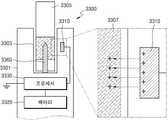
- 33Aillustrates a state before the aerosol-generating article is removed from the aerosol-generating device according to an embodiment.
- 33Billustrates a state after the aerosol-generating article is removed from the aerosol-generating device according to an embodiment.
- FIG. 34shows a block diagram of an aerosol generating device according to another embodiment.
- an aerosol-generating devicemay be a device that generates an aerosol using an aerosol-generating material to generate an inhalable aerosol directly into the user's lungs through the user's mouth.
- the aerosol generating devicemay be a holder.
- the term “puff”refers to a user's inhalation, and inhalation may refer to a situation in which the user's mouth or nose is drawn into the user's mouth, nasal cavity, or lungs.
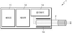
- FIG. 1 to 3are views illustrating examples in which an aerosol-generating article is inserted into an aerosol-generating device.
- the aerosol generating device 1includes a battery 11 , a control unit 12 , and a heater 13 . 2 and 3 , the aerosol generating device 1 further comprises a vaporizer 14 . In addition, a cigarette 2 may be inserted into the inner space of the aerosol generating device 1 .
- the aerosol generating device 1 shown in FIGS. 1 to 3shows components related to the present embodiment. Therefore, it can be understood by those of ordinary skill in the art related to this embodiment that other general-purpose components other than those shown in FIGS. 1 to 3 may be further included in the aerosol generating device 1 . .
- the heater 13is included in the aerosol generating device 1 in FIGS. 2 and 3 , if necessary, the heater 13 may be omitted.
- FIG. 1illustrates that the battery 11, the control unit 12, and the heater 13 are arranged in a line.
- FIG. 2the battery 11 , the control unit 12 , the vaporizer 14 , and the heater 13 are illustrated as being arranged in a line.
- FIG. 3shows that the vaporizer 14 and the heater 13 are arranged in parallel.
- the internal structure of the aerosol generating device 1is not limited to those shown in FIGS. 1 to 3 . In other words, depending on the design of the aerosol generating device 1 , the arrangement of the battery 11 , the control unit 12 , the heater 13 and the vaporizer 14 may be changed.
- the aerosol-generating device 1may actuate the heater 13 and/or the vaporizer 14 to generate an aerosol.
- the aerosol generated by the heater 13 and/or the vaporizer 14passes through the cigarette 2 and is delivered to the user.
- the battery 11supplies the power used to operate the aerosol generating device 1 .
- the battery 11may supply electric power so that the heater 13 or the vaporizer 14 can be heated, and may supply electric power required for the control unit 12 to operate.
- the battery 11may supply power required to operate a display, a sensor, a motor, etc. installed in the aerosol generating device 1 .
- the control unit 12controls the overall operation of the aerosol generating device 1 . Specifically, the control unit 12 controls the operation of the battery 11 , the heater 13 and the vaporizer 14 , as well as other components included in the aerosol generating device 1 . Also, the control unit 12 may determine whether the aerosol generating device 1 is in an operable state by checking the state of each of the components of the aerosol generating device 1 .
- the control unit 12includes at least one processor.
- the processormay be implemented as an array of a plurality of logic gates, or may be implemented as a combination of a general-purpose microprocessor and a memory in which a program executable in the microprocessor is stored.
- a general-purpose microprocessorand a memory in which a program executable in the microprocessor is stored.
- itcan be understood by those of ordinary skill in the art to which this embodiment pertains that it may be implemented in other types of hardware.
- the heater 13may be heated by electric power supplied from the battery 11 .
- the heater 13may be located external to the aerosol-generating article.
- the heated heater 13may raise the temperature of the aerosol-generating material in the aerosol-generating article.
- the heater 13may be an electrically resistive heater.
- the heater 13may include an electrically conductive track, and the heater 13 may be heated as current flows through the electrically conductive track.
- the heater 13is not limited to the above-described example, and may be applicable without limitation as long as it can be heated to a desired temperature.
- the desired temperaturemay be preset in the aerosol generating device 1 or may be set to a desired temperature by the user.
- the heater 13may be an induction heating type heater.
- the heater 13may include an electrically conductive coil for heating the aerosol-generating article in an induction heating manner, and the aerosol-generating article may include a susceptor capable of being heated by the induction heating heater.
- the heater 13may comprise a tubular heating element, a plate-shaped heating element, a needle-shaped heating element, or a rod-shaped heating element, depending on the shape of the heating element, inside or outside the aerosol-generating article 2 . It can be heated outside.
- a plurality of heaters 13may be disposed in the aerosol generating device 1 .
- the plurality of heaters 13may be disposed to be inserted into the interior of the aerosol-generating article 2 , or may be disposed on the outside of the aerosol-generating article 2 .
- some of the plurality of heaters 13may be disposed to be inserted inside the aerosol-generating article 2 , and the rest may be disposed outside the aerosol-generating article 2 .
- the shape of the heater 13is not limited to the shape shown in FIGS. 1 to 3 , and may be manufactured in various shapes.
- Vaporizer 14may heat the liquid composition to generate an aerosol, which may be passed through aerosol generating article 2 and delivered to a user.
- the aerosol generated by the vaporizer 14may travel along an airflow passage of the aerosol-generating device 1 , wherein the aerosol generated by the vaporizer 14 passes through the aerosol-generating article to a user It can be configured to be delivered to
- the vaporizer 14may include, but is not limited to, a liquid reservoir, a liquid delivery means and a heating element.
- the liquid reservoir, the liquid delivery means and the heating elementmay be included in the aerosol-generating device 1 as independent modules.
- the liquid reservoirmay store the liquid composition.
- the liquid compositionmay be a liquid comprising a tobacco-containing material comprising a volatile tobacco flavor component, or may be a liquid comprising a non-tobacco material.
- the liquid storage unitmay be manufactured to be detachably/attached from the vaporizer 14 , or may be manufactured integrally with the vaporizer 14 .
- the liquid compositionmay include water, a solvent, ethanol, a plant extract, a flavoring, flavoring agent, or a vitamin mixture.
- the fragrancemay include, but is not limited to, menthol, peppermint, spearmint oil, various fruit flavoring ingredients, and the like.
- Flavoring agentsmay include ingredients capable of providing a user with a variety of flavors or flavors.
- the vitamin mixturemay be a mixture of at least one of vitamin A, vitamin B, vitamin C, and vitamin E, but is not limited thereto.
- Liquid compositionsmay also include aerosol formers such as glycerin and propylene glycol.
- the liquid delivery meansmay deliver the liquid composition of the liquid reservoir to the heating element.
- the liquid delivery meansmay be, but is not limited to, a wick such as cotton fiber, ceramic fiber, glass fiber, or porous ceramic.
- the heating elementis an element for heating the liquid composition delivered by the liquid delivery means.
- the heating elementmay be, but is not limited to, a metal heating wire, a metal heating plate, a ceramic heater, or the like.
- the heating elementmay be composed of a conductive filament, such as a nichrome wire, and may be arranged to be wound around the liquid delivery means. The heating element may be heated by supplying an electrical current, and may transfer heat to the liquid composition in contact with the heating element, thereby heating the liquid composition. As a result, an aerosol may be generated.
- the vaporizer 14may be referred to as a cartomizer or an atomizer, but is not limited thereto.
- the aerosol generating device 1may further include general-purpose components in addition to the battery 11 , the controller 12 , the heater 13 , and the vaporizer 14 .
- the aerosol generating device 1may include a display capable of outputting visual information and/or a motor for outputting tactile information.
- the aerosol-generating device 1may include at least one sensor (a puff detection sensor, a temperature detection sensor, an aerosol-generating article insertion detection sensor, etc.).
- the aerosol generating device 1may be manufactured to have a structure in which external air may be introduced or internal gas may flow out even in a state in which the aerosol generating article 2 is inserted.
- the aerosol generating device 1may constitute a system together with a separate cradle.
- the cradlemay be used for charging the battery 11 of the aerosol generating device 1 .
- the heater 13may be heated in a state in which the cradle and the aerosol generating device 1 are coupled.
- the aerosol-generating article 2may be similar to a conventional combustible cigarette.
- the aerosol-generating article 2may be divided into a first part comprising an aerosol-generating material and a second part comprising a filter or the like.
- the second part of the aerosol-generating article 2may also contain an aerosol-generating material.
- an aerosol-generating material made in the form of granules or capsulesmay be inserted into the second part.
- the entire first partmay be inserted into the aerosol generating device 1 , and the second part may be exposed to the outside.
- only a part of the first partmay be inserted into the aerosol generating device 1, and the whole of the first part and a part of the second part may be inserted.
- the usermay inhale the aerosol while biting the second part with the mouth. At this time, the aerosol is generated by passing the outside air through the first part, and the generated aerosol passes through the second part and is delivered to the user's mouth.
- external airmay be introduced through at least one air passage formed in the aerosol generating device 1 .
- the opening and closing of the air passage and/or the size of the air passage formed in the aerosol generating device 1may be adjusted by the user. Accordingly, the amount of atomization, the feeling of smoking, and the like can be adjusted by the user.
- outside airmay be introduced into the interior of the aerosol-generating article 2 through at least one hole formed in the surface of the aerosol-generating article 2 .
- 4 and 5are diagrams illustrating examples of aerosol-generating articles.
- the aerosol-generating article 2comprises a tobacco rod 21 and a filter rod 22 .
- the first part 21 described above with reference to FIGS. 1 to 3includes a tobacco rod 21
- the second part 22includes a filter rod 22 .
- the filter rod 22is shown as a single segment, but is not limited thereto.
- the filter rod 22may be composed of a plurality of segments.
- the filter rod 22may include a segment that cools the aerosol and a segment that filters certain components contained within the aerosol.
- the filter rod 22may further include at least one segment performing other functions.
- the aerosol generating article 2may be wrapped by at least one wrapper 24 . At least one hole through which external air is introduced or internal gas flows may be formed in the wrapper 24 . As an example, the aerosol generating article 2 may be wrapped by one wrapper 24 . As another example, the aerosol generating article 2 may be wrapped by two or more wrappers 24 overlappingly.
- the tobacco rod 21may be packaged by the first wrapper 241
- the filter rod 22may be packaged by the wrappers 242 , 243 , and 244 .
- the entire aerosol-generating article 2can be repackaged by a single wrapper 245 . If the filter rod 22 is composed of a plurality of segments, each segment may be wrapped by wrappers 242 , 243 , 244 .
- the tobacco rod 21comprises an aerosol generating material.
- the aerosol generating materialmay include, but is not limited to, at least one of glycerin, propylene glycol, ethylene glycol, dipropylene glycol, diethylene glycol, triethylene glycol, tetraethylene glycol and oleyl alcohol.
- the tobacco rod 21may contain other additive substances such as flavoring agents, wetting agents and/or organic acids.
- a flavoring liquidsuch as menthol or a moisturizing agent can be added to the tobacco rod 21 by being sprayed onto the tobacco rod 21 .
- Tobacco rod 21may be manufactured in various ways.
- the tobacco rod 21may be manufactured as a sheet or as a strand.
- the tobacco rod 21may be made of cut filler from which the tobacco sheet is chopped.
- the tobacco rod 21may be surrounded by a heat-conducting material.
- the heat-conducting materialmay be, but is not limited to, a metal foil such as aluminum foil.
- the heat-conducting material surrounding the tobacco rod 21may improve the thermal conductivity applied to the tobacco rod by evenly distributing the heat transferred to the tobacco rod 21, thereby improving the tobacco taste.
- the heat-conducting material surrounding the tobacco rod 21may function as a susceptor heated by an induction heater. At this time, although not shown in the drawings, the tobacco rod 21 may further include an additional susceptor in addition to the heat-conducting material surrounding the outside.
- the filter rod 22may be a cellulose acetate filter.
- the shape of the filter rod 22is not limited.
- the filter rod 22may be a cylindrical rod, or a tubular rod including a hollow therein.
- the filter rod 22may be a recess type rod. If the filter rod 22 is composed of a plurality of segments, at least one of the plurality of segments may be manufactured in a different shape.
- the filter rod 22may include at least one capsule 23 .
- the capsule 23may perform a function of generating flavor, or may perform a function of generating an aerosol.
- the capsule 23may have a structure in which a liquid containing a fragrance is wrapped with a film.
- the capsule 23may have a spherical or cylindrical shape, but is not limited thereto.
- the aerosol-generating article 3may further comprise a shear plug 33 .
- the front plug 33may be located on one side of the tobacco rod 31 opposite to the filter rod 32 .
- the shear plug 33can prevent the tobacco rod 31 from escaping to the outside, and the aerosol liquefied from the tobacco rod 31 during smoking flows into the aerosol generating device ( 1 in FIGS. 1 to 3 ). can be prevented
- the filter rod 32may include a first segment 321 and a second segment 322 .
- the first segment 321may correspond to the first segment of the filter rod 22 of FIG. 4
- the second segment 322may correspond to the third segment of the filter rod 22 of FIG. 4 .
- the diameter and overall length of the aerosol-generating article 3may correspond to the diameter and overall length of the aerosol-generating article 2 of FIG. 4 .
- the length of the shear plug 33is about 7 mm
- the length of the tobacco rod 31is about 15 mm
- the length of the first segment 321is about 12 mm
- the length of the second segment 322is about 14 mm.
- the present inventionis not limited thereto.
- the aerosol-generating article 3may be wrapped by at least one wrapper 35 . At least one hole through which external air flows or internal gas flows may be formed in the wrapper 35 .
- the shear plug 33is wrapped by the first wrapper 351
- the tobacco rod 31is wrapped by the second wrapper 352
- the first segment ( 353 )is wrapped by the third wrapper 353 .
- 321may be wrapped
- the second segment 322may be wrapped by the fourth wrapper 354 .
- the entire aerosol-generating article 3may be repackaged by the fifth wrapper 355 .
- At least one perforation 36may be formed in the fifth wrapper 355 .
- the perforations 36may be formed in the area surrounding the tobacco rod 31, but are not limited thereto.
- the perforation 36may serve to transfer heat formed by the heater 13 shown in FIGS. 2 and 3 to the inside of the tobacco rod 31 .
- the second segment 322may include at least one capsule 34 .
- the capsule 34may perform a function of generating flavor, or may perform a function of generating an aerosol.
- the capsule 34may have a structure in which a liquid containing fragrance is wrapped with a film.
- the capsule 34may have a spherical or cylindrical shape, but is not limited thereto.
- 6Ashows a schematic diagram for explaining a relationship between an electrode and an aerosol-generating article according to an embodiment.
- the aerosol generating device 600may include an electrode 620 and a processor 640 .
- the processor 640is based on the charging time or the discharging time of the electrode 620, the function of detecting whether the insertion / removal of the aerosol-generating article 605, the function of detecting the user's puff and the amount of aerosol generated Accordingly, it is possible to perform a function of controlling the power supplied to the heater.
- the processor 640may measure the charging time of the electrode 620 by applying a specific voltage to the electrode 620 .
- the processor 640may perform various functions based on the measured charging time of the electrode 620 or a change in the charging time.
- the processor 640may measure the discharge time of the electrode 620 as the electrode 620 is naturally discharged. That is, when the charging voltage of the electrode 620 is the same as the applied voltage, the processor 640 may measure the discharge time of the electrode 620 , and the measured discharge time or change in the discharge time of the electrode 620 . Based on the above, the various functions may be performed.
- the electrode 620when the aerosol-generating article 605 is inserted into a portion (eg, a receptacle) of the aerosol-generating device 600 , the electrode 620 is spaced apart from the inserted aerosol-generating article 605 by a predetermined distance. can be placed.
- the predetermined distancemay mean a distance in which a change in charging time or discharging time of the electrode 620 generated by the aerosol-generating article 605 can be sensed.
- the electrode 620may be positioned to correspond to at least one region of the inserted aerosol-generating article 605 .
- the electrode 620may be positioned to correspond to at least one region in which the aerosol-generating material of the aerosol-generating article 605 is disposed.
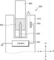
- Figure 6bshows an exemplary view of the position of the electrode of the aerosol generating device according to an embodiment.
- the aerosol generating device 600may include a housing 610 , an electrode 620 , and a heater 650 .
- the aerosol-generating device 600may include a receptacle into which the aerosol-generating article 605 may be inserted.
- the housing 610may correspond to a cylinder shape including an outer circumferential surface and an inner circumferential surface.
- the accommodating partmay mean a space surrounded by the inner circumferential surface of the housing 610 or a region corresponding to the inner circumferential surface of the housing 610 .
- the shape of the housing 610is not limited thereto, and may be variously changed according to the design of the manufacturer.
- the electrode 620may be disposed to be spaced apart from the inner circumferential surface of the housing 610 in the direction of the outer circumferential surface of the housing 610 .
- the housing 610may extend in a first direction (eg, a +y direction), and the electrodes 620 may be disposed to be spaced apart from each other in a direction perpendicular to the first direction (eg, a +x direction).
- the electrode 620may be buried between the inner circumferential surface and the outer circumferential surface of the housing 610 .
- the electrode 620As the electrode 620 is disposed inside the housing 610 , noise of a data measurement result measured by the processor through the electrode 620 may be reduced. For example, if the electrode 620 is disposed to be exposed to the outside and comes into contact with the aerosol-generating article 605, the electrode 620 may be affected by data measurement due to external substances (eg, tobacco leaves, dust, etc.). have. Contrary to this, since the electrode 620 according to the present disclosure is disposed to be buried inside the housing 610 or not exposed to the outside by a separate protective layer, contamination by external substances does not occur, so noise on data measurement has a reducing effect.
- external substanceseg, tobacco leaves, dust, etc.
- the electrode 620may be disposed to correspond to at least one region where the aerosol generating material 630 is disposed.
- the position of the electrode 620may correspond to a region where the aerosol-generating material 630 is disposed as the aerosol-generating article 605 is fully inserted into the receptacle of the aerosol-generating device 600 .
- the heater 650may correspond to an internal heating type heater.
- the type of the heater 650is not limited thereto, and the shape of the heater in various embodiments according to the present disclosure will be described later with reference to FIGS. 11A to 13B .
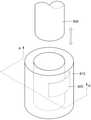
- 7Ashows a perspective view of a housing of an aerosol-generating device according to an embodiment.
- 7Bis a cross-sectional view of the housing of the aerosol generating device according to an embodiment cut in the A-A' direction.
- 7A and 7Bmay correspond to a specific example of the electrode 620 included in the aerosol generating device 600 of FIG. 6 .
- the electrode 720may be in the form of a plate having no curvature. In an embodiment, the electrode 720 may be disposed to be spaced apart from the receiving part 715 by a predetermined distance. At this time, since the electrode 720 is in the form of a plate having no curvature, the central portion of the electrode 720 is spaced apart from the receiving portion 715 by x, and the distal portion of the electrode 720 is separated from the receiving portion 715 . can be further apart than x. In order to minimize the difference between the distance between the receptacle 715 and the central portion of the electrode 720 and the distance between the receptacle 715 and the distal portion of the electrode 720 , the width of the electrode 720 is substantially can be formed narrowly.
- 8Ashows a perspective view of a housing of an aerosol-generating device according to another embodiment
- 8Bis a cross-sectional view of the housing of the aerosol generating device according to another embodiment, taken in the A-A' direction
- 9Ashows a perspective view of a housing of an aerosol-generating device according to another embodiment
- FIG. 9Bis a cross-sectional view showing a housing of an aerosol generating device according to another embodiment, cut in the A-A' direction.
- 8A, 8B, 9A and 9Bmay correspond to a specific example of the electrode 620 included in the aerosol generating device 600 of FIG. 6 .
- the electrodes 820 and 920may be in the form of a plate having a specific curvature.
- the electrodes 820 and 920may have a curvature smaller than the curvature of the inner peripheral surfaces of the housings 810 and 910 and greater than the curvature of the outer peripheral surfaces of the housings 810 and 910 .
- all parts (eg, the central part, the distal part, etc.) of the electrodes 820 and 920are spaced apart from the receiving parts 815 and 915 by a certain distance. can be placed.
- the electrodes 820 and 920may be spaced apart from the accommodating parts 815 and 915 by a predetermined distance x to surround at least a portion of the accommodating parts 815 and 915 .
- the electrode 820may be disposed to surround only a region corresponding to a portion (eg, 25%) of the circumference of the accommodating portion 815 .
- the electrode 920may be disposed to surround a region corresponding to a portion (eg, 90%) of the circumference of the accommodating portion 915 .
- the region surrounded by the electrode 620is not limited thereto.
- FIG 10shows an exemplary view of the position of the electrode of the aerosol generating device according to another embodiment.
- the aerosol generating device 1000may include a housing 1010 and an electrode 1020 .
- the aerosol-generating device 1000may include a receptacle into which the aerosol-generating article 1005 may be inserted.
- the housing 1010may correspond to a cylinder shape including an outer circumferential surface and an inner circumferential surface.
- the shape of the housing 1010is not limited thereto, and may be variously changed according to the design of the manufacturer.
- the electrode 1020may be disposed to contact a region of the inner peripheral surface of the housing 1010 .
- a separate protective layer 1040may be disposed on the inner circumferential surface of the housing 1010 .
- the protective layer 1040may be formed to have a predetermined thickness x, and the electrode 1020 may be disposed to be spaced apart from the inner circumferential surface of the protective layer 1040 by a predetermined distance x.
- the protective layer 1040may be formed of a material, color, or pattern different from that of the housing 1010 .
- the protective layer 1040may mean a plating layer, an oxide layer, etc. formed so as not to react with the aerosol-generating article 1005 or an aerosol generated by the aerosol-generating article 1005 .
- the electrode 1020may be disposed to correspond to at least one region where the aerosol generating material 1030 is disposed.
- the position of the electrode 1020may correspond to a region where the aerosol-generating material 1030 is disposed as the aerosol-generating article 1005 is fully inserted into the receptacle of the aerosol-generating device 1000 .
- 11Ashows an exemplary view of a position of an electrode of an aerosol generating device according to another embodiment.
- 11Bshows an exemplary view of a position of an electrode with respect to a heater according to another embodiment.
- 11A and 11Bmay correspond to a specific example of the heater 650 included in the aerosol generating device 600 of FIG. 6 .
- the aerosol generating device 1100may include a housing 1110 , an electrode 1120 , and a heater 1150 .
- the heater 1150may correspond to a film heater including patterns arranged at regular intervals.
- the heater 1150may include a heating pattern 1140 and an electrode 1120 .
- the heating pattern 1140may be printed on the heater 1150 in the form of a film (eg, a polyimide film).
- the electrode 1120may be attached to at least a portion of the heater 1150 .
- the electrode 1120may be disposed in a region that does not overlap the heating pattern 1140 of the heater 1150 .
- the electrode 1120may be disposed in at least one of region A (eg, an outer portion of the heating pattern) and region B (eg, an inner portion of the heating pattern).
- 12Ashows an exemplary view of a position of an electrode of an aerosol generating device according to another embodiment.
- 12Bshows an exemplary view of a position of an electrode of an aerosol generating device according to another embodiment.
- 12A and 12Bmay correspond to a specific example of the heater 650 included in the aerosol generating device 600 of FIG. 6 .
- the aerosol generating device 1200may include a housing 1210 , an electrode 1220 , and a heater.
- the heatermay include an internal heating type heater 1230 and an induction coil 1240 .
- the induction coil 1240may induce a variable magnetic field to heat the internal heating type heater 1230 of the aerosol generating device 1200 .
- the internal heating type heater 1230may correspond to an example of the susceptor.
- the heatermay include only the induction coil 1240 .
- the induction coil 1240can induce a variable magnetic field to heat the susceptor 1250 included in the medium region of the aerosol-generating article 1205 .
- the electrode 1220may be disposed between the inner circumferential surface of the housing 1210 and the induction coil 1240 .
- the electrode 1220may be formed so as not to affect the variable magnetic field generated from the induction coil 1240 .
- the width of the electrode 1220may be formed to be substantially narrow.
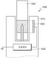
- 13Ashows an exemplary view of a position of an electrode of an aerosol generating device according to another embodiment.
- 13Bshows an exemplary view of a position of an electrode of an aerosol generating device according to another embodiment.
- 13A and 13Bmay correspond to a specific example of the electrode 620 and the heater 650 included in the aerosol generating device 600 of FIG. 6 .
- the aerosol generating device 1300may include a housing 1310 and a heater.
- the heatermay include an internal heating type heater 1330 and an induction coil 1340 .
- the induction coil 1340may induce a variable magnetic field to heat the internal heating type heater 1330 of the aerosol generating device 1300 .
- the heatermay include only the induction coil 1340 .
- the induction coil 1340may induce a variable magnetic field to heat the susceptor 1350 included in the medium region of the aerosol-generating article 1305 .
- the electrode(eg, the electrode 620 of FIG. 6 ) may be integrally formed with the induction coil 1340 . That is, the induction coil 1340 may perform a sensing function of an electrode while heating a heating object (eg, an internal heating type heater or a susceptor) by inducing a variable magnetic field. A detailed description of the sensing function of the electrode will be described later with reference to FIG. 15 .
- a heating objecteg, an internal heating type heater or a susceptor
- Figure 14shows a circuit diagram for the electrode in Figures 13a and 13b;
- a processormay include an induction heating controller 1400 and a sensor controller 1410 .
- the induction heating controller 1400may heat a heating object (eg, an internal heating type heater 1330 and a susceptor 1350 ) by inducing a variable magnetic field through an induction coil.
- the sensor controller 1410may apply power to the induction coil, detect a change in the charging time of the induction coil, and perform a sensing operation.
- the induction coilmay be selectively controlled by the induction heating controller 1400 or the sensor controller 1410 .
- the induction coilmay perform a heating operation through the induction heating controller 1400 .
- the connection between the sensor controller 1410 and the induction coilmay be disconnected.
- the induction heating controller 1400performs a heating operation by inducing a variable magnetic field through an induction coil
- the switch A and the switch Care in an on state
- the switch B and the switch Dare in an off state
- the induction coilmay receive power through the sensor controller 1410 and perform a sensing operation.
- the sensing operationmay include at least one of: sensing whether an aerosol-generating article (eg, the aerosol-generating article 605 of FIG. 6A ) is inserted/removed, sensing an atomization amount generated by the aerosol-generating article 605, and sensing a puff of the user. may contain one.
- the connection between the induction heating controller 1400 and the induction coilmay be cut off.
- the switch A and the switch Cmay be switched to an off state, and the switch B and the switch D may be switched to an on state.
- the induction coilperforms a sensing operation through the sensor controller 1410
- one end of the circuitmay be opened to serve as a ground (GND) terminal.
- GNDground
- the switch Cis switched to the off state, one end of the induction coil is opened to serve as a ground terminal.
- the sensor controller 1410 and the induction coilare connected by two lines, but is not limited thereto. In another embodiment, the sensor controller 1410 and the induction coil may be connected with only one line including the switch B.
- FIG. 15shows a block diagram of an aerosol generating device according to an embodiment.
- the aerosol generating device 1500may include an electrode 1510 , a battery 1520 , a processor 1530 , and a heater 1540 .
- the electrode 1510may have a change in the amount of charge when a change according to the aerosol-generating article occurs.
- changes with an aerosol-generating articlemay include insertion, removal of an aerosol-generating article, generating an aerosol according to the aerosol-generating article, and removing the aerosol by a puff of a user, and the like.
- the electrode 1510when the aerosol-generating article is inserted into the aerosol-generating device 1500 and disposed in proximity to the electrode 1510, the electrode 1510 according to the permittivity ( ⁇ ) of the component included in the aerosol-generating article.
- the amount of chargecan vary.
- the permittivityis a characteristic value indicating the electrical characteristics of the insulator, and may mean the size of polarization created with respect to an external electric field. At this time, even when the inserted aerosol-generating article is removed, the charge amount of the electrode 1510 may change.
- the aerosol-generating articleis a cigarette
- the cigarettecontains a packaging material having an amount of moisture or moisture (eg, an outer wrapper, an inner wrapper, etc.) and a solid smokeable material (eg, tobacco leaves, granules) included in the medium. form of tobacco substances, etc.).
- a packaging materialhaving an amount of moisture or moisture (eg, an outer wrapper, an inner wrapper, etc.) and a solid smokeable material (eg, tobacco leaves, granules) included in the medium. form of tobacco substances, etc.).
- H2Opermittivity of water
- the electrode 1510may be affected when the cartridge is inserted as it contains a liquid having a high permittivity value.
- the charge amount of the electrode 1510may be reduced. In one embodiment, as the aerosol-generating article is removed from the aerosol-generating device 1500 as it moves away from the electrode 1510 , the amount of charge on the electrode 1510 may increase.
- the processor 1530may determine whether to insert or remove the aerosol-generating article by using the dielectric constant of a component included in the aerosol-generating article. Through this, the material of the aerosol-generating article can be variously changed.
- the conventional aerosol-generating devicedetermines whether the aerosol-generating article is inserted through the wrapping paper of the aerosol-generating article or the aluminum foil included in the wrapping paper. However, even if the aerosol-generating article does not include aluminum foil, the aerosol-generating device according to the present disclosure can determine whether the aerosol-generating article is inserted or removed, so the manufacturer can variously change the material of the wrapping paper.
- the amount of electric charge of the electrode 1510may change according to the dielectric constant of the aerosol.
- an aerosol generating articlewhen heated by the heater 1540, an aerosol with a constant moisture content may be generated.
- the dielectric constant of the aerosolis about 80 times greater than that of air, the electrode 1510 may be affected when the aerosol is generated.
- the amount of charge on the electrode 1510may decrease. In one embodiment, when the aerosol generated as the aerosol-generating article is heated is removed by the user's puff, the amount of charge of the electrode 1510 may increase.
- the processor 1530may determine the amount of aerosol generated and whether the user puffs by using the dielectric constant of the aerosol generated as the aerosol-generating article is heated. Through this, the aerosol generating device 1500 may provide a uniform atomization amount, and may detect the user's puff without a separate sensor module (eg, a puff detection sensor).
- a separate sensor moduleeg, a puff detection sensor
- the battery 1520may supply power required for the aerosol generating device 1500 to operate.
- the battery 1520may supply power to the processor 1530 to detect a change in the amount of charge in the electrode 1510 .
- the battery 1520has other hardware components included in the aerosol generating device 1500, for example, various sensors (not shown), a user interface (not shown), and power required for the operation of a memory (not shown). can supply
- the battery 1520may be a rechargeable battery or a disposable battery.
- the battery 1520may be a lithium polymer (LiPoly) battery, but is not limited thereto.
- the processor 1530may control the overall operation of the aerosol generating device 1500 .
- the processor 1530may control the operation of the battery 1520 as well as other components included in the aerosol generating device 1500 .
- the processor 1530may determine whether the aerosol generating device 1500 is in an operable state by checking the state of each of the components of the aerosol generating device 1500 .
- the processor 1530may detect a change according to the aerosol-generating article based on the voltage of the electrode 1510 .
- the processor 1530may determine a change in the charging time of the electrode 1510 based on the output voltage Vout and the input voltage Vin for the electrode 1510 .
- the processor 1530may detect a change with the aerosol-generating article based on a change in the charging time of the electrode 1510 .
- a method for the processor 1530 to check the voltage of the electrode 1510will be described later with reference to FIGS. 17 and 18 .
- FIGS. 16A and 16Bare diagrams illustrating an example of a method for an electrode of an aerosol-generating device to determine a type of an aerosol-generating article according to an embodiment.
- the aerosol generating device 1600 of FIGS. 16A and 16Bmay correspond to the aerosol generating device 1500 of FIG. 15 .
- the first aerosol-generating article 1650may have a larger area comprising tobacco material than the second aerosol-generating article 1660 .
- the tobacco materialmay include at least one of a solid phase and a liquid phase formed in the form of granules, capsules, and the like.
- the processor 1630may determine the type of the aerosol-generating article through the electrode 1620 .
- the first aerosol-generating article 1650may comprise more moisture according to the tobacco material than the second aerosol-generating article 1660 .
- the processor 1630may determine that the first aerosol-generating article 1650 is inserted if the charge amount of the electrode 1620 is further reduced.
- the processor 1630may store the amount of electric charge of the electrode 1620 reduced for each type of aerosol-generating article in a memory (not shown).
- the second aerosol-generating article 1660is the first aerosol-generating article according to the composition ratio of the tobacco material included in the first aerosol-generating article 1650 and the second aerosol-generating article 1660 . It may contain more moisture depending on the tobacco material than (1650).
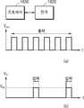
- 17is a graph for explaining a method in which a processor detects a change in a charging time of an electrode according to an embodiment.
- a processor(eg, the processor 1630 of FIGS. 16A and 16B ) may be connected to an electrode (eg, the electrode 1620 of FIGS. 16A and 16B ) by one line.
- the processor 1630may apply an output voltage to the electrode 1620 at a predetermined period to charge the electrode 1620 .
- the output voltagemay be adjusted and applied in a pulse width modulation (PWM) method.
- PWMpulse width modulation
- the processor 1630may apply an output voltage to the electrode 1620 every 50 ms to charge the electrode 1620 .
- the processor 1630may sense an input voltage input from the electrode 1620 after applying the output voltage to the electrode 1620 a preset number of times (eg, 2).
- the voltage value of the output voltagemay correspond to a range of about 2.8V to 3.3V.
- the voltage value of the output voltagemay correspond to about 5V.
- the preset number of times when the processor 1630 applies the output voltagemay be variously changed according to the design of the manufacturer.
- the processor 1630may determine whether an event has occurred by detecting a change in the input voltage input from the electrode 1620 . For example, when the input voltage input from the electrode 1620 is sensed to be lower than the reference voltage Vref as shown in the graph (b), the processor 1630 may detect 1700 occurrence of the event. For example, when the input voltage input from the electrode 1620 is initially sensed to be lower than the reference voltage Vref, the processor 1630 may determine that an event in which the aerosol-generating article is inserted has occurred.
- the processor 1630applies the output voltage to the electrode 1620 at a predetermined period, so that the input voltage is adjusted to the reference voltage Vref. can be reached
- FIG. 18is a graph illustrating a method in which a processor detects a change in a charging time of an electrode according to another exemplary embodiment.
- the processor 1630 and the electrode 1620may be connected by at least two or more lines.
- the at least two or more linesapply an input voltage to the processor 1630 to transmit a line to which the processor 1630 applies an output voltage to charge the electrode 1620 and a state of charge of the electrode 1620 . It may contain a line that says
- the processor 1630may apply an output voltage to the electrode 1620 at a predetermined period as shown in graph (a).
- the output voltagemay be adjusted and applied in a pulse width modulation (PWM) method.
- PWMpulse width modulation
- the processor 1630may apply an output voltage to the electrode 1620 every 50 ms to charge the electrode 1620 .
- the processor 1630may sense an input voltage input from the electrode 1620 while simultaneously applying an output voltage to the electrode 1620 . For example, in checking the state of charge of the electrode 1620 , the processor 1630 may sense the input voltage without stopping the output of the output voltage for charging the electrode 1620 .
- FIG. 18is only an example, and even if the processor 1630 and the electrode 1620 are connected by two or more lines, the processor 1630 detects the input voltage input from the electrode 1620, and outputs the output voltage. may be stopped.
- 19Ais a graph illustrating a charging time of an electrode of an aerosol generating device according to an embodiment.
- an aerosol-generating articleeg, the aerosol-generating article 605 of FIG. 6
- an aerosol-generating deviceeg, the aerosol-generating device 600 of FIG. 6
- puff by a useris performed.
- the change in charging time of an electrodeeg, electrode 620 in FIG. 6
- the processormay detect the insertion of the aerosol-generating article 605 based on the charging time of the electrode 620 in (i) section. In an embodiment, the processor 1530 detects and counts the user's puff based on the charging time of the electrode 620 in section (ii), and calculates the heating temperature of the heater (eg, the heater 1540 of FIG. 15 ). can be controlled In an embodiment, the processor 1530 may detect the removal of the aerosol-generating article 605 based on the charging time of the electrode 620 in section (iii) and control the cleaning operation of the heater 1540 . . A detailed operation of the processor for each section will be described later with reference to FIGS. 20 to 33B .
- Fig. 19bshows a graph of discharge time of the electrode in Fig. 19a.
- an aerosol-generating articleeg, the aerosol-generating article 605 of FIG. 6
- an aerosol-generating deviceeg, the aerosol-generating device 600 of FIG. 6
- puff by a useris performed.
- the change in the discharge time of the electrodeeg, the electrode 620 of FIG. 6
- the processormay detect the insertion of the aerosol-generating article 605 based on the discharge time of the electrode 620 in (i) section. In an embodiment, the processor 1530 detects and counts the user's puff based on the discharge time of the electrode 620 in section (ii), and calculates the heating temperature of the heater (eg, the heater 1540 of FIG. 15 ). can be controlled In an embodiment, the processor 1530 may detect the removal of the aerosol-generating article 605 based on the discharge time of the electrode 620 in the section (iii) and control the cleaning operation of the heater 1540 . .
- the graph of the discharge time of the electrode in FIG. 19Bis shown in an inverted form with respect to the graph of the charging time of the electrode in FIG. 19A, but is not limited thereto.
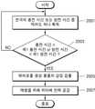
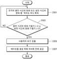
- FIG. 20depicts a flow diagram in which an aerosol-generating device detects insertion of an aerosol-generating article according to an embodiment.
- the flowchart of FIG. 20may correspond to the operation of the processor in section (i) of FIG. 19 .
- the processormay acquire at least one of a charging time or a discharging time of an electrode (eg, the electrode 1510 of FIG. 15 ) in operation 2001 .
- the processor 1530may acquire the charging time of the electrode 1510 based on an input voltage input from the electrode 1510 (eg, the input voltage in FIGS. 17 and 18 ).
- the charging time of the electrode 1510may mean a time required for the charging voltage of the electrode 1510 to reach a predetermined reference voltage (eg, the reference voltage Vref in FIGS. 17 and 18 ). have.
- the processor 1530may obtain the discharge time of the electrode 1510 based on an input voltage input from the electrode 1510 .
- the discharge time of the electrode 1510may mean a time required for the charging voltage of the electrode 1510 to reach 0V.
- the processor 1530may determine whether the charging time of the electrode is longer than the specified first charging time or whether the discharging time of the electrode is shorter than the specified first discharging time.
- the specified first charging time and the specified first discharging timeare the charging time and discharging required for the charging voltage of the electrode 1510 having a reduced amount of charge to reach the predetermined reference voltage Vref as the aerosol-generating article is inserted. Each can mean time.
- the processor 1530may detect the insertion of the aerosol-generating article in operation 2005 . have. According to an embodiment, when the charging time of the electrode is shorter than the specified first charging time or the discharging time of the electrode is longer than the specified first discharging time, the processor 1530 may return to operation 2001 .
- the processor 1530may supply power to the heater 1540 to preheat the heater (eg, the heater 1540 of FIG. 15 ) in operation 2007 .
- the processor 1530may power the heater 1540 to perform an auto-start function of the aerosol-generating device (eg, the aerosol-generating device 1500 of FIG. 15 ).
- the heater 1540may be controlled to have any one of a range of a preheating temperature corresponding to about 220°C to 230°C, about 290°C to 300°C, and about 330°C to 340°C.
- the range of the preheating temperatureis exemplary, and the range of the preheating temperature may be variously changed according to the design of the manufacturer.
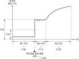
- 21is a graph illustrating a charging time of an electrode that changes as an aerosol-generating article is inserted into an aerosol-generating device according to an embodiment.
- the time interval for determining whether to insert the aerosol-generating article into the aerosol-generating deviceis a first interval 2100 , a second interval 2110 and It may be divided into a third section 2120 .
- the first section 2100may correspond to a section waiting before the aerosol-generating article is inserted.
- the second section 2110may correspond to a section in which the aerosol-generating article is prepared for preheating immediately after the aerosol-generating article is inserted.
- the third section 2120may correspond to a section in which the aerosol-generating article is preheated.
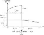
- the charging time required to charge the electrode (eg, the electrode 1510 of FIG. 15 ) in the first section 2100may be substantially constant. Since the electrode 1510 may be continuously discharged even if it does not include a separate discharging circuit, a constant charging time may be required to charge the amount of electric charge lost as the electrode 1510 is discharged. Accordingly, the processor of the aerosol generating device (eg, the processor 1530 of FIG. 15 ) may continuously apply a constant voltage to the electrode 1510 .
- the charging time of the electrodemay increase at the time point 2130 at which the aerosol-generating article is inserted. In this case, the charging time of the electrode may increase substantially rapidly. In one embodiment, when the charging time 2150 of the electrode 1610 is longer than the specified first charging time 2140 , the processor 1530 determines that the aerosol-generating article has been inserted, and a heater (eg, FIG. 15 ) of the heater 1540) may be controlled to preheat.
- a heatereg, FIG. 15
- the charging time of the electrode 1510may vary only within a specific range. According to an embodiment, while the aerosol-generating article is preheated in the third section 2120 , the charging time of the electrode 1510 may gradually increase.
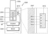
- 22Aillustrates a state before the aerosol-generating article is inserted into the aerosol-generating device according to an embodiment.
- 22Billustrates a state after the aerosol-generating article is inserted into the aerosol-generating device according to an embodiment.
- the aerosol generating device 2200may include a housing 2201 , an electrode 2210 , a battery 2220 , a processor 2230 , and a heater 2260 .
- the electrode 2210 of FIG. 22Amay include (+) charges equal to the first charge amount. Thereafter, when the aerosol-generating article 2205 is inserted against the receiving portion 2203 corresponding to the inner circumferential surface of the housing 2201 , the electrode 2210 of FIG. 22B is a component included in the aerosol-generating article 2205 . (eg, tobacco material 2207, external wrapper, etc.) It is possible to lose some of the positive charge by moisture. Accordingly, the electrode 2210 of FIG. 22B may include a (+) charge corresponding to a second charge amount less than the first charge amount.
- the charging time of the electrode 2210may increase.
- the processor 2230may detect an increase in the charging time of the electrode 2210 of FIG. 22B based on an input voltage input from the electrode 2210 .
- the processor 2230may determine that the aerosol-generating article 2205 is inserted when detecting that the charging time of the electrode 2210 is increased. In another embodiment, the processor 2230 determines that the charging voltage of the electrode 2210 decreases based on the increase in the charging time of the electrode 2210 , and the aerosol-generating article 2205 based on the decreased charging voltage It may be judged that this has been inserted.
- the processor 2230may receive power from the battery 2220 to apply power to the heater 2260 .
- the heater 2260may be an internal heating type heater.
- the heater 2260is not limited thereto, and may include at least one of an external heating type heater, an induction coil, and a susceptor.
- FIG. 23is a flowchart illustrating an aerosol generating device detecting a user's puff according to an embodiment.
- the flowchart of FIG. 23may correspond to the first operation of the processor in section (ii) of FIG. 19 .
- the processorobtains at least one of a change in charging time or a change in discharging time of an electrode (eg, electrode 1510 in FIG. 15 ) in operation 2301 .
- the processor 1530may detect a change in the amount of aerosol generated by the heater (eg, the heater 1540 of FIG. 15 ) based on a change in the charging time or the change in the discharging time of the electrode.
- the processor 1530may obtain a change in the charging time of the electrode 1510 based on an input voltage input from the electrode 1510 (eg, the input voltage in FIGS. 17 and 18 ). If the charging time for the electrode 1510 is reduced for a certain period of time, the processor 1530 may determine that the aerosol generated by the heater 1540 has been removed.
- the processor 1530may determine whether the gradient of change in the charging time of the electrode 1510 is a negative value or the gradient of change in the discharge time of the electrode 1510 is a positive value. . For example, when the gradient of change in the charging time of the electrode 1510 is a negative value or the gradient of change in the discharge time of the electrode 1510 is a positive value for a certain period of time, the processor 1530 is configured by the heater 1540. It may be determined that the generated aerosol is reduced by the user's puff.
- the processor 1530controls the user's puff in operation 2305. can be detected.
- the processor 1530may return to operation 2301 .
- the processor 1530may supply power to the heater 1540 to generate an aerosol in operation 2307 .
- the processor 1530may supply a predetermined power to the heater 1540 to generate an aerosol reduced by the user's puff.
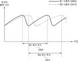
- FIG. 24is a graph illustrating a charging time of an electrode that changes as a user's puff is detected in the aerosol generating device according to an embodiment.
- the processormay acquire data on whether the user puffs by monitoring the charging time of the electrode (eg, the electrode 1510 of FIG. 15 ).
- the processor 1530may detect the user's puff based on a change in the charging time of the electrode 1510 .
- the processor 1530may detect the user's first puff. For example, when the processor 1530 detects that the change slope of the charging time of the electrode 1510 is changed from 0 to a negative value, the detection time is determined as the time point 2400 when the user's first puff is started. can When the processor 1530 detects that the change slope of the charging time of the electrode 1510 is changed from a negative value to 0, the processor 1530 may determine the detection time as a time point 2410 at which the user's first puff ends. As another example, when the gradient of change in the charging time of the electrode 1510 is maintained as a negative value for a predetermined time, the processor 1530 may detect the predetermined time as the user's first puff period.
- the processor 1530may detect the user's first puff. For example, when the designated change amount is 0.5 seconds and the change amount 2405 of the charging time of the electrode 1510 is 0.8 seconds, the processor 1530 may determine that the user's puff has occurred. However, the processor 1530 may detect not only the charging time but also the change in the charging voltage. That is, when the charging voltage of the electrode 1510 increases by more than a specified change amount, the processor 1530 may detect the user's first puff.
- the charging time of the electrode 1510may gradually increase from a time point 2410 at which the first puff ends to a time point 2420 at which the second puff starts. For example, when the user's first puff is finished, an aerosol may be generated from the aerosol-generating article until the next puff is started, and the capacitance of the electrode 1510 may change due to the generated aerosol. As the capacitance of the electrode 1510 changes, the charging time of the electrode 1510 gradually increases from the time point 2410 at which the first puff ends to the time point 2420 at which the second puff starts, and the electrode 1510 increases. ) may have a positive slope of change in charging time.
- the processor 1530may detect the user's second puff. For example, if it is detected that the change slope of the charging time of the electrode 1510 is changed from 0 to a negative value after the time point 2410 at which the first puff ends, the detection time point is set as the time point at which the user's second puff is started. It may be determined as a viewpoint 2420 . When the processor 1530 detects that the change slope of the charging time of the electrode 1510 is changed from a negative value to 0, the processor 1530 may determine the detection time point as a time point 2430 at which the user's second puff ends. As another example, when the gradient of change in the charging time of the electrode 1510 is maintained at a negative value for a predetermined time, the processor 1530 may detect the predetermined time as the user's second puff period.
- 25Aillustrates a state before the user's puff is detected in the aerosol generating device according to an embodiment.
- 25Billustrates a state after the user's puff is detected in the aerosol generating device according to an embodiment.
- the aerosol generating device 2500may include a housing 2501 , an electrode 2510 , a battery 2520 , a processor 2530 , and a heater 2560 .
- the electrode 2510 of FIG. 25Amay lose some of the (+) charge by moisture in a component (eg, tobacco material 2507 ) included in the aerosol-generating article 2505 .
- a componenteg, tobacco material 2507
- the electrode 2510 of FIG. 25Bmay contain a (+) charge equal to a second charge amount greater than the first charge amount.
- the charging time of the electrode 2510may decrease.
- the processor 2530may detect a decrease in the charging time of the electrode 2510 of FIG. 25B based on an input voltage input from the electrode 2510 .
- the processor 2530when the processor 2530 detects that the charging time of the electrode 2510 is reduced, it may be determined that the user's puff 2550 has occurred. In another embodiment, the processor 2530 determines that the charging voltage of the electrode 2510 increases based on the decrease in the charging time of the electrode, and determines that the user's puff 2550 has occurred based on the increased charging voltage. may judge.
- the processor 2530may count the number of puffs upon detecting the user's puffs 2550 . At this time, when the counted number of puffs exceeds the preset maximum number of puffs for the aerosol-generating article 2505 , the processor 2530 may limit the power supply to the heater 2560 . For example, if the preset maximum number of puffs for the aerosol-generating article 2505 is 15 and the currently counted number of puffs is 5, the processor 2530 may cause the heater 2560 to heat the aerosol-generating article 2505. power can be supplied.
- the processor 2530may heat the aerosol-generating article 250 through the heater 256. Power supply to heater 2560 may be limited to stop.
- FIG. 26is a flowchart for controlling the power supplied to the heater in the aerosol generating device according to an embodiment.
- the flowchart of FIG. 26may correspond to the second operation of the processor in section (ii) of FIG. 19 .
- the processormay acquire at least one of a charging time or a discharging time of an electrode (eg, the electrode 1510 of FIG. 15 ) in operation 2601 .
- the processor 1530may acquire the charging time of the electrode 1510 based on an input voltage input from the electrode 1510 (eg, the input voltage in FIGS. 17 and 18 ).
- the charging time of the electrode 1510may mean a charging time required for the charging voltage of the electrode 1510 to reach a predetermined reference voltage (eg, the reference voltage Vref in FIGS. 17 and 18 ).
- the processor 1530may obtain the discharge time of the electrode 1510 based on an input voltage input from the electrode 1510 .
- the discharge time of the electrode 1510may mean a discharge time required for the charging voltage of the electrode 1510 to reach 0V.
- the processor 1530determines whether the charging time of the electrode 1510 is longer than the specified second charging time or the discharging time of the electrode 1510 is shorter than the specified second discharging time.
- the specified second charging time and the specified second discharging timeinclude the charging time required for the charging voltage of the electrode 1510 to reach the voltage at which the aerosol-generating article would be heated to generate an aerosol equal to the reference atomization amount, and It may mean a discharge time, respectively.
- the reference atomization amountmay mean a reference generation amount for providing a uniform aerosol amount to the user through the aerosol-generating article.
- the processor 1530when the charging time of the electrode is longer than the specified second charging time or the discharging time of the electrode is shorter than the specified second discharging time, in operation 2605 , the processor 1530 sends the heater 1540 lower than the reference power. The first power may be supplied. According to an embodiment, when the charging time of the electrode is not longer than the specified second charging time or the discharging time of the electrode is not shorter than the specified second discharging time, the processor 1530 determines in operation 2607 that the charging time of the electrode is the specified second charging time. It may be determined whether the second charging time is shorter or the discharging time of the electrode is longer than a specified second discharging time.
- the processor 1530when the charging time of the electrode is shorter than the specified second charging time or the discharging time of the electrode is longer than the specified second discharging time, the processor 1530 sends the heater 1540 to the heater 1540 in operation 2609. High secondary power can be supplied. According to an embodiment, when the charging time of the electrode is the same as the specified second charging time or the discharging time of the electrode is the same as the specified second discharging time, the processor 1530 operates without supplying power to the heater 1540 . can be terminated.
- the processor 1530may supply a reference power to the heater 1540 such that an aerosol may be generated from the aerosol generating article.
- the heating temperature of the heater 1540 receiving the reference powermay be 250°C.
- the processor 1530may obtain the charging time or the discharging time of the electrode, and determine whether the obtained charging time of the electrode is longer than a specified second charging time or the discharging time of the electrode is shorter than the specified second discharging time. have.
- the processor 1530controls the heater 1540 to lower the heating temperature of the heater 1540.
- the power supplycan be controlled. That is, the processor 1530 determines that the amount of aerosol generated is greater than the reference atomization amount, and sets the supply power to the heater 1540 than the reference power in order to reduce the heating temperature of the heater 1540 from 250° C. to 230° C. It can be set to a low first power.
- the processor 1530sends the heater 1540 to the heater 1540 to increase the heating temperature of the heater 1540.
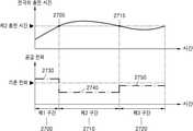
- FIG. 27shows a graph for controlling the power supplied to the heater according to the change in the charging time of the electrode in the aerosol generating device according to an embodiment.
- the processoreg, the processor 1530 of FIG. 15
- supplies power to the heatereg, the heater 1540 of FIG. 15
- the heatereg, the heater 1540 of FIG. 15
- the processor 1530may detect a charging time of the electrode that is shorter than the second charging time specified in the first period 2700 . For example, the processor 1530 may determine that the amount of aerosol generated from the aerosol-generating article is less than the reference atomization amount based on the detected charging time of the electrode. The processor 1530 may supply first power 2730 higher than the reference power to the heater 1540 so that the aerosol amount in the first section 2700 may reach the reference atomization amount. In an embodiment, as the supply power to the heater 1540 is set to the first power 2730 , the charging time of the electrode may gradually increase to reach the designated second charging time 2705 . However, the charging time of the electrode may exceed the specified second charging time after reaching the specified second charging time ( 2705 ).
- the processor 1530may supply second power 2740 lower than the reference power to the heater 1540 so that the aerosol amount in the second section 2710 may reach the reference atomization amount.
- the charging time of the electrodemay gradually decrease to reach the designated second charging time 2715 .
- the charging time of the electrodemay be less than the designated second charging time after reaching the designated second charging time (2715).
- the processor 1530is higher than the reference power to the heater 1540 and lower than the first power 2730 so that the aerosol amount in the third section 2720 can reach the reference atomization amount. (2750) can be supplied. In an embodiment, as the supply power to the heater 1540 is set to the third power 2750, the charging time of the electrode may gradually increase.
- the difference between the generated aerosol amount and the reference atomization amountmay gradually decrease. That is, as the processor 1530 controls the power supply to the heater 1540 based on the charging time of the electrode, the amount of aerosol generated converges to the reference atomization amount.
- FIG. 28is a block diagram of an aerosol generating device according to another embodiment.
- the aerosol generating device 2800may include an electrode 2810 , a battery 2820 , a processor 2830 , a heater 2840 , and a memory 2850 .
- the electrode 2810, the battery 2820, the processor 2830, and the heater 2840 of FIG. 28correspond to the electrode 1510, the battery 1520, the processor 1530 and the heater 1540 of FIG. 15, A duplicate description may be omitted.
- the processor 2830may store data on the user's smoking pattern in the memory 2850 .
- the data on the user's smoking patternmay include at least one of data on the user's puff period and data on the user's puff time (suction time).
- the processor 2830may obtain data on the user's smoking pattern from the memory 2850 to set a reference atomization amount for the aerosol amount generated from the aerosol-generating article.
- the processor 2830may control the power supplied to the heater 2840 so that the aerosol amount reaches a reference atomization amount set based on data on the user's smoking pattern.
- the processor 2830may obtain data about the user's puff period from the memory 2850 . Based on the acquired user's puff period, after the first puff is started, it is possible to determine when the second puff is to be started. Accordingly, the processor 2830 controls the supply power to the heater 2840 so that a reference atomized amount of aerosol can be generated from the aerosol-generating article after the first puff is started until the second puff is started. can
- the processor 2830may obtain data about the user's puff time (suction time) from the memory 2850 . Based on the acquired user's puff time (inhalation time), it is possible to set the reference atomization amount for the aerosol amount. Accordingly, the processor 2830 may control the power supply to the heater 2840 such that a reference atomizing amount of the aerosol may be generated from the aerosol-generating article.
- the processor 2830may monitor the charging time of the electrode 2810 and acquire puff data related to the user's puff based on the monitoring result.
- the puff data related to the user's puffmay mean puff data updated with respect to the user's existing puff data.
- the data on the smoking patternmay be reflected and stored in the memory 2850 .
- 29is a graph illustrating a charging time of an electrode that changes according to a user's smoking pattern according to an exemplary embodiment.
- the processormonitors the charging time of the electrode (eg, the electrode 2810 of FIG. 28 ) to obtain data about the user's puff period, and thereby a memory 2850 ) can be stored in
- the processor 2830may determine the puff cycle of the first user 2900 .
- a first puff period 2905may be obtained as data.
- the processor 2830may configure the first puff cycle 2905 as data on the puff cycle of the second user 2910 .
- a longer second puff period 2915may be obtained.
- the processor 2830When the same reference atomization amount of aerosol is provided to the first user 2900 and the second user 2910 having different puff cycles, the processor 2830 generates a heater (eg, the heater ( 2840)) to control the supply power.
- a heatereg, the heater ( 2840)
- the processor 2830controls the heater 2840 so that the aerosol of the reference atomization amount can be generated during the first puff period 2905 (eg, 5 seconds) from the time when the puff of the first user 2900 is started.
- the supply power to the first powermay be controlled.
- the processor 2830may generate an aerosol of a reference atomization amount during the second puff period 2915 (eg, 8 seconds) from the point in time when the puff of the second user 2910 is started, the heater 2840 ) may be controlled to a second power lower than the first power.
- FIG. 30is a graph illustrating a charging time of an electrode that changes according to a user's smoking pattern according to another embodiment.
- the processormonitors the charging time of the electrode (eg, the electrode 2810 of FIG. 28 ) to obtain data about the user's puff time (suction time) to be stored in a memory (eg, the memory 2850 of FIG. 28 ).
- a memoryeg, the memory 2850 of FIG. 28 .
- the processor 2830may activate the first user
- a first puff time 3005may be obtained as data about a puff time of (3000).
- the processor 2830may determine the puff time of the second user 3010 .
- the second puff time 3015may be obtained as data.
- the processor 2830sets the reference atomization amount based on the user's puff time. can For example, for a first user 3000 inhaling an aerosol during a first puff time 3005 (eg, 1 second) in a first puff period 3020 , the processor 2830 may cause the first user 3000 to The reference atomization amount for can be set as the first reference atomization amount.
- the processor 2830may
- the reference atomization amount for the user 3010may be set as a second reference atomization amount less than the first reference atomization amount.
- the maximum number of puffs that the aerosol-generating article can provide(eg, 15 times) may be equally provided to users having different puff times.
- FIG. 31depicts a flow diagram in which an aerosol-generating device detects removal of an aerosol-generating article, according to an embodiment.
- the flowchart of FIG. 31may correspond to the operation of the processor in section (iii) of FIG. 19 .
- the processoracquires at least one of a charging time of an electrode (eg, the electrode 1510 of FIG. 15 ) or a discharging time of the electrode 1510 in operation 3101 . can do.
- the processor 1530may acquire the charging time of the electrode 1510 based on an input voltage input from the electrode 1510 (eg, the input voltage in FIGS. 17 and 18 ).
- the charging time of the electrode 1510may mean a time required for the charging voltage of the electrode 1510 to reach a predetermined reference voltage (eg, the reference voltage Vref in FIGS. 17 and 18 ).
- the processor 1530may obtain the discharge time of the electrode 1510 based on an input voltage input from the electrode 1510 .
- the discharge time of the electrodemay mean a time required for the charging voltage of the electrode 1510 to reach 0V.
- the processor 1530may determine whether the charging time of the electrode is shorter than the specified third charging time or whether the discharging time of the electrode is longer than the specified third discharging time.
- the specified third charging time and the specified third discharging timeare the charging time and discharging required for the charging voltage of the electrode 1510 having an increased amount of charge as the aerosol-generating article is removed to reach the predetermined reference voltage Vref. Each can mean time.
- the processor 1530is configured to detect removal of the aerosol-generating article in operation 3105 .
- the processor 1530may return to operation 3101 .
- the processor 1530may supply power to the heater 1540 to remove a material adhering to the heater (eg, the heater 1540 of FIG. 15 ). For example, when removal of the aerosol-generating article is detected, the processor 1530 may perform a cleaning operation to remove substances adhering to the heater 1540 by heating the heater 1540 to a high temperature. In this case, the heating temperature of the heater 1540 for the cleaning operation may be higher than the heating temperature of the heater 1540 heating the aerosol-generating article. For example, in order to perform a cleaning operation, the processor 1530 may control the supply power so that the heater 1540 has a temperature range of about 450°C to 550°C.
- the processor 1530may control the supply power so that the heater 1540 has a temperature range of about 500°C to 550°C.
- the heating temperature range for performing the cleaning operation for the heater 1540is exemplary and may be variously changed according to the design of the manufacturer.
- the processor 1530may automatically perform a cleaning operation on the heater 1540 .
- the processor 1530may perform a cleaning operation on the heater 1540 after a specified time (eg, 10 minutes) has elapsed from the time the aerosol-generating article was removed. can run automatically.
- the processor 1530may automatically stop the cleaning operation of the heater 1540 when the insertion of the aerosol-generating article is detected during the cleaning operation.
- FIG. 32illustrates a graph of charging time of an electrode that changes as an aerosol-generating article is removed from an aerosol-generating device according to an embodiment.
- the time interval for determining whether to insert the aerosol-generating article into the aerosol-generating deviceis a first interval 3200 and a second interval 3210 .
- the first section 3200may correspond to a section in which the aerosol-generating article is inserted.
- the second section 3210may correspond to a section after the aerosol-generating article is removed.
- the charging time of the electrode(eg, the electrode 1510 of FIG. 15 ) is increased in the first section 3200 . can do.
- the temperature of the region in which the electrode is disposedmay also increase. As the temperature increases, the charging time required to charge the electrode may gradually increase.
- the charging time of the electrodemay be reduced as the aerosol-generating article is removed. In this case, the charging time of the electrode may be substantially sharply reduced. In an embodiment, when the charging time 3250 of the electrode is shorter than the specified third charging time 3230 , the processor 1530 may determine that the aerosol-generating article has been removed.
- the charging time of the electrode in the first section 3200may be substantially constant. Since the electrode may be continuously discharged even if it does not include a separate discharge circuit, a charging time may be required to charge the amount of electric charge lost as the electrode is discharged. Accordingly, the processor 1530 may continuously apply a predetermined voltage to the electrode.
- the charging time of the electrodemay be reduced as the aerosol-generating article is removed. In this case, the charging time of the electrode may be substantially sharply reduced. In an embodiment, when the charging time 3250 of the electrode is shorter than the specified third charging time 3230 , the processor 1530 may determine that the aerosol-generating article has been removed.
- the processor 1530may determine whether to perform a cleaning operation on the heater 1540 in the second period 3210 based on a change in the charging time of the electrode in the first period 3200 . have. For example, if a substantial change in the charging time of the electrode occurs in the first section 3200, the processor 1530 determines that smoking has progressed before the time point 3220 at which the aerosol-generating article is removed (3260). In section 2 3210 , a cleaning operation for the heater 1540 may be performed. As another example, if a substantial change in the charging time of the electrode does not occur in the first section 3200, the processor 1530 determines that smoking does not proceed before the time point 3220 at which the aerosol-generating article is removed (3270). It is determined that the cleaning operation may not be performed on the heater 1540 in the second section 3210 .
- 33Aillustrates a state before the aerosol-generating article is removed from the aerosol-generating device according to an embodiment.
- 33Billustrates a state after the aerosol-generating article is removed from the aerosol-generating device according to an embodiment.
- the aerosol generating device 3300may include a housing 3301 , an electrode 3310 , a battery 3320 , a processor 3330 , and a heater 3360 .
- the electrode 3310 of FIG. 33Amay include (+) charge equal to the first charge amount.
- the first amount of chargeincreases the moisture of a component (eg, tobacco material 3307) included in the aerosol-generating article 3305 may mean the amount of charge remaining after some (+) charge is lost by Thereafter, when the aerosol-generating article 3305 is removed from the receiving portion 3303 corresponding to the inner circumferential surface of the housing 3301, the electrode 3310 of FIG. +) may contain an electric charge.
- the charging time of the electrode 3310may decrease.
- the processor 3330may detect a decrease in the charging time of the electrode 3310 of FIG. 33B based on an input voltage input from the electrode 3310 .
- the processor 3330may determine that the aerosol-generating article 3305 has been removed when detecting that the charging time of the electrode 3310 is reduced. In another embodiment, the processor 3330 determines that the charging voltage of the electrode 3310 increases based on the decrease in the charging time of the electrode 3310, and the aerosol-generating article 3305 based on the increased charging voltage. It can be considered that this has been removed.
- the processor 3330may perform a cleaning operation on the heater 3360 .
- the processor 3330determines that the aerosol-generating article 3305 has been removed, the aerosol-generating article 3305 is removed from the heater 3360 after a specified time (eg, 10 minutes) has elapsed. cleaning operation can be performed.
- the processor 3330may perform a cleaning operation on the heater 3360 when a user input for executing a cleaning operation on the heater 3360 is received. .
- FIG. 34shows a block diagram of an aerosol generating device according to another embodiment.
- the aerosol generating device 3400may include an electrode 3410 , a battery 3420 , a processor 3430 , and a heater 3460 .
- the electrode 3410, the battery 3420, the processor 3430, and the heater 3460 of FIG. 34correspond to the electrode 1510, the battery 1520, the processor 1530 and the heater 1540 of FIG. 15, A duplicate description may be omitted.
- the processor 3430may include a sensing processor 3440 and a main processor 3450 .
- the sensing processor 3440may include a power module 3442 , a controller 3444 , and a communication module 3446 .
- the power module 3442may receive power from the battery 3420 , and supply the received power to the electrode 3410 through the controller 3444 .
- the controller 3444may apply an output voltage to the electrode 3410 and sense an input voltage input from the electrode 3410 .
- the controller 3444may apply an output voltage to the electrode 3410 by adjusting the PWM method.
- the controller 3444 and the electrode 3410are connected by one line, and the controller 3444 applies an output voltage to the electrode 3410 through the line, and The input voltage can be sensed.
- the controller 3444 and the electrode 3410are connected by at least two or more lines, and the controller 3444 applies an output voltage to the electrode 3410 through one of the at least two or more lines, and An input voltage input from the electrode 3410 through another line may be sensed.
- the communication module 3446may transmit data on a change in the charging time of the electrode 3410 sensed based on an input voltage input from the electrode 3410 to the main processor 3450 .
- the main processor 3450may determine whether to insert the aerosol-generating article based on data about a change in charging time of the electrode 3410 received from the communication module 3446 .
- the main processor 3450may determine that the aerosol-generating article is inserted into the aerosol-generating device 3400 .
- the main processor 3450may apply power to the heater 3460 to cause the heater 3460 to perform a preheating operation.
- the main processor 3450may correspond to a sleep mode while the sensing processor 3440 periodically monitors the charging time of the electrode 3410 .
- the main processor 3450receives information from the sensing processor 3440 indicating that the charging time of the electrode 3410 has increased, the main processor 3450 changes the power state of the main processor 3450 from the low power mode to the active mode. can be switched
Landscapes
- Physics & Mathematics (AREA)
- Electromagnetism (AREA)
- Electrostatic Spraying Apparatus (AREA)
- Disinfection, Sterilisation Or Deodorisation Of Air (AREA)
- Resistance Heating (AREA)
Abstract
Description
Translated fromKorean본 개시에 따른 다양한 실시 예들은, 전극을 포함하는 에어로졸 생성 장치에 관한 것으로, 보다 상세하게는 에어로졸 생성 물품의 유전율에 따른 전극의 전하량의 변화를 감지하여 다양한 제어를 수행할 수 있는 에어로졸 생성 장치에 관한 것이다.Various embodiments according to the present disclosure relate to an aerosol-generating device including an electrode, and more particularly, to an aerosol-generating device capable of performing various controls by sensing a change in the amount of charge of an electrode according to the dielectric constant of an aerosol-generating article. it's about
근래에 일반적인 궐련의 단점들을 극복하는 대체 방법에 관한 수요가 증가하고 있다. 예를 들어, 궐련을 연소시켜 에어로졸을 생성시키는 방법이 아닌 궐련 내의 에어로졸 생성 물질이 가열됨에 따라 에어로졸이 생성되는 방법에 관한 수요가 증가하고 있다. 이에 따라, 가열식 궐련 또는 가열식 에어로졸 발생 장치에 대한 연구가 활발히 진행되고 있다.In recent years, there has been an increasing demand for alternative methods that overcome the disadvantages of conventional cigarettes. For example, there is a growing need for a method in which an aerosol is generated as the aerosol generating material in the cigarette is heated rather than a method in which the aerosol is generated by burning the cigarette. Accordingly, studies on a heated cigarette or a heated aerosol generating device are being actively conducted.
본 개시에 따른 다양한 실시 예에서는 에어로졸 생성 물품의 유전율에 따른 전극의 전하량의 변화를 감지하여 다양한 제어를 수행할 수 있는 에어로졸 생성 장치를 제공하고자 한다.Various embodiments according to the present disclosure provide an aerosol-generating device capable of performing various controls by sensing a change in the amount of electric charge of an electrode according to the dielectric constant of an aerosol-generating article.
본 개시의 실시 예들을 통해 해결하고자 하는 과제가 상술한 과제로 제한되는 것은 아니며, 언급되지 아니한 과제들은 본 명세서 및 첨부된 도면으로부터 실시 예들이 속하는 기술분야에서 통상의 지식을 가진 자에게 명확하게 이해될 수 있을 것이다.The problems to be solved through the embodiments of the present disclosure are not limited to the above-mentioned problems, and the problems not mentioned are clearly understood by those of ordinary skill in the art to which the embodiments belong from the present specification and the accompanying drawings. it could be
일 실시 예에서의 에어로졸 생성 장치는 히터, 에어로졸 생성 물품이 삽입되는 수용부를 포함하는 하우징, 수용부에 삽입된 에어로졸 생성 물품과 이격되어 배치되고 에어로졸 생성 물품의 적어도 일 영역에 대응하게 위치하는 전극, 및 전극과 전기적으로 연결되는 프로세서를 포함할 수 있다.The aerosol-generating device in one embodiment includes a housing including a heater, a housing into which an aerosol-generating article is inserted, and an electrode disposed spaced apart from the aerosol-generating article inserted in the receiving part and positioned to correspond to at least one region of the aerosol-generating article; and a processor electrically connected to the electrode.
본 개시의 다양한 실시 예에 따르면, 에어로졸 생성 물품의 적어도 일 부분을 둘러싸는 포장재의 종류에 관계없이 에어로졸 생성 물품의 삽입 여부를 감지할 수 있다.According to various embodiments of the present disclosure, whether or not the aerosol-generating article is inserted may be detected regardless of the type of packaging material surrounding at least a portion of the aerosol-generating article.
본 개시의 다양한 실시 예에 따르면, 에어로졸 생성 물품의 삽입에 따른 전하량의 변화를 측정하기 위하여 한 개의 전극을 배치함에 따라 이외의 구성 요소들에 대한 설계 변경이 용이해질 수 있다.According to various embodiments of the present disclosure, by disposing one electrode in order to measure the change in the amount of charge due to the insertion of the aerosol-generating article, it may be easy to change the design of the other components.
본 개시의 다양한 실시 예에 따르면, 에어로졸의 유전율을 통해 에어로졸의 발생량을 직접적으로 검출함에 따라, 에어로졸의 발생량 및 이에 기초한 사용자의 퍼프 여부에 대한 데이터의 정확도가 개선될 수 있다.According to various embodiments of the present disclosure, as the amount of aerosol is directly detected through the dielectric constant of the aerosol, the accuracy of data regarding the amount of aerosol generated and whether the user puffs based thereon may be improved.
도 1 내지 도 3은 에어로졸 생성 장치에 에어로졸 생성 물품이 삽입된 예들을 도시한 도면들이다.1 to 3 are views illustrating examples in which an aerosol-generating article is inserted into an aerosol-generating device.
도 4 및 도 5는 에어로졸 생성 물품의 예들을 도시한 도면들이다.4 and 5 are diagrams illustrating examples of aerosol-generating articles.
도 6a는 일 실시 예에 따른 전극과 에어로졸 생성 물품의 관계를 설명하기 위한 개략도를 도시한다.6A shows a schematic diagram for explaining a relationship between an electrode and an aerosol-generating article according to an embodiment.
도 6b는 일 실시 예에 따른 에어로졸 생성 장치의 전극의 위치에 대한 예시도를 도시한다.Figure 6b shows an exemplary view of the position of the electrode of the aerosol generating device according to an embodiment.
도 7a는 일 실시 예에 따른 에어로졸 생성 장치의 하우징의 사시도를 도시한다.7A shows a perspective view of a housing of an aerosol-generating device according to an embodiment.
도 7b는 일 실시 예에 따른 에어로졸 생성 장치의 하우징을 A-A' 방향으로 절단한 단면도를 도시한다.7B is a cross-sectional view of the housing of the aerosol generating device according to an embodiment cut in the A-A' direction.
도 8a는 다른 실시 예에 따른 에어로졸 생성 장치의 하우징의 사시도를 도시한다.8A shows a perspective view of a housing of an aerosol-generating device according to another embodiment;
도 8b는 다른 실시 예에 따른 에어로졸 생성 장치의 하우징을 A-A' 방향으로 절단한 단면도를 도시한다.8B is a cross-sectional view of the housing of the aerosol generating device according to another embodiment, taken in the A-A' direction.
도 9a는 또 다른 실시 예에 따른 에어로졸 생성 장치의 하우징의 사시도를 도시한다.9A shows a perspective view of a housing of an aerosol-generating device according to another embodiment;
도 9b는 또 다른 실시 예에 따른 에어로졸 생성 장치의 하우징을 A-A' 방향으로 절단한 단면도를 도시한다.FIG. 9B is a cross-sectional view showing a housing of an aerosol generating device according to another embodiment, cut in the A-A' direction.
도 10은 다른 실시 예에 따른 에어로졸 생성 장치의 전극의 위치에 대한 예시도를 도시한다.10 shows an exemplary view of the position of the electrode of the aerosol generating device according to another embodiment.
도 11a는 다른 실시 예에 따른 에어로졸 생성 장치의 전극의 위치에 대한 예시도를 도시한다.11A shows an exemplary view of a position of an electrode of an aerosol generating device according to another embodiment.
도 11b는 다른 실시 예에 따른 히터에 대한 전극의 위치에 대한 예시도를 도시한다.11B shows an exemplary view of a position of an electrode with respect to a heater according to another embodiment.
도 12a는 다른 실시 예에 따른 에어로졸 생성 장치의 전극의 위치에 대한 예시도를 도시한다.12A shows an exemplary view of a position of an electrode of an aerosol generating device according to another embodiment.
도 12b는 다른 실시 예에 따른 에어로졸 생성 장치의 전극의 위치에 대한 예시도를 도시한다.12B shows an exemplary view of a position of an electrode of an aerosol generating device according to another embodiment.
도 13a는 다른 실시 예에 따른 에어로졸 생성 장치의 전극의 위치에 대한 예시도를 도시한다.13A shows an exemplary view of a position of an electrode of an aerosol generating device according to another embodiment.
도 13b는 다른 실시 예에 따른 에어로졸 생성 장치의 전극의 위치에 대한 예시도를 도시한다.13B shows an exemplary view of a position of an electrode of an aerosol generating device according to another embodiment.
도 14는 도 13a 및 도 13b에서의 전극에 대한 회로도를 도시한다.Figure 14 shows a circuit diagram for the electrode in Figures 13a and 13b;
도 15는 일 실시 예에 따른 에어로졸 생성 장치의 블록도를 도시한다.15 shows a block diagram of an aerosol generating device according to an embodiment.
도 16a 및 도 16b는 일 실시 예에 따른 에어로졸 생성 장치의 전극이 에어로졸 생성 물품의 종류를 판단하는 방법에 대한 예시도를 도시한다.16A and 16B are diagrams illustrating an example of a method for an electrode of an aerosol-generating device to determine a type of an aerosol-generating article according to an embodiment.
도 17은 일 실시 예에 따른 프로세서가 전극의 충전 시간의 변화를 감지하는 방법을 설명하기 위한 그래프를 도시한다.17 is a graph for explaining a method in which a processor detects a change in a charging time of an electrode according to an embodiment.
도 18은 다른 실시 예에 따른 프로세서가 전극의 충전 시간의 변화를 감지하는 방법을 설명하기 위한 그래프를 도시한다.18 is a graph illustrating a method in which a processor detects a change in a charging time of an electrode according to another exemplary embodiment.
도 19a는 일 실시 예에 따른 에어로졸 생성 장치의 전극의 충전 시간 그래프를 도시한다.19A is a graph illustrating a charging time of an electrode of an aerosol generating device according to an embodiment.
도 19b는 도 19a에서의 전극의 방전 시간 그래프를 도시한다.Fig. 19b shows a graph of discharge time of the electrode in Fig. 19a.
도 20은 일 실시 예에 따른 에어로졸 생성 장치가 에어로졸 생성 물품의 삽입을 감지하는 흐름도를 도시한다.20 depicts a flow diagram in which an aerosol-generating device detects insertion of an aerosol-generating article according to an embodiment.
도 21은 일 실시 예에 따른 에어로졸 생성 장치에 에어로졸 생성 물품이 삽입됨에 따라 변화하는 전극의 충전 시간 그래프를 도시한다.21 is a graph illustrating a charging time of an electrode that changes as an aerosol-generating article is inserted into an aerosol-generating device according to an embodiment.
도 22a는 일 실시 예에 따른 에어로졸 생성 장치에 대하여 에어로졸 생성 물품이 삽입되기 전 상태를 도시한다.22A illustrates a state before the aerosol-generating article is inserted into the aerosol-generating device according to an embodiment.
도 22b는 일 실시 예에 따른 에어로졸 생성 장치에 대하여 에어로졸 생성 물품이 삽입된 후의 상태를 도시한다.22B illustrates a state after the aerosol-generating article is inserted into the aerosol-generating device according to an embodiment.
도 23은 일 실시 예에 따른 에어로졸 생성 장치가 사용자의 퍼프를 검출하는 흐름도를 도시한다.23 is a flowchart illustrating an aerosol generating device detecting a user's puff according to an embodiment.
도 24는 일 실시 예에 따른 에어로졸 생성 장치에서 사용자의 퍼프가 검출됨에 따라 변화하는 전극의 충전 시간 그래프를 도시한다.24 is a graph illustrating a charging time of an electrode that changes as a user's puff is detected in the aerosol generating device according to an embodiment.
도 25a는 일 실시 예에 따른 에어로졸 생성 장치에서 사용자의 퍼프가 검출되기 전의 상태를 도시한다.25A illustrates a state before the user's puff is detected in the aerosol generating device according to an embodiment.
도 25b는 일 실시 예에 따른 에어로졸 생성 장치에서 사용자의 퍼프가 검출된 후의 상태를 도시한다.25B illustrates a state after the user's puff is detected in the aerosol generating device according to an embodiment.
도 26은 일 실시 예에 따른 에어로졸 생성 장치에서 히터에 공급하는 전력을 제어하는 흐름도를 도시한다.26 is a flowchart for controlling the power supplied to the heater in the aerosol generating device according to an embodiment.
도 27은 일 실시 예에 따른 에어로졸 생성 장치에서 전극의 충전 시간이 변화함에 따라 히터에 공급하는 전력을 제어하는 그래프를 도시한다.27 shows a graph for controlling the power supplied to the heater according to the change in the charging time of the electrode in the aerosol generating device according to an embodiment.
도 28은 다른 실시 예에 따른 에어로졸 생성 장치의 블록도를 도시한다.28 is a block diagram of an aerosol generating device according to another embodiment.
도 29는 일 실시 예에 따른 사용자의 흡연 패턴에 따라 변화하는 전극의 충전 시간 그래프를 도시한다.29 is a graph illustrating a charging time of an electrode that changes according to a user's smoking pattern according to an exemplary embodiment.
도 30은 다른 실시 예에 따른 사용자의 흡연 패턴에 따라 변화하는 전극의 충전 시간 그래프를 도시한다.30 is a graph illustrating a charging time of an electrode that changes according to a user's smoking pattern according to another embodiment.
도 31은 일 실시 예에 따른 에어로졸 생성 장치가 에어로졸 생성 물품의 제거를 감지하는 흐름도를 도시한다.31 depicts a flow diagram in which an aerosol-generating device detects removal of an aerosol-generating article, according to an embodiment.
도 32는 일 실시 예에 따른 에어로졸 생성 장치로부터 에어로졸 생성 물품이 제거됨에 따라 변화하는 전극의 충전 시간 그래프를 도시한다.32 illustrates a graph of charging time of an electrode that changes as an aerosol-generating article is removed from an aerosol-generating device according to an embodiment.
도 33a는 일 실시 예에 따른 에어로졸 생성 장치로부터 에어로졸 생성 물품이 제거되기 전 상태를 도시한다.33A illustrates a state before the aerosol-generating article is removed from the aerosol-generating device according to an embodiment.
도 33b는 일 실시 예에 따른 에어로졸 생성 장치로부터 에어로졸 생성 물품이 제거된 후의 상태를 도시한다.33B illustrates a state after the aerosol-generating article is removed from the aerosol-generating device according to an embodiment.
도 34는 또 다른 실시 예에 따른 에어로졸 생성 장치의 블록도를 도시한다.34 shows a block diagram of an aerosol generating device according to another embodiment.
실시 예들에서 사용되는 용어는 실시 예들의 기능을 고려하면서 가능한 현재 널리 사용되는 일반적인 용어들을 선택하였으나, 이는 발명이 속하는 기술분야의 통상의 지식을 가진 자의 의도 또는 판례, 새로운 기술의 출현 등에 따라 달라질 수 있다. 또한, 특정한 경우는 출원인이 임의로 선정한 용어도 있으며, 이 경우 해당되는 설명 부분에서 그 의미를 상세히 기재할 것이다. 따라서 실시 예들의 설명에서 사용되는 용어는 단순한 용어의 명칭이 아닌, 그 용어가 가지는 의미와 본 개시의 전반에 걸친 내용을 토대로 정의되어야 한다.The terms used in the embodiments are selected as currently widely used general terms as possible while considering the functions of the embodiments, which may vary depending on the intention or precedent of a person of ordinary skill in the art to which the invention pertains, the emergence of new technology, etc. have. In addition, in a specific case, there is a term arbitrarily selected by the applicant, and in this case, the meaning will be described in detail in the corresponding description. Therefore, the terms used in the description of the embodiments should be defined based on the meaning of the terms and the contents of the present disclosure, rather than the simple names of terms.
명세서 전체에서 어떤 부분이 어떤 구성요소를 "포함"한다고 할 때, 이는 특별히 반대되는 기재가 없는 한 다른 구성요소를 제외하는 것이 아니라 다른 구성요소를 더 포함할 수 있음을 의미한다. 또한, 명세서에 기재된 "…부", "…모듈" 등의 용어는 적어도 하나의 기능이나 동작을 처리하는 단위를 의미하며, 이는 하드웨어 또는 소프트웨어로 구현되거나 하드웨어와 소프트웨어의 결합으로 구현될 수 있다.In the entire specification, when a part "includes" a certain element, this means that other elements may be further included, rather than excluding other elements, unless otherwise stated. In addition, terms such as “…unit” and “…module” described in the specification mean a unit that processes at least one function or operation, which may be implemented as hardware or software, or may be implemented as a combination of hardware and software.
명세서 전체에서 에어로졸 생성 장치는, 사용자의 입을 통해 사용자의 폐로 직접적으로 흡입 가능한 에어로졸을 발생시키기 위해 에어로졸 생성 물질을 이용하여 에어로졸을 생성하는 장치일 수 있다. 예를 들면, 에어로졸 생성 장치는 홀더(holder)일 수 있다.Throughout the specification, an aerosol-generating device may be a device that generates an aerosol using an aerosol-generating material to generate an inhalable aerosol directly into the user's lungs through the user's mouth. For example, the aerosol generating device may be a holder.
명세서 전체에서 “퍼프”라 함은 사용자의 흡입을 의미하며, 흡입이란 사용자의 입이나 코를 통해 사용자의 구강 내, 비강 내 또는 폐로 끌어 당기는 상황을 의미할 수 있다.Throughout the specification, the term “puff” refers to a user's inhalation, and inhalation may refer to a situation in which the user's mouth or nose is drawn into the user's mouth, nasal cavity, or lungs.
아래에서는 첨부한 도면을 참고하여 실시 예들에 대하여 발명이 속하는 기술 분야에서 통상의 지식을 가진 자가 용이하게 실시할 수 있도록 상세히 설명한다. 그러나 실시 예들은 여러 가지 상이한 형태로 구현될 수 있으며 여기에서 설명하는 실시 예에 한정되지 않는다.Hereinafter, embodiments will be described in detail with reference to the accompanying drawings so that those of ordinary skill in the art can easily carry out the embodiments. However, the embodiments may be implemented in several different forms and are not limited to the embodiments described herein.
이하에서는 도면을 참조하여 본 개시의 실시 예들을 상세히 설명한다.Hereinafter, embodiments of the present disclosure will be described in detail with reference to the drawings.
도 1 내지 도 3은 에어로졸 생성 장치에 에어로졸 생성 물품이 삽입된 예들을 도시한 도면들이다.1 to 3 are views illustrating examples in which an aerosol-generating article is inserted into an aerosol-generating device.
도 1을 참조하면, 에어로졸 생성 장치(1)는 배터리(11), 제어부(12) 및 히터(13)를 포함한다. 도 2 및 도 3을 참조하면, 에어로졸 생성 장치(1)는 증기화기(14)를 더 포함한다. 또한, 에어로졸 생성 장치(1)의 내부 공간에는 궐련(2)이 삽입될 수 있다.Referring to FIG. 1 , the
도 1 내지 도 3에 도시된 에어로졸 생성 장치(1)에는 본 실시 예와 관련된 구성요소들이 도시되어 있다. 따라서, 도 1 내지 도 3에 도시된 구성요소들 외에 다른 범용적인 구성요소들이 에어로졸 생성 장치(1)에 더 포함될 수 있음을 본 실시 예와 관련된 기술분야에서 통상의 지식을 가진 자라면 이해할 수 있다.The
또한, 도 2 및 도 3에는 에어로졸 생성 장치(1)에 히터(13)가 포함되어 있는 것으로 도시되어 있으나, 필요에 따라, 히터(13)는 생략될 수도 있다.In addition, although it is shown that the
도 1에는 배터리(11), 제어부(12) 및 히터(13)가 일렬로 배치된 것으로 도시되어 있다. 또한, 도 2에는 배터리(11), 제어부(12), 증기화기(14) 및 히터(13)가 일렬로 배치된 것으로 도시되어 있다. 또한, 도 3에는 증기화기(14) 및 히터(13)가 병렬로 배치된 것으로 도시되어 있다. 그러나, 에어로졸 생성 장치(1)의 내부 구조는 도 1 내지 도 3에 도시된 것에 한정되지 않는다. 다시 말해, 에어로졸 생성 장치(1)의 설계에 따라, 배터리(11), 제어부(12), 히터(13) 및 증기화기(14)의 배치는 변경될 수 있다.1 illustrates that the
궐련(2)이 에어로졸 생성 장치(1)에 삽입되면, 에어로졸 생성 장치(1)는 히터(13) 및/또는 증기화기(14)를 작동시켜, 에어로졸을 발생시킬 수 있다. 히터(13) 및/또는 증기화기(14)에 의하여 발생된 에어로졸은 궐련(2)을 통과하여 사용자에게 전달된다.When the
필요에 따라, 에어로졸 생성 물품(2)이 에어로졸 생성 장치(1)에 삽입되지 않은 경우에도 에어로졸 생성 장치(1)는 히터(13)를 가열할 수 있다.If desired, the aerosol-generating
배터리(11)는 에어로졸 생성 장치(1)가 동작하는데 이용되는 전력을 공급한다. 예를 들어, 배터리(11)는 히터(13) 또는 증기화기(14)가 가열될 수 있도록 전력을 공급할 수 있고, 제어부(12)가 동작하는데 필요한 전력을 공급할 수 있다. 또한, 배터리(11)는 에어로졸 생성 장치(1)에 설치된 디스플레이, 센서, 모터 등이 동작하는데 필요한 전력을 공급할 수 있다.The
제어부(12)는 에어로졸 생성 장치(1)의 동작을 전반적으로 제어한다. 구체적으로, 제어부(12)는 배터리(11), 히터(13) 및 증기화기(14)뿐 만 아니라 에어로졸 생성 장치(1)에 포함된 다른 구성들의 동작을 제어한다. 또한, 제어부(12)는 에어로졸 생성 장치(1)의 구성들 각각의 상태를 확인하여, 에어로졸 생성 장치(1)가 동작 가능한 상태인지 여부를 판단할 수도 있다.The
제어부(12)는 적어도 하나의 프로세서를 포함한다. 프로세서는 다수의 논리 게이트들의 어레이로 구현될 수도 있고, 범용적인 마이크로 프로세서와 이 마이크로 프로세서에서 실행될 수 있는 프로그램이 저장된 메모리의 조합으로 구현될 수도 있다. 또한, 다른 형태의 하드웨어로 구현될 수도 있음을 본 실시 예가 속하는 기술분야에서 통상의 지식을 가진 자라면 이해할 수 있다.The
히터(13)는 배터리(11)로부터 공급된 전력에 의하여 가열될 수 있다. 예를 들어, 에어로졸 생성 물품이 에어로졸 생성 장치(1)에 삽입되면, 히터(13)는 에어로졸 생성 물품의 외부에 위치할 수 있다. 따라서, 가열된 히터(13)는 에어로졸 생성 물품 내의 에어로졸 생성 물질의 온도를 상승시킬 수 있다.The
히터(13)는 전기 저항성 히터일 수 있다. 예를 들어, 히터(13)에는 전기 전도성 트랙(track)을 포함하고, 전기 전도성 트랙에 전류가 흐름에 따라 히터(13)가 가열될 수 있다. 그러나, 히터(13)는 상술한 예에 한정되지 않으며, 희망 온도까지 가열될 수 있는 것이라면 제한 없이 해당될 수 있다. 여기에서, 희망 온도는 에어로졸 생성 장치(1)에 기 설정되어 있을 수도 있고, 사용자에 의하여 원하는 온도로 설정될 수도 있다.The
한편, 다른 예로, 히터(13)는 유도 가열식 히터일 수 있다. 구체적으로, 히터(13)에는 에어로졸 생성 물품을 유도 가열 방식으로 가열하기 위한 전기 전도성 코일을 포함할 수 있으며, 에어로졸 생성 물품은 유도 가열식 히터에 의해 가열될 수 있는 서셉터를 포함할 수 있다.Meanwhile, as another example, the
예를 들어, 히터(13)는 관 형 가열 요소, 판 형 가열 요소, 침 형 가열 요소 또는 봉 형의 가열 요소를 포함할 수 있으며, 가열 요소의 모양에 따라 에어로졸 생성 물품(2)의 내부 또는 외부를 가열할 수 있다.For example, the
또한, 에어로졸 생성 장치(1)에는 히터(13)가 복수 개 배치될 수도 있다. 이때, 복수 개의 히터(13)들은 에어로졸 생성 물품(2)의 내부에 삽입되도록 배치될 수도 있고, 에어로졸 생성 물품(2)의 외부에 배치될 수도 있다. 또한, 복수 개의 히터(13)들 중 일부는 에어로졸 생성 물품(2)의 내부에 삽입되도록 배치되고, 나머지는 에어로졸 생성 물품(2)의 외부에 배치될 수 있다. 또한, 히터(13)의 형상은 도 1 내지 도 3에 도시된 형상에 한정되지 않고, 다양한 형상으로 제작될 수 있다.In addition, a plurality of
증기화기(14)는 액상 조성물을 가열하여 에어로졸을 생성할 수 있으며, 생성된 에어로졸은 에어로졸 생성 물품(2)을 통과하여 사용자에게 전달될 수 있다. 다시 말해, 증기화기(14)에 의하여 생성된 에어로졸은 에어로졸 생성 장치(1)의 기류 통로를 따라 이동할 수 있고, 기류 통로는 증기화기(14)에 의하여 생성된 에어로졸이 에어로졸 생성 물품을 통과하여 사용자에게 전달될 수 있도록 구성될 수 있다.
예를 들어, 증기화기(14)는 액체 저장부, 액체 전달 수단 및 가열 요소를 포함할 수 있으나, 이에 한정되지 않는다. 예를 들어, 액체 저장부, 액체 전달 수단 및 가열 요소는 독립적인 모듈로서 에어로졸 생성 장치(1)에 포함될 수도 있다.For example, the
액체 저장부는 액상 조성물을 저장할 수 있다. 예를 들어, 액상 조성물은 휘발성 담배 향 성분을 포함하는 담배 함유 물질을 포함하는 액체일 수 있고, 비 담배 물질을 포함하는 액체일 수도 있다. 액체 저장부는 증기화기(14)로부터 탈/부착될 수 있도록 제작될 수도 있고, 증기화기(14)와 일체로서 제작될 수도 있다.The liquid reservoir may store the liquid composition. For example, the liquid composition may be a liquid comprising a tobacco-containing material comprising a volatile tobacco flavor component, or may be a liquid comprising a non-tobacco material. The liquid storage unit may be manufactured to be detachably/attached from the
예를 들어, 액상 조성물은 물, 솔벤트, 에탄올, 식물 추출물, 향료, 향미제, 또는 비타민 혼합물을 포함할 수 있다. 향료는 멘솔, 페퍼민트, 스피아민트 오일, 각종 과일향 성분 등을 포함할 수 있으나, 이에 제한되지 않는다. 향미제는 사용자에게 다양한 향미 또는 풍미를 제공할 수 있는 성분을 포함할 수 있다. 비타민 혼합물은 비타민 A, 비타민 B, 비타민 C 및 비타민 E 중 적어도 하나가 혼합된 것일 수 있으나, 이에 제한되지 않는다. 또한, 액상 조성물은 글리세린 및 프로필렌 글리콜과 같은 에어로졸 형성제를 포함할 수 있다.For example, the liquid composition may include water, a solvent, ethanol, a plant extract, a flavoring, flavoring agent, or a vitamin mixture. The fragrance may include, but is not limited to, menthol, peppermint, spearmint oil, various fruit flavoring ingredients, and the like. Flavoring agents may include ingredients capable of providing a user with a variety of flavors or flavors. The vitamin mixture may be a mixture of at least one of vitamin A, vitamin B, vitamin C, and vitamin E, but is not limited thereto. Liquid compositions may also include aerosol formers such as glycerin and propylene glycol.
액체 전달 수단은 액체 저장부의 액상 조성물을 가열 요소로 전달할 수 있다. 예를 들어, 액체 전달 수단은 면 섬유, 세라믹 섬유, 유리 섬유, 다공성 세라믹과 같은 심지(wick)가 될 수 있으나, 이에 한정되지 않는다.The liquid delivery means may deliver the liquid composition of the liquid reservoir to the heating element. For example, the liquid delivery means may be, but is not limited to, a wick such as cotton fiber, ceramic fiber, glass fiber, or porous ceramic.
가열 요소는 액체 전달 수단에 의해 전달되는 액상 조성물을 가열하기 위한 요소이다. 예를 들어, 가열 요소는 금속 열선, 금속 열판, 세라믹 히터 등이 될 수 있으나, 이에 한정되지 않는다. 또한, 가열 요소는 니크롬선과 같은 전도성 필라멘트로 구성될 수 있고, 액체 전달 수단에 감기는 구조로 배치될 수 있다. 가열 요소는, 전류 공급에 의해 가열될 수 있으며, 가열 요소와 접촉된 액체 조성물에 열을 전달하여, 액체 조성물을 가열할 수 있다. 그 결과, 에어로졸이 생성될 수 있다.The heating element is an element for heating the liquid composition delivered by the liquid delivery means. For example, the heating element may be, but is not limited to, a metal heating wire, a metal heating plate, a ceramic heater, or the like. In addition, the heating element may be composed of a conductive filament, such as a nichrome wire, and may be arranged to be wound around the liquid delivery means. The heating element may be heated by supplying an electrical current, and may transfer heat to the liquid composition in contact with the heating element, thereby heating the liquid composition. As a result, an aerosol may be generated.
예를 들어, 증기화기(14)는 카토마이저(cartomizer) 또는 무화기(atomizer)로 지칭될 수 있으나, 이에 한정되지 않는다.For example, the
한편, 에어로졸 생성 장치(1)는 배터리(11), 제어부(12), 히터(13) 및 증기화기(14) 외에 범용적인 구성들을 더 포함할 수 있다. 예를 들어, 에어로졸 생성 장치(1)는 시각 정보의 출력이 가능한 디스플레이 및/또는 촉각 정보의 출력을 위한 모터를 포함할 수 있다. 또한, 에어로졸 생성 장치(1)는 적어도 하나의 센서(퍼프 감지 센서, 온도 감지 센서, 에어로졸 생성 물품 삽입 감지 센서 등)를 포함할 수 있다. 또한, 에어로졸 생성 장치(1)는 에어로졸 생성 물품(2)이 삽입된 상태에서도 외부 공기가 유입되거나, 내부 기체가 유출 될 수 있는 구조로 제작될 수 있다.Meanwhile, the
도 1 내지 도 3에는 도시되지 않았으나, 에어로졸 생성 장치(1)는 별도의 크래들과 함께 시스템을 구성할 수도 있다. 예를 들어, 크래들은 에어로졸 생성 장치(1)의 배터리(11)의 충전에 이용될 수 있다. 또는, 크래들과 에어로졸 생성 장치(1)가 결합된 상태에서 히터(13)가 가열될 수도 있다.Although not shown in FIGS. 1 to 3 , the
에어로졸 생성 물품(2)은 일반적인 연소형 궐련과 유사할 수 있다. 예를 들어, 에어로졸 생성 물품(2)은 에어로졸 생성 물질을 포함하는 제 1 부분과 필터 등을 포함하는 제 2 부분으로 구분될 수 있다. 또는, 에어로졸 생성 물품(2)의 제 2 부분에도 에어로졸 생성 물질이 포함될 수도 있다. 예를 들어, 과립 또는 캡슐의 형태로 만들어진 에어로졸 생성 물질이 제 2 부분에 삽입될 수도 있다.The aerosol-generating
에어로졸 생성 장치(1)의 내부에는 제 1 부분의 전체가 삽입되고, 제 2 부분은 외부에 노출될 수 있다. 또는, 에어로졸 생성 장치(1)의 내부에 제 1 부분의 일부만 삽입될 수도 있고, 제 1 부분의 전체 및 제 2 부분의 일부가 삽입될 수도 있다. 사용자는 제 2 부분을 입으로 문 상태에서 에어로졸을 흡입할 수 있다. 이때, 에어로졸은 외부 공기가 제 1 부분을 통과함으로써 생성되고, 생성된 에어로졸은 제 2 부분을 통과하여 사용자의 입으로 전달된다.The entire first part may be inserted into the
일 예로서, 외부 공기는 에어로졸 생성 장치(1)에 형성된 적어도 하나의 공기 통로를 통하여 유입될 수 있다. 예를 들어, 에어로졸 생성 장치(1)에 형성된 공기 통로의 개폐 및/또는 공기 통로의 크기는 사용자에 의하여 조절될 수 있다. 이에 따라, 무화량, 끽연감 등이 사용자에 의하여 조절될 수 있다. 다른 예로서, 외부 공기는 에어로졸 생성 물품(2)의 표면에 형성된 적어도 하나의 구멍(hole)을 통하여 에어로졸 생성 물품(2)의 내부로 유입될 수도 있다.As an example, external air may be introduced through at least one air passage formed in the
이하, 도 4 및 도 5를 참조하여, 에어로졸 생성 물품(2)의 예들을 설명한다.Examples of the aerosol-generating
도 4 및 도 5는 에어로졸 생성 물품의 예들을 도시한 도면들이다.4 and 5 are diagrams illustrating examples of aerosol-generating articles.
도 4를 참조하면, 에어로졸 생성 물품(2)은 담배 로드(21) 및 필터 로드(22)를 포함한다. 도 1 내지 도 3을 참조하여 상술한 제 1 부분(21)은 담배 로드(21)를 포함하고, 제 2 부분(22)은 필터 로드(22)를 포함한다.Referring to FIG. 4 , the aerosol-generating
도 4에는 필터 로드(22)가 단일 세그먼트로 도시되어 있으나, 이에 한정되지 않는다. 다시 말해, 필터 로드(22)는 복수의 세그먼트들로 구성될 수도 있다. 예를 들어, 필터 로드(22)는 에어로졸을 냉각하는 세그먼트 및 에어로졸 내에 포함된 소정의 성분을 필터링하는 세그먼트를 포함할 수 있다. 또한, 필요에 따라, 필터 로드(22)에는 다른 기능을 수행하는 적어도 하나의 세그먼트를 더 포함할 수 있다.4, the
에어로졸 생성 물품(2)은 적어도 하나의 래퍼(24)에 의하여 포장될 수 있다. 래퍼(24)에는 외부 공기가 유입되거나 내부 기체가 유출되는 적어도 하나의 구멍(hole)이 형성될 수 있다. 일 예로서, 에어로졸 생성 물품(2)은 하나의 래퍼(24)에 의하여 포장될 수 있다. 다른 예로서, 에어로졸 생성 물품(2)은 2 이상의 래퍼(24)들에 의하여 중첩적으로 포장될 수도 있다. 예를 들어, 제1 래퍼(241)에 의하여 담배 로드(21)가 포장되고, 래퍼들(242, 243, 244)에 의하여 필터 로드(22)가 포장될 수 있다. 그리고, 단일 래퍼(245)에 의하여 에어로졸 생성 물품(2) 전체가 재포장될 수 있다. 만약, 필터 로드(22)가 복수의 세그먼트들로 구성되어 있다면, 각각의 세그먼트가 래퍼들(242, 243, 244)에 의하여 포장될 수 있다.The
담배 로드(21)는 에어로졸 생성 물질을 포함한다. 예를 들어, 에어로졸 생성 물질은 글리세린, 프로필렌 글리콜, 에틸렌 글리콜, 디프로필렌 글리콜, 디에틸렌 글리콜, 트리에틸렌 글리콜, 테트라에틸렌 글리콜 및 올레일 알코올 중 적어도 하나를 포함할 수 있으나, 이에 한정되지 않는다. 또한, 담배 로드(21)는 풍미제, 습윤제 및/또는 유기산(organic acid)과 같은 다른 첨가 물질을 함유할 수 있다. 또한, 담배 로드(21)에는, 멘솔 또는 보습제 등의 가향액이, 담배 로드(21)에 분사됨으로써 첨가할 수 있다.The
담배 로드(21)는 다양하게 제작될 수 있다. 예를 들어, 담배 로드(21)는 시트(sheet)로 제작될 수도 있고, 가닥(strand)으로 제작될 수도 있다. 또한, 담배 로드(21)는 담배 시트가 잘게 잘린 각초로 제작될 수도 있다. 또한, 담배 로드(21)는 열 전도 물질에 의하여 둘러싸일 수 있다. 예를 들어, 열 전도 물질은 알루미늄 호일과 같은 금속 호일일 수 있으나, 이에 한정되지 않는다. 일 예로, 담배 로드(21)를 둘러싸는 열 전도 물질은 담배 로드(21)에 전달되는 열을 고르게 분산시켜 담배 로드에 가해지는 열 전도율을 향상시킬 수 있으며, 이로 인해 담배 맛을 향상시킬 수 있다. 또한, 담배 로드(21)를 둘러싸는 열 전도 물질은 유도 가열식 히터에 의해 가열되는 서셉터로서의 기능을 할 수 있다. 이때, 도면에 도시되지는 않았으나, 담배 로드(21)는 외부를 둘러싸는 열 전도 물질 이외에도 추가의 서셉터를 더 포함할 수 있다.
필터 로드(22)는 셀룰로오스 아세테이트 필터일 수 있다. 한편, 필터 로드(22)의 형상에는 제한이 없다. 예를 들어, 필터 로드(22)는 원기둥 형(type) 로드일 수도 있고, 내부에 중공을 포함하는 튜브 형(type) 로드일 수도 있다. 또한, 필터 로드(22)는 리세스 형(type) 로드일 수도 있다. 만약, 필터 로드(22)가 복수의 세그먼트들로 구성된 경우, 복수의 세그먼트들 중 적어도 하나가 다른 형상으로 제작될 수도 있다.The
또한, 필터 로드(22)에는 적어도 하나의 캡슐(23)이 포함될 수 있다. 여기에서, 캡슐(23)은 향미를 발생시키는 기능을 수행할 수도 있고, 에어로졸을 발생시키는 기능을 수행할 수도 있다. 예를 들어, 캡슐(23)은 향료를 포함하는 액체를 피막으로 감싼 구조일 수 있다. 캡슐(23)은 구형 또는 원통형의 형상을 가질 수 있으나, 이에 제한되지 않는다.In addition, the
도 5를 참조하면, 에어로졸 생성 물품(3)은 전단 플러그(33)를 더 포함할 수 있다. 전단 플러그(33)는 담배 로드(31)에 있어서, 필터 로드(32)에 반대되는 일 측에 위치할 수 있다. 전단 플러그(33)는 담배 로드(31)가 외부로 이탈하는 것을 방지할 수 있으며, 흡연 중에 담배 로드(31)로부터 액상화된 에어로졸이 에어로졸 발생 장치(도 1 내지 도 3의 1)로 흘러 들어가는 것을 방지할 수 있다.Referring to FIG. 5 , the aerosol-generating
필터 로드(32)는 제1 세그먼트(321) 및 제2 세그먼트(322)를 포함할 수 있다. 여기에서, 제1 세그먼트(321)는 도 4의 필터 로드(22)의 제1 세그먼트에 대응될 수 있고, 제2 세그먼트(322)는 도 4의 필터 로드(22)의 제3 세그먼트에 대응될 수 있다.The
에어로졸 생성 물품(3)의 직경 및 전체 길이는 도 4의 에어로졸 생성 물품(2)의 직경 및 전체 길이에 대응될 수 있다. 예를 들어, 전단 플러그(33)의 길이는 약 7mm, 담배 로드(31)의 길이는 약 15mm, 제1 세그먼트(321)의 길이는 약 12mm, 제2 세그먼트(322)의 길이는 약 14mm일 수 있으나, 이에 한정되지 않는다.The diameter and overall length of the aerosol-generating
에어로졸 생성 물품(3)은 적어도 하나의 래퍼(35)에 의하여 포장될 수 있다. 래퍼(35)에는 외부 공기가 유입되거나 내부 기체가 유출되는 적어도 하나의 구멍(hole)이 형성될 수 있다. 예를 들어, 제1 래퍼(351)에 의하여 전단 플러그(33)가 포장되고, 제2 래퍼(352)에 의하여 담배 로드(31)가 포장되고, 제3 래퍼(353)에 의하여 제1 세그먼트(321)가 포장되고, 제4 래퍼(354)에 의하여 제2 세그먼트(322)가 포장될 수 있다. 그리고, 제5 래퍼(355)에 의하여 에어로졸 생성 물품(3) 전체가 재포장될 수 있다.The aerosol-generating
또한, 제5 래퍼(355)에는 적어도 하나의 천공(36)이 형성될 수 있다. 예를 들어, 천공(36)은 담배 로드(31)를 둘러싸는 영역에 형성될 수 있으나, 이에 제한되지 않는다. 천공(36)은 도 2 및 도 3에 도시된 히터(13)에 의하여 형성된 열을 담배 로드(31)의 내부로 전달하는 역할을 수행할 수 있다.In addition, at least one
또한, 제2 세그먼트(322)에는 적어도 하나의 캡슐(34)이 포함될 수 있다. 여기에서, 캡슐(34)은 향미를 발생시키는 기능을 수행할 수도 있고, 에어로졸을 발생시키는 기능을 수행할 수도 있다. 예를 들어, 캡슐(34)은 향료를 포함하는 액체를 피막으로 감싼 구조일 수 있다. 캡슐(34)은 구형 또는 원통형의 형상을 가질 수 있으나, 이에 제한되지 않는다.Also, the
도 6a는 일 실시 예에 따른 전극과 에어로졸 생성 물품의 관계를 설명하기 위한 개략도를 도시한다.6A shows a schematic diagram for explaining a relationship between an electrode and an aerosol-generating article according to an embodiment.
도 6a를 참조하면, 에어로졸 생성 장치(600)는 전극(620) 및 프로세서(640)를 포함할 수 있다. 일 실시 예에서, 프로세서(640)는 전극(620)의 충전 시간 또는 방전 시간에 기초하여 에어로졸 생성 물품(605)의 삽입/제거 여부를 검출하는 기능, 사용자의 퍼프를 검출하는 기능 및 에어로졸 발생량에 따라 히터로 공급하는 전력을 제어하는 기능을 수행할 수 있다. 예를 들어, 프로세서(640)는 전극(620)에 특정 전압을 인가하며 전극(620)의 충전 시간을 측정할 수 있다. 프로세서(640)는 측정된 전극(620)의 충전 시간 또는 충전 시간의 변화에 기초하여 다양한 기능을 수행할 수 있다. 다른 예를 들어, 프로세서(640)는 전극(620)이 자연 방전됨에 따른 전극(620)의 방전 시간을 측정할 수도 있다. 즉, 전극(620)의 충전 전압이 인가되는 전압과 동일한 경우에, 프로세서(640)는 전극(620)의 방전 시간을 측정할 수 있고, 측정된 전극(620)의 방전 시간 또는 방전 시간의 변화에 기초하여 상기 다양한 기능을 수행할 수도 있다.Referring to FIG. 6A , the
일 실시 예에서, 에어로졸 생성 물품(605)이 에어로졸 생성 장치(600)의 일부(예: 수용부)에 삽입되는 경우에, 전극(620)은 삽입된 에어로졸 생성 물품(605)으로부터 소정 거리 이격되어 배치될 수 있다. 예를 들어, 상기 소정 거리는 에어로졸 생성 물품(605)에 의해 발생하는 전극(620)의 충전 시간 또는 방전 시간의 변화가 감지될 수 있는 거리를 의미할 수 있다. 일 실시 예에서, 전극(620)은 삽입된 에어로졸 생성 물품(605)의 적어도 일 영역에 대응하게 위치할 수 있다. 예를 들어, 전극(620)은 에어로졸 생성 물품(605)의 에어로졸 생성 물질이 배치되는 적어도 일 영역에 대응하게 위치할 수 있다.In one embodiment, when the aerosol-generating
도 6b는 일 실시 예에 따른 에어로졸 생성 장치의 전극의 위치에 대한 예시도를 도시한다.Figure 6b shows an exemplary view of the position of the electrode of the aerosol generating device according to an embodiment.
도 6b를 참조하면, 에어로졸 생성 장치(600)는 하우징(610), 전극(620) 및 히터(650)를 포함할 수 있다. 일 실시 예에서, 에어로졸 생성 장치(600)는 에어로졸 생성 물품(605)이 삽입될 수 있는 수용부를 포함할 수 있다. 예를 들어, 하우징(610)은 외주면 및 내주면을 포함하는 실린더(cylinder) 형태에 해당할 수 있다. 이 때, 수용부는 하우징(610)의 내주면에 의해 둘러싸이는 공간을 의미하거나, 하우징(610)의 내주면에 대응되는 영역을 의미할 수 있다. 다만, 하우징(610)의 형태는 이에 한정되지 아니하고, 제조사의 설계에 따라 다양하게 변경될 수 있다.Referring to FIG. 6B , the
일 실시 예에서, 전극(620)은 하우징(610)의 내주면으로부터 하우징(610)의 외주면 방향으로 이격되어 배치될 수 있다. 예를 들어, 하우징(610)은 제1 방향(예: +y 방향)을 따라 연장되고, 전극(620)은 제1 방향과 수직한 방향(예: +x 방향)으로 이격되어 배치될 수 있다. 또한, 전극(620)은 하우징(610)의 내주면으로부터 일정 거리(x)만큼 이격됨에 따라, 하우징(610)의 내주면 및 외주면 사이에 매립되어 배치될 수 있다.In an embodiment, the
전극(620)이 하우징(610)의 내부에 배치됨에 따라, 프로세서가 전극(620)을 통해 측정하는 데이터 측정 결과의 노이즈가 감소될 수 있다. 예를 들어, 전극(620)이 외부로 노출되도록 배치되어 에어로졸 생성 물품(605)과 접촉하면, 전극(620)은 외부의 물질(예: 담뱃잎, 먼지 등)로 인해 데이터 측정에 영향을 받을 수 있다. 이와 달리, 본 개시에 따른 전극(620)은 하우징(610)의 내부에 매립되어 배치되거나 별도의 보호층에 의해 외부로 노출되지 않음으로써, 외부 물질로 인한 오염이 발생하지 않으므로 데이터 측정에 대한 노이즈가 감소되는 효과가 있다.As the
일 실시 예에서, 전극(620)은 에어로졸 생성 물질(630)이 배치되는 적어도 일 영역에 대응하게 배치될 수 있다. 예를 들어, 전극(620)의 위치는 에어로졸 생성 장치(600)의 수용부에 에어로졸 생성 물품(605)이 완전히 삽입됨에 따라 에어로졸 생성 물질(630)이 배치되는 영역에 대응될 수 있다.In an embodiment, the
일 실시 예에서, 히터(650)는 내부 가열형 히터에 해당할 수 있다. 다만, 히터(650)의 종류는 이에 한정되지 아니하고, 본 개시에 따른 다양한 실시 예에서의 히터의 형상은 도 11a 내지 도 13b에서 후술하고자 한다.In an embodiment, the
도 7a는 일 실시 예에 따른 에어로졸 생성 장치의 하우징의 사시도를 도시한다. 도 7b는 일 실시 예에 따른 에어로졸 생성 장치의 하우징을 A-A' 방향으로 절단한 단면도를 도시한다. 도 7a 및 도 7b는 도 6의 에어로졸 생성 장치(600)에 포함되는 전극(620)의 구체적인 일 예시에 해당할 수 있다.7A shows a perspective view of a housing of an aerosol-generating device according to an embodiment. 7B is a cross-sectional view of the housing of the aerosol generating device according to an embodiment cut in the A-A' direction. 7A and 7B may correspond to a specific example of the
일 실시 예에서, 전극(720)은 곡률을 갖지 않는 판의 형태일 수 있다. 일 실시 예에서, 전극(720)은 수용부(715)로부터 일정 거리만큼 이격되어 배치될 수 있다. 이 때, 전극(720)이 곡률을 갖지 않는 판의 형태이므로, 전극(720)의 중심 부분은 수용부(715)로부터 x만큼 이격되고, 전극(720)의 말단 부분은 수용부(715)로부터 x보다 멀리 이격될 수 있다. 수용부(715)와 전극(720)의 중심 부분 사이의 거리 및 수용부(715)와 전극(720) 말단 부분 사이의 거리 간에 차이를 최소화하기 위하여, 전극(720)의 폭(width)은 실질적으로 좁게 형성될 수 있다.In one embodiment, the
도 8a는 다른 실시 예에 따른 에어로졸 생성 장치의 하우징의 사시도를 도시한다. 도 8b는 다른 실시 예에 따른 에어로졸 생성 장치의 하우징을 A-A' 방향으로 절단한 단면도를 도시한다. 도 9a는 또 다른 실시 예에 따른 에어로졸 생성 장치의 하우징의 사시도를 도시한다. 도 9b는 또 다른 실시 예에 따른 에어로졸 생성 장치의 하우징을 A-A' 방향으로 절단한 단면도를 도시한다. 도 8a, 도 8b, 도 9a 및 도 9b는 도 6의 에어로졸 생성 장치(600)에 포함되는 전극(620)의 구체적인 일 예시에 해당할 수 있다.8A shows a perspective view of a housing of an aerosol-generating device according to another embodiment; 8B is a cross-sectional view of the housing of the aerosol generating device according to another embodiment, taken in the A-A' direction. 9A shows a perspective view of a housing of an aerosol-generating device according to another embodiment; FIG. 9B is a cross-sectional view showing a housing of an aerosol generating device according to another embodiment, cut in the A-A' direction. 8A, 8B, 9A and 9B may correspond to a specific example of the
일 실시 예에서, 전극(820, 920)은 특정 곡률(curvature)을 갖는 판의 형태일 수 있다. 예를 들어, 전극(820, 920)은 하우징(810, 910)의 내주면의 곡률보다 작고, 외주면의 곡률보다 큰 곡률을 가질 수 있다. 전극(820, 920)이 곡률을 갖는 판의 형태인 경우에, 전극(820, 920)의 모든 부분(예: 중앙 부분, 말단 부분 등)이 수용부(815, 915)로부터 일정 거리만큼 이격되어 배치될 수 있다.In an embodiment, the
일 실시 예에서, 전극(820, 920)은 수용부(815, 915)로부터 일정 거리(x)만큼 이격되어 수용부(815, 915)의 적어도 일부를 둘러싸도록 배치될 수 있다. 예를 들어, 전극(820)은 수용부(815)의 둘레의 일부(예: 25%)에 대응하는 영역만을 둘러싸도록 배치될 수 있다. 또 다른 예를 들어, 전극(920)은 수용부(915)의 둘레의 일부(예: 90%)에 대응하는 영역을 둘러싸도록 배치될 수도 있다. 다만 전극(620)이 둘러싸는 영역은 이에 한정되지 아니한다.In an embodiment, the
도 10은 다른 실시 예에 따른 에어로졸 생성 장치의 전극의 위치에 대한 예시도를 도시한다.10 shows an exemplary view of the position of the electrode of the aerosol generating device according to another embodiment.
도 10을 참조하면, 에어로졸 생성 장치(1000)는 하우징(1010) 및 전극(1020)을 포함할 수 있다. 일 실시 예에서, 에어로졸 생성 장치(1000)는 에어로졸 생성 물품(1005)이 삽입될 수 있는 수용부를 포함할 수 있다. 예를 들어, 하우징(1010)은 외주면 및 내주면을 포함하는 실린더(cylinder) 형태에 해당할 수 있다. 다만, 하우징(1010)의 형태는 이에 한정되지 아니하고, 제조사의 설계에 따라 다양하게 변경될 수 있다.Referring to FIG. 10 , the
일 실시 예에서, 전극(1020)은 하우징(1010)의 내주면의 일 영역에 접하도록 배치될 수 있다. 이 때, 하우징(1010)의 내주면 상에 별도의 보호층(1040)이 배치될 수 있다. 보호층(1040)은 일정 두께(x)를 갖도록 형성되고, 전극(1020)은 보호층(1040)의 내주면으로부터 일정 거리(x)만큼 이격되어 배치될 수 있다.In an embodiment, the
보호층(1040)은 하우징(1010)과 상이한 재료, 색깔 또는 패턴으로 형성될 수 있다. 예를 들어, 보호층(1040)은 에어로졸 생성 물품(1005) 또는 에어로졸 생성 물품(1005)에 의해 발생하는 에어로졸과 반응하지 않도록 형성된 도금층, 산화막층 등을 의미할 수 있다.The
일 실시 예에서, 전극(1020)은 에어로졸 생성 물질(1030)이 배치되는 적어도 일 영역에 대응하게 배치될 수 있다. 예를 들어, 전극(1020)의 위치는 에어로졸 생성 장치(1000)의 수용부에 에어로졸 생성 물품(1005)이 완전히 삽입됨에 따라 에어로졸 생성 물질(1030)이 배치되는 영역에 대응될 수 있다.In an embodiment, the
도 11a는 다른 실시 예에 따른 에어로졸 생성 장치의 전극의 위치에 대한 예시도를 도시한다. 도 11b는 다른 실시 예에 따른 히터에 대한 전극의 위치에 대한 예시도를 도시한다. 도 11a 및 도 11b는 도 6의 에어로졸 생성 장치(600)에 포함되는 히터(650)의 구체적인 일 예시에 해당할 수 있다.11A shows an exemplary view of a position of an electrode of an aerosol generating device according to another embodiment. 11B shows an exemplary view of a position of an electrode with respect to a heater according to another embodiment. 11A and 11B may correspond to a specific example of the
도 11a 및 도 11b를 참조하면, 에어로졸 생성 장치(1100)는 하우징(1110), 전극(1120) 및 히터(1150)를 포함할 수 있다. 일 실시 예에서, 히터(1150)는 일정 간격에 따라 배열되는 패턴들을 포함하는 필름 히터에 해당할 수 있다. 예를 들어, 히터(1150)는 발열 패턴(1140) 및 전극(1120)을 포함할 수 있다. 발열 패턴(1140)은 필름(예: Polyimide 필름) 형태의 히터(1150) 상에 프린트 될 수 있다. 전극(1120)은 히터(1150)의 적어도 일 부분에 부착될 수 있다. 11A and 11B , the
일 실시 예에서, 전극(1120)은 히터(1150)의 발열 패턴(1140)과 중첩되지 않는 영역에 배치될 수 있다. 예를 들어, 전극(1120)은 A 영역(예: 발열 패턴의 바깥쪽 부분) 및 B 영역(예: 발열 패턴의 안쪽 부분) 중 적어도 일 영역에 배치될 수 있다.In an embodiment, the
도 12a는 다른 실시 예에 따른 에어로졸 생성 장치의 전극의 위치에 대한 예시도를 도시한다. 도 12b는 다른 실시 예에 따른 에어로졸 생성 장치의 전극의 위치에 대한 예시도를 도시한다. 도 12a 및 도 12b는 도 6의 에어로졸 생성 장치(600)에 포함되는 히터(650)의 구체적인 일 예시에 해당할 수 있다.12A shows an exemplary view of a position of an electrode of an aerosol generating device according to another embodiment. 12B shows an exemplary view of a position of an electrode of an aerosol generating device according to another embodiment. 12A and 12B may correspond to a specific example of the
도 12a 및 도 12b를 참조하면, 에어로졸 생성 장치(1200)는 하우징(1210), 전극(1220) 및 히터를 포함할 수 있다.12A and 12B , the
일 실시 예에서, 히터는 내부 가열형 히터(1230) 및 유도 코일(1240)을 포함할 수 있다. 예를 들어, 유도 코일(1240)은 가변 자기장을 유도하여, 에어로졸 생성 장치(1200)의 내부 가열형 히터(1230)를 가열할 수 있다. 이때, 내부 가열형 히터(1230)는 서셉터의 일 예시에 해당할 수 있다.In an embodiment, the heater may include an internal
다른 실시 예에서, 히터는 유도 코일(1240)만을 포함할 수도 있다. 예를 들어, 유도 코일(1240)은 가변 자기장을 유도하여, 에어로졸 생성 물품(1205)의 매질부 영역에 포함되는 서셉터(1250)를 가열할 수 있다.In another embodiment, the heater may include only the
일 실시 예에서, 전극(1220)은 하우징(1210)의 내주면과 유도 코일(1240) 사이에 배치될 수 있다. 일 실시 예에서, 전극(1220)은 유도 코일(1240)로부터 발생되는 가변 자기장에 영향을 미치지 않도록 형성될 수 있다. 예를 들어, 유도 코일(1240)에 의해 발생되는 가변 자기장의 세기가 감소되는 것을 방지하기 위하여, 전극(1220)의 폭(width)은 실질적으로 좁게 형성될 수 있다.In an embodiment, the
도 13a는 다른 실시 예에 따른 에어로졸 생성 장치의 전극의 위치에 대한 예시도를 도시한다. 도 13b는 다른 실시 예에 따른 에어로졸 생성 장치의 전극의 위치에 대한 예시도를 도시한다. 도 13a 및 도 13b는 도 6의 에어로졸 생성 장치(600)에 포함되는 전극(620) 및 히터(650)의 구체적인 일 예시에 해당할 수 있다.13A shows an exemplary view of a position of an electrode of an aerosol generating device according to another embodiment. 13B shows an exemplary view of a position of an electrode of an aerosol generating device according to another embodiment. 13A and 13B may correspond to a specific example of the
도 13a 및 도 13b를 참조하면, 에어로졸 생성 장치(1300)는 하우징(1310) 및 히터를 포함할 수 있다.13A and 13B , the
일 실시 예에서, 히터는 내부 가열형 히터(1330) 및 유도 코일(1340)을 포함할 수 있다. 예를 들어, 유도 코일(1340)은 가변 자기장을 유도하여, 에어로졸 생성 장치(1300)의 내부 가열형 히터(1330)를 가열할 수 있다.In an embodiment, the heater may include an internal
다른 실시 예에서, 히터는 유도 코일(1340)만을 포함할 수도 있다. 예를 들어, 유도 코일(1340)은 가변 자기장을 유도하여, 에어로졸 생성 물품(1305)의 매질부 영역에 포함되는 서셉터(1350)를 가열할 수 있다.In another embodiment, the heater may include only the
일 실시 예에서, 전극(예: 도 6의 전극(620))은 유도 코일(1340)과 일체로 형성될 수 있다. 즉, 유도 코일(1340)은 가변 자기장을 유도하여 가열 대상(예: 내부 가열형 히터, 서셉터)을 가열하면서, 전극의 센싱 기능을 수행할 수 있다. 전극의 센싱 기능에 대한 구체적인 설명은 도 15에서 후술하고자 한다.In an embodiment, the electrode (eg, the
도 14는 도 13a 및 도 13b에서의 전극에 대한 회로도를 도시한다.Figure 14 shows a circuit diagram for the electrode in Figures 13a and 13b;
도 14를 참조하면, 프로세서(예: 도 13a 및 도 13b의 프로세서)는 유도 가열 컨트롤러(1400) 및 센서 컨트롤러(1410)를 포함할 수 있다. 일 실시 예에서, 유도 가열 컨트롤러(1400)는 유도 코일을 통해 가변 자기장을 유도하여 가열 대상(예: 내부 가열형 히터(1330), 서셉터(1350))을 가열할 수 있다. 일 실시 예에서, 센서 컨트롤러(1410)는 유도 코일에 전원을 인가하고, 유도 코일의 충전 시간의 변화를 감지하여 센싱 동작을 수행할 수 있다.Referring to FIG. 14 , a processor (eg, the processor of FIGS. 13A and 13B ) may include an
일 실시 예에서, 유도 코일은 유도 가열 컨트롤러(1400) 또는 센서 컨트롤러(1410)에 의해 선택적으로 제어될 수 있다.In an embodiment, the induction coil may be selectively controlled by the
일 실시 예에서, 유도 코일은 유도 가열 컨트롤러(1400)를 통해 가열 동작을 수행할 수 있다. 이 때, 센서 컨트롤러(1410)와 유도 코일 간의 연결은 단절될 수 있다. 예를 들어, 유도 가열 컨트롤러(1400)가 유도 코일을 통해 가변 자기장을 유도하여 가열 동작을 수행함에 있어서, 스위치 A 및 스위치 C는 온(on) 상태, 스위치 B 및 스위치 D는 오프(off) 상태로 전환될 수 있다.In an embodiment, the induction coil may perform a heating operation through the
일 실시 예에서, 유도 코일은 센서 컨트롤러(1410)를 통해 전원을 인가받고, 센싱 동작을 수행할 수 있다. 예를 들어, 센싱 동작은 에어로졸 생성 물품(예: 도 6a의 에어로졸 생성 물품(605))의 삽입/제거 여부 센싱, 에어로졸 생성 물품(605)에 의해 발생된 무화량 센싱 및 사용자의 퍼프 센싱 중 적어도 하나를 포함할 수 있다. 이 때, 유도 가열 컨트롤러(1400)와 유도 코일 간의 연결은 단절될 수 있다. 예를 들어, 센서 컨트롤러(1410)가 유도 코일의 충전 시간의 변화에 기반하여 센싱 동작을 수행함에 있어서, 스위치 A 및 스위치 C는 오프 상태, 스위치 B 및 스위치 D는 온 상태로 전환될 수 있다. 이 때, 유도 코일이 센서 컨트롤러(1410)를 통해 센싱 동작을 수행하는 경우에, 회로의 일 단은 오픈되어 그라운드(GND) 단자의 역할을 수행할 수 있다. 스위치 C가 오프 상태로 전환되면, 유도 코일의 일 단은 오픈되어 그라운드 단자의 역할을 수행할 수 있다.In an embodiment, the induction coil may receive power through the
도 14는 센서 컨트롤러(1410)와 유도 코일이 두개의 라인으로 연결되도록 도시되어 있으나, 이에 한정되지 아니한다. 다른 실시 예에서, 센서 컨트롤러(1410)와 유도 코일은 스위치 B를 포함하는 하나의 라인만으로 연결될 수도 있다.14 illustrates that the
도 15는 일 실시 예에 따른 에어로졸 생성 장치의 블록도를 도시한다.15 shows a block diagram of an aerosol generating device according to an embodiment.
도 15을 참조하면, 에어로졸 생성 장치(1500)는 전극(1510), 배터리(1520), 프로세서(1530) 및 히터(1540)를 포함할 수 있다.Referring to FIG. 15 , the
전극(1510)은 에어로졸 생성 물품에 따른 변화가 발생하면, 전하량이 변할 수 있다. 예를 들어, 에어로졸 생성 물품에 따른 변화는 에어로졸 생성 물품의 삽입, 제거, 에어로졸 생성 물품에 따른 에어로졸 발생 및 사용자의 퍼프에 의한 에어로졸 제거 등을 포함할 수 있다.The
일 실시 예에서, 에어로졸 생성 장치(1500)에 에어로졸 생성 물품이 삽입되어 전극(1510)과 근접하게 배치되면, 에어로졸 생성 물품에 포함된 구성 요소의 유전율(permittivity, ε)에 따라 전극(1510)의 전하량은 변할 수 있다. 유전율은 부도체의 전기적인 특성을 나타내는 특성 값으로, 외부 전기장에 대해 만들어내는 편극의 크기를 의미할 수 있다. 이 때, 삽입된 에어로졸 생성 물품이 제거되는 경우에도 전극(1510)의 전하량은 변할 수 있다.In one embodiment, when the aerosol-generating article is inserted into the aerosol-generating
예를 들어, 에어로졸 생성 물품이 궐련인 경우에, 궐련은 일정량의 수분 또는 습분을 갖는 포장재(예: 외부 래퍼, 내부 래퍼 등) 및 매질부에 포함되는 고체 상의 흡연 가능 재료(예: 담뱃잎, 과립 형태의 담배 물질 등)를 포함할 수 있다. 이 때, 수분(H2O)의 유전율은 공기의 유전율에 비해 약 80배 정도 크기 때문에, 포장재 및 흡연 가능 재료가 소량의 수분만을 포함하더라도 궐련이 삽입되면, 전극(1510)은 영향을 받을 수 있다.For example, where the aerosol-generating article is a cigarette, the cigarette contains a packaging material having an amount of moisture or moisture (eg, an outer wrapper, an inner wrapper, etc.) and a solid smokeable material (eg, tobacco leaves, granules) included in the medium. form of tobacco substances, etc.). At this time, since the permittivity of water (H2O) is about 80 times greater than that of air, when the cigarette is inserted, even if the packaging material and the smokingable material contain only a small amount of water, the
다른 예를 들어, 에어로졸 생성 물품이 액상의 흡연 가능 재료를 포함하는 카트리지인 경우에도, 높은 유전율 값을 갖는 액체를 포함하므로 카트리지가 삽입되면, 전극(1510)은 영향을 받을 수 있다.As another example, even if the aerosol-generating article is a cartridge comprising a liquid smokeable material, the
일 실시 예에서, 에어로졸 생성 장치(1500)에 에어로졸 생성 물품이 삽입됨에 따라 전극(1510)에 근접하게 배치되면, 전극(1510)의 전하량은 감소할 수 있다. 일 실시 예에서, 에어로졸 생성 장치(1500)로부터 에어로졸 생성 물품이 제거됨에 따라 전극(1510)으로부터 멀어지면, 전극(1510)의 전하량은 증가할 수 있다.In an embodiment, when the aerosol-generating article is disposed in proximity to the
일 실시 예에서, 프로세서(1530)는 에어로졸 생성 물품에 포함된 구성 요소의 유전율을 이용하여 에어로졸 생성 물품의 삽입 또는 제거 여부를 판단할 수 있다. 이를 통해, 에어로졸 생성 물품의 재료는 다양하게 변경될 수 있다. 종래의 에어로졸 생성 장치는 에어로졸 생성 물품의 포장지 또는 포장지 내부에 포함된 알루미늄 박지를 통해 에어로졸 생성 물품의 삽입 여부를 판단하였다. 그러나, 에어로졸 생성 물품에 알루미늄 박지가 포함되지 않더라도, 본 개시에 따른 에어로졸 생성 장치는 에어로졸 생성 물품의 삽입 또는 제거 여부를 판단할 수 있으므로, 제조사는 포장지의 재료를 다양하게 변경할 수 있다.In an embodiment, the
일 실시 예에서, 에어로졸 생성 물품이 가열되어 에어로졸이 발생하면, 에어로졸의 유전율에 따라 전극(1510)의 전하량은 변할 수 있다.In one embodiment, when the aerosol-generating article is heated to generate an aerosol, the amount of electric charge of the
예를 들어, 에어로졸 생성 물품이 히터(1540)에 의해 가열되는 경우에, 일정한 수분을 갖는 에어로졸이 발생될 수 있다. 이 때, 에어로졸의 유전율은 공기의 유전율에 비해 약 80배 정도 크기 때문에, 에어로졸이 발생되면 전극(1510)은 영향을 받을 수 있다.For example, when an aerosol generating article is heated by the
일 실시 예에서, 에어로졸 생성 물품이 가열됨에 따라 에어로졸이 발생하면, 전극(1510)의 전하량이 감소할 수 있다. 일 실시 예에서, 에어로졸 생성 물품이 가열됨에 따라 생성된 에어로졸이 사용자의 퍼프에 의해 제거되면, 전극(1510)의 전하량이 증가할 수 있다.In one embodiment, when the aerosol is generated as the aerosol-generating article is heated, the amount of charge on the
일 실시 예에서, 프로세서(1530)는 에어로졸 생성 물품이 가열됨에 따라 발생하는 에어로졸의 유전율을 이용하여 에어로졸 발생량 및 사용자의 퍼프 여부를 판단할 수 있다. 이를 통해, 에어로졸 생성 장치(1500)는 균일한 무화량을 제공할 수 있고, 별도의 센서 모듈(예: 퍼프 감지 센서)없이 사용자의 퍼프를 감지할 수 있다.In an embodiment, the
배터리(1520)는, 에어로졸 생성 장치(1500)가 동작하는데 필요한 전력을 공급할 수 있다. 예를 들어, 배터리(1520)는 프로세서(1530)가 전극(1510)에서의 전하량의 변화를 검출할 수 있도록 전력을 공급할 수 있다. 또한, 배터리(1520)는 에어로졸 생성 장치(1500) 내에 구비된 다른 하드웨어 구성들, 예를 들어, 각종 센서들(미도시), 사용자 인터페이스(미도시) 및 메모리(미도시)의 동작에 필요한 전력을 공급할 수 있다. 배터리(1520)는 충전이 가능한 배터리이거나 일회용 배터리일 수 있다. 예를 들어, 배터리(1520)는 리튬폴리머(LiPoly) 배터리일 수 있으나, 이에 한정되지 아니한다.The
프로세서(1530)는 에어로졸 생성 장치(1500)의 전반적인 동작을 제어할 수 있다. 예를 들어, 프로세서(1530)는 배터리(1520)뿐만 아니라 에어로졸 생성 장치(1500)에 포함된 다른 구성들의 동작을 제어할 수 있다. 또한, 프로세서(1530)는 에어로졸 생성 장치(1500)의 구성들 각각의 상태를 확인하여, 에어로졸 생성 장치(1500)가 동작 가능한 상태인지 여부를 판단할 수 있다.The
일 실시 예에서, 프로세서(1530)는 전극(1510)의 전압에 기초하여 에어로졸 생성 물품에 따른 변화를 감지할 수 있다. 예를 들어, 프로세서(1530)는 전극(1510)에 대한 출력 전압(Vout) 및 입력 전압(Vin)을 통해 전극(1510)의 충전 시간의 변화를 판단할 수 있다. 프로세서(1530)는 전극(1510)의 충전 시간의 변화에 기초하여 에어로졸 생성 물품에 따른 변화를 감지할 수 있다. 프로세서(1530)가 전극(1510)의 전압을 확인하는 방법에 대한 구체적인 내용은 도 17 및 도 18에서 후술하고자 한다.In an embodiment, the
도 16a 및 도 16b는 일 실시 예에 따른 에어로졸 생성 장치의 전극이 에어로졸 생성 물품의 종류를 판단하는 방법에 대한 예시도를 도시한다. 도 16a 및 도 16b의 에어로졸 생성 장치(1600)는 도 15의 에어로졸 생성 장치(1500)에 대응될 수 있다.16A and 16B are diagrams illustrating an example of a method for an electrode of an aerosol-generating device to determine a type of an aerosol-generating article according to an embodiment. The
도 16a 및 도 16b를 참조하면, 에어로졸 생성 장치(1600)는 하우징(1610)의 내주면을 통해 서로 다른 종류의 에어로졸 생성 물품이 삽입될 수 있다. 예를 들어, 제1 에어로졸 생성 물품(1650)은 제2 에어로졸 생성 물품(1660)보다 담배 물질을 포함하는 영역이 넓을 수 있다. 이 때, 담배 물질은 과립, 캡슐 등의 형태로 형성되는 고체 상 및 액체 상 중 적어도 하나를 포함할 수 있다.16A and 16B , in the
일 실시 예에서, 프로세서(1630)는 에어로졸 생성 물품이 삽입되면, 전극(1620)을 통해 에어로졸 생성 물품의 종류를 판단할 수 있다.In an embodiment, when the aerosol-generating article is inserted, the
예를 들어, 제1 에어로졸 생성 물품(1650)은 제2 에어로졸 생성 물품(1660)보다 담배 물질에 따른 수분을 더 많이 포함할 수 있다. 프로세서(1630)는 에어로졸 생성 물품이 삽입되었을 때, 전극(1620)의 전하량이 더 많이 감소하면 제1 에어로조 생성 물품(1650)이 삽입된 것으로 판단할 수 있다. 프로세서(1630)는 메모리(미도시)에 에어로졸 생성 물품의 종류 별로 감소되는 전극(1620)의 전하량을 저장할 수 있다.For example, the first aerosol-generating
다만, 이는 일 예시에 해당할 뿐, 제1 에어로졸 생성 물품(1650) 및 제2 에어로졸 생성 물품(1660)에 포함되는 담배 물질의 성분비에 따라 제2 에어로졸 생성 물품(1660)이 제1 에어로졸 생성 물품(1650)보다 담배 물질에 따른 수분을 더 많이 포함할 수도 있다.However, this is only an example, and the second aerosol-generating
도 17은 일 실시 예에 따른 프로세서가 전극의 충전 시간의 변화를 감지하는 방법을 설명하기 위한 그래프를 도시한다.17 is a graph for explaining a method in which a processor detects a change in a charging time of an electrode according to an embodiment.
도 17을 참조하면, 프로세서(예: 도 16a 및 도 16b의 프로세서(1630))는 전극(예: 도 16a 및 도 16b의 전극(1620))과 하나의 라인(line)으로 연결될 수 있다. 일 실시 예에서, 프로세서(1630)는 전극(1620)을 충전하기 위해 전극(1620)에 출력 전압을 일정 주기로 인가할 수 있다. 이 때, 출력 전압은 PWM(pulse width modulation) 방식으로 조절되어 인가될 수 있다. 예를 들어, 프로세서(1630)는 전극(1620)을 충전하기 위해 출력 전압을 50ms마다 전극(1620)에 인가할 수 있다.Referring to FIG. 17 , a processor (eg, the
일 실시 예에서, 프로세서(1630)는 기 설정된 횟수(예: 2)만큼 전극(1620)에 출력 전압을 인가한 후에, 전극(1620)으로부터 입력되는 입력 전압을 감지할 수 있다. 예를 들어, 출력 전압의 전압 값은 약 2.8V 내지 3.3V 범위에 해당할 수 있다. 다른 예를 들어, 출력 전압의 전압 값은 약 5V에 해당할 수도 있다. 이 때, 그래프 (a)와 같이 전극(1620)으로부터 입력되는 입력 전압이 기준 전압(Vref)으로 유지되면, 이벤트(예: 에어로졸 생성 물품의 삽입, 사용자의 퍼프 등)가 발생되지 않은 것으로 판단할 수 있다. 프로세서(1630)가 출력 전압을 인가함에 있어서 기 설정된 횟수는 제조사의 설계에 따라 다양하게 변경될 수 있다.In an embodiment, the
일 실시 예에서, 프로세서(1630)는 전극(1620)으로부터 입력되는 입력 전압의 변화를 감지함에 따라 이벤트의 발생 여부를 판단할 수 있다. 예를 들어, 그래프 (b)와 같이 전극(1620)으로부터 입력되는 입력 전압이 기준 전압(Vref)보다 낮게 감지되면, 프로세서(1630)는 이벤트 발생을 감지(1700)할 수 있다. 예를 들어, 전극(1620)으로부터 입력되는 입력 전압이 최초로 기준 전압(Vref)보다 낮게 감지되면, 프로세서(1630)는 에어로졸 생성 물품이 삽입되는 이벤트가 발생한 것으로 판단할 수 있다.In an embodiment, the
일 실시 예에서, 이벤트의 발생에 따라 입력 전압이 기준 전압(Vref)보다 낮아진 후에, 프로세서(1630)는 전극(1620)에 출력 전압을 일정 주기로 인가함에 따라, 입력 전압은 기준 전압(Vref)에 도달될 수 있다.In an embodiment, after the input voltage becomes lower than the reference voltage Vref according to the occurrence of an event, the
도 18은 다른 실시 예에 따른 프로세서가 전극의 충전 시간의 변화를 감지하는 방법을 설명하기 위한 그래프를 도시한다.18 is a graph illustrating a method in which a processor detects a change in a charging time of an electrode according to another exemplary embodiment.
도 18을 참조하면, 프로세서(1630) 및 전극(1620)은 적어도 둘 이상의 라인(line)으로 연결될 수도 있다. 예를 들어, 상기 적어도 둘 이상의 라인은 프로세서(1630)가 전극(1620)을 충전하기 위해 출력 전압을 인가하는 라인 및 전극(1620)의 충전 상태를 전송하기 위해 프로세서(1630)로 입력 전압을 인가하는 라인을 포함할 수 있다.Referring to FIG. 18 , the
일 실시 예에서, 프로세서(1630)는 그래프 (a)와 같이 전극(1620)에 출력 전압을 일정 주기로 인가할 수 있다. 이 때, 출력 전압은 PWM(pulse width modulation) 방식으로 조절되어 인가될 수 있다. 예를 들어, 프로세서(1630)는 전극(1620)을 충전하기 위해 출력 전압을 50ms마다 전극(1620)에 인가할 수 있다. 일 실시 예에서, 프로세서(1630)는 전극(1620)에 출력 전압을 인가함과 동시에 전극(1620)으로부터 입력되는 입력 전압을 감지할 수 있다. 예를 들어, 프로세서(1630)는 전극(1620)의 충전 상태를 확인함에 있어서, 전극(1620)을 충전하기 위한 출력 전압의 출력을 중단하지 않고도 입력 전압을 감지할 수 있다.In an embodiment, the
다만 도 18은 일 예시에 불과할 뿐, 프로세서(1630) 및 전극(1620)이 둘 이상의 라인으로 연결되더라도, 프로세서(1630)는 전극(1620)으로부터 입력되는 입력 전압을 감지함에 있어서, 출력 전압의 출력을 중단할 수도 있다.However, FIG. 18 is only an example, and even if the
도 19a는 일 실시 예에 따른 에어로졸 생성 장치의 전극의 충전 시간 그래프를 도시한다.19A is a graph illustrating a charging time of an electrode of an aerosol generating device according to an embodiment.
도 19a를 참조하면, 에어로졸 생성 장치(예: 도 6의 에어로졸 생성 장치(600))에 에어로졸 생성 물품(예: 도 6의 에어로졸 생성 물품(605))이 삽입되고, 사용자에 의한 퍼프가 수행된 뒤에 에어로졸 생성 물품(605)이 제거되는 동안에, 전극(예: 도 6의 전극(620))의 충전 시간의 변화를 (i)구간, (ii)구간 및 (iii)구간으로 구분할 수 있다.Referring to FIG. 19A , an aerosol-generating article (eg, the aerosol-generating
일 실시 예에서, 프로세서(예: 도 15의 프로세서(1530))는 (i)구간에서 전극(620)의 충전 시간에 기초하여 에어로졸 생성 물품(605)의 삽입을 감지할 수 있다. 일 실시 예에서, 프로세서(1530)는 (ii)구간에서 전극(620)의 충전 시간에 기초하여 사용자의 퍼프를 검출하여 카운팅하고, 히터(예: 도 15의 히터(1540))의 가열 온도를 제어할 수 있다. 일 실시 예에서, 프로세서(1530)는 (iii)구간에서 전극(620)의 충전 시간에 기초하여 에어로졸 생성 물품(605)의 제거를 감지하고, 히터(1540)에 대한 청소 동작을 제어할 수 있다. 각 구간에 대한 프로세서의 구체적인 동작은 도 20 내지 도 33b에서 후술하고자 한다.In an embodiment, the processor (eg, the
도 19b는 도 19a에서의 전극의 방전 시간 그래프를 도시한다.Fig. 19b shows a graph of discharge time of the electrode in Fig. 19a.
도 19b를 참조하면, 에어로졸 생성 장치(예: 도 6의 에어로졸 생성 장치(600))에 에어로졸 생성 물품(예: 도 6의 에어로졸 생성 물품(605))이 삽입되고, 사용자에 의한 퍼프가 수행된 뒤에 에어로졸 생성 물품(605)이 제거되는 동안에, 전극(예: 도 6의 전극(620))의 방전 시간의 변화를 (i)구간, (ii)구간 및 (iii)구간으로 구분할 수 있다.Referring to FIG. 19B , an aerosol-generating article (eg, the aerosol-generating
일 실시 예에서, 프로세서(예: 도 15의 프로세서(1530))는 (i)구간에서 전극(620)의 방전 시간에 기초하여 에어로졸 생성 물품(605)의 삽입을 감지할 수 있다. 일 실시 예에서, 프로세서(1530)는 (ii)구간에서 전극(620)의 방전 시간에 기초하여 사용자의 퍼프를 검출하여 카운팅하고, 히터(예: 도 15의 히터(1540))의 가열 온도를 제어할 수 있다. 일 실시 예에서, 프로세서(1530)는 (iii)구간에서 전극(620)의 방전 시간에 기초하여 에어로졸 생성 물품(605)의 제거를 감지하고, 히터(1540)에 대한 청소 동작을 제어할 수 있다.In an embodiment, the processor (eg, the
다만, 도 19b에서 전극의 방전 시간에 대한 그래프는 도 19a에서의 전극의 충전 시간에 대한 그래프에 대해 상하 반전된 형태로 도시되어 있으나, 이에 제한되지 아니한다.However, the graph of the discharge time of the electrode in FIG. 19B is shown in an inverted form with respect to the graph of the charging time of the electrode in FIG. 19A, but is not limited thereto.
도 20은 일 실시 예에 따른 에어로졸 생성 장치가 에어로졸 생성 물품의 삽입을 감지하는 흐름도를 도시한다. 도 20의 흐름도는 도 19의 (i)구간에서의 프로세서의 동작에 대응될 수 있다.20 depicts a flow diagram in which an aerosol-generating device detects insertion of an aerosol-generating article according to an embodiment. The flowchart of FIG. 20 may correspond to the operation of the processor in section (i) of FIG. 19 .
도 20을 참조하면, 프로세서(예: 도 15의 프로세서(1530))는 동작 2001에서 전극(예: 도 15의 전극(1510))의 충전 시간 또는 방전 시간 중 적어도 하나를 획득할 수 있다. 일 실시 예에서, 프로세서(1530)는 전극(1510)으로부터 입력되는 입력 전압(예: 도 17 및 도 18에서의 입력 전압)에 기초하여 전극(1510)의 충전 시간을 획득할 수 있다. 예를 들어, 전극(1510)의 충전 시간은, 전극(1510)의 충전 전압이 미리 정해진 기준 전압(예: 도 17 및 도 18에서의 기준 전압(Vref))에 도달하는데 필요한 시간을 의미할 수 있다. 다른 실시 예에서, 프로세서(1530)는 전극(1510)으로부터 입력되는 입력 전압에 기초하여 전극(1510)의 방전 시간을 획득할 수 있다. 예를 들어, 전극(1510)의 방전 시간은, 전극(1510)의 충전 전압이 0V에 도달하는데 필요한 시간을 의미할 수 있다.Referring to FIG. 20 , the processor (eg, the
일 실시 예에 따르면, 프로세서(1530)는 동작 2003에서 전극의 충전 시간이 지정된 제1 충전 시간보다 길거나, 전극의 방전 시간이 지정된 제1 방전 시간보다 짧은지 여부를 판단할 수 있다. 예를 들어, 지정된 제1 충전 시간 및 지정된 제1 방전 시간은, 에어로졸 생성 물품이 삽입됨에 따라 전하량이 감소한 전극(1510)의 충전 전압이 미리 정해진 기준 전압(Vref)에 도달하는데 필요한 충전 시간 및 방전 시간을 각각 의미할 수 있다.According to an embodiment, in
일 실시 예에 따르면, 전극의 충전 시간이 지정된 제1 충전 시간보다 길거나 전극의 방전 시간이 지정된 제1 방전 시간보다 짧은 경우에, 프로세서(1530)는 동작 2005에서 에어로졸 생성 물품의 삽입을 검출할 수 있다. 일 실시 예에 따르면, 전극의 충전 시간이 지정된 제1 충전 시간보다 짧거나 전극의 방전 시간이 지정된 제1 방전 시간보다 긴 경우에, 프로세서(1530)는 동작 2001로 되돌아갈 수 있다.According to an embodiment, when the charging time of the electrode is longer than the specified first charging time or the discharging time of the electrode is shorter than the specified first discharging time, the
일 실시 예에 따르면, 프로세서(1530)는 동작 2007에서 히터(예: 도 15의 히터(1540))의 예열을 위해 히터(1540)에 전력을 공급할 수 있다. 예를 들어, 에어로졸 생성 물품의 삽입이 검출되면, 프로세서(1530)는 에어로졸 생성 장치(예: 도 15의 에어로졸 생성 장치(1500))의 자동 시작 기능을 수행하기 위해 히터(1540)에 전력을 공급할 수 있다. 이 때, 히터(1540)는 약 220℃ 내지 230℃, 약 290℃ 내지 300℃ 및 약 330℃ 내지 340℃에 해당하는 예열 온도의 범위 중 어느 하나의 범위를 갖도록 제어될 수 있다. 다만, 예열 온도의 범위는 예시적인 것으로서, 제조사의 설계에 따라 예열 온도의 범위는 다양하게 변경될 수도 있다.According to an embodiment, the
도 21은 일 실시 예에 따른 에어로졸 생성 장치에 에어로졸 생성 물품이 삽입됨에 따라 변화하는 전극의 충전 시간 그래프를 도시한다.21 is a graph illustrating a charging time of an electrode that changes as an aerosol-generating article is inserted into an aerosol-generating device according to an embodiment.
도 21을 참조하면, 에어로졸 생성 장치(예: 도 15의 에어로졸 생성 장치(1500))에 대한 에어로졸 생성 물품의 삽입 여부를 판단하는 시간 구간은 제1 구간(2100), 제2 구간(2110) 및 제3 구간(2120)으로 구분될 수 있다. 제1 구간(2100)은 에어로졸 생성 물품이 삽입되기 이전에 대기하는 구간에 해당할 수 있다. 제2 구간(2110)은 에어로졸 생성 물품이 삽입된 직후에 에어로졸 생성 물품을 예열하기 위하여 준비하는 구간에 해당할 수 있다. 제3 구간(2120)은 에어로졸 생성 물품을 예열하는 구간에 해당할 수 있다.Referring to FIG. 21 , the time interval for determining whether to insert the aerosol-generating article into the aerosol-generating device (eg, the aerosol-generating
일 실시 예에 따르면, 제1 구간(2100)에서 전극(예: 도 15의 전극(1510))을 충전하는데 필요한 충전 시간은 실질적으로 일정할 수 있다. 전극(1510)은 별도의 방전 회로를 포함하지 않더라도 지속적으로 방전될 수 있으므로, 전극(1510)이 방전됨에 따라 손실된 전하량을 충전하기 위한 일정한 충전 시간을 필요로 할 수 있다. 이에 따라, 에어로졸 생성 장치의 프로세서(예: 도 15의 프로세서(1530))는 전극(1510)에 대하여 일정 전압을 지속적으로 인가할 수 있다.According to an embodiment, the charging time required to charge the electrode (eg, the
일 실시 예에서, 에어로졸 생성 물품이 삽입되는 시점(2130)에 전극의 충전 시간은 증가할 수 있다. 이 때, 전극의 충전 시간은 실질적으로 급격하게 증가할 수 있다. 일 실시 예에서, 전극(1610)의 충전 시간(2150)이 지정된 제1 충전 시간(2140)보다 긴 경우에, 프로세서(1530)는 에어로졸 생성 물품이 삽입된 것으로 판단하고, 히터(예: 도 15의 히터(1540))를 예열하도록 제어할 수 있다.In one embodiment, the charging time of the electrode may increase at the
일 실시 예에 따르면, 제2 구간(2110)에서 에어로졸 생성 물품을 예열하기 위하여 준비하는 동안에, 전극(1510)의 충전 시간은 특정 범위 내에서만 변할 수 있다. 일 실시 예에 따르면, 제3 구간(2120)에서 에어로졸 생성 물품을 예열하는 동안에, 전극(1510)의 충전 시간은 점차적으로 증가할 수 있다.According to an embodiment, during preparation for preheating the aerosol-generating article in the
도 22a는 일 실시 예에 따른 에어로졸 생성 장치에 대하여 에어로졸 생성 물품이 삽입되기 전 상태를 도시한다. 도 22b는 일 실시 예에 따른 에어로졸 생성 장치에 대하여 에어로졸 생성 물품이 삽입된 후의 상태를 도시한다.22A illustrates a state before the aerosol-generating article is inserted into the aerosol-generating device according to an embodiment. 22B illustrates a state after the aerosol-generating article is inserted into the aerosol-generating device according to an embodiment.
도 22a 및 도 22b를 참조하면, 에어로졸 생성 장치(2200)는 하우징(2201), 전극(2210), 배터리(2220), 프로세서(2230) 및 히터(2260)를 포함할 수 있다.22A and 22B , the
도 22a의 전극(2210)은 제1 전하량만큼의 (+) 전하를 포함할 수 있다. 이후에, 에어로졸 생성 물품(2205)이 하우징(2201)의 내주면에 해당하는 수용부(2203)에 대해 삽입되는 경우에, 도 22b의 전극(2210)은 에어로졸 생성 물품(2205)에 포함된 구성 요소(예: 담배 물질(2207), 외부 래퍼 등)의 수분에 의해 (+) 전하를 일부 뺏길 수 있다. 이에 따라, 도 22b의 전극(2210)은 상기 제1 전하량보다 적은 제2 전하량만큼의 (+) 전하를 포함할 수 있다.The
도 22b와 같이, 전극(2210)의 (+) 전하가 제1 전하량에서 제2 전하량으로 감소하면, 전극(2210)의 충전 시간은 증가할 수 있다. 프로세서(2230)는 전극(2210)으로부터 입력되는 입력 전압에 기초하여 도 22b의 전극(2210)의 충전 시간이 증가함을 감지할 수 있다.22B , when the (+) charge of the
일 실시 예에서, 프로세서(2230)는 전극(2210)의 충전 시간이 증가함을 감지하는 경우, 에어로졸 생성 물품(2205)이 삽입된 것으로 판단할 수 있다. 다른 실시 예에서, 프로세서(2230)는 전극(2210)의 충전 시간이 증가함에 기반하여 전극(2210)의 충전 전압이 감소함을 판단하고, 상기 감소된 충전 전압에 기초하여 에어로졸 생성 물품(2205)이 삽입된 것으로 판단할 수도 있다.In an embodiment, the
일 실시 예에서, 에어로졸 생성 물품(2205)이 삽입된 것으로 판단되면, 프로세서(2230)는 배터리(2220)로부터 전력을 수신하여 히터(2260)에 전원을 인가할 수 있다. 이 때, 히터(2260)는 내부 가열형 히터일 수 있다. 다만, 히터(2260)는 이에 한정되지 아니하고, 외부 가열형 히터, 유도 코일 및 서셉터 중 적어도 하나를 포함할 수 있다.In an embodiment, if it is determined that the aerosol-generating
도 23은 일 실시 예에 따른 에어로졸 생성 장치가 사용자의 퍼프를 검출하는 흐름도를 도시한다. 도 23의 흐름도는 도 19의 (ii)구간에서의 프로세서의 제1 동작에 대응될 수 있다.23 is a flowchart illustrating an aerosol generating device detecting a user's puff according to an embodiment. The flowchart of FIG. 23 may correspond to the first operation of the processor in section (ii) of FIG. 19 .
도 23을 참조하면, 프로세서(예: 도 15의 프로세서(1530))는 동작 2301에서 전극(예: 도 15의 전극(1510))의 충전 시간의 변화 또는 방전 시간의 변화 중 적어도 하나를 획득할 수 있다. 일 실시 예에서, 프로세서(1530)는 전극의 충전 시간의 변화 또는 방전 시간의 변화에 기초하여 히터(예: 도 15의 히터(1540))에 의해 생성된 에어로졸 양의 변화를 검출할 수 있다. 예를 들어, 프로세서(1530)는 전극(1510)으로부터 입력되는 입력 전압(예: 도 17 및 도 18에서의 입력 전압)에 기초하여 전극(1510)의 충전 시간의 변화를 획득할 수 있다. 일정 시간 동안에 전극(1510)에 대한 충전 시간이 감소하면, 프로세서(1530)는 히터(1540)에 의해 생성된 에어로졸이 제거된 것으로 판단할 수 있다.Referring to FIG. 23 , the processor (eg, the
일 실시 예에 따르면, 프로세서(1530)는 동작 2303에서 전극(1510)의 충전 시간의 변화 기울기가 음의 값이거나 전극(1510)의 방전 시간의 변화 기울기가 양의 값인지 여부를 판단할 수 있다. 예를 들어, 일정 시간 동안에 전극(1510)의 충전 시간의 변화 기울기가 음의 값이거나 전극(1510)의 방전 시간의 변화 기울기가 양의 값인 경우에, 프로세서(1530)는 히터(1540)에 의해 생성된 에어로졸이 사용자의 퍼프(puff)에 의해 감소된 것으로 판단할 수 있다.According to an embodiment, in
일 실시 예에 따르면, 전극(1510)의 충전 시간의 변화 기울기가 음의 값이거나 전극(1510)의 방전 시간의 변화 기울기가 양의 값인 경우에, 프로세서(1530)는 동작 2305에서 사용자의 퍼프를 검출할 수 있다. 일 실시 예에 따르면, 전극(1510)의 충전 시간의 변화 기울기가 0 이상이거나 방전 시간의 변화 기울기가 0 이하인 경우에, 프로세서(1530)는 동작 2301로 되돌아갈 수 있다.According to an embodiment, when the gradient of change in the charging time of the
일 실시 예에 따르면, 사용자의 퍼프가 검출된 경우에, 프로세서(1530)는 동작 2307에서 에어로졸을 생성하기 위해 히터(1540)에 전력을 공급할 수 있다. 예를 들어, 프로세서(1530)는 사용자의 퍼프에 의해 감소된 만큼의 에어로졸을 생성하기 위해 히터(1540)에 소정의 전력을 공급할 수 있다.According to an embodiment, when the user's puff is detected, the
도 24는 일 실시 예에 따른 에어로졸 생성 장치에서 사용자의 퍼프가 검출됨에 따라 변화하는 전극의 충전 시간 그래프를 도시한다.24 is a graph illustrating a charging time of an electrode that changes as a user's puff is detected in the aerosol generating device according to an embodiment.
도 24를 참조하면, 프로세서(예: 도 15의 프로세서(1530))는 전극(예: 도 15의 전극(1510)의 충전 시간을 모니터링하여 사용자의 퍼프 여부에 대한 데이터를 획득할 수 있다.Referring to FIG. 24 , the processor (eg, the
일 실시 예에서, 프로세서(1530)는 전극(1510)의 충전 시간의 변화에 기초하여 사용자의 퍼프를 검출할 수 있다.In an embodiment, the
일 실시 예에서, 전극(1510)의 충전 시간의 변화 기울기가 음의 값인 경우에, 프로세서(1530)는 사용자의 제1 퍼프를 검출할 수 있다. 예를 들어, 프로세서(1530)는 전극(1510)의 충전 시간의 변화 기울기가 0에서 음의 값으로 전환됨을 검출하면, 상기 검출 시점을 사용자의 제1 퍼프가 개시되는 시점(2400)으로 판단할 수 있다. 프로세서(1530)는 전극(1510)의 충전 시간의 변화 기울기가 음의 값에서 0으로 전환됨을 검출하면, 상기 검출 시점을 사용자의 제1 퍼프가 종료되는 시점(2410)으로 판단할 수 있다. 다른 예를 들어, 프로세서(1530)는 전극(1510)의 충전 시간의 변화 기울기가 소정 시간 동안에 음의 값으로 유지되는 경우에, 상기 소정 시간을 사용자의 제1 퍼프 구간으로 검출할 수 있다.In an embodiment, when the gradient of change in the charging time of the
다른 실시 예에서, 전극(1510)의 충전 시간의 변화량(2405)이 지정된 변화량 이상으로 감소하는 경우에, 프로세서(1530)는 사용자의 제1 퍼프를 검출할 수 있다. 예를 들어, 상기 지정된 변화량이 0.5초이고, 전극(1510)의 충전 시간의 변화량(2405)이 0.8초 인 경우에, 프로세서(1530)는 사용자의 퍼프가 발생한 것으로 판단할 수 있다. 다만, 프로세서(1530)는 충전 시간뿐만 아니라 충전 전압의 변화를 통해 검출할 수도 있다. 즉, 전극(1510)의 충전 전압이 지정된 변화량 이상으로 증가하는 경우에, 프로세서(1530)는 사용자의 제1 퍼프를 검출할 수도 있다.In another embodiment, when the
일 실시 예에서, 제1 퍼프가 종료되는 시점(2410)으로부터 제2 퍼프가 개시되는 시점(2420)까지 전극(1510)의 충전 시간은 점차적으로 증가할 수 있다. 예를 들어, 사용자의 제1 퍼프가 종료되면, 다음 퍼프가 개시되기 전까지 에어로졸 생성 물품으로부터 에어로졸이 생성될 수 있고, 상기 생성된 에어로졸로 인해 전극(1510)의 정전용량은 변화할 수 있다. 전극(1510)의 정전용량이 변화함에 따라, 제1 퍼프가 종료되는 시점(2410)으로부터 제2 퍼프가 개시되는 시점(2420)까지 전극(1510)의 충전 시간은 점차적으로 증가하고, 전극(1510)의 충전 시간의 변화 기울기는 양의 값일 수 있다.In an embodiment, the charging time of the
일 실시 예에서, 전극(1510)의 충전 시간의 변화 기울기가 음의 값인 경우에, 프로세서(1530)는 사용자의 제2 퍼프를 검출할 수 있다. 예를 들어, 제1 퍼프가 종료되는 시점(2410) 이후에 전극(1510)의 충전 시간의 변화 기울기가 0에서 음의 값으로 전환됨을 검출하면, 상기 검출 시점을 사용자의 제2 퍼프가 개시되는 시점(2420)으로 판단할 수 있다. 프로세서(1530)는 전극(1510)의 충전 시간의 변화 기울기가 음의 값에서 0으로 전환됨을 검출하면, 상기 검출 시점을 사용자의 제2 퍼프가 종료되는 시점(2430)으로 판단할 수 있다. 다른 예를 들어, 프로세서(1530)는 전극(1510)의 충전 시간의 변화 기울기가 소정 시간 동안에 음의 값으로 유지되는 경우에, 상기 소정 시간을 사용자의 제2 퍼프 구간으로 검출할 수 있다.In an embodiment, when the gradient of change in the charging time of the
도 25a는 일 실시 예에 따른 에어로졸 생성 장치에서 사용자의 퍼프가 검출되기 전의 상태를 도시한다. 도 25b는 일 실시 예에 따른 에어로졸 생성 장치에서 사용자의 퍼프가 검출된 후의 상태를 도시한다.25A illustrates a state before the user's puff is detected in the aerosol generating device according to an embodiment. 25B illustrates a state after the user's puff is detected in the aerosol generating device according to an embodiment.
도 25a 및 도 25b를 참조하면, 에어로졸 생성 장치(2500)는 하우징(2501), 전극(2510), 배터리(2520), 프로세서(2530) 및 히터(2560)를 포함할 수 있다.25A and 25B , the
도 25a의 전극(2510)은 에어로졸 생성 물품(2505)에 포함된 구성 요소(예: 담배 물질(2507))의 수분에 의해 (+) 전하를 일부 뺏길 수 있다. 예를 들어, 에어로졸 생성 물품(2505)이 히터(2560)에 의해 가열됨에 따라 에어로졸이 생성되고, 도 25a의 전극(2510)은 생성된 에어로졸에 의해 (+) 전하를 일부 뺏겨 제1 전하량만큼의 (+) 전하를 포함할 수 있다. 이후에, 생성된 에어로졸이 사용자의 퍼프(2550)에 의해 제거되는 경우에, 도 25b의 전극(2510)은 상기 제1 전하량보다 많은 제2 전하량만큼의 (+) 전하를 포함할 수 있다.The
도 25b와 같이, 전극(2510)의 (+) 전하가 제1 전하량에서 제2 전하량으로 증가하면, 전극(2510)의 충전 시간은 감소할 수 있다. 프로세서(2530)는 전극(2510)으로부터 입력되는 입력 전압에 기초하여 도 25b의 전극(2510)의 충전 시간이 감소함을 감지할 수 있다.25B , when the (+) charge of the
일 실시 예에서, 프로세서(2530)는 전극(2510)의 충전 시간이 감소함을 감지하는 경우, 사용자의 퍼프(2550)가 발생한 것으로 판단할 수 있다. 다른 실시 예에서, 프로세서(2530)는 전극의 충전 시간이 감소함에 기반하여 전극(2510)의 충전 전압이 증가함을 판단하고, 상기 증가된 충전 전압에 기초하여 사용자의 퍼프(2550)가 발생한 것으로 판단할 수도 있다.In an embodiment, when the
일 실시 예에서, 프로세서(2530)는 사용자의 퍼프(2550)를 검출하면, 퍼프 수를 카운팅할 수 있다. 이 때, 카운팅된 퍼프 수가 에어로졸 생성 물품(2505)에 대하여 기 설정된 최대 퍼프 수를 초과하는 경우에, 프로세서(2530)는 히터(2560)로의 전력 공급을 제한할 수 있다. 예를 들어, 에어로졸 생성 물품(2505)에 대하여 기 설정된 최대 퍼프 수가 15회이고 현재 카운팅 된 퍼프 수가 5회이면, 프로세서(2530)는 히터(2560)로 하여금 에어로졸 생성 물품(2505)을 가열할 수 있도록 전력을 공급할 수 있다. 다른 예를 들어, 에어로졸 생성 물품(2505)에 대하여 기 설정된 최대 퍼프 수가 15회이고 현재 카운팅 된 퍼프 수가 16회이면, 프로세서(2530)는 히터(256)를 통한 에어로졸 생성 물품(250)의 가열을 중단하도록 히터(2560)로의 전력 공급을 제한할 수 있다.In an embodiment, the
도 26은 일 실시 예에 따른 에어로졸 생성 장치에서 히터에 공급하는 전력을 제어하는 흐름도를 도시한다. 도 26의 흐름도는 도 19의 (ii)구간에서의 프로세서의 제2 동작에 대응될 수 있다.26 is a flowchart for controlling the power supplied to the heater in the aerosol generating device according to an embodiment. The flowchart of FIG. 26 may correspond to the second operation of the processor in section (ii) of FIG. 19 .
도 26을 참조하면, 프로세서(예: 도 15의 프로세서(1530))는 동작 2601에서 전극(예: 도 15의 전극(1510))의 충전 시간 또는 방전 시간 중 적어도 하나를 획득할 수 있다. 일 실시 예에서, 프로세서(1530)는 전극(1510)으로부터 입력되는 입력 전압(예: 도 17 및 도 18에서의 입력 전압)에 기초하여 전극(1510)의 충전 시간을 획득할 수 있다. 예를 들어, 전극(1510)의 충전 시간은, 전극(1510)의 충전 전압이 미리 정해진 기준 전압(예: 도 17 및 도 18에서의 기준 전압(Vref))에 도달하는데 필요한 충전 시간을 의미할 수 있다. 다른 실시 예에서, 프로세서(1530)는 전극(1510)으로부터 입력되는 입력 전압에 기초하여 전극(1510)의 방전 시간을 획득할 수 있다. 예를 들어, 전극(1510)의 방전 시간은, 전극(1510)의 충전 전압이 0V에 도달하는데 필요한 방전 시간을 의미할 수 있다.Referring to FIG. 26 , the processor (eg, the
일 실시 예에 따르면, 프로세서(1530)는 동작 2603에서 전극(1510)의 충전 시간이 지정된 제2 충전 시간보다 길거나, 전극(1510)의 방전 시간이 지정된 제2 방전 시간보다 짧은지 여부를 판단할 수 있다. 예를 들어, 지정된 제2 충전 시간 및 지정된 제2 방전 시간은, 전극(1510)의 충전 전압이 에어로졸 생성 물품이 가열되어 기준 무화량만큼의 에어로졸이 생성되는 경우의 전압에 도달하는데 필요한 충전 시간 및 방전 시간을 각각 의미할 수 있다. 이때, 기준 무화량은 에어로졸 생성 물품을 통해 사용자에게 균일한 에어로졸 양을 제공하기 위한 기준 발생량을 의미할 수 있다.According to an embodiment, in
일 실시 예에 따르면, 전극의 충전 시간이 지정된 제2 충전 시간보다 길거나 전극의 방전 시간이 지정된 제2 방전 시간보다 짧은 경우에, 프로세서(1530)는 동작 2605에서 히터(1540)에 기준 전력보다 낮은 제1 전력을 공급할 수 있다. 일 실시 예에 따르면, 전극의 충전 시간이 지정된 제2 충전 시간보다 길지 않거나 전극의 방전 시간이 지정된 제2 방전 시간보다 짧지 않은 경우에, 프로세서(1530)는 동작 2607에서 전극의 충전 시간이 지정된 제2 충전 시간보다 짧거나 전극의 방전 시간이 지정된 제2 방전 시간보다 긴지 여부를 판단할 수 있다. 일 실시 예에 따르면, 전극의 충전 시간이 지정된 제2 충전 시간보다 짧거나 전극의 방전 시간이 지정된 제2 방전 시간보다 긴 경우에, 프로세서(1530)는 동작 2609에서 히터(1540)에 기준 전력보다 높은 제2 전력을 공급할 수 있다. 일 실시 예에 따르면, 전극의 충전 시간이 지정된 제2 충전 시간과 동일하거나 전극의 방전 시간이 지정된 제2 방전 시간과 동일한 경우에, 프로세서(1530)는 히터(1540)에 전력을 공급하지 않고 동작을 종료할 수 있다.According to an embodiment, when the charging time of the electrode is longer than the specified second charging time or the discharging time of the electrode is shorter than the specified second discharging time, in
예를 들어, 프로세서(1530)는 에어로졸 생성 물품으로부터 에어로졸이 발생할 수 있도록 히터(1540)에 기준 전력을 공급할 수 있다. 이때, 기준 전력을 공급받는 히터(1540)의 가열 온도는 250℃일 수 있다.For example, the
프로세서(1530)는 전극의 충전 시간 또는 방전 시간을 획득할 수 있고, 획득된 전극의 충전 시간이 지정된 제2 충전 시간보다 길거나 전극의 방전 시간이 지정된 제2 방전 시간보다 짧은지 여부를 판단할 수 있다. 획득된 전극의 충전 시간이 지정된 제2 충전 시간보다 길거나 전극의 방전 시간이 지정된 제2 충전 시간보다 짧은 경우에, 프로세서(1530)는 히터(1540)의 가열 온도를 낮추기 위해 히터(1540)에 대한 공급 전력을 제어할 수 있다. 즉, 프로세서(1530)는 발생된 에어로졸 양이 기준 무화량보다 많은 것으로 판단하고, 히터(1540)의 가열 온도를 250℃에서 230℃로 감소시키기 위하여 히터(1540)에 대한 공급 전력을 기준 전력보다 낮은 제1 전력으로 설정할 수 있다.The
획득된 전극의 충전 시간이 지정된 제2 충전 시간보다 짧거나 전극의 방전 시간이 지정된 제2 방전 시간보다 긴 경우에, 프로세서(1530)는 히터(1540)의 가열 온도를 높이기 위해 히터(1540)에 대한 공급 전력을 제어할 수 있다. 즉, 프로세서(1530)는 발생된 에어로졸 양이 기준 무화량보다 적은 것으로 판단하고, 히터의 가열 온도를 250℃에서 270℃로 증가시키기 위하여 히터(1540)에 대한 공급 전력을 기준 전력보다 높은 제2 전력으로 설정할 수 있다.When the obtained charging time of the electrode is shorter than the specified second charging time or the discharging time of the electrode is longer than the specified second discharging time, the
도 27은 일 실시 예에 따른 에어로졸 생성 장치에서 전극의 충전 시간이 변화함에 따라 히터에 공급하는 전력을 제어하는 그래프를 도시한다.27 shows a graph for controlling the power supplied to the heater according to the change in the charging time of the electrode in the aerosol generating device according to an embodiment.
도 27을 참조하면, 프로세서(예: 도 15의 프로세서(1530))는 에어로졸 생성 물품으로부터 생성되는 에어로졸 양을 일정하게 조절하기 위해서 히터(예: 도 15의 히터(1540))에 대한 공급 전력을 제어할 수 있다.Referring to FIG. 27 , the processor (eg, the
일 실시 예에서, 프로세서(1530)는 제1 구간(2700)에서 지정된 제2 충전 시간보다 짧은 전극의 충전 시간을 검출할 수 있다. 예를 들어, 프로세서(1530)는 상기 검출된 전극의 충전 시간에 기초하여, 에어로졸 생성 물품으로부터 생성된 에어로졸 양이 기준 무화량보다 적은 것으로 판단할 수 있다. 프로세서(1530)는 제1 구간(2700)에서의 에어로졸 양이 기준 무화량에 도달할 수 있도록, 히터(1540)에 기준 전력보다 높은 제1 전력(2730)을 공급할 수 있다. 일 실시 예에서, 히터(1540)에 대한 공급 전력을 제1 전력(2730)으로 설정함에 따라 전극의 충전 시간은 점차적으로 증가하여 지정된 제2 충전 시간에 도달(2705)할 수 있다. 다만, 전극의 충전 시간은 지정된 제2 충전 시간에 도달(2705)한 이후에 상기 지정된 제2 충전 시간을 초과할 수도 있다.In an embodiment, the
일 실시 예에서, 프로세서(1530)는 제2 구간(2710)에서의 에어로졸 양이 기준 무화량에 도달할 수 있도록, 히터(1540)에 기준 전력보다 낮은 제2 전력(2740)을 공급할 수 있다. 일 실시 예에서, 히터(1540)에 대한 공급 전력을 제2 전력(2740)으로 설정함에 따라 전극의 충전 시간은 점차적으로 감소하여 지정된 제2 충전 시간에 도달(2715)할 수 있다. 다만, 전극의 충전 시간은 지정된 제2 충전 시간에 도달(2715)한 이후에 지정된 제2 충전 시간 미만이 될 수 있다.In an embodiment, the
일 실시 예에서, 프로세서(1530)는 제3 구간(2720)에서의 에어로졸 양이 기준 무화량에 도달할 수 있도록, 히터(1540)에 기준 전력보다 높고 제1 전력(2730)보다 낮은 제3 전력(2750)을 공급할 수 있다. 일 실시 예에서, 히터(1540)에 대한 공급 전력을 제3 전력(2750)으로 설정함에 따라 전극의 충전 시간은 점차적으로 증가할 수 있다.In one embodiment, the
일 실시 예에서, 제1 구간(2700)부터 제3 구간(2720)으로 진행됨에 따라, 생성되는 에어로졸 양과 기준 무화량의 차이는 점차적으로 감소할 수 있다. 즉, 프로세서(1530)가 전극의 충전 시간에 기초하여 히터(1540)에 대한 공급 전력을 제어함에 따라, 생성되는 에어로졸 양은 기준 무화량으로 수렴하게 된다.In an embodiment, as the process progresses from the
도 28은 다른 실시 예에 따른 에어로졸 생성 장치의 블록도를 도시한다.28 is a block diagram of an aerosol generating device according to another embodiment.
도 28을 참조하면, 에어로졸 생성 장치(2800)는 전극(2810), 배터리(2820), 프로세서(2830), 히터(2840) 및 메모리(2850)를 포함할 수 있다. 도 28의 전극(2810), 배터리(2820), 프로세서(2830) 및 히터(2840)는 도 15의 전극(1510), 배터리(1520), 프로세서(1530) 및 히터(1540)에 대응되는 바, 중복되는 설명은 생략될 수 있다.Referring to FIG. 28 , the
일 실시 예에서, 프로세서(2830)는 메모리(2850)에 사용자의 흡연 패턴에 대한 데이터를 저장할 수 있다. 예를 들어, 사용자의 흡연 패턴에 대한 데이터는 사용자의 퍼프 주기에 대한 데이터 및 사용자의 퍼프 시간(흡입 시간)에 대한 데이터 중 적어도 하나를 포함할 수 있다.In an embodiment, the
일 실시 예에서, 프로세서(2830)는 메모리(2850)로부터 사용자의 흡연 패턴에 대한 데이터를 획득하여, 에어로졸 생성 물품으로부터 생성되는 에어로졸 양에 대한 기준 무화량을 설정할 수 있다. 프로세서(2830)는 에어로졸 양이 사용자의 흡연 패턴에 대한 데이터에 기반하여 설정된 기준 무화량에 도달할 수 있도록, 히터(2840)에 대한 공급 전력을 제어할 수 있다.In an embodiment, the
일 실시 예에서, 프로세서(2830)는 메모리(2850)로부터 사용자의 퍼프 주기에 대한 데이터를 획득할 수 있다. 획득된 사용자의 퍼프 주기에 기초하여 제1 퍼프가 개시된 후에 제2 퍼프가 개시될 시점을 판단할 수 있다. 이에 따라, 프로세서(2830)는 제1 퍼프가 개시된 이후에, 제2 퍼프가 개시될 시점까지 에어로졸 생성 물품으로부터 기준 무화량의 에어로졸이 생성될 수 있도록, 히터(2840)에 대한 공급 전력을 제어할 수 있다.In an embodiment, the
일 실시 예에서, 프로세서(2830)는 메모리(2850)로부터 사용자의 퍼프 시간(흡입 시간)에 대한 데이터를 획득할 수 있다. 획득한 사용자의 퍼프 시간(흡입 시간)에 기반하여 에어로졸 양에 대한 기준 무화량을 설정할 수 있다. 이에 따라, 프로세서(2830)는 에어로졸 생성 물품으로부터 기준 무화량의 에어로졸이 생성될 수 있도록, 히터(2840)에 대한 공급 전력을 제어할 수 있다.In an embodiment, the
일 실시 예에서, 프로세서(2830)는 전극(2810)의 충전 시간을 모니터링하고, 모니터링 결과에 기반하여 사용자의 퍼프와 관련된 퍼프 데이터를 획득할 수 있다. 예를 들어, 상기 사용자의 퍼프와 관련된 퍼프 데이터는 사용자의 기존 퍼프 데이터에 대하여 업데이트된 퍼프 데이터를 의미할 수 있다. 프로세서(2830)는 메모리(2850)에 사용자의 기존 퍼프 주기에 대하여 “5.5초”로 저장할 수 있다. 이후에, 전극(2810)의 충전 시간의 모니터링 결과, 사용자의 퍼프 주기가 “7초”로 변경된 경우에, 프로세서(2830)는 업데이트된 퍼프 데이터인 “사용자의 퍼프 주기 = 7초”를 사용자의 흡연 패턴에 대한 데이터에 반영하여 메모리(2850)에 저장할 수 있다.In an embodiment, the
도 29는 일 실시 예에 따른 사용자의 흡연 패턴에 따라 변화하는 전극의 충전 시간 그래프를 도시한다.29 is a graph illustrating a charging time of an electrode that changes according to a user's smoking pattern according to an exemplary embodiment.
도 29를 참조하면, 프로세서(예: 도 28의 프로세서(2830))는 전극(예: 도 28의 전극(2810))의 충전 시간을 모니터링하여 사용자의 퍼프 주기에 대한 데이터를 획득하여 메모리(2850)에 저장할 수 있다. 예를 들어, 제1 사용자(2900)가 에어로졸 생성 장치(예: 도 28의 에어로졸 생성 장치(2800))를 통해 흡연을 하는 경우, 프로세서(2830)는 제1 사용자(2900)의 퍼프 주기에 대한 데이터로서 제1 퍼프 주기(2905)를 획득할 수 있다. 다른 예를 들어, 제2 사용자(2910)가 에어로졸 생성 장치(2800)를 통해 흡연을 하는 경우, 프로세서(2830)는 제2 사용자(2910)의 퍼프 주기에 대한 데이터로서 제1 퍼프 주기(2905)보다 긴 제2 퍼프 주기(2915)를 획득할 수 있다.Referring to FIG. 29 , the processor (eg, the
퍼프 주기가 상이한 제1 사용자(2900) 및 제2 사용자(2910)에게 동일한 기준 무화량의 에어로졸을 제공하는 경우, 프로세서(2830)는 사용자의 퍼프 주기에 기반하여 히터(예: 도 28의 히터(2840))에 대한 공급 전력을 제어할 수 있다.When the same reference atomization amount of aerosol is provided to the first user 2900 and the second user 2910 having different puff cycles, the
예를 들어, 프로세서(2830)는 제1 사용자(2900)의 퍼프가 개시된 시점으로부터 제1 퍼프 주기(2905)(예: 5초)동안에 기준 무화량의 에어로졸이 생성될 수 있도록, 히터(2840)에 대한 공급 전력을 제1 전력으로 제어할 수 있다. 다른 예를 들어, 프로세서(2830)는 제2 사용자(2910)의 퍼프가 개시된 시점으로부터 제2 퍼프주기(2915)(예: 8초)동안에 기준 무화량의 에어로졸이 생성될 수 있도록, 히터(2840)에 대한 공급 전력을 제1 전력보다 낮은 제2 전력으로 제어할 수 있다.For example, the
도 30은 다른 실시 예에 따른 사용자의 흡연 패턴에 따라 변화하는 전극의 충전 시간 그래프를 도시한다.30 is a graph illustrating a charging time of an electrode that changes according to a user's smoking pattern according to another embodiment.
도 30을 참조하면, 프로세서(예: 도 28의 프로세서(2830))는 전극(예: 도 28의 전극(2810))의 충전 시간을 모니터링하여 사용자의 퍼프 시간(흡입 시간)에 대한 데이터를 획득하여 메모리(예: 도 28의 메모리(2850))에 저장할 수 있다. 예를 들어, 제1 사용자(3000)가 에어로졸 생성 장치(예: 도 28의 에어로졸 생성 장치(2800))를 통해 제1 퍼프 주기(3020)로 흡연을 하는 경우, 프로세서(2830)는 제1 사용자(3000)의 퍼프 시간에 대한 데이터로서 제1 퍼프 시간(3005)을 획득할 수 있다. 다른 예를 들어, 제2 사용자(3010)가 에어로졸 생성 장치(2800)를 통해 제1 퍼프 주기(3020)로 흡연을 하는 경우에, 프로세서(2830)는 제2 사용자(3010)의 퍼프 시간에 대한 데이터로서 제2 퍼프 시간(3015)을 획득할 수 있다.Referring to FIG. 30 , the processor (eg, the
퍼프 시간(흡입 시간)이 상이한 제1 사용자(3000) 및 제2 사용자(3010)에게 동일한 기준 무화량의 에어로졸을 제공하는 경우, 프로세서(2830)는 사용자의 퍼프 시간에 기반하여 기준 무화량을 설정할 수 있다. 예를 들어, 제1 퍼프 주기(3020)에서 제1 퍼프 시간(3005)(예: 1초)동안에 에어로졸을 흡입하는 제1 사용자(3000)에 대해, 프로세서(2830)는 제1 사용자(3000)에 대한 기준 무화량을 제1 기준 무화량으로 설정할 수 있다. 다른 예를 들어, 제1 퍼프 주기(3020)에서 제1 퍼프 시간(3005)보다 긴 제2 퍼프 시간(3015)동안 에어로졸을 흡입하는 제2 사용자(3010)에 대해, 프로세서(2830)는 제2 사용자(3010)에 대한 기준 무화량을 제1 기준 무화량보다 적은 제2 기준 무화량으로 설정할 수 있다.When the same reference atomization amount of aerosol is provided to the first user 3000 and the second user 3010 having different puff times (inhalation times), the
사용자의 퍼프 시간에 기반하여 기준 무화량을 설정함에 따라, 서로 다른 퍼프 시간을 갖는 사용자에게 에어로졸 생성 물품이 제공할 수 있는 최대 퍼프 수(예: 15회)를 동일하게 제공할 수 있다.As the reference atomization amount is set based on the user's puff time, the maximum number of puffs that the aerosol-generating article can provide (eg, 15 times) may be equally provided to users having different puff times.
도 31은 일 실시 예에 따른 에어로졸 생성 장치가 에어로졸 생성 물품의 제거를 감지하는 흐름도를 도시한다. 도 31의 흐름도는 도 19의 (iii)구간에서의 프로세서의 동작에 대응될 수 있다.31 depicts a flow diagram in which an aerosol-generating device detects removal of an aerosol-generating article, according to an embodiment. The flowchart of FIG. 31 may correspond to the operation of the processor in section (iii) of FIG. 19 .
도 31을 참조하면, 프로세서(예: 도 15의 프로세서(1530))는 동작 3101에서 전극(예: 도 15의 전극(1510))의 충전 시간 또는 전극(1510)의 방전 시간 중 적어도 하나를 획득할 수 있다. 일 실시 예에서, 프로세서(1530)는 전극(1510)으로부터 입력되는 입력 전압(예: 도 17 및 도 18에서의 입력 전압)에 기초하여 전극(1510)의 충전 시간을 획득할 수 있다. 예를 들어, 전극(1510)의 충전 시간은, 전극(1510)의 충전 전압이 미리 정해진 기준 전압(예: 도 17 및 도 18에서의 기준 전압(Vref))에 도달하는데 필요한 시간을 의미할 수 있다. 다른 실시 예에서, 프로세서(1530)는 전극(1510)으로부터 입력되는 입력 전압에 기초하여 전극(1510)의 방전 시간을 획득할 수 있다. 예를 들어, 전극의 방전 시간은, 전극(1510)의 충전 전압이 0V에 도달하는데 필요한 시간을 의미할 수 있다.Referring to FIG. 31 , the processor (eg, the
일 실시 예에 따르면, 프로세서(1530)는 동작 3103에서 전극의 충전 시간이 지정된 제3 충전 시간보다 짧거나, 전극의 방전 시간이 지정된 제3 방전 시간보다 긴지 여부를 판단할 수 있다. 예를 들어, 지정된 제3 충전 시간 및 지정된 제3 방전 시간은, 에어로졸 생성 물품이 제거됨에 따라 전하량이 증가한 전극(1510)의 충전 전압이 미리 정해진 기준 전압(Vref)에 도달하는데 필요한 충전 시간 및 방전 시간을 각각 의미할 수 있다.According to an embodiment, in
일 실시 예에 따르면, 전극의 충전 시간이 지정된 제3 충전 시간보다 짧거나 전극의 방전 시간이 지정된 제3 방전 시간보다 긴 경우에, 프로세서(1530)는 동작 3105에서 에어로졸 생성 물품의 제거를 검출할 수 있다. 일 실시 예에 따르면, 전극의 충전 시간이 지정된 제3 충전 시간보다 길거나 전극의 방전 시간이 지정된 제3 방전 시간보다 짧은 경우에, 프로세서(1530)는 동작 3101로 되돌아갈 수 있다.According to an embodiment, if the charging time of the electrode is shorter than the third specified charging time or the discharging time of the electrode is longer than the third specified discharging time, the
일 실시 예에 따르면, 프로세서(1530)는 동작 3107에서 히터(예: 도 15의 히터(1540)) 상에 부착된 물질을 제거하기 위해 히터(1540)에 전력을 공급할 수 있다. 예를 들어, 에어로졸 생성 물품의 제거가 검출되면, 프로세서(1530)는 히터(1540)를 고온으로 가열함으로써 히터(1540)에 부착된 물질을 제거하는 청소 동작을 수행할 수 있다. 이 때, 청소 동작을 위한 히터(1540)의 가열 온도는 에어로졸 생성 물품을 가열하는 히터(1540)의 가열 온도보다 높을 수 있다. 예를 들어, 청소 동작을 수행하기 위해, 프로세서(1530)는 히터(1540)가 약 450℃ 내지 550℃의 온도 범위를 갖도록 공급 전력을 제어할 수 있다. 더 바람직하게, 청소 동작을 수행하기 위해, 프로세서(1530)는 히터(1540)가 약 500℃ 내지 550℃의 온도 범위를 갖도록 공급 전력을 제어할 수 있다. 다만, 히터(1540)에 대한 청소 동작을 실행하기 위한 상기 가열 온도 범위는 예시적인 것으로서, 제조사의 설계에 따라 다양하게 변경될 수도 있다.According to an embodiment, in
일 실시 예에서, 프로세서(1530)는 에어로졸 생성 물품의 제거가 검출되면, 히터(1540)에 대한 청소 동작을 자동으로 실행할 수 있다. 예를 들어, 에어로졸 생성 장치로부터 에어로졸 생성 물품의 제거가 검출되면, 프로세서(1530)는 에어로졸 생성 물품이 제거된 시점으로부터 지정된 시간(예: 10분)이 지난 후에 히터(1540)에 대한 청소 동작을 자동으로 실행할 수 있다. 일 실시 예에서, 프로세서(1530)는 청소 동작 중에 에어로졸 생성 물품의 삽입이 검출되면, 자동으로 히터(1540)에 대한 청소 동작을 중단할 수 있다.In an embodiment, when the removal of the aerosol-generating article is detected, the
도 32는 일 실시 예에 따른 에어로졸 생성 장치로부터 에어로졸 생성 물품이 제거됨에 따라 변화하는 전극의 충전 시간 그래프를 도시한다.32 illustrates a graph of charging time of an electrode that changes as an aerosol-generating article is removed from an aerosol-generating device according to an embodiment.
도 32를 참조하면, 에어로졸 생성 장치(예: 도 15의 에어로졸 생성 장치(1500))에 대한 에어로졸 생성 물품의 삽입 여부를 판단하는 시간 구간은 제1 구간(3200) 및 제2 구간(3210)으로 구분될 수 있다. 제1 구간(3200)은 에어로졸 생성 물품이 삽입되어 있는 구간에 해당할 수 있다. 제2 구간(3210)은 에어로졸 생성 물품이 제거된 이후의 구간에 해당할 수 있다.Referring to FIG. 32 , the time interval for determining whether to insert the aerosol-generating article into the aerosol-generating device (eg, the aerosol-generating
일 실시 예에서, 에어로졸 생성 물품이 제거되는 시점(3220) 이전에 흡연이 진행된 경우(3260)에는, 제1 구간(3200)에서 전극(예: 도 15의 전극(1510))의 충전 시간이 증가할 수 있다. 예를 들어, 제1 구간(3200)에서 에어로졸 생성 물품이 가열됨에 따라 전극이 배치된 영역의 온도도 함께 상승할 수 있다. 온도가 상승함에 따라 전극을 충전하는데 필요한 충전 시간은 점차적으로 증가할 수 있다.In one embodiment, if smoking proceeds 3260 before the
에어로졸 생성 물품이 제거되는 시점(3220) 이전에 흡연이 진행된 경우(3260)에는, 에어로졸 생성 물품이 제거됨에 따라 전극의 충전 시간은 감소될 수 있다. 이 때, 전극의 충전 시간은 실질적으로 급격하게 감소할 수 있다. 일 실시 예에서, 전극의 충전 시간(3250)이 지정된 제3 충전 시간(3230) 보다 짧은 경우에, 프로세서(1530)는 에어로졸 생성 물품이 제거된 것으로 판단할 수 있다.If smoking has occurred ( 3260 ) prior to the point in
다른 실시 예에서, 에어로졸 생성 물품이 제거되는 시점(3220) 이전에 흡연이 진행되지 않은 경우(3270)에는, 제1 구간(3200)에서 전극의 충전 시간이 실질적으로 일정할 수 있다. 전극은 별도의 방전 회로를 포함하지 않더라도 지속적으로 방전될 수 있으므로, 전극이 방전됨에 따라 손실된 전하량을 충전하기 위한 충전 시간을 필요로 할 수 있다. 이에 따라, 프로세서(1530)는 전극에 대하여 일정 전압을 지속적으로 인가할 수 있다.In another embodiment, when smoking does not proceed ( 3270 ) before the
에어로졸 생성 물품이 제거되는 시점(3220) 이전에 흡연이 진행되지 않은 경우(3270)에는, 에어로졸 생성 물품이 제거됨에 따라 전극의 충전 시간은 감소될 수 있다. 이 때, 전극의 충전 시간은 실질적으로 급격하게 감소할 수 있다. 일 실시 예에서, 전극의 충전 시간(3250)이 지정된 제3 충전 시간(3230) 보다 짧은 경우에, 프로세서(1530)는 에어로졸 생성 물품이 제거된 것으로 판단할 수 있다.If smoking has not progressed ( 3270 ) prior to the point in
일 실시 예에서, 프로세서(1530)는 제1 구간(3200)에서의 전극의 충전 시간의 변화에 기반하여 제2 구간(3210)에서의 히터(1540)에 대한 청소 동작의 실행 여부를 판단할 수 있다. 예를 들어, 프로세서(1530)는 제1 구간(3200)에서 전극의 충전 시간의 실질적인 변화가 발생하면, 에어로졸 생성 물품이 제거되는 시점(3220) 이전에 흡연이 진행된 경우(3260)로 판단하여 제2 구간(3210)에서 히터(1540)에 대한 청소 동작을 실행할 수 있다. 다른 예를 들어, 프로세서(1530)는 제1 구간(3200)에서 전극의 충전 시간의 실질적인 변화가 발생하지 않으면, 에어로졸 생성 물품이 제거되는 시점(3220) 이전에 흡연이 진행되지 않은 경우(3270)로 판단하여 제2 구간(3210)에서 히터(1540)에 대한 청소 동작을 실행하지 않을 수 있다.In an embodiment, the
도 33a는 일 실시 예에 따른 에어로졸 생성 장치로부터 에어로졸 생성 물품이 제거되기 전 상태를 도시한다. 도 33b는 일 실시 예에 따른 에어로졸 생성 장치로부터 에어로졸 생성 물품이 제거된 후의 상태를 도시한다.33A illustrates a state before the aerosol-generating article is removed from the aerosol-generating device according to an embodiment. 33B illustrates a state after the aerosol-generating article is removed from the aerosol-generating device according to an embodiment.
도 33a 및 도 33b를 참조하면, 에어로졸 생성 장치(3300)는 하우징(3301), 전극(3310), 배터리(3320), 프로세서(3330) 및 히터(3360)를 포함할 수 있다.33A and 33B , the
도 33a의 전극(3310)은 제1 전하량만큼의 (+) 전하를 포함할 수 있다. 상기 제1 전하량은, 도 33a와 같이 에어로졸 생성 물품(3305)이 전극(3310)과 근접하게 배치됨에 따라, 에어로졸 생성 물품(3305)에 포함된 구성 요소(예: 담배 물질(3307))의 수분에 의해 (+) 전하를 일부 뺏기고 남은 전하량을 의미할 수 있다. 이후에, 에어로졸 생성 물품(3305)이 하우징(3301)의 내주면에 해당하는 수용부(3303)로부터 제거되는 경우에, 도 33b의 전극(3310)은 상기 제1 전하량보다 많은 제2 전하량만큼의 (+) 전하를 포함할 수 있다.The
도 33b와 같이, 전극(3310)의 (+) 전하가 제1 전하량에서 제2 전하량으로 증가하면, 전극(3310)의 충전 시간은 감소할 수 있다. 프로세서(3330)는 전극(3310)으로부터 입력되는 입력 전압에 기초하여 도 33b의 전극(3310)의 충전 시간이 감소함을 감지할 수 있다.33B , when the (+) charge of the
일 실시 예에서, 프로세서(3330)는 전극(3310)의 충전 시간이 감소함을 감지하는 경우, 에어로졸 생성 물품(3305)이 제거된 것으로 판단할 수 있다. 다른 실시 예에서, 프로세서(3330)는 전극(3310)의 충전 시간이 감소함에 기반하여 전극(3310)의 충전 전압이 증가함을 판단하고, 상기 증가된 충전 전압에 기초하여 에어로졸 생성 물품(3305)이 제거된 것으로 판단할 수 있다.In an embodiment, the
일 실시 예에서, 에어로졸 생성 물품(3305)이 제거된 것으로 판단되면, 프로세서(3330)는 히터(3360)에 대한 청소 동작을 실행할 수 있다. 일 실시 예에서, 프로세서(3330)는 에어로졸 생성 물품(3305)이 제거된 것으로 판단되면, 에어로졸 생성 물품(3305)이 제거된 시점으로부터 지정된 시간(예: 10분)이 지난 후에 히터(3360)에 대한 청소 동작을 실행할 수 있다. 다른 실시 예에서, 프로세서(3330)는 에어로졸 생성 물품이 제거된 것으로 판단된 후에, 히터(3360)에 대한 청소 동작을 실행하기 위한 사용자 입력이 수신되면 히터(3360)에 대한 청소 동작을 실행할 수 있다.In an embodiment, if it is determined that the aerosol-generating
도 34는 또 다른 실시 예에 따른 에어로졸 생성 장치의 블록도를 도시한다.34 shows a block diagram of an aerosol generating device according to another embodiment.
도 34를 참조하면, 에어로졸 생성 장치(3400)는 전극(3410), 배터리(3420), 프로세서(3430) 및 히터(3460)를 포함할 수 있다. 도 34의 전극(3410), 배터리(3420), 프로세서(3430) 및 히터(3460)는 도 15의 전극(1510), 배터리(1520), 프로세서(1530) 및 히터(1540)에 대응되는 바, 중복되는 설명은 생략될 수 있다.Referring to FIG. 34 , the
일 실시 예에서, 프로세서(3430)는 센싱 프로세서(3440) 및 메인 프로세서(3450)를 포함할 수 있다. 센싱 프로세서(3440)는 전원 모듈(3442), 컨트롤러(3444) 및 통신 모듈(3446)을 포함할 수 있다.In an embodiment, the
전원 모듈(3442)은 배터리(3420)로부터 전력을 공급받고, 상기 공급받은 전력을 컨트롤러(3444)를 통해 전극(3410)에 공급할 수 있다.The
컨트롤러(3444)는 전극(3410)에 대해 출력 전압을 인가하고, 전극(3410)으로부터 입력되는 입력 전압을 감지할 수 있다. 이 때, 컨트롤러(3444)는 전극(3410)에 대해 출력 전압을 PWM 방식으로 조절하여 인가할 수 있다. 일 실시 예에서, 컨트롤러(3444)와 전극(3410)은 하나의 라인(line)으로 연결되고, 컨트롤러(3444)는 상기 라인을 통해 전극(3410)으로 출력 전압을 인가하고, 전극(3410)으로부터 입력되는 입력 전압을 감지할 수 있다. 다른 실시 예에서, 컨트롤러(3444)와 전극(3410)은 적어도 둘 이상의 라인으로 연결되고, 컨트롤러(3444)는 적어도 둘 이상의 라인 중 하나의 라인을 통해 전극(3410)으로 출력 전압을 인가하고, 또 다른 라인을 통해 전극(3410)으로부터 입력되는 입력 전압을 감지할 수 있다.The
통신 모듈(3446)은 전극(3410)으로부터 입력된 입력 전압에 기반하여 감지된 전극(3410)의 충전 시간의 변화에 대한 데이터를 메인 프로세서(3450)로 전송할 수 있다.The
일 실시 예에서, 메인 프로세서(3450)는 통신 모듈(3446)로부터 수신된 전극(3410)의 충전 시간의 변화에 대한 데이터에 기반하여 에어로졸 생성 물품의 삽입 여부를 결정할 수 있다. 상기 데이터가 전극(3410)의 충전 시간이 증가하였음을 나타내는 정보를 포함하는 경우에, 메인 프로세서(3450)는 에어로졸 생성 장치(3400)에 에어로졸 생성 물품이 삽입된 것으로 판단할 수 있다. 에어로졸 생성 물품이 삽입된 것으로 판단된 경우에, 메인 프로세서(3450)는 히터(3460)로 하여금 예열 동작을 수행하도록 히터(3460)에 전원을 인가할 수 있다.In an embodiment, the
일 실시 예에서, 센싱 프로세서(3440)가 전극(3410)의 충전 시간을 주기적으로 모니터링하는 동안에 메인 프로세서(3450)는 저전력 모드(sleep mode)에 해당할 수 있다. 메인 프로세서(3450)는 센싱 프로세서(3440)로부터 전극(3410)의 충전 시간이 증가하였음을 나타내는 정보를 수신하는 경우에, 메인 프로세서(3450)의 전원 상태를 저전력 모드에서 액티브 모드(active mode)로 전환할 수 있다.In an embodiment, the
상술한 실시 예들에 대한 설명은 예시적인 것에 불과하며, 당해 기술 분야에서 통상의 지식을 가진 자라면 이로부터 다양한 변형 및 균등한 다른 실시 예가 가능하다는 점을 이해할 것이다. 따라서, 발명의 진정한 보호 범위는 첨부된 청구범위에 의해 정해져야 할 것이며, 청구범위에 기재된 내용과 동등한 범위에 있는 모든 차이점은 청구범위에 의해 정해지는 보호 범위에 포함되는 것으로 해석되어야 할 것이다.The description of the above-described embodiments is merely exemplary, and those of ordinary skill in the art will understand that various modifications and equivalent other embodiments are possible therefrom. Accordingly, the true scope of protection of the invention should be defined by the appended claims, and all differences within the scope of equivalents to those described in the claims should be construed as being included in the protection scope defined by the claims.
Claims (15)
Translated fromKoreanPriority Applications (5)
| Application Number | Priority Date | Filing Date | Title |
|---|---|---|---|
| CA3155281ACA3155281A1 (en) | 2020-07-31 | 2021-07-06 | Aerosol generating device including an electrode |
| US17/631,158US12389949B2 (en) | 2020-07-31 | 2021-07-06 | Aerosol generating device including an electrode |
| CN202180006678.9ACN114727671A (en) | 2020-07-31 | 2021-07-06 | Aerosol-generating device including electrodes |
| EP21849166.0AEP4018854A4 (en) | 2020-07-31 | 2021-07-06 | AEROSOL GENERATING DEVICE COMPRISING AN ELECTRODE |
| JP2022525107AJP7390483B2 (en) | 2020-07-31 | 2021-07-06 | Aerosol generation device including electrodes |
Applications Claiming Priority (4)
| Application Number | Priority Date | Filing Date | Title |
|---|---|---|---|
| KR20200096398 | 2020-07-31 | ||
| KR10-2020-0096398 | 2020-07-31 | ||
| KR10-2021-0083117 | 2021-06-25 | ||
| KR1020210083117AKR102714160B1 (en) | 2020-07-31 | 2021-06-25 | Aerosol generating device including an electrode |
Publications (1)
| Publication Number | Publication Date |
|---|---|
| WO2022025467A1true WO2022025467A1 (en) | 2022-02-03 |
Family
ID=80035596
Family Applications (1)
| Application Number | Title | Priority Date | Filing Date |
|---|---|---|---|
| PCT/KR2021/008567CeasedWO2022025467A1 (en) | 2020-07-31 | 2021-07-06 | Aerosol-generating device comprising electrode |
Country Status (6)
| Country | Link |
|---|---|
| US (1) | US12389949B2 (en) |
| EP (1) | EP4018854A4 (en) |
| JP (1) | JP7390483B2 (en) |
| CN (1) | CN114727671A (en) |
| CA (1) | CA3155281A1 (en) |
| WO (1) | WO2022025467A1 (en) |
Cited By (1)
| Publication number | Priority date | Publication date | Assignee | Title |
|---|---|---|---|---|
| EP4525651A4 (en)* | 2022-05-17 | 2025-08-13 | Kt & G Corp | AEROSOL GENERATION DEVICE |
Families Citing this family (1)
| Publication number | Priority date | Publication date | Assignee | Title |
|---|---|---|---|---|
| KR20230175087A (en)* | 2022-06-22 | 2023-12-29 | 주식회사 케이티앤지 | Device and method for generating aerosol |
Citations (5)
| Publication number | Priority date | Publication date | Assignee | Title |
|---|---|---|---|---|
| JP2018534913A (en)* | 2015-09-16 | 2018-11-29 | フィリップ・モーリス・プロダクツ・ソシエテ・アノニム | Cartridge with capacitance sensor |
| KR20190089908A (en)* | 2016-12-22 | 2019-07-31 | 필립모리스 프로덕츠 에스.에이. | Aerosol generation system with electrode pairs |
| KR20200016679A (en)* | 2018-08-07 | 2020-02-17 | 주식회사 케이티앤지 | Apparatus for generating aerosols and method for cleaning the same |
| KR20200038050A (en)* | 2018-10-02 | 2020-04-10 | 주식회사 이엠텍 | Fine particle generator |
| KR20200061233A (en)* | 2018-11-23 | 2020-06-02 | 주식회사 케이티앤지 | Aerosol generating apparatus and method for operating the same |
Family Cites Families (29)
| Publication number | Priority date | Publication date | Assignee | Title |
|---|---|---|---|---|
| KR20020034583A (en) | 2000-11-02 | 2002-05-09 | 전주범 | Apparatus for preventing unloaded oscillation of magnetron using capacitance sensors in microwave oven |
| EP2454956A1 (en)* | 2010-11-19 | 2012-05-23 | Philip Morris Products S.A. | An electrically heated smoking system comprising at least two units |
| EP2609821A1 (en) | 2011-12-30 | 2013-07-03 | Philip Morris Products S.A. | Method and apparatus for cleaning a heating element of aerosol-generating device |
| PL3119224T3 (en)* | 2014-03-21 | 2023-10-23 | Nicoventures Trading Limited | Apparatus for heating smokable material and a method of identifying an article of smokable material |
| KR101707881B1 (en) | 2015-05-27 | 2017-02-17 | (주)쿠첸 | Induction cooker having container detecting function and container detecting method of induction cooker |
| KR101696360B1 (en) | 2015-05-27 | 2017-01-13 | (주)쿠첸 | Induction cooker having function for detecting container using resonance current |
| US11602019B2 (en) | 2015-09-16 | 2023-03-07 | Altria Client Services Llc | Cartridge with a capacity sensor |
| WO2017051016A1 (en)* | 2015-09-24 | 2017-03-30 | Philip Morris Products S.A. | Aerosol-generating article with capacitor |
| KR102652540B1 (en)* | 2015-09-24 | 2024-04-01 | 필립모리스 프로덕츠 에스.에이. | Aerosol generating system with storage battery |
| MX2018009446A (en) | 2016-02-12 | 2018-09-21 | Philip Morris Products Sa | Aerosol-generating system with puff detector. |
| US10757976B2 (en) | 2016-02-12 | 2020-09-01 | Altria Client Services Llc | Aerosol-generating system with puff detector |
| KR102783174B1 (en) | 2016-02-12 | 2025-03-19 | 필립모리스 프로덕츠 에스.에이. | Aerosol generating system with electrodes |
| US11006668B2 (en) | 2016-02-12 | 2021-05-18 | Altria Client Services Llc | Aerosol-generating system with electrodes |
| US10952473B2 (en) | 2016-12-22 | 2021-03-23 | Altria Client Services Llc | Aerosol-generating system with pairs of electrodes |
| US11013268B2 (en)* | 2017-02-28 | 2021-05-25 | Altria Client Services Llc | Aerosol-generating system with electrodes and sensors |
| RU2737855C1 (en) | 2017-03-30 | 2020-12-03 | Кей Ти Энд Джи Корпорейшн | Aerosol generation device and holder to accommodate device thereof |
| CN110475488B (en)* | 2017-03-30 | 2022-07-26 | 韩国烟草人参公社 | Aerosol-generating device and holder capable of accommodating the aerosol-generating device |
| JP2020520240A (en)* | 2017-05-18 | 2020-07-09 | ジェイティー インターナショナル エス.エイ. | Vaporizer unit for personal vaporizer equipment |
| JP7244169B2 (en) | 2017-05-26 | 2023-03-22 | ケーティー アンド ジー コーポレイション | Charging system for aerosol generator |
| KR102231228B1 (en) | 2017-05-26 | 2021-03-24 | 주식회사 케이티앤지 | Apparatus and method for generating aerosol having cigarette insertion detection function |
| CN107156911A (en) | 2017-05-27 | 2017-09-15 | 深圳市合元科技有限公司 | Electronic cigarette and application method |
| KR102116961B1 (en) | 2017-07-21 | 2020-06-02 | 주식회사 아모센스 | heater assembly for cylinderical type electronic cigarette and cylinderical type electronic cigarette including the same |
| GB201805234D0 (en)* | 2018-03-29 | 2018-05-16 | Nicoventures Trading Ltd | Aerosol generating device |
| GB201805263D0 (en)* | 2018-03-29 | 2018-05-16 | Nicoventures Trading Ltd | Apparatus for generating aerosol from an aerosolisable medium, an article of aerosolisable medium and a method of operating an aerosol generating apparatus |
| BR112020018379A2 (en) | 2018-04-10 | 2020-12-29 | Philip Morris Products S.A. | AEROSOL GENERATOR ARTICLE UNDERSTANDING A HEATABLE ELEMENT |
| KR102330292B1 (en) | 2018-07-05 | 2021-11-24 | 주식회사 케이티앤지 | Aerosol generating device |
| CA3216351A1 (en) | 2019-01-15 | 2020-07-23 | Kt&G Corporation | Aerosol generating system and method of operating the same |
| KR102236871B1 (en) | 2019-01-15 | 2021-04-06 | 주식회사 케이티앤지 | Aerosol generating system and method for operating the same |
| KR102262490B1 (en)* | 2019-01-16 | 2021-06-08 | 주식회사 케이티앤지 | Device and method for generating aerosol |
- 2021
- 2021-07-06WOPCT/KR2021/008567patent/WO2022025467A1/ennot_activeCeased
- 2021-07-06CNCN202180006678.9Apatent/CN114727671A/enactivePending
- 2021-07-06USUS17/631,158patent/US12389949B2/enactiveActive
- 2021-07-06EPEP21849166.0Apatent/EP4018854A4/enactivePending
- 2021-07-06JPJP2022525107Apatent/JP7390483B2/enactiveActive
- 2021-07-06CACA3155281Apatent/CA3155281A1/enactivePending
Patent Citations (5)
| Publication number | Priority date | Publication date | Assignee | Title |
|---|---|---|---|---|
| JP2018534913A (en)* | 2015-09-16 | 2018-11-29 | フィリップ・モーリス・プロダクツ・ソシエテ・アノニム | Cartridge with capacitance sensor |
| KR20190089908A (en)* | 2016-12-22 | 2019-07-31 | 필립모리스 프로덕츠 에스.에이. | Aerosol generation system with electrode pairs |
| KR20200016679A (en)* | 2018-08-07 | 2020-02-17 | 주식회사 케이티앤지 | Apparatus for generating aerosols and method for cleaning the same |
| KR20200038050A (en)* | 2018-10-02 | 2020-04-10 | 주식회사 이엠텍 | Fine particle generator |
| KR20200061233A (en)* | 2018-11-23 | 2020-06-02 | 주식회사 케이티앤지 | Aerosol generating apparatus and method for operating the same |
Cited By (1)
| Publication number | Priority date | Publication date | Assignee | Title |
|---|---|---|---|---|
| EP4525651A4 (en)* | 2022-05-17 | 2025-08-13 | Kt & G Corp | AEROSOL GENERATION DEVICE |
Also Published As
| Publication number | Publication date |
|---|---|
| JP2023500244A (en) | 2023-01-05 |
| EP4018854A4 (en) | 2023-04-19 |
| US12389949B2 (en) | 2025-08-19 |
| CN114727671A (en) | 2022-07-08 |
| EP4018854A1 (en) | 2022-06-29 |
| JP7390483B2 (en) | 2023-12-01 |
| US20220264957A1 (en) | 2022-08-25 |
| CA3155281A1 (en) | 2022-02-03 |
Similar Documents
| Publication | Publication Date | Title |
|---|---|---|
| WO2020101199A1 (en) | Aerosol generation apparatus and method for controlling same | |
| WO2021071112A1 (en) | Aerosol generating device and operating method therefor | |
| WO2020027448A1 (en) | Method for controlling temperature of heater and aerosol generating device performing same method | |
| WO2018190586A2 (en) | Aerosol generating device and method for providing adaptive feedback through puff recognition | |
| WO2020017789A1 (en) | Method for controlling temperature of heater of aerosol generation device for each interval and aerosol generation device for implementing same method | |
| WO2019031877A2 (en) | Aerosol generation device and control method for aerosol generation device | |
| WO2018190589A2 (en) | Aerosol generating device and method for providing smoking restriction function in aerosol generating device | |
| WO2020222530A1 (en) | Composite heating aerosol-generating device | |
| WO2022255766A1 (en) | Heater assembly for aerosol-generating device and aerosol-generating device including the same | |
| EP4266933A1 (en) | Aerosol-generating device and system | |
| WO2022025467A1 (en) | Aerosol-generating device comprising electrode | |
| WO2022119099A1 (en) | Aerosol generating device | |
| WO2023068639A1 (en) | Aerosol generating device and method of operating the same | |
| WO2022025573A1 (en) | Aerosol generating device and aerosol generating method for performing multicalibration on temperature value measured by temperature sensor | |
| WO2024136168A1 (en) | Aerosol generating device | |
| WO2023068640A1 (en) | Aerosol generating device | |
| WO2023068638A1 (en) | Aerosol generating device and method of operating the same | |
| WO2023075378A1 (en) | Aerosol-generating device and operation method thereof | |
| WO2023243880A1 (en) | Aerosol generating device comprising a vaporizer | |
| WO2023068748A1 (en) | Aerosol generating device | |
| WO2023128605A1 (en) | Aerosol generating device and method of operating the same | |
| WO2023018249A1 (en) | Aerosol generating device comprising cartridge | |
| WO2023214733A1 (en) | Aerosol generating device | |
| WO2023068776A1 (en) | Aerosol generating device | |
| WO2023068793A1 (en) | Aerosol-generating device and operation method thereof |
Legal Events
| Date | Code | Title | Description |
|---|---|---|---|
| 121 | Ep: the epo has been informed by wipo that ep was designated in this application | Ref document number:21849166 Country of ref document:EP Kind code of ref document:A1 | |
| ENP | Entry into the national phase | Ref document number:3155281 Country of ref document:CA | |
| ENP | Entry into the national phase | Ref document number:2021849166 Country of ref document:EP Effective date:20220323 | |
| ENP | Entry into the national phase | Ref document number:2022525107 Country of ref document:JP Kind code of ref document:A | |
| WWE | Wipo information: entry into national phase | Ref document number:2022116656 Country of ref document:RU | |
| NENP | Non-entry into the national phase | Ref country code:DE | |
| WWG | Wipo information: grant in national office | Ref document number:17631158 Country of ref document:US |