WO2022014445A1 - Detecting device, and detecting method - Google Patents
Detecting device, and detecting methodDownload PDFInfo
- Publication number
- WO2022014445A1 WO2022014445A1PCT/JP2021/025658JP2021025658WWO2022014445A1WO 2022014445 A1WO2022014445 A1WO 2022014445A1JP 2021025658 WJP2021025658 WJP 2021025658WWO 2022014445 A1WO2022014445 A1WO 2022014445A1
- Authority
- WO
- WIPO (PCT)
- Prior art keywords
- finger
- sensor
- information
- posture
- hand
- Prior art date
- Legal status (The legal status is an assumption and is not a legal conclusion. Google has not performed a legal analysis and makes no representation as to the accuracy of the status listed.)
- Ceased
Links
Images


Classifications
- G—PHYSICS
- G06—COMPUTING OR CALCULATING; COUNTING
- G06F—ELECTRIC DIGITAL DATA PROCESSING
- G06F3/00—Input arrangements for transferring data to be processed into a form capable of being handled by the computer; Output arrangements for transferring data from processing unit to output unit, e.g. interface arrangements
- G06F3/01—Input arrangements or combined input and output arrangements for interaction between user and computer
- G06F3/011—Arrangements for interaction with the human body, e.g. for user immersion in virtual reality
- G06F3/014—Hand-worn input/output arrangements, e.g. data gloves
- G—PHYSICS
- G01—MEASURING; TESTING
- G01B—MEASURING LENGTH, THICKNESS OR SIMILAR LINEAR DIMENSIONS; MEASURING ANGLES; MEASURING AREAS; MEASURING IRREGULARITIES OF SURFACES OR CONTOURS
- G01B11/00—Measuring arrangements characterised by the use of optical techniques
- G01B11/26—Measuring arrangements characterised by the use of optical techniques for measuring angles or tapers; for testing the alignment of axes
- G—PHYSICS
- G06—COMPUTING OR CALCULATING; COUNTING
- G06F—ELECTRIC DIGITAL DATA PROCESSING
- G06F3/00—Input arrangements for transferring data to be processed into a form capable of being handled by the computer; Output arrangements for transferring data from processing unit to output unit, e.g. interface arrangements
- G06F3/01—Input arrangements or combined input and output arrangements for interaction between user and computer
- G06F3/011—Arrangements for interaction with the human body, e.g. for user immersion in virtual reality
- G—PHYSICS
- G06—COMPUTING OR CALCULATING; COUNTING
- G06F—ELECTRIC DIGITAL DATA PROCESSING
- G06F3/00—Input arrangements for transferring data to be processed into a form capable of being handled by the computer; Output arrangements for transferring data from processing unit to output unit, e.g. interface arrangements
- G06F3/01—Input arrangements or combined input and output arrangements for interaction between user and computer
- G06F3/016—Input arrangements with force or tactile feedback as computer generated output to the user
- G—PHYSICS
- G06—COMPUTING OR CALCULATING; COUNTING
- G06F—ELECTRIC DIGITAL DATA PROCESSING
- G06F3/00—Input arrangements for transferring data to be processed into a form capable of being handled by the computer; Output arrangements for transferring data from processing unit to output unit, e.g. interface arrangements
- G06F3/01—Input arrangements or combined input and output arrangements for interaction between user and computer
- G06F3/017—Gesture based interaction, e.g. based on a set of recognized hand gestures
- G—PHYSICS
- G06—COMPUTING OR CALCULATING; COUNTING
- G06F—ELECTRIC DIGITAL DATA PROCESSING
- G06F3/00—Input arrangements for transferring data to be processed into a form capable of being handled by the computer; Output arrangements for transferring data from processing unit to output unit, e.g. interface arrangements
- G06F3/01—Input arrangements or combined input and output arrangements for interaction between user and computer
- G06F3/03—Arrangements for converting the position or the displacement of a member into a coded form
- G06F3/0304—Detection arrangements using opto-electronic means
- G—PHYSICS
- G06—COMPUTING OR CALCULATING; COUNTING
- G06F—ELECTRIC DIGITAL DATA PROCESSING
- G06F3/00—Input arrangements for transferring data to be processed into a form capable of being handled by the computer; Output arrangements for transferring data from processing unit to output unit, e.g. interface arrangements
- G06F3/01—Input arrangements or combined input and output arrangements for interaction between user and computer
- G06F3/03—Arrangements for converting the position or the displacement of a member into a coded form
- G06F3/033—Pointing devices displaced or positioned by the user, e.g. mice, trackballs, pens or joysticks; Accessories therefor
- G06F3/0346—Pointing devices displaced or positioned by the user, e.g. mice, trackballs, pens or joysticks; Accessories therefor with detection of the device orientation or free movement in a 3D space, e.g. 3D mice, 6-DOF [six degrees of freedom] pointers using gyroscopes, accelerometers or tilt-sensors
Definitions
- This disclosurerelates to a detection device and a detection method.
- Patent Document 1discloses that various controls are performed based on the shape of a user's finger (for example, index finger, middle finger, ring finger, little finger) detected by a non-contact sensor.
- a user's fingerfor example, index finger, middle finger, ring finger, little finger
- one fingermay be hidden by another, and the shape of the finger may not be detected correctly.
- the index fingeris hidden by the thumb, and the shape of the index finger cannot be detected correctly.
- it is necessary to provide a contact sensor for each fingerwhich increases the number of sensors. Therefore, it is inconvenient for the user to move his / her fingers or grab an object.
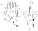
- FIG. 1Ais a view of the controller 100 from the back side of the hand
- FIG. 1Bis a view of the controller 100 seen from the side surface of the thumb side
- FIG. 2is a view of the controller 100 as viewed from the palm side.
- the sensor 1detects information (first information) that senses at least one finger (first finger) included in the detection range of the sensor 1.
- the sensor 1detects depth information indicating a distance (depth) from a finger included in the detection range. More specifically, the sensor 1 detects the depth information of each joint portion included in the at least one finger.
- the sensor 1is a depth sensor, and the sensor 1 detects the depth information of each joint portion.
- the information detected by the sensor 1is not limited to the depth information, and may be any information as long as it is useful for specifying the finger (or the position and posture of each joint included in the finger). For example, an image that does not include a distance (RGB image, black-and-white image, infrared image, etc.
- the measurement marker 14may be a light emitting marker.
- the measurement marker 14may be a two-dimensional marker or a three-dimensional marker. In the case of a two-dimensional marker or a three-dimensional marker, non-light emission or light emission may be detected by an RGB camera or a black-and-white camera, and in the case of a light-emitting marker, detection is possible even in a dark place.
- an infrared cameramay be used to detect a marker that emits infrared rays.
- a contact sensor 25is provided on the back surface of the mounting portion 10 (the surface facing the palm) on the palm side.
- the contact sensor 25is a sensor that detects contact with the palm.
- the contact sensor 25is electrically connected to the main body 11 via wiring provided in the mounting portion 10 (for example, wiring embedded in a belt). By detecting the contact with the palm by the contact sensor 25, it is possible to detect that the user is wearing the controller 100.
- the signal processing circuit 42calculates information (posture information) that identifies the postures of five fingers or at least one finger based on the depth information of the sensor 1. More specifically, the position / posture information that specifies the position / posture of each joint of each finger is calculated. The position / posture information of each joint of each finger calculated from the depth information of the sensor 1 is referred to as position / posture information 1.
- the position / attitude information 1is the position / attitude information of the local coordinate system based on the position of the sensor 1.
- the calculation unit 44determines the position / posture information of each joint of each finger with respect to the main body 11 based on the position / posture information 1 of each joint of each finger and the position / posture information 2 of each joint of each finger. ..
- the position of the main body 11is detected by the head device (or IMU43).
- the position of the main body 11may be treated as the position of the sensor 1 as an example.
- the sensor 1is fixed to the housing 12, and the positional relationship with the housing 12 is constant.
- the sensor 2since the sensor 2 is connected to the sensor 1 (housing 12) via the mounting portion 10, the relative position and orientation of the coordinate system between the sensor 1 and the sensor 2 is undefined.
- Equation (3)can be transformed into equation (4).
- the capacitance detection circuit 45When it is determined that the user has mounted the controller 100, the capacitance detection circuit 45 provides the mounting detection signal to the transmission / reception unit 46. When it is determined that the user does not wear the controller 100, the wearing detection signal is not provided to the transmission / reception unit 46, or the non-wearing detection signal is provided to the transmission / reception unit 46.
- the infrared irradiation unit 301is, for example, an LED (Light Emitting Diode) that emits infrared rays.
- LEDLight Emitting Diode
- the computer 200includes a transmission / reception unit 201, a transmission / reception unit 202, a gesture recognition unit 230, an instruction generation unit 240, and an application unit 250.
- an input unit for inputting data or instructions by the user, an output unit for outputting information to the user, and the likemay be provided.
- the elements 201, 202, 230, 240, and 250are configured by, for example, a hardware circuit, a storage device, and the like.
- the hardware circuitis composed of a processing circuit such as a CPU, DSP, ASIC, FPGA, or a combination thereof.
- [Item 10]The detection device according to any one of items 1 to 9, further comprising a contact sensor for detecting contact between the thumb and the index finger.
- [Item 11]The detection device according to any one of items 7 to 9, further comprising a contact sensor for detecting contact with at least one of the palm and the back of the hand.
- [Item 12]A calculation for calculating the relative position and posture of the first sensor and the second sensor based on the first information and the second information of the joint portion commonly included in the first finger and the second finger.
- the detection device according to item 3comprising a unit.
- [Item 13]The detection device according to item 12, wherein the joint portion commonly included is the terminal segment of the index finger.
Landscapes
- Engineering & Computer Science (AREA)
- General Engineering & Computer Science (AREA)
- Theoretical Computer Science (AREA)
- Physics & Mathematics (AREA)
- General Physics & Mathematics (AREA)
- Human Computer Interaction (AREA)
- User Interface Of Digital Computer (AREA)
Abstract
Description
Translated fromJapanese本開示は、検出装置及び検出方法に関する。This disclosure relates to a detection device and a detection method.
ユーザの手指の姿勢を装置の制御に利用する技術が提案されている。例えば、下記特許文献1には、非接触センサで検出したユーザの手指(例えば人差し指、中指、薬指、小指)の形状に基づき各種の制御を行うことが開示されている。しかしながら、手指の曲げ方によっては、ある手指が別の手指に隠されてしまい、手指の形状を正しく検出できない場合も生じ得る。例えば親指によって人差し指が隠されてしまい、人差し指の形状を正しく検出できなくなる。また手指ごとに接触センサを設ける必要があり、センサ数が多くなる。このため、ユーザが手指を動かしたり、物を掴んだりするのに不便である。A technology that uses the posture of the user's fingers to control the device has been proposed. For example,
本開示は、ユーザの手指の姿勢をより確実に検出する検出装置及び検出方法を提供する。The present disclosure provides a detection device and a detection method for more reliably detecting the posture of a user's finger.
本開示の検出装置は、親指と人差し指との間の空間に配置され、第1検出領域に含まれる手指である第1手指をセンシングした第1情報を検出する第1センサと、手の平に配置され、第2検出領域に含まれる手指である第2手指をセンシングした第2情報を検出する第2センサと、を備える。The detection device of the present disclosure is arranged in the space between the thumb and the index finger, and is arranged on the palm and the first sensor that detects the first information that senses the first finger, which is the finger included in the first detection area. , A second sensor that detects the second information that senses the second finger, which is the finger included in the second detection area, and the like.
本開示の検出方法は、親指と人差し指との間の空間に配置された第1センサによって、前記第1センサの第1検出領域に含まれる手指である第1手指をセンシングした第1情報を検出し、手の平に配置された第2センサによって、前記第2センサの第2検出領域に含まれる手指である第2手指をセンシングした第2情報を検出する。In the detection method of the present disclosure, the first information obtained by sensing the first finger, which is a finger included in the first detection area of the first sensor, is detected by the first sensor arranged in the space between the thumb and the index finger. Then, the second sensor arranged on the palm detects the second information obtained by sensing the second finger, which is the finger included in the second detection area of the second sensor.
以下、図面を参照して、本開示の実施形態について説明する。本開示において示される1以上の実施形態において、各実施形態が含む要素を互いに組み合わせることができ、かつ、当該組み合わせられた結果物も本開示が示す実施形態の一部をなす。Hereinafter, embodiments of the present disclosure will be described with reference to the drawings. In one or more embodiments shown in the present disclosure, the elements included in each embodiment can be combined with each other, and the combined result is also part of the embodiments shown in the present disclosure.
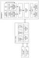
図1及び図2は、本開示の第1実施形態に係る検出装置の一形態であるコントローラ100のブロック図である。図1(A)はコントローラ100を手の甲側から見た図であり、図1(B)はコントローラ100を親指側の側面から見た図である。図2はコントローラ100を手の平側からみた図である。1 and 2 are block diagrams of the
図1及び図2に示すコントローラ100は右手用のコントローラである。コントローラ100がユーザの右手に装着された状態が示されている。左手用のコントローラも、左右の形状の違い等を除き、右手用のコントローラと同様の構成を有する。The
コントローラ100は、手の甲側の本体部11と、手の平側のサブ部21(図2参照)と、装着部10とを備えている。本体部11は、後述する制御装置であるコンピュータ(図9、図10参照)と配線17で接続されており、コンピュータと通信可能である。コンピュータは、コントローラ100と、ユーザの頭部に装着させる頭部装置(図9、図10参照)とを用いてユーザにアプリケーションによるサービスを提供する。ここでは本体部11がコンピュータと有線で通信する構成を説明したが、本体部11がコンピュータと無線で通信する構成も可能である。またコントローラ100が頭部装置と、有線又は無線で通信可能な構成であってもよい。The
装着部10は、本体部11及びサブ部21をユーザの手に装着させる。装着部10は、手の甲と手の平とを少なくとも部分的に覆う被覆部(装着カバー)を含む。被覆部は、一例として、布のような柔らかな素材又は弾力性のある素材によるベルトである。これにより手の大きさ又は形状といった個人差に拘わらず、コントローラ100を手にフィットさせることができる。装着部10は、親指を通過させる開口を備える。ユーザはコントローラ100を手に装着する際、開口に親指をくぐらせることで、コントローラ100を簡単に装着できる。装着部10にファスナー又はボタン等を設け、装着時のフィット状態を調整できるようにしてもよい。The
図1(A)において、本体部11は、手の甲側で装着部10に装着されている。本体部11は、筐体(第1筐体)12と、測定マーカ14と、センサ1(第1センサ)とを含む。In FIG. 1A, the
筐体12は、手の甲側において装着部10の表面に装着(固定)されている。筐体12は、一例として樹脂等の誘電体材料により構成される。ユーザがコントローラ100を装着して、手を広げたとき、筐体12の一部が、人差し指と親指との間の空間に含まれる。筐体12のうち、この空間に含まれる部分を突出部12Aと呼ぶ。The
図2において、突出部12Aの面のうち、手の甲と反対側の面にはセンサ1と測定マーカ14が設けられている。また、図1(A)及び図1(B)に示すように、筐体12の面のうち手の甲と反対側の面及び側面には測定マーカ14が設けられている。図1(B)では親指側の側面に測定マーカ14が設けられているが、他の側面にも測定マーカが設けられていてもよい。In FIG. 2, a
図2においてセンサ1は、センサ1の検出範囲に含まれる少なくとも1つの手指(第1手指)をセンシングした情報(第1情報)を検出する。一例として、センサ1は、検出範囲に含まれる指との距離(デプス)を示すデプス情報を検出する。より詳細には、センサ1は、当該少なくとも1つの手指に含まれる各関節部のデプス情報を検出する。本例では、センサ1はデプスセンサであり、センサ1は各関節部のデプス情報を検出するとする。但し、センサ1が検出する情報は、デプス情報に限定されず、手指(又は手指に含まれる各関節部の位置姿勢)を特定するのに有用な情報であれば、何でもよい。例えば、距離を含まない画像(カメラにより取得されるRGB画像や白黒画像、赤外線画像等)でもよい。画像をパターン認識等で解析することで、手指の姿勢を特定できる場合もあり得る。なお、赤外線画像により手指の姿勢を特定する場合には、センサ1と合わせて赤外線発光素子(例えば940nm波長を有するIRLED等)を配置することで、暗所や直射日光の当たるような明るい場所でも、安定して手指の画像を取得し、その姿勢を特定することができる。発光素子の発光は、カメラ等のセンサ1による画像取得の撮像タイミングに限定して行えばよい。In FIG. 2, the
センサ1として、一例として、ToF(Time of Flight)を用いることができる。その他にもLIDAR(Light Detection and Ranging、Laser Imaging Detection and Ranging)、レーダ、ステレオカメラなどの距離を検出可能なセンサや、単眼カメラ、DVSカメラ、赤外線カメラなど、任意のセンサを用いることができる。また、センサ1は例えば水平画角150度を越えるような広いセンシングエリアを必要とすることが想定されるが、その要件を満たすために、単一のセンサの使用に替えて、同じ位置に2個や3個などの複数のセンサを角度差を付けて並べて配置する実施も考えられる。As the
センサ1は、ユーザが手を広げた状態において、人差し指と親指との間の空間に含まれる。より具体的には、センサ1は、人差し指の根本と、親指との間の空間に含まれる。The
測定マーカ14は、ユーザの頭部に設置する頭部装置から本体部11の位置及び姿勢(位置姿勢)を検出するための部材である。測定マーカ14として、頭部装置から位置姿勢を算出する手法に応じて適切な部材を用いることができる。一例として、測定マーカ14として、光学センシング用の反射マーカを用いることができる。具体的には、測定マーカ14は赤外線を反射する反射部材(例えば再帰性反射部材)である。この場合、頭部装置では赤外線を照射し、測定マーカ14からの反射光を検出することで、頭部装置の座標系を基準とした、本体部11の位置姿勢を算出できる。頭部装置から画像解析により位置姿勢を算出する場合は、画像解析で検出が容易な色又は形状等を有する部材を用いてもよい。また測定マーカ14は発光マーカでもよい。また、測定マーカ14は2次元マーカでもよいし、3次元マーカでもよい。2次元マーカあるいは3次元マーカの場合、RGBカメラや白黒カメラで非発光あるいは発光を検出するのでもよく、発光マーカの場合は暗所でも検出が可能となる。あるいは、赤外線カメラによって、赤外線発光するマーカを検出するのでもよい。赤外線カメラを使用する場合、カメラに使用するバンドパスフィルタとマーカ発光用のLEDの波長を940nm付近とすることで、取得画像に太陽光等の外光の影響が出にくくなり、画像処理によるマーカ検出が容易となる。The
図1(A)において、手の甲側における装着部10の裏面(手の甲と対向する面)には、接触センサ15が設けられている。接触センサ15は、手との接触を検知するセンサである。接触センサ15は装着部10内に設けられた配線(例えばベルトに埋め込まれた配線)を介して、本体部11に電気的に接続されている。接触センサ15により手の甲との接触を検知することで、ユーザがコントローラ100を装着していることを検出できる。In FIG. 1A, a
接触センサ15の一例として、静電容量センサを用いることができる。例えば、静電容量センサは電極と誘電体とを含む。コントローラ100の装着時に、電極と手の甲との間に当該誘電体が挟まれ、このときの静電容量の変化を検出することで、手の平との接触を検知できる。As an example of the
接触センサ15を、筐体12の表面、より具体的には、筐体12の面のうち、手の甲側の面に設けることも可能である。この場合、装着部10に開口を設け、開口を介して接触センサ15が手の甲に直接、接触可能にしてもよい。あるいは、接触センサ15が、筐体12と装着部10との間に挟まれてもよい。この場合、接触センサ15は、手の甲との間接的な接触を検知できる。It is also possible to provide the
また、接触センサを用いた別のセンシングの例として、人差し指先と親指先の接触を検出してもよい。この場合、例えば、装着部10などに手の甲、手の平、あるいは指の根本などに直接接触するような形で電極を2つ配置する。2つの電極の内の片方は回路のGNDに接続され、もう片方には交流電圧等が印加される。そして、指先同士の接触に伴う静電容量変化及び抵抗値の少なくとも一方の変化を、この電極の電圧値の変化等により検出する。これにより人差し指先と親指先の接触を検出する。人差し指先と親指先を接触させる動作に対するジェスチャコマンドの検出が可能となる。Further, as another example of sensing using the contact sensor, the contact between the index finger tip and the thumb tip may be detected. In this case, for example, two electrodes are arranged on the mounting
図2において、サブ部21は、装着部10の手の平側に装着されている。サブ部21は、一例として、ユーザがコントローラ100を手に装着した際に、小指球を含む領域又は鉤骨上の領域上に位置する。ただし、サブ部21が、当該領域以外の領域に設けられてもよい。サブ部21は、筐体(第2筐体)22と、測定マーカ24と、センサ(第2センサ)2とを含む。In FIG. 2, the
筐体22は、手の平側において装着部10の表面に装着(固定)されている。筐体22は、一例として樹脂等の誘電体材料により構成される。筐体22の面のうち、手の平と反対側の面には、センサ2と測定マーカ24とが設けられている。The
センサ2は、センサ2の検出範囲に含まれる少なくとも1つの手指(第2手指)をセンシングした情報(第2情報)を検出する。一例として、センサ2は、検出範囲に含まれる指との距離(デプス)を示すデプス情報を検出する。より詳細には、センサ2は、当該少なくとも1つの手指に含まれる各関節部のデプス情報を検出する。本例では、センサ2はデプスセンサであり、センサ2は各関節部のデプス情報を検出するとする。但し、センサ2が検出する情報は、デプス情報に限定されず、手指の姿勢(又は手指に含まれる各関節部の位置姿勢)を特定するのに有用な情報であれば、何でもよい。例えば、距離を含まない画像(カメラにより取得されるRGB画像や白黒画像、赤外線画像等)でもよい。画像をパターン認識等で解析することで、手指の姿勢を特定できる場合もあり得る。なお、赤外線画像により手指の姿勢を特定する場合には、センサ2と合わせて赤外線発光素子(例えば940nm波長を有するIRLED等)を配置することで、暗所や直射日光の当たるような明るい場所でも、安定して手指の画像を取得し、その姿勢を特定することができる。発光素子の発光は、カメラ等のセンサ2による画像取得の撮像タイミングに限定して行えばよい。センサ2は、装着部10内に設けられた配線(例えばベルトに埋め込まれた配線)を介して、本体部11に電気的に接続されている。The
センサ2は、一例として小指球を含む領域(又は鉤骨上の領域)上に位置する。これによりユーザのすべての手指または多くの手指のデプス情報を、各手指の姿勢にかかわらず、効果的に検出することが可能となる。The
センサ2の例として、ToF(Time of Flight)を用いることができる。その他にもLIDAR(Light Detection and Ranging、Laser Imaging Detection and Ranging)、レーダ、ステレオカメラなどの距離を検出可能なセンサや、単眼カメラ、DVSカメラ、赤外線カメラなど、任意のセンサを用いることができる。また、センサ2は例えば水平画角100度を越えるような広いセンシングエリアを必要とすることが想定されるが、その要件を満たすために、単一のセンサの使用に替えて、同じ位置に2個や3個などの複数のセンサを角度差を付けて並べて配置する実施も考えられる。ToF (Time of Flight) can be used as an example of the
測定マーカ24は、ユーザの頭部に設置する頭部装置からサブ部21の位置姿勢(手の位置姿勢)を検出するための部材である。測定マーカ24として、光学センシング用の反射マーカを用いることができる。測定マーカ24の構成例は、測定マーカ14と同様でよい。The
手の平側において装着部10の裏面(手の平と対向する面)には、接触センサ25が設けられている。接触センサ25は、手の平との接触を検知するセンサである。接触センサ25は装着部10内に設けられた配線(例えばベルトに埋め込まれた配線)を介して、本体部11に電気的に接続されている。接触センサ25により手の平との接触を検知することで、ユーザがコントローラ100を装着していることを検出できる。A
接触センサ25の構成は、接触センサ15と同様でよい。例えば、接触センサ25として、静電容量センサを用いることができる。静電容量センサは電極と誘電体とを含む。コントローラ100の装着時に電極と手の平との間に当該誘電体が挟まれ、このときの静電容量の変化を検出することで、手の平との接触を検知できる。静電容量センサ以外にも、手の平に接触したときに圧力の変化を検出する圧力センサなど、他の方式のセンサを用いてもよい。The configuration of the
装着部10に開口を設け、開口を介して接触センサ25が手の平に直接、接触可能にしてもよい。また接触センサ25が、筐体22と装着部10との間に挟まれる構成も可能である。この場合、接触センサ25は、装着部10を介して手の平との間接的な接触を検知できる。An opening may be provided in the mounting
また、接触センサ25を用いた別のセンシングの例として、接触センサ15の説明で記載したように、装着部10などに手の平などに直接接触するような形で電極を2つ配置することで、人差し指先と親指先の接触を検出してもよい。人差し指先と親指先の接触を検出することで、人差し指先と親指先を接触させる動作に対するジェスチャコマンドの検出が可能となる。Further, as another example of sensing using the
図3は、手の甲側のセンサ1及び手の平側のセンサ2の検出範囲の例を模式的に示す。センサ1の検出範囲13A及びセンサ2の検出範囲23Aは、概ね四角錐の形状を有する。但し、検出範囲13A及び検出範囲23Aの形状は、円錐など他の形状でもよい。検出範囲13A及び検出範囲23Aで検出可能な手指(例えば各手指に含まれる各関節部)は、手指の姿勢(形状)に応じて変わり得る。FIG. 3 schematically shows an example of the detection range of the
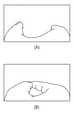
図4(A)及び図4(B)は、手の甲側のセンサ1により検出されたデプス情報の例を示す。図4(A)及び図4(B)のデプス情報は、各画素にデプス値を格納したデプス画像である。図4(A)は、親指の先端と、人差し指の先端との間を広げた状態で撮像されたデプス画像の例である。図4(B)は、親指の先端と、人差し指の先端とを接触させた状態で撮像されたデプス画像の例である。図4(A)及び図4(B)のいずれにおいても親指と人差し指が他の指に遮蔽されることなく検出(撮像)されている。一方、中指、薬指及び小指のデプス情報は、図4(A)及び図4(B)のいずれにおいても検出されていない。すなわち、図4(A)及び図4(B)のデプス画像を撮像したときの各手指の姿勢(形状)では、中指、薬指及び小指のデプス情報を検出できない。なお、各手指の姿勢によっては、中指、薬指及び小指のうちの少なくとも1つの手指のデプス情報(例えば、手指に含まれる少なくとも1つの関節部のデプス情報)が、センサ1で検出される場合もある。4 (A) and 4 (B) show an example of the depth information detected by the
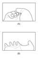
図5(A)及び図5(B)は、手の平側のセンサ2により検出されたデプス情報の例を示す。図5(A)及び図5(B)のデプス情報は、各画素にデプス値を格納したデプス画像である。図5(A)は、手を握った状態で撮像されたデプス画像の例である。図5(B)は、手を広げた状態で撮像されたデプス画像の例である。図5(B)では全ての手指のデプス情報(各手指に含まれる少なくとも1つの関節部のデプス情報)が検出されている。図5(A)では人差し指の大部分が親指によって遮蔽されている。図5(A)のデプス情報からでは、人差し指の姿勢(例えば人差し指の各節の姿勢)を高精度の認識することは困難な場合もある。5 (A) and 5 (B) show examples of depth information detected by the
手の甲側の筐体12内には、IMU(Inertial Measurement Unit)等のセンサ、振動子48等のアクチュエータ、処理システムが格納されている。処理システムは、センサ1、センサ2、接触センサ15、接触センサ25、IMU等により検出された信号及びコンピュータから受信する信号に基づいた処理を行う。筐体12には、バッテリが格納されていてもよい。この場合、バッテリは、各種センサ及び筐体12内の各要素に対する動作電圧を供給する。動作電圧は、本体部11及びコンピュータ間の配線17(図1参照)を介して供給されてもよい。本実施形態では、動作電圧は、配線17を介してコンピュータから供給される場合を想定する。A sensor such as an IMU (Inertial Measurement Unit), an actuator such as a
図6は、図1及び図2に示したコントローラ100の機能ブロック図である。コントローラ100は、センサ1、センサ2、接触センサ15、接触センサ25、測定マーカ14、処理システム41、IMU43、及び振動子48を備えている。処理システム41、IMU43及び振動子48は筐体12内に配置されている。FIG. 6 is a functional block diagram of the
処理システム41は、処理部49(信号処理回路42、演算部44)、静電容量検出回路45、送受信部46、及び増幅器47を備えている。処理システム41は、ハードウェア回路及び記憶装置等により構成される。ハードウェア回路は、CPU、DSP(Digital Signal Processor)、ASIC(Application Specific Integrated Circuit)、FPGA(Field-Programmable Gate Array)、又はこれらの組み合わせ等の処理回路により構成される。記憶装置は、揮発性メモリ、書き換え可能不揮発性メモリ、ROM(Read On Memory)、磁気記憶メモリ、ハードディスク、光学ディスクなど、任意の記録媒体により構成される。処理システムは、一例として1チップ又は複数のチップにより構成される。CPU等のプロセッサがコンピュータプログラムである情報処理プログラムを実行することにより、要素42、44、45、46、47、49のうちの少なくとも1つの機能が実現されてもよい。The processing system 41 includes a processing unit 49 (
信号処理回路42は、センサ1から検出信号(デプス情報)を取得する。信号処理回路42は、センサ2から検出信号(デプス情報)を取得する。信号処理回路42は、センサ1から第1情報の一例であるデプス情報を取得する第1取得部と、センサ2から第2情報の一例であるデプス情報を取得する第2取得部とを備えている。The
信号処理回路42は、センサ1のデプス情報に基づき、5つの手指又は少なくとも1つの手指の姿勢を特定する情報(姿勢情報)を算出する。より詳細には、各手指の各関節部の位置姿勢を特定する位置姿勢情報を算出する。センサ1のデプス情報から算出された各手指の各関節部の位置姿勢情報を位置姿勢情報1と記載する。位置姿勢情報1は、センサ1の位置を基準とするローカル座標系の位置姿勢情報である。The
信号処理回路42は、センサ2のデプス情報に基づき、5つの手指又は少なくとも1つの手指の姿勢を特定する情報(姿勢情報)を算出する。より詳細には、各手指の各関節部の位置姿勢を特定する位置姿勢情報を算出する。センサ2のデプス情報から算出された各手指の各関節部の位置姿勢情報を、位置姿勢情報2と記載する。位置姿勢情報2は、センサ2の位置を基準とするローカル座標系の位置姿勢情報である。The
センサ1のデプス情報又はセンサ2のデプス情報から各手指の各関節部の位置姿勢情報を算出するために、機械学習により生成したモデルを用いることができる。例えば、デプス情報から各手指の各関節部の位置姿勢情報を回帰する回帰モデルを用いることができる。回帰モデルの例として、ニューラルネットワーク(例えばディープニューラルネットワーク:DNN)、非線形回帰モデル、SVM(Support Vector Machine)などがある。A model generated by machine learning can be used to calculate the position / posture information of each joint of each finger from the depth information of the
信号処理回路42は、各手指の各関節部の位置姿勢情報1を演算部44に提供する。信号処理回路42は、各手指の各関節部の位置姿勢情報2を演算部44に提供する。なお、位置姿勢を算出できなかった手指の関節部が存在する場合、算出できなかったことを示す情報を位置姿勢情報1又は位置姿勢情報2に含めればよい。なお、センサ1及びセンサ2のデプス情報のいずれにも、ある手指のある関節部のデプスが含まれていない場合であっても、ニューラルネットターク等のモデルにより当該関節部の位置姿勢が推定される場合もあり得る。The
IMU(Inertial Measurement Unit)43は、一例としてジャイロセンサと加速度センサとを含む。ジャイロセンサは、基準軸に対する3軸の角速度を検出する。加速度センサは、基準軸に対する3軸の加速度を検出する。IMU43は、3軸の磁気センサを含んでもよい。The IMU (Inertial Measurement Unit) 43 includes a gyro sensor and an acceleration sensor as an example. The gyro sensor detects the angular velocities of the three axes with respect to the reference axis. The accelerometer detects the acceleration of three axes with respect to the reference axis. The IMU43 may include a 3-axis magnetic sensor.
演算部44は、IMU43の検出信号に基づき、本体部11の位置(ローカル位置)と、姿勢(方向)とを算出する。すなわち、ユーザの手の位置姿勢を算出する。また、演算部44は、本体部11の移動距離及び速度の少なくとも一方を算出してもよい。The
演算部44は、各手指の各関節部の位置姿勢情報1と、各手指の各関節部の位置姿勢情報2とに基づき、本体部11に対する各手指の各関節部の位置姿勢情報を決定する。本体部11の位置は頭部装置(又はIMU43)により検出される。本体部11の位置は一例としてセンサ1の位置として扱ってもよい。センサ1は筐体12に固定されており、筐体12との位置関係は一定である。一方、センサ2は装着部10を介してセンサ1(筐体12)と接続されるため、センサ1とセンサ2との座標系の相対的な位置姿勢は不定である。具体的には、ユーザの手の大きさ、形状の違いや、ベルトの装着位置の違いにより、装着時のベルトの形状が変化する。この結果として、センサ1及びセンサ2間の座標系の相対的な位置姿勢が変化する。そこで、センサ1及びセンサ2間の座標系の相対的な位置姿勢を算出し、算出した相対的な位置姿勢に基づき、位置姿勢情報2をセンサ1の座標系に変換する。変換の方法を以下に説明する。The
センサ1とセンサ2の座標系の相対的な位置姿勢を求めることは、回転行列Rと並進ベクトルTを用いて、センサ2の座標系の3次元ベクトルから、センサ1の座標系の3次元ベクトルに変換する式を求めることと同義と捉えられる。To obtain the relative position and orientation of the coordinate system of the
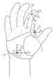
センサ1の検出範囲とセンサ2の検出範囲とは互いに重複するため、センサ1とセンサ2との両方から検出される関節部(対象となる関節部)がある。例えば、人差し指の先端の節(末節)については、センサ1、2の両方から検出されることになる場合が多い。Since the detection range of the
センサ1の座標系を座標系1、センサ2の座標系を座標系2,人差し指の末節の座標系を座標系3とする。The coordinate system of the
図8に、センサ1の座標系1、センサ2の座標系2、及び、人差し指の末節51の座標系3の例を示す。なお図8には人差し指の末節51以外の関節部も丸の記号で示されている。FIG. 8 shows an example of the coordinate
センサ1の座標系1と、人差し指の末節の座標系3との関係は、式(1)により表される。
センサ2の座標系2と、人差し指の末節の座標系3との関係は、式(2)により表される。
式(1)と式(2)から式(3)が得られる。
式(3)を式(4)に変形することができる。
式(4)のRa-1・RbをR、Ra-1・(Tb-Ta)をTとすると、以下の式(5)が得られる。
演算部44は、式(5)の関係に基づき、位置姿勢情報2を、センサ1の座標系1に変換する。そして、変換後の位置姿勢情報2と、位置姿勢情報1とから、各手指(例えば、センサ1で検出された手指とセンサ2で検出された手指とに含まれる手指)の各関節部の位置姿勢情報を決定する。一例として、位置姿勢情報1及び変換後の位置姿勢情報2の一方にのみ含まれる手指の関節部については、当該一方に含まれる手指の関節部の位置姿勢情報を用いる。両方に含まれる手指の関節部については両方の位置姿勢情報の平均を用いてもよいし、いずれか一方を採用してもよい。演算部44は各手指の各関節部の位置姿勢情報を送受信部46に提供する。ここでは演算部44が位置姿勢情報1及び位置姿勢情報2から各手指の各関節部の位置姿勢情報を決定したが、位置姿勢情報1及び位置姿勢情報2をコンピュータ(図9、図10参照)に送信し、コンピュータ側で各手指の各関節部の位置姿勢情報を決定してもよい。The
センサ1とセンサ2の座標系の相対的な位置姿勢は、手指の動きに伴って時々刻々と変化するため、上記の式(1)~(5)のような演算によりパラメータを求める処理を、一定期間毎に行ってもよい。Since the relative positions and postures of the coordinate systems of the
図7は、一定時間毎にセンサ1とセンサ2の座標系の相対的な位置姿勢を算出する動作の一例を示すフローチャートである。まず、センサ1とセンサ2の座標系の相対的な位置姿勢に関するパラメータTp、Rpとしてデフォルト値のTd、Rdを設定する(S101)。センサ1およびセンサ2の検出信号(デプス情報)に基づき、各指の各関節部の位置姿勢を検出する(S102)。センサ1から検出された各関節部の位置姿勢に、対象となる関節部(例えば、人差し指の末節)の位置姿勢が含まれるかを判断する(S103)。対象となる関節部の位置姿勢が含まれる場合に(YES)、センサ2から検出された各関節部の位置姿勢に、対象となる関節部の位置姿勢(例えば、人差し指の末節)が含まれるかを判断する(S104)。対象となる関節部の位置姿勢が含まれる場合に(YES)、式(5)により求まるT,RによってパラメータTp,Rpを更新する(S105)。この後、ステップS102に戻る。ステップS103又はステップS104で対象となる関節部の位置姿勢が含まれないと判断された場合は、パラメータTp,Rpの更新を行わずに、ステップS102に戻る。FIG. 7 is a flowchart showing an example of an operation of calculating the relative position / orientation of the coordinate system of the
コントローラ100の使用中における上記相対的な位置姿勢の変化量は、ユーザの手の形状、大きさ、コントローラ100の装着位置の違い等を起因とする上記変化量に比べると通常は小さくなる。そのため、ユーザがコントローラ100を一旦装着した後は、相対的な位置姿勢は一定とみなすことも可能である。この場合には、コントローラ100の装着後にユーザに対して、センサ1及びセンサ2が対象となる関節部(例えば、人差し指の末節)を共通に検出可能な姿勢を取らせる。例えば、初期設定モード時に音声メッセージ又は頭部装置で提供する画像などを介して、ユーザに当該姿勢を取らせるメッセージを提示してもよい。ユーザが当該姿勢を取っている間に、センサ1及びセンサ2の座標系の相対的な位置姿勢を算出する処理を行う。これによればセンサ1、2の両方で対象となる関節部を確実に検出することができるため、検出ロスが無く、効率的である。
図2の構成では、センサ2をセンサ1とは別の筐体(構造物)に設けたが、センサ2をセンサ1と同じ筐体に設けてもよい。これにより、センサ2の位置姿勢が本体11に対して変化することを抑制できる。具体的には、例えば、図1の本体11の筐体を小指側に手の甲から手の平にかけて沿うように延長された構造とし、図2に示す位置にセンサ2を配置する構成が考えられる。センサ2がセンサ1と同じ筐体上に配置されることによって、センサ1とセンサ2の間の相対位置姿勢の変化を抑えることができる。これにより、手指関節のセンシング誤算の影響を受ける式(5)を用いた演算の必要がなくなるため、手指の各関節の位置姿勢の検出精度を向上させることが可能となる。The amount of change in the relative position / posture during use of the
In the configuration of FIG. 2, the
図6において、静電容量検出回路45は、接触センサ15から検出信号を取得する。また静電容量検出回路45は、接触センサ25から検出信号を取得する。静電容量検出回路45は、接触センサ15及び接触センサ25の検出信号の少なくとも一方に基づき、ユーザがコントローラ100を装着したかを判断する。一例として、静電容量の変化量が接触センサ15及び接触センサ25の両方、もしくはいずれか一方で閾値以上になった場合は、ユーザがコントローラ100を装着したと判断する。あるいは、静電容量の値が接触センサ15及び接触センサ25の両方、もしくはいずれか一方も閾値以上になった場合は、ユーザがコントローラ100を装着したと判断する。静電容量検出回路45は、ユーザがコントローラ100を装着したと判断した場合は、装着検出信号を送受信部46に提供する。ユーザがコントローラ100を装着していないと判断した場合、装着検出信号を送受信部46に提供しない、あるいは非装着検出信号を送受信部46に提供する。In FIG. 6, the
送受信部46は、演算部44から提供された本体部11の位置姿勢情報(手の位置姿勢情報)をコンピュータ(図9、図10参照)に送信する。送受信部46は、演算部44から提供された各手指の姿勢を特定する情報(例えば各手指の各関節部の位置姿勢情報)をコンピュータに送信する。送受信部46は、演算部44から提供された装着検出信号をコンピュータに送信する。送受信部46は、演算部44から提供された非装着検出信号をコンピュータに送信する。送受信部46は、コンピュータから振動子48用の制御信号を受信した場合、制御信号を増幅器47に提供する。The transmission / reception unit 46 transmits the position / posture information (position / posture information of the hand) of the
増幅器47は、送受信部46から提供された振動子48用の制御信号を増幅し、増幅された制御信号を振動子48に提供する。The
振動子48は、入力された信号に基づき振動するバイブレータである。振動子48は、増幅器47から提供された制御信号に基づき振動する。振動子48の振動は、コントローラ100を装着したユーザの手に触覚として知覚される。これによりユーザは手指及び手を使って生成したジェスチャ(ハンドサイン)として行った指示に対応するフィードバックを触覚により取得できる。The
図9は、右手用のコントローラ100と、左手用のコントローラ100と、コンピュータ200と、頭部装置300とを備えたコンピュータシステムのブロック図である。
図10は、図9のコンピュータシステムの一構成例において右手用及び左手用のコントローラ100と、頭部装置300とをユーザが装着した例を示す。FIG. 9 is a block diagram of a computer system including a
FIG. 10 shows an example in which a user wears a right-handed and left-
図10において、コンピュータ200は、右手用及び左手用のコントローラ100は有線により接続されている。コンピュータ200は頭部装置300と有線により接続されている。右手用及び左手用のコントローラ100の配線は、頭部装置300の後部において、頭部装置300の配線と1つにまとめられて、コンピュータ200に接続されている。但し、コンピュータ200と、右手用及び左手用のコントローラ100とが無線により接続されていてもよい。コンピュータ200と頭部装置300とが無線により接続されていてもよい。In FIG. 10, in the
右手用のコントローラ100及び左手用のコントローラ100は、上述の図6に示した構成を有する。以下の説明において、コントローラ100を記載するとき、左手用及び右手用のいずれのコントローラ100、又は両方のコントローラ100を指してもよい。また、手と記載するときは、左手、右手、又はこれらの両方を指してもよい。The right-
図9のコンピュータシステムにおいて、現実空間における座標系である実座標系が基準点を原点として予め設定されている。基準点は、現実空間における任意の位置又は所定の位置でもよいし、頭部装置300に含まれる任意の位置又は所定の位置でもよい。In the computer system of FIG. 9, the actual coordinate system, which is the coordinate system in the real space, is preset with the reference point as the origin. The reference point may be an arbitrary position or a predetermined position in the real space, or may be an arbitrary position or a predetermined position included in the head device 300.
頭部装置300は、赤外線照射部301、赤外線カメラ部302、右左手位置姿勢認識部303、IMU311、RGBカメラ部312、頭部位置姿勢認識部313、3次元情報統合部320、送受信部330、ディスプレイドライバ340、左目用の表示部351及び右目用の表示部352を備える。要素303、313、320、330、340は、ハードウェア回路及び記憶装置等により構成される。ハードウェア回路は、CPU、DSP、ASIC、FPGA、又はこれらの組み合わせ等の処理回路により構成される。記憶装置は、揮発性メモリ、書き換え可能不揮発性メモリ、ROM、磁気記憶メモリ、ハードディスク、光学ディスクなど、任意の記録媒体により構成される。CPU等のプロセッサがコンピュータプログラムである情報処理プログラムを実行することにより、要素303、313、320、330、340のうちの少なくとも1つの機能が実現されてもよい。The head device 300 includes an
頭部装置300は、ユーザの頭部に装着され、動作中に左目用の表示部351及び右目用の表示部352を介して、ユーザに情報を提供する装置である。本実施形態では、頭部装置300は、RGBカメラ部312を介して得られる現実世界の画像に、仮想空間を構成する画像の一部を合成した視界画像を出力する拡張現実(AR:Augmented Reality)グラスである場合を想定する。The head device 300 is a device that is attached to the user's head and provides information to the user via the display unit 351 for the left eye and the display unit 352 for the right eye during operation. In the present embodiment, the head device 300 outputs an augmented reality (AR: Augmented Reality) that outputs a field image obtained by synthesizing a part of an image constituting a virtual space with an image of the real world obtained via the RGB camera unit 312. ) Suppose it is a glass.
但し、頭部装置300は、右目用の画像および左目用の画像を非透過型の表示部351、352にそれぞれ表示し、ユーザの両目の視差に基づき当該画像を3次元画像として認識させるVR(Virtual Reality)グラスでもよい。また頭部装置300は、非透過型の表示部351、352にデジタル情報を提示するスマートグラスでもよい。表示部351、352は、例えば液晶ディスプレイや有機ELモニタなどの表示装置である。However, the head device 300 displays an image for the right eye and an image for the left eye on the non-transparent display units 351 and 352, respectively, and recognizes the image as a three-dimensional image based on the parallax of both eyes of the user (VR). Virtual Reality) Glass may be used. Further, the head device 300 may be a smart glass that presents digital information to the non-transparent display units 351 and 352. The display units 351 and 352 are display devices such as a liquid crystal display and an organic EL monitor.
頭部装置300において、赤外線照射部301及び赤外線カメラ部302はそれぞれ2つ設けられる(図10参照)。In the head device 300, two
赤外線照射部301は、例えば、赤外線を発するLED(Light Emitting Diode)である。The
2つの赤外線カメラ部302は、少なくとも一方の赤外線照射部301により照射され、コントローラ100の測定マーカ14で反射された赤外線を読み取る。赤外線カメラ部302は、読み取った赤外線に基づき、赤外線画像を生成する。右左手位置姿勢認識部303は、2つの赤外線カメラ部302と対象の手(本体部11)の測定マーカ14とによる三角測量で、手の位置又は位置姿勢を算出する。手本体の測定マーカ14の配置を左右の手で異ならせることで、右手と左手との判別が可能である。赤外線を用いるため、屋外などでも測定マーカ14からの反射を得ることができる。また赤外線照射部301を複数設けることで手の検出範囲を広くできる。また、他の動作例として、2つの赤外線照射部301をそれぞれ右手用及び左手用とし、2つの赤外線カメラ部302をそれぞれ右手用及び左手用とする。右手(又は左手)の赤外線カメラ部302は、右手(又は左手)に対応する赤外線照射部301の照射により得られた赤外線画像を解析することで、右手(又は左手)の位置姿勢を認識してもよい。The two
IMU311は、一例としてジャイロセンサと加速度センサとを含む。IMU311の構成は、前述したコントローラ100におけるIMUと同様である。IMU311 includes a gyro sensor and an acceleration sensor as an example. The configuration of the IMU311 is the same as that of the IMU in the
RGBカメラ部312は、一定時間毎に現実世界の空間を撮像し、RGBの画像データを取得する。RGBカメラ部312は、例えば、頭部装置300の筐体の前方に設けられている。The RGB camera unit 312 captures an image of the real world space at regular time intervals and acquires RGB image data. The RGB camera unit 312 is provided, for example, in front of the housing of the head device 300.
頭部位置姿勢認識部313は、IMU311の検出信号に基づき頭部(頭部装置300)の位置姿勢を認識する。頭部位置姿勢認識部313は、認識した位置姿勢を基準とした座標系を、現実空間の座標系とし、RGBカメラ212の画像を、カメラ座標系から現実空間の座標系に変換する。The head position / posture recognition unit 313 recognizes the position / posture of the head (head device 300) based on the detection signal of the IMU311. The head position / posture recognition unit 313 uses the coordinate system based on the recognized position / posture as the coordinate system in the real space, and converts the image of the RGB camera 212 from the camera coordinate system to the coordinate system in the real space.
3次元情報統合部320は、現実空間の変換後の画像と、コンピュータ200から提供される情報(例えば現実空間の画像に重ねて表示する仮想画像等)とに基づき統合処理を行い、ユーザに提示する3次元の画像情報を左目用及び右目用に生成する。統合処理において、右左手位置姿勢認識部303によって得られた左右の手の位置又は位置姿勢を利用してもよい。例えばユーザの手が存在する位置に、手を模した仮想画像を統合してもよい。手を模した仮想画像は、コンピュータ200から提供される情報に含まれていてもよいし、あらかじめ頭部装置300のメモリ装置に格納されており、メモリ装置から仮想画像を読み出してもよい。手の姿勢に応じて仮想画像の手の姿勢を変えてもよい。この場合、姿勢に応じた手の仮想画像が複数用意されていてもよいし、姿勢の変更を計算し、レンダリングしてもよい。The three-dimensional
送受信部330は、右左手位置姿勢認識部303によって取得された左右の手の位置又は位置姿勢情報をコンピュータ200に送信する。また、送受信部330は、3次元情報統合部320により生成された画像情報をディスプレイドライバ340に提供する。送受信部330は、3次元情報統合部320により生成された画像情報をコンピュータ200に送信してもよい。The transmission /
ディスプレイドライバ340は、左目用の画像情報に基づき、左目用の表示部351に画像を表示するための駆動信号を生成する。ディスプレイドライバ340は、右目用の画像情報に基づき、右目用の表示部352に画像を表示するための駆動信号を生成する。ディスプレイドライバ340は、これらの生成した駆動信号を、左目用の表示部351及び右目用の表示部352に提供する。The display driver 340 generates a drive signal for displaying an image on the display unit 351 for the left eye based on the image information for the left eye. The display driver 340 generates a drive signal for displaying an image on the display unit 352 for the right eye based on the image information for the right eye. The display driver 340 provides these generated drive signals to the display unit 351 for the left eye and the display unit 352 for the right eye.
左目用の表示部351及び右目用の表示部352は、ディスプレイドライバ340から提供された駆動信号に基づき、画面に画像を表示する。左目用の表示部351及び右目用の表示部352に表示された画像は、頭部装置300を装着したユーザに視認される。The display unit 351 for the left eye and the display unit 352 for the right eye display an image on the screen based on the drive signal provided by the display driver 340. The images displayed on the display unit 351 for the left eye and the display unit 352 for the right eye are visually recognized by the user wearing the head device 300.
コンピュータ200は、パーソナルコンピュータ(デスクトップ型、ノート型)、スマートフォン等の移動体端末、タブレット装置などの情報機器端末である。コンピュータ200は頭部装置300の外部に設けられる構成が示されているが、コンピュータ200と頭部装置300とが一体に構成されていてもよい。例えば、コンピュータ200は頭部装置300に内蔵されていてもよい。The
コンピュータ200は、送受信部201、送受信部202、ジェスチャ認識部230、命令生成部240、及びアプリケーション部250を備えている。その他、ユーザがデータ又は指示等を入力する入力部、ユーザに情報を出力する出力部等が備えられていてもよい。要素201、202、230、240、250は、一例として、ハードウェア回路及び記憶装置等により構成される。ハードウェア回路は、CPU、DSP、ASIC、FPGA、又はこれらの組み合わせ等の処理回路により構成される。記憶装置は、揮発性メモリ、書き換え可能不揮発性メモリ、ROM、磁気記憶メモリ、ハードディスク、光学ディスクなど、任意の記録媒体により構成される。CPU等のプロセッサがコンピュータプログラムである情報処理プログラムを実行することにより、要素201、202、230、240、250のうちの少なくとも1つの機能が実現されてもよい。コンピュータ200は単一のコンピュータにより構成されてもよいし、相互に接続された複数のコンピュータ装置からなるシステムとして構成されてもよい。コンピュータ200はクラウド等の広域ネットワークにサーバとして存在してもよい。The
送受信部201はコントローラ100との間で所定の通信方式に従って信号を送受信する。送受信部202は頭部装置300との間で所定の通信方式に従って信号を送受信する。各所定の通信方式は、専用の通信方式、USB(Universal Serial Bus)等のシリアル通信、無線LAN(Local Area Network)、ブルートゥース、赤外線通信など、任意の方式を用いることができる。The transmission /
コンピュータ200は、送受信部201を介して、コントローラ100からユーザの手指の姿勢又は動きに関する情報として、各手指の姿勢又は動きを特定する情報(各手指の各関節部の位置姿勢情報又は当該位置姿勢情報の時系列データ)を取得する。またコンピュータ200は、送受信部202を介して、頭部装置300から現実空間の座標系における手の位置又は位置姿勢の情報又はその時系列データを取得する。コントローラ100の本体部11が赤外線照射部301の照射範囲から外れるなどの理由で、頭部装置300から手の位置又は位置姿勢の情報を取得できなくなる場合もあり得る。この場合、コンピュータ200は、コントローラ100から送受信部201を介して取得する手(本体部11)の位置又は位置姿勢の情報に基づき、現実空間の座標系における手(本体部11)の位置又は位置姿勢を把握してもよい。より詳細には、頭部装置300から受信した最新の位置情報からの位置の変化量を、コントローラ100から受信する位置情報に基づき更新することで、現実空間の座標系における手(本体部11)の位置を特定する。手(本体部11)の姿勢は、コントローラ100から受信する姿勢情報を用いて特定する。The
ジェスチャ認識部230は、各手指の各関節部の位置姿勢情報と、手の位置又は位置姿勢情報とに基づき、ユーザのジェスチャ(ハンドサイン)を認識する。手指の各関節部の位置姿勢から、手指の姿勢(形状)が特定可能である。また各手指について複数の時刻分の位置姿勢を特定すれば、各手指の動きが特定可能である。The gesture recognition unit 230 recognizes the user's gesture (hand sign) based on the position / posture information of each joint of each finger and the position or position / posture information of the hand. The posture (shape) of the fingers can be specified from the position and posture of each joint of the fingers. Further, if the position and posture for a plurality of times are specified for each finger, the movement of each finger can be specified.
命令生成部240は、認識されたハンドサインに応じて、アプリケーションに対する操作命令を生成する。例えば、ジェスチャ認識部230は、各手指の姿勢(形状)と、手の位置姿勢とに基づき、ユーザのハンドサインを識別する。具体的には、各手指の姿勢と、手の位置又は位置姿勢と、ハンドサインとを対応付けたテーブルを用意しておき、テーブルから、該当するハンドサインを特定する。手指の姿勢(形状)と、手の位置又は位置姿勢との組み合わせ、又は、当該組み合わせの時系列データは、指し示す、押す、開ける、掴む、回す、投げるなどの様々なアクションのハンドサインとして認識できる。The instruction generation unit 240 generates an operation instruction for the application according to the recognized hand sign. For example, the gesture recognition unit 230 identifies the user's hand sign based on the posture (shape) of each finger and the position and posture of the hand. Specifically, a table in which the posture of each finger, the position or position of the hand, and the hand sign are associated with each other is prepared, and the corresponding hand sign is specified from the table. The combination of the posture (shape) of the hand and the position or position / posture of the hand, or the time-series data of the combination can be recognized as a hand sign of various actions such as pointing, pushing, opening, grasping, turning, and throwing. ..
命令生成部240がハンドサインに応じて生成する操作命令の例として、メニューを開くことのハンドサインが認識された場合に、メニューを開く命令を生成することがある。また開いたメニューにおいて、ある項目の位置で選択を示すハンドサインが認識された場合に、当該項目の詳細画面を開く命令を生成することがある。また、ある状況で所定のハンドサインが認識された場合に、ユーザのコントローラ100を振動させる命令を生成することがある。例えば、頭部装置300にコップの仮想画像又は現実世界の画像が表示されている場合に、コップを掴むハンドサインが識別されたとする。この場合に、ユーザにコップを掴んだことを通知するために、ユーザがハンドサインを行った対象(例えばコップ等)又はハンドサインに応じたパターンで振動させる命令を生成することがある。現実世界の画像にコップが表示されていることは、セマンティックセグメンテーション等の画像解析を用いて行うことができる。この場合、命令生成部240は画像解析を行う機能を備えていてもよい。As an example of an operation command generated by the command generation unit 240 according to the hand sign, there is a case where a command to open the menu is generated when the hand sign for opening the menu is recognized. Further, when a hand sign indicating selection is recognized at the position of a certain item in the opened menu, an instruction to open the detail screen of the item may be generated. Further, when a predetermined hand sign is recognized in a certain situation, an instruction to vibrate the user's
アプリケーション部250は、コントローラ100と頭部装置300とを利用したアプリケーションのサービス(例えばゲーム等のエンターテイメント)をユーザに提供する。アプリケーション部250は、例えば、ユーザからアプリケーションの実行指示データを受信した場合に、コントローラ100から接触センサ15及び接触センサ25の少なくとも一方又は両方について装着検出信号を受信したかを判断し、装着検出信号を受信した場合に、アプリケーションの実行を開始する。実行指示データは、コンピュータ200に直接ユーザが入力部を介して入力してもよい。あるいは、ユーザが実行指示データを頭部装置300又はコントローラ100に入力し、頭部装置300又はコントローラ100から実行指示データを受信してもよい。The application unit 250 provides the user with an application service (for example, entertainment such as a game) using the
アプリケーション部250は、命令生成部240からアプリケーションに対する操作命令を取得し、取得した操作命令を実行する。例えばメニューを開く操作命令を実行した場合、メニューを表す仮想画像を表示することを指示する指示データを頭部装置300の3次元情報統合部320に送信する。仮想画像を表示する位置は、あらかじめ定めた位置でもよいし、ユーザのハンドサインが認識されたときのユーザの手指の姿勢又は手の位置姿勢に応じて決まる位置でもよい。指示データには、仮想画像を表示する位置を含めてもよい。また、アプリケーション部250は、コントローラ100を振動させる命令を実行した場合、振動子用のドライバを用いて、振動子を振動させるための制御信号を生成する。アプリケーション部250は、生成した振動子の制御信号を、送受信部201を介して、コントローラ100に送信する。The application unit 250 acquires an operation command for the application from the instruction generation unit 240 and executes the acquired operation instruction. For example, when an operation command for opening a menu is executed, instruction data instructing to display a virtual image representing the menu is transmitted to the three-dimensional
図9に示した構成は一例であり、様々なバリエーションが可能である。例えば頭部装置300にスピーカとサウンドドライバが設けられていてもよい。コンピュータ200のアプリケーション部250が、認識されたハンドサインに応じた音の出力を指示する指示データを、サウンドドライバに送信する。サウンドドライバは指示データに基づき制御信号を生成し、スピーカに提供する。スピーカは制御信号に応じた音又は音声を出力する。The configuration shown in FIG. 9 is an example, and various variations are possible. For example, the head device 300 may be provided with a speaker and a sound driver. The application unit 250 of the
またコントローラ100に視覚的なフィードバックを提供するLEDランプ等の発光部が設けられていてもよい。コンピュータ200のアプリケーション部250が、認識されたハンドサインに応じた発光を行う制御信号を、発光素子用のドライバを用いて生成し、制御信号をコントローラ100に送信する。コントローラ100の発光素子は制御信号に応じて発光する。Further, the
以上、本実施形態によれば、親指と人差し指との間の空間に配置されたセンサ1により、検出領域内の手指との距離を含むデプス情報を検出し、手の平に配置されたセンサ2により、検出領域内の手指との距離を含むデプス情報を検出する。これにより、ユーザの各手指が少なくともいずれかのセンサにより検出される可能性が高くなるため、各手指の姿勢をより確実に検出することができる。例えば、センサ2で検出されたデプス情報では人差し指が親指に隠されていても、センサ1で検出されたデプス情報では人差し指が親指に隠されてない。このように第1センサ及び第2センサは互いに補完し合うことができるため、各手指の姿勢を正しく検出する可能性を高めることができる。As described above, according to the present embodiment, the
また本実施形態によれば、ユーザが装着する装着部は柔軟な素材により構成されており、またユーザの手の平側には小型の薄いサブ部を設ければよいため、ユーザは各手指を動かしたり、物を掴んだりする行為を、容易に行うことができる。Further, according to the present embodiment, the mounting portion to be worn by the user is made of a flexible material, and a small thin sub portion may be provided on the palm side of the user, so that the user can move each finger. , The act of grabbing an object can be easily performed.
また本実施形態によれば、本体部11に振動子を設けたことにより、ユーザに対して触覚によりフィードバックを与えることができる。Further, according to the present embodiment, by providing the oscillator in the
なお、上述の実施形態は本開示を具現化するための一例を示したものであり、その他の様々な形態で本開示を実施することが可能である。例えば、本開示の要旨を逸脱しない範囲で、種々の変形、置換、省略又はこれらの組み合わせが可能である。そのような変形、置換、省略等を行った形態も、本開示の範囲に含まれると同様に、特許請求の範囲に記載された発明とその均等の範囲に含まれるものである。It should be noted that the above-described embodiment shows an example for embodying the present disclosure, and the present disclosure can be implemented in various other forms. For example, various modifications, substitutions, omissions, or combinations thereof are possible without departing from the gist of the present disclosure. The forms in which such modifications, substitutions, omissions, etc. are made are also included in the scope of the invention described in the claims and the equivalent scope thereof, as are included in the scope of the present disclosure.
また、本明細書に記載された本開示の効果は例示に過ぎず、その他の効果があってもよい。Further, the effects of the present disclosure described in the present specification are merely examples, and other effects may be obtained.
なお、本開示は以下のような構成を取ることもできる。
[項目1]
親指と人差し指との間の空間に配置され、第1検出領域に含まれる手指である第1手指をセンシングした第1情報を検出する第1センサと、
手の平に配置され、第2検出領域に含まれる手指である第2手指をセンシングした第2情報を検出する第2センサと、
を備えた検出装置。
[項目2]
前記第1情報と、前記第2情報と、前記第1センサと前記第2センサとの相対的な位置姿勢とに基づき、前記第1手指及び前記第2手指の姿勢を特定する情報を取得する処理部 を備えた項目1に記載の検出装置。
[項目3]
前記第1手指の姿勢を特定する情報は、前記第1手指に含まれる関節部の位置姿勢を含み、
前記第2手指の姿勢を特定する情報は、前記第2手指に含まれる関節部の位置姿勢を含む
項目2に記載の検出装置。
[項目4]
前記第1センサは、前記人差し指の根元と前記親指の間の空間に配置される
項目1~3のいずれか一項に記載の検出装置。
[項目5]
前記第2センサは、前記手の平の小指球、又は有鈎骨上に配置される
項目1~4のいずれか一項に記載の検出装置。
[項目6]
前記第1センサ及び前記第2センサを手に装着する装着部
を備えた項目1~5のいずれか一項に記載の検出装置。
[項目7]
前記装着部は親指を通す開口を有し、前記手の平と前記手の甲とを少なくとも部分的に覆う被覆部を含み、
前記第1センサを含む第1筐体が、前記被覆部における前記手の甲側に設けられ、
前記第2センサを含む第2筐体が、前記被覆部における前記手の平側に設けられる
項目6に記載の検出装置。
[項目8]
前記第1筐体の表面には、頭部装置からの位置測定用のマーカが設けられている
項目7に記載の検出装置。
[項目9]
前記第2筐体の表面には、頭部装置からの位置測定用のマーカが設けられている
項目7又は8に記載の検出装置。
[項目10]
前記親指と前記人差し指との接触を検知する接触センサ
を備えた項目1~9のいずれか一項に記載の検出装置。
[項目11]
前記手の平及び前記手の甲の少なくとも一方との接触を検知する接触センサ
を備えた項目7~9のいずれか一項に記載の検出装置。
[項目12]
前記第1手指と前記第2手指に共通に含まれる前記関節部の前記第1情報及び前記第2情報に基づき、前記第1センサと前記第2センサとの相対的な位置姿勢を算出する演算部 を備えた項目3に記載の検出装置。
[項目13]
前記共通に含まれる前記関節部は、人差し指の末節を含む
項目12に記載の検出装置。
[項目14]
前記処理部は、前記共通の手指の第1情報と、前記共通の手指の第2情報とに基づき、前記第1センサの第1座標系と前記第2センサの第2座標系との関係を表すパラメータを算出し、
前記第1情報に基づき前記第1手指に含まれる関節部の位置姿勢情報を取得し、前記第2情報に基づき前記第2手指に含まれる関節部の位置姿勢情報を取得し、
前記パラメータに基づき、前記第2手指に含まれる前記関節部の位置姿勢情報を前記第1座標系に変換し、
前記第1手指に含まれる前記関節部の位置姿勢情報と、前記第2手指に含まれる前記関節部の位置姿勢情報とに基づき、前記第1手指及び前記第2手指に含まれる手指の各関節部の位置姿勢を決定する
項目12に記載の検出装置。
[項目15]
前記パラメータは、回転行列と並進ベクトルとを含む
項目14に記載の検出装置。
[項目16]
前記第1情報は、前記第1手指までの距離を含むデプス情報であり
前記第2情報は、前記第2手指までの距離を含むデプス情報である
項目1~15のいずれか一項に記載の検出装置。
[項目17]
親指と人差し指との間の空間に配置された第1センサによって、前記第1センサの第1検出領域に含まれる手指である第1手指をセンシングした第1情報を検出し、
手の平に配置された第2センサによって、前記第2センサの第2検出領域に含まれる手指である第2手指をセンシングした第2情報を検出する
検出方法。The present disclosure may also have the following structure.
[Item 1]
A first sensor that is placed in the space between the thumb and index finger and detects the first information that senses the first finger, which is the finger included in the first detection area, and the first sensor.
A second sensor that is placed on the palm and detects the second information that senses the second finger, which is a finger included in the second detection area, and
Detection device equipped with.
[Item 2]
Based on the first information, the second information, and the relative position and posture of the first sensor and the second sensor, information for specifying the postures of the first finger and the second finger is acquired. The detection device according to
[Item 3]
The information for identifying the posture of the first finger includes the position and posture of the joint portion included in the first finger.
The detection device according to
[Item 4]
The detection device according to any one of
[Item 5]
The detection device according to any one of
[Item 6]
The detection device according to any one of
[Item 7]
The attachment has an opening through which the thumb passes and includes a covering that at least partially covers the palm and the back of the hand.
A first housing including the first sensor is provided on the back side of the hand in the covering portion.
The detection device according to item 6, wherein the second housing including the second sensor is provided on the palm side of the covering portion.
[Item 8]
Item 7. The detection device according to item 7, wherein a marker for measuring a position from a head device is provided on the surface of the first housing.
[Item 9]
Item 6. The detection device according to item 7 or 8, wherein a marker for measuring a position from a head device is provided on the surface of the second housing.
[Item 10]
The detection device according to any one of
[Item 11]
The detection device according to any one of items 7 to 9, further comprising a contact sensor for detecting contact with at least one of the palm and the back of the hand.
[Item 12]
A calculation for calculating the relative position and posture of the first sensor and the second sensor based on the first information and the second information of the joint portion commonly included in the first finger and the second finger. The detection device according to item 3 comprising a unit.
[Item 13]
The detection device according to
[Item 14]
The processing unit determines the relationship between the first coordinate system of the first sensor and the second coordinate system of the second sensor based on the first information of the common finger and the second information of the common finger. Calculate the parameters to represent
Based on the first information, the position / posture information of the joint portion included in the first finger is acquired, and based on the second information, the position / posture information of the joint portion included in the second finger is acquired.
Based on the parameters, the position / posture information of the joint portion included in the second finger is converted into the first coordinate system.
Based on the position / posture information of the joint portion included in the first finger and the position / posture information of the joint portion included in the second finger, each joint of the fingers included in the first finger and the second finger. The detection device according to
[Item 15]
The detection device according to
[Item 16]
The first information is depth information including the distance to the first finger, and the second information is the depth information including the distance to the second finger. The second information is described in any one of
[Item 17]
The first sensor arranged in the space between the thumb and the index finger detects the first information obtained by sensing the first finger, which is the finger included in the first detection area of the first sensor.
A detection method in which a second sensor arranged on the palm detects second information obtained by sensing the second finger, which is a finger included in the second detection area of the second sensor.
1 センサ(第1センサ)
2 センサ(第2センサ)
10 装着部
11 本体部
12 筐体(第1筐体)
12A 突出部
13A 検出範囲
14 測定マーカ
15 接触センサ
21 サブ部
22 筐体(第2筐体)
23A 検出範囲
24 測定マーカ
25 接触センサ
41 処理システム
42 信号処理回路
43 IMU
44 演算部
45 静電容量検出回路
46 送受信部
47 増幅器
48 振動子
49 処理部
51 人差し指の末節
100 コントローラ
200 コンピュータ
201 送受信部
202 送受信部
212 RGBカメラ
230 ジェスチャ認識部
240 命令生成部
250 アプリケーション部
300 頭部装置
301 赤外線照射部
302 赤外線カメラ部
303 右左手位置姿勢認識部
311 IMU
312 RGBカメラ部
313 頭部位置姿勢認識部
330 送受信部
340 ディスプレイドライバ
351、352 表示部1 sensor (1st sensor)
2 sensor (second sensor)
10 Mounting
44
312 RGB camera unit 313 Head position /
Claims (17)
Translated fromJapanese手の平に配置され、第2検出領域に含まれる手指である第2手指をセンシングした第2情報を検出する第2センサと、
を備えた検出装置。A first sensor that is placed in the space between the thumb and index finger and detects the first information that senses the first finger, which is the finger included in the first detection area, and the first sensor.
A second sensor that is placed on the palm and detects the second information that senses the second finger, which is a finger included in the second detection area, and
Detection device equipped with.
前記第2手指の姿勢を特定する情報は、前記第2手指に含まれる関節部の位置姿勢を含む
請求項2に記載の検出装置。The information for identifying the posture of the first finger includes the position and posture of the joint portion included in the first finger.
The detection device according to claim 2, wherein the information for specifying the posture of the second finger includes the position and posture of the joint portion included in the second finger.
請求項1に記載の検出装置。The detection device according to claim 1, wherein the first sensor is arranged in a space between the base of the index finger and the thumb.
請求項1に記載の検出装置。The detection device according to claim 1, wherein the second sensor is placed on the hypothenar eminence of the palm or the hamate bone.
を備えた請求項1に記載の検出装置。The detection device according to claim 1, further comprising a mounting portion for mounting the first sensor and the second sensor on the hand.
前記第1センサを含む第1筐体が、前記被覆部における前記手の甲側に設けられ、
前記第2センサを含む第2筐体が、前記被覆部における前記手の平側に設けられる
請求項6に記載の検出装置。The attachment has an opening through which the thumb passes and includes a covering that at least partially covers the palm and the back of the hand.
A first housing including the first sensor is provided on the back side of the hand in the covering portion.
The detection device according to claim 6, wherein the second housing including the second sensor is provided on the palm side of the covering portion.
請求項7に記載の検出装置。The detection device according to claim 7, wherein a marker for measuring a position from a head device is provided on the surface of the first housing.
請求項7に記載の検出装置。The detection device according to claim 7, wherein a marker for measuring a position from a head device is provided on the surface of the second housing.
を備えた請求項1に記載の検出装置。The detection device according to claim 1, further comprising a contact sensor for detecting contact between the thumb and the index finger.
を備えた請求項7に記載の検出装置。The detection device according to claim 7, further comprising a contact sensor for detecting contact with at least one of the palm and the back of the hand.
請求項12に記載の検出装置。The detection device according to claim 12, wherein the joint portion commonly included is the terminal segment of the index finger.
前記第1情報に基づき前記第1手指に含まれる関節部の位置姿勢情報を取得し、前記第2情報に基づき前記第2手指に含まれる関節部の位置姿勢情報を取得し、
前記パラメータに基づき、前記第2手指に含まれる前記関節部の位置姿勢情報を前記第1座標系に変換し、
前記第1手指に含まれる前記関節部の位置姿勢情報と、前記第2手指に含まれる前記関節部の位置姿勢情報とに基づき、前記第1手指及び前記第2手指に含まれる手指の各関節部の位置姿勢を決定する
請求項12に記載の検出装置。The processing unit determines the relationship between the first coordinate system of the first sensor and the second coordinate system of the second sensor based on the first information of the common finger and the second information of the common finger. Calculate the parameters to represent
Based on the first information, the position / posture information of the joint portion included in the first finger is acquired, and based on the second information, the position / posture information of the joint portion included in the second finger is acquired.
Based on the parameters, the position / posture information of the joint portion included in the second finger is converted into the first coordinate system.
Based on the position / posture information of the joint portion included in the first finger and the position / posture information of the joint portion included in the second finger, each joint of the fingers included in the first finger and the second finger. The detection device according to claim 12, wherein the position and orientation of the unit are determined.
請求項14に記載の検出装置。The detection device according to claim 14, wherein the parameter includes a rotation matrix and a translation vector.
前記第2情報は、前記第2手指までの距離を含むデプス情報である
請求項1に記載の検出装置。The detection device according to claim 1, wherein the first information is depth information including a distance to the first finger, and the second information is depth information including a distance to the second finger.
手の平に配置された第2センサによって、前記第2センサの第2検出領域に含まれる手指である第2手指をセンシングした第2情報を検出する
検出方法。The first sensor arranged in the space between the thumb and the index finger detects the first information obtained by sensing the first finger, which is the finger included in the first detection area of the first sensor.
A detection method in which a second sensor arranged on the palm detects second information obtained by sensing the second finger, which is a finger included in the second detection area of the second sensor.
Priority Applications (3)
| Application Number | Priority Date | Filing Date | Title |
|---|---|---|---|
| CN202180048229.0ACN115777091A (en) | 2020-07-14 | 2021-07-07 | Detection device and detection method |
| JP2022536299AJP7667961B2 (en) | 2020-07-14 | 2021-07-07 | Detection device and detection method |
| US18/013,137US12045388B2 (en) | 2020-07-14 | 2021-07-07 | Finger detection device and method providing increased reliability detecting attitudes of fingers |
Applications Claiming Priority (2)
| Application Number | Priority Date | Filing Date | Title |
|---|---|---|---|
| JP2020120810 | 2020-07-14 | ||
| JP2020-120810 | 2020-07-14 |
Publications (1)
| Publication Number | Publication Date |
|---|---|
| WO2022014445A1true WO2022014445A1 (en) | 2022-01-20 |
Family
ID=79554830
Family Applications (1)
| Application Number | Title | Priority Date | Filing Date |
|---|---|---|---|
| PCT/JP2021/025658CeasedWO2022014445A1 (en) | 2020-07-14 | 2021-07-07 | Detecting device, and detecting method |
Country Status (4)
| Country | Link |
|---|---|
| US (1) | US12045388B2 (en) |
| JP (1) | JP7667961B2 (en) |
| CN (1) | CN115777091A (en) |
| WO (1) | WO2022014445A1 (en) |
Families Citing this family (2)
| Publication number | Priority date | Publication date | Assignee | Title |
|---|---|---|---|---|
| JP7112530B2 (en)* | 2019-02-08 | 2022-08-03 | 株式会社ソニー・インタラクティブエンタテインメント | Mounting member |
| US11959997B2 (en)* | 2019-11-22 | 2024-04-16 | Magic Leap, Inc. | System and method for tracking a wearable device |
Citations (10)
| Publication number | Priority date | Publication date | Assignee | Title |
|---|---|---|---|---|
| US20050179644A1 (en)* | 2002-03-12 | 2005-08-18 | Gunilla Alsio | Data input device |
| JP2006276651A (en)* | 2005-03-30 | 2006-10-12 | Nagasaki Prefecture | Movement detector and system of detecting movement in sign language |
| US20100156783A1 (en)* | 2001-07-06 | 2010-06-24 | Bajramovic Mark | Wearable data input device |
| JP2012073830A (en)* | 2010-09-29 | 2012-04-12 | Pioneer Electronic Corp | Interface device |
| US20140098018A1 (en)* | 2012-10-04 | 2014-04-10 | Microsoft Corporation | Wearable sensor for tracking articulated body-parts |
| JP2017516185A (en)* | 2014-03-14 | 2017-06-15 | 株式会社ソニー・インタラクティブエンタテインメント | Gaming device with camera installed in a freely rotatable manner |
| WO2017102922A1 (en)* | 2015-12-18 | 2017-06-22 | Schannath Christina | Glove-like device with ergonomically advantageously activatable camera integrated therein |
| JP2017227687A (en)* | 2016-06-20 | 2017-12-28 | 聖 星野 | Camera assembly, finger shape detection system using the camera assembly, finger shape detection method using the camera assembly, program for executing the detection method, and storage medium for the program |
| WO2018079384A1 (en)* | 2016-10-28 | 2018-05-03 | 株式会社ソニー・インタラクティブエンタテインメント | Information processing system, information processing apparatus, control method, and program |
| WO2018198272A1 (en)* | 2017-04-27 | 2018-11-01 | 株式会社ソニー・インタラクティブエンタテインメント | Control device, information processing system, control method, and program |
Family Cites Families (12)
| Publication number | Priority date | Publication date | Assignee | Title |
|---|---|---|---|---|
| US7498956B2 (en)* | 2006-01-04 | 2009-03-03 | Iron Will Creations, Inc. | Apparatus and method for inputting information |
| US20100023314A1 (en)* | 2006-08-13 | 2010-01-28 | Jose Hernandez-Rebollar | ASL Glove with 3-Axis Accelerometers |
| US20150035743A1 (en)* | 2013-07-31 | 2015-02-05 | Plantronics, Inc. | Wrist Worn Platform for Sensors |
| US9710060B2 (en)* | 2014-06-09 | 2017-07-18 | BeBop Senors, Inc. | Sensor system integrated with a glove |
| US10019059B2 (en)* | 2014-08-22 | 2018-07-10 | Sony Interactive Entertainment Inc. | Glove interface object |
| CN106575164B (en) | 2014-09-10 | 2020-10-09 | 索尼公司 | Detection device, detection method, control device, and control method |
| US10277242B2 (en)* | 2014-11-11 | 2019-04-30 | Zerokey Inc. | Method of detecting user input in a 3D space and a 3D input system employing same |
| AU2015362045C1 (en)* | 2014-12-08 | 2020-10-15 | Rohit Seth | Wearable wireless HMI device |
| US9652038B2 (en)* | 2015-02-20 | 2017-05-16 | Sony Interactive Entertainment Inc. | Magnetic tracking of glove fingertips |
| US10168776B2 (en)* | 2016-08-23 | 2019-01-01 | International Business Machines Corporation | Remote control via proximity data |
| US10877557B2 (en)* | 2017-09-29 | 2020-12-29 | Apple Inc. | IMU-based glove |
| US11681369B2 (en)* | 2019-09-16 | 2023-06-20 | Iron Will Innovations Canada Inc. | Control-point activation condition detection for generating corresponding control signals |
- 2021
- 2021-07-07WOPCT/JP2021/025658patent/WO2022014445A1/ennot_activeCeased
- 2021-07-07USUS18/013,137patent/US12045388B2/enactiveActive
- 2021-07-07JPJP2022536299Apatent/JP7667961B2/enactiveActive
- 2021-07-07CNCN202180048229.0Apatent/CN115777091A/ennot_activeWithdrawn
Patent Citations (10)
| Publication number | Priority date | Publication date | Assignee | Title |
|---|---|---|---|---|
| US20100156783A1 (en)* | 2001-07-06 | 2010-06-24 | Bajramovic Mark | Wearable data input device |
| US20050179644A1 (en)* | 2002-03-12 | 2005-08-18 | Gunilla Alsio | Data input device |
| JP2006276651A (en)* | 2005-03-30 | 2006-10-12 | Nagasaki Prefecture | Movement detector and system of detecting movement in sign language |
| JP2012073830A (en)* | 2010-09-29 | 2012-04-12 | Pioneer Electronic Corp | Interface device |
| US20140098018A1 (en)* | 2012-10-04 | 2014-04-10 | Microsoft Corporation | Wearable sensor for tracking articulated body-parts |
| JP2017516185A (en)* | 2014-03-14 | 2017-06-15 | 株式会社ソニー・インタラクティブエンタテインメント | Gaming device with camera installed in a freely rotatable manner |
| WO2017102922A1 (en)* | 2015-12-18 | 2017-06-22 | Schannath Christina | Glove-like device with ergonomically advantageously activatable camera integrated therein |
| JP2017227687A (en)* | 2016-06-20 | 2017-12-28 | 聖 星野 | Camera assembly, finger shape detection system using the camera assembly, finger shape detection method using the camera assembly, program for executing the detection method, and storage medium for the program |
| WO2018079384A1 (en)* | 2016-10-28 | 2018-05-03 | 株式会社ソニー・インタラクティブエンタテインメント | Information processing system, information processing apparatus, control method, and program |
| WO2018198272A1 (en)* | 2017-04-27 | 2018-11-01 | 株式会社ソニー・インタラクティブエンタテインメント | Control device, information processing system, control method, and program |
Also Published As
| Publication number | Publication date |
|---|---|
| US20230244312A1 (en) | 2023-08-03 |
| JPWO2022014445A1 (en) | 2022-01-20 |
| CN115777091A (en) | 2023-03-10 |
| US12045388B2 (en) | 2024-07-23 |
| JP7667961B2 (en) | 2025-04-24 |
Similar Documents
| Publication | Publication Date | Title |
|---|---|---|
| CN112424730B (en) | Computer system with finger device | |
| US11481031B1 (en) | Devices, systems, and methods for controlling computing devices via neuromuscular signals of users | |
| US11068057B1 (en) | Wearable device with fiducial markers in virtual reality | |
| JP6669069B2 (en) | Detection device, detection method, control device, and control method | |
| KR102194164B1 (en) | Holographic object feedback | |
| KR101844390B1 (en) | Systems and techniques for user interface control | |
| US20140160055A1 (en) | Wearable multi-modal input device for augmented reality | |
| US20220155866A1 (en) | Ring device having an antenna, a touch pad, and/or a charging pad to control a computing device based on user motions | |
| EP4116939A1 (en) | Information processing device and information processing method, computer program, and augmented reality sensing system | |
| JP7135444B2 (en) | Information processing device and program | |
| JP7667961B2 (en) | Detection device and detection method | |
| US20240281070A1 (en) | Simultaneous Controller and Touch Interactions | |
| US20210318759A1 (en) | Input device to control a computing device with a touch pad having a curved surface configured to sense touch input | |
| CN112449691A (en) | Refining virtual mesh models by physical contact | |
| WO2023042489A1 (en) | Tactile sensation generation device, tactile sensation generation method, and program | |
| CN119440281A (en) | Handheld Input Devices | |
| JPWO2018074054A1 (en) | Display control apparatus, display control method, and program | |
| WO2024049740A2 (en) | Wearable computing devices for spatial computing interactions | |
| JP7754170B2 (en) | Information processing device for determining whether an object is held | |
| KR20250002501A (en) | XR device, controller device of XR device, operation method of XR device using them | |
| KR20240115679A (en) | Electronic device and method for generating haptic information | |
| CN118056176A (en) | Apparatus, system, and method for detecting user input via hand gestures and arm motions | |
| KR20170110442A (en) | Control Computer Device And It's Controlling Method Equipped with Augmented Reality Function |
Legal Events
| Date | Code | Title | Description |
|---|---|---|---|
| 121 | Ep: the epo has been informed by wipo that ep was designated in this application | Ref document number:21842587 Country of ref document:EP Kind code of ref document:A1 | |
| ENP | Entry into the national phase | Ref document number:2022536299 Country of ref document:JP Kind code of ref document:A | |
| NENP | Non-entry into the national phase | Ref country code:DE | |
| 122 | Ep: pct application non-entry in european phase | Ref document number:21842587 Country of ref document:EP Kind code of ref document:A1 |