WO2022002155A1 - Master-slave motion control method, robot system, device, and storage medium - Google Patents
Master-slave motion control method, robot system, device, and storage mediumDownload PDFInfo
- Publication number
- WO2022002155A1 WO2022002155A1PCT/CN2021/103725CN2021103725WWO2022002155A1WO 2022002155 A1WO2022002155 A1WO 2022002155A1CN 2021103725 WCN2021103725 WCN 2021103725WWO 2022002155 A1WO2022002155 A1WO 2022002155A1
- Authority
- WO
- WIPO (PCT)
- Prior art keywords
- coordinate system
- tool
- pose
- current
- base coordinate
- Prior art date
- Legal status (The legal status is an assumption and is not a legal conclusion. Google has not performed a legal analysis and makes no representation as to the accuracy of the status listed.)
- Ceased
Links
Images


Classifications
- A—HUMAN NECESSITIES
- A61—MEDICAL OR VETERINARY SCIENCE; HYGIENE
- A61B—DIAGNOSIS; SURGERY; IDENTIFICATION
- A61B34/00—Computer-aided surgery; Manipulators or robots specially adapted for use in surgery
- A61B34/30—Surgical robots
- A61B34/37—Leader-follower robots
- A—HUMAN NECESSITIES
- A61—MEDICAL OR VETERINARY SCIENCE; HYGIENE
- A61B—DIAGNOSIS; SURGERY; IDENTIFICATION
- A61B34/00—Computer-aided surgery; Manipulators or robots specially adapted for use in surgery
- A61B34/20—Surgical navigation systems; Devices for tracking or guiding surgical instruments, e.g. for frameless stereotaxis
- A—HUMAN NECESSITIES
- A61—MEDICAL OR VETERINARY SCIENCE; HYGIENE
- A61B—DIAGNOSIS; SURGERY; IDENTIFICATION
- A61B34/00—Computer-aided surgery; Manipulators or robots specially adapted for use in surgery
- A61B34/70—Manipulators specially adapted for use in surgery
- A—HUMAN NECESSITIES
- A61—MEDICAL OR VETERINARY SCIENCE; HYGIENE
- A61B—DIAGNOSIS; SURGERY; IDENTIFICATION
- A61B34/00—Computer-aided surgery; Manipulators or robots specially adapted for use in surgery
- A61B34/70—Manipulators specially adapted for use in surgery
- A61B34/77—Manipulators with motion or force scaling
- B—PERFORMING OPERATIONS; TRANSPORTING
- B25—HAND TOOLS; PORTABLE POWER-DRIVEN TOOLS; MANIPULATORS
- B25J—MANIPULATORS; CHAMBERS PROVIDED WITH MANIPULATION DEVICES
- B25J9/00—Programme-controlled manipulators
- B25J9/16—Programme controls
- B25J9/1679—Programme controls characterised by the tasks executed
- B25J9/1689—Teleoperation
- A—HUMAN NECESSITIES
- A61—MEDICAL OR VETERINARY SCIENCE; HYGIENE
- A61B—DIAGNOSIS; SURGERY; IDENTIFICATION
- A61B34/00—Computer-aided surgery; Manipulators or robots specially adapted for use in surgery
- A61B34/20—Surgical navigation systems; Devices for tracking or guiding surgical instruments, e.g. for frameless stereotaxis
- A61B2034/2046—Tracking techniques
- A61B2034/2059—Mechanical position encoders
- A—HUMAN NECESSITIES
- A61—MEDICAL OR VETERINARY SCIENCE; HYGIENE
- A61B—DIAGNOSIS; SURGERY; IDENTIFICATION
- A61B34/00—Computer-aided surgery; Manipulators or robots specially adapted for use in surgery
- A61B34/20—Surgical navigation systems; Devices for tracking or guiding surgical instruments, e.g. for frameless stereotaxis
- A61B2034/2046—Tracking techniques
- A61B2034/2065—Tracking using image or pattern recognition
- A—HUMAN NECESSITIES
- A61—MEDICAL OR VETERINARY SCIENCE; HYGIENE
- A61B—DIAGNOSIS; SURGERY; IDENTIFICATION
- A61B34/00—Computer-aided surgery; Manipulators or robots specially adapted for use in surgery
- A61B34/20—Surgical navigation systems; Devices for tracking or guiding surgical instruments, e.g. for frameless stereotaxis
- A61B2034/2072—Reference field transducer attached to an instrument or patient
- A—HUMAN NECESSITIES
- A61—MEDICAL OR VETERINARY SCIENCE; HYGIENE
- A61B—DIAGNOSIS; SURGERY; IDENTIFICATION
- A61B34/00—Computer-aided surgery; Manipulators or robots specially adapted for use in surgery
- A61B34/30—Surgical robots
- A61B2034/302—Surgical robots specifically adapted for manipulations within body cavities, e.g. within abdominal or thoracic cavities
- A—HUMAN NECESSITIES
- A61—MEDICAL OR VETERINARY SCIENCE; HYGIENE
- A61B—DIAGNOSIS; SURGERY; IDENTIFICATION
- A61B90/00—Instruments, implements or accessories specially adapted for surgery or diagnosis and not covered by any of the groups A61B1/00 - A61B50/00, e.g. for luxation treatment or for protecting wound edges
- A61B90/36—Image-producing devices or illumination devices not otherwise provided for
- A61B90/361—Image-producing devices, e.g. surgical cameras
- G—PHYSICS
- G05—CONTROLLING; REGULATING
- G05B—CONTROL OR REGULATING SYSTEMS IN GENERAL; FUNCTIONAL ELEMENTS OF SUCH SYSTEMS; MONITORING OR TESTING ARRANGEMENTS FOR SUCH SYSTEMS OR ELEMENTS
- G05B2219/00—Program-control systems
- G05B2219/30—Nc systems
- G05B2219/40—Robotics, robotics mapping to robotics vision
- G05B2219/40188—Position control with scaling, master small movement, slave large movement
- G—PHYSICS
- G05—CONTROLLING; REGULATING
- G05B—CONTROL OR REGULATING SYSTEMS IN GENERAL; FUNCTIONAL ELEMENTS OF SUCH SYSTEMS; MONITORING OR TESTING ARRANGEMENTS FOR SUCH SYSTEMS OR ELEMENTS
- G05B2219/00—Program-control systems
- G05B2219/30—Nc systems
- G05B2219/40—Robotics, robotics mapping to robotics vision
- G05B2219/40195—Tele-operation, computer assisted manual operation
Definitions
- the present disclosurerelates to the field of robots, and in particular, to a master-slave motion control method, a robot system, a device, and a storage medium.
- Medical robotscan not only help medical staff to carry out a series of medical diagnosis and auxiliary treatment, but also effectively relieve the shortage of medical resources.
- a medical robottypically includes a driven tool for performing operations and a master manipulator for controlling the motion of the driven tool.
- the driven toolis set to be able to enter the operation area, and the medical staff controls the movement of the driven tool in the operation area by teleoperating the master manipulator to realize the medical operation.
- the general medical robotrealizes the motion control of the master manipulator to the slave tool through the motion conversion between the master manipulator and the slave tool.
- Surgical robotshave high requirements for operation accuracy and human-computer interaction experience.
- a surgical robotcan capture an image of a driven tool with a camera and display it on a monitor.
- An operatoreg, a surgeon
- the position and posture of the camera and the displaywill affect the operator's next operation direction and distance. Therefore, it is necessary to improve the precision of the master-slave motion control of the surgical robot, so as to achieve the consistency between the target result of the master-slave motion control between the master manipulator and the slave tool and the operator's sensory wishes.
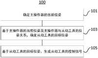
- the present disclosureprovides a control method for master-slave motion, including: determining a current pose of a master operator, where the current pose includes a current position and a current pose; The pose relationship between the manipulator and the driven tool determines the target pose of the driven tool; and based on the target pose of the driven tool, a control signal of the driven tool is generated.
- the present disclosureprovides a robotic system comprising: a master manipulator including a robotic arm, a handle disposed on the robotic arm, and at least one master manipulator sensor disposed at at least one joint on the robotic arm , at least one main operator sensor is used to obtain joint information of at least one joint;
- a driven toolincludes a flexible arm body and an end device; at least one driving device is used to drive the flexible arm body of the driven tool; at least one driving device sensor , coupled with at least one driving device and used to obtain driving information; and a control device, connected in communication with the main operator and the at least one driving device, the control device is configured to determine the current pose of the main operator, the current pose includes The current position and the current posture; the target posture of the driven tool is determined based on the current posture of the main operator and the posture relationship between the main operator and the driven tool; and the driven tool is generated based on the target posture of the driven tool control signal.
- the present disclosureprovides a computer-readable storage medium for storing at least one instruction, and a control method for causing a robot system to perform a master-slave motion when the at least one instruction is executed by a computer, the method comprising: determining a master manipulator The current pose includes the current position and the current pose; based on the current pose of the master manipulator and the pose relationship between the master manipulator and the slave tool, determine the target pose of the slave tool; and based on the slave tool The target pose of , generates the control signal of the driven tool.
- FIG. 1shows a flowchart of a control method for master-slave motion according to some embodiments of the present disclosure
- FIG. 2shows a schematic structural diagram of a robot system according to some embodiments of the present disclosure
- FIG. 3shows a schematic diagram of a coordinate system in a master-slave motion mapping according to some embodiments of the present disclosure
- FIG. 4shows a schematic diagram of a robotic system according to some embodiments of the present disclosure.
- the terms “installed”, “connected”, “connected” and “coupled”should be understood in a broad sense, for example, it may be a fixed connection, or It can be a detachable connection; it can be a mechanical connection or an electrical connection; it can be a direct connection or an indirect connection through an intermediate medium; it can be an internal connection between two components.
- installede.g., it may be a fixed connection, or It can be a detachable connection; it can be a mechanical connection or an electrical connection; it can be a direct connection or an indirect connection through an intermediate medium; it can be an internal connection between two components.
- the end close to the operatoris defined as proximal, proximal or posterior, posterior, and the end close to the surgical patient is defined as distal, distal or anterior, anterior.
- positionrefers to the location of an object or a portion of an object in three-dimensional space (eg, the three translational degrees of freedom can be described using changes in Cartesian X, Y, and Z coordinates, such as along the Cartesian X, respectively axis, three translational degrees of freedom in Y-axis and Z-axis).
- positionrefers to a rotational setting of an object or a portion of an object (eg, three rotational degrees of freedom, which may be described using roll, pitch, and yaw).
- the term "pose”refers to a combination of position and pose of an object or a part of an object, which can be described, for example, using the six parameters of the six degrees of freedom mentioned above.
- the pose of the handle of the main manipulatorcan be represented by a set of joint information of the joints of the main manipulator (eg, a one-dimensional matrix composed of these joint information).
- the pose of the driven toolmay be determined by driving information of the driven tool (eg, driving information of the flexible arm body of the driven tool).
- the joint information of the jointsmay include the rotation angle of the corresponding joint relative to the corresponding joint axis or the distance moved relative to the initial position.
- FIG. 1shows a flowchart 100 of a master-slave motion control method according to some embodiments of the present disclosure
- FIG. 2shows a schematic structural diagram 200 of a robot system according to some embodiments of the present disclosure.
- the method 100may be implemented or performed by hardware, software or firmware.
- method 100may be performed by a robotic system (eg, robotic system 200 shown in FIG. 2 ).
- method 100may be implemented as computer-readable instructions. These instructions may be read and executed by a general purpose processor or a special purpose processor (eg, control device 220 shown in FIG. 2 ).
- a control device for robotic system 200may include a processor configured to perform method 100 .
- these instructionsmay be stored on a computer-readable medium.
- the robotic system 200may include a main console cart 210 , a surgical cart 230 , and a control device 220 .
- the control device 220may be communicatively connected with the main control cart 210 and the operating cart 230 , for example, by cable connection or wireless connection, to implement communication between the main control cart 210 and the operating cart 230 .
- the master trolley 210includes a master manipulator for the operator to operate remotely, and the surgical trolley 230 includes driven tools for performing surgery.
- the master-slave mapping between the master manipulator in the master control trolley and the driven tools in the operating trolleyis realized by the control device 220, and the motion control of the slave tools by the master manipulator is realized.
- the surgical cartincludes at least one driven tool (eg, a surgical tool or a vision tool) disposed on the surgical cart.
- the driven toolis configured to be able to enter the operation area through the sheath, wherein the sheath may be fixed at the patient's surgical port (eg incision or natural opening), and the operation area may be the area where the operation is performed.
- the driven toolmay include an arm body and an end implement.
- the arm body of the driven toolmay be a flexible arm body, and the end instrument may be disposed at the distal end of the flexible arm body.
- the end instruments of the surgical toolmay include, but are not limited to, surgical forceps, electric knives, electric hooks, and the like.
- the end instrument of the vision toolmay include, but is not limited to, an imaging device or an illumination device, and the like.
- the main console cartincludes a main operator, a display, and a foot pedal.
- the main console trolley 210 and the operating trolley 230may take other structures or forms, such as a base, a bracket or a building.
- FIG. 3shows a schematic diagram of a coordinate system in a master-slave motion map according to some embodiments of the present disclosure.
- the definitions of each coordinate system in Figure 3are as follows:
- ⁇ Eb ⁇The camera base coordinate system, the origin is at the base of the vision tool or the exit of the abdominal sheath, Consistent with the axial direction of the extension line of the base or the abdominal sheath, The directions are shown in Figure 3.
- ⁇ Tb ⁇the base coordinate system of the driven tool, the origin is at the base of the driven tool or the exit of the abdominal sheath, Consistent with the axial direction of the extension line of the base or the abdominal sheath, The directions are shown in Figure 3.
- ⁇ Cam ⁇The camera coordinate system, the origin is at the center of the camera, and the direction of the camera axis is direction, the top of the field of view is direction.
- ⁇ Tt ⁇The coordinate system of the end instrument of the driven tool, the origin is at the end of the driven tool, Consistent with the axis direction of the end device, The directions are shown in Figure 3.
- ⁇ ITt ⁇The image coordinate system of the end instrument of the driven tool, which is associated with the image of the end instrument shown on the display.
- ⁇ W ⁇The reference coordinate system, which can be the coordinate system of the space where the main operator is located or the world coordinate system. It can be based on the operator's body sense. When the operator is sitting in front of the main console, the body sense upward is direction, somatosensory forward direction is direction.
- ⁇ Screen ⁇The coordinate system of the display, the origin is at the center of the display, and the inward direction of the vertical screen is Positive direction, the top of the screen is direction.
- ⁇ H ⁇The handle coordinate system of the main operator, the direction of the coordinate axis is shown in Figure 3.
- control method 100 of the master-slave motionwill be described.
- other coordinate systemscan be used to define the control method 100 for realizing the master-slave motion.
- the current pose of the main manipulatormay be determined, and the current pose includes the current position and the current pose.
- the current pose of the master manipulatoris a pose relative to the master manipulator base coordinate system.
- the pose of the master manipulatoris the coordinate system defined by the handle of the master manipulator or a part thereof relative to the master manipulator base coordinate system (for example, the coordinate system defined by the stand or base on which the master manipulator is located, or the world coordinate system ) pose.
- determining the current position of the master manipulatorincludes determining the current position of the handle of the master manipulator relative to the base coordinate system of the master manipulator, and determining the current posture of the master manipulator includes determining the handle of the master manipulator relative to the master manipulator The current pose of the base coordinate system.
- the current pose of the master manipulatormay be determined based on the coordinate transformation.
- the current attitude of the handlemay be determined based on the transformation relationship between the coordinate system of the handle of the main manipulator and the base coordinate system of the master manipulator.
- the base coordinate system of the main manipulatorcan be set on the bracket or base where the main manipulator is located, and during the teleoperation process, the base coordinate system of the main manipulator remains unchanged.
- the current pose of the master manipulatormay be determined based on master manipulator sensors.
- current joint information of at least one joint of the master manipulatoris received, and based on the current joint information of the at least one joint, the current pose of the master manipulator is determined.
- the current pose of the main manipulatoris determined based on the current joint information of at least one joint obtained by the sensor of the main manipulator.
- the main operator sensoris provided at at least one joint position of the main operator.
- the master manipulatorincludes at least one joint, and at least one master manipulator sensor is provided at the at least one joint.
- the joint information (position or angle) of the corresponding jointis obtained based on the main operation sensor, and the current pose of the main manipulator is calculated.
- the current position and current attitude of the main manipulatorare calculated based on a forward kinematics algorithm.
- the master manipulatorincludes at least one gesture joint for controlling the gesture of the handle. Determining the current posture of the handle of the main manipulator includes: obtaining joint information of at least one posture joint, and determining the current posture of the main operator based on the joint information of the at least one posture joint.
- the main manipulatorincludes a robotic arm, and the robotic arm includes a position joint and an attitude joint.
- the attitude jointadjusts the attitude of the main manipulator, and controls the master manipulator to achieve the target attitude through one or more attitude joints.
- the position jointadjusts the position of the main manipulator, and controls the main manipulator to reach the target position through one or more position joints.
- the main manipulator sensoris arranged at the attitude joint and position joint of the robot arm, and is used to obtain joint information (position or angle) corresponding to the attitude joint and the position joint. According to the acquired joint information, the current pose of the handle of the main manipulator relative to the base coordinate system of the main manipulator can be determined.
- the main manipulatorincludes 7 joints, wherein the joint 5, the joint 6 and the joint 7 are posture joints, which are used to adjust the posture of the handle of the main manipulator.
- the joint information(such as angle) acquired by the main manipulator sensor of the posture joint and the forward kinematics algorithm
- Joint 1, joint 2, and joint 3are position joints, which are used to adjust the position of the handle of the main manipulator.
- the current position of the main manipulatoris calculated.
- the target pose of the slave toolmay be determined based on the current pose of the master manipulator and the pose relationship between the master manipulator and the slave tool.
- the master-slave mapping relationship between the master manipulator and the slave toolis established, and the pose of the slave tool is controlled by teleoperating the master manipulator.
- the pose relationshipincludes the relationship between the pose of the slave tool or the image of the slave tool in the display relative to the reference coordinate system and the pose of the master manipulator relative to the reference coordinate system.
- the reference coordinate systemincludes the coordinate system of the space where the main operator is located or the world coordinate system. In some embodiments, the reference coordinate system may be based on the operator's body sense, so the pose of the image of the driven tool on the display relative to the reference coordinate system is considered.
- the pose relationship between the master manipulator and the slave toolmay include a relationship, eg, equal or proportional, between the pose change amount of the master manipulator and the pose change amount of the slave tool.
- Determining the target pose of the slave toolincludes: determining the previous pose of the master manipulator, determining the current pose of the slave tool, and based on the previous pose of the master manipulator, the current pose and the current pose of the slave tool, Determines the target pose of the driven tool.
- the previous pose and the current pose of the main manipulatormay be the poses of the handle of the master manipulator relative to the base coordinate system of the master manipulator.
- the current pose and the target pose of the driven toolmay be the poses of the end device of the driven tool relative to the base coordinate system of the driven tool.
- the driven toolincludes a flexible arm body and an end device disposed at the end of the flexible arm body, and the posture of the driven tool includes the posture of the end device of the driven tool relative to the base coordinate system of the driven tool.
- the base coordinate system of the driven toolmay be the coordinate system of the base on which the driven tool is mounted (eg, the end of the moving arm of the surgical robot), the coordinate system of the sheath through which the driven tool passes (eg, the sheath outlet Coordinate system), the coordinate system of the remote center of Motion (RCM) of the driven tool, etc.
- the base coordinate system of the driven toolcan be set at the location of the sheath outlet, and the base coordinate system of the driven tool remains unchanged during teleoperation.
- the coordinate system transformationcan be performed on the current posture of the end device to obtain the posture relative to other coordinate systems.
- previous joint information of at least one joint of the master manipulatormay be received, and based on the previous joint information of the at least one joint, the previous pose of the master manipulator may be determined.
- the previous pose and the current pose of the handle of the master manipulatorare determined based on the master manipulator sensor reading joint information of the master manipulator at the previous time and the current time.
- the position change amount of the handle of the main manipulatoris determined.
- the attitude change amount of the handle of the main manipulatoris determined.
- current drive information of at least one drive device of the driven toolmay be received, wherein the at least one drive device is used to drive the flexible arm of the driven tool. Based on the current drive information of the at least one drive device, the current pose of the driven tool is determined.
- current driving informationeg, angle
- the current attitude of the driven toolis determined based on the current driving information. For example, the current pose of the driven tool can be calculated through a forward kinematics algorithm.
- the drive device sensormay be provided on the drive device, and the drive device is used to drive the flexible arm of the driven tool.
- the drive unit sensoris used to obtain drive information.
- the current attitude of the driven toolmay be determined based on the drive information.
- the drivemay include at least one drive motor to which the drive sensor is coupled to record and output motor data.
- the motor datamay include binary or hexadecimal numbers that can be converted to obtain the current attitude of the driven tool.
- the drive sensormay comprise a potentiometer or an encoder. Obtain the angle and other information through the potentiometer or encoder, and then determine the current attitude of the driven tool.
- a pose sensormay be employed to obtain the pose of the driven tool.
- the position and attitude sensormay also be an optical fiber sensor, which is disposed through the arm of the driven tool, and is used to sense the position and attitude of the driven tool.
- the pose change amount of the master manipulatormay be determined based on the previous pose and the current pose of the master manipulator.
- the pose change amount of the slave toolcan be determined based on the pose change amount of the master manipulator and the pose relationship between the master manipulator and the slave tool.
- the target pose of the driven toolmay be determined based on the current pose of the driven tool and the amount of change in the driven tool's pose.
- the pose relationshipmay include a position relationship and a pose relationship.
- the positional relationship between the master manipulator and the driven toolmay include the relationship between the position change of the master manipulator and the position change of the slave tool, and the attitude relationship between the master manipulator and the slave tool may include the master operation The relationship between the attitude change of the tool and the attitude change of the driven tool.
- the method 100further includes: determining a current position of the handle of the master manipulator relative to the master manipulator base coordinate system, determining a previous position of the handle relative to the master manipulator base coordinate system, determining the end implement of the driven tool The current position relative to the base coordinate system of the slave tool, and based on the previous position and current position of the handle relative to the base coordinate system of the master manipulator, and the current position of the end implement relative to the base coordinate system of the slave tool, determine the relative position of the end tool relative to the slave tool.
- the target position of the base coordinate system of the mobile toolis determining a current position of the handle of the master manipulator relative to the master manipulator base coordinate system.
- the previous position of the master manipulatoris determined based on the joint information of the master manipulator read by the master manipulator sensor at the previous time
- the master manipulatoris determined based on the joint information of the master manipulator read by the master manipulator sensor at the current time. 's current location.
- the position change amount of the main manipulatoris determined based on the previous position of the handle relative to the base coordinate system of the main manipulator and the current position.
- the current position of the driven toolis determined based on the joint information of the driven tool at the current time read by the driven tool sensor.
- the position change amount of the slave toolis determined based on the position change amount of the master manipulator and the pose relationship between the master manipulator and the slave tool.
- the target position of the driven toolis determined based on the current position of the driven tool and the amount of change in the driven tool's position.
- the pose relationshipincludes a relationship between the pose of the image of the slave tool in the display with respect to the reference coordinate system and the pose of the master manipulator with respect to the reference coordinate system.
- Driven toolsinclude surgical tools and vision tools. During the operation, the surgical tool performs the operation inside the patient, and the vision tool captures the image of the patient's body and transmits the captured image to the operating trolley. After the image is processed by the video processing module in the operating trolley, it is displayed on the monitor of the main control trolley. The operator obtains the pose of the driven tool relative to the reference coordinate system in real time through the image in the display. The pose of the main manipulator relative to the reference coordinate system is the pose that the operator actually perceives.
- the pose change felt by the operator through the remote operation of the master operator and the attitude change of the slave tool perceived by the operator in the displayconform to the preset pose relationship.
- the preset pose relationshipconverts the pose transformation of the master manipulator into the pose change of the slave tool, thereby realizing the pose control of the slave tool.
- the pose relationshipincludes: a position change of the image of the slave tool in the display relative to the reference coordinate system is proportional to the position change of the master manipulator relative to the reference coordinate system.
- the position change of the image of the slave tool in the display relative to the reference coordinate systemis proportional to the position change of the master operator relative to the reference coordinate system, which can be expressed as:
- W ⁇ p ITt on the leftrepresents the position change of the image of the end instrument of the driven tool in the display relative to the reference coordinate system
- W ⁇ p H on the rightrepresents the handle of the master manipulator relative to the reference
- W ⁇ p ITtis proportional to W ⁇ p H with a proportionality factor of k.
- a reference coordinate system relative to the current position of W p ITt (t0) and W p ITt target position in the display image of the driven toolis determined based on the position change amount W ⁇ p ITt driven tool.
- the position change amount W ⁇ p H of the master manipulatorcan be determined based on the previous position W p H ( t0 ) and the current position W p H of the master manipulator with respect to the reference coordinate system. For example, when the teleoperation command is triggered or in the last control cycle, expressed as time t0, the previous position of the handle of the main manipulator relative to the reference coordinate system can be determined based on the joint information of the main manipulator obtained by the sensor of the main manipulator W p H(t0) .
- the current position W p H of the handle of the main manipulator relative to the reference coordinate systemcan be determined based on the joint information of the main manipulator obtained by the sensor of the main manipulator. Based on the previous position W p H ( t0 ) of the main operator at time t0 and the current position W p H of the main operator at time t1 , the position change amount W ⁇ p H of the main operator is obtained.
- the current position W p ITt(t0) of the image of the driven tool in the displaymay be determined based on the driving information of the driven tool.
- the target position W p ITt of the image of the driven tool in the displaycan be determined based on the position change amount W ⁇ p H of the handle and the current position W p ITt(t0) of the image of the driven tool in the display.
- the position change W ⁇ p ITt of the image of the end instrument of the driven tool in the display relative to the reference coordinate systemcan be based on the coordinates of the display relative to the image of the driven tool in the display
- the position change amount Screen ⁇ p ITt of the system and the transformation relationship between the display coordinate system and the world coordinate system W R Screenare determined. Specifically as formula (2),
- the display coordinate system Screen and the camera coordinate system Camhave the same definition of the field of view direction. Therefore, the position change Screen ⁇ p ITt of the image of the driven tool on the display relative to the display coordinate system is consistent with the position change Cam ⁇ p Tt of the driven tool relative to the camera coordinate system. Please refer to formula (3) for details,
- the position change W ⁇ p ITt of the image of the driven tool in the display relative to the reference coordinate systemcan be based on the position change Cam ⁇ p Tt of the end tool of the driven tool relative to the camera coordinate system and the display coordinates
- the transformation relationship between the system and the world coordinate system W R Screenis determined.
- the display coordinate system and the reference coordinate systemhave a predetermined transformation relationship WR Screen .
- the position change Cam ⁇ p Tt of the end tool of the driven tool relative to the camera coordinate systemcan be based on the position of the end tool relative to the camera coordinate system at time t0 Cam p Tt(t0) and the position of the end tool relative to the camera coordinate system at t The difference between the moment relative to the position Cam ⁇ p Tt of the camera coordinate system is determined, as in formula (5),
- Cam ⁇ p TtCam p Tt - Cam p Tt(t0) (5)
- the position change Cam ⁇ p Tt of the end device of the driven tool in the camera coordinate systemcan be based on the change relationship between the camera base coordinate system and the camera coordinate system Cam R Eb , the camera The change relationship Eb R Tb between the base coordinate system and the base coordinate of the driven tool and the position change amount Tb ⁇ p Tt of the end device of the driven tool relative to the base coordinate system of the driven tool are determined. See formula (6) for details,
- Cam ⁇ p TtCam R Eb Eb R Tb Tb ⁇ p Tt (6)
- Tb ⁇ p Ttmay be determined based on the driving information of the driven tool.
- the position change W ⁇ p H of the handle of the main manipulator relative to the reference coordinate systemmay be based on the transformation relationship between the base coordinate system of the master manipulator and the reference coordinate system W R CombX and the handle
- the position change CombX ⁇ p H relative to the base coordinate system of the main operatoris determined, as in formula (7),
- W R CombXis determined by the placement relationship of the main operator.
- the reference coordinate systemhas a predetermined transformation relationship with the master operator base coordinate system.
- the position change amount CombX ⁇ p H of the handle relative to the base coordinate system of the main manipulatorcan be based on the current posture CombX p H of the handle of the main manipulator relative to the base coordinate system of the main manipulator, and The previous pose CombX p H(t0) of the base coordinate system of the manipulator is determined, see formula (8) for details,
- Tb p TtTb p Tt(t0) +k Tb R Cam Screen R CombX ( CombX p H - CombX p H(t0) ) (9)
- the previous position of the handle relative to the master manipulator base coordinate system CombX p H(t0) and the current position CombX p H , the end instrument relative to the slave tool base coordinate systemmay be based on The current position Tb p Tt(t0) , the transformation relationship between the master operator base coordinate system and the display coordinate system Screen R CombX, and the transformation relationship between the camera coordinate system and the slave tool base coordinate system Tb R Cam , determine the relative relationship between the end device and the slave tool.
- the transformation relationship Tb R Cam between the camera coordinate system and the driven tool base coordinate systemmay be based on the transformation relationship Eb R Cam between the camera coordinate system and the camera base coordinate system, and the camera base coordinate system and the driven tool base coordinate system
- the transformation relationship Tb R Ebis determined.
- the transformation relationship between the main operator base coordinate system and the display coordinate system Screen R CombXmay be based on the transformation relationship between the main operator base coordinate system and the reference coordinate system W R CombX , the transformation between the reference coordinate system and the display coordinate system Screen R W determined relationship.
- the attitude change of the image of the driven tool on the display relative to the reference coordinate systemis consistent with the attitude change of the master manipulator relative to the reference coordinate system. In this way, when the operator holds the handle of the main manipulator to operate, based on the principle of intuitive operation, the amount of attitude change of the image of the end instrument of the surgical tool felt by the operator and the attitude change of the handle of the main manipulator felt by the operator The amount is kept the same to improve the precision of the teleoperation.
- the attitude change W R ITt(t0)ITt of the image of the slave tool in the display relative to the reference coordinate systemis consistent with the attitude change W R H(t0)H of the master manipulator relative to the reference coordinate system, which can be expressed as follows:
- the image of the driven tool in the displaycan be determined based on the attitude change amount W R H(t0)H and the current attitude W R ITt(t0) of the driven tool in the display relative to the reference coordinate system at time t0
- the target pose W R ITtbased on the main operation with respect to a reference coordinate system of the previous pose W R H (t0), and to determine the main operator in the current posture of W R t1 time H posture change amount W R H t0 time ( t0)H .
- the image of the driven tool in the displaycan be determined based on the attitude change amount W R H(t0)H and the current attitude W R ITt(t0) of the driven tool in the display relative to the reference coordinate system at time t0
- the target pose W R ITtbased on the main operation with respect to a reference coordinate system of the previous pose W R H (t0), and to determine the main operator in the current posture of W R t1 time H posture change amount W R H t0 time ( t0)H
- the previous posture of the handle of the main manipulator relative to the reference coordinate systemcan be determined based on the joint information of the main manipulator obtained by the sensor of the main manipulator W R H(t0) .
- the current posture W R H of the handle of the main manipulator relative to the reference coordinate systemis determined. Based on the previous posture W R H(t0) of the main operator at time t0 and the current posture W R H of the main operator at time t1, the posture change amount W R H(t0)H of the main operator is obtained.
- driven tooldetermines that the image in the display of the current attitude W R ITt (t0).
- Currentcan pose W R ITt (t0) and a driven tool H image in a display (t0), determines the driven tool W R ITt target gesture in a display image based on the amount of change in posture of the handle W R H.
- the attitude change of the image of the driven tool in the display relative to the reference coordinate system, W R ITt(t0)ITtmay be based on the difference between the reference coordinate system and the display coordinate system
- the transformation relationship W R Screenthe transformation relationship between the display coordinate system and the camera coordinate system Screen R Cam , the previous posture Cam R Tt(t0) of the end device of the driven tool relative to the camera coordinate system, and the end device relative to the camera coordinates
- the current attitude Cam R Tt of the systemis determined. See formula (11) for details,
- W R ITt(t0)ITt( W R Screen Screen R Cam Cam R Tt )( W R Screen Screen R Cam Cam R Tt(t0) ) T (11)
- the attitude change of the master manipulator relative to the reference coordinate system W R H(t0)Hmay be based on the transformation between the reference coordinate system and the master manipulator base coordinate system relationship W R CombX, the main operation of the handle of the current attitude relative to the main operator posture of the base coordinate system previously CombX R H (t0) and the main operation of the handle of the operator with respect to the main base coordinate system CombX R H is determined. See formula (12) for details,
- Tb R TtTb R CombX ( CombX R H ( CombX R H(t0) ) T ) CombX R Tb Tb R Tt(t0) (13)
- equation (13)may be based on the main handle with respect to the base coordinate system operator of a previous pose CombX R H (t0) and current attitude CombX R H, the driven end effector relative to the driven tool
- the current attitude Tb R Tt(t0) of the tool base coordinate system and the transformation relationship between the driven tool base coordinate system and the master manipulator base coordinate system CombX R Tbdetermine the target attitude Tb R of the end device relative to the driven tool base coordinate system Tt .
- the transformation relationship between the slave tool base coordinate system and the master operator base coordinate system CombX R Tbmay be based on the transformation relationship between the slave tool base coordinate system and the camera coordinate system Cam R Tb , the camera coordinate system and the display
- the transformation relationship of the coordinate system Screen R Cam , the transformation relationship between the display coordinate system and the base coordinate system of the main operator, CombX R Screen,are determined.
- the transformation relationship between the driven tool base coordinate system and the camera coordinate system Cam R Tbmay be based on the transformation relationship between the driven tool base coordinate system and the camera base coordinate system Eb R Tb and the camera coordinate system and the camera base coordinate
- the transformation relationship Cam R Eb of the systemis determined.
- the transformation relationship between the display coordinate system and the base coordinate system of the main operator CombX R Screencan be determined based on the transformation relationship between the display coordinate system and the reference coordinate system W R Screen and the transformation relationship between the reference coordinate system and the main operator base coordinate system CombX R W of.
- the cameramay be disposed at the end of the flexible arm body that can be driven, and the transformation relationship between the camera coordinate system and the camera base coordinate system is determined based on the driving information of the flexible arm body.
- the driven tool base coordinate system and the camera base coordinate systemhave a predetermined transformation relationship.
- the visual toolbefore entering the master-slave motion control stage, the visual tool has finished moving, and the current pose of the camera is represented in the camera base coordinate system no longer change.
- the display coordinate systemhas a predetermined transformation relationship with the reference coordinate system. In some embodiments, the reference coordinate system has a predetermined transformation relationship with the master operator base coordinate system. In some embodiments, the display coordinate system has a predetermined transformation relationship with the master operator base coordinate system.
- the attitude change of the slave tool relative to the reference coordinate systemis consistent with the attitude change of the master manipulator relative to the reference coordinate system.
- the change in position of the slave tool relative to the reference frameis proportional to the change in position of the master manipulator relative to the reference frame.
- the position change of the slave tool relative to the reference coordinate systemis proportional to the position change of the master operator relative to the reference coordinate system, which can be expressed as:
- W ⁇ p Tt on the leftrepresents the position change of the slave tool relative to the reference coordinate system
- W ⁇ p H on the rightrepresents the position change of the master operator relative to the reference coordinate system.
- W ⁇ p Tt and W ⁇ p Hare proportional, and the proportionality coefficient is k.
- the position change amount W ⁇ p Tt of the driven toolmay be determined based on the previous position W p Tt ( t0 ) and the current position W p Tt of the driven tool relative to the reference coordinate system.
- the position change amount W ⁇ p H of the main manipulatorcan be determined based on the previous position W p H ( t0 ) and the current position W p H of the main manipulator with respect to the reference coordinate system. For example, when the teleoperation command is triggered or in the last control cycle, expressed as time t0, the previous position of the handle of the main manipulator relative to the reference coordinate system can be determined based on the joint information of the main manipulator obtained by the sensor of the main manipulator W p H(t0) .
- the current position W p H of the handle of the main manipulator relative to the reference coordinate systemis determined based on the joint information of the master manipulator obtained by the master manipulator sensor. Based on the previous position W p H ( t0 ) of the main operator at time t0 and the current position W p H of the main operator at time t1 , the position change amount W ⁇ p H of the main operator is obtained. In addition, at time t0, the current position W p Tt(t0) of the driven tool relative to the reference coordinate system may be determined based on the driving information of the driven tool.
- the position change W ⁇ p Tt of the end tool of the driven tool relative to the reference coordinate systemcan be determined by the position W p Tt of the end tool relative to the reference coordinate system at time t0 and the position of the end tool relative to the reference coordinate system at time t
- the difference of the position W p Tt (t0) of the reference coordinate systemis expressed as formula (15),
- the position change W ⁇ p H of the main operator relative to the world coordinate systemcan be determined by the position W p H (t0) of the main operator relative to the reference coordinate system at time t0 and the position of the main operator relative to the reference coordinate system at time t
- the difference value of the position W p H relative to the reference coordinate systemis expressed as formula (16),
- the left and right sides of the formula (14)are multiplied by the same matrix Tb R W respectively , and the formula (17) is obtained based on the formula (14) to the formula (16),
- Equation (18)is obtained based on the left side of Equation (17),
- Equation (19)is obtained based on the right side of Equation (17),
- Tb p Ttk ⁇ Tb R CombX ( CombX p H - CombX p H(t0) ) + Tb p Tt(t0) (20)
- the previous position of the handle relative to the master manipulator base coordinate system CombX p H(t0) and the current position CombX p H , the end instrument relative to the slave tool base coordinate systemmay be based on The current position Tb p Tt(t0) and the transformation relationship Tb R CombX between the base coordinate system of the master manipulator and the base coordinate system of the driven tool determine the target position Tb p Tt of the end device relative to the base coordinate system of the driven tool.
- the attitude change of the slave tool relative to the reference coordinate systemis consistent with the attitude change of the master manipulator relative to the reference coordinate system. In this way, when the operator holds the handle of the master manipulator and moves to operate the slave tool, based on the principle of intuitive operation, the attitude change of the end instrument of the surgical tool felt by the operator is the same as the master manipulator felt by the operator. The amount of attitude change is consistent to improve the accuracy of teleoperation.
- the attitude change of the slave tool relative to the reference coordinate systemis consistent with the attitude change of the master manipulator relative to the reference coordinate system, which can be expressed as:
- the left side Itrepresents the attitude change amount of the slave tool's attitude relative to the reference coordinate system
- W R H(t0)H on the right siderepresents the attitude change amount of the master manipulator relative to the reference coordinate system.
- the current pose of the driven tool relative to the reference coordinate systemmay be based on and target attitude Determining the attitude change of the driven tool
- the attitude change amount W R H(t0)H of the master manipulatoris determined based on the previous attitude W R H(t0) and the current attitude W R H of the master manipulator relative to the reference coordinate system. For example, when the teleoperation command is triggered or in the last control cycle, expressed as time t0, the previous posture of the handle of the main manipulator relative to the reference coordinate system can be determined based on the joint information of the main manipulator obtained by the sensor of the main manipulator W R H(t0)H .
- the current posture W R H of the handle of the main manipulator relative to the reference coordinate systemis determined.
- the attitude change amount W ⁇ p H of the master manipulatorcan be obtained based on the previous attitude W R H(t0)H of the master manipulator at time t0 and the current attitude W R H of the master manipulator at time t1 .
- the current attitude of the driven tool relative to the reference coordinate systemcan be determined based on the driving information of the driven tool It can be based on the attitude change of the handle W R H(t0)H and the current attitude of the slave tool relative to the reference coordinate system Determines the target pose of the driven tool relative to the reference frame
- the attitude change of the driven tool relative to the reference coordinate systemIt can be based on the current posture of the end device relative to the reference coordinate system at time t0 and the target pose of the end device relative to the reference coordinate system at time t Sure.
- the attitude change amount of the main manipulator relative to the reference coordinate system W R H(t0)Hcan be based on the previous attitude of the handle relative to the reference coordinate system at time t0 W R H(t0) and the handle relative to the reference coordinate system at time t.
- the current attitude W R His determined. See formula (22) for details,
- formula (22)are multiplied by the same matrix Tb R W ( Tb R W ) T respectively , and formula (23) is obtained based on formula (22),
- Equation (24)is obtained based on the left side of Equation (23),
- Equation (25)is obtained based on the right side of Equation (23),
- equation (26)may be based on the main handle with respect to the base coordinate system operator of a previous pose CombX R H (t0) and current attitude CombX R H, the driven end effector relative to the driven tool
- the current attitude Tb R Tt(t0) of the tool base coordinate system and the transformation relationship between the driven tool base coordinate system and the master manipulator base coordinate system CombX R Tbdetermine the target attitude Tb R of the end device relative to the driven tool base coordinate system Tt .
- a control signal of the driven toolmay be generated based on the target pose of the driven tool.
- a drive signal for driving at least one drive device of the driven toolis generated based on the target pose of the driven tool.
- a drive signal for driving at least one drive of the driven toolis generated based on the current pose and the target pose of the driven tool. For example, a drive signal for driving at least one drive of the driven tool is calculated based on an inverse kinematics algorithm.
- control method of the master-slave motionfurther includes: performing the control of the master-slave motion in a predetermined period. For example, in the master-slave motion control process, the current pose of the master manipulator is read in a predetermined period, the target pose of the slave tool is determined according to the current pose of the master manipulator and the pose relationship between the master and the slave, and the control The driven tool moves to the target pose to realize the motion control of the driven tool by the master manipulator.
- the previous pose of the master manipulatorincludes the pose when the master manipulator and the slave tool first establish the master-slave mapping relationship or in the last cycle.
- the current pose of the master manipulatorincludes the pose of the master manipulator at the current cycle (eg, the pose after teleoperation).
- the current pose of the slave toolincludes the pose of the current cycle (for example, the pose before the master-slave control is not performed in the current cycle), and the target pose includes the target pose of the master-slave control in the current cycle.
- the current pose of the master manipulatormatches the target pose of the slave tool.
- Surgical robotshave high requirements for operation accuracy and human-computer interaction experience.
- Surgical robotsusually perform surgical operations through a vision system.
- the pose of the camera in the vision systemis usually adjustable in order to adjust the angle and extent of the field of view.
- the adjustment of the camera posemay lead to changes in the observation experience of the operator (eg, the surgeon).
- Some embodiments of the present disclosuretake into account the positions and postures of the camera and the display, optimize the operator's use experience, can accurately and quickly control the movement of the driven tool to the desired position, and can break through the movement limit of the master operator to achieve better Large operating range.
- some embodiments of the present disclosuremay alleviate or even avoid the visual and actual differences brought by the direct mapping of the pose of the master manipulator to the pose of the slave tool, as well as the pose limitation of the master manipulator controlling the slave tool.
- the limit of the range of motion of the driven toolmay alleviate or even avoid the visual and actual differences brought by the direct mapping of the pose of the master manipulator to the pose of the slave tool, as well as the pose limitation of the master manipulator controlling the slave tool.
- FIG. 4shows a schematic diagram 400 of a robotic system according to some embodiments of the present disclosure.
- the robot system 400includes: a master manipulator 410 , a driven tool 420 , a driving device 430 and a control device 440 .
- the main manipulator 410includes a manipulator, a handle provided on the manipulator, and at least one master manipulator sensor provided at at least one joint of the manipulator, and the at least one master manipulator sensor is used to obtain joint information of the at least one joint.
- the driven tool 420includes a flexible arm and a tip instrument.
- the drive device 430is used to drive the flexible arm of the driven tool, and at least one drive device sensor is coupled to the at least one drive device and used to obtain drive information.
- the control device 440is connected in communication with the main operator 410 and the at least one drive device 430 .
- the control device 440is configured to perform the control method of the master-slave motion according to some embodiments of the present disclosure.
- the main manipulator 410includes a six-degree-of-freedom manipulator arm, and each joint on the six-degree-of-freedom manipulator is provided with a main manipulator sensor, and joint information (eg, joints) is generated by the main manipulator sensor of each joint. angle data).
- the master operator sensoremploys potentiometers and/or encoders.
- the driven tool 420includes a multi-joint six degrees of freedom flexible arm.
- the driving device 430is used to drive the flexible arm body of the driven tool 420, and obtains driving information corresponding to the driven tool through the driving device sensor.
- control device 440is in communication with the main operator 410 and the drive device 430 .
- the main operator 410, the driving device 430 and the control device 440may be connected through a data transmission bus, including but not limited to wireless data transmission, wired data connection, or a combination of various data communication methods.
- the data transmission buscan use a communication protocol bus, such as a controller area network bus (CAN, Controller Area Network).
- CANController Area Network
- the control device 440is configured to perform the control method of the master-slave motion in some embodiments of the present disclosure.
- the control unitis used to receive network data packets (eg joint information) sent by the main operator sensor and the drive unit sensor.
- the control devicecalculates, according to the joint information of the driven tool and the joint information of the master manipulator, the joint target value of the handle of the master manipulator reaching the target attitude consistent with the current attitude of the slave tool, and converts it into a drive signal and sends it to the drive device 430 .
- the driving device 430receives the driving signal through the network data packet, sends it to each Epos control tool through the CAN bus, and drives each motor of the main operator to move the main operator to move in place, so that the handle of the main operator and the attitude of the driven tool are matched. .
- the main manipulatormay be provided with a controller, and the controller may calculate the attitude data of the master manipulator according to the joint information obtained by each main manipulator sensor, and send the calculated attitude data to the control device.
- the control devicemay also calculate and obtain the attitude data of the main manipulator according to the joint data sent by the sensor of the main manipulator.
- a control method for master-slave motioncomprising:
- the current poseincludes the current position and the current pose
- a control signal for the driven toolis generated based on the target pose of the driven tool.
- the amount of change in the position of the slave tool or the image of the slave tool in the display relative to the reference coordinate systemis proportional to the amount of change in the position of the master manipulator relative to the reference coordinate system;
- the attitude change amount of the driven tool or the image of the driven tool in the display relative to the reference coordinate systemis consistent with the attitude change amount of the master manipulator relative to the reference coordinate system.
- a target pose of the slave toolis determined based on the previous pose and the current pose of the master manipulator and the current pose of the slave tool.
- determining the target position of the end device relative to the base coordinate system of the driven toolcomprises:
- the transformation relationship between the base coordinate system of the master manipulator and the coordinate system of the display, and the difference between the base coordinate system of the camera and the slave tool base coordinate systemdetermines a target position of the end tool relative to the driven tool base coordinate system.
- determining the target position of the end device relative to the base coordinate system of the driven toolcomprises:
- the transformation relationship between the master manipulator base coordinate system and the slave tool base coordinate system, and the relative The current position of the base coordinate system of the driven toolis determined, and the target position of the end device relative to the base coordinate system of the driven tool is determined.
- the current posture of the actuator relative to the base coordinate system of the driven tooldetermines the target posture of the end device relative to the base coordinate system of the driven tool.
- the current pose of the main manipulatoris determined.
- a drive signal for driving at least one drive device of the driven toolis generated.
- a current pose of the driven toolis determined, where the current pose includes a current position and a current pose.
- control methodaccording to any one of items 1 to 20, further comprising: performing control of the master-slave motion in a predetermined cycle.
- a robotic systemcomprising:
- a master manipulatorincludes a robotic arm, a handle provided on the robotic arm, and at least one master manipulator sensor provided at at least one joint on the robotic arm, the at least one master manipulator sensor being used to obtain the Describe the joint information of at least one joint;
- At least one driving device for driving the flexible arm of the driven toolfor driving the flexible arm of the driven tool
- At least one drive sensorcoupled to the at least one drive and for obtaining drive information
- control deviceconnected in communication with the master operator and the at least one drive device, the control device being configured to perform the master-slave motion control method according to any one of claims 1-21.
- a computer devicecomprising:
- a processorcoupled to the memory and configured to execute the at least one instruction to perform the master-slave motion control method according to any one of claims 1-21.
- a computer-readable storage mediumfor storing at least one instruction that, when executed by a computer, causes a robot system to implement the master-slave motion control method according to any one of claims 1-21.
Landscapes
- Health & Medical Sciences (AREA)
- Engineering & Computer Science (AREA)
- Life Sciences & Earth Sciences (AREA)
- Surgery (AREA)
- Robotics (AREA)
- Medical Informatics (AREA)
- Biomedical Technology (AREA)
- Heart & Thoracic Surgery (AREA)
- Nuclear Medicine, Radiotherapy & Molecular Imaging (AREA)
- Molecular Biology (AREA)
- Animal Behavior & Ethology (AREA)
- General Health & Medical Sciences (AREA)
- Public Health (AREA)
- Veterinary Medicine (AREA)
- Mechanical Engineering (AREA)
- Manipulator (AREA)
Abstract
Description
Translated fromChinese相关申请的交叉引用CROSS-REFERENCE TO RELATED APPLICATIONS
本申请要求于2020年7月1日提交的、申请号为2020106274778、发明名称为“一种遥操作主从映射运动控制系统及方法”的中国专利申请的优先权,该申请的全文以引用方式整体结合于此。This application claims the priority of the Chinese patent application filed on July 1, 2020 with the application number of 2020106274778 and the invention titled "A teleoperated master-slave mapping motion control system and method", the full text of which is by reference The whole is combined here.
本公开涉及机器人领域,尤其涉及一种主从运动的控制方法、机器人系统、设备及存储介质。The present disclosure relates to the field of robots, and in particular, to a master-slave motion control method, a robot system, a device, and a storage medium.
随着科技的发展,通过医疗机器人辅助医疗工作人员进行手术得到了快速的发展,医疗机器人不仅可以帮助医疗工作人员进行一系列的医疗诊断和辅助治疗,还能有效缓解医疗资源的紧张问题。With the development of science and technology, the use of medical robots to assist medical staff in surgery has developed rapidly. Medical robots can not only help medical staff to carry out a series of medical diagnosis and auxiliary treatment, but also effectively relieve the shortage of medical resources.
通常,医疗机器人包括用于执行操作的从动工具及用于控制从动工具运动的主操作器。在实际场景中,从动工具被设置成能够进入操作区域,医疗工作人员通过遥操作主操作器进而控制从动工具在操作区域中的运动,实现医疗操作。一般医疗机器人通过主操作器与从动工具之间的运动转换实现主操作器对从动工具的运动控制。Typically, a medical robot includes a driven tool for performing operations and a master manipulator for controlling the motion of the driven tool. In an actual scenario, the driven tool is set to be able to enter the operation area, and the medical staff controls the movement of the driven tool in the operation area by teleoperating the master manipulator to realize the medical operation. The general medical robot realizes the motion control of the master manipulator to the slave tool through the motion conversion between the master manipulator and the slave tool.
手术机器人对操作精度和人机交互体验要求很高。例如,手术机器人可以通过相机采集从动工具的图像,并通过显示器进行显示。操作者(例如手术医生)通过显示器中的图像获取从动工具的位置和姿态,并通过遥操作主操作器控制从动工具的位置和姿态。这样,相机和显示器的位置和姿态会影响操作者下一步的操作方向和距离。 因此,需要提高手术机器人的主从运动控制的精度,以实现主操作器与从动工具之间主从运动控制的目标结果与操作者的感官意愿的一致性。Surgical robots have high requirements for operation accuracy and human-computer interaction experience. For example, a surgical robot can capture an image of a driven tool with a camera and display it on a monitor. An operator (eg, a surgeon) acquires the position and attitude of the driven tool through the images in the display, and controls the position and attitude of the driven tool through the teleoperated master manipulator. In this way, the position and posture of the camera and the display will affect the operator's next operation direction and distance. Therefore, it is necessary to improve the precision of the master-slave motion control of the surgical robot, so as to achieve the consistency between the target result of the master-slave motion control between the master manipulator and the slave tool and the operator's sensory wishes.
发明内容SUMMARY OF THE INVENTION
在一些实施例中,本公开提供了一种主从运动的控制方法,包括:确定主操作器的当前位姿,当前位姿包括当前位置和当前姿态;基于主操作器的当前位姿及主操作器与从动工具的位姿关系,确定从动工具的目标位姿;以及基于从动工具的目标位姿,生成从动工具的控制信号。In some embodiments, the present disclosure provides a control method for master-slave motion, including: determining a current pose of a master operator, where the current pose includes a current position and a current pose; The pose relationship between the manipulator and the driven tool determines the target pose of the driven tool; and based on the target pose of the driven tool, a control signal of the driven tool is generated.
在一些实施例中,本公开提供了一种机器人系统,包括:主操作器,包括机械臂、设置在机械臂上的手柄以及设置在机械臂上的至少一个关节处的至少一个主操作器传感器,至少一个主操作器传感器用于获得至少一个关节的关节信息;从动工具,包括柔性臂体和末端器械;至少一个驱动装置,用于驱动从动工具的柔性臂体;至少一个驱动装置传感器,与至少一个驱动装置耦合并且用于获得驱动信息;以及控制装置,与主操作器和至少一个驱动装置通信连接,控制装置被配置成用于确定主操作器的当前位姿,当前位姿包括当前位置和当前姿态;基于主操作器的当前位姿及主操作器与从动工具的位姿关系,确定从动工具的目标位姿;以及基于从动工具的目标位姿,生成从动工具的控制信号。In some embodiments, the present disclosure provides a robotic system comprising: a master manipulator including a robotic arm, a handle disposed on the robotic arm, and at least one master manipulator sensor disposed at at least one joint on the robotic arm , at least one main operator sensor is used to obtain joint information of at least one joint; a driven tool includes a flexible arm body and an end device; at least one driving device is used to drive the flexible arm body of the driven tool; at least one driving device sensor , coupled with at least one driving device and used to obtain driving information; and a control device, connected in communication with the main operator and the at least one driving device, the control device is configured to determine the current pose of the main operator, the current pose includes The current position and the current posture; the target posture of the driven tool is determined based on the current posture of the main operator and the posture relationship between the main operator and the driven tool; and the driven tool is generated based on the target posture of the driven tool control signal.
在一些实施例中,本公开提供了一种计算机可读存储介质,用于存储至少一条指令,至少一条指令由计算机执行时致使机器人系统执行主从运动的控制方法,方法包括:确定主操作器的当前位姿,当前位姿包括当前位置和当前姿态;基于主操作器的当前位姿及主操作器与从动工具的位姿关系,确定从动工具的目标位姿;以及基于从动工具的目标位姿,生成从动工具的控制信号。In some embodiments, the present disclosure provides a computer-readable storage medium for storing at least one instruction, and a control method for causing a robot system to perform a master-slave motion when the at least one instruction is executed by a computer, the method comprising: determining a master manipulator The current pose includes the current position and the current pose; based on the current pose of the master manipulator and the pose relationship between the master manipulator and the slave tool, determine the target pose of the slave tool; and based on the slave tool The target pose of , generates the control signal of the driven tool.
为了更清楚地说明本公开实施例中的技术方案,下面将对本公开实施例描述中所需要使用的附图作简单的介绍。下面描述中的附图仅仅示出本公开的一些实施例,对于本领域普通技术人员来讲,在不付出创造性劳动的前提下,还可以根据本公开实施例的内容和这些附图获得其他的实施例。In order to illustrate the technical solutions in the embodiments of the present disclosure more clearly, the following briefly introduces the accompanying drawings that need to be used in the description of the embodiments of the present disclosure. The accompanying drawings in the following description only show some embodiments of the present disclosure. For those of ordinary skill in the art, without any creative effort, others can also be obtained according to the contents of the embodiments of the present disclosure and these drawings. Example.
图1示出根据本公开一些实施例的主从运动的控制方法流程图;FIG. 1 shows a flowchart of a control method for master-slave motion according to some embodiments of the present disclosure;
图2示出根据本公开一些实施例的机器人系统的结构示意图;FIG. 2 shows a schematic structural diagram of a robot system according to some embodiments of the present disclosure;
图3示出根据本公开一些实施例的主从运动映射中的坐标系示意图;3 shows a schematic diagram of a coordinate system in a master-slave motion mapping according to some embodiments of the present disclosure;
图4示出根据本公开一些实施例的机器人系统的示意图。4 shows a schematic diagram of a robotic system according to some embodiments of the present disclosure.
为使本公开解决的技术问题、采用的技术方案和达到的技术效果更加清楚,下面将结合附图对本公开实施例的技术方案作进一步的详细描述,显然,所描述的实施例仅仅是本公开示例性实施例,而不是全部的实施例。In order to make the technical problems solved by the present disclosure, the technical solutions adopted and the technical effects achieved more clearly, the technical solutions of the embodiments of the present disclosure will be described in further detail below with reference to the accompanying drawings. Obviously, the described embodiments are only the present disclosure. Exemplary embodiments, but not all embodiments.
在本公开的描述中,需要说明的是,术语“中心”、“上”、“下”、“左”、“右”、“竖直”、“水平”、“内”、“外”等指示的方位或位置关系为基于附图所示的方位或位置关系,仅是为了便于描述本公开和简化描述,而不是指示或暗示所指的装置或元件必须具有特定的方位、以特定的方位构造和操作,因此不能理解为对本公开的限制。此外,术语“第一”、“第二”仅用于描述目的,而不能理解为指示或暗示相对重要性。在本公开的描述中,需要说明的是,除非另有明确的规定和限定,术语“安装”、“相连”、“连接”、“耦合”应做广义理解,例如,可以是固定连接,也可以是可拆卸连接;可以是机械连接,也可以是电连接;可以是直接相连,也可以通过中间媒介间接相连;可以是两个元件内部的连通。对于本领域的普通技术人 员而言,可以根据具体情况理解上述术语在本公开中的具体含义。在本公开中,定义靠近操作者(例如医生)的一端为近端、近部或后端、后部,靠近手术患者的一端为远端、远部或前端、前部。本领域技术人员可以理解,本公开的实施例可以用于医疗器械或手术机器人,也可以用于其他非医疗装置。In the description of the present disclosure, it should be noted that the terms "center", "upper", "lower", "left", "right", "vertical", "horizontal", "inner", "outer", etc. The indicated orientation or positional relationship is based on the orientation or positional relationship shown in the drawings, and is only for the convenience of describing the present disclosure and simplifying the description, rather than indicating or implying that the indicated device or element must have a specific orientation or a specific orientation. construction and operation, and therefore should not be construed as limiting the present disclosure. Furthermore, the terms "first" and "second" are used for descriptive purposes only and should not be construed to indicate or imply relative importance. In the description of the present disclosure, it should be noted that, unless otherwise expressly specified and limited, the terms "installed", "connected", "connected" and "coupled" should be understood in a broad sense, for example, it may be a fixed connection, or It can be a detachable connection; it can be a mechanical connection or an electrical connection; it can be a direct connection or an indirect connection through an intermediate medium; it can be an internal connection between two components. For those of ordinary skill in the art, the specific meanings of the above terms in the present disclosure can be understood according to specific situations. In the present disclosure, the end close to the operator (eg doctor) is defined as proximal, proximal or posterior, posterior, and the end close to the surgical patient is defined as distal, distal or anterior, anterior. Those skilled in the art can understand that the embodiments of the present disclosure can be used in medical instruments or surgical robots, and can also be used in other non-medical devices.
在本公开中,术语“位置”指对象或对象的一部分在三维空间中的定位(例如,可使用笛卡尔X、Y和Z坐标方面的变化描述三个平移自由度,例如分别沿笛卡尔X轴、Y轴和Z轴的三个平移自由度)。在本公开中,术语“姿态”指对象或对象的一部分的旋转设置(例如,三个旋转自由度,可使用滚转、俯仰和偏转来描述这三个旋转自由度)。在本公开中,术语“位姿”指对象或对象的一部分的位置和姿态的组合,例如可使用以上提到的六个自由度中的六个参数来描述。在本公开中,主操作器的手柄的位姿可由主操作器关节的关节信息的集合(例如由这些关节信息组成的一维矩阵)来表示。从动工具的位姿可由从动工具的驱动信息(例如,从动工具的柔性臂体的驱动信息)来确定。在本公开中,关节的关节信息可以包括相应关节相对于相应的关节轴所旋转的角度或者相对于初始位置移动的距离。In this disclosure, the term "position" refers to the location of an object or a portion of an object in three-dimensional space (eg, the three translational degrees of freedom can be described using changes in Cartesian X, Y, and Z coordinates, such as along the Cartesian X, respectively axis, three translational degrees of freedom in Y-axis and Z-axis). In this disclosure, the term "pose" refers to a rotational setting of an object or a portion of an object (eg, three rotational degrees of freedom, which may be described using roll, pitch, and yaw). In the present disclosure, the term "pose" refers to a combination of position and pose of an object or a part of an object, which can be described, for example, using the six parameters of the six degrees of freedom mentioned above. In the present disclosure, the pose of the handle of the main manipulator can be represented by a set of joint information of the joints of the main manipulator (eg, a one-dimensional matrix composed of these joint information). The pose of the driven tool may be determined by driving information of the driven tool (eg, driving information of the flexible arm body of the driven tool). In the present disclosure, the joint information of the joints may include the rotation angle of the corresponding joint relative to the corresponding joint axis or the distance moved relative to the initial position.
图1示出根据本公开一些实施例的主从运动的控制方法流程图100,图2示出根据本公开一些实施例的机器人系统的结构示意图200。方法100可以由硬件、软件或者固件实现或执行。在一些实施例中,方法100可以由机器人系统(例如,图2所示的机器人系统200)执行。在一些实施例中,方法100可以实现为计算机可读的指令。这些指令可以由通用处理器或专用处理器(例如,图2所示的控制装置220)读取并执行。例如,用于机器人系统200的控制装置可以包括处理器,被配置为执行方法100。在一些实施例中,这些指令可以存储在计算机可读介质上。FIG. 1 shows a
在一些实施例中,如图2所示,机器人系统200可以包括主控台车210、手术台车230及控制装置220。控制装置220可以与主控台车210和手术台车230通信连接, 例如可通过线缆连接、也可以通过无线连接,以实现主控台车210和手术台车230之间的通信。主控台车210包括供操作者遥操作的主操作器,手术台车230包括用于执行手术的从动工具。通过控制装置220实现主控台车中的主操作器与手术台车中的从动工具之间的主从映射,实现主操作器对从动工具的运动控制。在一些实施例中,手术台车包括设置在手术台车上的至少一个从动工具(如手术工具或视觉工具)。并且从动工具被设置成能够通过鞘套进入操作区域,其中,鞘套可以固定在患者的手术口(例如切口或自然开口)处,操作区域可以是进行手术的区域。从动工具可以包括臂体和末端器械。从动工具的臂体可以是柔性臂体,末端器械可以设置在柔性臂体远端。手术工具的末端器械可以包括但不限于手术钳、电刀、电勾等。视觉工具的末端器械可以包括但不限于成像装置或照明装置等。在一些实施例中,主控台车包括主操作器、显示器及脚踏板。本领域技术人员可以理解,主控台车210和手术台车230可以采用其他结构或者形式,例如基座、支架或建筑物等。In some embodiments, as shown in FIG. 2 , the
图3示出根据本公开一些实施例的主从运动映射中的坐标系示意图。在图3中各坐标系的定义如下:FIG. 3 shows a schematic diagram of a coordinate system in a master-slave motion map according to some embodiments of the present disclosure. The definitions of each coordinate system in Figure 3 are as follows:
{Eb}:相机基坐标系,原点位于视觉工具的基座或者入腹鞘套出口,

{Tb}:从动工具基坐标系,原点位于从动工具的基座或者入腹鞘套出口,

{Cam}:相机坐标系,原点位于相机中心,相机轴线方向为

{Tt}:从动工具的末端器械的坐标系,原点位于从动工具的末端,

{ITt}:从动工具的末端器械的图像坐标系,与显示器中所显示的末端器械的图像 相关联。{ITt}: The image coordinate system of the end instrument of the driven tool, which is associated with the image of the end instrument shown on the display.
{W}:参考坐标系,可以是主操作器所在空间的坐标系或者世界坐标系,可以以操作者的体感为基准,当操作者端坐于主控台之前时,体感向上为

{Screen}:显示器坐标系,原点位于显示器中心,垂直屏幕画面向内方向为

{CombX}:主操作器基坐标系,坐标轴方向如图3所示。{CombX}: The base coordinate system of the main operator, the direction of the coordinate axis is shown in Figure 3.
{H}:主操作器的手柄坐标系,坐标轴方向如图3所示。{H}: The handle coordinate system of the main operator, the direction of the coordinate axis is shown in Figure 3.
下文中,以图3所示的坐标系为例,对主从运动的控制方法100进行描述。但是,本领域技术人员可以理解,可以采用其他坐标系定义实现主从运动的控制方法100。Hereinafter, taking the coordinate system shown in FIG. 3 as an example, the
如图1所示,在步骤101,可以确定主操作器的当前位姿,当前位姿包括当前位置和当前姿态。在一些实施例中,主操作器的当前位姿是相对于主操作器基坐标系的位姿。例如,主操作器的位姿是主操作器的手柄或其一部分定义的坐标系相对于主操作器基坐标系(例如,主操作器所在的支架或基座定义的坐标系、或世界坐标系)的位姿。在一些实施例中,确定主操作器的当前位置包括确定主操作器的手柄相对于主操作器基坐标系的当前位置,确定主操作器的当前姿态包括确定主操作器的手柄相对于主操作器基坐标系的当前姿态。As shown in FIG. 1, in
在一些实施例中,可以基于坐标变换确定主操作器的当前位姿。例如,可以基于主操作器的手柄的坐标系与主操作器基坐标系之间的变换关系确定手柄的当前姿态。通常情况下,主操作器基坐标系可以设置在主操作器所在的支架或基座上,且在遥操作过程中,主操作器基坐标系保持不变。In some embodiments, the current pose of the master manipulator may be determined based on the coordinate transformation. For example, the current attitude of the handle may be determined based on the transformation relationship between the coordinate system of the handle of the main manipulator and the base coordinate system of the master manipulator. Usually, the base coordinate system of the main manipulator can be set on the bracket or base where the main manipulator is located, and during the teleoperation process, the base coordinate system of the main manipulator remains unchanged.
在一些实施例中,可以基于主操作器传感器确定主操作器的当前位姿。在一些实 施例中,接收主操作器的至少一个关节的当前关节信息,并且基于至少一个关节的当前关节信息,确定主操作器的当前位姿。例如,主操作器的当前位姿是基于主操作器传感器获得的至少一个关节的当前关节信息确定的。主操作器传感器设置在主操作器的至少一个关节位置处。例如,主操作器包括至少一个的关节,在至少一个关节处设置至少一个主操作器传感器。基于主操作传感器获取对应关节的关节信息(位置或者角度),计算主操作器的当前位姿。例如,基于正向运动学算法计算主操作器的当前位置和当前姿态。In some embodiments, the current pose of the master manipulator may be determined based on master manipulator sensors. In some embodiments, current joint information of at least one joint of the master manipulator is received, and based on the current joint information of the at least one joint, the current pose of the master manipulator is determined. For example, the current pose of the main manipulator is determined based on the current joint information of at least one joint obtained by the sensor of the main manipulator. The main operator sensor is provided at at least one joint position of the main operator. For example, the master manipulator includes at least one joint, and at least one master manipulator sensor is provided at the at least one joint. The joint information (position or angle) of the corresponding joint is obtained based on the main operation sensor, and the current pose of the main manipulator is calculated. For example, the current position and current attitude of the main manipulator are calculated based on a forward kinematics algorithm.
在一些实施例中,主操作器包括用于控制手柄的姿态的至少一个姿态关节。确定主操作器的手柄的当前姿态包括:获得至少一个姿态关节的关节信息,并且基于至少一个姿态关节的关节信息,确定主操作器的当前姿态。主操作器包括机械臂,机械臂包括位置关节以及姿态关节。姿态关节调整主操作器的姿态,通过一个或者多个姿态关节控制主操作器达到目标姿态。位置关节调整主操作器的位置,通过一个或者多个的位置关节控制主操作器达到目标位置。主操作器传感器设置在度机械臂的姿态关节以及位置关节处,用于获取姿态关节以及位置关节对应的关节信息(位置或者角度)。根据获取到的关节信息,可以确定主操作器的手柄相对于主操作器的基坐标系的当前位姿。例如,主操作器包括7个关节,其中,关节5、关节6和关节7为姿态关节,用于调整主操作器的手柄的姿态。基于姿态关节的主操作器传感器获取的关节信息(如角度)以及正向运动学算法,计算主操作器的当前姿态。关节1、关节2、关节3为位置关节,用于调整主操作器的手柄的位置。基于位置关节的主操作器传感器获取的关节信息(如位置)以及正向运动学算法,计算主操作器的当前位置。In some embodiments, the master manipulator includes at least one gesture joint for controlling the gesture of the handle. Determining the current posture of the handle of the main manipulator includes: obtaining joint information of at least one posture joint, and determining the current posture of the main operator based on the joint information of the at least one posture joint. The main manipulator includes a robotic arm, and the robotic arm includes a position joint and an attitude joint. The attitude joint adjusts the attitude of the main manipulator, and controls the master manipulator to achieve the target attitude through one or more attitude joints. The position joint adjusts the position of the main manipulator, and controls the main manipulator to reach the target position through one or more position joints. The main manipulator sensor is arranged at the attitude joint and position joint of the robot arm, and is used to obtain joint information (position or angle) corresponding to the attitude joint and the position joint. According to the acquired joint information, the current pose of the handle of the main manipulator relative to the base coordinate system of the main manipulator can be determined. For example, the main manipulator includes 7 joints, wherein the joint 5, the joint 6 and the joint 7 are posture joints, which are used to adjust the posture of the handle of the main manipulator. Based on the joint information (such as angle) acquired by the main manipulator sensor of the posture joint and the forward kinematics algorithm, the current posture of the main manipulator is calculated. Joint 1, joint 2, and joint 3 are position joints, which are used to adjust the position of the handle of the main manipulator. Based on the joint information (eg position) acquired by the main manipulator sensor of the position joint and the forward kinematics algorithm, the current position of the main manipulator is calculated.
在步骤103,可以基于主操作器的当前位姿及主操作器与从动工具的位姿关系,确定从动工具的目标位姿。例如,建立主操作器与从动工具的主从映射关系,通过遥操作主操作器以控制从动工具的位姿。位姿关系包括从动工具或者从动工具在显示器 中的图像相对于参考坐标系的位姿与主操作器相对于参考坐标系的位姿之间的关系。参考坐标系包括主操作器所在空间的坐标系或者世界坐标系。在一些实施例中,参考坐标系可以以操作者的体感为基准,因此考虑从动工具在显示器中的图像相对于参考坐标系的位姿。In
在一些实施例中,主操作器与从动工具之间的位姿关系可以包括主操作器的位姿变化量与从动工具的位姿变化量之间的关系,例如相等或者成比例。确定从动工具的目标位姿包括:确定主操作器的先前位姿,确定从动工具的当前位姿,并且基于主操作器的先前位姿、当前位姿以及从动工具的当前位姿,确定从动工具的目标位姿。主操作器的先前位姿以及当前位姿可以是主操作器的手柄相对于主操作器基坐标系的位姿。从动工具的当前位姿以及目标位姿可以是从动工具的末端器械相对于从动工具基坐标系的位姿。In some embodiments, the pose relationship between the master manipulator and the slave tool may include a relationship, eg, equal or proportional, between the pose change amount of the master manipulator and the pose change amount of the slave tool. Determining the target pose of the slave tool includes: determining the previous pose of the master manipulator, determining the current pose of the slave tool, and based on the previous pose of the master manipulator, the current pose and the current pose of the slave tool, Determines the target pose of the driven tool. The previous pose and the current pose of the main manipulator may be the poses of the handle of the master manipulator relative to the base coordinate system of the master manipulator. The current pose and the target pose of the driven tool may be the poses of the end device of the driven tool relative to the base coordinate system of the driven tool.
从动工具包括柔性臂体和设置在柔性臂体末端的末端器械,从动工具的位姿包括从动工具的末端器械相对于从动工具的基坐标系的姿态。从动工具的基坐标系可以是从动工具所安装的基座(例如,手术机器人的运动臂末端)的坐标系、从动工具所穿过的鞘管的坐标系(例如,鞘管出口的坐标系)、从动工具的远端运动中心点(Remote Center of Motion,RCM)的坐标系等。例如,从动工具的基坐标系可以设置在鞘管出口位置处,且在遥操作过程中,从动工具的基坐标系保持不变。可以对末端器械的当前姿态进行坐标系变换,得到相对于其他坐标系的姿态。The driven tool includes a flexible arm body and an end device disposed at the end of the flexible arm body, and the posture of the driven tool includes the posture of the end device of the driven tool relative to the base coordinate system of the driven tool. The base coordinate system of the driven tool may be the coordinate system of the base on which the driven tool is mounted (eg, the end of the moving arm of the surgical robot), the coordinate system of the sheath through which the driven tool passes (eg, the sheath outlet Coordinate system), the coordinate system of the remote center of Motion (RCM) of the driven tool, etc. For example, the base coordinate system of the driven tool can be set at the location of the sheath outlet, and the base coordinate system of the driven tool remains unchanged during teleoperation. The coordinate system transformation can be performed on the current posture of the end device to obtain the posture relative to other coordinate systems.
在一些实施例中,可以接收主操作器的至少一个关节的先前关节信息,并且基于至少一个关节的先前关节信息,确定主操作器的先前位姿。例如,基于主操作器传感器读取主操作器在先前时间以及当前时间的关节信息,确定主操作器的手柄的先前位姿和当前位姿。基于手柄相对于主操作器基坐标系的先前位置以及当前位置,确定主操作器的手柄的位置变化量。基于手柄相对于主操作器基坐标系的先前姿态以及当前 姿态,确定主操作器的手柄的姿态变化量。In some embodiments, previous joint information of at least one joint of the master manipulator may be received, and based on the previous joint information of the at least one joint, the previous pose of the master manipulator may be determined. For example, the previous pose and the current pose of the handle of the master manipulator are determined based on the master manipulator sensor reading joint information of the master manipulator at the previous time and the current time. Based on the previous position and the current position of the handle relative to the base coordinate system of the main manipulator, the position change amount of the handle of the main manipulator is determined. Based on the previous attitude and the current attitude of the handle relative to the base coordinate system of the main manipulator, the attitude change amount of the handle of the main manipulator is determined.
在一些实施例中,可以接收从动工具的至少一个驱动装置的当前驱动信息,其中至少一个驱动装置用于驱动从动工具的柔性臂体。基于至少一个驱动装置的当前驱动信息,确定从动工具的当前位姿。在一些实施例中,通过驱动装置传感器获得从动工具的当前驱动信息(如角度),基于当前驱动信息确定从动工具的当前姿态。例如,可以通过正向运动学算法,计算从动工具的当前姿态。In some embodiments, current drive information of at least one drive device of the driven tool may be received, wherein the at least one drive device is used to drive the flexible arm of the driven tool. Based on the current drive information of the at least one drive device, the current pose of the driven tool is determined. In some embodiments, current driving information (eg, angle) of the driven tool is obtained through a driving device sensor, and the current attitude of the driven tool is determined based on the current driving information. For example, the current pose of the driven tool can be calculated through a forward kinematics algorithm.
驱动装置传感器可以设置在驱动装置上,驱动装置用于驱动从动工具的柔性臂体。驱动装置传感器用于获得驱动信息。可以基于驱动信息,确定从动工具的当前姿态。例如,驱动装置可以包括至少一个驱动电机,驱动装置传感器与驱动电机耦合以记录和输出电机数据。例如,电机数据可以包括二进制或者十六进制数字,经换算可以获得从动工具的当前姿态。驱动装置传感器可以包括电位计或者编码器。通过电位计或者编码器获取角度等信息,进而确定从动工具的当前姿态。在一些实施例中,可以采用位姿传感器获得从动工具的姿态。例如,位姿传感器也可以是光纤传感器,贯穿设置在从动工具的臂体上,用于感测从动工具的位置和姿态。The drive device sensor may be provided on the drive device, and the drive device is used to drive the flexible arm of the driven tool. The drive unit sensor is used to obtain drive information. The current attitude of the driven tool may be determined based on the drive information. For example, the drive may include at least one drive motor to which the drive sensor is coupled to record and output motor data. For example, the motor data may include binary or hexadecimal numbers that can be converted to obtain the current attitude of the driven tool. The drive sensor may comprise a potentiometer or an encoder. Obtain the angle and other information through the potentiometer or encoder, and then determine the current attitude of the driven tool. In some embodiments, a pose sensor may be employed to obtain the pose of the driven tool. For example, the position and attitude sensor may also be an optical fiber sensor, which is disposed through the arm of the driven tool, and is used to sense the position and attitude of the driven tool.
在一些实施例中,可以基于主操作器的先前位姿以及当前位姿,确定主操作器的位姿变化量。可以基于主操作器的位姿变化量及主操作器与从动工具的位姿关系,确定从动工具的位姿变化量。可以基于从动工具的当前位姿以及从动工具的位姿变化量,确定从动工具的目标位姿。In some embodiments, the pose change amount of the master manipulator may be determined based on the previous pose and the current pose of the master manipulator. The pose change amount of the slave tool can be determined based on the pose change amount of the master manipulator and the pose relationship between the master manipulator and the slave tool. The target pose of the driven tool may be determined based on the current pose of the driven tool and the amount of change in the driven tool's pose.
位姿关系可以包括位置关系以及姿态关系。主操作器与从动工具之间的位置关系可以包括主操作器的位置变化量与从动工具的位置变化量之间的关系,主操作器与从动工具之间的姿态关系可以包括主操作器的姿态变化量与从动工具的姿态变化量之间的关系。The pose relationship may include a position relationship and a pose relationship. The positional relationship between the master manipulator and the driven tool may include the relationship between the position change of the master manipulator and the position change of the slave tool, and the attitude relationship between the master manipulator and the slave tool may include the master operation The relationship between the attitude change of the tool and the attitude change of the driven tool.
在一些实施例中,方法100还包括:确定主操作器的手柄相对于主操作器基坐标 系的当前位置,确定手柄相对于主操作器基坐标系的先前位置,确定从动工具的末端器械相对于从动工具基坐标系的当前位置,以及基于手柄相对于主操作器基坐标系的先前位置和当前位置、末端器械相对于从动工具基坐标系的当前位置,确定末端器械相对于从动工具基坐标系的目标位置。例如,基于主操作器传感器读取的主操作器在先前时间对应的关节信息确定主操作器的先前位置,基于主操作器传感器读取的主操作器在当前时间对应的关节信息确定主操作器的当前位置。基于手柄相对于主操作器基坐标系的先前位置以及当前位置确定主操作器的位置变化量。基于从动工具传感器读取的从动工具在当前时间的关节信息确定从动工具的当前位置。基于主操作器的位置变化量及主操作器与从动工具的位姿关系确定从动工具的位置变化量。基于从动工具的当前位置以及从动工具的位置变化量确定从动工具的目标位置。In some embodiments, the
在一些实施例中,位姿关系包括从动工具在显示器中的图像相对于参考坐标系的位姿与主操作器相对于参考坐标系的位姿之间的关系。从动工具包括手术工具和视觉工具。在手术过程中,手术工具在患者体内执行手术,视觉工具采集患者体内图像,并将采集到的图像传输至手术台车。图像经手术台车中的视频处理模块处理后,显示在主控台车的显示器上。操作者通过显示器中的图像实时获得从动工具相对于参考坐标系的位姿。主操作器相对于参考坐标系的位姿是操作者真实感知到的姿态。操作者通过遥操作主操作器所感受到的位姿变化与操作者在显示器中感知到的从动工具的姿态变化之间符合预设的位姿关系,这样,通过远程遥操作主操作器,基于预设的位姿关系将主操作器的位姿变换转换为从动工具的位姿变化,进而实现对从动工具的位姿控制。In some embodiments, the pose relationship includes a relationship between the pose of the image of the slave tool in the display with respect to the reference coordinate system and the pose of the master manipulator with respect to the reference coordinate system. Driven tools include surgical tools and vision tools. During the operation, the surgical tool performs the operation inside the patient, and the vision tool captures the image of the patient's body and transmits the captured image to the operating trolley. After the image is processed by the video processing module in the operating trolley, it is displayed on the monitor of the main control trolley. The operator obtains the pose of the driven tool relative to the reference coordinate system in real time through the image in the display. The pose of the main manipulator relative to the reference coordinate system is the pose that the operator actually perceives. The pose change felt by the operator through the remote operation of the master operator and the attitude change of the slave tool perceived by the operator in the display conform to the preset pose relationship. The preset pose relationship converts the pose transformation of the master manipulator into the pose change of the slave tool, thereby realizing the pose control of the slave tool.
在一些实施例中,位姿关系包括:从动工具在显示器中的图像相对于参考坐标系的位置变化量与主操作器相对于参考坐标系的位置变化量成比例。这样,当操作者握住主操作器的手柄操作时,基于直观性操作的原则,操作者感受到的从动工具的末端 器械的图像的位置变化量与操作者感受到的主操作器的手柄的位置变化量保持一定的比例关系,以提高遥操作的精度。In some embodiments, the pose relationship includes: a position change of the image of the slave tool in the display relative to the reference coordinate system is proportional to the position change of the master manipulator relative to the reference coordinate system. In this way, when the operator holds the handle of the master manipulator to operate, based on the principle of intuitive operation, the amount of positional change of the image of the end device of the slave tool felt by the operator and the handle of the master manipulator felt by the operator The change of the position of the device maintains a certain proportional relationship to improve the accuracy of teleoperation.
从动工具在显示器中的图像相对于参考坐标系的位置变化量与主操作器相对于参考坐标系的位置变化量成比例,可以表示为:The position change of the image of the slave tool in the display relative to the reference coordinate system is proportional to the position change of the master operator relative to the reference coordinate system, which can be expressed as:
WΔpITt=k·WΔpH (1)W ΔpITt = k·W ΔpH (1)
在公式(1)中,左侧的WΔpITt表示从动工具的末端器械在显示器中的图像相对于参考坐标系的位置变化量,右侧的WΔpH表示主操作器的手柄相对于参考坐标系的位置变化量。WΔpITt与WΔpH成比例关系,比例系数为k。In formula (1),W ΔpITt on the left represents the position change of the image of the end instrument of the driven tool in the display relative to the reference coordinate system, andW ΔpH on the right represents the handle of the master manipulator relative to the reference The amount of change in the position of the coordinate system.W ΔpITt is proportional toW ΔpH with a proportionality factor of k.
在一些实施例中,可以基于从动工具在显示器中的图像相对于参考坐标系的当前位置WpITt(t0)及目标位置WpITt,确定从动工具的位置变化量WΔpITt。可以基于主操作器相对于参考坐标系的先前位置WpH(t0)及当前位置WpH,确定主操作器的位置变化量WΔpH。例如,遥操作指令被触发时或者上一控制循环中,表示为t0时刻,可以基于主操作器传感器获取到的主操作器的关节信息,确定主操作器的手柄相对于参考坐标系的先前位置WpH(t0)。当前控制循环中,表示为t1时刻,可以基于主操作器传感器获取到的主操作器的关节信息,确定主操作器的手柄相对于参考坐标系的当前位置WpH。基于主操作器在t0时刻的先前位置WpH(t0)以及主操作器在t1时刻的当前位置WpH,得到主操作器的位置变化量WΔpH。此外,在t0时刻,可以基于从动工具的驱动信息,确定从动工具在显示器中的图像的当前位置WpITt(t0)。可以基于手柄的位置变化量WΔpH以及从动工具在显示器中的图像的当前位置WpITt(t0),确定从动工具在显示器中的图像的目标位置WpITt。In some embodiments, a reference coordinate system relative to the current position ofW pITt(t0) andW pITt target position in the display image of the driven tool is determined based on the position change amountW Δp ITt driven tool. The position change amountW ΔpH of the master manipulator can be determined based on the previous positionW pH ( t0 ) and the current positionW pH of the master manipulator with respect to the reference coordinate system. For example, when the teleoperation command is triggered or in the last control cycle, expressed as time t0, the previous position of the handle of the main manipulator relative to the reference coordinate system can be determined based on the joint information of the main manipulator obtained by the sensor of the main manipulatorW pH(t0) .In the current control loop, represented as time t1, the current position W pH of the handle of the main manipulator relative to the reference coordinate system can be determined based on the joint information of the main manipulator obtained by the sensor of the main manipulator. Based on the previous positionW pH ( t0 ) of the main operator at timet0 and the current position W pH of the main operator at time t1 , the position change amountW ΔpH of the main operator is obtained.In addition, at time t0, the current position W pITt(t0) of the image of the driven tool in the display may be determined based on the driving information of the driven tool.The target position W pITt of the image of the driven tool in the display can be determined based on the position change amountW ΔpH of the handle and the current positionW pITt(t0) of the image of the driven tool in the display.
在一些实施例中,公式(1)左侧,从动工具的末端器械在显示器中的图像相对于参考坐标系的位置变化量WΔpITt可以基于从动工具在显示器中的图像相对于显示器坐标系的位置变化量ScreenΔpITt以及显示器坐标系与世界坐标系的变换关系WRScreen确定。 具体如公式(2),In some embodiments, on the left side of equation (1), the position change W ΔpITt of the image of the end instrument of the driven tool in the display relative to the reference coordinate system can be based on the coordinates of the display relative to the image of the driven tool in the display The position change amountScreen ΔpITt of the system and the transformation relationship between the display coordinate system and the world coordinate systemW RScreen are determined. Specifically as formula (2),
WΔpITt=WRScreenScreenΔpITt (2)W ΔpITt =W RScreenScreen ΔpITt (2)
在一些实施例中,显示器坐标系Screen与相机坐标系Cam对于视野方向的定义一致。因此从动工具在显示器中的图像相对于显示器坐标系的位置变化量ScreenΔpITt与从动工具相对于相机坐标系的位置变化量CamΔpTt一致。具体参见公式(3),In some embodiments, the display coordinate system Screen and the camera coordinate system Cam have the same definition of the field of view direction.Therefore, the position change Screen ΔpITt of the image of the driven tool on the display relative to the display coordinate system isconsistent with the position change Cam ΔpTt of the driven tool relative to the camera coordinate system. Please refer to formula (3) for details,
ScreenΔpITt=CamΔpTt (3)Screen ΔpITt =Cam ΔpTt (3)
基于公式(2)及公式(3),得到公式(4),Based on formula (2) and formula (3), formula (4) is obtained,
WΔpITt=WRScreenCamΔpTt (4)W ΔpITt =W RScreenCam ΔpTt (4)
在公式(4)中,从动工具在显示器中的图像相对于参考坐标系的位置变化量WΔpITt可以基于从动工具的末端器械相对于相机坐标系的位置变化量CamΔpTt以及显示器坐标系与世界坐标系的变换关系WRScreen确定。其中,显示器坐标系与参考坐标系具有预定的变换关系WRScreen。In formula (4), the position change W ΔpITt of the image of the driven tool in the display relative to the reference coordinate systemcan be based on the position change Cam ΔpTt of the end tool of the driven tool relative to the camera coordinate system and the display coordinates The transformation relationship between the system and the world coordinate systemW RScreen is determined. The display coordinate system and the reference coordinate system have a predetermined transformation relationshipWRScreen .
在公式(4)中,从动工具的末端器械相对于相机坐标系的位置变化量CamΔpTt可以基于末端器械在t0时刻相对于相机坐标系的位置CampTt(t0)以及末端器械在t时刻相对于相机坐标系的位置CamΔpTt的差值确定,如公式(5),In formula (4), the position change Cam ΔpTt of the end tool of the driven tool relative to the camera coordinate systemcan be based on the position of the end tool relative to the camera coordinate system at time t0 Cam pTt(t0) and the position of the end tool relative to the camera coordinate system at t The difference between the moment relative to the positionCam ΔpTt of the camera coordinate system is determined, as in formula (5),
CamΔpTt=CampTt-CampTt(t0) (5)Cam ΔpTt =Cam pTt -Cam pTt(t0) (5)
在公式(4)以及公式(5)中,从动工具的末端器械在相机坐标系下的位置变化量CamΔpTt可以基于相机基坐标系与相机坐标系之间的变化关系CamREb、相机基坐标系与从动工具基坐标之间的变化关系EbRTb及从动工具的末端器械相对于从动工具基坐标系的位置变化量TbΔpTt确定。具体参见公式(6),In formula (4) and formula (5), the position changeCam ΔpTt of the end device of the driven tool in the camera coordinate system can be based on the change relationship between the camera base coordinate system and the camera coordinate systemCam REb , the cameraThe change relationship Eb RTb between the base coordinate system and the base coordinate of the driven tooland the position change amount Tb ΔpTt of the end device of the driven tool relative to the base coordinate system of the driven tool are determined. See formula (6) for details,
CamΔpTt=CamREbEbRTbTbΔpTt (6)Cam ΔpTt =Cam REbEb RTbTb ΔpTt (6)
其中,TbΔpTt可以基于从动工具的驱动信息来确定。Wherein,Tb ΔpTt may be determined based on the driving information of the driven tool.
在一些实施例中,公式(1)右侧,主操作器的手柄相对于参考坐标系的位置变化 量WΔpH可以基于主操作器基坐标系与参考坐标系的变换关系WRCombX及手柄相对于主操作器基坐标系的位置变化量CombXΔpH确定,如公式(7),In some embodiments, on the right side of formula (1), the position changeW ΔpH of the handle of the main manipulator relative to the reference coordinate system may be based on the transformation relationship between the base coordinate system of the master manipulator and the reference coordinate systemW RCombX and the handleThe position change CombX ΔpH relative to the base coordinate system of the main operator is determined, as in formula (7),
WΔpH=WRCombXCombXΔpH (7)W ΔpH =W RCombXCombX ΔpH (7)
在公式(7)中,WRCombX由主操作器的摆放位置关系所确定。在一些实施例中,参考坐标系与主操作器基坐标系具有预定的变换关系。In formula (7),W RCombX is determined by the placement relationship of the main operator. In some embodiments, the reference coordinate system has a predetermined transformation relationship with the master operator base coordinate system.
在公式(7)中,手柄相对于主操作器基坐标系的位置变化量CombXΔpH可以基于主操作器的手柄相对于主操作器基坐标系的当前姿态CombXpH,以及手柄相对于主操作器基坐标系的先前姿态CombXpH(t0)确定,具体参见公式(8),In formula (7), the position change amountCombX ΔpH of the handle relative to the base coordinate system of the main manipulator can be based on the current postureCombX pH of the handle of the main manipulator relative to the base coordinate system of the main manipulator, andThe previous pose CombX pH(t0) of the base coordinate system of the manipulator is determined, see formula (8) for details,
CombXΔpH=CombXpH-CombXpH(t0) (8)CombX ΔpH =CombX pH -CombX pH(t0) (8)
综合公式(1)至公式(8),可得出从动工具在遥操作过程中的目标位置TbpTt表达式如公式(9),By synthesizing formula (1) to formula (8), the target positionTb pTt of the driven tool during the teleoperation process can be obtained as formula (9),
TbpTt=TbpTt(t0)+k·TbRCamScreenRCombX(CombXpH-CombXpH(t0)) (9)Tb pTt =Tb pTt(t0) +kTb RCamScreen RCombX (CombX pH -CombX pH(t0) ) (9)
基于公式(9),在一些实施例中,可以基于手柄相对于主操作器基坐标系的先前位置CombXpH(t0)和当前位置CombXpH、末端器械相对于从动工具基坐标系的当前位置TbpTt(t0)、主操作器基坐标系与显示器坐标系的变换关系ScreenRCombX以及相机坐标系与从动工具基坐标系的变换关系TbRCam,确定末端器械相对于从动工具基坐标系的目标位置TbpTt。Based on equation (9), in some embodiments, the previous position of the handle relative to the master manipulator base coordinate systemCombX pH(t0) and the current positionCombX pH , the end instrument relative to the slave tool base coordinate system may be based on The current positionTb pTt(t0) , the transformation relationship between the master operator base coordinate system and the display coordinate systemScreen RCombX, and the transformation relationship between the camera coordinate system and the slave tool base coordinate systemTb RCam , determine the relative relationship between the end device and the slave tool.Target position Tb pTt of the tool base coordinate system.
在一些实施例中,相机坐标系与从动工具基坐标系的变换关系TbRCam可以基于相机坐标系与相机基坐标系的变换关系EbRCam以及相机基坐标系与从动工具基坐标系的变换关系TbREb确定。In some embodiments, the transformation relationship Tb RCam between the camera coordinate system and the driven tool base coordinate systemmay be based on the transformation relationship Eb RCam between the camera coordinate system and the camera base coordinate system, and the camera base coordinate system and the driven tool base coordinate system The transformation relationshipTb REb is determined.
在一些实施例中,主操作器基坐标系与显示器坐标系的变换关系ScreenRCombX可以基于主操作器基坐标系与参考坐标系的变换关系WRCombX、参考坐标系与显示器坐标系的变换关系ScreenRW确定。In some embodiments, the transformation relationship between the main operator base coordinate system and the display coordinate systemScreen RCombX may be based on the transformation relationship between the main operator base coordinate system and the reference coordinate systemW RCombX , the transformation between the reference coordinate system and the display coordinate systemScreen RW determined relationship.
在一些实施例中,从动工具在显示器中的图像相对于参考坐标系的姿态变化量与主操作器相对于参考坐标系的姿态变化量一致。这样,当操作者握住主操作器手柄操作时,基于直观性操作的原则,操作者感受到的手术工具的末端器械的图像的姿态变化量与操作者感受到的主操作器手柄的姿态变化量保持一致,以提高遥操作的精度。In some embodiments, the attitude change of the image of the driven tool on the display relative to the reference coordinate system is consistent with the attitude change of the master manipulator relative to the reference coordinate system. In this way, when the operator holds the handle of the main manipulator to operate, based on the principle of intuitive operation, the amount of attitude change of the image of the end instrument of the surgical tool felt by the operator and the attitude change of the handle of the main manipulator felt by the operator The amount is kept the same to improve the precision of the teleoperation.
从动工具在显示器中的图像相对于参考坐标系的姿态变化量WRITt(t0)ITt与主操作器相对于参考坐标系的姿态变化量WRH(t0)H一致,可以表示如下:The attitude change W RITt(t0)ITt of the image of the slave tool in the display relative to the reference coordinate system isconsistent with the attitude change W RH(t0)H of the master manipulator relative to the reference coordinate system, which can be expressed as follows:
WRITt(t0)ITt=WRH(t0)H (10)W RITt(t0)ITt =W RH(t0)H (10)
在一些实施例中,可以基于主操作器相对于参考坐标系在t0时刻的先前姿态WRH(t0)及在t1时刻的当前姿态WRH确定主操作器的姿态变化量WRH(t0)H。而且,可以基于姿态变化量WRH(t0)H以及从动工具在显示器中的图像相对于参考坐标系在t0时刻的当前姿态WRITt(t0),确定从动工具在显示器中的图像的目标姿态WRITt。In some embodiments, based on the main operation with respect to a reference coordinate system of the previous poseW RH (t0), and to determine the main operator in the current posture ofW R t1 timeH posture change amountW RH t0 time( t0)H . Furthermore, the image of the driven tool in the display can be determined based on the attitude change amountW RH(t0)Hand the current attitude W RITt(t0) of the driven tool in the display relative to the reference coordinate system at time t0 The target poseW RITt .
例如,遥操作指令被触发时或者上一控制循环中,表示为t0时刻,可以基于主操作器传感器获取到的主操作器的关节信息,确定主操作器的手柄相对于参考坐标系的先前姿态WRH(t0)。当前控制循环中,表示为t1时刻,基于主操作器传感器获取到的主操作器的关节信息,确定主操作器的手柄相对于参考坐标系的当前姿态WRH。基于主操作器在t0时刻的先前姿态WRH(t0)以及主操作器在t1时刻的当前姿态WRH,得到主操作器的姿态变化量WRH(t0)H。此外,在t0时刻,可以基于从动工具的驱动信息,确定从动工具在显示器中的图像的当前姿态WRITt(t0)。可以基于手柄的姿态变化量WRH(t0)H以及从动工具在显示器中的图像的当前姿态WRITt(t0),确定从动工具在显示器中的图像的目标姿态WRITt。For example, when the teleoperation command is triggered or in the last control cycle, expressed as time t0, the previous posture of the handle of the main manipulator relative to the reference coordinate system can be determined based on the joint information of the main manipulator obtained by the sensor of the main manipulatorW RH(t0) . In the current control loop, represented as time t1, based on the joint information of the main manipulator obtained by the main manipulator sensor, the current postureW RH of the handle of the main manipulator relative to the reference coordinate system is determined. Based on the previous postureW RH(t0) of the main operator at timet0 and the current posture W RH of the main operator at time t1, the posture change amountW RH(t0)H of the main operator is obtained. Further, at time t0, based on information of the slave driving tool, driven tool determines that the image in the display of the current attitudeW RITt(t0). Current can poseW RITt(t0) and a driven toolH image in a display(t0), determines the driven toolW RITt target gesture in a display image based on the amount of change in posture of the handleW RH.
在一些实施例中,关于公式(10)的左侧,从动工具在显示器中的图像相对于参考坐标系的姿态变化量WRITt(t0)ITt可以基于参考坐标系与显示器坐标系之间的变换关系WRScreen、显示器坐标系与相机坐标系之间的变换关系ScreenRCam、从动工具的末端器械 相对于相机坐标系的先前姿态CamRTt(t0)及末端器械相对于相机坐标系的当前姿态CamRTt确定。具体参见公式(11),In some embodiments, regarding the left side of equation (10), the attitude change of the image of the driven tool in the display relative to the reference coordinate system,W RITt(t0)ITt, may be based on the difference between the reference coordinate system and the display coordinate systemThe transformation relationship W RScreen , the transformation relationship between the display coordinate system and the camera coordinate systemScreen RCam, the previous posture Cam RTt(t0) of the end device of the driven tool relative to the camera coordinate system, and the end device relative to the camera coordinates The current attitudeCam RTt of the system is determined. See formula (11) for details,
WRITt(t0)ITt=(WRScreenScreenRCamCamRTt)(WRScreenScreenRCamCamRTt(t0))T (11)W RITt(t0)ITt =(W RScreenScreen RCamCam RTt )(W RScreenScreen RCamCam RTt(t0) )T (11)
在一些实施例中,关于公式(10)的右侧,主操作器相对于参考坐标系的姿态变化量WRH(t0)H可以基于参考坐标系与主操作器基坐标系之间的变换关系WRCombX、主操作器的手柄相对于主操作器基坐标系的先前姿态CombXRH(t0)及主操作器的手柄相对于主操作器基坐标系的当前姿态CombXRH确定。具体参见公式(12),In some embodiments, with respect to the right side of equation (10), the attitude change of the master manipulator relative to the reference coordinate systemW RH(t0)H may be based on the transformation between the reference coordinate system and the master manipulator base coordinate system relationshipWR CombX, the main operation of the handle of the current attitude relative to the main operator posture of the base coordinate system previouslyCombX RH (t0) and the main operation of the handle of the operator with respect to the main base coordinate systemCombX RH is determined. See formula (12) for details,
WRH(t0)H=WRCombXCombXRH(WRCombXCombXRH(t0))T (12)W RH(t0)H =W RCombXCombX RH (W RCombXCombX RH(t0) )T (12)
综合公式(10)至公式(12),可得出从动工具在遥操作过程中的目标姿态表达式如公式(13),Combining formula (10) to formula (12), the target attitude expression of the driven tool during the teleoperation process can be obtained as formula (13),
TbRTt=TbRCombX(CombXRH(CombXRH(t0))T)CombXRTbTbRTt(t0) (13)Tb RTt =Tb RCombX (CombX RH (CombX RH(t0) )T )CombX RTbTb RTt(t0) (13)
基于公式(13),在一些实施例中,可以基于手柄相对于主操作器基坐标系的先前姿态CombXRH(t0)和当前姿态CombXRH、从动工具的末端执行器相对于从动工具基坐标系的当前姿态TbRTt(t0)及从动工具基坐标系与主操作器基坐标系的变换关系CombXRTb,确定末端器械相对于从动工具基坐标系的目标姿态TbRTt。Based on equation (13), in some embodiments, may be based on the main handle with respect to the base coordinate system operator of a previous poseCombX RH (t0) and current attitudeCombX RH, the driven end effector relative to the driven tool The current attitudeTb RTt(t0) of the tool base coordinate system and the transformation relationship between the driven tool base coordinate system and the master manipulator base coordinate systemCombX RTb, determine the target attitude Tb R of the end device relative to the driven tool base coordinate systemTt .
在一些实施例中,从动工具基坐标系与主操作器基坐标系的变换关系CombXRTb可以是基于从动工具基坐标系与相机坐标系的变换关系CamRTb、相机坐标系与显示器坐标系的变换关系ScreenRCam、显示器坐标系与主操作器基坐标系的变换关系CombXRScreen确定。In some embodiments, the transformation relationship between the slave tool base coordinate system and the master operator base coordinate systemCombX RTb may be based on the transformation relationship between the slave tool base coordinate system and the camera coordinate systemCam RTb , the camera coordinate system and the display The transformation relationship of the coordinate systemScreen RCam , the transformation relationship between the display coordinate system and the base coordinate system of the main operator,CombX RScreen, are determined.
在一些实施例中,从动工具基坐标系与相机坐标系的变换关系CamRTb可以是基于从动工具基坐标系与相机基坐标系的变换关系EbRTb和相机坐标系与相机基坐标系的变换关系CamREb确定的。显示器坐标系与主操作器基坐标系的变换关系CombXRScreen可以是基于显示器坐标系与参考坐标系的变换关系WRScreen和参考坐标系与主操作器基坐标系的变换关系CombXRW确定的。In some embodiments, the transformation relationship between the driven tool base coordinate system and the camera coordinate systemCam RTb may be based on the transformation relationship between the driven tool base coordinate system and the camera base coordinate systemEb RTb and the camera coordinate system and the camera base coordinate The transformation relationshipCam REb of the system is determined. The transformation relationship between the display coordinate system and the base coordinate system of the main operatorCombX RScreen can be determined based on the transformation relationship between the display coordinate system and the reference coordinate systemW RScreen and the transformation relationship between the reference coordinate system and the main operator base coordinate systemCombX RW of.
在一些实施例中,相机可以设置在可被驱动的柔性臂体的末端,相机坐标系与相机基坐标系的变换关系是基于柔性臂体的驱动信息确定的。In some embodiments, the camera may be disposed at the end of the flexible arm body that can be driven, and the transformation relationship between the camera coordinate system and the camera base coordinate system is determined based on the driving information of the flexible arm body.
在一些实施例中,从动工具基坐标系与相机基坐标系具有预定的变换关系。在一些实施例中,在进入主从运动控制阶段前,视觉工具已经运动结束,相机的当前姿态在相机基坐标系下的表示
在一些实施例中,显示器坐标系与参考坐标系具有预定的变换关系。在一些实施例中,参考坐标系与主操作器基坐标系具有预定的变换关系。在一些实施例中,显示器坐标系与主操作器基坐标系具有预定的变换关系。In some embodiments, the display coordinate system has a predetermined transformation relationship with the reference coordinate system. In some embodiments, the reference coordinate system has a predetermined transformation relationship with the master operator base coordinate system. In some embodiments, the display coordinate system has a predetermined transformation relationship with the master operator base coordinate system.
在一些实施例中,从动工具相对于参考坐标系的姿态变化量与主操作器相对于参考坐标系的姿态变化量一致。在一些实施例中,从动工具相对于参考坐标系的位置变化量与主操作器相对于参考坐标系的位置变化量成比例。这样,当操作者握住主操作器的手柄运动以操作从动工具时,基于直观性操作的原则,操作者感受到的从动工具的末端器械的位置变化量与操作者感受到的主操作器的位置变化量保持一定的比例关系,以提高遥操作的精度。In some embodiments, the attitude change of the slave tool relative to the reference coordinate system is consistent with the attitude change of the master manipulator relative to the reference coordinate system. In some embodiments, the change in position of the slave tool relative to the reference frame is proportional to the change in position of the master manipulator relative to the reference frame. In this way, when the operator holds the handle of the master manipulator and moves to operate the slave tool, based on the principle of intuitive operation, the amount of position change of the end device of the slave tool felt by the operator and the master operation felt by the operator The position change of the sensor maintains a certain proportional relationship to improve the precision of teleoperation.
从动工具相对于参考坐标系的位置变化量与主操作器相对于参考坐标系的位置变化量成比例,可以表示为:The position change of the slave tool relative to the reference coordinate system is proportional to the position change of the master operator relative to the reference coordinate system, which can be expressed as:
WΔpTt=k·WΔpH (14)W ΔpTt = k·W ΔpH (14)
在公式(14)中,左侧的WΔpTt表示从动工具相对于参考坐标系的位置变化量,右侧的WΔpH表示主操作器相对于参考坐标系的位置变化量。并且,WΔpTt与WΔpH呈比例关系,比例系数为k。In Equation (14),W ΔpTt on the left represents the position change of the slave tool relative to the reference coordinate system, andW ΔpH on the right represents the position change of the master operator relative to the reference coordinate system. In addition,W ΔpTt andW ΔpH are proportional, and the proportionality coefficient is k.
在一些实施例中,可以基于从动工具相对于参考坐标系的先前位置WpTt(t0)及当前位置WpTt,确定从动工具的位置变化量WΔpTt。可以基于主操作器相对于参考坐标系的先 前位置WpH(t0)及当前位置WpH确定主操作器的位置变化量WΔpH。例如,遥操作指令被触发时或者上一控制循环中,表示为t0时刻,可以基于主操作器传感器获取到的主操作器的关节信息,确定主操作器的手柄相对于参考坐标系的先前位置WpH(t0)。当前控制循环中,表示为t1时刻,基于主操作器传感器获取到的主操作器的关节信息,确定主操作器的手柄相对于参考坐标系的当前位置WpH。基于主操作器在t0时刻的先前位置WpH(t0)以及主操作器在t1时刻的当前位置WpH,得到主操作器的位置变化量WΔpH。此外,在t0时刻,可以基于从动工具的驱动信息,确定从动工具相对于参考坐标系的当前位置WpTt(t0)。可以基于手柄的位置变化量WΔpH以及从动工具相对于参考坐标系的当前位置WpTt(t0),确定从动工具相对于参考坐标系的目标位置WpTt。In some embodiments, the position change amountW ΔpTt of the driven tool may be determined based on the previous positionW pTt ( t0 ) and the current positionW pTt of the driven tool relative to the reference coordinate system. The position change amountW ΔpH of the main manipulator can be determined based on the previous positionW pH ( t0 ) and the current positionW pH of the main manipulator with respect to the reference coordinate system. For example, when the teleoperation command is triggered or in the last control cycle, expressed as time t0, the previous position of the handle of the main manipulator relative to the reference coordinate system can be determined based on the joint information of the main manipulator obtained by the sensor of the main manipulatorW pH(t0) .In the current control loop, represented as time t1, the current position W pH of the handle of the main manipulator relative to the reference coordinate system is determined based on the joint information of the master manipulator obtained by the master manipulator sensor. Based on the previous positionW pH ( t0 ) of the main operator at timet0 and the current position W pH of the main operator at time t1 , the position change amountW ΔpH of the main operator is obtained.In addition, at time t0, the current position W pTt(t0) of the driven tool relative to the reference coordinate system may be determined based on the driving information of the driven tool. May be based on the amount of change in position of the handle and a drivenW ΔpH tool relative to the current position of the reference coordinate systemW pTt (t0), determines the driven position of the tool relative to the targetW pTt reference coordinate system.
在公式(14)中,从动工具的末端器械相对于参考坐标系的位置变化量WΔpTt可以由末端器械在t0时刻相对于参考坐标系的位置WpTt以及末端器械在t时刻相对于参考坐标系的位置WpTt(t0)的差值表示,如公式(15)所示,In formula (14), the position change W ΔpTt of the end tool of the driven tool relative to the reference coordinate systemcan be determined by the position W pTt of the end tool relative to the reference coordinate system at time t0 and the position of the end tool relative to the reference coordinate system at time t The difference of the positionW pTt (t0) of the reference coordinate system is expressed as formula (15),
WΔpTt=WpTt-WpTt(t0) (15)W ΔpTt =W pTt -W pTt(t0) (15)
在公式(14)中,主操作器相对于世界坐标系的位置变化量WΔpH可以由主操作器在t0时刻相对于参考坐标系的位置WpH(t0)以及主操作器在t时刻相对于参考坐标系的位置WpH的差值表示,如公式(16)所示,In formula (14), the position changeW ΔpH of themain operator relative to the world coordinate system can be determined by the position W pH (t0) of the main operator relative to the reference coordinate system at time t0 and the position of the main operator relative to the reference coordinate system at time tThe difference value of the position W pH relative to the reference coordinate system is expressed as formula (16),
WΔpH=WpH-WpH(t0) (16)W ΔpH =W pH -W pH(t0) (16)
在一些实施例中,在公式(14)的左右两侧分别乘以相同的矩阵TbRW,基于公式(14)至公式(16)得到公式(17),In some embodiments, the left and right sides of the formula (14) are multiplied by the same matrixTb RW respectively , and the formula (17) is obtained based on the formula (14) to the formula (16),
TbRW(WpTt-WpTt(t0))=k·TbRW(WpH-WpH(t0)) (17)Tb RW (W pTt -W pTt(t0) )=kTb RW (W pH -W pH(t0) ) (17)
基于公式(17)的左侧得到公式(18),Equation (18) is obtained based on the left side of Equation (17),
TbRW(WpTt-WpTt(t0))=TbpTt(t0) (18)Tb RW (W pTt -W pTt(t0) ) =Tb pTt(t0) (18)
基于公式(17)的右侧得到公式(19),Equation (19) is obtained based on the right side of Equation (17),
k·TbRW(WpH-WpH(t0))=k·TbRCombX(CombXpH-CombXpH(t0)) (19)kTb RW (W pH -W pH(t0) ) = kTb RCombX (CombX pH -CombX pH(t0) ) (19)
基于公式(18)及公式(19)得到公式(20),Formula (20) is obtained based on formula (18) and formula (19),
TbpTt=k·TbRCombX(CombXpH-CombXpH(t0))+TbpTt(t0) (20)Tb pTt = k ·Tb RCombX (CombX pH -CombX pH(t0) ) +Tb pTt(t0) (20)
基于公式(20),在一些实施例中,可以基于手柄相对于主操作器基坐标系的先前位置CombXpH(t0)和当前位置CombXpH、末端器械相对于从动工具基坐标系的当前位置TbpTt(t0)、主操作器基坐标系与从动工具基坐标系的变换关系TbRCombX,确定末端器械相对于从动工具基坐标系的目标位置TbpTt。Based on equation (20), in some embodiments, the previous position of the handle relative to the master manipulator base coordinate systemCombX pH(t0) and the current positionCombX pH , the end instrument relative to the slave tool base coordinate system may be based on The current positionTb pTt(t0)and the transformation relationship Tb RCombX between the base coordinate system of the master manipulator and the base coordinate system of the driven tooldetermine the target position Tb pTt of the end device relative to the base coordinate system of the driven tool.
在一些实施例中,从动工具相对于参考坐标系的姿态变化量与主操作器相对于参考坐标系的姿态变化量一致。这样,当操作者握住主操作器的手柄运动以操作从动工具时,基于直观性操作的原则,操作者感受到的手术工具的末端器械的姿态变化量与操作者感受到的主操作器的姿态变化量保持一致,以提高遥操作的精度。In some embodiments, the attitude change of the slave tool relative to the reference coordinate system is consistent with the attitude change of the master manipulator relative to the reference coordinate system. In this way, when the operator holds the handle of the master manipulator and moves to operate the slave tool, based on the principle of intuitive operation, the attitude change of the end instrument of the surgical tool felt by the operator is the same as the master manipulator felt by the operator. The amount of attitude change is consistent to improve the accuracy of teleoperation.
从动工具相对于参考坐标系的姿态变化量与主操作器相对于参考坐标系的姿态变化量一致,可以表示为:The attitude change of the slave tool relative to the reference coordinate system is consistent with the attitude change of the master manipulator relative to the reference coordinate system, which can be expressed as:

在公式(21)中,左侧的
在一些实施例中,可以基于从动工具相对于参考坐标系的当前姿态


在公式(21)中,从动工具的姿态相对于参考坐标系的姿态变化量


在一些实施例中,在公式(22)的左右两侧分别乘以相同的矩阵TbRW(TbRW)T,基于公式(22)得到公式(23),In some embodiments, the left and right sides of formula (22) are multiplied by the same matrixTb RW (Tb RW )T respectively , and formula (23) is obtained based on formula (22),

基于公式(23)的左侧得到公式(24),Equation (24) is obtained based on the left side of Equation (23),

基于公式(23)的右侧得到公式(25),Equation (25) is obtained based on the right side of Equation (23),

综合公式(21)至公式(25),可得出从动工具在遥操作过程中的目标姿态TbRTt表达式如公式(26),Combining formula (21) to formula (25), the target attitudeTb RTt expression of the driven tool during the teleoperation process can be obtained as formula (26),

基于公式(26),在一些实施例中,可以基于手柄相对于主操作器基坐标系的先前姿态CombXRH(t0)和当前姿态CombXRH、从动工具的末端执行器相对于从动工具基坐标系 的当前姿态TbRTt(t0)及从动工具基坐标系与主操作器基坐标系的变换关系CombXRTb,确定末端器械相对于从动工具基坐标系的目标姿态TbRTt。Based on equation (26), in some embodiments, may be based on the main handle with respect to the base coordinate system operator of a previous poseCombX RH (t0) and current attitudeCombX RH, the driven end effector relative to the driven tool The current attitudeTb RTt(t0) of the tool base coordinate system and the transformation relationship between the driven tool base coordinate system and the master manipulator base coordinate systemCombX RTb, determine the target attitude Tb R of the end device relative to the driven tool base coordinate systemTt .
在步骤105,可以基于从动工具的目标位姿,生成从动工具的控制信号。在一些实施例中,基于从动工具的目标位姿,生成用于驱动从动工具的至少一个驱动装置的驱动信号。在一些实施例中,基于从动工具的当前位姿和目标位姿,生成用于驱动从动工具的至少一个驱动装置的驱动信号。例如,基于逆向运动学算法计算用于驱动从动工具的至少一个驱动装置的驱动信号。In
在一些实施例中,主从运动的控制方法还包括:以预定周期执行主从运动的控制。例如,在主从运动控制过程中,以预定周期读取主操作器的当前位姿,根据主操作器的当前位姿及主从间的位姿关系确定从动工具的目标位姿,并控制从动工具运动至目标位姿,实现主操作器对从动工具的运动控制。In some embodiments, the control method of the master-slave motion further includes: performing the control of the master-slave motion in a predetermined period. For example, in the master-slave motion control process, the current pose of the master manipulator is read in a predetermined period, the target pose of the slave tool is determined according to the current pose of the master manipulator and the pose relationship between the master and the slave, and the control The driven tool moves to the target pose to realize the motion control of the driven tool by the master manipulator.
在一些实施例中,对于每一个当前周期,主操作器的先前位姿包括主操作器与从动工具初次建立主从映射关系时或者上次周期中的位姿。主操作器的当前位姿包括主操作器在当前周期的位姿(例如,在遥操作后的位姿)。从动工具的当前位姿包括当前周期的位姿(例如,当前周期未进行主从控制之前的位姿),目标位姿包括在当前周期中主从控制的目标位姿。主操作器的当前位姿与从动工具的目标位姿匹配。In some embodiments, for each current cycle, the previous pose of the master manipulator includes the pose when the master manipulator and the slave tool first establish the master-slave mapping relationship or in the last cycle. The current pose of the master manipulator includes the pose of the master manipulator at the current cycle (eg, the pose after teleoperation). The current pose of the slave tool includes the pose of the current cycle (for example, the pose before the master-slave control is not performed in the current cycle), and the target pose includes the target pose of the master-slave control in the current cycle. The current pose of the master manipulator matches the target pose of the slave tool.
手术机器人对操作精度和人机交互体验要求很高。手术机器人通常通过视觉系统进行手术操作。视觉系统中相机的位姿通常是可以调整的,以便调整视场的角度和范围。但是,相机位姿的调整可能导致操作者(例如手术医生)的观察体验发生变化。本公开的一些实施例考虑了相机和显示器的位置和姿态,优化了操作者的使用体验,可以准确、快速地控制从动工具运动到预想位置,且可以突破主操作器的运动限度,达到更大的操作范围。因此,本公开的一些实施例可以减轻、甚至避免主操作器的位姿对从动工具的位姿的直接映射带来的视觉和实际差异以及主操作器控制从动工具的 位姿限制带来的从动工具运动范围限制。Surgical robots have high requirements for operation accuracy and human-computer interaction experience. Surgical robots usually perform surgical operations through a vision system. The pose of the camera in the vision system is usually adjustable in order to adjust the angle and extent of the field of view. However, the adjustment of the camera pose may lead to changes in the observation experience of the operator (eg, the surgeon). Some embodiments of the present disclosure take into account the positions and postures of the camera and the display, optimize the operator's use experience, can accurately and quickly control the movement of the driven tool to the desired position, and can break through the movement limit of the master operator to achieve better Large operating range. Therefore, some embodiments of the present disclosure may alleviate or even avoid the visual and actual differences brought by the direct mapping of the pose of the master manipulator to the pose of the slave tool, as well as the pose limitation of the master manipulator controlling the slave tool. The limit of the range of motion of the driven tool.
图4示出根据本公开一些实施例的机器人系统的示意图400。如图4所示,机器人系统400,包括:主操作器410、从动工具420、驱动装置430和控制装置440。主操作器410包括机械臂、设置在机械臂上的手柄以及设置在机械臂上的至少一个关节处的至少一个主操作器传感器,至少一个主操作器传感器用于获得至少一个关节的关节信息。从动工具420包括柔性臂体和末端器械。驱动装置430用于驱动从动工具的柔性臂体,至少一个驱动装置传感器,与至少一个驱动装置耦合并且用于获得驱动信息。控制装置440与主操作器410和至少一个驱动装置430通信连接。控制装置440被配置成用于执行根据本公开一些实施例的主从运动的控制方法。FIG. 4 shows a schematic diagram 400 of a robotic system according to some embodiments of the present disclosure. As shown in FIG. 4 , the
在一些实施例中,主操作器410包括六自由度机械臂,六自由度机械臂上的每一个关节处设置一个主操作器传感器,通过每个关节的主操作器传感器生成关节信息(如关节角度数据)。在一些实施例中,主操作器传感器采用电位计和/或编码器。In some embodiments, the
在一些实施例中,从动工具420包括多构节六自由度柔性臂体。In some embodiments, the driven
在一些实施例中,驱动装置430用于驱动从动工具420的柔性臂体,并通过驱动装置传感器获得从动工具对应的驱动信息。In some embodiments, the driving
在一些实施例中,控制装置440与主操作器410和驱动装置430通信连接。例如,主操作器410、驱动装置430及控制装置440可以是通过数据传输总线连接,包括但不限于无线数据传输,有线数据连接,或多种数据通讯方式混合使用。数据传输总线可以采用通讯协议总线,例如控制器局域网总线(CAN,Controller Area Network)。In some embodiments, the
控制装置440被配置成用于执行本公开一些实施例中的主从运动的控制方法。例如,控制装置用于接收主操作器传感器和驱动装置传感器发送的网络数据包(如关节信息)。控制装置根据从动工具的关节信息和主操作器的关节信息计算出主操作器的手柄到达与从动工具的当前姿态一致的目标姿态的关节目标值,并转化为驱动信号发 送至驱动装置430。驱动装置430通过网络数据包接收到驱动信号,通过CAN总线发送至各Epos控制工具,驱动主操作器的各个电机运动使得主操作器运动到位,实现主操作器的手柄与从动工具的姿态匹配。The
在一些实施例中,主操作器中可以设置有控制器,控制器可以根据各个主操作器传感器获得到的关节信息计算主操作器的姿态数据,并将计算得到的姿态数据发送到控制装置。在另外一些实施例中,控制装置也可以根据主操作器传感器发送的关节数据计算得到主操作器的姿态数据。In some embodiments, the main manipulator may be provided with a controller, and the controller may calculate the attitude data of the master manipulator according to the joint information obtained by each main manipulator sensor, and send the calculated attitude data to the control device. In some other embodiments, the control device may also calculate and obtain the attitude data of the main manipulator according to the joint data sent by the sensor of the main manipulator.
1.一种主从运动的控制方法,包括:1. A control method for master-slave motion, comprising:
确定主操作器的当前位姿,所述当前位姿包括当前位置和当前姿态;determining the current pose of the main manipulator, the current pose includes the current position and the current pose;
基于所述主操作器的所述当前位姿及所述主操作器与从动工具的位姿关系,确定所述从动工具的目标位姿;以及determining a target pose of the slave tool based on the current pose of the master manipulator and the pose relationship between the master manipulator and the slave tool; and
基于所述从动工具的所述目标位姿,生成所述从动工具的控制信号。A control signal for the driven tool is generated based on the target pose of the driven tool.
2.根据第1项所述的控制方法,所述位姿关系包括所述从动工具或者所述从动工具在显示器中的图像相对于参考坐标系的位姿与所述主操作器相对于所述参考坐标系的位姿之间的关系。2. The control method according to item 1, wherein the pose relationship includes the position and orientation of the driven tool or the image of the driven tool in the display relative to the reference coordinate system and the relative position of the master manipulator relative to the reference coordinate system. The relationship between the poses of the reference coordinate system.
3.根据第1项或第2项所述的控制方法,所述位姿关系包括以下中的至少一项:3. The control method according to item 1 or 2, wherein the pose relationship includes at least one of the following:
所述从动工具或者所述从动工具在显示器中的图像相对于所述参考坐标系的位置变化量与所述主操作器相对于所述参考坐标系的位置变化量成比例;或The amount of change in the position of the slave tool or the image of the slave tool in the display relative to the reference coordinate system is proportional to the amount of change in the position of the master manipulator relative to the reference coordinate system; or
所述从动工具或者所述从动工具在所述显示器中的图像相对于所述参考坐标系的姿态变化量与所述主操作器相对于所述参考坐标系的姿态变化量一致。The attitude change amount of the driven tool or the image of the driven tool in the display relative to the reference coordinate system is consistent with the attitude change amount of the master manipulator relative to the reference coordinate system.
4.根据第2项或第3项所述的控制方法,所述参考坐标系包括所述主操作器所在空间的坐标系或者世界坐标系。4. The control method according to item 2 or 3, wherein the reference coordinate system includes a coordinate system in a space where the main operator is located or a world coordinate system.
5.根据第1-4中任一项所述的控制方法,还包括:5. The control method according to any one of items 1-4, further comprising:
确定所述主操作器的先前位姿;determining the previous pose of the main manipulator;
确定所述从动工具的当前位姿;determining the current pose of the driven tool;
基于所述主操作器的先前位姿和当前位姿以及所述从动工具的当前位姿,确定所述从动工具的目标位姿。A target pose of the slave tool is determined based on the previous pose and the current pose of the master manipulator and the current pose of the slave tool.
6.根据第1-5中任一项所述的控制方法,还包括:6. The control method according to any one of items 1-5, further comprising:
确定所述主操作器的手柄相对于主操作器基坐标系的当前位置;determining the current position of the handle of the main operator relative to the base coordinate system of the main operator;
确定所述手柄相对于主操作器基坐标系的先前位置;determining the previous position of the handle relative to the main manipulator base coordinate system;
确定所述从动工具的末端器械相对于从动工具基坐标系的当前位置;以及determining the current position of the end implement of the driven tool relative to the driven tool base coordinate system; and
基于所述手柄相对于所述主操作器基坐标系的先前位置和当前位置、所述末端器械相对于所述从动工具基坐标系的当前位置,确定所述末端器械相对于所述从动工具基坐标系的目标位置。Based on the previous and current positions of the handle relative to the master manipulator base coordinate system, and the current position of the end implement relative to the slave tool base coordinate system, determining the end tool relative to the slave The target position of the tool base coordinate system.
7.根据第6项所述的控制方法,确定所述末端器械相对于所述从动工具基坐标系的目标位置包括:7. The control method according to item 6, wherein determining the target position of the end device relative to the base coordinate system of the driven tool comprises:
基于所述手柄相对于所述主操作器基坐标系的先前位置和当前位置、所述主操作器基坐标系与显示器坐标系的变换关系、相机坐标系与所述从动工具基坐标系的变换关系、以及所述末端器械相对于所述从动工具基坐标系的当前位置,确定所述末端器械相对于所述从动工具基坐标系的目标位置。Based on the previous position and current position of the handle relative to the base coordinate system of the master manipulator, the transformation relationship between the base coordinate system of the master manipulator and the coordinate system of the display, and the difference between the base coordinate system of the camera and the slave tool base coordinate system The transformation relationship, and the current position of the end tool relative to the driven tool base coordinate system, determine a target position of the end tool relative to the driven tool base coordinate system.
8.根据第7项所述的控制方法,所述显示器坐标系与所述相机坐标系对于视野方向的定义一致。8. The control method according to item 7, wherein the definition of the display coordinate system and the camera coordinate system for the field of view direction is consistent.
9.根据第6-8中任一项所述的控制方法,确定所述末端器械相对于所述从动工具基坐标系的目标位置包括:9. The control method according to any one of items 6-8, wherein determining the target position of the end device relative to the base coordinate system of the driven tool comprises:
基于所述手柄相对于所述主操作器基坐标系的先前位置和当前位置、所述主操作器基坐标系与所述从动工具基坐标系的变换关系、以及所述末端器械相对于所述从动 工具基坐标系的当前位置,确定所述末端器械相对于所述从动工具基坐标系的目标位置。Based on the previous position and current position of the handle relative to the master manipulator base coordinate system, the transformation relationship between the master manipulator base coordinate system and the slave tool base coordinate system, and the relative The current position of the base coordinate system of the driven tool is determined, and the target position of the end device relative to the base coordinate system of the driven tool is determined.
10.根据第1-9中任一项所述的控制方法,还包括:10. The control method according to any one of items 1-9, further comprising:
确定所述主操作器的手柄相对于主操作器基坐标系的当前姿态;determining the current attitude of the handle of the main manipulator relative to the base coordinate system of the main manipulator;
确定所述手柄相对于主操作器基坐标系的先前姿态;determining the previous pose of the handle relative to the base coordinate system of the main manipulator;
确定所述从动工具的末端器械相对于从动工具基坐标系的当前姿态;以及determining the current pose of the end implement of the driven tool relative to the driven tool base coordinate system; and
基于所述手柄相对于所述主操作器基坐标系的先前姿态和当前姿态、所述从动工具基坐标系与所述主操作器基坐标系的变换关系、以及所述从动工具的末端执行器相对于所述从动工具基坐标系的当前姿态,确定所述末端器械相对于所述从动工具基坐标系的目标姿态。Based on the previous and current attitudes of the handle relative to the base coordinate system of the master manipulator, the transformation relationship between the base coordinate system of the slave tool and the base coordinate system of the master manipulator, and the end of the slave tool The current posture of the actuator relative to the base coordinate system of the driven tool determines the target posture of the end device relative to the base coordinate system of the driven tool.
11.根据第10项所述的控制方法,所述从动工具基坐标系与所述主操作器基坐标系的变换关系是基于所述从动工具基坐标系与相机坐标系的变换关系、所述相机坐标系与显示器坐标系的变换关系、所述显示器坐标系与所述主操作器基坐标系的变换关系确定的。11. The control method according to item 10, wherein the transformation relationship between the driven tool base coordinate system and the master operator base coordinate system is based on the transformation relationship between the driven tool base coordinate system and the camera coordinate system, The transformation relationship between the camera coordinate system and the display coordinate system, and the transformation relationship between the display coordinate system and the main operator base coordinate system are determined.
12.根据第7项或第11项所述的控制方法,所述从动工具基坐标系与相机坐标系的变换关系是基于所述从动工具基坐标系与相机基坐标系的变换关系和相机坐标系与所述相机基坐标系的变换关系确定的。12. The control method according to item 7 or 11, wherein the transformation relationship between the driven tool base coordinate system and the camera coordinate system is based on the transformation relationship between the driven tool base coordinate system and the camera base coordinate system and The transformation relationship between the camera coordinate system and the camera base coordinate system is determined.
13.根据第7项或第11项所述的控制方法,所述显示器坐标系与所述主操作器基坐标系的变换关系是基于所述显示器坐标系与参考坐标系的变换关系和所述参考坐标系与所述主操作器基坐标系的变换关系确定的。13. The control method according to item 7 or 11, wherein the transformation relationship between the display coordinate system and the main operator base coordinate system is based on the transformation relationship between the display coordinate system and the reference coordinate system and the It is determined by the transformation relationship between the reference coordinate system and the base coordinate system of the main operator.
14.根据第12项或第13项所述的控制方法,从动工具基坐标系与所述相机基坐标系具有预定的变换关系。14. The control method according to item 12 or 13, wherein the driven tool base coordinate system and the camera base coordinate system have a predetermined transformation relationship.
15.根据第13项或第14项所述的控制方法,所述显示器坐标系与所述参考坐标系 具有预定的变换关系。15. The control method according to item 13 or 14, wherein the display coordinate system and the reference coordinate system have a predetermined transformation relationship.
16.根据第13-15中任一项所述的控制方法,所述参考坐标系与所述主操作器基坐标系具有预定的变换关系。16. The control method according to any one of items 13 to 15, wherein the reference coordinate system and the main operator base coordinate system have a predetermined transformation relationship.
17.根据第12-16中任一项所述的控制方法,所述相机设置在可被驱动的柔性臂体的末端,所述相机坐标系与所述相机基坐标系的变换关系是基于所述柔性臂体的驱动信息确定的。17. The control method according to any one of items 12 to 16, wherein the camera is arranged at the end of a flexible arm that can be driven, and the transformation relationship between the camera coordinate system and the camera base coordinate system is based on the The drive information of the flexible arm body is determined.
18.根据第1-17中任一项所述的控制方法,还包括:18. The control method according to any one of items 1-17, further comprising:
接收所述主操作器的至少一个关节的当前关节信息;以及receiving current joint information for at least one joint of the master manipulator; and
基于所述至少一个关节的关节信息,确定所述主操作器的当前位姿。Based on the joint information of the at least one joint, the current pose of the main manipulator is determined.
19.根据第1-18中任一项所述的控制方法,生成所述从动工具的控制信号包括:19. The control method according to any one of items 1-18, wherein generating the control signal of the driven tool comprises:
基于所述从动工具的所述目标位姿,生成用于驱动所述从动工具的至少一个驱动装置的驱动信号。Based on the target pose of the driven tool, a drive signal for driving at least one drive device of the driven tool is generated.
20.根据第5-19中任一项所述的控制方法,还包括:20. The control method according to any one of items 5-19, further comprising:
接收所述主操作器的至少一个关节的先前关节信息;receiving previous joint information for at least one joint of the master manipulator;
基于所述至少一个关节的先前关节信息,确定所述主操作器的先前位姿,所述先前位姿包括先前位置和先前姿态;determining a previous pose of the main manipulator based on previous joint information of the at least one joint, the previous pose comprising a previous position and a previous pose;
接收所述从动工具的至少一个驱动装置的当前驱动信息,其中所述至少一个驱动装置用于驱动所述从动工具的柔性臂体;以及receiving current drive information of at least one drive device of the driven tool, wherein the at least one drive device is used to drive a flexible arm of the driven tool; and
基于所述至少一个驱动装置的当前驱动信息,确定所述从动工具的当前位姿,所述当前位姿包括当前位置和当前姿态。Based on the current drive information of the at least one drive device, a current pose of the driven tool is determined, where the current pose includes a current position and a current pose.
21.根据第1-20中任一项所述的控制方法,还包括:以预定周期执行主从运动的控制。21. The control method according to any one of items 1 to 20, further comprising: performing control of the master-slave motion in a predetermined cycle.
22.一种机器人系统,包括:22. A robotic system comprising:
主操作器,包括机械臂、设置在所述机械臂上的手柄以及设置在所述机械臂上的至少一个关节处的至少一个主操作器传感器,所述至少一个主操作器传感器用于获得所述至少一个关节的关节信息;A master manipulator includes a robotic arm, a handle provided on the robotic arm, and at least one master manipulator sensor provided at at least one joint on the robotic arm, the at least one master manipulator sensor being used to obtain the Describe the joint information of at least one joint;
从动工具,包括柔性臂体和末端器械;Driven tools, including flexible arms and end instruments;
至少一个驱动装置,用于驱动所述从动工具的柔性臂体;at least one driving device for driving the flexible arm of the driven tool;
至少一个驱动装置传感器,与所述至少一个驱动装置耦合并且用于获得驱动信息;以及at least one drive sensor coupled to the at least one drive and for obtaining drive information; and
控制装置,与所述主操作器和所述至少一个驱动装置通信连接,所述控制装置被配置成用于执行如权利要求1-21中任一项所述的主从运动的控制方法。a control device, connected in communication with the master operator and the at least one drive device, the control device being configured to perform the master-slave motion control method according to any one of claims 1-21.
23.一种计算机设备,所述计算机设备包括:23. A computer device comprising:
存储器,用于存储至少一条指令;以及memory for storing at least one instruction; and
处理器,与所述存储器耦合并且用于执行所述至少一条指令以执行如权利要求1-21中任一项所述的主从运动的控制方法。a processor, coupled to the memory and configured to execute the at least one instruction to perform the master-slave motion control method according to any one of claims 1-21.
24.一种计算机可读存储介质,用于存储至少一条指令,所述至少一条指令由计算机执行时致使机器人系统实现如权利要求1-21中任一项所述的主从运动的控制方法。24. A computer-readable storage medium for storing at least one instruction that, when executed by a computer, causes a robot system to implement the master-slave motion control method according to any one of claims 1-21.
注意,上述仅为本公开的示例性实施例及所运用技术原理。本领域技术人员会理解,本公开不限于这里的特定实施例,对本领域技术人员来说能够进行各种明显的变化、重新调整和替代而不会脱离本公开的保护范围。因此,虽然通过以上实施例对本公开进行了较为详细的说明,但是本公开不仅仅限于以上实施例,在不脱离本公开构思的情况下,还可以包括更多其他等效实施例,而本公开的范围由所附的权利要求范围决定。Note that the above are merely exemplary embodiments of the present disclosure and applied technical principles. Those skilled in the art will understand that the present disclosure is not limited to the specific embodiments herein, and various obvious changes, readjustments and substitutions can be made by those skilled in the art without departing from the protection scope of the present disclosure. Therefore, although the present disclosure has been described in detail through the above embodiments, the present disclosure is not limited to the above embodiments, and can also include more other equivalent embodiments without departing from the concept of the present disclosure. The scope is determined by the scope of the appended claims.
Claims (20)
Translated fromChinesePriority Applications (5)
| Application Number | Priority Date | Filing Date | Title |
|---|---|---|---|
| EP21832370.7AEP4176835A4 (en) | 2020-07-01 | 2021-06-30 | MASTER-SLAVE MOTION CONTROL METHOD, ROBOT SYSTEM, APPARATUS AND STORAGE MEDIUM |
| KR1020227041042AKR102858565B1 (en) | 2020-07-01 | 2021-06-30 | Control method of master-slave movement, robot system, equipment and storage medium |
| CA3173703ACA3173703A1 (en) | 2020-07-01 | 2021-06-30 | Master-slave motion control method, robot system, device, and storage medium |
| US18/013,496US20230293252A1 (en) | 2020-07-01 | 2021-06-30 | Master-slave motion control method, robot system, device, and storage medium |
| JP2022580285AJP7589263B2 (en) | 2020-07-01 | 2021-06-30 | Method for controlling master-slave motion, robot system, equipment, and storage medium |
Applications Claiming Priority (2)
| Application Number | Priority Date | Filing Date | Title |
|---|---|---|---|
| CN202010627477 | 2020-07-01 | ||
| CN202010627477.8 | 2020-07-01 |
Publications (1)
| Publication Number | Publication Date |
|---|---|
| WO2022002155A1true WO2022002155A1 (en) | 2022-01-06 |
Family
ID=79010448
Family Applications (1)
| Application Number | Title | Priority Date | Filing Date |
|---|---|---|---|
| PCT/CN2021/103725CeasedWO2022002155A1 (en) | 2020-07-01 | 2021-06-30 | Master-slave motion control method, robot system, device, and storage medium |
Country Status (7)
| Country | Link |
|---|---|
| US (1) | US20230293252A1 (en) |
| EP (1) | EP4176835A4 (en) |
| JP (1) | JP7589263B2 (en) |
| KR (1) | KR102858565B1 (en) |
| CN (1) | CN113876436A (en) |
| CA (1) | CA3173703A1 (en) |
| WO (1) | WO2022002155A1 (en) |
Cited By (1)
| Publication number | Priority date | Publication date | Assignee | Title |
|---|---|---|---|---|
| WO2024158723A1 (en)* | 2023-01-23 | 2024-08-02 | Massachusetts Institute Of Technology | Control methods and interfaces for controlling machines |
Families Citing this family (8)
| Publication number | Priority date | Publication date | Assignee | Title |
|---|---|---|---|---|
| CN114523471B (en)* | 2022-01-07 | 2023-04-25 | 中国人民解放军海军军医大学第一附属医院 | Error detection method and robot system based on correlation identification |
| CN114536399B (en) | 2022-01-07 | 2023-04-25 | 中国人民解放军海军军医大学第一附属医院 | Error detection method based on multiple pose identifications and robot system |
| CN114536292B (en)* | 2022-02-16 | 2025-08-05 | 中国医学科学院北京协和医院 | Error detection method and robot system based on composite identification |
| CN114536402B (en)* | 2022-02-16 | 2024-04-09 | 中国医学科学院北京协和医院 | Robot system fault detection and processing method based on association identification and robot system |
| CN114714349B (en)* | 2022-03-23 | 2024-04-16 | 武汉库柏特科技有限公司 | A remote-operated ultrasonic scanning robot posture testing method, device and equipment |
| CN115300110B (en)* | 2022-09-02 | 2025-06-24 | 易达医(北京)健康科技有限公司 | Endoscopic surgery control system |
| CN118924436A (en)* | 2023-05-12 | 2024-11-12 | 北京术锐机器人股份有限公司 | Surgical robot system for multiple people to operate simultaneously |
| KR20250138512A (en)* | 2024-03-13 | 2025-09-22 | 주식회사 리브스메드 | A method and apparatus for driving surgical instruments |
Citations (8)
| Publication number | Priority date | Publication date | Assignee | Title |
|---|---|---|---|---|
| US9107686B2 (en)* | 2012-11-22 | 2015-08-18 | Samsung Electronics Co., Ltd. | Surgical robot and surgical robot control method |
| US9457469B2 (en)* | 2014-08-14 | 2016-10-04 | Siemens Industry Software Ltd. | Method and apparatus for automatic and efficient location generation for cooperative motion |
| CN107662195A (en)* | 2017-09-22 | 2018-02-06 | 中国东方电气集团有限公司 | A kind of mechanical hand principal and subordinate isomery remote operating control system and control method with telepresenc |
| CN109171978A (en)* | 2018-09-18 | 2019-01-11 | 上海健康医学院 | Master-slave mode gastric operation robot system |
| CN109955254A (en)* | 2019-04-30 | 2019-07-02 | 齐鲁工业大学 | Mobile robot control system and teleoperation control method for robot end pose |
| CN110421558A (en)* | 2019-06-21 | 2019-11-08 | 中国科学技术大学 | Universal remote control system and method towards power distribution network Work robot |
| CN110464471A (en)* | 2019-09-10 | 2019-11-19 | 深圳市精锋医疗科技有限公司 | The control method of operating robot and its end instrument, control device |
| CN110559083A (en)* | 2019-09-10 | 2019-12-13 | 深圳市精锋医疗科技有限公司 | surgical robot and control method and control device for tail end instrument of surgical robot |
Family Cites Families (15)
| Publication number | Priority date | Publication date | Assignee | Title |
|---|---|---|---|---|
| US6424885B1 (en)* | 1999-04-07 | 2002-07-23 | Intuitive Surgical, Inc. | Camera referenced control in a minimally invasive surgical apparatus |
| US8398541B2 (en)* | 2006-06-06 | 2013-03-19 | Intuitive Surgical Operations, Inc. | Interactive user interfaces for robotic minimally invasive surgical systems |
| JP4911701B2 (en)* | 2007-01-19 | 2012-04-04 | 株式会社日立製作所 | Master / slave manipulator system |
| CN102341057B (en)* | 2009-11-10 | 2014-03-05 | 奥林巴斯医疗株式会社 | Multi-joint manipulator device and endoscope system with the device |
| JP2012171088A (en)* | 2011-02-24 | 2012-09-10 | Olympus Corp | Master operation input device, and master-slave manipulator |
| US9789603B2 (en)* | 2011-04-29 | 2017-10-17 | Sarcos Lc | Teleoperated robotic system |
| US9259289B2 (en)* | 2011-05-13 | 2016-02-16 | Intuitive Surgical Operations, Inc. | Estimation of a position and orientation of a frame used in controlling movement of a tool |
| KR101941844B1 (en)* | 2012-01-10 | 2019-04-11 | 삼성전자주식회사 | Robot and Control method thereof |
| EP2854687B1 (en)* | 2012-06-01 | 2022-08-24 | Intuitive Surgical Operations, Inc. | Systems for avoiding collisions between manipulator arms using a null-space |
| JP6547164B2 (en)* | 2014-04-30 | 2019-07-24 | 株式会社人機一体 | Master slave system |
| EP3311768A4 (en) | 2015-06-18 | 2019-02-27 | Olympus Corporation | Medical system |
| CN106236276B (en) | 2016-09-28 | 2019-09-17 | 微创(上海)医疗机器人有限公司 | Surgical robot system |
| US10813710B2 (en)* | 2017-03-02 | 2020-10-27 | KindHeart, Inc. | Telerobotic surgery system using minimally invasive surgical tool with variable force scaling and feedback and relayed communications between remote surgeon and surgery station |
| JP7049069B2 (en)* | 2017-05-19 | 2022-04-06 | 川崎重工業株式会社 | Robot system and control method of robot system |
| EP3709927A4 (en)* | 2017-11-16 | 2020-12-23 | Intuitive Surgical Operations Inc. | Master/slave registration and control for teleoperation |
- 2021
- 2021-06-30WOPCT/CN2021/103725patent/WO2022002155A1/ennot_activeCeased
- 2021-06-30USUS18/013,496patent/US20230293252A1/enactivePending
- 2021-06-30EPEP21832370.7Apatent/EP4176835A4/enactivePending
- 2021-06-30CACA3173703Apatent/CA3173703A1/enactivePending
- 2021-06-30CNCN202110744664.9Apatent/CN113876436A/enactivePending
- 2021-06-30KRKR1020227041042Apatent/KR102858565B1/enactiveActive
- 2021-06-30JPJP2022580285Apatent/JP7589263B2/enactiveActive
Patent Citations (8)
| Publication number | Priority date | Publication date | Assignee | Title |
|---|---|---|---|---|
| US9107686B2 (en)* | 2012-11-22 | 2015-08-18 | Samsung Electronics Co., Ltd. | Surgical robot and surgical robot control method |
| US9457469B2 (en)* | 2014-08-14 | 2016-10-04 | Siemens Industry Software Ltd. | Method and apparatus for automatic and efficient location generation for cooperative motion |
| CN107662195A (en)* | 2017-09-22 | 2018-02-06 | 中国东方电气集团有限公司 | A kind of mechanical hand principal and subordinate isomery remote operating control system and control method with telepresenc |
| CN109171978A (en)* | 2018-09-18 | 2019-01-11 | 上海健康医学院 | Master-slave mode gastric operation robot system |
| CN109955254A (en)* | 2019-04-30 | 2019-07-02 | 齐鲁工业大学 | Mobile robot control system and teleoperation control method for robot end pose |
| CN110421558A (en)* | 2019-06-21 | 2019-11-08 | 中国科学技术大学 | Universal remote control system and method towards power distribution network Work robot |
| CN110464471A (en)* | 2019-09-10 | 2019-11-19 | 深圳市精锋医疗科技有限公司 | The control method of operating robot and its end instrument, control device |
| CN110559083A (en)* | 2019-09-10 | 2019-12-13 | 深圳市精锋医疗科技有限公司 | surgical robot and control method and control device for tail end instrument of surgical robot |
Non-Patent Citations (1)
| Title |
|---|
| See also references ofEP4176835A4* |
Cited By (1)
| Publication number | Priority date | Publication date | Assignee | Title |
|---|---|---|---|---|
| WO2024158723A1 (en)* | 2023-01-23 | 2024-08-02 | Massachusetts Institute Of Technology | Control methods and interfaces for controlling machines |
Also Published As
| Publication number | Publication date |
|---|---|
| US20230293252A1 (en) | 2023-09-21 |
| JP2023533922A (en) | 2023-08-07 |
| CA3173703A1 (en) | 2022-10-06 |
| JP7589263B2 (en) | 2024-11-25 |
| KR102858565B1 (en) | 2025-09-12 |
| EP4176835A1 (en) | 2023-05-10 |
| EP4176835A4 (en) | 2024-08-07 |
| KR20230003003A (en) | 2023-01-05 |
| CN113876436A (en) | 2022-01-04 |
Similar Documents
| Publication | Publication Date | Title |
|---|---|---|
| WO2022002155A1 (en) | Master-slave motion control method, robot system, device, and storage medium | |
| CN111315309B (en) | System and method for controlling a robotic manipulator or associated tool | |
| WO2022002159A1 (en) | Master-slave motion control method, robot system, device, and storage medium | |
| JP5737796B2 (en) | Endoscope operation system and endoscope operation program | |
| WO2018214840A1 (en) | Surgical robot system, and method for displaying position of surgical instrument | |
| CN111278350B (en) | Positioning the camera of a surgical robotic system to capture images inside a patient's body cavity | |
| JP2019527569A (en) | Auxiliary instrument control in computer-aided remote control system | |
| CN114129266B (en) | Method, robot, device, robot and medium for maintaining RC point unchanged | |
| CN113271883B (en) | Hand-eye coordination system for robotic surgical system | |
| JP7532649B2 (en) | Control of endoscopes by surgical robots | |
| WO2023040817A1 (en) | Control method of surgeon console, surgeon console, robot system, and medium | |
| WO2023083078A1 (en) | Mechanical arm, slave operation apparatus and surgical robot | |
| CN115568805A (en) | Endoscope control method, minimally invasive surgery robot and readable storage medium | |
| CN117980112A (en) | Techniques for following commands of an input device using constrained agents | |
| CN113876433B (en) | Robot system and control method | |
| CN118902357A (en) | Endoscope motion control method, system, electronic device and storage medium | |
| WO2018150489A1 (en) | Method for operating surgical instrument, robotic surgery system, program for estimating relationship between camera coordinates and coordinates related to robot | |
| CN114010326A (en) | Operation arm, slave operation device and surgical robot | |
| KR102701549B1 (en) | Endoscope surgery robot system | |
| CN119139009A (en) | Surgical robot, control method and computer readable storage medium | |
| CN119139010A (en) | Surgical robot, control method and computer readable storage medium | |
| CN114052917A (en) | Operation arm, slave operation device and surgical robot |
Legal Events
| Date | Code | Title | Description |
|---|---|---|---|
| 121 | Ep: the epo has been informed by wipo that ep was designated in this application | Ref document number:21832370 Country of ref document:EP Kind code of ref document:A1 | |
| ENP | Entry into the national phase | Ref document number:20227041042 Country of ref document:KR Kind code of ref document:A | |
| ENP | Entry into the national phase | Ref document number:2022580285 Country of ref document:JP Kind code of ref document:A | |
| NENP | Non-entry into the national phase | Ref country code:DE | |
| ENP | Entry into the national phase | Ref document number:2021832370 Country of ref document:EP Effective date:20230201 | |
| WWG | Wipo information: grant in national office | Ref document number:1020227041042 Country of ref document:KR |