WO2022002090A1 - Control method and system - Google Patents
Control method and systemDownload PDFInfo
- Publication number
- WO2022002090A1 WO2022002090A1PCT/CN2021/103322CN2021103322WWO2022002090A1WO 2022002090 A1WO2022002090 A1WO 2022002090A1CN 2021103322 WCN2021103322 WCN 2021103322WWO 2022002090 A1WO2022002090 A1WO 2022002090A1
- Authority
- WO
- WIPO (PCT)
- Prior art keywords
- saw blade
- coordinate information
- target
- calibration
- calibration graph
- Prior art date
- Legal status (The legal status is an assumption and is not a legal conclusion. Google has not performed a legal analysis and makes no representation as to the accuracy of the status listed.)
- Ceased
Links
Images


Classifications
- A—HUMAN NECESSITIES
- A61—MEDICAL OR VETERINARY SCIENCE; HYGIENE
- A61B—DIAGNOSIS; SURGERY; IDENTIFICATION
- A61B17/00—Surgical instruments, devices or methods
- A61B17/14—Surgical saws
- A61B17/15—Guides therefor
- A61B17/151—Guides therefor for corrective osteotomy
Definitions
- the present applicationrelates to the technical field of computer-assisted surgery, and in particular, to a control method and system, a storage medium and a processor.
- collaborative robotic armsare typically provided.
- the distal end of the collaborative robotic armis usually equipped with an end effector, and the distal end of the end effector will be equipped with different medical instruments according to the needs of different scenarios, such as: saws, drills, milling cutters, etc. ” means the end of the arm that is relatively closer to the operator and farther from the patient, and “distal” means the end of the arm that is farther away from the operator and closer to the patient).
- the saw blade of the osteotomy electric sawis the end
- the chainsawcan cut the target more efficiently and is suitable for, for example, total knee replacement surgery.
- the precise positioning of the cutting position (or end)is very important; so in the scenario of osteotomy, the osteotomy saw blade needs to be kept in the specific osteotomy plane to be cut for cutting, and this specific osteotomy
- the main difference between the collaborative robotic arm and other types of robotic armsis that when operating the collaborative robotic arm, it is necessary to directly push, pull, lift, and press the robotic arm by holding the robotic arm by hand. This semi-manual operation will inevitably cause the osteotomy saw blade to deviate from the osteotomy plane to be cut during the osteotomy.
- the osteotomy saw bladeWhen used in a specific scene of orthopedic surgery, because the osteotomy saw blade usually has a small size, and the collaborative robotic arm itself needs to ensure a certain movement space and freedom during cutting, it cannot be made into a rigid, chainsaw.
- the saw bladeswings at a high speed during the operation (the swing speed of the saw blade is as high as 8800 times/min), so when performing orthopedic surgery, it is difficult for the cutting saw blade to ensure the accuracy of the cutting position in real time.
- Embodiments of the present applicationprovide a control method and system, a storage medium and a processor for anti-shake of a saw blade.
- a method for controlling the anti-shake of a saw bladewhich includes: acquiring coordinate information of the end of the saw blade; and establishing a relationship between the coordinate information of the end of the saw blade and a calibration graph, wherein all the The calibration graph is a graph with a reference line.
- the indicator mark corresponding to the coordinate information of the end of the saw blade on the screenindicates the position of the reference line in the calibration graph.
- the index markfeeds back the coordinate information of the end of the saw blade in the calibration graph; according to the change of the index mark and the position of the reference line of the calibration graph, the position of the saw blade is adjusted to keep it Move within a predetermined range of the baseline.
- a control system for anti-vibration of a saw bladeincluding:
- the obtaining unitis used to obtain the coordinate information of the end of the saw blade;
- the processing unitis used to establish a relationship between the coordinate information of the end of the saw blade and the calibration graph, wherein the calibration graph is a graph with a reference line.
- the indicator corresponding to the end of the saw blade on the screenis indicated at the reference line position of the calibration graph, and the indicator feeds back the saw blade in the calibration graph.
- the first control unitis used to adjust the position of the saw blade according to the change of the indicator mark corresponding to the coordinate information of the end of the saw blade and the position of the reference line of the calibration graph to keep it at move within a predetermined range of the baseline.
- a storage mediumis also provided, where a program is stored on the storage medium, and the above method is executed when the program is run.
- a processoris also provided, and the above method is executed when the program is run.
- the coordinate information of the end of the saw bladeis obtained; the coordinate information of the end of the saw blade is connected with a calibration graph, wherein the calibration graph is a graph with a reference line, and the end of the saw blade is connected with the calibration graph.
- the indication mark corresponding to the coordinate information of the saw blade end on the screenis indicated at the reference line position of the calibration graph, and the indication mark feeds back the saw in the calibration graph.
- the inventionsolves the technical problem that the saw blade is difficult to ensure the cutting position accuracy in real time due to the characteristics of the collaborative robotic arm in the related art, so that the doctor can fine-tune the saw blade in real time during the process of operating the collaborative robotic arm, thereby ensuring that the entire osteotomy is performed.
- the saw bladesare kept accurately in the target plane to be cut for cutting.
- Fig. 1is a flow chart of a control method for anti-vibration of a saw blade according to an embodiment of the present application
- FIG. 2is a schematic diagram of a calibration graph according to an embodiment of the present application.
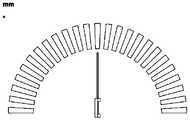
- FIG. 3is a schematic diagram of a calibration graph according to an embodiment of the present application.
- FIG. 4is a schematic diagram of a calibration graph according to an embodiment of the present application.
- FIG. 5is a schematic diagram of the relationship between a two-dimensional indication graph and a calibration graph according to an embodiment of the present application
- FIG. 6is a schematic diagram of the relationship between a two-dimensional indication graphic and a calibration graphic according to an embodiment of the present application
- FIG. 7is a schematic diagram of the relationship between a three-dimensional indication graphic and a calibration graphic according to an embodiment of the present application.
- FIG. 8is a schematic structural diagram of a collaborative robotic arm device according to an embodiment of the present application.
- FIG. 9is a schematic structural diagram of a host part and an optical navigation device according to an embodiment of the present application.
- FIG. 10is a schematic structural diagram of an optical positioning frame according to an embodiment of the present application.
- FIG. 11is a schematic structural diagram of an optical navigation device according to an embodiment of the present application.
- FIG. 12is a schematic structural diagram of an end effector according to an embodiment of the present application.
- FIG. 13is a schematic structural diagram of installing an end positioning frame on an end effector according to an embodiment of the present application.
- FIG. 14is a schematic structural diagram of an end positioning frame according to an embodiment of the present application.
- FIG. 15is a side view of an end positioning frame according to an embodiment of the present application.
- 16is a schematic structural diagram of a pinball mechanism part of an end positioning frame according to an embodiment of the present application.
- 17is a schematic diagram of the positional relationship between the reference frame and the plane to be cut according to an embodiment of the present application.
- 18is a schematic diagram of the positional relationship between the end positioning frame and the body positioning frame according to an embodiment of the present application
- 19is a schematic diagram of the positional relationship between the end effector and the cut target according to an embodiment of the present application.
- Fig. 20is a schematic diagram of a control system for anti-vibration of a saw blade according to an embodiment of the present application
- an embodiment of a control methodis provided. It should be noted that the steps shown in the flowchart of the accompanying drawings may be executed in a computer system such as a set of computer-executable instructions, and although the flowchart A logical order is shown in the figures, but in some cases steps shown or described may be performed in an order different from that herein.
- FIG. 1is a flowchart of a control method according to an embodiment of the present application. As shown in FIG. 1 , the method includes the following steps:
- step S1002the coordinate information of the end of the osteotomy saw blade is obtained, and the coordinate information of the end of the saw blade is calculated according to the position information of a certain point at the end of the saw blade.
- the position information of the point, and the coordinate informationis calculated.
- the center point of the rectanglecan be used as the position information of the tip of the saw blade.
- the NDI Polaris optical positioning and tracking system(NDI, Canada Northern Digital Inc.) records the coordinate system relationship between the body positioning frame of the end effector and the blade tip positioning frame, and corrects the coordinates of the end effector body positioning frame through this coordinate system relationship Tie.
- the spatial pose of the positioning frame of the end effector body captured by the NDI Polaris optical positioning and tracking systemrepresents the spatial position and attitude information of the saw blade.
- the coordinates of the end of the saw bladecan be represented by the coordinate system where the positioning frame of the end effector body is located. Finally, the coordinate information of the saw blade is obtained through the coordinate information of the body positioning frame, and the coordinate information of the end point of the saw blade is calculated through the coordinate information of the saw blade.
- the coordinate information of the end point of the saw bladecan also be calculated in combination with the end positioning frame of the osteotomy saw blade, that is, the end of the osteotomy saw blade is close to the target cutting surface and reaches a predetermined alignment position
- the positional relationship of the coordinate system between the body positioning frame of the end effector and the end positioning frame of the osteotomy saw bladeis obtained.
- the osteotomy saw bladeis mounted on the end effector.
- the pose information of the osteotomy saw bladeis acquired in real time; the coordinate information of the end of the current osteotomy saw blade is obtained through the pose information of the current osteotomy saw blade. In this way, the coordinate information of the tip of the osteotomy saw blade is obtained by calculating these positional relationships.
- the plane of the saw bladeis actually calculated coordinate system corresponding to the target location of the cutting plane C P of the relationship between the coordinate system.
- the calculation of the pose angleis to calculate the angle between the plane where the saw blade is located and the target cutting surface.
- Step S1004establish a relationship between the coordinate information of the end of the osteotomy saw blade and the calibration graph, wherein the calibration graph is a graph with a reference line, and when the end of the osteotomy saw blade overlaps with the target cutting surface, the end of the osteotomy saw blade is The coordinate information of the corresponding indicator is displayed on the screen, the indicator indicates the position of the reference line of the calibration graph, and the indicator feeds back the coordinate information of the end of the osteotomy saw blade in the calibration graph.
- the screenis a display unit capable of correspondingly reflecting the change of the coordinate information of the end of the osteotomy saw blade when the osteotomy saw blade moves.
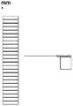
- the calibration graphicscan clearly identify any graphics in the forward and reverse moving directions. It can be a rectangle with different colored squares as shown in Figure 4, or other forms of graphics, as shown in Figures 2 and 3 respectively. Like wifi and radar graphs and sector graphs, these graphs have a center reference line and two directions based on the reference line. The calibration graph can also have only one reference line and only mark the movement of the medical tool in one direction. . This step is to feed back the micro-change of the osteotomy saw blade offset from the plane to be osteotomy during the osteotomy process by calibrating the graph in real time.
- Step S1006Adjust the position of the osteotomy saw blade according to the change of the index mark corresponding to the coordinate information of the end of the osteotomy saw blade and the position of the reference line of the calibration graph, so that the index mark keeps moving within the predetermined range of the reference line.
- the reference lineis used to represent the plane to be osteotomy.
- the indicator in the calibration graphindicates a deviation from the reference line, it means that the position of the osteotomy saw is offset from the plane to be osteotomy.
- the above predetermined rangeis the error range of the allowable deviation of the osteotomy saw blade during osteotomy.
- the above methodcleverly uses visualization to ensure that the offset of the osteotomy saw blade is within a predetermined range, and the real-time control can be fine-tuned according to the visualized observation results at any time, even if the tool is constantly shaking and cutting, The accuracy of the desired cutting position can still be ensured and kept moving within the target plane to be osteotomy, thereby solving the technical problem that the osteotomy saw blade cannot guarantee the cutting position accuracy in real time due to the characteristics of the cooperative manipulator in the related art.
- the indicatorfeeds back the coordinate information of the end of the saw blade in the calibration graph, which can include:
- the direction in which the above-mentioned indication mark moves in the calibration graphindicates the azimuth of the coordinate information of the end of the saw blade from the target cutting surface when the end of the saw blade is on the target to be cut.
- the moving direction of the indicator in the calibration graphis made to correspond to the target orientation, where the target orientation is the coordinate information of the saw blade tip when the saw blade tip is on the target to be cut The bearing from the target cut plane.
- the moving direction of the indicator in the calibration graphis made to correspond to the target orientation, where the target orientation is the distance between the coordinate information of the saw blade end and the target cutting surface when the saw blade end is on the target to be cut.
- the orientationincludes: controlling the indicator mark to move in the forward and reverse directions of the target cutting plane in the calibration graph, wherein the moving directions are respectively the first direction and the second direction relative to the reference line of the calibration graph.
- the first direction and the second directionmay be the upper and lower directions of the reference line of the calibration pattern, respectively.
- the indicator markafter controlling the indicator mark to move in both forward and reverse directions based on the target cutting plane in the calibration graph, it further includes: when the indicator mark indicates the first direction in the calibration graph The actual cutting position of the osteotomy saw blade from the target cutting plane is controlled at a position close to the edge of the patient's bone; when the indicator marks indicate the second direction in the calibration graph, the osteotomy saw blade is distanced from the target cutting plane. The actual cutting position is controlled away from the edge of the patient's bone. In this way, the depth of the osteotomy can be detected in real time, and the deviation of the osteotomy position caused by the misoperation during the osteotomy can be avoided.
- the actual cutting position of the osteotomy saw blade from the target cutting planeis controlled to be close to the edge of the patient's bone; when the indicator indicates the lower part in the calibration graph In this case, the actual cutting position of the osteotomy saw blade from the target cutting plane is controlled at a position away from the edge of the patient's bone.
- the actual cutting position of the saw bladeis reflected by the indication direction of the indication mark.
- the indication markis indicated in the upper part of the calibration graph, it means that the actual cutting position is shallower than the target cutting plane, or the actual cutting position is close to the edge of the patient's bone.
- PositionWhen the indicator is in the lower part of the calibration graph, it means that the actual cutting position is farther from the target cutting plane, or the actual cutting position is far from the edge of the patient's bone.
- the above stepscorrespond to the visualized calibration graphics by controlling the saw blade, so that the visualized calibration graphics can feed back the positional relationship, direction and distance of the offset of the saw blade to the target plane to be osteotomy in real time, and let the calibration graphics feedback the offset of the saw blade to the target to be osteotomy.
- the two directions of the planecan avoid interference in other directions, and can better and more intuitively fine-tune the saw blade in real time to keep it within the predetermined deviation range above and below the plane to be osteotomy, so as to better ensure the operation of the osteotomy saw blade Cutting accuracy.
- before acquiring the coordinate information of the tip of the osteotomy saw bladeit includes: by determining the positional relationship between the position of the tip positioning frame and the target cutting surface, controlling the robotic arm device to move, wherein the tip performs The device is installed on the robotic arm device; judge whether the distance between the end positioning frame and the target cutting surface exceeds the threshold range, if it exceeds the threshold range, update the positional relationship between the position of the end positioning frame and the target cutting surface, and continue to control the robotic arm device The movement is performed until the end of the osteotomy saw blade is close to the target cutting surface and reaches the predetermined alignment position, then the judgment is stopped. In this way, the collaborative robotic arm is controlled to move to the target position.
- the end of the osteotomy saw bladeis close to the target cutting plane, and the plane of the osteotomy saw blade also coincides with the target cutting plane, so as to prepare for the subsequent visualization and fine-tuning.
- the visual fine-tuningis to control the movement of the saw blade in real time within a range of almost less than a millimeter, so the plane where the osteotomy saw blade is located basically coincides with the target cutting surface, that is, the end of the osteotomy saw blade is close to the target cutting surface and reaches the predetermined Align position.
- the robotic arm deviceis connected with a positioning frame or a target reference frame through a flange.
- the positioning frame or target reference frame on the flangeis blocked during osteotomy, it will lead to the delay in obtaining the coordinate information of the end of the saw blade. This will result in a large deviation of the cutting position. It can be visualized and real-time feedback whether the acquisition of the end coordinate information is timely, and whether there is a deviation in the cutting position.
- associating the coordinate information of the end of the saw blade with the calibration graphincludes: when the positioning frame or the target reference frame on the flange on the robotic arm device is blocked during the osteotomy, Then change the color of the calibration graph to prompt.
- associating the coordinate information of the end of the saw blade with the calibration graphicincludes: presetting the calibration graphic as a plurality of regions of different colors, each color region corresponding to a predetermined range of different sizes.
- the calibration graphis preset as five different color areas, wherein each color area corresponds to a predetermined range of different sizes; the indicator marks corresponding to the coordinates of the end of the osteotomy saw blade are controlled to keep them at the benchmark. Move within a small predetermined range around the line.
- the total range of the calibration graphcan be preset to be 5mm, and the upper and lower parts of the calibration graph can be divided into 5 color areas, namely: red, yellow, green, yellow, and red, forming a rainbow bar.
- the range of each color areais 1mm, and each color area is further divided into 5 unit cells, each unit cell represents the unit distance that the indicator moves in the calibration graph, and also represents the actual change of the coordinate information at the end of the saw blade is 0.2mm.
- the third unit cell in the green arearepresents the position of the reference line, and the third cell in the green area also corresponds to the relative relationship between the real saw blade end and the target osteotomy plane, which is an offset of ⁇ 0.1mm, and so on for other cells.
- the third unit cell (reference line) in the green areadivides the calibration graph into two parts.
- the indicatormoves to the top of the calibration graph; when the saw blade osteotomy is deep, the indicator moves Move down the calibration graph.
- the rainbow bardisplays the top red grid or the bottom red grid.
- associating the coordinate information of the end of the osteotomy saw blade with the calibration graphincludes: the unit distance that the preset indicator moves in the calibration graph corresponds to the target coordinate information, and the target coordinate information is the saw blade The coordinate information of the actual change of the end.
- the indicatoris a rectangular bar that can indicate different positions through light and shade changes in the calibration graph, and/or the indicator is a three-dimensional figure corresponding to an osteotomy saw blade, and/or the indicator is a cutting The two-dimensional graphics corresponding to the bone saw blade.
- the indicatoris a rectangular bar that can indicate different positions through light and shade changes in the calibration graph.
- the rectangular bar corresponding to the coordinate informationbecomes brighter at the position of the reference line of the calibration graph (the third grid in the green area).
- the rectangular baris in the calibration graph
- the position of the saw bladeis changed accordingly, and the unit distance of the rectangular bar in the calibration graph means that the coordinate information of the end of the saw blade actually changes by 0.2mm.
- the change of the coordinate informationrepresents the spatial distance that the end of the saw blade deviates from the target cutting surface on the cutting target.
- the above-mentioned rectangular barsmay also be indicators of other shapes, and may also be used as indicators by brightening the unit cells of the color regions divided in the calibration graph.
- the indicatorwhen the indicator is a three-dimensional indicator graphic corresponding to the osteotomy saw blade, the three-dimensional indicator graphic represents the data of the three-dimensional graphic of the actual saw blade, and the corresponding information between the three-dimensional indicator graphic and the actual osteotomy saw blade can be It is obtained by using the reference frame on the end effector and the navigator in a similar way to obtain data information from the end of the saw blade.
- the rectangular block in the middle of the left solid rectanglerepresents the target position of osteotomy.
- the navigation devicecaptures the position and attitude of the positioning frame (end effector positioning frame) in real time, and displays the position and attitude in real time in the 3D view synchronously.
- the specific methodis as follows: referring to FIG. 8 , the positioning frame 500 represents a coordinate system, and the three-dimensional rectangle (the target position for osteotomy) also represents a coordinate system.
- the coordinate systemcan refer to the coordinate system 801 shown in FIG. 17 .
- the pose relationship of the coordinate systemis the pose relationship between the three-dimensional rectangle and the saw blade.
- the end of the three-dimensional indication pattern close to the calibration patternis used as the indication end, and the indication end represents the end of the saw blade; no matter how the three-dimensional indication pattern changes, the indication end of the three-dimensional indication pattern is always within the preset range of the calibration pattern.
- the preset rangecan be Along an edge of the indicating pattern that can indicate a unit distance.
- the change of the coordinate informationrepresents the spatial distance that the end of the saw blade deviates from the target cutting surface on the cutting target.
- the indication markis a two-dimensional indication graphic corresponding to the osteotomy saw blade
- the two-dimensional indication graphicrepresents the two-dimensional data of the actual saw blade.
- the corresponding information between the two-dimensional indication graphics and the actual saw bladecan be obtained by using the reference frame on the end effector and the navigator according to the similar acquisition method of the data information at the end of the saw blade.
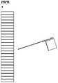
- the three-dimensional rectangular block shown on the left side of Figure 7represents the target cutting surface. The rectangular block will be fixed on the software interface and projected to the back of the rectangular block perpendicular to the cutting surface to form a two-dimensional rectangular strip; the center of the saw blade Lines are also projected to the "back" plane.
- the position of the reference line in the center of the three-dimensional rectangular blockrepresents the target cutting surface, and the angle between the projected target cutting surface (which becomes a line after projection) and the center line of the saw blade on the right side represents the actual saw blade.
- the angle between the plane and the target cutting planeis the angle between the plane and the target cutting plane.
- the indication endrepresents the end of the saw blade; no matter how the indication pattern changes, the indication end of the indication graph is always within the preset range of the calibration graph, for example, the preset range can be along the indication
- the patterncan indicate a unit distance on one edge.
- the indication end corresponding to the coordinate informationis indicated at the position of the reference line of the calibration graph.
- the position of the indication end in the calibration graphchanges accordingly, and the indication end is at
- the unit distance moved in the calibration graphmeans that the coordinate information of the end of the saw blade actually changes by 0.2mm.
- the change of the coordinate informationrepresents the spatial distance that the end of the saw blade deviates from the target cutting surface on the cutting target.
- the methodfurther includes: displaying the actual angle between the plane where the osteotomy saw blade is located and the target cutting plane through the first indication frame.
- the methodfurther includes: displaying the actual change data of the coordinate information of the end of the osteotomy saw blade compared with the target cutting plane through a second indication frame.
- the relationship between the target cutting (osteotomy) surface and the saw bladeis established and tracked in real time, and the user is guided to make adjustments through visualization, so as to obtain the best osteotomy effect, improve the success rate of osteotomy, and the displayed parameters are intuitive, Easy to understand, with a flat learning curve.
- the medical instrument referred to in this applicationrefers to an instrumental device that can be used in medicine and assist doctors in completing examinations or surgical operations, such as a chainsaw and its saw blade used in total knee replacement surgery, but not limited to Here, forceps, drills, milling cutters, screwdrivers, dilators, implant inserters and the like are also possible.
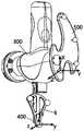
- the robotic arm deviceincludes a control cabinet 100 , a cooperative robotic arm 200 , an end effector 300 , a medical instrument 400 , and an optical positioning frame 500 mounted on the body of the end effector 300 .
- a control unit 103is installed in the control cabinet 100, and the control unit 103 has a signal processing capability, which may be, but is not limited to, including a central processing unit (Central Processing Unit, CPU for short), a network processor (Network Processor, NP for short) , Digital Signal Processor (DSP), Application Specific Integrated Circuit (ASIC), Field Programmable Gate Array (FPGA) or other programmable logic devices, discrete gate or transistor logic devices, discrete hardware components, etc. chip or device.
- a central processing unitCentral Processing Unit, CPU for short
- NPNetwork Processor
- DSPDigital Signal Processor
- ASICApplication Specific Integrated Circuit
- FPGAField Programmable Gate Array
- the control unit 103can be connected with the host part (not shown) of the system through the interface part 101 of the control cabinet 100 to realize the communication with the system host.
- the control unit 103can receive the control signal from the system host and convert it to control the cooperative robotic arm 200 motion operating instructions.
- the collaborative robotic arm 200can receive the instruction from the control unit 103 and move according to the movement mode defined by the instruction, or the operator can apply an external force to the collaborative robotic arm to push, pull, lift, press, etc. under the manual control of the operator. action.
- the top end surface of the control cabinet 100is the base part 102 , and the base part 102 of the control cabinet 100 is fixedly connected with the base end 201 of the cooperative robotic arm 200 .
- the cooperative robotic arm 200is a multi-axis robotic arm, the proximal end of which is the base end 201 , and is fixedly installed at the base portion 102 of the control cabinet 100 .
- the distal end of the collaborative manipulator 200is the flange end 202, and the collaborative manipulator 200 can receive an instruction from the control unit 103, so that the flange end 202 completes rotation, translation and other actions according to the movement mode defined by the command and moves to a certain position defined by the command. a spatial location.
- the flange end 202 of the collaborative robotic arm 200is fixedly connected to the end effector 300, and the end of the end effector 300 carries a medical instrument 400.
- the medical instrument 400 carried on the end effector 300 provided in this embodimentis a chainsaw Saw blade, the saw blade is driven by a chainsaw motor, and the saw blade can maintain a state of high-speed swing during the working process.
- an optical positioning frame 500may also be installed on the body of the end effector 300.
- the systemfurther includes a host part 1000, and the host part may be a computer, or a similar device with storage, calculation, and communication functions.
- the optical navigation device and the system host 1000are integrated on one device. It can be understood that the two can also be set independently, or the system host and the robotic arm device shown in FIG. 8 can be integrated together , as long as a secure connection and stable communication between the devices can be ensured.
- the optical navigation device 600can be a binocular navigation camera, which can track the tracking marks on the optical positioning frame (usually each reflective ball, but it is not limited to this, as long as it is a mark that can be tracked by the binocular navigation camera) position, so as to determine the spatial pose information of the optical positioning frame.
- the optical positioning frameusually each reflective ball, but it is not limited to this, as long as it is a mark that can be tracked by the binocular navigation camera
- the optical navigation device 600is fixed on one end of the cantilever 700 , the other end of the cantilever 700 is fixed on the top of the column 800 , and the bottom of the column 800 is connected to the box body accommodating the host 1000 . Cables for data transmission, communication, and power supply are passed through the column 800, the cantilever 700, and the inner cavity of the box body.
- the cantilever 700can be lifted, rotatably and fixedly connected to the position near the top of the upright column 800 .
- a display unit 900is also fixedly installed on the upper part of the middle of the upright column 800 .
- the display unitmay be a liquid crystal display unit, a cathode ray tube display unit, a neon light display unit, a vacuum fluorescent display unit, an electronic mobile information display unit, a gas discharge display unit, a plasma display unit, or a light emitting diode, electroluminescent materials, fiber optics technology, laser technology, holographic technology, or any other technology for displaying information on a display unit.
- the display unitcan display static or moving information, and the displayed information can be in different languages.
- the fixed position of the display unit 900is preferably at a height that is convenient for the operator to observe.
- the host part 1000receives the data from the optical navigation device 600, completes the calculation of the spatial relationship according to the method steps provided by the present application, and generates motion control instructions, and sends the motion control instructions to the control unit 103 of the robotic arm device, the control unit 103 controls the movement of the collaborative robotic arm 200 in space according to the motion control instruction.
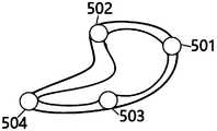
- the main body of the optical positioning frame 500is a flat plate structure, and its outer contour is roughly crescent-shaped; three or more reflective balls are arranged along the edge of the main body at certain intervals for tracking.
- four reflective balls 501 , 502 , 503 , 504are arranged at approximately even intervals at the edge of the main body of the positioning frame, and the surface of each reflective ball is provided with a coating, which can efficiently reflect infrared light.
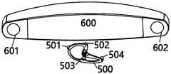
- the optical navigation device 600includes binocular cameras 601 and 602 , and an infrared light emitter is also integrated inside the optical navigation device 600 (not shown), and the infrared emitter Infrared light is emitted externally. After the emitted infrared light is irradiated on the 4 reflective balls on the positioning frame 500, it is reflected by the reflective balls and captured by the binocular camera. Through the triangulation principle, the optical navigation device 600 can calculate the optical positioning frame 500. the spatial pose information.
- the end effector 300includes a body part 301 , and a flange interface end 302 extends from the body part 301 in one direction.
- the flange end 202is fixedly connected.
- a spacer end 305extends out, on which the optical spacer 500 is fixedly mounted; hereinafter referred to as "body spacer", to indicate that the spacer is installed at the end
- the coordinate system where the body spacer is locatedis marked as CF .
- the handle end 303 and the output end 304respectively extend from both sides.
- the handle end 303is held by the operator, so that the operator can directly exert force on the cooperative robotic arm to control the movement of the robotic arm, the end effector and the medical instrument.
- the output end 304is used as the mounting part of the medical instrument.
- a chainsaw blade 400is installed on the output end 304, and the saw blade 400 is fixed in a pluggable manner.
- the electric saw motor (not shown) in the inner cavity of the body part 301drives the saw blade 400 to move according to a predetermined trajectory. During the movement of the saw blade 400 according to the predetermined trajectory, the saw blade 400 also maintains a certain range in the horizontal direction of its sheet-like body. High-speed swing action.
- FIG. 13shows the connection between the end positioning frame 6 and the end effector 300 .
- the body positioning frame 500is fixedly installed at the positioning frame end 305 of the end effector 300
- the coordinate system represented by the positioning frameis CF
- a saw blade 400is fixedly installed
- an end positioning frame 6is installed at the end of the saw blade 400 or a position close to the end, and the coordinate system represented by the positioning frame is C V .
- Fig. 14 and Fig. 15show the detailed structure of the end positioner 6, wherein Fig. 14 is a schematic view of the structure of the end positioner, Fig. 15 is a side view of the end positioner, and the end positioner 6 is based on the end of the medical device
- the end positioning frameincludes a positioning frame body 61 , a card slot 62 , a locking mechanism 63 , and a plurality of reflective balls 7 .
- the end positioning frame body and the end of the medical instrumentcan be easily clamped and fixed, and the optical navigation device can track the positions of the plurality of reflective balls 7 for establishing the end positioning.
- the frame's coordinate system C VThe frame's coordinate system C V .
- the positioning frame body 61is flat, and its overall shape is an approximately inverted triangle with arc edges; the card slot 62 and the locking mechanism 63 are located on one side of the positioning frame body 61 , and the plurality of reflective balls 7 are located on the positioning frame body 61 .
- the number of reflective ballscan be set to 3 to 5, which are respectively arranged near the positions of the three vertices of the roughly triangular positioning frame body 61 .
- the card slot 62is formed as a long slot with two side walls, the locking mechanism 63 is arranged on one side wall forming the card slot 62, and the other side wall forming the card slot 62 is a plane with precision machining and high hardness, as a reference surface for positioning.
- the slot 62is used for inserting the saw blade 400
- the locking mechanism 63is used to abut and fix the saw blade 400 to the reference surface for positioning after the saw blade 400 is inserted, and then the saw blade 400 is clipped and fixed in the slot 62 .
- a locking mechanismis provided on one side wall of the card slot, which can provide the necessary pressure for locking the saw blade stuck in the slot, and abut the saw blade stuck in the slot to the other side wall of the card slot, The positioning accuracy is ensured by the machining accuracy of the other side wall, so that the position of the saw blade can be accurately calculated.
- One end of the saw blade 400 close to the end effectoris provided with a saw blade limit block 401.
- the saw blade limit block 401provides a limit function to limit the edges of the two. The relative position of the saw blade lengthwise.
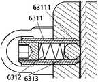
- the locking mechanism 63includes a marble mechanism 631 for providing elastic force for abutting and fixing the saw blade 400 to the reference surface for positioning; the number of the marble mechanism 631 can be one or more.
- the marble mechanismcan be retracted into the side wall of the card slot.
- the marble mechanismextends from the side wall and abuts against the saw with greater pressure On the blade, the fixing of the saw blade.
- the marble mechanism 631includes a accommodating cylinder 6311, a spring 6312 and a marble 6313; There is a through hole, and the accommodating cylinder 6311 is fixed in the through hole; one end of the spring 6312 is fixed at the bottom of the accommodating cylinder 6311 , and the other end of the spring 6312 is connected with the marble 6313 . Through the connection of springs and marbles, it can provide greater pressure for clamping the saw blade.
- One end of the accommodating cylinder 6311 close to the marbles 6313is provided with a marble limiting block 63111 .
- the marble limiting block 63111can limit the position of the marble 6313 in the accommodating cylinder 6311 to prevent the marble 6313 from leaving the accommodating cylinder 6311 under the elastic force of the spring.
- the spring 6312When the saw blade 400 is not inserted, the spring 6312 is in a compressed state in the accommodating cylinder 6311, and the elastic force of the spring 6312 can make the marble 6313 press the opposite side of the side where the through hole is located, that is, the reference surface for positioning, and the marble stopper 63111
- the balls 6313are restricted from being detached from the accommodating cylinder 6311 .
- the spring 6312will be compressed into the accommodating cylinder, thereby leaving a gap in the card slot 62, so that the saw blade 400 is inserted into the card slot 62, and the saw blade 400 is determined to be snapped in place (that is, the saw blade 400 in the length direction).
- the saw blade 400is tightly pressed against the card by the combined action of the spring 6312 and the marble 6313 A reference surface for positioning of the groove 62 .
- the coordinate system where the plurality of reflective balls on the end positioning frame 6 are locatedis defined as C V , since the relative positional relationship between the positioning reference plane forming the card slot 62 and the coordinate system is known.
- C VThe coordinate system where the plurality of reflective balls on the end positioning frame 6 are located.
- the reference frameis fixedly installed on the surface of the target object to be cut, also known as the target reference frame.
- a rigid connectionis formed between the target reference frame and the target object.
- the coordinate system where the reference frame is locatedis C T .
- the target objectis scanned by the optical navigation device to complete the registration. By scanning the reference frame, the spatial relative position of the coordinate system where the reference frame is located and the target object to be cut can be obtained.
- the pseudo-cutting plane of the target object to be cutis set in the host computer, and the coordinate system where the pseudo-cutting plane is located is C P . Since the relative position of the plane to be cut on the target object to be cut is known, and the relative position of the target object to be cut and the reference frame is known, the coordinate system C T where the reference frame is located and the coordinate system C P where the plane to be cut is located can be determined.
- the end spacer 6is provided where the coordinate system C V, the spacer body 500 where coordinate system C F. And the relative positional relationship of C V C F as [RT] FV, while mounting the end of the spacer 6 and the body frame 500 is positioned, the relative positional relationship between the two [RT] FV can be read from the two by the optical navigation device 600 The tracking information of the person is calculated and obtained.
- the pre-positioning phaseincludes the following steps:
- Step 1assemble the medical device and approach the initial position.
- the end effector 300is installed at the end flange 202 of the cooperative robotic arm 200
- the saw blade 400is installed at the saw blade end of the end effector 300
- the end effector 300is further provided with a body positioning frame 500
- the cooperative robotic arm 200is moved by manual drag or machine command control, so that the saw blade 400 is close to the position to be cut, that is, reaches the initial position.
- Step 2install the end positioning bracket.
- the aforementioned end positioning frame 6is clamped to the saw blade 400 to ensure that the saw blade 400 is clamped in place in the slot 62 of the end positioning frame 6.
- one end of the saw blade 400should abut against
- the saw blade 400should abut against the bottom surface of the long groove of the clamping groove 62 .
- end positioning frame 6can also be clamped on the saw blade 400 first, and then the cooperative robotic arm 200 is moved so that the saw blade 400 is close to the position to be cut, that is, the initial position. That is, the sequence of steps S101 and S102 can be replaced.
- Step 3Track and position the end positioning frame.
- the optical navigation devicetracks the positions of the plurality of light-reflecting balls on the end positioning frame 6, and obtains the position information of the coordinate system where the end positioning frame 6 is located by calculation.
- Step 4Calculate the positional relationship between the end positioning frame and the plane to be cut.
- the host partprocesses the position information obtained by the optical navigation device, and calculates and obtains the positional relationship between the coordinate system where the end positioning frame is located and the coordinate system where the plane to be cut is located.
- the optical navigation devicecan observe the saw blade end positioning frame 6 and the target reference frame at the same time.
- the coordinate system where the end positioning frame is locatedis C V
- the coordinate system where the target reference frame is locatedis CT .
- the relative position relationship [RT] VTcan be calculated based on the pose information of the two obtained in the optical navigation device.
- ⁇ [RT] VPC V ⁇ ([RT] TP -1 ⁇ C T ) -1
- the coordinate system C V where the end positioning frame 6 is locatedaccording to the coordinate system C V where the end positioning frame 6 is located, the coordinate system CT where the reference frame is located, and the known positional relationship between the reference frame and the plane to be cut, the coordinate system C V where the end positioning frame 6 is located and the proposed cutting plane can be obtained.
- the positional relationship between the cutting plane of the coordinate system C P [RT] VPthe positional relationship between the cutting plane of the coordinate system C P [RT] VP.
- Step 5Generate a control instruction and send it to the control unit.
- a control instruction for controlling the movement route of the robotic armis generated and sent to the control unit.
- Step 6control the robotic arm to move according to the command. In this step, the robotic arm moves as instructed.
- step 6after the cooperating manipulator completes the movement according to the command, the coordinate system C V where the end positioning frame 6 is located and the coordinate system C P where the cutting plane is located can be completely coincident.
- [RT] VPis the unit Fourth-order matrix E, the end of the saw blade is precisely aligned with the position of the plane to be cut.
- step 6the end position of the medical instrument usually does not accurately reach the position of the planned cutting plane. , therefore, it also includes the following steps:
- Step 7update the tracking position information of the end positioning frame 6 .
- the optical navigation devicecontinues to track the positions of the plurality of reflective balls on the end positioning frame 6, and calculates and obtains the position of the coordinate system where the end positioning frame 6 is located. information to obtain the updated location information.
- Step 8Update and calculate the positional relationship between the end positioning frame and the plane to be cut.
- Step 8With the updated tracking position information of the end positioning frame 6, calculate and update the new positional relationship [RT] VP ′ of the coordinate system C V where the current end positioning frame 6 is located and the coordinate system C P where the plane to be cut is located;
- Step 9Determine whether the positional relationship between the end positioning frame and the plane to be cut exceeds a threshold.
- the difference between the new positional relationship [RT] VP ′ and the unit fourth-order matrix Eis calculated, and the difference between the two is compared with a preset threshold to determine whether the difference exceeds the threshold range.
- step 9If the result of the judgment in step 9 is that the difference exceeds the threshold range, as shown in the figure, return to step 5 to generate a control instruction and send it to the control unit.
- the differenceis that in this step 5, according to the [RT] VP ′ calculated in step 8, a control instruction for controlling the movement route of the robotic arm is generated and sent to the control unit.
- Step S106controlling the robotic arm to complete the movement according to the instruction. After exercising, continue with steps seven to nine.
- Step 10If the result of the judgment in Step 9 is that the difference is less than the threshold range, the system considers that the end of the medical instrument is in place, generates and sends an instruction to stop the movement, ends the pre-positioning stage, and prepares to enter the navigation and positioning stage.
- the positioning frame information reading unitincludes a unit for reading end positioning frame information, and a unit for reading reference frame information, which are respectively used to read the coordinate system C V where the end positioning frame 6 is located from the optical navigation device, and where the reference frame is located. coordinate system C T ;
- the position relationship calculation unitcalculates the position relationship between the coordinate system C V where the end positioning frame 6 is located, and the coordinate system C T where the reference frame is located [RT] VP ;
- the instruction generation unitbased on the position relationship calculated by the position relationship calculation unit, generates a control instruction and sends it to control the movement of the robotic arm;
- the position relationship update unitis used to update and calculate the position relationship [RT] VP ′ between the coordinate system C V where the end positioning frame is located and the coordinate system C P where the plane to be cut is located after the robotic arm moves [RT] VP;
- a judging unitfor judging whether [RT] VP ′ is less than a predetermined threshold, and if it is greater than the predetermined threshold, then update the calculated position relationship [RT] VP ′ according to the position relationship updating unit to generate a control instruction and send it to control the movement of the robotic arm, If less than a predetermined threshold, an instruction to stop motion is generated.
- the systemAfter completing the pre-positioning, the system begins to enter the navigation and positioning stage.
- the navigation and positioning phaseincludes the following steps:
- Step aCalculate and store the positional relationship between the coordinate system where the body spacer is located and the coordinate system where the end spacer is located. After completion of the predetermined bit phase, according to 500 where the optical navigation 600 tracking the obtained apparatus body positioning frame coordinate system C F, and an end spacer 6 location information coordinate system C V is calculated relative positional relation between C V and C F of be [RT] FV and store [RT] FV as the first calibration parameter.
- Step bspacers where the body is calculated based on the first coordinate system and the calibration parameters intended cutting plane in which the positional relationship between the coordinate system of C P.
- the spacer bodyis calculated according to the following equation where the coordinate system 500 and quasi C F C P relationship between the cutting plane of the coordinate system [RT] FP, and [RT] FP stored as the second calibration parameters:
- ⁇ [RT] FP[RT] FV ⁇ C V ⁇ ([RT] TP -1 ⁇ C T ) -1
- Step cremove the end positioning bracket 6 that is clamped at the end of the saw blade.
- Step dset the blocking force parameter.
- the parameters of the blocking force of the collaborative robotic arm 200 during the movementare set, wherein the blocking force in the same plane direction as the plane where the saw blade 400 is located is set to 0, and the blocking force in the same plane direction as the plane where the saw blade 400 is located is set to be perpendicular to the plane where the saw blade 400 is located.
- Step econtrol the saw blade to move according to a predetermined trajectory and track the steps in real time.
- the host partsends an instruction to make the cooperative robotic arm 200 drive the saw blade 400 to move according to a predetermined trajectory.
- the optical navigation device 600tracks and reads the position information of the coordinate system where the body positioning frame 500 is located in real time, and according to the first
- the second calibration parameter [RT] FPis calculated to obtain the real-time position of the tip of the saw blade 400 .
- Step fis calculated in real time the positional relationship between the coordinate system and the coordinate system where the intended cutting plane C P where the blade tip point.
- the coordinate system C T where the reference frame of the target to be cut is locatedand the known positional relationship between the coordinate system where the reference frame is located and the coordinate system where the plane to be cut is located
- the coordinate system C P where the plane to be cut is locatedcan be determined, and the saw blade 400 can be calculated in real time. position of the end plane of the intended positional relationship between the cutting plane of the coordinate system C P.
- Step gjudge whether the distance between the end of the saw blade and the plane to be cut deviates from a predetermined range and give an alarm.
- an alarmwill be issued in various ways such as sound and color display, prompting the operator to intervene and adjust, or the system will automatically respond and adjust, Until all cutting operations in the plane to be cut are completed.
- the present applicationdesigns the host and the control system to also provide the following units:
- the body positioning frame information reading unitis used to read the position information of the coordinate system where the body positioning frame 500 is located from the optical navigation device;
- the calibration parameter calculation unitcalculates the positional relationship [RT] FV of the two ;
- the position relationship calculation unitis based on the position information of the coordinate system where the body positioning frame 500 is located, the position information of the coordinate system CT where the reference frame is located, the calibration parameter [RT] FV , and the known coordinate system where the reference frame is located and the coordinates where the cutting plane is to be located. the positional relationship between the lines, the spacer body 500 obtained by calculation coordinate system C F where the cutting plane of the intended positional relationship between the coordinate system C P [RT] FP;
- the real-time calculation unitis used to calculate and obtain the real-time position of the end of the medical device according to the position information of the coordinate system where the body positioning frame 500 is located and the positional relationship [RT] FP obtained in real time;
- the deviation judgment unitis used to calculate the distance between the plane position of the end of the medical instrument and the coordinate system where the plane to be cut is located, and judge whether the deviation exceeds a predetermined range.
- the method provided by the present applicationfurther includes step h: controlling the medical instrument The end is retracted to the original position.
- the control unitcontrols the movement of the robotic arm 200, so that the saw blade 400 is retracted to a position that is a certain distance away from the target to be cut, for example, it may be the initial position of the previous pre-positioning stage, or it may be different from the previous position The position of the initial position of the pre-positioning stage, as long as the position is relatively close to the target object to be cut and maintains a certain safe distance from the target object.
- step hthe end positioning frame 6 is clamped on the saw blade 400 again, that is, it returns to step 2 of the pre-positioning stage, and continues to perform the above-mentioned steps of the pre-positioning stage and the navigation and positioning stage until the second plane to be cut is completed. cutting operation.
- step 4step 8, and step b and step f, the positional relationship is calculated by using the coordinate system where the second plane to be cut is located.
- the systemdetermines whether there is a third to-be-cut plane, and if so, continues to perform step h, and repeats the above steps until the operations on all the to-be-cut planes are completed. Since multiple planes need to be cut in an operation such as total knee arthroplasty, generally at least 5 different cutting planes are required.
- the solution provided in this embodimentis to return the medical instrument to the initial position after completing the cutting operation of a plane to be cut, and perform pre-positioning and navigation positioning steps again for the next plane to be cut, so as to Ensure accurate positioning of the navigation for each intended cutting plane.
- the solution provided in this embodimentperforms precise pre-positioning before each cutting operation is performed on the target plane to be cut, and records the calibration parameters after the pre-positioning to continue the navigation and positioning, which can eliminate the need for medical instruments every time.
- the positioning error generated during the secondary movementmakes the entire positioning process more refined and provides higher precision.
- the solution provided in this embodimentis completed based on the real-time calculation of the positional relationship between the medical instrument, the end effector, and the target to be cut, it will not consume too much time while ensuring accurate positioning for each plane to be cut. Taking into account the positioning speed and accuracy.
- the embodiment of the present applicationalso provides a control system for anti-vibration of an osteotomy saw blade, and the system can realize its functions through an acquisition unit, a processing unit, and a control unit.
- the anti-vibration control system for an osteotomy saw bladecan be used to implement the anti-vibration control method for an osteotomy saw blade provided by the embodiment of the present application.
- Another anti-vibration control method for an osteotomy saw bladecan also be implemented by the anti-vibration control system for an osteotomy saw blade provided by the embodiment of the present application.
- FIG. 20is a schematic diagram of a control system according to an embodiment of the present application.
- a control system for anti-vibration of an osteotomy saw bladeincludes:
- an obtaining unit 212configured to obtain the coordinate information of the end of the osteotomy saw blade
- the processing unit 214is configured to establish a relationship between the coordinate information of the end of the osteotomy saw blade and the calibration graph, wherein the calibration graph is a graph with a reference line, and when the end of the osteotomy saw blade overlaps with the target cutting surface, the The indication mark corresponding to the coordinate information of the saw blade end on the screen indicates that at the reference line position of the calibration graph, the indication mark feeds back the coordinate information of the end of the osteotomy saw blade in the calibration graph;
- the first control unit 216is used to adjust the position of the osteotomy saw blade according to the change of the index mark corresponding to the coordinate information of the end of the osteotomy saw blade and the position of the reference line of the calibration graph, so that the index mark is kept within the predetermined range of the reference line move within.
- the acquisition unitincludes: a first acquisition module, configured to acquire the body positioning frame of the end effector when the distal end of the osteotomy saw blade is close to the target cutting surface and reaches a predetermined alignment position The positional relationship of the coordinate system with the end positioning frame of the osteotomy saw blade, wherein the osteotomy saw blade is installed on the end effector; the second acquisition module is used for the positional relationship according to the positional relationship of the coordinate system and the position and attitude information of the body positioning frame , obtains the pose information of the osteotomy saw blade in real time; the third acquisition module is used to obtain the coordinate information of the end of the current osteotomy saw blade through the pose information of the current osteotomy saw blade.
- the acquisition unitincludes: a direction control module, configured to make the moving direction of the indicator in the calibration graph correspond to a target orientation, where the target orientation is when the end of the saw blade is on the target to be cut,
- the coordinate information of the tip of the saw bladeis from the orientation of the target cutting surface, that is, the orientation of the tip of the saw blade relative to the target cutting surface.
- the direction control moduleincludes: a first control module, configured to control the indicator mark to move in the forward and reverse directions based on the target cutting plane in the calibration graph, wherein the moving directions are respectively a first direction and a second direction relative to the calibration pattern reference line.
- the first direction and the second directionmay be two directions located at the upper and lower parts of the calibration pattern reference line, respectively.
- the direction control modulefurther includes: a second control module, configured to move the osteotomy saw blade away from the actual cutting plane of the target when the indicator sign indicates the first direction in the calibration graph.
- the cutting positionis controlled at a position close to the edge of the patient's bone;
- the third control moduleis used to control the actual cutting position of the osteotomy saw blade away from the target cutting plane when the indicator marks indicate the second direction in the calibration graph. away from the edge of the patient's bone.
- the first direction and the second directionmay be two directions located at the upper and lower parts of the calibration pattern reference line, respectively.
- the systemfurther includes: a second control unit, configured to control the robotic arm device to move by determining the positional relationship between the position of the end positioning frame and the target cutting surface, wherein the end effector Installed on the robotic arm device; the judgment control unit is used to judge whether the distance between the end positioning frame and the target cutting surface exceeds the threshold range, and if it exceeds the threshold range, update the position of the end positioning frame and the target cutting surface. Continue to control the robotic arm device to move until the end of the osteotomy saw blade is close to the target cutting surface and reaches the predetermined alignment position, then stop judging.
- a second control unitconfigured to control the robotic arm device to move by determining the positional relationship between the position of the end positioning frame and the target cutting surface, wherein the end effector Installed on the robotic arm device
- the judgment control unitis used to judge whether the distance between the end positioning frame and the target cutting surface exceeds the threshold range, and if it exceeds the threshold range, update the position of the end positioning frame and the target cutting surface.
- the first control unitfurther includes: a prompting module for changing the positioning frame or the target reference frame on the flange of the robotic arm device when it is blocked during the osteotomy. The color of the calibration graph is prompted.
- the first control unitfurther includes: a first preset module, configured to preset the calibration graph into a plurality of different color areas, wherein each color area is associated with a predetermined range of different sizes Correspondingly; optionally, the calibration graph can be preset to five different color areas; the fourth control module is used to control the indicator mark corresponding to the coordinates of the end of the osteotomy saw blade to keep it within a predetermined small size around the reference line. move within the range.
- a first preset moduleconfigured to preset the calibration graph into a plurality of different color areas, wherein each color area is associated with a predetermined range of different sizes Correspondingly; optionally, the calibration graph can be preset to five different color areas; the fourth control module is used to control the indicator mark corresponding to the coordinates of the end of the osteotomy saw blade to keep it within a predetermined small size around the reference line. move within the range.
- the processing unitincludes: a second preset module, configured to preset the unit distance that the indicator moves in the calibration graph to correspond to target coordinate information, and the target coordinate information is the end of the saw blade.
- the coordinate information of the actual changeis:
- the systemfurther includes: a first display module, configured to display the actual angle between the plane where the osteotomy saw blade is located and the target cutting plane through the first indication frame.
- systemfurther includes: a second display module, configured to display the actual change data of the coordinate information of the end of the osteotomy saw blade compared with the target cutting plane through the second indication frame.
- a storage mediumincludes a stored program, wherein when the program runs, the device where the storage medium is located is controlled to execute the above method.
- a processoris provided, and the processor includes a program of the processor, wherein when the program runs, a device where the processor is located is controlled to execute the above method.
- control system for anti-vibration of an osteotomy saw bladecorresponds to a control method for anti-vibration of an osteotomy saw blade, so the beneficial effects will not be repeated.
- the disclosed technical contentcan be implemented in other ways.
- the device embodiments described aboveare only illustrative, for example, the division of units may be a logical function division, and there may be other division methods in actual implementation, for example, multiple units or components may be combined or integrated into Another system, or some features can be ignored, or not implemented.
- the shown or discussed mutual coupling or direct coupling or communication connectionmay be through some interfaces, indirect coupling or communication connection of units or modules, and may be in electrical or other forms.
- Units described as separate componentsmay or may not be physically separated, and components shown as units may or may not be physical units, that is, may be located in one place, or may be distributed over multiple units. Some or all of the units may be selected according to actual needs to achieve the purpose of the solution in this embodiment.
- each functional unit in each embodiment of the present applicationmay be integrated into one processing unit, or each unit may exist physically alone, or two or more units may be integrated into one unit.
- the above-mentioned integrated unitsmay be implemented in the form of hardware, or may be implemented in the form of software functional units.
- the integrated unitif implemented as a software functional unit and sold or used as a stand-alone product, may be stored in a computer-readable storage medium.
- the technical solution of the present applicationcan be embodied in the form of a software product in essence, or the part that contributes to the related technology, or all or part of the technical solution, and the computer software product is stored in a storage medium.
- a computer devicewhich may be a personal computer, a server, or a network device, etc.
- the aforementioned storage mediumincludes: U disk, read-only memory (ROM, Read-Only Memory), random access memory (RAM, Random Access Memory), mobile hard disk, magnetic disk or optical disk and other media that can store program codes
Landscapes
- Health & Medical Sciences (AREA)
- Surgery (AREA)
- Life Sciences & Earth Sciences (AREA)
- Biomedical Technology (AREA)
- Medical Informatics (AREA)
- Oral & Maxillofacial Surgery (AREA)
- Dentistry (AREA)
- Engineering & Computer Science (AREA)
- Orthopedic Medicine & Surgery (AREA)
- Heart & Thoracic Surgery (AREA)
- Nuclear Medicine, Radiotherapy & Molecular Imaging (AREA)
- Molecular Biology (AREA)
- Animal Behavior & Ethology (AREA)
- General Health & Medical Sciences (AREA)
- Public Health (AREA)
- Veterinary Medicine (AREA)
- Surgical Instruments (AREA)
Abstract
Description
Translated fromChinese相关申请的交叉引用CROSS-REFERENCE TO RELATED APPLICATIONS
本申请要求享有于2020年07月01日提交的名称为“一种截骨锯片防抖动的控制方法和系统”的中国专利申请202010628902.5的优先权,该申请的全部内容通过引用并入本文中。This application claims the priority of Chinese Patent Application No. 202010628902.5, which was filed on Jul. 1, 2020 and is entitled "An Osteotomy Saw Blade Anti-vibration Control Method and System", the entire contents of which are incorporated herein by reference. middle.
本申请涉及计算机辅助手术技术领域,特别是涉及一种控制方法和系统、存储介质和处理器。The present application relates to the technical field of computer-assisted surgery, and in particular, to a control method and system, a storage medium and a processor.
在计算机辅助的外科手术系统中,通常设置协作机械臂。协作机械臂的远端通常会搭载末端执行器,末端执行器的远端根据不同的场景需要,会搭载不同的医用器械,例如:锯、钻、铣刀等(在本文中,以“近端”表示相对而言更靠近机械臂操作者、更远离患者的一端,以“远端”表示相对而言更远离机械臂操作者、更靠近患者的一端)。通过协作机械臂-末端执行器-医用器械三者之间的机械连接机构和控制操作,实现对目标的切割、钻、研磨等动作,以电锯为例,截骨电锯的锯片是末端执行器较常搭载的医用器械之一,电锯可以较为高效的对目标进行切割,适用于例如全膝关节置换手术等,为了保证操作的精准,锯片的最远端(也可称为前端或末端)位置的精准定位切割是非常重要的;所以在截骨手术这种场景中要求截骨锯片需要保持在特定的待切割的截骨平面内来进行切割,而这种特定的截骨手术场景下通常会存在以下两个问题:In computer-assisted surgical systems, collaborative robotic arms are typically provided. The distal end of the collaborative robotic arm is usually equipped with an end effector, and the distal end of the end effector will be equipped with different medical instruments according to the needs of different scenarios, such as: saws, drills, milling cutters, etc. ” means the end of the arm that is relatively closer to the operator and farther from the patient, and “distal” means the end of the arm that is farther away from the operator and closer to the patient). Through the mechanical connection mechanism and control operation between the cooperative robotic arm-end effector-medical instrument, the cutting, drilling, grinding and other actions of the target are realized. Taking the electric saw as an example, the saw blade of the osteotomy electric saw is the end One of the most commonly used medical instruments in the actuator, the chainsaw can cut the target more efficiently and is suitable for, for example, total knee replacement surgery. The precise positioning of the cutting position (or end) is very important; so in the scenario of osteotomy, the osteotomy saw blade needs to be kept in the specific osteotomy plane to be cut for cutting, and this specific osteotomy There are usually two problems in the surgical scene:
1、协作机械臂与其他类型机械臂的主要区别就是在操作使用协作机械臂时,需要通过人手扶机械臂,直接对机械臂进行推、拉、提、压等操作动作。这种半人工操作势必导致在截骨的时候截骨锯片会偏移待切割的截骨平面。1. The main difference between the collaborative robotic arm and other types of robotic arms is that when operating the collaborative robotic arm, it is necessary to directly push, pull, lift, and press the robotic arm by holding the robotic arm by hand. This semi-manual operation will inevitably cause the osteotomy saw blade to deviate from the osteotomy plane to be cut during the osteotomy.
2、当用于骨科手术操作的特定场景时,由于截骨锯片通常具有较小的尺寸,且切割时协作机械臂本身需要保障一定的活动空间和自由度,无法做成刚性的,电锯锯片在手术过程中一直处于高速摆动状态(锯片的摆动速度高达8800次/分钟),所以当进行骨科手术时,切割的锯片难以实时保证切割位置的精度。2. When used in a specific scene of orthopedic surgery, because the osteotomy saw blade usually has a small size, and the collaborative robotic arm itself needs to ensure a certain movement space and freedom during cutting, it cannot be made into a rigid, chainsaw. The saw blade swings at a high speed during the operation (the swing speed of the saw blade is as high as 8800 times/min), so when performing orthopedic surgery, it is difficult for the cutting saw blade to ensure the accuracy of the cutting position in real time.
相关技术中,针对协作机械臂特性导致截骨锯片难以实时保证切割位置精度的技术问题,目前尚未提出有效的解决方案。In the related art, for the technical problem that it is difficult for the osteotomy saw blade to ensure the cutting position accuracy in real time due to the characteristics of the cooperative manipulator, an effective solution has not yet been proposed.
发明内容SUMMARY OF THE INVENTION
本申请实施例提供了一种锯片防抖动的控制方法和系统、存储介质和处理器。Embodiments of the present application provide a control method and system, a storage medium and a processor for anti-shake of a saw blade.
根据本申请实施例的一个方面,提供了一种锯片防抖动的控制方法,包括:获取锯片末端的坐标信息;将所述锯片末端的坐标信息与校准图形建立联系,其中,所述校准图形是带有基准线的图形,在锯片末端与目标切割面重叠的情况下,所述锯片末端的坐标信息在屏幕中所对应的指示标志指示在所述校准图形的基准线位置处,所述指示标志在所述校准图形中反馈所述锯片末端的坐标信息;根据所述指示标志与所述校准图形的基准线位置的变化,调整所述锯片的位置,使其保持在基准线的预定范围内移动。According to an aspect of the embodiments of the present application, a method for controlling the anti-shake of a saw blade is provided, which includes: acquiring coordinate information of the end of the saw blade; and establishing a relationship between the coordinate information of the end of the saw blade and a calibration graph, wherein all the The calibration graph is a graph with a reference line. When the end of the saw blade overlaps with the target cutting surface, the indicator mark corresponding to the coordinate information of the end of the saw blade on the screen indicates the position of the reference line in the calibration graph. At the position, the index mark feeds back the coordinate information of the end of the saw blade in the calibration graph; according to the change of the index mark and the position of the reference line of the calibration graph, the position of the saw blade is adjusted to keep it Move within a predetermined range of the baseline.
根据本发明实施例的另一方面,还提供了一种锯片防抖动的控制系统,包括:According to another aspect of the embodiments of the present invention, a control system for anti-vibration of a saw blade is also provided, including:
获取单元,用于获取锯片末端的坐标信息;处理单元,用于将所述锯片末端的坐标信息与校准图形建立联系,其中,所述校准图形是带有基准线的图形,在锯片末端与目标切割面重叠的情况下,所述锯片末端在屏幕中所对应的指示标志指示在所述校准图形的基准线位置处,所述指示标志在所述校准图形中反馈所述锯片末端的坐标信息;第一控制单元,用于根据所述锯片末端坐标信息所对应的指示标志与所述校准图形的基准线位置的变化,来调整所述锯片的位置,使其保持在基准线的预定范围内移动。The obtaining unit is used to obtain the coordinate information of the end of the saw blade; the processing unit is used to establish a relationship between the coordinate information of the end of the saw blade and the calibration graph, wherein the calibration graph is a graph with a reference line. In the case where the end overlaps with the target cutting surface, the indicator corresponding to the end of the saw blade on the screen is indicated at the reference line position of the calibration graph, and the indicator feeds back the saw blade in the calibration graph The coordinate information of the end; the first control unit is used to adjust the position of the saw blade according to the change of the indicator mark corresponding to the coordinate information of the end of the saw blade and the position of the reference line of the calibration graph to keep it at move within a predetermined range of the baseline.
根据本发明实施例的另一个方面,还提供给了一种存储介质,所述存储介质上保存有程序,所述程序被运行时执行上所述的方法。According to another aspect of the embodiments of the present invention, a storage medium is also provided, where a program is stored on the storage medium, and the above method is executed when the program is run.
根据本发明实施例的另一个方面,还提供给了一种处理器,所述程序被运行时执行上述的方法。According to another aspect of the embodiments of the present invention, a processor is also provided, and the above method is executed when the program is run.
根据本发明实施例,采用了获取锯片末端的坐标信息;将所述锯片末端的坐标信息与校准图形建立联系,其中,所述校准图形是带有基准线的图形,在锯片末端与目标切割面重叠的情况下,所述锯片末端的坐标信息在屏幕中所对应的指示标志指示在所述校准图形的基准线位置处,所述指示标志在所述校准图形中反馈所述锯片末端的坐标信息;根据所述锯片末端坐标信息所对应的指示标志与所述校准图形的基准线位置的变化,来调整所述锯片的位置,使其保持在基准线的预定范围内移动。通过本发明解决了相关技术中协作机械臂特性导致的锯片难以实时保证切割位置精度的技术问题,使得在医生操作协作机械臂的过程中可以实时对锯片进行微调,从而保证在整个截骨手术切割过程中,锯片均较精准的保持在待截目标平面内进行切割。According to the embodiment of the present invention, the coordinate information of the end of the saw blade is obtained; the coordinate information of the end of the saw blade is connected with a calibration graph, wherein the calibration graph is a graph with a reference line, and the end of the saw blade is connected with the calibration graph. In the case where the target cutting surfaces overlap, the indication mark corresponding to the coordinate information of the saw blade end on the screen is indicated at the reference line position of the calibration graph, and the indication mark feeds back the saw in the calibration graph The coordinate information of the end of the blade; according to the change of the indicator mark corresponding to the coordinate information of the end of the saw blade and the position of the reference line of the calibration pattern, the position of the saw blade is adjusted to keep it within the predetermined range of the reference line. move. The invention solves the technical problem that the saw blade is difficult to ensure the cutting position accuracy in real time due to the characteristics of the collaborative robotic arm in the related art, so that the doctor can fine-tune the saw blade in real time during the process of operating the collaborative robotic arm, thereby ensuring that the entire osteotomy is performed. During the surgical cutting process, the saw blades are kept accurately in the target plane to be cut for cutting.
构成本申请的一部分的附图用来提供对本发明的进一步理解,本发明的示意性实施例及其说明用于解释本发明,并不构成对本发明的不当限定。在附图中:The accompanying drawings constituting a part of the present application are used to provide further understanding of the present invention, and the exemplary embodiments of the present invention and their descriptions are used to explain the present invention and do not constitute an improper limitation of the present invention. In the attached image:
图1是根据本申请实施例的一种锯片防抖动的控制方法的流程图;Fig. 1 is a flow chart of a control method for anti-vibration of a saw blade according to an embodiment of the present application;
图2是根据本申请实施例的校准图形示意图;2 is a schematic diagram of a calibration graph according to an embodiment of the present application;
图3是根据本申请实施例的校准图形示意图;3 is a schematic diagram of a calibration graph according to an embodiment of the present application;
图4是根据本申请实施例的校准图形示意图;4 is a schematic diagram of a calibration graph according to an embodiment of the present application;
图5是根据本申请实施例二维指示图形和校准图形的关系示意图;5 is a schematic diagram of the relationship between a two-dimensional indication graph and a calibration graph according to an embodiment of the present application;
图6是根据本申请实施例二维指示图形和校准图形的关系示意图;6 is a schematic diagram of the relationship between a two-dimensional indication graphic and a calibration graphic according to an embodiment of the present application;
图7是根据本申请实施例三维指示图形和校准图形的关系示意图;7 is a schematic diagram of the relationship between a three-dimensional indication graphic and a calibration graphic according to an embodiment of the present application;
图8为根据本申请实施例一种协作机械臂装置的结构示意图;8 is a schematic structural diagram of a collaborative robotic arm device according to an embodiment of the present application;
图9是根据本申请实施例主机部分和光学导航装置的结构示意图;9 is a schematic structural diagram of a host part and an optical navigation device according to an embodiment of the present application;
图10是根据本申请实施例的光学定位架的结构示意图;10 is a schematic structural diagram of an optical positioning frame according to an embodiment of the present application;
图11是根据本申请实施例光学导航装置的结构示意图;11 is a schematic structural diagram of an optical navigation device according to an embodiment of the present application;
图12是根据本申请实施例末端执行器的结构示意图;12 is a schematic structural diagram of an end effector according to an embodiment of the present application;
图13是根据本申请实施例在末端执行器上安装末端定位架的结构示意图;13 is a schematic structural diagram of installing an end positioning frame on an end effector according to an embodiment of the present application;
图14是根据本申请实施例末端定位架的结构示意图;14 is a schematic structural diagram of an end positioning frame according to an embodiment of the present application;
图15是根据本申请实施例末端定位架的侧视图;FIG. 15 is a side view of an end positioning frame according to an embodiment of the present application;
图16是根据本申请实施例末端定位架的弹珠机构部分的结构示意图;16 is a schematic structural diagram of a pinball mechanism part of an end positioning frame according to an embodiment of the present application;
图17是根据本申请实施例参考架与拟切割平面的位置关系示意图;17 is a schematic diagram of the positional relationship between the reference frame and the plane to be cut according to an embodiment of the present application;
图18是根据本申请实施例末端定位架与本体定位架的位置关系示意图;18 is a schematic diagram of the positional relationship between the end positioning frame and the body positioning frame according to an embodiment of the present application;
图19是根据本申请实施例末端执行器与被切割目标的位置关系示意图;19 is a schematic diagram of the positional relationship between the end effector and the cut target according to an embodiment of the present application;
图20是根据本申请实施例的一种锯片防抖动的控制系统的示意图Fig. 20 is a schematic diagram of a control system for anti-vibration of a saw blade according to an embodiment of the present application
在附图中,附图并未按照实际的比例绘制。In the drawings, the figures are not drawn to actual scale.
为了使本技术领域的人员更好地理解本发明方案,下面将结合本发明实施例中的附图,对本发明实施例中的技术方案进行清楚、完整地描述,显然,所描述的实施例仅仅是本发明一部分的实施例,而不是全部的实施例。基于本发明中的实施例,本领域普通技术人员在没有做出创造性劳动前提下所获得的所有其他实施例,都应当属于本发明保护的范围。In order to make those skilled in the art better understand the solutions of the present invention, the technical solutions in the embodiments of the present invention will be clearly and completely described below with reference to the accompanying drawings in the embodiments of the present invention. Obviously, the described embodiments are only Embodiments are part of the present invention, but not all embodiments. Based on the embodiments of the present invention, all other embodiments obtained by persons of ordinary skill in the art without creative efforts shall fall within the protection scope of the present invention.
需要说明的是,本发明的说明书和权利要求书及上述附图中的术语“第一”、“第二”等是用于区别类似的对象,而不必用于描述特定的顺序或先后次序。应该理解这样使用的数据在适当情况下可以互换,以便这里描述的本发明的实施例能够以除了在这里图示或描述的那些以外的顺序实施。此外,术语“包括”和“具有”以及他们的任何变形,意图在于覆盖不排他的包含,例如,包含了一系列步骤或单元的过程、方法、系统、产品或设备不必限于清楚地列出的那些步骤或单元,而是可包括没有清楚地列出的或对于这些过程、方法、产品或设备固有的其它步骤或单元。It should be noted that the terms "first", "second" and the like in the description and claims of the present invention and the above drawings are used to distinguish similar objects, and are not necessarily used to describe a specific sequence or sequence. It is to be understood that the data so used may be interchanged under appropriate circumstances such that the embodiments of the invention described herein can be practiced in sequences other than those illustrated or described herein. Furthermore, the terms "comprising" and "having" and any variations thereof, are intended to cover non-exclusive inclusion, for example, a process, method, system, product or device comprising a series of steps or units is not necessarily limited to those expressly listed Rather, those steps or units may include other steps or units not expressly listed or inherent to these processes, methods, products or devices.
根据本发明实施例,提供了一种控制方法实施例,需要说明的是,在附图的流程图示出的步骤可以在诸如一组计算机可执行指令的计算机系统中执行,并且,虽然在流程图中示出了逻辑顺序,但是在某些情况下,可以以不同于此处的顺序执行所示出或描述的步骤。According to an embodiment of the present invention, an embodiment of a control method is provided. It should be noted that the steps shown in the flowchart of the accompanying drawings may be executed in a computer system such as a set of computer-executable instructions, and although the flowchart A logical order is shown in the figures, but in some cases steps shown or described may be performed in an order different from that herein.
下面对下列实施例中出现的名词含义进行说明:The noun meanings that appear in the following examples are described below:
图1是根据本申请实施例的一种控制方法的流程图,如图1所示,该方法包括如下步骤:FIG. 1 is a flowchart of a control method according to an embodiment of the present application. As shown in FIG. 1 , the method includes the following steps:
步骤S1002,获取截骨锯片末端的坐标信息,该锯片末端的坐标信息是根据锯片末端某个点的位置信息所计算得到的,具体计算方式可以是从锯片末端的横截面上任意点的位置信息,计算该坐标信息。可选地,当锯片末端的截面是矩形的情况下,矩形的中心点可以作为锯片末端点的位置信息。In step S1002, the coordinate information of the end of the osteotomy saw blade is obtained, and the coordinate information of the end of the saw blade is calculated according to the position information of a certain point at the end of the saw blade. The position information of the point, and the coordinate information is calculated. Optionally, when the cross section of the tip of the saw blade is a rectangle, the center point of the rectangle can be used as the position information of the tip of the saw blade.
为了更加实时准确获得上述步骤中截骨锯片末端的坐标信息,首先经过对刀片(即锯片)与目标切割面的多次递归校准后,当刀片确认对准目标切割面时,可以通过NDI Polaris光学定位跟踪系统(NDI即加拿大Northern Digital Inc.公司)记录位于末端执行器的本体定位架与刀片尖端定位架的坐标系关系,并通过该坐标系关系,修正末端执行器本体定位架的坐标系。此时使用NDI Polaris光学定位跟踪系统拍摄的末端执行器本体定位架的空间位姿,代表锯片的空间位姿信息,锯片末端的坐标可以用末端执行器本体定位架所在坐标系表示。最后是通过本体定位架的坐标信息得到锯片的坐标信息,通过锯片的坐标信息计算锯片末端点的坐标信息。In order to obtain the coordinate information of the end of the osteotomy saw blade in the above steps more accurately in real time, after multiple recursive calibrations of the blade (ie the saw blade) and the target cutting surface, when the blade is confirmed to be aligned with the target cutting surface, it can pass the NDI Polaris optical positioning and tracking system (NDI, Canada Northern Digital Inc.) records the coordinate system relationship between the body positioning frame of the end effector and the blade tip positioning frame, and corrects the coordinates of the end effector body positioning frame through this coordinate system relationship Tie. At this time, the spatial pose of the positioning frame of the end effector body captured by the NDI Polaris optical positioning and tracking system represents the spatial position and attitude information of the saw blade. The coordinates of the end of the saw blade can be represented by the coordinate system where the positioning frame of the end effector body is located. Finally, the coordinate information of the saw blade is obtained through the coordinate information of the body positioning frame, and the coordinate information of the end point of the saw blade is calculated through the coordinate information of the saw blade.
在一种可选的实施方式中,还可以结合截骨锯片的末端定位架计算锯片末端点的坐标信息,即,在截骨锯片的末端靠近目标切割面,并且到达预定对准位置的情况下,获取末端执行器的本体定位架与截骨锯片的末端定位架之间的坐标系位置关系。其中,截骨锯片安装在末端执行器上。根据获取的坐标系位置关系和本体定位架的位姿信息,实时获取截骨锯片的位姿信息;通过当前截骨锯片的位姿信息得到当前截骨 锯片末端的坐标信息。这样,通过计算上述这些位置关系获得截骨锯片末端的坐标信息。In an optional embodiment, the coordinate information of the end point of the saw blade can also be calculated in combination with the end positioning frame of the osteotomy saw blade, that is, the end of the osteotomy saw blade is close to the target cutting surface and reaches a predetermined alignment position In the case of , the positional relationship of the coordinate system between the body positioning frame of the end effector and the end positioning frame of the osteotomy saw blade is obtained. Among them, the osteotomy saw blade is mounted on the end effector. According to the obtained position relationship of the coordinate system and the pose information of the body positioning frame, the pose information of the osteotomy saw blade is acquired in real time; the coordinate information of the end of the current osteotomy saw blade is obtained through the pose information of the current osteotomy saw blade. In this way, the coordinate information of the tip of the osteotomy saw blade is obtained by calculating these positional relationships.
目标切割面所在坐标系CP和待切割目标参考架所在坐标系CT的位置关系,自始至终都是固定的(可以是重合也可以具有固定的位置关系),因此根据待切割目标参考架所在坐标系CT、以及已知的待切割目标参考架所在坐标系CT与目标切割面所在坐标系CP的位置关系,可确定目标切割面所在坐标系CP。Cutting surface target location coordinate relation CP to be cut and the target coordinate reference frame where CT, first and last are fixed (may overlap may have a fixed positional relationship), and therefore the target coordinates from the reference frame to be cut is located CT system, and the known reference frame to be cut and the target location coordinates and the target cutting plane CT where CP positional relationship of the coordinate system, to determine the destination where the cutting plane coordinate system CP.
当实时计算锯片末端点与目标切割面的距离时,实际是计算锯片所在平面对应的坐标系与目标切割面所在坐标系CP的位置关系。而计算位姿角度是计算锯片所在平面和目标切割面之间的角度。When the distance from the blade tip and a target real-time calculation of the cutting plane, the plane of the saw blade is actually calculated coordinate system corresponding to the target location of the cutting plane CP of the relationship between the coordinate system. The calculation of the pose angle is to calculate the angle between the plane where the saw blade is located and the target cutting surface.
步骤S1004,将截骨锯片末端的坐标信息与校准图形建立联系,其中,校准图形是带有基准线的图形,在截骨锯片末端与目标切割面重叠的情况下,截骨锯片末端的坐标信息在屏幕中显示所对应的指示标志,该指示标志指示在校准图形的基准线位置处,指示标志在校准图形中反馈截骨锯片末端的坐标信息。屏幕是能够在截骨锯片移动时,对应地反映截骨锯片末端的坐标信息变化的显示单元。Step S1004, establish a relationship between the coordinate information of the end of the osteotomy saw blade and the calibration graph, wherein the calibration graph is a graph with a reference line, and when the end of the osteotomy saw blade overlaps with the target cutting surface, the end of the osteotomy saw blade is The coordinate information of the corresponding indicator is displayed on the screen, the indicator indicates the position of the reference line of the calibration graph, and the indicator feeds back the coordinate information of the end of the osteotomy saw blade in the calibration graph. The screen is a display unit capable of correspondingly reflecting the change of the coordinate information of the end of the osteotomy saw blade when the osteotomy saw blade moves.
校准图形可以清楚的标识正反两个移动方向的任意图形,可以是如图4所示的带有不同彩色方块组成的矩形,也可以是其他形式的图形,如图2、3分别所示的如wifi和雷达一样的图形和扇形图,这些图形均有中心基准线和以基准线为准的两个方向,校准图形也可以是只有一个基准线,并只在一个方向上标识医疗工具的运动。该步骤是通过校准图形实时反馈截骨锯片在截骨过程中偏移待截骨平面的微变化。The calibration graphics can clearly identify any graphics in the forward and reverse moving directions. It can be a rectangle with different colored squares as shown in Figure 4, or other forms of graphics, as shown in Figures 2 and 3 respectively. Like wifi and radar graphs and sector graphs, these graphs have a center reference line and two directions based on the reference line. The calibration graph can also have only one reference line and only mark the movement of the medical tool in one direction. . This step is to feed back the micro-change of the osteotomy saw blade offset from the plane to be osteotomy during the osteotomy process by calibrating the graph in real time.
步骤S1006,根据截骨锯片末端坐标信息所对应的指示标志与校准图形的基准线位置的变化,来调整截骨锯片的位置,使指示标志保持在基准线的预定范围内移动。以基准线代表待截骨的平面,当校准图形中的指示标指示偏移基准线时,代表截骨锯片的位置偏移了所要截骨的平面。上述预定范围就是截骨锯片在截骨时允许偏移的误差范围。Step S1006: Adjust the position of the osteotomy saw blade according to the change of the index mark corresponding to the coordinate information of the end of the osteotomy saw blade and the position of the reference line of the calibration graph, so that the index mark keeps moving within the predetermined range of the reference line. The reference line is used to represent the plane to be osteotomy. When the indicator in the calibration graph indicates a deviation from the reference line, it means that the position of the osteotomy saw is offset from the plane to be osteotomy. The above predetermined range is the error range of the allowable deviation of the osteotomy saw blade during osteotomy.
上述方法巧妙的利用可视化,来保证截骨锯片的偏移待截骨平面处在预定范围内,可以随时根据可视化的观察结果来进行实时控制的微调,即使刀具在一直不停地抖动切割,依然可以保证所要切割位置的准确度,使其保持在待截骨目标平面内移动,从而解决了相关技术中协作机械臂特性导致的截骨锯片难以实时保证切割位置精度的技术问题。The above method cleverly uses visualization to ensure that the offset of the osteotomy saw blade is within a predetermined range, and the real-time control can be fine-tuned according to the visualized observation results at any time, even if the tool is constantly shaking and cutting, The accuracy of the desired cutting position can still be ensured and kept moving within the target plane to be osteotomy, thereby solving the technical problem that the osteotomy saw blade cannot guarantee the cutting position accuracy in real time due to the characteristics of the cooperative manipulator in the related art.
指示标志在校准图形中反馈锯片末端的坐标信息,具体可以包括:The indicator feeds back the coordinate information of the end of the saw blade in the calibration graph, which can include:
使上述指示标志在校准图形中移动的方向,表示锯片末端在待切割目标上时,锯片末端的坐标信息距离目标切割面的方位。在一种可选的实施方式中,即,首先,使指示标志在校准图形中的移动方向与目标方位相对应,该目标方位为锯片末端在待切割目标上时,锯片末端的坐标信息距离目标切割面的方位。The direction in which the above-mentioned indication mark moves in the calibration graph indicates the azimuth of the coordinate information of the end of the saw blade from the target cutting surface when the end of the saw blade is on the target to be cut. In an optional implementation manner, that is, first, the moving direction of the indicator in the calibration graph is made to correspond to the target orientation, where the target orientation is the coordinate information of the saw blade tip when the saw blade tip is on the target to be cut The bearing from the target cut plane.
在一种可选的实施方式中,使指示标志在校准图形中的移动方向与目标方位相对应,该目标方位为锯片末端在待切割目标上时,锯片末端的坐标信息距离目标切割面的方位,包括:控制指示标志在校准图形中以目标切割面为基准的正反两个方向进行移动,其中,移动方向分别是相对于所述校准图形基准线的第一方向和第二方向。可选的,该第一方向和第二方向可以分别是位于校准图形基准线的上部和下部方向。In an optional embodiment, the moving direction of the indicator in the calibration graph is made to correspond to the target orientation, where the target orientation is the distance between the coordinate information of the saw blade end and the target cutting surface when the saw blade end is on the target to be cut. The orientation includes: controlling the indicator mark to move in the forward and reverse directions of the target cutting plane in the calibration graph, wherein the moving directions are respectively the first direction and the second direction relative to the reference line of the calibration graph. Optionally, the first direction and the second direction may be the upper and lower directions of the reference line of the calibration pattern, respectively.
在一种可选的实施方式中,控制指示标志在校准图形中以目标切割面为基准的正 反两个方向进行移动之后,还包括:当指示标志指示在校准图形中的第一方向的情况下,将截骨锯片距离目标切割平面的实际切割位置,控制在靠近患者骨骼边缘的位置;当指示标志指示在校准图形中的第二方向的情况下,将截骨锯片距离目标切割平面的实际切割位置,控制在远离患者骨骼边缘的位置。通过该方式可以实时检测到截骨的深浅,避免截骨时误操作导致截骨位置的偏差。例如,当指示标志指示在校准图形中的上部的情况下,将截骨锯片距离目标切割平面的实际切割位置,控制在靠近患者骨骼边缘的位置;当指示标志指示在校准图形中的下部的情况下,将截骨锯片距离目标切割平面的实际切割位置,控制在远离患者骨骼边缘的位置。通过指示标志的指示方向反映锯片的实际切割位置,当指示标志指示在校准图形中的上部,表示实际切割的位置距离目标切割平面的位置较浅,或者实际切割的位置在靠近患者骨骼边缘的位置;当指示标志指示在校准图形中的下部,表示实际切割的位置距离目标切割平面的位置较深,或者实际切割的位置在远离患者骨骼边缘的位置。In an optional implementation manner, after controlling the indicator mark to move in both forward and reverse directions based on the target cutting plane in the calibration graph, it further includes: when the indicator mark indicates the first direction in the calibration graph The actual cutting position of the osteotomy saw blade from the target cutting plane is controlled at a position close to the edge of the patient's bone; when the indicator marks indicate the second direction in the calibration graph, the osteotomy saw blade is distanced from the target cutting plane. The actual cutting position is controlled away from the edge of the patient's bone. In this way, the depth of the osteotomy can be detected in real time, and the deviation of the osteotomy position caused by the misoperation during the osteotomy can be avoided. For example, when the indicator indicates the upper part in the calibration graph, the actual cutting position of the osteotomy saw blade from the target cutting plane is controlled to be close to the edge of the patient's bone; when the indicator indicates the lower part in the calibration graph In this case, the actual cutting position of the osteotomy saw blade from the target cutting plane is controlled at a position away from the edge of the patient's bone. The actual cutting position of the saw blade is reflected by the indication direction of the indication mark. When the indication mark is indicated in the upper part of the calibration graph, it means that the actual cutting position is shallower than the target cutting plane, or the actual cutting position is close to the edge of the patient's bone. Position: When the indicator is in the lower part of the calibration graph, it means that the actual cutting position is farther from the target cutting plane, or the actual cutting position is far from the edge of the patient's bone.
上述步骤通过控制锯片与可视化的校准图形对应,使可视化的校准图形实时反馈锯片偏移待截骨目标平面的位置关系、方向和距离,并且让校准图形反馈锯片偏移待截骨目标平面的两个方向,避免其他方向上的干扰,能够更好更加直观并实时微调锯片使其保持在待截骨平面上下预定的偏差范围之内,从而更好的保证截骨锯片的手术切割精度。The above steps correspond to the visualized calibration graphics by controlling the saw blade, so that the visualized calibration graphics can feed back the positional relationship, direction and distance of the offset of the saw blade to the target plane to be osteotomy in real time, and let the calibration graphics feedback the offset of the saw blade to the target to be osteotomy. The two directions of the plane can avoid interference in other directions, and can better and more intuitively fine-tune the saw blade in real time to keep it within the predetermined deviation range above and below the plane to be osteotomy, so as to better ensure the operation of the osteotomy saw blade Cutting accuracy.
在一种可选的实施方式中,获取截骨锯片末端的坐标信息之前包括:通过确定末端定位架的位置与目标切割面之间的位置关系,控制机械臂装置进行运动,其中,末端执行器安装在机械臂装置上;判断末端定位架与目标切割面的距离是否超出阈值范围,如果超出阈值范围,则更新末端定位架的位置与目标切割面之间的位置关系,继续控制机械臂装置进行运动,直至在截骨锯片的末端靠近目标切割面并到达预定对准位置的情况下,则停止判断。通过该方式控制协作机械臂的移动到目标位置,此时截骨锯片的末端靠近对准目标切割面,截骨锯片所在的平面也与目标切割面重合,从而为后续的可视化微调做准备,因为可视化微调是实时控制锯片在几乎不到毫米级的范围内移动,所以需要截骨锯片所在平面与目标切割面基本重合,也就是截骨锯片的末端靠近目标切割面并到达预定对准位置。In an optional implementation manner, before acquiring the coordinate information of the tip of the osteotomy saw blade, it includes: by determining the positional relationship between the position of the tip positioning frame and the target cutting surface, controlling the robotic arm device to move, wherein the tip performs The device is installed on the robotic arm device; judge whether the distance between the end positioning frame and the target cutting surface exceeds the threshold range, if it exceeds the threshold range, update the positional relationship between the position of the end positioning frame and the target cutting surface, and continue to control the robotic arm device The movement is performed until the end of the osteotomy saw blade is close to the target cutting surface and reaches the predetermined alignment position, then the judgment is stopped. In this way, the collaborative robotic arm is controlled to move to the target position. At this time, the end of the osteotomy saw blade is close to the target cutting plane, and the plane of the osteotomy saw blade also coincides with the target cutting plane, so as to prepare for the subsequent visualization and fine-tuning. , because the visual fine-tuning is to control the movement of the saw blade in real time within a range of almost less than a millimeter, so the plane where the osteotomy saw blade is located basically coincides with the target cutting surface, that is, the end of the osteotomy saw blade is close to the target cutting surface and reaches the predetermined Align position.
机械臂装置上通过法兰连接有定位架或目标参考架,当该法兰上的定位架或目标参考架在截骨时被遮挡的情况下,会导致锯片末端坐标信息的获取不及时,从而会导致较大切割位置偏差。可以通过可视化实时反馈末端坐标信息的获取是否及时,反映切割位置是否产生偏差。在一种可选的实施方式中,将锯片末端的坐标信息与校准图形建立联系包括:当机械臂装置上的法兰上的定位架或目标参考架在截骨时被遮挡的情况下,则改变校准图形的颜色进行提示。The robotic arm device is connected with a positioning frame or a target reference frame through a flange. When the positioning frame or target reference frame on the flange is blocked during osteotomy, it will lead to the delay in obtaining the coordinate information of the end of the saw blade. This will result in a large deviation of the cutting position. It can be visualized and real-time feedback whether the acquisition of the end coordinate information is timely, and whether there is a deviation in the cutting position. In an optional implementation manner, associating the coordinate information of the end of the saw blade with the calibration graph includes: when the positioning frame or the target reference frame on the flange on the robotic arm device is blocked during the osteotomy, Then change the color of the calibration graph to prompt.
在一种可选的实施方式中,将锯片末端的坐标信息与校准图形建立联系包括:将校准图形预设为多个不同颜色的区域,每个颜色区域与不同大小的预定范围相对应。可选的,将校准图形预设为五个不同的颜色区域,其中,每个颜色区域与不同大小的预定范围相对应;控制截骨锯片末端坐标所对应的指示标志,使其保持在基准线周围小的预定范围内移动。In an optional implementation manner, associating the coordinate information of the end of the saw blade with the calibration graphic includes: presetting the calibration graphic as a plurality of regions of different colors, each color region corresponding to a predetermined range of different sizes. Optionally, the calibration graph is preset as five different color areas, wherein each color area corresponds to a predetermined range of different sizes; the indicator marks corresponding to the coordinates of the end of the osteotomy saw blade are controlled to keep them at the benchmark. Move within a small predetermined range around the line.
可选地,可以预设该校准图形的总量程为5mm,将校准图形的上部至而下部分为5个颜色区域,分别为:红色、黄色、绿色、黄色、红色,形成彩虹条,每个颜色的区域量程为1mm,每种颜色区域再分为5个单位格,每个单位格代表指示标志在校准图形中移动的单位距离,也代表锯片末端的坐标信息实际变化量为0.2mm。其中,绿色区域的第三个单位格代表基准线的位置,绿色区域的第三格同时对应代表真实锯片末 端和目标截骨平面的相对关系为偏移±0.1mm,其它格以此类推。绿色区域的第三个单位格(基准线)将校准图形分为两部分,当锯片截骨截浅了时,指示标志向校准图形上方移动;当锯片截骨截深了时,指示标志向校准图形下方移动。当真实截骨锯片和截骨平面的距离超过总量程±2.5mm时,彩虹条显示红色最上一格或红色最下一格。在一种可选的实施方式中,将截骨锯片末端的坐标信息与校准图形建立联系包括:预设指示标志在校准图形中移动的单位距离与目标坐标信息相对应,目标坐标信息为锯片末端的实际变化的坐标信息。Optionally, the total range of the calibration graph can be preset to be 5mm, and the upper and lower parts of the calibration graph can be divided into 5 color areas, namely: red, yellow, green, yellow, and red, forming a rainbow bar. The range of each color area is 1mm, and each color area is further divided into 5 unit cells, each unit cell represents the unit distance that the indicator moves in the calibration graph, and also represents the actual change of the coordinate information at the end of the saw blade is 0.2mm. Among them, the third unit cell in the green area represents the position of the reference line, and the third cell in the green area also corresponds to the relative relationship between the real saw blade end and the target osteotomy plane, which is an offset of ±0.1mm, and so on for other cells. The third unit cell (reference line) in the green area divides the calibration graph into two parts. When the saw blade osteotomy is shallow, the indicator moves to the top of the calibration graph; when the saw blade osteotomy is deep, the indicator moves Move down the calibration graph. When the distance between the real osteotomy saw blade and the osteotomy plane exceeds the total range of ±2.5mm, the rainbow bar displays the top red grid or the bottom red grid. In an optional embodiment, associating the coordinate information of the end of the osteotomy saw blade with the calibration graph includes: the unit distance that the preset indicator moves in the calibration graph corresponds to the target coordinate information, and the target coordinate information is the saw blade The coordinate information of the actual change of the end.
在一种可选的实施方式中:指示标志是在校准图形中能够通过明暗变化指示不同位置的矩形条,和/或指示标志是截骨锯片对应的三维图形,和/或指示标志是截骨锯片对应的二维图形。指示标志是能够在校准图形中通过明暗变化指示不同位置的矩形条的情况下,当锯片确认对准目标切割面时,近似于锯片末端点与目标切割面重叠,将锯片末端的坐标信息,也就是末端执行器本体定位架的坐标信息(位姿信息)发送到主机,主机将该坐标信息与校准图形建立联系。当锯片末端与目标切割面重叠时,该坐标信息所对应的矩形条在校准图形的基准线位置处(绿色区域的第三格)变亮,当该坐标信息变化时,矩形条在校准图形中的位置做相应变化,矩形条在校准图形中的单位距离代表锯片末端的坐标信息实际变化了0.2mm。该坐标信息的变化表示锯片末端在切割目标上偏离目标切割面的空间距离。上述矩形条也可以是其他形状的指示标记,还可以通过将校准图形中所划分的颜色区域的单位格变明亮的显示来作为指示。In an optional implementation manner: the indicator is a rectangular bar that can indicate different positions through light and shade changes in the calibration graph, and/or the indicator is a three-dimensional figure corresponding to an osteotomy saw blade, and/or the indicator is a cutting The two-dimensional graphics corresponding to the bone saw blade. The indicator is a rectangular bar that can indicate different positions through light and shade changes in the calibration graph. When the saw blade is confirmed to be aligned with the target cutting surface, it is approximated that the end point of the saw blade overlaps the target cutting surface, and the coordinates of the end of the saw blade are calculated. Information, that is, the coordinate information (position and attitude information) of the positioning frame of the end effector body is sent to the host, and the host establishes a link between the coordinate information and the calibration graphic. When the end of the saw blade overlaps with the target cutting surface, the rectangular bar corresponding to the coordinate information becomes brighter at the position of the reference line of the calibration graph (the third grid in the green area). When the coordinate information changes, the rectangular bar is in the calibration graph The position of the saw blade is changed accordingly, and the unit distance of the rectangular bar in the calibration graph means that the coordinate information of the end of the saw blade actually changes by 0.2mm. The change of the coordinate information represents the spatial distance that the end of the saw blade deviates from the target cutting surface on the cutting target. The above-mentioned rectangular bars may also be indicators of other shapes, and may also be used as indicators by brightening the unit cells of the color regions divided in the calibration graph.
如图7所示,当指示标志是截骨锯片对应的三维指示图形的情况下,三维指示图形代表实际锯片的三维图形的数据,三维指示图形与实际截骨锯片的对应信息,可以利用末端执行器上的参考架与导航仪根据锯片末端数据信息类似的获取方式得到。As shown in FIG. 7 , when the indicator is a three-dimensional indicator graphic corresponding to the osteotomy saw blade, the three-dimensional indicator graphic represents the data of the three-dimensional graphic of the actual saw blade, and the corresponding information between the three-dimensional indicator graphic and the actual osteotomy saw blade can be It is obtained by using the reference frame on the end effector and the navigator in a similar way to obtain data information from the end of the saw blade.
左侧立体矩形的中间的那一个矩形块代表截骨目标位置。当锯片对准拟截骨的平面目标时,在三维视图中,锯片就正对着中间的矩形块。截骨过程中,导航设备实时捕获定位架(末端执行器定位架)的位置和姿态,并在三维视图中同步实时的显示该位置和姿态。具体方法为:参考图8所示,定位架500代表一个坐标系,立体矩形(拟截骨的目标位置)也代表一个坐标系,该坐标系可参考图17所示坐标系801,这两个坐标系的位姿关系即为立体矩形和锯片的位姿关系。The rectangular block in the middle of the left solid rectangle represents the target position of osteotomy. When the saw blade is aligned with the flat target to be osteotomy, in the 3D view, the saw blade is directly facing the middle rectangular block. During the osteotomy process, the navigation device captures the position and attitude of the positioning frame (end effector positioning frame) in real time, and displays the position and attitude in real time in the 3D view synchronously. The specific method is as follows: referring to FIG. 8 , the
三维指示图形靠近校准图形的一端作为指示端,指示端代表锯片的末端;无论三维指示图形如何变化,三维指示图形的指示端始终位于校准图形的预设范围内,比如,预设范围可以是沿着指示图案能够指示单位距离的一条边上。当锯片末端与目标切割面重叠时,该坐标信息所对应的指示端指示在校准图形的基准线位置处,当该坐标信息变化时,指示端在校准图形中的位置做相应变化,指示端在校准图形中移动的单位距离可以对应代表锯片末端的坐标信息实际变化了0.2mm。该坐标信息的变化表示锯片末端在切割目标上偏离目标切割面的空间距离。通过三维图形,可以实时观测到锯片整体所在平面与待切割目标的拟切割平面的角度变化,便于调整。The end of the three-dimensional indication pattern close to the calibration pattern is used as the indication end, and the indication end represents the end of the saw blade; no matter how the three-dimensional indication pattern changes, the indication end of the three-dimensional indication pattern is always within the preset range of the calibration pattern. For example, the preset range can be Along an edge of the indicating pattern that can indicate a unit distance. When the end of the saw blade overlaps with the target cutting surface, the indication end corresponding to the coordinate information is indicated at the position of the reference line of the calibration graph. When the coordinate information changes, the position of the indication end in the calibration graph changes accordingly. The unit distance moved in the calibration graph can actually change 0.2mm corresponding to the coordinate information representing the end of the saw blade. The change of the coordinate information represents the spatial distance that the end of the saw blade deviates from the target cutting surface on the cutting target. Through the three-dimensional graphics, the angle change between the plane where the entire saw blade is located and the intended cutting plane of the target to be cut can be observed in real time, which is convenient for adjustment.
如图5和图6所示,指示标志是截骨锯片对应的二维指示图形,该二维指示图形代表实际锯片的二维数据。二维指示图形与实际锯片的对应信息,可以利用末端执行器上的参考架与导航仪根据锯片末端数据信息类似的获取方式得到。图7左侧所示的三维矩形块代表目标切割面,该矩形块会被固定在软件界面上,向矩形块的垂直于切割面的背面进行投影,形成二维的矩形条;锯片的中心线也向“背面”平面投影。三维矩形块中心的基准线位置处代表目标切割面,投影后的目标切割面(投影后就变成线了)和右侧的锯片中心线的两条线的角度,代表了实际锯片的所在平面与目标切割面的角度。As shown in FIG. 5 and FIG. 6 , the indication mark is a two-dimensional indication graphic corresponding to the osteotomy saw blade, and the two-dimensional indication graphic represents the two-dimensional data of the actual saw blade. The corresponding information between the two-dimensional indication graphics and the actual saw blade can be obtained by using the reference frame on the end effector and the navigator according to the similar acquisition method of the data information at the end of the saw blade. The three-dimensional rectangular block shown on the left side of Figure 7 represents the target cutting surface. The rectangular block will be fixed on the software interface and projected to the back of the rectangular block perpendicular to the cutting surface to form a two-dimensional rectangular strip; the center of the saw blade Lines are also projected to the "back" plane. The position of the reference line in the center of the three-dimensional rectangular block represents the target cutting surface, and the angle between the projected target cutting surface (which becomes a line after projection) and the center line of the saw blade on the right side represents the actual saw blade. The angle between the plane and the target cutting plane.
指示图形靠近校准图形的一端作为指示端,指示端代表锯片的末端;无论指示图案如何变化,指示图形的指示端始终位于校准图形的预设范围内,比如,预设范围可以是沿着指示图案能够指示单位距离的一条边上。当锯片末端与目标切割面重叠时,该坐标信息所对应的指示端指示在校准图形的基准线位置处,当该坐标信息变化时指示端在校准图形中的位置做相应变化,指示端在校准图形中移动的单位距离代表锯片末端的坐标信息实际变化了0.2mm。该坐标信息的变化表示锯片末端在切割目标上偏离目标切割面的空间距离。通过二维图形可以实时观测到锯片整体与目标切割面的角度变化,便于调整。One end of the indication graph close to the calibration graph is used as the indication end, and the indication end represents the end of the saw blade; no matter how the indication pattern changes, the indication end of the indication graph is always within the preset range of the calibration graph, for example, the preset range can be along the indication The pattern can indicate a unit distance on one edge. When the end of the saw blade overlaps with the target cutting surface, the indication end corresponding to the coordinate information is indicated at the position of the reference line of the calibration graph. When the coordinate information changes, the position of the indication end in the calibration graph changes accordingly, and the indication end is at The unit distance moved in the calibration graph means that the coordinate information of the end of the saw blade actually changes by 0.2mm. The change of the coordinate information represents the spatial distance that the end of the saw blade deviates from the target cutting surface on the cutting target. Through the two-dimensional graphics, the angle change between the entire saw blade and the target cutting surface can be observed in real time, which is easy to adjust.
在一种可选的实施方式中,获取截骨锯片末端的坐标信息之后还包括:通过第一指示框,显示截骨锯片所在平面与目标切割平面的实际角度。In an optional implementation manner, after acquiring the coordinate information of the end of the osteotomy saw blade, the method further includes: displaying the actual angle between the plane where the osteotomy saw blade is located and the target cutting plane through the first indication frame.
在一种可选的实施方式中,获取截骨锯片末端的坐标信息之后还包括:通过第二指示框,显示截骨锯片末端与目标切割平面相比的坐标信息实际变化数据。In an optional implementation manner, after acquiring the coordinate information of the end of the osteotomy saw blade, the method further includes: displaying the actual change data of the coordinate information of the end of the osteotomy saw blade compared with the target cutting plane through a second indication frame.
该实施例实时建立并追踪目标切割(截骨)面和锯片的关系,通过可视化指导用户进行调整,以取得最好的截骨效果,提高了截骨的成功率,并且显示的参数直观、易懂、学习曲线平缓。In this embodiment, the relationship between the target cutting (osteotomy) surface and the saw blade is established and tracked in real time, and the user is guided to make adjustments through visualization, so as to obtain the best osteotomy effect, improve the success rate of osteotomy, and the displayed parameters are intuitive, Easy to understand, with a flat learning curve.
下面结合图以一个可选的实施方式对获取截骨锯片末端的坐标信息的过程进行说明:The following describes the process of obtaining the coordinate information of the end of the osteotomy saw blade in an optional embodiment with reference to the figure:
本申请所称的医用器械,是指能够在医学上使用并辅助医生完成检查或者手术操作的器械性装置,例如可以是全膝关节置换手术中用到的电锯及其锯片,但是不限于此,也可以是钳、钻、铣刀、螺丝刀、扩张器、植入物插入器等。The medical instrument referred to in this application refers to an instrumental device that can be used in medicine and assist doctors in completing examinations or surgical operations, such as a chainsaw and its saw blade used in total knee replacement surgery, but not limited to Here, forceps, drills, milling cutters, screwdrivers, dilators, implant inserters and the like are also possible.
如图8所示为机械臂装置,机械臂装置包括控制柜100,协作机械臂200,末端执行器300,医用器械400,以及安装在末端执行器300本体上的光学定位架500。As shown in FIG. 8 , the robotic arm device includes a
在控制柜100中装有控制单元103,控制单元103具有信号的处理能力,可以是,但不限于,包括中央处理器(Central Processing Unit,简称CPU)、网络处理器(Network Processor,简称NP)、数字信号处理器(DSP)、专用集成电路(ASIC)、现场可编程门阵列(FPGA)或者其他可编程逻辑器件、分立门或者晶体管逻辑器件、分立硬件组件等任何具有数据处理和控制能力的芯片或设备。可以实现或者执行本申请实施例中的公开的各方法、步骤及逻辑框图。A
控制单元103可以通过控制柜100的接口部101与系统的主机部分(未图示)连接,实现与系统主机的通信,控制单元103可以接收来自系统主机的控制信号,并转换为控制协作机械臂200运动的操作指令。The
协作机械臂200可接收来自控制单元103的指令并根据指令限定的运动方式运动,也可由操作者对协作机械臂施加外部作用力,在操作者的手动控制下进行推、拉、提、压等动作。The collaborative
控制柜100的顶部端面为基座部102,控制柜100的基座部102与协作机械臂200的基座端201固定连接。协作机械臂200为多轴机械臂,其近端为基座端201,固定安装在控制柜100的基座部102处。协作机械臂200的远端为法兰端202,协作机械臂200可以接收来自控制单元103的指令,使得法兰端202根据指令限定的运动方式完成旋转、平移等动作并移动到指令限定的某一空间位置。The top end surface of the
协作机械臂200的法兰端202与末端执行器300固定连接,末端执行器300的末端搭载医用器械400,作为示例,本实施例提供的末端执行器300上搭载的医用器械400为电锯的锯片,锯片由电锯马达驱动,在工作过程中锯片可以保持高速摆动的状 态。作为示例,在末端执行器300的本体上,还可安装光学定位架500。The
如图9所示为光学导航装置,系统还包括主机部分1000,主机部分可以是一台计算机,或者类似具有存储、计算、通信功能的设备。图9中,作为示例,将光学导航装置与系统主机1000集成在一台装置上,可以理解的是,二者也可独立设置,或将系统主机与图8所示的机械臂装置集成在一起,只要能够确保各个装置之间安全的连接、稳定地通信即可。As shown in FIG. 9 is an optical navigation device, the system further includes a
光学导航装置600作为示例,可以是双目导航相机,追踪到光学定位架上的追踪标记(通常为各个反光球,但是也不限于此,只要是可以被双目导航相机追踪的标记即可)所在的位置,从而确定光学定位架的空间位姿信息。As an example, the
在图9所示的实施例中,光学导航装置600固定于悬臂700的一端,悬臂700的另一端固定在立柱800的顶部,立柱800的底部连接至容纳主机1000的厢体部,其中,用于数据传输、通信、及供电的线缆穿设于立柱800、悬臂700、以及厢体部的内腔。悬臂700可升降、可旋转地固定连接于立柱800靠近顶端的位置。In the embodiment shown in FIG. 9 , the
在立柱800的中部偏上部分,还固定安装一显示单元900。显示单元可以是一个液晶显示单元、阴极射线管显示单元、氖光显示单元、真空荧光显示单元、电子移动信息显示单元、气体放电显示单元、等离子体显示单元,或者可以采用发光二极管、电致发光材料、纤维光学技术、激光技术、全息技术、或在显示单元上显示信息的任何其它技术。此外,显示单元可以显示静止的或移动的信息,并且所显示的信息可以是不同的语言。显示单元900的固定位置以便于操作人员观察的高度为佳。A
主机部分1000接收来自光学导航装置600的数据,按照本申请所提供的方法步骤,完成对空间关系的计算,并生成运动控制指令,将运动控制指令发送至机械臂装置的控制单元103,控制单元103按照运动控制指令控制协作机械臂200在空间中的运动。The
作为光学定位架500的示例,如图10所示,光学定位架500的主体为平板结构,其外轮廓大致为月牙型;沿着主体边缘部位按照一定间隔设置三个或三个以上的反光球用于追踪。可选的,在定位架的主体的边缘部位以大致均匀的间隔设置四个反光球501、502、503、504,每个反光球的表面设置有涂层,涂层能够高效地反射红外光。As an example of the
作为光学导航装置600的示例,如图11所示,光学导航装置600包括双目相机601、602,在光学导航装置600内部(未图示)还集成有红外光发射器,红外发射器主动向外发射红外光,所发射的红外光照射到定位架500上的4个反光球后,被反光球反射,并被双目相机捕获,通过三角原理,光学导航装置600可以计算得到光学定位架500的空间位姿信息。As an example of the
作为末端执行器300的示例,如图12所示,末端执行器300包括本体部301,从本体部301向一个方向延伸出法兰接口端302,法兰接口端302与前述协作机械臂200的法兰端202固定连接。As an example of the
本体部上,在与法兰接口端302相反的另一方向,延伸出定位架端305,其上固定安装光学定位架500;下文称为“本体定位架”,以表示该定位架安装在末端执行器的本体部上,该本体定位架所在的坐标系标记为CF。On the body part, in another direction opposite to the
本体部上,在与法兰接口端302的延伸方向大致垂直的方向上,两侧分别延伸出手柄端303、以及输出端304。手柄端303由操作者握持,以便于操作者对协作机械臂直接施力,操控机械臂、末端执行器以及医用器械的移动。输出端304作为医用器械 的安装部,作为示例,在输出端304上安装有电锯锯片400,锯片400以可插拔卡扣的方式固定,电锯工作时,由设在末端执行器本体部301内腔的电锯电机(未图示)驱动锯片400按照预定轨迹运动,锯片400在按照预定轨迹运动的过程中,同时还在其片状本体所在水平方向保持一定范围内的高速摆动动作。On the main body, in a direction substantially perpendicular to the extending direction of the
为了解决背景技术中涉及的问题,本申请提供了一种用于锯片末端的定位架6,下文称其为末端定位架6,图13中示出了末端定位架6与末端执行器300的位置关系,可以看出,图13中,在末端执行器300的定位架端305固定安装有本体定位架500,该定位架所代表的坐标系为CF,在末端执行器300的输出端304固定安装有锯片400,在锯片400的末端或靠近末端的部位安装末端定位架6,该定位架所代表的坐标系为CV。In order to solve the problems involved in the background art, the present application provides a
作为示例,图14、图15示出了末端定位架6的详细结构,其中图14是末端定位架的结构示意图,图15是末端定位架的侧面视图,末端定位架6是根据医用器械的末端特点(通常具有较小的体积)设计,末端定位架包括定位架本体61,卡槽62、锁紧机构63、和多个反光球7。其中,通过卡槽62和锁紧机构63,可以容易地将末端定位架本体与医用器械的末端二者卡装固定,光学导航装置能够跟踪多个反光球7的位置,以用于建立末端定位架的坐标系CV。As an example, Fig. 14 and Fig. 15 show the detailed structure of the
定位架本体61为扁平状,其整体呈具有圆弧边的大致倒三角形;卡槽62和锁紧机构63均位于定位架本体61的一侧面上,多个反光球7均位于定位架本体61的另一侧面上,反光球的个数可以设置为3~5个,分别设置在大致三角形的定位架本体61的三个顶点的位置附近。The positioning frame body 61 is flat, and its overall shape is an approximately inverted triangle with arc edges; the card slot 62 and the locking mechanism 63 are located on one side of the positioning frame body 61 , and the plurality of reflective balls 7 are located on the positioning frame body 61 . On the other side of the frame, the number of reflective balls can be set to 3 to 5, which are respectively arranged near the positions of the three vertices of the roughly triangular positioning frame body 61 .
卡槽62形成为具有两个侧壁的长槽,锁紧机构63设置在形成卡槽62的一侧壁上,形成卡槽62的另一侧壁为精密加工且有较高硬度的平面,作为定位用基准面。卡槽62用于锯片400的插入,锁紧机构63用于在锯片400插入后将其抵接固定至定位用基准面,进而将锯片400卡装固定在卡槽62内。设置在卡槽一侧壁上锁紧机构,可以提供锁紧卡入槽中的锯片所需的必要的压力,并将卡入槽中的锯片抵接至卡槽的另一侧壁,由另一侧壁的加工精度保证定位精度,以便于准确计算锯片的所在位置。The card slot 62 is formed as a long slot with two side walls, the locking mechanism 63 is arranged on one side wall forming the card slot 62, and the other side wall forming the card slot 62 is a plane with precision machining and high hardness, as a reference surface for positioning. The slot 62 is used for inserting the
锯片400靠近末端执行器的一端设有锯片限位块401,在将锯片400插入末端定位架6的卡槽62时,锯片限位块401提供限位功能,以限制二者沿锯片长度方向的相对位置。One end of the
锁紧机构63包括弹珠机构631,用于提供将锯片400抵接固定至定位用基准面的弹力;弹珠机构631的数量可以为一个或多个。在锯片400没有插入卡槽中时,弹珠机构可以缩回至卡槽侧壁内,在锯片400插入卡槽时,弹珠机构从侧壁伸出并以较大压力抵接在锯片上,对锯片的固定。The locking mechanism 63 includes a
如图16所示,提供了作为一个实施例的弹珠机构631的结构示意图,弹珠机构631包括容纳筒6311,弹簧6312和弹珠6313;卡槽62的设置锁紧机构的侧壁部设有通孔,容纳筒6311固定在通孔内;弹簧6312的一端固定在容纳筒6311的底部,弹簧6312的另一端与弹珠6313连接。通过弹簧和弹珠连接的方式,可提供较大的压力用于卡接锯片。容纳筒6311靠近弹珠6313的一端设有弹珠限位块63111。弹珠限位块63111可限制弹珠6313在容纳筒6311中的位置,防止弹珠6313在弹簧的弹力作用下离开容纳筒6311。As shown in FIG. 16, a schematic structural diagram of a
在未插入锯片400时,弹簧6312在容纳筒6311中呈压缩状态,弹簧6312的弹力 可以使弹珠6313压向通孔所在侧面的相对侧面,即定位用基准面,弹珠限位块63111限制弹珠6313不脱离容纳筒6311。在将末端定位架卡装至锯片400时,将末端定位架的卡槽62对准锯片400,并将锯片400插入卡槽62内,在锯片400插入卡槽62内的过程中,由于弹力的作用,弹簧6312会向容纳筒内压缩,从而在卡槽62中留出缝隙,使锯片400插入卡槽62,在确定锯片400卡装到位(即长度方向上锯片400抵接锯片限位块401,深度方向上锯片400抵接卡槽62的长槽底面)后,通过弹簧6312、以及弹珠6313的共同作用,将锯片400紧紧地抵压在卡槽62的定位用基准面上。When the
在末端定位架本体61的另一侧面设有3-5个反光球7,如图15所示,其中在末端定位架本体61的顶角部,设置有末端反光球71,在将末端定位架6卡装至锯片400后,末端反光球71的位置靠近锯片400的末端部位,锯片400的中心纵向轴线的延长线经过末端反光球71的球心,采用这种反光球71的位置设置,使得可以通过使用光学导航装置追踪单独的末端反光球71之位置,辅助提供锯片400末端部位精准定位。There are 3-5 reflective balls 7 on the other side of the end positioning frame body 61, as shown in FIG. 15, wherein the top corners of the end positioning frame body 61 are provided with
关于如何利用末端定位架6定位并确定锯片400的末端位置的方法步骤,在下文中将详细予以阐述。The method steps of how to use the
将末端定位架6上的多个反光球所在的坐标系定义为CV,由于形成卡槽62的定位基准面和该坐标系的相对位置关系是已知的。使用的时候,将锯片400卡装在末端定位架的卡槽62中,锯片400的中心平面和末端定位架的坐标系CV的一个坐标平面重合,这样,末端定位架6卡装到位后,末端定位架6上的反光球的坐标系所在位置即可准确表达锯片400平面所在位置,光学导航装置600通过跟踪该末端定位架上的多个反光球的位置信息,即可确定末端定位架所在坐标系的位置,并精确确定锯片平面也即锯片末端点所在的位置信息。The coordinate system where the plurality of reflective balls on the
如图17所示,系统内还设有参考架(结构未图示),参考架固定安装在被切割目标物体的表面,也称为目标参考架,目标参考架与目标物体之间形成刚性连接,设参考架所在坐标系为CT。通过光学导航装置扫描目标物体完成配准,通过扫描参考架,可以获得参考架所在坐标系与被切割目标物体二者的空间相对位置。As shown in Figure 17, there is also a reference frame (structure not shown) in the system. The reference frame is fixedly installed on the surface of the target object to be cut, also known as the target reference frame. A rigid connection is formed between the target reference frame and the target object. , and the coordinate system where the reference frame is located is CT . The target object is scanned by the optical navigation device to complete the registration. By scanning the reference frame, the spatial relative position of the coordinate system where the reference frame is located and the target object to be cut can be obtained.
如图19所示,在主机中设定被切割目标物体的拟切割平面,设拟切割平面所在坐标系为CP。由于拟切割平面在被切割目标物体的相对位置是已知的,且被切割目标物体与参考架的相对位置已知,故可确定参考架所在坐标系CT和拟切割平面所在坐标系CP的空间相对位置关系[RT]TP,其中CT=[RT]TP□CP,[RT]TP表示“旋转平移矩阵”。假设参考架所在坐标系CT先绕Z轴旋转Ψ°,再绕Y轴旋转θ°,最后绕Z轴旋转Φ°,然后沿X轴平移a,Y轴平移b,Z轴平移z,这样就能得到唯一确定的一个“旋转平移矩阵”CT。As shown in FIG. 19 , the pseudo-cutting plane of the target object to be cut is set in the host computer, and the coordinate system where the pseudo-cutting plane is located is CP . Since the relative position of the plane to be cut on the target object to be cut is known, and the relative position of the target object to be cut and the reference frame is known, the coordinate system CTwhere the reference frame is located and the coordinate system C P where the plane to be cut is located can be determined. The spatial relative position relationship of [RT]TP , where CT =[RT]TP □CP , [RT]TP means "rotation-translation matrix".Suppose the coordinate system C T where the reference frame is located first rotates Ψ° around the Z axis, then rotates θ° around the Y axis, and finally rotates Φ° around the Z axis, then translates a along the X axis, translates b along the Y axis, and translates the Z axis z, so that A uniquely determined "rotation and translation matrix" CT can be obtained.
如图18所示,设末端定位架6所在坐标系为CV,本体定位架500所在坐标系为CF。CV和CF的相对位置关系为[RT]FV,在同时安装末端定位架6与本体定位架500时,二者的相对位置关系[RT]FV可以通过从光学导航装置600中读取二者的追踪信息计算获得。18, the
一、预定位阶段1. Pre-positioning stage
预定位阶段包括如下步骤:The pre-positioning phase includes the following steps:
步骤一,组装医用器械并靠近初始位置。在该步骤中,将末端执行器300安装在协作机械臂200的末端法兰202处,锯片400安装在末端执行器300的锯片端,末端执行器300上还设有本体定位架500,以人手拖动或机器指令控制的方式移动协作机械臂200,使得锯片400靠近被切割目标的位置即到达初始位置。Step 1, assemble the medical device and approach the initial position. In this step, the
步骤二,安装末端定位架。在该步骤中,将前述的末端定位架6卡装至锯片400上,确保锯片400卡装到位至末端定位架6的卡槽62中,长度方向上,锯片400的一端应抵接锯片限位块401,深度方向上,锯片400应抵接卡槽62的长槽底面。Step 2, install the end positioning bracket. In this step, the aforementioned
本领域技术人员可以理解,也可先将末端定位架6卡装在锯片400上,再移动协作机械臂200使得锯片400靠近被切割目标的位置,即初始位置。即步骤S101和步骤S102是可以更换步骤顺序的。Those skilled in the art can understand that the
步骤三,对末端定位架追踪定位。在该步骤中,光学导航装置追踪末端定位架6上的多个反光球的位置,并计算获得末端定位架6所在坐标系的位置信息。Step 3: Track and position the end positioning frame. In this step, the optical navigation device tracks the positions of the plurality of light-reflecting balls on the
步骤四,计算末端定位架与拟切割平面的位置关系。在该步骤中,主机部分对光学导航装置获取的位置信息进行处理,计算获得末端定位架所在坐标系与拟切割平面所在坐标系之间的位置关系。Step 4: Calculate the positional relationship between the end positioning frame and the plane to be cut. In this step, the host part processes the position information obtained by the optical navigation device, and calculates and obtains the positional relationship between the coordinate system where the end positioning frame is located and the coordinate system where the plane to be cut is located.
具体而言,光学导航装置可以同时观察到锯片末端定位架6和目标参考架,如前所述,末端定位架所在坐标系为CV,目标参考架所在坐标系为CT,二者的相对位置关系[RT]VT可以基于光学导航装置中获取的二者的位姿信息计算获得。Specifically, the optical navigation device can observe the saw blade
设末端定位架6所在坐标系CV和拟切割平面所在坐标系CP二者之间的位置关系为[RT]VP,则[RT]VP可以通过如下计算方法获得:Suppose the positional relationship between thecoordinate system C V where the
∵CV=[RT]VP□CP∵CV =[RT]VP □CP
∴[RT]VP=CV□CP-1∴[RT]VP =CV □CP-1
∵CT=[RT]TP□CP∵CT =[RT]TP □CP
∴[RT]TP-1□CT=CP∴[RT]TP-1 □CT =CP
∴[RT]VP=CV□([RT]TP-1□CT)-1∴[RT]VP =CV □([RT]TP-1 □CT )-1
也就是说,可以根据末端定位架6所在坐标系CV、参考架所在坐标系CT、以及已知的参考架与拟切割平面的位置关系,得到末端定位架6所在坐标系CV和拟切割平面所在坐标系CP的位置关系[RT]VP。That is to say, according to the coordinate system CVwhere the end positioning frame 6 is located, the coordinate system CT where the reference frame is located, and the known positional relationship between the reference frame and the plane to be cut, the coordinate system CV where the end positioning frame 6 is located and the proposed cutting plane can be obtained. the positional relationship between the cutting plane of the coordinate system CP [RT]VP.
步骤五,生成控制指令、并发送至控制单元。在该步骤中,根据步骤104计算获得的[RT]VP,生成用于控制机械臂的运动路线的控制指令,并发送至控制单元。Step 5: Generate a control instruction and send it to the control unit. In this step, according to the [RT]VP calculated in step 104 , a control instruction for controlling the movement route of the robotic arm is generated and sent to the control unit.
步骤六,控制机械臂按照指令运动。该步骤中,机械臂按照指令移动。
在理想状态下,在步骤六中,协作机械臂按照指令完成运动后,末端定位架6所在坐标系CV和拟切割平面所在坐标系CP可以完全重合,此时,[RT]VP为单位四阶矩 阵E,锯片末端精确对准拟切割平面所在位置。In an ideal state, in
然而由于机械臂控制系统设计等导致的误差原因,机械臂200实际上难以精准地按照指令规划的路线运动,故在步骤六后,医用器械的末端位置通常并未精准地到达拟切割平面的位置,因此,还包括如下步骤:However, due to errors caused by the design of the robotic arm control system, etc., it is difficult for the
步骤七,更新末端定位架6的追踪位置信息。在该步骤中,当机械臂200按照步骤六中的控制指令完成运动后,光学导航装置继续追踪末端定位架6上的多个反光球的位置,并计算获得末端定位架6所在坐标系的位置信息,获得更新后的位置信息。Step 7, update the tracking position information of the
步骤八,更新计算末端定位架与拟切割平面的位置关系。在该步骤中,以更新的末端定位架6的追踪位置信息,计算更新当前的末端定位架6所在坐标系CV和拟切割平面所在坐标系CP的新的位置关系[RT]VP′;Step 8: Update and calculate the positional relationship between the end positioning frame and the plane to be cut. In this step, with the updated tracking position information of the
步骤九,判断末端定位架与拟切割平面的位置关系是否超出阈值。在该步骤中,计算新的位置关系[RT]VP′和单位四阶矩阵E的差值,并将二者的差值与预先设定的阈值进行比较,判断差值是否超出阈值范围。Step 9: Determine whether the positional relationship between the end positioning frame and the plane to be cut exceeds a threshold. In this step, the difference between the new positional relationship [RT]VP ′ and the unit fourth-order matrix E is calculated, and the difference between the two is compared with a preset threshold to determine whether the difference exceeds the threshold range.
如果步骤九判断的结果是差值超出阈值范围,如图所示,则返回执行步骤五,生成控制指令、并发送至控制单元。不同的是,在本次步骤五中,根据步骤八计算获得的[RT]VP′,生成用于控制机械臂的运动路线的控制指令,并发送至控制单元。步骤S106,控制机械臂按照指令完成运动。运动之后,继续执行步骤七至步骤九。If the result of the judgment in step 9 is that the difference exceeds the threshold range, as shown in the figure, return to step 5 to generate a control instruction and send it to the control unit. The difference is that in this step 5, according to the [RT]VP ′ calculated in step 8, a control instruction for controlling the movement route of the robotic arm is generated and sent to the control unit. Step S106, controlling the robotic arm to complete the movement according to the instruction. After exercising, continue with steps seven to nine.
步骤十,如果步骤九判断的结果是差值小于阈值范围,则系统认为医用器械末端运动到位,生成停止运动的指令并发送,结束预定位阶段,准备进入导航定位阶段。Step 10: If the result of the judgment in Step 9 is that the difference is less than the threshold range, the system considers that the end of the medical instrument is in place, generates and sends an instruction to stop the movement, ends the pre-positioning stage, and prepares to enter the navigation and positioning stage.
以此方法,一方面,通过追踪末端定位架的位置,能够实现对锯片末端位置的更精准地定位;另一方面,根据所追踪的锯片末端和目标切割平面所在坐标系的位置关系,生成控制机械臂运动的指令以控制机械臂完成运动,能够使得机械臂移动至接近理想目标位置;再者,在每次机械臂运动后,更新监测锯片末端的位置和与目标切割平面的位置关系,如果机械臂未运动到理想目标位置、或者运动误差较大,则控制机械臂再次运动,该过程是一个收敛的过程,以此方式重复,可以以逐次逼近的方式接近理想目标位置,实现预定位阶段结束时的精准对准。In this way, on the one hand, by tracking the position of the end positioning frame, more accurate positioning of the end position of the saw blade can be achieved; Generate commands to control the movement of the robotic arm to control the robotic arm to complete the movement, so that the robotic arm can move close to the ideal target position; in addition, after each movement of the robotic arm, the position of the end of the monitoring saw blade and the position of the target cutting plane are updated If the manipulator does not move to the ideal target position, or the motion error is large, control the manipulator to move again. This process is a convergent process. Repeated in this way, the ideal target position can be approached in a successive approximation manner to achieve Precise alignment at the end of the pre-positioning phase.
为了完成以上步骤,本申请将主机和控制系统设计为提供如下单元:In order to complete the above steps, the present application designs the host and the control system to provide the following units:
定位架信息读取单元,包括读取末端定位架信息的单元,以及读取参考架信息的单元,分别用于从光学导航装置中读取末端定位架6所在坐标系CV,以及参考架所在坐标系CT;The positioning frame information reading unit includes a unit for reading end positioning frame information, and a unit for reading reference frame information, which are respectively used to read the coordinate system CV where the
位置关系计算单元,基于末端定位架6所在坐标系CV、参考架所在坐标系CT,计算末端定位架所在坐标系CV与拟切割平面所在坐标系CP之间的位置关系[RT]VP;The position relationship calculation unit, based on the coordinate system CV where the
指令生成单元,基于位置关系计算单元计算的位置关系,生成控制指令并发送用于控制机械臂的运动;The instruction generation unit, based on the position relationship calculated by the position relationship calculation unit, generates a control instruction and sends it to control the movement of the robotic arm;
位置关系更新单元,用于在机械臂移动[RT]VP后更新计算末端定位架所在坐标系 CV与拟切割平面所在坐标系CP之间的位置关系[RT]VP′;The position relationship update unit is used to update and calculate the position relationship [RT]VP ′between the coordinate system C V where the end positioning frame islocated and the coordinate system C P where the plane to be cut is locatedafter the robotic arm moves [RT] VP;
判断单元,用于判断[RT]VP′是否小于预定阈值,如果大于预定阈值,则根据位置关系更新单元更新计算的位置关系[RT]VP′生成控制指令并发送用于控制机械臂的运动,如果小于预定阈值,则生成停止运动的指令。a judging unit for judging whether [RT]VP ′ is less than a predetermined threshold, and if it is greater than the predetermined threshold, then update the calculated position relationship [RT]VP ′ according to the position relationship updating unit to generate a control instruction and send it to control the movement of the robotic arm, If less than a predetermined threshold, an instruction to stop motion is generated.
二、导航定位阶段Second, the navigation and positioning stage
完成预定位后,系统开始进入导航定位阶段。After completing the pre-positioning, the system begins to enter the navigation and positioning stage.
导航定位阶段包括如下步骤:The navigation and positioning phase includes the following steps:
步骤a,计算并存储本体定位架所在坐标系与末端定位架所在坐标系之间的位置关系。在完成预定位阶段后,根据由光学导航装置600追踪获得的本体定位架500所在坐标系CF,以及末端定位架6所在坐标系CV的位置信息,计算CV和CF的相对位置关系为[RT]FV,并将[RT]FV作为第一校准参数存储。Step a: Calculate and store the positional relationship between the coordinate system where the body spacer is located and the coordinate system where the end spacer is located. After completion of the predetermined bit phase, according to 500 where the
步骤b,根据第一校准参数计算本体定位架所在坐标系与拟切割平面所在坐标系CP之间的位置关系。其中,按照如下公式计算本体定位架500所在坐标系CF与拟切割平面所在坐标系CP之间的关系[RT]FP,并将[RT]FP作为第二校准参数存储:Step b, spacers where the body is calculated based on the first coordinate system and the calibration parameters intended cutting plane in which the positional relationship between the coordinate system of CP. Wherein the spacer body is calculated according to the following equation where the coordinate
∵[RT]FP=[RT]FV□[RT]VP∵[RT]FP = [RT]FV □[RT]VP
∵[RT]VP=CV□([RT]TP-1□CT)-1∵[RT]VP =CV □( [RT]TP-1 □CT)-1
∴[RT]FP=[RT]FV□CV□([RT]TP-1□CT)-1∴[RT]FP = [RT]FV □CV □([RT]TP-1 □CT )-1
步骤c,拆除锯片末端卡装的末端定位架6。Step c, remove the
步骤d,设定阻挡力参数。在该步骤中,设定协作机械臂200在运动过程中的阻挡力参数,其中,将与锯片400所在平面相同的平面方向中的阻挡力设置为0,将与锯片400所在平面相垂直的方向的阻挡力设置为F=kx,其中阻挡力系数k为4000-6000N/mm,优选为5000N/mm,x为移动距离,F为阻挡力,通过阻挡力的设置,保证锯片400所在平面的垂直方向上,需要施加较大的力才可使其移动,从而对协作机械臂200的运动范围限制控制在一个待切割平面内移动,可以防止锯片抖动或误操作导致离开目标平面所产生的误差。Step d, set the blocking force parameter. In this step, the parameters of the blocking force of the collaborative
步骤e,控制锯片按预定轨迹运动及实时追踪步骤。在该步骤中,Step e, control the saw blade to move according to a predetermined trajectory and track the steps in real time. In this step,
主机部分发出指令,使协作机械臂200带动锯片400按照预定轨迹进行运动,在锯片的运动过程中,光学导航装置600实时跟踪读取本体定位架500所在坐标系的位置信息,并根据第二校准参数[RT]FP计算获得锯片400末端的实时位置。The host part sends an instruction to make the cooperative
步骤f,实时计算锯片末端点所在坐标系与拟切割平面所在坐标系CP之间的位置关系。根据待切割目标参考架所在坐标系CT、以及已知的参考架所在坐标系与拟切割平面所在坐标系的位置关系,可确定拟切割平面所在坐标系CP,即可实时计算锯片 400末端的平面位置与拟切割平面所在坐标系CP之间的位置关系。Step f, is calculated in real time the positional relationship between the coordinate system and the coordinate system where the intended cutting plane CP where the blade tip point.According to the coordinate system C T where the reference frame of the target to be cut is located, and the known positional relationship between the coordinate system where the reference frame is located and the coordinate system where the plane to be cut is located, the coordinate system CP where the plane to be cut is located can be determined, and the
步骤g,判断锯片末端与拟切割平面之间的距离是否偏离预定范围并报警。在该步骤中,如判断锯片末端与拟切割平面之间的距离偏离超出预定范围,则以声音、颜色显示等各种方式发出报警,提示操作者进行干预调整,或系统自动作出响应调整,直到完成在拟切割平面内的全部切割操作。Step g, judge whether the distance between the end of the saw blade and the plane to be cut deviates from a predetermined range and give an alarm. In this step, if it is judged that the distance between the end of the saw blade and the plane to be cut deviates beyond the predetermined range, an alarm will be issued in various ways such as sound and color display, prompting the operator to intervene and adjust, or the system will automatically respond and adjust, Until all cutting operations in the plane to be cut are completed.
为了完成以上步骤,本申请将主机和控制系统设计为还提供如下单元:In order to complete the above steps, the present application designs the host and the control system to also provide the following units:
本体定位架信息读取单元,用于从光学导航装置中读取本体定位架500所在坐标系的位置信息;The body positioning frame information reading unit is used to read the position information of the coordinate system where the
校准参数计算单元,基于末端定位架6所在坐标系CV、本体定位架500所在坐标系CF,计算二者的位置关系[RT]FV;The calibration parameter calculation unit, based on the coordinate system CVwhere the end positioning frame 6 is located, and the coordinate system C F where the
位置关系计算单元,基于本体定位架500所在坐标系的位置信息、参考架所在坐标系CT的位置信息,校准参数[RT]FV、以及已知的参考架所在坐标系与拟切割面所在坐标系之间的位置关系,计算获得本体定位架500所在坐标系CF与拟切割平面所在坐标系CP之间的位置关系[RT]FP;The position relationship calculation unit is based on the position information of the coordinate system where the
实时计算单元,用于根据实时获取的本体定位架500所在坐标系的位置信息以及位置关系[RT]FP,计算获得医用器械末端实时的位置;The real-time calculation unit is used to calculate and obtain the real-time position of the end of the medical device according to the position information of the coordinate system where the
偏离判断单元,用于计算医用器械末端的平面位置与拟切割平面所在坐标系之间的距离,判断偏离是否超出预定范围。The deviation judgment unit is used to calculate the distance between the plane position of the end of the medical instrument and the coordinate system where the plane to be cut is located, and judge whether the deviation exceeds a predetermined range.
对于涉及多个拟切割平面的场景,在导航定位阶段结束后,对于本实施例,即在医用器械完成对一个拟切割平面的操作后,本申请所提供的方法还包括步骤h:控制医用器械末端退回至初始位置。在该步骤中,由控制单元控制机械臂200运动,使得将锯片400退回至距离被切割目标一定距离的位置,例如,可以是前次预定位阶段的初始位置,也可以是不同于前次预定位阶段的初始位置的位置,只要该位置较为靠近拟切割目标物体且与目标物体保持一定安全距离的位置。For a scene involving multiple planes to be cut, after the navigation and positioning phase ends, for this embodiment, that is, after the medical instrument completes the operation on one plane to be cut, the method provided by the present application further includes step h: controlling the medical instrument The end is retracted to the original position. In this step, the control unit controls the movement of the
步骤h之后,在锯片400上再次卡装末端定位架6,即返回至预定位阶段的步骤二,并继续执行前述预定位阶段以及导航定位阶段的各步骤,直至完成对第二拟切割平面的切割操作。其中在步骤四、步骤八、以及步骤b、步骤f中,利用第二拟切割平面所在坐标系计算位置关系。After step h, the
在完成第二拟切割平面的切割操作后,系统判断是否还有第三拟切割平面,如有,则继续执行步骤h,并重复上述步骤,直到完成对所有拟切割平面的操作。由于例如全膝关节置换术的手术中,需要切割多个平面,一般而言至少需要5个不同的切割平面。对于此种情形,本实施例提供给的方案是在完成一个拟切割平面的切割操作后,均将医用器械退回至初始位置,针对下一个拟切割平面重新进行预定位、以及导航定位步骤,以确保针对每个拟切割平面均可准确定位导航。相对于相关的技术,本实施例提供的方案在每次针对拟切割目标平面执行切割操作之前均进行精准的预定位,并在预定位之后记录校准参数继续进行导航定位,可以消除医用器械在每次运动过程中产生的定位误差,使得全部定位过程更为精细、提供了更高精度。并且,由于本实施例提供的方案是基于对医用器械、末端执行器、拟切割目标位置关系的实时计 算而完成,因而在确保针对每个拟切割平面准确定位的同时不会耗费过多时间,兼顾了定位的速度和准确度。After completing the cutting operation of the second to-be-cut plane, the system determines whether there is a third to-be-cut plane, and if so, continues to perform step h, and repeats the above steps until the operations on all the to-be-cut planes are completed. Since multiple planes need to be cut in an operation such as total knee arthroplasty, generally at least 5 different cutting planes are required. In this case, the solution provided in this embodiment is to return the medical instrument to the initial position after completing the cutting operation of a plane to be cut, and perform pre-positioning and navigation positioning steps again for the next plane to be cut, so as to Ensure accurate positioning of the navigation for each intended cutting plane. Compared with related technologies, the solution provided in this embodiment performs precise pre-positioning before each cutting operation is performed on the target plane to be cut, and records the calibration parameters after the pre-positioning to continue the navigation and positioning, which can eliminate the need for medical instruments every time. The positioning error generated during the secondary movement makes the entire positioning process more refined and provides higher precision. In addition, since the solution provided in this embodiment is completed based on the real-time calculation of the positional relationship between the medical instrument, the end effector, and the target to be cut, it will not consume too much time while ensuring accurate positioning for each plane to be cut. Taking into account the positioning speed and accuracy.
本申请实施例还提供了一种截骨锯片防抖动的控制系统,该系统可以通过获取单元、处理单元、控制单元实现其功能。需要说明的是,本申请实施例的一种截骨锯片防抖动的控制系统可以用于执行本申请实施例所提供的一种截骨锯片防抖动的控制方法,本申请实施例的另一种截骨锯片防抖动的控制方法也可以通过本申请实施例所提供的一种截骨锯片防抖动的控制系统来执行。The embodiment of the present application also provides a control system for anti-vibration of an osteotomy saw blade, and the system can realize its functions through an acquisition unit, a processing unit, and a control unit. It should be noted that the anti-vibration control system for an osteotomy saw blade according to the embodiment of the present application can be used to implement the anti-vibration control method for an osteotomy saw blade provided by the embodiment of the present application. Another anti-vibration control method for an osteotomy saw blade can also be implemented by the anti-vibration control system for an osteotomy saw blade provided by the embodiment of the present application.
图20是根据本申请实施例的一种控制系统示意图,如图20所示,一种截骨锯片防抖动的控制系统包括:FIG. 20 is a schematic diagram of a control system according to an embodiment of the present application. As shown in FIG. 20 , a control system for anti-vibration of an osteotomy saw blade includes:
获取单元212,用于获取截骨锯片末端的坐标信息;an obtaining unit 212, configured to obtain the coordinate information of the end of the osteotomy saw blade;
处理单元214,用于将截骨锯片末端的坐标信息与校准图形建立联系,其中,校准图形是带有基准线的图形,在截骨锯片末端与目标切割面重叠的情况下,截骨锯片末端的坐标信息在屏幕中所对应的指示标志,指示在校准图形的基准线位置处,指示标志在校准图形中反馈截骨锯片末端的坐标信息;The processing unit 214 is configured to establish a relationship between the coordinate information of the end of the osteotomy saw blade and the calibration graph, wherein the calibration graph is a graph with a reference line, and when the end of the osteotomy saw blade overlaps with the target cutting surface, the The indication mark corresponding to the coordinate information of the saw blade end on the screen indicates that at the reference line position of the calibration graph, the indication mark feeds back the coordinate information of the end of the osteotomy saw blade in the calibration graph;
第一控制单元216,用于根据截骨锯片末端坐标信息所对应的指示标志与校准图形的基准线位置的变化,来调整截骨锯片的位置,使指示标志保持在基准线的预定范围内移动。The first control unit 216 is used to adjust the position of the osteotomy saw blade according to the change of the index mark corresponding to the coordinate information of the end of the osteotomy saw blade and the position of the reference line of the calibration graph, so that the index mark is kept within the predetermined range of the reference line move within.
在一种可选的实施方式中,获取单元包括:第一获取模块,用于在截骨锯片的末端靠近目标切割面并到达预定对准位置的情况下,获取末端执行器的本体定位架与截骨锯片的末端定位架之间的坐标系位置关系,其中,截骨锯片安装在末端执行器上;第二获取模块,用于根据坐标系位置关系和本体定位架的位姿信息,实时获取截骨锯片的位姿信息;第三获取模块,用于通过当前截骨锯片的位姿信息,得到当前截骨锯片末端的坐标信息。In an optional embodiment, the acquisition unit includes: a first acquisition module, configured to acquire the body positioning frame of the end effector when the distal end of the osteotomy saw blade is close to the target cutting surface and reaches a predetermined alignment position The positional relationship of the coordinate system with the end positioning frame of the osteotomy saw blade, wherein the osteotomy saw blade is installed on the end effector; the second acquisition module is used for the positional relationship according to the positional relationship of the coordinate system and the position and attitude information of the body positioning frame , obtains the pose information of the osteotomy saw blade in real time; the third acquisition module is used to obtain the coordinate information of the end of the current osteotomy saw blade through the pose information of the current osteotomy saw blade.
在一种可选的实施方式中,获取单元包括:方向控制模块,用于使指示标志在校准图形中的移动方向与目标方位相对应,该目标方位为锯片末端在待切割目标上时,锯片末端的坐标信息距离目标切割面的方位,也即锯片末端相对于所述目标切割面的方位。In an optional embodiment, the acquisition unit includes: a direction control module, configured to make the moving direction of the indicator in the calibration graph correspond to a target orientation, where the target orientation is when the end of the saw blade is on the target to be cut, The coordinate information of the tip of the saw blade is from the orientation of the target cutting surface, that is, the orientation of the tip of the saw blade relative to the target cutting surface.
在一种可选的实施方式中,方向控制模块包括:第一控制模块,用于控制指示标志在校准图形中以目标切割面为基准的正反两个方向进行移动,其中,移动方向分别为相对于所述校准图形基准线的第一方向和第二方向。可选的,第一方向和第二方向可以分别是位于校准图形基准线上部和下部的两个方向。In an optional implementation manner, the direction control module includes: a first control module, configured to control the indicator mark to move in the forward and reverse directions based on the target cutting plane in the calibration graph, wherein the moving directions are respectively a first direction and a second direction relative to the calibration pattern reference line. Optionally, the first direction and the second direction may be two directions located at the upper and lower parts of the calibration pattern reference line, respectively.
在一种可选的实施方式中,方向控制模块还包括;第二控制模块,用于当指示标志指示在校准图形中的第一方向的情况下,将截骨锯片距离目标切割平面的实际切割位置,控制在靠近患者骨骼边缘的位置;第三控制模块,用于当指示标志指示在校准图形中的第二方向的情况下,将截骨锯片距离目标切割平面的实际切割位置,控制在远离患者骨骼边缘的位置。可选的,第一方向和第二方向可以分别是位于校准图形基准线上部和下部的两个方向。In an optional implementation manner, the direction control module further includes: a second control module, configured to move the osteotomy saw blade away from the actual cutting plane of the target when the indicator sign indicates the first direction in the calibration graph. The cutting position is controlled at a position close to the edge of the patient's bone; the third control module is used to control the actual cutting position of the osteotomy saw blade away from the target cutting plane when the indicator marks indicate the second direction in the calibration graph. away from the edge of the patient's bone. Optionally, the first direction and the second direction may be two directions located at the upper and lower parts of the calibration pattern reference line, respectively.
在一种可选的实施方式中,系统还包括:第二控制单元,用于通过确定末端定位架的位置与目标切割面之间的位置关系,控制机械臂装置进行运动,其中,末端执行器安装在机械臂装置上;判断控制单元,用于判断末端定位架与目标切割面的距离是否超出阈值范围,如果超出阈值范围,则更新末端定位架的位置与目标切割面之间的位置关系,继续控制机械臂装置进行运动,直至在截骨锯片的末端靠近目标切割面并 到达预定对准位置的情况下,则停止判断。In an optional embodiment, the system further includes: a second control unit, configured to control the robotic arm device to move by determining the positional relationship between the position of the end positioning frame and the target cutting surface, wherein the end effector Installed on the robotic arm device; the judgment control unit is used to judge whether the distance between the end positioning frame and the target cutting surface exceeds the threshold range, and if it exceeds the threshold range, update the position of the end positioning frame and the target cutting surface. Continue to control the robotic arm device to move until the end of the osteotomy saw blade is close to the target cutting surface and reaches the predetermined alignment position, then stop judging.
在一种可选的实施方式中,第一控制单元还包括:提示模块,用于当机械臂装置上的法兰上的定位架或目标参考架在截骨时被遮挡的情况下,则改变校准图形的颜色进行提示。In an optional implementation manner, the first control unit further includes: a prompting module for changing the positioning frame or the target reference frame on the flange of the robotic arm device when it is blocked during the osteotomy. The color of the calibration graph is prompted.
在一种可选的实施方式中,第一控制单元还包括:第一预设模块,用于将校准图形预设为多个不同的颜色区域,其中,每个颜色区域与不同大小的预定范围相对应;可选的,可以将校准图形预设为五个不同的颜色区域;第四控制模块,用于控制截骨锯片末端坐标所对应的指示标志使其保持在基准线周围小的预定范围内移动。In an optional implementation manner, the first control unit further includes: a first preset module, configured to preset the calibration graph into a plurality of different color areas, wherein each color area is associated with a predetermined range of different sizes Correspondingly; optionally, the calibration graph can be preset to five different color areas; the fourth control module is used to control the indicator mark corresponding to the coordinates of the end of the osteotomy saw blade to keep it within a predetermined small size around the reference line. move within the range.
在一种可选的实施方式中,处理单元包括:第二预设模块,用于预设指示标志在校准图形中移动的单位距离与目标坐标信息相对应,所述目标坐标信息为锯片末端的实际变化的坐标信息。In an optional implementation manner, the processing unit includes: a second preset module, configured to preset the unit distance that the indicator moves in the calibration graph to correspond to target coordinate information, and the target coordinate information is the end of the saw blade. The coordinate information of the actual change.
在一种可选的实施方式中,系统还包括:第一显示模块,用于通过第一指示框,显示截骨锯片所在平面与目标切割平面的实际角度。In an optional implementation manner, the system further includes: a first display module, configured to display the actual angle between the plane where the osteotomy saw blade is located and the target cutting plane through the first indication frame.
在一种可选的实施方式中,系统还包括:第二显示模块,用于通过第二指示框,显示截骨锯片末端与目标切割平面相比的坐标信息实际变化数据。In an optional implementation manner, the system further includes: a second display module, configured to display the actual change data of the coordinate information of the end of the osteotomy saw blade compared with the target cutting plane through the second indication frame.
在本实施例中,提供了一种存储介质,存储介质包括存储的程序,其中,在程序运行时控制存储介质所在设备执行上述方法。In this embodiment, a storage medium is provided, and the storage medium includes a stored program, wherein when the program runs, the device where the storage medium is located is controlled to execute the above method.
在本实施例中,提供了一种处理器,处理器包括处理器的程序,其中,在程序运行时控制处理器所在设备执行上述方法。In this embodiment, a processor is provided, and the processor includes a program of the processor, wherein when the program runs, a device where the processor is located is controlled to execute the above method.
上述本申请实施例序号仅仅为了描述,不代表实施例的优劣。The above-mentioned serial numbers of the embodiments of the present application are only for description, and do not represent the advantages or disadvantages of the embodiments.
在本申请的上述实施例中,对各个实施例的描述都各有侧重,某个实施例中没有详述的部分,可以参见其他实施例的相关描述。In the above-mentioned embodiments of the present application, the description of each embodiment has its own emphasis. For parts that are not described in detail in a certain embodiment, reference may be made to related descriptions of other embodiments.
上述一种截骨锯片防抖动的控制系统实施例是与一种截骨锯片防抖动的控制方法相对应的,所以对于有益效果不再赘述。The above-mentioned embodiment of the control system for anti-vibration of an osteotomy saw blade corresponds to a control method for anti-vibration of an osteotomy saw blade, so the beneficial effects will not be repeated.
在本申请所提供的几个实施例中,应该理解到,所揭露的技术内容,可通过其它的方式实现。其中,以上所描述的装置实施例仅是示意性的,例如单元的划分,可以为一种逻辑功能划分,实际实现时可以有另外的划分方式,例如多个单元或组件可以结合或者可以集成到另一个系统,或一些特征可以忽略,或不执行。另一点,所显示或讨论的相互之间的耦合或直接耦合或通信连接可以是通过一些接口,单元或模块的间接耦合或通信连接,可以是电性或其它的形式。In the several embodiments provided in this application, it should be understood that the disclosed technical content can be implemented in other ways. The device embodiments described above are only illustrative, for example, the division of units may be a logical function division, and there may be other division methods in actual implementation, for example, multiple units or components may be combined or integrated into Another system, or some features can be ignored, or not implemented. On the other hand, the shown or discussed mutual coupling or direct coupling or communication connection may be through some interfaces, indirect coupling or communication connection of units or modules, and may be in electrical or other forms.
作为分离部件说明的单元可以是或者也可以不是物理上分开的,作为单元显示的部件可以是或者也可以不是物理单元,即可以位于一个地方,或者也可以分布到多个单元上。可以根据实际的需要选择其中的部分或者全部单元来实现本实施例方案的目的。Units described as separate components may or may not be physically separated, and components shown as units may or may not be physical units, that is, may be located in one place, or may be distributed over multiple units. Some or all of the units may be selected according to actual needs to achieve the purpose of the solution in this embodiment.
另外,在本申请各个实施例中的各功能单元可以集成在一个处理单元中,也可以是各个单元单独物理存在,也可以两个或两个以上单元集成在一个单元中。上述集成的单元既可以采用硬件的形式实现,也可以采用软件功能单元的形式实现。In addition, each functional unit in each embodiment of the present application may be integrated into one processing unit, or each unit may exist physically alone, or two or more units may be integrated into one unit. The above-mentioned integrated units may be implemented in the form of hardware, or may be implemented in the form of software functional units.
集成的单元如果以软件功能单元的形式实现并作为独立的产品销售或使用时,可以存储在一个计算机可读取存储介质中。基于这样的理解,本申请的技术方案本质上或者说对相关技术做出贡献的部分或者该技术方案的全部或部分可以以软件产品的形式体现出来,该计算机软件产品存储在一个存储介质中,包括若干指令用以使得一台 计算机设备(可为个人计算机、服务器或者网络设备等)执行本申请各个实施例方法的全部或部分步骤。而前述的存储介质包括:U盘、只读存储器(ROM,Read-Only Memory)、随机存取存储器(RAM,Random Access Memory)、移动硬盘、磁碟或者光盘等各种可以存储程序代码的介质The integrated unit, if implemented as a software functional unit and sold or used as a stand-alone product, may be stored in a computer-readable storage medium. Based on this understanding, the technical solution of the present application can be embodied in the form of a software product in essence, or the part that contributes to the related technology, or all or part of the technical solution, and the computer software product is stored in a storage medium, Several instructions are included to cause a computer device (which may be a personal computer, a server, or a network device, etc.) to execute all or part of the steps of the methods of the various embodiments of the present application. The aforementioned storage medium includes: U disk, read-only memory (ROM, Read-Only Memory), random access memory (RAM, Random Access Memory), mobile hard disk, magnetic disk or optical disk and other media that can store program codes
虽然已经参考优选实施例对本申请进行了描述,但在不脱离本申请的范围的情况下,可以对其进行各种改进并且可以用等效物替换其中的部件。尤其是,只要不存在结构冲突,各个实施例中所提到的各项技术特征均可以任意方式组合起来。本申请并不局限于文中公开的特定实施例,而是包括落入权利要求的范围内的所有技术方案。While the application has been described with reference to the preferred embodiments, various modifications may be made and equivalents may be substituted for parts thereof without departing from the scope of the application. In particular, as long as there is no structural conflict, each technical feature mentioned in each embodiment can be combined in any manner. The present application is not limited to the specific embodiments disclosed herein, but includes all technical solutions falling within the scope of the claims.
Claims (28)
Translated fromChineseApplications Claiming Priority (2)
| Application Number | Priority Date | Filing Date | Title |
|---|---|---|---|
| CN202010628902.5 | 2020-07-01 | ||
| CN202010628902.5ACN111772727B (en) | 2020-07-01 | 2020-07-01 | Anti-shake control method and system for osteotomy saw blade |
Publications (1)
| Publication Number | Publication Date |
|---|---|
| WO2022002090A1true WO2022002090A1 (en) | 2022-01-06 |
Family
ID=72758271
Family Applications (1)
| Application Number | Title | Priority Date | Filing Date |
|---|---|---|---|
| PCT/CN2021/103322CeasedWO2022002090A1 (en) | 2020-07-01 | 2021-06-29 | Control method and system |
Country Status (2)
| Country | Link |
|---|---|
| CN (2) | CN118845138B (en) |
| WO (1) | WO2022002090A1 (en) |
Cited By (3)
| Publication number | Priority date | Publication date | Assignee | Title |
|---|---|---|---|---|
| CN115363682A (en)* | 2022-08-25 | 2022-11-22 | 宽瑞智能科技(苏州)有限公司 | Method for measuring saw blade bending, calibration method for surgical robot, and surgical robot |
| CN116019564A (en)* | 2023-03-28 | 2023-04-28 | 北京壹点灵动科技有限公司 | Knee joint operation robot and control method |
| CN117653343A (en)* | 2023-11-13 | 2024-03-08 | 北京长木谷医疗科技股份有限公司 | Intelligent power control method and device for surgical robot |
Families Citing this family (5)
| Publication number | Priority date | Publication date | Assignee | Title |
|---|---|---|---|---|
| CN118845138B (en)* | 2020-07-01 | 2025-09-16 | 北京和华瑞博医疗科技有限公司 | Anti-shake control method and system for osteotomy saw blade |
| CN114681001A (en)* | 2020-12-28 | 2022-07-01 | 北京和华瑞博医疗科技有限公司 | Cutting precision verification method of surgical robot system |
| CN113409341B (en) | 2021-07-13 | 2022-05-03 | 上海交通大学医学院附属第九人民医院 | Fibula cutting automatic cutter stopping device, computer equipment, system and medium |
| CN116115341B (en)* | 2021-11-15 | 2025-01-14 | 北京和华瑞博医疗科技有限公司 | Surgical system |
| WO2024046425A1 (en)* | 2022-09-02 | 2024-03-07 | 北京和华瑞博医疗科技有限公司 | Quick-insert transmission member, end effector, and surgical system |
Citations (9)
| Publication number | Priority date | Publication date | Assignee | Title |
|---|---|---|---|---|
| US20100305435A1 (en)* | 2009-05-27 | 2010-12-02 | Magill John C | Bone Marking System and Method |
| CN104720877A (en)* | 2013-12-18 | 2015-06-24 | 王旭东 | Application of digitization technology to oral approach mandibular condylar lesion surgical excision |
| US20190133694A1 (en)* | 2017-11-02 | 2019-05-09 | Covidien Lp | Surgical tracking system for tracking and visualizing the relative positioning of two or more surgical components |
| CN110226966A (en)* | 2018-05-14 | 2019-09-13 | 安托踏实公司 | Surgical system for cutting anatomy according to at least one target plane |
| US20200038112A1 (en)* | 2016-04-27 | 2020-02-06 | Arthrology Consulting, Llc | Method for augmenting a surgical field with virtual guidance content |
| CN111134787A (en)* | 2020-01-19 | 2020-05-12 | 北京和华瑞博科技有限公司 | Hand lever precision operation osteotomy robot system |
| CN111166473A (en)* | 2018-12-04 | 2020-05-19 | 艾瑞迈迪科技石家庄有限公司 | Navigation method and system for hip and knee joint replacement surgery |
| CN111345896A (en)* | 2020-03-13 | 2020-06-30 | 北京天智航医疗科技股份有限公司 | Osteotomy execution system and positioning, control and simulation execution method and electronic device |
| CN111772727A (en)* | 2020-07-01 | 2020-10-16 | 北京和华瑞博医疗科技有限公司 | Control method and system for anti-vibration of an osteotomy saw blade |
Family Cites Families (16)
| Publication number | Priority date | Publication date | Assignee | Title |
|---|---|---|---|---|
| CN103338710A (en)* | 2010-11-16 | 2013-10-02 | 蓝带技术公司 | Stabilizers for surgical tools |
| US10045826B2 (en)* | 2015-01-20 | 2018-08-14 | Mako Surgical Corporation | Systems and methods for repairing bone with multiple tools |
| US10194990B2 (en)* | 2016-04-27 | 2019-02-05 | Arthrology Consulting, Llc | Method for augmenting a surgical field with virtual guidance content |
| US10806518B2 (en)* | 2016-04-27 | 2020-10-20 | Arthrology Consulting, Llc | Methods for augmenting a surgical field with virtual guidance and tracking and adapting to deviation from a surgical plan |
| US11607229B2 (en)* | 2016-12-08 | 2023-03-21 | Orthotaxy S.A.S. | Surgical system for cutting an anatomical structure according to at least one target plane |
| WO2018200767A1 (en)* | 2017-04-27 | 2018-11-01 | Arthrology Consulting, Llc | Method for augmenting a surgical with virtual guidance content |
| EP3569159A1 (en)* | 2018-05-14 | 2019-11-20 | Orthotaxy | Surgical system for cutting an anatomical structure according to at least one target plane |
| CN108836503A (en)* | 2018-06-29 | 2018-11-20 | 北京爱康宜诚医疗器材有限公司 | Determination method and device, the processing equipment of data and the system of reference data |
| CN108836425A (en)* | 2018-09-10 | 2018-11-20 | 陈志超 | A kind of orthopaedics perforating device of pressure controllable accurate positioning |
| JP2020078439A (en)* | 2018-11-13 | 2020-05-28 | 株式会社木村精工 | Drill for drilling and its operation control device |
| CN109925055B (en)* | 2019-03-04 | 2021-04-30 | 北京和华瑞博医疗科技有限公司 | Full-digital total knee joint replacement surgery robot system and simulated surgery method thereof |
| CN110037768A (en)* | 2019-04-23 | 2019-07-23 | 雅客智慧(北京)科技有限公司 | Joint replacement surgery assisted location method, positioning device and system |
| CN110811832B (en)* | 2019-11-21 | 2021-02-23 | 苏州微创畅行机器人有限公司 | Osteotomy checking method, checking equipment, readable storage medium and orthopedic surgery system |
| CN110811833B (en)* | 2019-11-21 | 2021-07-02 | 苏州微创畅行机器人有限公司 | Osteotomy checking method, checking tool, readable storage medium and orthopedic surgery system |
| CN113243991B (en)* | 2019-11-22 | 2022-08-09 | 苏州微创畅行机器人有限公司 | Checking method and checking system of osteotomy guiding tool and detection target |
| CN111345895B (en)* | 2020-03-13 | 2021-08-20 | 北京天智航医疗科技股份有限公司 | Robotic assistance system, control method and electronic device for total knee replacement surgery |
- 2020
- 2020-07-01CNCN202410811852.2Apatent/CN118845138B/enactiveActive
- 2020-07-01CNCN202010628902.5Apatent/CN111772727B/enactiveActive
- 2021
- 2021-06-29WOPCT/CN2021/103322patent/WO2022002090A1/ennot_activeCeased
Patent Citations (9)
| Publication number | Priority date | Publication date | Assignee | Title |
|---|---|---|---|---|
| US20100305435A1 (en)* | 2009-05-27 | 2010-12-02 | Magill John C | Bone Marking System and Method |
| CN104720877A (en)* | 2013-12-18 | 2015-06-24 | 王旭东 | Application of digitization technology to oral approach mandibular condylar lesion surgical excision |
| US20200038112A1 (en)* | 2016-04-27 | 2020-02-06 | Arthrology Consulting, Llc | Method for augmenting a surgical field with virtual guidance content |
| US20190133694A1 (en)* | 2017-11-02 | 2019-05-09 | Covidien Lp | Surgical tracking system for tracking and visualizing the relative positioning of two or more surgical components |
| CN110226966A (en)* | 2018-05-14 | 2019-09-13 | 安托踏实公司 | Surgical system for cutting anatomy according to at least one target plane |
| CN111166473A (en)* | 2018-12-04 | 2020-05-19 | 艾瑞迈迪科技石家庄有限公司 | Navigation method and system for hip and knee joint replacement surgery |
| CN111134787A (en)* | 2020-01-19 | 2020-05-12 | 北京和华瑞博科技有限公司 | Hand lever precision operation osteotomy robot system |
| CN111345896A (en)* | 2020-03-13 | 2020-06-30 | 北京天智航医疗科技股份有限公司 | Osteotomy execution system and positioning, control and simulation execution method and electronic device |
| CN111772727A (en)* | 2020-07-01 | 2020-10-16 | 北京和华瑞博医疗科技有限公司 | Control method and system for anti-vibration of an osteotomy saw blade |
Cited By (3)
| Publication number | Priority date | Publication date | Assignee | Title |
|---|---|---|---|---|
| CN115363682A (en)* | 2022-08-25 | 2022-11-22 | 宽瑞智能科技(苏州)有限公司 | Method for measuring saw blade bending, calibration method for surgical robot, and surgical robot |
| CN116019564A (en)* | 2023-03-28 | 2023-04-28 | 北京壹点灵动科技有限公司 | Knee joint operation robot and control method |
| CN117653343A (en)* | 2023-11-13 | 2024-03-08 | 北京长木谷医疗科技股份有限公司 | Intelligent power control method and device for surgical robot |
Also Published As
| Publication number | Publication date |
|---|---|
| CN111772727A (en) | 2020-10-16 |
| CN118845138B (en) | 2025-09-16 |
| CN118845138A (en) | 2024-10-29 |
| CN111772727B (en) | 2024-07-12 |
Similar Documents
| Publication | Publication Date | Title |
|---|---|---|
| WO2022002090A1 (en) | Control method and system | |
| CN111956325B (en) | Precise positioning device, method and system for medical instruments | |
| US11648679B2 (en) | Techniques for controlling position of an end effector of a robotic device relative to a virtual constraint | |
| US20220079687A1 (en) | Robot mounted camera registration and tracking system for orthopedic and neurological surgery | |
| KR20210123912A (en) | Two dimensional medical image-based planning apparatus for spine surgery, and method thereof | |
| US12419686B2 (en) | Spatially-aware displays for computer-assisted interventions | |
| JP2019508134A5 (en) | ||
| Glossop et al. | Laser projection augmented reality system for computer assisted surgery | |
| AU2023200152B2 (en) | Robot mounted camera registration and tracking system for orthopedic and neurological surgery | |
| EP4268755A2 (en) | Robotic surgery system with user interfacing | |
| JP2025520728A (en) | Laser-guided robot for visually projecting a guide for surgical planning, projection method, and laser-guided robot system | |
| US20250134606A1 (en) | Robotic surgery system with user interfacing | |
| JP7742425B2 (en) | Surgery support system, surgery support robot, and method for controlling surgery support system | |
| EP4454590A2 (en) | Electrical interface for surgical robot arm | |
| EP4389048A1 (en) | Tool navigation in mixed reality computer-assisted surgery | |
| CN113171173A (en) | VR (virtual reality) preoperative planning method and system for surgical robot |
Legal Events
| Date | Code | Title | Description |
|---|---|---|---|
| 121 | Ep: the epo has been informed by wipo that ep was designated in this application | Ref document number:21833506 Country of ref document:EP Kind code of ref document:A1 | |
| NENP | Non-entry into the national phase | Ref country code:DE | |
| 32PN | Ep: public notification in the ep bulletin as address of the adressee cannot be established | Free format text:NOTING OF LOSS OF RIGHTS PURSUANT TO RULE 112(1) EPC (EPO FORM 1205A DATED 24/04/2023) | |
| 122 | Ep: pct application non-entry in european phase | Ref document number:21833506 Country of ref document:EP Kind code of ref document:A1 |