WO2021256588A1 - Mobile terminal - Google Patents
Mobile terminalDownload PDFInfo
- Publication number
- WO2021256588A1 WO2021256588A1PCT/KR2020/007954KR2020007954WWO2021256588A1WO 2021256588 A1WO2021256588 A1WO 2021256588A1KR 2020007954 WKR2020007954 WKR 2020007954WWO 2021256588 A1WO2021256588 A1WO 2021256588A1
- Authority
- WO
- WIPO (PCT)
- Prior art keywords
- case
- mobile terminal
- display unit
- user input
- sensor
- Prior art date
- Legal status (The legal status is an assumption and is not a legal conclusion. Google has not performed a legal analysis and makes no representation as to the accuracy of the status listed.)
- Ceased
Links
Images


Classifications
- H—ELECTRICITY
- H04—ELECTRIC COMMUNICATION TECHNIQUE
- H04M—TELEPHONIC COMMUNICATION
- H04M1/00—Substation equipment, e.g. for use by subscribers
- H04M1/02—Constructional features of telephone sets
- H04M1/0202—Portable telephone sets, e.g. cordless phones, mobile phones or bar type handsets
- H04M1/026—Details of the structure or mounting of specific components
- H04M1/0266—Details of the structure or mounting of specific components for a display module assembly
- H04M1/0268—Details of the structure or mounting of specific components for a display module assembly including a flexible display panel
- H04M1/0269—Details of the structure or mounting of specific components for a display module assembly including a flexible display panel mounted in a fixed curved configuration, e.g. display curved around the edges of the telephone housing
- G—PHYSICS
- G06—COMPUTING OR CALCULATING; COUNTING
- G06F—ELECTRIC DIGITAL DATA PROCESSING
- G06F3/00—Input arrangements for transferring data to be processed into a form capable of being handled by the computer; Output arrangements for transferring data from processing unit to output unit, e.g. interface arrangements
- G06F3/01—Input arrangements or combined input and output arrangements for interaction between user and computer
- G06F3/03—Arrangements for converting the position or the displacement of a member into a coded form
- G06F3/041—Digitisers, e.g. for touch screens or touch pads, characterised by the transducing means
- G06F3/043—Digitisers, e.g. for touch screens or touch pads, characterised by the transducing means using propagating acoustic waves
- G—PHYSICS
- G06—COMPUTING OR CALCULATING; COUNTING
- G06F—ELECTRIC DIGITAL DATA PROCESSING
- G06F3/00—Input arrangements for transferring data to be processed into a form capable of being handled by the computer; Output arrangements for transferring data from processing unit to output unit, e.g. interface arrangements
- G06F3/01—Input arrangements or combined input and output arrangements for interaction between user and computer
- G06F3/03—Arrangements for converting the position or the displacement of a member into a coded form
- G06F3/041—Digitisers, e.g. for touch screens or touch pads, characterised by the transducing means
- G06F3/046—Digitisers, e.g. for touch screens or touch pads, characterised by the transducing means by electromagnetic means
- G—PHYSICS
- G06—COMPUTING OR CALCULATING; COUNTING
- G06F—ELECTRIC DIGITAL DATA PROCESSING
- G06F2203/00—Indexing scheme relating to G06F3/00 - G06F3/048
- G06F2203/041—Indexing scheme relating to G06F3/041 - G06F3/045
- G06F2203/04105—Pressure sensors for measuring the pressure or force exerted on the touch surface without providing the touch position
- H—ELECTRICITY
- H04—ELECTRIC COMMUNICATION TECHNIQUE
- H04M—TELEPHONIC COMMUNICATION
- H04M2250/00—Details of telephonic subscriber devices
- H04M2250/22—Details of telephonic subscriber devices including a touch pad, a touch sensor or a touch detector
Definitions
- the present inventionrelates to a mobile terminal having a side user input unit having excellent sensitivity in a mobile terminal including a display unit extending to the side.
- the terminalmay be divided into a mobile/portable terminal and a stationary terminal according to whether the terminal can be moved.
- the mobile terminalcan be divided into a handheld terminal and a vehicle mounted terminal according to whether the user can carry it directly.
- the functions of mobile terminalsare diversifying. For example, there are functions for data and voice communication, photo and video shooting through a camera, voice recording, music file playback through a speaker system, and output of images or videos to the display unit. Some terminals add an electronic game play function or perform a multimedia player function. In particular, recent mobile terminals can receive multicast signals that provide visual content such as broadcast and video or television programs.
- terminalsare diversified in functions, for example, in the form of a multimedia device (Multimedia player) equipped with complex functions such as taking pictures or videos, playing music or video files, playing games, and receiving broadcasts. is being implemented.
- Multimedia playerMultimedia player
- the display unitAs the multimedia function of the mobile terminal is strengthened, the area occupied by the display unit is gradually increasing. Recently, as a flexible display unit capable of bending and deformation can be mounted on a mobile terminal, the display unit can be extended not only on the front side but also on the side surface of the mobile terminal. When the display unit extends to the side to form a curved surface, it is possible to implement a display unit that is visually wider than the actual extended length.
- An object of the present inventionis to provide a mobile terminal including a user input unit that can be disposed to overlap with a display unit extending to the side.
- a display unitincluding a front part positioned on the front side of the case and a side part extending from the front part and positioned on a side surface of the case; a window covering the display unit; and a user input unit located on the side of the case and overlapping the display unit.
- the user input unitmay be positioned between the display unit and the case.
- the casemay include a first case on which a front portion of the display unit is seated; a second case on which the side surface of the display unit is seated; and a sensor seat formed at a position corresponding to the user input unit of the second case, wherein the user input unit may include a force sensor located in the sensor seat unit.
- the display unitmay include a panel unit on which an image is output and a metal layer positioned on an inner surface of the panel unit, and the force sensor may be attached to the second case and disposed to form a gap with the metal layer.
- the force sensormay include: a base substrate mounted on the second case; and a sensing coil formed on the base substrate, wherein the user input unit may recognize a user input based on a counter electromotive force flowing through the sensing coil when a size of a gap between the metal layer and the force sensor is changed.
- Itmay further include an elastic member positioned in a gap between the metal layer and the force sensor.
- the user input unitmay include a force sensor attached to an inner side of the display unit and disposed to form a gap with the second case.
- the force sensora flexible substrate; and a strain gauge positioned on the surface of the flexible substrate and including a plurality of elements whose resistance value changes when the flexible substrate is bent, wherein the user input unit detects the bending deformation of the side portion and receives a user input can recognize
- Itmay further include an elastic member positioned in the gap between the force sensor and the second case.
- the casemay include a first case on which a front portion of the display unit is seated; and a second case in which the side surface of the display unit is seated, wherein the user input unit includes: a force sensor located in the second case; and a touch sensor overlapping the display unit, wherein when a touch input is sensed by the touch sensor overlapping the side portion, a user input may be recognized based on a signal detected by the force sensor.
- the casemay include a first case on which a front portion of the display unit is seated; and a second case in which the side surface of the display unit is seated, wherein the user input unit includes: a force sensor located in the second case; and an ultrasonic sensor disposed side by side with the force sensor, and when a signal change is detected by the ultrasonic sensor, a user input may be recognized based on the signal detected by the force sensor.
- the force sensormay include a strain gauge including a plurality of elements disposed around the ultrasonic sensor.
- a first case located in the fronta second case located on the side and including an exposed portion at least a portion of which is exposed to the outside; a display unit including a front part positioned on the front of the first case and a side part extending from the front part and positioned on a side surface of the second case; a window covering the display unit; and a user input unit coupled to the second case to detect a user input of the exposed unit, wherein the user input unit includes a transmitter configured to output an ultrasonic wave to the exposed unit and a receiver configured to detect the ultrasonic wave reflected from the exposed unit. It is possible to provide a mobile terminal comprising a sensor.
- the second casemay include an inclined portion including a surface parallel to the exposed portion, and the ultrasonic sensor may be mounted on the inclined portion.
- the mobile terminal of the present inventioncan provide a wider screen by extending the display unit in the lateral direction.
- the user input unitcan be arranged on the side, so that the performance of the mobile terminal can be maintained and a large screen can be implemented.
- FIG. 1is a block diagram illustrating a mobile terminal related to the present invention.
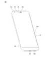
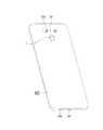
- FIGS. 2 and 3are perspective views viewed from the front and rear of the mobile terminal according to the present invention.
- FIG. 4is a cross-sectional view of a side surface of a mobile terminal.
- FIG. 5is a perspective view illustrating an example of a user input unit of a mobile terminal.
- FIG. 6is a perspective view illustrating an example of a force sensor of a user input unit.
- FIG. 7 and 8are perspective views illustrating another example of the force sensor of the user input unit.
- 9 and 10are diagrams illustrating another embodiment of the force sensor of the user input unit.
- 11 and 12are diagrams showing an embodiment of the ultrasonic sensor of the user input unit and graphs showing the performance thereof.
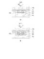
- FIG. 13is a diagram illustrating another embodiment of a user input unit.
- FIG. 1is a block diagram illustrating a mobile terminal related to the present invention.
- the mobile terminal 100includes a wireless communication unit 110 , an input unit 120 , a sensing unit 140 , an output unit 150 , an interface unit 160 , a memory 170 , a control unit 180 , and a power supply unit 190 . ) and the like.
- the components shown in FIG. 1are not essential for implementing the mobile terminal, so the mobile terminal described in this specification may have more or fewer components than those listed above.
- the wireless communication unit 110is between the mobile terminal 100 and the wireless communication system, between the mobile terminal 100 and another mobile terminal 100, or between the mobile terminal 100 and an external server. It may include one or more modules that enable wireless communication between them. In addition, the wireless communication unit 110 may include one or more modules for connecting the mobile terminal 100 to one or more networks.
- the wireless communication unit 110may include at least one of a broadcast reception module 111 , a mobile communication module 112 , a wireless Internet module 113 , a short-range communication module 114 , and a location information module 115 . .
- the broadcast reception module 111 of the wireless communication unit 110receives a broadcast signal and/or broadcast-related information from an external broadcast management server through a broadcast channel.
- the broadcast channelmay include a satellite channel and a terrestrial channel. Two or more of the broadcast reception modules may be provided to the mobile terminal 100 for simultaneous broadcast reception or broadcast channel switching for at least two broadcast channels.
- Mobile communication module 112the technical standards or communication methods for mobile communication (eg, Global System for Mobile communication (GSM), Code Division Multi Access (CDMA), Code Division Multi Access 2000 (CDMA2000), EV -DO (Enhanced Voice-Data Optimized or Enhanced Voice-Data Only), WCDMA (Wideband CDMA), HSDPA (High Speed Downlink Packet Access), HSUPA (High Speed Uplink Packet Access), LTE (Long Term Evolution), LTE-A (Long Term Evolution-Advanced, etc.) transmits and receives a radio signal to and from at least one of a base station, an external terminal, and a server on a mobile communication network constructed according to.
- GSMGlobal System for Mobile communication
- CDMACode Division Multi Access
- CDMA2000Code Division Multi Access 2000
- EV -DOEnhanced Voice-Data Optimized or Enhanced Voice-Data Only
- WCDMAWideband CDMA
- HSDPAHigh Speed Downlink Packet Access
- HSUPAHigh Speed Uplink Packet Access
- the wireless signalmay include various types of data according to transmission/reception of a voice call signal, a video call signal, or a text/multimedia message.
- the wireless Internet module 113refers to a module for wireless Internet access, and may be built-in or external to the mobile terminal 100 .
- the wireless Internet module 113is configured to transmit and receive wireless signals in a communication network according to wireless Internet technologies.
- wireless Internet technologyfor example, WLAN (Wireless LAN), Wi-Fi (Wireless-Fidelity), Wi-Fi (Wireless Fidelity) Direct, DLNA (Digital Living Network Alliance), WiBro (Wireless Broadband), WiMAX (World Interoperability for Microwave Access), High Speed Downlink Packet Access (HSDPA), High Speed Uplink Packet Access (HSUPA), Long Term Evolution (LTE), Long Term Evolution-Advanced (LTE-A), etc.
- the wireless Internet module ( 113)transmits and receives data according to at least one wireless Internet technology within a range including Internet technologies not listed above.
- the wireless Internet module 113 for performing wireless Internet access through the mobile communication networkmay be understood as a type of the mobile communication module 112 .
- Short-range communication module 114is for short-range communication, BluetoothTM, RFID (Radio Frequency Identification), infrared communication (Infrared Data Association; IrDA), UWB (Ultra Wideband), ZigBee, NFC At least one of (Near Field Communication), Wireless-Fidelity (Wi-Fi), Wi-Fi Direct, and Wireless Universal Serial Bus (USB) technologies may be used to support short-range communication.
- the short-distance communication module 114is, between the mobile terminal 100 and the wireless communication system, between the mobile terminal 100 and another mobile terminal 100, or the mobile terminal 100 through wireless area networks (Wireless Area Networks). ) and another mobile terminal (100, or an external server) can support wireless communication between the network located.
- the local area networkmay be local area networks (Wireless Personal Area Networks).
- the location information module 115is a module for obtaining a location (or current location) of a mobile terminal, and a representative example thereof includes a Global Positioning System (GPS) module or a Wireless Fidelity (WiFi) module.
- GPSGlobal Positioning System
- Wi-FiWireless Fidelity
- the mobile terminalutilizes a GPS module, it can acquire the location of the mobile terminal by using a signal transmitted from a GPS satellite.
- the location of the mobile terminalmay be obtained based on information of the Wi-Fi module and a wireless access point (AP) that transmits or receives a wireless signal.
- APwireless access point
- the location information module 115may perform any function of the other modules of the wireless communication unit 110 to obtain data on the location of the mobile terminal as a substitute or additionally.
- the location information module 115is a module used to obtain the location (or current location) of the mobile terminal, and is not limited to a module that directly calculates or obtains the location of the mobile terminal.
- the input unit 120includes a camera 121 or an image input unit for inputting an image signal, a microphone 122 or an audio input unit for inputting an audio signal, and a user input unit 123 for receiving information from a user, for example, , a touch key, a push key, etc.).
- the voice data or image data collected by the input unit 120may be analyzed and processed as a user's control command.
- the camera 121processes an image frame such as a still image or a moving image obtained by an image sensor in a video call mode or a shooting mode.
- the processed image framemay be displayed on the display unit 151 or stored in the memory 170 .
- the plurality of cameras 121 provided in the mobile terminal 100may be arranged to form a matrix structure, and through the cameras 121 forming the matrix structure as described above, various angles or focal points are applied to the mobile terminal 100 .
- a plurality of image information withcan be input.
- the plurality of cameras 121may be arranged in a stereo structure to acquire a left image and a right image for realizing a stereoscopic image.
- the microphone 122processes an external sound signal as electrical voice data.
- the processed voice datamay be utilized in various ways according to a function (or an application program being executed) being performed by the mobile terminal 100 .
- various noise removal algorithms for removing noise generated in the process of receiving an external sound signalmay be implemented in the microphone 122 .
- the user input unit 123is for receiving information from the user, and when information is input through the user input unit 123 , the controller 180 may control the operation of the mobile terminal 100 to correspond to the input information.
- the user input unit 123is a mechanical input means (or a mechanical key, for example, a button located on the front, rear or side of the mobile terminal 100, a dome switch, a jog wheel, jog switch, etc.) and a touch input means.
- the touch input meansconsists of a virtual key, a soft key, or a visual key displayed on the touch screen through software processing, or a part other than the touch screen. It may be made of a touch key (touch key) disposed on the.
- the virtual key or the visual keyit is possible to be displayed on the touch screen while having various forms, for example, graphic (graphic), text (text), icon (icon), video (video) or these can be made by a combination of
- the sensing unit 140may include one or more sensors for sensing at least one of information in the mobile terminal, surrounding environment information surrounding the mobile terminal, and user information.
- the sensing unit 140may include a proximity sensor 141, an illumination sensor 142, an illumination sensor, a touch sensor, an acceleration sensor, a magnetic sensor, and gravity.
- G-sensorgyroscope sensor
- motion sensorRGB sensor
- infrared sensorIR sensor: infrared sensor
- fingerprint recognition sensorfingerprint recognition sensor
- ultrasonic sensorultrasonic sensor
- optical sensorseg, cameras (see 121)
- microphonessee 122
- battery gaugesenvironmental sensors (eg, barometers, hygrometers, thermometers, radiation detection sensors, It may include at least one of a thermal sensor, a gas sensor, etc.) and a chemical sensor (eg, an electronic nose, a healthcare sensor, a biometric sensor, etc.).
- the mobile terminal disclosed in the present specificationmay combine and utilize information sensed by at least two or more of these sensors.
- the output unit 150is for generating an output related to visual, auditory or tactile sense, and includes at least one of a display unit 151 , a sound output unit 152 , a haptip module 153 , and an optical output unit 154 . can do.
- the display unit 151may implement a touch screen by forming a layer structure with the touch sensor or being integrally formed. Such a touch screen may function as the user input unit 123 providing an input interface between the mobile terminal 100 and the user, and may provide an output interface between the mobile terminal 100 and the user.
- the sound output unit 152may output audio data received from the wireless communication unit 110 or stored in the memory 170 in a call signal reception, a call mode or a recording mode, a voice recognition mode, a broadcast reception mode, and the like.
- the sound output unit 152also outputs a sound signal related to a function (eg, a call signal reception sound, a message reception sound, etc.) performed in the mobile terminal 100 .
- the sound output unit 152may include a receiver, a speaker, a buzzer, and the like.
- the haptic module 153generates various tactile effects that the user can feel.
- a representative example of the tactile effect generated by the haptic module 153may be vibration.
- the intensity and pattern of vibration generated by the haptic module 153may be controlled by a user's selection or setting of the controller. For example, the haptic module 153 may synthesize and output different vibrations or output them sequentially.
- the light output unit 154outputs a signal for notifying the occurrence of an event by using the light of the light source of the mobile terminal 100 .
- Examples of the event occurring in the mobile terminal 100may be message reception, call signal reception, missed call, alarm, schedule notification, email reception, information reception through an application, and the like.
- the interface unit 160serves as a passage with various types of external devices connected to the mobile terminal 100 .
- the interface unit 160connects a device equipped with a wired/wireless headset port, an external charger port, a wired/wireless data port, a memory card port, and an identification module. It may include at least one of a port, an audio input/output (I/O) port, a video input/output (I/O) port, and an earphone port.
- the mobile terminal 100may perform appropriate control related to the connected external device.
- the memory 170stores data supporting various functions of the mobile terminal 100 .
- the memory 170may store a plurality of application programs (or applications) driven in the mobile terminal 100 , data for operation of the mobile terminal 100 , and commands. At least some of these application programs may be downloaded from an external server through wireless communication. In addition, at least some of these application programs may exist on the mobile terminal 100 from the time of shipment for basic functions (eg, incoming calls, outgoing functions, message reception, and outgoing functions) of the mobile terminal 100 . Meanwhile, the application program may be stored in the memory 170 , installed on the mobile terminal 100 , and driven to perform an operation (or function) of the mobile terminal by the controller 180 .
- the controller 180In addition to the operation related to the application program, the controller 180 generally controls the overall operation of the mobile terminal 100 .
- the controller 180may provide or process appropriate information or functions to the user by processing signals, data, information, etc. input or output through the above-described components or by driving an application program stored in the memory 170 .
- controller 180may control at least some of the components discussed with reference to FIG. 1 in order to drive an application program stored in the memory 170 . Furthermore, in order to drive the application program, the controller 180 may operate at least two or more of the components included in the mobile terminal 100 in combination with each other.
- the power supply unit 190receives external power and internal power under the control of the control unit 180 to supply power to each component included in the mobile terminal 100 .
- the power supply unit 190includes a battery, and the battery may be a built-in battery or a replaceable battery.
- At least some of the respective componentsmay operate in cooperation with each other to implement the operation, control, or control method of the mobile terminal according to various embodiments described below. Also, the operation, control, or control method of the mobile terminal may be implemented on the mobile terminal by driving at least one application program stored in the memory 170 .
- the broadcast reception module 111 of the wireless communication unit 110receives a broadcast signal and/or broadcast-related information from an external broadcast management server through a broadcast channel.
- the broadcast channelmay include a satellite channel and a terrestrial channel. Two or more of the broadcast reception modules may be provided to the mobile terminal 100 for simultaneous broadcast reception or broadcast channel switching for at least two broadcast channels.
- Mobile communication module 112the technical standards or communication methods for mobile communication (eg, Global System for Mobile communication (GSM), Code Division Multi Access (CDMA), Code Division Multi Access 2000 (CDMA2000), EV -DO (Enhanced Voice-Data Optimized or Enhanced Voice-Data Only), WCDMA (Wideband CDMA), HSDPA (High Speed Downlink Packet Access), HSUPA (High Speed Uplink Packet Access), LTE (Long Term Evolution), LTE-A (Long Term Evolution-Advanced, etc.) transmits and receives a radio signal to and from at least one of a base station, an external terminal, and a server on a mobile communication network constructed according to.
- GSMGlobal System for Mobile communication
- CDMACode Division Multi Access
- CDMA2000Code Division Multi Access 2000
- EV -DOEnhanced Voice-Data Optimized or Enhanced Voice-Data Only
- WCDMAWideband CDMA
- HSDPAHigh Speed Downlink Packet Access
- HSUPAHigh Speed Uplink Packet Access
- the wireless signalmay include various types of data according to transmission/reception of a voice call signal, a video call signal, or a text/multimedia message.
- the wireless Internet module 113refers to a module for wireless Internet access, and may be built-in or external to the mobile terminal 100 .
- the wireless Internet module 113is configured to transmit and receive wireless signals in a communication network according to wireless Internet technologies.
- wireless Internet technologyfor example, WLAN (Wireless LAN), Wi-Fi (Wireless-Fidelity), Wi-Fi (Wireless Fidelity) Direct, DLNA (Digital Living Network Alliance), WiBro (Wireless Broadband), WiMAX (World Interoperability for Microwave Access), High Speed Downlink Packet Access (HSDPA), High Speed Uplink Packet Access (HSUPA), Long Term Evolution (LTE), Long Term Evolution-Advanced (LTE-A), etc.
- the wireless Internet module ( 113)transmits and receives data according to at least one wireless Internet technology within a range including Internet technologies not listed above.
- the wireless Internet module 113 for performing wireless Internet access through the mobile communication networkmay be understood as a type of the mobile communication module 112 .
- Short-range communication module 114is for short-range communication, BluetoothTM, RFID (Radio Frequency Identification), infrared communication (Infrared Data Association; IrDA), UWB (Ultra Wideband), ZigBee, NFC At least one of (Near Field Communication), Wireless-Fidelity (Wi-Fi), Wi-Fi Direct, and Wireless Universal Serial Bus (USB) technologies may be used to support short-range communication.
- the short-distance communication module 114is, between the mobile terminal 100 and the wireless communication system, between the mobile terminal 100 and another mobile terminal 100, or the mobile terminal 100 through wireless area networks (Wireless Area Networks). ) and another mobile terminal (100, or an external server) can support wireless communication between the network located.
- the local area networkmay be local area networks (Wireless Personal Area Networks).
- the other mobile terminal 100is a wearable device capable of exchanging (or interworking) data with the mobile terminal 100 according to the present invention, for example, a smart watch, smart glasses. (smart glass) or HMD (head mounted display)).
- the short-range communication module 114may detect (or recognize) a wearable device capable of communicating with the mobile terminal 100 in the vicinity of the mobile terminal 100 .
- the controller 180transmits at least a portion of data processed by the mobile terminal 100 to the short-range communication module ( 114) to transmit to the wearable device. Accordingly, the user of the wearable device may use data processed by the mobile terminal 100 through the wearable device.
- the userwhen a call is received in the mobile terminal 100, the user performs a phone call through the wearable device, or when a message is received in the mobile terminal 100, the user receives the received call through the wearable device. It is possible to check the message.
- the location information module 115is a module for obtaining a location (or current location) of a mobile terminal, and a representative example thereof includes a Global Positioning System (GPS) module or a Wireless Fidelity (WiFi) module.
- GPSGlobal Positioning System
- Wi-FiWireless Fidelity
- the mobile terminalutilizes a GPS module, it can acquire the location of the mobile terminal by using a signal transmitted from a GPS satellite.
- the location of the mobile terminalmay be obtained based on information of the Wi-Fi module and a wireless access point (AP) that transmits or receives a wireless signal.
- APwireless access point
- the location information module 115may perform any function of the other modules of the wireless communication unit 110 to obtain data on the location of the mobile terminal as a substitute or additionally.
- the location information module 115is a module used to obtain the location (or current location) of the mobile terminal, and is not limited to a module that directly calculates or obtains the location of the mobile terminal.
- the input unit 120is for input of image information (or signal), audio information (or signal), data, or information input from a user.
- the mobile terminal 100has one Alternatively, a plurality of cameras 121 may be provided.
- the camera 121processes an image frame such as a still image or a moving image obtained by an image sensor in a video call mode or a shooting mode.
- the processed image framemay be displayed on the display unit 151 or stored in the memory 170 .
- the plurality of cameras 121 provided in the mobile terminal 100may be arranged to form a matrix structure, and through the cameras 121 forming the matrix structure as described above, various angles or focal points are applied to the mobile terminal 100 .
- a plurality of image information having a plurality of imagesmay be input.
- the plurality of cameras 121may be arranged in a stereo structure to acquire a left image and a right image for realizing a stereoscopic image.
- the microphone 122processes an external sound signal as electrical voice data.
- the processed voice datamay be utilized in various ways according to a function (or an application program being executed) being performed by the mobile terminal 100 .
- various noise removal algorithms for removing noise generated in the process of receiving an external sound signalmay be implemented in the microphone 122 .
- the user input unit 123is for receiving information from the user, and when information is input through the user input unit 123 , the controller 180 may control the operation of the mobile terminal 100 to correspond to the input information.
- the user input unit 123is a mechanical input means (or a mechanical key, for example, a button located on the front, rear or side of the mobile terminal 100, a dome switch, a jog wheel, jog switch, etc.) and a touch input means.
- the touch input meansconsists of a virtual key, a soft key, or a visual key displayed on the touch screen through software processing, or a part other than the touch screen. It may be made of a touch key (touch key) disposed on the.
- the virtual key or the visual keyit is possible to be displayed on the touch screen while having various forms, for example, graphic (graphic), text (text), icon (icon), video (video) or these can be made by a combination of
- the sensing unit 140senses at least one of information in the mobile terminal, surrounding environment information surrounding the mobile terminal, and user information, and generates a sensing signal corresponding thereto.
- the controller 180may control the driving or operation of the mobile terminal 100 or perform data processing, function, or operation related to an application program installed in the mobile terminal 100 based on the sensing signal. Representative sensors among various sensors that may be included in the sensing unit 140 will be described in more detail.
- the proximity sensor 141refers to a sensor that detects the presence or absence of an object approaching a predetermined detection surface or an object existing in the vicinity without mechanical contact using the force of an electromagnetic field or infrared rays.
- the proximity sensor 141may be disposed in an inner region of the mobile terminal covered by the touch screen described above or near the touch screen.
- the proximity sensor 141examples include a transmission type photoelectric sensor, a direct reflection type photoelectric sensor, a mirror reflection type photoelectric sensor, a high frequency oscillation type proximity sensor, a capacitive type proximity sensor, a magnetic type proximity sensor, and an infrared proximity sensor.
- the proximity sensor 141may be configured to detect the proximity of an object having conductivity by a change in an electric field according to the proximity of the object. In this case, the touch screen (or touch sensor) itself may be classified as a proximity sensor.
- the act of approaching an object on the touch screen without contacting it so that the object is recognized that it is located on the touch screenis called “proximity touch”, and the touch The act of actually touching an object on the screen is called “contact touch”.
- the position where the object is touched in proximity on the touch screenmeans a position where the object is perpendicular to the touch screen when the object is touched in proximity.
- the proximity sensor 141may detect a proximity touch and a proximity touch pattern (eg, proximity touch distance, proximity touch direction, proximity touch speed, proximity touch time, proximity touch position, proximity touch movement state, etc.) have.
- the controller 180processes data (or information) corresponding to the proximity touch operation and the proximity touch pattern sensed through the proximity sensor 141 as described above, and further, provides visual information corresponding to the processed data. It can be printed on the touch screen. Furthermore, the controller 180 may control the mobile terminal 100 to process different operations or data (or information) according to whether a touch to the same point on the touch screen is a proximity touch or a contact touch. .
- the touch sensorreceives a touch (or touch input) applied to the touch screen (or the display unit 151) using at least one of various touch methods such as a resistive film method, a capacitive method, an infrared method, an ultrasonic method, and a magnetic field method. detect a touch (or touch input) applied to the touch screen (or the display unit 151) using at least one of various touch methods such as a resistive film method, a capacitive method, an infrared method, an ultrasonic method, and a magnetic field method. detect
- the touch sensormay be configured to convert a change in pressure applied to a specific part of the touch screen or a change in capacitance occurring in a specific part of the touch screen into an electrical input signal.
- the touch sensormay be configured to detect a position, an area, a pressure at the time of touch, an electrostatic capacitance at the time of touch, etc. in which a touch object applying a touch on the touch screen is touched on the touch sensor.
- the touch objectis an object that applies a touch to the touch sensor, and may be, for example, a finger, a touch pen, a stylus pen, or a pointer.
- the touch controllerprocesses the signal(s) and then transmits corresponding data to the controller 180 . Accordingly, the controller 180 can know which area of the display unit 151 has been touched, and the like.
- the touch controllermay be a component separate from the controller 180 , or may be the controller 180 itself.
- the controller 180may perform different controls or may perform the same control according to the type of the touch object that touches the touch screen (or a touch key provided in addition to the touch screen). Whether to perform different control or the same control according to the type of the touch object may be determined according to the current operating state of the mobile terminal 100 or a running application program.
- the above-described touch sensor and proximity sensorindependently or in combination, a short (or tap) touch on the touch screen (short touch), long touch (long touch), multi touch (multi touch), drag touch (drag touch) ), flick touch, pinch-in touch, pinch-out touch, swype touch, hovering touch, etc. It can sense touch.
- the ultrasonic sensormay recognize position information of a sensing target by using ultrasonic waves.
- the controller 180may calculate the position of the wave source through information sensed by the optical sensor and the plurality of ultrasonic sensors.
- the position of the wave sourcemay be calculated using the property that light is much faster than ultrasonic waves, that is, the time at which light arrives at the optical sensor is much faster than the time at which ultrasonic waves reach the ultrasonic sensor. More specifically, the position of the wave source may be calculated using a time difference from the time that the ultrasonic wave arrives using light as a reference signal.
- the camera 121 as seen in the configuration of the input unit 120includes at least one of a camera sensor (eg, CCD, CMOS, etc.), a photo sensor (or image sensor), and a laser sensor.
- a camera sensoreg, CCD, CMOS, etc.
- a photo sensoror image sensor
- a laser sensore.g., a laser sensor
- the camera 121 and the laser sensormay be combined with each other to detect a touch of a sensing target for a 3D stereoscopic image.
- the photo sensormay be stacked on the display device, and the photo sensor is configured to scan the motion of the sensing target close to the touch screen. More specifically, the photo sensor mounts photo diodes and transistors (TRs) in rows/columns and scans the contents placed on the photo sensor using electrical signals that change according to the amount of light applied to the photo diode. That is, the photo sensor calculates the coordinates of the sensing target according to the amount of change in light, and through this, location information of the sensing target can be obtained.
- TRsphoto diodes and transistors
- the display unit 151displays (outputs) information processed by the mobile terminal 100 .
- the display unit 151may display execution screen information of an application program driven in the mobile terminal 100 or UI (User Interface) and GUI (Graphic User Interface) information according to the execution screen information. .
- the display unit 151may be configured as a stereoscopic display unit for displaying a stereoscopic image.
- a three-dimensional display methodsuch as a stereoscopic method (glasses method), an auto stereoscopic method (glassesless method), or a projection method (holographic method) may be applied to the stereoscopic display unit.
- the sound output unit 152may output audio data received from the wireless communication unit 110 or stored in the memory 170 in a call signal reception, a call mode or a recording mode, a voice recognition mode, a broadcast reception mode, and the like.
- the sound output unit 152also outputs a sound signal related to a function (eg, a call signal reception sound, a message reception sound, etc.) performed in the mobile terminal 100 .
- the sound output unit 152may include a receiver, a speaker, a buzzer, and the like.
- the haptic module 153generates various tactile effects that the user can feel.
- a representative example of the tactile effect generated by the haptic module 153may be vibration.
- the intensity and pattern of vibration generated by the haptic module 153may be controlled by a user's selection or setting of the controller. For example, the haptic module 153 may synthesize and output different vibrations or output them sequentially.
- the haptic module 153is configured to respond to stimuli such as a pin arrangement that moves vertically with respect to the contact skin surface, a jet force or suction force of air through a nozzle or an inlet, rubbing against the skin surface, contact of an electrode, electrostatic force, etc.
- stimulisuch as a pin arrangement that moves vertically with respect to the contact skin surface, a jet force or suction force of air through a nozzle or an inlet, rubbing against the skin surface, contact of an electrode, electrostatic force, etc.
- Various tactile effectscan be generated, such as the effect of heat absorption and the effect of reproducing a feeling of coolness and warmth using an element capable of absorbing heat or generating heat.
- the haptic module 153may not only deliver a tactile effect through direct contact, but may also be implemented so that the user can feel the tactile effect through a muscle sense such as a finger or arm. Two or more haptic modules 153 may be provided according to the configuration of the mobile terminal 100 .
- the light output unit 154outputs a signal for notifying the occurrence of an event by using the light of the light source of the mobile terminal 100 .
- Examples of the event occurring in the mobile terminal 100may be message reception, call signal reception, missed call, alarm, schedule notification, email reception, information reception through an application, and the like.
- the signal output from the optical output unit 154is implemented as the mobile terminal emits light of a single color or a plurality of colors toward the front or rear.
- the signal outputmay be terminated when the mobile terminal detects the user's event confirmation.
- the interface unit 160serves as a passage with all external devices connected to the mobile terminal 100 .
- the interface unit 160receives data from an external device, receives power and transmits it to each component inside the mobile terminal 100 , or transmits data inside the mobile terminal 100 to an external device.
- a wired/wireless headset port, an external charger port, a wired/wireless data port, a memory card port, a port for connecting a device equipped with an identification module (port), an audio I/O (Input/Output) port, a video I/O (Input/Output) port, an earphone port, etc.may be included in the interface unit 160 .
- the identification moduleis a chip storing various types of information for authenticating the use authority of the mobile terminal 100, a user identification module (UIM), a subscriber identity module (subscriber identity module; SIM), universal user authentication It may include a universal subscriber identity module (USIM) and the like.
- a device equipped with an identification module(hereinafter, 'identification device') may be manufactured in the form of a smart card. Accordingly, the identification device may be connected to the terminal 100 through the interface unit 160 .
- the interface unit 160becomes a passage through which power from the cradle is supplied to the mobile terminal 100, or is input from the cradle by a user.
- Various command signalsmay be a path through which the mobile terminal 100 is transmitted.
- Various command signals or the power input from the cradlemay be operated as signals for recognizing that the mobile terminal 100 is correctly mounted on the cradle.
- the memory 170may store a program for the operation of the controller 180 , and may temporarily store input/output data (eg, a phone book, a message, a still image, a moving picture, etc.).
- the memory 170may store data related to vibration and sound of various patterns output when a touch input on the touch screen is input.
- Memory 170is a flash memory type (flash memory type), hard disk type (hard disk type), SSD type (Solid State Disk type), SDD type (Silicon Disk Drive type), multimedia card micro type (multimedia card micro type) ), card-type memory (such as SD or XD memory), random access memory (RAM), static random access memory (SRAM), read-only memory (ROM), electrically erasable programmable read (EEPROM) -only memory), a programmable read-only memory (PROM), a magnetic memory, a magnetic disk, and an optical disk may include at least one type of storage medium.
- the mobile terminal 100may be operated in relation to a web storage that performs a storage function of the memory 170 on the Internet.
- the controller 180controls the operation related to the application program and the general operation of the mobile terminal 100 in general. For example, if the state of the mobile terminal satisfies a set condition, the controller 180 may execute or release a lock state restricting input of a user's control command to applications.
- the controller 180performs control and processing related to voice calls, data communication, video calls, etc., or performs pattern recognition processing capable of recognizing handwriting input or drawing input performed on the touch screen as characters and images, respectively.
- the controller 180may control one or a combination of any one or a plurality of the components described above.
- the power supply unit 190receives external power and internal power under the control of the control unit 180 to supply power required for operation of each component.
- the power supply unit 190includes a battery, and the battery may be a built-in battery configured to be rechargeable, and may be detachably coupled to the terminal body for charging or the like.
- the power supply unit 190may include a connection port, and the connection port may be configured as an example of the interface 160 to which an external charger that supplies power for charging the battery is electrically connected.
- the power supply unit 190may be configured to charge the battery in a wireless manner without using the connection port.
- the power supply unit 190uses one or more of an inductive coupling method based on a magnetic induction phenomenon or a resonance coupling method based on an electromagnetic resonance phenomenon from an external wireless power transmitter. power can be transmitted.
- the disclosed mobile terminal 100has a bar-shaped terminal body.
- the present inventionis not limited thereto, and may be applied to various structures such as a folder type, a flip type, a slide type, a swing type, a swivel type, a foldable type, and a rollable type in which two or more bodies are coupled to be relatively movable.
- a folder typea flip type
- a slide typea slide type
- a swing typea swivel type
- a foldable typea rollable type in which two or more bodies are coupled to be relatively movable.
- the terminal bodymay be understood as a concept referring to the mobile terminal 100 as at least one aggregate.
- the mobile terminal 100includes a case (eg, a frame, a housing, a cover, etc.) forming an exterior. Various parts are mounted inside the case, and the display unit 151 is disposed on the front side of the case to output information.
- the display unitmay be located on a part of the front surface of the body of the mobile terminal and cover the entire front surface or the display unit is located. However, as the size of the display unit has recently increased, the display unit may cover the entire front surface of the body and further extend to the side surfaces.
- the display unitmay include a front portion facing the front and a side portion facing the side, the side portion is formed only on both sides in one direction of the mobile terminal, as shown in FIG. 2 , may be located on both sides of the mobile terminal in the left and right direction.
- the front part and the side part of the display unitmay be connected to form a curved surface.
- the window 151amay cover the display unit and form the appearance of the mobile terminal.
- the window 151amay be positioned up to the side of the mobile terminal to cover the entire display unit, and may be provided in a U-shape to cover both the front and side surfaces of the display unit.
- the window 151amay include a curved surface corresponding to the continuous curved surface of the front and side portions of the display unit.
- the window 151amay be exposed to the outside to form an exterior together with the window 151a. It may further include a rear cover 105 forming a rear exterior, the rear cover 105 may include a glass material like the window (151a). The rear cover 105 also forms a curved surface to form a curved surface like the front window and may extend in the lateral direction.
- a battery, a main board, a sound output unit 152 , a camera 121 and the likemay be disposed inside the case, and the camera 121a and the proximity sensor 141 may be exposed in the front direction.
- the rear cover 105may be provided with an opening for exposing the camera (121b) or the sound output unit (152b) to the outside.
- a camera window covering the openingmay be included.
- the cases 101 and 105may be formed by injecting synthetic resin or may be formed of metal, for example, stainless steel (STS), aluminum (Al), titanium (Ti), or the like.
- STSstainless steel
- Alaluminum
- Tititanium
- the mobile terminal 100may be configured such that one case provides the internal space.
- the mobile terminal 100 of a uni-body in which synthetic resin or metal is connected from the side to the backcan be implemented.
- the mobile terminal 100may include a waterproofing unit (not shown) to prevent water from permeating into the terminal body.
- the mobile terminal 100 in which the second sound output unit 152b and the second camera 121b are disposed on the rear sidewill be described as an example.
- first operation unit 123amay not be provided on the front surface of the terminal body
- second sound output unit 152bmay be provided on the side surface of the terminal body instead of the rear surface of the terminal body.
- the display unit 151displays (outputs) information processed by the mobile terminal 100 .
- the display unit 151may display execution screen information of an application program driven in the mobile terminal 100 or UI (User Interface) and GUI (Graphic User Interface) information according to the execution screen information. .
- the display unit 151may include a liquid crystal display (LCD), a thin film transistor-liquid crystal display (TFT LCD), an organic light-emitting diode (OLED), and a flexible display (Flexible Display).
- LCDliquid crystal display
- TFT LCDthin film transistor-liquid crystal display
- OLEDorganic light-emitting diode
- Flexible DisplayFlexible Display
- displaya three-dimensional display (3D display)
- e-ink displaymay include at least one.
- two or more display units 151may exist according to an implementation form of the mobile terminal 100 .
- a plurality of display unitsmay be spaced apart on one surface or disposed integrally, or may be disposed on different surfaces, respectively.
- the display unit 151may include a touch sensor for sensing a touch on the display unit 151 so as to receive a control command input by a touch method. Using this, when a touch is made on the display unit 151 , the touch sensor detects the touch, and the controller 180 may generate a control command corresponding to the touch based thereon.
- the content input by the touch methodmay be letters or numbers, or menu items that can be instructed or designated in various modes.
- the touch sensoris configured in the form of a film having a touch pattern and disposed between the window 151a and a display (not shown) on the rear surface of the window 151a, or a metal wire patterned directly on the rear surface of the window 151a.
- the touch sensormay be formed integrally with the display.
- the touch sensormay be disposed on a substrate of the display or provided inside the display.
- the display unit 151may form a touch screen together with the touch sensor, and in this case, the touch screen may function as the user input unit 123 (refer to FIG. 1 ). In some cases, the touch screen may replace at least some functions of the first operation unit 123a.
- the first sound output unit 152amay be implemented as a receiver that transmits a call sound to the user's ear, and the second sound output unit 152b is a loudspeaker that outputs various alarm sounds or multimedia reproduction sounds. ) can be implemented in the form of
- a sound hole for emitting sound generated from the first sound output unit 152amay be formed in the window 151a of the display unit 151 .
- the present inventionis not limited thereto, and the sound may be configured to be emitted along an assembly gap between structures (eg, a gap between the window 151a and the case location).
- the appearance of the mobile terminal 100may be simplified because the hole formed independently for sound output is not visible or hidden.
- the light output unit 154is configured to output light to notify the occurrence of an event. Examples of the event include message reception, call signal reception, missed call, alarm, schedule notification, email reception, and information reception through an application.
- the controller 180may control the light output unit 154 to end the light output.
- the first camera 121aprocesses an image frame of a still image or a moving image obtained by an image sensor in a shooting mode or a video call mode.
- the processed image framemay be displayed on the display unit 151 and stored in the memory 170 .
- the first and second manipulation units 123a and 123bare an example of the user input unit 123 operated to receive a command for controlling the operation of the mobile terminal 100, and may be collectively referred to as a manipulating portion. have.
- the first and second operation units 123a and 123bmay be employed in any manner as long as they are operated in a tactile manner such as touch, push, scroll, and the like while the user receives a tactile feeling.
- the first and second manipulation units 123a and 123bmay be operated in a manner in which the user is operated without a tactile feeling through a proximity touch, a hovering touch, or the like.
- the first operation unit 123ais exemplified as a touch key, but the present invention is not limited thereto.
- the first operation unit 123amay be a push key (mechanical key) or may be configured as a combination of a touch key and a push key.
- the contents input by the first and second operation units 123a and 123bmay be variously set.
- the first operation unit 123areceives commands such as menu, home key, cancel, search, etc.
- the second operation unit 123bis output from the first or second sound output units 152a and 152b. It is possible to receive a command such as adjusting the volume of the sound and switching to the touch recognition mode of the display unit 151 .
- a rear input unit(not shown) may be provided on the rear surface of the terminal body.
- the rear input unitis manipulated to receive a command for controlling the operation of the mobile terminal 100 , and input contents may be variously set.
- a commandsuch as power on/off, start, end, scroll, etc., control of the sound output from the first and second sound output units 152a and 152b, and a touch recognition mode of the display unit 151
- the rear input unitmay be implemented in a form capable of input by a touch input, a push input, or a combination thereof.
- the rear input unitmay be disposed to overlap the display unit 151 on the front side in the thickness direction of the terminal body.
- the rear input unitmay be disposed on the upper rear portion of the terminal body so that the user can easily manipulate the terminal body using the index finger when holding the terminal body with one hand.
- the present inventionis not necessarily limited thereto, and the position of the rear input unit may be changed.
- the rear input unitwhen the rear input unit is provided on the rear surface of the terminal body, a new type of user interface using the same can be implemented.
- the aforementioned touch screen or rear input unitreplaces at least some functions of the first operation unit 123a provided on the front surface of the terminal body, the first operation unit 123a is not disposed on the front surface of the terminal body,
- the display unit 151may be configured with a larger screen.
- the mobile terminal 100may be provided with a fingerprint recognition sensor for recognizing a user's fingerprint, and the controller 180 may use fingerprint information detected through the fingerprint recognition sensor as an authentication means.
- the fingerprint recognition sensormay be built in the display unit 151 or the user input unit 123 .
- the microphone 122is configured to receive a user's voice, other sounds, and the like.
- the microphone 122may be provided at a plurality of locations and configured to receive stereo sound.
- the interface unit 160serves as a passage through which the mobile terminal 100 can be connected to an external device.
- the interface unit 160is a connection terminal for connection with another device (eg, earphone, external speaker), a port for short-distance communication (eg, infrared port (IrDA Port), Bluetooth port (Bluetooth) Port), a wireless LAN port, etc.], or at least one of a power supply terminal for supplying power to the mobile terminal 100 .
- the interface unit 160may be implemented in the form of a socket accommodating an external card such as a subscriber identification module (SIM), a user identity module (UIM), or a memory card for information storage.
- SIMsubscriber identification module
- UIMuser identity module
- memory cardfor information storage.
- a second camera 121bmay be disposed on the rear side of the terminal body.
- the second camera 121bhas a photographing direction substantially opposite to that of the first camera 121a.
- the second camera 121bmay include a plurality of lenses arranged along at least one line.
- the plurality of lensesmay be arranged in a matrix form.
- Such a cameramay be referred to as an 'array camera'.
- the second camera 121bis configured as an array camera, images may be captured in various ways using a plurality of lenses, and images of better quality may be obtained.
- the flash 124may be disposed adjacent to the second camera 121b.
- the flash 124shines light toward the subject when the subject is photographed by the second camera 121b.
- a second sound output unit 152bmay be additionally disposed on the terminal body.
- the second sound output unit 152bmay implement a stereo function together with the first sound output unit 152a, and may be used to implement a speakerphone mode during a call.
- At least one antenna for wireless communicationmay be provided in the terminal body.
- the antennamay be built into the terminal body or formed in the case.
- the antenna forming a part of the broadcast reception module 111(refer to FIG. 1 ) may be configured to be withdrawable from the terminal body.
- the antennamay be formed in a film type and attached to the inner surface of the rear cover, and a case including a conductive material may be configured to function as an antenna.
- a power supply unit 190(refer to FIG. 1 ) for supplying power to the mobile terminal 100 is provided in the terminal body.
- the power supply unit 190may include a battery built into the terminal body or detachably configured from the outside of the terminal body.
- the batterymay be configured to receive power through a power cable connected to the interface unit 160 .
- the batterymay be configured to be able to be charged wirelessly through a wireless charging device.
- the wireless chargingmay be implemented by a magnetic induction method or a resonance method (magnetic resonance method).
- An accessory for protecting the appearance of the mobile terminal 100 or supporting or extending a function of the mobile terminal 100may be added.
- the cover or pouchmay be configured to extend the function of the mobile terminal 100 by interworking with the display unit 151 .
- the case of the mobile terminal 100may include a first case 101 positioned at the front and a second case 102 positioned on the side.
- the first case 101 and the second case 102may be integrally configured, and together with the rear cover 105 that covers the rear surface provides a mounting space for electronic components.
- the display unit 151is coupled to the first case 101 and the second case 102 , and may be located on the side of the mobile terminal 100 as well as the front of the mobile terminal 100 .
- the display unit 151may include a front portion overlapping the first case and a side portion overlapping the second case.
- the front and side portions of the display unit 151form a continuous curved surface, and the display unit 151 may include a flexible display to form a curved surface.
- a flexible displayis a display manufactured on a thin and flexible substrate so that it can be bent like paper while maintaining the characteristics of a conventional flat panel display.
- a typical example of a flexible displayis an organic light emitting diode display, and it is characterized in that it can be implemented thinly because there is no backlight, and thus bending deformation is possible.
- the front portion of the display unit 151 of the present inventionforms a flat surface, but may be curved to form a curved surface for connection with the side portion.
- the first case 101 and the second case 102form a curved surface corresponding to the display unit 151 and may be formed as a single body.
- the display unit 151is located on the side of the mobile terminal 100 , there is a problem in that it overlaps with the user input unit 200 located on the side.
- the user input unit 200 located on the sideshould be omitted or disposed to overlap the display unit 151 .
- the conventional user input unit 200 using a dome buttonis difficult to implement because there is no mounting space because the side of the mobile terminal is covered by the display unit 151 .
- the force sensor 210may be used to implement the user input unit 200 that can be overlapped with the display unit 151 .
- the force sensor 210is also called a force touch and is characterized in that it operates by recognizing a pressing force. As a sensor that generates an electrical signal in response to minute mechanical changes, it can detect changes of several um to tens of um on the attached surface. Since the force sensor 210 does not need to be directly exposed to the outside, it may be positioned on the inner surface of the display unit 151 .
- a sensor seat portion 102ais formed on the surface facing the display unit 151 in the second case 102 to apply a force to the sensor seat portion 102a.
- a sensor 210may be disposed.
- the sensor seating portion 102amay be implemented in a concave retracted form on the surface facing the display portion 151 of the second case 102, and the force sensor 210 from the outer surface of the embodiment of FIG. 4(a). ), there is an advantage that the distance d2 from the outer surface of FIG. 4 (b) to the force sensor 210 is shorter than the distance d1.
- FIG. 5is a perspective view illustrating an example of the user input unit 200 including the force sensor 210 of FIG. 4 , and may include a flexible substrate to transmit a change detected by the force sensor 210 to the control unit.
- a plurality of force sensors 210may be disposed on one flexible substrate to receive a plurality of user inputs.
- a pairmay be arranged side by side as shown in FIG. 5 for volume control.
- the portion in which the force sensor 210 is locatedis located between the second case 102 and the display unit 151 , and the flexible substrate 217 penetrates or bypasses the second case 102 to enter the mobile terminal 100 .
- a connection part 219 that extends and is connected to the controller 180may be disposed at an end of the flexible substrate 217 .
- a circuit configuration 218 for processing the signal of the force sensor 210may also be included.
- FIG. 6is a view showing an example of the force sensor 210.
- FIG. 6 (a)is a plan view of the force sensor 210
- FIGS. 6 (b) and (c)are the sensor seating unit 102a. It is a cross-sectional view showing the seated state.
- the force sensor 210 of this embodimentis a force sensor 210 implemented using the induced current principle.
- an eddy currentis generated and a current flows in the sensing coil 211, and the pressure can be sensed through the change in the current.
- the force sensor 210includes a base substrate and a sensing coil 211 , is attached to the sensor mounting unit 102a and is disposed to form a predetermined gap 201 with the display unit 151 .
- the force sensor 210 including the sensing coil 211may recognize a user input using the principle that an induced electromotive force is generated in the coil when the distance between the metal material and the sensing coil 211 changes.
- the display unit 151may include a display panel on which information is output and a metal plate 151b on a rear surface thereof.
- the display panelcan use an organic light emitting diode display, and since it does not require a backlight, it can be implemented in a form that can be bent and deformed in the form of a thin film.
- a thin metal plate 151bmay be coupled to the rear surface of the display panel, and the metal plate 151b may be bent and deformed like the display panel.
- a gap 201is formed between the sensing coil 211 of the force sensor 210 and the metal plate 151b positioned on the rear surface of the display unit 151 , when the user presses the side surface of the display unit 151 , the gap The size of 201 is changed and a current flows in the sensing coil 211 .
- the magnitude of the pressuremay be sensed based on the strength of the current flowing through the sensing coil 211 , and may be sensed with a different input according to the magnitude of the force.
- An elastic member ( 202)may be interposed.
- the elastic member 202is physically located between the metal plate 151b and the sensing coil 211, but needs to be electrically separated, and thus includes a non-conductive material.
- the sensitivity of the force sensor 210may be adjusted according to the elasticity of the elastic member 202 . That is, the softer the elastic member 202 is, the easier the size change of the gap 201 is, the greater the sensitivity, and the harder the elastic member 202, the lower the sensitivity.
- 7 and 8are diagrams illustrating another embodiment of the force sensor 210 of the user input unit 200 .
- This embodimentis a force sensor 210 including a strain gauge 212 (strain gauge). It includes elements 2151 , 2152 , 2153 , and 2154 including a metal material, and the elements 2151 , 2152 , 2153 , and 2154 are stretched or contracted when subjected to a force, and their cross-sectional area is changed. Since the resistance value changes when the length and cross-sectional size of the device change, when the user presses the force sensor 210, the shape of the device changes and the user input can be recognized through the change in the resistance of the device.
- the strain measuring instrument 212includes a plurality of elements 2151 , 2152 , 2153 , and 2154 seated on a flexible substrate 183 , and as shown in FIG. 12 ( b ), the flexible substrate 183 .
- the force received by each element 2151 , 2152 , 2153 , and 2154is different, so that the resistance value of each element 2151 , 2152 , 2153 , 2154 may be different.
- a circuit as shown in (c) of FIG. 7may be configured to detect deformation based on the Vpos value and the Vneg value.
- the resistances (R1 to R4) of each element 2151, 2152, 2153, and 2154are equal in size to Vpos
- Vnegis the same, as shown in (b) of FIG.
- the user input module 210 of the present inventiondetects a case of bending in the opposite direction to that of FIG. 7(b). There is no need, and only one or two elements can sense the deformation in order to sense only the pressure.
- the force sensor 210 of this embodimentmay be located on the rear surface of the display unit 151 as shown in FIG.
- the strain gauge 212 positioned on the rear surface of the display unit 151may detect a change in the resistance value of the element when the user presses the display unit 151 .
- a gap 201is formed between the second case 102 and the force sensor 210 so that the display unit 151 and the deformation measuring instrument 212 can be deformed when the user presses the gap 201 .
- an elastic member 202 positioned in the gap 201may be further included to prevent a malfunction of the user input unit 200 .
- the elastic member 202is physically located between the metal plate 151b and the sensing coil 211, but needs to be electrically separated, and thus includes a non-conductive material.
- the sensitivity of the force sensor 210may be adjusted according to the elasticity of the elastic member 202 . That is, the softer the elastic member 202 is, the easier the size change of the gap 201 is, the greater the sensitivity, and the harder the elastic member 202, the lower the sensitivity. It is a diagram showing another embodiment.
- the force sensor 213 of this embodimentmay be located in the first case 101 facing the front or the third case 103 facing the rear, rather than the second case 102 .
- the force sensor 213 positioned in the second case 102 and the third case 103may use a strain gauge.
- a plurality of elements 2132 including a conductive materialare disposed on the plane of the base substrate 2131 by using a strain gauge, or as shown in FIG. 10 (b).
- a conductive strip extending in a specific directionmay use the element 2133 having a serpentine shape.
- a deformation measuring instrument for detecting deformation in the extending direction of the conductive stripmay be used.
- the second case 102, the first case 101, and the third case 103may be integrally configured, and when the user presses the second case 102, the first case 101 and the third case ( A force may be transmitted to the force sensor 213 attached to the 103 .
- the sensitivity of the user input unit 200 of the embodiment in which the force sensor 213 is coupled to the third case 103may be higher.
- the force sensor 213may detect a deformation when the mobile terminal 100 is twisted or an impact is applied, the force sensor 213 cannot distinguish the deformation caused by the user's pressure from the deformation caused by the impact. In order to remove the noise, the force sensor 213 that detects deformation in a plurality of directions may be used to distinguish a force applied in the lateral direction from other forces. In particular, in the case of the strain measuring instrument 212, since it is easy to detect deformation in various directions, it is possible to prevent erroneous input due to unintentional deformation by using a plurality of elements having different arrangement and shape of each element.
- the ultrasonic sensor 214includes a transmitter that transmits ultrasonic waves and a receiver that senses reflected and returned ultrasonic waves, and may detect a user input through the intensity and wavelength of ultrasonic waves detected by the receiver.
- the ultrasonic sensor 214 mounted on the second case 102penetrates the second case 102 and passes through the layered structure of the display unit 151 to the outside of the window. can detect a touched input.
- the ultrasonic changeis insignificant.
- the ultrasonic signal transmitted while passing through the plurality of layered structuresis lost, so the size of the ultrasonic wave that the receiver can detect is small and there is no significant change even if the user presses it.
- a user inputmay be sensed using the exposed portion 102c exposed to the outside of the second case 102 . Since the exposed portion 102c is differentiated from the window or the rear cover 105 by touch, the user can recognize the exact position without holding it. In addition, since the ultrasonic wave passes through a single medium, the wavelength of the ultrasonic wave is not lost or distorted, so as shown in FIG. can do.
- the second case 102may include the sensor seating portion 102b forming an inclined surface parallel to the exposed portion inside the exposed portion.
- FIG. 13is a diagram illustrating another embodiment of the user input unit 200 .
- This embodimentrelates to a user input unit 200 that recognizes a user input using a plurality of sensors.
- the user input unit 200 of the present embodimentmay include an ultrasonic sensor 214 as well as a force sensor 213 .
- a user inputmay be sensed using the ultrasonic sensor 214 and the deformation measuring instrument 212 including a plurality of elements positioned around the ultrasonic sensor 214 .
- the strain measuring instrument 212 and the ultrasonic sensor 214 of this embodiment integrated user input unit 200may be mounted on the second case 102, as shown in FIG. 4 (a), inside the second case 102. It may be located or may be disposed between the second case 102 and the display unit 151 .
- the force sensor 213may detect deformation regardless of the user's intention.
- the value recognized by the force sensor 213can be detected as a valid user input.
- a touch sensormay be used instead of the ultrasonic sensor 214 .
- the display unit 151may include a touch sensor or the touch sensor may be disposed to overlap the display unit 151 . Only when the touch sensor detects a touch input on the side of the display unit 151 , the deformation value of the force sensor 213 is determined as a valid value to recognize the user input.
- the display unit of the present inventioncan extend to the lateral direction, it is possible to provide a wider screen.
- the user input unitcan be arranged on the side, so that the performance of the mobile terminal can be maintained and a large screen can be implemented.
Landscapes
- Engineering & Computer Science (AREA)
- Physics & Mathematics (AREA)
- General Engineering & Computer Science (AREA)
- Theoretical Computer Science (AREA)
- Human Computer Interaction (AREA)
- General Physics & Mathematics (AREA)
- Acoustics & Sound (AREA)
- Signal Processing (AREA)
- Electromagnetism (AREA)
- Telephone Function (AREA)
Abstract
Description
Translated fromKorean본 발명은 측면까지 연장된 디스플레이부를 포함하는 이동 단말기에서 감도가 우수한 측면 사용자 입력부를 구비한 이동 단말기에 관한 것이다.The present invention relates to a mobile terminal having a side user input unit having excellent sensitivity in a mobile terminal including a display unit extending to the side.
단말기는 이동 가능여부에 따라 이동 단말기(mobile/portable terminal) 및 고정 단말기(stationary terminal)으로 나뉠 수 있다. 다시 이동 단말기는 사용자의 직접 휴대 가능 여부에 따라 휴대(형) 단말기(handheld terminal) 및 거치형 단말기(vehicle mounted terminal)로 나뉠 수 있다.The terminal may be divided into a mobile/portable terminal and a stationary terminal according to whether the terminal can be moved. Again, the mobile terminal can be divided into a handheld terminal and a vehicle mounted terminal according to whether the user can carry it directly.
이동 단말기의 기능은 다양화 되고 있다. 예를 들면, 데이터와 음성통신, 카메라를 통한 사진촬영 및 비디오 촬영, 음성녹음, 스피커 시스템을 통한 음악파일 재생 그리고 디스플레이부에 이미지나 비디오를 출력하는 기능이 있다. 일부 단말기는 전자게임 플레이 기능이 추가되거나, 멀티미디어 플레이어 기능을 수행한다. 특히 최근의 이동 단말기는 방송과 비디오나 텔레비전 프로그램과 같은 시각적 컨텐츠를 제공하는 멀티캐스트 신호를 수신할 수 있다.The functions of mobile terminals are diversifying. For example, there are functions for data and voice communication, photo and video shooting through a camera, voice recording, music file playback through a speaker system, and output of images or videos to the display unit. Some terminals add an electronic game play function or perform a multimedia player function. In particular, recent mobile terminals can receive multicast signals that provide visual content such as broadcast and video or television programs.
이와 같은 단말기(terminal)는 기능이 다양화됨에 따라 예를 들어, 사진이나 동영상의 촬영, 음악이나 동영상 파일의 재생, 게임, 방송의 수신 등의 복합적인 기능들을 갖춘 멀티미디어 기기(Multimedia player) 형태로 구현되고 있다.As such terminals are diversified in functions, for example, in the form of a multimedia device (Multimedia player) equipped with complex functions such as taking pictures or videos, playing music or video files, playing games, and receiving broadcasts. is being implemented.
이동 단말기의 멀티미디어 기능이 강화됨에 따라 디스플레이부가 차지하는 면적이 점점 넓어지고 있다. 최근에 휨변형이 가능한 플렉서블 디스플레이부를 이동 단말기에 장착할 수 있게 되면서 이동 단말기의 전면뿐만 아니라 측면까지 디스플레이부가 연장될 수 있다. 측면까지 디스플레이부가 연장 시 곡면을 이루며 연장되면 실제 연장된 길이 보다 시각적으로 더 넓은 디스플레이부를 구현할 수 있다.As the multimedia function of the mobile terminal is strengthened, the area occupied by the display unit is gradually increasing. Recently, as a flexible display unit capable of bending and deformation can be mounted on a mobile terminal, the display unit can be extended not only on the front side but also on the side surface of the mobile terminal. When the display unit extends to the side to form a curved surface, it is possible to implement a display unit that is visually wider than the actual extended length.
다만, 측방향에 위치하는 사용자 입력부와 측방향으로 연장된 디스플레이부가 중첩되는 문제가 발생하여 사용자 입력부의 구현이 어려운 문제가 있다.However, there is a problem in that the user input unit located in the lateral direction overlaps with the display unit extending in the lateral direction, so that it is difficult to implement the user input unit.
본 발명은 측방향까지 연장된 디스플레이부와 중첩하여 배치할 수 있는 사용자 입력부를 포함하는 이동 단말기를 제공하는 것을 목적으로 한다.An object of the present invention is to provide a mobile terminal including a user input unit that can be disposed to overlap with a display unit extending to the side.
케이스; 상기 케이스의 전면에 위치하는 전면부와 상기 전면부에서 연장되어 상기 케이스의 측면에 위치하는 측면부를 포함하는 디스플레이부; 상기 디스플레이부를 커버하는 윈도우; 및 상기 케이스의 측면에 위치하며 상기 디스플레이부와 중첩배치되는 사용자 입력부를 포함하는 것을 특징으로 하는 이동 단말기를 제공한다.case; a display unit including a front part positioned on the front side of the case and a side part extending from the front part and positioned on a side surface of the case; a window covering the display unit; and a user input unit located on the side of the case and overlapping the display unit.
상기 사용자 입력부는 상기 디스플레이부와 상기 케이스 사이에 위치할 수 있다.The user input unit may be positioned between the display unit and the case.
상기 케이스는 상기 디스플레이부의 전면부가 안착되는 제1 케이스; 상기 디스플레이부의 측면부가 안착되는 제2 케이스; 및 상기 제2 케이스의 상기 사용자 입력부에 상응하는 위치에 형성된 센서안착부를 포함하며, 상기 사용자 입력부는 상기 센서안착부에 위치하는 포스센서를 포함할 수 있다.The case may include a first case on which a front portion of the display unit is seated; a second case on which the side surface of the display unit is seated; and a sensor seat formed at a position corresponding to the user input unit of the second case, wherein the user input unit may include a force sensor located in the sensor seat unit.
상기 디스플레이부는 영상이 출력되는 패널부 및 상기 패널부의 내측면에 위치하는 금속층을 포함하고, 상기 포스센서는 상기 제2 케이스에 부착되고 상기 금속층과 갭을 형성하며 배치될 수 있다.The display unit may include a panel unit on which an image is output and a metal layer positioned on an inner surface of the panel unit, and the force sensor may be attached to the second case and disposed to form a gap with the metal layer.
상기 포스센서는, 상기 제2 케이스에 안착된 베이스 기판; 및 상기 베이스 기판 상에 형성된 센싱코일을 포함하며, 상기 사용자 입력부는 상기 금속층과 상기 포스센서 사이의 갭의 크기가 변화하면 상기 센싱코일에 흐르는 역기전력을 기초로 사용자 입력을 인식할 수 있다.The force sensor may include: a base substrate mounted on the second case; and a sensing coil formed on the base substrate, wherein the user input unit may recognize a user input based on a counter electromotive force flowing through the sensing coil when a size of a gap between the metal layer and the force sensor is changed.
상기 금속층과 상기 포스센서 사이의 갭에 위치하는 탄성부재를 더 포함할 수 있다.It may further include an elastic member positioned in a gap between the metal layer and the force sensor.
상기 사용자 입력부는 상기 디스플레이부의 측면부 내측에 부착되고 상기 제2 케이스와 갭을 형성하며 배치된 포스센서를 포함할 수 있다.The user input unit may include a force sensor attached to an inner side of the display unit and disposed to form a gap with the second case.
상기 포스센서는, 연성기판; 및 상기 연성기판의 표면에 위치하며 상기 연성기판이 휘어지는 경우 저항값이 바뀌는 복수의 소자를 포함하는 변형계측기(strain gauge)를 포함하며, 상기 사용자 입력부는 상기 측면부의 휨변형을 감지하여 사용자 입력을 인식할 수 있다.The force sensor, a flexible substrate; and a strain gauge positioned on the surface of the flexible substrate and including a plurality of elements whose resistance value changes when the flexible substrate is bent, wherein the user input unit detects the bending deformation of the side portion and receives a user input can recognize
상기 포스센서와 상기 제2 케이스 사이의 갭에 위치하는 탄성부재를 더 포함할 수 있다.It may further include an elastic member positioned in the gap between the force sensor and the second case.
상기 케이스는 상기 디스플레이부의 전면부가 안착되는 제1 케이스; 및 상기 디스플레이부의 측면부가 안착되는 제2 케이스를 포함하고, 상기 사용자 입력부는, 상기 제2 케이스에 위치하는 포스센서; 및 상기 디스플레이부와 중첩배치된 터치센서를 포함하며, 상기 측면부와 중첩된 상기 터치센서에서 터치입력이 감지시 상기 포스센서에서 감지한 신호를 기초로 사용자 입력을 인식할 수 있다.The case may include a first case on which a front portion of the display unit is seated; and a second case in which the side surface of the display unit is seated, wherein the user input unit includes: a force sensor located in the second case; and a touch sensor overlapping the display unit, wherein when a touch input is sensed by the touch sensor overlapping the side portion, a user input may be recognized based on a signal detected by the force sensor.
상기 케이스는 상기 디스플레이부의 전면부가 안착되는 제1 케이스; 및 상기 디스플레이부의 측면부가 안착되는 제2 케이스를 포함하고, 상기 사용자 입력부는, 상기 제2 케이스에 위치하는 포스센서; 및 상기 포스센서와 나란히 배치된 초음파 센서를 포함하며, 상기 초음파 센서에서 신호의 변화가 감지되면 상기 포스센서에서 감지한 신호를 기초로 사용자 입력을 인식할 수 있다.The case may include a first case on which a front portion of the display unit is seated; and a second case in which the side surface of the display unit is seated, wherein the user input unit includes: a force sensor located in the second case; and an ultrasonic sensor disposed side by side with the force sensor, and when a signal change is detected by the ultrasonic sensor, a user input may be recognized based on the signal detected by the force sensor.
상기 포스센서는 상기 초음파 센서의 둘레에 배치된 복수개의 소자를 포함하는 변형계측기(strain gauge)를 포함할 수 있다.The force sensor may include a strain gauge including a plurality of elements disposed around the ultrasonic sensor.
전방에 위치하는 제1 케이스; 측면에 위치하는 제2 케이스; 후방에 위치하는 제3 케이스; 상기 제1 케이스의 전면에 위치하는 전면부와 상기 전면부에서 연장되어 상기 제2 케이스의 측면에 위치하는 측면부를 포함하는 디스플레이부; 상기 디스플레이부를 커버하는 윈도우; 및 상기 제1 케이스 또는 상기 제3 케이스에 결합된 사용자 입력부를 포함하고, 상기 사용자 입력부는 베이스 기판; 및 상기 베이스 기판의 표면에 위치하며 수평방향으로 배치된 복수 개의 소자를 포함하는 변형계측기(strain gauge)를 포함하는 것을 특징으로 하는 이동 단말기를 제공한다.a first case located in the front; a second case located on the side; a third case located at the rear; a display unit including a front part positioned on the front of the first case and a side part extending from the front part and positioned on a side surface of the second case; a window covering the display unit; and a user input unit coupled to the first case or the third case, wherein the user input unit includes: a base substrate; and a strain gauge positioned on the surface of the base substrate and including a plurality of elements arranged in a horizontal direction.
전방에 위치하는 제1 케이스; 측면에 위치하며 적어도 일부가 외부로 노출된 노출부를 포함하는 제2 케이스; 상기 제1 케이스의 전면에 위치하는 전면부와 상기 전면부에서 연장되어 상기 제2 케이스의 측면에 위치하는 측면부를 포함하는 디스플레이부; 상기 디스플레이부를 커버하는 윈도우; 및 상기 제2 케이스에 결합되어 상기 노출부의 사용자 입력을 감지하는 사용자 입력부를 포함하고, 상기 사용자 입력부는 상기 노출부로 초음파를 출력하는 송신부와 상기 노출부에서 반사된 초음파를 감지하는 수신부를 포함하는 초음파 센서를 포함하는 것을 특징으로 하는 이동 단말기를 제공할 수 있다.a first case located in the front; a second case located on the side and including an exposed portion at least a portion of which is exposed to the outside; a display unit including a front part positioned on the front of the first case and a side part extending from the front part and positioned on a side surface of the second case; a window covering the display unit; and a user input unit coupled to the second case to detect a user input of the exposed unit, wherein the user input unit includes a transmitter configured to output an ultrasonic wave to the exposed unit and a receiver configured to detect the ultrasonic wave reflected from the exposed unit. It is possible to provide a mobile terminal comprising a sensor.
상기 제2 케이스는 상기 노출부와 평행한 면을 포함하는 경사부를 포함하고, 상기 초음파 센서는 상기 경사부에 실장될 수 있다.The second case may include an inclined portion including a surface parallel to the exposed portion, and the ultrasonic sensor may be mounted on the inclined portion.
본 발명의 이동 단말기는 디스플레이부를 측방향까지 연장할 수 있어 더 넓은 화면을 제공할 수 있다.The mobile terminal of the present invention can provide a wider screen by extending the display unit in the lateral direction.
디스플레이부가 측방향까지 연장된 경우에도 측면에 사용자 입력부를 배치할 수 있어 이동 단말기의 성능을 유지하며 대화면을 구현할 수 있다.Even when the display unit extends to the side, the user input unit can be arranged on the side, so that the performance of the mobile terminal can be maintained and a large screen can be implemented.
본 발명의 적용 가능성의 추가적인 범위는 이하의 상세한 설명으로부터 명백해질 것이다. 그러나 본 발명의 사상 및 범위 내에서 다양한 변경 및 수정은 당업자에게 명확하게 이해될 수 있으므로, 상세한 설명 및 본 발명의 바람직한 실시예와 같은 특정 실시예는 단지 예시로 주어진 것으로 이해되어야 한다.Further scope of applicability of the present invention will become apparent from the following detailed description. However, it should be understood that the detailed description and specific embodiments such as the preferred embodiments of the present invention are given by way of illustration only, since various changes and modifications within the spirit and scope of the present invention may be clearly understood by those skilled in the art.
도 1는 본 발명과 관련된 이동 단말기를 설명하기 위한 블록도이다.1 is a block diagram illustrating a mobile terminal related to the present invention.
도 2 및 도 3은 본 발명과 관련된 이동 단말기의 전면과 배면에서 바라본 사시도이다.2 and 3 are perspective views viewed from the front and rear of the mobile terminal according to the present invention.
도 4는 이동 단말기의 측면의 단면도이다.4 is a cross-sectional view of a side surface of a mobile terminal.
도 5는 이동 단말기의 사용자 입력부의 일 예를 도시한 사시도이다.5 is a perspective view illustrating an example of a user input unit of a mobile terminal.
도 6은 사용자 입력부의 포스센서의 일 예를 도시한 사시도이다.6 is a perspective view illustrating an example of a force sensor of a user input unit.
도 7 및 도 8은 사용자 입력부의 포스센서의 다른 예를 도시한 사시도이다.7 and 8 are perspective views illustrating another example of the force sensor of the user input unit.
도 9 및 도 10은 사용자 입력부의 포스센서의 또 다른 실시예를 도시한 도면이다.9 and 10 are diagrams illustrating another embodiment of the force sensor of the user input unit.
도 11 및 도 12는 사용자 입력부의 초음파센서의 실시예를 도시한 도면 및 그 성능을 도시한 그래프이다.11 and 12 are diagrams showing an embodiment of the ultrasonic sensor of the user input unit and graphs showing the performance thereof.
[규칙 제91조에 의한 정정 28.08.2020]
도 13은 사용자 입력부의 또 다른 실시예를 도시한 도면이다.[Correction by Rule 91 28.08.2020]
13 is a diagram illustrating another embodiment of a user input unit.
이하, 첨부된 도면을 참조하여 본 명세서에 개시된 실시예를 상세히 설명하되, 도면 부호에 관계없이 동일하거나 유사한 구성요소는 동일한 참조 번호를 부여하고 이에 대한 중복되는 설명은 생략하기로 한다. 이하의 설명에서 사용되는 구성요소에 대한 접미사 "모듈" 및 "부"는 명세서 작성의 용이함만이 고려되어 부여되거나 혼용되는 것으로서, 그 자체로 서로 구별되는 의미 또는 역할을 갖는 것은 아니다. 또한, 본 명세서에 개시된 실시예를 설명함에 있어서 관련된 공지 기술에 대한 구체적인 설명이 본 명세서에 개시된 실시예의 요지를 흐릴 수 있다고 판단되는 경우 그 상세한 설명을 생략한다. 또한, 첨부된 도면은 본 명세서에 개시된 실시예를 쉽게 이해할 수 있도록 하기 위한 것일 뿐, 첨부된 도면에 의해 본 명세서에 개시된 기술적 사상이 제한되지 않으며, 본 발명의 사상 및 기술 범위에 포함되는 모든 변경, 균등물 내지 대체물을 포함하는 것으로 이해되어야 한다.Hereinafter, the embodiments disclosed in the present specification will be described in detail with reference to the accompanying drawings, but the same or similar components are assigned the same reference numbers regardless of reference numerals, and redundant description thereof will be omitted. The suffixes "module" and "part" for components used in the following description are given or mixed in consideration of only the ease of writing the specification, and do not have distinct meanings or roles by themselves. In addition, in describing the embodiments disclosed in the present specification, if it is determined that detailed descriptions of related known technologies may obscure the gist of the embodiments disclosed in the present specification, the detailed description thereof will be omitted. In addition, the accompanying drawings are only for easy understanding of the embodiments disclosed in the present specification, and the technical idea disclosed herein is not limited by the accompanying drawings, and all changes included in the spirit and scope of the present invention , should be understood to include equivalents or substitutes.
제1, 제2 등과 같이 서수를 포함하는 용어는 다양한 구성요소들을 설명하는데 사용될 수 있지만, 상기 구성요소들은 상기 용어들에 의해 한정되지는 않는다. 상기 용어들은 하나의 구성요소를 다른 구성요소로부터 구별하는 목적으로만 사용된다.Terms including an ordinal number such as 1st, 2nd, etc. may be used to describe various elements, but the elements are not limited by the terms. The above terms are used only for the purpose of distinguishing one component from another.
어떤 구성요소가 다른 구성요소에 "연결되어" 있다거나 "접속되어" 있다고 언급된 때에는, 그 다른 구성요소에 직접적으로 연결되어 있거나 또는 접속되어 있을 수도 있지만, 중간에 다른 구성요소가 존재할 수도 있다고 이해되어야 할 것이다. 반면에, 어떤 구성요소가 다른 구성요소에 "직접 연결되어" 있다거나 "직접 접속되어" 있다고 언급된 때에는, 중간에 다른 구성요소가 존재하지 않는 것으로 이해되어야 할 것이다.When an element is referred to as being “connected” or “connected” to another element, it is understood that it may be directly connected or connected to the other element, but other elements may exist in between. it should be On the other hand, when it is said that a certain element is "directly connected" or "directly connected" to another element, it should be understood that the other element does not exist in the middle.
단수의 표현은 문맥상 명백하게 다르게 뜻하지 않는 한, 복수의 표현을 포함한다.The singular expression includes the plural expression unless the context clearly dictates otherwise.
본 출원에서, "포함한다" 또는 "가지다" 등의 용어는 명세서상에 기재된 특징, 숫자, 단계, 동작, 구성요소, 부품 또는 이들을 조합한 것이 존재함을 지정하려는 것이지, 하나 또는 그 이상의 다른 특징들이나 숫자, 단계, 동작, 구성요소, 부품 또는 이들을 조합한 것들의 존재 또는 부가 가능성을 미리 배제하지 않는 것으로 이해되어야 한다.In the present application, terms such as “comprises” or “have” are intended to designate that a feature, number, step, operation, component, part, or combination thereof described in the specification exists, but one or more other features It should be understood that this does not preclude the existence or addition of numbers, steps, operations, components, parts, or combinations thereof.
도 1은 본 발명과 관련된 이동 단말기를 설명하기 위한 블록도이다.1 is a block diagram illustrating a mobile terminal related to the present invention.
상기 이동 단말기(100)는 무선 통신부(110), 입력부(120), 센싱부(140), 출력부(150), 인터페이스부(160), 메모리(170), 제어부(180) 및 전원 공급부(190) 등을 포함할 수 있다. 도 1에 도시된 구성요소들은 이동 단말기를 구현하는데 있어서 필수적인 것은 아니어서, 본 명세서 상에서 설명되는 이동 단말기는 위에서 열거된 구성요소들 보다 많거나, 또는 적은 구성요소들을 가질 수 있다.The
보다 구체적으로, 상기 구성요소들 중 무선 통신부(110)는, 이동 단말기(100)와 무선 통신 시스템 사이, 이동 단말기(100)와 다른 이동 단말기(100) 사이, 또는 이동 단말기(100)와 외부서버 사이의 무선 통신을 가능하게 하는 하나 이상의 모듈을 포함할 수 있다. 또한, 상기 무선 통신부(110)는, 이동 단말기(100)를 하나 이상의 네트워크에 연결하는 하나 이상의 모듈을 포함할 수 있다.More specifically, among the components, the
이러한 무선 통신부(110)는, 방송 수신 모듈(111), 이동통신 모듈(112), 무선 인터넷 모듈(113), 근거리 통신 모듈(114), 위치정보 모듈(115) 중 적어도 하나를 포함할 수 있다.The
먼저, 무선 통신부(110)에 대하여 살펴보면, 무선 통신부(110)의 방송 수신 모듈(111)은 방송 채널을 통하여 외부의 방송 관리 서버로부터 방송 신호 및/또는 방송 관련된 정보를 수신한다. 상기 방송 채널은 위성 채널, 지상파 채널을 포함할 수 있다. 적어도 두 개의 방송 채널들에 대한 동시 방송 수신 또는 방송 채널 스위칭을 위해 둘 이상의 상기 방송 수신 모듈이 상기 이동단말기(100)에 제공될 수 있다.First, referring to the
이동통신 모듈(112)은, 이동통신을 위한 기술표준들 또는 통신방식(예를 들어, GSM(Global System for Mobile communication), CDMA(Code Division Multi Access), CDMA2000(Code Division Multi Access 2000), EV-DO(Enhanced Voice-Data Optimized or Enhanced Voice-Data Only), WCDMA(Wideband CDMA), HSDPA(High Speed Downlink Packet Access), HSUPA(High Speed Uplink Packet Access), LTE(Long Term Evolution), LTE-A(Long Term Evolution-Advanced) 등)에 따라 구축된 이동 통신망 상에서 기지국, 외부의 단말, 서버 중 적어도 하나와 무선 신호를 송수신한다.
상기 무선 신호는, 음성 호 신호, 화상 통화 호 신호 또는 문자/멀티미디어 메시지 송수신에 따른 다양한 형태의 데이터를 포함할 수 있다.The wireless signal may include various types of data according to transmission/reception of a voice call signal, a video call signal, or a text/multimedia message.
무선 인터넷 모듈(113)은 무선 인터넷 접속을 위한 모듈을 말하는 것으로, 이동 단말기(100)에 내장되거나 외장될 수 있다. 무선 인터넷 모듈(113)은 무선 인터넷 기술들에 따른 통신망에서 무선 신호를 송수신하도록 이루어진다.The
무선 인터넷 기술로는, 예를 들어 WLAN(Wireless LAN), Wi-Fi(Wireless-Fidelity), Wi-Fi(Wireless Fidelity) Direct, DLNA(Digital Living Network Alliance), WiBro(Wireless Broadband), WiMAX(World Interoperability for Microwave Access), HSDPA(High Speed Downlink Packet Access), HSUPA(High Speed Uplink Packet Access), LTE(Long Term Evolution), LTE-A(Long Term Evolution-Advanced) 등이 있으며, 상기 무선 인터넷 모듈(113)은 상기에서 나열되지 않은 인터넷 기술까지 포함한 범위에서 적어도 하나의 무선 인터넷 기술에 따라 데이터를 송수신하게 된다.As wireless Internet technology, for example, WLAN (Wireless LAN), Wi-Fi (Wireless-Fidelity), Wi-Fi (Wireless Fidelity) Direct, DLNA (Digital Living Network Alliance), WiBro (Wireless Broadband), WiMAX (World Interoperability for Microwave Access), High Speed Downlink Packet Access (HSDPA), High Speed Uplink Packet Access (HSUPA), Long Term Evolution (LTE), Long Term Evolution-Advanced (LTE-A), etc., and the wireless Internet module ( 113) transmits and receives data according to at least one wireless Internet technology within a range including Internet technologies not listed above.
WiBro, HSDPA, HSUPA, GSM, CDMA, WCDMA, LTE, LTE-A 등에 의한 무선인터넷 접속은 이동통신망을 통해 이루어진다는 관점에서 본다면, 상기 이동통신망을 통해 무선인터넷 접속을 수행하는 상기 무선 인터넷 모듈(113)은 상기 이동통신 모듈(112)의 일종으로 이해될 수도 있다.From the point of view that wireless Internet access by WiBro, HSDPA, HSUPA, GSM, CDMA, WCDMA, LTE, LTE-A, etc. is made through a mobile communication network, the
근거리 통신 모듈(114)은 근거리 통신(Short range communication)을 위한 것으로서, 블루투스(Bluetooth™), RFID(Radio Frequency Identification), 적외선 통신(Infrared Data Association; IrDA), UWB(Ultra Wideband), ZigBee, NFC(Near Field Communication), Wi-Fi(Wireless-Fidelity), Wi-Fi Direct, Wireless USB(Wireless Universal Serial Bus) 기술 중 적어도 하나를 이용하여, 근거리 통신을 지원할 수 있다. 이러한, 근거리 통신 모듈(114)은, 근거리 무선 통신망(Wireless Area Networks)을 통해 이동 단말기(100)와 무선 통신 시스템 사이, 이동 단말기(100)와 다른 이동 단말기(100) 사이, 또는 이동 단말기(100)와 다른 이동 단말기(100, 또는 외부서버)가 위치한 네트워크 사이의 무선 통신을 지원할 수 있다. 상기 근거리 무선 통신망은 근거리 무선 개인 통신망(Wireless Personal Area Networks)일 수 있다.Short-
위치정보 모듈(115)은 이동 단말기의 위치(또는 현재 위치)를 획득하기 위한 모듈로서, 그의 대표적인 예로는 GPS(Global Positioning System) 모듈 또는 WiFi(Wireless Fidelity) 모듈이 있다. 예를 들어, 이동 단말기는 GPS모듈을 활용하면, GPS 위성에서 보내는 신호를 이용하여 이동 단말기의 위치를 획득할 수 있다. 다른 예로서, 이동 단말기는 Wi-Fi모듈을 활용하면, Wi-Fi모듈과 무선신호를 송신 또는 수신하는 무선 AP(Wireless Access Point)의 정보에 기반하여, 이동 단말기의 위치를 획득할 수 있다. 필요에 따라서, 위치정보모듈(115)은 치환 또는 부가적으로 이동 단말기의 위치에 관한 데이터를 얻기 위해 무선 통신부(110)의 다른 모듈 중 어느 기능을 수행할 수 있다. 위치정보모듈(115)은 이동 단말기의 위치(또는 현재 위치)를 획득하기 위해 이용되는 모듈로, 이동 단말기의 위치를 직접적으로 계산하거나 획득하는 모듈로 한정되지는 않는다.The
입력부(120)는, 영상 신호 입력을 위한 카메라(121) 또는 영상 입력부, 오디오 신호 입력을 위한 마이크로폰(microphone, 122), 또는 오디오 입력부, 사용자로부터 정보를 입력받기 위한 사용자 입력부(123, 예를 들어, 터치키(touch key), 푸시키(mechanical key) 등)를 포함할 수 있다. 입력부(120)에서 수집한 음성 데이터나 이미지 데이터는 분석되어 사용자의 제어명령으로 처리될 수 있다.The
카메라(121)는 화상 통화모드 또는 촬영 모드에서 이미지 센서에 의해 얻어지는 정지영상 또는 동영상 등의 화상 프레임을 처리한다. 처리된 화상 프레임은 디스플레이부(151)에 표시되거나 메모리(170)에 저장될 수 있다. 한편, 이동 단말기(100)에 구비되는 복수의 카메라(121)는 매트릭스 구조를 이루도록 배치될 수 있으며, 이와 같이 매트릭스 구조를 이루는 카메라(121)를 통하여, 이동 단말기(100)에는 다양한 각도 또는 초점을 갖는 복수의 영상정보가 입력될 수 있다. 또한, 복수의 카메라(121)는 입체영상을 구현하기 위한 좌 영상 및 우 영상을 획득하도록, 스트레오 구조로 배치될 수 있다.The
마이크로폰(122)은 외부의 음향 신호를 전기적인 음성 데이터로 처리한다. 처리된 음성 데이터는 이동 단말기(100)에서 수행 중인 기능(또는 실행 중인 응용 프로그램)에 따라 다양하게 활용될 수 있다. 한편, 마이크로폰(122)에는 외부의 음향 신호를 입력 받는 과정에서 발생되는 잡음(noise)을 제거하기 위한 다양한 잡음 제거 알고리즘이 구현될 수 있다.The
사용자 입력부(123)는 사용자로부터 정보를 입력받기 위한 것으로서, 사용자 입력부(123)를 통해 정보가 입력되면, 제어부(180)는 입력된 정보에 대응되도록 이동 단말기(100)의 동작을 제어할 수 있다. 이러한, 사용자 입력부(123)는 기계식 (mechanical) 입력수단(또는, 메커니컬 키, 예를 들어, 이동 단말기(100)의 전·후면 또는 측면에 위치하는 버튼, 돔 스위치 (dome switch), 조그 휠, 조그 스위치 등) 및 터치식 입력수단을 포함할 수 있다. 일 예로서, 터치식 입력수단은, 소프트웨어적인 처리를 통해 터치스크린에 표시되는 가상 키(virtual key), 소프트 키(soft key) 또는 비주얼 키(visual key)로 이루어지거나, 상기 터치스크린 이외의 부분에 배치되는 터치 키(touch key)로 이루어질 수 있다. 한편, 상기 가상키 또는 비주얼 키는, 다양한 형태를 가지면서 터치스크린 상에 표시되는 것이 가능하며, 예를 들어, 그래픽(graphic), 텍스트(text), 아이콘(icon), 비디오(video) 또는 이들의 조합으로 이루어질 수 있다.The
센싱부(140)는 이동 단말기 내 정보, 이동 단말기를 둘러싼 주변 환경 정보 및 사용자 정보 중 적어도 하나를 센싱하기 위한 하나 이상의 센서를 포함할 수 있다. 예를 들어, 센싱부(140)는 근접센서(141, proximity sensor), 조도 센서(142, illumination sensor), 터치 센서(touch sensor), 가속도 센서(acceleration sensor), 자기 센서(magnetic sensor), 중력 센서(G-sensor), 자이로스코프 센서(gyroscope sensor), 모션 센서(motion sensor), RGB 센서, 적외선 센서(IR 센서: infrared sensor), 지문인식 센서(finger scan sensor), 초음파 센서(ultrasonic sensor), 광 센서(optical sensor, 예를 들어, 카메라(121 참조)), 마이크로폰(microphone, 122 참조), 배터리 게이지(battery gauge), 환경 센서(예를 들어, 기압계, 습도계, 온도계, 방사능 감지 센서, 열 감지 센서, 가스 감지 센서 등), 화학 센서(예를 들어, 전자 코, 헬스케어 센서, 생체 인식 센서 등) 중 적어도 하나를 포함할 수 있다. 한편, 본 명세서에 개시된 이동 단말기는, 이러한 센서들 중 적어도 둘 이상의 센서에서 센싱되는 정보들을 조합하여 활용할 수 있다.The
출력부(150)는 시각, 청각 또는 촉각 등과 관련된 출력을 발생시키기 위한 것으로, 디스플레이부(151), 음향 출력부(152), 햅팁 모듈(153), 광 출력부(154) 중 적어도 하나를 포함할 수 있다. 디스플레이부(151)는 터치 센서와 상호 레이어 구조를 이루거나 일체형으로 형성됨으로써, 터치 스크린을 구현할 수 있다. 이러한 터치 스크린은, 이동 단말기(100)와 사용자 사이의 입력 인터페이스를 제공하는 사용자 입력부(123)로써 기능함과 동시에, 이동 단말기(100)와 사용자 사이의 출력 인터페이스를 제공할 수 있다.The
음향 출력부(152)는 호신호 수신, 통화모드 또는 녹음 모드, 음성인식 모드, 방송수신 모드 등에서 무선 통신부(110)로부터 수신되거나 메모리(170)에 저장된 오디오 데이터를 출력할 수 있다. 음향 출력부(152)는 이동 단말기(100)에서 수행되는 기능(예를 들어, 호신호 수신음, 메시지 수신음 등)과 관련된 음향 신호를 출력하기도 한다. 이러한 음향 출력부(152)에는 리시버(receiver), 스피커(speaker), 버저(buzzer) 등이 포함될 수 있다.The
햅틱 모듈(haptic module)(153)은 사용자가 느낄 수 있는 다양한 촉각 효과를 발생시킨다. 햅틱 모듈(153)이 발생시키는 촉각 효과의 대표적인 예로는 진동이 될 수 있다. 햅틱 모듈(153)에서 발생하는 진동의 세기와 패턴 등은 사용자의 선택 또는 제어부의 설정에 의해 제어될 수 있다. 예를 들어, 상기 햅틱 모듈(153)은 서로 다른 진동을 합성하여 출력하거나 순차적으로 출력할 수도 있다.The
광출력부(154)는 이동 단말기(100)의 광원의 빛을 이용하여 이벤트 발생을 알리기 위한 신호를 출력한다. 이동 단말기(100)에서 발생 되는 이벤트의 예로는 메시지 수신, 호 신호 수신, 부재중 전화, 알람, 일정 알림, 이메일 수신, 애플리케이션을 통한 정보 수신 등이 될 수 있다.The
인터페이스부(160)는 이동 단말기(100)에 연결되는 다양한 종류의 외부 기기와의 통로 역할을 수행한다. 이러한 인터페이스부(160)는, 유/무선 헤드셋 포트(port), 외부 충전기 포트(port), 유/무선 데이터 포트(port), 메모리 카드(memory card) 포트, 식별 모듈이 구비된 장치를 연결하는 포트(port), 오디오 I/O(Input/Output) 포트(port), 비디오 I/O(Input/Output) 포트(port), 이어폰 포트(port) 중 적어도 하나를 포함할 수 있다. 이동 단말기(100)에서는, 상기 인터페이스부(160)에 외부 기기가 연결되는 것에 대응하여, 연결된 외부 기기와 관련된 적절할 제어를 수행할 수 있다.The
또한, 메모리(170)는 이동 단말기(100)의 다양한 기능을 지원하는 데이터를 저장한다. 메모리(170)는 이동 단말기(100)에서 구동되는 다수의 응용 프로그램(application program 또는 애플리케이션(application)), 이동 단말기(100)의 동작을 위한 데이터들, 명령어들을 저장할 수 있다. 이러한 응용 프로그램 중 적어도 일부는, 무선 통신을 통해 외부 서버로부터 다운로드 될 수 있다. 또한 이러한 응용 프로그램 중 적어도 일부는, 이동 단말기(100)의 기본적인 기능(예를 들어, 전화 착신, 발신 기능, 메시지 수신, 발신 기능)을 위하여 출고 당시부터 이동 단말기(100)상에 존재할 수 있다. 한편, 응용 프로그램은, 메모리(170)에 저장되고, 이동 단말기(100) 상에 설치되어, 제어부(180)에 의하여 상기 이동 단말기의 동작(또는 기능)을 수행하도록 구동될 수 있다.In addition, the
제어부(180)는 상기 응용 프로그램과 관련된 동작 외에도, 통상적으로 이동 단말기(100)의 전반적인 동작을 제어한다. 제어부(180)는 위에서 살펴본 구성요소들을 통해 입력 또는 출력되는 신호, 데이터, 정보 등을 처리하거나 메모리(170)에 저장된 응용 프로그램을 구동함으로써, 사용자에게 적절한 정보 또는 기능을 제공 또는 처리할 수 있다.In addition to the operation related to the application program, the
또한, 제어부(180)는 메모리(170)에 저장된 응용 프로그램을 구동하기 위하여, 도 1와 함께 살펴본 구성요소들 중 적어도 일부를 제어할 수 있다. 나아가, 제어부(180)는 상기 응용 프로그램의 구동을 위하여, 이동 단말기(100)에 포함된 구성요소들 중 적어도 둘 이상을 서로 조합하여 동작시킬 수 있다.In addition, the
전원공급부(190)는 제어부(180)의 제어 하에서, 외부의 전원, 내부의 전원을 인가 받아 이동 단말기(100)에 포함된 각 구성요소들에 전원을 공급한다. 이러한 전원공급부(190)는 배터리를 포함하며, 상기 배터리는 내장형 배터리 또는 교체가능한 형태의 배터리가 될 수 있다.The
상기 각 구성요소들 중 적어도 일부는, 이하에서 설명되는 다양한 실시예들에 따른 이동 단말기의 동작, 제어, 또는 제어방법을 구현하기 위하여 서로 협력하여 동작할 수 있다. 또한, 상기 이동 단말기의 동작, 제어, 또는 제어방법은 상기 메모리(170)에 저장된 적어도 하나의 응용 프로그램의 구동에 의하여 이동 단말기 상에서 구현될 수 있다.At least some of the respective components may operate in cooperation with each other to implement the operation, control, or control method of the mobile terminal according to various embodiments described below. Also, the operation, control, or control method of the mobile terminal may be implemented on the mobile terminal by driving at least one application program stored in the
이하에서는, 위에서 살펴본 이동 단말기(100)를 통하여 구현되는 다양한 실시 예들을 살펴보기에 앞서, 위에서 열거된 구성요소들에 대하여 도 1를 참조하여 보다 구체적으로 살펴본다.Hereinafter, before looking at various embodiments implemented through the
먼저, 무선 통신부(110)에 대하여 살펴보면, 무선 통신부(110)의 방송 수신 모듈(111)은 방송 채널을 통하여 외부의 방송 관리 서버로부터 방송 신호 및/또는 방송 관련된 정보를 수신한다. 상기 방송 채널은 위성 채널, 지상파 채널을 포함할 수 있다. 적어도 두 개의 방송 채널들에 대한 동시 방송 수신 또는 방송 채널 스위칭을 위해 둘 이상의 상기 방송 수신 모듈이 상기 이동단말기(100)에 제공될 수 있다.First, referring to the
이동통신 모듈(112)은, 이동통신을 위한 기술표준들 또는 통신방식(예를 들어, GSM(Global System for Mobile communication), CDMA(Code Division Multi Access), CDMA2000(Code Division Multi Access 2000), EV-DO(Enhanced Voice-Data Optimized or Enhanced Voice-Data Only), WCDMA(Wideband CDMA), HSDPA(High Speed Downlink Packet Access), HSUPA(High Speed Uplink Packet Access), LTE(Long Term Evolution), LTE-A(Long Term Evolution-Advanced) 등)에 따라 구축된 이동 통신망 상에서 기지국, 외부의 단말, 서버 중 적어도 하나와 무선 신호를 송수신한다.
상기 무선 신호는, 음성 호 신호, 화상 통화 호 신호 또는 문자/멀티미디어 메시지 송수신에 따른 다양한 형태의 데이터를 포함할 수 있다.The wireless signal may include various types of data according to transmission/reception of a voice call signal, a video call signal, or a text/multimedia message.
무선 인터넷 모듈(113)은 무선 인터넷 접속을 위한 모듈을 말하는 것으로, 이동 단말기(100)에 내장되거나 외장될 수 있다. 무선 인터넷 모듈(113)은 무선 인터넷 기술들에 따른 통신망에서 무선 신호를 송수신하도록 이루어진다.The
무선 인터넷 기술로는, 예를 들어 WLAN(Wireless LAN), Wi-Fi(Wireless-Fidelity), Wi-Fi(Wireless Fidelity) Direct, DLNA(Digital Living Network Alliance), WiBro(Wireless Broadband), WiMAX(World Interoperability for Microwave Access), HSDPA(High Speed Downlink Packet Access), HSUPA(High Speed Uplink Packet Access), LTE(Long Term Evolution), LTE-A(Long Term Evolution-Advanced) 등이 있으며, 상기 무선 인터넷 모듈(113)은 상기에서 나열되지 않은 인터넷 기술까지 포함한 범위에서 적어도 하나의 무선 인터넷 기술에 따라 데이터를 송수신하게 된다.As wireless Internet technology, for example, WLAN (Wireless LAN), Wi-Fi (Wireless-Fidelity), Wi-Fi (Wireless Fidelity) Direct, DLNA (Digital Living Network Alliance), WiBro (Wireless Broadband), WiMAX (World Interoperability for Microwave Access), High Speed Downlink Packet Access (HSDPA), High Speed Uplink Packet Access (HSUPA), Long Term Evolution (LTE), Long Term Evolution-Advanced (LTE-A), etc., and the wireless Internet module ( 113) transmits and receives data according to at least one wireless Internet technology within a range including Internet technologies not listed above.
WiBro, HSDPA, HSUPA, GSM, CDMA, WCDMA, LTE, LTE-A 등에 의한 무선인터넷 접속은 이동통신망을 통해 이루어진다는 관점에서 본다면, 상기 이동통신망을 통해 무선인터넷 접속을 수행하는 상기 무선 인터넷 모듈(113)은 상기 이동통신 모듈(112)의 일종으로 이해될 수도 있다.From the point of view that wireless Internet access by WiBro, HSDPA, HSUPA, GSM, CDMA, WCDMA, LTE, LTE-A, etc. is made through a mobile communication network, the
근거리 통신 모듈(114)은 근거리 통신(Short range communication)을 위한 것으로서, 블루투스(Bluetooth™), RFID(Radio Frequency Identification), 적외선 통신(Infrared Data Association; IrDA), UWB(Ultra Wideband), ZigBee, NFC(Near Field Communication), Wi-Fi(Wireless-Fidelity), Wi-Fi Direct, Wireless USB(Wireless Universal Serial Bus) 기술 중 적어도 하나를 이용하여, 근거리 통신을 지원할 수 있다. 이러한, 근거리 통신 모듈(114)은, 근거리 무선 통신망(Wireless Area Networks)을 통해 이동 단말기(100)와 무선 통신 시스템 사이, 이동 단말기(100)와 다른 이동 단말기(100) 사이, 또는 이동 단말기(100)와 다른 이동 단말기(100, 또는 외부서버)가 위치한 네트워크 사이의 무선 통신을 지원할 수 있다. 상기 근거리 무선 통신망은 근거리 무선 개인 통신망(Wireless Personal Area Networks)일 수 있다.Short-
여기에서, 다른 이동 단말기(100)는 본 발명에 따른 이동 단말기(100)와 데이터를 상호 교환하는 것이 가능한(또는 연동 가능한) 웨어러블 디바이스(wearable device, 예를 들어, 스마트워치(smartwatch), 스마트 글래스(smart glass), HMD(head mounted display))가 될 수 있다. 근거리 통신 모듈(114)은, 이동 단말기(100) 주변에, 상기 이동 단말기(100)와 통신 가능한 웨어러블 디바이스를 감지(또는 인식)할 수 있다. 나아가, 제어부(180)는 상기 감지된 웨어러블 디바이스가 본 발명에 따른 이동 단말기(100)와 통신하도록 인증된 디바이스인 경우, 이동 단말기(100)에서 처리되는 데이터의 적어도 일부를, 상기 근거리 통신 모듈(114)을 통해 웨어러블 디바이스로 전송할 수 있다. 따라서, 웨어러블 디바이스의 사용자는, 이동 단말기(100)에서 처리되는 데이터를, 웨어러블 디바이스를 통해 이용할 수 있다. 예를 들어, 이에 따르면 사용자는, 이동 단말기(100)에 전화가 수신된 경우, 웨어러블 디바이스를 통해 전화 통화를 수행하거나, 이동 단말기(100)에 메시지가 수신된 경우, 웨어러블 디바이스를 통해 상기 수신된 메시지를 확인하는 것이 가능하다.Here, the other
위치정보 모듈(115)은 이동 단말기의 위치(또는 현재 위치)를 획득하기 위한 모듈로서, 그의 대표적인 예로는 GPS(Global Positioning System) 모듈 또는 WiFi(Wireless Fidelity) 모듈이 있다. 예를 들어, 이동 단말기는 GPS모듈을 활용하면, GPS 위성에서 보내는 신호를 이용하여 이동 단말기의 위치를 획득할 수 있다. 다른 예로서, 이동 단말기는 Wi-Fi모듈을 활용하면, Wi-Fi모듈과 무선신호를 송신 또는 수신하는 무선 AP(Wireless Access Point)의 정보에 기반하여, 이동 단말기의 위치를 획득할 수 있다. 필요에 따라서, 위치정보모듈(115)은 치환 또는 부가적으로 이동 단말기의 위치에 관한 데이터를 얻기 위해 무선 통신부(110)의 다른 모듈 중 어느 기능을 수행할 수 있다. 위치정보모듈(115)은 이동 단말기의 위치(또는 현재 위치)를 획득하기 위해 이용되는 모듈로, 이동 단말기의 위치를 직접적으로 계산하거나 획득하는 모듈로 한정되지는 않는다.The
다음으로, 입력부(120)는 영상 정보(또는 신호), 오디오 정보(또는 신호), 데이터, 또는 사용자로부터 입력되는 정보의 입력을 위한 것으로서, 영상 정보의 입력을 위하여, 이동 단말기(100) 는 하나 또는 복수의 카메라(121)를 구비할 수 있다. 카메라(121)는 화상 통화모드 또는 촬영 모드에서 이미지 센서에 의해 얻어지는 정지영상 또는 동영상 등의 화상 프레임을 처리한다. 처리된 화상 프레임은 디스플레이부(151)에 표시되거나 메모리(170)에 저장될 수 있다. 한편, 이동 단말기(100)에 구비되는 복수의 카메라(121)는 매트릭스 구조를 이루도록 배치될 수 있으며, 이와 같이 매트릭스 구조를 이루는 카메라(121)를 통하여, 이동 단말기(100)에는 다양한 각도 또는 초점을 갖는 복수의 영상정보가 입력될 수 있다. 또한, 복수의 카메라(121)는 입체영상을 구현하기 위한 좌 영상 및 우 영상을 획득하도록, 스트레오 구조로 배치될 수 있다.Next, the
마이크로폰(122)은 외부의 음향 신호를 전기적인 음성 데이터로 처리한다. 처리된 음성 데이터는 이동 단말기(100)에서 수행 중인 기능(또는 실행 중인 응용 프로그램)에 따라 다양하게 활용될 수 있다. 한편, 마이크로폰(122)에는 외부의 음향 신호를 입력 받는 과정에서 발생되는 잡음(noise)을 제거하기 위한 다양한 잡음 제거 알고리즘이 구현될 수 있다.The
사용자 입력부(123)는 사용자로부터 정보를 입력받기 위한 것으로서, 사용자 입력부(123)를 통해 정보가 입력되면, 제어부(180)는 입력된 정보에 대응되도록 이동 단말기(100)의 동작을 제어할 수 있다. 이러한, 사용자 입력부(123)는 기계식 (mechanical) 입력수단(또는, 메커니컬 키, 예를 들어, 이동 단말기(100)의 전·후면 또는 측면에 위치하는 버튼, 돔 스위치 (dome switch), 조그 휠, 조그 스위치 등) 및 터치식 입력수단을 포함할 수 있다. 일 예로서, 터치식 입력수단은, 소프트웨어적인 처리를 통해 터치스크린에 표시되는 가상 키(virtual key), 소프트 키(soft key) 또는 비주얼 키(visual key)로 이루어지거나, 상기 터치스크린 이외의 부분에 배치되는 터치 키(touch key)로 이루어질 수 있다. 한편, 상기 가상키 또는 비주얼 키는, 다양한 형태를 가지면서 터치스크린 상에 표시되는 것이 가능하며, 예를 들어, 그래픽(graphic), 텍스트(text), 아이콘(icon), 비디오(video) 또는 이들의 조합으로 이루어질 수 있다.The
한편, 센싱부(140)는 이동 단말기 내 정보, 이동 단말기를 둘러싼 주변 환경 정보 및 사용자 정보 중 적어도 하나를 센싱하고, 이에 대응하는 센싱 신호를 발생시킨다. 제어부(180)는 이러한 센싱 신호에 기초하여, 이동 단말기(100)의 구동 또는 동작을 제어하거나, 이동 단말기(100)에 설치된 응용 프로그램과 관련된 데이터 처리, 기능 또는 동작을 수행 할 수 있다. 센싱부(140)에 포함될 수 있는 다양한 센서 중 대표적인 센서들의 대하여, 보다 구체적으로 살펴본다.On the other hand, the
먼저, 근접 센서(141)는 소정의 검출면에 접근하는 물체, 혹은 근방에 존재하는 물체의 유무를 전자계의 힘 또는 적외선 등을 이용하여 기계적 접촉이 없이 검출하는 센서를 말한다. 이러한 근접 센서(141)는 위에서 살펴본 터치 스크린에 의해 감싸지는 이동 단말기의 내부 영역 또는 상기 터치 스크린의 근처에 근접 센서(141)가 배치될 수 있다.First, the
근접 센서(141)의 예로는 투과형 광전 센서, 직접 반사형 광전 센서, 미러 반사형 광전 센서, 고주파 발진형 근접 센서, 정전 용량형 근접 센서, 자기형 근접 센서, 적외선 근접 센서 등이 있다. 터치 스크린이 정전식인 경우에, 근접 센서(141)는 전도성을 갖는 물체의 근접에 따른 전계의 변화로 상기 물체의 근접을 검출하도록 구성될 수 있다. 이 경우 터치 스크린(또는 터치 센서) 자체가 근접 센서로 분류될 수 있다.Examples of the
한편, 설명의 편의를 위해, 터치 스크린 상에 물체가 접촉되지 않으면서 근접되어 상기 물체가 상기 터치 스크린 상에 위치함이 인식되도록 하는 행위를 "근접 터치(proximity touch)"라고 명명하고, 상기 터치 스크린 상에 물체가 실제로 접촉되는 행위를 "접촉 터치(contact touch)"라고 명명한다. 상기 터치 스크린 상에서 물체가 근접 터치 되는 위치라 함은, 상기 물체가 근접 터치될 때 상기 물체가 상기 터치 스크린에 대해 수직으로 대응되는 위치를 의미한다. 상기 근접 센서(141)는, 근접 터치와, 근접 터치 패턴(예를 들어, 근접 터치 거리, 근접 터치 방향, 근접 터치 속도, 근접 터치 시간, 근접 터치 위치, 근접 터치 이동 상태 등)을 감지할 수 있다. 한편, 제어부(180)는 위와 같이, 근접 센서(141)를 통해 감지된 근접 터치 동작 및 근접 터치 패턴에 상응하는 데이터(또는 정보)를 처리하며, 나아가, 처리된 데이터에 대응하는 시각적인 정보를 터치 스크린상에 출력시킬 수 있다. 나아가, 제어부(180)는, 터치 스크린 상의 동일한 지점에 대한 터치가, 근접 터치인지 또는 접촉 터치인지에 따라, 서로 다른 동작 또는 데이터(또는 정보)가 처리되도록 이동 단말기(100)를 제어할 수 있다.On the other hand, for convenience of description, the act of approaching an object on the touch screen without contacting it so that the object is recognized that it is located on the touch screen is called “proximity touch”, and the touch The act of actually touching an object on the screen is called "contact touch". The position where the object is touched in proximity on the touch screen means a position where the object is perpendicular to the touch screen when the object is touched in proximity. The
터치 센서는 저항막 방식, 정전용량 방식, 적외선 방식, 초음파 방식, 자기장 방식 등 여러 가지 터치방식 중 적어도 하나를 이용하여 터치 스크린(또는 디스플레이부(151))에 가해지는 터치(또는 터치입력)을 감지한다.The touch sensor receives a touch (or touch input) applied to the touch screen (or the display unit 151) using at least one of various touch methods such as a resistive film method, a capacitive method, an infrared method, an ultrasonic method, and a magnetic field method. detect
일 예로서, 터치 센서는, 터치 스크린의 특정 부위에 가해진 압력 또는 특정 부위에 발생하는 정전 용량 등의 변화를 전기적인 입력신호로 변환하도록 구성될 수 있다. 터치 센서는, 터치 스크린 상에 터치를 가하는 터치 대상체가 터치 센서 상에 터치 되는 위치, 면적, 터치 시의 압력, 터치 시의 정전 용량 등을 검출할 수 있도록 구성될 수 있다. 여기에서, 터치 대상체는 상기 터치 센서에 터치를 인가하는 물체로서, 예를 들어, 손가락, 터치펜 또는 스타일러스 펜(Stylus pen), 포인터 등이 될 수 있다.As an example, the touch sensor may be configured to convert a change in pressure applied to a specific part of the touch screen or a change in capacitance occurring in a specific part of the touch screen into an electrical input signal. The touch sensor may be configured to detect a position, an area, a pressure at the time of touch, an electrostatic capacitance at the time of touch, etc. in which a touch object applying a touch on the touch screen is touched on the touch sensor. Here, the touch object is an object that applies a touch to the touch sensor, and may be, for example, a finger, a touch pen, a stylus pen, or a pointer.
이와 같이, 터치 센서에 대한 터치 입력이 있는 경우, 그에 대응하는 신호(들)는 터치 제어기로 보내진다. 터치 제어기는 그 신호(들)를 처리한 다음 대응하는 데이터를 제어부(180)로 전송한다. 이로써, 제어부(180)는 디스플레이부(151)의 어느 영역이 터치 되었는지 여부 등을 알 수 있게 된다. 여기에서, 터치 제어기는, 제어부(180)와 별도의 구성요소일 수 있고, 제어부(180) 자체일 수 있다.As such, when there is a touch input to the touch sensor, a signal(s) corresponding thereto is sent to the touch controller. The touch controller processes the signal(s) and then transmits corresponding data to the
한편, 제어부(180)는, 터치 스크린(또는 터치 스크린 이외에 구비된 터치키)을 터치하는, 터치 대상체의 종류에 따라 서로 다른 제어를 수행하거나, 동일한 제어를 수행할 수 있다. 터치 대상체의 종류에 따라 서로 다른 제어를 수행할지 또는 동일한 제어를 수행할 지는, 현재 이동 단말기(100)의 동작상태 또는 실행 중인 응용 프로그램에 따라 결정될 수 있다.Meanwhile, the
한편, 위에서 살펴본 터치 센서 및 근접 센서는 독립적으로 또는 조합되어, 터치 스크린에 대한 숏(또는 탭) 터치(short touch), 롱 터치(long touch), 멀티 터치(multi touch), 드래그 터치(drag touch), 플리크 터치(flick touch), 핀치-인 터치(pinch-in touch), 핀치-아웃 터치(pinch-out 터치), 스와이프(swype) 터치, 호버링(hovering) 터치 등과 같은, 다양한 방식의 터치를 센싱할 수 있다.On the other hand, the above-described touch sensor and proximity sensor independently or in combination, a short (or tap) touch on the touch screen (short touch), long touch (long touch), multi touch (multi touch), drag touch (drag touch) ), flick touch, pinch-in touch, pinch-out touch, swype touch, hovering touch, etc. It can sense touch.
초음파 센서는 초음파를 이용하여, 감지대상의 위치정보를 인식할 수 있다. 한편 제어부(180)는 광 센서와 복수의 초음파 센서로부터 감지되는 정보를 통해, 파동 발생원의 위치를 산출하는 것이 가능하다. 파동 발생원의 위치는, 광이 초음파보다 매우 빠른 성질, 즉, 광이 광 센서에 도달하는 시간이 초음파가 초음파 센서에 도달하는 시간보다 매우 빠름을 이용하여, 산출될 수 있다. 보다 구체적으로 광을 기준 신호로 초음파가 도달하는 시간과의 시간차를 이용하여 파동 발생원의 위치가 산출될 수 있다.The ultrasonic sensor may recognize position information of a sensing target by using ultrasonic waves. Meanwhile, the
한편, 입력부(120)의 구성으로 살펴본, 카메라(121)는 카메라 센서(예를 들어, CCD, CMOS 등), 포토 센서(또는 이미지 센서) 및 레이저 센서 중 적어도 하나를 포함한다.On the other hand, the
카메라(121)와 레이저 센서는 서로 조합되어, 3차원 입체영상에 대한 감지대상의 터치를 감지할 수 있다. 포토 센서는 디스플레이 소자에 적층될 수 있는데, 이러한 포토 센서는 터치 스크린에 근접한 감지대상의 움직임을 스캐닝하도록 이루어진다. 보다 구체적으로, 포토 센서는 행/열에 Photo Diode와 TR(Transistor)를 실장하여 Photo Diode에 인가되는 빛의 양에 따라 변화되는 전기적 신호를 이용하여 포토 센서 위에 올려지는 내용물을 스캔한다. 즉, 포토 센서는 빛의 변화량에 따른 감지대상의 좌표 계산을 수행하며, 이를 통하여 감지대상의 위치정보가 획득될 수 있다.The
디스플레이부(151)는 이동 단말기(100)에서 처리되는 정보를 표시(출력)한다. 예를 들어, 디스플레이부(151)는 이동 단말기(100)에서 구동되는 응용 프로그램의 실행화면 정보, 또는 이러한 실행화면 정보에 따른 UI(User Interface), GUI(Graphic User Interface) 정보를 표시할 수 있다.The
또한, 상기 디스플레이부(151)는 입체영상을 표시하는 입체 디스플레이부로서 구성될 수 있다.Also, the
상기 입체 디스플레이부에는 스테레오스코픽 방식(안경 방식), 오토 스테레오스코픽 방식(무안경 방식), 프로젝션 방식(홀로그래픽 방식) 등의 3차원 디스플레이 방식이 적용될 수 있다.A three-dimensional display method such as a stereoscopic method (glasses method), an auto stereoscopic method (glassesless method), or a projection method (holographic method) may be applied to the stereoscopic display unit.
음향 출력부(152)는 호신호 수신, 통화모드 또는 녹음 모드, 음성인식 모드, 방송수신 모드 등에서 무선 통신부(110)로부터 수신되거나 메모리(170)에 저장된 오디오 데이터를 출력할 수 있다. 음향 출력부(152)는 이동 단말기(100)에서 수행되는 기능(예를 들어, 호신호 수신음, 메시지 수신음 등)과 관련된 음향 신호를 출력하기도 한다. 이러한 음향 출력부(152)에는 리시버(receiver), 스피커(speaker), 버저(buzzer) 등이 포함될 수 있다.The
햅틱 모듈(haptic module)(153)은 사용자가 느낄 수 있는 다양한 촉각 효과를 발생시킨다. 햅틱 모듈(153)이 발생시키는 촉각 효과의 대표적인 예로는 진동이 될 수 있다. 햅틱 모듈(153)에서 발생하는 진동의 세기와 패턴 등은 사용자의 선택 또는 제어부의 설정에 의해 제어될 수 있다. 예를 들어, 상기 햅틱 모듈(153)은 서로 다른 진동을 합성하여 출력하거나 순차적으로 출력할 수도 있다.The
햅틱 모듈(153)은, 진동 외에도, 접촉 피부면에 대해 수직 운동하는 핀 배열, 분사구나 흡입구를 통한 공기의 분사력이나 흡입력, 피부 표면에 대한 스침, 전극(electrode)의 접촉, 정전기력 등의 자극에 의한 효과와, 흡열이나 발열 가능한 소자를 이용한 냉온감 재현에 의한 효과 등 다양한 촉각 효과를 발생시킬 수 있다.In addition to vibration, the
햅틱 모듈(153)은 직접적인 접촉을 통해 촉각 효과를 전달할 수 있을 뿐만 아니라, 사용자가 손가락이나 팔 등의 근 감각을 통해 촉각 효과를 느낄 수 있도록 구현할 수도 있다. 햅틱 모듈(153)은 이동 단말기(100)의 구성 태양에 따라 2개 이상이 구비될 수 있다.The
광출력부(154)는 이동 단말기(100)의 광원의 빛을 이용하여 이벤트 발생을 알리기 위한 신호를 출력한다. 이동 단말기(100)에서 발생 되는 이벤트의 예로는 메시지 수신, 호 신호 수신, 부재중 전화, 알람, 일정 알림, 이메일 수신, 애플리케이션을 통한 정보 수신 등이 될 수 있다.The
광출력부(154)가 출력하는 신호는 이동 단말기가 전면이나 후면으로 단색이나 복수색의 빛을 발광함에 따라 구현된다. 상기 신호 출력은 이동 단말기가 사용자의 이벤트 확인을 감지함에 의하여 종료될 수 있다.The signal output from the
인터페이스부(160)는 이동 단말기(100)에 연결되는 모든 외부 기기와의 통로 역할을 한다. 인터페이스부(160)는 외부 기기로부터 데이터를 전송받거나, 전원을 공급받아 이동 단말기(100) 내부의 각 구성요소에 전달하거나, 이동 단말기(100) 내부의 데이터가 외부 기기로 전송되도록 한다. 예를 들어, 유/무선 헤드셋 포트(port), 외부 충전기 포트(port), 유/무선 데이터 포트(port), 메모리 카드(memory card) 포트(port), 식별 모듈이 구비된 장치를 연결하는 포트(port), 오디오 I/O(Input/Output) 포트(port), 비디오 I/O(Input/Output) 포트(port), 이어폰 포트(port) 등이 인터페이스부(160)에 포함될 수 있다.The
한편, 식별 모듈은 이동 단말기(100)의 사용 권한을 인증하기 위한 각종 정보를 저장한 칩으로서, 사용자 인증 모듈(user identify module; UIM), 가입자 인증 모듈(subscriber identity module; SIM), 범용 사용자 인증 모듈(universal subscriber identity module; USIM) 등을 포함할 수 있다. 식별 모듈이 구비된 장치(이하 '식별 장치')는, 스마트 카드(smart card) 형식으로 제작될 수 있다. 따라서 식별 장치는 상기 인터페이스부(160)를 통하여 단말기(100)와 연결될 수 있다.On the other hand, the identification module is a chip storing various types of information for authenticating the use authority of the
또한, 상기 인터페이스부(160)는 이동 단말기(100)가 외부 크래들(cradle)과 연결될 때 상기 크래들로부터의 전원이 상기 이동 단말기(100)에 공급되는 통로가 되거나, 사용자에 의해 상기 크래들에서 입력되는 각종 명령 신호가 상기 이동 단말기(100)로 전달되는 통로가 될 수 있다. 상기 크래들로부터 입력되는 각종 명령 신호 또는 상기 전원은 상기 이동 단말기(100)가 상기 크래들에 정확히 장착되었음을 인지하기 위한 신호로 동작될 수 있다.In addition, when the
메모리(170)는 제어부(180)의 동작을 위한 프로그램을 저장할 수 있고, 입/출력되는 데이터들(예를 들어, 폰북, 메시지, 정지영상, 동영상 등)을 임시 저장할 수도 있다. 상기 메모리(170)는 상기 터치 스크린 상의 터치 입력시 출력되는 다양한 패턴의 진동 및 음향에 관한 데이터를 저장할 수 있다.The
메모리(170)는 플래시 메모리 타입(flash memory type), 하드디스크 타입(hard disk type), SSD 타입(Solid State Disk type), SDD 타입(Silicon Disk Drive type), 멀티미디어 카드 마이크로 타입(multimedia card micro type), 카드 타입의 메모리(예를 들어 SD 또는 XD 메모리 등), 램(random access memory; RAM), SRAM(static random access memory), 롬(read-only memory; ROM), EEPROM(electrically erasable programmable read-only memory), PROM(programmable read-only memory), 자기 메모리, 자기 디스크 및 광디스크 중 적어도 하나의 타입의 저장매체를 포함할 수 있다. 이동 단말기(100)는 인터넷(internet)상에서 상기 메모리(170)의 저장 기능을 수행하는 웹 스토리지(web storage)와 관련되어 동작될 수도 있다.
한편, 앞서 살펴본 것과 같이, 제어부(180)는 응용 프로그램과 관련된 동작과, 통상적으로 이동 단말기(100)의 전반적인 동작을 제어한다. 예를 들어, 제어부(180)는 상기 이동 단말기의 상태가 설정된 조건을 만족하면, 애플리케이션들에 대한 사용자의 제어 명령의 입력을 제한하는 잠금 상태를 실행하거나, 해제할 수 있다.Meanwhile, as described above, the
또한, 제어부(180)는 음성 통화, 데이터 통신, 화상 통화 등과 관련된 제어 및 처리를 수행하거나, 터치 스크린 상에서 행해지는 필기 입력 또는 그림 그리기 입력을 각각 문자 및 이미지로 인식할 수 있는 패턴 인식 처리를 행할 수 있다. 나아가 제어부(180)는 이하에서 설명되는 다양한 실시 예들을 본 발명에 따른 이동 단말기(100) 상에서 구현하기 위하여, 위에서 살펴본 구성요소들을 중 어느 하나 또는 복수를 조합하여 제어할 수 있다.In addition, the
전원 공급부(190)는 제어부(180)의 제어에 의해 외부의 전원, 내부의 전원을 인가 받아 각 구성요소들의 동작에 필요한 전원을 공급한다. 전원공급부(190)는 배터리를 포함하며, 배터리는 충전 가능하도록 이루어지는 내장형 배터리가 될 수 있으며, 충전 등을 위하여 단말기 바디에 착탈 가능하게 결합될 수 있다.The
또한, 전원공급부(190)는 연결포트를 구비할 수 있으며, 연결포트는 배터리의 충전을 위하여 전원을 공급하는 외부 충전기가 전기적으로 연결되는 인터페이스(160)의 일 예로서 구성될 수 있다.In addition, the
다른 예로서, 전원공급부(190)는 상기 연결포트를 이용하지 않고 무선방식으로 배터리를 충전하도록 이루어질 수 있다. 이 경우에, 전원공급부(190)는 외부의 무선 전력 전송장치로부터 자기 유도 현상에 기초한 유도 결합(Inductive Coupling) 방식이나 전자기적 공진 현상에 기초한 공진 결합(Magnetic Resonance Coupling) 방식 중 하나 이상을 이용하여 전력을 전달받을 수 있다.As another example, the
한편, 이하에서 다양한 실시 예는 예를 들어, 소프트웨어, 하드웨어 또는 이들의 조합된 것을 이용하여 컴퓨터 또는 이와 유사한 장치로 읽을 수 있는 기록매체 내에서 구현될 수 있다.Meanwhile, various embodiments below may be implemented in a computer-readable recording medium using, for example, software, hardware, or a combination thereof.
도 2 및 도 3을 참조하면, 개시된 이동 단말기(100)는 바 형태의 단말기 바디를 구비하고 있다. 다만, 본 발명은 여기에 한정되지 않고 2 이상의 바디들이 상대 이동 가능하게 결합되는 폴더 타입, 플립 타입, 슬라이드 타입, 스윙 타입, 스위블 타입, 폴더블 타입, 롤러블 타입 등 다양한 구조에 적용될 수 있다. 이동 단말기의 특정 유형에 관련될 것이나, 이동 단말기의 특정유형에 관한 설명은 다른 타입의 이동 단말기에 일반적으로 적용될 수 있다.2 and 3 , the disclosed
여기에서, 단말기 바디는 이동 단말기(100)를 적어도 하나의 집합체로 보아 이를 지칭하는 개념으로 이해될 수 있다.Here, the terminal body may be understood as a concept referring to the
이동 단말기(100)는 외관을 이루는 케이스(예를 들면, 프레임, 하우징, 커버 등)를 포함한다. 케이스의 내부에 각종 부품이 실장되고 케이스의 전면에 디스플레이부(151)가 배치되어 정보를 출력할 수 있다. 디스플레이부는 이동 단말기의 바디의 전면 일부에 위치할 수도 있고 전면 전체를 커버하거나 디스플레이부가 위치하였으나 최근에는 디스플레이부의 크기가 커지면서 바디의 전면 전체를 커버하고 더 나아가 측면까지 연장될 수 있다.The
디스플레이부는 전면을 향하는 전면부와 측면을 향하는 측면부를 포함할 수 있으며, 측면부는 이동 단말기의 일 방향의 양측에만 형성되며 도 2에 도시된 바와 같이 이동 단말기의 좌우 방향 양측에 위치할 수 있다. 디스플레이부의 전면부와 측면부는 곡면을 이루며 이어질 수 있다.The display unit may include a front portion facing the front and a side portion facing the side, the side portion is formed only on both sides in one direction of the mobile terminal, as shown in FIG. 2 , may be located on both sides of the mobile terminal in the left and right direction. The front part and the side part of the display unit may be connected to form a curved surface.
윈도우(151a)는 디스플레이부를 커버하며 이동 단말기의 외관을 형성할 수 있다. 윈도우(151a)는 디스플레이부를 전부 커버할 수 있도록 이동 단말기의 측면까지 위치할 수 있으며, 디스플레이부의 전면부와 측면부를 모두 커버하도록 ㄷ자 형상으로 구비할 수 있다. 윈도우(151a)는 디스플레이부의 전면부와 측면부의 연속적인 곡면에 상응하여 곡면을 포함할 수 있다.The
윈도우(151a)에 커버되지 않은 일부 케이스는 외부로 노출되어 윈도우(151a)와 함께 외관을 형성할 수 있다. 배면 외관을 형성하는 후면커버(105)를 더 포함할 수 있으며, 후면커버(105)는 윈도우(151a)와 같이 글래스 재질을 포함할 수 있다. 전면의 윈도우와 같이 곡면을 이루도록 후면커버(105)도 곡면을 이루며 측면방향으로 연장될 수 있다.Some cases not covered by the
케이스 내부에 배터리, 메인기판, 음향출력부(152), 카메라(121) 등이 배치될 수 있으며, 카메라(121a), 근접센서(141) 등은 전면 방향으로 노출될 수 있다. 한편, 후면커버(105)에는 카메라(121b)나 음향 출력부(152b)를 외부로 노출시키기 위한 개구부가 구비될 수 있다. 상기 개구부를 커버하는 카메라 윈도우를 포함할 수 있다.A battery, a main board, a
이러한 케이스들(101, 105)은 합성수지를 사출하여 형성되거나 금속, 예를 들어 스테인레스 스틸(STS), 알루미늄(Al), 티타늄(Ti) 등으로 형성될 수도 있다.The
이동 단말기(100)는, 복수의 케이스가 각종 전자부품들을 수용하는 내부 공간을 마련하는 위의 예와 달리, 하나의 케이스가 상기 내부 공간을 마련하도록 구성될 수도 있다. 이 경우, 합성수지 또는 금속이 측면에서 후면으로 이어지는 유니 바디의 이동 단말기(100)가 구현될 수 있다. 한편, 이동 단말기(100)는 단말기 바디 내부로 물이 스며들지 않도록 하는 방수부(미도시)를 구비할 수 있다.Unlike the above example in which a plurality of cases provide an internal space for accommodating various electronic components, the
에서는, 도 2 및 도 3에 도시된 바와 같이, 단말기 바디의 전면에 디스플레이부(151), 제1 음향 출력부(152a), 근접 센서(141), 조도 센서(142), 광 출력부(154), 제1 카메라(121a) 및 제1 조작유닛(123a)이 배치되고, 단말기 바디의 측면에 제2 조작유닛(123b), 마이크로폰(122) 및 인터페이스부(160)이 배치되며, 단말기 바디의 후면에 제2 음향 출력부(152b) 및 제2 카메라(121b)가 배치된 이동 단말기(100)를 일 예로 들어 설명한다.2 and 3, the
다만, 이들 구성은 이러한 배치에 한정되는 것은 아니다. 이들 구성은 필요에 따라 제외 또는 대체되거나, 다른 면에 배치될 수 있다. 예를 들어, 단말기 바디의 전면에는 제1 조작유닛(123a)이 구비되지 않을 수 있으며, 제2 음향 출력부(152b)는 단말기 바디의 후면이 아닌 단말기 바디의 측면에 구비될 수 있다.However, these configurations are not limited to this arrangement. These components may be excluded or replaced as necessary, or may be disposed on different sides. For example, the first operation unit 123a may not be provided on the front surface of the terminal body, and the second
디스플레이부(151)는 이동 단말기(100)에서 처리되는 정보를 표시(출력)한다. 예를 들어, 디스플레이부(151)는 이동 단말기(100)에서 구동되는 응용 프로그램의 실행화면 정보, 또는 이러한 실행화면 정보에 따른 UI(User Interface), GUI(Graphic User Interface) 정보를 표시할 수 있다.The
디스플레이부(151)는 액정 디스플레이(liquid crystal display, LCD), 박막 트랜지스터 액정 디스플레이(thin film transistor-liquid crystal display, TFT LCD), 유기 발광 다이오드(organic light-emitting diode, OLED), 플렉서블 디스플레이(flexible display), 3차원 디스플레이(3D display), 전자잉크 디스플레이(e-ink display) 중에서 적어도 하나를 포함할 수 있다.The
또한, 디스플레이부(151)는 이동 단말기(100)의 구현 형태에 따라 2개 이상 존재할 수 있다. 이 경우, 이동 단말기(100)에는 복수의 디스플레이부들이 하나의 면에 이격되거나 일체로 배치될 수 있고, 또한 서로 다른 면에 각각 배치될 수도 있다.In addition, two or
디스플레이부(151)는 터치 방식에 의하여 제어 명령을 입력 받을 수 있도록, 디스플레이부(151)에 대한 터치를 감지하는 터치센서를 포함할 수 있다. 이를 이용하여, 디스플레이부(151)에 대하여 터치가 이루어지면, 터치센서는 상기 터치를 감지하고, 제어부(180)는 이에 근거하여 상기 터치에 대응하는 제어명령을 발생시키도록 이루어질 수 있다. 터치 방식에 의하여 입력되는 내용은 문자 또는 숫자이거나, 각종 모드에서의 지시 또는 지정 가능한 메뉴항목 등일 수 있다.The
한편, 터치센서는, 터치패턴을 구비하는 필름 형태로 구성되어 윈도우(151a)와 윈도우(151a)의 배면 상의 디스플레이(미도시) 사이에 배치되거나, 윈도우(151a)의 배면에 직접 패터닝되는 메탈 와이어가 될 수도 있다. 또는, 터치센서는 디스플레이와 일체로 형성될 수 있다. 예를 들어, 터치센서는, 디스플레이의 기판 상에 배치되거나, 디스플레이의 내부에 구비될 수 있다.On the other hand, the touch sensor is configured in the form of a film having a touch pattern and disposed between the
이처럼, 디스플레이부(151)는 터치센서와 함께 터치 스크린을 형성할 수 있으며, 이 경우에 터치 스크린은 사용자 입력부(123, 도 1 참조)로 기능할 수 있다. 경우에 따라, 터치 스크린은 제1조작유닛(123a)의 적어도 일부 기능을 대체할 수 있다.As such, the
제1 음향 출력부(152a)는 통화음을 사용자의 귀에 전달시키는 리시버(receiver)로 구현될 수 있으며, 제2 음향 출력부(152b)는 각종 알람음이나 멀티미디어의 재생음을 출력하는 라우드 스피커(loud speaker)의 형태로 구현될 수 있다.The first
디스플레이부(151)의 윈도우(151a)에는 제1 음향 출력부(152a)로부터 발생되는 사운드의 방출을 위한 음향홀이 형성될 수 있다. 다만, 본 발명은 이에 한정되는 것은 아니고, 상기 사운드는 구조물 간의 조립틈(예를 들어, 윈도우(151a)와 케이스 위치의 틈)을 따라 방출되도록 구성될 수 있다. 이 경우, 외관상 음향 출력을 위하여 독립적으로 형성되는 홀이 보이지 않거나 숨겨져 이동 단말기(100)의 외관이 보다 심플해질 수 있다.A sound hole for emitting sound generated from the first
광 출력부(154)는 이벤트의 발생시 이를 알리기 위한 빛을 출력하도록 이루어진다. 상기 이벤트의 예로는 메시지 수신, 호 신호 수신, 부재중 전화, 알람, 일정 알림, 이메일 수신, 애플리케이션을 통한 정보 수신 등을 들 수 있다. 제어부(180)는 사용자의 이벤트 확인이 감지되면, 빛의 출력이 종료되도록 광 출력부(154)를 제어할 수 있다.The
제1 카메라(121a)는 촬영 모드 또는 화상통화 모드에서 이미지 센서에 의해 얻어지는 정지영상 또는 동영상의 화상 프레임을 처리한다. 처리된 화상 프레임은 디스플레이부(151)에 표시될 수 있으며, 메모리(170)에 저장될 수 있다.The
제1 및 제2 조작유닛(123a, 123b)은 이동 단말기(100)의 동작을 제어하기 위한 명령을 입력 받기 위해 조작되는 사용자 입력부(123)의 일 예로서, 조작부(manipulating portion)로도 통칭될 수 있다. 제1 및 제2 조작유닛(123a, 123b)은 터치, 푸시, 스크롤 등 사용자가 촉각적인 느낌을 받으면서 조작하게 되는 방식(tactile manner)이라면 어떤 방식이든 채용될 수 있다. 또한, 제1 및 제2 조작유닛(123a, 123b)은 근접 터치(proximity touch), 호버링(hovering) 터치 등을 통해서 사용자의 촉각적인 느낌이 없이 조작하게 되는 방식으로도 채용될 수 있다.The first and second manipulation units 123a and 123b are an example of the
본 도면에서는 제1 조작유닛(123a)이 터치키(touch key)인 것으로 예시하나, 본 발명이 이에 한정되는 것은 아니다. 예를 들어, 제1 조작유닛(123a)은 푸시키(mechanical key)가 되거나, 터치키와 푸시키의 조합으로 구성될 수 있다.In this drawing, the first operation unit 123a is exemplified as a touch key, but the present invention is not limited thereto. For example, the first operation unit 123a may be a push key (mechanical key) or may be configured as a combination of a touch key and a push key.
제1 및 제2 조작유닛(123a, 123b)에 의하여 입력되는 내용은 다양하게 설정될 수 있다. 예를 들어, 제1 조작유닛(123a)은 메뉴, 홈키, 취소, 검색 등의 명령을 입력 받고, 제2 조작유닛(123b)은 제1 또는 제2 음향 출력부(152a, 152b)에서 출력되는 음향의 크기 조절, 디스플레이부(151)의 터치 인식 모드로의 전환 등의 명령을 입력 받을 수 있다.The contents input by the first and second operation units 123a and 123b may be variously set. For example, the first operation unit 123a receives commands such as menu, home key, cancel, search, etc., and the second operation unit 123b is output from the first or second
한편, 단말기 바디의 후면에는 사용자 입력부(123)의 다른 일 예로서, 후면 입력부(미도시)가 구비될 수 있다. 이러한 후면 입력부는 이동 단말기(100)의 동작을 제어하기 위한 명령을 입력 받기 위해 조작되는 것으로서, 입력되는 내용은 다양하게 설정될 수 있다. 예를 들어, 전원의 온/오프, 시작, 종료, 스크롤 등과 같은 명령, 제1 및 제2 음향 출력부(152a, 152b)에서 출력되는 음향의 크기 조절, 디스플레이부(151)의 터치 인식 모드로의 전환 등과 같은 명령을 입력 받을 수 있다. 후면 입력부는 터치입력, 푸시입력 또는 이들의 조합에 의한 입력이 가능한 형태로 구현될 수 있다.Meanwhile, as another example of the
후면 입력부는 단말기 바디의 두께방향으로 전면의 디스플레이부(151)와 중첩되게 배치될 수 있다. 일 예로, 사용자가 단말기 바디를 한 손으로 쥐었을 때 검지를 이용하여 용이하게 조작 가능하도록, 후면 입력부는 단말기 바디의 후면 상단부에 배치될 수 있다. 다만, 본 발명은 반드시 이에 한정되는 것은 아니며, 후면 입력부의 위치는 변경될 수 있다.The rear input unit may be disposed to overlap the
이처럼 단말기 바디의 후면에 후면 입력부가 구비되는 경우, 이를 이용한 새로운 형태의 유저 인터페이스가 구현될 수 있다. 또한, 앞서 설명한 터치 스크린 또는 후면 입력부가 단말기 바디의 전면에 구비되는 제1 조작유닛(123a)의 적어도 일부 기능을 대체하여, 단말기 바디의 전면에 제1 조작유닛(123a)이 미배치되는 경우, 디스플레이부(151)가 보다 대화면으로 구성될 수 있다.As such, when the rear input unit is provided on the rear surface of the terminal body, a new type of user interface using the same can be implemented. In addition, when the aforementioned touch screen or rear input unit replaces at least some functions of the first operation unit 123a provided on the front surface of the terminal body, the first operation unit 123a is not disposed on the front surface of the terminal body, The
한편, 이동 단말기(100)에는 사용자의 지문을 인식하는 지문인식센서가 구비될 수 있으며, 제어부(180)는 지문인식센서를 통하여 감지되는 지문정보를 인증수단으로 이용할 수 있다. 상기 지문인식센서는 디스플레이부(151) 또는 사용자 입력부(123)에 내장될 수 있다.Meanwhile, the
마이크로폰(122)은 사용자의 음성, 기타 소리 등을 입력 받도록 이루어진다. 마이크로폰(122)은 복수의 개소에 구비되어 스테레오 음향을 입력 받도록 구성될 수 있다.The
인터페이스부(160)는 이동 단말기(100)를 외부기기와 연결시킬 수 있는 통로가 된다. 예를 들어, 인터페이스부(160)는 다른 장치(예를 들어, 이어폰, 외장 스피커)와의 연결을 위한 접속단자, 근거리 통신을 위한 포트[예를 들어, 적외선 포트(IrDA Port), 블루투스 포트(Bluetooth Port), 무선 랜 포트(Wireless LAN Port) 등], 또는 이동 단말기(100)에 전원을 공급하기 위한 전원공급단자 중 적어도 하나일 수 있다. 이러한 인터페이스부(160)는 SIM(Subscriber Identification Module) 또는 UIM(User Identity Module), 정보 저장을 위한 메모리 카드 등의 외장형 카드를 수용하는 소켓의 형태로 구현될 수도 있다.The
단말기 바디의 후면에는 제2카메라(121b)가 배치될 수 있다. 이 경우, 제2카메라(121b)는 제1카메라(121a)와 실질적으로 반대되는 촬영 방향을 가지게 된다.A
제2카메라(121b)는 적어도 하나의 라인을 따라 배열되는 복수의 렌즈를 포함할 수 있다. 복수의 렌즈는 행렬(matrix) 형식으로 배열될 수도 있다. 이러한 카메라는, '어레이(array) 카메라'로 명명될 수 있다. 제2카메라(121b)가 어레이 카메라로 구성되는 경우, 복수의 렌즈를 이용하여 다양한 방식으로 영상을 촬영할 수 있으며, 보다 나은 품질의 영상을 획득할 수 있다.The
플래시(124)는 제2카메라(121b)에 인접하게 배치될 수 있다. 플래시(124)는 제2카메라(121b)로 피사체를 촬영하는 경우에 피사체를 향하여 빛을 비추게 된다.The
단말기 바디에는 제2 음향 출력부(152b)가 추가로 배치될 수 있다. 제2 음향 출력부(152b)는 제1 음향 출력부(152a)와 함께 스테레오 기능을 구현할 수 있으며, 통화시 스피커폰 모드의 구현을 위하여 사용될 수도 있다.A second
단말기 바디에는 무선 통신을 위한 적어도 하나의 안테나가 구비될 수 있다. 안테나는 단말기 바디에 내장되거나, 케이스에 형성될 수 있다. 예를 들어, 방송 수신 모듈(111, 도 1 참조)의 일부를 이루는 안테나는 단말기 바디에서 인출 가능하게 구성될 수 있다. 또는, 안테나는 필름 타입으로 형성되어 후면 커버의 내측면에 부착될 수도 있고, 도전성 재질을 포함하는 케이스가 안테나로서 기능하도록 구성될 수도 있다.At least one antenna for wireless communication may be provided in the terminal body. The antenna may be built into the terminal body or formed in the case. For example, the antenna forming a part of the broadcast reception module 111 (refer to FIG. 1 ) may be configured to be withdrawable from the terminal body. Alternatively, the antenna may be formed in a film type and attached to the inner surface of the rear cover, and a case including a conductive material may be configured to function as an antenna.
단말기 바디에는 이동 단말기(100)에 전원을 공급하기 위한 전원 공급부(190, 도 1 참조)가 구비된다. 전원 공급부(190)는 단말기 바디에 내장되거나, 단말기 바디의 외부에서 착탈 가능하게 구성되는 배터리를 포함할 수 있다.A power supply unit 190 (refer to FIG. 1 ) for supplying power to the
배터리는 인터페이스부(160)에 연결되는 전원 케이블을 통하여 전원을 공급받도록 구성될 수 있다. 또한, 배터리는 무선충전기기를 통하여 무선충전 가능하도록 구성될 수도 있다. 상기 무선충전은 자기유도방식 또는 공진방식(자기공명방식)에 의하여 구현될 수 있다.The battery may be configured to receive power through a power cable connected to the
이동 단말기(100)에는 외관을 보호하거나, 이동 단말기(100)의 기능을 보조 또는 확장시키는 액세서리가 추가될 수 있다. 이러한 액세서리의 일 예로, 이동 단말기(100)의 적어도 일면을 덮거나 수용하는 커버 또는 파우치를 들 수 있다. 커버 또는 파우치는 디스플레이부(151)와 연동되어 이동 단말기(100)의 기능을 확장시키도록 구성될 수 있다. 액세서리의 다른 일 예로, 터치 스크린에 대한 터치입력을 보조 또는 확장하기 위한 터치펜을 들 수 있다.An accessory for protecting the appearance of the
도 4는 이동 단말기(100)의 단면도이다. 이동 단말기(100)의 케이스는 전방에 위치하는 제1 케이스(101), 측면에 위치하는 제2 케이스(102)를 포함할 수 있다. 제1 케이스(101)와 제2 케이스(102)는 일체형으로 구성될 수 있으며, 배면을 커버하는 후면커버(105)와 함께 전자부품의 실장공간을 제공한다.4 is a cross-sectional view of the
디스플레이부(151)는 제1 케이스(101)와 제2 케이스(102)에 결합되며, 이동 단말기(100)의 전면뿐만 아니라 이동 단말기(100)의 측면에도 위치할 수 있다. 디스플레이부(151)은 제1 케이스와 중첩배치되는 전면부와 제2 케이스와 중첩되는 측면부를 포함할 수 있다. 디스플레이부(151)의 전면부와 측면부는 연속적인 곡면을 형성하며, 곡면을 이루며 배치될 수 있도록 디스플레이부(151)는 플렉서블 디스플레이를 포함할 수 있다.The
플렉서블 디스플레이는 기존의 평판 디스플레이의 특성을 유지하면서, 종이와 같이 휘어질 수 있도록 얇고 유연한 기판위에 제작된 디스플레이이다. 플렉서블 디스플레이로서 대표적으로 유기발광 다이오드 디스플레이를 들 수 있으며, 백라이트가 없어 얇게 구현가능해 휨변형이 가능한 것을 특징으로 한다.A flexible display is a display manufactured on a thin and flexible substrate so that it can be bent like paper while maintaining the characteristics of a conventional flat panel display. A typical example of a flexible display is an organic light emitting diode display, and it is characterized in that it can be implemented thinly because there is no backlight, and thus bending deformation is possible.
본 발명의 디스플레이부(151)의 전면부는 평면을 이루나 측면부와 연결을 위해 곡면을 이루며 휘어질 수 있다. 제1 케이스(101)와 제2 케이스(102)는 디스플레이부(151)에 상응한 곡면을 형성하며 하나의 바디로 이루어질 수 있다.The front portion of the
다만, 디스플레이부(151)가 이동 단말기(100)의 측면에 위치하게 되면서, 측면에 위치하던 사용자 입력부(200)와 중첩되는 문제가 있다. 측면까지 디스플레이부(151)가 연장된 디자인의 이동 단말기(100)는 측면에 위치하는 사용자 입력부(200)를 생략하거나, 디스플레이부(151)와 중첩하여 배치해야 한다. 돔버튼을 이용하는 형태의 종래의 사용자 입력부(200)는 이동 단말기의 측면이 디스플레이부(151)에 의해 커버되므로 실장공간이 없어 구현이 어렵다.However, as the
디스플레이부(151)와 중첩 배치가능한 사용자 입력부(200)를 구현하기 위해 포스센서(210)를 이용할 수 있다. 포스센서(210)는 포스터치라고도 하며 누르는 힘을 인식하여 동작하는 것을 특징으로 한다. 미세한 기계적인 변화에 반응하여 전기적 신호를 생성하는 센서로서, 부착된 표면에 생기는 수 um 에서 ~수십 um의 변화도 감지할 수 있다. 포스센서(210)는 직접 외부로 노출될 필요가 없어 디스플레이부(151)의 내측면에 위치시킬 수 있다.The
다만, 제2 케이스(102)의 내측에 위치시키면 사용자의 입력이 윈도우, 디스플레이부(151) 및 제2 케이스(102)과 같이 복수개의 층상구조를 통해 전달되기 때문에 정확한 입력을 감지하기 어렵다.However, when positioned inside the
보다 정확도를 높이기 위해 도 4의 (b)에 도시된 바와 같이 제2 케이스(102)에 디스플레이부(151)와 마주보는 면에 센서안착부(102a)를 형성하여 센서안착부(102a)에 포스센서(210)를 배치할 수 있다. 센서안착부(102a)는 제2 케이스(102)의 디스플레이부(151)와 마주보는 면에서 오목하게 인입된 형태로 구현할 수 있으며, 도 4의(a)의 실시예의 외측표면으로부터 포스센서(210)까지의 거리(d1) 보다 도 4의 (b)의 외측표면으로부터 포스센서(210)까지의 거리(d2)가 더 짧은 장점이 있다.In order to further increase the accuracy, as shown in (b) of FIG. 4 , a
도 5는 도 4의 포스센서(210)를 포함하는 사용자 입력부(200)의 일 예를 도시한 사시도록 포스센서(210)에서 감지한 변화를 제어부로 전달하기 위해 플렉서블 기판을 포함할 수 있다. 하나의 플렉서블 기판에 복수개의 포스센서(210)를 배치하여 복수개의 사용자 입력을 수신할 수 있다. 음량조절을 위해 도 5에 도시된 바와 같이 한 쌍이 나란히 배치될 수 있다.FIG. 5 is a perspective view illustrating an example of the
포스센서(210)가 위치하는 부분은 제2 케이스(102)과 디스플레이부(151) 사이에 위치하고, 플렉서블 기판(217)은 제2 케이스(102)을 관통하거나 우회하여 이동 단말기(100) 내부로 연장되고 플렉서블 기판(217)의 단부에 제어부(180)와 연결되는 접속부(219)가 배치될 수 있다. 포스센서(210)의 신호를 처리하기 위한 회로 구성(218)도 포함할 수 있다.The portion in which the
도 6은 포스센서(210)의 일 예를 도시한 도면으로 도 6의 (a)는 포스센서(210)의 평면도이고, 도 6의 (b)와 (c)는 센서안착부(102a)에 안착된 상태를 도시한 단면도이다.6 is a view showing an example of the
본 실시예의 포스센서(210)는 유도전류원리를 이용하여 구현한 포스센서(210)이다. 금속층(212)과 센싱코일(211)의 거리가 변화하면 와전류(eddy current)가 발생하면서 센싱코일(211)에 전류가 흐르게 되고 이러한 전류변화를 통해 압력을 감지할 수 있다.The
포스센서(210)는 베이스 기판과 센싱코일(211)을 포함하며, 센서안착부(102a)에 부착되며 디스플레이부(151)와 소정의 갭(201)을 형성하며 배치된다. 센싱코일(211)을 포함하는 포스센서(210)는 금속물질과 센싱코일(211) 사이의 거리가 변화 시 코일에 유도기전력이 발생하는 원리를 이용하여 사용자 입력을 인식할 수 있다.The
도 6의 (b)에 도시된 바와 같이 디스플레이부(151)는 정보가 출력되는 표시패널과 그 배면에 금속판(151b)을 포함할 수 있다. 표시패널은 유기발광다이오드 디스플레이를 이용할 수 있으며, 백라이트가 필요 없어 얇은 박막 형태의 휨변형 가능한 형태로 구현할 수 있다. 얇은 표시패널의 강성을 확보하기 위해 표시패널의 배면에 박형의 금속판(151b)이 결합할 수 있으며, 금속판(151b)도 표시패널처럼 휨변형이 가능하다.As shown in (b) of FIG. 6 , the
포스센서(210)의 센싱코일(211)과 디스플레이부(151)의 배면에 위치하는 금속판(151b) 사이는 갭(201)을 형성하고 있으므로, 사용자가 디스플레이부(151)의 측면부를 가압하면 갭(201)의 크기가 변화되며 센싱코일(211)에 전류가 흐른다. 센싱코일(211)에 흐르는 전류의 세기를 기초로 압력의 크기를 감지할 수 있으며, 힘의 크기에 따라 다른 입력으로 감지할 수 있다.Since a
의도하지 않은 충격에 갭(201)의 크기가 변화하는 것을 방지하기 위해 도 6의 (c)에 도시된 바와 같이 디스플레이부(151)와 포스센서(210) 사이의 갭(201)에 탄성부재(202)를 개재할 수 있다. 상기 탄성부재(202)는 금속판(151b)과 센싱코일(211) 사이에 물리적으로 위치하나 전기적으로는 분리해야 하므로 비전도성 물질을 포함한다.An elastic member ( 202) may be interposed. The
탄성부재(202)의 탄성에 따라 포스센서(210)의 감도를 조정할 수 있다. 즉, 탄성부재(202)가 부드러울수록 갭(201)의 크기 변화가 더 쉽게 일어나 민감도가 커지고 반대로 단단할수록 민감도가 떨어진다. 도 7 및 도 8은 사용자 입력부(200)의 포스센서(210)의 다른 실시예를 도시한 도면이다. 본 실시예는 변형 계측기(212, strain gauge)를 포함하는 포스센서(210)이다. 금속물질을 포함하는 소자(2151, 2152, 2153, 2154)를 포함하고, 소자(2151, 2152, 2153, 2154)는 힘을 받으면 인장 또는 수축하며 단면적이 변화한다. 소자의 길이 및 단면의 크기가 변화하면 저항값이 변화하므로, 사용자가 포스센서(210)를 가압하면 소자의 형상이 변화하며 소자의 저항 변화를 통해 사용자 입력을 인식할 수 있다.The sensitivity of the
도 7의 (a)를 참고하면 변형 계측기(212)는 플렉서블한 기판(183) 위에 복수개의 소자(2151, 2152, 2153, 2154)가 안착되고 도 12의 (b)와 같이 플렉서블 기판(183) 의 휘어지면 각 소자(2151, 2152, 2153, 2154)가 받는 힘이 달라 각 소자(2151, 2152, 2153, 2154)의 저항값이 달라질 수 있다.Referring to (a) of FIG. 7 , the
이러한 성질을 이용하여 도 7의 (c)와 같은 회로를 구성하여 Vpos 값과 Vneg값을 기초로 변형을 감지할 수 있다. 도 12의 (a)와 같이 4개의 소자(2151, 2152, 2153, 2154)가 안정적으로 배치된 경우 각 소자(2151, 2152, 2153, 2154)의 저항 (R1~R4)의 크기가 같아 Vpos와 Vneg는 같으나, 도 7의 (b)와 같이 힘을 받아 휘어지는 경우 제1 소자(2151)와 제4 소자(2154)의 저항(R1, R4)이 작아지고 제2 소자(2152) 제3 소자(2153)의 저항(R2, R3)이 커지면서 Vpos는 값이 커지고 Vneg는 값이 작아진다. Vpos가 Vneg보다 작은 경우 도 7의 (b)와 다른 방향으로 휘어진 것을 알 수 있다.Using this property, a circuit as shown in (c) of FIG. 7 may be configured to detect deformation based on the Vpos value and the Vneg value. When the four
이와 같이 4개의 소자(2151, 2152, 2153, 2154)로 이루어진 변형 계측기(215)를 이용할 수도 있으나 본 발명의 사용자 입력모듈(210)는 도 7의 (b)와 반대 방향으로 휘어지는 경우를 감지할 필요가 없고, 압력만 감지하기 위해서는 하나 또는 2개의 소자만으로 변형을 감지할 수 있다.As described above, although the
본 실시예의 포스센서(210)는 포스센서(210) 자체에서 직접 변형되는 대상체와 접촉하기 위해 도 8의 (a)에 도시된 바와 같이 디스플레이부(151)의 배면에 위치할 수 있다. 디스플레이부(151)의 배면에 위치하는 변형 계측기(212)는 사용자가 디스플레이부(151)를 가압하면 소자의 저항값 변화를 감지할 수 있다. 본 실시예는 제2 케이스(102)과 포스센서(210) 사이에 갭(201)이 형성되어 사용자가 가압시 디스플레이부(151) 및 변형 계측기(212)의 변형이 이루어질 수 있다.The
전술한 실시예와 같이 사용자 입력부(200)의 오작동을 방지하기 위해 갭(201)에 위치하는 탄성부재(202)를 더 포함할 수 있다. 상기 탄성부재(202)는 금속판(151b)과 센싱코일(211) 사이에 물리적으로 위치하나 전기적으로는 분리해야 하므로 비전도성 물질을 포함한다.As in the above-described embodiment, an
탄성부재(202)의 탄성에 따라 포스센서(210)의 감도를 조정할 수 있다. 즉, 탄성부재(202)가 부드러울수록 갭(201)의 크기 변화가 더 쉽게 일어나 민감도가 커지고 반대로 단단할수록 민감도가 떨어진다.도 9 및 도 10은 사용자 입력부(200)의 포스센서(213)의 또 다른 실예를 도시한 도면이다. 본 실시예의 포스센서(213)는 제2 케이스(102)가 아닌 전방을 향하는 제1 케이스(101)나 후방을 향하는 제3 케이스(103)에 위치할 수 있다.The sensitivity of the
제2 케이스(102)와 제3 케이스(103)에 위치하는 포스센서(213)는 변형 계측기를 이용할 수 있다. 도 10의 (a)에 도시된 바와 같이 전도성 물질을 포함하는 복수개의 소자(2132)가 베이스 기판(2131)의 평면상에 복수개가 배치된 변형 계측기를 이용하거나, 도 10의 (b)와 같이 특정방향으로 연장된 전도성 스트립이 서펜타인(serpentine) 형상의 소자(2133)를 이용할 수 있다. 복수개의 소자의 배치 방향에 따라 전도성 스트립의 연장방향의 변형을 감지하는 변형 계측기를 이용할 수 있다.The
제2 케이스(102)와 제1 케이스(101) 및 제3 케이스(103)는 일체형으로 구성할 수 있어, 사용자가 제2 케이스(102)를 가압하면 제1 케이스(101) 및 제3 케이스(103)에 부착된 포스센서(213)에 힘이 전달될 수 있다. 제2 케이스(102)의 외부로 노출된 부분에 인접할수록 힘의 전달이 용이하므로 도 8의 (a)와 같이 포스센서(213)가 제1 케이스(101)에 결합한 실시예보다 (b)와 같이 포스센서(213)가 제3 케이스(103)에 결합한 실시예의 사용자 입력부(200)의 감도가 더 높을 수 있다.The
포스센서(213)는 이동 단말기(100)가 비틀리거나 충격이 가해지는 경우에 변형을 감지할 수 있으므로, 사용자가 가압하여 발생한 변형과 충격에 의한 변형을 구분할 수 없다. 이러한 노이즈를 제거하기 위해 복수개의 방향의 변형을 감지하는 포스센서(213)를 이용하여 측방향에서 가압하는 힘과 그 외의 힘을 구분할 수 있다. 특히 변형 계측기(212)의 경우 다양한 방향의 변형을 감지하기 용이하므로 각 소자의 배치 및 각 소자의 형상을 달리한 복수개의 소자를 이용하여 의도하지 않은 변형에 의한 오입력을 방지할 수 있다.Since the
도 11 및 도 12는 사용자 입력부(200)의 초음파센서의 실시예를 도시한 도면 및 그 성능을 도시한 그래프이다. 초음파 센서(214)는 초음파를 송출하는 송출부와 반사되어 돌아온 초음파를 감지하는 수신부를 포함하며 수신부에서 감지한 초음파의 세기 파장등을 통해 사용자 입력을 감지할 수 있다.11 and 12 are diagrams showing an embodiment of the ultrasonic sensor of the
도 11의 (a)에 도시된 바와 같이 제2 케이스(102)에 실장된 초음파 센서(214)는 제2 케이스(102)을 관통하고 디스플레이부(151)의 층상구조를 통과하여 윈도우 바깥쪽에 사용자가 터치한 입력을 감지할 수 있다.As shown in (a) of FIG. 11 , the
다만, 도 11의 (b)에 도시된 바와 같이 초음파 변화가 미미하다. 삼각형 화살표가 위치하는 부분에서 사용자가 가압하나 복수개의 층상구조를 통과하는 동안 송출된 초음파 신호가 손실되어 수신부가 감지할 수 있는 초음파의 크기는 작고 사용자가 가압하더라도 큰 변화가 없다.However, as shown in (b) of FIG. 11 , the ultrasonic change is insignificant. Although the user presses at the portion where the triangular arrow is located, the ultrasonic signal transmitted while passing through the plurality of layered structures is lost, so the size of the ultrasonic wave that the receiver can detect is small and there is no significant change even if the user presses it.
따라서 도 12에 도시된 바와 같이 제2 케이스(102)의 외부로 노출된 노출부(102c)를 이용하여 사용자 입력을 감지할 수 있다. 노출부(102c)는 촉감상 윈도우나 후면커버(105)와 구분이 되므로 사용자가 정확한 위치를 보지 앟고 인식할 수 있다. 또한, 단일 매질을 초음파가 통과하므로 초음파의 파장이 손실되거나 왜곡되지 않아 도 12의 (b)에 도시된 바와 같이 사용자가 노출부(102c)에 손을 대면 초음파 신호가 급격히 변화하여 사용자 입력을 인식할 수 있다.Therefore, as shown in FIG. 12 , a user input may be sensed using the exposed
송출한 초음파가 사용자의 손에 반사되어 초음파 센서(214)의 수신부로 돌아오기 위해서는 사용자의 손이 접촉하는 노출부(102c)와 초음파 센서(214)가 평행하게 배치되는 것이 바람직하다. 따라서, 제2 케이스(102)은 노출부의 내측에 노출부와 평행한 경사면을 이루는 센서안착부(102b)를 포함할 수 있다.In order for the transmitted ultrasonic wave to be reflected by the user's hand and return to the receiver of the
도 13은 사용자 입력부(200)의 또 다른 실시예를 도시한 도면이다. 본 실시예는 복수개의 센서를 이용하여 사용자 입력을 인식하는 사용자 입력부(200)에 관한 것이다.13 is a diagram illustrating another embodiment of the
도 13의 (a) 도시된 바와 같이 본 실시예의 사용자 입력부(200)는 포스센서(213) 뿐만 아니라 초음파 센서(214)를 포함할 수 있다. 초음파 센서(214)와 그 주위에 위치하는 복수개의 소자를 포함하는 변형 계측기(212)를 이용하여 사용자 입력을 감지할 수 있다.As shown in (a) of FIG. 13 , the
본 실시예의 변형 계측기(212)와 초음파 센서(214) 일체형의 사용자 입력부(200)는 제2 케이스(102)에 실장될 수 있으며 도 4의 (a)와 같이 제2 케이스(102)의 내측에 위치할 수도 있고, 제2 케이스(102)과 디스플레이부(151) 사이에 배치될 수도 있다.The
포스센서(213)는 이동 단말기(100)가 비틀리거나 충격이 가해지는 경우 사용자가 의도와 관계없이 포스센서(213)에서 변형이 감지될 수 있다. 또는 초음파 만으로 구성되는 경우 초음파의 반사위치에 물체가 위치하는 것만으로 사용자 입력으로 감지할 수 있다.When the
따라서, 본 실시예는 도 13의 (b)에 도시된 바와 같이 초음파에서 변화가 인식된 경우에만 포스센서(213)에서 인식한 값을 유효한 사용자 입력으로 감지할 수 있다.Accordingly, in the present embodiment, as shown in FIG. 13B , only when a change is recognized in ultrasound, the value recognized by the
초음파 센서(214) 대신에 터치센서를 이용할 수도 있다. 디스플레이부(151)가 터치센서를 포함하거나 터치센서가 디스플레이부(151)와 중첩되어 배치될 수 있다. 터치센서가 디스플레이부(151)의 측면부의 터치입력을 감지한 경우에만 포스센서(213)의 변형값을 유효한 값으로 판단하여 사용자 입력을 인식할 수 있다.A touch sensor may be used instead of the
본 발명의 디스플레이부가 측방향까지 연장할 수 있어 더 넓은 화면을 제공할 수 있다.Since the display unit of the present invention can extend to the lateral direction, it is possible to provide a wider screen.
디스플레이부가 측방향까지 연장된 경우에도 측면에 사용자 입력부를 배치할 수 있어 이동 단말기의 성능을 유지하며 대화면을 구현할 수 있다.Even when the display unit extends to the side, the user input unit can be arranged on the side, so that the performance of the mobile terminal can be maintained and a large screen can be implemented.
따라서, 상기의 상세한 설명은 모든 면에서 제한적으로 해석되어서는 아니되고 예시적인 것으로 고려되어야 한다. 본 발명의 범위는 첨부된 청구항의 합리적 해석에 의해 결정되어야 하고, 본 발명의 등가적 범위 내에서의 모든 변경은 본 발명의 범위에 포함된다.Accordingly, the above detailed description should not be construed as restrictive in all respects but as exemplary. The scope of the present invention should be determined by a reasonable interpretation of the appended claims, and all modifications within the equivalent scope of the present invention are included in the scope of the present invention.
Claims (15)
Translated fromKoreanPriority Applications (2)
| Application Number | Priority Date | Filing Date | Title |
|---|---|---|---|
| PCT/KR2020/007954WO2021256588A1 (en) | 2020-06-19 | 2020-06-19 | Mobile terminal |
| US17/004,418US20210400129A1 (en) | 2020-06-19 | 2020-08-27 | Mobile terminal |
Applications Claiming Priority (1)
| Application Number | Priority Date | Filing Date | Title |
|---|---|---|---|
| PCT/KR2020/007954WO2021256588A1 (en) | 2020-06-19 | 2020-06-19 | Mobile terminal |
Publications (1)
| Publication Number | Publication Date |
|---|---|
| WO2021256588A1true WO2021256588A1 (en) | 2021-12-23 |
Family
ID=79022409
Family Applications (1)
| Application Number | Title | Priority Date | Filing Date |
|---|---|---|---|
| PCT/KR2020/007954CeasedWO2021256588A1 (en) | 2020-06-19 | 2020-06-19 | Mobile terminal |
Country Status (2)
| Country | Link |
|---|---|
| US (1) | US20210400129A1 (en) |
| WO (1) | WO2021256588A1 (en) |
Families Citing this family (1)
| Publication number | Priority date | Publication date | Assignee | Title |
|---|---|---|---|---|
| KR20230005490A (en)* | 2021-07-01 | 2023-01-10 | 삼성전자주식회사 | Electronic device including flexible display |
Citations (5)
| Publication number | Priority date | Publication date | Assignee | Title |
|---|---|---|---|---|
| KR20090084636A (en)* | 2008-02-01 | 2009-08-05 | 엘지전자 주식회사 | A mobile terminal equipped with a plurality of force sensor and the controlling method thereof |
| KR20160150070A (en)* | 2015-06-18 | 2016-12-28 | 삼성전자주식회사 | Electronic device having input device |
| KR20180029086A (en)* | 2011-09-27 | 2018-03-19 | 애플 인크. | Electronic devices with sidewall displays |
| KR20200014460A (en)* | 2018-07-31 | 2020-02-11 | 삼성디스플레이 주식회사 | Force sensor and display device including the same |
| KR20200014951A (en)* | 2018-08-01 | 2020-02-12 | 삼성디스플레이 주식회사 | Display device |
- 2020
- 2020-06-19WOPCT/KR2020/007954patent/WO2021256588A1/ennot_activeCeased
- 2020-08-27USUS17/004,418patent/US20210400129A1/ennot_activeAbandoned
Patent Citations (5)
| Publication number | Priority date | Publication date | Assignee | Title |
|---|---|---|---|---|
| KR20090084636A (en)* | 2008-02-01 | 2009-08-05 | 엘지전자 주식회사 | A mobile terminal equipped with a plurality of force sensor and the controlling method thereof |
| KR20180029086A (en)* | 2011-09-27 | 2018-03-19 | 애플 인크. | Electronic devices with sidewall displays |
| KR20160150070A (en)* | 2015-06-18 | 2016-12-28 | 삼성전자주식회사 | Electronic device having input device |
| KR20200014460A (en)* | 2018-07-31 | 2020-02-11 | 삼성디스플레이 주식회사 | Force sensor and display device including the same |
| KR20200014951A (en)* | 2018-08-01 | 2020-02-12 | 삼성디스플레이 주식회사 | Display device |
Also Published As
| Publication number | Publication date |
|---|---|
| US20210400129A1 (en) | 2021-12-23 |
Similar Documents
| Publication | Publication Date | Title |
|---|---|---|
| WO2019194346A1 (en) | Pcb laminated structure and mobile terminal comprising same | |
| WO2017007060A1 (en) | Mobile terminal | |
| WO2018092949A1 (en) | Mobile terminal | |
| WO2019216467A1 (en) | Mobile terminal | |
| WO2016190466A1 (en) | Wearable terminal for displaying screen optimized for various situations | |
| WO2017026555A1 (en) | Mobile terminal | |
| WO2020004685A1 (en) | Mobile terminal | |
| WO2018101508A1 (en) | Mobile terminal | |
| WO2017010595A1 (en) | Keyboard and terminal system comprising same | |
| WO2018135679A1 (en) | Mobile terminal | |
| WO2017171161A1 (en) | Mobile terminal | |
| WO2018135675A1 (en) | Electronic device | |
| WO2019160190A1 (en) | Mobile terminal including metal case and method for manufacturing metal case | |
| WO2018139691A1 (en) | Mobile terminal | |
| WO2019135458A1 (en) | Mobile terminal | |
| WO2017030236A1 (en) | Mobile terminal and control method therefor | |
| WO2019198862A1 (en) | Mobile terminal | |
| WO2015108287A1 (en) | Mobile terminal | |
| WO2016125971A1 (en) | Mobile terminal and control method therefor | |
| WO2015152443A1 (en) | Stylus and mobile terminal having same | |
| WO2016195144A1 (en) | Camera module and mobile terminal having same | |
| WO2018079869A1 (en) | Mobile terminal | |
| WO2021075605A1 (en) | Mobile terminal | |
| WO2018074615A1 (en) | Mobile terminal | |
| WO2015122551A1 (en) | Mobile terminal and control method therefor |
Legal Events
| Date | Code | Title | Description |
|---|---|---|---|
| 121 | Ep: the epo has been informed by wipo that ep was designated in this application | Ref document number:20941503 Country of ref document:EP Kind code of ref document:A1 | |
| NENP | Non-entry into the national phase | Ref country code:DE | |
| 122 | Ep: pct application non-entry in european phase | Ref document number:20941503 Country of ref document:EP Kind code of ref document:A1 |