WO2021256485A1 - Mobile robot, method for controlling same, and program - Google Patents
Mobile robot, method for controlling same, and programDownload PDFInfo
- Publication number
- WO2021256485A1 WO2021256485A1PCT/JP2021/022806JP2021022806WWO2021256485A1WO 2021256485 A1WO2021256485 A1WO 2021256485A1JP 2021022806 WJP2021022806 WJP 2021022806WWO 2021256485 A1WO2021256485 A1WO 2021256485A1
- Authority
- WO
- WIPO (PCT)
- Prior art keywords
- road surface
- information
- leg
- mobile robot
- vibration
- Prior art date
- Legal status (The legal status is an assumption and is not a legal conclusion. Google has not performed a legal analysis and makes no representation as to the accuracy of the status listed.)
- Ceased
Links
Images


Classifications
- B—PERFORMING OPERATIONS; TRANSPORTING
- B25—HAND TOOLS; PORTABLE POWER-DRIVEN TOOLS; MANIPULATORS
- B25J—MANIPULATORS; CHAMBERS PROVIDED WITH MANIPULATION DEVICES
- B25J9/00—Programme-controlled manipulators
- B25J9/16—Programme controls
- B25J9/1602—Programme controls characterised by the control system, structure, architecture
- B25J9/161—Hardware, e.g. neural networks, fuzzy logic, interfaces, processor
- B—PERFORMING OPERATIONS; TRANSPORTING
- B25—HAND TOOLS; PORTABLE POWER-DRIVEN TOOLS; MANIPULATORS
- B25J—MANIPULATORS; CHAMBERS PROVIDED WITH MANIPULATION DEVICES
- B25J9/00—Programme-controlled manipulators
- B25J9/16—Programme controls
- B25J9/1694—Programme controls characterised by use of sensors other than normal servo-feedback from position, speed or acceleration sensors, perception control, multi-sensor controlled systems, sensor fusion
- B—PERFORMING OPERATIONS; TRANSPORTING
- B25—HAND TOOLS; PORTABLE POWER-DRIVEN TOOLS; MANIPULATORS
- B25J—MANIPULATORS; CHAMBERS PROVIDED WITH MANIPULATION DEVICES
- B25J13/00—Controls for manipulators
- B25J13/08—Controls for manipulators by means of sensing devices, e.g. viewing or touching devices
- B25J13/081—Touching devices, e.g. pressure-sensitive
- B25J13/084—Tactile sensors
- B—PERFORMING OPERATIONS; TRANSPORTING
- B25—HAND TOOLS; PORTABLE POWER-DRIVEN TOOLS; MANIPULATORS
- B25J—MANIPULATORS; CHAMBERS PROVIDED WITH MANIPULATION DEVICES
- B25J5/00—Manipulators mounted on wheels or on carriages
- B—PERFORMING OPERATIONS; TRANSPORTING
- B25—HAND TOOLS; PORTABLE POWER-DRIVEN TOOLS; MANIPULATORS
- B25J—MANIPULATORS; CHAMBERS PROVIDED WITH MANIPULATION DEVICES
- B25J9/00—Programme-controlled manipulators
- B25J9/16—Programme controls
- B25J9/1656—Programme controls characterised by programming, planning systems for manipulators
- B25J9/1664—Programme controls characterised by programming, planning systems for manipulators characterised by motion, path, trajectory planning
- B—PERFORMING OPERATIONS; TRANSPORTING
- B62—LAND VEHICLES FOR TRAVELLING OTHERWISE THAN ON RAILS
- B62D—MOTOR VEHICLES; TRAILERS
- B62D57/00—Vehicles characterised by having other propulsion or other ground- engaging means than wheels or endless track, alone or in addition to wheels or endless track
- B62D57/02—Vehicles characterised by having other propulsion or other ground- engaging means than wheels or endless track, alone or in addition to wheels or endless track with ground-engaging propulsion means, e.g. walking members
- B62D57/032—Vehicles characterised by having other propulsion or other ground- engaging means than wheels or endless track, alone or in addition to wheels or endless track with ground-engaging propulsion means, e.g. walking members with alternately or sequentially lifted supporting base and legs; with alternately or sequentially lifted feet or skid
Definitions
- This technologyrelates to mobile robots, control methods and programs for mobile robots, and more specifically to mobile robots that prevent scattering of scattered objects such as water, sand, mud, and snow that accompany movement.
- Patent Document 1discloses a walking robot device that switches gaits (trots, crawls) based on the gradient, unevenness, wetness, etc. of the front road surface.
- this Patent Document 1does not mention that when there are scattered objects such as water, sand, mud, and snow on the road surface, the scattered objects are prevented from being scattered.
- the purpose of this technologyis to prevent the scattering of scattered objects such as water, sand, mud, and snow due to movement.
- the concept of this technologyis A constraint information acquisition unit that acquires shatterproof constraint information based on road surface information, It is in a mobile robot provided with a control unit that controls a movement operation based on the scattering prevention constraint information.
- the acquisition unitacquires the scattering prevention constraint information based on the road surface information.
- the road surface informationmay be adapted to include information on the type of road surface.
- the road surface informationmay be adapted to further include information on the depth of the road surface.
- the control unitcontrols the movement operation based on the scattering prevention constraint information.
- a road surface information acquisition unit for acquiring road surface informationmay be further provided.
- the road surface information acquisition unitmay be configured to acquire road surface information based on the vibration information.
- the vibration detection unitmay be configured by using, for example, a vibration sensor, a force sensor, or a microphone.
- a vibration applying portion that applies vibration to the road surfacemay be further provided.
- the vibration imparting portionmay be provided in this way, it is possible to satisfactorily acquire road surface information based on the vibration information.
- the mobile robotmay be a leg moving robot, and the vibration applying portion may be configured to give vibration to the road surface by vibrating the joints of the legs. Further, in this case, for example, the vibration applying portion may be configured to give vibration to the road surface by using a vibrator.
- the vibration applying unitmay be configured to change the amplitude or frequency of the vibration applied based on the acquired road surface information. This makes it possible to improve the accuracy of the road surface information recognized based on the vibration information.
- the mobile robotmay be a leg moving robot, and the control unit may control the leg movement.
- the anti-scattering constraint informationincludes the leg tip speed constraint at the time of landing, the leg tip speed constraint at the time of leaving the bed, the leg tip posture angle constraint at the time of landing, the leg tip posture angle constraint at the time of leaving the bed, and the free leg. It may be configured to include information on at least one of the leg-raising height constraints.
- the movement operationis controlled based on the scattering prevention constraint information acquired based on the road surface information. Therefore, it is possible to prevent the scattering of scattered objects such as water, sand, mud, and snow due to the movement.
- FIG. 1It is a figure which shows the configuration example of a two-legged mobile robot. It is a block diagram which shows the structure of the control system of a two-legged mobile robot. It is a flowchart which shows an example of the road surface type estimation procedure. It is a figure which shows the specific calculation example of the scattering prevention constraint (scattering risk) calculation. It is a flowchart which shows an example of the processing of the control system for the leg (support leg) in the support leg period. It is a flowchart which shows an example of the processing of the control system for a leg (swing leg) in a swinging stage. It is a figure which shows the example which the leg tip activation of a swing leg changes with the update of the scattering prevention constraint.
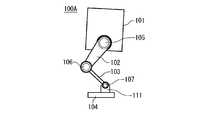
- FIG. 1shows a configuration example of a two-legged mobile robot 100.
- the two-legged mobile robot 100has a main body portion 101, leg portions 102, 103, a foot flat portion 104, and joint portions 105, 106, 107. In the figure, the opposite second leg is not shown.
- the joint portion 105connects the main body portion 101 and the leg portion 102.
- the joint portion 106connects the leg portion 102 and the leg portion 103.
- the joint portion 107connects the leg portion 103 and the palm portion 104.
- Each jointhas an actuator (motor) and an encoder for detecting the position of the actuator.
- a vibration sensoris mounted on the foot flat portion 104.
- each leghas at least 3 degrees of freedom.
- the angle of each leg when moving the tip of the leg at the time of landing and leaving the bedcan be dynamically changed, and the height of the leg raising can be dynamically changed.
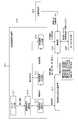
- FIG. 2is a block diagram showing a configuration of a control system of the two-legged mobile robot 100.
- the two-legged mobile robot 100has a road surface information acquisition device 201, a scattering prevention constraint calculation device 202, an action determination unit 203, a control unit 204, and a motor input / output unit 205.
- This control systemis composed of, for example, a computer (microcomputer) arranged in the main body 101. This computer executes the functions of each part of the control system based on the program stored in the ROM, for example.
- a computermicrocomputer
- the road surface information acquisition device 201estimates road surface information (information on the road surface type and road surface depth) based on the vibration information obtained by the vibration sensor mounted on the foot flat portion 104, and further determines the vibration applied to the road surface. Calculate amplitude and frequency.
- the road surface information acquisition device 201includes a sensor input unit 211, a vibration time series holding unit 212, a road surface depth estimation unit 213, a road surface type estimation unit 214, and an applied vibration calculation unit 215.
- the sensor input unit 211inputs vibration information (frequency, amplitude) obtained by the vibration sensor mounted on the foot flat portion 104.
- the vibration time series holding unit 212samples the vibration information (frequency, amplitude) input to the sensor input unit 211 at high speed, and holds the sampling values for the past fixed period as the vibration time series.
- the road surface depth estimation unit 213estimates the road surface depth based on the vibration time series held by the vibration time series holding unit 212.
- the tip of the free legis on the liquid surface based on the vibration time series related to the vibration information obtained by the vibration sensor mounted on the foot flat portion 104 of the free leg (the leg on the side away from the road surface).
- the road surface depthis estimated from the difference between the height of the tip of the leg when it rushes in and the height of the tip of the leg when the tip of the free leg comes into contact with the road surface.
- the road surface type estimation unit 214estimates the road surface type based on the vibration time series held by the vibration time series holding unit 212 and the road surface depth estimated by the road surface depth estimation unit 213. In this case, based on the vibration time series related to the vibration information obtained by the vibration sensor mounted on the foot flat portion 104 of the support leg (the leg on the side of the road surface) and the road surface depth estimated by the estimation unit 213. , Estimate the road surface type.
- the flowchart of FIG. 3shows an example of the road surface type estimation procedure.
- the road surface type estimation unit 214determines in step ST1 whether or not the road surface depth is equal to or greater than the threshold value. When it is determined that the road surface depth is not equal to or more than the threshold value, the road surface type estimation unit 214 determines in step ST2 whether or not there is a water splashing sound at the time of landing.
- the road surface type estimation unit 214determines in step ST3 whether or not the damping at the time of applying vibration is large, that is, whether or not the damping coefficient is larger than the damping coefficient threshold value ⁇ . do.
- the road surface type estimation unit 214estimates that the road surface is a hard road surface in step ST4.
- the road surface type estimation unit 214estimates that the road surface is sand in step ST5.
- the road surface type estimation unit 214determines whether or not the damping at the time of applying vibration is large in step ST4, that is, the damping coefficient is larger than the damping coefficient threshold value ⁇ . Judge whether or not. When the damping is large, the road surface type estimation unit 214 estimates that the road surface is a shallow puddle in step ST7. On the other hand, when the damping is small, the road surface type estimation unit 214 estimates that the road surface is mud in step ST8.
- the road surface type estimation unit 214determines whether or not the damping at the time of applying vibration is large in step ST9, that is, whether the damping coefficient is larger than the damping coefficient threshold value. Judge whether or not. When the damping is large, the road surface type estimation unit 214 estimates that the road surface is a deep puddle in step ST11. On the other hand, when the attenuation is small, the road surface type estimation unit 214 estimates in step ST11 that the road surface has accumulated snow.
- the applied vibration calculation unit 215vibrates to be applied to the road surface based on the vibration time series held by the vibration time series holding unit 212 and the road surface type estimated by the road surface type estimation unit 214. Calculate the amplitude and frequency of. In this case, it is calculated what kind of amplitude and frequency should be given in order to make the estimation of the current road surface type by the road surface type estimation unit 214 more accurate. In this case, it is conceivable to calculate only the amplitude of the vibration or only the frequency of the vibration.
- the scattering prevention constraint calculation device 202calculates the scattering prevention constraint (constraint parameter) based on the road surface depth and the road surface type estimated by the road surface information acquisition device 201.
- This shatterproof constraintincludes leg tip speed constraint when landing, leg tip speed constraint when leaving the bed, leg tip posture angle constraint when landing, leg tip posture angle constraint when leaving the bed, and leg raising height of the free leg. Constraints are included. It is not necessary to include all of these constraints, as long as at least one of these constraints is included.
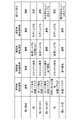
- FIG. 4shows a specific calculation example of the scattering prevention constraint (scattering risk) calculation.
- the leg tip speed at the time of landingis "normal”
- the leg tip posture angle at the time of landingis "normal”
- the leg tip speed at the time of getting out of bedis “normal”
- the leg tip posture angle at the time of leaving the bedis “normal”.
- the constraint parametersare calculated as “normal” and the leg raising height is “normal”.
- the leg tip speed at the time of landingis “slow landing and descending vertically”
- the leg tip posture angle at the time of landingis “landing from the heel”
- the leg tip speed at the time of leaving the bedis “vertically”.
- Constraint parametersare calculated such as “raise, do not kick the sand”, “raise horizontally” for the leg tip posture angle when getting out of bed, and "normal” for the leg raising height.
- the leg tip speed at the time of landingis "slow landing, descend vertically”
- the leg tip posture angle at the time of landingis “landing from the heel”
- the leg tip speed at the time of leaving the bedis “raised vertically”.
- the leg tip posture angle when getting out of bedis “horizontally raised”, and the leg raising height is “normal”, and the respective constraint parameters are calculated.
- the leg tip speed at the time of landingis "slow landing, descend vertically”
- the leg tip posture angle at the time of landingis "water landing from the heel, landing on the surface”
- the leg tip speed at the time of leaving the bedIs "normal”
- the leg tip posture angle when getting out of bedis “normal”
- the leg raising heightis “raising the foot above the depth of water”
- leg tip speed at the time of landingis "landing very slowly and descends vertically”
- leg tip posture angle at the time of landingis “landing from the heel”
- leg tip speed at the time of leaving the bedis “vertically”.
- Constraint parametersare calculated, such as “raise”, the leg tip posture angle when getting out of bed is “horizontally raised”, and the leg raising height is “normal”.
- the foot speed at the time of landingis "vertically lowered”
- the posture angle of the foot at the time of landingis "landing on the surface”
- the foot speed at the time of getting out of bedis "normal”
- the foot at the time of getting out of bedis calculated, such as "normal” for the leg tip posture angle and "raise the foot above the depth of the snow” for the leg raising height.
- the control unit 204determines a signal to be input to the motor (actuator) of each joint and sends it to the motor input / output unit 205.
- the target values applied to the motorare the target angular velocity, the target torque, and the like.
- the control unit 204sets the target value as information such as a target speed and a target gait instructed by the action determination unit 203, information on the amplitude and frequency of vibration to be applied calculated by the road surface information acquisition device 201, and prevention of scattering. It is calculated using the information of the scattering prevention constraint calculated by the constraint calculation device 202.
- Control system processing flowEach leg of the two-legged mobile robot 100 moves in a desired direction by switching between the supporting leg period and the swinging period.
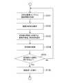
- the flowchart of FIG. 5shows an example of processing of a control system (see FIG. 2) for a leg in the support leg period, that is, the support leg.
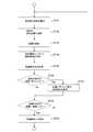
- the flowchart of FIG. 6shows an example of processing of a leg in the swing phase, that is, a control system (see FIG. 2) for the swing leg.
- the processing of the flowcharts of FIGS. 5 and 6is performed during each tick loop.
- step ST21vibration information is acquired from the vibration sensor mounted on the foot flat portion 104 of the support leg.
- step ST22vibration information (frequency, amplitude) is sampled at high speed, and the sampling values for the past fixed period are held as a vibration time series.
- step ST23the amplitude and frequency of the vibration to be applied to the road surface are calculated based on the estimated road surface type and the vibration time series obtained from the vibration information of the vibration sensor of the support leg.
- step ST24the support leg is controlled, that is, the position of the leg for walking is controlled, and the leg (joint) is vibrated in order to apply the vibration of the calculated amplitude and frequency described above to the road surface. ..
- step ST25it is determined whether or not to shift from the support leg to the free leg.
- the processreturns to the process of step ST21, and the same process as described above is repeated.
- the swing phaseshifts in step ST26. In other words, the leg that was the support leg until now becomes a swing leg, and the control flow for the swing leg, that is, the leg in the swing phase is applied.
- step ST31the road surface depth estimated based on the vibration time series obtained from the vibration information of the swing sensor, and the road surface depth and the vibration information of the support leg vibration sensor are obtained.
- the scattering prevention constraintis calculated based on the road surface type estimated based on the vibration time series.
- step ST32the information on the leg tip activation (leg tip speed, leg tip posture angle, leg raising height) is updated based on the calculated anti-scattering constraint. For example, when what used to be a hard road surface changes to a shallow puddle, the scattering prevention constraint is also updated from the hard road surface to a shallow puddle (see FIG. 4). At this time, the leg tip activation is updated from the one corresponding to the hard road surface to the one corresponding to the shallow puddle.
- step ST33the swing leg is controlled, that is, the position of the leg for walking is controlled.
- the leg tip activationis controlled to be the updated leg tip activation described above.
- the leg tip speedis controlled to satisfy "slow landing, vertical lowering" at the time of landing, and the leg tip posture angle is ". It is controlled to satisfy "landing from the heel".
- the leg tip speedis controlled to satisfy "vertically increase” and the leg tip posture angle is "horizontally” when leaving the bed. It is controlled to satisfy "raise”.
- the leg tip activationis updated to correspond to a shallow puddle, the leg raising height after getting out of bed is controlled to satisfy "normal".
- step ST34vibration information is acquired from the vibration sensor mounted on the foot flat portion 104 of the free leg.
- step ST35vibration information (frequency, amplitude) is sampled at high speed, and the sampling values for the past fixed period are held as a vibration time series.
- step ST36it is determined whether or not the tip of the free leg has entered the liquid surface based on the vibration time series obtained from the vibration information of the free leg vibration sensor.
- the height of the leg tip at the time of entering the liquid surfaceis stored in step ST37, and then the process proceeds to step ST38. If it is determined that the liquid has not entered the liquid level, the process immediately proceeds to step ST38.
- step ST38it is determined whether or not the tip of the free leg has come into contact with the road surface based on the vibration time series obtained from the vibration information of the free leg vibration sensor.
- the processreturns to the process of step ST31, and the same process as described above is repeated.
- the support leg periodis entered in step ST39. In other words, the leg that was a free leg until now becomes a support leg, and the control flow for the support leg, that is, the leg in the support leg period is applied.
- the road surface depthis estimated based on the difference between the height of the leg tip when the tip of the free leg rushes into the liquid surface and the height of the tip of the leg when the tip of the free leg comes into contact with the road surface. Will be done.
- the free leghas the leg tip activation (leg tip speed, leg tip posture angle, leg raising height) due to the anti-scattering constraint calculated based on the road surface information (road surface depth, road surface type).
- the information in)is updated, and the activation of the tip of the free leg is controlled according to the update. Therefore, even if there are scattered objects such as water, sand, mud, and snow on the road surface, it is possible to prevent the scattering.
- FIG. 7shows an example in which the activation of the tip of the free leg changes with the update of the anti-scattering constraint.
- FIG. 7Ashows a state when the two-legged mobile robot 100 rushes into a puddle. In this state, the first step is to land in the puddle for the first time from the state where it was not in the puddle until now. At this point, the two-legged mobile robot 100 does not yet know that it has landed in the puddle.
- the arrow in FIG. 7 (b)indicates the initially planned activation of the tip of the free leg.
- the arrow in FIG. 7 (c)indicates the actual activation of the tip of the swing leg, which changes with the update of the anti-scattering constraint.
- the trajectoryis initially the same as the leg tip activation planned at the beginning of FIG. 7 (b).
- the leg launchchanges to be different from the originally planned leg launch to prevent the puddle from splashing. do.
- the leg tip speedchanges to "slow landing and vertical lowering" and the leg tip posture angle changes to "landing from the heel" at the time of landing.
- the movement operationis controlled based on the scattering prevention constraint information acquired based on the road surface information, and water, sand, mud, and the like on the road surface. Even if scattered objects such as snow are present, it is possible to suppress the scattering of those scattered objects due to movement.
- the road surface information(information on the road surface type and the road surface depth) is estimated based on the vibration information obtained by the vibration sensor mounted on the foot flat portion 104.
- the acquisition device 201is provided, and it is possible to acquire road surface information in real time.
- the road surface information acquisition device 201calculates the amplitude and frequency of vibration to be applied to the road surface based on the road surface type information and the vibration time series, and uses the calculation results.
- the jointis vibration-controlled to apply vibration to the road surface, and it is possible to acquire road surface information more accurately based on the vibration information obtained by the vibration sensor.
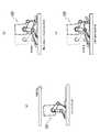
- the vibration informationis detected by the vibration sensor mounted on the foot flat portion 104, but the vibration information is detected by using a force sensor or a microphone instead of the vibration sensor. It is also possible.
- the two-legged mobile robot 100A of FIG. 8shows an example of detecting vibration information with a force sensor 111 mounted on an ankle.
- the parts corresponding to those in FIG. 1are designated by the same reference numerals, and detailed description thereof will be omitted.
- the force sensor 111is configured to detect the vibration information in this way, the force sensor 111 can simultaneously measure the leg tip force of the two-legged mobile robot 100.
- the example of acquiring the road surface information based on the vibration information detected by the vibration sensoris shown, but the road surface information can also be acquired based on other sensor information such as an image sensor. Conceivable.
- a camera (image sensor) 112is attached to the main body 101, and an example of acquiring road surface information based on the image pickup signal of the camera 112 is shown.
- the parts corresponding to those in FIG. 1are designated by the same reference numerals, and detailed description thereof will be omitted.
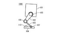
- the two-legged mobile robot 100C of FIG. 10shows an example in which an oscillator 113 is attached to a foot flat portion 104 and the oscillator 113 is vibrated to give vibration to a road surface.
- the parts corresponding to those in FIG. 1are designated by the same reference numerals, and detailed description thereof will be omitted.
- FIG. 11shows, for example, a configuration example of the four-legged mobile robot 100D.
- the parts corresponding to those in FIG. 1are designated by the same reference numerals, and detailed description thereof will be omitted.
- the configuration and processing flow of the control system in this 4-leg mobile robot 100Dare the same as those of the 2-leg mobile robot 100 shown in FIG. 1, although the number of legs is different.
- the road surface informationcan be acquired as in the case of the two-leg mobile robot 100. Based on this, it is possible to move the legs while suppressing scattering.
- leg-moving robotan example of a leg-moving robot is shown, but the present technology can be similarly applied to a mobile robot that moves by using other moving parts such as wheels instead of the legs.
- the technologycan have the following configurations.
- a constraint information acquisition unitthat acquires shatterproof constraint information based on road surface information
- a mobile robotincluding a control unit that controls a movement operation based on the scattering prevention constraint information.
- the mobile robot according to (1) abovefurther comprising a road surface information acquisition unit for acquiring the road surface information.
- (3) Further equipped with a vibration detection unit that detects vibration informationThe mobile robot according to (2), wherein the road surface information acquisition unit acquires the road surface information based on the vibration information.
- the vibration detection unitis configured by using a vibration sensor, a force sensor, or a microphone.
- the mobile robotis a leg mobile robot.
- the vibration applying unitchanges the amplitude or frequency of the applied vibration based on the acquired road surface information.
- the road surface informationincludes information on the type of road surface.
- the mobile robotaccording to (9) above, wherein the road surface information further includes information on the depth of the road surface.
- the mobile robotis a leg mobile robot.
- the shatterproof constraint informationincludes the leg tip speed constraint at the time of landing, the leg tip speed constraint at the time of leaving the bed, the leg tip attitude angle constraint at the time of landing, the leg tip attitude angle constraint at the time of leaving the bed, and the free leg.
Landscapes
- Engineering & Computer Science (AREA)
- Mechanical Engineering (AREA)
- Robotics (AREA)
- Automation & Control Theory (AREA)
- Evolutionary Computation (AREA)
- Artificial Intelligence (AREA)
- Physics & Mathematics (AREA)
- Fuzzy Systems (AREA)
- Mathematical Physics (AREA)
- Software Systems (AREA)
- Human Computer Interaction (AREA)
- Chemical & Material Sciences (AREA)
- Combustion & Propulsion (AREA)
- Transportation (AREA)
- Manipulator (AREA)
Abstract
Description
Translated fromJapanese本技術は、移動ロボット、移動ロボットの制御方法およびプログラムに関し、詳しくは、移動に伴う水、砂、泥、雪等の飛散物の飛散を防ぐようにした移動ロボット等に関する。This technology relates to mobile robots, control methods and programs for mobile robots, and more specifically to mobile robots that prevent scattering of scattered objects such as water, sand, mud, and snow that accompany movement.
従来、脚移動ロボット等の移動ロボットが提案されている。移動ロボットが屋外を移動する際、路面に水、砂、泥、雪等の飛散物がある場合には、それらの飛散物が飛散させて、人やその他の物にかけてしまうことも想定される。Conventionally, mobile robots such as leg mobile robots have been proposed. When a mobile robot moves outdoors, if there are scattered objects such as water, sand, mud, and snow on the road surface, it is assumed that those scattered objects will be scattered and thrown at people or other objects.
例えば、特許文献1には、前方路面の勾配、凹凸、濡れ等に基づいて歩容(トロット、クロール)を切り替える歩行ロボット装置が開示されている。しかし、この特許文献1には、路面に水、砂、泥、雪等の飛散物がある場合に、それらの飛散物を飛散させないようにすることについては言及されていない。For example, Patent Document 1 discloses a walking robot device that switches gaits (trots, crawls) based on the gradient, unevenness, wetness, etc. of the front road surface. However, this Patent Document 1 does not mention that when there are scattered objects such as water, sand, mud, and snow on the road surface, the scattered objects are prevented from being scattered.
本技術の目的は、移動に伴う水、砂、泥、雪等の飛散物の飛散を防ぐことにある。The purpose of this technology is to prevent the scattering of scattered objects such as water, sand, mud, and snow due to movement.
本技術の概念は、
路面情報に基づいて飛散防止制約情報を取得する制約情報取得部と、
前記飛散防止制約情報に基づいて移動動作を制御する制御部を備える
移動ロボットにある。The concept of this technology is
A constraint information acquisition unit that acquires shatterproof constraint information based on road surface information,
It is in a mobile robot provided with a control unit that controls a movement operation based on the scattering prevention constraint information.
本技術において、取得部により、路面情報に基づいて飛散防止制約情報が取得される。例えば、路面情報は、路面の種類の情報を含む、ようにされてもよい。この場合例えば、路面情報は、路面の深さの情報をさらに含む、ようにされてもよい。制御部により、飛散防止制約情報に基づいて移動動作が制御される。In this technology, the acquisition unit acquires the scattering prevention constraint information based on the road surface information. For example, the road surface information may be adapted to include information on the type of road surface. In this case, for example, the road surface information may be adapted to further include information on the depth of the road surface. The control unit controls the movement operation based on the scattering prevention constraint information.
例えば、路面情報を取得する路面情報取得部をさらに備える、ようにされてもよい。このように路面情報取得部を備えることで、路面情報をリアルタイムに取得することが可能となる。この場合、例えば、振動情報を検出する振動検出部をさらに備え、路面情報取得部は、振動情報に基づいて路面情報を取得する、ようにされてもよい。ここで、振動検出部は、例えば、振動センサ、力覚センサまたはマイクロホンを用いて構成されてもよい。For example, a road surface information acquisition unit for acquiring road surface information may be further provided. By providing the road surface information acquisition unit in this way, it is possible to acquire road surface information in real time. In this case, for example, a vibration detection unit for detecting vibration information may be further provided, and the road surface information acquisition unit may be configured to acquire road surface information based on the vibration information. Here, the vibration detection unit may be configured by using, for example, a vibration sensor, a force sensor, or a microphone.
例えば、路面に振動を付与する振動付与部をさらに備える、ようにされてもよい。このように振動付与部を備えることで、振動情報に基づいて路面情報を良好に取得することが可能となる。この場合、例えば、移動ロボットは、脚移動ロボットであり、振動付与部は、脚の関節を振動させることで路面に振動を与える、ようにされてもよい。また、この場合、例えば、振動付与部は、振動子を用いて路面に振動を与える、ようにされてもよい。For example, a vibration applying portion that applies vibration to the road surface may be further provided. By providing the vibration imparting portion in this way, it is possible to satisfactorily acquire road surface information based on the vibration information. In this case, for example, the mobile robot may be a leg moving robot, and the vibration applying portion may be configured to give vibration to the road surface by vibrating the joints of the legs. Further, in this case, for example, the vibration applying portion may be configured to give vibration to the road surface by using a vibrator.
また、この場合、例えば、振動付与部は、取得された路面情報に基づいて付与する振動の振幅または周波数を変化させる、ようにされてもよい。これにより、振動情報に基づいて認識される路面情報の精度を高めることが可能となる。Further, in this case, for example, the vibration applying unit may be configured to change the amplitude or frequency of the vibration applied based on the acquired road surface information. This makes it possible to improve the accuracy of the road surface information recognized based on the vibration information.
例えば、移動ロボットは、脚移動ロボットであり、制御部は、脚移動を制御する、ようにされてもよい。この場合、例えば、飛散防止制約情報は、着床時の脚先速度制約、離床時の脚先速度制約、着床時の脚先姿勢角制約、離床時の脚先姿勢角制約、および遊脚の脚上げ高さ制約の少なくともいずれかの制約の情報を含む、ようにされてもよい。For example, the mobile robot may be a leg moving robot, and the control unit may control the leg movement. In this case, for example, the anti-scattering constraint information includes the leg tip speed constraint at the time of landing, the leg tip speed constraint at the time of leaving the bed, the leg tip posture angle constraint at the time of landing, the leg tip posture angle constraint at the time of leaving the bed, and the free leg. It may be configured to include information on at least one of the leg-raising height constraints.
このように本技術においては、路面情報に基づいて取得された飛散防止制約情報に基づいて移動動作を制御するものである。そのため、移動に伴う水、砂、泥、雪等の飛散物の飛散を防ぐことが可能となる。As described above, in this technology, the movement operation is controlled based on the scattering prevention constraint information acquired based on the road surface information. Therefore, it is possible to prevent the scattering of scattered objects such as water, sand, mud, and snow due to the movement.
以下、発明を実施するための形態(以下、「実施の形態」とする)について説明する。なお、説明を以下の順序で行う。
1.実施の形態
2.変形例Hereinafter, embodiments for carrying out the invention (hereinafter referred to as “embodiments”) will be described. The explanations will be given in the following order.
1. 1. Embodiment 2. Modification example
<1.実施の形態>
「脚移動ロボットの外観」
図1は、2脚移動ロボット100の構成例を示している。この2脚移動ロボット100は、本体部101と、脚部102,103と、足平部104と、関節部105,106,107を有している。図では、対向する2本目の脚は図示されていない。<1. Embodiment>
"Appearance of a leg-moving robot"
FIG. 1 shows a configuration example of a two-legged
関節部105は、本体部101と脚部102を接続している。関節部106は、脚部102と脚部103を接続している。関節部107は、脚部103と足平部104を接続している。各関節部は、アクチュエータ(モータ)と、アクチュエータの位置を検出するためのエンコーダを持っている。足平部104には、振動センサが搭載されている。The
各脚は、3自由度以上あることが望ましい。また、各脚は、着床時、離床時の脚先移動時の角度が動的に変えられると共に、脚上げ高さが動的に変えられる、また、各脚は、接地時に接地脚(支持脚)の関節を振動させることで、接地面に振動を印加可能である。It is desirable that each leg has at least 3 degrees of freedom. In addition, the angle of each leg when moving the tip of the leg at the time of landing and leaving the bed can be dynamically changed, and the height of the leg raising can be dynamically changed. By vibrating the joints of the legs), vibration can be applied to the ground contact surface.
「脚移動ロボットの制御系の構成」
図2は、2脚移動ロボット100の制御系の構成を示すブロック図である。2脚移動ロボット100は、路面情報取得装置201と、飛散防止制約計算装置202と、行動決定部203と、制御部204と、モータ入出力部205を有している。この制御系は、例えば本体部101に配設されているコンピュータ(マイコン)により構成されている。このコンピュータは、例えばROMに格納されているプログラムに基づいて制御系の各部の機能を実行する。"Structure of control system of leg mobile robot"
FIG. 2 is a block diagram showing a configuration of a control system of the two-legged
路面情報取得装置201は、足平部104に搭載された振動センサで得られた振動情報に基づいて、路面情報(路面種類と路面深さの情報)を推定し、さらに路面に印加する振動の振幅や周波数を計算する。The road surface
路面情報取得装置201は、センサ入力部211と、振動時系列保持部212と、路面深さ推定部213と、路面種類推定部214と、印加振動計算部215を有している。センサ入力部211は、足平部104に搭載された振動センサで得られた振動情報(周波数、振幅)を入力する。振動時系列保持部212は、センサ入力部211に入力された振動情報(周波数、振幅)を高速でサンプリングし、過去一定期間のサンプリング値を振動時系列として保持する。The road surface
路面深さ推定部213は、振動時系列保持部212に保持されている振動時系列に基づいて、路面深さを推定する。この場合、遊脚(路面から離れている側の脚)の足平部104に搭載された振動センサで得られた振動情報に係る振動時系列に基づいて、遊脚の脚先が液面に突入した際の脚先高さと遊脚の脚先が路面に接触した際の脚先高さの差から、路面深さを推定する。The road surface
路面種類推定部214は、振動時系列保持部212に保持されている振動時系列と、路面深さ推定部213で推定された路面深さに基づいて、路面種類を推定する。この場合、支持脚(路面に着いている側の脚)の足平部104に搭載された振動センサで得られた振動情報に係る振動時系列と推定部213で推定された路面深さに基づき、路面種類を推定する。The road surface
図3のフローチャートは、路面種類の推定手順の一例を示している。まず、路面種類推定部214は、ステップST1において、路面深さが閾値以上か否かを判断する。路面深さが閾値以上でないと判断するとき、路面種類推定部214は、ステップST2において、着床時に水撥ね音があったか否かを判断する。The flowchart of FIG. 3 shows an example of the road surface type estimation procedure. First, the road surface
着床時に水撥ね音がなかったと判断するとき、路面種類推定部214は、ステップST3において、振動印加時の減衰が大きいか否か、つまり減衰係数が減衰係数閾値αより大きいか否かを判断する。減衰が小さいとき、路面種類推定部214は、ステップST4において、路面は硬い路面である、と推定する。一方、減衰が大きいとき、路面種類推定部214は、ステップST5において、路面は砂である、と推定する。When it is determined that there is no water splashing sound at the time of landing, the road surface
また、ステップST2で着床時に水撥ね音があったと判断するとき、路面種類推定部214は、ステップST4において、振動印加時の減衰が大きいか否か、つまり減衰係数が減衰係数閾値βより大きいか否かを判断する。減衰が大きいとき、路面種類推定部214は、ステップST7において、路面は浅い水たまりである、と推定する。一方、減衰が小さいとき、路面種類推定部214は、ステップST8において、路面は泥である、と推定する。Further, when it is determined in step ST2 that there was a water splashing sound at the time of landing, the road surface
また、ステップST1で路面深さが閾値以上あったと判断するとき、路面種類推定部214は、ステップST9において、振動印加時の減衰が大きいか否か、つまり減衰係数が減衰係数閾値?より大きいか否かを判断する。減衰が大きいとき、路面種類推定部214は、ステップST11において、路面は深い水たまりである、と推定する。一方、減衰が小さいとき、路面種類推定部214は、ステップST11において、路面は積もった雪ある、と推定する。Further, when it is determined in step ST1 that the road surface depth is equal to or greater than the threshold value, the road surface
図2に戻って、印加振動計算部215は、振動時系列保持部212に保持されている振動時系列と、路面種類推定部214で推定された路面種類に基づいて、路面に印加すべき振動の振幅および周波数を計算する。この場合、路面種類推定部214における現在の路面種類の推定をより正しくするためにどのような振幅および周波数を与えればよいかを計算する。なお、この場合、振動の振幅のみ、あるいは振動の周波数のみを計算することも考えられる。Returning to FIG. 2, the applied
飛散防止制約計算装置202は、路面情報取得装置201で推定された路面深さと路面種類に基づいて、飛散防止制約(制約パラメータ)を計算する。この飛散防止制約には、着床時の脚先速度制約、離床時の脚先速度制約、着床時の脚先姿勢角制約、離床時の脚先姿勢角制約、遊脚の脚上げ高さ制約が含まれる。なお、これらの制約の全てを含む必要はなく、少なくともいずれかの制約が含まれていればよい。The scattering prevention
図4は、飛散防止制約(飛散リスク)計算の具体的な計算例を示している。例えば、路面が硬い路面である場合、着床時脚先速度は「通常」、着床時脚先姿勢角は「通常」、離床時脚先速度は「通常」、離床時脚先姿勢角は「通常」、脚上げ高さは「通常」と、それぞれの制約パラメータが計算される。FIG. 4 shows a specific calculation example of the scattering prevention constraint (scattering risk) calculation. For example, when the road surface is hard, the leg tip speed at the time of landing is "normal", the leg tip posture angle at the time of landing is "normal", the leg tip speed at the time of getting out of bed is "normal", and the leg tip posture angle at the time of leaving the bed is "normal". The constraint parameters are calculated as "normal" and the leg raising height is "normal".
また、例えば、路面が砂である場合、着床時脚先速度は「ゆっくり着地、鉛直に下す」、着床時脚先姿勢角は「かかとから着地」、離床時脚先速度は「鉛直に上げる、砂を蹴らない」、離床時脚先姿勢角は「水平に上げる」、脚上げ高さは「通常」と、それぞれの制約パラメータが計算される。For example, when the road surface is sandy, the leg tip speed at the time of landing is "slow landing and descending vertically", the leg tip posture angle at the time of landing is "landing from the heel", and the leg tip speed at the time of leaving the bed is "vertically". Constraint parameters are calculated such as "raise, do not kick the sand", "raise horizontally" for the leg tip posture angle when getting out of bed, and "normal" for the leg raising height.
また、例えば、浅い水たまりである場合、着床時脚先速度は「ゆっくり着地、鉛直に下す」、着床時脚先姿勢角は「かかとから着地」、離床時脚先速度は「鉛直に上げる」、離床時脚先姿勢角は「水平に上げる」、脚上げ高さは「通常」と、それぞれの制約パラメータが計算される。Also, for example, in the case of a shallow puddle, the leg tip speed at the time of landing is "slow landing, descend vertically", the leg tip posture angle at the time of landing is "landing from the heel", and the leg tip speed at the time of leaving the bed is "raised vertically". , The leg tip posture angle when getting out of bed is "horizontally raised", and the leg raising height is "normal", and the respective constraint parameters are calculated.
また、例えば、深い水たまりである場合、着床時脚先速度は「ゆっくり着地、鉛直に下す」、着床時脚先姿勢角は「かかとから着水、面で着地」、離床時脚先速度は「通常」、離床時脚先姿勢角は「通常」、脚上げ高さは「水の深さ以上に足を上げる」と、それぞれの制約パラメータが計算される。Also, for example, in the case of a deep puddle, the leg tip speed at the time of landing is "slow landing, descend vertically", the leg tip posture angle at the time of landing is "water landing from the heel, landing on the surface", and the leg tip speed at the time of leaving the bed. Is "normal", the leg tip posture angle when getting out of bed is "normal", and the leg raising height is "raising the foot above the depth of water", and the respective constraint parameters are calculated.
また、例えば、泥である場合、着床時脚先速度は「非常にゆっくり着地、鉛直に下す」、着床時脚先姿勢角は「かかとから着地」、離床時脚先速度は「鉛直に上げる」、離床時脚先姿勢角は「水平に上げる」、脚上げ高さは「通常」と、それぞれの制約パラメータが計算される。Also, for example, in the case of mud, the leg tip speed at the time of landing is "landing very slowly and descends vertically", the leg tip posture angle at the time of landing is "landing from the heel", and the leg tip speed at the time of leaving the bed is "vertically". Constraint parameters are calculated, such as "raise", the leg tip posture angle when getting out of bed is "horizontally raised", and the leg raising height is "normal".
また、例えば、積もった雪である場合、着床時脚先速度は「鉛直に下す」、着床時脚先姿勢角は「面で着地」、離床時脚先速度は「通常」、離床時脚先姿勢角は「通常」、脚上げ高さは「雪の深さ以上に足を上げる」と、それぞれの制約パラメータが計算される。Also, for example, in the case of accumulated snow, the foot speed at the time of landing is "vertically lowered", the posture angle of the foot at the time of landing is "landing on the surface", the foot speed at the time of getting out of bed is "normal", and the foot at the time of getting out of bed. Each constraint parameter is calculated, such as "normal" for the leg tip posture angle and "raise the foot above the depth of the snow" for the leg raising height.
図2に戻って、制御部204は、各関節のモータ(アクチュエータ)に入力する信号を決定し、モータ入出力部205に送る。この場合、モータに印加する目標値は、目標角速度、目標トルク等である。制御部204は、この目標値を、行動決定部203によって指示された目標速度や目標歩容などの情報、路面情報取得装置201で計算された印加すべき振動の振幅や周波数の情報、飛散防止制約計算装置202で計算された飛散防止制約の情報、を用いて計算する。Returning to FIG. 2, the
「制御系の処理フロー」
2脚移動ロボット100のそれぞれの脚は支持脚期と遊脚期を切り替えることで所望の方向に移動する。図5のフローチャートは、支持脚期にある脚、つまり支持脚に対する制御系(図2参照)の処理の一例を示している。図6のフローチャートは、遊脚期にある脚、つまり遊脚に対する制御系(図2参照)の処理の一例を示している。これら図5および図6のフローチャートの処理は、毎ティックのループ時に行われる。"Control system processing flow"
Each leg of the two-legged
図5のフローチャートを参照して支持脚、つまり支持脚期にある脚に対する制御フローについて説明する。まず、ステップST21において、支持脚の足平部104に搭載されている振動センサから振動情報を取得する。次に、ステップST22において、振動情報(周波数、振幅)を高速でサンプリングし、過去一定期間のサンプリング値を振動時系列として保持する。The control flow for the support leg, that is, the leg in the support leg period will be described with reference to the flowchart of FIG. First, in step ST21, vibration information is acquired from the vibration sensor mounted on the foot
次に、ステップST23において、推定された路面種類と、支持脚の振動センサの振動情報で得られた振動時系列に基づいて、路面に印加すべき振動の振幅および周波数を算出する。次に、ステップST24において、支持脚の制御、つまり歩くための脚の位置の制御と、上述の算出された振幅および周波数の振動を路面に印加するために脚(関節)を振動させる制御をする。Next, in step ST23, the amplitude and frequency of the vibration to be applied to the road surface are calculated based on the estimated road surface type and the vibration time series obtained from the vibration information of the vibration sensor of the support leg. Next, in step ST24, the support leg is controlled, that is, the position of the leg for walking is controlled, and the leg (joint) is vibrated in order to apply the vibration of the calculated amplitude and frequency described above to the road surface. ..
次に、ステップST25において、支持脚から遊脚に移行するか否かを判断する。この場合、遊脚の脚先が路面に接触した場合には、支持脚から遊脚に移行すると判断する。支持脚から遊脚に移行しないと判断するとき、ステップST21の処理に戻り、上述したと同様の処理を繰り返し行う。一方、支持脚から遊脚に移行すると判断するとき、ステップST26において、遊脚期に移行する。つまり、今まで支持脚だった脚は遊脚となって、遊脚、つまり遊脚期にある脚に対する制御フローが適用される状態となる。Next, in step ST25, it is determined whether or not to shift from the support leg to the free leg. In this case, when the tip of the swing leg comes into contact with the road surface, it is determined that the support leg shifts to the swing leg. When it is determined that the support leg does not shift to the swing leg, the process returns to the process of step ST21, and the same process as described above is repeated. On the other hand, when it is determined that the support leg shifts to the swing leg, the swing phase shifts in step ST26. In other words, the leg that was the support leg until now becomes a swing leg, and the control flow for the swing leg, that is, the leg in the swing phase is applied.
図6のフローチャートを参照して、遊脚、つまり遊脚期にある脚に対する制御フローについて説明する。まず、ステップST31において、後述するように遊脚の振動センサの振動情報で得られた振動時系列に基づいて推定された路面深さと、この路面深さと支持脚の振動センサの振動情報で得られた振動時系列に基づいて推定された路面種類に基づいて、飛散防止制約を算出する。The control flow for the swing leg, that is, the leg in the swing phase, will be described with reference to the flowchart of FIG. First, in step ST31, as will be described later, the road surface depth estimated based on the vibration time series obtained from the vibration information of the swing sensor, and the road surface depth and the vibration information of the support leg vibration sensor are obtained. The scattering prevention constraint is calculated based on the road surface type estimated based on the vibration time series.
次に、ステップST32において、算出された飛散防止制約に基づいて、脚先起動(脚先速度、脚先姿勢角、脚上げ高さ)の情報を更新する。例えば、今まで硬い路面であったものが浅い水たまりに変化すると、飛散防止制約も硬い路面のものから浅い水たまりのものに更新される(図4参照)。このとき、脚先起動は、硬い路面に対応したものから浅い水たまりに対応したものに更新される。Next, in step ST32, the information on the leg tip activation (leg tip speed, leg tip posture angle, leg raising height) is updated based on the calculated anti-scattering constraint. For example, when what used to be a hard road surface changes to a shallow puddle, the scattering prevention constraint is also updated from the hard road surface to a shallow puddle (see FIG. 4). At this time, the leg tip activation is updated from the one corresponding to the hard road surface to the one corresponding to the shallow puddle.
次に、ステップST33において、遊脚の制御、つまり歩くための脚の位置を制御する。この場合、脚先起動は、上述の更新された脚先起動となるように制御される。例えば、脚先起動が浅い水たまりに対応したものに更新されたとき、着床時にあっては、脚先速度は「ゆっくり着地、鉛直におろす」を満たすように制御され、脚先姿勢角は「かかとから着地」を満たすように制御される。Next, in step ST33, the swing leg is controlled, that is, the position of the leg for walking is controlled. In this case, the leg tip activation is controlled to be the updated leg tip activation described above. For example, when the leg tip activation is updated to correspond to a shallow puddle, the leg tip speed is controlled to satisfy "slow landing, vertical lowering" at the time of landing, and the leg tip posture angle is ". It is controlled to satisfy "landing from the heel".
また、例えば、脚先起動が浅い水たまりに対応したものに更新されたとき、離床時にあっては、脚先速度は「鉛直に上げる」を満たすように制御され、脚先姿勢角は「水平に上げる」を満たすように制御される。また、例えば、脚先起動が浅い水たまりに対応したものに更新されたとき、離床した後の脚上げ高さは「通常」を満たすように制御される。Also, for example, when the leg tip activation is updated to correspond to a shallow puddle, the leg tip speed is controlled to satisfy "vertically increase" and the leg tip posture angle is "horizontally" when leaving the bed. It is controlled to satisfy "raise". Further, for example, when the leg tip activation is updated to correspond to a shallow puddle, the leg raising height after getting out of bed is controlled to satisfy "normal".
次に、ステップST34において、遊脚の足平部104に搭載されている振動センサから振動情報を取得する。次に、ステップST35において、振動情報(周波数、振幅)を高速でサンプリングし、過去一定期間のサンプリング値を振動時系列として保持する。Next, in step ST34, vibration information is acquired from the vibration sensor mounted on the foot
次に、ステップST36において、遊脚の振動センサの振動情報で得られた振動時系列に基づいて、遊脚の脚先が液面に突入したか否かを判断する。液面に突入したと判断するとき、ステップST37において、液面に突入した際の脚先高さを保存し、その後にステップST38に進む。液面に突入していないと判断するときは、直ちに、ステップST38に進む。Next, in step ST36, it is determined whether or not the tip of the free leg has entered the liquid surface based on the vibration time series obtained from the vibration information of the free leg vibration sensor. When it is determined that the product has entered the liquid surface, the height of the leg tip at the time of entering the liquid surface is stored in step ST37, and then the process proceeds to step ST38. If it is determined that the liquid has not entered the liquid level, the process immediately proceeds to step ST38.
次に、ステップST38において、遊脚の振動センサの振動情報で得られた振動時系列に基づいて、遊脚の脚先が路面に接触したか否かを判断する。路面に接触していないと判断するとき、ステップST31の処理に戻り、上述したと同様の処理を繰り返し行う。一方、路面に接触したと判断するとき、ステップST39において、支持脚期に移行する。つまり、今まで遊脚だった脚は支持脚となって、支持脚、つまり支持脚期にある脚に対する制御フローが適用される状態となる。Next, in step ST38, it is determined whether or not the tip of the free leg has come into contact with the road surface based on the vibration time series obtained from the vibration information of the free leg vibration sensor. When it is determined that the vehicle is not in contact with the road surface, the process returns to the process of step ST31, and the same process as described above is repeated. On the other hand, when it is determined that the vehicle has come into contact with the road surface, the support leg period is entered in step ST39. In other words, the leg that was a free leg until now becomes a support leg, and the control flow for the support leg, that is, the leg in the support leg period is applied.
なお、遊脚の脚先が液面に突入した液面に突入した際の脚先高さと遊脚の脚先が路面に接触した際の脚先高さとの差に基づいて路面深さが推定される。The road surface depth is estimated based on the difference between the height of the leg tip when the tip of the free leg rushes into the liquid surface and the height of the tip of the leg when the tip of the free leg comes into contact with the road surface. Will be done.
図6のフローチャートで示すように、遊脚は、路面情報(路面深さ、路面種類)に基づいて算出された飛散防止制約により、脚先起動(脚先速度、脚先姿勢角、脚上げ高さ)の情報が更新されて、その更新に応じて遊脚の脚先起動が制御される。そのため、路面に水、砂、泥、雪等の飛散物が存在する場合にあっても、その飛散を防ぐことが可能となる。As shown in the flowchart of FIG. 6, the free leg has the leg tip activation (leg tip speed, leg tip posture angle, leg raising height) due to the anti-scattering constraint calculated based on the road surface information (road surface depth, road surface type). The information in) is updated, and the activation of the tip of the free leg is controlled according to the update. Therefore, even if there are scattered objects such as water, sand, mud, and snow on the road surface, it is possible to prevent the scattering.
図7は、飛散防止制約の更新に伴って遊脚の脚先起動が変化する例を示している。図7(a)は、2脚移動ロボット100が水たまりに突入した時の状態を示している。この状態は、今まで水たまりにいなかった状態から、初めて一歩目が水たまりに着水した状態である。この時点で、2脚移動ロボット100は、まだ水たまりに着水したことを分かっていない。FIG. 7 shows an example in which the activation of the tip of the free leg changes with the update of the anti-scattering constraint. FIG. 7A shows a state when the two-legged
図7(b)の矢印は、最初に計画していた遊脚の脚先起動を示している。図7(c)の矢印は、飛散防止制約の更新に伴って変化する実際の遊脚の脚先起動を示している。この場合、初期は図7(b)の最初に計画していた脚先起動と同じ軌道となる。しかし、その後に飛散防止制約が水たまりに対応するものに更新されるため、脚先起動は、水たまりの水の飛散を防止するように、最初に計画していた脚先起動とは異なるように変化する。この場合は、例えば、浅い水たまりであるときは、着床時において、脚先速度は「ゆっくり着地、鉛直に下ろす」に変化し、脚先姿勢角は「かかとから着地」に変化する。The arrow in FIG. 7 (b) indicates the initially planned activation of the tip of the free leg. The arrow in FIG. 7 (c) indicates the actual activation of the tip of the swing leg, which changes with the update of the anti-scattering constraint. In this case, the trajectory is initially the same as the leg tip activation planned at the beginning of FIG. 7 (b). However, since the anti-scattering constraint is subsequently updated to correspond to the puddle, the leg launch changes to be different from the originally planned leg launch to prevent the puddle from splashing. do. In this case, for example, in the case of a shallow puddle, the leg tip speed changes to "slow landing and vertical lowering" and the leg tip posture angle changes to "landing from the heel" at the time of landing.
以上説明したように、図1に示す2脚移動ロボット100においては、路面情報に基づいて取得された飛散防止制約情報に基づいて移動動作を制御するものであり、路面に水、砂、泥、雪等の飛散物が存在していでも、移動に伴うそれらの飛散物の飛散を抑制することが可能となる。As described above, in the two-legged
また、図1に示す2脚移動ロボット100においては、足平部104に搭載された振動センサで得られた振動情報に基づいて路面情報(路面種類と路面深さの情報)を推定する路面情報取得装置201を備えるものであり、路面情報をリアルタイムに取得することが可能となる。Further, in the two-legged
また、図1に示す2脚移動ロボット100においては、路面情報取得装置201において路面種類の情報や振動時系列に基づいて路面に付与すべき振動の振幅、周波数を計算し、その計算結果を用いて関節を振動制御して路面に振動を付与するものであり、振動センサで得られる振動情報に基づいてより正確に路面情報を取得することが可能となる。Further, in the two-legged
<2.変形例>
なお、上述実施の形態においては、足平部104に搭載された振動センサで得られた振動情報に基づいてリアルタイムに取得される路面情報(路面種類と路面深さの情報)を用いる例を示した。しかし、2脚移動ロボット100の移動経路に対応した路面情報を予め与えておいて、それを使用することも考えられる。<2. Modification example>
In the above-described embodiment, an example of using road surface information (information on the road surface type and road surface depth) acquired in real time based on the vibration information obtained by the vibration sensor mounted on the foot
また、上述実施の形態においては、足平部104に搭載された振動センサで振動情報を検出する例を示したが、振動センサの代わりに、力覚センサやマイクロホンを用いて振動情報を検出することも考えられる。Further, in the above-described embodiment, the vibration information is detected by the vibration sensor mounted on the foot
図8の2脚移動ロボット100Aは、足首に搭載されている力覚センサ111で振動情報を検出する例を示している。この図8において、図1と対応する部分には同一符号を付して示し、その詳細説明は省略する。このように力覚センサ111で振動情報を検出する構成とした場合、この力覚センサ111で2脚移動ロボット100の脚先力の計測も同時に行うことが可能となる。The two-legged
また、上述実施の形態においては、振動センサで検出される振動情報に基づいて路面情報を取得する例を示したが、イメージセンサ等のその他のセンサ情報に基づいて、路面情報を取得することも考えられる。Further, in the above-described embodiment, the example of acquiring the road surface information based on the vibration information detected by the vibration sensor is shown, but the road surface information can also be acquired based on other sensor information such as an image sensor. Conceivable.
図9の2脚移動ロボット100Bは、本体部101にカメラ(イメージセンサ)112が取り付けられており、このカメラ112の撮像信号に基づいて路面情報を取得する例を示している。この図9において、図1と対応する部分には同一符号を付して示し、その詳細説明は省略する。In the two-legged
また、上述実施の形態においては、関節を振動させることで路面に振動を付与する(印加する)例を示したが、その他の構成で、路面に振動を付与することも考えられる。図10の2脚移動ロボット100Cは、足平部104に振動子113を取り付け、この振動子113を振動させて路面に振動を付与する例を示している。この図10において、図1と対応する部分には同一符号を付して示し、その詳細説明は省略する。Further, in the above-described embodiment, an example of applying (applying) vibration to the road surface by vibrating the joint is shown, but it is also conceivable to apply vibration to the road surface with other configurations. The two-legged mobile robot 100C of FIG. 10 shows an example in which an
また、上述実施の形態においては、2脚移動ロボットの例を示したものであるが、本技術は2脚以外の脚移動ロボットにも同様に適用可能である。図11は、例えば、4脚移動ロボット100Dの構成例を示している。この図11において、図1と対応する部分には同一符号を付して示し、その詳細説明は省略する。Further, in the above-described embodiment, an example of a two-legged mobile robot is shown, but this technology can be similarly applied to a leg-moving robot other than two-legged. FIG. 11 shows, for example, a configuration example of the four-legged
この4脚移動ロボット100Dにおける制御系の構成や処理フローは、脚の本数は異なるが、図1に示す2脚移動ロボット100と同様となる。この場合、それぞれの遊脚、支持脚に対して図5、図6の支持脚、遊脚に対する処理フローが実行されることで、2脚移動ロボット100の場合と同様に、路面情報の取得とそれに基づいた飛散を抑えた脚移動が可能となる。The configuration and processing flow of the control system in this 4-leg
また、上述実施の形態においては、脚移動ロボットの例を示したが、本技術は、脚ではなく、その他の移動部、例えば車輪等を使って移動する移動ロボットにも同様に適用できる。Further, in the above-described embodiment, an example of a leg-moving robot is shown, but the present technology can be similarly applied to a mobile robot that moves by using other moving parts such as wheels instead of the legs.
また、添付図面を参照しながら本開示の好適な実施形態について詳細に説明したが、本開示の技術的範囲はかかる例に限定されない。本開示の技術分野における通常の知識を有する者であれば、特許請求の範囲に記載された技術的思想の範疇内において、各種の変更例または修正例に想到し得ることは明らかであり、これらについても、当然に本開示の技術的範囲に属するものと了解される。Although the preferred embodiments of the present disclosure have been described in detail with reference to the accompanying drawings, the technical scope of the present disclosure is not limited to such examples. It is clear that anyone with ordinary knowledge in the art of the present disclosure may come up with various modifications or amendments within the scope of the technical ideas set forth in the claims. Is, of course, understood to belong to the technical scope of the present disclosure.
また、本明細書に記載された効果は、あくまで説明的または例示的なものであって限定的ではない。つまり、本開示に係る技術は、上記の効果とともに、または上記の効果に代えて、本明細書の記載から当業者には明らかな他の効果を奏しうる。Further, the effects described in the present specification are merely explanatory or exemplary and are not limited. That is, the technique according to the present disclosure may exert other effects apparent to those skilled in the art from the description of the present specification, in addition to or in place of the above effects.
また、技術は、以下のような構成もとることができる。
(1)路面情報に基づいて飛散防止制約情報を取得する制約情報取得部と、
前記飛散防止制約情報に基づいて移動動作を制御する制御部を備える
移動ロボット。
(2)前記路面情報を取得する路面情報取得部をさらに備える
前記(1)に記載の移動ロボット。
(3)振動情報を検出する振動検出部をさらに備え、
前記路面情報取得部は、前記振動情報に基づいて前記路面情報を取得する
前記(2)に記載の移動ロボット。
(4)前記振動検出部は、振動センサ、力覚センサまたはマイクロホンを用いて構成される
前記(3)に記載の移動ロボット。
(5)前記路面に振動を付与する振動付与部をさらに備える
前記(3)または(4)に記載の移動ロボット。
(6)前記移動ロボットは、脚移動ロボットであり、
前記振動付与部は、脚の関節を振動させることで前記路面に振動を与える
前記(5)に記載の移動ロボット。
(7)前記振動付与部は、振動子を用いて前記路面に振動を与える
前記(5)に記載の移動ロボット。
(8)前記振動付与部は、前記取得された路面情報に基づいて前記付与する振動の振幅または周波数を変化させる
前記(5)から(7)のいずれかに記載の移動ロボット。
(9)前記路面情報は、路面の種類の情報を含む
前記(1)から(8)のいずれかに記載の移動ロボット。
(10)前記路面情報は、路面の深さの情報をさらに含む
前記(9)に記載の移動ロボット。
(11)前記移動ロボットは、脚移動ロボットであり、
前記制御部は、脚移動を制御する
前記(1)から(10)のいずれかに記載の移動ロボット。
(12)前記飛散防止制約情報は、着床時の脚先速度制約、離床時の脚先速度制約、着床時の脚先姿勢角制約、離床時の脚先姿勢角制約、および遊脚の脚上げ高さ制約の少なくともいずれかの制約の情報を含む
前記(11)に記載の移動ロボット。
(13)路面情報に基づいて飛散防止制約情報を取得する手順と、
前記飛散防止制約情報に基づいて移動動作を制御する手順を有する
移動ロボットの制御方法。
(14)コンピュータを、
路面情報に基づいて飛散防止制約情報を取得する取得手段と、
前記飛散防止制約情報に基づいて移動ロボットの移動動作を制御する制御種手段として機能させる
プログラム。In addition, the technology can have the following configurations.
(1) A constraint information acquisition unit that acquires shatterproof constraint information based on road surface information,
A mobile robot including a control unit that controls a movement operation based on the scattering prevention constraint information.
(2) The mobile robot according to (1) above, further comprising a road surface information acquisition unit for acquiring the road surface information.
(3) Further equipped with a vibration detection unit that detects vibration information,
The mobile robot according to (2), wherein the road surface information acquisition unit acquires the road surface information based on the vibration information.
(4) The mobile robot according to (3) above, wherein the vibration detection unit is configured by using a vibration sensor, a force sensor, or a microphone.
(5) The mobile robot according to (3) or (4), further comprising a vibration applying portion that applies vibration to the road surface.
(6) The mobile robot is a leg mobile robot.
The mobile robot according to (5) above, wherein the vibration applying portion gives vibration to the road surface by vibrating the joints of the legs.
(7) The mobile robot according to (5) above, wherein the vibration applying portion applies vibration to the road surface using an oscillator.
(8) The mobile robot according to any one of (5) to (7) above, wherein the vibration applying unit changes the amplitude or frequency of the applied vibration based on the acquired road surface information.
(9) The mobile robot according to any one of (1) to (8) above, wherein the road surface information includes information on the type of road surface.
(10) The mobile robot according to (9) above, wherein the road surface information further includes information on the depth of the road surface.
(11) The mobile robot is a leg mobile robot.
The mobile robot according to any one of (1) to (10) above, wherein the control unit controls leg movement.
(12) The shatterproof constraint information includes the leg tip speed constraint at the time of landing, the leg tip speed constraint at the time of leaving the bed, the leg tip attitude angle constraint at the time of landing, the leg tip attitude angle constraint at the time of leaving the bed, and the free leg. The mobile robot according to (11) above, which includes information on at least one of the leg-raising height constraints.
(13) Procedures for acquiring shatterproof constraint information based on road surface information, and
A control method for a mobile robot having a procedure for controlling a movement operation based on the scattering prevention constraint information.
(14) Computer
An acquisition method for acquiring shatterproof constraint information based on road surface information,
A program that functions as a control type means for controlling the moving motion of a mobile robot based on the shatterproof constraint information.
100,100A,100B,100C・・・2脚移動ロボット
100D・・・4脚移動ロボット
101・・・本体部
102,103・・・脚部
104・・・足平部
105,106,107・・・関節部
111・・・力覚センサ
112・・・カメラ(イメージセンサ)
113・・・振動子
201・・・路面情報取得装置
202・・・飛散防止制約計算装置
203・・・行動決定部
204・・・制御部
205・・・モータ入出力部
211・・・センサ入力部
212・・・振動時系列保持部
213・・・路面深さ推定部
214・・・路面種類推定部
215・・・印加振動計算部100, 100A, 100B, 100C ... Two-legged
113 ・ ・ ・
Claims (14)
Translated fromJapanese前記飛散防止制約情報に基づいて移動動作を制御する制御部を備える
移動ロボット。A constraint information acquisition unit that acquires shatterproof constraint information based on road surface information,
A mobile robot including a control unit that controls a movement operation based on the scattering prevention constraint information.
請求項1に記載の移動ロボット。The mobile robot according to claim 1, further comprising a road surface information acquisition unit for acquiring the road surface information.
前記路面情報取得部は、前記振動情報に基づいて前記路面情報を取得する
請求項2に記載の移動ロボット。Further equipped with a vibration detection unit that detects vibration information,
The mobile robot according to claim 2, wherein the road surface information acquisition unit acquires the road surface information based on the vibration information.
請求項3に記載の移動ロボット。The mobile robot according to claim 3, wherein the vibration detection unit is configured by using a vibration sensor, a force sensor, or a microphone.
請求項3に記載の移動ロボット。The mobile robot according to claim 3, further comprising a vibration applying portion that applies vibration to the road surface.
前記振動付与部は、脚の関節を振動させることで前記路面に振動を与える
請求項5に記載の移動ロボット。The mobile robot is a leg mobile robot.
The mobile robot according to claim 5, wherein the vibration applying portion vibrates the joints of the legs to vibrate the road surface.
請求項5に記載の移動ロボット。The mobile robot according to claim 5, wherein the vibration imparting unit vibrates the road surface by using an oscillator.
請求項5に記載の移動ロボット。The mobile robot according to claim 5, wherein the vibration applying unit changes the amplitude or frequency of the applied vibration based on the acquired road surface information.
請求項1に記載の移動ロボット。The mobile robot according to claim 1, wherein the road surface information includes information on the type of the road surface.
請求項9に記載の移動ロボット。The mobile robot according to claim 9, wherein the road surface information further includes information on the depth of the road surface.
前記制御部は、脚移動を制御する
請求項1に記載の移動ロボット。The mobile robot is a leg mobile robot.
The mobile robot according to claim 1, wherein the control unit controls leg movement.
請求項11に記載の移動ロボット。The shatterproof constraint information includes the leg tip speed constraint at the time of landing, the leg tip speed constraint at the time of leaving the bed, the leg tip attitude angle constraint at the time of landing, the leg tip attitude angle constraint at the time of leaving the bed, and the leg raising height of the free leg. The mobile robot according to claim 11, which includes information on at least one of the constraints.
前記飛散防止制約情報に基づいて移動動作を制御する手順を有する
移動ロボットの制御方法。The procedure for acquiring shatterproof constraint information based on road surface information, and
A control method for a mobile robot having a procedure for controlling a movement operation based on the scattering prevention constraint information.
路面情報に基づいて飛散防止制約情報を取得する取得手段と、
前記飛散防止制約情報に基づいて移動ロボットの移動動作を制御する制御種手段として機能させる
プログラム。Computer,
An acquisition method for acquiring shatterproof constraint information based on road surface information,
A program that functions as a control type means for controlling the moving motion of a mobile robot based on the shatterproof constraint information.
Priority Applications (2)
| Application Number | Priority Date | Filing Date | Title |
|---|---|---|---|
| CN202180041946.0ACN115916468A (en) | 2020-06-17 | 2021-06-16 | Mobile robot, method and program for controlling mobile robot |
| US18/001,093US20230211494A1 (en) | 2020-06-17 | 2021-06-16 | Mobile robot, mobile robot control method, and program |
Applications Claiming Priority (2)
| Application Number | Priority Date | Filing Date | Title |
|---|---|---|---|
| JP2020-104712 | 2020-06-17 | ||
| JP2020104712 | 2020-06-17 |
Publications (1)
| Publication Number | Publication Date |
|---|---|
| WO2021256485A1true WO2021256485A1 (en) | 2021-12-23 |
Family
ID=79267997
Family Applications (1)
| Application Number | Title | Priority Date | Filing Date |
|---|---|---|---|
| PCT/JP2021/022806CeasedWO2021256485A1 (en) | 2020-06-17 | 2021-06-16 | Mobile robot, method for controlling same, and program |
Country Status (3)
| Country | Link |
|---|---|
| US (1) | US20230211494A1 (en) |
| CN (1) | CN115916468A (en) |
| WO (1) | WO2021256485A1 (en) |
Families Citing this family (1)
| Publication number | Priority date | Publication date | Assignee | Title |
|---|---|---|---|---|
| CN114872729A (en)* | 2022-05-16 | 2022-08-09 | 广州小马慧行科技有限公司 | An unmanned vehicle puddle identification method, device, device and storage medium |
Citations (2)
| Publication number | Priority date | Publication date | Assignee | Title |
|---|---|---|---|---|
| JP4836592B2 (en)* | 2006-02-09 | 2011-12-14 | ソニー株式会社 | Robot apparatus and control method thereof |
| JP2012501739A (en)* | 2008-09-04 | 2012-01-26 | アイウォーク・インコーポレーテッド | Hybrid terrain adaptive lower limb system |
Family Cites Families (10)
| Publication number | Priority date | Publication date | Assignee | Title |
|---|---|---|---|---|
| DE69943148D1 (en)* | 1998-04-20 | 2011-03-03 | Honda Motor Co Ltd | CONTROL UNIT FOR A LEG ROBOT |
| US8294333B2 (en)* | 2007-04-13 | 2012-10-23 | Oded Salomon | Vibrating robotic crawler |
| KR101466312B1 (en)* | 2008-06-11 | 2014-11-27 | 삼성전자 주식회사 | Walking robot and its control method |
| JP5284923B2 (en)* | 2009-10-28 | 2013-09-11 | 本田技研工業株式会社 | Control device for legged mobile robot |
| JP5945419B2 (en)* | 2012-01-10 | 2016-07-05 | 本田技研工業株式会社 | Leg motion trajectory generator for legged mobile robots. |
| US9821461B1 (en)* | 2015-10-09 | 2017-11-21 | X Development Llc | Determining a trajectory for a walking robot to prevent motor overheating |
| JP6786912B2 (en)* | 2016-07-05 | 2020-11-18 | 富士ゼロックス株式会社 | Mobile robots and mobile control systems |
| KR102210360B1 (en)* | 2019-03-05 | 2021-01-29 | 엘지전자 주식회사 | a Moving robot and Controlling method for the moving robot |
| US20200393831A1 (en)* | 2019-05-02 | 2020-12-17 | Lg Electronics Inc. | Method of identifying driving space using artificial intelligence, and learning module and robot implementing same |
| US11560192B2 (en)* | 2020-04-24 | 2023-01-24 | Ubtech Robotics Corp Ltd | Stair climbing gait planning method and apparatus and robot using the same |
- 2021
- 2021-06-16WOPCT/JP2021/022806patent/WO2021256485A1/ennot_activeCeased
- 2021-06-16CNCN202180041946.0Apatent/CN115916468A/ennot_activeWithdrawn
- 2021-06-16USUS18/001,093patent/US20230211494A1/ennot_activeAbandoned
Patent Citations (2)
| Publication number | Priority date | Publication date | Assignee | Title |
|---|---|---|---|---|
| JP4836592B2 (en)* | 2006-02-09 | 2011-12-14 | ソニー株式会社 | Robot apparatus and control method thereof |
| JP2012501739A (en)* | 2008-09-04 | 2012-01-26 | アイウォーク・インコーポレーテッド | Hybrid terrain adaptive lower limb system |
Also Published As
| Publication number | Publication date |
|---|---|
| US20230211494A1 (en) | 2023-07-06 |
| CN115916468A (en) | 2023-04-04 |
Similar Documents
| Publication | Publication Date | Title |
|---|---|---|
| JP4591419B2 (en) | Robot and its control method | |
| JP4225968B2 (en) | Control device for legged mobile robot | |
| JP2015134397A (en) | Method for controlling bipedal walking robot and system for controlling bipedal walking robot | |
| JP4818716B2 (en) | Robot controller | |
| JP4246696B2 (en) | Self-position estimation device for legged mobile robot | |
| Graf et al. | A center of mass observing 3D-LIPM gait for the RoboCup Standard Platform League humanoid | |
| WO2021256485A1 (en) | Mobile robot, method for controlling same, and program | |
| CN113126659B (en) | System and method for detecting jumping and landing state of humanoid robot | |
| JP2019093464A (en) | Power assist device | |
| JP2017202535A (en) | Walking control method, walking control program, and biped walking robot | |
| JP5104355B2 (en) | Robot control apparatus, robot control method, and robot control program | |
| KR20140046561A (en) | Walking assistance device and drive method | |
| JP2009174898A (en) | Mobile object and environmental information creation method | |
| CN100589937C (en) | Legged mobile robot and its control program | |
| US20250303564A1 (en) | Method to improve walking performance of quadrupeds over soft surfaces | |
| CN116088546A (en) | Four-foot robot control method based on multi-sensor fusion and crossing over concave-convex terrain | |
| JP2009285816A (en) | Leg type robot and control method of the same | |
| JP7290490B2 (en) | power assist device | |
| CN114193511A (en) | An IMU-based method for measuring the support domain of lower extremity exoskeletons | |
| JP2006038456A (en) | Angular velocity measuring device and legged mobile robot | |
| JP2013208294A (en) | Walking device and walking program | |
| JP2007007803A (en) | Robot and its control method | |
| JP4735927B2 (en) | Humanoid robot controller | |
| JPH0248283A (en) | Walking leg movement locus controller | |
| Qin et al. | Terrain estimation with least squares and virtual model control for quadruped robots |
Legal Events
| Date | Code | Title | Description |
|---|---|---|---|
| 121 | Ep: the epo has been informed by wipo that ep was designated in this application | Ref document number:21826648 Country of ref document:EP Kind code of ref document:A1 | |
| NENP | Non-entry into the national phase | Ref country code:DE | |
| 122 | Ep: pct application non-entry in european phase | Ref document number:21826648 Country of ref document:EP Kind code of ref document:A1 | |
| NENP | Non-entry into the national phase | Ref country code:JP |