WO2021253980A1 - Head end enveloping-type clamping and conveying system - Google Patents
Head end enveloping-type clamping and conveying systemDownload PDFInfo
- Publication number
- WO2021253980A1 WO2021253980A1PCT/CN2021/089249CN2021089249WWO2021253980A1WO 2021253980 A1WO2021253980 A1WO 2021253980A1CN 2021089249 WCN2021089249 WCN 2021089249WWO 2021253980 A1WO2021253980 A1WO 2021253980A1
- Authority
- WO
- WIPO (PCT)
- Prior art keywords
- push
- tendon
- head
- jaw
- wire
- Prior art date
- Legal status (The legal status is an assumption and is not a legal conclusion. Google has not performed a legal analysis and makes no representation as to the accuracy of the status listed.)
- Ceased
Links
Images


Classifications
- A—HUMAN NECESSITIES
- A61—MEDICAL OR VETERINARY SCIENCE; HYGIENE
- A61B—DIAGNOSIS; SURGERY; IDENTIFICATION
- A61B17/00—Surgical instruments, devices or methods
- A61B17/00234—Surgical instruments, devices or methods for minimally invasive surgery
- A—HUMAN NECESSITIES
- A61—MEDICAL OR VETERINARY SCIENCE; HYGIENE
- A61B—DIAGNOSIS; SURGERY; IDENTIFICATION
- A61B17/00—Surgical instruments, devices or methods
- A61B17/0057—Implements for plugging an opening in the wall of a hollow or tubular organ, e.g. for sealing a vessel puncture or closing a cardiac septal defect
- A—HUMAN NECESSITIES
- A61—MEDICAL OR VETERINARY SCIENCE; HYGIENE
- A61B—DIAGNOSIS; SURGERY; IDENTIFICATION
- A61B17/00—Surgical instruments, devices or methods
- A61B17/12—Surgical instruments, devices or methods for ligaturing or otherwise compressing tubular parts of the body, e.g. blood vessels or umbilical cord
- A61B17/12022—Occluding by internal devices, e.g. balloons or releasable wires
- A61B17/12099—Occluding by internal devices, e.g. balloons or releasable wires characterised by the location of the occluder
- A61B17/12122—Occluding by internal devices, e.g. balloons or releasable wires characterised by the location of the occluder within the heart
- A—HUMAN NECESSITIES
- A61—MEDICAL OR VETERINARY SCIENCE; HYGIENE
- A61B—DIAGNOSIS; SURGERY; IDENTIFICATION
- A61B17/00—Surgical instruments, devices or methods
- A61B17/00234—Surgical instruments, devices or methods for minimally invasive surgery
- A61B2017/00238—Type of minimally invasive operation
- A61B2017/00243—Type of minimally invasive operation cardiac
- A—HUMAN NECESSITIES
- A61—MEDICAL OR VETERINARY SCIENCE; HYGIENE
- A61B—DIAGNOSIS; SURGERY; IDENTIFICATION
- A61B17/00—Surgical instruments, devices or methods
- A61B17/0057—Implements for plugging an opening in the wall of a hollow or tubular organ, e.g. for sealing a vessel puncture or closing a cardiac septal defect
- A61B2017/00575—Implements for plugging an opening in the wall of a hollow or tubular organ, e.g. for sealing a vessel puncture or closing a cardiac septal defect for closure at remote site, e.g. closing atrial septum defects
- A61B2017/00606—Implements H-shaped in cross-section, i.e. with occluders on both sides of the opening
- A—HUMAN NECESSITIES
- A61—MEDICAL OR VETERINARY SCIENCE; HYGIENE
- A61B—DIAGNOSIS; SURGERY; IDENTIFICATION
- A61B17/00—Surgical instruments, devices or methods
- A61B17/0057—Implements for plugging an opening in the wall of a hollow or tubular organ, e.g. for sealing a vessel puncture or closing a cardiac septal defect
- A61B2017/00575—Implements for plugging an opening in the wall of a hollow or tubular organ, e.g. for sealing a vessel puncture or closing a cardiac septal defect for closure at remote site, e.g. closing atrial septum defects
- A61B2017/00623—Introducing or retrieving devices therefor
- A—HUMAN NECESSITIES
- A61—MEDICAL OR VETERINARY SCIENCE; HYGIENE
- A61B—DIAGNOSIS; SURGERY; IDENTIFICATION
- A61B17/00—Surgical instruments, devices or methods
- A61B17/12—Surgical instruments, devices or methods for ligaturing or otherwise compressing tubular parts of the body, e.g. blood vessels or umbilical cord
- A61B17/12022—Occluding by internal devices, e.g. balloons or releasable wires
- A61B2017/1205—Introduction devices
Definitions
- the applicationrelates to a head-end embracing clamping delivery system, in particular to an auxiliary tool for delivering a degradable occluder in an interventional treatment operation of congenital heart disease, which belongs to the technical field of clinical medical equipment.
- minimally invasive treatmentshave become more and more widespread. Compared with ordinary treatments, minimally invasive treatments have the advantages of less invasive and small bleeding, faster recovery, and lower risk. They have attracted widespread attention and benefited a large number of patients. Especially the elderly and children.
- interventional therapyis often used to place an occluder at the lesion site to achieve a good effect.
- the delivery systemi.e. pusher
- Traditional delivery systemsare mostly used in conjunction with metal occluders, and most of them are threaded connections or stuck connections. These structures cannot be applied to degradable occluders, or can cause great damage to the degradable occluders.
- the technical problem to be solved by this applicationis: how to make the degradable occluder have a delivery system that cooperates with it, so as to avoid damage to the degradable occluder.
- the technical solution of the present applicationis to provide a head-end embracing clamping and conveying system, which is characterized in that it includes a jaw part and a push part, and the push part includes a push handle, a push wire, a mandrel, Adjusting wire, pull wire loader, connecting tendon, one end of the push handle and one end of the push wire are fixedly connected, the outer side of the push wire is equipped with a pull wire loader for pushing the push wire into the sheath, and the inside of the push handle is connected to the mandrel One end of the mandrel and the other end of the mandrel penetrate the inside of the pusher cable and are connected to the connecting tendon, which connects to the jaw part, controls the opening and closing of the jaw part, thereby clamping and releasing the occluder.
- the other end of the mandrelis connected to the two connecting feet of the connecting tendon through the first rotating shaft, and the two connecting feet of the connecting tendon are connected to the two jaws used to clamp and release the occluder.
- the connecting legsare respectively connected by a second rotating shaft, the other end of the pushing steel cable is fixedly connected with one end of the connecting tendon, and the other end of the connecting tendon is connected with the jaw part by a third rotating shaft.
- an adjustment wireis further provided in the pull wire loader, and the adjustment wire is provided on the outside of the push wire cable.
- the adjustment wirewhen the adjustment wire is used, the adjustment wire is matched with the jaws to adjust the position of the degradable occluder or retract the degradable occluder as required; loosen the adjustment wire and the degradable occluder By connecting one end and pulling the other end, the wire can be withdrawn from the sheath, so that the adjustment wire is separated from the degradable occluder.
- the two ends of the adjustment wireare the other end of the adjustment wire and one end of the adjustment wire, and one end of the adjustment wire is fixed on the push handle; when the push wire is set in the sheath through the pull wire loader, one end of the adjustment wire passes through the pull wire
- the loaderenters the sheath tube and is connected to the degradable occluder through the jaw part, and then one end of the adjustment wire passes through the jaw part, the sheath tube, and the pull wire loader in turn, and returns to the push handle.
- the connecting tendonincludes a connecting tendon body, a fifth connecting foot, and a sixth connecting foot.
- the connecting tendon bodyis provided with a central hole through which the mandrel can pass, and there is one on each side of the connecting tendon body.
- the long hole communicating with the central hole, one ends of the fifth connecting leg and the sixth connecting legare respectively provided on both sides of the connecting tendon body, and are connected with the two connecting legs of the jaw part through the second rotating shaft, the fifth connecting leg One end of the sixth connecting leg and the sixth connecting leg respectively pass through the long holes on both sides of the connecting tendon body, and are connected to the other end of the mandrel in the central hole of the connecting tendon body through a first rotating shaft, and the other end of the connecting tendon is provided with a third shaft hole ,
- the third shaft hole connecting the tendonis connected with the jaw part through the third rotating shaft.
- the jaw partincludes two pliers rods, the middle of the two pliers rods is movably connected by a third rotating shaft, one end of the two pliers rods is each provided with a connecting leg, and the two pliers rods have two The connecting feet and the two connecting feet of the connecting tendon are movably connected by the second rotating shaft, and the other ends of the two pliers rods are each provided with a jaw; when the two connecting feet at one end of the two pliers rods rotate around the third When the shafts rotate relative to each other, the two jaws at the other end of the two clamp rods also rotate relative to each other, thereby clamping the degradable occluder; when the two connecting feet at one end of the two clamp rods rotate opposite to each other around the third rotation axis , The two jaws at the other end of the two pliers rods also rotate opposite to each other, thereby releasing the degradable occluder.
- the jaw partis an enclosing jaw structure
- the two jawsare two semi-cylindrical jaws, which are combined to form an encircling uniform tooth jaw, and the inner wall of the encircling uniform tooth jaw is capable of and degradable sealing
- the inner wall of each semi-cylindrical jawis evenly distributed with a number of rivets to prevent the degradable occluder from moving left and right up and down
- the clamp rodincludes a semi-cylindrical jaw, an integrated connector, and a Feet
- the integral connecting pieceis an integral transition part between the connecting leg on the pliers rod and the semi-cylindrical jaws.
- the joint between the integral connecting piece and the connecting leg on the pliers rodis provided with a first shaft hole, and the third rotation
- the shaftpasses through the first shaft hole on the two integrated connecting pieces and is connected to the other end of the connecting tendon; a reserved gap is provided between the two semi-cylindrical jaws.
- the jaw partis an alligator tooth jaw structure
- the two jawsform an alligator tooth jaw
- the alligator tooth jawis composed of two curved walls and the alligator teeth on the curved wall, the head of the alligator tooth jaw
- the endis a top hole with a circular opening.
- the top hole and the curved wallare smoothly transitioned. Alligator teeth surround both sides of the top hole.
- the middle of the two pliers rodsis provided with a second shaft hole, and the third rotation shaft passes through the two pliers rods.
- the second shaft hole in the middleis connected to the other end of the connecting tendon.
- the push handleincludes a hand ring, a push head, a push tendon, a screw buckle, a connecting rod, and a push-pull block.
- One end of the braceletis connected with one end of the connecting rod, and the other end of the connecting rod is provided with an open threaded head, There is an open slot in the middle of the rod, and the connecting rod is covered with a push-pull sleeve that can slide on the connecting rod.
- the outer side of the pusher tendonis connected with the push-pull sleeve sleeved on the connecting rod, the outer side of the open threaded head is sheathed with a screw buckle that makes the open threaded head clamp the mandrel, and one end of the pusher cable is connected with the open threaded head.
- This applicationprovides a head-end encircling clamping and conveying system, which can be used in conjunction with a degradable occluder to realize minimally invasive interventional treatment of the degradable occluder, and complete the clamping, loading, conveying, and delivery of the degradable occluder. Locking, releasing, recycling and other functions. And it has good sheathing ability, and has good clamping force and stability to the degradable occluder. It has high firmness, is easy to push, release and recycle, has strong sheathing ability, and has a high degree of coordination with the product.
- the inside of the push wire cableis matched with the mandrel, which has good linkage, can transmit radial rotation for a long distance, and adapt to the blood vessels and directions of different patients.
- the control handle, the push cable, the connecting tendon and the jaware connected in sequence to realize long-distance control; in addition, an adjustment wire is equipped with the jaw part to cooperate to realize the adjustment and recovery of the occluder at the lesion position.
- the jaw parthas two designs:
- the wall of the jaws of the surrounding uniform teethis cylindrical. This part can fit well with the welding ball of the degradable occluder.
- the surrounding structurehas a large contact area and is not easy to pinch and damage the product; there are gaps in the jaws. Cooperate with multiple welding balls of similar specifications; and the biodegradable polymer material has a certain degree of flexibility.
- the use of a quadrangular pyramid short barb structure in the jaw partcan just slightly dent the polymer material without causing damage, increasing friction and making it degradable
- the occluderis firmer and not easy to move and pull off during the transportation process.
- the mouth end of the alligator tooth pliershas a circular opening and a smooth transition of the curved inner wall, which makes it not easy to scratch the welding ball, and can smoothly transition with the increase of force to make the clamp tighter, and there is a certain margin of energy Adapt to multiple welding balls of similar specifications.
- the crocodile teethare at the head end, which can firmly fix the fusion ball tail (the part that is connected to the occluder net), and can be locked left and right to prevent product displacement, making it firmer and not easy to move and pull off during transportation.
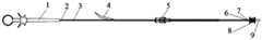
- Figure 1is a schematic diagram of the use of a head-end encircling clamping and conveying system
- Figure 2is a schematic diagram of a push handle on a head-end encircling clamping and conveying system
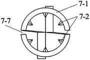
- Figure 3is a left view of the surrounding jaws
- Figure 4is a perspective view of the surrounding jaws
- Figure 5is a top view of the surrounding jaws
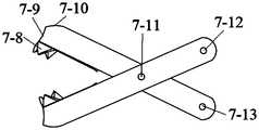
- Figure 6is a schematic diagram of the structure of alligator tooth jaws
- Figure 7is a left side view of Figure 6;
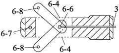
- Figure 8is a schematic diagram of the structure of the connecting tendon
- Figure 9is a schematic diagram of the internal structure of the connecting tendon
- Fig. 10is a structural schematic diagram of a head-end encircling clamping and conveying system.
- This applicationis a head-end embracing clamping and conveying system, as shown in Figure 1 and Figure 10, which includes a jaw part and a push part.
- the push partincludes a push handle 1, a push steel cable 2, a mandrel 3, and an adjustment line , Pull wire loader 5, connecting tendon 6, one end of the push handle 1 and one end of the push wire 2 are fixedly connected, and the outer side of the push wire 2 is provided with a pull wire loader 5 for pushing the push wire 2 into the sheath.
- the handle 1is internally connected to one end of the mandrel 3, and the other end of the mandrel 3 penetrates the inside of the pusher cable 2 and is connected to the connecting tendon 6, which is connected to the jaw part 7 for clamping and releasing the occluder.
- the other end of the mandrel 3is connected to the two connecting legs of the connecting tendon 6 through the first rotating shaft 6-6.
- the two connecting legsare respectively connected by the second rotating shaft 6-8, the other end of the pusher cable 2 is fixedly connected with one end of the connecting tendon 6, and the other end of the connecting tendon 6 and the jaw part 7 pass through the third rotating shaft 6- 7Connect.
- An adjustment wireis also arranged in the pull wire loader 5, and the adjustment wire is arranged on the outer side of the pushing steel cable 2.
- the adjustment wireWhen the adjustment wire is used, the adjustment wire is matched with the jaw part 7 to adjust the position of the degradable occluder 8 or withdraw the degradable occluder 8 as required; the adjustment wire connected to the degradable occluder 8 is loosened One end separates the adjustment line from the degradable occluder 8. The two ends of the adjustment wire are the other end 9 of the adjustment wire and one end 4 of the adjustment wire.
- the other end 9 of the adjustment wireis fixed on the push handle 1; when the push wire 2 is set in the sheath through the pull wire loader 5, one end of the adjustment wire 4 Enter the sheath through the pull wire loader 5 and pass through the jaw part 7 to connect to the degradable occluder 8, and then one end of the adjustment wire 4 passes through the jaw part 7, the sheath, and the pull wire loader 5 in turn, and returns to the push handle 1 place.
- the connecting tendon 6includes a connecting tendon body 6-5, a fifth connecting leg 6-2, and a sixth connecting leg 6-3.
- the connecting tendon body 6-5is provided with a mandrel for use. 3
- the two sides of the connecting tendon body 6-5are each provided with a long hole 6-4 communicating with the central hole, and one end of the fifth connecting leg 6-2 and the sixth connecting leg 6-3 are respectively provided
- one end of the fifth connecting leg 6-2 and the sixth connecting leg 6-3are respectively Pass through the long holes 6-4 on both sides of the connecting tendon body 6-5, and connect with the other end of the mandrel 3 in the central hole of the connecting tendon body 6-5 through the first rotating shaft 6-6, and connect the other end of the tendon 6
- a third shaft hole 6-1is provided, and the third shaft hole 6-1 of the connecting tendon 6 is connected to the jaw portion 7 through a
- the connecting tendon 6cooperates with the jaw part 7 to realize long-distance transmission movement, wherein the third shaft 6-7 passes through the third shaft hole 6-1 and the shaft hole on the jaw part 7, so that the two are connected as a whole .
- the fifth connecting leg 6-2 and the sixth connecting leg 6-3are connected to the two connecting legs of the jaw part 7, and the ends of the fifth connecting leg 6-2 and the sixth connecting leg 6-3 are connected to the spindle 3 and It is connected with the push handle 1 to control its movement at the remote end; to realize long-distance transmission, the push handle 1 can control its movement.
- the push handle 1When in use, the push handle 1 is connected with the push steel cable 2.
- the push steel cable 2can be pushed into the sheath through the cable loader 5.
- the two ends of the adjustment lineare one end of the adjustment line 4 and the other end of the adjustment line 9, and the other end of the adjustment line 9 is fixed on the push handle 1, and one end of the adjustment wire 4 enters the sheath through the pull wire loader 5 and is connected to the degradable occluder 8 through the jaw part 7, and then is loaded through the jaw part 7, sheath, and pull wire in turn
- the device 5returns to the push handle 1, that is, one end of the adjustment line 4 loops around and returns to the initial position.
- the adjustment wireonly passes through one side of the degradable occluder 8 and passes through the other side, so that the adjustment wire can pull the degradable occluder 8 to move together, and the adjustment wire is not fixed with the degradable occluder 8.
- the push handle 1is internally connected with a mandrel 3, which penetrates the entire push steel cable 2 and is connected with the connecting tendon 6, to control the movement of the jaw part 7, thereby clamping and releasing the occluder.
- the core shaft 3 inside the pushing steel cable 2is made of a special tough material, which can achieve good linkage and carry out long-distance transmission and radial rotation.
- the mandrel 3is connected with the jaw part 7 through the connecting tendon 6, which can realize long-distance locking and release.
- the adjustment wireis made of special materials, extremely thin and high-strength. It is located outside the push wire 2 and can be withdrawn after the treatment is completed; the adjustment wire is matched with the jaw part 7 to adjust the degradable seal as needed during the treatment.
- the position of the occluder 8has been changed from the disadvantage that it can only be delivered and cannot be adjusted, and the degradable occluder 8 can be withdrawn in an emergency, which greatly reduces the risk; it can better cope with the possible occurrences during the treatment process. All kinds of problems make the treatment process safer and more controllable.
- the push handle 1includes a bracelet 1-4, a push head 1-3, a push tendon 1-2, a screw buckle 1-5, a connecting rod 1-7, a push-pull block 1-6, and a bracelet 1-
- One end of 4is connected with one end of the connecting rod 1-7
- the other end of the connecting rod 1-7is provided with an open threaded head 1-1
- the middle of the connecting rod 1-7is provided with an open groove
- the connecting rod 1-7is covered with
- the push-pull sleeve 1-6that can slide on the connecting rod 1-7
- one end of the mandrel 3passes through the open threaded head 1-1 and is fixedly connected with the pusher 1-3
- the pusher 1-3is fixed on the pusher 1-2
- the pusher tendon 1-2is set in the open groove
- the outer side of the pusher tendon 1-2is connected with the push-pull sleeve 1-6 sleeved on the connecting rod 1-7
- the push head 1-3is connected to the mandrel 3 through the push tendon 1-2, which can control the front and back movement of the mandrel 3, thereby remotely controlling the opening and closing of the jaw part 7.
- the spiral buckle 1-5can be carried out after the jaw part 7 is closed. The distal end is locked so that the occluder is firmly fixed on the jaw part 7 of the delivery device.
- the hand ring 1-4is used to facilitate the hand-held push and pull during operation, so as to realize its movement.
- the jaw part 7is an enveloping jaw structure, including rivets 7-2 located on the inner wall of the semi-cylindrical jaw 7-1.
- rivets 7-2located on the inner wall of the semi-cylindrical jaw 7-1.
- the degradable occluder 8will move left and right and up and down.
- the two semi-cylindrical jaws 7-1are combined to form an encircling uniform tooth jaw.
- the inner wall of the encircling uniform tooth jawis cylindrical, which can fit well with the welding ball of the degradable occluder 8.
- the encircling structurehas a large contact area , It is not easy to pinch and damage the product;
- the integrated connecting piece 7-3is an integrated transition part connecting the first connecting leg 7-5, the second connecting leg 7-6 and the semi-cylindrical jaw 7-1.
- a first shaft hole 7-4is provided at the joint between the flexible connecting piece 7-3 and the connecting leg, and the third rotating shaft 6-7 passes through the first shaft hole 7-4 and the first shaft hole 7-4 on the two integrated connecting pieces 7-3.
- the other end of the connecting tendon 6is connected.
- the two parts of the integrated connecting piece 7-3are rotated through the first shaft hole 7-4 through the third rotating shaft 6-7, so that the jaws can be opened and closed.
- the inner wall of the uniform tooth jawsuses a quadrangular pyramid short barb structure, which can just slightly dent the polymer material without causing damage and increase the friction. , So that the degradable occluder 8 is firmer and not easy to shift and pull off during the transportation process.
- the first connecting leg 7-5, the second connecting leg 7-6 connected to the third rotating shaft 6-7 and the connecting leg of the connecting tendon 6are connected, and the push handle 1 can be used for long-distance transmission movement.
- the jaw part 7is an alligator tooth jaw structure, and the two jaws form an alligator tooth jaw.
- the alligator tooth jawconsists of two curved walls 7-10 and a curved wall.
- the crocodile teeth 7-8 on the 7-10are composed of crocodile teeth. It can damage the welding ball, and can smoothly transition with the increase of force to make the clamp tighter, and there is a certain margin to adapt to multiple welding balls of similar specifications.
- the crocodile teeth 7-8surround both sides of the top hole 7-9, and the curved wall 7-10 plays the role of fixing the end of the welding ball (the end and the net are connected by a boss), and the top hole 7-9 can clamp the end of the welding ball.
- the crocodile teeth 7-8act on the end of the welding ball to fix and prevent displacement.
- the third rotating shaft 6-7passes through the second shaft hole 7-11 in the middle of the two clamp rods and is connected to the other end of the connecting tendon 6, and the opening and closing movement is realized by the rotation of the third rotating shaft 6-7.
- the third connecting leg 7-12 and the fourth connecting leg 7-13are connected to the connecting leg of the connecting tendon 6 of the conveying device, and can perform long-distance transmission movement through the push handle 1.
- the crocodile teeth 7-8are at the head end, which can firmly fix the welding ball tail (the part that connects with the occluder net), and can be locked left and right to prevent product displacement, making it firmer and not easy to move during transportation. Pull off.
Landscapes
- Health & Medical Sciences (AREA)
- Surgery (AREA)
- Life Sciences & Earth Sciences (AREA)
- Medical Informatics (AREA)
- Animal Behavior & Ethology (AREA)
- Engineering & Computer Science (AREA)
- Biomedical Technology (AREA)
- Heart & Thoracic Surgery (AREA)
- Veterinary Medicine (AREA)
- Molecular Biology (AREA)
- Nuclear Medicine, Radiotherapy & Molecular Imaging (AREA)
- General Health & Medical Sciences (AREA)
- Public Health (AREA)
- Cardiology (AREA)
- Reproductive Health (AREA)
- Vascular Medicine (AREA)
- Surgical Instruments (AREA)
- Wire Processing (AREA)
- Ropes Or Cables (AREA)
Abstract
Description
Translated fromChinese本申请涉及一种头端环抱式夹紧输送系统,尤其涉及一种在先天性心脏病的介入治疗手术中用于输送可降解封堵器的辅助工具,属于临床医疗设备技术领域。The application relates to a head-end embracing clamping delivery system, in particular to an auxiliary tool for delivering a degradable occluder in an interventional treatment operation of congenital heart disease, which belongs to the technical field of clinical medical equipment.
随着技术的发展微创性治疗越来越广泛,微创性治疗较普通治疗有创口小出血少、恢复快、风险低等优点,得到了人们的广泛关注,也造福了广大的病患,尤其是老人和儿童。在治疗先天性结构心脏病时,常采用介入治疗的方法,在病变位置放置封堵器,从而达到很好的疗效。输送系统(即推送装置)作为一种精密医疗器械,在介入治疗手术中发挥着巨大作用。传统输送系统大都是与金属封堵器配合使用的,运用的多是螺纹连接或卡死连接,这些结构无法应用于可降解封堵器,或者会对可降解封堵器造成很大损伤。With the development of technology, minimally invasive treatments have become more and more widespread. Compared with ordinary treatments, minimally invasive treatments have the advantages of less invasive and small bleeding, faster recovery, and lower risk. They have attracted widespread attention and benefited a large number of patients. Especially the elderly and children. In the treatment of congenital structural heart disease, interventional therapy is often used to place an occluder at the lesion site to achieve a good effect. As a precision medical device, the delivery system (i.e. pusher) plays a huge role in interventional surgery. Traditional delivery systems are mostly used in conjunction with metal occluders, and most of them are threaded connections or stuck connections. These structures cannot be applied to degradable occluders, or can cause great damage to the degradable occluders.
发明内容Summary of the invention
本申请要解决的技术问题是:如何使得可降解封堵器具有与其配合使用的输送系统,避免对可降解封堵器造成损伤。The technical problem to be solved by this application is: how to make the degradable occluder have a delivery system that cooperates with it, so as to avoid damage to the degradable occluder.
为了解决上述技术问题,本申请的技术方案是提供了一种头端环抱式夹紧输送系统,其特征在于,包括钳口部分和推送部分,推送部分包括推送手柄、推送钢缆、芯轴、调整线、拉线装载器、连接腱,推送手柄的一端和推送钢缆的一端固定连接,推送钢缆的外侧设有用于将推送钢缆推送进鞘管的拉线装载器,推送手柄内部连接芯轴的一端,芯轴的另一端贯穿推送钢缆的内部并与连接腱相连,连接腱连接钳口部分,控制钳口部分的开合,从而夹持和释放封堵器。In order to solve the above technical problems, the technical solution of the present application is to provide a head-end embracing clamping and conveying system, which is characterized in that it includes a jaw part and a push part, and the push part includes a push handle, a push wire, a mandrel, Adjusting wire, pull wire loader, connecting tendon, one end of the push handle and one end of the push wire are fixedly connected, the outer side of the push wire is equipped with a pull wire loader for pushing the push wire into the sheath, and the inside of the push handle is connected to the mandrel One end of the mandrel and the other end of the mandrel penetrate the inside of the pusher cable and are connected to the connecting tendon, which connects to the jaw part, controls the opening and closing of the jaw part, thereby clamping and releasing the occluder.
优选地,所述的芯轴的另一端通过第一转动轴与连接腱的两个连接脚相连,连接腱的两个连接脚与用于夹持和释放封堵器的钳口部分的两个连接脚之间分别通过第二转动轴连接,推送钢缆的另一端与连接腱的一端固定连接,连接腱的另一端与钳口部分通过第三转动轴连接。Preferably, the other end of the mandrel is connected to the two connecting feet of the connecting tendon through the first rotating shaft, and the two connecting feet of the connecting tendon are connected to the two jaws used to clamp and release the occluder. The connecting legs are respectively connected by a second rotating shaft, the other end of the pushing steel cable is fixedly connected with one end of the connecting tendon, and the other end of the connecting tendon is connected with the jaw part by a third rotating shaft.
优选地,所述的拉线装载器内还设有调整线,调整线设于推送钢缆的外侧。Preferably, an adjustment wire is further provided in the pull wire loader, and the adjustment wire is provided on the outside of the push wire cable.
优选地,当所述的调整线使用时,调整线与钳口部分配合,根据需要调节可 降解封堵器的位置或回撤可降解封堵器;松开调整线上与可降解封堵器连接的一端并拉扯另一端,可以将线撤出鞘管,使得调整线与可降解封堵器分离。Preferably, when the adjustment wire is used, the adjustment wire is matched with the jaws to adjust the position of the degradable occluder or retract the degradable occluder as required; loosen the adjustment wire and the degradable occluder By connecting one end and pulling the other end, the wire can be withdrawn from the sheath, so that the adjustment wire is separated from the degradable occluder.
优选地,所述的调整线的两端分别为调整线另一端和调整线一端,调整线一端固定在推送手柄上;当推送钢缆通过拉线装载器设于鞘管内时,调整线一端通过拉线装载器进入鞘管并通过钳口部分与可降解封堵器相连接,随后调整线一端依次通过钳口部分、鞘管、拉线装载器,返回至推送手柄处。Preferably, the two ends of the adjustment wire are the other end of the adjustment wire and one end of the adjustment wire, and one end of the adjustment wire is fixed on the push handle; when the push wire is set in the sheath through the pull wire loader, one end of the adjustment wire passes through the pull wire The loader enters the sheath tube and is connected to the degradable occluder through the jaw part, and then one end of the adjustment wire passes through the jaw part, the sheath tube, and the pull wire loader in turn, and returns to the push handle.
优选地,所述的连接腱包括连接腱本体、第五连接脚、第六连接脚,连接腱本体内设有一个可供芯轴穿过的中心孔,连接腱本体的两侧各设有一个与中心孔相通的长孔,第五连接脚和第六连接脚的一端分别设于连接腱本体的两侧,且与钳口部分的两个连接脚通过第二转动轴连接,第五连接脚和第六连接脚的一端分别穿过连接腱本体两侧的长孔,且与连接腱本体中心孔内的芯轴另一端通过第一转动轴连接,连接腱的另一端设有第三轴孔,连接腱的第三轴孔通过第三转动轴与钳口部分连接。Preferably, the connecting tendon includes a connecting tendon body, a fifth connecting foot, and a sixth connecting foot. The connecting tendon body is provided with a central hole through which the mandrel can pass, and there is one on each side of the connecting tendon body. The long hole communicating with the central hole, one ends of the fifth connecting leg and the sixth connecting leg are respectively provided on both sides of the connecting tendon body, and are connected with the two connecting legs of the jaw part through the second rotating shaft, the fifth connecting leg One end of the sixth connecting leg and the sixth connecting leg respectively pass through the long holes on both sides of the connecting tendon body, and are connected to the other end of the mandrel in the central hole of the connecting tendon body through a first rotating shaft, and the other end of the connecting tendon is provided with a third shaft hole , The third shaft hole connecting the tendon is connected with the jaw part through the third rotating shaft.
优选地,所述的钳口部分包括两个钳杆,两个钳杆的中间通过第三转动轴活动连接,两个钳杆的一端各设有一个连接脚,两个钳杆一端的两个连接脚与连接腱的两个连接脚之间通过第二转动轴活动连接,两个钳杆的另一端各设有一个钳口;当两个钳杆一端的两个连接脚绕着第三转动轴相对转动时,两个钳杆另一端的两个钳口也相对转动,从而夹住可降解封堵器;当两个钳杆一端的两个连接脚绕着第三转动轴相背转动时,两个钳杆另一端的两个钳口也相背转动,从而释放可降解封堵器。Preferably, the jaw part includes two pliers rods, the middle of the two pliers rods is movably connected by a third rotating shaft, one end of the two pliers rods is each provided with a connecting leg, and the two pliers rods have two The connecting feet and the two connecting feet of the connecting tendon are movably connected by the second rotating shaft, and the other ends of the two pliers rods are each provided with a jaw; when the two connecting feet at one end of the two pliers rods rotate around the third When the shafts rotate relative to each other, the two jaws at the other end of the two clamp rods also rotate relative to each other, thereby clamping the degradable occluder; when the two connecting feet at one end of the two clamp rods rotate opposite to each other around the third rotation axis , The two jaws at the other end of the two pliers rods also rotate opposite to each other, thereby releasing the degradable occluder.
优选地,所述的钳口部分为环抱式钳口结构,两个钳口为两个半圆柱钳口,组合形成环抱均齿钳口,环抱均齿钳口的内壁呈能与可降解封堵器熔接球配合的圆柱形结构,每个半圆柱钳口的内壁上均布有多个防止可降解封堵器出现左右上下移动的铆钉;钳杆包括半圆柱钳口、一体式连接件、连接脚,一体式连接件为钳杆上的连接脚与半圆柱钳口之间相连的一体式过渡部分,一体式连接件和钳杆上连接脚的连接处设有第一轴孔,第三转动轴穿过两个一体式连接件上的第一轴孔与连接腱的另一端连接;两个半圆柱钳口之间设有预留缝隙。Preferably, the jaw part is an enclosing jaw structure, and the two jaws are two semi-cylindrical jaws, which are combined to form an encircling uniform tooth jaw, and the inner wall of the encircling uniform tooth jaw is capable of and degradable sealing The inner wall of each semi-cylindrical jaw is evenly distributed with a number of rivets to prevent the degradable occluder from moving left and right up and down; the clamp rod includes a semi-cylindrical jaw, an integrated connector, and a Feet, the integral connecting piece is an integral transition part between the connecting leg on the pliers rod and the semi-cylindrical jaws. The joint between the integral connecting piece and the connecting leg on the pliers rod is provided with a first shaft hole, and the third rotation The shaft passes through the first shaft hole on the two integrated connecting pieces and is connected to the other end of the connecting tendon; a reserved gap is provided between the two semi-cylindrical jaws.
优选地,所述的钳口部分为鳄鱼齿钳口结构,两个钳口形成鳄鱼齿钳口,鳄鱼齿钳口由两个曲面壁以及曲面壁上的鳄鱼齿组成,鳄鱼齿钳口的头端为呈圆形 开口的顶端孔,顶端孔与曲面壁平滑过渡,鳄鱼齿环绕在顶端孔两边,两个钳杆的中间均设有第二轴孔,第三转动轴穿过两个钳杆中间的第二轴孔与连接腱的另一端连接。Preferably, the jaw part is an alligator tooth jaw structure, the two jaws form an alligator tooth jaw, the alligator tooth jaw is composed of two curved walls and the alligator teeth on the curved wall, the head of the alligator tooth jaw The end is a top hole with a circular opening. The top hole and the curved wall are smoothly transitioned. Alligator teeth surround both sides of the top hole. The middle of the two pliers rods is provided with a second shaft hole, and the third rotation shaft passes through the two pliers rods. The second shaft hole in the middle is connected to the other end of the connecting tendon.
优选地,所述的推送手柄包括手环、推送头、推送腱、螺旋扣、连接杆、推拉块,手环的一端与连接杆的一端连接,连接杆的另一端设有开口螺纹头,连接杆的中间设有开口槽,连接杆上套有可以在连接杆上滑动的推拉套,芯轴的一端穿过开口螺纹头与推送头固定连接,推送头固定在推送腱上,推送腱设于开口槽内,推送腱外侧与套在连接杆上的推拉套连接,开口螺纹头的外侧套有使得开口螺纹头卡紧芯轴的螺旋扣,推送钢缆的一端与开口螺纹头连接。Preferably, the push handle includes a hand ring, a push head, a push tendon, a screw buckle, a connecting rod, and a push-pull block. One end of the bracelet is connected with one end of the connecting rod, and the other end of the connecting rod is provided with an open threaded head, There is an open slot in the middle of the rod, and the connecting rod is covered with a push-pull sleeve that can slide on the connecting rod. In the open groove, the outer side of the pusher tendon is connected with the push-pull sleeve sleeved on the connecting rod, the outer side of the open threaded head is sheathed with a screw buckle that makes the open threaded head clamp the mandrel, and one end of the pusher cable is connected with the open threaded head.
本申请提供了一种头端环抱式夹紧输送系统,配合可降解封堵器使用,可以实现可降解封堵器的微创介入治疗,完成可降解封堵器的夹持、装载、输送、锁紧、释放、回收等功能。并且具有较好的过鞘能力,对可降解封堵器有良好的夹持力和稳固性。其牢固性高,易于推送、释放及回收,过鞘能力强,与产品配合度高。推送钢缆内部配合芯轴,具有良好的联动性,可以长距离传输径向旋转,适应了不同病人的血管及其走向。控制手柄、推送钢缆、连接腱和钳口依次相连接实现长距离控制;另外配有调整线与钳口部分配合,可以实现封堵器在病变位置的调节和回收。通过使用本申请的输送系统,极大地提高了治疗的灵活性和安全性,保证了病人的治疗效果。This application provides a head-end encircling clamping and conveying system, which can be used in conjunction with a degradable occluder to realize minimally invasive interventional treatment of the degradable occluder, and complete the clamping, loading, conveying, and delivery of the degradable occluder. Locking, releasing, recycling and other functions. And it has good sheathing ability, and has good clamping force and stability to the degradable occluder. It has high firmness, is easy to push, release and recycle, has strong sheathing ability, and has a high degree of coordination with the product. The inside of the push wire cable is matched with the mandrel, which has good linkage, can transmit radial rotation for a long distance, and adapt to the blood vessels and directions of different patients. The control handle, the push cable, the connecting tendon and the jaw are connected in sequence to realize long-distance control; in addition, an adjustment wire is equipped with the jaw part to cooperate to realize the adjustment and recovery of the occluder at the lesion position. By using the delivery system of the present application, the flexibility and safety of treatment are greatly improved, and the treatment effect of the patient is ensured.
其中,钳口部分有两种设计:Among them, the jaw part has two designs:
(1)第一种,环抱均齿钳口(1) The first type, encircling the jaws of uniform teeth
环抱均齿钳口壁呈圆柱形,此部分能很好的和可降解封堵器的熔接球配合,环抱式结构接触面积大,不容易夹伤和损坏产品;钳口部分留有缝隙,可配合多个相近规格的熔接球;且可降解高分子材料有一定弹性,钳口部分使用四棱锥短倒刺结构可以刚好使高分子材料轻微凹陷且不造成损伤,增加了摩擦力,使可降解封堵器在输送过程中更牢固且不容易移位和拉脱。The wall of the jaws of the surrounding uniform teeth is cylindrical. This part can fit well with the welding ball of the degradable occluder. The surrounding structure has a large contact area and is not easy to pinch and damage the product; there are gaps in the jaws. Cooperate with multiple welding balls of similar specifications; and the biodegradable polymer material has a certain degree of flexibility. The use of a quadrangular pyramid short barb structure in the jaw part can just slightly dent the polymer material without causing damage, increasing friction and making it degradable The occluder is firmer and not easy to move and pull off during the transportation process.
(2)第二种,鳄鱼齿钳口,(2) The second type, alligator tooth jaws,
鳄鱼齿钳口头端呈圆形开口,并有平滑过渡的曲面内壁,使其不容易刮伤熔接球,并能随着力的增大平滑过渡使其夹的更紧,且有一定的余量能适应多个相近规格的熔接球。鳄鱼齿在头端,可以牢牢地固定熔接球尾部(与封堵器网交接 部分),并且可以左右锁紧防止产品位移,使其在输送过程中更牢固且不容易移位和拉脱。The mouth end of the alligator tooth pliers has a circular opening and a smooth transition of the curved inner wall, which makes it not easy to scratch the welding ball, and can smoothly transition with the increase of force to make the clamp tighter, and there is a certain margin of energy Adapt to multiple welding balls of similar specifications. The crocodile teeth are at the head end, which can firmly fix the fusion ball tail (the part that is connected to the occluder net), and can be locked left and right to prevent product displacement, making it firmer and not easy to move and pull off during transportation.
图1为一种头端环抱式夹紧输送系统的使用示意图;Figure 1 is a schematic diagram of the use of a head-end encircling clamping and conveying system;
图2为一种头端环抱式夹紧输送系统上推送手柄处的示意图;Figure 2 is a schematic diagram of a push handle on a head-end encircling clamping and conveying system;
图3为环抱式钳口的左视图;Figure 3 is a left view of the surrounding jaws;
图4为环抱式钳口的立体图;Figure 4 is a perspective view of the surrounding jaws;
图5为环抱式钳口的俯视图;Figure 5 is a top view of the surrounding jaws;
图6为鳄鱼齿钳口的结构示意图;Figure 6 is a schematic diagram of the structure of alligator tooth jaws;
图7为图6的左视图;Figure 7 is a left side view of Figure 6;
图8为连接腱的结构示意图;Figure 8 is a schematic diagram of the structure of the connecting tendon;
图9为连接腱的内部结构示意图;Figure 9 is a schematic diagram of the internal structure of the connecting tendon;
图10为一种头端环抱式夹紧输送系统的结构示意图。Fig. 10 is a structural schematic diagram of a head-end encircling clamping and conveying system.
为使本申请更明显易懂,兹以优选实施例,并配合附图作详细说明如下。In order to make this application more comprehensible, a detailed description is given below with preferred embodiments and accompanying drawings.
实施例1Example 1
本申请为一种头端环抱式夹紧输送系统,如图1、图10所示,其包括钳口部分和推送部分,推送部分包括推送手柄1、推送钢缆2、芯轴3、调整线、拉线装载器5、连接腱6,推送手柄1的一端和推送钢缆2的一端固定连接,推送钢缆2的外侧设有用于将推送钢缆2推送进鞘管的拉线装载器5,推送手柄1内部连接芯轴3的一端,芯轴3的另一端贯穿推送钢缆2的内部并与连接腱6相连,连接腱6与用于夹持和释放封堵器的钳口部分7连接。芯轴3的另一端通过第一转动轴6-6与连接腱6的两个连接脚相连,连接腱6的两个连接脚与用于夹持和释放封堵器的钳口部分7的两个连接脚之间分别通过第二转动轴6-8连接,推送钢缆2的另一端与连接腱6的一端固定连接,连接腱6的另一端与钳口部分7通过第三转动轴6-7连接。拉线装载器5内还设有调整线,调整线设于推送钢缆2的外侧。当调整线使用时,调整线与钳口部分7配合,根据需要调节可降解封堵器8的位置或回撤可降解封堵器8;与可降解封堵器8连接的调整线通过松开一端,使得调整线与可降解封堵器8分离。调整线的两端分别为调整线另一端9和 调整线一端4,调整线另一端9固定在推送手柄1上;当推送钢缆2通过拉线装载器5设于鞘管内时,调整线一端4通过拉线装载器5进入鞘管并穿过钳口部分7与可降解封堵器8相连接,随后调整线一端4依次穿过钳口部分7、鞘管、拉线装载器5,返回至推送手柄1处。This application is a head-end embracing clamping and conveying system, as shown in Figure 1 and Figure 10, which includes a jaw part and a push part. The push part includes a
如图8、图9所示,连接腱6包括连接腱本体6-5、第五连接脚6-2、第六连接脚6-3,连接腱本体6-5内设有一个可供芯轴3穿过的中心孔,连接腱本体6-5的两侧各设有一个与中心孔相通的长孔6-4,第五连接脚6-2和第六连接脚6-3的一端分别设于连接腱本体6-5的两侧,且与钳口部分7的两个连接脚通过第二转动轴6-8连接,第五连接脚6-2和第六连接脚6-3的一端分别穿过连接腱本体6-5两侧的长孔6-4,且与连接腱本体6-5中心孔内的芯轴3另一端通过第一转动轴6-6连接,连接腱6的另一端设有第三轴孔6-1,连接腱6的第三轴孔6-1通过第三转动轴6-7与钳口部分7连接。As shown in Figures 8 and 9, the connecting
连接腱6与钳口部分7配合实现长距离传输运动,其中,通过第三转动轴6-7穿过第三轴孔6-1与钳口部分7上的轴孔,使得两者相连成为一体。第五连接脚6-2、第六连接脚6-3与钳口部分7的两个连接脚相连,第五连接脚6-2、第六连接脚6-3的末端与芯轴3相连并与推送手柄1相连,从而在远端控制其运动;以此实现长距离传输,推送手柄1端可控制其运动。The connecting
使用时,推送手柄1和推送钢缆2连接,推送钢缆2可以通过拉线装载器5推送进鞘管,调整线的两端分别为调整线一端4和调整线另一端9,调整线另一端9固定在推送手柄1上,调整线一端4通过拉线装载器5进入鞘管并通过钳口部分7与可降解封堵器8相连接,随后依次再通过钳口部分7、鞘管、拉线装载器5,返回至推送手柄1处,即调整线一端4环绕一圈后回到初始位置。其中,调整线只是从可降解封堵器8一侧穿过,另一侧穿出,使得调整线可以拉动可降解封堵器8一起移动,调整线不与可降解封堵器8固定。推送手柄1内部连接芯轴3,芯轴3贯穿整个推送钢缆2内部,并与连接腱6相连,控制钳口部分7运动,从而夹持和释放封堵器。When in use, the push handle 1 is connected with the
推送钢缆2内部的芯轴3由特殊韧性材料制成,可实现良好的联动性,进行长距离传输径向旋转。芯轴3通过连接腱6与钳口部分7连接,能实现长距离锁紧和释放。调整线由特殊材料制成,极细且有高强度,位于推送钢缆2外侧,治 疗完成后即可撤出;调整线与钳口部分7配合,能在治疗过程中根据需要调节可降解封堵器8的位置,一改以往只能输送不能调整的弊端,并且能在紧急情况下将可降解封堵器8回撤,极大的减少了风险;能更好的应对治疗过程中可能出现的的种种问题,使治疗过程更加安全可控。The
如图2所示,推送手柄1包括手环1-4、推送头1-3、推送腱1-2、螺旋扣1-5、连接杆1-7、推拉块1-6,手环1-4的一端与连接杆1-7的一端连接,连接杆1-7的另一端设有开口螺纹头1-1,连接杆1-7的中间设有开口槽,连接杆1-7上套有可以在连接杆1-7上滑动的推拉套1-6,芯轴3的一端穿过开口螺纹头1-1与推送头1-3固定连接,推送头1-3固定在推送腱1-2上,推送腱1-2设于开口槽内,推送腱1-2外侧与套在连接杆1-7上的推拉套1-6连接,开口螺纹头1-1的外侧套有使得开口螺纹头1-1卡紧芯轴3的螺旋扣1-5,推送钢缆2的一端与开口螺纹头1-1连接。As shown in Figure 2, the push handle 1 includes a bracelet 1-4, a push head 1-3, a push tendon 1-2, a screw buckle 1-5, a connecting rod 1-7, a push-pull block 1-6, and a bracelet 1- One end of 4 is connected with one end of the connecting rod 1-7, the other end of the connecting rod 1-7 is provided with an open threaded head 1-1, the middle of the connecting rod 1-7 is provided with an open groove, and the connecting rod 1-7 is covered with The push-pull sleeve 1-6 that can slide on the connecting rod 1-7, one end of the mandrel 3 passes through the open threaded head 1-1 and is fixedly connected with the pusher 1-3, and the pusher 1-3 is fixed on the pusher 1-2 On the upper side, the pusher tendon 1-2 is set in the open groove, the outer side of the pusher tendon 1-2 is connected with the push-pull sleeve 1-6 sleeved on the connecting rod 1-7, and the outer side of the open threaded head 1-1 is covered with an open threaded head 1-1 The screw buckle 1-5 of the mandrel 3 is clamped, and one end of the pushing steel cable 2 is connected with the open threaded head 1-1.
推送头1-3通过推送腱1-2与芯轴3相连,可以控制芯轴3前后运动,从而远端控制钳口部分7开合,螺旋扣1-5可以在钳口部分7闭合后进行远端锁紧,从而将封堵器牢固的固定在输送装置钳口部分7上。手环1-4用于在操作过程中方便手持推拉,从而实现其运动。The push head 1-3 is connected to the
如图3-图5所示,钳口部分7为环抱式钳口结构,包括位于半圆柱钳口7-1的内壁上的铆钉7-2,共18个,起固定防滑作用,能够限制其在使用过程中,可降解封堵器8会出现的左右和上下移动。两个半圆柱钳口7-1组合形成环抱均齿钳口,环抱均齿钳口的内壁呈圆柱形,能很好的和可降解封堵器8的熔接球配合,环抱式结构接触面积大,不容易夹伤和损坏产品;一体式连接件7-3为第一连接脚7-5、第二连接脚7-6与半圆柱钳口7-1之间相连的一体式过渡部分,一体式连接件7-3和连接脚的连接处设有第一轴孔7-4,第三转动轴6-7穿过两个一体式连接件7-3上的第一轴孔7-4与连接腱6的另一端连接。一体式连接件7-3的两个部分通过第三转动轴6-7穿过第一轴孔7-4实现转动,从而使钳口达到开合的目的。两个半圆柱钳口7-1之间设有预留缝隙7-7,让钳口能够夹紧产品(熔接球),并且能适应一定尺寸范围的产品(熔接球)规格型号,即可配合多个相近规格的熔接球;且可降解高分子材料有一定弹性,环抱均齿钳口的内壁使用四棱锥短倒刺结构,可以刚好使高分子材料轻微凹陷且不造成损伤,增加了摩擦力, 使可降解封堵器8在输送过程中更牢固且不容易移位和拉脱。与第三转动轴6-7连接的第一连接脚7-5、第二连接脚7-6和连接腱6的连接脚相连,能通过推送手柄1进行长距离传输运动。As shown in Figure 3-Figure 5, the
实施例2Example 2
本实施例中,如图6、图7所示,钳口部分7为鳄鱼齿钳口结构,两个钳口形成鳄鱼齿钳口,鳄鱼齿钳口由两个曲面壁7-10以及曲面壁7-10上的鳄鱼齿7-8组成,鳄鱼齿钳口的头端为呈圆形开口的顶端孔7-9,顶端孔7-9与曲面壁7-10平滑过渡,使其不容易刮伤熔接球,并能随着力的增大平滑过渡使其夹的更紧,且有一定的余量能适应多个相近规格的熔接球。鳄鱼齿7-8环绕在顶端孔7-9两边,曲面壁7-10起到熔接球尾端(尾端与网连接处有凸台)固定作用,顶端孔7-9可将熔接球尾部卡在孔中,鳄鱼齿7-8作用在熔接球尾端,起到固定和防止位移的作用。第三转动轴6-7穿过两个钳杆中间的第二轴孔7-11与连接腱6的另一端连接,通过第三转动轴6-7的转动,实现开合运动。第三连接脚7-12、第四连接脚7-13与输送装置连接腱6的连接脚相连,能通过推送手柄1进行长距离传输运动。鳄鱼齿7-8在头端,可以牢牢地固定熔接球尾部(与封堵器网交接部分),并且可以左右锁紧防止产品位移,使其在输送过程中更牢固且不容易移位和拉脱。In this embodiment, as shown in Figures 6 and 7, the
其他与实施例1相同。Others are the same as in Example 1.
Claims (10)
Translated fromChinesePriority Applications (3)
| Application Number | Priority Date | Filing Date | Title |
|---|---|---|---|
| EP21825366.4AEP4005501B1 (en) | 2020-06-16 | 2021-04-23 | Head end enveloping-type clamping and conveying system |
| ES21825366TES2979309T3 (en) | 2020-06-16 | 2021-04-23 | Wrap-around type clamping and transport system at the end of the head |
| PL21825366.4TPL4005501T3 (en) | 2020-06-16 | 2021-04-23 | Head end enveloping-type clamping and conveying system |
Applications Claiming Priority (2)
| Application Number | Priority Date | Filing Date | Title |
|---|---|---|---|
| CN202010546781.X | 2020-06-16 | ||
| CN202010546781.XACN111658026B (en) | 2020-06-16 | 2020-06-16 | Head end encircling type clamping conveying system |
Publications (1)
| Publication Number | Publication Date |
|---|---|
| WO2021253980A1true WO2021253980A1 (en) | 2021-12-23 |
Family
ID=72387831
Family Applications (1)
| Application Number | Title | Priority Date | Filing Date |
|---|---|---|---|
| PCT/CN2021/089249CeasedWO2021253980A1 (en) | 2020-06-16 | 2021-04-23 | Head end enveloping-type clamping and conveying system |
Country Status (5)
| Country | Link |
|---|---|
| EP (1) | EP4005501B1 (en) |
| CN (1) | CN111658026B (en) |
| ES (1) | ES2979309T3 (en) |
| PL (1) | PL4005501T3 (en) |
| WO (1) | WO2021253980A1 (en) |
Families Citing this family (3)
| Publication number | Priority date | Publication date | Assignee | Title |
|---|---|---|---|---|
| CN111658026B (en)* | 2020-06-16 | 2024-11-29 | 上海形状记忆合金材料有限公司 | Head end encircling type clamping conveying system |
| CN113413243A (en)* | 2021-06-22 | 2021-09-21 | 上海形状记忆合金材料有限公司 | Can lock not have biological atrium diverging device of riveting |
| CN114027915B (en)* | 2021-08-26 | 2023-09-08 | 上海形状记忆合金材料有限公司 | Cardiovascular plugging device conveying device with molding line protection |
Citations (8)
| Publication number | Priority date | Publication date | Assignee | Title |
|---|---|---|---|---|
| US20070112381A1 (en)* | 2005-11-14 | 2007-05-17 | Jen.Meditec Gmbh | Occlusion device and surgical instrument and method for its implantation/explantation |
| CN201578327U (en)* | 2009-12-30 | 2010-09-15 | 杭州康基医疗器械有限公司 | Forward-viewing minimal invasive non-invasive small grasping forceps |
| CN102481147A (en)* | 2009-05-06 | 2012-05-30 | 奥特鲁泰克控股有限公司 | Implant, medical implant and method for delivering medical implant |
| CN102802538A (en)* | 2009-06-22 | 2012-11-28 | 戈尔企业控股股份有限公司 | Seals and delivery systems |
| CN103690202A (en)* | 2013-12-30 | 2014-04-02 | 先健科技(深圳)有限公司 | Implant conveying device and implantable medical device |
| CN109498074A (en)* | 2019-01-04 | 2019-03-22 | 上海形状记忆合金材料有限公司 | Method Wholly-degradable plugging device dedicated driving means and its connect with plugging device |
| CN111658026A (en)* | 2020-06-16 | 2020-09-15 | 上海形状记忆合金材料有限公司 | Head end encircling type clamping conveying system |
| CN212939808U (en)* | 2020-06-16 | 2021-04-13 | 上海形状记忆合金材料有限公司 | A head-end embracing clamping conveying system |
Family Cites Families (4)
| Publication number | Priority date | Publication date | Assignee | Title |
|---|---|---|---|---|
| DE29500381U1 (en)* | 1994-08-24 | 1995-07-20 | Schneidt, Bernhard, Ing.(grad.), 63571 Gelnhausen | Device for closing a duct, in particular the ductus arteriosus |
| CN201905938U (en)* | 2010-11-30 | 2011-07-27 | 上海长海医院 | Conveying and recovery device for transcatheter minimally invasive intervention operation |
| CN106618664B (en)* | 2016-12-06 | 2023-04-14 | 上海心玮医疗科技股份有限公司 | Left auricle occluder conveying system |
| CN110876633B (en)* | 2019-12-03 | 2024-06-14 | 江苏博朗森思医疗器械有限公司 | Special conveyer of degradable plugging device |
- 2020
- 2020-06-16CNCN202010546781.XApatent/CN111658026B/enactiveActive
- 2021
- 2021-04-23ESES21825366Tpatent/ES2979309T3/enactiveActive
- 2021-04-23WOPCT/CN2021/089249patent/WO2021253980A1/ennot_activeCeased
- 2021-04-23PLPL21825366.4Tpatent/PL4005501T3/enunknown
- 2021-04-23EPEP21825366.4Apatent/EP4005501B1/enactiveActive
Patent Citations (8)
| Publication number | Priority date | Publication date | Assignee | Title |
|---|---|---|---|---|
| US20070112381A1 (en)* | 2005-11-14 | 2007-05-17 | Jen.Meditec Gmbh | Occlusion device and surgical instrument and method for its implantation/explantation |
| CN102481147A (en)* | 2009-05-06 | 2012-05-30 | 奥特鲁泰克控股有限公司 | Implant, medical implant and method for delivering medical implant |
| CN102802538A (en)* | 2009-06-22 | 2012-11-28 | 戈尔企业控股股份有限公司 | Seals and delivery systems |
| CN201578327U (en)* | 2009-12-30 | 2010-09-15 | 杭州康基医疗器械有限公司 | Forward-viewing minimal invasive non-invasive small grasping forceps |
| CN103690202A (en)* | 2013-12-30 | 2014-04-02 | 先健科技(深圳)有限公司 | Implant conveying device and implantable medical device |
| CN109498074A (en)* | 2019-01-04 | 2019-03-22 | 上海形状记忆合金材料有限公司 | Method Wholly-degradable plugging device dedicated driving means and its connect with plugging device |
| CN111658026A (en)* | 2020-06-16 | 2020-09-15 | 上海形状记忆合金材料有限公司 | Head end encircling type clamping conveying system |
| CN212939808U (en)* | 2020-06-16 | 2021-04-13 | 上海形状记忆合金材料有限公司 | A head-end embracing clamping conveying system |
Non-Patent Citations (1)
| Title |
|---|
| See also references ofEP4005501A4* |
Also Published As
| Publication number | Publication date |
|---|---|
| CN111658026A (en) | 2020-09-15 |
| ES2979309T3 (en) | 2024-09-25 |
| CN111658026B (en) | 2024-11-29 |
| PL4005501T3 (en) | 2024-06-10 |
| EP4005501A4 (en) | 2022-11-16 |
| EP4005501B1 (en) | 2024-01-24 |
| EP4005501A1 (en) | 2022-06-01 |
Similar Documents
| Publication | Publication Date | Title |
|---|---|---|
| WO2021253980A1 (en) | Head end enveloping-type clamping and conveying system | |
| US20230107869A1 (en) | Implant, Medical Implant, And Method For Delivery Of A Medical Implant | |
| CN106890012B (en) | Handle for delivery catheter and method of use | |
| JP6181235B2 (en) | Medical device for treating foreign matter | |
| WO2016150261A1 (en) | Catheter which locks pads and cuts sutures | |
| JP2016179185A (en) | Repair of tricuspid valve using tension | |
| WO2007054014A1 (en) | Delivery device for delivering a self-expanding stent | |
| CN114431917B (en) | Hemostatic clamp | |
| WO2017066987A1 (en) | Ligation device | |
| WO2014044212A1 (en) | Implant conveying system | |
| JP2005505337A (en) | Scope Endoscopic hemostatic clip device | |
| JP2002520125A (en) | Mitral and cuspid valve treatment | |
| EP3834782A1 (en) | Delivery apparatus | |
| WO2022121527A1 (en) | Valve clip delivery device | |
| CN111568605A (en) | Prosthetic Components and Prosthetic Component Implants | |
| US20250025300A1 (en) | Ligating devices and methods for heart valve repair | |
| CN111374800A (en) | A valve ring retraction system | |
| CN212939808U (en) | A head-end embracing clamping conveying system | |
| CN107997803A (en) | A kind of tissue folder that can continuously discharge clamping | |
| CN209916301U (en) | Single-window guided valve ring-contracting system | |
| AU2019412317A1 (en) | Delivery catheter and delivery device for artificial valve | |
| CN113081423A (en) | Stent delivery and release device and stent delivery and release system | |
| CN110916851B (en) | A universal heart valve interventional angioplasty system | |
| CN212490282U (en) | Stent delivery and release device and stent delivery and release system | |
| CN120392374A (en) | Valve clamping system with linkage control |
Legal Events
| Date | Code | Title | Description |
|---|---|---|---|
| 121 | Ep: the epo has been informed by wipo that ep was designated in this application | Ref document number:21825366 Country of ref document:EP Kind code of ref document:A1 | |
| ENP | Entry into the national phase | Ref document number:2021825366 Country of ref document:EP Effective date:20220225 | |
| NENP | Non-entry into the national phase | Ref country code:DE |