WO2021253499A1 - Capacitive micro-electro-mechanical system microphone, microphone unit, and electronic device - Google Patents
Capacitive micro-electro-mechanical system microphone, microphone unit, and electronic deviceDownload PDFInfo
- Publication number
- WO2021253499A1 WO2021253499A1PCT/CN2020/099425CN2020099425WWO2021253499A1WO 2021253499 A1WO2021253499 A1WO 2021253499A1CN 2020099425 WCN2020099425 WCN 2020099425WWO 2021253499 A1WO2021253499 A1WO 2021253499A1
- Authority
- WO
- WIPO (PCT)
- Prior art keywords
- diaphragm
- back plate
- capacitive
- microphone
- support
- Prior art date
- Legal status (The legal status is an assumption and is not a legal conclusion. Google has not performed a legal analysis and makes no representation as to the accuracy of the status listed.)
- Ceased
Links
Images


Classifications
- H—ELECTRICITY
- H04—ELECTRIC COMMUNICATION TECHNIQUE
- H04R—LOUDSPEAKERS, MICROPHONES, GRAMOPHONE PICK-UPS OR LIKE ACOUSTIC ELECTROMECHANICAL TRANSDUCERS; DEAF-AID SETS; PUBLIC ADDRESS SYSTEMS
- H04R19/00—Electrostatic transducers
- H04R19/005—Electrostatic transducers using semiconductor materials
- H—ELECTRICITY
- H04—ELECTRIC COMMUNICATION TECHNIQUE
- H04R—LOUDSPEAKERS, MICROPHONES, GRAMOPHONE PICK-UPS OR LIKE ACOUSTIC ELECTROMECHANICAL TRANSDUCERS; DEAF-AID SETS; PUBLIC ADDRESS SYSTEMS
- H04R19/00—Electrostatic transducers
- H04R19/04—Microphones
- H—ELECTRICITY
- H04—ELECTRIC COMMUNICATION TECHNIQUE
- H04R—LOUDSPEAKERS, MICROPHONES, GRAMOPHONE PICK-UPS OR LIKE ACOUSTIC ELECTROMECHANICAL TRANSDUCERS; DEAF-AID SETS; PUBLIC ADDRESS SYSTEMS
- H04R1/00—Details of transducers, loudspeakers or microphones
- H04R1/02—Casings; Cabinets ; Supports therefor; Mountings therein
- H04R1/04—Structural association of microphone with electric circuitry therefor
- H—ELECTRICITY
- H04—ELECTRIC COMMUNICATION TECHNIQUE
- H04R—LOUDSPEAKERS, MICROPHONES, GRAMOPHONE PICK-UPS OR LIKE ACOUSTIC ELECTROMECHANICAL TRANSDUCERS; DEAF-AID SETS; PUBLIC ADDRESS SYSTEMS
- H04R7/00—Diaphragms for electromechanical transducers; Cones
- H04R7/02—Diaphragms for electromechanical transducers; Cones characterised by the construction
- H04R7/12—Non-planar diaphragms or cones
- H04R7/122—Non-planar diaphragms or cones comprising a plurality of sections or layers
- H04R7/125—Non-planar diaphragms or cones comprising a plurality of sections or layers comprising a plurality of superposed layers in contact
- H—ELECTRICITY
- H04—ELECTRIC COMMUNICATION TECHNIQUE
- H04R—LOUDSPEAKERS, MICROPHONES, GRAMOPHONE PICK-UPS OR LIKE ACOUSTIC ELECTROMECHANICAL TRANSDUCERS; DEAF-AID SETS; PUBLIC ADDRESS SYSTEMS
- H04R7/00—Diaphragms for electromechanical transducers; Cones
- H04R7/16—Mounting or tensioning of diaphragms or cones
- H—ELECTRICITY
- H04—ELECTRIC COMMUNICATION TECHNIQUE
- H04R—LOUDSPEAKERS, MICROPHONES, GRAMOPHONE PICK-UPS OR LIKE ACOUSTIC ELECTROMECHANICAL TRANSDUCERS; DEAF-AID SETS; PUBLIC ADDRESS SYSTEMS
- H04R7/00—Diaphragms for electromechanical transducers; Cones
- H04R7/26—Damping by means acting directly on free portion of diaphragm or cone
- H—ELECTRICITY
- H04—ELECTRIC COMMUNICATION TECHNIQUE
- H04R—LOUDSPEAKERS, MICROPHONES, GRAMOPHONE PICK-UPS OR LIKE ACOUSTIC ELECTROMECHANICAL TRANSDUCERS; DEAF-AID SETS; PUBLIC ADDRESS SYSTEMS
- H04R2201/00—Details of transducers, loudspeakers or microphones covered by H04R1/00 but not provided for in any of its subgroups
- H04R2201/003—Mems transducers or their use
- H—ELECTRICITY
- H04—ELECTRIC COMMUNICATION TECHNIQUE
- H04R—LOUDSPEAKERS, MICROPHONES, GRAMOPHONE PICK-UPS OR LIKE ACOUSTIC ELECTROMECHANICAL TRANSDUCERS; DEAF-AID SETS; PUBLIC ADDRESS SYSTEMS
- H04R2499/00—Aspects covered by H04R or H04S not otherwise provided for in their subgroups
- H04R2499/10—General applications
- H04R2499/11—Transducers incorporated or for use in hand-held devices, e.g. mobile phones, PDA's, camera's
Definitions
- This specificationrelates to the technical field of condenser MEMS microphones, and more specifically, to a condenser MEMS microphone, a microphone unit and electronic equipment.
- Micro-Electro-Mechanical System (MEMS) microphoneis a microphone chip manufactured using micro-electro-mechanical technology. It has a small volume and can be widely used in various electronic devices, such as mobile phones, tablet computers, monitoring devices, wearable devices, etc.
- Capacitive MEMS microphonesuse a double-ended capacitor structure.
- Figure 1shows the structure of a capacitor-type capacitive MEMS microphone.
- the capacitive MEMS microphoneincludes a back plate 11, a diaphragm 12, and a spacer 13 between the back plate 11 and the diaphragm 12.
- the spacer 13is used to separate the back plate 11 and the diaphragm 12.
- the spacer 13may be a separate spacer layer or a part of the chip substrate.
- the back plate 11, the diaphragm 12 and the spacer 13enclose the back cavity 15 of the condenser MEMS microphone.
- a hole 14 communicating with the back cavity 15may be formed in the back plate 11.
- a vent hole (not shown)may also be formed in the diaphragm 12.
- the diaphragm 12is bent toward the back plate 11 in a state where a working bias is applied.
- the diaphragm 12has a smaller static deflection, that is, the static effect of the diaphragm 12 relative to the flat position
- the ratio of the displacement (static effective deflection) to the thickness of the diaphragm 12is W 0 /t ⁇ 0.5, where W 0 is the effective displacement of the diaphragm 12 in a static state under the working bias, and t is the thickness of the diaphragm 12.
- the diaphragm 12 of FIG. 2is set to have a greater rigidity, so that the diaphragm 12 has a smaller static deflection. The sensitivity of this diaphragm is low.
- the embodiments of this specificationprovide a new technical solution for a condenser MEMS microphone.
- a capacitive microelectromechanical system microphoneincluding: a back plate; a diaphragm; and a spacer for separating the back plate and the diaphragm.
- the working biasWhen the working bias is applied, at least a part of the diaphragm is biased in advance in a direction away from the back plate relative to the flat position.
- a microphone unitincluding a unit housing, the capacitive MEMS microphone and the integrated circuit chip disclosed herein, wherein the capacitive MEMS microphone and the integrated circuit chip are Set in the single housing.
- an electronic deviceincluding the microphone monomer disclosed herein.
- the overall nonlinearity of the microphonecan be reduced.
- any one of the embodiments of the present specificationdoes not need to achieve all the above-mentioned effects.
- Fig. 1shows a schematic diagram of a microelectromechanical microphone in the prior art.
- Fig. 2shows a schematic diagram of a microelectromechanical microphone in the prior art, in which the diaphragm has a relatively small static deflection when a working bias is applied.
- Fig. 3shows a graph of the relationship between the effective displacement of the diaphragm in a static state and the working bias voltage.
- Fig. 4shows a schematic diagram of the acoustic overload point of the diaphragm.
- Fig. 5shows a schematic diagram of a capacitive microelectromechanical system microphone according to an embodiment disclosed herein.
- Fig. 6shows a schematic diagram of a capacitive MEMS microphone according to another embodiment disclosed herein.
- Fig. 7shows a schematic diagram of a capacitive MEMS microphone according to another embodiment disclosed herein.
- Fig. 8shows a schematic diagram of a capacitive microelectromechanical system microphone according to another embodiment disclosed herein.
- Fig. 9shows a schematic diagram of a capacitive microelectromechanical system microphone according to another embodiment disclosed herein.
- Fig. 10shows a schematic diagram of a capacitive microelectromechanical system microphone according to another embodiment disclosed herein.
- FIG. 11shows a schematic diagram of a capacitive MEMS microphone according to another embodiment disclosed herein.
- Fig. 12shows a schematic diagram of a microphone monomer according to an embodiment disclosed herein.
- FIG. 13shows a schematic diagram of an electronic device according to an embodiment disclosed herein.
- the capacitive MEMS microphoneincludes: a back plate 21, a diaphragm 22 and a spacer 23.
- the spacer 23is used to space the back plate 21 and the diaphragm 22 apart.
- the spacer 23may be a separate spacer layer or a part of the chip substrate.
- FIG. 5shows the case where the operating bias voltage is not applied to the diaphragm 22.
- the entire diaphragm 22is biased in advance.
- the diaphragmmay be divided into multiple parts, and some of them may be biased in advance.
- pre-deflectionrefers to the state of deflection before the diaphragm works under sound pressure.
- the strength of the diaphragmcan be increased, thereby improving THD (Total Harmonic Distortion) and/or AOP (Acoustic Overload Point).
- the diaphragmsince the diaphragm is pre-biased, when the working voltage is applied, the diaphragm can be prevented from being pressed to the back plate to a certain extent.
- the pre-deflection stress on the diaphragmwill also affect the stress distribution of the diaphragm itself.
- a MEMS microphone with a smaller gapcan be manufactured. This makes the manufacturing process easy and the device collapse voltage VP is low.
- this approachcan reduce the bias power supply requirements for the MEMS microphone. For example, a standard CMOS voltage below 15V can meet its bias power supply requirements without using a high-voltage BCD (Bipolar-CMOS-DMOS) process. This can reduce the chip area of the MEMS microphone and reduce the cost.
- Figures 6 and 7show two states of the diaphragm 22 when a working bias is applied.
- the diaphragm 22leaves the original position 221, but it is still located outside the flat position of the diaphragm shown by the dashed line (away from the back plate 21).
- the diaphragm 22leaves the original position 221 and is located within the flat position of the diaphragm shown by the dashed line (close to the back plate 21).
- the ratio of the second static effective displacement of the diaphragm 22 relative to the flat position to the thickness of the diaphragmcan be greater than or equal to 0.5, preferably , Greater than or equal to 1.
- "static”refers to a state where no sound pressure is applied.
- the mechanical nonlinearity of the diaphragmcan be made to a degree similar to that of the capacitance detection but in the opposite direction, thereby greatly reducing the overall nonlinearity of the MEMS microphone, so as to further improve the THD and AOP performance.
- This type of capacitive MEMS microphonecan also be called a double-ended capacitive MEMS microphone.
- the diaphragm 22 of the capacitive MEMS microphone in FIGS. 6 and 7has a relatively large deflection.
- the signal outputcan be expressed as:
- VBis the working deviation between the back plate 21 and the diaphragm 22 Pressure.
- the static air gap G 0is the effective static air gap between the diaphragm and the back plate when the working bias VB is applied.
- VBcan represent the bias voltage that enables the diaphragm to be in a desired working state.
- the nonlinearity generated by the capacitance detectioncan be expressed as:
- Equation 2shows one of the main sources of nonlinearity in double-ended capacitive MEMS microphones.
- the positive signal outputis greater than the negative signal output, and the degree of non-linearity of the microphone is directly related to x.
- P and Ware the total pressure and displacement received by the diaphragm, and a and b are positive constants.
- the static effective displacement (effective displacement under the working bias) of the diaphragm in the static state(that is, the state where the working bias voltage VB is applied but the sound pressure p is not applied) is W 0 . Since the working bias voltage VB is applied between the diaphragm and the back plate of the condenser microphone, W 0 >0.
- the displacement of the diaphragmis w + in the positive half period of sound pressure p (positive sound pressure), and the diaphragm is in the negative half period of sound pressure p (negative sound pressure).
- the amount of displacementis w -, w + slightly smaller than w -.
- Equation 4can also be expressed as:
- pis the sound pressure (with positive and negative half-periods)
- P 0 > 0is the static pressure generated by the electrostatic force
- wis the additional diaphragm displacement generated by the sound pressure (which can be a positive or negative value).
- Fig. 3shows the relationship between the static effective displacement W 0 and the working bias voltage VB.
- the abscissais VB/VP, where VP represents the microphone's collapse voltage; the ordinate is W 0 /G 0 .
- VB/VPthe static deflection of the diaphragm 22
- the ratio W 0 /t of the static effective displacement W 0 of the diaphragm 22 relative to the flat position and the thickness t of the diaphragmcan be adjusted.
- the overall nonlinearity of a capacitive MEMS microphonecan be expressed as:
- the nonlinearity of the capacitive MEMS microphoneis considered comprehensively, it can be found that A>1 and B ⁇ 1 in formula 6. Therefore, the nonlinearity caused by the asymmetry of the positive and negative cycles of the signal output can be reduced by adjusting A or B, thereby improving THD (Total Harmonic Distortion) and AOP (Acoustic Overload Point).
- a and B in formula 6can be at least partially cancelled, thereby improving the degree of non-linearity of the output signal or the sound pressure level under a certain degree of non-linearity. For example, the sound pressure level of 1% THD or the AOP corresponding to 10% THD can be greatly improved.
- Figure 4shows the relationship between pre-offset and AOP.
- the abscissarepresents the ratio W 0 /t of the static deflection of the diaphragm to the thickness of the diaphragm
- the ordinaterepresents the static pressure P 0 .
- the solid linerepresents the properties of the softer diaphragm S
- the broken linerepresents the properties of the harder diaphragm H.
- the harder diaphragm Hmay reduce sensitivity.
- the static deflection of the diaphragm Sis set larger, for example, when the static deflection of the diaphragm S is set at a point corresponding to (W 0 , P 0 ), the AOP2 of the diaphragm S is significantly increased relative to AOP1. In this way, performance such as AOP can be increased while retaining the advantages of a softer diaphragm (for example, sensitivity).
- the mechanical (geometric) nonlinearity of the diaphragmcan be artificially introduced, that is, the asymmetry of the mechanical response in the positive and negative half cycles of the sound pressure.
- w +is less than w -.
- the mechanical nonlinearity of the diaphragmcan be used to compensate for the nonlinearity caused by capacitance detection, thereby improving the THD and the capacitance of the capacitive MEMS microphone.
- At least a part of the diaphragmcan be pre-tensioned by a stress structure.
- Figures 8-12show an embodiment of pre-deflection.
- the stress structureis realized by a stress ring 25 arranged at the periphery of the diaphragm.
- the stress ring 25may include a tensile stress ring and/or a compressive stress ring.
- a layer of tensile stress silicon nitride film ringis provided on the inner periphery of the diaphragm 22 made of free polysilicon (the periphery of the back plate 21), and/or on the outer periphery (close to the back plate 21)
- One side perimeteris provided with a laminated stress film ring.
- the stress structureis realized by a corrugated membrane 26 arranged at the periphery of the diaphragm.
- a corrugated membrane 26arranged at the periphery of the diaphragm.
- the stress structureis realized by a composite membrane structure 27 provided on the diaphragm.
- the composite membrane structure 27 shown in FIG. 10includes an inner membrane and an outer membrane.
- the inner membranehas a compressive stress and the outer membrane has a tensile stress, so that the diaphragm is pre-tensioned.
- Figures 11 and 12show an embodiment in which the polarizing film is pre-drawn through the support structure.
- the support 28is located between the diaphragm and the back plate.
- One end of the support 28is fixed to the back plate 21, and the other end of the support 28 is fixed to the diaphragm 22 and divides the diaphragm 22 into at least two parts.
- the supporting member 28may be deformed and thus tilted.
- the deformation of the support 28causes a part of at least two parts of the diaphragm to be deflected outward relative to the back electrode plate 21 and the other part is deflected inward relative to the back electrode plate 21, as shown in FIG. 11. In this way, the diaphragm can be deflected in two different directions, and the two different directions can balance the performance of the diaphragm.
- the support 28may be a columnar body.
- the support 29is located between the diaphragm 22 and the back plate 21.
- One end of the support 29is fixed to the back plate, and the other end of the support 29 supports the tilting element 30.
- the first side of the lifting element 30is in contact with the diaphragm 22, and the second side of the lifting element 30 has an electrostatic circuit 31.
- the electrostatic circuit 31is attracted by the back plate 21, so that the first side of the tilting element 30 pushes the diaphragm to protrude outward, as shown in FIG. 12. In this way, the degree to which the diaphragm is pre-drawn can be controlled by controlling the amount of electricity in the electrostatic circuit 31.
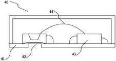
- Fig. 13shows a schematic diagram of a microphone monomer according to an embodiment disclosed herein.
- the microphone unit 40includes a unit housing 41, the above-described capacitive MEMS microphone 42 and an integrated circuit chip 43.
- the capacitive MEMS microphone 42 and the integrated circuit chip 43are arranged in the single housing 42.
- the capacitive MEMS microphone 42corresponds to the air inlet of the single housing 41.
- the capacitance-type MEMS microphone 42, the integrated circuit chip 43 and the circuit in the unit housing 41are connected by a lead 44.
- Fig. 14shows a schematic diagram of an electronic device according to an embodiment disclosed herein.
- the electronic device 50may include the microphone unit 51 shown in FIG. 8.
- the electronic device 50may be a mobile phone, a tablet computer, a wearable device, or the like.
Landscapes
- Engineering & Computer Science (AREA)
- Physics & Mathematics (AREA)
- Acoustics & Sound (AREA)
- Signal Processing (AREA)
- Multimedia (AREA)
- Electrostatic, Electromagnetic, Magneto- Strictive, And Variable-Resistance Transducers (AREA)
- Pressure Sensors (AREA)
Abstract
Description
Translated fromChinese本说明书涉及电容型微机电系统麦克风技术领域,更具体地,涉及一种电容型微机电系统麦克风、麦克风单体及电子设备。This specification relates to the technical field of condenser MEMS microphones, and more specifically, to a condenser MEMS microphone, a microphone unit and electronic equipment.
微机电系统(MEMS)麦克风是采用微机电技术制造的麦克风芯片。它具有较小的体积,并可以广泛应用于各种电子设备,例如,手机、平板电脑、监控设备、可穿戴设备等。Micro-Electro-Mechanical System (MEMS) microphone is a microphone chip manufactured using micro-electro-mechanical technology. It has a small volume and can be widely used in various electronic devices, such as mobile phones, tablet computers, monitoring devices, wearable devices, etc.
电容型微机电系统麦克风使用双端电容的结构。图1示出了一种电容型电容型微机电系统麦克风的结构。如图1所示,电容型微机电系统麦克风包括背极板11、振膜12以及位于背极板11和振膜12之间的间隔件13。间隔件13用于将背极板11和振膜12隔开。间隔件13可以单独的间隔层也可以是芯片衬底的一部分。Capacitive MEMS microphones use a double-ended capacitor structure. Figure 1 shows the structure of a capacitor-type capacitive MEMS microphone. As shown in FIG. 1, the capacitive MEMS microphone includes a
在图1中,背极板11、振膜12和间隔件13围成电容型微机电系统麦克风的后腔15。在背极板11中可以形成连通到后腔15的孔14。在振膜12中还可以形成泄气孔(未示出)。In FIG. 1, the
如图2所示,振膜12在施加工作偏压的状态下向背极板11弯曲。为了保证振膜12的机械线性性能,在施加工作偏压的情况下,当振膜12处于静止状态时,振膜12具有较小的静态挠度,即,振膜12相对于平整位置的静态有效位移(静态有效挠度)与振膜12的厚度的比值W0/t<0.5,其中,W0是在工作偏压下振膜12在静止状态下的有效位移,t是振膜12的厚度。As shown in FIG. 2, the
图2的振膜12被设置成具有较大的硬度,以使得振膜12具有较小的静态挠度。这种振膜的灵敏度较低。The
因此,需要提供一种新的电容型微机电系统麦克风。Therefore, it is necessary to provide a new capacitive MEMS microphone.
发明内容Summary of the invention
本说明书的实施例提供用于电容型微机电系统麦克风的新技术方案。The embodiments of this specification provide a new technical solution for a condenser MEMS microphone.
根据本说明书的第一方面,提供了一种电容型微机电系统麦克风,包括:背极板;振膜;以及间隔件,用于使得所述背极板和振膜间隔开,其中,在未施加工作偏压的状态下,相对于平整位置,沿背离所述背极板的方向,所述振膜的至少一部分被预先拉偏。According to the first aspect of this specification, there is provided a capacitive microelectromechanical system microphone, including: a back plate; a diaphragm; and a spacer for separating the back plate and the diaphragm. When the working bias is applied, at least a part of the diaphragm is biased in advance in a direction away from the back plate relative to the flat position.
根据本说明书的第二方面,提供了一种麦克风单体,包括单体外壳、这里公开的电容型微机电系统麦克风以及集成电路芯片,其中,所述电容型微机电系统麦克风以及集成电路芯片被设置在所述单体外壳中。According to the second aspect of this specification, there is provided a microphone unit, including a unit housing, the capacitive MEMS microphone and the integrated circuit chip disclosed herein, wherein the capacitive MEMS microphone and the integrated circuit chip are Set in the single housing.
根据本说明书的第三方面,提供了一种电子设备,包括这里公开的麦克风单体。According to the third aspect of this specification, there is provided an electronic device including the microphone monomer disclosed herein.
在不同实施例中,通过使用较大静态挠度的振膜,可以降低麦克风的整体非线性。In different embodiments, by using a diaphragm with a larger static deflection, the overall nonlinearity of the microphone can be reduced.
应当理解的是,以上的一般描述和后文的细节描述仅是示例性和解释性的,并不能限制本说明书实施例。It should be understood that the above general description and the following detailed description are only exemplary and explanatory, and cannot limit the embodiments of this specification.
此外,本说明书实施例中的任一实施例并不需要达到上述的全部效果。In addition, any one of the embodiments of the present specification does not need to achieve all the above-mentioned effects.
通过以下参照附图对本说明书的示例性实施例的详细描述,本说明书的实施例的其它特征及其优点将会变得清楚。Through the following detailed description of exemplary embodiments of the present specification with reference to the accompanying drawings, other features and advantages of the embodiments of the present specification will become clear.
为了更清楚地说明本说明书实施例或现有技术中的技术方案,下面将对实施例或现有技术描述中所需要使用的附图作简单地介绍,显而易见地,下面描述中的附图仅仅是本说明书实施例中记载的一些实施例,对于本领域普通技术人员来讲,还可以根据这些附图获得其他的附图。In order to more clearly describe the technical solutions in the embodiments of this specification or the prior art, the following will briefly introduce the drawings that need to be used in the description of the embodiments or the prior art. Obviously, the drawings in the following description are only These are some of the embodiments described in the embodiments of this specification. For those of ordinary skill in the art, other drawings can also be obtained based on these drawings.
图1示出了现有技术的微机电麦克风的示意图。Fig. 1 shows a schematic diagram of a microelectromechanical microphone in the prior art.
图2示出了现有技术的微机电麦克风的示意图,其中,振膜在施加工作偏压的状态下具有较小的静态挠度。Fig. 2 shows a schematic diagram of a microelectromechanical microphone in the prior art, in which the diaphragm has a relatively small static deflection when a working bias is applied.
图3示出了振膜在静止状态下的有效位移与工作偏压的关系的曲线图。Fig. 3 shows a graph of the relationship between the effective displacement of the diaphragm in a static state and the working bias voltage.
图4示出了关于振膜的声学过载点的示意图。Fig. 4 shows a schematic diagram of the acoustic overload point of the diaphragm.
图5示出了根据这里公开的一个实施例的电容型微机电系统麦克风的示意图。Fig. 5 shows a schematic diagram of a capacitive microelectromechanical system microphone according to an embodiment disclosed herein.
图6示出了根据这里公开的另一个实施例的电容型微机电系统麦克风的示意图。Fig. 6 shows a schematic diagram of a capacitive MEMS microphone according to another embodiment disclosed herein.
图7示出了根据这里公开的又一个实施例的电容型微机电系统麦克风的示意图。Fig. 7 shows a schematic diagram of a capacitive MEMS microphone according to another embodiment disclosed herein.
图8示出了根据这里公开的又一个实施例的电容型微机电系统麦克风的示意图。Fig. 8 shows a schematic diagram of a capacitive microelectromechanical system microphone according to another embodiment disclosed herein.
图9示出了根据这里公开的又一个实施例的电容型微机电系统麦克风的示意图。Fig. 9 shows a schematic diagram of a capacitive microelectromechanical system microphone according to another embodiment disclosed herein.
图10示出了根据这里公开的又一个实施例的电容型微机电系统麦克风的示意图。Fig. 10 shows a schematic diagram of a capacitive microelectromechanical system microphone according to another embodiment disclosed herein.
图11示出了根据这里公开的又一个实施例的电容型微机电系统麦克风的示意图。FIG. 11 shows a schematic diagram of a capacitive MEMS microphone according to another embodiment disclosed herein.
图12示出了根据这里公开的一个实施例的麦克风单体的示意图。Fig. 12 shows a schematic diagram of a microphone monomer according to an embodiment disclosed herein.
图13示出了根据这里公开的一个实施例的电子设备的示意图。FIG. 13 shows a schematic diagram of an electronic device according to an embodiment disclosed herein.
现在将参照附图来详细描述各种示例性实施例。Various exemplary embodiments will now be described in detail with reference to the accompanying drawings.
以下对至少一个示例性实施例的描述实际上仅仅是说明性的,决不作为对本发明及其应用或使用的任何限制。The following description of at least one exemplary embodiment is actually only illustrative, and in no way serves as any limitation to the present invention and its application or use.
应注意到:相似的标号和字母在下面的附图中表示类似项,因此,一旦某一项在一个附图中被定义,则在随后的附图中不需要对其进行进一步讨论。It should be noted that similar reference numerals and letters indicate similar items in the following drawings, therefore, once an item is defined in one drawing, it does not need to be further discussed in the subsequent drawings.
下面,参照附图描述本说明书的不同实施例和例子。Hereinafter, different embodiments and examples of this specification will be described with reference to the drawings.
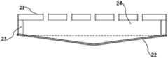
在这里,提出了一种电容型微机电系统麦克风。如图5所示,电容型微机电系统麦克风包括:背极板21、振膜22以及间隔件23。间隔件23用 于使得背极板21和振膜22间隔开。间隔件23可以是单独的间隔层,也可以是芯片衬底的一部分。Here, a capacitive MEMS microphone is proposed. As shown in FIG. 5, the capacitive MEMS microphone includes: a
图5示出了未对振膜22施加工作偏压的情况。在未施加工作偏压的状态下,相对于图5中虚线所示的平整位置,沿背离所述背极板的方向(即,使得振膜22和背极板21之间的间距增大的方向),振膜22的至少一部分被预先拉偏。在图5中,振膜22整体被预先拉偏。但是,在其他实施例中,可以将振膜分成多个部分,并且可以将其中的一部分预先拉偏。在这里,预先拉偏指的是在振膜在声压下进行工作之前的拉偏状态。FIG. 5 shows the case where the operating bias voltage is not applied to the
振膜22的至少一部分被预先拉偏的第一静态有效位移W00与振膜的厚度t的比值大于等于0.2且小于等于3,即,0.2<=W00/t>=3。The ratio of the first static effective displacement W 00 at which at least a part of the
例如,在图5中的MEMS麦克风中,虚线所示的平整位置与背极板21之间的空气间隙G00=1-5um,振膜22的厚度t=0.1-1.5um。For example, in the MEMS microphone in FIG. 5, the air gap G00 between the flat position shown by the dashed line and the
通过这种预先拉偏的设置,可以增大了振膜强度,从而改善THD(总谐波失真)和/或AOP(声学过载点)。Through this pre-deflection setting, the strength of the diaphragm can be increased, thereby improving THD (Total Harmonic Distortion) and/or AOP (Acoustic Overload Point).
此外,由于对振膜进行预先拉偏,因此,当施加工作电压时,可以在一定程度上避免振膜被压到背极板。另外,对振膜进行预先拉偏的应力也会对振膜本身的应力分布产生影响。通过预先拉偏的方式,可以制造较小间隙的MEMS麦克风。这使得制作工艺容易、器件下塌电压VP较低。此外,这种方式可以降低对MEMS麦克风的偏压供电要求。例如,15V以下的标准CMOS电压可以满足它的偏压供电要求,而无需使用高压BCD(Bipolar-CMOS-DMOS)工艺。这可以减小MEMS麦克风的芯片面积,并降低成本。In addition, since the diaphragm is pre-biased, when the working voltage is applied, the diaphragm can be prevented from being pressed to the back plate to a certain extent. In addition, the pre-deflection stress on the diaphragm will also affect the stress distribution of the diaphragm itself. By pre-deflection, a MEMS microphone with a smaller gap can be manufactured. This makes the manufacturing process easy and the device collapse voltage VP is low. In addition, this approach can reduce the bias power supply requirements for the MEMS microphone. For example, a standard CMOS voltage below 15V can meet its bias power supply requirements without using a high-voltage BCD (Bipolar-CMOS-DMOS) process. This can reduce the chip area of the MEMS microphone and reduce the cost.
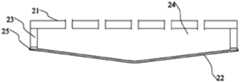
图6、7示出了在施加工作偏压的情况下振膜22的两种状态。如图6所示,在施加工作偏压的情况下,振膜22离开原始的位置221,但是,仍然位于虚线所示的振膜平整位置之外(远离背极板21)。在图7中,在施加工作偏压的情况下,振膜22离开原始的位置221,并且位于虚线所示的振膜平整位置之内(靠近背极板21)。Figures 6 and 7 show two states of the
在图6、7所示的实施例中,在施加工作偏压的状态下,可以将振膜22相对于平整位置的第二静态有效位移与振膜的厚度的比值大于或等于0.5,优选地,大于或等于1。这里,“静态”指的是未施加声压的状态。In the embodiment shown in FIGS. 6 and 7, under the state of applying the working bias, the ratio of the second static effective displacement of the
通过这种方式,可以使得振膜的机械非线性达到与电容检测的非线性幅度近似但方向相反的程度,从而大大降低MEMS麦克风的整体非线性,以进一步改善THD和AOP性能。In this way, the mechanical nonlinearity of the diaphragm can be made to a degree similar to that of the capacitance detection but in the opposite direction, thereby greatly reducing the overall nonlinearity of the MEMS microphone, so as to further improve the THD and AOP performance.
下面,结合图3、4解释图6、7所示的包含背极板21和振膜22的电容型MEMS麦克风的工作原理及性能。这种电容型MEMS麦克风又可以称为双端电容型微机电系统麦克风。图6、7的电容型MEMS麦克风的振膜22具有较大的挠度。Next, in conjunction with FIGS. 3 and 4, the working principle and performance of the capacitive MEMS microphone including the
在电容型微机电系统麦克风中,电荷总量是常量(固定的),即,在音频频率下,电量Q=CV为常数,其中,C、V分别为振膜和背极板之间的电容、电压。所以,信号输出可以表示为:In a capacitive MEMS microphone, the total charge is constant (fixed), that is, at the audio frequency, the power Q=CV is a constant, where C and V are the capacitance between the diaphragm and the back plate, respectively ,Voltage. Therefore, the signal output can be expressed as:
vo=-x/(1-x)·VB (公式1)vo=-x/(1-x)·VB (Formula 1)
其中x=w/G0,它是振膜22的位移w与背极板21和振膜22之间静态空气间隙G0的比值,VB为背极板21和振膜22之间的工作偏压。静态空气间隙G0是在施加工作偏压VB下振膜和背极板之间的有效静态空气间隙。VB可以表示使得振膜能够处于期望工作状态的偏置电压。Where x=w/G0 , which is the ratio of the displacement w of the
在通过背极板和振膜之间电容检测来获取输出信号时,电容检测所产生的非线性可以表示为:When the output signal is obtained through the capacitance detection between the back plate and the diaphragm, the nonlinearity generated by the capacitance detection can be expressed as:
|vo+/vo-|=[(1-x-)/(1-x+)]·(x+/x-) (公式2)| vo + / vo - | = [(1-x -) / (1-x +)] · (x + / x -) ( Equation 2)
其中,公式2中的vo和x的含义如上所述,以及上标+、-分别对应振膜所接受的声压的正、负半周期。当声压为正时,x朝向空气间隙G减小的方向变化。公式2表明了双端电容型MEMS麦克风的非线性的主要来源之一。Among them, the meanings of vo and x in
传统的麦克风利用振膜的机械线性性能,即,尽量使得振膜的位移w正比于声压p,即,x-=-x+,x+=x>0,其中,对于x,朝向空气间隙G减小的方向为正。此时,麦克风的非线性可以表示为:Using a conventional diaphragm microphone linear mechanical properties, i.e., as much as possible so that the diaphragm displacement w is proportional to the sound pressure p,i.e., x - = -x +, x + = x> 0, wherein, for x, toward the air gap The direction in which G decreases is positive. At this time, the nonlinearity of the microphone can be expressed as:
|vo+/vo-|=(1+x)/(1-x) (公式3)| vo + / vo - | = (1 + x) / (1-x) ( Equation 3)
在公式3中,正信号输出大于负信号输出,并且麦克风的非线性程度和x直接相关。In formula 3, the positive signal output is greater than the negative signal output, and the degree of non-linearity of the microphone is directly related to x.
此外,振膜本身的机械非线性可以表示为:In addition, the mechanical nonlinearity of the diaphragm itself can be expressed as:
P=aW+bW3 (公式4)P=aW+bW3 (Equation 4)
其中,P、W为振膜所接受的总压力、总位移量,a、b正的常数。Among them, P and W are the total pressure and displacement received by the diaphragm, and a and b are positive constants.
振膜在静态状态(即,在施加工作偏压VB但是未施加声压p的状态)下的静态有效位移(工作偏压下的有效位移)是W0。由于在电容型麦克风的振膜和背极板之间施加工作偏压VB,因此,W0>0。当有声压p施加到振膜上时,在声压p的正半周期(正声压)时振膜的位移量是w+,在声压p的负半周期(负声压)时振膜的位移量是w-,w+略小于w-。The static effective displacement (effective displacement under the working bias) of the diaphragm in the static state (that is, the state where the working bias voltage VB is applied but the sound pressure p is not applied) is W0 . Since the working bias voltage VB is applied between the diaphragm and the back plate of the condenser microphone, W0 >0.When sound pressure p is applied to the diaphragm, the displacement of the diaphragm is w + in the positive half period of sound pressure p (positive sound pressure), and the diaphragm is in the negative half period of sound pressure p (negative sound pressure). the amount of displacement is w-, w+ slightly smaller than w-.
公式4还可以表示为:Equation 4 can also be expressed as:
p+P0=a(W0+w)+b(W0+w)3 (公式5)p+P0 =a(W0 +w)+b(W0 +w)3 (Equation 5)
其中,p为声压(具有正、负半周期)),P0>0为由静电力产生的静态压力,w为声压所产生的额外振膜位移(可以是正或负的值)。Among them, p is the sound pressure (with positive and negative half-periods)), P0 > 0 is the static pressure generated by the electrostatic force, and w is the additional diaphragm displacement generated by the sound pressure (which can be a positive or negative value).
图3示出了静态有效位移W0和工作偏压VB的关系。在图3中,横坐标是VB/VP,其中,VP表示麦克风的下塌电压;纵坐标是W0/G0。为保证麦克风器件的可靠性,通常设置VB/VP<75%,对应的W0/G0约为16%。通过设置VB可以调整振膜22的静态挠度,或者调整振膜22相对于平整位置的静态有效位移W0与振膜的厚度t的比值W0/t。Fig. 3 shows the relationship between the static effective displacement W0 and the working bias voltage VB. In Figure 3, the abscissa is VB/VP, where VP represents the microphone's collapse voltage; the ordinate is W0 /G0 . In order to ensure the reliability of the microphone device, usually set VB/VP<75%, and the corresponding W0 /G0 is about 16%. By setting VB, the static deflection of the
在传统的电容型MEMS麦克风中,为了追求机械线性,需要选择在静态(未施加声压)时具有较小静态挠度的振膜,或者振膜22相对于平整位置的静态有效位移W0与振膜的厚度t的比值W0/t<=0.5。这种麦克风的非线性主要来自电容检测。In a traditional capacitive MEMS microphone, in order to pursue mechanical linearity, it is necessary to select a diaphragm with a small static deflection when static (no sound pressure is applied), or the static effective displacement W0 of the diaphragm 22 relative to the flat position and the vibration The ratio of the thickness t of the film W0 /t<=0.5. The non-linearity of this microphone mainly comes from capacitance detection.
在这里,我们提出通过增大振膜的静态挠度来抵消电容检测的非线性。Here, we propose to offset the nonlinearity of capacitance detection by increasing the static deflection of the diaphragm.
具体来说,综合考虑上面的公式1-5,电容型MEMS麦克风的总体非线性可以表示为:Specifically, considering the above formulas 1-5, the overall nonlinearity of a capacitive MEMS microphone can be expressed as:
|vo+/vo-|=A·B (公式6)| vo + / vo - | = A · B ( Formula 6)
其中,A=(1-x-)/(1-x+)~(1+x)/(1-x)>1,Among them, A=(1-x-)/(1-x+)~(1+x)/(1-x)>1,
B=(x+/x-)=[a+3b(W0+w-)2]/[a+3b(W0+w+)2]B = (x + / x - ) = [a + 3b (
~[a+3b(W0-w)]/[a+3b(W0+w)]<1,其中w+=w~-w->0。~[a+3b(W0 -w)]/[a+3b(W0 +w)]<1, where w+=w~-w->0.
如果综合考虑电容型MEMS麦克风的非线性,可以发现公式6中的A>1,而B<1。因此,可以通过调整A或B来降低信号输出的正负周期的不对称所造成的非线性,从而改善THD(总谐波失真)和AOP(声学过载点)。If the nonlinearity of the capacitive MEMS microphone is considered comprehensively, it can be found that A>1 and B<1 in formula 6. Therefore, the nonlinearity caused by the asymmetry of the positive and negative cycles of the signal output can be reduced by adjusting A or B, thereby improving THD (Total Harmonic Distortion) and AOP (Acoustic Overload Point).
在这个发明中,通过利用工作偏压VB和/或预先拉偏,调整“预偏移量”(振膜静态挠度),使得W0/t>=0.5,优选地,W0/t>=1。通过这种预偏移方式,可以使得公式6中的A和B至少部分抵消,从而改善输出信号的非线性程度或特定非线性程度下的声压级。例如,1%THD的声压级或10%THD对应的AOP都可大幅提高。In this invention, by using the working bias VB and/or pre-biasing, the "pre-offset" (static deflection of the diaphragm) is adjusted so that W0 /t>=0.5, preferably, W0 /t>= 1. Through this pre-offset method, A and B in formula 6 can be at least partially cancelled, thereby improving the degree of non-linearity of the output signal or the sound pressure level under a certain degree of non-linearity. For example, the sound pressure level of 1% THD or the AOP corresponding to 10% THD can be greatly improved.
图4示出了预偏移量与AOP的关系。在图4中,横坐标表示振膜的静态挠度与振膜厚度的比值W0/t,纵坐标表示静态压力P0。在图4中,实线表示较软的振膜S的性质,虚线表示较硬的振膜H的性质。如图4所示,在振膜S的初始静态挠度较小的情况下,振膜S的AOP1较小。如果采用较硬的振膜H,在较小的静态挠度下,振膜H的AOP3较小。但是,较硬的振膜H可能会降低灵敏度。当将振膜S的静态挠度设置得较大时,例如,当将振膜S的静态挠度设置在与(W0,P0)对应的点时,振膜S的AOP2相对于AOP1显著增加。通过这种方式,可以在保留较软振膜的优点(例如,灵敏度)的情况下增加AOP等性能。Figure 4 shows the relationship between pre-offset and AOP.In Fig. 4, the abscissa represents the ratio W 0 /t of the static deflection of the diaphragm to the thickness of the diaphragm, and the ordinate represents the static pressure P0 . In FIG. 4, the solid line represents the properties of the softer diaphragm S, and the broken line represents the properties of the harder diaphragm H. As shown in FIG. 4, when the initial static deflection of the diaphragm S is small, the AOP1 of the diaphragm S is small. If a harder diaphragm H is used, under a smaller static deflection, the AOP3 of the diaphragm H is smaller. However, the harder diaphragm H may reduce sensitivity. When the static deflection of the diaphragm S is set larger, for example, when the static deflection of the diaphragm S is set ata point corresponding to (W 0 , P0 ), the AOP2 of the diaphragm S is significantly increased relative to AOP1. In this way, performance such as AOP can be increased while retaining the advantages of a softer diaphragm (for example, sensitivity).
在这里,可以通过预先拉偏,使得振膜预先处于具有较大挠度的状态。如图6所示,当施加工作电压时,振膜22向背极板21移动,但是,仍然位于虚线所示的平整位置之外。此外,如图7所示,也可以通过施加工作偏压,使得振膜22位于虚线所示的平整位置之内。在施加工作电压的情况下,图6和图7所示的振膜都具有加大的挠度。这样,可以可以人为地引进振膜机械(几何)非线性,即,声压正、负半周期内机械响应的不对称性。当施加正声压(压向背极板)时振膜的变形是w+,当施加负声压(背离背极板)时振膜的变形是w-,w+小于w-。这可以弥补由于电容检测引进来的非线性,即,输出信号可以表示为vout~-x/(1-x)VB,其中x=w/G0,w为声压造成的振膜位移,G0为在施加工作偏压且未施加声压的情况下的静 态等效的空气间隙,VB为工作偏压。在正声压下,x>0,输出信号大于x*VB;而在负声压下,输出信号小于x*VB。考虑在特定声压级下w+/w-~(1-x)/(1+x),可以利用振膜的机械非线性来弥补电容检测造成的非线性,从而改善电容型MEMS麦克风的THD和AOP。Here, it is possible to pre-pull the diaphragm so that the diaphragm is preliminarily in a state with greater flexibility. As shown in FIG. 6, when the working voltage is applied, the
可以通过应力结构,对所述振膜的至少一部分进行预先拉偏。图8-12示出了进行预先拉偏的实施例。At least a part of the diaphragm can be pre-tensioned by a stress structure. Figures 8-12 show an embodiment of pre-deflection.
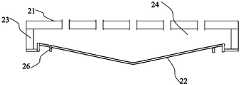
在图8所示的实施例中,通过设置在所述振膜周边的应力环25来实现所述应力结构。应力环25可以包括张应力环和/或压应力环。例如,在由自由多晶硅制成的振膜22的内侧周边(靠近背极板21的一侧周边)设置一层张应力氮化硅薄膜环,和/或在外侧周边(靠近背极板21的一侧周边)设置一层压应力薄膜环。In the embodiment shown in FIG. 8, the stress structure is realized by a
在图9所示的实施例中,通过设置在所述振膜周边的纹膜26来实现所述应力结构。通过设置纹膜的不同方向,可以向振膜22提供不同的应力。例如,可以通过朝向内侧(朝向背极板21)的纹提供张应力,以及通过朝向外侧的纹提供压应力。In the embodiment shown in FIG. 9, the stress structure is realized by a
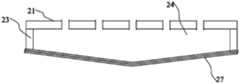
在图10所示的实施例中,通过设置在所述振膜上的复合膜结构27来实现所述应力结构。例如,在图10所示的复合膜结构27包括内侧膜和外侧膜,内侧膜具有压应力,外侧膜具有张应力,从而使得振膜被预先拉偏。In the embodiment shown in FIG. 10, the stress structure is realized by a
图11、12示出了通过支撑结构来预先拉偏振膜的实施例。Figures 11 and 12 show an embodiment in which the polarizing film is pre-drawn through the support structure.
在图11的实施例中,支撑件28位于振膜和背极板之间的支撑件。支撑件28的一端被固定到背极板21,支撑件28的另一端被固定到振膜22并将振膜22分成至少两部分。在加工时,由于应力作用,支撑件28可以发生形变,从而发生倾斜。支撑件28的形变使得振膜的至少两部分中的一部分相对于背极板21向外拉偏并使得另一部分相对于背极板21向内拉偏,如图11所示。通过这种方式,可以使得振膜产生两种不同方向的拉偏,并且,两种不同方向的拉偏可以平衡振膜的性能。In the embodiment of FIG. 11, the
此外,为了减小寄生电容,支撑件28可以是柱状体。In addition, in order to reduce parasitic capacitance, the
在图12的例子中,支撑件29位于振膜22和背极板21之间。支撑件29的一端被固定到背极板,支撑件29的另一端支撑翘起元件30。翘起元 件30的第一侧与振膜22接触,翘起元件30的第二侧具有静电电路31。当施加工作偏压时,静电电路31被背极板21吸引,以使得翘起元件30的第一侧推动所述振膜向外侧凸起,如图12所示。在这种方式中,可以通过控制静电电路31中的电量来控制振膜被预先拉偏的程度。In the example of FIG. 12, the
图13示出了根据这里公开的一个实施例的麦克风单体的示意图。Fig. 13 shows a schematic diagram of a microphone monomer according to an embodiment disclosed herein.
如图13所示,麦克风单体40包括单体外壳41、上面描述的电容型MEMS麦克风42以及集成电路芯片43。电容型MEMS麦克风42以及集成电路芯片43被设置在所述单体外壳42中。电容型MEMS麦克风42与单体外壳41的进气口对应。电容型MEMS麦克风42、集成电路芯片43和单体外壳41中的电路通过引线44连接。As shown in FIG. 13, the
图14示出了根据这里公开的一个实施例的电子设备的示意图。Fig. 14 shows a schematic diagram of an electronic device according to an embodiment disclosed herein.
如图14所示,电子设备50可以包括图8所示的麦克风单体51。电子设备50可以是手机、平板电脑、可穿戴设备等。As shown in FIG. 14, the
以上所述仅是本说明书实施例的具体实施方式,应当指出,对于本技术领域的普通技术人员来说,在不脱离本说明书实施例原理的前提下,还可以做出若干改进和润饰,这些改进和润饰也应视为本说明书实施例的保护范围。The above are only specific implementations of the embodiments of this specification. It should be pointed out that for those of ordinary skill in the art, without departing from the principle of the embodiments of this specification, several improvements and modifications can be made. These Improvements and retouching should also be regarded as the protection scope of the embodiments of this specification.
Claims (10)
Translated fromChinesePriority Applications (1)
| Application Number | Priority Date | Filing Date | Title |
|---|---|---|---|
| US18/010,907US12382227B2 (en) | 2020-06-16 | 2020-06-30 | Capacitive MEMS microphone, microphone unit and electronic device |
Applications Claiming Priority (2)
| Application Number | Priority Date | Filing Date | Title |
|---|---|---|---|
| CN202010548789.X | 2020-06-16 | ||
| CN202010548789.XACN111885471B (en) | 2020-06-16 | 2020-06-16 | Condenser MEMS microphone, microphone monomer and electronic equipment |
Publications (1)
| Publication Number | Publication Date |
|---|---|
| WO2021253499A1true WO2021253499A1 (en) | 2021-12-23 |
Family
ID=73158365
Family Applications (1)
| Application Number | Title | Priority Date | Filing Date |
|---|---|---|---|
| PCT/CN2020/099425CeasedWO2021253499A1 (en) | 2020-06-16 | 2020-06-30 | Capacitive micro-electro-mechanical system microphone, microphone unit, and electronic device |
Country Status (3)
| Country | Link |
|---|---|
| US (1) | US12382227B2 (en) |
| CN (1) | CN111885471B (en) |
| WO (1) | WO2021253499A1 (en) |
Families Citing this family (1)
| Publication number | Priority date | Publication date | Assignee | Title |
|---|---|---|---|---|
| CN113613151B (en)* | 2021-07-30 | 2023-08-04 | 歌尔微电子股份有限公司 | MEMS microphone, microphone monomer and electronic equipment |
Citations (5)
| Publication number | Priority date | Publication date | Assignee | Title |
|---|---|---|---|---|
| US20060280319A1 (en)* | 2005-06-08 | 2006-12-14 | General Mems Corporation | Micromachined Capacitive Microphone |
| US20150014797A1 (en)* | 2013-07-12 | 2015-01-15 | Robert Bosch Gmbh | Mems device having a microphone structure, and method for the production thereof |
| CN108367908A (en)* | 2015-12-18 | 2018-08-03 | 罗伯特·博世有限公司 | Centrally fixed MEMS microphone membrane |
| US20180352339A1 (en)* | 2017-05-31 | 2018-12-06 | Cirrus Logic International Semiconductor Ltd. | Mems devices and processes |
| CN110351641A (en)* | 2018-04-02 | 2019-10-18 | 鑫创科技股份有限公司 | MEMS condenser microphone |
Family Cites Families (6)
| Publication number | Priority date | Publication date | Assignee | Title |
|---|---|---|---|---|
| KR101150186B1 (en)* | 2009-12-04 | 2012-05-25 | 주식회사 비에스이 | Mems microphone and munufacturing method of the same |
| US8629011B2 (en)* | 2011-06-15 | 2014-01-14 | Robert Bosch Gmbh | Epitaxial silicon CMOS-MEMS microphones and method for manufacturing |
| DE102012200957A1 (en)* | 2011-07-21 | 2013-01-24 | Robert Bosch Gmbh | Component with a micromechanical microphone structure |
| KR101614330B1 (en)* | 2013-08-06 | 2016-04-21 | 고어텍 인크 | An anti-impact silicon based mems microphone, a system and a package with the same |
| CN107105377B (en)* | 2017-05-15 | 2021-01-22 | 潍坊歌尔微电子有限公司 | A MEMS microphone |
| CN206932407U (en)* | 2017-06-30 | 2018-01-26 | 歌尔科技有限公司 | Mems microphone |
- 2020
- 2020-06-16CNCN202010548789.XApatent/CN111885471B/enactiveActive
- 2020-06-30WOPCT/CN2020/099425patent/WO2021253499A1/ennot_activeCeased
- 2020-06-30USUS18/010,907patent/US12382227B2/enactiveActive
Patent Citations (5)
| Publication number | Priority date | Publication date | Assignee | Title |
|---|---|---|---|---|
| US20060280319A1 (en)* | 2005-06-08 | 2006-12-14 | General Mems Corporation | Micromachined Capacitive Microphone |
| US20150014797A1 (en)* | 2013-07-12 | 2015-01-15 | Robert Bosch Gmbh | Mems device having a microphone structure, and method for the production thereof |
| CN108367908A (en)* | 2015-12-18 | 2018-08-03 | 罗伯特·博世有限公司 | Centrally fixed MEMS microphone membrane |
| US20180352339A1 (en)* | 2017-05-31 | 2018-12-06 | Cirrus Logic International Semiconductor Ltd. | Mems devices and processes |
| CN110351641A (en)* | 2018-04-02 | 2019-10-18 | 鑫创科技股份有限公司 | MEMS condenser microphone |
Also Published As
| Publication number | Publication date |
|---|---|
| CN111885471B (en) | 2021-10-08 |
| CN111885471A (en) | 2020-11-03 |
| US12382227B2 (en) | 2025-08-05 |
| US20230353951A1 (en) | 2023-11-02 |
Similar Documents
| Publication | Publication Date | Title |
|---|---|---|
| CN210609708U (en) | MEMS microphones and electronics | |
| US10433070B2 (en) | Sensitivity compensation for capacitive MEMS device | |
| TWI667925B (en) | Piezoelectric transducer | |
| US20190245133A1 (en) | Piezoelectric device | |
| CN113507676B (en) | Structure and device of silicon-based cantilever MEMS piezoelectric microphone | |
| CN109511067A (en) | Electret Condencer Microphone | |
| TW201808783A (en) | MEMS device and process | |
| CN113613151B (en) | MEMS microphone, microphone monomer and electronic equipment | |
| WO2022142507A1 (en) | Mems microphone and diaphragm structure thereof | |
| US20250250157A1 (en) | Mems transducer | |
| CN100455142C (en) | Capacitive microelectromechanical structure sound sensor | |
| WO2021253501A1 (en) | Absolute pressure sensing micro electromechanical system microphone, microphone unit and electronic device | |
| WO2021253499A1 (en) | Capacitive micro-electro-mechanical system microphone, microphone unit, and electronic device | |
| CN114339557B (en) | MEMS microphone chip, preparation method thereof and MEMS microphone | |
| US12284483B2 (en) | Capacitive MEMS microphone, microphone unit and electronic device | |
| CN112291694B (en) | MEMS transducer and method for operating the same | |
| US20240425353A1 (en) | Acoustic sensor device with multi-sided anchor | |
| CN115334389B (en) | Microphone assembly and electronic equipment | |
| US20250220359A1 (en) | Mems microphone and electronic device | |
| WO2024140770A1 (en) | Sensor, detection method of sensor, and electronic device | |
| CN114390418A (en) | MEMS electrode formation method | |
| CN118265436A (en) | Piezoelectric MEMS sensor, adjusting method and electronic equipment | |
| CN118921609A (en) | MEMS capacitor a sensor(s) microphone | |
| WO2018061805A1 (en) | Piezoelectric type microphone | |
| CN118843052A (en) | MEMS structures and sensors |
Legal Events
| Date | Code | Title | Description |
|---|---|---|---|
| 121 | Ep: the epo has been informed by wipo that ep was designated in this application | Ref document number:20940785 Country of ref document:EP Kind code of ref document:A1 | |
| NENP | Non-entry into the national phase | Ref country code:DE | |
| 32PN | Ep: public notification in the ep bulletin as address of the adressee cannot be established | Free format text:NOTING OF LOSS OF RIGHTS PURSUANT TO RULE 112(1) EPC (EPO FORM 1205 DATED 29.03.2023) | |
| 122 | Ep: pct application non-entry in european phase | Ref document number:20940785 Country of ref document:EP Kind code of ref document:A1 | |
| WWG | Wipo information: grant in national office | Ref document number:18010907 Country of ref document:US |