WO2021246631A1 - Vacuum cleaner - Google Patents
Vacuum cleanerDownload PDFInfo
- Publication number
- WO2021246631A1 WO2021246631A1PCT/KR2021/004127KR2021004127WWO2021246631A1WO 2021246631 A1WO2021246631 A1WO 2021246631A1KR 2021004127 WKR2021004127 WKR 2021004127WWO 2021246631 A1WO2021246631 A1WO 2021246631A1
- Authority
- WO
- WIPO (PCT)
- Prior art keywords
- module
- drum
- connector
- housing
- socket
- Prior art date
- Legal status (The legal status is an assumption and is not a legal conclusion. Google has not performed a legal analysis and makes no representation as to the accuracy of the status listed.)
- Ceased
Links
Images


Classifications
- A—HUMAN NECESSITIES
- A47—FURNITURE; DOMESTIC ARTICLES OR APPLIANCES; COFFEE MILLS; SPICE MILLS; SUCTION CLEANERS IN GENERAL
- A47L—DOMESTIC WASHING OR CLEANING; SUCTION CLEANERS IN GENERAL
- A47L9/00—Details or accessories of suction cleaners, e.g. mechanical means for controlling the suction or for effecting pulsating action; Storing devices specially adapted to suction cleaners or parts thereof; Carrying-vehicles specially adapted for suction cleaners
- A47L9/02—Nozzles
- A47L9/04—Nozzles with driven brushes or agitators
- A47L9/0405—Driving means for the brushes or agitators
- A47L9/0411—Driving means for the brushes or agitators driven by electric motor
- A—HUMAN NECESSITIES
- A47—FURNITURE; DOMESTIC ARTICLES OR APPLIANCES; COFFEE MILLS; SPICE MILLS; SUCTION CLEANERS IN GENERAL
- A47L—DOMESTIC WASHING OR CLEANING; SUCTION CLEANERS IN GENERAL
- A47L9/00—Details or accessories of suction cleaners, e.g. mechanical means for controlling the suction or for effecting pulsating action; Storing devices specially adapted to suction cleaners or parts thereof; Carrying-vehicles specially adapted for suction cleaners
- A47L9/02—Nozzles
- A47L9/04—Nozzles with driven brushes or agitators
- A47L9/0455—Bearing means therefor
- A—HUMAN NECESSITIES
- A47—FURNITURE; DOMESTIC ARTICLES OR APPLIANCES; COFFEE MILLS; SPICE MILLS; SUCTION CLEANERS IN GENERAL
- A47L—DOMESTIC WASHING OR CLEANING; SUCTION CLEANERS IN GENERAL
- A47L9/00—Details or accessories of suction cleaners, e.g. mechanical means for controlling the suction or for effecting pulsating action; Storing devices specially adapted to suction cleaners or parts thereof; Carrying-vehicles specially adapted for suction cleaners
- A47L9/02—Nozzles
- A47L9/04—Nozzles with driven brushes or agitators
- A47L9/0461—Dust-loosening tools, e.g. agitators, brushes
- A47L9/0466—Rotating tools
- A47L9/0477—Rolls
- A—HUMAN NECESSITIES
- A47—FURNITURE; DOMESTIC ARTICLES OR APPLIANCES; COFFEE MILLS; SPICE MILLS; SUCTION CLEANERS IN GENERAL
- A47L—DOMESTIC WASHING OR CLEANING; SUCTION CLEANERS IN GENERAL
- A47L9/00—Details or accessories of suction cleaners, e.g. mechanical means for controlling the suction or for effecting pulsating action; Storing devices specially adapted to suction cleaners or parts thereof; Carrying-vehicles specially adapted for suction cleaners
- A47L9/22—Mountings for motor fan assemblies
- A—HUMAN NECESSITIES
- A47—FURNITURE; DOMESTIC ARTICLES OR APPLIANCES; COFFEE MILLS; SPICE MILLS; SUCTION CLEANERS IN GENERAL
- A47L—DOMESTIC WASHING OR CLEANING; SUCTION CLEANERS IN GENERAL
- A47L9/00—Details or accessories of suction cleaners, e.g. mechanical means for controlling the suction or for effecting pulsating action; Storing devices specially adapted to suction cleaners or parts thereof; Carrying-vehicles specially adapted for suction cleaners
- A47L9/28—Installation of the electric equipment, e.g. adaptation or attachment to the suction cleaner; Controlling suction cleaners by electric means
- A47L9/2868—Arrangements for power supply of vacuum cleaners or the accessories thereof
- A47L9/2884—Details of arrangements of batteries or their installation
Definitions
- the present inventionrelates to a vacuum cleaner having a suction head provided with a rotating drum brush, and more particularly, to a vacuum cleaner having a modular suction head structure such as a drum brush module and a motor module detachable from the suction head.
- One aspect of the present inventioncan provide a vacuum cleaner that is easy to repair, replace, or clean because the drum brush module or the motor module is detachable from the suction head.
- One aspect of the present inventionmay provide a vacuum cleaner that is stably coupled when the motor module is coupled to the suction head and can transmit driving force to the drum brush module.
- the bearing modulemay include a bearing frame mounted on a bearing module seating portion formed on an outer surface of the socket flange, and a bearing module provided to support an inner circumferential surface of the drum body.
- the bearing modulemay include a plurality of contact bearings protruding from the bearing frame and provided to be in contact with an inner circumferential surface of the drum body.
- the bearing modulemay include a drum seal disposed on inner peripheral surfaces of the bearing frame and the drum body and fixed to the bearing frame to seal a gap between the bearing frame and the drum body.
- the bearing modulemay include a socket seal disposed between the bearing frame and the socket flange and fixed to the bearing frame to seal a gap between the bearing frame and the socket flange.
- the motor modulemay further include one end at which the plug is disposed, a drum drive shaft disposed at the other end in the direction of the rotation axis, and a coupler connected to the drum drive shaft to rotate the drum body.
- the drum brush modulemay further include a coupler groove formed in the drum body so that the drum body is rotatable and engaged with the coupler.
- the drum brush moduleis disposed on the other side of the housing and includes a drum detachable cover to which the drum body of the drum brush module is rotatably coupled, the drum detachable cover fixing the drum brush module to the other side of the housing. It may include a fixing part.
- the connectorincludes a connector pin and a pin protection flange surrounding the connector pin
- the plugincludes a plug groove into which the connector pin is inserted
- an insertion flange surrounding the plug groove and provided to inscribe the pin protection flange and the insertion flangeincludes a plurality of insertion guides of different lengths protruding from the outer circumferential surface and formed along the longitudinal direction of the plug, and the inner circumferential surface of the pin protection flange corresponds to the plurality of insertion guides and the plurality of insertion guides It may include a plurality of insertion guide grooves, each of which is inserted and fixed.
- a vacuum cleanerincludes: a cleaner body having a suction force generating device for generating a suction force, and a foreign material collecting chamber for collecting foreign substances; and a suction head in which a cylindrical drum body including a brush formed on an outer circumferential surface to induce suction of the foreign substances and connected to the cleaner body to suck the foreign substances from the cleaning surface and guide the foreign substances to the foreign substance collection chamber is rotatably installed;
- the suction headthe housing having a suction port; a connector module disposed on one side of the housing and including a connector supplied with power from a battery provided in the cleaner body; a motor module provided to be detachable from the connector module and including a plug electrically connected to the connector; a drum brush module accommodating the motor module along a rotational axis direction, including the drum body rotating around the motor module, and being detachably fixed to the other side of the housing; and a bearing module disposed between the connector module and the motor module and supporting the inner circumfer
- the bearing modulemay include a bearing frame supported by an outer circumferential surface of the socket, a plurality of contact bearings protruding from the bearing frame and provided to be in contact with an inner circumferential surface of the drum body, and at least one of the bearing module and the connector module or the motor module It may include a sealing member for sealing the gap with one.
- the motor modulefurther includes one end at which the plug is disposed, a drum drive shaft disposed at the other end in the direction of the rotation axis, and a coupler connected to the drum drive shaft to rotate the drum body, wherein the drum brush module includes the drum body. It may further include a coupler groove formed inside the drum body to be rotatably engaged with the coupler.
- the coupler groovesupports the coupler and the drum driving shaft and thereby the plug is pressed in a direction to be inserted into the connector, the connector module, the bearing module, and the
- the motor module and the rotary shaft of the drum brush modulemay be provided to be arranged in a straight line.
- the suction headis modularized into a connector module fixed to one side of the housing, a socket stably connecting the bearing module and the motor module, a bearing module, a motor module, a drum brush module, etc.
- a vacuum cleanerthat is easy to repair, replace, or clean.
- FIG. 1is a view showing a vacuum cleaner according to an embodiment of the present invention.
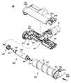
- FIG. 2is a perspective view illustrating a suction head of a vacuum cleaner according to an embodiment of the present invention.
- FIG 3is an exploded view illustrating a suction head of a vacuum cleaner according to an embodiment of the present invention.
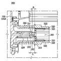
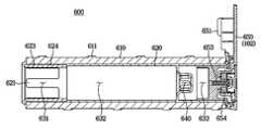
- FIG. 4is a view showing a suction head of a vacuum cleaner according to an embodiment of the present invention, and is a view showing a sectional view taken along the Y-Y line of FIG. 2 by module.
- FIG. 5is an exploded perspective view of a connector module of a vacuum cleaner and a perspective view of a socket according to an embodiment of the present invention
- FIG. 6is an enlarged view of a connector module among the drawings shown in FIG. 4 .
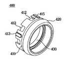
- FIG. 7is a perspective view of a bearing module of a vacuum cleaner viewed from one side according to an embodiment of the present invention.
- FIG. 8is a perspective view of a bearing module of a vacuum cleaner according to an embodiment of the present invention as viewed from a side opposite to that of FIG. 7 .
- FIG. 9is an enlarged view of the bearing module among the drawings shown in FIG. 4 .
- FIG. 10is an enlarged view of a motor module among the drawings shown in FIG. 4 .
- FIG. 14is an enlarged view of the drum brush module among the drawings shown in FIG. 4 .
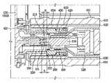
- FIG. 15is an enlarged view of a part of a cross-sectional view of a state in which each module of the drawing shown in FIG. 4 is coupled.
- FIG. 1is a view showing a vacuum cleaner according to an embodiment of the present invention.
- the vacuum cleaner 1may include a cleaner body 10 , a suction head 100 , and an extension pipe 20 connecting the cleaner body 10 and the suction head 100 .
- the suction head 100further includes a motor module 500 coupled to the connector module 200 fixed to the side housing 130 coupled to the left side of the lower housing 120 .
- the motor module 500may be provided to be separable from the connector module 200 .
- the motor module 500may include a plug 510 electrically connected to the connector module 200 .
- the plug 510may be electrically connected to the connector 210 of the connector module 200 to receive power from the battery 60 .
- the suction head 100may further include a drum brush module 600 .
- the drum brush module 600may include a drum body 620 having a cylindrical shape.
- the drum body 620may be provided in a cylindrical shape in which an empty space is formed along a rotation axis. That is, the drum body 620 may be provided in a hollow cylinder shape.
- "Hollow” in “hollow cylinder”may mean an empty space formed along the rotation axis.
- the motor module 500may be seated in an empty space formed along the axis of rotation of the drum body 620 , that is, hollow.
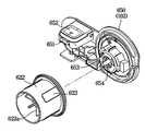
- the drum body 620may be rotatably fixed to the drum detachable cover 650 provided to be disposed on the right side of the lower housing 120 in a state in which the drum brush module 600 is finally coupled to the housing 102 .
- a fixing part 651 and a cover switch 652 in which the drum brush module 600 can be fixed to the housing 102may be provided in the drum detachable cover 650 .
- the motor module 500, the bearing module 400, the socket 300, and the connector module 200are accommodated in the empty space formed along the rotation axis of the drum body 620, and the drum brush module 600 is combined with the module. It can be finally coupled to the housing 102 by approaching in the direction X.
- FIG. 5is an exploded perspective view of a connector module of a vacuum cleaner and a perspective view of a socket 300 according to an embodiment of the present invention.
- FIG. 6is an enlarged view of a connector module among the drawings shown in FIG. 4 .
- the side housing 130 coupled to the left side of the lower housing 120is omitted.
- the connector module 200may include a connector housing 220 and a connector 210 .
- the connector 210may be physically and electrically connected to the plug 510 of the motor module 500 to perform a function of supplying power.
- the connector 210may be formed in a hollow cylinder shape having an outer diameter smaller than the hollow diameter of the connector housing 220 to be accommodated in the center of the connector housing 220 .
- one sidemay be provided in the shape of a hollow cylinder and the other side in the shape of a rectangular parallelepiped, as shown in FIG. 5 .
- the connector 210may include a connector pin 211 and a pin protection flange 212 . Similar to the connector housing 220 , the connector 210 may have an empty space formed along the center of the connector 210 .
- a connector pin 211may be formed in the above-described central portion of the connector 210 .
- a pin protection flange 212 that is spaced apart from the connector pin 211 and surrounds the connector pin 211may be formed around the connector pin 211 .
- the pin protection flange 212may be provided in a configuration corresponding to the sidewall of the hollow cylinder among the shapes of the hollow cylinder of the connector 210 described above.
- the connector pin 211 of the connector 210may be made of a metal having high electrical conductivity.
- the pin protection flange 212 surrounding the connector pin 211may be made of a material different from that of the connector pin 211 . That is, unlike the connector pin 211 , the pin protection flange 212 may be made of an insulating material.
- the connector 210is formed in the center of the pin protection flange 212 after the connector pin 211 is inserted into the empty space formed along the center. It may be fixed to finally form the connector 210 .
- both the connector pin 211 and the pin protection flange 212may be integrally formed of a metal having high electrical conductivity.
- the suction head 100 of the vacuum cleaner 1 of the present inventionmay further include a socket 300 .
- the socket 300may be disposed on the outer surface of the connector housing 220 .
- the socket 300may be fixed while surrounding the connector housing 220 on the outer surface of the connector housing 220 .
- the connector housing 220 and the socket 300may apply a coupling method in which the female screw portion formed on the inner surface of the socket 300 and the male screw portion formed on the outer surface of the connector housing 220 are bound to each other and fixed.
- various coupling methods capable of firmly coupling the connector housing 220 and the socket 300may be applied.
- the connector housing 220 and the socket 300may be integrally formed.
- a socket groove 310 into which a part of the motor module 500 is insertedmay be formed at the other side of the hollow of the socket 300 .
- a part of the motor module 500is formed in a bottle shape including a cylindrical body in which the motor module 500 is provided with a predetermined diameter, and a neck connected to the body and provided with a diameter smaller than the diameter of the body. , may correspond to the neck.
- the socket flange 320may be provided with a motor module coupling groove 321 as a structure that can further strengthen the coupling with the motor module 500 .
- the motor module coupling groove 321may be formed to correspond to the shape of the motor case fixing part 530 to be described later.
- FIG. 7is a perspective view of a bearing module of a vacuum cleaner viewed from one side according to an embodiment of the present invention.
- 8is a perspective view of a bearing module of a vacuum cleaner according to an embodiment of the present invention as viewed from a side opposite to that of FIG. 7 .
- 9is an enlarged view of the bearing module among the drawings shown in FIG. 4 .
- the plurality of contact bearings 413 shown in FIG. 7are simply formed in a protruding structure, but unlike this, an insert is formed in the bearing frame 410, and a ball bearing (not shown) is inserted into the insert to rotate in place. can
- the socket sealing 430may be fixed by a sealing hook 414 .
- the sealing hook 414may include an inner surface facing the socket and an outer surface facing the inner circumferential surface of the drum body 620 .
- the socket sealing seat 415may be formed on the inner surface of the sealing hook 414 facing the socket.
- the extended length of the sealing hook 414is formed to have a length corresponding to the width of the portion where the socket sealing 430 is seated on the sealing hook 414, so the socket sealing 430 is the sealing hook 414. By this, it can be fixed to the inner surface of the bearing frame 410 without shaking.
- the suction head 100 of the vacuum cleaner 1 of the present inventionmay further include a motor module 500 .
- the suction head 100is a connector module (refer to FIGS. 3 and 4) fixed to the side housing (refer to FIGS. 3 and 4) coupled to the left side of the lower housing (refer to FIGS. 3 and 4) and It may further include a motor module 500 for coupling.
- the motor module 500may be provided to be detachable from the connector module (refer to FIGS. 3 and 4 ).
- the coupler groove 640is formed between the coupler 580 and the drum drive shaft. It may be provided to press the 570 in a direction toward the connector module 200 , that is, toward the side housing 130 . It can be seen that this coincides with the module coupling direction (X).
- the drum drive shaft 570presses the entire motor module 500 , and as a result, the plug 510 of the motor module 500 is also pressed in the direction of being inserted into the connector 210 of the connector module 200 .
Landscapes
- Engineering & Computer Science (AREA)
- Mechanical Engineering (AREA)
- Nozzles For Electric Vacuum Cleaners (AREA)
Abstract
Description
Translated fromKorean본 발명은 회전하는 드럼 브러시가 구비된 흡입 헤드를 갖는 진공 청소기에 관한 것으로서, 구체적으로 흡입 헤드로부터 분리 가능한 드럼 브러시 모듈 및 모터 모듈 등 모듈화 된 흡입 헤드 구조를 갖는 진공 청소기에 관한 것이다.The present invention relates to a vacuum cleaner having a suction head provided with a rotating drum brush, and more particularly, to a vacuum cleaner having a modular suction head structure such as a drum brush module and a motor module detachable from the suction head.
일반적으로 진공 청소기는 흡입력을 발생시키는 흡입력 발생 장치와, 흡입력 발생 장치의 흡입력을 통해 청소면의 공기 및 이물질을 흡입하는 흡입 헤드와, 흡입 헤드를 통해 흡입된 공기에서 이물질을 분리하여 수거하는 이물질 수집실을 구비하여 청소를 수행하는 가전 기기이다.In general, a vacuum cleaner has a suction force generating device that generates a suction force, a suction head that sucks air and foreign substances on the cleaning surface through the suction power of the suction power generating device, and a foreign material collection room that separates and collects foreign substances from the air sucked through the suction head It is a home appliance that is provided with a cleaning device.
흡입 헤드는 흡입구를 갖는 하우징과, 청소면을 쓸어서 청소면의 이물질이 흡입구로 효율적으로 흡입되도록 유도하는 드럼 브러시를 포함할 수 있다. 드럼 브러시는 구동부에 연결되어 회전 가능하게 마련될 수 있다.The suction head may include a housing having a suction port, and a drum brush that sweeps the cleaning surface to induce foreign substances on the cleaning surface to be efficiently sucked into the suction port. The drum brush may be provided to be rotatably connected to the driving unit.
흡입 헤드에 구비되는 구동부는 드럼 브러시의 외측에서 풀리 구조를 통하여 동력을 전달하는 방식 또는 드럼 브러시의 내부에 삽입되어 치합 구조를 통하여 동력을 전달하는 방식으로 마련될 수 있다.The driving unit provided in the suction head may be provided in a manner of transmitting power from the outside of the drum brush through a pulley structure or by being inserted into the drum brush to transmit power through a meshing structure.
흡입 헤드는 적용 환경의 특성상, 이물질에 의한 오작동이 잦으며, 수리, 교체 또는 청소의 필요성이 높다고 볼 수 있다. 다만 종래의 흡입헤드의 경우 흡입헤드와 구동부 기타 흡입헤드의 구동에 필요한 구성요소들이 일체로 형성되어 있어 상술한 수리, 교체 또는 청소 과정이 복잡해지는 점 및 소요되는 비용의 증가가 문제될 수 있다.Due to the nature of the application environment, the suction head frequently malfunctions due to foreign substances, and it can be seen that the need for repair, replacement, or cleaning is high. However, in the case of the conventional suction head, since the suction head and the driving unit and other components necessary for driving the suction head are integrally formed, the above-described repair, replacement, or cleaning process becomes complicated and the cost increases.
본 발명의 일 측면은 흡입 헤드로부터 드럼 브러시 모듈 또는 모터 모듈이 분리 가능하여 수리, 교체 또는 청소가 용이한 진공 청소기를 제공할 수 있다.One aspect of the present invention can provide a vacuum cleaner that is easy to repair, replace, or clean because the drum brush module or the motor module is detachable from the suction head.
본 발명의 일 측면은 모터 모듈이 흡입 헤드에 결합될 때 안정적으로 결합하며 드럼 브러시 모듈에 구동력을 전달 할 수 있는 진공 청소기를 제공할 수 있다.One aspect of the present invention may provide a vacuum cleaner that is stably coupled when the motor module is coupled to the suction head and can transmit driving force to the drum brush module.
본 발명의 기술적 사상에 의한 진공 청소기는, 배터리를 포함하는 청소기 본체; 청소면의 이물질을 흡입하여 이물질 수집실로 안내하도록 상기 청소기 본체에 연결된 흡입 헤드; 를 포함하고, 상기 흡입 헤드는, 흡입구를 갖는 하우징; 상기 하우징의 일측에 배치되며 상기 배터리로부터 전원이 공급되는 커넥터를 포함하는 커넥터 모듈; 상기 커넥터 모듈과 분리 가능하도록 마련되며 상기 커넥터와 전기적으로 연결되는 플러그를 포함하는 모터 모듈; 상기 이물질이 상기 흡입구를 통해 상기 하우징의 내부로 흡입되도록 상기 하우징의 내부에 회전 가능하게 설치되고, 회전 축 방향을 따라 상기 모터 모듈이 수용되어 상기 모터 모듈에 의하여 회전되는 원통 형상의 드럼 바디와, 상기 드럼 바디의 외주면에 형성된 브러시를 포함하는 드럼 브러시 모듈;을 포함할 수 있다.A vacuum cleaner according to the technical idea of the present invention includes: a cleaner body including a battery; a suction head connected to the main body of the cleaner to suck the foreign material from the cleaning surface and guide it to the foreign material collection chamber; Including, the suction head, the housing having a suction port; a connector module disposed on one side of the housing and including a connector supplied with power from the battery; a motor module provided to be detachable from the connector module and including a plug electrically connected to the connector; A cylindrical drum body rotatably installed inside the housing so that the foreign material is sucked into the housing through the suction port, the motor module is accommodated along the axis of rotation and rotated by the motor module; It may include; a drum brush module including a brush formed on the outer peripheral surface of the drum body.
상기 커넥터 모듈은 상기 커넥터를 감싸는 커넥터 하우징을 더 포함할 수 있다.The connector module may further include a connector housing surrounding the connector.
상기 커넥터 하우징에 분리 가능하도록 고정되며, 상기 커넥터에 연결된 상기 플러그를 포함하는 상기 모터 모듈의 일부를 지지하도록 마련되는 소켓을 포함할 수 잇다.A socket may be detachably fixed to the connector housing and provided to support a part of the motor module including the plug connected to the connector.
상기 소켓은 상기 모터의 일부를 수용하는 소켓 홈과 상기 소켓 홈의 둘레에 형성된 소켓 플랜지 및 상기 소켓 플랜지에 형성된 모터 모듈 결합홈을 포함하고, 상기 모터 모듈은 모터부와 기어부를 감싸는 모터 케이스 및 상기 모터 케이스로부터 돌출되며 상기 모터 모듈 결합홈에 고정되는 모터 케이스 고정부를 포함할 수 있다.The socket includes a socket groove accommodating a part of the motor, a socket flange formed around the socket groove, and a motor module coupling groove formed in the socket flange, wherein the motor module includes a motor case surrounding the motor unit and the gear unit and the It protrudes from the motor case and may include a motor case fixing part fixed to the motor module coupling groove.
상기 베어링 모듈은 상기 소켓 플랜지의 외측 면에 형성된 베어링 모듈 안착부에 안착하는 베어링 프레임을 포함하며 상기 드럼 바디의 내주면을 지지하도록 마련되는 베어링 모듈을 포함할 수 있다.The bearing module may include a bearing frame mounted on a bearing module seating portion formed on an outer surface of the socket flange, and a bearing module provided to support an inner circumferential surface of the drum body.
상기 베어링 모듈은 상기 베어링 프레임으로부터 돌출되며 상기 드럼 바디의 내주면과 접하도록 마련되는 복수의 접촉 베어링을 포함할 수 있다.The bearing module may include a plurality of contact bearings protruding from the bearing frame and provided to be in contact with an inner circumferential surface of the drum body.
상기 베어링 모듈은 상기 베어링 프레임과 상기 드럼바디의 내주면에 배치되며 상기 베어링 프레임과 상기 드럼바디 사이의 틈을 실링하도록 상기 베어링 프레임에 고정된 드럼 실링을 포함할 수 있다.The bearing module may include a drum seal disposed on inner peripheral surfaces of the bearing frame and the drum body and fixed to the bearing frame to seal a gap between the bearing frame and the drum body.
상기 베어링 모듈은 상기 베어링 프레임과 상기 소켓 플랜지 사이에 배치되며 상기 베어링 프레임과 상기 소켓 플랜지 사이의 틈을 실링하도록 상기 베어링 프레임에 고정된 소켓 실링을 포함할 수 있다.The bearing module may include a socket seal disposed between the bearing frame and the socket flange and fixed to the bearing frame to seal a gap between the bearing frame and the socket flange.
상기 드럼 실링 또는 상기 소켓 실링 중 적어도 하나는 탄성을 구비한 소재로 형성될 수 있다.At least one of the drum seal and the socket seal may be formed of a material having elasticity.
상기 드럼 브러쉬 모듈은, 상기 베어링 모듈과 상기 드럼 바디의 내주면과 상기 베어링 프레임 사이에 배치되며 상기 하우징 일측을 향한 상기 드럼 바디의 일단에 고정되어 상기 베어링 모듈에 의하여 지지되는 베어링드럼캡을 더 포함할 수 있다.The drum brush module may further include a bearing drum cap disposed between the bearing module and the inner circumferential surface of the drum body and the bearing frame and fixed to one end of the drum body facing one side of the housing and supported by the bearing module. can
상기 모터 모듈은 상기 플러그가 배치된 일단과 상기 회전 축 방향으로 타단에 배치된 드럼 구동축 및 상기 드럼 구동축에 연결되며 상기 드럼 바디를 회전시키는 커플러를 더 포함할 수 있다.The motor module may further include one end at which the plug is disposed, a drum drive shaft disposed at the other end in the direction of the rotation axis, and a coupler connected to the drum drive shaft to rotate the drum body.
상기 드럼 브러시 모듈은 상기 드럼 바디가 회전 가능하도록 상기 드럼 바디의 내부에 형성되어 상기 커플러와 치합되는 커플러 홈을 더 포함할 수 있다.The drum brush module may further include a coupler groove formed in the drum body so that the drum body is rotatable and engaged with the coupler.
상기 드럼 브러시 모듈은 상기 하우징의 타측에 배치되며 상기 드럼 브러시 모듈의 상기 드럼 바디가 회전 가능하도록 결합되는 드럼탈착커버를 포함하고, 상기 드럼탈착커버는 상기 드럼 브러시 모듈을 상기 하우징의 상기 타측에 고정하는 고정부를 포함할 수 있다.The drum brush module is disposed on the other side of the housing and includes a drum detachable cover to which the drum body of the drum brush module is rotatably coupled, the drum detachable cover fixing the drum brush module to the other side of the housing. It may include a fixing part.
상기 플러그는, 상기 드럼 브러쉬 모듈이 상기 고정부에 의하여 상기 하우징에 고정된 상태에서 상기 커플러 홈이 상기 커플러와 상기 드럼 구동축을 상기 하우징의 일측을 향하여 가압하면, 상기 플러그가 상기 커넥터에 삽입되는 방향으로 가압되도록 마련될 수 있다.The plug is inserted into the connector when the coupler groove presses the coupler and the drum driving shaft toward one side of the housing while the drum brush module is fixed to the housing by the fixing part. It may be provided to be pressurized.
상기 커넥터는 커넥터 핀과 상기 커넥터 핀을 둘러싸는 핀 보호 플랜지를 포함하고, 상기 플러그는 상기 커넥터 핀이 삽입되는 플러그 홈과 상기 플러그 홈을 둘러싸며 상기 핀 보호 플랜지에 내접하도록 마련되는 삽입 플랜지를 포함하며, 상기 삽입 플랜지는 외주면으로부터 돌출되며 플러그의 길이방향을 따라 형성되는 서로 다른 길이의 복수의 삽입가이드를 포함하고, 상기 핀 보호 플랜지의 내주면에는 상기 복수의 삽입가이드와 대응되며 상기 복수의 삽입가이드 각각이 삽입 고정되는 복수의 삽입가이드 홈을 포함할 수 있다.The connector includes a connector pin and a pin protection flange surrounding the connector pin, the plug includes a plug groove into which the connector pin is inserted, and an insertion flange surrounding the plug groove and provided to inscribe the pin protection flange and the insertion flange includes a plurality of insertion guides of different lengths protruding from the outer circumferential surface and formed along the longitudinal direction of the plug, and the inner circumferential surface of the pin protection flange corresponds to the plurality of insertion guides and the plurality of insertion guides It may include a plurality of insertion guide grooves, each of which is inserted and fixed.
본 발명의 기술적 사상에 의한 진공 청소기는, 흡입력을 발생시키는 흡입력 발생 장치와, 이물질을 수거하는 이물질 수집실을 갖는 청소기 본체; 및 청소면의 이물질을 흡입하여 상기 이물질 수집실로 안내하도록 상기 청소기 본체에 연결되고, 상기 이물질의 흡입을 유도하도록 외주면에 형성된 브러시를 포함하는 원통 형상의 드럼 바디가 회전 가능하게 설치되는 흡입 헤드; 를 포함하고, 상기 흡입 헤드는, 흡입구를 갖는 하우징; 상기 하우징의 일측에 배치되며 상기 청소기 본체에 구비된 배터리로부터 전원이 공급되는 커넥터를 포함하는 커넥터 모듈; 상기 커넥터 모듈과 분리 가능하도록 마련되며 상기 커넥터와 전기적으로 연결되는 플러그를 포함하는 모터 모듈; 회전 축 방향을 따라 상기 모터 모듈을 수용하며 상기 모터 모듈의 둘레를 회전하는 상기 드럼바디를 포함하고 상기 하우징의 타측에 분리가능하도록 고정되는 드럼 브러시 모듈; 및 상기 커넥터 모듈과 상기 모터 모듈의 사이에 배치되며 상기 드럼바디의 내주면을 지지하는 베어링 모듈;을 포함할 수 있다.A vacuum cleaner according to the technical idea of the present invention includes: a cleaner body having a suction force generating device for generating a suction force, and a foreign material collecting chamber for collecting foreign substances; and a suction head in which a cylindrical drum body including a brush formed on an outer circumferential surface to induce suction of the foreign substances and connected to the cleaner body to suck the foreign substances from the cleaning surface and guide the foreign substances to the foreign substance collection chamber is rotatably installed; Including, the suction head, the housing having a suction port; a connector module disposed on one side of the housing and including a connector supplied with power from a battery provided in the cleaner body; a motor module provided to be detachable from the connector module and including a plug electrically connected to the connector; a drum brush module accommodating the motor module along a rotational axis direction, including the drum body rotating around the motor module, and being detachably fixed to the other side of the housing; and a bearing module disposed between the connector module and the motor module and supporting the inner circumferential surface of the drum body.
상기 커넥터 모듈은 상기 커넥터를 감싸는 커넥터 하우징을 더 포함하고, 상기 커넥터 하우징에 분리 가능하도록 고정되며, 상기 커넥터에 연결된 상기 플러그를 포함하는 상기 모터 모듈의 일부를 지지하도록 마련되는 소켓을 포함할 수 있다.The connector module may further include a connector housing surrounding the connector, detachably fixed to the connector housing, and may include a socket provided to support a part of the motor module including the plug connected to the connector. .
상기 베어링 모듈은, 상기 소켓의 외주면에 의하여 지지되는 베어링 프레임, 상기 베어링 프레임으로부터 돌출되며 상기 드럼 바디의 내주면과 접하도록 마련되는 복수의 접촉 베어링 및 상기 베어링 모듈과 상기 커넥터 모듈 또는 상기 모터 모듈 중 적어도 하나와의 틈을 실링하는 실링부재를 포함할 수 있다.The bearing module may include a bearing frame supported by an outer circumferential surface of the socket, a plurality of contact bearings protruding from the bearing frame and provided to be in contact with an inner circumferential surface of the drum body, and at least one of the bearing module and the connector module or the motor module It may include a sealing member for sealing the gap with one.
상기 모터 모듈은 상기 플러그가 배치된 일단과 상기 회전 축 방향으로 타단에 배치된 드럼 구동축 및 상기 드럼 구동축에 연결되며 상기 드럼 바디를 회전시키는 커플러를 더 포함하고, 상기 드럼 브러시 모듈은 상기 드럼 바디가 회전 가능하도록 상기 드럼 바디의 내부에 형성되어 상기 커플러와 치합되는 커플러 홈을 더 포함할 수 있다.The motor module further includes one end at which the plug is disposed, a drum drive shaft disposed at the other end in the direction of the rotation axis, and a coupler connected to the drum drive shaft to rotate the drum body, wherein the drum brush module includes the drum body. It may further include a coupler groove formed inside the drum body to be rotatably engaged with the coupler.
상기 드럼 브러쉬 모듈이 상기 하우징의 타측에 고정되면, 상기 커플러 홈이 상기 커플러와 상기 드럼 구동축을 지지하고 이로 인하여 상기 플러그가 상기 커넥터에 삽입되는 방향으로 가압되며, 상기 커넥터 모듈, 상기 베어링 모듈, 상기 모터 모듈 및 상기 드럼 브러시 모듈의 회전축이 일직선 상에 배치되도록 마련될 수 있다.When the drum brush module is fixed to the other side of the housing, the coupler groove supports the coupler and the drum driving shaft and thereby the plug is pressed in a direction to be inserted into the connector, the connector module, the bearing module, and the The motor module and the rotary shaft of the drum brush module may be provided to be arranged in a straight line.
본 발명의 사상에 따르면 흡입 헤드는 하우징의 일측에 고정된 커넥터 모듈, 베어링 모듈과 모터 모듈을 안정적으로 연결하는 소켓, 베어링 모듈, 모터 모듈, 드럼 브러시 모듈 등으로 각각 모듈화되어 분리 가능한 구조로 마련될 수 있으며, 이를 통하여 수리, 교체 또는 청소가 용이한 진공 청소기를 제공할 수 있다.According to the spirit of the present invention, the suction head is modularized into a connector module fixed to one side of the housing, a socket stably connecting the bearing module and the motor module, a bearing module, a motor module, a drum brush module, etc. In this way, it is possible to provide a vacuum cleaner that is easy to repair, replace, or clean.
도 1은 본 발명의 일 실시예에 따른 진공 청소기를 도시한 도면이다.1 is a view showing a vacuum cleaner according to an embodiment of the present invention.
도 2는 본 발명의 일 실시예에 따른 진공 청소기의 흡입 헤드를 도시한 사시도이다.2 is a perspective view illustrating a suction head of a vacuum cleaner according to an embodiment of the present invention.
도 3은 본 발명의 일 실시예에 따른 진공 청소기의 흡입 헤드를 분해하여 도시한 도면이다.3 is an exploded view illustrating a suction head of a vacuum cleaner according to an embodiment of the present invention.
도 4는 본 발명의 일 실시예에 따른 진공 청소기의 흡입 헤드를 도시한 도면으로서, 도 2의 Y-Y선에 따른 단면도를 모듈별로 분해하여 도시한 도면이다.4 is a view showing a suction head of a vacuum cleaner according to an embodiment of the present invention, and is a view showing a sectional view taken along the Y-Y line of FIG. 2 by module.
도 5는 본 발명의 일 실시예에 따른 진공 청소기의 커넥터 모듈의 분해사시도 및 소켓의 사시도이다.5 is an exploded perspective view of a connector module of a vacuum cleaner and a perspective view of a socket according to an embodiment of the present invention;
도 6은 도 4에 도시된 도면 중 커넥터 모듈을 확대하여 도시한 도면이다.FIG. 6 is an enlarged view of a connector module among the drawings shown in FIG. 4 .
도 7은 본 발명의 일 실시예에 따른 진공 청소기의 베어링 모듈을 일 측면에서 바라본 사시도이다.7 is a perspective view of a bearing module of a vacuum cleaner viewed from one side according to an embodiment of the present invention.
도 8은 본 발명의 일 실시예에 따른 진공 청소기의 베어링 모듈을 도 7과 반대되는 측면에서 바라본 사시도이다.8 is a perspective view of a bearing module of a vacuum cleaner according to an embodiment of the present invention as viewed from a side opposite to that of FIG. 7 .
도 9는 도 4에 도시된 도면 중 베어링 모듈을 확대하여 도시한 도면이다.9 is an enlarged view of the bearing module among the drawings shown in FIG. 4 .
도 10는 도 4에 도시된 도면 중 모터 모듈을 확대하여 도시한 도면이다.FIG. 10 is an enlarged view of a motor module among the drawings shown in FIG. 4 .
도 11은 도 3에 도시된 도면 중 커넥터 모듈과 모터 모듈이 결합된 상태의 일부분을 확대하여 도시한 도면이다.FIG. 11 is an enlarged view of a part of a state in which a connector module and a motor module are coupled among the drawings shown in FIG. 3 .
도 12는 본 발명의 일 실시예에 따른 진공 청소기의 드럼 브러시 모듈을 일 측면에서 바라본 분해사시도이다.12 is an exploded perspective view of a drum brush module of a vacuum cleaner viewed from one side according to an embodiment of the present invention.
도 13은 도 12의 구동드럼캡과 드럼탈착커버를 도 12와 반대되는 측면에서 바라본 사시도이다.13 is a perspective view of the driving drum cap and the drum detachable cover of FIG. 12 viewed from the opposite side to FIG. 12 .
도 14는 도 4에 도시된 도면 중 드럼 브러시 모듈을 확대하여 도시한 도면이다.FIG. 14 is an enlarged view of the drum brush module among the drawings shown in FIG. 4 .
도 15는 도 4에 도시된 도면의 각 모듈이 결합된 상태의 단면도 중 일부를 확대한 도면이다.15 is an enlarged view of a part of a cross-sectional view of a state in which each module of the drawing shown in FIG. 4 is coupled.
도 16은 도 4에 도시된 도면의 각 모듈이 결합된 전반적인 상태의 단면도이다.16 is a cross-sectional view of an overall state in which each module of the drawing shown in FIG. 4 is coupled.
본 명세서에 기재된 실시예와 도면에 도시된 구성은 개시된 발명의 바람직한 일 예에 불과할 뿐이며, 본 출원의 출원시점에 있어서 본 명세서의 실시예와 도면을 대체할 수 있는 다양한 변형 예들이 있을 수 있다.The configuration shown in the embodiments and drawings described in this specification is only a preferred example of the disclosed invention, and there may be various modifications that can replace the embodiments and drawings of the present specification at the time of filing of the present application.
또한, 본 명세서의 각 도면에서 제시된 동일한 참조번호 또는 부호는 실질적으로 동일한 기능을 수행하는 부품 또는 구성요소를 나타낸다.In addition, the same reference numerals or reference numerals in each drawing of the present specification indicate parts or components that perform substantially the same functions.
또한, 본 명세서에서 사용한 용어는 실시예를 설명하기 위해 사용된 것으로, 개시된 발명을 제한 및/또는 한정하려는 의도가 아니다. 단수의 표현은 문맥상 명백하게 다르게 뜻하지 않는 한, 복수의 표현을 포함한다. 본 명세서에서, "포함하다" 또는 "가지다"등의 용어는 명세서상에 기재된 특징, 숫자, 단계, 동작, 구성요소, 부품 또는 이들을 조합한 것이 존재함을 지정하려는 것이지, 하나 또는 그 이상의 다른 특징들이나 숫자, 단계, 동작, 구성요소, 부품 또는 이들을 조합한 것들의 존재 또는 부가 가능성을 미리 배제하지 않는다.In addition, the terminology used herein is used to describe the embodiments, and is not intended to limit and/or limit the disclosed invention. The singular expression includes the plural expression unless the context clearly dictates otherwise. In this specification, terms such as "comprise" or "have" are intended to designate that the features, numbers, steps, operations, components, parts, or combinations thereof described in the specification exist, and one or more other features It does not preclude the possibility of the presence or addition of numbers, steps, operations, components, parts, or combinations thereof.
또한, 본 명세서에서 사용한 "제1", "제2" 등과 같이 서수를 포함하는 용어는 다양한 구성요소들을 설명하는데 사용될 수 있지만, 상기 구성요소들은 상기 용어들에 의해 한정되지는 않으며, 상기 용어들은 하나의 구성요소를 다른 구성요소로부터 구별하는 목적으로만 사용된다. 예를 들어, 본 발명의 권리 범위를 벗어나지 않으면서 제1 구성요소는 제2 구성요소로 명명될 수 있고, 유사하게 제2 구성요소도 제1 구성요소로 명명될 수 있다. "및/또는"이라는 용어는 복수의 관련된 기재된 항목들의 조합 또는 복수의 관련된 기재된 항목들 중의 어느 항목을 포함한다.In addition, terms including an ordinal number, such as "first", "second", etc. used herein may be used to describe various elements, but the elements are not limited by the terms, and the terms are It is used only for the purpose of distinguishing one component from another. For example, without departing from the scope of the present invention, a first component may be referred to as a second component, and similarly, a second component may also be referred to as a first component. The term “and/or” includes a combination of a plurality of related listed items or any of a plurality of related listed items.
한편, 하기의 설명에서 사용된 용어 "상하 방향", "하측", 및 "전후 방향" 등은 도면을 기준으로 정의한 것이며, 이 용어에 의하여 각 구성요소의 형상 및 위치가 제한되는 것은 아니다.Meanwhile, the terms "up and down direction", "lower side", and "front and back direction" used in the following description are defined based on the drawings, and the shape and position of each component is not limited by these terms.
이하에서는 본 발명에 따른 실시예를 첨부된 도면을 참조하여 상세히 설명한다.Hereinafter, an embodiment according to the present invention will be described in detail with reference to the accompanying drawings.
도 1은 본 발명의 일 실시예에 따른 진공 청소기를 도시한 도면이다.1 is a view showing a vacuum cleaner according to an embodiment of the present invention.
도 1을 참조하면, 진공 청소기(1)는 청소기 본체(10)와, 흡입 헤드(100)와, 청소기 본체(10)와 흡입 헤드(100)를 연결하는 연장관(20)을 포함할 수 있다.Referring to FIG. 1 , the
청소기 본체(10)는 흡입력을 발생시키는 흡입력 발생 장치(30)와, 흡입된 공기에서 이물질을 분리하여 수거하는 이물질 수집실(50)과, 손잡이(50)와, 흡입력 발생 장치(30)에 전원을 공급할 수 있는 배터리(60)를 포함할 수 있다.The
흡입력 발생 장치(30)는 전기력을 기계적인 회전력으로 전환시키는 모터와, 모터에 연결되어 회전하는 팬을 포함할 수 있다. 이물질 수집실(50)은 원심력을 이용하여 이물질을 분리하는 사이클론 방식 또는 공기를 여과 봉투에 통과시킴으로써 이물질을 분리하는 먼지 봉투 방식을 통해 이물질을 수집할 수 있다. 이물질 수집실(50)을 통해 이물질이 제거된 공기는 청소기 본체(10)의 외부로 배출될 수 있다.The suction
연장관(20)은 소정의 강성을 갖는 파이프 또는 플렉시블한 호스로 형성될 수 있다. 연장관(20)은 흡입력 발생 장치(30)를 통해 발생된 흡입력을 흡입 헤드(100)로 전달하고, 흡입 헤드(100)를 통해 흡입된 공기와 이물질을 청소기 본체(10)로 안내할 수 있다.The
흡입 헤드(100)는 청소면에 밀착되어 청소면의 공기와 이물질을 흡입할 수 있다. 흡입 헤드(100)는 연장관(20)에 회전 가능하게 결합될 수 있다.The
도 2는 본 발명의 일 실시예에 따른 진공 청소기의 흡입 헤드를 도시한 사시도이다. 도 3은 본 발명의 일 실시예에 따른 진공 청소기의 흡입 헤드를 분해하여 도시한 도면이다. 도 4는 본 발명의 일 실시예에 따른 진공 청소기의 흡입 헤드를 도시한 도면으로서, 도 2의 Y-Y선에 따른 단면도를 모듈별로 분해하여 도시한 도면이다.2 is a perspective view illustrating a suction head of a vacuum cleaner according to an embodiment of the present invention. 3 is an exploded view illustrating a suction head of a vacuum cleaner according to an embodiment of the present invention. 4 is a view showing a suction head of a vacuum cleaner according to an embodiment of the present invention, and is a view showing a sectional view taken along the Y-Y line of FIG. 2 by module.
드럼 바디(620)의 회전 축을 따라 모듈 결합 방향(X)를 정의 할 수 있다. 후술하는 베어링 모듈(400), 모터 모듈(500), 드럼 브러시 모듈(600)은 모듈 결합 방향(X)으로 사이드 하우징(130)에 고정된 커넥터 모듈(200) 또는 하우징(102)에 결합 될 수 있다.A module coupling direction (X) may be defined along the rotation axis of the
도 2를 참조하면, 진공 청소기(1)의 흡입 헤드(100)는 흡입구(101)가 형성된 하우징(102)과, 이물질이 효과적으로 흡입구(101)를 통해 하우징(102)의 내부로 흡입되도록 회전하는 브러시(610, 611)가 외주면에 마련된 드럼 바디(620)와, 하우징(102)과 연장관(20)을 연결하는 흡입 커넥터(70)를 포함할 수 있다.Referring to FIG. 2 , the
도 3을 참조하면, 흡입 헤드(100)의 하우징(102)은 상부 하우징(110)과, 하부 하우징(120)과 사이드 하우징이 조립되어 형성될 수 있다. 구체적으로 사이드 하우징은 커넥터 사이드 하우징(130)과 드럼탈착커버(650)의 양측의 커버를 포함할 수 있다. 다만 이하 설명에서는 사이드 하우징(130)은 커넥터 사이드 하우징(130)을 일반적으로 지칭하는 것으로 설명한다.Referring to FIG. 3 , the
사이드 하우징(130)은 하부 하우징(120)의 좌측에 결합된 상태로 형성될 수 있다. 이 경우, 드럼 브러시 모듈(600)에 포함되는 드럼탈착커버(650)는, 드럼 브러시 모듈(600)이 하우징(102)에 최종 결합된 상태에서 하부 하우징(120)의 우측에 배치되도록 마련될 수 있다. 이와 달리 사이드 하우징(130)과 드럼탈착커버(650)의 좌, 우측 배치 상태는 서로 뒤바뀌어 마련될 수도 있다.The
도 3 및 도 4를 참조하면, 흡입 헤드(100)는 커넥터 모듈(200)을 더 포함할 수 있다. 사이드 하우징(130)에는 커넥터 모듈(200)이 고정될 수 있다. 커넥터 모듈(200)은 모터 모듈(500)이 결합되며, 모터 모듈(500)의 모터(M)이 구동되도록 전원을 공급할 수 있다. 전원을 공급하는 전선(미도시)은 배터리(60)로부터 연결되어 나와, 청소기 본체(10), 연장관(20), 흡입 커넥터(70), 하부 하우징(120), 사이드 하우징(130) 순으로 연장되어 나와 최종적으로 커넥터 모듈(200)의 커넥터(, 도 4 참조) 전기적으로 연결될 수 있다.3 and 4 , the
도 3 및 도 4를 참조하면, 흡입 헤드(100)는 소켓(300)을 더 포함할 수 있다. 커넥터 모듈(200)을 감싸도록 마련되는 소켓(300)이 구비될 수 있다. 구체적으로 소켓(300)은 커넥터 하우징(220)을 감싸도록 마련될 수 있다. 소켓(300)은 커넥터 모듈(200)로부터 분리 가능하도록 마련될 수 있다. 소켓(300)이 커넥터 하우징(220)에 결합되는 방식은 나사 형식의 체결 방식이나 후크 형식의 체결 방식으로 마련될 수 있다. 다만 소켓(300)과 커넥터 하우징(220)의 체결 방식은 상술한 방법에 국한되는 것은 아니다. 소켓(300)은 커넥터 모듈(200)과 후술하는 모터 모듈(500)이 안정적으로 결합되도록 마련될 수 있다.3 and 4 , the
도 3 및 도 4를 참조하면, 흡입 헤드(100)는 베어링 모듈(400)을 더 포함할 수 있다. 소켓(300)의 소켓 플랜지(도 4 참조)는 베어링 모듈(400)이 안착될 수 있다. 베어링 모듈(400)은 드럼 브러시 모듈(600)의 드럼 바디(620)의 내주면을 지지하도록 마련될 수 있다. 또한, 베어링 모듈(400)은 베어링 모듈(400)과 드럼 브러시 모듈(600)간의 틈 또는 베어링 모듈(400)과 드럼 브러시 모듈(600)간의 틈을 실링하는 실링부재를 포함하여 이물질이 커넥터 모듈(200)이나 모터 모듈(500)로 유입되는 것을 방지할 수 있다.3 and 4 , the
도 3 및 도 4를 참조하면, 흡입 헤드(100)는 하부 하우징(120)의 좌측에 결합된 상태인 사이드 하우징(130)에 고정된 커넥터 모듈(200)과 결합하는 모터 모듈(500)을 더 포함할 수 있다. 모터 모듈(500)은 커넥터 모듈(200)과 분리 가능하도록 마련될 수 있다. 모터 모듈(500)은 커넥터 모듈(200)과 전기적으로 연결되는 플러그(510)를 포함 할 수 있다. 플러그(510)는 커넥터 모듈(200)의 커넥터(210)와 전기적으로 연결되어 배터리(60)로부터 전원을 공급받을 수 있다.3 and 4 , the
커넥터 모듈(200)과 모터 모듈(500)이 물리적으로 연결 또는 전기적으로 연결된 경우, 베어링 모듈(400)은 소켓(300)의 소켓 플랜지(320)에 안착, 지지되며 커넥터 모듈(200)과 모터 모듈(500)의 사이에 배치될 수 있다. (도 15 및 도 16 참조) 베어링 모듈(400)은 상술한 것과 같이 브러시(610, 611)가 외주면에 마련된 드럼 바디(620)의 내주면을 지지하도록 마련될 수 있다.When the
모터 모듈(500)은 대략 병 형상으로 마련될 수 있다. 구체적으로 세부 구성들을 감싸며 보호하도록 마련된 모터 모듈(500)의 모터 케이스(520)가 대략 병 형상으로 마련될 수 있다. 병 형상이라 함은, 소정의 직경으로 마련되는 원통형의 몸체와, 몸체와 연결되며 몸체의 직경보다 작은 직경으로 마련되는 넥을 포함하는 형상을 의미할 수 있다. 모터 케이스(520)는 드럼 브러시 모듈(600)을 구동하기 위하여 구동력을 발생 또는 전달하는 모터 모듈(500)의 각 구성들을 내부에 위치시키며 보호할 수 있다.The
모터 모듈(500)의 병 모양 형상 중 넥 형상의 영역에 상술한 플러그(510) 고정될 수 있다. 플러그(510)가 배치된 일단과 드럼 바디(620)의 회전 축 방향으로 타단에 드럼 구동축(570)이 배치될 수 있다. 드럼 구동축(570)을 통하여 모터(M)에서 발생한 구동력이 전달 될 수 있다. 모터 모듈(500)은 드럼 구동축(570)에 결합되어 일체로 회전 가능한 커플러(580)를 더 포함할 수 있다.The above-described
도 3 및 도 4를 참조하면, 흡입 헤드(100)는 드럼 브러시 모듈(600)을 더 포함할 수 있다. 드럼 브러시 모듈(600)은 원통 형상의 드럼 바디(620)를 포함할 수 있다. 드럼 바디(620)는 회전 축을 따라서 빈 공간이 형성된 원통 형상으로 마련될 수 있다. 즉 드럼 바디(620)는 중공 실린더 형상으로 마련될 수 있다. "중공 실린더"에서 "중공"이라 함은 상기의 회전 축을 따라서 형성된 빈 공간을 의미할 수 있다. 드럼 브러시 모듈(600)은 드럼 바디(620)는 회전 축을 따라서 형성된 빈 공간 즉 중공에는 모터 모듈(500)이 안착 될 수 있다.3 and 4 , the
드럼 바디(620)는 드럼 브러시 모듈(600)이 하우징(102)에 최종 결합된 상태에서 하부 하우징(120)의 우측에 배치되도록 마련된 드럼탈착커버(650)에 회전 가능하도록 고정될 수 있다. 드럼탈착커버(650)에는 드럼 브러시 모듈(600)이 하우징(102)에 고정될 수 있는 고정부(651)와 커버 스위치(652)가 마련될 수 있다.The
드럼 바디(620)의 내부에는 드럼 구동축(570)에 결합되어 일체로 회전 가능한 커플러(580)와 대응되는 형상으로 마련되는 커플러 홈(640)이 마련 될 수 있다. 커플러 홈(640)은 드럼 바디(620)의 내부에 일체로 형성될 수 있다. 또는 별도의 구성으로 마련 된 후 드럼 바디(620)의 내주면에 고정되는 방식으로 마련될 수도 있다. 커플러(580)와 커플러 홈(640)은 서로 치합되어 모터 모듈(500)의 구동력이 드럼 바디(620)에 전달되어 드럼 바디(620)가 회전 가능하도록 마련될 수 있다.A
드럼 브러시 모듈(600)은 커넥터 모듈(200), 소켓, 베어링 모듈(400), 모터 모듈(500)을 드럼 바디(620)의 회전 축을 따라서 형성된 빈 공간에 수용하며 하우징(102)에 고정될 수 있다.The
도 3 및 도 4를 참조하면, 개략적인 흡입 헤드(100)의 결합 순서는 다음과 같다. 첫 번째로 하부 하우징(120)의 좌측에 결합된 상태인 사이드 하우징(130)에 커넥터 모듈(200)이 고정된 상태로 마련될 수 있다. 이러한 커넥터 모듈(200)에 소켓(300)이 모듈 결합 방향(X)으로 접근하여 결합될 수 있다. 두 번째로 소켓(300)에 베어링 모듈(400)이 모듈 결합 방향(X)으로 접근하여 안착될 수 있다. 세 번째로 모터 모듈(500)이 모듈 결합 방향(X)으로 접근하여 소켓(300)에 의해 지지되며 커넥터 모듈(200)에 물리적 또는 전기적으로 연결될 수 있다. 구체적으로는 모터 모듈(500)의 플러그(510)가 커넥터 모듈(200)의 커넥터(210)에 모듈 결합 방향(X)으로 접근하여 연결될 수 있다. 최종적으로 드럼 바디(620)의 회전 축을 따라서 형성된 빈 공간에 모터 모듈(500), 베어링 모듈(400), 소켓(300) 및 커넥터 모듈(200)을 수용하며, 드럼 브러시 모듈(600)이 모듈 결합 방향(X)으로 접근하여 하우징(102)에 최종 결합될 수 있다.3 and 4, the schematic coupling sequence of the
이하 본 발명의 진공 청소기(1)의 흡입 헤드(100)가 포함하고 있는, 각 모듈에 관하여 구체적으로 설명하도록 한다.Hereinafter, each module included in the
도 5는 본 발명의 일 실시예에 따른 진공 청소기의 커넥터 모듈의 분해사시도 및 소켓(300)의 사시도이다. 도 6은 도 4에 도시된 도면 중 커넥터 모듈을 확대하여 도시한 도면이다. 도 5의 경우 하부 하우징(120)의 좌측에 결합된 상태인 사이드 하우징(130)을 생략하여 도시하였다.5 is an exploded perspective view of a connector module of a vacuum cleaner and a perspective view of a
도 5 및 도 6을 참조하면 커넥터 모듈(200)은 커넥터 하우징(220)과 커넥터(210)를 포함할 수 있다.5 and 6 , the
하부 하우징(120)의 좌측에 결합된 상태인 사이드 하우징(130)에는 커넥터 하우징(220)이 고정될 수 있다. 커넥터 하우징(220)은 커넥터(210)를 내부에 수용하여 고정하며 커넥터(210)를 물리적, 전기적으로 보호하는 기능을 수행할 수 있다. 도 5에 도시된 커넥터 하우징(220)은 대략 중공 실린더 형상으로 마련되며, 중공에 커넥터(210)를 수용할 수 있도록 마련되어 있다. 다만 커넥터 하우징(220)의 형상은 이에 국한되지 않으며 커넥터(210)를 물리적, 전기적으로 보호할 수 있는 다양한 형태로 마련될 수 있다.The
커넥터 하우징(220)의 중심에는 하부 하우징(120)의 좌측에 결합된 상태인 사이드 하우징(130)을 통하여 연장되어온 배터리(60)와 연결된 전선과 이어져 있는 접속부(미도시)가 마련될 수 있다.In the center of the
커넥터(210)는 모터 모듈(500)의 플러그(510)와 물리적, 전기적으로 연결되어 전원을 공급하는 기능을 수행하도록 마련될 수 있다. 커넥터(210)는, 커넥터 하우징(220)의 중심에 수용될 수 있도록 대략 커넥터 하우징(220)의 중공의 직경보다 작은 외곽(外郭, outer) 직경을 지니는 중공 실린더 형상으로 형성될 수 있다. 또는 결합구조의 강성을 높이기 위하여, 도 5에 도시된 것과 같이 일측면은 중공 실린더의 형상으로 다른 일측면은 직육면체 형상으로 마련될 수 있다.The
커넥터(210)는 커넥터 하우징(220)의 중심에 배치된 접속부(221)와 연결될 수 있다. 커넥터(210)와 커넥터 하우징(220)의 결합을 보강하기 위하여 커넥터(210)의 둘레에는 결합 플랜지(210a)가 형성될 수 있다. 결합 플랜지(210a)는 별도의 체결부재를 통하여 커넥터 하우징(220)에 결합될 수 있다.The
커넥터(210)는 커넥터 핀(211)과 핀 보호 플랜지(212)를 포함할 수 있다. 커넥터(210)는 커넥터 하우징(220)과 유사하게 가운데 중심부를 따라 형성된 빈 공간이 형성될 수 있다. 커넥터(210)의 상술한 중심부에는 커넥터 핀(211)이 형성될 수 있다. 커넥터 핀(211)의 둘레에는 커넥터 핀(211)과 이격되며 커넥터 핀(211)을 둘러쌓는 핀 보호 플랜지(212)가 형성될 수 있다. 핀 보호 플랜지(212)는 상술한 커넥터(210)의 중공 실린더의 형상 중 중공 실린더의 측벽에 대응되는 구성으로 마련될 수 있다.The
커넥터(210)는 중심부를 따라 형성된 빈 공간으로 모터 모듈(500)의 플러그(510)가 삽입될 수 있다. 즉 커넥터 모듈의 커넥터(210)와 모터 모듈(500)의 플러그(510)는 물리적, 전기적으로 연결될 수 있다. 플러그(510)의 외측면은 핀 보호 플랜지(212)의 내측면에 접하도록 마련될 수 있다.In the
커넥터 모듈(200)의 커넥터(210)와 모터 모듈(500)의 플러그(510)이 더욱 견고하게 결합될 수 있도록, 모터 모듈(500)은 플러그(510)의 외측면에 형성되는 복수의 삽입가이드(513)를 포함하고, 커넥터 모듈(200)은 핀 보호 플랜지(212)의 내측면에 복수의 삽입가이드 홈(213)이 형성될 수 있다.The
커넥터(210)의 커넥터 핀(211)은 전기전도율이 높은 금속으로 마련될 수 있다. 커넥터 핀(211)을 둘러쌓는 핀 보호 플랜지(212)는 커넥터 핀(211)과 다른 재질로 마련될 수 있다. 즉 커넥터 핀(211)과 달리 핀 보호 플랜지(212)는 절연성 재질로 마련될 수 있다. 커넥터 핀(211)과 핀 보호 플랜지(212)는 각각 별도로 제작된 후 핀 보호 플랜지(212)의 중심부에 형성된, 커넥터(210)는 중심부를 따라 형성된 빈 공간으로 커넥터 핀(211)이 삽입된 후 고정되어 커넥터(210)가 최종적으로 형성될 수 있다. 또는 이와 달리 커넥터 핀(211)과 핀 보호 플랜지(212)는 모두 전기 전도율이 높은 금속으로 일체로 형성될 수 있다.The
본 발명의 진공 청소기(1)의 흡입 헤드(100)는 소켓(300)을 더 포함할 수 있다. 도 5 및 도 6을 참조하면, 커넥터 하우징(220)의 외측면에는 소켓(300)이 배치될 수 있다. 소켓(300)은 커넥터 하우징(220)의 외측면에서 커넥터 하우징(220)을 감싸며 고정될 수 있다.The
도 5에 도시된 것과 같이 커넥터 하우징(220)과 소켓(300)의 결합 방법은 다음과 같이 마련될 수 있다. 커넥터 하우징(220)에 돌출부(220a)가 형성되고, 소켓(300)에 돌출부가 안착되는 안착부(300a)가 형성될 수 있다. 커넥터 하우징(220)의 외측면을 따라 소켓(300)을 모듈 결합 방향(X)으로 접근시켜 소켓(300)의 내부에 커넥터 하우징(220)을 안착시킨 후, 소켓(300)을 회전시켜 상술한 돌출부(220a)와 안착부(300a)를 상호 결속되게 할 수 있다.As shown in FIG. 5 , the coupling method between the
또는 이와 달리 커넥터 하우징(220)과 소켓(300)는 소켓(300)의 내측면에 형성된 암나사부와 커넥터 하우징(220)의 외측면에 형성된 수나사 부가 서로 결속되어 고정되는 결합 방법을 적용할 수도 있다. 이외에 커넥터 하우징(220)과 소켓(300)을 견고해 결합시킬 수 있는 다양한 결합 방법이 적용될 수도 있다. 또는 커넥터 하우징(220)과 소켓(300)이 일체로 형성될 수도 있다.Alternatively, the
소켓(300)은 대략 중공 실린더 형상으로 형성될 수 있다. 소켓(300)의 중공의 일측으로는 상술한 커넥터 하우징(220)이 삽입 고정될 수 잇다.The
소켓(300)의 중공의 타측에는 모터 모듈(500)의 일부가 삽입되는 소켓 홈(310)이 형성될 수 있다. 여기서 모터 모듈(500)의 일부는, 모터 모듈(500)이 소정의 직경으로 마련되는 원통형의 몸체와, 몸체와 연결되며 몸체의 직경보다 작은 직경으로 마련되는 넥을 포함하는 병 형상으로 형성될 때, 넥에 해당될 수 있다.A
소켓(300)은 소켓 홈(310)의 둘레에 형성된 소켓 플랜지(320)를 더 포함할 수 있다. 소켓 플랜지(320)는 상술한 소켓(300)의 중공 실린더의 형상 중 중공 실린더의 측벽에 대응되는 구성으로 마련될 수 있다.The
소켓 플랜지(320)에는 모터 모듈(500)과의 결합을 더욱 견고히 할 수 있는 구조로서 모터 모듈 결합홈(321)이 마련될 수 있다. 모터 모듈 결합홈(321)은 후술하는 모터 케이스 고정부(530)의 형상에 대응되도록 형성될 수 있다.The
모터 모듈 결합홈(321)은 모터 모듈(500)이 삽입되는 방향에 위치한 소켓 플랜지(320)에 형성될 수 있다. 모터 모듈 결합홈(321)은 소켓 플랜지(320)의 일단으로부터 소켓(300)이 연장되는 방향으로 절개된 슬릿 형상으로 마련될 수 있다. 즉 모터 케이스 고정부(530)의 형상은 대략 직육면체 플레이트 형상으로 마련될 수 있으며, 이러한 모터 케이스 고정부(530)는 모터 모듈(500)의 일부, 즉 상술한 넥의 주위에 복수로 형성될 수 있다.The motor
모터 모듈(500)이 소켓(300)을 거쳐 커넥터 모듈(200)에 연결 될 때, 모터 케이스 고정부(530)는 모터 모듈 결합홈(321)에 안착되도록 마련될 수 있다. 이러한 구조를 통하여 모터 모듈(500)이 흡입 헤드(100) 외부의 충격이나, 모터 모듈(500) 자체의 진동에도 불구하고 커넥터 모듈(200)에 더욱 견고하고도 안정적으로 결합될 수 있는 효과를 달성할 수 있다.When the
도 7은 본 발명의 일 실시예에 따른 진공 청소기의 베어링 모듈을 일 측면에서 바라본 사시도이다. 도 8은 본 발명의 일 실시예에 따른 진공 청소기의 베어링 모듈을 도 7과 반대되는 측면에서 바라본 사시도이다. 도 9는 도 4에 도시된 도면 중 베어링 모듈을 확대하여 도시한 도면이다.7 is a perspective view of a bearing module of a vacuum cleaner viewed from one side according to an embodiment of the present invention. 8 is a perspective view of a bearing module of a vacuum cleaner according to an embodiment of the present invention as viewed from a side opposite to that of FIG. 7 . 9 is an enlarged view of the bearing module among the drawings shown in FIG. 4 .
본 발명의 진공 청소기(1)의 흡입 헤드(100)는 베어링 모듈(400)을 더 포함할 수 있다. 베어링 모듈(400)은 소켓 플랜지(320)에 외측 면에 형성된 베어링 모듈 안착부(322)에 안착되도록 마련될 수 있다. 소켓 플랜지(320)가 상술한 소켓(300)의 중공 실린더의 형상 중 중공 실린더의 측벽에 대응되는 구성으로 마련될 수 있음은 상술한 바와 같다. 베어링 모듈(400)은 베어링 모듈 안착부(322)에 안착되어 드럼 바디(620)의 내주면을 지지하도록 마련될 수 있다.The
베어링 모듈(400)은 베어링 프레임(410)을 포함할 수 있다. 베어링 프레임(410)은 대략 링 형상으로 마련될 수 있다. 베어링 프레임(410)의 외측 면은 드럼 바디(620)의 내주면과 마주하도록 마련되며, 베어링 프레임(410)의 내측 면은 소켓 플랜지(320)와 마주하도록 마련될 수 있다.The
베어링 모듈(400)은 베어링 프레임(410)으로부터 돌출되며 드럼 바디(620)의 내주면과 접하도록 마련되는 복수의 접촉베어링(413)이 형성될 수 있다. 도 7을 참조하면 복수의 접촉베어링(413) 각각은 베어링 프레임(410)의 외주면을 따라 서로 이격되어 배치될 수 있다.The
도 7에 도시된 복수의 접촉베어링(413) 각각은 후술하는 베어링 모듈(400)의 실링 훅(414)과 비슷한 두께를 지니며 작은 플레이트 형상으로 마련될 수 있다. 접촉베어링(413)의 플레이트 형상에 있어서 모서리들 중 일부는 라운딩 처리되어 마찰을 감소하는 구조로 형성될 수 있다.Each of the plurality of
도 7에 도시된 복수의 접촉베어링(413)은 단순히 돌출 구조로 형성되었으나 이와 달리 베어링 프레임(410)에 삽입부가 형성되며, 삽입부에 볼 베어링(미도시)이 삽입되어 제자리 회전을 하도록 마련될 수 있다.The plurality of
베어링 프레임(410)의 일 측에는 베어링 덴트(412)와 실링 훅(414)이 형성될 수 있다. 구체적으로 베어링 프레임(410)은 대략 링 형상으로 마련되며, 링 형상의 일 측에서 실링 훅(414)이 링 테두리를 따라 소정의 폭을 지니며 모듈 결합 방향(X)으로 연장되어 형성될 수 있다. 연장되는 길이는 후술하는 것과 같이 소켓 실링(430)이 실링 훅(414)에 안착되는 부분의 폭에 대응되는 길이로 형성될 수 있다. 실링 훅(414)은 복수로 형성될 수 있으며, 복수의 실링 훅(414) 각각은 링 테두리를 따라 일정 간격으로 이격되며 연장될 수 있다. 복수의 실링 훅(414) 각각의 사이에 형성되는 공간을 베어링 덴트(412)으로 정의할 수 있다.A
베어링 프레임(410)의 내측 면은 소켓 플랜지(320)와 마주하도록 마련될 수 있음은 상술한 것과 같다. 베어링 프레임(410)의 내측 면과 소켓 플랜지(320)의 사이에는 소켓 실링(430)이 배치될 수 있다. 소켓 실링(430)은 대략 링 형상으로 마련될 수 있다. 소켓 실링(430)의 일 단면은 대략 사각형의 형상으로 형성될 수 있다. 다만 소켓 실링(430)의 일 단면의 형상이 이에 국한되는 것은 아니며 실링 기능을 구현할 수 있는 다양한 형상으로 마련될 수 있다.The inner surface of the
소켓 실링(430)은 베어링 프레임(410)의 내측 면에 형성된 소켓 실링 안착부(415)에 안착될 수 있다. 더 구체적으로 소켓 실링(430)은 실링 훅(414)의 내측 면에 형성된 소켓 실링 안착부(415)에 안착될 수 있다.The
소켓 실링(430)은 실링 훅(414)에 의하여 고정될 수 있다. 구체적으로는 실링 훅(414)은 소켓을 향하는 내측 면과 드럼 바디(620)의 내주면을 향하는 외측 면을 포함할 수 있다. 소켓 실링 안착부(415)는 실링 훅(414)의 소켓을 향하는 내측 면에 형성될 수 있다. 상술한 것과 같이 실링 훅(414)의 연장되는 길이는 소켓 실링(430)이 실링 훅(414)에 안착되는 부분의 폭에 대응되는 길이로 형성되므로, 소켓 실링(430)은 실링 훅(414)에 의하여 흔들림 없이 베어링 프레임(410)의 내측 면에 고정될 수 있다.The socket sealing 430 may be fixed by a sealing
소켓 실링(430)은 베어링 프레임(410)으로부터 분리 가능할 수 있다. 복수의 실링 훅(414) 사이에는 베어링 덴트(412)가 형성되며, 소켓 실링(430)은 실링 훅(414)의 내측 면에 형성된 소켓 실링 안착부(415)에 안착되더라도 베어링 덴트(412)를 통하여 노출될 수 있다. 이러한 구조를 통하여 사용자가 소켓 실링(430)을 용이하게 베어링 프레임(410)으로부터 분리 가능할 수 있다.The
베어링 모듈(400)은 소켓 플랜지(320)에 외측 면에 형성된 베어링 모듈 안착부(322)에 안착되도록 마련될 수 있다. 구체적으로 소켓 플랜지(320)에는 베어링 프레임(410)의 내측 면과 마주하며 베어링 모듈(400)의 소켓 실링(430)에 접하는 베어링 모듈 안착부(322)가 형성될 수 있다.The
소켓 실링(430)이 베어링 모듈 안착부(322)에 안착되며, 베어링 프레임(410)에도 고정될 수 있다. 이러한 구조에서 소켓 실링(430)은 소켓(300)과 베어링 프레임(410)사이에 생길 수 있는 틈을 실링하도록 마련될 수 있다.The
베어링 프레임(410)의 외측 면은 드럼 바디(620)의 내주면과 마주하도록 마련될 수 있음은 상술한 것과 같다. 베어링 프레임(410)의 외측 면과 드럼 바디(620)의 내주면 사이에는 드럼 실링(420)이 배치될 수 있다.The outer surface of the
드럼 실링(420)은 대략 링 형상으로 마련될 수 있다. 드럼 실링(420)의 일 단면은 대략 ㅅ자의 형상으로 형성될 수 있다. 구체적으로 ㅅ자 형상은 각 가닥이 소정의 폭을 지니도록 마련될 수 있으며 각 가닥의 폭은 같거나 서로 다르도록 마련될 수 도 있다. 설명의 편의상, 제1 가닥에 대응되는 형상을 제1 드럼실링 단면(421), 제2 가닥에 대응되는 형상을 제2 드럼실링 단면(422)이라고 지칭하도록 한다. 즉 드럼 실링(420)은 기준 축과 나란하게 놓인 제1 드럼실링 단면(421)을 포함하는 ㅅ자 형상을 한 바퀴 회전시켜 형성한 링 형상으로 마련될 수 있다.The
제1 드럼실링 단면(421)에 대응되는 드럼 실링(420)의 부분은 베어링 프레임(410)의 외측 면에 안착될 수 있다. 제2 드럼실링 단면(422)에 대응되는 드럼 실링(420)의 부분은 드럼 바디(620)의 내주면에 접하도록 마련될 수 있다.A portion of the
상술한 구조와 같이 드럼 실링(420)의 일 단면은 대략 ㅅ자의 형상으로 이루어 짐으로써, 드럼 바디(620)가 회전하며 드럼 실링(420, 도 15 참조)과 마찰할 때, 드럼 바디(620)의 회전방향과 반대방향으로 마찰력을 가하여 모터에 가할 수 있는 부하를 최소화하며, 동시에 베어링 프레임(410)과 드럼 바디(620)간에 생길 수 있는 틈을 효과적으로 실링할 수 있다.As in the structure described above, one cross section of the
다만 소켓 실링(430)의 일 단면의 형상이 이에 국한되는 것은 아니며 실링 기능을 구현할 수 있는 다양한 형상으로 마련될 수 있다.However, the shape of one cross-section of the socket sealing 430 is not limited thereto and may be provided in various shapes capable of implementing the sealing function.
드럼 실링(420)과 소켓 실링(430)은 실링 기능의 특성 상, 탄성을 지닌 소재로 형성될 수 있다.The drum sealing 420 and the socket sealing 430 may be formed of a material having elasticity due to the characteristics of the sealing function.
추가적으로 도 16을 참조하여 설명하자면, 커넥터 모듈(200)의 커넥터 하우징(220)와 결합하는 과정에서 1차 실링이 이루어지고, 소켓 실링(430)을 통하여 베어링 프레임(410)과 소켓(300) 간에 2차 실링이 이루어지며, 베어링 프레임(410)과 드럼 바디(620)간에 3차 실링이 이루어질 수 있다. 이러한 실링 구조를 통하여, 드럼 브러시 모듈(600)와 사이드 하우징(130)의 틈에서 유입될 수 있는 이물질이 커넥터(210) 또는 모터 모듈(500)로 유입되는 것을 차단할 수 있다.Additionally, referring to FIG. 16 , primary sealing is performed in the process of coupling with the
도 10는 도 4에 도시된 도면 중 모터 모듈을 확대하여 도시한 도면이다.FIG. 10 is an enlarged view of a motor module among the drawings shown in FIG. 4 .
본 발명의 진공 청소기(1)의 흡입 헤드(100)는 모터 모듈(500)을 더 포함할 수 있다. 흡입 헤드(100)는 하부 하우징(, 도 3 및 도 4 참조)의 좌측에 결합된 상태인 사이드 하우징(, 도 3 및 도 4참조)에 고정된 커넥터 모듈(, 도 3 및 도 4참조)과 결합하는 모터 모듈(500)을 더 포함할 수 있다. 모터 모듈(500)은 커넥터 모듈(, 도 3 및 도 4참조)과 분리 가능하도록 마련될 수 있다.The
도 10을 참조하면, 모터 모듈(500)은 모터 케이스(520)를 포함할 수 있다. 모터 케이스(520)는 드럼 브러시 모듈(600)을 구동하기 위하여 구동력을 발생 또는 전달하는 모터 모듈(500)의 각 구성들을 내부에 위치시키며 보호하도록 마련될 수 있다.Referring to FIG. 10 , the
모터 케이스(520)의 형상은 대략 병 형상으로 형성될 수 있다. 병 형상이라 함은, 소정의 직경으로 마련되는 원통형의 몸체와, 몸체와 연결되며 몸체의 직경보다 작은 직경으로 마련되는 넥을 포함하는 형상을 의미할 수 있다.The shape of the
모터 케이스(520)의 몸체의 직경은 드럼 바디(620)의 회전 축을 따라서 형성된 빈 공간에 수용될 수 있도록 드럼 바디(620)의 내주면의 직경과 대응되는 길이로 마련될 수 있다. 구체적으로 모터 케이스(520)의 몸체의 직경은 드럼 바디(620)의 내주면의 직경보다 작은 길이로 마련될 수 있다.The diameter of the body of the
종래의 흡입 헤드(100)는 모터(M)가 드럼 브러시 모듈(600)의 외부에 마련되며 풀리 구조를 통하여 회전시키는 구조로 형성되었다. 모터 모듈(500)이 드럼 바디(620)의 회전 축을 따라서 형성된 빈 공간에 수용되어 드럼 바디(620)를 회전시키는 구조에 의할 경우, 드럼 브러시 모듈의 드럼 바디(620)의 회전 축 부근의 공간을 효과적으로 활용하여, 흡입 헤드(100)의 소형화 효과를 달성할 수 있다.The
모터 모듈(500)이 드럼 바디(620)의 회전 축을 따라서 형성된 빈 공간에 수용되는 구조로 마련되더라도 모터 모듈(500)이 커넥터 모듈(200), 더 나아가 베어링 모듈(400)과 분리 가능하지 않도록 일체로 형성될 수 있었다. 흡입 헤드(100)는 적용 환경의 특성상, 이물질에 의한 오작동이 잦으며, 수리, 교체 또는 청소의 필요성이 높다고 볼 수 있다. 흡입 헤드(100)와 구동부 기타 흡입헤드의 구동에 필요한 구성요소들이 일체로 형성될 경우, 상술한 수리, 교체 또는 청소 과정이 복잡하게 되며, 소요되는 비용의 증가가 문제될 수 있다.Even if the
상술한 커넥터 모듈(200)과 분리 가능하도록 형성된 모터 모듈(500)의 구조를 통하여 수리, 교체 또는 청소가 용이한 흡입 헤드(100)가 제공될 수 있다.The
이하에서 모터모듈의 구체적인 구조에 관하여 상술하도록 한다.Hereinafter, a detailed structure of the motor module will be described in detail.
모터 케이스(520) 상술한 넥 부분에는 플러그(510)가 배치 될 수 있다. 모터 케이스(520) 상술한 넥 부분에는 플러그(510)가 고정될 수 있다.A
모터 모듈(500)의 플러그(510)는 커넥터 모듈(200)의 커넥터(210)와 물리적, 전기적으로 연결되어 전원을 공급하는 기능을 수행하도록 마련될 수 있다. 플러그(510)는 대략 실린더 형상으로 형성될 수 있다. 도 10을 참조하면, 플러그(510)는 삽입 플랜지(512)와 플러그 홈(511)을 포함할 수 있다.The
커넥터 모듈(200)의 커넥터(210)와 모터 모듈(500)의 플러그(510)이 더욱 견고하게 결합될 수 있도록, 모터 모듈(500)은 플러그(510)의 외측면에 형성되는 복수의 삽입가이드(513)를 포함하고, 커넥터 모듈(200)은 핀 보호 플랜지(212)의 내측면에 복수의 삽입가이드 홈(213)이 형성될 수 있다.The
구체적으로 도 15를 참조하면, 복수의 삽입가이드(513)는 삽입 플랜지(512)의 외주면으로부터 돌출되며 플러그(510)의 길이방향을 따라 형성될 수 있다. 예를 들어 복수의 삽입가이드(513) 중 하나의 삽입가이드(513)가 A의 길이로 형성되면 다른 삽입가이드(513)는 B의 길이로 형성될 수 있다. 복수의 삽입가이드(513)는 각각 서로 다른 길이로 마련될 수 있다. 핀 보호 플랜지(212)의 내주면에는 상기 복수의 삽입가이드(513)와 대응되며 상기 복수의 삽입가이드(513) 각각이 삽입 고정되는 복수의 삽입가이드 홈(213)이 형성될 수 있다. A의 길이로 형성된 삽입가이드(513)가 고정되는 삽입가이드 홈(213)은 대응되는 A의 길이로 마련될 수 있다. 마찬가지로 B의 길이로 형성된 삽입가이드(513)가 고정되는 삽입가이드 홈(213)은 대응되는 B의 길이로 마련될 수 있다.Specifically, referring to FIG. 15 , the plurality of insertion guides 513 protrude from the outer circumferential surface of the insertion flange 512 and may be formed along the longitudinal direction of the
플러그(510)는 넥 부분에 안착되는 몸체와 넥 부분으로부터 커넥터(210)를 향하여 돌출되어 나온 삽입 플랜지(512)와 플러그 홈(511)을 포함할 수 있다. 플러그 홈(511)은 커넥터 핀(211)이 삽입되어 커넥터(210)와 물리적, 전기적으로 연결되어 전원을 공급하는 기능을 수행할 수 있다. 삽입 플랜지(512)는 플러그 홈(511)을 둘러쌓도록 형성될 수 있다. 즉 플러그(510)의 구조 중 삽입 플랜지(512) 및 플러그 홈(511)만을 떼어놓고 보았을 때, 대략 중공 실린더의 형상으로 형성될 수 있다. 삽입 플랜지(512)는 플러그(510)가 커넥터(210)에 연결되면 핀 보호 플랜지(212)에 내접하도록 마련될 수 있다. 이러한 구조를 통하여 커넥터 핀(211)이 흡입 헤드(100) 외부의 충격이나, 모터 모듈(500) 자체의 진동에도 불구하고 휘거나 파손되는 등의 손상을 방지할 수 있다.The
모터 모듈(500)은 플러그(510)가 배치된 일단과 드럼 바디(620)의 회전 축 방향으로 타단에 배치된 드럼 구동축(570)을 더 포함할 수 있다. 드럼 구동축(570)을 통하여 모터(M)에서 발생한 구동력이 전달 될 수 있다.The
모터 모듈(500)은 플러그(510)로부터 드럼 구동축(570) 사이에 순차적으로 모터(M), 기어부(550)가 배치될 수 있다. 모터(M)는 커넥터(210)와 플러그(510)를 통하여 배터리(60)로부터 전원을 공급받아 모터 회전축(540)을 통하여 회전력을 발생시킬 수 있다.In the
모터 회전축(540)은 기어부(550)의 선기어(551)과 연결될 수 있다. 기어부(550)는 선기어(551)과 직접적으로 연결되는 유성기어들이 회전가능하도록 고정되는 제1 캐리어(552)를 포함할 수 있다. 기어부(550)는 제1 캐리어(552)의 일단에 형성된 선기어부와 직접적으로 연결되는 유성기어들이 회전가능하도록 고정된느 제2 캐리어(553)을 더 포함할 수 있다. 제2 캐리어(553)은 드럼 구동축(570)에 연결될 수 있다. 제2 캐리어(553)은 드럼 구동축(570)과 일체로 회전 가능할 수 있다. 기어부(550)는 모터 케이스(520)의 내부에 위치하되 별도의 기어 케이스(551)를 통하여 모터(M)가 배치된 영역과 구획되어 위치할 수 있다.The
드럼 구동축(570)은 기어부(550)에서 연장되어 나오도록 마련될 수 있다. 드럼 구동축(570)은 기어부(550)의 기어 케이스(551) 내부에 배치된 베어링(554)에 의하여 일차적으로 지지될 수 있다. 드럼 구동축(570)은 모터 모듈(500)은 플러그(510)가 배치된 일단과 드럼 바디(620)의 회전 축 방향으로 타단에 배치된 모터 캡(560)에 의하여 이차적으로 지지될 수 있다.The
모터 모듈(500)은 드럼 구동축(570)에 결합되어 일체로 회전 가능한 커플러(580)를 더 포함할 수 있다. 커플러(580)는 드럼 구동축(570)을 통하여 전달된 구동력이 드럼 브러시 모듈(600)의 드럼 바디(620)에 효과적으로 전달되도록 마련되는 구성이다. 커플러(580)는 후술하는 드럼 바디(620) 내부의 커플러 홈(640)에 삽입될 수 있다. 커플러(580)는 드럼 바디(620) 내부의 커플러 홈(640)과 치합되어 드럼 바디(620)를 회전 시킬 수 있다. 도 3을 참조하면 커플러(580)는 다각형의 복수의 돌출부를 지니는 실린더 형상으로 마련될 수 있다. 커플러 홈(640)은 커플러(580)에 대응되는 형상으로 마련될 수 있다. 다만 커플러(580)와 커플러 홈(640)의 형상은 이에 국한되는 것이 아니며 드럼 구동축(570)을 통하여 전달된 구동력이 드럼 브러시 모듈(600)의 드럼 바디(620)에 효과적으로 전달될 수 있는 다양한 형상으로 형성될 수 있다.The
도 11은 도 3에 도시된 도면 중 커넥터 모듈과 모터 모듈이 결합된 상태의 일부분을 확대하여 도시한 도면이다.FIG. 11 is an enlarged view of a part of a state in which a connector module and a motor module are coupled among the drawings shown in FIG. 3 .
흡입 헤드(100) 외부의 충격이나, 모터 모듈(500) 자체의 진동으로 인하여 커넥터 모듈(200)과 모터 모듈(500)의 결합상태가 풀어지거나, 커넥터 모듈(200)과 모터 모듈(500)에 포함된 구성을 손상시킬 수 있다.The coupling state of the
도 3, 도 5, 도 10 및 도 11을 참조하면, 소켓(300)의 중공의 타측에는 모터 모듈(500)의 일부가 삽입되는 소켓 홈(310)이 형성될 수 있다. 여기서 모터 모듈(500)의 일부는, 모터 모듈(500)이 소정의 직경으로 마련되는 원통형의 몸체와, 몸체와 연결되며 몸체의 직경보다 작은 직경으로 마련되는 넥을 포함하는 병 형상으로 형성될 때, 넥에 해당될 수 있다.Referring to FIGS. 3, 5, 10 and 11 , a
모터 모듈 결합홈(321)이 마련될 수 있다. 모터 모듈 결합홈(321)은 후술하는 모터 케이스 고정부(530)의 형상에 대응되도록 형성될 수 있다.A motor
모터 모듈 결합홈(321)은 모터 모듈(500)이 삽입되는 방향에 위치한 소켓 플랜지(320)에 형성될 수 있다. 모터 모듈 결합홈(321)은 소켓 플랜지(320)의 일단으로부터 소켓(300)이 연장되는 방향으로 절개된 슬릿 형상으로 마련될 수 있다. 즉 모터 케이스 고정부(530)의 형상은 대략 직육면체 플레이트 형상으로 마련될 수 있으며, 이러한 모터 케이스 고정부(530)는 모터 모듈(500)의 일부, 즉 상술한 넥의 주위에 복수로 형성될 수 있다.The motor
모터 모듈(500)이 소켓(300)을 거쳐 커넥터 모듈(200)에 연결 될 때, 모터 케이스 고정부(530)는 모터 모듈 결합홈(321)에 안착되도록 마련될 수 있다. 이러한 구조를 통하여 모터 모듈(500)이 흡입 헤드(100) 외부의 충격이나, 모터 모듈(500) 자체의 진동에도 불구하고 커넥터 모듈(200)에 더욱 견고하고도 안정적으로 결합될 수 있는 효과를 달성할 수 있다.When the
도 12는 본 발명의 일 실시예에 따른 진공 청소기의 드럼 브러시 모듈을 일 측면에서 바라본 분해사시도이다. 도 13은 도 12의 구동드럼캡과 드럼탈착커버를 도 12와 반대되는 측면에서 바라본 사시도이다. 도 14는 도 4에 도시된 도면 중 드럼 브러시 모듈을 확대하여 도시한 도면이다.12 is an exploded perspective view of a drum brush module of a vacuum cleaner viewed from one side according to an embodiment of the present invention. 13 is a perspective view of the driving drum cap and the drum detachable cover of FIG. 12 viewed from the opposite side to FIG. 12 . FIG. 14 is an enlarged view of the drum brush module among the drawings shown in FIG. 4 .
본 발명의 진공 청소기(1)의 흡입 헤드(100)는 드럼 브러시 모듈(600)을 더 포함할 수 있다. 드럼 브러시 모듈(600)은 드럼 바디(620)와 메인브러시(610), 보조브러시(611)를 포함할 수 있다.The
드럼 바디(620)는 청소면을 쓸어서 이물질을 비산시키도록 실린더 형상으로 마련될 수 있으며 실린더 형상의 외주면에 메인브러시(610)가 배치될 수 있다. 메인브러시(610)는 드럼 바디(620)의 외주면에 고정될 수 있다. 메인브러시(610)는 드럼 바디의 형상에 대응하여 중공 실린더 형상으로 마련될 수 있다. 메인브러시(610)의 외주면에는 보조브러시(611)가 나선형으로 감기며 배치될 수 있다. 보조브러시(611)는 메인브러시(610)가 이물질을 비산시키는 효과를 극대화 할 수 있도록 마련될 수 있다.The
드럼 브러시 모듈(600)은 원통 형상의 드럼 바디(620)를 포함할 수 있다. 드럼 바디(620)는 회전 축을 따라서 빈 공간이 형성된 원통 형상으로 마련될 수 있다. 즉 드럼 바디(620)는 중공 실린더 형상으로 마련될 수 있다. "중공 실린더"에서 "중공"이라 함은 상기의 회전 축을 따라서 형성된 빈 공간을 의미할 수 있다. 드럼 브러시 모듈(600)은 드럼 바디(620)는 회전 축을 따라서 형성된 빈 공간 즉 중공에는 모터 모듈(500)이 안착 될 수 있다.The
도 12를 참조하면 드럼 브러시 모듈(600)은 베어링 모듈(400)과 드럼 바디(620)의 내주면에 배치되는 베어링드럼캡(621)을 더 포함 할 수 있다. 베어링드럼캡(621)은 드럼 바디(620)와 유사한 형상인 중공 실린더 형상으로 형성될 수 있다. 베어링드럼캡(621)은 드럼 바디(620)의 내주면과 베어링 프레임(410)에 배치될 수 있다. 베어링드럼캡(621)은, 커넥터 모듈(200)이 고정된 하우징(102) 일측을 향한 드럼 바디(620)의 일단에 고정되도록 마련될 수 있다. 다시 말하자면 베어링드럼캡(621)은 사이드 하우징(130)을 향한 드럼 바디(620)의 일단에 고정되도록 마련될 수 있다. 이러한 사이드 하우징(130)을 향한 드럼 바디(620)의 일단을 제1 수용부(631)라고 정의할 수 있다.Referring to FIG. 12 , the
베어링 모듈(400)은 소켓 플랜지(320)에 외측 면에 형성된 베어링 모듈 안착부(322)에 안착되도록 마련될 수 있다. 소켓 플랜지(320)가 상술한 소켓(300)의 중공 실린더의 형상 중 중공 실린더의 측벽에 대응되는 구성으로 마련될 수 있음은 상술한 바와 같다. 베어링 모듈(400)은 베어링 모듈 안착부(322)에 안착되어 드럼 바디(620)의 내주면을 지지하도록 마련될 수 있다. 이러한 구조에서 베어링 모듈(400)이 직접 드럼 바디(620)의 내주면을 지지하는 것이 아닌, 드럼 바디(620)의 일단에 고정된 베어링드럼캡(621)을 통하여 드럼 바디(620)의 내주면을 지지하도록 마련될 수 있다.The
베어링드럼캡(621)은 중공 실린더 형상의 외주면에 캡 고정 돌출부(623)가 형성될 수 있다. 캡 고정 돌출부(623)는 복수로 마련될 수 있다. 복수의 캡 고정 돌출부(623) 각각은 베어링드럼캡(621)의 외주면에 소정의 간격으로 이격되어 배치될 수 있다. 드럼 바디(620)의 내주면에는 복수의 캡 고정 돌출부(623)에 대응되는 캡고정홈(624)이 형성될 수 있다. 복수의 캡 고정 돌출부(623) 각각이 복수의 캡고정홈(624) 각각에 치합되어 들어가며 상술한 제1 수용부에 안착되어 베어링드럼캡(621)이 드럼 바디(620)의 내주면에 고정될 수 있다.The
베어링 모듈(400)의 접촉베어링(413)과 베어링드럼캡(621)의 마찰로 인하여 베어링드럼캡(621)의 마찰 표면이 손상된 경우, 드럼 브러시 모듈 전체가 아닌 베어링드럼캡(621)만을 교체하여도 되므로 드럼 브러시 모듈의 내구성 향상 및 더욱 긴 사용기한의 확보를 도모할 수 있다.When the friction surface of the
드럼 바디(620)는 모터 모듈(500)의 커플러(580)에 대응되는 커플러 홈(640)을 더 포함할 수 있다. 드럼 바디(620)의 내부에는 드럼 구동축(570)에 결합되어 일체로 회전 가능한 커플러(580)와 대응되는 형상으로 마련되는 커플러 홈(640)이 마련 될 수 있다. 커플러 홈(640)은 드럼 바디(620)의 내부에 일체로 형성될 수 있다. 또는 별도의 구성으로 마련 된 후 드럼 바디(620)의 내주면에 고정되는 방식으로 마련될 수도 있다. 커플러(580)와 커플러 홈(640)은 서로 치합되어 모터 모듈(500)의 구동력이 드럼 바디(620)에 전달되어 드럼 바디(620)가 회전 가능하도록 마련될 수 있다.The
커플러(580)는 드럼 바디(620) 내부의 커플러 홈(640)과 치합되어 드럼 바디(620)를 회전 시킬 수 있다. 도 3을 참조하면 커플러(580)는 다각형의 복수의 돌출부를 지니는 실린더 형상으로 마련될 수 있다. 커플러 홈(640)은 커플러(580)에 대응되는 형상으로 마련될 수 있다. 다만 커플러(580)와 커플러 홈(640)의 형상은 이에 국한되는 것이 아니며 드럼 구동축(570)을 통하여 전달된 구동력이 드럼 브러시 모듈(600)의 드럼 바디(620)에 효과적으로 전달될 수 있는 다양한 형상으로 형성될 수 있다.The
드럼 바디(620)의 내측에는, 상술한 제1 수용부(631)과 커플러 홈(640)의 사이에 제2 수용부(632)이 형성될 수 있다. 제2 수용부(632)에는 모터 모듈(500)이 위치할 수 있다.Inside the
드럼 브러시 모듈(600)은 드럼 바디(620)가 회전 가능하게 고정되는 드럼탈착커버(650)를 더 포함할 수 있다.The
사이드 하우징(130)은 하부 하우징(120)의 좌측에 결합된 상태로 형성될 수 있음은 상술한 것과 같다. 이 경우, 드럼 브러시 모듈(600)에 포함되는 드럼탈착커버(650)는, 드럼 브러시 모듈(600)이 하우징(102)에 최종 결합된 상태에서 하부 하우징(120)의 우측에 배치되도록 마련될 수 있다. 드럼탈착커버(650)는 사이드 하우징(130)에 대응되는 형태로 마련된 수 있다.As described above, the
드럼탈착커버(650)는 드럼 바디(620)의 회전축 상에서 회전 가능하도록 후술하는 구동드럼캡(622)과 연결되는 구동드럼캡 체결부재(653)가 마련될 수 있다. 구동드럼캡 체결부재(653)는 드럼탈착커버(650)에 구비된 베어링(654)에 의하여 회전 가능하도록 지지될 수 있다.The drum
드럼 브러시 모듈(600)은 드럼 바디(620)와 드럼탈착커버(650)를 연결하는 구동드럼캡(622)을 더 포함할 수 있다. 도 12 및 도 13을 참조하면 구동드럼캡(622)은 베어링드럼캡(621)과 전체적으로 유사한 형상으로 형성될 수 있다. 다만 베어링드럼캡(621)의 경우 중공 실린더 형상으로 형성되었다면 구동드럼캡(622)은 드럼탈착커버(650)에서 돌출되어 나온 구동드럼캡 체결부재(653)에 회전 가능하게 고정되도록 회전 중심부에 체결홀 및 체결홀을 지지하기 위한 복수의 지지 리브(622a)가 형성될 수 있다.The
구동드럼캡(622)은 베어링드럼캡(621)과 유사하게 캡 고정 돌출부(623) 및 캡고정홈(624)이 형성될 수 있다. 캡 고정 돌출부(623) 및 캡고정홈(624)의 크기는 구동드럼캡(622)과 베어링드럼캡(621)이 서로 다르도록 형성될 수 있다.The driving
구동드럼캡(622)은 드럼탈착커버(650)를 향한 드럼 바디(620)의 타단에 고정되도록 마련될 수 있다. 이러한 사이드 하우징(130)을 향한 드럼 바디(620)의 타단을 구동드럼캡 수용부(633)라고 정의할 수 있다.The driving
드럼 바디(620)는 도 12 및 도 13에 도시된 것과 같이 제1 수용부(631)에 베어링드럼캡(621)이 고정되고, 구동드럼캡 수용부(633)에 구동드럼캡(622)이 고정되며 구동드럼캡(622)은 구동드럼캡 체결부재(653)를 통하여 드럼탈착커버(650)와 회전 가능하게 결합될 수 있다. 최종적으로는 도 14 에 도시된 것과 같이 하나의 드럼 브러시 모듈(600)로 마련될 수 있다.As shown in FIGS. 12 and 13 , the
드럼 브러시 모듈(600)은 하우징의 일 측면에 고정될 수 있도록 고정부(651)와 커버 스위치(652)가 마련될 수 있다. 구체적으로 고정부(651)는 드럼탈착커버(650)로부터 하우징(102)을 향하여 돌출될 수 있다. 고정부(651)에는 고정 후크 및 고정 후크를 가압하도록 마련된 커버 스위치(652)가 마련될 수 있다. 하우징(102)에는 고정부(651)가 삽입되며 고정부(651)에 대응되는 형상으로 마련되는 삽입 홈(110a, 도 3 참조)이 형성될 수 있다. 하우징(102)의 삽입 홈(110a, 도 3 참조)에는 고정부(651)의 고정 후크가 고정되는 체결 홈(110b, 도 3 참조)이 형성될 수 있다.The
도 15는 도 4에 도시된 도면의 각 모듈이 결합된 상태의 단면도 중 일부를 확대한 도면이다. 도 16은 도 4에 도시된 도면의 각 모듈이 결합된 전반적인 상태의 단면도이다.15 is an enlarged view of a part of a cross-sectional view of a state in which each module of the drawing shown in FIG. 4 is coupled. 16 is a cross-sectional view of an overall state in which each module of the drawing shown in FIG. 4 is coupled.
이하 도 3 및 도 4와 함께 각 모듈의 배치 구성 및 결합 순서에 대하여 종합적으로 서술하도록 한다. 상술한 내용과 중복되는 내용은 생략하도록 한다.Hereinafter, together with FIGS. 3 and 4 , the arrangement configuration and coupling sequence of each module will be described comprehensively. Content that overlaps with the above will be omitted.
첫 번째로 하부 하우징(120)의 좌측에 결합된 상태인 사이드 하우징(130)에 커넥터 모듈(200)이 고정된 상태로 마련될 수 있다. 구체적으로는 커넥터 하우징(220)이 사이드 하우징(130)에 고정된 상태로 마련될 수 있으며, 커넥터(210)가 커넥터 하우징(220)의 내부에 배치될 수 있다.First, the
두 번째로 커넥터 모듈(200)에 소켓(300)이 모듈 결합 방향(X)으로 접근하여 결합될 수 있다. 소켓(300)은 커넥터 하우징(220)과 일체로 형성될 수도 있다.Second, the
세 번째로 소켓(300)에 베어링 모듈(400)이 모듈 결합 방향(X)으로 접근하여 안착될 수 있다. 베어링 모듈(400)은 소켓 플랜지(320)의 베어링 모듈 안착부(322)에 안착될 수 있다. 베어링 모듈(400)의 소켓 실링(430)은 소켓 플랜지(320)와 베어링 모듈(400)의 베어링 프레임(410)간의 틈을 실링하도록 마련될 수 있다.Third, the
네 번째로, 모터 모듈(500)이 모듈 결합 방향(X)으로 접근하여 소켓(300)에 의해 지지되며 커넥터 모듈(200)에 물리적 또는 전기적으로 연결될 수 있다. 구체적으로 모터 모듈(500)의 플러그(510)가 커넥터 모듈(200)의 커넥터(210)에 모듈 결합 방향(X)으로 접근하여 연결될 수 있다. 모터 모듈(500)의 플러그(510)가 커넥터 모듈(200)의 커넥터(210)에 연결되는 과정에서 플러그(510)의 복수의 삽입가이드(513) 각각은 커넥터(210)의 복수의 삽입가이드 홈(213) 각각에 삽입되어 고정될 수 있다. 또한 모터 케이스(520)에 형성된 모터 케이스 고정부(530)는 소켓 플랜지(320)에 형성된 모터 모듈 결합홈(321)에 삽입되어 고정될 수 있다.Fourth, the
최종적으로 드럼 바디(620)의 회전 축을 따라서 형성된 빈 공간에 모터 모듈(500), 베어링 모듈(400), 소켓(300) 및 커넥터 모듈(200)을 수용하며, 드럼 브러시 모듈(600)이 모듈 결합 방향(X)으로 접근하여 하우징(102)에 최종 결합될 수 있다.Finally, the
구체적으로 드럼 바디(620)의 일단에 위치한 제1 수용부(631)에는 베어링드럼캡(621)이 고정되며 베어링드럼캡(621) 역시 중공 실린더의 형상으로 형성될 수 있다. 따라서 드럼 브러시 모듈(600)이 모듈 결합 방향(X)으로 접근할 경우, 일차적으로 베어링드럼캡(621)의 중공을 통하여 모터 모듈(500)이 삽입될 수 있다. 모터 모듈(500)은 드럼 브러시 모듈(600)이 모듈 결합 방향(X)으로 계속적으로 이동함에 따라 드럼 바디(620) 내부의 제2 수용부(632)에 안착될 수 있다.Specifically, the
모터 모듈(500)의 커플러(580)가 드럼 바디(620)의 커플러 홈(640)에 안착, 치합되면 드럼 브러시 모듈(600)이 모듈 결합 방향(X)으로의 진행이 멈추게 되며, 드럼 브러시 모듈(600)의 고정부(651)가 하우징(102)과 체결되며 최종적으로 각 모듈이 흡입 헤드(100)에 모두 고정된 상태를 유지하게 된다. 이러한 상태를 최종 결합상태라고 정의할 수 있다.When the
최종 결합상태에서 드럼 바디(620)는 사이드 하우징(130) 측에서는 베어링 모듈(400)에 의하여 회전 가능하게 지지되며, 드럼탈착커버(650) 측에서는 구동드럼캡 체결부재(653) 및 구동드럼캡(622)에 의하여 회전 가능하게 지지될 수 있다. 또한 상술한 실링 구조에 의하여 드럼 바디(620)는 사이드 하우징(130) 측에서 이물질이 커넥터 모듈(200) 또는 모터 모듈(500) 및 드럼 바디(620) 내부로 유입되는 것을 차단할 수 있다.In the final coupled state, the
최종 결합상태에서는 커넥터 모듈(200), 베어링 모듈(400), 모터 모듈(500) 및 드럼 브러시 모듈(600)의 회전축이 일직선 상에 배치되도록 마련될 수 있다.In the final coupled state, the rotation shafts of the
최종 결합상태에서는 커넥터 모듈(200), 베어링 모듈(400), 모터 모듈(500) 및 드럼 브러시 모듈(600)의 회전축이 일직선 상에 마련되므로, 커플러 홈(640)이 커플러(580)와 드럼 구동축(570)을 커넥터 모듈(200)을 향한 방향 즉, 사이드 하우징(130)을 향하여 가압하도록 마련될 수 있다. 이는 모듈 결합 방향(X)과 일치한다고 볼 수 있다. 드럼 구동축(570)이 모터 모듈(500) 전체를 가압하게 되며 결과적으로 모터 모듈(500)의 플러그(510) 역시 커넥터 모듈(200)의 커넥터(210)에 삽입되는 방향으로 가압되는 효과를 달성할 수 있다.In the final coupled state, since the rotation shafts of the
각 모듈을 분해하는 과정은 상술한 결합과정을 반대로 수행한다. 흡입 헤드(100)로부터 드럼 브러시 모듈(600)만을 분해할 수 있을 뿐만 아니라, 모터 모듈(500), 베어링 모듈(400)을 사이드 하우징에 고정된 커넥터 모듈(200)로부터 분리 가능할 수 있다.In the process of disassembling each module, the above-described combining process is reversed. Only the
이러한 구조를 통하여 각 모듈이 부분적으로 손상되더라도 손쉽게 수리, 교체 가능하며, 각 모듈의 청소가 용이한 진공 청소기를 제공할 수 있다.Through this structure, even if each module is partially damaged, it is possible to provide a vacuum cleaner that can be easily repaired and replaced, and each module can be easily cleaned.
이상에서는 특정의 실시예에 대하여 도시하고 설명하였다. 그러나, 상기한 실시예에만 한정되지 않으며, 발명이 속하는 기술분야에서 통상의 지식을 가진 자라면 이하의 청구범위에 기재된 발명의 기술적 사상의 요지를 벗어남이 없이 얼마든지 다양하게 변경 실시할 수 있을 것이다.In the above, specific embodiments have been shown and described. However, it is not limited only to the above-described embodiments, and those of ordinary skill in the art to which the invention pertains can make various changes without departing from the spirit of the invention described in the claims below. .
Claims (15)
Translated fromKoreanApplications Claiming Priority (2)
| Application Number | Priority Date | Filing Date | Title |
|---|---|---|---|
| KR1020200065674AKR20210148607A (en) | 2020-06-01 | 2020-06-01 | Vacuum cleaner |
| KR10-2020-0065674 | 2020-06-01 |
Publications (1)
| Publication Number | Publication Date |
|---|---|
| WO2021246631A1true WO2021246631A1 (en) | 2021-12-09 |
Family
ID=78831570
Family Applications (1)
| Application Number | Title | Priority Date | Filing Date |
|---|---|---|---|
| PCT/KR2021/004127CeasedWO2021246631A1 (en) | 2020-06-01 | 2021-04-02 | Vacuum cleaner |
Country Status (2)
| Country | Link |
|---|---|
| KR (1) | KR20210148607A (en) |
| WO (1) | WO2021246631A1 (en) |
Cited By (4)
| Publication number | Priority date | Publication date | Assignee | Title |
|---|---|---|---|---|
| CN114766993A (en)* | 2022-04-15 | 2022-07-22 | 无锡睿米信息技术有限公司 | Double-roller assembly and double-roller floor washing robot |
| CN115553676A (en)* | 2022-10-21 | 2023-01-03 | 武汉穿石动力有限公司 | Mounting structure, cleaning machine and cleaning head |
| WO2023137884A1 (en)* | 2022-01-18 | 2023-07-27 | 深圳市杉川机器人有限公司 | Roller brush of floor scrubber and floor brush of floor scrubber |
| CN117443809A (en)* | 2023-09-11 | 2024-01-26 | 帝舍智能科技(武汉)有限公司 | Detachable electric driving device, cleaning machine and maintenance method of electric driving device |
Families Citing this family (1)
| Publication number | Priority date | Publication date | Assignee | Title |
|---|---|---|---|---|
| KR102717319B1 (en)* | 2022-03-11 | 2024-10-16 | 엘지전자 주식회사 | Cleaner |
Citations (5)
| Publication number | Priority date | Publication date | Assignee | Title |
|---|---|---|---|---|
| JP2002238815A (en)* | 2001-02-15 | 2002-08-27 | Matsushita Electric Ind Co Ltd | Vacuum cleaner suction tool and vacuum cleaner using the same |
| EP1352603A1 (en)* | 2002-04-08 | 2003-10-15 | Royal Appliance MFG. CO. | Internally driven agitator |
| KR20160129894A (en)* | 2014-03-19 | 2016-11-09 | 다이슨 테크놀러지 리미티드 | Cleaner head |
| WO2019186089A1 (en)* | 2018-03-29 | 2019-10-03 | Dyson Technology Limited | Suction nozzle |
| KR20200058364A (en)* | 2017-04-20 | 2020-05-27 | 엘지전자 주식회사 | Vacuum cleaner |
- 2020
- 2020-06-01KRKR1020200065674Apatent/KR20210148607A/enactivePending
- 2021
- 2021-04-02WOPCT/KR2021/004127patent/WO2021246631A1/ennot_activeCeased
Patent Citations (5)
| Publication number | Priority date | Publication date | Assignee | Title |
|---|---|---|---|---|
| JP2002238815A (en)* | 2001-02-15 | 2002-08-27 | Matsushita Electric Ind Co Ltd | Vacuum cleaner suction tool and vacuum cleaner using the same |
| EP1352603A1 (en)* | 2002-04-08 | 2003-10-15 | Royal Appliance MFG. CO. | Internally driven agitator |
| KR20160129894A (en)* | 2014-03-19 | 2016-11-09 | 다이슨 테크놀러지 리미티드 | Cleaner head |
| KR20200058364A (en)* | 2017-04-20 | 2020-05-27 | 엘지전자 주식회사 | Vacuum cleaner |
| WO2019186089A1 (en)* | 2018-03-29 | 2019-10-03 | Dyson Technology Limited | Suction nozzle |
Cited By (4)
| Publication number | Priority date | Publication date | Assignee | Title |
|---|---|---|---|---|
| WO2023137884A1 (en)* | 2022-01-18 | 2023-07-27 | 深圳市杉川机器人有限公司 | Roller brush of floor scrubber and floor brush of floor scrubber |
| CN114766993A (en)* | 2022-04-15 | 2022-07-22 | 无锡睿米信息技术有限公司 | Double-roller assembly and double-roller floor washing robot |
| CN115553676A (en)* | 2022-10-21 | 2023-01-03 | 武汉穿石动力有限公司 | Mounting structure, cleaning machine and cleaning head |
| CN117443809A (en)* | 2023-09-11 | 2024-01-26 | 帝舍智能科技(武汉)有限公司 | Detachable electric driving device, cleaning machine and maintenance method of electric driving device |
Also Published As
| Publication number | Publication date |
|---|---|
| KR20210148607A (en) | 2021-12-08 |
Similar Documents
| Publication | Publication Date | Title |
|---|---|---|
| WO2021246631A1 (en) | Vacuum cleaner | |
| WO2021002625A1 (en) | Robot cleaner station | |
| WO2020153672A1 (en) | Robot cleaner | |
| WO2019039764A1 (en) | Vacuum cleaner | |
| WO2014035152A1 (en) | Side brush assembly, robot cleaner and control method of robot cleaner | |
| WO2017014440A1 (en) | Robot cleaner | |
| EP3701199A1 (en) | Air cleaner | |
| WO2017122883A1 (en) | Electric toothbrush | |
| WO2019164258A1 (en) | Cleaner | |
| WO2017131462A1 (en) | Vacuum cleaner | |
| WO2018117768A1 (en) | Nozzle for cleaner | |
| WO2017200233A1 (en) | Vacuum cleaner | |
| WO2020209440A1 (en) | Cleaner and charging mechanism, and cleaner package comprising same | |
| WO2018012913A1 (en) | Robotic cleaner | |
| WO2021215592A1 (en) | Robot cleaner | |
| WO2022119097A1 (en) | Cleaning device having vacuum cleaner and docking station | |
| WO2021221233A1 (en) | Robot cleaner | |
| WO2022010083A1 (en) | Vacuum cleaner | |
| WO2024019271A1 (en) | Cleaner | |
| WO2022102953A1 (en) | Vacuum cleaner | |
| WO2021221391A1 (en) | Motor assembly and a cleaner comprising the same | |
| WO2023128442A1 (en) | Motor assembly for cleaner | |
| WO2024191070A1 (en) | Cleaner | |
| WO2024158215A1 (en) | Cleaner | |
| WO2024014679A1 (en) | Cleaning device having cleaner and station |
Legal Events
| Date | Code | Title | Description |
|---|---|---|---|
| 121 | Ep: the epo has been informed by wipo that ep was designated in this application | Ref document number:21818192 Country of ref document:EP Kind code of ref document:A1 | |
| NENP | Non-entry into the national phase | Ref country code:DE | |
| 122 | Ep: pct application non-entry in european phase | Ref document number:21818192 Country of ref document:EP Kind code of ref document:A1 |