WO2021246348A1 - Liquid collector - Google Patents
Liquid collectorDownload PDFInfo
- Publication number
- WO2021246348A1 WO2021246348A1PCT/JP2021/020577JP2021020577WWO2021246348A1WO 2021246348 A1WO2021246348 A1WO 2021246348A1JP 2021020577 WJP2021020577 WJP 2021020577WWO 2021246348 A1WO2021246348 A1WO 2021246348A1
- Authority
- WO
- WIPO (PCT)
- Prior art keywords
- flow path
- liquid
- path member
- container
- liquid collector
- Prior art date
- Legal status (The legal status is an assumption and is not a legal conclusion. Google has not performed a legal analysis and makes no representation as to the accuracy of the status listed.)
- Ceased
Links
Images


Classifications
- G—PHYSICS
- G01—MEASURING; TESTING
- G01N—INVESTIGATING OR ANALYSING MATERIALS BY DETERMINING THEIR CHEMICAL OR PHYSICAL PROPERTIES
- G01N1/00—Sampling; Preparing specimens for investigation
- G01N1/02—Devices for withdrawing samples
- G01N1/10—Devices for withdrawing samples in the liquid or fluent state
- G01N1/14—Suction devices, e.g. pumps; Ejector devices
- A—HUMAN NECESSITIES
- A61—MEDICAL OR VETERINARY SCIENCE; HYGIENE
- A61B—DIAGNOSIS; SURGERY; IDENTIFICATION
- A61B10/00—Instruments for taking body samples for diagnostic purposes; Other methods or instruments for diagnosis, e.g. for vaccination diagnosis, sex determination or ovulation-period determination; Throat striking implements
- A61B10/0045—Devices for taking samples of body liquids
- B—PERFORMING OPERATIONS; TRANSPORTING
- B01—PHYSICAL OR CHEMICAL PROCESSES OR APPARATUS IN GENERAL
- B01L—CHEMICAL OR PHYSICAL LABORATORY APPARATUS FOR GENERAL USE
- B01L3/00—Containers or dishes for laboratory use, e.g. laboratory glassware; Droppers
- B01L3/50—Containers for the purpose of retaining a material to be analysed, e.g. test tubes
- B01L3/502—Containers for the purpose of retaining a material to be analysed, e.g. test tubes with fluid transport, e.g. in multi-compartment structures
- A—HUMAN NECESSITIES
- A61—MEDICAL OR VETERINARY SCIENCE; HYGIENE
- A61B—DIAGNOSIS; SURGERY; IDENTIFICATION
- A61B10/00—Instruments for taking body samples for diagnostic purposes; Other methods or instruments for diagnosis, e.g. for vaccination diagnosis, sex determination or ovulation-period determination; Throat striking implements
- A61B10/0045—Devices for taking samples of body liquids
- A61B10/0051—Devices for taking samples of body liquids for taking saliva or sputum samples
- A—HUMAN NECESSITIES
- A61—MEDICAL OR VETERINARY SCIENCE; HYGIENE
- A61B—DIAGNOSIS; SURGERY; IDENTIFICATION
- A61B10/00—Instruments for taking body samples for diagnostic purposes; Other methods or instruments for diagnosis, e.g. for vaccination diagnosis, sex determination or ovulation-period determination; Throat striking implements
- A61B10/0045—Devices for taking samples of body liquids
- A61B10/0064—Devices for taking samples of body liquids for taking sweat or sebum samples
- A—HUMAN NECESSITIES
- A61—MEDICAL OR VETERINARY SCIENCE; HYGIENE
- A61B—DIAGNOSIS; SURGERY; IDENTIFICATION
- A61B10/00—Instruments for taking body samples for diagnostic purposes; Other methods or instruments for diagnosis, e.g. for vaccination diagnosis, sex determination or ovulation-period determination; Throat striking implements
- A61B10/0045—Devices for taking samples of body liquids
- A61B10/007—Devices for taking samples of body liquids for taking urine samples
- A—HUMAN NECESSITIES
- A61—MEDICAL OR VETERINARY SCIENCE; HYGIENE
- A61B—DIAGNOSIS; SURGERY; IDENTIFICATION
- A61B10/00—Instruments for taking body samples for diagnostic purposes; Other methods or instruments for diagnosis, e.g. for vaccination diagnosis, sex determination or ovulation-period determination; Throat striking implements
- A61B10/0045—Devices for taking samples of body liquids
- A61B2010/0061—Alimentary tract secretions, e.g. biliary, gastric, intestinal, pancreatic secretions
- A—HUMAN NECESSITIES
- A61—MEDICAL OR VETERINARY SCIENCE; HYGIENE
- A61B—DIAGNOSIS; SURGERY; IDENTIFICATION
- A61B10/00—Instruments for taking body samples for diagnostic purposes; Other methods or instruments for diagnosis, e.g. for vaccination diagnosis, sex determination or ovulation-period determination; Throat striking implements
- A61B10/0045—Devices for taking samples of body liquids
- A61B2010/0067—Tear or lachrymal fluid
- B—PERFORMING OPERATIONS; TRANSPORTING
- B01—PHYSICAL OR CHEMICAL PROCESSES OR APPARATUS IN GENERAL
- B01L—CHEMICAL OR PHYSICAL LABORATORY APPARATUS FOR GENERAL USE
- B01L2300/00—Additional constructional details
- B01L2300/02—Identification, exchange or storage of information
- B01L2300/025—Displaying results or values with integrated means
- B01L2300/028—Graduation
- B—PERFORMING OPERATIONS; TRANSPORTING
- B01—PHYSICAL OR CHEMICAL PROCESSES OR APPARATUS IN GENERAL
- B01L—CHEMICAL OR PHYSICAL LABORATORY APPARATUS FOR GENERAL USE
- B01L2300/00—Additional constructional details
- B01L2300/04—Closures and closing means
- B01L2300/041—Connecting closures to device or container
- B01L2300/042—Caps; Plugs
- B—PERFORMING OPERATIONS; TRANSPORTING
- B01—PHYSICAL OR CHEMICAL PROCESSES OR APPARATUS IN GENERAL
- B01L—CHEMICAL OR PHYSICAL LABORATORY APPARATUS FOR GENERAL USE
- B01L2300/00—Additional constructional details
- B01L2300/04—Closures and closing means
- B01L2300/046—Function or devices integrated in the closure
- B01L2300/048—Function or devices integrated in the closure enabling gas exchange, e.g. vents
- B—PERFORMING OPERATIONS; TRANSPORTING
- B01—PHYSICAL OR CHEMICAL PROCESSES OR APPARATUS IN GENERAL
- B01L—CHEMICAL OR PHYSICAL LABORATORY APPARATUS FOR GENERAL USE
- B01L2300/00—Additional constructional details
- B01L2300/08—Geometry, shape and general structure
- B01L2300/0832—Geometry, shape and general structure cylindrical, tube shaped
- B—PERFORMING OPERATIONS; TRANSPORTING
- B01—PHYSICAL OR CHEMICAL PROCESSES OR APPARATUS IN GENERAL
- B01L—CHEMICAL OR PHYSICAL LABORATORY APPARATUS FOR GENERAL USE
- B01L2300/00—Additional constructional details
- B01L2300/08—Geometry, shape and general structure
- B01L2300/0861—Configuration of multiple channels and/or chambers in a single devices
- B01L2300/0867—Multiple inlets and one sample wells, e.g. mixing, dilution
- B—PERFORMING OPERATIONS; TRANSPORTING
- B01—PHYSICAL OR CHEMICAL PROCESSES OR APPARATUS IN GENERAL
- B01L—CHEMICAL OR PHYSICAL LABORATORY APPARATUS FOR GENERAL USE
- B01L2300/00—Additional constructional details
- B01L2300/12—Specific details about materials
- B01L2300/123—Flexible; Elastomeric
- B—PERFORMING OPERATIONS; TRANSPORTING
- B01—PHYSICAL OR CHEMICAL PROCESSES OR APPARATUS IN GENERAL
- B01L—CHEMICAL OR PHYSICAL LABORATORY APPARATUS FOR GENERAL USE
- B01L2400/00—Moving or stopping fluids
- B01L2400/04—Moving fluids with specific forces or mechanical means
- B01L2400/0403—Moving fluids with specific forces or mechanical means specific forces
- B01L2400/0406—Moving fluids with specific forces or mechanical means specific forces capillary forces
- G—PHYSICS
- G01—MEASURING; TESTING
- G01N—INVESTIGATING OR ANALYSING MATERIALS BY DETERMINING THEIR CHEMICAL OR PHYSICAL PROPERTIES
- G01N1/00—Sampling; Preparing specimens for investigation
- G01N1/02—Devices for withdrawing samples
- G01N2001/028—Sampling from a surface, swabbing, vaporising
- G—PHYSICS
- G01—MEASURING; TESTING
- G01N—INVESTIGATING OR ANALYSING MATERIALS BY DETERMINING THEIR CHEMICAL OR PHYSICAL PROPERTIES
- G01N1/00—Sampling; Preparing specimens for investigation
- G01N1/02—Devices for withdrawing samples
- G01N1/10—Devices for withdrawing samples in the liquid or fluent state
- G01N1/14—Suction devices, e.g. pumps; Ejector devices
- G01N2001/1472—Devices not actuated by pressure difference
- G01N2001/149—Capillaries; Sponges
Definitions
- This disclosurerelates to a liquid collector.
- a liquid collectorcollects the liquid.
- the liquid collectorcomprises a flow path member.
- the flow path memberhas a flow path connecting one end and the other end.
- the liquid collectorcomprises a contact member.
- the contact memberis located at one end of the flow path member.
- the contact membercomprises an elastic material.
- the contact memberis configured to come into contact with an object that collects the liquid.
- the liquid collectorcomprises a container. In some embodiments, the container contains the liquid drained from the flow path at the other end of the flow path member.
- a liquid collectorcollects the liquid.
- the liquid collectorcomprises a flow path member.
- the flow path memberhas a plurality of flow paths connecting one end and the other end.
- the liquid collectorcomprises a container.
- the containercontains the liquid drained from the flow path at the other end of the flow path member.
- the liquidcan be efficiently collected.
- the liquid collectorcollects a liquid (sometimes referred to as a solution).
- the liquidmay be a body fluid secreted by the subject or a liquid other than the body fluid.
- the liquid other than the body fluidmay be a liquid adhering to the object or a liquid not adhering to the object.
- the liquid that does not adhere to the objectmay be the liquid contained in the object.
- the liquid to be collectedmay be a solution.
- the liquidmay be a body fluid, a solution derived from the body fluid, or a diluted solution of the body fluid.
- the liquidmay be a non-body fluid (non-body fluid-derived) solution, or may be a body fluid or a mixed solution of a body fluid-derived solution and a non-body fluid-derived solution.
- the solutionmay be the solution used for sample measurement or the solution used for calibration measurement.
- the solutionmay be a standard solution or a calibration solution.
- the sample to be measuredmay be a sample.
- the body fluidmay be lymph fluid, tissue fluid such as interstitial fluid, interstitial fluid, and interstitial fluid, and may be body fluid, synovial fluid, pleural fluid, ascites, pericardial fluid, and cerebrospinal fluid (cerebrospinal fluid). ), Joint fluid (synovial fluid), and interstitial fluid (interstitial fluid).
- the body fluidmay be digestive juice such as saliva, gastric juice, bile, pancreatic juice, and intestinal juice, and may be sweat, tears, runny nose, urine, semen, vaginal juice, amniotic fluid, and milk.
- the body fluidmay be an animal body fluid or a human body fluid.
- the "body fluid"may be a solution.
- the solutionmay contain a physiological buffer solution such as phosphate buffered saline (PBS) or N-tris (hydroxymethyl) methyl-2-aminoethanesulfonic acid buffer (TES) containing the substance to be measured. ..
- PBSphosphate buffered saline
- TESN-tris (hydroxymethyl) methyl-2-aminoethanesulfonic acid buffer
- the solutionis not particularly limited as long as it contains the substance to be measured.
- the subjectmay include humans or may be humans. In some embodiments, the subject may include non-human animals or may be non-human animals. Animals other than humans may include mammals and may be mammals. Animals other than humans may be, for example, but not limited to, working animals, livestock animals, pet animals, and wild animals.
- the liquid collectorcomprises a flow path member.
- the flow path membermay have a flow path connecting one end to the other end.
- the channel membermay have a plurality of channels or may have only one channel.
- the plurality of flow pathsextend in the axial direction of the pipe connecting one end and the other end.
- the channelsmay or may not be arranged substantially parallel to each other.
- pipe axis directionrefers to the direction connecting one end and the other end of the flow path member.
- the flow path membermay be a columnar extending in the direction of the pipe axis connecting one end and the other end.
- the columnar flow path membermay have a plurality of grooves extending in the pipe axis direction on the outer peripheral surface, or may have only one groove.
- the groovesform a flow path for the liquid.
- the cross section of the grooveis, for example, non-limitingly U-shaped (the corners may be substantially right-angled, obtuse or acute, and may be rounded) or V-shaped (the corners are substantially substantially right angled). It may be formed at an acute angle, may be rounded, or may be generally formed in the shape of a valley.
- the groovemay be formed extending linearly along the tube axis. In some embodiments, the groove does not have to extend linearly along the tube axis.
- the groovemay be spirally formed in the flow path member.
- the groovemay be formed at one end that absorbs the liquid so as to be inclined with respect to the pipe axis direction.
- the flow path membermay include an outer cylinder.
- the outer cylindermay be configured in a tubular shape extending in the direction of the tube axis.
- the flow path membermay include an inner member.
- the inner membermay be inserted inside the outer cylinder.
- the inner membermay have a plurality of grooves extending in the tube axis direction on the outer peripheral surface.
- a plurality of channelsmay be defined by the inner peripheral surface of the outer cylinder and the plurality of grooves of the inner member.
- the outer cylindermay cover at least a portion of the inner member in the axial direction of the tube.
- the outer cylindermay cover the entire inner member in the axial direction of the tube.
- the outer cylindermay cover a portion of the inner member in the axial direction of the tube.
- the flow path membermay be columnar extending in the direction of the tube axis.
- the columnar flow path membermay have a circular or elliptical cross-sectional shape as viewed from the tube axis direction.
- the flow path membermay have a polygonal cross-sectional shape, such as a triangle, a quadrangle, a pentagon, a hexagon, or an octagon.
- the flow path membermay have a plurality of flow paths that extend in the direction of the tube axis and communicate with one end and the other end.
- the cross section of the flow path membermay be constant in the direction of the tube axis (such as a columnar shape) or may change in the direction of the tube axis (such as the cross section becoming smaller toward one end). ..
- the flow path membermay be formed by bundling a plurality of single pipes extending in the pipe axis direction.
- the single tubeis tubular and may have a flow path connecting one end and the other end in the shape of a cylinder extending in the direction of the tube axis.
- the plurality of single tubesmay be integrally joined by adhesion, welding, or the like.
- the plurality of single tubesmay be bundled together with a band or the like.
- the resin materialmay be integrally molded. For example, by bundling a plurality of single tubes, the holes of the plurality of single tubes and the gaps between the plurality of single tubes form a liquid flow path.
- the flow path membermay include a porous material.
- the porous materialmay be, for example, but not limited to, porous ceramics, sponge, or the like.
- the porous materialmay form a flow path through which a fluid flows due to a capillary phenomenon.
- the flow path membermay include an outer cylinder.
- the outer cylindermay be configured in a tubular shape extending in the direction of the tube axis.
- the flow path membermay include a plurality of inner tubes.
- the plurality of inner tubesmay be inserted inside the outer tube.
- the plurality of inner tubesmay extend in the direction of the tube axis. For example, by arranging a plurality of inner pipes inside the outer cylinder, holes formed inside the plurality of inner pipes, gaps between the plurality of inner pipes, and positions on the inner peripheral surface of the outer cylinder and inside the inner pipes. The gap between the inner pipe and the inner pipe constitutes the flow path of the fluid.
- the liquid collectorcomprises a contact member.
- the contact membermay be located at one end of the flow path member.
- the contact membermay be configured to come into contact with an object that collects the liquid.
- the contact membermay include an elastic material or may be an elastic material.
- the contact membermay be a combination of a portion made of the elastic material and a portion made of another material.
- the contact memberis mechanically, physically, or chemically such as elastic, surface shape, etc. that does not substantially damage the skin, mucous membranes, eyeballs, etc. of animals such as humans. , May have biological properties.
- the elastic material forming the contact membermay be softer than the flow path member.
- the term "elastic material”generally refers to a material that can be elastically deformed when a contact member is pressed against a subject or object. The elastic material comes into contact with the subject or object and does not substantially damage its surface in normal use.
- the elastic materialis a silicone-based material, a urethane-based material (foam type, memory foam material), a rubber material, a synthetic resin material (polyethylene, etc.) and a combination thereof (eg, but not limited to, low inside). It may contain a material such as repulsive urethane and a structure in which silicone is used externally), and may be mainly composed of a material of any one of them or a combination thereof.
- the contact membermay be formed of a hydrophilic material or may be formed of a hydrophilic material.
- the contact surfacemay be hydrophilic.
- the surface of the contact membermay be treated with hydrophilicity.
- the contact surfacemay be hydrophobic or water repellent.
- the contact surfacemay be rough. This allows, for example, the user (subject) to recognize that the contact surface has touched the skin. In some embodiments, the contact surface may be textured.
- the contact membermay have an inlet opening. In some embodiments, the inlet opening may contact the surface of the liquid to be collected to capture the liquid located at or near the surface. In some embodiments, the contact member may have an outlet opening. In some embodiments, the outlet opening may be fluid connected to the inlet opening. In some embodiments, the outlet opening may be fluid connected to the flow path member. In some embodiments, one end of the flow path member may be fitted into the outlet opening of the contact member. In some embodiments, the contact member may have a sleeve. In some embodiments, the sleeve extends cylindrically to the other end of the flow path member.
- the flow path memberis fitted into the sleeve and covered.
- the inlet opening and the exit openingmay have the same size or shape.
- the inlet and outlet openingsmay have different sizes or shapes.
- the inlet openingis relatively wide, and the flow path that fluidly connects the inlet opening and the outlet opening may become narrower as it progresses toward the outlet opening, and vice versa.
- the contact membermay have a contact surface around the inlet opening.
- the contact surfacemay be in contact with the surface on which the liquid is to be collected.
- the contact surfacemay project beyond one end of the flow path member.
- at least a portion of the contact surfacemay be formed spherically, or the entire contact surface may be formed spherically.
- the liquid collectorcomprises a container.
- the containermay contain the liquid drained from the flow path at the other end of the flow path member.
- the containermay have a cylindrical peripheral wall.
- the peripheral wallmay extend in the direction of the tube axis.
- the containermay have a bottom.
- the bottommay occlude the peripheral wall on one side in the direction of the tube axis.
- the containeris formed in the shape of a bottomed cylinder by providing a peripheral wall and a bottom portion.
- the bottom of the containermay be spaced vertically spaced from the other end of the flow path member.
- a storage space for storing the liquidmay be defined between the bottom of the container and the other end of the flow path member.
- the containermay be dish-shaped, bowl-shaped, tray-shaped, or the like with recesses that can accommodate the liquid.
- the containermay have an opening on the opposite side of the bottom in the direction of the tube axis, in some embodiments the contact member is arranged to close the opening of the container. May be good. In some embodiments, the contact member may be arranged to close the opening of the container by being mechanically connected to the opening of the container. In some embodiments, the contact member may be placed on the container opening so as to close the container opening without mechanically connecting to the container opening.
- the containermay have a gradual reduction in the inner diameter of the peripheral wall toward the bottom side in the pipe axis direction.
- the other end of the flow path membermay be in contact with the inner peripheral surface of the peripheral wall of the container. For example, when the other end of the flow path member comes into contact with the inner peripheral surface of the peripheral wall, the liquid in the flow path of the flow path member can easily move to the inner peripheral surface of the peripheral wall.
- the containermay or may not have air holes that communicate with the outside of the container.
- the air holesmay penetrate the inside and outside of the container, such as a gap between the container and the contact member.
- the containerhas air holes
- an amount of air corresponding to the volume of the liquid flowing into the containeris discharged to the outside of the container through the air holes.
- the containerdoes not have air holes, when the liquid flows into the container through the flow path, the amount of air corresponding to the volume of the liquid flowing into the container will pass through a part of the plurality of channels to the container. It is discharged to the outside.
- the air holesmay be formed in a position that prevents the liquid flowing into the container from flowing out when the liquid collector is used.
- the air holesmay be configured to be hermetically sealed.
- a stopper, a seal, or the likethat closes the air hole from the outside of the container may be provided.
- the air holescan be closed and the inside can be sealed. Thereby, for example, but not limitedly, it is possible to prevent the collected internal liquid from leaking out.
- the containermay be formed with a scale indicating the amount of liquid contained in the container. For example, by forming a scale on the container, the amount of liquid contained in the container can be easily visually grasped.
- the scalemay be arranged so that the amount of liquid contained in the container can be estimated.
- the scalemay be arranged at a position corresponding to a predetermined amount (required amount). This makes it possible, for example, to determine whether a sufficient amount of liquid has been collected.
- the scalemay have one, two or more scales, and a plurality of scales.
- the containermay include a cone-shaped portion.
- the conemay be provided inside the container.
- the cone-shaped portionmay have at least a portion in the tube axis direction whose inner diameter gradually decreases toward the bottom side in the tube axis direction.
- the conemay be formed in at least a portion of the axial direction of the tube, or may be formed entirely in the axial direction of the tube.
- the conemay be provided separately from the container or may be provided as part of the container.
- the containerwhen provided with a conical portion, the container may be open with no bottom formed.
- the other end of the flow path membermay be in contact with the inner peripheral surface of the cone-shaped portion.
- the liquid in the flow path of the flow path membercan easily move to the inner peripheral surface of the cone-shaped portion.
- the movement of the flow path member to the bottom side of the containeris restricted, and the position of the flow path member in the pipe axis direction with respect to the container is set. It is regulated.
- the liquid collectormay include a flow path member and a container.
- the flow path membermay have a plurality of flow paths connecting one end and the other end.
- the containermay accommodate the liquid drained from the flow path at the other end of the flow path member.
- the liquid collector 100includes a flow path member 110, a contact member 120, and a container 130.
- the liquid collector 100collects liquid.
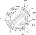
- the flow path member 110includes an outer cylinder 111 and an inner member 112.
- the outer cylinder 111is configured in a tubular shape extending in the pipe axial direction Ds connecting one end 1101 and the other end 1102 of the flow path member 110.
- the outer cylinder 111has, for example, a circular cross-sectional shape as seen from the pipe axial direction Ds.
- the cross-sectional shape of the outer cylinder 111 as viewed from the pipe axial direction Dsmay be, for example, an ellipse.
- the cross-sectional shape of the outer cylinder 111 as viewed from the pipe axis direction Dsmay be a polygon such as a triangle, a quadrangle, a pentagon, a hexagon, or an octagon.
- the inner member 112is inserted inside the outer cylinder 111.
- the inner member 112is formed in a columnar shape extending in the pipe axis direction Ds.
- the inner member 112has the same cross-sectional shape in the pipe axial direction Ds.
- the inner member 112has a plurality of grooves 1121 extending in the pipe axial direction Ds.
- the plurality of grooves 1121are arranged at equal intervals in the circumferential direction around the central axis of the inner member 112.
- Each groove 1121is recessed radially inward from the outer peripheral surface 1122 of the inner member 112.
- Each groove 1121extends continuously in the pipe axial direction Ds.
- the outer peripheral surface 1122 of the inner member 112 inserted into the outer cylinder 111is in contact with or close to the inner peripheral surface 1111 of the outer cylinder 111 with a slight gap.
- the flow path 113is defined between the inner peripheral surface 1111 of the outer cylinder 111 and each groove 1121 of the inner member 112.
- the flow path 113extends in the pipe axial direction Ds and penetrates the one end 1101 and the other end 1102 of the flow path member 110.
- the flow path member 110has a plurality of flow paths 113.
- the plurality of flow paths 113extend in the pipe axial direction Ds connecting one end 1101 and the other end 1102.
- the plurality of flow paths 113are arranged substantially parallel to each other.
- the contact member 120is arranged at one end 1101 of the flow path member 110.
- the contact member 120is configured to come into contact with an object that collects the liquid.
- the contact member 120may include an elastic material or may be an elastic material. When the contact member 120 contains an elastic material, the contact member 120 may be a combination of a portion formed of the elastic material and a portion formed of another material.
- the contact member 120has a flow path member insertion hole 121.
- the flow path member insertion hole 121extends in the pipe axial direction Ds.
- the flow path member insertion hole 121has an inlet opening 1211 at one end of the pipe axial direction Ds.
- the inlet opening 1211opens on the side opposite to the side where the flow path member 110 is arranged in the pipe axis direction Ds.
- the inlet opening 1211is configured to contact the surface of the liquid to be collected and take in the liquid located at or near the surface.
- the flow path member insertion hole 121has an outlet opening 1212 at the other end of the pipe axial direction Ds.
- the outlet opening 1212opens on the side where the flow path member 110 is arranged in the pipe axis direction Ds.
- the outlet opening 1212is fluidly connected to the inlet opening 1211 through the flow path member insertion hole 121.
- One end 1101 of the flow path member 110is fitted into the outlet opening 1212 of the contact member 120 from the other side in the pipe axial direction Ds.
- One end 1101 of the flow path member 110is arranged at a position recessed on the other side of the pipe axial direction Ds from the inlet opening 1211 of the contact member 120.
- One end 1101 of the flow path member 110does not project from the contact member 120 to one side of the pipe axial direction Ds. In this way, the outlet opening 1212 is fluidly connected to the flow path member 110.
- the contact member 120has a contact surface 123 around the inlet opening 1211.
- the contact surface 123is formed on the entire rest of the contact member 120 except for the side facing the container 130 on the other side in the tube axial direction Ds.
- the contact surface 123is configured to be in contact with the surface of the liquid to be collected.
- the contact surface 123protrudes from one end 1101 of the flow path member 110 to one side of the pipe axial direction Ds. At least a part of the contact surface 123 is formed in a spherical shape.
- the container 130accommodates the liquid discharged from the flow path 113 at the other end 1102 of the flow path member 110.
- the container 130integrally has a peripheral wall 131 and a bottom portion 132.
- the peripheral wall 131is configured in a cylindrical shape extending in the pipe axis direction Ds.
- the peripheral wall 131is formed with a constant diameter in the pipe axial direction Ds.
- the inner diameter of the peripheral wall 131is larger than the outer diameter of the flow path member 110.
- the inner peripheral surface of the peripheral wall 131 and the outer peripheral surface of the flow path member 110are arranged at intervals in the radial direction orthogonal to the pipe axis direction Ds.
- the bottom 132closes the peripheral wall 131 on the other side of the pipe axial direction Ds.
- the bottom 132is formed, for example, in a hemispherical shape.
- the bottom portion 132may have a plate shape arranged in a plane substantially orthogonal to the pipe axis direction Ds.
- the container 130is formed in a bottomed cylindrical shape by including a peripheral wall 131 and a bottom portion 132.
- the container 130has an opening 133 on one side (opposite side of the bottom 132) of the pipe axial direction Ds.
- the contact member 120is arranged so as to close the opening 133 of the container 130.
- the bottom 132 of the container 130is arranged between the bottom 132 of the flow path member 110 and the other end 1102 in the pipe axis direction Ds.
- a storage space 138 for storing the liquidis defined between the bottom 132 of the container 130 and the other end 1102 of the flow path member 110.
- At least a part or all of the container 130may be made of a transparent material whose inside can be optically confirmed from the outside of the container 130.
- the transparent material whose inside can be optically confirmed from the outside of the container 130may be, for example, a resin-based material or a glass-based material without limitation.
- the transparent material that allows the inside of the container 130 to be optically confirmed from the outsideso that the amount of liquid accumulated inside the container body can be visually confirmed or visually confirmed by a camera from the outside of the container 130. You may do it.
- the container 130is formed with a scale 139 indicating the amount of liquid contained in the container 130.
- the inlet opening 1211 of the contact member 120is brought into contact with the surface of the liquid collection target.
- the liquid collector 100collects body fluid (liquid) secreted by the subject.
- the location where the subject's body fluid is secretedis, for example, but not limited to, the eyeball, the outer or inner corner of the eye, the oral cavity (eg, sublingual), the nasal cavity, and the skin surface.
- the liquid collector 100collects tears as a liquid from the outer corners of the eyes of the subject. In this case, as shown in FIG.
- the entrance opening 1211 of the contact member 120is brought into contact with the outer corner of the eye of the subject or the surface 1000 of the face in the vicinity of the outer corner of the eye.
- the liquid 999 located at or near the surface 1000is taken in from the inlet opening 1211 by the capillary phenomenon.
- the liquid 999 (tear liquid) located at or near the surface 1000is taken in from the inlet opening 1211.
- the liquid 999 taken into the inlet opening 1211flows from one end 1101 of the flow path member 110 into the flow path 113, travels through the flow path 113, and flows to the other end 1102 side.
- the liquid 999is discharged from the flow path 113 at the other end 1102 of the flow path member 110.
- the liquid 999 discharged from the flow path 113is stored in the storage space 138 in the container 130. In this way, the liquid can be efficiently collected.
- the liquid 999When collecting the liquid 999, if the pipe axial direction Ds of the liquid collector 100 is tilted with respect to the vertical direction Dv, the liquid 999 flows to the lower side of the vertical direction Dv at the inlet opening 1211. The liquid 999 easily flows from the inlet opening 1211 into the flow path 113d located on the lower side of the vertical direction Dv among the plurality of flow paths 113 of the flow path member 110.
- the liquid 999flows into the storage space 138, the volume of air of the liquid 999 that has flowed in is pushed out from the storage space 138.
- the air extruded from the storage space 138moves to the inlet opening 1211 side through the flow path 113 in which the liquid 999 does not flow, for example, located above the vertical direction Dv among the plurality of flow paths 113.
- the liquid collector 200includes a flow path member 210, a contact member 220, and a container 230.
- the liquid collector 200collects liquid.
- the flow path member 210includes an outer cylinder 211 and an inner member 212.
- the outer cylinder 211is configured in a tubular shape extending in the pipe axial direction Ds connecting one end 2101 and the other end 2102 of the flow path member 210.
- the outer cylinder 211has, for example, a circular cross-sectional shape as seen from the pipe axial direction Ds.
- the cross-sectional shape of the outer cylinder 211 as viewed from the pipe axial direction Dsmay be, for example, an ellipse.
- the cross-sectional shape of the outer cylinder 211 as viewed from the pipe axis direction Dsmay be a polygon such as a triangle, a quadrangle, a pentagon, a hexagon, or an octagon.
- the inner member 212is inserted inside the outer cylinder 211.
- the inner member 212is formed in a columnar shape extending in the pipe axis direction Ds.
- the inner member 212has the same cross-sectional shape in the pipe axial direction Ds.
- the inner member 212has a plurality of grooves 2121 extending in the pipe axial direction Ds.
- the plurality of grooves 2121are arranged at equal intervals in the circumferential direction around the central axis of the inner member 212.
- Each groove 2121is recessed inward in the radial direction from the outer peripheral surface 2122 of the inner member 212.
- Each groove 2121extends continuously in the pipe axial direction Ds.
- the outer peripheral surface 2122 of the inner member 212 inserted into the outer cylinder 211is in contact with or close to the inner peripheral surface 2111 of the outer cylinder 211 with a slight gap.
- a flow path 213is defined between the inner peripheral surface 2111 of the outer cylinder 211 and each groove 2121 of the inner member 212.
- the flow path 213extends in the pipe axial direction Ds and penetrates the one end 2101 and the other end 2102 of the flow path member 210.
- the flow path member 210has a plurality of flow paths 213.
- the plurality of flow paths 213extend in the pipe axial direction Ds connecting one end 2101 and the other end 2102.
- the plurality of flow paths 213are arranged substantially parallel to each other.
- the contact member 220is arranged at one end 2101 of the flow path member 210.
- the contact member 220is configured to come into contact with an object that collects the liquid.
- the contact member 220may contain an elastic material or may be an elastic material. When the contact member 220 contains an elastic material, the contact member 220 may be a combination of a portion formed of the elastic material and a portion formed of another material.
- the contact member 220has a flow path member insertion hole 221.
- the flow path member insertion hole 221extends in the pipe axial direction Ds.
- the flow path member insertion hole 221has an inlet opening 2211 at one end of the pipe axial direction Ds.
- the inlet opening 2211opens on the side opposite to the side where the flow path member 210 is arranged in the pipe axis direction Ds.
- the inlet opening 2211is configured to contact the surface of the liquid collection target and take in the liquid located at or near the surface.
- the flow path member insertion hole 221has an outlet opening 2212 at the other end of the pipe axial direction Ds.
- the outlet opening 2212opens on the side where the flow path member 210 is arranged in the pipe axis direction Ds.
- the outlet opening 2212is fluidly connected to the inlet opening 2211 through the flow path member insertion hole 221.
- One end 2101 of the flow path member 210is fitted into the outlet opening 2212 of the contact member 220 from the other side in the pipe axial direction Ds.
- One end 2101 of the flow path member 210is arranged at a position recessed on the other side of the pipe axial direction Ds from the inlet opening 2211 of the contact member 220.
- One end 2101 of the flow path member 210does not project from the contact member 220 to one side of the pipe axial direction Ds. In this way, the outlet opening 2212 is fluidly connected to the flow path member 210.
- the contact member 220has a contact surface 223 around the inlet opening 2211.
- the contact surface 223is configured to come into contact with the surface of the liquid to be collected.
- the contact surface 223projects from one end 2101 of the flow path member 210 to one side of the pipe axial direction Ds. At least a part of the contact surface 223 is formed in a spherical shape. The entire remaining portion of the contact surface 223 is formed in a spherical shape except for the side of the contact member 220 that faces the container 230 on the other side in the tube axial direction Ds.
- the container 230houses the liquid discharged from the flow path 213 at the other end 2102 of the flow path member 210.
- the container 230integrally has a peripheral wall 231 and a bottom portion 232.
- the peripheral wall 231is configured in a cylindrical shape extending in the pipe axis direction Ds.
- the peripheral wall 231is formed with a constant diameter in the pipe axial direction Ds.
- the inner diameter of the peripheral wall 231is substantially the same as the outer diameter of the flow path member 210.
- the other end 2102 of the flow path member 210is in contact with the inner peripheral surface 2314 of the peripheral wall 231.
- the liquid in the flow path 213 of the flow path member 210is transmitted to the inner peripheral surface 2314 of the peripheral wall 231 and moves. It will be easier to do.
- the bottom portion 232closes the peripheral wall 231 on the other side of the pipe axial direction Ds.
- the bottom 232is formed, for example, in a hemispherical shape.
- the bottom portion 232may have a plate shape arranged in a plane substantially orthogonal to the pipe axial direction Ds.
- the container 230is formed in a bottomed cylindrical shape by including a peripheral wall 231 and a bottom portion 232.
- the container 230has an opening 233 on one side (opposite side of the bottom 232) of the pipe axial direction Ds.
- the contact member 220is arranged so as to close the opening 233 of the container 230.
- the bottom portion 232 of the container 230is arranged between the bottom portion 232 and the other end 2102 of the flow path member 210 at intervals in the pipe axis direction Ds.
- a storage space 238 for storing the liquidis defined between the bottom 232 of the container 230 and the other end 2102 of the flow path member 210.
- At least a part or all of the container 230may be made of a transparent material whose inside can be optically confirmed from the outside of the container 230.
- the transparent material whose inside can be optically confirmed from the outside of the container 230may be, for example, a resin-based material or a glass-based material without limitation.
- the transparent material that allows the inside of the container 230 to be optically confirmed from the outsideso that the amount of liquid accumulated inside the container body can be visually confirmed or visually confirmed by a camera from the outside of the container 230. You may do it.
- the container 230is formed with a scale 239 indicating the amount of liquid contained in the container 230.
- the inlet opening 2211 of the contact member 220is brought into contact with the surface 1000 of the liquid collection target.
- the liquid 999 located at or near the surface 1000is taken in from the inlet opening 2211 by the capillary phenomenon.
- the liquid 999 taken into the inlet opening 2211flows into the flow path 213 from one end 2101 of the flow path member 210.
- the liquid 999flows through the flow path 213 and flows toward the other end 2102 side.
- the liquid 999is discharged from the flow path 213 at the other end 2102 of the flow path member 210.
- the liquid 999 discharged from the flow path 213is easily transmitted to the inner peripheral surface 2314 of the container 230.
- the liquid 999flows downward along the inner peripheral surface 2314 and is stored in the storage space 238 in the container 230. In this way, the liquid can be efficiently collected.
- the liquid 999When collecting the liquid 999, if the pipe axial direction Ds of the liquid collector 200 is tilted with respect to the vertical direction Dv, the liquid 999 flows to the lower side of the vertical direction Dv at the inlet opening 2211. The liquid 999 easily flows from the inlet opening 2211 into the flow path 213d located on the lower side of the vertical direction Dv among the plurality of flow paths 213 of the flow path member 210.
- the air corresponding to the volume of the flowing liquid 999is pushed out from the storage space 238.
- the air extruded from the storage space 238is located above the vertical Dv among the plurality of flow paths 213, and is discharged to the outside from the inlet opening 2211 through the flow path 213 through which the liquid 999 does not flow.
- the liquid collector 300includes a flow path member 310, a contact member 320, a container 330, and an inner member 340.
- the liquid collector 300collects the liquid.
- the flow path member 310includes an outer cylinder 311 and an inner member 312.
- the outer cylinder 311is configured in a tubular shape extending in the pipe axial direction Ds connecting one end 3101 and the other end 3102 of the flow path member 310.
- the outer cylinder 311has, for example, a circular cross-sectional shape as seen from the pipe axial direction Ds.
- the cross-sectional shape of the outer cylinder 311 as viewed from the pipe axial direction Dsmay be, for example, an elliptical shape.
- the cross-sectional shape of the outer cylinder 311 as viewed from the pipe axis direction Dsmay be a polygon such as a triangle, a quadrangle, a pentagon, a hexagon, or an octagon.
- the inner member 312is inserted inside the outer cylinder 311.
- the inner member 312is formed in a columnar shape extending in the pipe axis direction Ds.
- the inner member 312has the same cross-sectional shape in the pipe axial direction Ds.
- the inner member 312has a plurality of grooves 3121 extending in the pipe axial direction Ds.
- the plurality of grooves 3121are arranged at equal intervals in the circumferential direction around the central axis of the inner member 312.
- Each groove 3121is recessed inward in the radial direction from the outer peripheral surface 3122 of the inner member 312.
- Each groove 3121extends continuously in the pipe axial direction Ds.
- the outer peripheral surface 3122 of the inner member 312 inserted into the outer cylinder 311is in contact with or close to the inner peripheral surface 3111 of the outer cylinder 311 with a slight interval.
- a flow path 313is defined between the inner peripheral surface 3111 of the outer cylinder 311 and each groove 3121 of the inner member 312.
- the flow path 313extends in the pipe axial direction Ds and penetrates the one end 3101 and the other end 3102 of the flow path member 310.
- the flow path member 310has a plurality of flow paths 313.
- the plurality of flow paths 313extend in the pipe axial direction Ds connecting one end 3101 and the other end 3102.
- the plurality of flow paths 313are arranged substantially parallel to each other.
- the contact member 320is arranged at one end 3101 of the flow path member 310.
- the contact member 320is configured to come into contact with an object that collects the liquid.
- the contact member 320may include an elastic material or may be an elastic material. When the contact member 320 contains an elastic material, the contact member 320 may be a combination of a portion formed of the elastic material and a portion formed of another material.
- the contact member 320has a flow path member insertion hole 321.
- the flow path member insertion hole 321extends in the pipe axial direction Ds.
- the flow path member insertion hole 321has an inlet opening 3211 at one end of the pipe axial direction Ds.
- the inlet opening 3211opens on the side opposite to the side where the flow path member 310 is arranged in the pipe axis direction Ds.
- the inlet opening 3211is configured to contact the surface of the liquid collection target and take in the liquid located at or near the surface.
- the flow path member insertion hole 321has an outlet opening 3212 at the other end of the pipe axial direction Ds.
- the outlet opening 3212opens on the side where the flow path member 310 is arranged in the pipe axial direction Ds.
- the outlet opening 3212is fluidly connected to the inlet opening 3211 through the flow path member insertion hole 321.
- One end 3101 of the flow path member 310is fitted into the outlet opening 3212 of the contact member 320 from the other side in the pipe axial direction Ds.
- One end 3101 of the flow path member 310is arranged at a position recessed on the other side of the pipe axial direction Ds from the inlet opening 3211 of the contact member 320.
- One end 3101 of the flow path member 310does not project from the contact member 320 to one side of the pipe axial direction Ds. In this way, the outlet opening 3212 is fluidly connected to the flow path member 310.
- the contact member 320has a contact surface 323 around the inlet opening 3211.
- the contact surface 323is configured to be in contact with the surface of the liquid to be collected.
- the contact surface 323projects to one side of the pipe axial direction Ds from one end 3101 of the flow path member 310. At least a part of the contact surface 323 is formed in a spherical shape. The entire remaining portion of the contact surface 323 is formed in a spherical shape except for the side of the contact member 320 that faces the container 330 on the other side in the tube axial direction Ds.
- the container 330accommodates the liquid discharged from the flow path 313 at the other end 3102 of the flow path member 310.
- the container 330integrally has a peripheral wall 331 and a bottom portion 332.
- the peripheral wall 331is configured in a cylindrical shape extending in the pipe axis direction Ds.
- the inner diameter of the peripheral wall 331gradually decreases from one side to the bottom 332 on the other side in the pipe axis direction Ds.
- the bottom portion 332closes the peripheral wall 331 on the other side of the pipe axial direction Ds.
- the bottom portion 332is formed, for example, in a hemispherical shape.
- the bottom portion 332may have a plate shape arranged in a plane substantially orthogonal to the pipe axial direction Ds.
- the container 330is formed in a bottomed cylindrical shape by including a peripheral wall 331 and a bottom portion 332.
- the container 330has an opening 333 on one side (opposite side of the bottom 332) of the pipe axial direction Ds.
- the contact member 320is arranged so as to close the opening 333 of the container 330.
- the bottom portion 332 of the container 330is arranged between the bottom portion 332 of the flow path member 310 and the other end 3102 at intervals in the pipe axis direction Ds.
- a storage space 338 for storing the liquidis defined between the bottom portion 332 of the container 330 and the other end 3102 of the flow path member 310.
- At least a part or all of the container 330may be made of a transparent material whose inside can be optically confirmed from the outside of the container 330.
- the transparent material whose inside can be optically confirmed from the outside of the container 330may be, for example, a resin-based material or a glass-based material without limitation.
- the transparent material that allows the inside of the container 330 to be optically confirmed from the outsideso that the amount of liquid accumulated inside the container body can be visually confirmed or visually confirmed by a camera from the outside of the container 330. You may do it.
- the container 330is formed with a scale 339 indicating the amount of liquid contained in the container 330.
- the inner member 340is arranged inside the container 330.
- the inner member 340has a cone-shaped portion 341 whose inner diameter gradually decreases toward the bottom portion 332 side in the pipe axial direction Ds.
- the cone-shaped portion 341is formed over the entire tube axial direction Ds of the inner member 340.
- the cone-shaped portion 341may be formed only on a part of the tube axial Ds of the inner member 340.
- the cone-shaped portion 341is configured such that the inner diameter of the first opening 3411 on the opening 333 side is larger than the outer diameter of the other end 3102 of the flow path member 310.
- the inner diameter of the second opening 3412 on the bottom 332 side of the cone-shaped portion 341is smaller than the outer diameter of the other end 3102 of the flow path member 310.
- the other end 3102 of the flow path member 310is in contact with the inner peripheral surface of the cone-shaped portion 341 between the first opening 3411 and the second opening 3412 of the cone-shaped portion 341.
- the liquid in the flow path 313 of the flow path member 310is easily transmitted to the inner peripheral surface of the cone-shaped portion 341 and easily moves.
- the inlet opening 3211 of the contact member 320is brought into contact with the surface 1000 of the liquid collection target.
- the liquid 999 located at or near the surface 1000is taken in from the inlet opening 3211 by the capillary phenomenon.
- the liquid 999 taken into the inlet opening 3211flows into the flow path 313 from one end 3101 of the flow path member 310.
- the liquid 999flows through the flow path 313 and flows toward the other end 3102 side.
- the liquid 999is discharged from the flow path 313 at the other end 3102 of the flow path member 310.
- the liquid 999 discharged from the flow path 313flows downward along the inner peripheral surface of the cone-shaped portion 341.
- the liquid 999falls from the second opening 3412 of the cone-shaped portion 341 into the storage space 338 in the container 330 and is stored. In this way, the liquid can be efficiently collected.
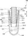
- the liquid collector 400includes a flow path member 410, a contact member 420, a container 430, and an inner member 440.
- the liquid collector 400collects the liquid.
- the flow path member 410includes an outer cylinder 411 and an inner member 412.
- the outer cylinder 411is configured in a tubular shape extending in the pipe axial direction Ds connecting one end 4101 and the other end 4102 of the flow path member 410.
- the outer cylinder 411has, for example, a circular cross-sectional shape as seen from the pipe axial direction Ds.
- the cross-sectional shape of the outer cylinder 411 as viewed from the pipe axial direction Dsmay be, for example, an elliptical shape.
- the cross-sectional shape of the outer cylinder 411 as viewed from the pipe axis direction Dsmay be a polygon such as a triangle, a quadrangle, a pentagon, a hexagon, or an octagon.
- the inner member 412is inserted inside the outer cylinder 411.
- the inner member 412is formed in a columnar shape extending in the pipe axis direction Ds.
- the inner member 412has the same cross-sectional shape in the pipe axial direction Ds.
- the inner member 412has a plurality of grooves 4121 extending in the pipe axial direction Ds.
- the plurality of grooves 4121are arranged at equal intervals in the circumferential direction around the central axis of the inner member 412.
- Each groove 4121is recessed inward in the radial direction from the outer peripheral surface 4122 of the inner member 412.
- Each groove 4121extends continuously in the pipe axial direction Ds.
- the outer peripheral surface 4122 of the inner member 412 inserted into the outer cylinder 411is in contact with or close to the inner peripheral surface 4111 of the outer cylinder 411 with a slight gap.
- a flow path 413is defined between the inner peripheral surface 4111 of the outer cylinder 411 and each groove 4121 of the inner member 412.
- the flow path 413extends in the pipe axial direction Ds and penetrates the one end 4101 and the other end 4102 of the flow path member 410.
- the flow path member 410has a plurality of flow paths 413.
- the plurality of flow paths 413extend in the pipe axial direction Ds connecting one end 4101 and the other end 4102.
- the plurality of flow paths 413are arranged substantially parallel to each other.
- the contact member 420is arranged at one end 4101 of the flow path member 410.
- the contact member 420is configured to come into contact with an object that collects the liquid.
- the contact member 420may include an elastic material or may be an elastic material. When the contact member 420 contains an elastic material, the contact member 420 may be a combination of a portion formed of the elastic material and a portion formed of another material.
- the contact member 420has a flow path member insertion hole 421.
- the flow path member insertion hole 421extends in the pipe axial direction Ds.
- the flow path member insertion hole 421has an inlet opening 4211 at one end of the pipe axial direction Ds.
- the inlet opening 4211opens on the side opposite to the side where the flow path member 410 is arranged in the pipe axis direction Ds.
- the inlet opening 4211is configured to contact the surface of the liquid collection target and take in the liquid located at or near the surface.
- the contact member 420integrally includes a sleeve 425.
- the sleeve 425projects from the contact member 420 toward the other end 4102 of the flow path member 410.
- the sleeve 425extends in the tube axial direction Ds.
- the sleeve 425is inserted into the container 430.
- the flow path member insertion hole 421has an outlet opening 4212 at the other end of the pipe axial direction Ds.
- the outlet opening 4212is formed in the sleeve 425.
- the outlet opening 4212opens on the side where the flow path member 410 is arranged in the pipe axis direction Ds.
- the outlet opening 4212is fluidly connected to the inlet opening 4211 through the flow path member insertion hole 421.
- One end 4101 of the flow path member 410is fitted into the outlet opening 4212 of the contact member 420 from the other side in the pipe axial direction Ds. Since the contact member 420 has a sleeve 425, one end 4101 of the flow path member 410 is held by the contact member 420 (including the sleeve 425) in a portion having a longer dimension in the pipe axial direction Ds. As a result, the flow path member 410 is supported more firmly. In this way, the outlet opening 4212 is fluidly connected to the flow path member 410.
- One end 4101 of the flow path member 410is arranged at a position recessed on the other side of the pipe axial direction Ds from the inlet opening 4211 of the contact member 420.
- One end 4101 of the flow path member 410does not project from the contact member 420 to one side of the pipe axial direction Ds.
- the contact member 420has a contact surface 423 around the inlet opening 4211.
- the contact surface 423is configured to be in contact with the surface of the liquid to be collected.
- the contact surface 423projects to one side of the pipe axial direction Ds from one end 4101 of the flow path member 410. At least a part of the contact surface 423 is formed in a spherical shape. The entire remaining portion of the contact surface 423 is formed in a spherical shape except for the side of the contact member 420 facing the container 430 on the other side in the tube axial direction Ds.
- the container 430accommodates the liquid discharged from the flow path 413 at the other end 4102 of the flow path member 410.
- the container 430integrally has a peripheral wall 431 and a bottom portion 432.
- the peripheral wall 431is configured in a cylindrical shape extending in the pipe axis direction Ds.
- the inner diameter of the peripheral wall 431gradually decreases from one side to the bottom 432 on the other side in the pipe axis direction Ds.
- the bottom portion 432closes the peripheral wall 431 on the other side of the pipe axial direction Ds.
- the bottom 432is formed, for example, in a hemispherical shape.
- the bottom portion 432may have a plate shape arranged in a plane substantially orthogonal to the tube axial direction Ds.
- the container 430is formed in a bottomed cylindrical shape by including a peripheral wall 431 and a bottom portion 432.
- the container 430has an opening 433 on one side (opposite the bottom 432) of the pipe axial direction Ds, and the contact member 420 is arranged so as to close the opening 433 of the container 430.
- the bottom portion 432 of the container 430is arranged between the bottom portion 432 of the flow path member 410 and the other end 4102 in the pipe axis direction Ds at intervals.
- a storage space 438 for storing the liquidis defined between the bottom 432 of the container 430 and the other end 4102 of the flow path member 410.
- At least a part or all of the container 430may be made of a transparent material whose inside can be optically confirmed from the outside of the container 430.
- the transparent material whose inside can be optically confirmed from the outside of the container 430may be, for example, a resin-based material or a glass-based material without limitation.
- the transparent material that allows the inside of the container 430 to be optically confirmed from the outsideso that the amount of liquid accumulated inside the container body can be visually confirmed or visually confirmed by a camera from the outside of the container 430. You may do it.
- the container 430is formed with a scale 439 indicating the amount of liquid contained in the container 430.
- the inner member 440is arranged inside the container 430.
- the inner member 440has a cone-shaped portion 441 whose inner diameter gradually decreases toward the bottom portion 432 side in the pipe axial direction Ds.
- the cone-shaped portion 441is formed over the entire tube axial direction Ds of the inner member 440.
- the cone-shaped portion 441may be formed only on a part of the tube axial Ds of the inner member 440.
- the cone-shaped portion 441is configured such that the inner diameter of the first opening 4411 on the opening 433 side is larger than the outer diameter of the other end 4102 of the flow path member 410.
- the inner diameter of the second opening 4412 on the bottom 432 side of the cone-shaped portion 441is smaller than the outer diameter of the other end 4102 of the flow path member 410.
- the other end 4102 of the flow path member 410is in contact with the inner peripheral surface of the cone-shaped portion 441 between the first opening 4411 and the second opening 4412 of the cone-shaped portion 441.
- the liquid in the flow path 413 of the flow path member 410is easily transmitted to the cone-shaped portion 441 and moves easily.
- the inlet opening 4211 of the contact member 420is brought into contact with the surface 1000 of the liquid collection target.
- the liquid 999 located at or near the surface 1000is taken in from the inlet opening 4211 by the capillary phenomenon.
- the liquid 999 taken into the inlet opening 4211flows into the flow path 413 from one end 4101 of the flow path member 410.
- the liquid 999flows through the flow path 413 and flows to the other end 4102 side.
- the liquid 999is discharged from the flow path 413 at the other end 4102 of the flow path member 410.
- the liquid 999 discharged from the flow path 413flows downward along the inner peripheral surface of the cone-shaped portion 441.
- the liquid 999falls from the second opening 4412 of the cone-shaped portion 441 into the storage space 438 in the container 430 and is stored. In this way, the liquid can be efficiently collected.
- the liquid collector 500includes a flow path member 510, a container 530, and an inner member 540.
- the liquid collector 500collects the liquid.
- the flow path member 510includes an outer cylinder 511 and an inner member 512.
- the outer cylinder 511is configured in a tubular shape extending in the pipe axial direction Ds connecting one end 5101 and the other end 5102 of the flow path member 510.
- the outer cylinder 511has, for example, a circular cross-sectional shape as seen from the pipe axial direction Ds.
- the cross-sectional shape of the outer cylinder 511 as viewed from the pipe axial direction Dsmay be, for example, an elliptical shape.
- the cross-sectional shape of the outer cylinder 511 as viewed from the pipe axis direction Dsmay be a polygon such as a triangle, a quadrangle, a pentagon, a hexagon, or an octagon.
- the inner member 512is inserted inside the outer cylinder 511.
- the inner member 512is formed in a columnar shape extending in the pipe axis direction Ds.
- the inner member 512has the same cross-sectional shape in the pipe axial direction Ds.
- the inner member 512has a plurality of grooves 5121 extending in the pipe axial direction Ds.
- the plurality of grooves 5121are arranged at equal intervals in the circumferential direction around the central axis of the inner member 512.
- Each groove 5121is recessed inward in the radial direction from the outer peripheral surface 5122 of the inner member 512.
- Each groove 5121extends continuously in the pipe axial direction Ds.
- the outer peripheral surface 5122 of the inner member 512 inserted into the outer cylinder 511is in contact with or close to the inner peripheral surface 5111 of the outer cylinder 511 with a slight gap.
- a flow path 513is defined between the inner peripheral surface 5111 of the outer cylinder 511 and each groove 5121 of the inner member 512.
- the flow path 513extends in the pipe axial direction Ds and penetrates the one end 5101 and the other end 5102 of the flow path member 510.
- the flow path member 510has a plurality of flow paths 513.
- the plurality of flow paths 513extend in the pipe axial direction Ds connecting one end 5101 and the other end 5102.
- the plurality of flow paths 513are arranged substantially parallel to each other.
- the container 530accommodates the liquid discharged from the flow path 513 at the other end 5102 of the flow path member 510.
- the container 530integrally has a peripheral wall 531 and a bottom portion 532.
- the peripheral wall 531is configured in a cylindrical shape extending in the pipe axis direction Ds.
- the inner diameter of the peripheral wall 531gradually decreases from one side to the bottom 532 on the other side in the pipe axis direction Ds.
- the bottom portion 532closes the peripheral wall 531 on the other side of the pipe axial direction Ds.
- the bottom 532is formed, for example, in a hemispherical shape.
- the bottom portion 532may have a plate shape arranged in a plane substantially orthogonal to the tube axial direction Ds.
- the container 530is formed in a bottomed cylindrical shape by including a peripheral wall 531 and a bottom portion 532.
- the container 530has an opening 533 on one side (opposite side of the bottom 532) of the pipe axial direction Ds.
- the flow path member 510is inserted into the container 530 through the opening 533.
- the bottom portion 532 of the container 530is arranged at a distance from the other end 5102 of the flow path member 510 in the pipe axial direction Ds.
- a storage space 538 for storing the liquidis defined between the bottom portion 532 of the container 530 and the other end 5102 of the flow path member 510.
- At least a part or all of the conditioned container 530may be made of a transparent material whose inside can be optically confirmed from the outside of the container 530.
- the transparent material whose inside can be optically confirmed from the outside of the container 530may be, for example, a resin-based material or a glass-based material without limitation.
- the transparent material that allows the inside of the container 530 to be optically confirmed from the outsideso that the amount of liquid accumulated inside the container body can be visually confirmed or visually confirmed by a camera from the outside of the container 530. You may do it.
- the container 530is formed with a scale 539 indicating the amount of liquid contained in the container 530.
- the inner member 540is arranged inside the container 530.
- the inner member 540has a cone-shaped portion 541 whose inner diameter gradually decreases toward the bottom portion 532 in the pipe axial direction Ds.
- the cone-shaped portion 541is formed over the entire tube axial direction Ds of the inner member 540.
- the cone-shaped portion 541may be formed only on a part of the tube axial Ds of the inner member 540.
- the cone-shaped portion 541is configured such that the inner diameter of the first opening 5411 on the opening 533 side is larger than the outer diameter of the other end 5102 of the flow path member 510.
- the inner diameter of the second opening 5412 on the bottom 532 side of the cone-shaped portion 541is smaller than the outer diameter of the other end 5102 of the flow path member 510.
- the other end 5102 of the flow path member 510is in contact with the inner peripheral surface of the cone-shaped portion 541 between the first opening 5411 and the second opening 5412 of the cone-shaped portion 541.
- the liquid in the flow path 513 of the flow path member 510is easily transmitted to the cone-shaped portion 541 and moves easily.
- one end 5101 of the flow path member 510is brought into contact with the surface 1000 of the liquid collection target.
- the surface of the one end 5101may have hydrophilicity or may be textured.
- the liquid 999 located at or near the surface 1000is taken in from one end 5101 of the flow path member 510 by the capillary phenomenon.
- the liquid 999 taken into the flow path member 510travels through the plurality of flow paths 513 and flows to the other end 5102 side.
- the liquid 999is discharged from the flow path 513 at the other end 5102 of the flow path member 510.
- the liquid 999 discharged from the flow path 513flows downward along the inner peripheral surface of the cone-shaped portion 541.
- the liquid 999falls from the second opening 5412 of the cone-shaped portion 541 into the storage space 538 in the container 530 and is stored. In this way, the liquid can be efficiently collected.
- FIG. 12shows a flow path member 710 of the liquid collector according to a certain embodiment.
- the flow path member 710is configured in a columnar shape extending in the pipe axial direction Ds (direction orthogonal to the paper surface of FIG. 12) connecting one end and the other end.
- the flow path member 710has, for example, a circular cross-sectional shape as seen from the pipe axial direction Ds.
- the cross-sectional shape of the flow path member 710 as viewed from the pipe axial direction Dsmay be, for example, an elliptical shape.
- the cross-sectional shape of the flow path member 710 as viewed from the pipe axis direction Dsmay be a polygon such as a triangle, a quadrangle, a pentagon, a hexagon, or an octagon.
- the flow path member 710has a plurality of through holes 715 extending in the pipe axial direction Ds and connecting one end and the other end inside the flow path member 710.
- the through hole 715A of one of the plurality of through holes 715is arranged at the center of the flow path member 710.
- the remaining other through holes 715Bare arranged on the outer peripheral portion of the flow path member 710 at equal intervals in the circumferential direction.
- the plurality of through holes 715are arranged substantially parallel to the pipe axial direction Ds.
- Each through hole 715forms a liquid flow path 713 in the flow path member 710.
- the flow path member 710has a plurality of flow path 713s (through holes 715).
- the plurality of flow paths 713extend in the pipe axial direction Ds connecting one end and the other end.
- the plurality of flow paths 713are arranged substantially parallel to each other.
- such a flow path member 710may be used in place of the flow path members 110, 210, 310, 410, 510.
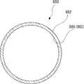
- FIG. 13shows a flow path member 810 of the liquid collector according to a certain embodiment.
- the flow path member 810includes a plurality of single tubes 812.
- Each single tube 812is formed in a cylindrical shape extending in the tube axial direction Ds (direction orthogonal to the paper surface in FIG. 13).
- the single pipe 812has the same cross-sectional shape in the pipe axial direction Ds.
- the single tube 812has, for example, a circular cross-sectional shape as seen from the tube axial direction Ds.
- the flow path member 810is formed by bundling a plurality of single tubes 812.
- the plurality of single tubes 812may be integrally bundled and joined, for example, without limitation, by adhesion, welding, welding, or the like.
- the plurality of single tubes 812may be bundled into one, for example, without limitation, by a band-shaped band, a ring, or the like.
- the cross-sectional shape of the single tubemay vary in the direction of the tube axis.
- the single tubemay be configured by combining two single tubes having different sizes (for example, hole diameter).
- the single tube 812Awhich is one of the plurality of single tubes 812, is arranged at the center of the flow path member 810. Of the plurality of single tubes 812, the remaining single tube 812B is arranged on the radial outer side of the single tube 812A so as to be in contact with each other in the circumferential direction.
- Each single tube 812extends continuously in the tube axial direction Ds. Inside each single pipe 812, a hole 815 penetrating in the pipe axial direction Ds is formed.
- a plurality of gaps 816are formed between the single tube 812A and the plurality of single tubes 812B arranged on the outer side in the radial direction thereof.
- Each gap 816is continuous in the pipe axial direction Ds and penetrates one end and the other end of the flow path member 810.
- a plurality of holes 815 and a plurality of gaps 816are defined in the flow path member 810.
- the holes 815 and the gaps 816each form a liquid flow path 813 in the flow path member 810.
- the flow path member 810has a plurality of flow paths 813 (flow path 813 and gap 816).
- the plurality of flow paths 813extend in the pipe axial direction Ds connecting one end and the other end of the flow path member 810.
- the plurality of flow paths 813are arranged substantially parallel to each other.
- such a flow path member 810may be used in place of the flow path members 110, 210, 310, 410, 510.
- FIG. 14shows a flow path member 910 of a liquid collector according to an embodiment.
- the flow path member 910includes an outer cylinder 911 and an inner pipe 912.
- the outer cylinder 911is configured in a tubular shape extending in the pipe axial direction Ds (direction orthogonal to the paper surface of FIG. 14) connecting one end and the other end of the flow path member 910.
- the outer cylinder 911has, for example, a circular cross-sectional shape as seen from the pipe axial direction Ds.
- the inner pipe 912is inserted inside the outer cylinder 911.
- the inner pipe 912is formed in a cylindrical shape extending in the pipe axial direction Ds.
- the inner pipe 912has the same cross-sectional shape in the pipe axial direction Ds.
- the inner pipe 912has, for example, a circular cross-sectional shape as seen from the pipe axial direction Ds.
- the outer diameter of the inner pipe 912is smaller than the inner diameter of the outer cylinder 911.
- a plurality of inner pipes 912are inserted inside the outer cylinder 911.
- the inner pipe 912Awhich is one of the plurality of inner pipes 912, is arranged at the center of the outer cylinder 911.
- the remaining inner pipes 912Bare arranged on the radial outer side of the inner pipes 912A so as to be in contact with each other in the circumferential direction.
- Each inner pipe 912extends continuously in the pipe axial direction Ds. Inside each inner pipe 912, a hole 915 penetrating in the pipe axial direction Ds is formed.
- the cross-sectional shape of the single tubemay vary in the direction of the tube axis.
- the single tubemay be configured by combining two single tubes having different sizes (for example, hole diameter).
- a plurality of gaps 916are formed between the inner pipe 912A and the plurality of inner pipes 912B arranged radially outside the inner pipe 912A.
- Each gap 916is continuous in the pipe axial direction Ds and penetrates one end and the other end of the flow path member 910.
- outer peripheral surfaces 9122 of the plurality of inner pipes 912B inserted into the outer cylinder 911are in contact with or close to the inner peripheral surface 9111 of the outer cylinder 911 with a slight interval.
- an outer peripheral gap 917is formed between the inner peripheral surface 9111 of the outer cylinder 911 and the outer peripheral surface 9122 of the two inner pipes 912B adjacent to each other in the circumferential direction.
- the outer peripheral gap 917is continuous in the pipe axis direction Ds and penetrates to one end and the other end of the flow path member 910.
- a plurality of holes 915, a plurality of gaps 916, and a plurality of outer peripheral gaps 917are defined in the flow path member 910.
- the holes 915, the gap 916, and the outer peripheral gap 917each form a liquid flow path 913 in the flow path member 910.
- the flow path member 910has a plurality of flow paths 913 (holes 915, gaps 916, and outer peripheral gaps 917).
- the plurality of flow paths 913extend in the pipe axial direction Ds connecting one end and the other end of the flow path member 910.
- the plurality of flow paths 913are arranged substantially parallel to each other.
- such a flow path member 910may be used in place of the flow path members 110, 210, 310, 410, 510.
- FIG. 15shows a flow path member 610 of a liquid collector according to an embodiment.
- the flow path member 610is configured in a columnar shape extending in the pipe axial direction Ds (direction orthogonal to the paper surface in FIG. 15) connecting one end and the other end.
- the flow path member 610has the same cross-sectional shape in the pipe axial direction Ds.
- the flow path member 610has a plurality of grooves 615.
- the plurality of grooves 615are arranged at equal intervals in the circumferential direction around the central axis of the flow path member 610.
- Each groove 615is recessed radially inward from the outer peripheral surface 6122 of the flow path member 610.
- Each groove 615extends continuously in the pipe axial direction Ds.
- Each groove 615forms a liquid flow path 613 in the flow path member 610.
- the flow path member 610has a plurality of flow paths 613 (grooves 615).
- the plurality of flow paths 613extend in the pipe axial direction Ds connecting one end and the other end of the flow path member 610.
- the plurality of flow paths 613are arranged substantially parallel to each other.
- such a flow path member 610may be used in place of the flow path members 110, 210, 310, 410, 510.
- FIG. 16shows a flow path member 880 of a liquid collector according to an embodiment. As shown in FIG. 16, the flow path member 880 has one tube 882.
- Each tube 882is formed in a cylindrical shape extending in the tube axial direction Ds (direction orthogonal to the paper surface of FIG. 16).
- the pipe 882has the same cross-sectional shape in the pipe axial direction Ds.
- the pipe 882has, for example, a circular cross-sectional shape as seen from the pipe axial direction Ds.
- the cross-sectional shape of the pipe 882 as viewed from the pipe axial direction Dsmay be, for example, an elliptical shape.
- the cross-sectional shape of the tube 882 as viewed from the tube axial direction Dsmay be a polygon such as a triangle, a quadrangle, a pentagon, a hexagon, or an octagon.
- a hole 885 penetrating in the pipe axial direction Dsis formed inside the pipe 882.
- the hole 885forms the liquid flow path 883 in the flow path member 880.
- the flow path member 880has a flow path 883 (hole 885).
- the flow path 883extends in the pipe axial direction Ds connecting one end and the other end of the flow path member 880.
- such a flow path member 880may be used in place of the flow path members 110, 210, 310, 410, 510.
- a liquid collectorthat collects liquids
- a flow path memberhaving a flow path connecting one end and the other end,
- a contact memberarranged at one end of the flow path member, including an elastic material, and configured to come into contact with an object for collecting liquid.
- a containerfor containing the liquid discharged from the flow path at the other end of the flow path member, and a container.
- A101The flow path member has a plurality of the flow paths extending in the direction of the pipe axis connecting the one end and the other end.
- A102The plurality of channels are arranged substantially parallel to each other.
- the flow path memberIt is a columnar column extending in the pipe axis direction connecting the one end and the other end, and has a plurality of grooves extending in the pipe axis direction on the outer peripheral surface.
- A104 The flow path memberA cylindrical outer cylinder extending in the direction of the tube axis and An inner member inserted inside the outer cylinder and having a plurality of grooves extending in the pipe axis direction on the outer peripheral surface thereof.
- a plurality of the flow pathsare defined by the inner peripheral surface of the outer cylinder and the plurality of grooves of the inner member.
- the liquid collectoraccording to embodiment A101 or A102.
- the flow path memberis a columnar shape extending in the direction of the tube axis, and has a plurality of the flow paths extending in the direction of the tube axis and communicating the one end and the other end.
- the flow path membercomprises a plurality of bundled single tubes extending in the axial direction of the tube.
- A107 The flow path memberA cylindrical outer cylinder extending in the direction of the tube axis and A plurality of inner tubes inserted inside the outer cylinder and extending in the axial direction of the tube.
- the containeris The cylindrical peripheral wall extending in the direction of the tube axis and It has a bottom that closes the peripheral wall on one side in the tube axis direction.
- the liquid collectoraccording to any one of embodiments A001 to A107.
- A112The bottom of the container is disposed between the other end of the flow path member and the other end in the pipe axis direction.
- a storage space for storing liquidis defined between the bottom of the container and the other end of the flow path member.
- A113 In the containerthe inner diameter of the peripheral wall gradually decreases toward the bottom side in the direction of the tube axis.
- the other end of the flow path memberis in contact with the inner peripheral surface of the peripheral wall of the container.
- the liquid collectoraccording to any one of embodiments A111 to A113.
- A115The container has an air hole communicating with the outside of the container.
- A116The container is formed with a scale indicating the amount of liquid contained in the container.
- the other end of the flow path memberis in contact with the inner peripheral surface of the cone-shaped portion.
- the contact memberis An inlet opening that comes into contact with the surface of the liquid to be collected and takes in the liquid located at or near the surface.
- A132One end of the flow path member is fitted into the outlet opening of the contact member.
- the contact memberhas a sleeve extending cylindrically on the other end side of the flow path member. The liquid collector according to the embodiment A132.
- the contact memberhas a contact surface around the inlet opening that contacts the surface of the liquid to be collected.
- the liquid collectoraccording to any one of embodiments A131 to A133. A135 At least a part of the contact surface is formed in a spherical shape.
- A136The container has an opening on the opposite side of the bottom in the direction of the tube axis. The contact member is arranged so as to close the opening.
- the liquid collectoraccording to any one of embodiments A101 to A135.
- A002A liquid collector that collects liquids A flow path member having a plurality of flow paths connecting one end and the other end, A container for accommodating a liquid discharged from the flow path at the other end of the flow path member. Liquid collector.
- A201Further provided inside the container, at least a part in the tube axial direction is a cone-shaped portion whose inner diameter gradually decreases toward the bottom side in the tube axial direction.
Landscapes
- Health & Medical Sciences (AREA)
- Life Sciences & Earth Sciences (AREA)
- Chemical & Material Sciences (AREA)
- General Health & Medical Sciences (AREA)
- Analytical Chemistry (AREA)
- Pathology (AREA)
- Hydrology & Water Resources (AREA)
- Physics & Mathematics (AREA)
- Biochemistry (AREA)
- General Physics & Mathematics (AREA)
- Immunology (AREA)
- Hematology (AREA)
- Engineering & Computer Science (AREA)
- Biomedical Technology (AREA)
- Heart & Thoracic Surgery (AREA)
- Medical Informatics (AREA)
- Molecular Biology (AREA)
- Surgery (AREA)
- Animal Behavior & Ethology (AREA)
- Public Health (AREA)
- Veterinary Medicine (AREA)
- Clinical Laboratory Science (AREA)
- Chemical Kinetics & Catalysis (AREA)
- Sampling And Sample Adjustment (AREA)
- Infusion, Injection, And Reservoir Apparatuses (AREA)
Abstract
Description
Translated fromJapanese本開示は、液体収集器に関する。This disclosure relates to a liquid collector.
微量の液体を収集(採取)するには、スポイトやシリンジによる吸引、試験紙への吸収等の方法がある。To collect (collect) a small amount of liquid, there are methods such as suction with a dropper or syringe, and absorption into test paper.
液体を効率良く採取することが必要である。しかし、例えば微量の液体の収集にスポイト等を用いた場合、全ての液体を効率良く収集することが難しい場合がある。It is necessary to efficiently collect the liquid. However, for example, when a dropper or the like is used to collect a small amount of liquid, it may be difficult to efficiently collect all the liquid.
ここでは、例えば非限定的に、液体を効率良く収集するための必要性が認識される。Here, for example, the need for efficient collection of liquids is recognized, without limitation.
本開示のいくつかの実施形態では、液体収集器が提供される。いくつかの実施形態では、液体収集器は、液体を収集する。いくつかの実施形態では、液体収集器は、流路部材を備える。いくつかの実施形態では、流路部材は、一端と他端とを結ぶ流路を有する。いくつかの実施形態では、液体収集器は、接触部材を備える。いくつかの実施形態では、接触部材は、流路部材の一端に配置されている。いくつかの実施形態では、接触部材は、弾性材を含んでいる。いくつかの実施形態では、接触部材は、液体を収集する対象に接触するように構成されている。いくつかの実施形態では、液体収集器は、容器を備えている。いくつかの実施形態では、容器は、流路部材の他端で流路から排出される液体を収容する。In some embodiments of the present disclosure, a liquid collector is provided. In some embodiments, the liquid collector collects the liquid. In some embodiments, the liquid collector comprises a flow path member. In some embodiments, the flow path member has a flow path connecting one end and the other end. In some embodiments, the liquid collector comprises a contact member. In some embodiments, the contact member is located at one end of the flow path member. In some embodiments, the contact member comprises an elastic material. In some embodiments, the contact member is configured to come into contact with an object that collects the liquid. In some embodiments, the liquid collector comprises a container. In some embodiments, the container contains the liquid drained from the flow path at the other end of the flow path member.
本開示のいくつかの実施形態では、液体収集器が提供される。いくつかの実施形態では、液体収集器は、液体を収集する。いくつかの実施形態では、液体収集器は、流路部材を備える。いくつかの実施形態では、流路部材は、一端と他端とを結ぶ複数の流路を有する。いくつかの実施形態では、液体収集器は、容器を備えている。いくつかの実施形態では、容器は、流路部材の他端で流路から排出される液体を収容する。In some embodiments of the present disclosure, a liquid collector is provided. In some embodiments, the liquid collector collects the liquid. In some embodiments, the liquid collector comprises a flow path member. In some embodiments, the flow path member has a plurality of flow paths connecting one end and the other end. In some embodiments, the liquid collector comprises a container. In some embodiments, the container contains the liquid drained from the flow path at the other end of the flow path member.
上記の実施形態によれば、例えば、液体を効率良く収集することができる。According to the above embodiment, for example, the liquid can be efficiently collected.
本開示のさらなる態様および利点は、本開示の例示的な実施形態のみが示され説明される以下の詳細な説明から当業者には容易に明らかになるであろう。理解されるように、本開示は、他の異なる実施形態が可能であり、そのいくつかの詳細は、本開示から逸脱することなく、様々な明白な点で修正が可能である。したがって、図面および説明は、本質的に例示と見なされるべきであり、限定と見なされるべきではない。Further aspects and advantages of the present disclosure will be readily apparent to those of skill in the art from the following detailed description in which only exemplary embodiments of the present disclosure are shown and described. As will be appreciated, the present disclosure allows for other different embodiments, some of which details can be modified in various obvious ways without departing from the present disclosure. Therefore, drawings and descriptions should be considered exemplary in nature and should not be considered limiting.
いくつかの実施形態では、液体収集器は、液体(溶液と呼ぶ場合もある。)を収集する。In some embodiments, the liquid collector collects a liquid (sometimes referred to as a solution).
いくつかの実施形態では、液体は、対象者から分泌される体液であってもよく、体液以外の液体であってもよい。体液以外の液体は、対象物に付着している液体であってもよく、対象物に付着していない液体であってもよい。対象物に付着していない液体は、対象物に収容された液体であってもよい。In some embodiments, the liquid may be a body fluid secreted by the subject or a liquid other than the body fluid. The liquid other than the body fluid may be a liquid adhering to the object or a liquid not adhering to the object. The liquid that does not adhere to the object may be the liquid contained in the object.
収集対象となる液体は、溶液であってもよい。液体は、体液でもよく、体液由来の溶液でもよく、体液の希釈液であってもよい。液体は、体液でない(非体液由来)溶液でもよく、体液又は体液由来の溶液と非体液由来の溶液の混合液であってもよい。溶液は、サンプル測定に使用される溶液であってもよく、校正用の測定に使用される溶液であってもよい。例えば、溶液は、標準液や校正液であってもよい。測定対象となる試料は、検体であってもよい。The liquid to be collected may be a solution. The liquid may be a body fluid, a solution derived from the body fluid, or a diluted solution of the body fluid. The liquid may be a non-body fluid (non-body fluid-derived) solution, or may be a body fluid or a mixed solution of a body fluid-derived solution and a non-body fluid-derived solution. The solution may be the solution used for sample measurement or the solution used for calibration measurement. For example, the solution may be a standard solution or a calibration solution. The sample to be measured may be a sample.
体液は、リンパ液であってもよく、組織間液、細胞間液、間質液などの組織液であってもよく、体腔液、漿膜腔液、胸水、腹水、心嚢液、脳脊髄液(髄液)、関節液(滑液)、眼房水(房水)であってもよい。体液は、唾液、胃液、胆汁、膵液、腸液などの消化液であってもよく、汗、涙、鼻水、尿、精液、膣液、羊水、乳汁であってもよい。体液は、動物の体液であってもよく、ヒトの体液であってもよい。「体液」は溶液であってもよい。溶液は、測定対象物質を含む、リン酸緩衝生理食塩水(PBS)やN-トリス(ヒドロキシメチル)メチル-2-アミノエタンスルホン酸緩衝液(TES)などの生理緩衝液を含んでいてもよい。溶液は測定対象物質が含まれていれば特に限定されるものではない。The body fluid may be lymph fluid, tissue fluid such as interstitial fluid, interstitial fluid, and interstitial fluid, and may be body fluid, synovial fluid, pleural fluid, ascites, pericardial fluid, and cerebrospinal fluid (cerebrospinal fluid). ), Joint fluid (synovial fluid), and interstitial fluid (interstitial fluid). The body fluid may be digestive juice such as saliva, gastric juice, bile, pancreatic juice, and intestinal juice, and may be sweat, tears, runny nose, urine, semen, vaginal juice, amniotic fluid, and milk. The body fluid may be an animal body fluid or a human body fluid. The "body fluid" may be a solution. The solution may contain a physiological buffer solution such as phosphate buffered saline (PBS) or N-tris (hydroxymethyl) methyl-2-aminoethanesulfonic acid buffer (TES) containing the substance to be measured. .. The solution is not particularly limited as long as it contains the substance to be measured.
いくつかの実施形態では、対象者は、ヒトを含んでいてもよく、ヒトであってもよい。いくつかの実施形態では、対象者は、ヒト以外の動物を含んでいてもよく、ヒト以外の動物であってもよい。ヒト以外の動物は、哺乳類動物を含んでいてもよく、哺乳類動物であってもよい。ヒト以外の動物は、例えば非限定的に、使役動物、家畜動物、愛玩動物、野生動物であってもよい。In some embodiments, the subject may include humans or may be humans. In some embodiments, the subject may include non-human animals or may be non-human animals. Animals other than humans may include mammals and may be mammals. Animals other than humans may be, for example, but not limited to, working animals, livestock animals, pet animals, and wild animals.
いくつかの実施形態では、液体収集器は、流路部材を備える。いくつかの実施形態では、流路部材は、一端と他端とを結ぶ流路を有していてもよい。いくつかの実施形態では、流路部材は、複数の流路を有していてもよいし、一つのみの流路を有していてもよい。いくつかの実施形態では、流路部材が複数の流路を有する場合、複数の流路は、一端と他端とを結ぶ管軸方向に延びている。いくつかの実施形態では、複数の流路は、互いに実質的に平行に配置されていてもよいし、平行に配置されていなくてもよい。In some embodiments, the liquid collector comprises a flow path member. In some embodiments, the flow path member may have a flow path connecting one end to the other end. In some embodiments, the channel member may have a plurality of channels or may have only one channel. In some embodiments, when the flow path member has a plurality of flow paths, the plurality of flow paths extend in the axial direction of the pipe connecting one end and the other end. In some embodiments, the channels may or may not be arranged substantially parallel to each other.
本明細書で使用される「管軸方向」という用語は、流路部材の一端と他端とを結ぶ方向を示す。The term "pipe axis direction" as used herein refers to the direction connecting one end and the other end of the flow path member.
いくつかの実施形態では、流路部材は、一端と他端とを結ぶ管軸方向に延びる柱状であってもよい。いくつかの実施形態では、柱状である流路部材は、外周面に管軸方向に延びる複数の溝を有していてもよいし、一つのみの溝を有していてもよい。いくつかの実施形態では、溝が、液体の流路を構成する。溝の断面は、例えば非限定的に、U字形状(角は実質的に直角、鈍角又は鋭角であってもよく、丸みを帯びていてもよい。)、又はV字形状(角は実質的に鋭角であってもよく、丸みを帯びていてもよい。)に形成されていてもよく、あるいは又は一般に谷の形状に形成されていてもよい。いくつかの実施形態では、溝は、管軸方向に直線的に延びて形成されてもよい。いくつかの実施形態では、溝は、管軸方向に直線的に延びて形成されなくてもよい。例えば、溝は、流路部材に螺旋状に形成されてもよい。例えば、溝は、液体を吸収する一端で、管軸方向に対して傾いて形成されてもよい。In some embodiments, the flow path member may be a columnar extending in the direction of the pipe axis connecting one end and the other end. In some embodiments, the columnar flow path member may have a plurality of grooves extending in the pipe axis direction on the outer peripheral surface, or may have only one groove. In some embodiments, the grooves form a flow path for the liquid. The cross section of the groove is, for example, non-limitingly U-shaped (the corners may be substantially right-angled, obtuse or acute, and may be rounded) or V-shaped (the corners are substantially substantially right angled). It may be formed at an acute angle, may be rounded, or may be generally formed in the shape of a valley. In some embodiments, the groove may be formed extending linearly along the tube axis. In some embodiments, the groove does not have to extend linearly along the tube axis. For example, the groove may be spirally formed in the flow path member. For example, the groove may be formed at one end that absorbs the liquid so as to be inclined with respect to the pipe axis direction.
いくつかの実施形態では、流路部材は、外側筒を備えていてもよい。いくつかの実施形態では、外側筒は、管軸方向に延びる筒状に構成されていてもよい。いくつかの実施形態では、流路部材は、内側部材を備えていてもよい。いくつかの実施形態では、内側部材は、外側筒の内側に挿入されていてもよい。いくつかの実施形態では、内側部材は、外周面に管軸方向に延びる複数の溝を有していてもよい。いくつかの実施形態では、外側筒の内周面と内側部材の複数の溝とにより、複数の流路が画成されていてもよい。いくつかの実施形態では、外側筒は、管軸方向に内部部材の少なくとも一部を覆っていてもよい。いくつかの態様では、外側筒は、管軸方向に内部部材の全体を覆っていてもよい。いくつかの態様では、外側筒は、管軸方向に内部部材の一部を覆っていてもよい。In some embodiments, the flow path member may include an outer cylinder. In some embodiments, the outer cylinder may be configured in a tubular shape extending in the direction of the tube axis. In some embodiments, the flow path member may include an inner member. In some embodiments, the inner member may be inserted inside the outer cylinder. In some embodiments, the inner member may have a plurality of grooves extending in the tube axis direction on the outer peripheral surface. In some embodiments, a plurality of channels may be defined by the inner peripheral surface of the outer cylinder and the plurality of grooves of the inner member. In some embodiments, the outer cylinder may cover at least a portion of the inner member in the axial direction of the tube. In some embodiments, the outer cylinder may cover the entire inner member in the axial direction of the tube. In some embodiments, the outer cylinder may cover a portion of the inner member in the axial direction of the tube.
いくつかの実施形態では、流路部材は、管軸方向に延びる柱状であってもよい。いくつかの実施形態では、柱状の流路部材は、管軸方向から見た断面形状が、円形又は楕円形であってもよい。いくつかの実施形態では、流路部材は、例えば三角形、四角形、五角形、六角形、八角形などの多角形の断面形状を有していてもよい。いくつかの実施形態では、流路部材は、その内部に管軸方向に延びて一端と他端とを連通する複数の流路を有していてもよい。いくつかの実施形態では、流路部材の断面は、管軸方向に一定であってもよく(円柱状など)、管軸方向に変化(一端に行くほど断面が小さくなるなど)してもよい。In some embodiments, the flow path member may be columnar extending in the direction of the tube axis. In some embodiments, the columnar flow path member may have a circular or elliptical cross-sectional shape as viewed from the tube axis direction. In some embodiments, the flow path member may have a polygonal cross-sectional shape, such as a triangle, a quadrangle, a pentagon, a hexagon, or an octagon. In some embodiments, the flow path member may have a plurality of flow paths that extend in the direction of the tube axis and communicate with one end and the other end. In some embodiments, the cross section of the flow path member may be constant in the direction of the tube axis (such as a columnar shape) or may change in the direction of the tube axis (such as the cross section becoming smaller toward one end). ..
いくつかの実施形態では、流路部材は、管軸方向に延びる複数の単管を、束ねて形成されていてもよい。いくつかの実施形態では、単管は、管軸方向に延びる筒状で、一端と他端とを結ぶ流路を有していてもよい。いくつかの実施形態では、複数の単管は、接着、溶着などによって一体に接合してもよい。いくつかの実施形態では、複数の単管は、バンドなどで一体に結束してもよい。いくつかの実施形態では、樹脂材料によって一体に成形してもよい。例えば、複数の単管を束ねることで、複数の単管の孔と、複数の単管同士の隙間が、液体の流路を構成する。In some embodiments, the flow path member may be formed by bundling a plurality of single pipes extending in the pipe axis direction. In some embodiments, the single tube is tubular and may have a flow path connecting one end and the other end in the shape of a cylinder extending in the direction of the tube axis. In some embodiments, the plurality of single tubes may be integrally joined by adhesion, welding, or the like. In some embodiments, the plurality of single tubes may be bundled together with a band or the like. In some embodiments, the resin material may be integrally molded. For example, by bundling a plurality of single tubes, the holes of the plurality of single tubes and the gaps between the plurality of single tubes form a liquid flow path.
いくつかの実施形態では、流路部材は、多孔質材料を含んでいてもよい。多孔質材料は、例えば非限定的に、多孔質セラミックス、スポンジなどであってもよい。多孔質材料は、毛細管現象により流体が流れる流路を形成していてもよい。In some embodiments, the flow path member may include a porous material. The porous material may be, for example, but not limited to, porous ceramics, sponge, or the like. The porous material may form a flow path through which a fluid flows due to a capillary phenomenon.
いくつかの実施形態では、流路部材は、外筒を備えていてもよい。いくつかの実施形態では、外筒は、管軸方向に延びる筒状に構成されていてもよい。いくつかの実施形態では、流路部材は、複数の内管を備えていてもよい。いくつかの実施形態では、複数の内管は、外筒の内側に挿入されていてもよい。いくつかの実施形態では、複数の内管は、管軸方向に延びていてもよい。例えば、外筒の内側に複数の内管を配置することで、複数の内管の内側に形成された孔と、複数の内管同士の隙間と、外筒の内周面とその内側に位置する内管との隙間とが、流体の流路を構成する。In some embodiments, the flow path member may include an outer cylinder. In some embodiments, the outer cylinder may be configured in a tubular shape extending in the direction of the tube axis. In some embodiments, the flow path member may include a plurality of inner tubes. In some embodiments, the plurality of inner tubes may be inserted inside the outer tube. In some embodiments, the plurality of inner tubes may extend in the direction of the tube axis. For example, by arranging a plurality of inner pipes inside the outer cylinder, holes formed inside the plurality of inner pipes, gaps between the plurality of inner pipes, and positions on the inner peripheral surface of the outer cylinder and inside the inner pipes. The gap between the inner pipe and the inner pipe constitutes the flow path of the fluid.
いくつかの実施形態では、液体収集器は、接触部材を備える。いくつかの実施形態では、接触部材は、流路部材の一端に配置されていてもよい。いくつかの実施形態では、接触部材は、液体を収集する対象に接触するように構成されていてもよい。いくつかの実施形態では、接触部材は、弾性材を含んでいてもよいし、弾性材であってもよい。いくつかの実施形態では、接触部材が、弾性材を含んでいる場合、接触部材は、弾性材で形成された部分と、他の材料で形成された部分とを組み合わせていてもよい。いくつかの実施形態では、接触部材は、人などの動物の皮膚、粘膜、眼球などに接触して、それらを実質的に損傷させない程度の弾性、表面形状などの機械的、物理的、化学的、生物学的特性を有していてもよい。いくつかの実施形態では、接触部材を形成する弾性材は、流路部材よりも軟らかくてもよい。In some embodiments, the liquid collector comprises a contact member. In some embodiments, the contact member may be located at one end of the flow path member. In some embodiments, the contact member may be configured to come into contact with an object that collects the liquid. In some embodiments, the contact member may include an elastic material or may be an elastic material. In some embodiments, if the contact member comprises an elastic material, the contact member may be a combination of a portion made of the elastic material and a portion made of another material. In some embodiments, the contact member is mechanically, physically, or chemically such as elastic, surface shape, etc. that does not substantially damage the skin, mucous membranes, eyeballs, etc. of animals such as humans. , May have biological properties. In some embodiments, the elastic material forming the contact member may be softer than the flow path member.
本明細書で使用される「弾性材」という用語は、一般に、接触部材を対象者又は対象物に押し当てたときに、弾性変形しうる材料を指す。弾性材は、対象者又は対象物と当接して、通常の使用において、その表面を実質的に傷つけない。いくつかの実施形態では、弾性材は、シリコーン系素材、ウレタン系素材(フォームタイプ、低反発素材)、ゴム素材、合成樹脂素材(ポリエチレンなど)それらの組み合わせ(例えば非限定的に、内部に低反発性ウレタンと外部にシリコーンが使用されている構造など)などの材料を含んでいてもよく、主にそれらのいずれか又は組み合わせの材料から構成されていてもよい。As used herein, the term "elastic material" generally refers to a material that can be elastically deformed when a contact member is pressed against a subject or object. The elastic material comes into contact with the subject or object and does not substantially damage its surface in normal use. In some embodiments, the elastic material is a silicone-based material, a urethane-based material (foam type, memory foam material), a rubber material, a synthetic resin material (polyethylene, etc.) and a combination thereof (eg, but not limited to, low inside). It may contain a material such as repulsive urethane and a structure in which silicone is used externally), and may be mainly composed of a material of any one of them or a combination thereof.
いくつかの実施形態では、接触部材は、親水性を有した材料を含んで形成されていてもよいし、親水性を有した材料で形成されていてもよい。いくつかの実施形態では、接触表面は親水性を有していてもよい。接触部材の表面は親水処理されていてもよい。いくつかの実施形態では、接触表面は疎水性又は撥水性を有していてもよい。いくつかの実施形態では、接触表面はざらざらしていてもよい。これにより例えば、使用者(対象者)が、接触表面が肌に触れたことを認識することができる。いくつかの実施形態では、接触表面は、シボ加工されてもよい。In some embodiments, the contact member may be formed of a hydrophilic material or may be formed of a hydrophilic material. In some embodiments, the contact surface may be hydrophilic. The surface of the contact member may be treated with hydrophilicity. In some embodiments, the contact surface may be hydrophobic or water repellent. In some embodiments, the contact surface may be rough. This allows, for example, the user (subject) to recognize that the contact surface has touched the skin. In some embodiments, the contact surface may be textured.
いくつかの実施形態では、接触部材は、入口開口を有していてもよい。いくつかの実施形態では、入口開口は、液体の収集対象の表面に接触し、表面又はその近傍に位置する液体を取り込むようにしてもよい。いくつかの実施形態では、接触部材は、出口開口を有していてもよい。いくつかの実施形態では、出口開口は、入口開口と流体連結されていてもよい。いくつかの実施形態では、出口開口は、流路部材と流体連結されていてもよい。いくつかの実施形態では、流路部材の一端は、接触部材の出口開口に嵌め込まれていてもよい。いくつかの実施形態では、接触部材は、スリーブを有していてもよい。いくつかの実施形態では、スリーブは、流路部材の他端側に筒状に延びる。例えば、接触部材が流路部材の他端側に筒状に延びるスリーブを備えることで、流路部材がスリーブに嵌め込まれて被覆される。いくつかの態様では、入口開口と出口開口とは同じ大きさ又は形状を有していてもよい。いくつかの態様では、入口開口と出口開口とは異なる大きさ又は形状を有していてもよい。例えば、入口開口は比較的広く、入口開口と出口開口とを流体連結する流路が出開口に進むに従い細くなっていてもよく、その逆でもよい。In some embodiments, the contact member may have an inlet opening. In some embodiments, the inlet opening may contact the surface of the liquid to be collected to capture the liquid located at or near the surface. In some embodiments, the contact member may have an outlet opening. In some embodiments, the outlet opening may be fluid connected to the inlet opening. In some embodiments, the outlet opening may be fluid connected to the flow path member. In some embodiments, one end of the flow path member may be fitted into the outlet opening of the contact member. In some embodiments, the contact member may have a sleeve. In some embodiments, the sleeve extends cylindrically to the other end of the flow path member. For example, by providing a sleeve in which the contact member extends in a cylindrical shape on the other end side of the flow path member, the flow path member is fitted into the sleeve and covered. In some embodiments, the inlet opening and the exit opening may have the same size or shape. In some embodiments, the inlet and outlet openings may have different sizes or shapes. For example, the inlet opening is relatively wide, and the flow path that fluidly connects the inlet opening and the outlet opening may become narrower as it progresses toward the outlet opening, and vice versa.
いくつかの実施形態では、接触部材は、入口開口の周囲に接触表面を有していてもよい。いくつかの実施形態では、接触表面は、液体の収集対象の表面に接触するようにしてもよい。いくつかの実施形態では、接触表面は、流路部材の一端よりも突出していてもよい。いくつかの実施形態では、接触表面の少なくとも一部は球面状に形成されていてもよいし、接触表面の全部が球面状に形成されていてもよい。In some embodiments, the contact member may have a contact surface around the inlet opening. In some embodiments, the contact surface may be in contact with the surface on which the liquid is to be collected. In some embodiments, the contact surface may project beyond one end of the flow path member. In some embodiments, at least a portion of the contact surface may be formed spherically, or the entire contact surface may be formed spherically.
いくつかの実施形態では、液体収集器は、容器を備える。いくつかの実施形態では、容器は、流路部材の他端で流路から排出される液体を収容してもよい。いくつかの実施形態では、容器は、筒状の周壁を有していてもよい。いくつかの実施形態では、周壁は、管軸方向に延びていてもよい。いくつかの実施形態では、容器は、底部を有していてもよい。いくつかの実施形態では、底部は、管軸方向の一方側で周壁を閉塞していてもよい。例えば、周壁と底部とを備えることで、容器は有底筒状に形成されている。いくつかの実施形態では、容器の底部は、流路部材の他端との間に管軸方向に間隔をあけて配置されていてもよい。いくつかの実施形態では、容器の底部と流路部材の他端との間に、液体を貯留する貯留空間が画成されていてもよい。いくつかの実施形態では、容器は、液体が収容できる凹部を有した皿状、ボウル状、トレイ状等であってもよい。In some embodiments, the liquid collector comprises a container. In some embodiments, the container may contain the liquid drained from the flow path at the other end of the flow path member. In some embodiments, the container may have a cylindrical peripheral wall. In some embodiments, the peripheral wall may extend in the direction of the tube axis. In some embodiments, the container may have a bottom. In some embodiments, the bottom may occlude the peripheral wall on one side in the direction of the tube axis. For example, the container is formed in the shape of a bottomed cylinder by providing a peripheral wall and a bottom portion. In some embodiments, the bottom of the container may be spaced vertically spaced from the other end of the flow path member. In some embodiments, a storage space for storing the liquid may be defined between the bottom of the container and the other end of the flow path member. In some embodiments, the container may be dish-shaped, bowl-shaped, tray-shaped, or the like with recesses that can accommodate the liquid.
いくつかの実施形態では、容器は、管軸方向で底部の反対側に開口を有していてもよい、いくつかの実施形態では、接触部材は、容器の開口を塞ぐように配置されていてもよい。いくつかの実施形態では、接触部材は、容器の開口に機械的に接続されることで、容器の開口を塞ぐように配置されていてもよい。いくつかの実施形態では、接触部材は、容器の開口に機械的に接続せず、容器の開口を塞ぐように容器の開口に載せてもよい。In some embodiments, the container may have an opening on the opposite side of the bottom in the direction of the tube axis, in some embodiments the contact member is arranged to close the opening of the container. May be good. In some embodiments, the contact member may be arranged to close the opening of the container by being mechanically connected to the opening of the container. In some embodiments, the contact member may be placed on the container opening so as to close the container opening without mechanically connecting to the container opening.
いくつかの実施形態では、容器は、管軸方向で底部側に向かって、周壁の内径が漸次縮小していてもよい。いくつかの実施形態では、容器の周壁の内周面に、流路部材の他端が接触していてもよい。例えば、流路部材の他端が周壁の内周面に接触することで、流路部材の流路内の液体が、周壁の内周面に移動しやすくなる。In some embodiments, the container may have a gradual reduction in the inner diameter of the peripheral wall toward the bottom side in the pipe axis direction. In some embodiments, the other end of the flow path member may be in contact with the inner peripheral surface of the peripheral wall of the container. For example, when the other end of the flow path member comes into contact with the inner peripheral surface of the peripheral wall, the liquid in the flow path of the flow path member can easily move to the inner peripheral surface of the peripheral wall.
いくつかの実施形態では、容器は、容器の外部と連通する空気孔を有していてもよいし、空気孔を有していなくてもよい。いくつかの実施形態では、空気孔は、容器の内外を貫通していてもよいし、容器と接触部材との隙間などであってもよい。例えば、容器が空気孔を有する場合、液体が流路を通して容器内に流れ込むときに、容器内に流れ込む液体の容積に応じた量の空気が、空気孔を通して容器外に排出される。例えば、容器が空気孔を有さない場合、液体が流路を通して容器内に流れ込むときに、容器内に流れ込む液体の容積に応じた量の空気が、複数の流路のうちの一部を通して容器外に排出される。
いくつかの実施形態では、空気孔は、液体収集器の使用時に容器内に流れ込む液体が外部に流出しないような位置に形成されてもよい。いくつかの実施形態では、空気孔は密閉可能に構成されていてもよい。例えば、空気孔を容器の外側から塞ぐ栓、シールなどが提供されてもよい。空気孔を塞ぎ、内部を密閉することができる。それにより、例えば非限定的に、採取された内部の液体が外へ漏出することを防ぐことができる。In some embodiments, the container may or may not have air holes that communicate with the outside of the container. In some embodiments, the air holes may penetrate the inside and outside of the container, such as a gap between the container and the contact member. For example, when the container has air holes, when the liquid flows into the container through the flow path, an amount of air corresponding to the volume of the liquid flowing into the container is discharged to the outside of the container through the air holes. For example, if the container does not have air holes, when the liquid flows into the container through the flow path, the amount of air corresponding to the volume of the liquid flowing into the container will pass through a part of the plurality of channels to the container. It is discharged to the outside.
In some embodiments, the air holes may be formed in a position that prevents the liquid flowing into the container from flowing out when the liquid collector is used. In some embodiments, the air holes may be configured to be hermetically sealed. For example, a stopper, a seal, or the like that closes the air hole from the outside of the container may be provided. The air holes can be closed and the inside can be sealed. Thereby, for example, but not limitedly, it is possible to prevent the collected internal liquid from leaking out.
いくつかの実施形態では、容器には、容器内に収容された液体の量を示す目盛りが形成されていてもよい。例えば、容器に目盛りが形成されることで、容器内に収容された液体の量が目視により容易に把握される。いくつかの実施形態では、目盛りは、容器に収容された液体の量を推定できるように配置されていてもよい。いくつかの実施形態では、目盛りは、所定量(必要量)に相当する位置に配置されていてもよい。これにより、例えば、十分な量の液体が収集できたか否かを判断することができる。目盛りは、1つ、2つ以上、複数の目盛りを備えていてもよい。In some embodiments, the container may be formed with a scale indicating the amount of liquid contained in the container. For example, by forming a scale on the container, the amount of liquid contained in the container can be easily visually grasped. In some embodiments, the scale may be arranged so that the amount of liquid contained in the container can be estimated. In some embodiments, the scale may be arranged at a position corresponding to a predetermined amount (required amount). This makes it possible, for example, to determine whether a sufficient amount of liquid has been collected. The scale may have one, two or more scales, and a plurality of scales.
いくつかの実施形態では、容器は、コーン状部を備えていてもよい。いくつかの実施形態では、コーン状部は、容器の内部に設けられていてもよい。いくつかの実施形態では、コーン状部は、管軸方向の少なくとも一部が、管軸方向で底部側に向かって内径が漸次縮小していてもよい。いくつかの実施形態では、コーン状部は、管軸方向の少なくとも一部に形成されていてもよいし、管軸方向の全体に形成されていてもよい。いくつかの実施形態では、コーン状部は、容器とは別に設けられていてもよいし、容器の一部として設けられていてもよい。いくつかの実施形態では、コーン状部を備える場合、容器は底部が形成されておらず、開口していてもよい。いくつかの実施形態では、コーン状部の内周面に、流路部材の他端が接触していてもよい。例えば、コーン状部の内周面に、流路部材の他端が接触することで、流路部材の流路内の液体が、コーン状部の内周面に移動しやすくなる。例えば、コーン状部の内周面に、流路部材の他端が接触することで、流路部材が容器の底部側への移動が規制され、流路部材の容器に対する管軸方向の位置が規定される。In some embodiments, the container may include a cone-shaped portion. In some embodiments, the cone may be provided inside the container. In some embodiments, the cone-shaped portion may have at least a portion in the tube axis direction whose inner diameter gradually decreases toward the bottom side in the tube axis direction. In some embodiments, the cone may be formed in at least a portion of the axial direction of the tube, or may be formed entirely in the axial direction of the tube. In some embodiments, the cone may be provided separately from the container or may be provided as part of the container. In some embodiments, when provided with a conical portion, the container may be open with no bottom formed. In some embodiments, the other end of the flow path member may be in contact with the inner peripheral surface of the cone-shaped portion. For example, when the other end of the flow path member comes into contact with the inner peripheral surface of the cone-shaped portion, the liquid in the flow path of the flow path member can easily move to the inner peripheral surface of the cone-shaped portion. For example, when the other end of the flow path member comes into contact with the inner peripheral surface of the cone-shaped portion, the movement of the flow path member to the bottom side of the container is restricted, and the position of the flow path member in the pipe axis direction with respect to the container is set. It is regulated.
いくつかの実施形態では、液体収集器は、流路部材と容器とを備えていてもよい。いくつかの実施形態では、流路部材は、一端と他端とを結ぶ複数の流路を有していてもよい。いくつかの実施形態では、容器は、流路部材の他端で流路から排出される液体を収容するようにしてもよい。In some embodiments, the liquid collector may include a flow path member and a container. In some embodiments, the flow path member may have a plurality of flow paths connecting one end and the other end. In some embodiments, the container may accommodate the liquid drained from the flow path at the other end of the flow path member.
図1~図3に、ある実施形態に係る液体収集器100を示す。図1~図3に示すように、液体収集器100は、流路部材110と、接触部材120と、容器130と、を備えている。液体収集器100は、液体を収集する。1 to 3 show the
流路部材110は、外側筒111と、内側部材112と、を備える。外側筒111は、流路部材110の一端1101と他端1102とを結ぶ管軸方向Dsに延びる筒状に構成されている。外側筒111は、本開示の実施形態では、管軸方向Dsから見た断面形状が、例えば円形である。外側筒111を管軸方向Dsから見た断面形状は、例えば、楕円形であってもよい。外側筒111を管軸方向Dsから見た断面形状は、例えば三角形、四角形、五角形、六角形、八角形などの多角形であってもよい。The
内側部材112は、外側筒111の内側に挿入されている。内側部材112は、管軸方向Dsに延びる柱状に形成されている。内側部材112は、管軸方向Dsに同一断面形状を有している。内側部材112は、管軸方向Dsに延びる複数の溝1121を有している。複数の溝1121は、内側部材112の中心軸回りの周方向に等間隔をあけて配置されている。各溝1121は、内側部材112の外周面1122から径方向内側に窪んでいる。各溝1121は、管軸方向Dsに連続して延びている。The
外側筒111内に挿入された内側部材112の外周面1122は、外側筒111の内周面1111に当接、又は僅かな間隔をあけて近接している。流路部材110において、外側筒111の内周面1111と内側部材112の各溝1121との間には、流路113が画成されている。流路113は、管軸方向Dsに延び、流路部材110の一端1101と他端1102とに貫通している。The outer
このようにして、流路部材110は、複数の流路113を有している。複数の流路113は、一端1101と他端1102とを結ぶ管軸方向Dsに延びている。複数の流路113は、互いに実質的に平行に配置されている。In this way, the
接触部材120は、流路部材110の一端1101に配置されている。接触部材120は、液体を収集する対象に接触するように構成されている。接触部材120は、弾性材を含んでいてもよいし、弾性材であってもよい。接触部材120が、弾性材を含んでいる場合、接触部材120は、弾性材で形成された部分と、他の材料で形成された部分とを組み合わせていてもよい。The
接触部材120は、流路部材挿入孔121を有している。流路部材挿入孔121は、管軸方向Dsに延びている。流路部材挿入孔121は、管軸方向Dsの一方側の端部に入口開口1211を有している。入口開口1211は、管軸方向Dsで流路部材110が配置されている側と反対側に開口する。入口開口1211は、液体の収集対象の表面に接触し、表面又はその近傍に位置する液体を取り込むように構成されている。
流路部材挿入孔121は、管軸方向Dsの他方側の端部に出口開口1212を有している。出口開口1212は、管軸方向Dsで流路部材110が配置されている側に開口する。出口開口1212は、流路部材挿入孔121を通して入口開口1211と流体連結されている。The
The flow path
流路部材110の一端1101は、接触部材120の出口開口1212に対し、管軸方向Dsの他方側から嵌め込まれている。流路部材110の一端1101は、接触部材120の入口開口1211よりも管軸方向Dsの他方側に窪んだ位置に配置されている。流路部材110の一端1101は、接触部材120から管軸方向Dsの一方側に突出していない。このようにして、出口開口1212は、流路部材110と流体連結されている。One
接触部材120は、入口開口1211の周囲に接触表面123を有している。接触表面123は、接触部材120において、管軸方向Dsの他方の側で容器130に対向する側を除いた、残り全体に形成されている。接触表面123は、液体の収集対象の表面に接触するように構成されている。接触表面123は、流路部材110の一端1101よりも管軸方向Dsの一方側に突出している。接触表面123の少なくとも一部は球面状に形成されている。The
容器130は、流路部材110の他端1102で流路113から排出される液体を収容する。容器130は、周壁131と、底部132と、を一体に有している。The
周壁131は、管軸方向Dsに延びる筒状に構成されている。本開示の実施形態で、周壁131は、管軸方向Dsで一定の径で形成されている。周壁131の内径は、流路部材110の外径よりも大きい。これにより、周壁131の内周面と、流路部材110の外周面とは、管軸方向Dsに直交する径方向に間隔をあけて配置されている。The
底部132は、管軸方向Dsの他方側で周壁131を閉塞している。底部132は、例えば半球状に形成されている。底部132は、管軸方向Dsに実質的に直交する面内に配置される板状であってもよい。容器130は、周壁131と底部132とを備えることで有底筒状に形成されている。The bottom 132 closes the
容器130は、管軸方向Dsの一方側(底部132の反対側)に開口133を有している。接触部材120は、容器130の開口133を塞ぐように配置されている。The
容器130の底部132は、流路部材110の他端1102との間に管軸方向Dsに間隔をあけて配置されている。これにより、容器130の底部132と流路部材110の他端1102との間に、液体を貯留する貯留空間138が画成されている。The
容器130の少なくとも一部又は全部は、容器130の外部から内部を光学的に確認可能な透明性を有する材料で形成されているようにしてもよい。容器130の外部から内部を光学的に確認可能な透明性を有する材料は、例えば非限定的に、樹脂系材料、ガラス系材料であってもよい。容器130の外部から内部を光学的に確認可能な透明性を有する材料は、容器本体の内部に溜まった液体の量を、容器130の外部から目視やカメラで確認できるような透明性を有するようにしてもよい。At least a part or all of the
容器130は、容器130内に収容された液体の量を示す目盛り139が形成されている。The
上記したような液体収集器100で液体を収集するには、接触部材120の入口開口1211を、液体の収集対象の表面に接触させる。いくつかの実施形態では、液体収集器100は、対象者から分泌される体液(液体)を収集する。対象者の体液が分泌される場所は、例えば非限定的に、眼球、眼の周縁部の目尻又は目頭、口腔内(例えば舌下)、鼻腔内、皮膚表面である。本開示の実施形態では、液体収集器100で、対象者の目尻から、液体として涙液を収集する。この場合、図3に示すように、接触部材120の入口開口1211を、対象者の目尻、又は目尻の近傍の顔面の表面1000に接触させる。これにより、入口開口1211から、毛細管現象によって、表面1000又はその近傍に位置する液体999が取り込まれる。これにより、入口開口1211から、表面1000又はその近傍に位置する液体999(涙液)が取り込まれる。In order to collect the liquid with the
入口開口1211に取り込まれた液体999は、流路部材110の一端1101から流路113に流れ込み、流路113内を伝って、他端1102側へと流れていく。液体999は、流路部材110の他端1102で流路113から排出される。流路113から排出された液体999は、容器130内の貯留空間138に貯留される。このようにして、液体を効率良く収集することができる。The liquid 999 taken into the
液体999を収集する際、液体収集器100の管軸方向Dsを、鉛直方向Dvに対して傾斜させていると、液体999は、入口開口1211において鉛直方向Dvの下方側に流れ込む。液体999は、入口開口1211から、流路部材110の複数の流路113のうち、鉛直方向Dvの下方側に位置している流路113dに流れ込みやすい。液体999が貯留空間138に流れ込むと、流れ込んだ液体999の容積分の空気は、貯留空間138から押し出される。貯留空間138から押し出される空気は、複数の流路113のうち、例えば鉛直方向Dvの上側に位置して、液体999が流れていない流路113を通して、入口開口1211側に移動する。When collecting the liquid 999, if the pipe axial direction Ds of the
図4、図5に、ある実施形態に係る液体収集器200を示す。図4、図5に示すように、液体収集器200は、流路部材210と、接触部材220と、容器230と、を備えている。液体収集器200は、液体を収集する。4 and 5 show the
流路部材210は、外側筒211と、内側部材212と、を備える。外側筒211は、流路部材210の一端2101と他端2102とを結ぶ管軸方向Dsに延びる筒状に構成されている。外側筒211は、本開示の実施形態では、管軸方向Dsから見た断面形状が、例えば円形である。外側筒211を管軸方向Dsから見た断面形状は、例えば、楕円形であってもよい。外側筒211を管軸方向Dsから見た断面形状は、例えば三角形、四角形、五角形、六角形、八角形などの多角形であってもよい。The
内側部材212は、外側筒211の内側に挿入されている。内側部材212は、管軸方向Dsに延びる柱状に形成されている。内側部材212は、管軸方向Dsに同一断面形状を有している。内側部材212は、管軸方向Dsに延びる複数の溝2121を有している。複数の溝2121は、内側部材212の中心軸回りの周方向に等間隔をあけて配置されている。各溝2121は、内側部材212の外周面2122から径方向内側に窪んでいる。各溝2121は、管軸方向Dsに連続して延びている。The
外側筒211内に挿入された内側部材212の外周面2122は、外側筒211の内周面2111に当接、又は僅かな間隔をあけて近接している。流路部材210において、外側筒211の内周面2111と内側部材212の各溝2121との間には、流路213が画成されている。流路213は、管軸方向Dsに延び、流路部材210の一端2101と他端2102とに貫通している。The outer
このようにして、流路部材210は、複数の流路213を有している。複数の流路213は、一端2101と他端2102とを結ぶ管軸方向Dsに延びている。複数の流路213は、互いに実質的に平行に配置されている。In this way, the
接触部材220は、流路部材210の一端2101に配置されている。接触部材220は、液体を収集する対象に接触するように構成されている。接触部材220は、弾性材を含んでいてもよいし、弾性材であってもよい。接触部材220が、弾性材を含んでいる場合、接触部材220は、弾性材で形成された部分と、他の材料で形成された部分とを組み合わせていてもよい。The
接触部材220は、流路部材挿入孔221を有している。流路部材挿入孔221は、管軸方向Dsに延びている。流路部材挿入孔221は、管軸方向Dsの一方側の端部に入口開口2211を有している。入口開口2211は、管軸方向Dsで流路部材210が配置されている側と反対側に開口する。入口開口2211は、液体の収集対象の表面に接触し、表面又はその近傍に位置する液体を取り込むように構成されている。流路部材挿入孔221は、管軸方向Dsの他方側の端部に出口開口2212を有している。出口開口2212は、管軸方向Dsで流路部材210が配置されている側に開口する。出口開口2212は、流路部材挿入孔221を通して入口開口2211と流体連結されている。The
流路部材210の一端2101は、接触部材220の出口開口2212に対し、管軸方向Dsの他方側から嵌め込まれている。流路部材210の一端2101は、接触部材220の入口開口2211よりも管軸方向Dsの他方側に窪んだ位置に配置されている。流路部材210の一端2101は、接触部材220から管軸方向Dsの一方側に突出していない。このようにして、出口開口2212は、流路部材210と流体連結されている。One
接触部材220は、入口開口2211の周囲に接触表面223を有している。接触表面223は、液体の収集対象の表面に接触するように構成されている。接触表面223は、流路部材210の一端2101よりも管軸方向Dsの一方側に突出している。接触表面223の少なくとも一部は球面状に形成されている。接触表面223は、接触部材220において管軸方向Dsの他方側で容器230に対向する側を除き、残る部分全体が球面状に形成されている。The
容器230は、流路部材210の他端2102で流路213から排出される液体を収容する。容器230は、周壁231と、底部232と、を一体に有している。The
周壁231は、管軸方向Dsに延びる筒状に構成されている。本開示の実施形態で、周壁231は、管軸方向Dsで一定の径で形成されている。周壁231の内径は、流路部材210の外径と実質的に同等とされている。これにより、流路部材210の他端2102は、周壁231の内周面2314に接触している。このように、流路部材210の他端2102が周壁231の内周面2314に接触することで、流路部材210の流路213内の液体が、周壁231の内周面2314に伝わって移動しやすくなる。The
底部232は、管軸方向Dsの他方側で周壁231を閉塞している。底部232は、例えば半球状に形成されている。底部232は、管軸方向Dsに実質的に直交する面内に配置される板状であってもよい。容器230は、周壁231と底部232とを備えることで有底筒状に形成されている。The
容器230は、管軸方向Dsの一方側(底部232の反対側)に開口233を有している。接触部材220は、容器230の開口233を塞ぐように配置されている。The
容器230の底部232は、流路部材210の他端2102との間に管軸方向Dsに間隔をあけて配置されている。これにより、容器230の底部232と流路部材210の他端2102との間に、液体を貯留する貯留空間238が画成されている。The
容器230の少なくとも一部又は全部は、容器230の外部から内部を光学的に確認可能な透明性を有する材料で形成されているようにしてもよい。容器230の外部から内部を光学的に確認可能な透明性を有する材料は、例えば非限定的に、樹脂系材料、ガラス系材料であってもよい。容器230の外部から内部を光学的に確認可能な透明性を有する材料は、容器本体の内部に溜まった液体の量を、容器230の外部から目視やカメラで確認できるような透明性を有するようにしてもよい。At least a part or all of the
容器230は、容器230内に収容された液体の量を示す目盛り239が形成されている。The
上記したような液体収集器200で液体を収集するには、図5に示すように、接触部材220の入口開口2211を、液体の収集対象の表面1000に接触させる。これにより、入口開口2211から、毛細管現象によって、表面1000又はその近傍に位置する液体999が取り込まれる。入口開口2211に取り込まれた液体999は、流路部材210の一端2101から流路213に流れ込む。液体999は、流路213内を伝って、他端2102側へと流れていく。液体999は、流路部材210の他端2102で流路213から排出される。流路部材210の外周面2122が容器230の内周面2314に接しているので、流路213から排出された液体999は、容器230の内周面2314に伝わりやすい。液体999は、内周面2314に沿って下方に流れていき、容器230内の貯留空間238に貯留される。このようにして、液体を効率良く収集することができる。In order to collect the liquid with the
液体999を収集する際、液体収集器200の管軸方向Dsを、鉛直方向Dvに対して傾斜させていると、液体999は、入口開口2211において鉛直方向Dvの下方側に流れ込む。液体999は、入口開口2211から、流路部材210の複数の流路213のうち、鉛直方向Dvの下方側に位置している流路213dに流れ込みやすい。When collecting the liquid 999, if the pipe axial direction Ds of the
液体999が貯留空間238に流れ込むと、流れ込んだ液体999の容積分の空気が、貯留空間238から押し出される。貯留空間238から押し出される空気は、複数の流路213のうち、鉛直方向Dvの上側に位置して、液体999が流れていない流路213を通して、入口開口2211から外部に排出される。When the liquid 999 flows into the
図6、図7に、ある実施形態に係る液体収集器300を示す。図6、図7に示すように、液体収集器300は、流路部材310と、接触部材320と、容器330と、インナー部材340と、を備えている。液体収集器300は、液体を収集する。6 and 7 show the
流路部材310は、外側筒311と、内側部材312と、を備える。
外側筒311は、流路部材310の一端3101と他端3102とを結ぶ管軸方向Dsに延びる筒状に構成されている。外側筒311は、本開示の実施形態では、管軸方向Dsから見た断面形状が、例えば円形である。外側筒311を管軸方向Dsから見た断面形状は、例えば、楕円形であってもよい。外側筒311を管軸方向Dsから見た断面形状は、例えば三角形、四角形、五角形、六角形、八角形などの多角形であってもよい。The
The
内側部材312は、外側筒311の内側に挿入されている。内側部材312は、管軸方向Dsに延びる柱状に形成されている。内側部材312は、管軸方向Dsに同一断面形状を有している。内側部材312は、管軸方向Dsに延びる複数の溝3121を有している。複数の溝3121は、内側部材312の中心軸回りの周方向に等間隔をあけて配置されている。各溝3121は、内側部材312の外周面3122から径方向内側に窪んでいる。各溝3121は、管軸方向Dsに連続して延びている。The
外側筒311内に挿入された内側部材312の外周面3122は、外側筒311の内周面3111に当接、又は僅かな間隔をあけて近接している。流路部材310において、外側筒311の内周面3111と内側部材312の各溝3121との間には、流路313が画成されている。流路313は、管軸方向Dsに延び、流路部材310の一端3101と他端3102とに貫通している。The outer
このようにして、流路部材310は、複数の流路313を有している。複数の流路313は、一端3101と他端3102とを結ぶ管軸方向Dsに延びている。複数の流路313は、互いに実質的に平行に配置されている。In this way, the
接触部材320は、流路部材310の一端3101に配置されている。接触部材320は、液体を収集する対象に接触するように構成されている。接触部材320は、弾性材を含んでいてもよいし、弾性材であってもよい。接触部材320が、弾性材を含んでいる場合、接触部材320は、弾性材で形成された部分と、他の材料で形成された部分とを組み合わせていてもよい。The
接触部材320は、流路部材挿入孔321を有している。流路部材挿入孔321は、管軸方向Dsに延びている。流路部材挿入孔321は、管軸方向Dsの一方側の端部に入口開口3211を有している。入口開口3211は、管軸方向Dsで流路部材310が配置されている側と反対側に開口する。入口開口3211は、液体の収集対象の表面に接触し、表面又はその近傍に位置する液体を取り込むように構成されている。The
流路部材挿入孔321は、管軸方向Dsの他方側の端部に出口開口3212を有している。出口開口3212は、管軸方向Dsで流路部材310が配置されている側に開口する。出口開口3212は、流路部材挿入孔321を通して入口開口3211と流体連結されている。The flow path
流路部材310の一端3101は、接触部材320の出口開口3212に対し、管軸方向Dsの他方側から嵌め込まれている。流路部材310の一端3101は、接触部材320の入口開口3211よりも管軸方向Dsの他方側に窪んだ位置に配置されている。流路部材310の一端3101は、接触部材320から管軸方向Dsの一方側に突出していない。このようにして、出口開口3212は、流路部材310と流体連結されている。One
接触部材320は、入口開口3211の周囲に接触表面323を有している。接触表面323は、液体の収集対象の表面に接触するように構成されている。接触表面323は、流路部材310の一端3101よりも管軸方向Dsの一方側に突出している。接触表面323の少なくとも一部は球面状に形成されている。接触表面323は、接触部材320において管軸方向Dsの他方側で容器330に対向する側を除き、残る部分全体が球面状に形成されている。The
容器330は、流路部材310の他端3102で流路313から排出される液体を収容する。容器330は、周壁331と、底部332と、を一体に有している。The
周壁331は、管軸方向Dsに延びる筒状に構成されている。本開示の実施形態で、周壁331は、管軸方向Dsで一方側から他方側の底部332に向かって内径が漸次縮小している。The
底部332は、管軸方向Dsの他方側で周壁331を閉塞している。底部332は、例えば半球状に形成されている。底部332は、管軸方向Dsに実質的に直交する面内に配置される板状であってもよい。容器330は、周壁331と底部332とを備えることで有底筒状に形成されている。The
容器330は、管軸方向Dsの一方側(底部332の反対側)に開口333を有している。接触部材320は、容器330の開口333を塞ぐように配置されている。The
容器330の底部332は、流路部材310の他端3102との間に管軸方向Dsに間隔をあけて配置されている。これにより、容器330の底部332と流路部材310の他端3102との間に、液体を貯留する貯留空間338が画成されている。The
容器330の少なくとも一部又は全部は、容器330の外部から内部を光学的に確認可能な透明性を有する材料で形成されているようにしてもよい。容器330の外部から内部を光学的に確認可能な透明性を有する材料は、例えば非限定的に、樹脂系材料、ガラス系材料であってもよい。容器330の外部から内部を光学的に確認可能な透明性を有する材料は、容器本体の内部に溜まった液体の量を、容器330の外部から目視やカメラで確認できるような透明性を有するようにしてもよい。At least a part or all of the
容器330は、容器330内に収容された液体の量を示す目盛り339が形成されている。The
インナー部材340は、容器330の内部に配置されている。インナー部材340は、管軸方向Dsで底部332側に向かって内径が漸次縮小するコーン状部341を有している。本開示の実施形態では、コーン状部341は、インナー部材340の管軸方向Dsの全体にわたって形成されている。いくつかの実施形態では、コーン状部341は、インナー部材340の管軸方向Dsの一部にのみ形成してもよい。コーン状部341は、開口333側の第一開口3411の内径が、流路部材310の他端3102の外径よりも大きく構成されている。コーン状部341は、底部332側の第二開口3412の内径が、流路部材310の他端3102の外径よりも小さい。これにより、流路部材310の他端3102は、コーン状部341の第一開口3411と第二開口3412との間で、コーン状部341の内周面に接触している。このように、流路部材310の他端3102がコーン状部341に接触することで、流路部材310の流路313内の液体が、コーン状部341の内周面に伝わって移動しやすくなる。The
上記したような液体収集器300で液体を収集するには、図7に示すように、接触部材320の入口開口3211を、液体の収集対象の表面1000に接触させる。これにより、入口開口3211から、毛細管現象によって、表面1000又はその近傍に位置する液体999が取り込まれる。入口開口3211に取り込まれた液体999は、流路部材310の一端3101から流路313に流れ込む。液体999は、流路313内を伝って、他端3102側へと流れていく。液体999は、流路部材310の他端3102で流路313から排出される。流路313から排出された液体999は、コーン状部341の内周面を伝って下方に流れていく。液体999は、コーン状部341の第二開口3412から容器330内の貯留空間338に落下して貯留される。このようにして、液体を効率良く収集することができる。In order to collect the liquid with the
図8、図9に、ある実施形態に係る液体収集器400を示す。図8、図9に示すように、液体収集器400は、流路部材410と、接触部材420と、容器430と、インナー部材440と、を備えている。液体収集器400は、液体を収集する。8 and 9 show the
流路部材410は、外側筒411と、内側部材412と、を備える。
外側筒411は、流路部材410の一端4101と他端4102とを結ぶ管軸方向Dsに延びる筒状に構成されている。外側筒411は、本開示の実施形態では、管軸方向Dsから見た断面形状が、例えば円形である。外側筒411を管軸方向Dsから見た断面形状は、例えば、楕円形であってもよい。外側筒411を管軸方向Dsから見た断面形状は、例えば三角形、四角形、五角形、六角形、八角形などの多角形であってもよい。The
The
内側部材412は、外側筒411の内側に挿入されている。内側部材412は、管軸方向Dsに延びる柱状に形成されている。内側部材412は、管軸方向Dsに同一断面形状を有している。内側部材412は、管軸方向Dsに延びる複数の溝4121を有している。複数の溝4121は、内側部材412の中心軸回りの周方向に等間隔をあけて配置されている。各溝4121は、内側部材412の外周面4122から径方向内側に窪んでいる。各溝4121は、管軸方向Dsに連続して延びている。The
外側筒411内に挿入された内側部材412の外周面4122は、外側筒411の内周面4111に当接、又は僅かな間隔をあけて近接している。流路部材410において、外側筒411の内周面4111と内側部材412の各溝4121との間には、流路413が画成されている。流路413は、管軸方向Dsに延び、流路部材410の一端4101と他端4102とに貫通している。The outer
このようにして、流路部材410は、複数の流路413を有している。複数の流路413は、一端4101と他端4102とを結ぶ管軸方向Dsに延びている。複数の流路413は、互いに実質的に平行に配置されている。In this way, the
接触部材420は、流路部材410の一端4101に配置されている。接触部材420は、液体を収集する対象に接触するように構成されている。接触部材420は、弾性材を含んでいてもよいし、弾性材であってもよい。接触部材420が、弾性材を含んでいる場合、接触部材420は、弾性材で形成された部分と、他の材料で形成された部分とを組み合わせていてもよい。The
接触部材420は、流路部材挿入孔421を有している。流路部材挿入孔421は、管軸方向Dsに延びている。流路部材挿入孔421は、管軸方向Dsの一方側の端部に入口開口4211を有している。入口開口4211は、管軸方向Dsで流路部材410が配置されている側と反対側に開口する。入口開口4211は、液体の収集対象の表面に接触し、表面又はその近傍に位置する液体を取り込むように構成されている。The
接触部材420は、スリーブ425を一体に備えている。スリーブ425は、接触部材420から流路部材410の他端4102側に突出している。スリーブ425は、管軸方向Dsに延びている。スリーブ425は、容器430内に挿入されている。
流路部材挿入孔421は、管軸方向Dsの他方側の端部に出口開口4212を有している。本開示の実施形態では、出口開口4212は、スリーブ425に形成されている。出口開口4212は、管軸方向Dsで流路部材410が配置されている側に開口する。出口開口4212は、流路部材挿入孔421を通して入口開口4211と流体連結されている。The
The flow path
流路部材410の一端4101は、接触部材420の出口開口4212に対し、管軸方向Dsの他方側から嵌め込まれている。接触部材420は、スリーブ425を有しているので、流路部材410の一端4101は、管軸方向Dsで、より長い寸法の部分が接触部材420(スリーブ425を含む)に保持されている。これにより、流路部材410が、より強固に支持される。このようにして、出口開口4212は、流路部材410と流体連結されている。One
流路部材410の一端4101は、接触部材420の入口開口4211よりも管軸方向Dsの他方側に窪んだ位置に配置されている。流路部材410の一端4101は、接触部材420から管軸方向Dsの一方側に突出していない。One
接触部材420は、入口開口4211の周囲に接触表面423を有している。接触表面423は、液体の収集対象の表面に接触するように構成されている。接触表面423は、流路部材410の一端4101よりも管軸方向Dsの一方側に突出している。接触表面423の少なくとも一部は球面状に形成されている。接触表面423は、接触部材420において管軸方向Dsの他方側で容器430に対向する側を除き、残る部分全体が球面状に形成されている。The
容器430は、流路部材410の他端4102で流路413から排出される液体を収容する。容器430は、周壁431と、底部432と、を一体に有している。The
周壁431は、管軸方向Dsに延びる筒状に構成されている。本開示の実施形態で、周壁431は、管軸方向Dsで一方側から他方側の底部432に向かって内径が漸次縮小している。The
底部432は、管軸方向Dsの他方側で周壁431を閉塞している。底部432は、例えば半球状に形成されている。底部432は、管軸方向Dsに実質的に直交する面内に配置される板状であってもよい。容器430は、周壁431と底部432とを備えることで有底筒状に形成されている。The
容器430は、管軸方向Dsの一方側(底部432の反対側)に開口433を有している、接触部材420は、容器430の開口433を塞ぐように配置されている。The
容器430の底部432は、流路部材410の他端4102との間に管軸方向Dsに間隔をあけて配置されている。これにより、容器430の底部432と流路部材410の他端4102との間に、液体を貯留する貯留空間438が画成されている。The
容器430の少なくとも一部又は全部は、容器430の外部から内部を光学的に確認可能な透明性を有する材料で形成されているようにしてもよい。容器430の外部から内部を光学的に確認可能な透明性を有する材料は、例えば非限定的に、樹脂系材料、ガラス系材料であってもよい。容器430の外部から内部を光学的に確認可能な透明性を有する材料は、容器本体の内部に溜まった液体の量を、容器430の外部から目視やカメラで確認できるような透明性を有するようにしてもよい。At least a part or all of the
容器430は、容器430内に収容された液体の量を示す目盛り439が形成されている。The
インナー部材440は、容器430の内部に配置されている。インナー部材440は、管軸方向Dsで底部432側に向かって内径が漸次縮小するコーン状部441を有している。本開示の実施形態では、コーン状部441は、インナー部材440の管軸方向Dsの全体にわたって形成されている。いくつかの実施形態では、コーン状部441は、インナー部材440の管軸方向Dsの一部にのみ形成してもよい。コーン状部441は、開口433側の第一開口4411の内径が、流路部材410の他端4102の外径よりも大きく構成されている。コーン状部441は、底部432側の第二開口4412の内径が、流路部材410の他端4102の外径よりも小さい。これにより、流路部材410の他端4102は、コーン状部441の第一開口4411と第二開口4412との間で、コーン状部441の内周面に接触している。このように、流路部材410の他端4102がコーン状部441に接触することで、流路部材410の流路413内の液体が、コーン状部441に伝わって移動しやすくなる。The
上記したような液体収集器400で液体を収集するには、図9に示すように、接触部材420の入口開口4211を、液体の収集対象の表面1000に接触させる。これにより、入口開口4211から、毛細管現象によって、表面1000又はその近傍に位置する液体999が取り込まれる。入口開口4211に取り込まれた液体999は、流路部材410の一端4101から流路413に流れ込む。液体999は、流路413内を伝って、他端4102側へと流れていく。液体999は、流路部材410の他端4102で流路413から排出される。流路413から排出された液体999は、コーン状部441の内周面を伝って下方に流れる。液体999は、コーン状部441の第二開口4412から容器430内の貯留空間438に落下して貯留される。このようにして、液体を効率良く収集することができる。To collect the liquid with the
図10、図11に、ある実施形態に係る液体収集器500を示す。図10、図11に示すように、液体収集器500は、流路部材510と、容器530と、インナー部材540と、を備えている。液体収集器500は、液体を収集する。10 and 11 show the
流路部材510は、外側筒511と、内側部材512と、を備える。
外側筒511は、流路部材510の一端5101と他端5102とを結ぶ管軸方向Dsに延びる筒状に構成されている。外側筒511は、本開示の実施形態では、管軸方向Dsから見た断面形状が、例えば円形である。外側筒511を管軸方向Dsから見た断面形状は、例えば、楕円形であってもよい。外側筒511を管軸方向Dsから見た断面形状は、例えば三角形、四角形、五角形、六角形、八角形などの多角形であってもよい。The
The
内側部材512は、外側筒511の内側に挿入されている。内側部材512は、管軸方向Dsに延びる柱状に形成されている。内側部材512は、管軸方向Dsに同一断面形状を有している。内側部材512は、管軸方向Dsに延びる複数の溝5121を有している。複数の溝5121は、内側部材512の中心軸回りの周方向に等間隔をあけて配置されている。各溝5121は、内側部材512の外周面5122から径方向内側に窪んでいる。各溝5121は、管軸方向Dsに連続して延びている。The
外側筒511内に挿入された内側部材512の外周面5122は、外側筒511の内周面5111に当接、又は僅かな間隔をあけて近接している。流路部材510において、外側筒511の内周面5111と内側部材512の各溝5121との間には、流路513が画成されている。流路513は、管軸方向Dsに延び、流路部材510の一端5101と他端5102とに貫通している。The outer
このようにして、流路部材510は、複数の流路513を有している。複数の流路513は、一端5101と他端5102とを結ぶ管軸方向Dsに延びている。複数の流路513は、互いに実質的に平行に配置されている。In this way, the
容器530は、流路部材510の他端5102で流路513から排出される液体を収容する。容器530は、周壁531と、底部532と、を一体に有している。The
周壁531は、管軸方向Dsに延びる筒状に構成されている。本開示の実施形態で、周壁531は、管軸方向Dsで一方側から他方側の底部532に向かって内径が漸次縮小している。The
底部532は、管軸方向Dsの他方側で周壁531を閉塞している。底部532は、例えば半球状に形成されている。底部532は、管軸方向Dsに実質的に直交する面内に配置される板状であってもよい。容器530は、周壁531と底部532とを備えることで有底筒状に形成されている。The
容器530は、管軸方向Dsの一方側(底部532の反対側)に開口533を有している。流路部材510は、開口533から容器530内に挿入されている。容器530の底部532は、流路部材510の他端5102との間に管軸方向Dsに間隔をあけて配置されている。これにより、容器530の底部532と流路部材510の他端5102との間に、液体を貯留する貯留空間538が画成されている。The
整容器530の少なくとも一部又は全部は、容器530の外部から内部を光学的に確認可能な透明性を有する材料で形成されているようにしてもよい。容器530の外部から内部を光学的に確認可能な透明性を有する材料は、例えば非限定的に、樹脂系材料、ガラス系材料であってもよい。容器530の外部から内部を光学的に確認可能な透明性を有する材料は、容器本体の内部に溜まった液体の量を、容器530の外部から目視やカメラで確認できるような透明性を有するようにしてもよい。At least a part or all of the conditioned
容器530は、容器530内に収容された液体の量を示す目盛り539が形成されている。The
インナー部材540は、容器530の内部に配置されている。インナー部材540は、管軸方向Dsで底部532側に向かって内径が漸次縮小するコーン状部541を有している。本開示の実施形態では、コーン状部541は、インナー部材540の管軸方向Dsの全体にわたって形成されている。いくつかの実施形態では、コーン状部541は、インナー部材540の管軸方向Dsの一部にのみ形成してもよい。コーン状部541は、開口533側の第一開口5411の内径が、流路部材510の他端5102の外径よりも大きく構成されている。コーン状部541は、底部532側の第二開口5412の内径が、流路部材510の他端5102の外径よりも小さい。これにより、流路部材510の他端5102は、コーン状部541の第一開口5411と第二開口5412との間で、コーン状部541の内周面に接触している。このように、流路部材510の他端5102がコーン状部541に接触することで、流路部材510の流路513内の液体が、コーン状部541に伝わって移動しやすくなる。The
上記したような液体収集器500で液体を収集するには、図11に示すように、流路部材510の一端5101を、液体の収集対象の表面1000に接触させる。この一端5101の表面は、親水性を有していてもよく、シボ加工されていてもよい。これにより、流路部材510の一端5101から、毛細管現象によって、表面1000又はその近傍に位置する液体999が取り込まれる。流路部材510に取り込まれた液体999は、複数の流路513内を伝って、他端5102側へと流れていく。液体999は、流路部材510の他端5102で流路513から排出される。流路513から排出された液体999は、コーン状部541の内周面を伝って下方に流れる。液体999は、コーン状部541の第二開口5412から容器530内の貯留空間538に落下して貯留される。このようにして、液体を効率良く収集することができる。In order to collect the liquid with the
図12に、ある実施形態に係る液体収集器の流路部材710を示す。図12に示すように、流路部材710は、一端と他端とを結ぶ管軸方向Ds(図12の紙面に直交する方向)に延びる柱状に構成されている。流路部材710は、本開示の実施形態では、管軸方向Dsから見た断面形状が、例えば円形である。流路部材710を管軸方向Dsから見た断面形状は、例えば、楕円形であってもよい。流路部材710を管軸方向Dsから見た断面形状は、例えば三角形、四角形、五角形、六角形、八角形などの多角形であってもよい。FIG. 12 shows a
流路部材710は、その内部に管軸方向Dsに延びて一端と他端とを結ぶ複数の貫通孔715を有する。本開示の実施形態において、複数の貫通孔715のうちの一つの貫通孔715Aは、流路部材710の中心に配置されている。複数の貫通孔715のうち、残る他の貫通孔715Bは、流路部材710の外周部に、周方向に等間隔をあけて配置されている。複数の貫通孔715は、管軸方向Dsと実質的に平行に配置されている。The
各貫通孔715は、流路部材710における液体の流路713を形成する。流路部材710は、複数の流路713(貫通孔715)を有している。複数の流路713は、一端と他端とを結ぶ管軸方向Dsに延びている。複数の流路713は、互いに実質的に平行に配置されている。Each through
いくつかの実施形態では、このような流路部材710を、流路部材110、210、310、410、510に代えて用いるようにしてもよい。In some embodiments, such a
図13に、ある実施形態に係る液体収集器の流路部材810を示す。図13に示すように、流路部材810は、複数の単管812を備える。FIG. 13 shows a
各単管812は、管軸方向Ds(図13の紙面に直交する方向)に延びる筒状に形成されている。単管812は、管軸方向Dsに同一断面形状を有している。単管812は、本開示の実施形態では、管軸方向Dsから見た断面形状が、例えば円形である。流路部材810は、複数の単管812を束ねて形成されている。複数の単管812は、例えば非限定的に、接着、溶着、溶接などによって、一体に束ねて接合してもよい。複数の単管812は、例えば非限定的に、帯状のバンド、リングなどで一つに束ねてもよい。いくつかの実施形態では、単管の断面形状は、管軸方向に変化してもよい。例えば、単管は、2つのサイズ(例えば孔径)の異なる単管を組み合わせて構成してもよい。Each
複数の単管812のうちの一つの単管812Aは、流路部材810の中心に配置されている。複数の単管812のうち、残る他の単管812Bが、単管812Aの径方向外側に、周方向に互いに接して配置されている。各単管812は、管軸方向Dsに連続して延びている。各単管812の内側には、管軸方向Dsに貫通する孔815が形成されている。The
単管812Aと、その径方向外側に配置された複数の単管812Bとの間には、複数の隙間816が形成されている。各隙間816は、管軸方向Dsに連続し、流路部材810の一端と他端とに貫通している。A plurality of
このようにして、流路部材810には、複数の孔815と、複数の隙間816と、が画成されている。孔815、及び隙間816は、それぞれ、流路部材810における液体の流路813を形成する。流路部材810は、複数の流路813(流路813、及び隙間816)を有している。複数の流路813は、流路部材810の一端と他端とを結ぶ管軸方向Dsに延びている。複数の流路813は、互いに実質的に平行に配置されている。In this way, a plurality of
いくつかの実施形態では、このような流路部材810を、流路部材110、210、310、410、510に代えて用いるようにしてもよい。In some embodiments, such a
図14に、ある実施形態に係る液体収集器の流路部材910を示す。図14に示すように、流路部材910は、外筒911と、内管912と、を備える。
外筒911は、流路部材910の一端と他端とを結ぶ管軸方向Ds(図14の紙面に直交する方向)に延びる筒状に構成されている。外筒911は、本開示の実施形態では、管軸方向Dsから見た断面形状が、例えば円形である。FIG. 14 shows a
The
内管912は、外筒911の内側に挿入されている。内管912は、管軸方向Dsに延びる筒状に形成されている。内管912は、管軸方向Dsに同一断面形状を有している。内管912は、本開示の実施形態では、管軸方向Dsから見た断面形状が、例えば円形である。内管912の外径は、外筒911の内径よりも小さい。複数の内管912が、外筒911の内側に挿入されている。複数の内管912のうちの一つの内管912Aは、外筒911の中心に配置されている。複数の内管912のうち、残る他の内管912Bが、内管912Aの径方向外側に、周方向に互いに接して配置されている。各内管912は、管軸方向Dsに連続して延びている。各内管912の内側には、管軸方向Dsに貫通する孔915が形成されている。いくつかの実施形態では、単管の断面形状は、管軸方向に変化してもよい。例えば、単管は、2つのサイズ(例えば孔径)の異なる単管を組み合わせて構成してもよい。The
内管912Aと、その径方向外側に配置された複数の内管912Bとの間には、複数の隙間916が形成されている。各隙間916は、管軸方向Dsに連続し、流路部材910の一端と他端とに貫通している。A plurality of
外筒911内に挿入された複数の内管912Bの外周面9122は、外筒911の内周面9111に当接、又は僅かな間隔をあけて近接している。流路部材910において、外筒911の内周面9111と、周方向で隣り合う二つの内管912Bの外周面9122との間には、外周隙間917が形成されている。外周隙間917は、管軸方向Dsに連続し、流路部材910の一端と他端とに貫通している。The outer
このようにして、流路部材910には、複数の孔915と、複数の隙間916と、複数の外周隙間917とが画成されている。孔915、隙間916、及び外周隙間917は、それぞれ、流路部材910における液体の流路913を形成する。流路部材910は、複数の流路913(孔915、隙間916、及び外周隙間917)を有している。複数の流路913は、流路部材910の一端と他端とを結ぶ管軸方向Dsに延びている。複数の流路913は、互いに実質的に平行に配置されている。In this way, a plurality of
いくつかの実施形態では、このような流路部材910を、流路部材110、210、310、410、510に代えて用いるようにしてもよい。In some embodiments, such a
図15に、ある実施形態に係る液体収集器の流路部材610を示す。図15に示すように、流路部材610は、一端と他端とを結ぶ管軸方向Ds(図15において紙面に直交する方向)に延びる柱状に構成されている。流路部材610は、管軸方向Dsに同一断面形状を有している。流路部材610は、複数の溝615を有している。複数の溝615は、流路部材610の中心軸回りの周方向に等間隔をあけて配置されている。各溝615は、流路部材610の外周面6122から径方向内側に窪んでいる。各溝615は、管軸方向Dsに連続して延びている。FIG. 15 shows a
各溝615は、流路部材610における液体の流路613を形成する。流路部材610は、複数の流路613(溝615)を有している。複数の流路613は、流路部材610の一端と他端とを結ぶ管軸方向Dsに延びている。複数の流路613は、互いに実質的に平行に配置されている。Each
いくつかの実施形態では、このような流路部材610は、流路部材110、210、310、410、510に代えて用いるようにしてもよい。In some embodiments, such a
図16に、ある実施形態に係る液体収集器の流路部材880を示す。図16に示すように、流路部材880は、一本の管882を有する。FIG. 16 shows a
各管882は、管軸方向Ds(図16の紙面に直交する方向)に延びる筒状に形成されている。管882は、管軸方向Dsに同一断面形状を有している。管882は、本開示の実施形態では、管軸方向Dsから見た断面形状が、例えば円形である。管882を管軸方向Dsから見た断面形状は、例えば、楕円形であってもよい。管882を管軸方向Dsから見た断面形状は、例えば三角形、四角形、五角形、六角形、八角形などの多角形であってもよい。管882の内側には、管軸方向Dsに貫通する孔885が形成されている。Each
孔885は、流路部材880における液体の流路883を形成する。流路部材880は、流路883(孔885)を有している。流路883は、流路部材880の一端と他端とを結ぶ管軸方向Dsに延びている。The
いくつかの実施形態では、このような流路部材880を、流路部材110、210、310、410、510に代えて用いるようにしてもよい。In some embodiments, such a
本開示は以下の実施形態も提供する:
A001
液体を収集する液体収集器であって、
一端と他端とを結ぶ流路を有する流路部材と、
前記流路部材の前記一端に配置され、弾性材を含み、液体を収集する対象に接触するように構成された接触部材と、
前記流路部材の前記他端で前記流路から排出される液体を収容する容器と、
を備える液体収集器。
A101
前記流路部材は、前記一端と前記他端とを結ぶ管軸方向に延びる複数の前記流路を有する、
実施形態A001に記載の液体収集器。
A102
前記複数の流路は、互いに実質的に平行に配置されている、
実施形態A101に記載の液体収集器。
A103
前記流路部材は、
前記一端と前記他端とを結ぶ管軸方向に延びる柱状で、外周面に前記管軸方向に延びる複数の溝を有する、
実施形態A101またはA102に記載の液体収集器。
A104
前記流路部材は、
前記管軸方向に延びる筒状の外側筒と、
前記外側筒の内側に挿入され、外周面に前記管軸方向に延びる複数の溝を有する内側部材と、を備え、
前記外側筒の内周面と前記内側部材の複数の前記溝とにより、複数の前記流路が画成されている、
実施形態A101またはA102に記載の液体収集器。
A105
前記流路部材は、前記管軸方向に延びる柱状で、その内部に前記管軸方向に延びて前記一端と前記他端とを連通する複数の前記流路を有する、
実施形態A101またはA102に記載の液体収集器。
A106
前記流路部材は、束ねられた、前記管軸方向に延びる複数の単管を備える、
実施形態A101またはA102に記載の液体収集器。
A107
前記流路部材は、
前記管軸方向に延びる筒状の外筒と、
前記外筒の内側に挿入され、前記管軸方向に延びる複数の内管と、を備える、
実施形態A101またはA102に記載の液体収集器。
A111
前記容器は、
前記管軸方向に延びる筒状の周壁と、
前記管軸方向の一方側で前記周壁を閉塞する底部と、を有する、
実施形態A001からA107のいずれか一項に記載の液体収集器。
A112
前記容器の前記底部は、前記流路部材の前記他端との間に前記管軸方向に間隔をあけて配置され、
前記容器の前記底部と前記流路部材の前記他端との間に、液体を貯留する貯留空間が画成されている、
実施形態A111に記載の液体収集器。
A113
前記容器は、前記管軸方向で前記底部側に向かって、前記周壁の内径が漸次縮小する、
実施形態A111またはA112に記載の液体収集器。
A114
前記容器の前記周壁の内周面に、前記流路部材の前記他端が接触している、
実施形態A111からA113のいずれか一項に記載の液体収集器。
A115
前記容器は、前記容器の外部と連通する空気孔を有している、
実施形態A111からA114のいずれか一項に記載の液体収集器。
A116
前記容器は、前記容器内に収容された液体の量を示す目盛りが形成されている、
実施形態A111からA115のいずれか一項に記載の液体収集器。
A121
前記容器の内部に設けられ、前記管軸方向の少なくとも一部が、前記管軸方向で前記底部側に向かって内径が漸次縮小するコーン状部を更に備える、
実施形態A101からA115のいずれか一項に記載の液体収集器。
A122
前記コーン状部の内周面に、前記流路部材の前記他端が接触している、
実施形態A121に記載の液体収集器。
A131
前記接触部材は、
液体の収集対象の表面に接触し、前記表面又はその近傍に位置する液体を取り込む入口開口と、
前記入口開口と流体連結され、前記流路部材と流体連結された出口開口と、
を有する、
実施形態A001からA122のいずれか一項に記載の液体収集器。
A132
前記流路部材の前記一端は、前記接触部材の前記出口開口に嵌め込まれている、
実施形態A131に記載の液体収集器。
A133
前記接触部材は、前記流路部材の前記他端側に筒状に延びるスリーブを有する、
実施形態A132に記載の液体収集器。
A134
前記接触部材は、前記入口開口の周囲に、液体の収集対象の表面に接触する接触表面を有している、
実施形態A131からA133の何れか一項に記載の液体収集器。
A135
前記接触表面の少なくとも一部は球面状に形成されている、
実施形態A134に記載の液体収集器。
A136
前記容器は、前記管軸方向で前記底部の反対側に開口を有し、
前記接触部材は、前記開口を塞ぐように配置される、
実施形態A101からA135のいずれか一項に記載の液体収集器。
A002
液体を収集する液体収集器であって、
一端と他端とを結ぶ複数の流路を有する流路部材と、
前記流路部材の前記他端で前記流路から排出される液体を収容する容器と、を備える、
液体収集器。
A201
前記容器の内部に設けられ、前記管軸方向の少なくとも一部が、前記管軸方向で前記底部側に向かって内径が漸次縮小するコーン状部を更に備える、
実施形態A002に記載の液体収集器。The disclosure also provides the following embodiments:
A001
A liquid collector that collects liquids
A flow path member having a flow path connecting one end and the other end,
A contact member arranged at one end of the flow path member, including an elastic material, and configured to come into contact with an object for collecting liquid.
A container for containing the liquid discharged from the flow path at the other end of the flow path member, and a container.
A liquid collector equipped with.
A101
The flow path member has a plurality of the flow paths extending in the direction of the pipe axis connecting the one end and the other end.
The liquid collector according to the embodiment A001.
A102
The plurality of channels are arranged substantially parallel to each other.
The liquid collector according to the embodiment A101.
A103
The flow path member
It is a columnar column extending in the pipe axis direction connecting the one end and the other end, and has a plurality of grooves extending in the pipe axis direction on the outer peripheral surface.
The liquid collector according to embodiment A101 or A102.
A104
The flow path member
A cylindrical outer cylinder extending in the direction of the tube axis and
An inner member inserted inside the outer cylinder and having a plurality of grooves extending in the pipe axis direction on the outer peripheral surface thereof.
A plurality of the flow paths are defined by the inner peripheral surface of the outer cylinder and the plurality of grooves of the inner member.
The liquid collector according to embodiment A101 or A102.
A105
The flow path member is a columnar shape extending in the direction of the tube axis, and has a plurality of the flow paths extending in the direction of the tube axis and communicating the one end and the other end.
The liquid collector according to embodiment A101 or A102.
A106
The flow path member comprises a plurality of bundled single tubes extending in the axial direction of the tube.
The liquid collector according to embodiment A101 or A102.
A107
The flow path member
A cylindrical outer cylinder extending in the direction of the tube axis and
A plurality of inner tubes inserted inside the outer cylinder and extending in the axial direction of the tube.
The liquid collector according to embodiment A101 or A102.
A111
The container is
The cylindrical peripheral wall extending in the direction of the tube axis and
It has a bottom that closes the peripheral wall on one side in the tube axis direction.
The liquid collector according to any one of embodiments A001 to A107.
A112
The bottom of the container is disposed between the other end of the flow path member and the other end in the pipe axis direction.
A storage space for storing liquid is defined between the bottom of the container and the other end of the flow path member.
The liquid collector according to the embodiment A111.
A113
In the container, the inner diameter of the peripheral wall gradually decreases toward the bottom side in the direction of the tube axis.
The liquid collector according to embodiment A111 or A112.
A114
The other end of the flow path member is in contact with the inner peripheral surface of the peripheral wall of the container.
The liquid collector according to any one of embodiments A111 to A113.
A115
The container has an air hole communicating with the outside of the container.
The liquid collector according to any one of embodiments A111 to A114.
A116
The container is formed with a scale indicating the amount of liquid contained in the container.
The liquid collector according to any one of embodiments A111 to A115.
A121
Further provided inside the container, at least a part in the tube axial direction is a cone-shaped portion whose inner diameter gradually decreases toward the bottom side in the tube axial direction.
The liquid collector according to any one of embodiments A101 to A115.
A122
The other end of the flow path member is in contact with the inner peripheral surface of the cone-shaped portion.
The liquid collector according to the embodiment A121.
A131
The contact member is
An inlet opening that comes into contact with the surface of the liquid to be collected and takes in the liquid located at or near the surface.
An outlet opening that is fluid-connected to the inlet opening and fluid-connected to the flow path member,
Have,
The liquid collector according to any one of embodiments A001 to A122.
A132
One end of the flow path member is fitted into the outlet opening of the contact member.
The liquid collector according to the embodiment A131.
A133
The contact member has a sleeve extending cylindrically on the other end side of the flow path member.
The liquid collector according to the embodiment A132.
A134
The contact member has a contact surface around the inlet opening that contacts the surface of the liquid to be collected.
The liquid collector according to any one of embodiments A131 to A133.
A135
At least a part of the contact surface is formed in a spherical shape.
The liquid collector according to the embodiment A134.
A136
The container has an opening on the opposite side of the bottom in the direction of the tube axis.
The contact member is arranged so as to close the opening.
The liquid collector according to any one of embodiments A101 to A135.
A002
A liquid collector that collects liquids
A flow path member having a plurality of flow paths connecting one end and the other end,
A container for accommodating a liquid discharged from the flow path at the other end of the flow path member.
Liquid collector.
A201
Further provided inside the container, at least a part in the tube axial direction is a cone-shaped portion whose inner diameter gradually decreases toward the bottom side in the tube axial direction.
The liquid collector according to embodiment A002.
本発明の好ましい実施形態を本明細書に示し、説明したが、そのような実施形態は例としてのみ提供されることは当業者には明らかであろう。本発明は、本明細書内で提供される特定の例によって限定されることを意図するものではない。上記の明細書を参照して本発明を説明したが、本明細書の実施形態の説明および図は、限定的な意味で解釈されることを意図していない。本発明から逸脱することなく、当業者には多数の変形、変更、および置換が思い浮かぶであろう。さらに、本発明のすべての態様は、様々な条件および変数に依存する本明細書に記載の特定の描写、構成、または相対的割合に限定されないことを理解されたい。本明細書に記載された本発明の実施形態に対する様々な代替物が、本発明を実施する際に使用され得ることを理解されたい。したがって、本発明は、そのような代替形態、修正形態、変形形態、または均等物も網羅するものと考えられる。以下の特許請求の範囲が本発明の範囲を定義し、これらの特許請求の範囲内の方法および構造ならびにそれらの同等物がそれによってカバーされることが意図されている。Preferred embodiments of the present invention have been shown and described herein, but it will be apparent to those skilled in the art that such embodiments are provided by way of example only. The present invention is not intended to be limited by the particular examples provided herein. Although the present invention has been described with reference to the above specification, the description and figures of embodiments herein are not intended to be construed in a limited sense. Numerous modifications, modifications, and substitutions will come to mind to those skilled in the art without departing from the present invention. Further, it should be understood that all aspects of the invention are not limited to the particular depictions, configurations, or relative proportions described herein that depend on various conditions and variables. It should be appreciated that various alternatives to the embodiments of the invention described herein can be used in practicing the invention. Therefore, the present invention is considered to cover such alternative, modified, modified, or equivalent forms. The following claims define the scope of the invention, and it is intended that the methods and structures within these claims and their equivalents are covered thereby.
100 液体収集器
110 流路部材
111 外側筒
112 内側部材
113 流路
113d 流路
120 接触部材
121 流路部材挿入孔
123 接触表面
130 容器
131 周壁
132 底部
133 開口
138 貯留空間
139 目盛り
200 液体収集器
210 流路部材
211 外側筒
212 内側部材
213 流路
213d 流路
220 接触部材
221 流路部材挿入孔
223 接触表面
230 容器
231 周壁
232 底部
233 開口
238 貯留空間
239 目盛り
300 液体収集器
310 流路部材
311 外側筒
312 内側部材
313 流路
320 接触部材
321 流路部材挿入孔
323 接触表面
330 容器
331 周壁
332 底部
333 開口
338 貯留空間
339 目盛り
340 インナー部材
341 コーン状部
400 液体収集器
410 流路部材
411 外側筒
412 内側部材
413 流路
420 接触部材
421 流路部材挿入孔
423 接触表面
425 スリーブ
430 容器
431 周壁
432 底部
433 開口
438 貯留空間
439 目盛り
440 インナー部材
441 コーン状部
500 液体収集器
510 流路部材
511 外側筒
512 内側部材
513 流路
530 容器
531 周壁
532 底部
533 開口
538 貯留空間
539 目盛り
540 インナー部材
541 コーン状部
610 流路部材
613 流路
615 溝
710 流路部材
713 流路
715 貫通孔
715A 貫通孔
715B 貫通孔
810 流路部材
812 単管
812A 単管
812B 単管
813 流路
815 孔
816 隙間
880 流路部材
882 管
883 流路
885 孔
910 流路部材
911 外筒
912 内管
912A 内管
912B 内管
913 流路
915 孔
916 隙間
917 外周隙間
999 液体
1000 表面
1101 一端
1102 他端
1111 内周面
1121 溝
1122 外周面
1211 入口開口
1212 出口開口
2101 一端
2102 他端
2111 内周面
2121 溝
2122 外周面
2211 入口開口
2212 出口開口
2314 内周面
3101 一端
3102 他端
3111 内周面
3121 溝
3122 外周面
3211 入口開口
3212 出口開口
3411 第一開口
3412 第二開口
4101 一端
4102 他端
4111 内周面
4121 溝
4122 外周面
4211 入口開口
4212 出口開口
4411 第一開口
4412 第二開口
5101 一端
5102 他端
5111 内周面
5121 溝
5122 外周面
5411 第一開口
5412 第二開口
6122 外周面
9111 内周面
9122 外周面
Ds 管軸方向
Dv 鉛直方向
100 Liquid collector 110 Flow path member 111 Outer cylinder 112 Inner member 113 Flow path 113d Flow path 120 Contact member 121 Flow path member Insertion hole 123 Contact surface 130 Container 131 Circumferential wall 132 Bottom 133 Opening 138 Storage space 139 Scale 200 Liquid collector 210 Flow path member 211 Outer cylinder 212 Inner member 213 Flow path 213d Flow path 220 Contact member 221 Flow path member Insertion hole 223 Contact surface 230 Container 231 Peripheral wall 232 Bottom 233 Opening 238 Storage space 239 Scale 300 Liquid collector 310 Flow path member 311 Outside Cylinder 312 Inner member 313 Flow path 320 Contact member 321 Flow path member Insertion hole 323 Contact surface 330 Container 331 Peripheral wall 332 Bottom 333 Opening 338 Storage space 339 Scale 340 Inner member 341 Cone-shaped part 400 Liquid collector 410 Flow path member 411 Outer cylinder 412 Inner member 413 Flow path 420 Contact member 421 Flow path member Insertion hole 423 Contact surface 425 Sleeve 430 Container 431 Peripheral wall 432 Bottom 433 Opening 438 Storage space 439 Scale 440 Inner member 441 Conical part 500 Liquid collector 510 Flow path member 511 Outside Cylinder 512 Inner member 513 Flow path 530 Container 531 Peripheral wall 532 Bottom 533 Opening 538 Storage space 539 Scale 540 Inner member 541 Cone-shaped part 610 Flow path member 613 Flow path 615 Groove 710 Flow path member 713 Flow path 715 Through hole 715A Through hole 715B Through hole 810 Flow path member 812 Single tube 812A Single tube 812B Single tube 813 Flow path 815 Hole 816 Gap 880 Flow path member 882 Pipe 883 Flow path 885 Hole 910 Flow path member 911 Outer cylinder 912 Inner pipe 912A Inner pipe 912B Inner pipe 913 Flow path 915 Hole 916 Gap 917 Outer gap 999 Liquid 1000 Surface 1101 One end 1102 End end 1111 Inner peripheral surface 1121 Groove 1122 Outer surface 1211 Inlet opening 1212 Exit opening 2101 One end 2102 Other end 2111 Inner circumference Surface 2121 Groove 2122 Outer surface 2211 Inlet opening 2212 Outlet opening 2314 Inner peripheral surface 3101 One end 3102 Other end 3111 Inner peripheral surface 3121 Groove 3122 Outer surface 3211 Inlet opening 3212 Outlet opening 3411 First opening 3412 Second opening 4101 One end 4102 Other end 4111 Inner peripheral surface 4121 Groove 4122 Outer peripheral surface 4211 Inlet opening 4212 Exit opening 4411 First opening 4412 Second opening 5101 One end 5102 Other end 5111 Inner peripheral surface 5121 Groove 5122 Outer peripheral surface 5411 First opening 5412 Second opening 6122 Outer peripheral surface 9111 Inner circumference Surface 9122 Outer peripheral surface Ds Pipe axis direction Dv Vertical direction
Claims (24)
Translated fromJapanese一端と他端とを結ぶ流路を有する流路部材と、
前記流路部材の前記一端に配置され、弾性材を含み、液体を収集する対象に接触するように構成された接触部材と、
前記流路部材の前記他端で前記流路から排出される液体を収容する容器と、
を備える液体収集器。A liquid collector that collects liquids
A flow path member having a flow path connecting one end and the other end,
A contact member arranged at one end of the flow path member, including an elastic material, and configured to come into contact with an object for collecting liquid.
A container for containing the liquid discharged from the flow path at the other end of the flow path member, and a container.
A liquid collector equipped with.
請求項1に記載の液体収集器。The flow path member has a plurality of the flow paths extending in the direction of the pipe axis connecting the one end and the other end.
The liquid collector according to claim 1.
請求項2に記載の液体収集器。The plurality of channels are arranged substantially parallel to each other.
The liquid collector according to claim 2.
請求項2または3に記載の液体収集器。The flow path member is a columnar shape extending in the pipe axis direction connecting the one end and the other end, and has a plurality of grooves extending in the pipe axis direction on the outer peripheral surface.
The liquid collector according to claim 2 or 3.
前記管軸方向に延びる筒状の外側筒と、
前記外側筒の内側に挿入され、外周面に前記管軸方向に延びる複数の溝を有する内側部材と、を備え、
前記外側筒の内周面と前記内側部材の複数の前記溝とにより、複数の前記流路が画成されている、
請求項2または3に記載の液体収集器。The flow path member
A cylindrical outer cylinder extending in the direction of the tube axis and
An inner member inserted inside the outer cylinder and having a plurality of grooves extending in the pipe axis direction on the outer peripheral surface thereof.
A plurality of the flow paths are defined by the inner peripheral surface of the outer cylinder and the plurality of grooves of the inner member.
The liquid collector according to claim 2 or 3.
請求項2または3に記載の液体収集器。The flow path member is a columnar shape extending in the direction of the tube axis, and has a plurality of the flow paths extending in the direction of the tube axis and communicating the one end and the other end.
The liquid collector according to claim 2 or 3.
請求項2または3に記載の液体収集器。The flow path member comprises a plurality of bundled single tubes extending in the axial direction of the tube.
The liquid collector according to claim 2 or 3.
前記管軸方向に延びる筒状の外筒と、
前記外筒の内側に挿入され、前記管軸方向に延びる複数の内管と、
を備える、
請求項2または3に記載の液体収集器。The flow path member
A cylindrical outer cylinder extending in the direction of the tube axis and
A plurality of inner pipes inserted inside the outer cylinder and extending in the axial direction of the pipe,
To prepare
The liquid collector according to claim 2 or 3.
前記管軸方向に延びる筒状の周壁と、
前記管軸方向の一方側で前記周壁を閉塞する底部と、
を有する、
請求項1から8のいずれか一項に記載の液体収集器。The container is
The cylindrical peripheral wall extending in the direction of the tube axis and
A bottom that closes the peripheral wall on one side in the pipe axis direction, and
Have,
The liquid collector according to any one of claims 1 to 8.
前記容器の前記底部と前記流路部材の前記他端との間に、液体を貯留する貯留空間が画
成されている、
請求項9に記載の液体収集器。The bottom of the container is disposed between the other end of the flow path member and the other end in the pipe axis direction.
A storage space for storing liquid is defined between the bottom of the container and the other end of the flow path member.
The liquid collector according to claim 9.
請求項9または10に記載の液体収集器。In the container, the inner diameter of the peripheral wall gradually decreases toward the bottom side in the direction of the tube axis.
The liquid collector according to claim 9 or 10.
請求項9から11のいずれか一項に記載の液体収集器。The other end of the flow path member is in contact with the inner peripheral surface of the peripheral wall of the container.
The liquid collector according to any one of claims 9 to 11.
請求項9から12のいずれか一項に記載の液体収集器。The container has an air hole communicating with the outside of the container.
The liquid collector according to any one of claims 9 to 12.
請求項9から13のいずれか一項に記載の液体収集器。The container is formed with a scale indicating the amount of liquid contained in the container.
The liquid collector according to any one of claims 9 to 13.
請求項2から13のいずれか一項に記載の液体収集器。Further provided inside the container, at least a part in the tube axial direction is a cone-shaped portion whose inner diameter gradually decreases toward the bottom side in the tube axial direction.
The liquid collector according to any one of claims 2 to 13.
請求項15に記載の液体収集器。The other end of the flow path member is in contact with the inner peripheral surface of the cone-shaped portion.
The liquid collector according to claim 15.
液体の収集対象の表面に接触し、前記表面又はその近傍に位置する液体を取り込む入口開口と、
前記入口開口と流体連結され、前記流路部材と流体連結された出口開口と、
を有する、
請求項1から16のいずれか一項に記載の液体収集器。The contact member is
An inlet opening that comes into contact with the surface of the liquid to be collected and takes in the liquid located at or near the surface.
An outlet opening that is fluid-connected to the inlet opening and fluid-connected to the flow path member,
Have,
The liquid collector according to any one of claims 1 to 16.
請求項17に記載の液体収集器。One end of the flow path member is fitted into the outlet opening of the contact member.
The liquid collector according to claim 17.
請求項18に記載の液体収集器。The contact member has a sleeve extending cylindrically on the other end side of the flow path member.
The liquid collector according to claim 18.
請求項17から19の何れか一項に記載の液体収集器。The contact member has a contact surface around the inlet opening that contacts the surface of the liquid to be collected.
The liquid collector according to any one of claims 17 to 19.
請求項20に記載の液体収集器。At least a part of the contact surface is formed in a spherical shape.
The liquid collector according to claim 20.
前記接触部材は、前記開口を塞ぐように配置される、
請求項2から21のいずれか一項に記載の液体収集器。The container has an opening on the opposite side of the bottom in the direction of the tube axis.
The contact member is arranged so as to close the opening.
The liquid collector according to any one of claims 2 to 21.
一端と他端とを結ぶ複数の流路を有する流路部材と、
前記流路部材の前記他端で前記流路から排出される液体を収容する容器と、
を備える液体収集器。A liquid collector that collects liquids
A flow path member having a plurality of flow paths connecting one end and the other end,
A container for containing the liquid discharged from the flow path at the other end of the flow path member, and a container.
A liquid collector equipped with.
請求項23に記載の液体収集器。
Further provided inside the container, at least a part in the tube axial direction is a cone-shaped portion whose inner diameter gradually decreases toward the bottom side in the tube axial direction.
The liquid collector according to claim 23.
Priority Applications (4)
| Application Number | Priority Date | Filing Date | Title |
|---|---|---|---|
| EP21817513.1AEP4160179A4 (en) | 2020-06-01 | 2021-05-30 | LIQUID COLLECTOR |
| JP2022528814AJPWO2021246348A1 (en) | 2020-06-01 | 2021-05-30 | |
| US18/000,335US12416549B2 (en) | 2020-06-01 | 2021-05-30 | Liquid collector |
| CN202180037819.3ACN115698665A (en) | 2020-06-01 | 2021-05-30 | liquid collector |
Applications Claiming Priority (2)
| Application Number | Priority Date | Filing Date | Title |
|---|---|---|---|
| JP2020095795 | 2020-06-01 | ||
| JP2020-095795 | 2020-06-01 |
Publications (1)
| Publication Number | Publication Date |
|---|---|
| WO2021246348A1true WO2021246348A1 (en) | 2021-12-09 |
Family
ID=78830297
Family Applications (1)
| Application Number | Title | Priority Date | Filing Date |
|---|---|---|---|
| PCT/JP2021/020577CeasedWO2021246348A1 (en) | 2020-06-01 | 2021-05-30 | Liquid collector |
Country Status (5)
| Country | Link |
|---|---|
| US (1) | US12416549B2 (en) |
| EP (1) | EP4160179A4 (en) |
| JP (1) | JPWO2021246348A1 (en) |
| CN (1) | CN115698665A (en) |
| WO (1) | WO2021246348A1 (en) |
Citations (5)
| Publication number | Priority date | Publication date | Assignee | Title |
|---|---|---|---|---|
| JP2010266203A (en)* | 2008-05-20 | 2010-11-25 | Sony Corp | Method and device for acquisition of biological information, and method and device for measurement of physiologically active substance |
| US20160022189A1 (en)* | 2013-03-07 | 2016-01-28 | Commissariat a l'énergie atomique et aux énergies alternatives | Device for taking a liquid sample by capillarity and associated analysis method |
| JP2017507730A (en)* | 2014-03-12 | 2017-03-23 | セラノス, インコーポレイテッドTheranos, Inc. | System, apparatus and method for collecting body fluid samples |
| JP6104440B1 (en)* | 2016-08-17 | 2017-03-29 | 株式会社エム・ビー・エス | Blood collection device including blood collection device and blood container |
| JP2018511061A (en)* | 2015-03-02 | 2018-04-19 | アヴァルン | Device for collecting liquid samples using capillary action |
Family Cites Families (8)
| Publication number | Priority date | Publication date | Assignee | Title |
|---|---|---|---|---|
| CA2427967C (en)* | 2000-11-13 | 2012-01-10 | Atossa Healthcare, Inc. | Methods and devices for collecting, handling and processing mammary fluid samples for evaluating breast diseases, including cancer |
| US6663831B2 (en) | 2001-04-04 | 2003-12-16 | Forefront Diagnostics, Inc. | “One-device” system for testing constituents in fluids |
| EP2250479A2 (en)* | 2008-02-15 | 2010-11-17 | 3M Innovative Properties Company | Sample acquisition device |
| WO2010055460A1 (en)* | 2008-11-17 | 2010-05-20 | Koninklijke Philips Electronics N.V. | A device for collecting a biological fluid sample |
| EP2699884B1 (en)* | 2011-04-19 | 2017-01-04 | Porex Corporation | Liquid sampling, storage, transfer and delivery device |
| WO2016168841A1 (en)* | 2015-04-17 | 2016-10-20 | Innovaprep Llc | Devices, systems and methods for surface sampling |
| FR3057784B1 (en)* | 2016-10-24 | 2024-02-23 | Commissariat Energie Atomique | DEVICE FOR COLLECTING A SAMPLE AND SYSTEM FOR ANALYZING A SAMPLE COMPRISING SUCH A DEVICE |
| EP3655160A4 (en)* | 2017-07-19 | 2021-04-07 | Evanostics, LLC | ORAL LIQUID ANALYSIS CARTRIDGES AND METHOD OF USE |
- 2021
- 2021-05-30EPEP21817513.1Apatent/EP4160179A4/enactivePending
- 2021-05-30CNCN202180037819.3Apatent/CN115698665A/enactivePending
- 2021-05-30JPJP2022528814Apatent/JPWO2021246348A1/jaactivePending
- 2021-05-30USUS18/000,335patent/US12416549B2/enactiveActive
- 2021-05-30WOPCT/JP2021/020577patent/WO2021246348A1/ennot_activeCeased
Patent Citations (5)
| Publication number | Priority date | Publication date | Assignee | Title |
|---|---|---|---|---|
| JP2010266203A (en)* | 2008-05-20 | 2010-11-25 | Sony Corp | Method and device for acquisition of biological information, and method and device for measurement of physiologically active substance |
| US20160022189A1 (en)* | 2013-03-07 | 2016-01-28 | Commissariat a l'énergie atomique et aux énergies alternatives | Device for taking a liquid sample by capillarity and associated analysis method |
| JP2017507730A (en)* | 2014-03-12 | 2017-03-23 | セラノス, インコーポレイテッドTheranos, Inc. | System, apparatus and method for collecting body fluid samples |
| JP2018511061A (en)* | 2015-03-02 | 2018-04-19 | アヴァルン | Device for collecting liquid samples using capillary action |
| JP6104440B1 (en)* | 2016-08-17 | 2017-03-29 | 株式会社エム・ビー・エス | Blood collection device including blood collection device and blood container |
Non-Patent Citations (1)
| Title |
|---|
| See also references ofEP4160179A4* |
Also Published As
| Publication number | Publication date |
|---|---|
| US20230221216A1 (en) | 2023-07-13 |
| JPWO2021246348A1 (en) | 2021-12-09 |
| US12416549B2 (en) | 2025-09-16 |
| EP4160179A4 (en) | 2024-06-12 |
| CN115698665A (en) | 2023-02-03 |
| EP4160179A1 (en) | 2023-04-05 |
Similar Documents
| Publication | Publication Date | Title |
|---|---|---|
| ES2961269T3 (en) | Liquid collection devices and systems | |
| ES2926022T3 (en) | Liquid collection devices, systems and methods | |
| JP6159957B2 (en) | Inspection equipment | |
| US5238649A (en) | Specimen test unit | |
| ES2451541T3 (en) | Device based on cuvette for measurement and testing of blood coagulation | |
| WO2022098385A1 (en) | Specimen collection device and method | |
| US20140186235A1 (en) | Pipette | |
| US20160245729A1 (en) | Bodily fluid sampler | |
| JP7230046B2 (en) | Body fluid collection device and collection module | |
| EP1894587A1 (en) | Protective filter for extracorporeal circulation circuit pressure monitor | |
| JP2013515573A (en) | Depressurized, multi-directional, liquid collection canister | |
| JP6506484B1 (en) | Absorbent articles | |
| WO2021246348A1 (en) | Liquid collector | |
| US20230194391A1 (en) | Liquid collector and method for collecting liquid | |
| KR100591472B1 (en) | Sample collection tips | |
| KR100244016B1 (en) | Liquid Sample Collection Device | |
| US10561767B2 (en) | Medical suction device | |
| JP2020510848A (en) | Fluid collection unit and related devices and methods | |
| US10413645B2 (en) | Suction apparatus for peritoneal cavity fluid perfusion system | |
| JP5363124B2 (en) | Storage container and test tool package | |
| JP7326268B2 (en) | Floating fluid level indicator for surgical cassettes | |
| JP4833230B2 (en) | Sample injector | |
| MX2007000641A (en) | Bonded fiber structures for use in controlling fluid flow. | |
| PT2022517E (en) | Blood tube system for extracorporeal applications such as dialysis devices, comprising an expansion chamber providing a small air-blood contact surface | |
| KR20090011149U (en) | Filter movable in cupping cup and cupping cup with the filter |
Legal Events
| Date | Code | Title | Description |
|---|---|---|---|
| 121 | Ep: the epo has been informed by wipo that ep was designated in this application | Ref document number:21817513 Country of ref document:EP Kind code of ref document:A1 | |
| ENP | Entry into the national phase | Ref document number:2022528814 Country of ref document:JP Kind code of ref document:A | |
| WWE | Wipo information: entry into national phase | Ref document number:202217069087 Country of ref document:IN | |
| NENP | Non-entry into the national phase | Ref country code:DE | |
| ENP | Entry into the national phase | Ref document number:2021817513 Country of ref document:EP Effective date:20230102 | |
| WWG | Wipo information: grant in national office | Ref document number:18000335 Country of ref document:US |