WO2021245763A1 - Treatment instrument - Google Patents
Treatment instrumentDownload PDFInfo
- Publication number
- WO2021245763A1 WO2021245763A1PCT/JP2020/021673JP2020021673WWO2021245763A1WO 2021245763 A1WO2021245763 A1WO 2021245763A1JP 2020021673 WJP2020021673 WJP 2020021673WWO 2021245763 A1WO2021245763 A1WO 2021245763A1
- Authority
- WO
- WIPO (PCT)
- Prior art keywords
- treatment tool
- engaging portion
- tubular member
- pressing
- pressing member
- Prior art date
- Legal status (The legal status is an assumption and is not a legal conclusion. Google has not performed a legal analysis and makes no representation as to the accuracy of the status listed.)
- Ceased
Links
Images


Classifications
- A—HUMAN NECESSITIES
- A61—MEDICAL OR VETERINARY SCIENCE; HYGIENE
- A61B—DIAGNOSIS; SURGERY; IDENTIFICATION
- A61B17/00—Surgical instruments, devices or methods
- A61B17/068—Surgical staplers, e.g. containing multiple staples or clamps
- A61B17/072—Surgical staplers, e.g. containing multiple staples or clamps for applying a row of staples in a single action, e.g. the staples being applied simultaneously
- A61B17/07207—Surgical staplers, e.g. containing multiple staples or clamps for applying a row of staples in a single action, e.g. the staples being applied simultaneously the staples being applied sequentially
- A—HUMAN NECESSITIES
- A61—MEDICAL OR VETERINARY SCIENCE; HYGIENE
- A61B—DIAGNOSIS; SURGERY; IDENTIFICATION
- A61B17/00—Surgical instruments, devices or methods
- A61B17/32—Surgical cutting instruments
- A61B17/320068—Surgical cutting instruments using mechanical vibrations, e.g. ultrasonic
- A—HUMAN NECESSITIES
- A61—MEDICAL OR VETERINARY SCIENCE; HYGIENE
- A61B—DIAGNOSIS; SURGERY; IDENTIFICATION
- A61B18/00—Surgical instruments, devices or methods for transferring non-mechanical forms of energy to or from the body
- A61B18/04—Surgical instruments, devices or methods for transferring non-mechanical forms of energy to or from the body by heating
- A61B18/12—Surgical instruments, devices or methods for transferring non-mechanical forms of energy to or from the body by heating by passing a current through the tissue to be heated, e.g. high-frequency current
- A61B18/14—Probes or electrodes therefor
- A61B18/1442—Probes having pivoting end effectors, e.g. forceps
- A61B18/1445—Probes having pivoting end effectors, e.g. forceps at the distal end of a shaft, e.g. forceps or scissors at the end of a rigid rod
- A—HUMAN NECESSITIES
- A61—MEDICAL OR VETERINARY SCIENCE; HYGIENE
- A61B—DIAGNOSIS; SURGERY; IDENTIFICATION
- A61B17/00—Surgical instruments, devices or methods
- A61B2017/00477—Coupling
- A—HUMAN NECESSITIES
- A61—MEDICAL OR VETERINARY SCIENCE; HYGIENE
- A61B—DIAGNOSIS; SURGERY; IDENTIFICATION
- A61B17/00—Surgical instruments, devices or methods
- A61B17/28—Surgical forceps
- A61B17/29—Forceps for use in minimally invasive surgery
- A61B2017/2926—Details of heads or jaws
- A61B2017/2927—Details of heads or jaws the angular position of the head being adjustable with respect to the shaft
- A61B2017/2929—Details of heads or jaws the angular position of the head being adjustable with respect to the shaft with a head rotatable about the longitudinal axis of the shaft
- A—HUMAN NECESSITIES
- A61—MEDICAL OR VETERINARY SCIENCE; HYGIENE
- A61B—DIAGNOSIS; SURGERY; IDENTIFICATION
- A61B18/00—Surgical instruments, devices or methods for transferring non-mechanical forms of energy to or from the body
- A61B2018/00571—Surgical instruments, devices or methods for transferring non-mechanical forms of energy to or from the body for achieving a particular surgical effect
- A61B2018/00589—Coagulation
- A—HUMAN NECESSITIES
- A61—MEDICAL OR VETERINARY SCIENCE; HYGIENE
- A61B—DIAGNOSIS; SURGERY; IDENTIFICATION
- A61B18/00—Surgical instruments, devices or methods for transferring non-mechanical forms of energy to or from the body
- A61B2018/00571—Surgical instruments, devices or methods for transferring non-mechanical forms of energy to or from the body for achieving a particular surgical effect
- A61B2018/0063—Sealing
- A—HUMAN NECESSITIES
- A61—MEDICAL OR VETERINARY SCIENCE; HYGIENE
- A61B—DIAGNOSIS; SURGERY; IDENTIFICATION
- A61B18/00—Surgical instruments, devices or methods for transferring non-mechanical forms of energy to or from the body
- A61B2018/00994—Surgical instruments, devices or methods for transferring non-mechanical forms of energy to or from the body combining two or more different kinds of non-mechanical energy or combining one or more non-mechanical energies with ultrasound
Definitions
- the present inventionrelates to a treatment tool.
- Patent Document 1a treatment tool for treating a target site (hereinafter referred to as a target site) in a living tissue by applying energy to the target site has been known (see, for example, Patent Document 1).
- the treatment tool described in Patent Document 1has a jaw that can be opened and closed, a long inner pipe whose tip end is connected to the jaw, and a proximal end of the inner pipe. It is provided with a movable tubular member and a movable handle that accepts an operation by an operator. Then, the jaw opens and closes as the movable tubular member and the inner pipe move in the direction along the longitudinal axis in response to the operation on the movable handle.
- the inner pipeis connected to the movable tubular member as shown below.
- the operatorfixes the connecting member to the end portion of the inner pipe on the base end side by welding.
- the operatorinserts the end portion on the base end side into the inside of the movable tubular member, and inserts the connection pin from the outer peripheral surface of the movable tubular member toward the inside of the movable tubular member.
- the inner pipeis connected to the movable tubular member.
- the present inventionhas been made in view of the above, and an object of the present invention is to provide a treatment tool capable of improving assembleability.
- the treatment tool according to the present inventionis provided with an end effector for treating a living tissue, an operation input member for receiving an operation by an operator, and an operation input member along a longitudinal axis.
- One endis connected to the end effector, and the tubular member provided with the first engaging portion at the other end moves in a direction along the longitudinal axis in response to the operation on the operation input member.
- the cylinderis in a state where the drive member having the second engaging portion that engages with the first engaging portion, and the first engaging portion and the second engaging portion are engaged with each other.
- a pressing member for connecting the tubular member and the driving member by abutting against the tubular member toward the central axis of the shaped memberis provided.
- the treatment tool according to the present inventionis provided along a longitudinal axis with an end effector for treating a living tissue, an operation input member for receiving an operation by an operator, one end connected to the end effector, and the other end.
- a tubular memberprovided with a first engaging portion and a first engaging portion that moves in a direction along the longitudinal axis in response to the operation on the operation input member and engages with the first engaging portion. With the drive member having the engaging portion 2 and the first engaging portion and the second engaging portion engaged with each other, the tubular member is directed toward the central axis of the tubular member.
- a pressing memberthat connects the tubular member and the driving member by abutting the member is provided, and the pressing member is provided with the pressing member in a direction opposite to the mounting direction in which the pressing member is attached to the driving member.
- At least one of a mounting maintenance portion that regulates the movement of the pressing member and a thin-walled portion thinner than the other portionsis provided.
- the treatment tool according to the present inventionis provided along a longitudinal axis with an end effector for treating a living tissue, an operation input member for receiving an operation by an operator, one end connected to the end effector, and the other end.
- a tubular memberprovided with a first engaging portion and a first engaging portion that moves in a direction along the longitudinal axis in response to the operation on the operation input member and engages with the first engaging portion. With the drive member having the engaging portion 2 and the first engaging portion and the second engaging portion engaged with each other, the tubular member is directed toward the central axis of the tubular member. It includes a pressing member that connects the tubular member and the driving member by abutting against the driving member, and a fixing member that fixes the pressing member to the driving member.
- the assembling propertycan be improved.
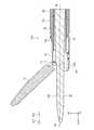
- FIG. 1is a diagram showing a treatment system according to the first embodiment.
- FIG. 2is a diagram illustrating a configuration of a treatment tool.
- FIG. 3is a diagram illustrating the configuration of the treatment tool.
- FIG. 4is a diagram illustrating a connection structure between the inner pipe and the slider receiver.
- FIG. 5is a diagram illustrating a connection structure between the inner pipe and the slider receiver.
- FIG. 6is a diagram illustrating a connection structure between the inner pipe and the slider receiver.
- FIG. 7is a diagram illustrating a connection structure between the inner pipe and the slider receiver.
- FIG. 8is a diagram illustrating a mounting structure of the pressing member according to the second embodiment.
- FIG. 9is a diagram illustrating a mounting structure of the pressing member according to the third embodiment.
- FIG. 10is a diagram illustrating a mounting structure of the pressing member according to the fourth embodiment.
- FIG. 11is a diagram illustrating a mounting structure of the pressing member according to the fifth embodiment.
- FIG. 1is a diagram showing a treatment system 1 according to the first embodiment.
- the treatment system 1treats the target site in the living tissue by applying ultrasonic energy and high frequency energy to the target site (hereinafter referred to as the target site).
- the treatment that can be performed by the treatment system 1 according to the first embodimentis a treatment such as coagulation (sealing) of the target site or incision of the target site. Further, the procedure may be such that coagulation and incision are performed at the same time.
- the treatment system 1includes a treatment tool 2 and a control device 3.
- the X-axisis an axis parallel to the central axis Ax (FIG. 1) of the sheath 10.
- the central axis Axcorresponds to the longitudinal axis according to the present invention.
- the Y-axisis an axis orthogonal to the paper surface of FIG.
- the Z axisis an axis along the vertical direction of FIG.
- FIGS. 2 and 3are diagrams illustrating the configuration of the treatment tool 2. Specifically, FIGS. 2 and 3 are cross-sectional views taken from the + Y-axis side while cutting the treatment tool 2 by the XZ plane including the central axis Ax.
- the treatment tool 2is an ultrasonic treatment tool that treats the target site by applying ultrasonic energy and high frequency energy to the target site.
- the treatment tool 2includes a handpiece 4 and an ultrasonic transducer 5 (FIGS. 1 and 3).
- the handpiece 4includes a holding case 6 (FIGS. 1 and 3), a movable handle 7 (FIGS. 1 and 3), a switch 8 (FIGS. 1 and 3), and a switch 8.
- a rotary knob 9(FIGS. 1 and 3), a sheath 10, a jaw 11 (FIGS. 1 and 2), and a vibration transmitting member 12 are provided.
- the holding case 6supports the entire treatment tool 2. As shown in FIG. 1 or 3, the holding case 6 has a substantially cylindrical holding case main body 61 coaxial with the central axis Ax, and extends from the holding case main body 61 to the ⁇ Z axis side, and is operated by an operator. It is provided with a fixed handle 62 that is gripped by an operator such as.
- the movable handle 7corresponds to the operation input member according to the present invention.
- the movable handle 7accepts a closing operation and an opening operation by an operator such as an operator.
- the movable handle 7includes a handle base 71 (FIG. 3), an operation unit 72 (FIG. 1), and a connection unit 73 (FIG. 1).
- the handle base 71is located inside the holding case 6.
- the portion of the handle base 71 on the + Z axis sideis rotatably supported with respect to the holding case 6 about a first rotation axis Rx1 (FIG. 3) parallel to the Y axis.
- the operation unit 72is a part that receives a closing operation and an opening operation by an operator such as an operator, and is located outside the holding case 6 as shown in FIG.
- the connecting portion 73is arranged so as to straddle the inside and outside of the holding case 6, and is a portion that connects the handle base 71 and the operating portion 72.
- the movable handle 7rotates counterclockwise in FIG. 3 with the first rotation axis Rx1 as the center. That is, the operation unit 72 moves in a direction close to the fixed handle 62.
- the movable handle 7rotates clockwise in FIG. 3 with respect to the first rotation axis Rx1. That is, the operation unit 72 moves in a direction away from the fixed handle 62.
- the switch 8is provided in a state of being exposed to the outside from the side surface of the tip side Ar1 of the fixed handle 62. Then, the switch 8 accepts a treatment operation by an operator such as an operator.
- the treatment operationis an operation of applying ultrasonic energy or high frequency energy to the target site.
- the rotary knob 9has a substantially cylindrical shape coaxial with the central axis Ax, and is provided on the tip side Ar1 of the holding case main body 61 as shown in FIG. Then, the rotation knob 9 accepts a rotation operation by an operator such as an operator. By the rotation operation, the rotation knob 9 rotates about the central axis Ax with respect to the holding case main body 61. Further, the rotation of the rotary knob 9 causes the jaw 11 and the vibration transmission member 12 to rotate about the central axis Ax.
- the sheath 10has a substantially cylindrical shape as a whole. As shown in FIGS. 1 to 3, the sheath 10 includes an outer pipe 13, an inner pipe 14 (FIGS. 2 and 3), a holding portion 15 (FIG. 3), and a slider receiver 16 (FIG. 3). It is provided with a slider 17 (FIG. 3).
- the outer pipe 13is a cylindrical pipe made of a material such as metal. In the outer pipe 13, the outer peripheral surface is covered with an electrically insulating outer tube TO (FIG. 2). Further, the end of Ar1 on the tip side of the outer pipe 13 extends in a direction orthogonal to the paper surface of FIGS. 1 and 2, and the jaw 11 can be rotated around the second rotation axis Rx2 (FIG. 2).
- the first pin 131(FIGS. 1 and 2) that supports the shaft is fixed. Further, at the end of the tip side Ar1 of the outer pipe 13, a notch 132 (FIG. 2) extending from the tip toward the proximal end side Ar2 is formed on the + Z axis side.
- the inner pipe 14corresponds to the tubular member according to the present invention.
- the inner pipe 14is a cylindrical pipe having a diameter smaller than that of the outer pipe 13. Further, the inner pipe 14 is inserted into the outer pipe 13 in a state of being coaxial with the outer pipe 13.
- an arm portion 141 projecting toward the distal end side Ar1is provided on the + Z axis side of the end portion of the distal end side Ar1 as shown in FIG.
- a second pin 111which is provided on the jaw 11 and extends in parallel with the second rotation axis Rx2 (first pin 131), is inserted into the arm portion 141.
- the holding portion 15is made of a material having electrical insulation such as resin, and has a substantially cylindrical shape. As shown in FIG. 3, the holding portion 15 is inserted into the rotating knob 9 and the holding case main body 61 while straddling the rotating knob 9 and the holding case main body 61. Then, the holding portion 15 holds the vibration transmitting member 12 inserted inside. Further, the holding portion 15 is mechanically connected to the rotary knob 9 and the outer pipe 13 at the end portion of the tip side Ar1. That is, the holding portion 15, the outer pipe 13, the jaw 11, and the vibration transmission member 12 rotate about the central axis Ax together with the rotary knob 9 in response to the rotation operation to the rotary knob 9 by an operator such as an operator. do.
- the slider receiver 16corresponds to the drive member according to the present invention.
- the slider receiver 16is made of a material having electrical insulation such as resin, and has a substantially cylindrical shape.
- the slider receiver 16is arranged so as to be movable along the central axis Ax with respect to the holding portion 15 with the holding portion 15 inserted therein.
- the end portion of the tip side Ar1 of the slider receiver 16is allowed to move along the central axis Ax with respect to the holding portion 15, and the inner pipe 14 is restricted from rotating around the central axis Ax. It is connected to the end portion of the base end side Ar2 in.
- the slider receiver 16 and the inner pipe 14rotate about the central axis Ax together with the rotary knob 9 in response to the rotation operation to the rotary knob 9 by an operator such as an operator.
- the connection structure between the inner pipe 14 and the slider receiver 16will be described later.
- the slider 17has a substantially cylindrical shape, and is arranged so as to be movable along the central axis Ax with respect to the slider receiver 16 with the slider receiver 16 inserted therein. Then, as described above, the slider 17 is engaged with the movable handle 7 (the end portion of the handle base 71 on the + Z axis side).
- the slider 17, the slider receiver 16, and the inner pipe 14operate as shown below in response to the operation of the movable handle 7 by an operator such as an operator.
- the slider 17is moved to the tip side Ar1 along the central axis Ax by the movable handle 7 (the end on the + Z axis side of the handle base 71) in response to the closing operation of the movable handle 7 by an operator such as an operator. Be pushed in.
- the slider receiver 16receives a pressing force from the slider 17 toward the tip end side Ar1 by passing through a coil spring 18 (FIG. 3) disposed between the slider receiver 16 and the slider 17.
- the inner pipe 14moves to the tip side Ar1 along the central axis Ax in conjunction with the slider receiver 16.
- the arm portion 141pushes the second pin 111 toward the tip end side Ar1. Then, the jaw 11 rotates counterclockwise in FIG. 2 about the second rotation axis Rx2. At this time, since the second pin 111 also moves while maintaining a constant distance around the second rotation axis Rx2, the arm portion 141 is deformed toward the + Z axis side provided with the notch portion 132. Move to the tip side Ar1. That is, the jaw 11 moves in a direction (closed direction) closer to the end portion 121 (FIG. 2) of the tip end side Ar1 in the vibration transmission member 12.
- the jaw 11rotates clockwise in FIG. 2 about the second rotation axis Rx2 in response to the opening operation of the movable handle 7 by an operator such as an operator. That is, the jaw 11 moves in a direction (opening direction) away from the end portion 121 of the distal end side Ar1 in the vibration transmission member 12.
- the jaw 11opens and closes with respect to the end portion 121 of the tip end side Ar1 of the vibration transmission member 12 in response to the operation of the movable handle 7 by an operator such as an operator, and with the end portion 121. Grasp the target site between.
- the jaw 11 and the end portion 121correspond to the end effector according to the present invention.
- the coil spring 18 described abovetransmits a driving force corresponding to the operation of the movable handle 7 by an operator such as an operator to the slider receiver 16, and corresponds to the elastic member according to the present invention. Then, the coil spring 18 is used to make the gripping force for gripping the target portion constant between the jaw 11 and the end portion 121 (FIG. 2) of the tip end side Ar1 in the vibration transmission member 12.
- the jaw 11is at least partially made of a conductive material.
- the vibration transmitting member 12is made of a conductive material and has a long shape extending linearly along the central axis Ax. Further, as shown in FIG. 2, the vibration transmission member 12 is inserted into the sheath 10 with the end portion 121 of the distal end side Ar1 protruding outward. At this time, the end portion of the base end side Ar2 of the vibration transmission member 12 is mechanically connected to the ultrasonic transducer 5 as shown in FIG. That is, the vibration transmission member 12 transmits the ultrasonic vibration generated by the ultrasonic transducer 5 from the end portion of the proximal end side Ar2 to the end portion 121 of the distal end side Ar1.
- the ultrasonic vibrationis a longitudinal vibration that vibrates in a direction along the central axis Ax.
- the outer peripheral surface of the vibration transmission member 12is covered with an electrically insulating inner tube TI (FIG. 2) in order to ensure electrical insulation between the outer pipe 13 or the inner pipe 14 and the vibration transmission member 12. Has been done.
- the ultrasonic transducer 5includes a TD (transducer) case 51 and an ultrasonic transducer 52 (FIG. 3).
- the TD case 51supports the ultrasonic vibrator 52 and is detachably connected to the holding case main body 61.
- the ultrasonic vibrator 52generates ultrasonic vibration under the control of the control device 3.
- the ultrasonic vibrator 52is composed of a BLT (bolt-tightened Langevin type vibrator). Note that FIG. 3 shows only the front mass 521 connected to the end portion of the proximal end side Ar2 of the vibration transmission member 12 among the ultrasonic vibrators 52 (BLT) for convenience of explanation.
- the control device 3comprehensively controls the operation of the treatment tool 2 by passing through the electric cable C (FIG. 1). Specifically, the control device 3 detects a treatment operation on the switch 8 by an operator such as an operator by passing through the electric cable C. Then, when the control device 3 detects the treatment operation, the target portion gripped between the jaw 11 and the end portion 121 of the distal end side Ar1 of the vibration transmission member 12 via the electric cable C. Ultrasonic energy or high frequency energy is applied to the device. That is, the control device 3 treats the target site.
- the control device 3supplies driving power to the ultrasonic vibrator 52 via the electric cable C.
- the ultrasonic vibrator 52generates longitudinal vibration (ultrasonic vibration) that vibrates in the direction along the central axis Ax.
- the end portion 121 of the tip side Ar1 in the vibration transmission member 12vibrates with a desired amplitude due to the longitudinal vibration.
- ultrasonic vibrationis applied from the end portion 121 to the target portion gripped between the jaw 11 and the end portion 121. In other words, ultrasonic energy is applied to the target portion from the end portion 121.
- the control device 3when applying high frequency energy to the target portion, supplies high frequency power between the jaw 11 and the vibration transmission member 12 via the electric cable C. As a result, a high-frequency current flows through the target portion gripped between the jaw 11 and the end portion 121 of the distal end side Ar1 of the vibration transmission member 12. In other words, high frequency energy is applied to the target portion.
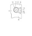
- FIG. 4is an exploded perspective view of the connection portion between the end portion of the base end side Ar2 and the slider receiver 16 in the inner pipe 14.
- FIG. 5is a perspective view showing a state in which the end portion of the base end side Ar2 of the inner pipe 14 and the slider receiver 16 are connected to each other.
- FIG. 6is a cross-sectional view of the connection portion between the end portion of the base end side Ar2 and the slider receiver 16 in the inner pipe 14 cut along a plane orthogonal to the central axis Ax.
- FIG. 7is a diagram showing a first engaging portion 142 provided at the end portion of the base end side Ar2 in the inner pipe 14.
- a first engaging portion 142 that engages with the slider receiver 16is provided at the end of the base end side Ar2 of the inner pipe 14.
- the first engaging portion 142is a substantially rectangular notch (through hole) penetrating the outer peripheral surface and the inner peripheral surface of the inner pipe 14.
- connection base 161 and first and second connection portions 162 and 163are provided at the end portion of the distal end side Ar1 of the slider receiver 16.
- the connection base 161is a portion where the first and second connection portions 162 and 163 are provided.
- the connection substrate 161has a flat plate shape, the plate surface is orthogonal to the central axis Ax, and the connection substrate 161 is bridged between the inner peripheral surfaces of the slider receiver 16 in a posture straddling the central axis Ax. There is. In the connection substrate 161 at the position of the central axis Ax, as shown in FIG.
- a circular insertion hole 1611that penetrates the front and back surfaces and is centered on the central axis Ax is provided.
- the insertion hole 1611is a hole through which the vibration transmission member 12 is inserted.
- the pair of holes 1612 provided between the inner peripheral surface of the slider receiver 16 and the connection base 161each function as holes through which the holding portion 15 is inserted.
- the first connecting portion 162is a portion connecting to the end portion of the proximal end side Ar2 in the inner pipe 14. As shown in FIGS. 4 to 6, the first connecting portion 162 includes a base 1621 and a second engaging portion 1622 (FIGS. 4 and 6).
- the base 1621is a portion of the connection substrate 161 that protrudes from the position on the lower side of the insertion hole 1611 toward the tip side Ar1 on the plate surface of the tip side Ar1.
- the second engaging portion 1622is a protrusion provided on the upper surface of FIGS. 4 and 6 of the base 1621 and projecting toward the upper side. The tip of the second engaging portion 1622 (the upper end surface in FIGS.
- the second engaging portion 1622has an outer shape that is slightly smaller than the inner shape of the first engaging portion 142, and is fitted to the first engaging portion 142. Engage with the first engaging portion 142.
- the second connecting portion 163is a portion to which the pressing member 19 described later is connected. As shown in FIGS. 4 to 6, the second connecting portion 163 includes a convex portion 1631 and a retaining portion 1632 (FIGS. 4 and 5).
- the convex portion 1631is a portion to which the pressing member 19 is attached.
- the convex portion 1631has a cylindrical shape that protrudes from the position on the upper side of the insertion hole 1611 toward the tip side Ar1 on the plate surface of the tip side Ar1 in the connection substrate 161.
- the retaining portion 1632is provided at the protruding end of the convex portion 1631 (the end surface of the tip side Ar1), and prevents the pressing member 19 attached to the convex portion 1631 from falling off from the protruding end of the convex portion 1631. It is a part.
- the second engaging portion 1622is fitted to the first engaging portion 142, that is, the end portion of the base end side Ar2 of the inner pipe 14 is connected to the slider receiver 16. It is a member that maintains the state of being in a state of being.
- the pressing member 19includes a base portion 191 (FIGS. 4 and 6) and a pair of projecting portions 192.
- the base portion 191is a portion extending in the vertical direction in FIGS. 4 and 6.
- the pair of projecting portions 192are portions of the base portion 191 that project from the upper and lower ends in positions substantially parallel to each other in FIGS. 4 and 6. That is, the pressing member 19 has a substantially U-shape as a whole. Further, the U-shaped opening portion in the pressing member 19 corresponds to the opening portion 193 according to the present invention.
- a fitting recess 194 and a pair of inclined surfaces 195are provided inside the U-shape of the pressing member 19.
- the fitting recess 194is a portion to which the convex portion 1631 fits, and is composed of an arcuate concave curved surface that follows the outer peripheral shape of the convex portion 1631.
- the pair of inclined surfaces 195are inclined surfaces that are separated from each other toward the opening 193 from the positions in contact with the fitting recess 194.
- the operatorfits the second engaging portion 1622 to the first engaging portion 142 while applying the base end of the inner pipe 14 to the plate surface of the distal end side Ar1 of the connecting substrate 161.
- the operatorholds the pressing member 19 in his hand and inserts the convex portion 1631 from the opening 193 into the U-shape inside the pressing member 19.
- the pressing member 19has the pair of protrusions with the base 191 as a base point by pressing the pair of protrusions 192 from the convex portions 1631 while the convex portions 1631 slide on the pair of inclined surfaces 195.
- Each tip of the portion 192is elastically deformed in a direction in which they are separated from each other. Then, the pressing member 19 returns to its original shape by fitting the convex portion 1631 into the fitting concave portion 194. As a result, the pressing member 19 is attached to the convex portion 1631. In this state, the pressing member 19 is provided at a position facing the second engaging portion 1622 with the inner pipe 14 interposed therebetween. Then, the pressing member 19 maintains the state in which the second engaging portion 1622 is fitted to the first engaging portion 142 by pressing the outer peripheral surface of the inner pipe 14 toward the central axis Ax. .. That is, the inner pipe 14 is fixed to the slider receiver 16. The operator can remove the inner pipe 14 from the slider receiver 16 by performing an operation opposite to the connection method described above.
- the inner pipeis simply fitted with the second engaging portion 1622 to the first engaging portion 142 and the pressing member 19 attached to the convex portion 1631. 14 and the slider receiver 16 can be fixed. Therefore, when fixing the inner pipe 14 to the slider receiver 16, it is not necessary to perform welding as in the conventional case, and the assembling property can be improved.
- the inner pipe 14, the slider receiver 16, and the likehave a structure that advances and retreats in the direction along the central axis Ax. Therefore, a large force is applied to the inner pipe 14, the slider receiver 16, and the like in the direction along the central axis Ax.
- the above-mentioned structureis adopted as the attachment structure of the pressing member 19 to the convex portion 1631, the above-mentioned large force is not applied to the pressing member 19. That is, it is possible to realize a structure capable of transmitting the driving force required for opening and closing the jaw 11 while improving the assembling property.
- Remanufacturing the treatment toolmeans disassembling, cleaning, replacing parts, reassembling, sterilizing, etc. the used treatment tool after treating the target site, and confirming that it has the required performance. This means that the treatment tool can be used again. Then, in the treatment tool 2 according to the first embodiment, the pressing member 19 is detachably attached to the slider receiver 16. Therefore, the remanufacturing of the treatment tool 2 is facilitated.
- the pressing member 19is provided at a position facing the second engaging portion 1622 with the inner pipe 14 interposed therebetween. Therefore, it is possible to maintain a good state in which the second engaging portion 1622 is fitted to the first engaging portion 142 by using only one pressing member 19. Therefore, the number of parts can be reduced.
- the second embodimentis different from the first embodiment in that the shapes of the pressing member 19 and the convex portion 1631 are changed.
- the pressing member 19 according to the second embodimentwill be referred to as a pressing member 19A.
- the convex portion 1631 according to the second embodimentis referred to as a convex portion 1631A.
- FIG. 8is a diagram illustrating a mounting structure of the pressing member 19A according to the second embodiment. Specifically, FIG. 8 is a cross-sectional view corresponding to FIG.
- the pressing member 19A according to the second embodimentis different from the pressing member 19 according to the first embodiment described above in that a pair of attachment / maintenance portions 196 are provided as shown in FIG.
- the pair of mounting maintenance portions 196is a portion that restricts the movement of the pressing member 19A in the direction opposite to the mounting direction Ar3 (FIG. 8) in which the pressing member 19A is attached to the convex portion 1631A.
- the pair of mounting maintenance portions 196are respectively located at the boundary between the fitting recess 194 and the pair of inclined surfaces 195, and extend in directions close to each other, and are formed by flat portions intersecting with Ar4 in the opposite direction. Each is configured.
- the convex portion 1631Ahas a D-shaped cross section corresponding to the pair of mounting maintenance portions 196 described above and whose surface on the mounting direction Ar3 side is a flat surface. That is, after the convex portion 1631A is fitted to the fitting concave portion 194, the pair of mounting maintenance portions 196 has a structure that restricts the movement of the pressing member 19A in the reverse direction Ar4.
- the same effect as that of the first embodiment described aboveis obtained.
- the pair of mounting maintenance portions 196regulates the movement of the pressing member 19A in the reverse direction Ar4. .. Therefore, the structure can be such that it is difficult for a person who is not related to the manufacturer who remanufactures the treatment tool to remanufacture the treatment tool.
- the third embodimentwill be described.
- the same components as those in the first embodimentwill be designated by the same reference numerals, and detailed description thereof will be omitted or simplified.
- the third embodimentis different from the first embodiment described above in that the shape of the pressing member 19 is changed.
- the pressing member 19 according to the third embodimentwill be referred to as a pressing member 19B.
- FIG. 9is a diagram illustrating a mounting structure of the pressing member 19B according to the third embodiment. Specifically, FIG. 9 is a cross-sectional view corresponding to FIG. As shown in FIG. 9, the pressing member 19B according to the third embodiment is different from the pressing member 19 according to the first embodiment in that the thin-walled portion 197 is provided.
- the thin-walled portion 197is provided at the base portion 191 facing the opening 193, and is a portion of the base portion 191 that is thinner than other portions. That is, when the convex portion 1631 is fitted to the fitting concave portion 194 and then the pressing member 19B is forcibly removed from the convex portion 1631, the pressing member 19B is damaged with the thin-walled portion 197 as a base point. It has a structure to do.
- the same effect as that of the first embodiment described aboveis obtained.
- the convex portion 1631is fitted to the fitting concave portion 194 and then the pressing member 19B is forcibly removed from the convex portion 1631, the thin-walled portion 197 is used as a base point.
- the structureis such that the pressing member 19B is damaged. Therefore, the structure can be such that it is difficult for a person who is not related to the manufacturer who remanufactures the treatment tool to remanufacture the treatment tool.
- FIG. 10is a diagram illustrating a mounting structure of the pressing member 19 according to the fourth embodiment.
- FIG. 10is a cross-sectional view corresponding to FIG.
- the fixing member 20Cis a member that fixes the pressing member 19 to the convex portion 1631.
- the fixing member 20Cis an adhesive. Then, the fixing member 20C is applied between the convex portion 1631 and the pressing member 19. That is, the structure is such that the pressing member 19 cannot be removed from the convex portion 1631 by curing the fixing member 20C.
- the same effect as that of the first embodiment described aboveis obtained.
- the pressing member 19cannot be removed from the convex portion 1631 by the fixing member 20C. Therefore, the structure can be such that a person unrelated to the manufacturer who remanufactures the treatment tool cannot remanufacture the treatment tool.
- FIG. 11is a diagram illustrating a mounting structure of the pressing member 19 according to the fifth embodiment. Specifically, FIG. 11 is a cross-sectional view corresponding to FIG.
- the fixing member 20Dis a member that fixes the pressing member 19 to the convex portion 1631 in the same manner as the fixing member 20C described in the third embodiment described above.
- the fixing member 20Dis a pin. Then, after the pressing member 19 is attached to the convex portion 1631, the fixing member 20D is fixed to the pressing member 19 in a posture of being bridged between the pair of inclined surfaces 195. That is, the structure is such that the pressing member 19 cannot be removed from the convex portion 1631 because the convex portion 1631 is caught by the fixing member 20D.
- the same effect as that of the first embodiment described aboveis obtained.
- the pressing member 19cannot be removed from the convex portion 1631 by the fixing member 20D. Therefore, the structure can be such that a person unrelated to the manufacturer who remanufactures the treatment tool cannot remanufacture the treatment tool.
- the treatment tool according to the present inventionis configured to apply both ultrasonic energy and high frequency energy to the target portion, but the present invention is not limited to this, and ultrasonic energy and high frequency energy are not limited to this. , And at least one of the thermal energies may be applied.
- "giving heat energy to the target portion”means transferring the heat generated in the heater or the like to the target portion.
- the inner pipe 14is used as the tubular member according to the present invention, but the present invention is not limited to this.
- the outer pipe 13may be adopted as the tubular member according to the present invention. That is, the jaw 11 may be opened and closed by moving the outer pipe 13 along the central axis Ax.
- the elastically deformable pressing member 19is adopted as the pressing member according to the present invention, but the present invention is not limited to this, and other fasteners such as screws can be used as the pressing member according to the present invention. You may adopt it.
- only one pressing member 19is adopted, but the number of pressing members according to the present invention is not limited to one, and may be plural.
- the plurality of pressing membersare provided at positions where the inner pipe 14 is pressed toward the central axis Ax.
- the pressing member 19has a linear path from the opening 193 to the fitting recess 194 along the mounting direction Ar3, but the path is not limited to this and is curved. It may be the route of, or it may be an L-shaped route.
Landscapes
- Health & Medical Sciences (AREA)
- Surgery (AREA)
- Life Sciences & Earth Sciences (AREA)
- Engineering & Computer Science (AREA)
- Biomedical Technology (AREA)
- Public Health (AREA)
- Nuclear Medicine, Radiotherapy & Molecular Imaging (AREA)
- Veterinary Medicine (AREA)
- General Health & Medical Sciences (AREA)
- Heart & Thoracic Surgery (AREA)
- Medical Informatics (AREA)
- Molecular Biology (AREA)
- Animal Behavior & Ethology (AREA)
- Physics & Mathematics (AREA)
- Otolaryngology (AREA)
- Plasma & Fusion (AREA)
- Dentistry (AREA)
- Mechanical Engineering (AREA)
- Surgical Instruments (AREA)
Abstract
Description
Translated fromJapanese本発明は、処置具に関する。The present invention relates to a treatment tool.
従来、生体組織における処置の対象となる部位(以下、対象部位と記載)に対してエネルギを付与することによって当該対象部位を処置する処置具が知られている(例えば、特許文献1参照)。
特許文献1に記載の処置具は、開閉可能とするジョーと、先端側の端部が当該ジョーに対して接続された長尺状の内側パイプと、内側パイプにおける基端側の端部が接続された可動筒状部材と、操作者による操作を受け付ける可動ハンドルとを備える。そして、可動ハンドルへの操作に応じて可動筒状部材及び内側パイプが長手軸に沿う方向に移動することによって、ジョーは、開閉する。Conventionally, a treatment tool for treating a target site (hereinafter referred to as a target site) in a living tissue by applying energy to the target site has been known (see, for example, Patent Document 1).
The treatment tool described in Patent Document 1 has a jaw that can be opened and closed, a long inner pipe whose tip end is connected to the jaw, and a proximal end of the inner pipe. It is provided with a movable tubular member and a movable handle that accepts an operation by an operator. Then, the jaw opens and closes as the movable tubular member and the inner pipe move in the direction along the longitudinal axis in response to the operation on the movable handle.
ここで、特許文献1に記載の処置具では、内側パイプは、可動筒状部材に対して、以下に示すように、接続される。
先ず、作業者は、内側パイプにおける基端側の端部に対して接続部材を溶接によって固定する。この後、作業者は、当該基端側の端部を可動筒状部材の内部に挿通するとともに、当該可動筒状部材の外周面から接続ピンを当該可動筒状部材の内部に向けて挿通し、当該接続ピンを接続部材に対して固定する。これによって、内側パイプは、可動筒状部材に対して接続される。Here, in the treatment tool described in Patent Document 1, the inner pipe is connected to the movable tubular member as shown below.
First, the operator fixes the connecting member to the end portion of the inner pipe on the base end side by welding. After that, the operator inserts the end portion on the base end side into the inside of the movable tubular member, and inserts the connection pin from the outer peripheral surface of the movable tubular member toward the inside of the movable tubular member. , Fix the connection pin to the connection member. Thereby, the inner pipe is connected to the movable tubular member.
しかしながら、特許文献1に記載の処置具では、内側パイプを可動筒状部材に対して接続するために、当該内側パイプに対して接続部材を溶接によって固定する必要がある。すなわち、当該溶接を行うため、組み立て性を向上させることが難しい。However, in the treatment tool described in Patent Document 1, in order to connect the inner pipe to the movable tubular member, it is necessary to fix the connecting member to the inner pipe by welding. That is, it is difficult to improve the assembleability because the welding is performed.
本発明は、上記に鑑みてなされたものであって、組み立て性を向上させることができる処置具を提供することを目的とする。The present invention has been made in view of the above, and an object of the present invention is to provide a treatment tool capable of improving assembleability.
上述した課題を解決し、目的を達成するために、本発明に係る処置具は、生体組織を処置するエンドエフェクタと、操作者による操作を受け付ける操作入力部材と、長手軸に沿って設けられ、一端が前記エンドエフェクタに対して接続され、他端に第1の係合部が設けられた筒状部材と、前記操作入力部材への前記操作に応じて前記長手軸に沿った方向に移動するとともに、前記第1の係合部と係合する第2の係合部を有する駆動部材と、前記第1の係合部と前記第2の係合部とが係合した状態で、前記筒状部材の中心軸に向けて前記筒状部材に対して当接することによって前記筒状部材と前記駆動部材とを連結する押圧部材と、を備える。In order to solve the above-mentioned problems and achieve the object, the treatment tool according to the present invention is provided with an end effector for treating a living tissue, an operation input member for receiving an operation by an operator, and an operation input member along a longitudinal axis. One end is connected to the end effector, and the tubular member provided with the first engaging portion at the other end moves in a direction along the longitudinal axis in response to the operation on the operation input member. At the same time, the cylinder is in a state where the drive member having the second engaging portion that engages with the first engaging portion, and the first engaging portion and the second engaging portion are engaged with each other. A pressing member for connecting the tubular member and the driving member by abutting against the tubular member toward the central axis of the shaped member is provided.
本発明に係る処置具は、生体組織を処置するエンドエフェクタと、操作者による操作を受け付ける操作入力部材と、長手軸に沿って設けられ、一端が前記エンドエフェクタに対して接続され、他端に第1の係合部が設けられた筒状部材と、前記操作入力部材への前記操作に応じて前記長手軸に沿った方向に移動するとともに、前記第1の係合部と係合する第2の係合部を有する駆動部材と、前記第1の係合部と前記第2の係合部とが係合した状態で、前記筒状部材の中心軸に向けて前記筒状部材に対して当接することによって前記筒状部材と前記駆動部材とを連結する押圧部材と、を備え、前記押圧部材には、前記押圧部材を前記駆動部材に対して取り付ける取付方向とは逆方向への前記押圧部材の移動を規制する取付維持部と、他の部位よりも薄い薄肉部との少なくとも一方が設けられている。The treatment tool according to the present invention is provided along a longitudinal axis with an end effector for treating a living tissue, an operation input member for receiving an operation by an operator, one end connected to the end effector, and the other end. A tubular member provided with a first engaging portion and a first engaging portion that moves in a direction along the longitudinal axis in response to the operation on the operation input member and engages with the first engaging portion. With the drive member having the
本発明に係る処置具は、生体組織を処置するエンドエフェクタと、操作者による操作を受け付ける操作入力部材と、長手軸に沿って設けられ、一端が前記エンドエフェクタに対して接続され、他端に第1の係合部が設けられた筒状部材と、前記操作入力部材への前記操作に応じて前記長手軸に沿った方向に移動するとともに、前記第1の係合部と係合する第2の係合部を有する駆動部材と、前記第1の係合部と前記第2の係合部とが係合した状態で、前記筒状部材の中心軸に向けて前記筒状部材に対して当接することによって前記筒状部材と前記駆動部材とを連結する押圧部材と、前記押圧部材を前記駆動部材に対して固定する固定部材と、を備える。The treatment tool according to the present invention is provided along a longitudinal axis with an end effector for treating a living tissue, an operation input member for receiving an operation by an operator, one end connected to the end effector, and the other end. A tubular member provided with a first engaging portion and a first engaging portion that moves in a direction along the longitudinal axis in response to the operation on the operation input member and engages with the first engaging portion. With the drive member having the
本発明に係る処置具によれば、組み立て性を向上させることができる。According to the treatment tool according to the present invention, the assembling property can be improved.
以下に、図面を参照しつつ、本発明を実施するための形態(以下、実施の形態)について説明する。なお、以下に説明する実施の形態によって本発明が限定されるものではない。さらに、図面の記載において、同一の部分には同一の符号を付している。Hereinafter, embodiments for carrying out the present invention (hereinafter referred to as embodiments) will be described with reference to the drawings. The present invention is not limited to the embodiments described below. Further, in the description of the drawings, the same parts are designated by the same reference numerals.
〔処置システムの概略構成〕
図1は、実施の形態1に係る処置システム1を示す図である。
処置システム1は、生体組織における処置の対象となる部位(以下、対象部位と記載)に対して超音波エネルギと高周波エネルギとを付与することによって、当該対象部位を処置する。なお、本実施の形態1に係る処置システム1によって実行可能とする処置は、対象部位の凝固(封止)、あるいは対象部位の切開等といった処置である。また、凝固と切開とを同時に行うような処置であってもよい。この処置システム1は、図1に示すように、処置具2と、制御装置3とを備える。[Outline configuration of treatment system]
FIG. 1 is a diagram showing a treatment system 1 according to the first embodiment.
The treatment system 1 treats the target site in the living tissue by applying ultrasonic energy and high frequency energy to the target site (hereinafter referred to as the target site). The treatment that can be performed by the treatment system 1 according to the first embodiment is a treatment such as coagulation (sealing) of the target site or incision of the target site. Further, the procedure may be such that coagulation and incision are performed at the same time. As shown in FIG. 1, the treatment system 1 includes a
〔処置具の構成〕
なお、以下では、処置具2の構成を説明するにあたって、互いに直交するX軸、Y軸、及びZ軸のXYZ座標軸を用いる。X軸は、シース10の中心軸Ax(図1)に平行な軸である。当該中心軸Axは、本発明に係る長手軸に相当する。Y軸は、図1の紙面に直交する軸である。Z軸は、図1の上下方向に沿う軸である。また、以下では、中心軸Axに沿う一方側(+X軸側)を先端側Ar1と記載し、他方側(-X軸側)を基端側Ar2と記載する。
図2及び図3は、処置具2の構成を説明する図である。具体的に、図2及び図3は、中心軸Axを含むXZ平面によって処置具2を切断するとともに+Y軸側から見た断面図である。[Structure of treatment tool]
In the following, in explaining the configuration of the
2 and 3 are diagrams illustrating the configuration of the
処置具2は、対象部位に対して超音波エネルギと高周波エネルギとを付与することによって、当該対象部位を処置する超音波処置具である。この処置具2は、図1~図3に示すように、ハンドピース4と、超音波トランスデューサ5(図1,図3)とを備える。
ハンドピース4は、図1~図3に示すように、保持ケース6(図1,図3)と、可動ハンドル7(図1,図3)と、スイッチ8(図1,図3)と、回転ノブ9(図1,図3)と、シース10と、ジョー11(図1,図2)と、振動伝達部材12とを備える。The
As shown in FIGS. 1 to 3, the
保持ケース6は、処置具2全体を支持する。この保持ケース6は、図1または図3に示すように、中心軸Axと同軸となる略円筒状の保持ケース本体61と、当該保持ケース本体61から-Z軸側に延在し、術者等の操作者によって把持される固定ハンドル62とを備える。The
可動ハンドル7は、本発明に係る操作入力部材に相当する。この可動ハンドル7は、術者等の操作者による閉操作及び開操作をそれぞれ受け付ける。この可動ハンドル7は、図1または図3に示すように、ハンドル基部71(図3)と、操作部72(図1)と、接続部73(図1)とを備える。
ハンドル基部71は、保持ケース6の内部に位置する。そして、ハンドル基部71における+Z軸側の部分は、保持ケース6に対して、Y軸に平行となる第1の回転軸Rx1(図3)を中心として回転可能に軸支されている。また、ハンドル基部71における+Z軸側の端部は、二股に分岐した状態で+Z軸側に向けて突出し、シース10を構成するスライダ17と係合する。
操作部72は、術者等の操作者による閉操作及び開操作をそれぞれ受け付ける部分であり、図1に示すように、保持ケース6の外部に位置する。
接続部73は、保持ケース6の内外を跨いで配設され、ハンドル基部71と操作部72とを接続する部分である。The
The
The
The connecting
そして、可動ハンドル7は、術者等の操作者による閉操作を受け付けた場合には、第1の回転軸Rx1を中心として図3中、反時計回りに回転する。すなわち、操作部72は、固定ハンドル62に近接する方向に移動する。一方、可動ハンドル7に対する開操作を受け付けた場合には、当該可動ハンドル7は、第1の回転軸Rx1を中心として図3中、時計回りに回転する。すなわち、操作部72は、固定ハンドル62から離間する方向に移動する。Then, when the
スイッチ8は、図1または図3に示すように、固定ハンドル62における先端側Ar1の側面から外部に露出した状態で設けられている。そして、スイッチ8は、術者等の操作者による処置操作を受け付ける。当該処置操作は、対象部位に対して超音波エネルギや高周波エネルギを付与させる操作である。As shown in FIG. 1 or 3, the
回転ノブ9は、中心軸Axと同軸となる略円筒形状を有し、図3に示すように、保持ケース本体61の先端側Ar1に設けられている。そして、回転ノブ9は、術者等の操作者による回転操作を受け付ける。当該回転操作により、回転ノブ9は、保持ケース本体61に対して、中心軸Axを中心として回転する。また、回転ノブ9の回転により、ジョー11及び振動伝達部材12が中心軸Axを中心として回転する。The
シース10は、全体略円筒形状を有する。このシース10は、図1~図3に示すように、アウターパイプ13と、インナーパイプ14(図2,図3)と、保持部15(図3)と、スライダ受け16(図3)と、スライダ17(図3)とを備える。
アウターパイプ13は、金属等の材料によって構成された円筒状のパイプである。
このアウターパイプ13において、外周面は、電気絶縁性のアウターチューブTO(図2)によって被覆されている。
また、アウターパイプ13における先端側Ar1の端部には、図1及び図2の紙面に直交する方向に延在し、ジョー11を第2の回転軸Rx2(図2)を中心として回転可能に軸支する第1のピン131(図1,図2)が固定されている。
さらに、アウターパイプ13における先端側Ar1の端部において、+Z軸側には、先端から基端側Ar2に向けて延在する切欠き部132(図2)が形成されている。The
The
In the
Further, the end of Ar1 on the tip side of the
Further, at the end of the tip side Ar1 of the
インナーパイプ14は、本発明に係る筒状部材に相当する。このインナーパイプ14は、アウターパイプ13よりも径寸法の小さい円筒状のパイプである。また、インナーパイプ14は、アウターパイプ13と同軸となる状態で、当該アウターパイプ13内に挿通されている。
このインナーパイプ14において、先端側Ar1の端部の+Z軸側には、図2に示すように、先端側Ar1に向けて突出する腕部141が設けられている。この腕部141には、ジョー11に設けられ、第2の回転軸Rx2(第1のピン131)に平行となる状態で延在した第2のピン111が挿通されている。The
In the
保持部15は、樹脂等の電気絶縁性を有する材料によって構成され、略円筒形状を有する。この保持部15は、図3に示すように、回転ノブ9及び保持ケース本体61を跨ぐ状態で当該回転ノブ9及び保持ケース本体61内に挿通されている。そして、保持部15は、内部に挿通された振動伝達部材12を保持する。また、保持部15は、先端側Ar1の端部において、回転ノブ9及びアウターパイプ13と機械的に接続する。すなわち、保持部15、アウターパイプ13、ジョー11、及び振動伝達部材12は、術者等の操作者による回転ノブ9への回転操作に応じて、回転ノブ9とともに、中心軸Axを中心として回転する。The holding
スライダ受け16は、本発明に係る駆動部材に相当する。このスライダ受け16は、樹脂等の電気絶縁性を有する材料によって構成され、略円筒形状を有する。そして、スライダ受け16は、内部に保持部15が挿通された状態で、当該保持部15に対して中心軸Axに沿って移動可能に配設されている。ここで、スライダ受け16における先端側Ar1の端部は、保持部15に対して中心軸Axに沿う移動を許容されつつ、中心軸Axを中心とした回転が規制された状態で、インナーパイプ14における基端側Ar2の端部に対して接続されている。すなわち、スライダ受け16及びインナーパイプ14は、術者等の操作者による回転ノブ9への回転操作に応じて、回転ノブ9とともに、中心軸Axを中心として回転する。
なお、インナーパイプ14とスライダ受け16との接続構造については、後述する。The
The connection structure between the
スライダ17は、略円筒形状を有し、内部にスライダ受け16が挿通された状態で、当該スライダ受け16に対して中心軸Axに沿って移動可能に配設されている。そして、スライダ17は、上述したように、可動ハンドル7(ハンドル基部71における+Z軸側の端部)と係合している。The
そして、スライダ17、スライダ受け16、及びインナーパイプ14は、術者等の操作者による可動ハンドル7への操作に応じて、以下に示すように動作する。
スライダ17は、術者等の操作者による可動ハンドル7への閉操作に応じて、当該可動ハンドル7(ハンドル基部71における+Z軸側の端部)によって、中心軸Axに沿って先端側Ar1に押し込まれる。また、スライダ受け16は、スライダ17との間に配設されたコイルバネ18(図3)を経由することによって、スライダ17から先端側Ar1に向けて押圧力を受ける。さらに、インナーパイプ14は、スライダ受け16に連動して、中心軸Axに沿って先端側Ar1に移動する。また、腕部141は、第2のピン111を先端側Ar1に向けて押し込む。そして、ジョー11は、第2の回転軸Rx2を中心として図2中、反時計回りに回転する。このとき、第2のピン111も第2の回転軸Rx2を中心に一定の距離を保った状態で移動するため、腕部141は、切欠き部132が設けられた+Z軸側に変形しながら先端側Ar1に移動する。すなわち、ジョー11は、振動伝達部材12における先端側Ar1の端部121(図2)に対して近接する方向(閉じる方向)に移動する。Then, the
The
また、術者等の操作者による可動ハンドル7への開操作に応じて、ジョー11は、第2の回転軸Rx2を中心として図2中、時計回りに回転する。すなわち、ジョー11は、振動伝達部材12における先端側Ar1の端部121に対して離間する方向(開く方向)に移動する。Further, the
以上のように、ジョー11は、術者等の操作者による可動ハンドル7への操作に応じて、振動伝達部材12における先端側Ar1の端部121に対して開閉し、当該端部121との間で対象部位を把持する。そして、ジョー11と、当該端部121とは、本発明に係るエンドエフェクタに相当する。
ここで、上述したコイルバネ18は、術者等の操作者による可動ハンドル7への操作に応じた駆動力をスライダ受け16に対して伝達しており、本発明に係る弾性部材に相当する。そして、コイルバネ18は、ジョー11と振動伝達部材12における先端側Ar1の端部121(図2)との間で対象部位を把持する把持力を一定にするために用いられる。As described above, the
Here, the
ジョー11は、少なくとも一部が導電性材料によって構成されている。
振動伝達部材12は、導電性材料によって構成され、中心軸Axに沿って直線状に延在する長尺形状を有する。また、振動伝達部材12は、図2に示すように、先端側Ar1の端部121が外部に突出した状態でシース10の内部に挿通される。この際、振動伝達部材12の基端側Ar2の端部は、図3に示すように、超音波トランスデューサ5に機械的に接続する。すなわち、振動伝達部材12は、超音波トランスデューサ5が発生させた超音波振動を基端側Ar2の端部から先端側Ar1の端部121まで伝達する。本実施の形態1では、当該超音波振動は、中心軸Axに沿う方向に振動する縦振動である。
なお、振動伝達部材12の外周面は、アウターパイプ13やインナーパイプ14と当該振動伝達部材12との電気的な絶縁性を確保するために、電気絶縁性のインナーチューブTI(図2)によって被覆されている。The
The
The outer peripheral surface of the
超音波トランスデューサ5は、図1または図3に示すように、TD(トランスデューサ)ケース51と、超音波振動子52(図3)とを備える。
TDケース51は、超音波振動子52を支持するとともに、保持ケース本体61に対して着脱自在に接続する。
超音波振動子52は、制御装置3による制御の下、超音波振動を発生させる。本実施の形態1では、超音波振動子52は、BLT(ボルト締めランジュバン型振動子)によって構成されている。なお、図3では、説明の便宜上、超音波振動子52(BLT)のうち、振動伝達部材12における基端側Ar2の端部に対して接続するフロントマス521のみを図示している。As shown in FIG. 1 or 3, the
The
The
〔制御装置の構成〕
制御装置3は、電気ケーブルC(図1)を経由することによって、処置具2の動作を統括的に制御する。
具体的に、制御装置3は、電気ケーブルCを経由することによって、術者等の操作者によるスイッチ8への処置操作を検知する。そして、制御装置3は、当該処置操作を検知した場合には、電気ケーブルCを経由することによって、ジョー11と振動伝達部材12における先端側Ar1の端部121との間に把持された対象部位に対して超音波エネルギや高周波エネルギを付与する。すなわち、制御装置3は、当該対象部位を処置する。[Control device configuration]
The
Specifically, the
例えば、対象部位に対して超音波エネルギを付与する際には、制御装置3は、電気ケーブルCを経由することによって、超音波振動子52に対して駆動電力を供給する。これによって、超音波振動子52は、中心軸Axに沿う方向に振動する縦振動(超音波振動)を発生させる。また、振動伝達部材12における先端側Ar1の端部121は、当該縦振動によって、所望の振幅で振動する。そして、ジョー11と当該端部121との間に把持された対象部位には、当該端部121から超音波振動が付与される。言い換えれば、当該端部121から対象部位に対して超音波エネルギが付与される。For example, when applying ultrasonic energy to a target portion, the
また、例えば、対象部位に対して高周波エネルギを付与する際には、制御装置3は、電気ケーブルCを経由することによって、ジョー11と振動伝達部材12との間に高周波電力を供給する。これによって、ジョー11と振動伝達部材12における先端側Ar1の端部121との間に把持された対象部位には、高周波電流が流れる。言い換えれば、当該対象部位には、高周波エネルギが付与される。Further, for example, when applying high frequency energy to the target portion, the
〔インナーパイプとスライダ受けとの接続構造〕
次に、インナーパイプ14とスライダ受け16との接続構造について説明する。
図4~図7は、インナーパイプ14とスライダ受け16との接続構造を説明する図である。具体的に、図4は、インナーパイプ14における基端側Ar2の端部とスライダ受け16との接続部位を分解した分解斜視図である。図5は、インナーパイプ14における基端側Ar2の端部とスライダ受け16とが接続された状態を示した斜視図である。図6は、インナーパイプ14における基端側Ar2の端部とスライダ受け16との接続部位を中心軸Axに直交する平面にて切断した断面図である。図7は、インナーパイプ14における基端側Ar2の端部に設けられた第1の係合部142を示す図である。[Connection structure between inner pipe and slider holder]
Next, the connection structure between the
4 to 7 are views for explaining the connection structure between the
インナーパイプ14における基端側Ar2の端部には、図7に示すように、スライダ受け16と係合する第1の係合部142が設けられている。本実施の形態1では、第1の係合部142は、インナーパイプ14の外周面と内周面とを貫通した略矩形状の切り欠き(貫通孔)である。As shown in FIG. 7, a first
スライダ受け16における先端側Ar1の端部には、図4~図6に示すように、接続基体161と、第1,第2の接続部162,163とが設けられている。
接続基体161は、第1,第2の接続部162,163が設けられる部分である。この接続基体161は、図4に示すように、平板形状を有し、板面が中心軸Axに直交し、当該中心軸Axを跨ぐ姿勢でスライダ受け16の内周面間に架け渡されている。
この接続基体161において、中心軸Axの位置には、図4に示すように、表裏を貫通し、当該中心軸Axを中心とする円形状の挿通孔1611が設けられている。この挿通孔1611は、振動伝達部材12が挿通される孔である。
また、スライダ受け16の内周面と接続基体161との間に設けられた一対の孔1612は、保持部15が挿通される孔としてそれぞれ機能する。As shown in FIGS. 4 to 6, a
The
In the
Further, the pair of
第1の接続部162は、インナーパイプ14における基端側Ar2の端部に対して接続する部分である。この第1の接続部162は、図4~図6に示すように、基台1621と、第2の係合部1622(図4,図6)とを備える。
基台1621は、接続基体161における先端側Ar1の板面上において、挿通孔1611よりも図4中、下方側の位置から先端側Ar1に向けて突出した部分である。
第2の係合部1622は、基台1621における図4及び図6中、上方側の面に設けられ、当該上方側に向けて突出する突起である。この第2の係合部1622における突端(図4及び図6中、上方側の端面)は、挿通孔1611に挿通される振動伝達部材12を避けるために、中心軸Axを中心とする円弧状の凹曲面によって構成されている。そして、第2の係合部1622は、第1の係合部142の内形形状よりも若干小さい、外形形状を有し、当該第1の係合部142に対して嵌合することによって、当該第1の係合部142と係合する。The first connecting
The
The second
第2の接続部163は、後述する押圧部材19が接続される部分である。この第2の接続部163は、図4~図6に示すように、凸部1631と、抜け止め部1632(図4,図5)とを備える。
凸部1631は、押圧部材19が取り付けられる部分である。この凸部1631は、接続基体161における先端側Ar1の板面上において、挿通孔1611よりも図4中、上方側の位置から先端側Ar1に向けて突出した円柱形状を有する。
抜け止め部1632は、凸部1631における突端(先端側Ar1の端面)に設けられ、当該凸部1631に対して取り付けられた押圧部材19が当該凸部1631の突端から抜け落ちてしまうことを防止する部分である。The second connecting
The
The retaining
押圧部材19は、第1の係合部142に対して第2の係合部1622が嵌合した状態、言い換えれば、インナーパイプ14における基端側Ar2の端部がスライダ受け16に対して接続した状態を維持する部材である。この押圧部材19は、図4~図6に示すように、基部191(図4,図6)と、一対の突出部192とを備える。
基部191は、図4及び図6中、上下方向に延在した部分である。
一対の突出部192は、基部191における図4及び図6中、上下の端部から互いに略平行となる姿勢でそれぞれ突出した部分である。すなわち、押圧部材19は、全体略U字形状を有する。また、押圧部材19におけるU字状の開口部分は、本発明に係る開口部193に相当する。In the pressing
The
The pair of projecting
そして、押圧部材19におけるU字状の内側には、図4または図6に示すように、嵌合凹部194と、一対の傾斜面195とが設けられている。
嵌合凹部194は、凸部1631が嵌合する部分であり、当該凸部1631の外周形状に倣う円弧状の凹曲面で構成されている。
一対の傾斜面195は、嵌合凹部194に対してそれぞれ接する位置から開口部193に向かうにしたがって互いに離間する傾斜面である。As shown in FIG. 4 or 6, a
The
The pair of
次に、インナーパイプ14とスライダ受け16との接続方法について説明する。
先ず、作業者は、インナーパイプ14の基端を接続基体161における先端側Ar1の板面にあてがいつつ、第1の係合部142に対して第2の係合部1622を嵌合させる。
次に、作業者は、押圧部材19を手に持ち、開口部193から当該押圧部材19におけるU字状の内側に凸部1631を入り込ませる。この際、押圧部材19は、凸部1631が一対の傾斜面195上を摺動しつつ、当該凸部1631から一対の突出部192が押圧されることによって、基部191を基点として当該一対の突出部192における各突端が離間する方向に弾性変形する。そして、押圧部材19は、嵌合凹部194に凸部1631が嵌合することによって、元の形状に戻る。これによって、押圧部材19は、凸部1631に対して取り付けられる。この状態では、押圧部材19は、インナーパイプ14を挟んで第2の係合部1622と対向する位置に設けられる。そして、押圧部材19は、中心軸Axに向けてインナーパイプ14の外周面を押圧することによって、第1の係合部142に対して第2の係合部1622が嵌合した状態を維持する。すなわち、インナーパイプ14は、スライダ受け16に対して固定される。
なお、作業者は、上述した接続方法とは逆の操作を行うことによって、スライダ受け16からインナーパイプ14を取り外すことができる。Next, a method of connecting the
First, the operator fits the second engaging
Next, the operator holds the pressing
The operator can remove the
以上説明した本実施の形態1によれば、以下の効果を奏する。
本実施の形態1に係る処置具2では、第1の係合部142に対して第2の係合部1622を嵌合させ、凸部1631に対して押圧部材19を取り付けるだけで、インナーパイプ14とスライダ受け16とを固定することができる。
したがって、スライダ受け16に対してインナーパイプ14を固定するにあたって、従来のように溶接を行う必要がなく、組み立て性を向上させることができる。According to the first embodiment described above, the following effects are obtained.
In the
Therefore, when fixing the
ところで、インナーパイプ14及びスライダ受け16等は、中心軸Axに沿う方向に進退する構造になっている。このため、インナーパイプ14及びスライダ受け16等には、中心軸Axに沿う方向に大きな力が掛かる。
本実施の形態1に係る処置具2では、凸部1631に対する押圧部材19の取付構造として、上述した構造を採用しているため、当該押圧部材19には、上述した大きな力が掛からない。すなわち、組み立て性を向上させつつ、ジョー11の開閉に必要な駆動力を伝達可能な構造を実現することができる。By the way, the
In the
ところで、近年では、資源の有効活用や医療廃棄物の削減、さらには医療費の低減の可能性等から処置具の再製造が注目されている。
なお、処置具の再製造とは、対象部位を処置した後の使用済みの処置具を分解、洗浄、部品交換、再組立て、滅菌等の処理を行い、必要な性能等を有することを確認することによって、再び当該処置具を使用することができる状態にすることを意味する。
そして、本実施の形態1に係る処置具2では、押圧部材19は、スライダ受け16に対して着脱自在に取り付けられる。このため、処置具2の再製造を容易とする。By the way, in recent years, attention has been paid to the remanufacturing of treatment tools because of the possibility of effective utilization of resources, reduction of medical waste, and reduction of medical expenses.
Remanufacturing the treatment tool means disassembling, cleaning, replacing parts, reassembling, sterilizing, etc. the used treatment tool after treating the target site, and confirming that it has the required performance. This means that the treatment tool can be used again.
Then, in the
本実施の形態1に係る処置具2では、押圧部材19は、インナーパイプ14を挟んで第2の係合部1622と対向する位置に設けられる。このため、1つのみの押圧部材19によって、第1の係合部142に対して第2の係合部1622が嵌合した状態を良好に維持することができる。したがって、部品点数を削減することができる。In the
(実施の形態2)
次に、本実施の形態2について説明する。
以下の説明では、上述した実施の形態1と同様の構成には同一符号を付し、その詳細な説明は省略または簡略化する。
本実施の形態2では、上述した実施の形態1に対して、押圧部材19と凸部1631との形状をそれぞれ変更している点が異なる。
なお、以下では、説明の便宜上、本実施の形態2に係る押圧部材19を押圧部材19Aと記載する。また、本実施の形態2に係る凸部1631を凸部1631Aと記載する。(Embodiment 2)
Next, the second embodiment will be described.
In the following description, the same components as those in the first embodiment will be designated by the same reference numerals, and detailed description thereof will be omitted or simplified.
The second embodiment is different from the first embodiment in that the shapes of the pressing
In the following, for convenience of explanation, the pressing
図8は、実施の形態2に係る押圧部材19Aの取付構造を説明する図である。具体的に、図8は、図6に対応した断面図である。
本実施の形態2に係る押圧部材19Aでは、図8に示すように、上述した実施の形態1に係る押圧部材19に対して、一対の取付維持部196が設けられている点が異なる。
一対の取付維持部196は、押圧部材19Aを凸部1631Aに対して取り付ける取付方向Ar3(図8)とは逆方向Ar4への当該押圧部材19Aの移動を規制する部分である。具体的に、一対の取付維持部196は、嵌合凹部194と一対の傾斜面195との境界にそれぞれ位置し、互いに近接する方向に延在し、逆方向Ar4に対して交差する平面部によってそれぞれ構成されている。
また、凸部1631Aは、上述した一対の取付維持部196に対応させ、取付方向Ar3側の面が平面となる断面D字形状を有する。
すなわち、嵌合凹部194に対して凸部1631Aを嵌合させた後は、一対の取付維持部196が押圧部材19Aの逆方向Ar4への移動を規制する構造となっている。FIG. 8 is a diagram illustrating a mounting structure of the
The
The pair of mounting
Further, the
That is, after the
以上説明した本実施の形態2によれば、上述した実施の形態1と同様の効果を奏する。
本実施の形態2では、嵌合凹部194に対して凸部1631Aを嵌合させた後は、一対の取付維持部196が押圧部材19Aの逆方向Ar4への移動を規制する構造となっている。このため、処置具を再製造する製造者と関係のない者が当該処置具の再製造を行い難い構造とすることができる。According to the second embodiment described above, the same effect as that of the first embodiment described above is obtained.
In the second embodiment, after the
(実施の形態3)
次に、本実施の形態3について説明する。
以下の説明では、上述した実施の形態1と同様の構成には同一符号を付し、その詳細な説明は省略または簡略化する。
本実施の形態3では、上述した実施の形態1に対して、押圧部材19の形状を変更している点が異なる。
なお、以下では、説明の便宜上、本実施の形態3に係る押圧部材19を押圧部材19Bと記載する。(Embodiment 3)
Next, the third embodiment will be described.
In the following description, the same components as those in the first embodiment will be designated by the same reference numerals, and detailed description thereof will be omitted or simplified.
The third embodiment is different from the first embodiment described above in that the shape of the pressing
In the following, for convenience of explanation, the pressing
図9は、実施の形態3に係る押圧部材19Bの取付構造を説明する図である。具体的に、図9は、図6に対応した断面図である。
本実施の形態3に係る押圧部材19Bでは、図9に示すように、上述した実施の形態1に係る押圧部材19に対して、薄肉部197が設けられている点が異なる。
薄肉部197は、開口部193に対向する基部191に設けられ、当該基部191において、他の部位よりも薄い部分である。
すなわち、嵌合凹部194に対して凸部1631を嵌合させた後、当該凸部1631から無理に押圧部材19Bを取り外そうとした場合に、薄肉部197を基点として当該押圧部材19Bが破損する構造となっている。FIG. 9 is a diagram illustrating a mounting structure of the
As shown in FIG. 9, the pressing
The thin-
That is, when the
以上説明した本実施の形態3によれば、上述した実施の形態1と同様の効果を奏する。
本実施の形態3では、嵌合凹部194に対して凸部1631を嵌合させた後、当該凸部1631から無理に押圧部材19Bを取り外そうとした場合に、薄肉部197を基点として当該押圧部材19Bが破損する構造となっている。このため、処置具を再製造する製造者と関係のない者が当該処置具の再製造を行い難い構造とすることができる。According to the third embodiment described above, the same effect as that of the first embodiment described above is obtained.
In the third embodiment, when the
(実施の形態4)
次に、本実施の形態4について説明する。
以下の説明では、上述した実施の形態1と同様の構成には同一符号を付し、その詳細な説明は省略または簡略化する。
本実施の形態4では、上述した実施の形態1に対して、固定部材20Cをさらに設けた点が異なる。(Embodiment 4)
Next, the fourth embodiment will be described.
In the following description, the same components as those in the first embodiment will be designated by the same reference numerals, and detailed description thereof will be omitted or simplified.
The fourth embodiment is different from the first embodiment described above in that the fixing
図10は、実施の形態4に係る押圧部材19の取付構造を説明する図である。具体的に、図10は、図6に対応した断面図である。
固定部材20Cは、凸部1631に対して押圧部材19を固定する部材である。本実施の形態4では、固定部材20Cは、接着剤である。
そして、固定部材20Cは、凸部1631と押圧部材19との間に塗布される。すなわち、当該固定部材20Cが硬化することによって、凸部1631から押圧部材19を取り外すことができない構造となっている。FIG. 10 is a diagram illustrating a mounting structure of the pressing
The fixing
Then, the fixing
以上説明した本実施の形態4によれば、上述した実施の形態1と同様の効果を奏する。
本実施の形態4では、固定部材20Cによって、凸部1631から押圧部材19を取り外すことができない構造となっている。このため、処置具を再製造する製造者と関係のない者が当該処置具の再製造を行うことができない構造とすることができる。According to the fourth embodiment described above, the same effect as that of the first embodiment described above is obtained.
In the fourth embodiment, the pressing
(実施の形態5)
次に、本実施の形態5について説明する。
以下の説明では、上述した実施の形態1と同様の構成には同一符号を付し、その詳細な説明は省略または簡略化する。
本実施の形態5では、上述した実施の形態1に対して、固定部材20Dをさらに設けた点が異なる。(Embodiment 5)
Next, the fifth embodiment will be described.
In the following description, the same components as those in the first embodiment will be designated by the same reference numerals, and detailed description thereof will be omitted or simplified.
The fifth embodiment is different from the first embodiment described above in that the fixing
図11は、実施の形態5に係る押圧部材19の取付構造を説明する図である。具体的に、図11は、図6に対応した断面図である。
固定部材20Dは、上述した実施の形態3において説明した固定部材20Cと同様に、凸部1631に対して押圧部材19を固定する部材である。本実施の形態5では、固定部材20Dは、ピンである。
そして、固定部材20Dは、凸部1631に対して押圧部材19が取り付けられた後、一対の傾斜面195間に架け渡される姿勢で当該押圧部材19に対して固定される。すなわち、凸部1631が固定部材20Dに引っ掛かることによって、当該凸部1631から押圧部材19を取り外すことができない構造となっている。FIG. 11 is a diagram illustrating a mounting structure of the pressing
The fixing
Then, after the pressing
以上説明した本実施の形態5によれば、上述した実施の形態1と同様の効果を奏する。
本実施の形態5では、固定部材20Dによって、凸部1631から押圧部材19を取り外すことができない構造となっている。このため、処置具を再製造する製造者と関係のない者が当該処置具の再製造を行うことができない構造とすることができる。According to the fifth embodiment described above, the same effect as that of the first embodiment described above is obtained.
In the fifth embodiment, the pressing
(その他の実施形態)
ここまで、本発明を実施するための形態を説明してきたが、本発明は上述した実施の形態1~5によってのみ限定されるべきものではない。
上述した実施の形態1~5では、本発明に係る処置具として、対象部位に対して超音波エネルギ及び高周波エネルギの双方を付与する構成としていたが、これに限らず、超音波エネルギ、高周波エネルギ、及び熱エネルギの少なくともいずれかのエネルギを付与する構成としても構わない。ここで、「対象部位に対して熱エネルギを付与する」とは、ヒータ等に発生した熱を対象部位に伝達することを意味する。(Other embodiments)
Although the embodiments for carrying out the present invention have been described so far, the present invention should not be limited only to the above-described embodiments 1 to 5.
In the above-described embodiments 1 to 5, the treatment tool according to the present invention is configured to apply both ultrasonic energy and high frequency energy to the target portion, but the present invention is not limited to this, and ultrasonic energy and high frequency energy are not limited to this. , And at least one of the thermal energies may be applied. Here, "giving heat energy to the target portion" means transferring the heat generated in the heater or the like to the target portion.
上述した実施の形態1~5では、本発明に係る筒状部材としてインナーパイプ14を採用していたが、これに限らない。本発明に係る筒状部材として、アウターパイプ13を採用しても構わない。すなわち、アウターパイプ13を中心軸Axに沿って移動させることによって、ジョー11を開閉させる構成としても構わない。In the above-described embodiments 1 to 5, the
上述した実施の形態1において、本発明に係る押圧部材として、弾性変形可能な押圧部材19を採用していたが、これに限らず、ネジ等の他の固着具を本発明に係る押圧部材として採用しても構わない。
上述した実施の形態1では、押圧部材19を1つのみ採用していたが、本発明に係る押圧部材の数は1つに限らず、複数でも構わない。この際、複数の押圧部材は、中心軸Axに向けてインナーパイプ14を押圧する位置にそれぞれ設けられる。
上述した実施の形態1では、押圧部材19は、開口部193から嵌合凹部194に向かう経路が取付方向Ar3に沿う直線状の経路であったが、当該経路は、これに限らず、曲線状の経路であってもよく、あるいは、L字状の経路であっても構わない。In the above-described first embodiment, the elastically
In the above-described first embodiment, only one pressing
In the first embodiment described above, the pressing
1 処置システム
2 処置具
3 制御装置
4 ハンドピース
5 超音波トランスデューサ
6 保持ケース
7 可動ハンドル
8 スイッチ
9 回転ノブ
10 シース
11 ジョー
12 振動伝達部材
13 アウターパイプ
14 インナーパイプ
15 保持部
16 スライダ受け
17 スライダ
18 コイルバネ
19,19A,19B 押圧部材
20C,20D 固定部材
51 TDケース
52 超音波振動子
61 保持ケース本体
62 固定ハンドル
71 ハンドル基部
72 操作部
73 接続部
111 第2のピン
121 端部
131 第1のピン
132 切欠き部
141 腕部
142 第1の係合部
161 接続基体
162 第1の接続部
163 第2の接続部
191 基部
192 突出部
193 開口部
194 嵌合凹部
195 傾斜面
196 取付維持部
197 薄肉部
521 フロントマス
1611 挿通孔
1612 孔
1621 基台
1622 第2の係合部
1631,1631A 凸部
1632 抜け止め部
Ar1 先端側
Ar2 基端側
Ar3 取付方向
Ar4 逆方向
Ax 中心軸
C 電気ケーブル
Rx1 第1の回転軸
Rx2 第2の回転軸
TO アウターチューブ
TI インナーチューブ1
Claims (17)
Translated fromJapanese操作者による操作を受け付ける操作入力部材と、
長手軸に沿って設けられ、一端が前記エンドエフェクタに対して接続され、他端に第1の係合部が設けられた筒状部材と、
前記操作入力部材への前記操作に応じて前記長手軸に沿った方向に移動するとともに、前記第1の係合部と係合する第2の係合部を有する駆動部材と、
前記第1の係合部と前記第2の係合部とが係合した状態で、前記筒状部材の中心軸に向けて前記筒状部材に対して当接することによって前記筒状部材と前記駆動部材とを連結する押圧部材と、を備える処置具。End effectors that treat living tissues and
An operation input member that accepts operations by the operator, and
A cylindrical member provided along a longitudinal axis, one end connected to the end effector and the other end provided with a first engaging portion.
A drive member having a second engaging portion that moves in a direction along the longitudinal axis and engages with the first engaging portion in response to the operation on the operation input member.
In a state where the first engaging portion and the second engaging portion are engaged with each other, the tubular member and the tubular member are brought into contact with the tubular member toward the central axis of the tubular member. A treatment tool including a pressing member that connects to a driving member.
前記筒状部材の中心軸に向けて前記筒状部材を押圧することによって前記筒状部材と前記駆動部材とを連結する請求項1に記載の処置具。The pressing member is
The treatment tool according to claim 1, wherein the tubular member and the driving member are connected by pressing the tubular member toward the central axis of the tubular member.
前記駆動部材に対して着脱自在に取り付けられる請求項1に記載の処置具。The pressing member is
The treatment tool according to claim 1, which is detachably attached to the drive member.
前記筒状部材を挟んで前記第2の係合部と対向する位置に設けられる請求項1に記載の処置具。The pressing member is
The treatment tool according to claim 1, which is provided at a position facing the second engaging portion with the tubular member interposed therebetween.
前記筒状部材に設けられた切り欠きであり、
前記第2の係合部は、
前記切り欠きに対して嵌合する突起である請求項1に記載の処置具。The first engaging portion is
It is a notch provided in the cylindrical member, and is
The second engaging portion is
The treatment tool according to claim 1, which is a protrusion that fits into the notch.
凸部が設けられ、
前記押圧部材は、
前記凸部に対して取り付けられる請求項1に記載の処置具。The drive member
A convex part is provided,
The pressing member is
The treatment tool according to claim 1, which is attached to the convex portion.
前記操作入力部材への前記操作に応じて開閉可能とし、前記生体組織を把持するジョーである請求項1に記載の処置具。The end effector is
The treatment tool according to claim 1, which is a jaw that can be opened and closed in response to the operation on the operation input member and grips the living tissue.
超音波処置具であり、
前記筒状部材の内部には、
超音波振動を伝達する振動伝達部材が配置される請求項1に記載の処置具。The treatment tool
It is an ultrasonic treatment tool,
Inside the tubular member,
The treatment tool according to claim 1, wherein a vibration transmission member for transmitting ultrasonic vibration is arranged.
操作者による操作を受け付ける操作入力部材と、
長手軸に沿って設けられ、一端が前記エンドエフェクタに対して接続され、他端に第1の係合部が設けられた筒状部材と、
前記操作入力部材への前記操作に応じて前記長手軸に沿った方向に移動するとともに、前記第1の係合部と係合する第2の係合部を有する駆動部材と、
前記第1の係合部と前記第2の係合部とが係合した状態で、前記筒状部材の中心軸に向けて前記筒状部材に対して当接することによって前記筒状部材と前記駆動部材とを連結する押圧部材と、を備え、
前記押圧部材には、
前記押圧部材を前記駆動部材に対して取り付ける取付方向とは逆方向への前記押圧部材の移動を規制する取付維持部と、他の部位よりも薄い薄肉部との少なくとも一方が設けられている処置具。End effectors that treat living tissues and
An operation input member that accepts operations by the operator, and
A cylindrical member provided along a longitudinal axis, one end connected to the end effector and the other end provided with a first engaging portion.
A drive member having a second engaging portion that moves in a direction along the longitudinal axis and engages with the first engaging portion in response to the operation on the operation input member.
In a state where the first engaging portion and the second engaging portion are engaged with each other, the tubular member and the tubular member are brought into contact with the tubular member toward the central axis of the tubular member. With a pressing member that connects to the drive member,
The pressing member has
A procedure in which at least one of a mounting maintenance portion for restricting the movement of the pressing member in a direction opposite to the mounting direction for mounting the pressing member to the driving member and a thin-walled portion thinner than the other portions is provided. Ingredients.
前記筒状部材の中心軸に向けて前記筒状部材を押圧することによって前記筒状部材と前記駆動部材とを連結する請求項10に記載の処置具。The pressing member is
The treatment tool according to claim 10, wherein the tubular member and the driving member are connected by pressing the tubular member toward the central axis of the tubular member.
前記第1の方向に対して交差する平面部を有する請求項10に記載の処置具。The mounting maintenance part
The treatment tool according to claim 10, which has a flat surface portion that intersects the first direction.
前記駆動部材の一部が挿入される開口部が設けられ、
前記薄肉部は、
前記開口部に対向する位置に設けられている請求項10に記載の処置具。The pressing member has
An opening into which a part of the driving member is inserted is provided.
The thin part is
The treatment tool according to claim 10, which is provided at a position facing the opening.
操作者による操作を受け付ける操作入力部材と、
長手軸に沿って設けられ、一端が前記エンドエフェクタに対して接続され、他端に第1の係合部が設けられた筒状部材と、
前記操作入力部材への前記操作に応じて前記長手軸に沿った方向に移動するとともに、前記第1の係合部と係合する第2の係合部を有する駆動部材と、
前記第1の係合部と前記第2の係合部とが係合した状態で、前記筒状部材の中心軸に向けて前記筒状部材に対して当接することによって前記筒状部材と前記駆動部材とを連結する押圧部材と、
前記押圧部材を前記駆動部材に対して固定する固定部材と、を備える処置具。End effectors that treat living tissues and
An operation input member that accepts operations by the operator, and
A cylindrical member provided along a longitudinal axis, one end connected to the end effector and the other end provided with a first engaging portion.
A drive member having a second engaging portion that moves in a direction along the longitudinal axis and engages with the first engaging portion in response to the operation on the operation input member.
In a state where the first engaging portion and the second engaging portion are engaged with each other, the tubular member and the tubular member are brought into contact with the tubular member toward the central axis of the tubular member. A pressing member that connects to the drive member and
A treatment tool comprising a fixing member for fixing the pressing member to the driving member.
前記筒状部材の中心軸に向けて前記筒状部材を押圧することによって前記筒状部材と前記駆動部材とを連結する請求項14に記載の処置具。The pressing member is
The treatment tool according to claim 14, wherein the tubular member and the driving member are connected by pressing the tubular member toward the central axis of the tubular member.
接着剤である請求項14に記載の処置具。The fixing member is
The treatment tool according to claim 14, which is an adhesive.
ピンである請求項14に記載の処置具。The fixing member is
The treatment tool according to claim 14, which is a pin.
Priority Applications (3)
| Application Number | Priority Date | Filing Date | Title |
|---|---|---|---|
| PCT/JP2020/021673WO2021245763A1 (en) | 2020-06-01 | 2020-06-01 | Treatment instrument |
| US18/056,687US12167851B2 (en) | 2020-06-01 | 2022-11-17 | Treatment instrument |
| US18/920,593US20250040929A1 (en) | 2020-06-01 | 2024-10-18 | Treatment tool |
Applications Claiming Priority (1)
| Application Number | Priority Date | Filing Date | Title |
|---|---|---|---|
| PCT/JP2020/021673WO2021245763A1 (en) | 2020-06-01 | 2020-06-01 | Treatment instrument |
Related Child Applications (1)
| Application Number | Title | Priority Date | Filing Date |
|---|---|---|---|
| US18/056,687ContinuationUS12167851B2 (en) | 2020-06-01 | 2022-11-17 | Treatment instrument |
Publications (1)
| Publication Number | Publication Date |
|---|---|
| WO2021245763A1true WO2021245763A1 (en) | 2021-12-09 |
Family
ID=78830196
Family Applications (1)
| Application Number | Title | Priority Date | Filing Date |
|---|---|---|---|
| PCT/JP2020/021673CeasedWO2021245763A1 (en) | 2020-06-01 | 2020-06-01 | Treatment instrument |
Country Status (2)
| Country | Link |
|---|---|
| US (2) | US12167851B2 (en) |
| WO (1) | WO2021245763A1 (en) |
Citations (7)
| Publication number | Priority date | Publication date | Assignee | Title |
|---|---|---|---|---|
| US5151101A (en)* | 1988-06-02 | 1992-09-29 | Circon Corporation | System for disconnectably mounting an endoscope sheath with an endoscope tool |
| US6056735A (en)* | 1996-04-04 | 2000-05-02 | Olympus Optical Co., Ltd. | Ultrasound treatment system |
| WO2005122918A1 (en)* | 2004-06-15 | 2005-12-29 | Olympus Corporation | Energy treatment tool |
| JP2008178688A (en)* | 2007-01-15 | 2008-08-07 | Olympus Medical Systems Corp | Ultrasonic treatment device |
| US20150272560A1 (en)* | 2013-04-11 | 2015-10-01 | Faculty Physicians And Surgeons Of Loma Linda University School Of Medicine | Minimally invasive surgical devices and methods |
| US20160120586A1 (en)* | 2014-10-31 | 2016-05-05 | Karl Storz Gmbh & Co. Kg | Dismantlable Medical Instrument |
| JP2018099529A (en)* | 2013-04-30 | 2018-06-28 | セント・ジュード・メディカル・インターナショナル・ホールディング・エスエーアールエルSt. Jude Medical International Holding S.a,r.l. | Control handles for catheter |
Family Cites Families (60)
| Publication number | Priority date | Publication date | Assignee | Title |
|---|---|---|---|---|
| US3069875A (en)* | 1962-03-26 | 1962-12-25 | Logan Gear Company Inc | Quick-change universal drive shaft |
| US3211485A (en)* | 1963-03-26 | 1965-10-12 | Gen Motors Corp | Quick connecting means for shafts |
| US3823474A (en)* | 1973-05-02 | 1974-07-16 | Inst Cercetari Si Proiectari P | Carrying frame for power saw |
| US4179632A (en)* | 1978-12-06 | 1979-12-18 | The Singer Company | Spindle locking mechanism for a rotary power device |
| US4971161A (en)* | 1989-11-06 | 1990-11-20 | Godell Richard P | Ice auger conversion kit |
| US5163598A (en)* | 1990-07-23 | 1992-11-17 | Rudolph Peters | Sternum stapling apparatus |
| US5695504A (en)* | 1995-02-24 | 1997-12-09 | Heartport, Inc. | Devices and methods for performing a vascular anastomosis |
| US6006434A (en)* | 1997-09-30 | 1999-12-28 | Hoffco, Inc. | Quick-release component connector for lawn tool |
| US6305867B1 (en)* | 1998-05-29 | 2001-10-23 | Andreas Stihl Ag & Co. | Connection for the sections of a separable guide tube and of a drive shaft disposed therein |
| US20030069502A1 (en)* | 2001-05-29 | 2003-04-10 | Makin Inder Raj. S. | Ultrasound feedback in medically-treated patients |
| US10285694B2 (en)* | 2001-10-20 | 2019-05-14 | Covidien Lp | Surgical stapler with timer and feedback display |
| US6938587B2 (en)* | 2003-03-25 | 2005-09-06 | Homelite Technologies, Ltd. | Hand held power tool |
| US7559449B2 (en)* | 2003-03-26 | 2009-07-14 | Tyco Healthcare Group Lp | Energy stored in spring with controlled release |
| US7739800B2 (en)* | 2006-10-24 | 2010-06-22 | Hurley Edward P | Combination blower, trimmer and edger for tending vegetation |
| US8186556B2 (en)* | 2008-05-09 | 2012-05-29 | Tyco Healthcare Group Lp | Variable compression surgical fastener apparatus |
| US8393516B2 (en)* | 2009-02-26 | 2013-03-12 | Covidien Lp | Surgical stapling apparatus with curved cartridge and anvil assemblies |
| US8276802B2 (en)* | 2009-07-11 | 2012-10-02 | Tyco Healthcare Group Lp | Surgical instrument with double cartridge and anvil assemblies |
| US8220688B2 (en)* | 2009-12-24 | 2012-07-17 | Ethicon Endo-Surgery, Inc. | Motor-driven surgical cutting instrument with electric actuator directional control assembly |
| US9782214B2 (en)* | 2010-11-05 | 2017-10-10 | Ethicon Llc | Surgical instrument with sensor and powered control |
| US20120234895A1 (en)* | 2011-03-15 | 2012-09-20 | Ethicon Endo-Surgery, Inc. | Surgical staple cartridges and end effectors with vessel measurement arrangements |
| CN105012012B (en) | 2012-03-19 | 2017-12-29 | 奥林巴斯株式会社 | Hold processing unit |
| US10478182B2 (en)* | 2012-10-18 | 2019-11-19 | Covidien Lp | Surgical device identification |
| US9808244B2 (en)* | 2013-03-14 | 2017-11-07 | Ethicon Llc | Sensor arrangements for absolute positioning system for surgical instruments |
| US10271843B2 (en)* | 2013-06-17 | 2019-04-30 | Covidien Lp | Surgical instrument with lockout mechanism |
| CN104224254B (en)* | 2013-06-20 | 2016-03-30 | 瑞奇外科器械(中国)有限公司 | Surgical operating instrument and driving device thereof |
| US9955966B2 (en)* | 2013-09-17 | 2018-05-01 | Covidien Lp | Adapter direct drive with manual retraction, lockout, and connection mechanisms for improper use prevention |
| US9907600B2 (en)* | 2013-11-15 | 2018-03-06 | Ethicon Llc | Ultrasonic anastomosis instrument with piezoelectric sealing head |
| FR3013206B1 (en)* | 2013-11-18 | 2015-12-11 | Galiana Jean Marc | MULTIFUNCTIONAL RECHARGEABLE AND DISPOSABLE SURGICAL DEVICE |
| US9974541B2 (en)* | 2014-02-14 | 2018-05-22 | Covidien Lp | End stop detection |
| US9913642B2 (en)* | 2014-03-26 | 2018-03-13 | Ethicon Llc | Surgical instrument comprising a sensor system |
| US20150272580A1 (en)* | 2014-03-26 | 2015-10-01 | Ethicon Endo-Surgery, Inc. | Verification of number of battery exchanges/procedure count |
| ES2861258T3 (en)* | 2014-06-11 | 2021-10-06 | Applied Med Resources | Circumferential Shot Surgical Stapler |
| US9795380B2 (en)* | 2014-09-02 | 2017-10-24 | Ethicon Llc | Devices and methods for facilitating closing and clamping of an end effector of a surgical device |
| US10085744B2 (en)* | 2014-12-08 | 2018-10-02 | Covidien Lp | Loading unit attachment band for surgical stapling instrument |
| US10022126B2 (en)* | 2015-01-07 | 2018-07-17 | Covidien Lp | Loading unit locking collar |
| US10117656B2 (en)* | 2015-01-07 | 2018-11-06 | Covidien Lp | Loading unit locking collar |
| US10039549B2 (en)* | 2015-01-07 | 2018-08-07 | Covidien Lp | Loading unit retention clip for surgical stapling instrument |
| US9987001B2 (en)* | 2015-06-12 | 2018-06-05 | Covidien Lp | Surgical anastomosis apparatus |
| US10117655B2 (en)* | 2015-07-22 | 2018-11-06 | Covidien Lp | Loading unit locking band for surgical stapling instrument |
| US9980730B2 (en)* | 2015-09-21 | 2018-05-29 | Covidien Lp | Loading unit locking collar with rotational actuated release |
| US10420552B2 (en)* | 2016-04-01 | 2019-09-24 | Ethicon Llc | Surgical stapling system configured to provide selective cutting of tissue |
| US11284890B2 (en)* | 2016-04-01 | 2022-03-29 | Cilag Gmbh International | Circular stapling system comprising an incisable tissue support |
| US10568625B2 (en)* | 2016-12-21 | 2020-02-25 | Ethicon Llc | Staple cartridges and arrangements of staples and staple cavities therein |
| US10555734B2 (en)* | 2017-02-17 | 2020-02-11 | Ethicon Llc | Methods and systems for mating constrictable adjunct materials with end effectors |
| US10765442B2 (en)* | 2017-04-14 | 2020-09-08 | Ethicon Llc | Surgical devices and methods for biasing an end effector to a closed configuration |
| US10478185B2 (en)* | 2017-06-02 | 2019-11-19 | Covidien Lp | Tool assembly with minimal dead space |
| US11090049B2 (en)* | 2017-06-27 | 2021-08-17 | Cilag Gmbh International | Staple forming pocket arrangements |
| US10966720B2 (en)* | 2017-09-01 | 2021-04-06 | RevMedica, Inc. | Surgical stapler with removable power pack |
| US10925628B2 (en)* | 2017-09-18 | 2021-02-23 | Novuson Surgical, Inc. | Tissue engagement apparatus for theapeutic ultrasound apparatus and method |
| US11020112B2 (en)* | 2017-12-19 | 2021-06-01 | Ethicon Llc | Surgical tools configured for interchangeable use with different controller interfaces |
| US10716565B2 (en)* | 2017-12-19 | 2020-07-21 | Ethicon Llc | Surgical instruments with dual articulation drivers |
| US11000281B2 (en)* | 2017-12-22 | 2021-05-11 | Ortho Solutions Holdings Limited | Bone staple inserter |
| WO2020026453A1 (en)* | 2018-08-03 | 2020-02-06 | オリンパス株式会社 | Treatment tool and airtight member for treatment tool |
| US11690624B2 (en)* | 2019-06-21 | 2023-07-04 | Covidien Lp | Reload assembly injection molded strain gauge |
| US20200405292A1 (en)* | 2019-06-28 | 2020-12-31 | Ethicon Llc | Surgical instrument including a battery unit |
| US11627959B2 (en)* | 2019-06-28 | 2023-04-18 | Cilag Gmbh International | Surgical instruments including manual and powered system lockouts |
| US11350939B2 (en)* | 2020-03-24 | 2022-06-07 | Covidien Lp | Retaining mechanisms for trocar assemblies |
| US11819209B2 (en)* | 2021-08-03 | 2023-11-21 | Covidien Lp | Hand-held surgical instruments |
| CN115702814A (en)* | 2021-08-12 | 2023-02-17 | 奥林巴斯医疗株式会社 | Ultrasonic treatment instrument |
| US20230073915A1 (en)* | 2021-09-09 | 2023-03-09 | Olympus Medical Systems Corp. | Ultrasonic transducer and ultrasonic treatment instrument |
- 2020
- 2020-06-01WOPCT/JP2020/021673patent/WO2021245763A1/ennot_activeCeased
- 2022
- 2022-11-17USUS18/056,687patent/US12167851B2/enactiveActive
- 2024
- 2024-10-18USUS18/920,593patent/US20250040929A1/enactivePending
Patent Citations (7)
| Publication number | Priority date | Publication date | Assignee | Title |
|---|---|---|---|---|
| US5151101A (en)* | 1988-06-02 | 1992-09-29 | Circon Corporation | System for disconnectably mounting an endoscope sheath with an endoscope tool |
| US6056735A (en)* | 1996-04-04 | 2000-05-02 | Olympus Optical Co., Ltd. | Ultrasound treatment system |
| WO2005122918A1 (en)* | 2004-06-15 | 2005-12-29 | Olympus Corporation | Energy treatment tool |
| JP2008178688A (en)* | 2007-01-15 | 2008-08-07 | Olympus Medical Systems Corp | Ultrasonic treatment device |
| US20150272560A1 (en)* | 2013-04-11 | 2015-10-01 | Faculty Physicians And Surgeons Of Loma Linda University School Of Medicine | Minimally invasive surgical devices and methods |
| JP2018099529A (en)* | 2013-04-30 | 2018-06-28 | セント・ジュード・メディカル・インターナショナル・ホールディング・エスエーアールエルSt. Jude Medical International Holding S.a,r.l. | Control handles for catheter |
| US20160120586A1 (en)* | 2014-10-31 | 2016-05-05 | Karl Storz Gmbh & Co. Kg | Dismantlable Medical Instrument |
Also Published As
| Publication number | Publication date |
|---|---|
| US12167851B2 (en) | 2024-12-17 |
| US20230082517A1 (en) | 2023-03-16 |
| US20250040929A1 (en) | 2025-02-06 |
Similar Documents
| Publication | Publication Date | Title |
|---|---|---|
| EP4014902B1 (en) | Surgical instrument with dual mode end effector and compound lever with detents | |
| JP4976597B2 (en) | Ultrasonic treatment device | |
| JP4388475B2 (en) | Ultrasonic treatment device | |
| EP3179933B1 (en) | Ultrasonic blade overmold | |
| CN101569549B (en) | Surgical operating apparatus | |
| JPH105236A (en) | Ultrasonic treater | |
| JP2018514268A (en) | Surgical instrument with a rotatable shaft having multiple locking positions | |
| JP2001008943A (en) | Ultrasonic treatment tool | |
| WO2005102197A1 (en) | Ultrasonic treatment tool | |
| US20250228586A1 (en) | Ultrasound treatment tool | |
| WO2020152811A1 (en) | Energy treatment tool | |
| US11000302B2 (en) | Grasping treatment instrument | |
| WO2021245763A1 (en) | Treatment instrument | |
| US20230233246A1 (en) | Energy treatment tool | |
| US20230104511A1 (en) | Gripping device and treatment tool | |
| US20230073915A1 (en) | Ultrasonic transducer and ultrasonic treatment instrument | |
| WO2020136888A1 (en) | Treatment tool | |
| JP2025043375A (en) | Treatment tools | |
| JP2019516479A (en) | Passive incision mechanism for ultrasonic surgical instruments | |
| US20220395319A1 (en) | Treatment tool, method of manufacturing treatment tool, and method of reprocessing treatment tool | |
| WO2016181970A1 (en) | Ultrasonic treatment instrument | |
| WO2021234879A1 (en) | Treatment instrument, and method for assembling treatment instrument | |
| WO2020152809A1 (en) | Energy treatment tool and method for producing energy treatment tool | |
| US12108977B2 (en) | Treatment instrument | |
| US20230048948A1 (en) | Treatment instrument |
Legal Events
| Date | Code | Title | Description |
|---|---|---|---|
| 121 | Ep: the epo has been informed by wipo that ep was designated in this application | Ref document number:20939039 Country of ref document:EP Kind code of ref document:A1 | |
| NENP | Non-entry into the national phase | Ref country code:DE | |
| 122 | Ep: pct application non-entry in european phase | Ref document number:20939039 Country of ref document:EP Kind code of ref document:A1 | |
| NENP | Non-entry into the national phase | Ref country code:JP |