WO2021235836A1 - Trigger frame transmission in wireless communication system - Google Patents
Trigger frame transmission in wireless communication systemDownload PDFInfo
- Publication number
- WO2021235836A1 WO2021235836A1PCT/KR2021/006228KR2021006228WWO2021235836A1WO 2021235836 A1WO2021235836 A1WO 2021235836A1KR 2021006228 WKR2021006228 WKR 2021006228WWO 2021235836 A1WO2021235836 A1WO 2021235836A1
- Authority
- WO
- WIPO (PCT)
- Prior art keywords
- field
- information
- trigger frame
- sta
- user information
- Prior art date
- Legal status (The legal status is an assumption and is not a legal conclusion. Google has not performed a legal analysis and makes no representation as to the accuracy of the status listed.)
- Ceased
Links
Images


Classifications
- H—ELECTRICITY
- H04—ELECTRIC COMMUNICATION TECHNIQUE
- H04L—TRANSMISSION OF DIGITAL INFORMATION, e.g. TELEGRAPHIC COMMUNICATION
- H04L5/00—Arrangements affording multiple use of the transmission path
- H04L5/003—Arrangements for allocating sub-channels of the transmission path
- H04L5/0044—Allocation of payload; Allocation of data channels, e.g. PDSCH or PUSCH
- H—ELECTRICITY
- H04—ELECTRIC COMMUNICATION TECHNIQUE
- H04W—WIRELESS COMMUNICATION NETWORKS
- H04W72/00—Local resource management
- H04W72/20—Control channels or signalling for resource management
- H04W72/23—Control channels or signalling for resource management in the downlink direction of a wireless link, i.e. towards a terminal
- H—ELECTRICITY
- H04—ELECTRIC COMMUNICATION TECHNIQUE
- H04L—TRANSMISSION OF DIGITAL INFORMATION, e.g. TELEGRAPHIC COMMUNICATION
- H04L27/00—Modulated-carrier systems
- H04L27/26—Systems using multi-frequency codes
- H04L27/2601—Multicarrier modulation systems
- H04L27/2602—Signal structure
- H—ELECTRICITY
- H04—ELECTRIC COMMUNICATION TECHNIQUE
- H04L—TRANSMISSION OF DIGITAL INFORMATION, e.g. TELEGRAPHIC COMMUNICATION
- H04L1/00—Arrangements for detecting or preventing errors in the information received
- H04L1/0001—Systems modifying transmission characteristics according to link quality, e.g. power backoff
- H04L1/0009—Systems modifying transmission characteristics according to link quality, e.g. power backoff by adapting the channel coding
- H04L1/0013—Rate matching, e.g. puncturing or repetition of code symbols
- H—ELECTRICITY
- H04—ELECTRIC COMMUNICATION TECHNIQUE
- H04L—TRANSMISSION OF DIGITAL INFORMATION, e.g. TELEGRAPHIC COMMUNICATION
- H04L1/00—Arrangements for detecting or preventing errors in the information received
- H04L1/0001—Systems modifying transmission characteristics according to link quality, e.g. power backoff
- H04L1/0023—Systems modifying transmission characteristics according to link quality, e.g. power backoff characterised by the signalling
- H04L1/0028—Formatting
- H04L1/0031—Multiple signaling transmission
- H—ELECTRICITY
- H04—ELECTRIC COMMUNICATION TECHNIQUE
- H04L—TRANSMISSION OF DIGITAL INFORMATION, e.g. TELEGRAPHIC COMMUNICATION
- H04L1/00—Arrangements for detecting or preventing errors in the information received
- H04L1/12—Arrangements for detecting or preventing errors in the information received by using return channel
- H04L1/16—Arrangements for detecting or preventing errors in the information received by using return channel in which the return channel carries supervisory signals, e.g. repetition request signals
- H04L1/1607—Details of the supervisory signal
- H04L1/1614—Details of the supervisory signal using bitmaps
- H—ELECTRICITY
- H04—ELECTRIC COMMUNICATION TECHNIQUE
- H04L—TRANSMISSION OF DIGITAL INFORMATION, e.g. TELEGRAPHIC COMMUNICATION
- H04L1/00—Arrangements for detecting or preventing errors in the information received
- H04L1/12—Arrangements for detecting or preventing errors in the information received by using return channel
- H04L1/16—Arrangements for detecting or preventing errors in the information received by using return channel in which the return channel carries supervisory signals, e.g. repetition request signals
- H04L1/1607—Details of the supervisory signal
- H04L1/1685—Details of the supervisory signal the supervisory signal being transmitted in response to a specific request, e.g. to a polling signal
- H—ELECTRICITY
- H04—ELECTRIC COMMUNICATION TECHNIQUE
- H04L—TRANSMISSION OF DIGITAL INFORMATION, e.g. TELEGRAPHIC COMMUNICATION
- H04L1/00—Arrangements for detecting or preventing errors in the information received
- H04L1/12—Arrangements for detecting or preventing errors in the information received by using return channel
- H04L1/16—Arrangements for detecting or preventing errors in the information received by using return channel in which the return channel carries supervisory signals, e.g. repetition request signals
- H04L1/18—Automatic repetition systems, e.g. Van Duuren systems
- H04L1/1867—Arrangements specially adapted for the transmitter end
- H04L1/1893—Physical mapping arrangements
- H—ELECTRICITY
- H04—ELECTRIC COMMUNICATION TECHNIQUE
- H04L—TRANSMISSION OF DIGITAL INFORMATION, e.g. TELEGRAPHIC COMMUNICATION
- H04L1/00—Arrangements for detecting or preventing errors in the information received
- H04L1/12—Arrangements for detecting or preventing errors in the information received by using return channel
- H04L1/16—Arrangements for detecting or preventing errors in the information received by using return channel in which the return channel carries supervisory signals, e.g. repetition request signals
- H04L1/18—Automatic repetition systems, e.g. Van Duuren systems
- H04L1/1867—Arrangements specially adapted for the transmitter end
- H04L1/1896—ARQ related signaling
- H—ELECTRICITY
- H04—ELECTRIC COMMUNICATION TECHNIQUE
- H04L—TRANSMISSION OF DIGITAL INFORMATION, e.g. TELEGRAPHIC COMMUNICATION
- H04L5/00—Arrangements affording multiple use of the transmission path
- H04L5/0001—Arrangements for dividing the transmission path
- H04L5/0003—Two-dimensional division
- H04L5/0005—Time-frequency
- H04L5/0007—Time-frequency the frequencies being orthogonal, e.g. OFDM(A) or DMT
- H—ELECTRICITY
- H04—ELECTRIC COMMUNICATION TECHNIQUE
- H04L—TRANSMISSION OF DIGITAL INFORMATION, e.g. TELEGRAPHIC COMMUNICATION
- H04L5/00—Arrangements affording multiple use of the transmission path
- H04L5/0091—Signalling for the administration of the divided path, e.g. signalling of configuration information
- H04L5/0092—Indication of how the channel is divided
- H—ELECTRICITY
- H04—ELECTRIC COMMUNICATION TECHNIQUE
- H04L—TRANSMISSION OF DIGITAL INFORMATION, e.g. TELEGRAPHIC COMMUNICATION
- H04L1/00—Arrangements for detecting or preventing errors in the information received
- H04L1/0001—Systems modifying transmission characteristics according to link quality, e.g. power backoff
- H04L1/0002—Systems modifying transmission characteristics according to link quality, e.g. power backoff by adapting the transmission rate
- H04L1/0003—Systems modifying transmission characteristics according to link quality, e.g. power backoff by adapting the transmission rate by switching between different modulation schemes
- H—ELECTRICITY
- H04—ELECTRIC COMMUNICATION TECHNIQUE
- H04W—WIRELESS COMMUNICATION NETWORKS
- H04W72/00—Local resource management
- H04W72/04—Wireless resource allocation
- H04W72/044—Wireless resource allocation based on the type of the allocated resource
- H04W72/0453—Resources in frequency domain, e.g. a carrier in FDMA
- H—ELECTRICITY
- H04—ELECTRIC COMMUNICATION TECHNIQUE
- H04W—WIRELESS COMMUNICATION NETWORKS
- H04W84/00—Network topologies
- H04W84/02—Hierarchically pre-organised networks, e.g. paging networks, cellular networks, WLAN [Wireless Local Area Network] or WLL [Wireless Local Loop]
- H04W84/10—Small scale networks; Flat hierarchical networks
- H04W84/12—WLAN [Wireless Local Area Networks]
Definitions
- the present specificationrelates to a method of transmitting a trigger frame in a wireless local area network (WLAN) system, and more particularly, to information included in the trigger frame and an operation based on the trigger frame.
- WLANwireless local area network
- WLANsWireless local area networks
- IEEE 802.11axproposes an improved communication environment using OFDMA (orthogonal frequency division multiple access) and DL MU downlink multi-user multiple input, multiple output (MIMO) techniques.
- OFDMAorthogonal frequency division multiple access
- MIMOdownlink multi-user multiple input, multiple output
- the new communication standardmay be an extreme high throughput (EHT) standard that is being discussed recently.
- the EHT standardmay use a newly proposed increased bandwidth, an improved PHY layer protocol data unit (PPDU) structure, an improved sequence, a hybrid automatic repeat request (HARQ) technique, and the like.
- the EHT standardmay be referred to as an IEEE 802.11be standard.
- the STAmay receive a trigger frame from the AP.
- the trigger framemay include a common information field and a user information field.
- the user information fieldmay include a first field related to an association identifier (AID) and a second field including information for an STA related to the AID. Based on the fact that the first field has a specific value, the second field may include special information for all STAs receiving the trigger frame.
- the common information fieldmay include a present field related to whether a user information field having the specific value of the first field among the user information fields exists.
- the present specificationit is possible to increase the amount of information included in the trigger frame while using the format of the existing trigger frame as it is. Since the information related to the 11be feature is included in the user field corresponding to a specific AID, there is no problem in backward compatibility and it is advantageous in securing forward compatibility. That is, since the AID related to special information needs to be newly set in a later standard, it can continue to be used for a next-generation standard.
- FIG. 1shows an example of a transmitting apparatus and/or a receiving apparatus of the present specification.
- WLANwireless local area network
- 3is a view for explaining a general link setup process.
- FIG. 4is a diagram illustrating an arrangement of resource units (RUs) used on an 80 MHz band.
- 5shows an operation according to UL-MU.
- FIG. 6shows an example of a trigger frame.
- FIG. 7shows an example of a common information field of a trigger frame.
- FIG. 8shows an example of a subfield included in a per user information field.
- FIG. 10shows a modified example of a transmitting apparatus and/or a receiving apparatus of the present specification.
- FIG. 11is a diagram illustrating an example of a trigger frame.
- FIG. 12is a diagram illustrating one embodiment of method 1-1A.
- FIG. 13is a diagram illustrating one embodiment of method 1-1A.
- FIG. 14is a diagram illustrating an embodiment of the 1-1B method.
- 15is a diagram illustrating an embodiment of the 1-1B method.
- 16is a diagram illustrating an embodiment of a trigger frame/TB PPDU transmitted through a 320 MHz bandwidth in an indication method B. Referring to FIG.
- FIG. 17is a diagram illustrating an embodiment of a trigger frame/TB PPDU transmitted through a 320 MHz bandwidth in an indication method A. Referring to FIG.
- FIG. 18is a diagram illustrating an embodiment of a trigger frame/TB PPDU transmitted through a 320 MHz bandwidth in an indication method B. Referring to FIG.
- 19is a diagram illustrating an embodiment of a method in which special information is included in a user info field related to a specific AID.
- 20is a diagram illustrating an embodiment of a method in which special information is included in a user info field related to a specific AID.
- 21is a diagram illustrating an embodiment of a method in which special information is included in a user info field related to a specific AID.
- 22is a diagram illustrating an embodiment of a method of operating an STA.
- 23is a diagram illustrating an embodiment of a method of operating an AP.
- 'A or B (A or B)'may mean 'only A', 'only B', or 'both A and B'.
- 'A or B (A or B)' in the present specificationmay be interpreted as 'A and/or B (A and/or B)'.
- 'A, B or C(A, B or C)' as used hereinmeans 'only A', 'only B', 'only C', or 'any and any combination of A, B and C ( It may mean any combination of A, B and C).
- a slash (/) or a comma (comma) used hereinmay mean 'and/or'.
- 'A/B'may mean 'A and/or B'.
- 'A/B'may mean 'only A', 'only B', or 'both A and B'.
- 'A, B, C'may mean 'A, B, or C'.
- 'at least one of A and B'may mean 'only A', 'only B', or 'both A and B'.
- the expression 'at least one of A or B' or 'at least one of A and/or B'means 'at least one It can be interpreted the same as 'A and B (at least one of A and B)'.
- 'at least one of A, B and C'means 'only A', 'only B', 'only C', or 'A, B and C' It may mean any combination of A, B and C'.
- 'at least one of A, B or C' or 'at least one of A, B and/or C'means It may mean 'at least one of A, B and C'.
- parentheses used hereinmay mean 'for example'.
- 'control informationEHT-Signal
- 'EHT-Signal'may be proposed as an example of 'control information'.
- 'control information' of the present specificationis not limited to 'EHT-Signal', and 'EHT-Signal' may be suggested as an example of 'control information'.
- 'control informationie, EHT-signal
- 'EHT-signal'may be proposed as an example of 'control information'.
- the following examples of the present specificationmay be applied to various wireless communication systems.
- the following example of the present specificationmay be applied to a wireless local area network (WLAN) system.
- the present specificationmay be applied to the IEEE 802.11a/g/n/ac standard or the IEEE 802.11ax standard.
- this specificationmay be applied to a newly proposed EHT standard or IEEE 802.11be standard.
- an example of the present specificationmay be applied to the EHT standard or a new wireless LAN standard that is an enhancement of IEEE 802.11be.
- an example of the present specificationmay be applied to a mobile communication system.
- LTELong Term Evolution
- 3GPP3rd Generation Partnership Project
- an example of the present specificationmay be applied to a communication system of the 5G NR standard based on the 3GPP standard.
- FIG. 1shows an example of a transmitting apparatus and/or a receiving apparatus of the present specification.
- the example of FIG. 1may perform various technical features described below.
- 1relates to at least one STA (station).
- the STAs 110 and 120 of the present specificationare a mobile terminal, a wireless device, a wireless transmit/receive unit (WTRU), a user equipment (UE), It may also be called by various names such as a mobile station (MS), a mobile subscriber unit, or simply a user.
- the STAs 110 and 120 of the present specificationmay be referred to by various names such as a network, a base station, a Node-B, an access point (AP), a repeater, a router, and a relay.
- the STAs 110 and 120may be referred to by various names such as a receiving device (apparatus), a transmitting device, a receiving STA, a transmitting STA, a receiving device, and a transmitting device.
- the STAs 110 and 120may perform an access point (AP) role or a non-AP role. That is, the STAs 110 and 120 of the present specification may perform AP and/or non-AP functions.
- the APmay also be indicated as an AP STA.
- the STAs 110 and 120 of the present specificationmay support various communication standards other than the IEEE 802.11 standard.
- a communication standardeg, LTE, LTE-A, 5G NR standard
- the STA of the present specificationmay be implemented in various devices such as a mobile phone, a vehicle, and a personal computer.
- the STA of the present specificationmay support communication for various communication services such as voice call, video call, data communication, and autonomous driving (Self-Driving, Autonomous-Driving).
- the STAs 110 and 120may include a medium access control (MAC) conforming to the IEEE 802.11 standard and a physical layer interface for a wireless medium.
- MACmedium access control
- the STAs 110 and 120will be described based on the sub-drawing (a) of FIG. 1 as follows.
- the first STA 110may include a processor 111 , a memory 112 , and a transceiver 113 .
- the illustrated processor, memory, and transceivermay each be implemented as separate chips, or at least two or more blocks/functions may be implemented through one chip.
- the transceiver 113 of the first STAperforms a signal transmission/reception operation. Specifically, IEEE 802.11 packets (eg, IEEE 802.11a/b/g/n/ac/ax/be, etc.) may be transmitted/received.
- IEEE 802.11 packetseg, IEEE 802.11a/b/g/n/ac/ax/be, etc.
- the first STA 110may perform an intended operation of the AP.
- the processor 111 of the APmay receive a signal through the transceiver 113 , process the received signal, generate a transmission signal, and perform control for signal transmission.
- the memory 112 of the APmay store a signal (ie, a received signal) received through the transceiver 113 and may store a signal to be transmitted through the transceiver (ie, a transmission signal).
- the second STA 120may perform an intended operation of a Non-AP STA.
- the transceiver 123 of the non-APperforms a signal transmission/reception operation.
- IEEE 802.11 packetseg, IEEE 802.11a/b/g/n/ac/ax/be, etc.
- IEEE 802.11a/b/g/n/ac/ax/be, etc.may be transmitted/received.
- the processor 121 of the non-AP STAmay receive a signal through the transceiver 123 , process the received signal, generate a transmission signal, and perform control for signal transmission.
- the memory 122 of the non-AP STAmay store a signal (ie, a received signal) received through the transceiver 123 and may store a signal (ie, a transmission signal) to be transmitted through the transceiver.
- an operation of a device denoted as an AP in the following specificationmay be performed by the first STA 110 or the second STA 120 .
- the operation of the device marked as APis controlled by the processor 111 of the first STA 110 , and is controlled by the processor 111 of the first STA 110 .
- Related signalsmay be transmitted or received via the controlled transceiver 113 .
- control information related to an operation of the AP or a transmission/reception signal of the APmay be stored in the memory 112 of the first STA 110 .
- the operation of the device indicated by the APis controlled by the processor 121 of the second STA 120 and controlled by the processor 121 of the second STA 120 .
- a related signalmay be transmitted or received via the transceiver 123 .
- control information related to an operation of the AP or a transmission/reception signal of the APmay be stored in the memory 122 of the second STA 110 .
- an operation of a device indicated as a non-APin the following specification may be performed by the first STA 110 or the second STA 120 .
- the operation of the device marked as non-APis controlled by the processor 121 of the second STA 120, and the processor ( A related signal may be transmitted or received via the transceiver 123 controlled by 121 .
- control information related to the operation of the non-AP or the AP transmit/receive signalmay be stored in the memory 122 of the second STA 120 .
- the operation of the device marked as non-APis controlled by the processor 111 of the first STA 110 , and the processor ( Related signals may be transmitted or received via transceiver 113 controlled by 111 .
- control information related to the operation of the non-AP or the AP transmission/reception signalmay be stored in the memory 112 of the first STA 110 .
- transmission / reception STASTA, first STA, second STA, STA1, STA2, AP, first AP, second AP, AP1, AP2, (transmission / reception) Terminal, (transmission / reception) device , (transmission/reception) apparatus, network, and the like may refer to the STAs 110 and 120 of FIG. 1 .
- a device indicated by a /receiver) device, a (transmit/receive) apparatus, and a networkmay also refer to the STAs 110 and 120 of FIG. 1 .
- an operation in which various STAs transmit and receive signalsmay be performed by the transceivers 113 and 123 of FIG. 1 .
- an operation in which various STAs generate a transmit/receive signal or perform data processing or calculation in advance for the transmit/receive signalmay be performed by the processors 111 and 121 of FIG. 1 .
- an example of an operation of generating a transmission/reception signal or performing data processing or operation in advance for a transmission/reception signalis 1) Determining bit information of a subfield (SIG, STF, LTF, Data) field included in a PPDU /Acquisition/configuration/computation/decoding/encoding operation, 2) time resource or frequency resource (eg, subcarrier resource) used for the subfield (SIG, STF, LTF, Data) field included in the PPDU, etc.
- a specific sequenceeg, pilot sequence, STF / LTF sequence, SIG
- SIGsubfield
- SIGsubfield
- STFsubfield
- LTFLTF
- Datasubfield
- an operation related to determination / acquisition / configuration / operation / decoding / encoding of the ACK signalmay include
- various information used by various STAs for determination/acquisition/configuration/computation/decoding/encoding of transmit/receive signalsmay be stored in the memories 112 and 122 of FIG. 1 .
- the device/STA of the sub-view (a) of FIG. 1 described abovemay be modified as shown in the sub-view (b) of FIG. 1 .
- the STAs 110 and 120 of the present specificationwill be described based on the sub-drawing (b) of FIG. 1 .
- the transceivers 113 and 123 illustrated in (b) of FIG. 1may perform the same function as the transceivers illustrated in (a) of FIG. 1 .
- the processing chips 114 and 124 illustrated in (b) of FIG. 1may include processors 111 and 121 and memories 112 and 122 .
- the processors 111 and 121 and the memories 112 and 122 shown in (b) of FIG. 1are the processors 111 and 121 and the memories 112 and 122 shown in (a) of FIG. ) can perform the same function.
- a technical feature in which a transmitting STA transmits a control signalis that the control signals generated by the processors 111 and 121 shown in the sub-drawings (a)/(b) of FIG. 1 are (a) of FIG. ) / (b) can be understood as a technical feature transmitted through the transceivers 113 and 123 shown in (b).
- the technical feature in which the transmitting STA transmits the control signalis a technical feature in which the control signal to be transmitted to the transceivers 113 and 123 is generated from the processing chips 114 and 124 shown in the sub-view (b) of FIG. can be understood
- the technical feature in which the receiving STA receives the control signalmay be understood as the technical feature in which the control signal is received by the transceivers 113 and 123 shown in the sub-drawing (a) of FIG. 1 .
- the technical feature in which the receiving STA receives the control signalis that the control signal received by the transceivers 113 and 123 shown in the sub-drawing (a) of FIG. 1 is the processor shown in (a) of FIG. 111, 121) can be understood as a technical feature obtained by.
- the technical feature for the receiving STA to receive the control signalis that the control signal received by the transceivers 113 and 123 shown in the sub-view (b) of FIG. 1 is the processing chip shown in the sub-view (b) of FIG. It can be understood as a technical feature obtained by (114, 124).
- software codes 115 and 125may be included in the memories 112 and 122 .
- the software codes 115 and 125may include instructions for controlling the operations of the processors 111 and 121 .
- Software code 115, 125may be included in a variety of programming languages.
- the processors 111 and 121 or the processing chips 114 and 124 shown in FIG. 1may include an application-specific integrated circuit (ASIC), other chipsets, logic circuits, and/or data processing devices.
- the processormay be an application processor (AP).
- the processors 111 and 121 or the processing chips 114 and 124 shown in FIG. 1may include a digital signal processor (DSP), a central processing unit (CPU), a graphics processing unit (GPU), and a modem (Modem). and demodulator).
- DSPdigital signal processor
- CPUcentral processing unit
- GPUgraphics processing unit
- Modemmodem
- demodulatordemodulator
- SNAPDRAGONTM series processormanufactured by Qualcomm®
- EXYNOSTM series processormanufactured by Samsung®
- a processor manufactured by Apple®It may be an A series processor, a HELIOTM series processor manufactured by MediaTek®, an ATOMTM series processor manufactured by INTEL®, or an enhanced processor.
- the uplinkmay mean a link for communication from the non-AP STA to the AP STA, and an uplink PPDU/packet/signal may be transmitted through the uplink.
- downlinkmay mean a link for communication from an AP STA to a non-AP STA, and a downlink PPDU/packet/signal may be transmitted through the downlink.
- WLANwireless local area network
- FIG. 2shows the structure of an infrastructure basic service set (BSS) of the Institute of Electrical and Electronic Engineers (IEEE) 802.11.
- BSSinfrastructure basic service set
- IEEEInstitute of Electrical and Electronic Engineers
- a wireless LAN systemmay include one or more infrastructure BSSs 200 and 205 (hereinafter, BSSs).
- BSSs 200 and 205are a set of APs and STAs, such as an access point (AP) 225 and a station 200-1 (STA1) that can communicate with each other through successful synchronization, and are not a concept indicating a specific area.
- the BSS 205may include one or more combinable STAs 205 - 1 and 205 - 2 to one AP 230 .
- the BSSmay include at least one STA, the APs 225 and 230 providing a distribution service, and a distribution system (DS) 210 connecting a plurality of APs.
- DSdistribution system
- the distributed system 210may implement an extended service set (ESS) 240 that is an extended service set by connecting several BSSs 200 and 205 .
- ESS 240may be used as a term indicating one network in which one or several APs are connected through the distributed system 210 .
- APs included in one ESS 240may have the same service set identification (SSID).
- the portal 220may serve as a bridge connecting a wireless LAN network (IEEE 802.11) and another network (eg, 802.X).
- IEEE 802.11IEEE 802.11
- 802.Xanother network
- a network between the APs 225 and 230 and a network between the APs 225 and 230 and the STAs 200 - 1 , 205 - 1 and 205 - 2may be implemented.
- a network that establishes a network and performs communication even between STAs without the APs 225 and 230is defined as an ad-hoc network or an independent basic service set (IBSS).
- FIG. 2The lower part of FIG. 2 is a conceptual diagram illustrating the IBSS.
- the IBSSis a BSS operating in an ad-hoc mode. Since IBSS does not include an AP, there is no centralized management entity that performs a centralized management function. That is, in the IBSS, the STAs 250-1, 250-2, 250-3, 255-4, and 255-5 are managed in a distributed manner. In IBSS, all STAs (250-1, 250-2, 250-3, 255-4, 255-5) can be mobile STAs, and access to a distributed system is not allowed, so a self-contained network network) is formed.
- 3is a view for explaining a general link setup process.
- the STAmay perform a network discovery operation.
- the network discovery operationmay include a scanning operation of the STA. That is, in order for the STA to access the network, it must find a network in which it can participate. An STA must identify a compatible network before participating in a wireless network. The process of identifying a network existing in a specific area is called scanning. Scanning methods include active scanning and passive scanning.
- an STA performing scanningtransmits a probe request frame to discover which APs exist around it while moving channels, and waits for a response.
- a respondertransmits a probe response frame in response to the probe request frame to the STA that has transmitted the probe request frame.
- the respondermay be the STA that last transmitted a beacon frame in the BSS of the channel being scanned.
- the APsince the AP transmits a beacon frame, the AP becomes the responder.
- the STAs in the IBSSrotate and transmit the beacon frame, so the responder is not constant.
- an STA that transmits a probe request frame on channel 1 and receives a probe response frame on channel 1stores BSS-related information included in the received probe response frame and channel) to perform scanning (ie, probe request/response transmission/reception on channel 2) in the same way.
- the scanning operationmay be performed in a passive scanning manner.
- An STA performing scanning based on passive scanningmay wait for a beacon frame while moving channels.
- the beacon frameis one of the management frames in IEEE 802.11, and is periodically transmitted to inform the existence of a wireless network, and to allow a scanning STA to search for a wireless network and participate in the wireless network.
- the APplays a role of periodically transmitting a beacon frame, and in the IBSS, the STAs in the IBSS rotate and transmit the beacon frame.
- the STA performing the scanningreceives the beacon frame, it stores information on the BSS included in the beacon frame and records the beacon frame information in each channel while moving to another channel.
- the STAmay store BSS-related information included in the received beacon frame, move to the next channel, and perform scanning on the next channel in the same manner.
- the STA discovering the networkmay perform an authentication process through step S320.
- This authentication processmay be referred to as a first authentication process in order to clearly distinguish it from the security setup operation of step S340 to be described later.
- the authentication process of S320may include a process in which the STA transmits an authentication request frame to the AP, and in response thereto, the AP transmits an authentication response frame to the STA.
- An authentication frame used for an authentication request/responsecorresponds to a management frame.
- the authentication frameincludes an authentication algorithm number, an authentication transaction sequence number, a status code, a challenge text, a Robust Security Network (RSN), and a Finite Cyclic Group), etc. may be included.
- RSNRobust Security Network
- Finite Cyclic GroupFinite Cyclic Group
- the STAmay transmit an authentication request frame to the AP.
- the APmay determine whether to allow authentication for the corresponding STA based on information included in the received authentication request frame.
- the APmay provide the result of the authentication process to the STA through the authentication response frame.
- the successfully authenticated STAmay perform a connection process based on step S330.
- the association processincludes a process in which the STA transmits an association request frame to the AP, and in response, the AP transmits an association response frame to the STA.
- the connection request frameincludes information related to various capabilities, a beacon listening interval, a service set identifier (SSID), supported rates, supported channels, RSN, and a mobility domain.
- SSIDservice set identifier
- supported ratessupported channels
- RSNradio station
- a mobility domaina mobility domain.
- supported operating classesTIM broadcast request (Traffic Indication Map Broadcast request), interworking service capability, and the like may include information.
- connection response frameincludes information related to various capabilities, status codes, Association IDs (AIDs), support rates, Enhanced Distributed Channel Access (EDCA) parameter sets, Received Channel Power Indicator (RCPI), Received Signal to Noise (RSNI). indicator), mobility domain, timeout interval (association comeback time), overlapping BSS scan parameters, TIM broadcast response, QoS map, and the like.
- AIDsAssociation IDs
- EDCAEnhanced Distributed Channel Access
- RCPIReceived Channel Power Indicator
- RSNIReceived Signal to Noise
- indicatormobility domain
- timeout intervalassociation comeback time
- overlapping BSS scan parametersTIM broadcast response
- QoS mapQoS map
- step S340the STA may perform a security setup process.
- the security setup process of step S340may include, for example, a process of private key setup through 4-way handshaking through an Extensible Authentication Protocol over LAN (EAPOL) frame. .
- EAPOLExtensible Authentication Protocol over LAN
- 26-RU, 52-RU, 106-RU, 242-RU, 484-RU, 996-RU, etc.may be used.
- 7 DC tonescan be inserted into the center frequency, 12 tones are used as a guard band in the leftmost band of the 80MHz band, and 11 tones are used in the rightmost band of the 80MHz band. This can be used as a guard band.
- 26-RU using 13 tones located on the left and right of the DC bandcan be used.
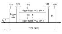
- the transmitting STAmay perform channel access through contending (ie, backoff operation) and transmit a trigger frame 1030 . That is, the transmitting STA (eg, AP) may transmit the PPDU including the Trigger Frame 1330 .
- a TB (trigger-based) PPDUis transmitted after a delay of SIFS.
- the TB PPDUs 1041 and 1042are transmitted in the same time zone, and may be transmitted from a plurality of STAs (eg, user STAs) in which AIDs are indicated in the trigger frame 1030 .
- the ACK frame 1050 for the TB PPDUmay be implemented in various forms.
- an orthogonal frequency division multiple access (OFDMA) technique or MU MIMO techniquemay be used, and OFDMA and MU MIMO technique may be used simultaneously.
- OFDMAorthogonal frequency division multiple access
- Each field shown in FIG. 6may be partially omitted, and another field may be added. Also, the length of each field may be changed differently from that shown.
- per user information fields 1160#1 to 1160#Ncorresponding to the number of receiving STAs receiving the trigger frame of FIG. 6 .
- the individual user information fieldmay be referred to as an 'allocation field'.
- the trigger frame of FIG. 6may include a padding field 1170 and a frame check sequence field 1180 .
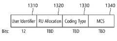
- Each of the per user information fields 1160#1 to 1160#N shown in FIG. 6may again include a plurality of subfields.
- the illustrated length field 1210has the same value as the length field of the L-SIG field of the uplink PPDU transmitted in response to the trigger frame, and the length field of the L-SIG field of the uplink PPDU indicates the length of the uplink PPDU.
- the length field 1210 of the trigger framemay be used to indicate the length of the corresponding uplink PPDU.
- the cascade indicator field 1220indicates whether a cascade operation is performed.
- the cascade operationmeans that downlink MU transmission and uplink MU transmission are performed together in the same TXOP. That is, after downlink MU transmission is performed, it means that uplink MU transmission is performed after a preset time (eg, SIFS).
- a preset timeeg, SIFS.
- the CS request field 1230indicates whether the state of the radio medium or NAV should be considered in a situation in which the receiving device receiving the corresponding trigger frame transmits the corresponding uplink PPDU.
- the HE-SIG-A information field 1240may include information for controlling the content of the SIG-A field (ie, the HE-SIG-A field) of the uplink PPDU transmitted in response to the corresponding trigger frame.
- the CP and LTF type field 1250may include information on the LTF length and CP length of the uplink PPDU transmitted in response to the corresponding trigger frame.
- the trigger type field 1060may indicate a purpose for which the corresponding trigger frame is used, for example, normal triggering, triggering for beamforming, a request for Block ACK/NACK, and the like.
- the trigger type field 1260 of the trigger frameindicates a basic type trigger frame for normal triggering.
- a basic type trigger framemay be referred to as a basic trigger frame.
- the subfield of FIG. 8may include a coding type field 1330 .
- the coding type field 1330may indicate the coding type of the TB PPDU. For example, when BCC coding is applied to the TB PPDU, the coding type field 1330 is set to '1', and when LDPC coding is applied, the coding type field 1330 is set to '0'. have.
- the subcarrier spacing of the L-STF, L-LTF, L-SIG, RL-SIG, U-SIG, and EHT-SIG fields of FIG. 9is set to 312.5 kHz, and the subcarrier spacing of the EHT-STF, EHT-LTF, and Data fields may be set to 78.125 kHz. That is, the tone index (or subcarrier index) of the L-STF, L-LTF, L-SIG, RL-SIG, U-SIG, and EHT-SIG fields is expressed in units of 312.5 kHz, EHT-STF, EHT-LTF, The tone index (or subcarrier index) of the Data field may be displayed in units of 78.125 kHz.
- L-LTF and L-STFmay be the same as the conventional fields.
- a universal SIG(U-SIG) may be inserted.
- the U-SIGmay be referred to by various names such as a first SIG field, a first SIG, a first type SIG, a control signal, a control signal field, and a first (type) control signal.
- the common field of the EHT-SIG and the user-individual field of the EHT-SIGmay be individually coded.
- One user block field included in the user-individual fieldmay contain information for two users, but the last user block field included in the user-individual field is for one user. It is possible to include information. That is, one user block field of the EHT-SIG may include a maximum of two user fields. As in the example of FIG. 6 , each user field may be related to MU-MIMO assignment or may be related to non-MU-MIMO assignment.
- the common field of the EHT-SIGmay include a CRC bit and a Tail bit, the length of the CRC bit may be determined as 4 bits, and the length of the Tail bit may be determined as 6 bits and may be set to '000000'.
- the common field of the EHT-SIGmay include RU allocation information.
- the RU allocation informationmay refer to information about a location of an RU to which a plurality of users (ie, a plurality of receiving STAs) are allocated. As in Table 1, RU allocation information may be configured in units of 8 bits (or N bits).
- (transmit/receive/uplink/downlink) signalmay be a signal transmitted/received based on the PPDU of FIG. 9 .
- the PPDU of FIG. 9may be used to transmit and receive various types of frames.
- the PPDU of FIG. 9may be used for a control frame.
- control framemay include request to send (RTS), clear to send (CTS), Power Save-Poll (PS-Poll), BlockACKReq, BlockAck, Null Data Packet (NDP) announcement, and Trigger Frame.
- the PPDU of FIG. 9may be used for a management frame.
- An example of the management framemay include a Beacon frame, a (Re-)Association Request frame, a (Re-)Association Response frame, a Probe Request frame, and a Probe Response frame.
- the PPDU of FIG. 9may be used for a data frame.
- the PPDU of FIG. 9may be used to simultaneously transmit at least two or more of a control frame, a management frame, and a data frame.
- FIG. 10shows a modified example of a transmitting apparatus and/or a receiving apparatus of the present specification.
- the processor 610 of FIG. 10may be the same as the processors 111 and 121 of FIG. 1 . Alternatively, the processor 610 of FIG. 10 may be the same as the processing chips 114 and 124 of FIG. 1 .
- the memory 150 of FIG. 10may be the same as the memories 112 and 122 of FIG. 1 .
- the memory 150 of FIG. 10may be a separate external memory different from the memories 112 and 122 of FIG. 1 .
- the speaker 640may output a sound related result processed by the processor 610 .
- Microphone 641may receive sound related input to be used by processor 610 .
- a trigger based (TB) physical protocol data unit (PPDU) of 11bepuncturing information may be indicated. That is, the TB PPDU may include puncturing information.
- the STA receiving the trigger framecannot determine puncturing information from the contents included in the existing trigger frame.
- the new informationmay be information included in a trigger frame to support EHT.
- the new informationmay include puncturing information, information related to whether 320 MHz is supported, and the like.
- FIG. 11is a diagram illustrating an example of a trigger frame.
- the existing bitsIn order to indicate additional information while maintaining the existing trigger frame format, the existing bits must be used while maintaining the total number of bits included in the trigger frame.
- the maximum UL (uplink) BW (bandwidth)is 160 MHz as in the conventional (ie, 11ax).
- the number of bitsmay be considered statically or dynamically according to the dependence of the UL bandwidth (BW) value of the Common field. That is, the number of bits related to the PI may be set to a constant value or may be changed according to the UL BW.
- BWUL bandwidth
- a bitmap indicating whether each 20 MHz segment is punctured independently(eg, puncturing if 1) may be used.
- the patternmay be indicated according to each value (eg, 0000 to 1001) using 4 bits.
- This embodimentis a method in which the number of PI bits is fixed, and will be described separately according to the indication methods A and B described above.
- the indication method Athat is, a bitmap independently indicating whether each 20 MHz segment is punctured
- the PHYeg, in U-SIG
- the Max PIThe bit becomes 4 bits
- the BW indicated by the PHYis up to 160 MHz
- the Max PI bitbecomes 8 bits.
- FIG. 12is a diagram illustrating one embodiment of method 1-1A.
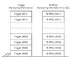
- the maximum (local) BWmay be 80 MHz, and the UL BW may also be 80 MHz. Since the maximum (local) BW is 80MHz, the number of bits is 4. Since the 3rd and 4th 20MHz segments are punctured, the PI may include bitmaps of 0011 and 0000, respectively. That is, the PI of the trigger frame transmitted in the 80 MHz band including the punctured region may include a bitmap of 0011, and the PI of the trigger frame transmitted in the non-punctured 80 MHz band may include the bitmap of 0000. .
- the TB PPDUmay also include puncturing information in the U-SIG, and the puncturing information included in the U-SIG of the TB PPDU may also include bitmaps of 0011 and 0000, respectively.
- the TB PPDUmay also be transmitted through a channel in which the 3rd and 4th 20MHz segments are punctured.
- Instruction method Bthat is, when a puncturing pattern is defined and an index corresponding to each puncturing pattern is used, the (local) BW indicated by the PHY (eg, in U-SIG) is up to 80 MHz, and 40 MHz If 2 puncturing patterns are defined in , and 3 puncturing patterns are defined at 80MHz, the Max PI bit is 3 bits because the total number of patterns is 5.
- 15is a diagram illustrating an embodiment of the 1-1B method.
- the maximum (local) BWmay be 80 MHz, and the UL BW may also be 80 MHz.
- the number of PI bitsmay be 3.
- the PI of the trigger framemay include a bitmap of 010, 000, respectively. That is, the PI of the trigger frame transmitted in the 80 MHz band including the punctured region may include a bitmap of 010, and the PI of the trigger frame transmitted in the non-punctured 80 MHz band may include the bitmap of 000. .
- the TB PPDUmay also include puncturing information in the U-SIG, and the puncturing information included in the U-SIG of the TB PPDU may also include a bitmap of 010, 000, respectively.
- the TB PPDUmay also be transmitted through the channel in which the second 20MHz segment is punctured.
- the number of PI bitsmay vary according to the UL BW value.
- Indicating method Athat is, when using a bitmap independently indicating whether or not each 20MHz segment is punctured, 8 bits if UL BW is 160MHz and 4 bits if 80MHz
- Instruction method Bthat is, if a puncturing pattern is defined and an index corresponding to each puncturing pattern is used, if two puncturing patterns are defined at 40 MHz and three puncturing patterns are defined at 80 MHz, PI is In the case of 1 bit, in the case of 80 MHz, it may be 2 bits.
- the example in which the UL BW of 1-2) is 160 MHzis the same as the example of FIG. 12 in which the maximum local BW is 160 MHz, only the number of bits of the PI may be dynamically changed. For example, if the maximum Max (local) BW: 160 MHz and the UL BW of the trigger frame is 80 MHz, the number of bits of the PI may be 4 bits, unlike the 8 bits of the bitmap example of FIG. 12 .
- the existing bitsIn order to indicate additional information while maintaining the existing trigger frame format, the existing bits must be used while maintaining the total number of bits.
- information for a 320 MHz BWmay be included in addition to a bit for the existing UL BW.
- This embodimentmay include a wider bandwidth (eg, information indicating bandwidth extension, bandwidth extension information) indication in addition to the method of clause 1.
- a wider bandwidtheg, information indicating bandwidth extension, bandwidth extension information
- the Wider bandwidthmay be indicated using the HE-SIG-A2 reserved field or Reserved bit, and the method in 4.1 may be used as a method of indicating the PI.
- an indication method according to a puncturing pattern(instruction method B of section 1) may be used.
- the maximum (local) BWmay be 320 MHz, and the UL BW may also be 320 MHz.
- the number of PI bitsmay be 5.
- the PI of the trigger framemay include 1 bit (1) related to the 320 MHz bandwidth.
- the PI of the trigger framemay include a bitmap of 100110. If the 3rd and 4th 20MHz segments of the Primary 160MHz are punctured and the index of the punctured patterns of the 1st and 2nd 20MHz segments of the Secondary 160Mhz is 00110, the PI of the trigger frame may include a bitmap of 00110.
- the PI of the trigger frameincludes the 100110 bitmap, it may mean that the 3rd, 4th, 9th, and 10th 20MHz segments among 320MHz are punctured. That is, the first bit may be related to the 320 MHz bandwidth, and the last 5 bits may be related to the puncturing pattern.
- the TB PPDUmay also include puncturing information in the U-SIG, and the puncturing information included in the U-SIG of the TB PPDU may also include a bitmap of 00110.
- the TB PPDUmay also be transmitted through channels in which the 3rd, 4th, 9th, and 10th 20MHz segments are punctured.
- an additional wider bandwidth and PIare indicated using the trigger dependent common field.
- Information on Primary 160 among 320MHzcan be indicated using the methods defined in Section 1. That is, PI for Wider bandwidth and Secondary 160 uses the dependent field.
- Wider bandwidth indicationuse 1 bit (for example, 320MHz if 1)
- instruction method Bthe interpretation may be different depending on the method. This is covered in the example below.
- FIG. 17is a diagram illustrating an embodiment of a trigger frame/TB PPDU transmitted through a 320 MHz bandwidth in an indication method A. Referring to FIG.
- the maximum (local) BWmay be 320 MHz, and the UL BW may also be 320 MHz. Since the maximum UL BW is 320MHz, the number of bits is 16.
- 1 bit (1) related to the 320 MHz bandwidthmay be additionally included.
- the PI of the trigger framemay include a bitmap of 00110000 111000000.
- the PI of the trigger framemay include a bitmap of 00110000 or 1100000. 1 bit related to the 320 MHz bandwidth may be included in the beginning of the bitmap for the secondary 160 MHz. That is, if the PI of the trigger frame includes the 00110000 111000000 bitmap, it may mean that the 3rd, 4th, 9th, and 10th 20MHz segments among 320MHz are punctured. That is, the ninth bit may be related to the 320 MHz bandwidth, and the remaining bits may be related to the position of the punctured 20 MHz segment.
- FIG. 18is a diagram illustrating an embodiment of a trigger frame/TB PPDU transmitted through a 320 MHz bandwidth in an indication method B. Referring to FIG.
- 0100 and 0011(except 1 bit indicating wider bandwidth) can be interpreted differently depending on the method.
- a total of 8 bits of 01000011represents a pattern obtained by puncturing the 3rd, 4th, 9th, and 10th 20MHz segments among the 320MHz puncturing patterns.
- 0100may indicate a pattern in which the 3rd and 4th 20MHz segments are punctured in the Primary 160
- 0011may indicate a pattern in which the 1st and 2nd 20MHz segments are punctured in the Secondary 160.
- Wider bandwidth indicationuse 1 bit (for example, 320MHz if 1, 240MHz if 0)
- the existing bitsIn order to indicate additional information while maintaining the existing trigger frame format, the existing bits must be used. In addition, in order to indicate the UL BW of 160 MHz or higher, for example, 320 MHz, it is necessary to include additional information in addition to the bits of the existing UL BW.
- the Common fieldis mainly used, and if other information than 11ax is put in the reserved bit existing in the Common field, a malfunction may occur if this Trigger frame is transmitted to the STA supporting 11ax.
- the STA supporting 11axmay define a specific User Info field that reads only 11be STAs without reading it, and 11be STAs may obtain specific information through these fields.
- the fields of User info for a specific AIDmay be maintained as they are, or may be modified because they are only for 11be STAs.
- User info for a specific AIDmay include puncturing information (PI).
- PIpuncturing information
- a field indicating that a specific AID existsmay be included in the common field of the trigger frame.
- the reserved bit of the common fieldmay be used for the present field.
- the STAcan know whether special information according to a specific AID is included in the user info field based on the present field of the common field.
- the STAmay perform an operation to find the specific AID if special information according to a specific AID is included based on the present field, and if special information according to the specific AID is not included based on the present field You can only perform the behavior of finding your own AID without performing it.
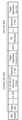
- 19is a diagram illustrating an embodiment of a method in which special information is included in a user info field related to a specific AID.
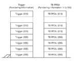
- the user info field in which the value of the AID12 field is set to 2047may include additional information for the 11be STA. That is, the specific AID12 value (eg, 2047, 2007, etc.) is a value through which the STA can view other additional information about the trigger (eg, PI, information related to the 320 MHz bandwidth, etc.). That is, the “1001100011000000” bitmap may be included in the user info field related to the value of a specific AID12 field, the first 1 of the bitmap is related to the 320 MHz bandwidth, and the rear “0011000011000000” is a 16-bit 20 MHz PI bitmap. can mean Here, if the UL BW of the Common field is indicated as 160 MHz, the 11be STA may first recognize this and recognize whether the bandwidth is 320 MHz through the user info field related to the specific AID 2047 of the User Info.
- the specific AID12 valueeg, 2047, 2007, etc.
- the “1001100011000000” bitmapmay be included
- a part of the trigger framemay be transmitted for an 11ax STA, and a part may be transmitted for an 11be STA.
- a trigger framemay be transmitted to STAs of 11ax (80 MHz above) and 11be (80 MHz below) with UL BW 160 MHz. Each may be separately transmitted with 80 MHz UL BW.
- common informationis the same in the entire 160 MHz band, and special information (eg, PI) may be transmitted to the 11be STA through a specific AID12 2047 in addition to the User Info field.
- special informationeg, PI
- the puncturing pattern in which the 7th and 8th 20MHz segments are puncturedmay be indicated by 010.
- 21is a diagram illustrating an embodiment of a method in which special information is included in a user info field related to a specific AID.
- the trigger framemay include a common info field and a user info field.
- the common info fieldmay include a present field (eg, a specific AID Present field) related to whether the user info field includes special information. That is, the common info field may have a present field indicating the existence of a specific AID12 (eg, 2407) of the user info field.
- the user info fieldmay include AID12 (eg, 2047) for special information.
- the special informationmay include puncturing information (PI) and/or information related to a 320 MHz bandwidth.
- the special informationmay include information for an STA supporting 11be or a standard after 11be.
- the value of AID12 related to special informationis not limited to the embodiment, and may have a value other than 2047 (eg, 2007, etc.).
- 22is a diagram illustrating an embodiment of a method of operating an STA.
- the STA operationmay be based on technical features described in at least one of FIGS. 1 to 21 .
- the STAmay receive the trigger frame (S2210).
- the STAmay receive a trigger frame from an access point (AP).
- the trigger framemay include a common information field and a user information field.
- the user information fieldmay include a first field related to an association identifier (AID) and a second field including information for an STA related to the AID.
- the second fieldmay include special information for all STAs receiving the trigger frame.
- the common information fieldmay include a present field related to whether a user information field having the specific value exists among the user information fields.
- the first fieldmay be an AID12 field.
- the second fieldmay be subfields of the user info field related to AID12.
- the special informationmay include information related to a 320 MHz uplink transmission bandwidth.
- the special informationmay include puncturing information
- the trigger framemay be transmitted through a punctured channel based on the puncturing information
- the puncturing informationmay include information related to whether puncturing is performed for each 20 MHz unit band.
- the puncturing informationmay include information related to an index corresponding to a preset puncturing pattern.
- the STAmay decode the trigger frame (S2220).
- the STAmay transmit a trigger-based PPDU (S2230).
- the STAmay transmit a trigger-based physical protocol data unit (PPDU) to the AP, and the trigger-based PPDU may be transmitted in a band based on the puncturing information.
- PPDUphysical protocol data unit
- 23is a diagram illustrating an embodiment of a method of operating an AP.
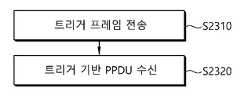
- the APmay transmit a trigger frame (S2310).
- the APmay transmit a trigger frame to a station (STA).
- the common information fieldmay include uplink transmission bandwidth information.
- the special informationmay include information related to a 320 MHz uplink transmission bandwidth.
- the special informationmay include puncturing information
- the trigger framemay be transmitted through a punctured channel based on the puncturing information
- the puncturing informationmay include information related to whether puncturing is performed for each 20 MHz unit band.
- the puncturing informationmay include information related to an index corresponding to a preset puncturing pattern.
- the APmay receive a trigger-based PPDU (S2320).
- the APmay receive a trigger-based physical protocol data unit (PPDU) from the STA in response to the trigger frame.
- PPDUphysical protocol data unit
- Some of the detailed steps shown in the example of FIGS. 22 and 23may not be essential steps and may be omitted. In addition to the steps shown in FIGS. 22 and 23 , other steps may be added, and the order of the steps may vary. Some of the above steps may have their own technical meaning.
- the technical features of the present specification described abovemay be applied to various devices and methods.
- the above-described technical features of the present specificationmay be performed/supported through the apparatus of FIGS. 1 and/or 10 .
- the technical features of the present specification described abovemay be applied only to a part of FIGS. 1 and/or 10 .
- the technical features of the present specification described aboveare implemented based on the processing chips 114 and 124 of FIG. 1 , or implemented based on the processors 111 and 121 and the memories 112 and 122 of FIG. 1 , or , may be implemented based on the processor 610 and the memory 620 of FIG. 10 .
- CRMcomputer readable medium
- STAstation
- wireless local area networkWireless Local Area Network
- the trigger frameis received from an access point (AP), the trigger frame including a common information field and a user information field, , the user information field includes a first field related to an association identifier (AID) and a second field including information for an STA related to the AID, and based on the fact that the first field has a specific value, the second field
- the fieldincludes special information for all STAs receiving the trigger frame, and the common information field is a present related to whether or not a user information field in which the first field has the specific value among the user information fields exists. ) field; and an instruction for performing an operation including decoding the trigger frame.
- the instructions stored in the CRM of the present specificationmay be executed by at least one processor.
- At least one processor related to CRM in the present specificationmay be the processors 111 and 121 or the processing chips 114 and 124 of FIG. 1 , or the processor 610 of FIG. 10 .
- the CRM of the present specificationmay be the memories 112 and 122 of FIG. 1 , the memory 620 of FIG. 10 , or a separate external memory/storage medium/disk.
- Machine learningrefers to a field that defines various problems dealt with in the field of artificial intelligence and studies methodologies to solve them. do.
- Machine learningis also defined as an algorithm that improves the performance of a certain task through constant experience.
- An artificial neural networkis a model used in machine learning, and may refer to an overall model having problem-solving ability, which is composed of artificial neurons (nodes) that form a network by combining synapses.
- An artificial neural networkmay be defined by a connection pattern between neurons of different layers, a learning process that updates model parameters, and an activation function that generates an output value.
- Machine learningcan be classified into supervised learning, unsupervised learning, and reinforcement learning according to a learning method.
- machine learningimplemented as a deep neural network (DNN) including a plurality of hidden layers is also called deep learning (deep learning), and deep learning is a part of machine learning.
- DNNdeep neural network
- deep learningdeep learning
- machine learningis used in a sense including deep learning.
- Robotscan be classified into industrial, medical, home, military, etc. depending on the purpose or field of use.
- the robotmay be provided with a driving unit including an actuator or a motor to perform various physical operations such as moving the robot joints.
- the movable robotincludes a wheel, a brake, a propeller, and the like in the driving unit, and can travel on the ground or fly in the air through the driving unit.
- the extended realityis a generic term for virtual reality (VR), augmented reality (AR), and mixed reality (MR).
- VR technologyprovides only CG images of objects or backgrounds in the real world
- AR technologyprovides virtual CG images on top of images of real objects
- MR technologyis a computer that mixes and combines virtual objects in the real world. graphic technology.
- MR technologyis similar to AR technology in that it shows both real and virtual objects. However, there is a difference in that in AR technology, a virtual object is used in a form that complements a real object, whereas in MR technology, a virtual object and a real object are used with equal characteristics.
- HMDHead-Mount Display
- HUDHead-Up Display
- mobile phonetablet PC, laptop, desktop, TV, digital signage, etc.
Landscapes
- Engineering & Computer Science (AREA)
- Signal Processing (AREA)
- Computer Networks & Wireless Communication (AREA)
- Quality & Reliability (AREA)
- Mobile Radio Communication Systems (AREA)
Abstract
Description
Translated fromKorean본 명세서는 무선랜(wireless local area network) 시스템에서 트리거 프레임을 전송하는 방법에 관한 것으로, 보다 상세하게는 트리거 프레임에 포함되는 정보 및 트리거 프레임 기반의 동작에 관한 것이다.The present specification relates to a method of transmitting a trigger frame in a wireless local area network (WLAN) system, and more particularly, to information included in the trigger frame and an operation based on the trigger frame.
WLAN(wireless local area network)은 다양한 방식으로 개선되어 왔다. 예를 들어, IEEE 802.11ax 표준은 OFDMA(orthogonal frequency division multiple access) 및 DL MU MIMO(downlink multi-user multiple input, multiple output) 기법을 사용하여 개선된 통신 환경을 제안했다.BACKGROUND Wireless local area networks (WLANs) have been improved in various ways. For example, the IEEE 802.11ax standard proposes an improved communication environment using OFDMA (orthogonal frequency division multiple access) and DL MU downlink multi-user multiple input, multiple output (MIMO) techniques.
본 명세서는 새로운 통신 표준에서 활용 가능한 기술적 특징을 제안한다. 예를 들어, 새로운 통신 표준은 최근에 논의 중인 EHT(extreme high throughput) 규격일 수 있다. EHT 규격은 새롭게 제안되는 증가된 대역폭, 개선된 PPDU(PHY layer protocol data unit) 구조, 개선된 시퀀스, HARQ(hybrid automatic repeat request) 기법 등을 사용할 수 있다. EHT 규격은 IEEE 802.11be 규격으로 불릴 수 있다.This specification proposes technical features that can be used in a new communication standard. For example, the new communication standard may be an extreme high throughput (EHT) standard that is being discussed recently. The EHT standard may use a newly proposed increased bandwidth, an improved PHY layer protocol data unit (PPDU) structure, an improved sequence, a hybrid automatic repeat request (HARQ) technique, and the like. The EHT standard may be referred to as an IEEE 802.11be standard.
다양한 실시 예들에 따른 무선랜(Wireless Local Area Network) 시스템에서 STA은 AP로부터, 트리거 프레임(trigger frame)을 수신할 수 있다. 상기 트리거 프레임은, 공통 정보 필드 및 유저 정보 필드를 포함할 수 있다. 상기 유저 정보 필드는 AID(association identifier)에 관련된 제1 필드 및 상기 AID에 관련된 STA을 위한 정보를 포함하는 제2 필드를 포함할 수 있다. 상기 제1 필드가 특정 값을 가지는 것을 기초로 상기 제2 필드는 상기 트리거 프레임을 수신하는 모든 STA을 위한 특별 정보를 포함할 수 있다. 상기 공통 정보 필드는 유저 정보 필드 중에서 상기 제1 필드가 상기 특정 값을 가지는 유저 정보 필드가 존재하는지 여부에 관련된 프레젠트(present) 필드를 포함할 수 있다.In a wireless local area network (WLAN) system according to various embodiments, the STA may receive a trigger frame from the AP. The trigger frame may include a common information field and a user information field. The user information field may include a first field related to an association identifier (AID) and a second field including information for an STA related to the AID. Based on the fact that the first field has a specific value, the second field may include special information for all STAs receiving the trigger frame. The common information field may include a present field related to whether a user information field having the specific value of the first field among the user information fields exists.
본 명세서의 일례에 따르면, 기존 Trigger frame의 포맷을 그대로 사용하면서 trigger frame에 포함되는 정보의 양을 늘릴 수 있다. 특정 AID에 해당하는 유저 필드에 11be feature에 관련된 정보가 포함되므로 backward compatibility에도 문제 없고, forward compatibility 확보에도 유리하다. 즉 이후 표준에서도 특별 정보에 관련되는 AID를 새로 설정하면 되기 때문에, 차세대 표준을 위해 계속 사용될 수 있다.According to an example of the present specification, it is possible to increase the amount of information included in the trigger frame while using the format of the existing trigger frame as it is. Since the information related to the 11be feature is included in the user field corresponding to a specific AID, there is no problem in backward compatibility and it is advantageous in securing forward compatibility. That is, since the AID related to special information needs to be newly set in a later standard, it can continue to be used for a next-generation standard.
도 1은 본 명세서의 송신 장치 및/또는 수신 장치의 일례를 나타낸다.1 shows an example of a transmitting apparatus and/or a receiving apparatus of the present specification.
도 2는 무선랜(WLAN)의 구조를 나타낸 개념도이다.2 is a conceptual diagram illustrating the structure of a wireless local area network (WLAN).
도 3은 일반적인 링크 셋업(link setup) 과정을 설명하는 도면이다.3 is a view for explaining a general link setup process.
도 4은 80MHz 대역 상에서 사용되는 자원유닛(RU)의 배치를 나타내는 도면이다.4 is a diagram illustrating an arrangement of resource units (RUs) used on an 80 MHz band.
도 5은 UL-MU에 따른 동작을 나타낸다.5 shows an operation according to UL-MU.
도 6은 트리거 프레임의 일례를 나타낸다.6 shows an example of a trigger frame.
도 7는 트리거 프레임의 공통 정보(common information) 필드의 일례를 나타낸다.7 shows an example of a common information field of a trigger frame.
도 8은 사용자 정보(per user information) 필드에 포함되는 서브 필드의 일례를 나타낸다.8 shows an example of a subfield included in a per user information field.
도 9은 본 명세서에 사용되는 PPDU의 일례를 나타낸다.9 shows an example of a PPDU used in this specification.
도 10는 본 명세서의 송신 장치 및/또는 수신 장치의 변형된 일례를 나타낸다.10 shows a modified example of a transmitting apparatus and/or a receiving apparatus of the present specification.
도 11은 트리거 프레임의 일례를 도시한 도면이다.11 is a diagram illustrating an example of a trigger frame.
도 12는 1-1A 방법의 일 실시예를 도시한 도면이다.12 is a diagram illustrating one embodiment of method 1-1A.
도 13은 1-1A 방법의 일 실시예를 도시한 도면이다.13 is a diagram illustrating one embodiment of method 1-1A.
도 14는 1-1B 방법의 일 실시예를 도시한 도면이다.14 is a diagram illustrating an embodiment of the 1-1B method.
도 15는 1-1B 방법의 일 실시예를 도시한 도면이다.15 is a diagram illustrating an embodiment of the 1-1B method.
도 16은 지시 방법 B로 320MHz 대역폭을 통해 전송되는 트리거 프레임/TB PPDU의 일 실시예를 도시한 도면이다.16 is a diagram illustrating an embodiment of a trigger frame/TB PPDU transmitted through a 320 MHz bandwidth in an indication method B. Referring to FIG.
도 17은 지시 방법 A로 320MHz 대역폭을 통해 전송되는 트리거 프레임/TB PPDU의 일 실시예를 도시한 도면이다.17 is a diagram illustrating an embodiment of a trigger frame/TB PPDU transmitted through a 320 MHz bandwidth in an indication method A. Referring to FIG.
도 18은 지시 방법 B로 320MHz 대역폭을 통해 전송되는 트리거 프레임/TB PPDU의 일 실시예를 도시한 도면이다.18 is a diagram illustrating an embodiment of a trigger frame/TB PPDU transmitted through a 320 MHz bandwidth in an indication method B. Referring to FIG.
도 19는 특정 AID에 관련된 user info 필드에 특별 정보가 포함되는 방법의 일 실시예를 도시한 도면이다.19 is a diagram illustrating an embodiment of a method in which special information is included in a user info field related to a specific AID.
도 20은 특정 AID에 관련된 user info 필드에 특별 정보가 포함되는 방법의 일 실시예를 도시한 도면이다.20 is a diagram illustrating an embodiment of a method in which special information is included in a user info field related to a specific AID.
도 21은 특정 AID에 관련된 user info 필드에 특별 정보가 포함되는 방법의 일 실시예를 도시한 도면이다.21 is a diagram illustrating an embodiment of a method in which special information is included in a user info field related to a specific AID.
도 22는 STA 동작 방법의 일 실시예를 도시한 도면이다.22 is a diagram illustrating an embodiment of a method of operating an STA.
도 23은 AP 동작 방법의 일 실시예를 도시한 도면이다.23 is a diagram illustrating an embodiment of a method of operating an AP.
본 명세서에서 'A 또는 B(A or B)'는 '오직 A', '오직 B' 또는 'A와 B 모두'를 의미할 수 있다. 달리 표현하면, 본 명세서에서 'A 또는 B(A or B)'는 'A 및/또는 B(A and/or B)'으로 해석될 수 있다. 예를 들어, 본 명세서에서 'A, B 또는 C(A, B or C)'는 '오직 A', '오직 B', '오직 C', 또는 'A, B 및 C의 임의의 모든 조합(any combination of A, B and C)'를 의미할 수 있다.In this specification, 'A or B (A or B)' may mean 'only A', 'only B', or 'both A and B'. In other words, 'A or B (A or B)' in the present specification may be interpreted as 'A and/or B (A and/or B)'. For example, 'A, B or C(A, B or C)' as used herein means 'only A', 'only B', 'only C', or 'any and any combination of A, B and C ( It may mean any combination of A, B and C).
본 명세서에서 사용되는 슬래쉬(/)나 쉼표(comma)는 '및/또는(and/or)'을 의미할 수 있다. 예를 들어, 'A/B'는 'A 및/또는 B'를 의미할 수 있다. 이에 따라 'A/B'는 '오직 A', '오직 B', 또는 'A와 B 모두'를 의미할 수 있다. 예를 들어, 'A, B, C'는 'A, B 또는 C'를 의미할 수 있다.A slash (/) or a comma (comma) used herein may mean 'and/or'. For example, 'A/B' may mean 'A and/or B'. Accordingly, 'A/B' may mean 'only A', 'only B', or 'both A and B'. For example, 'A, B, C' may mean 'A, B, or C'.
본 명세서에서 '적어도 하나의 A 및 B(at least one of A and B)'는, '오직 A', '오직 B' 또는 'A와 B 모두'를 의미할 수 있다. 또한, 본 명세서에서 '적어도 하나의 A 또는 B(at least one of A or B)'나 '적어도 하나의 A 및/또는 B(at least one of A and/or B)'라는 표현은 '적어도 하나의 A 및 B(at least one of A and B)'와 동일하게 해석될 수 있다.In the present specification, 'at least one of A and B' may mean 'only A', 'only B', or 'both A and B'. In addition, in this specification, the expression 'at least one of A or B' or 'at least one of A and/or B' means 'at least one It can be interpreted the same as 'A and B (at least one of A and B)'.
또한, 본 명세서에서 '적어도 하나의 A, B 및 C(at least one of A, B and C)'는, '오직 A', '오직 B', '오직 C', 또는 'A, B 및 C의 임의의 모든 조합(any combination of A, B and C)'를 의미할 수 있다. 또한, '적어도 하나의 A, B 또는 C(at least one of A, B or C)'나 '적어도 하나의 A, B 및/또는 C(at least one of A, B and/or C)'는 '적어도 하나의 A, B 및 C(at least one of A, B and C)'를 의미할 수 있다.Also, as used herein, 'at least one of A, B and C' means 'only A', 'only B', 'only C', or 'A, B and C' It may mean any combination of A, B and C'. In addition, 'at least one of A, B or C' or 'at least one of A, B and/or C' means It may mean 'at least one of A, B and C'.
또한, 본 명세서에서 사용되는 괄호는 '예를 들어(for example)'를 의미할 수 있다. 구체적으로, '제어 정보(EHT-Signal)'로 표시된 경우, '제어 정보'의 일례로 'EHT-Signal'이 제안된 것일 수 있다. 달리 표현하면 본 명세서의 '제어 정보'는 'EHT-Signal'로 제한(limit)되지 않고, 'EHT-Signal'이 '제어 정보'의 일례로 제안될 것일 수 있다. 또한, '제어 정보(즉, EHT-signal)'로 표시된 경우에도, '제어 정보'의 일례로 'EHT-signal'가 제안된 것일 수 있다.In addition, parentheses used herein may mean 'for example'. Specifically, when 'control information (EHT-Signal)' is displayed, 'EHT-Signal' may be proposed as an example of 'control information'. In other words, 'control information' of the present specification is not limited to 'EHT-Signal', and 'EHT-Signal' may be suggested as an example of 'control information'. Also, even when displayed as 'control information (ie, EHT-signal)', 'EHT-signal' may be proposed as an example of 'control information'.
본 명세서에서 하나의 도면 내에서 개별적으로 설명되는 기술적 특징은, 개별적으로 구현될 수도 있고, 동시에 구현될 수도 있다.In this specification, technical features that are individually described within one drawing may be implemented individually or simultaneously.
본 명세서의 이하의 일례는 다양한 무선 통신시스템에 적용될 수 있다. 예를 들어, 본 명세서의 이하의 일례는 무선랜(wireless local area network, WLAN) 시스템에 적용될 수 있다. 예를 들어, 본 명세서는 IEEE 802.11a/g/n/ac의 규격이나, IEEE 802.11ax 규격에 적용될 수 있다. 또한 본 명세서는 새롭게 제안되는 EHT 규격 또는 IEEE 802.11be 규격에도 적용될 수 있다. 또한 본 명세서의 일례는 EHT 규격 또는 IEEE 802.11be를 개선(enhance)한 새로운 무선랜 규격에도 적용될 수 있다. 또한 본 명세서의 일례는 이동 통신 시스템에 적용될 수 있다. 예를 들어, 3GPP(3rd Generation Partnership Project) 규격에 기반하는 LTE(Long Term Evolution) 및 그 진화(evoluation)에 기반하는 이동 통신 시스템에 적용될 수 있다. 또한, 본 명세서의 일례는 3GPP 규격에 기반하는 5G NR 규격의 통신 시스템에 적용될 수 있다.The following examples of the present specification may be applied to various wireless communication systems. For example, the following example of the present specification may be applied to a wireless local area network (WLAN) system. For example, the present specification may be applied to the IEEE 802.11a/g/n/ac standard or the IEEE 802.11ax standard. In addition, this specification may be applied to a newly proposed EHT standard or IEEE 802.11be standard. In addition, an example of the present specification may be applied to the EHT standard or a new wireless LAN standard that is an enhancement of IEEE 802.11be. Also, an example of the present specification may be applied to a mobile communication system. For example, it may be applied to a mobile communication system based on Long Term Evolution (LTE) based on the 3rd Generation Partnership Project (3GPP) standard and its evolution. In addition, an example of the present specification may be applied to a communication system of the 5G NR standard based on the 3GPP standard.
이하 본 명세서의 기술적 특징을 설명하기 위해 본 명세서가 적용될 수 있는 기술적 특징을 설명한다.Hereinafter, technical features to which the present specification can be applied in order to describe the technical features of the present specification will be described.
도 1은 본 명세서의 송신 장치 및/또는 수신 장치의 일례를 나타낸다.1 shows an example of a transmitting apparatus and/or a receiving apparatus of the present specification.
도 1의 일례는 이하에서 설명되는 다양한 기술적 특징을 수행할 수 있다. 도 1은 적어도 하나의 STA(station)에 관련된다. 예를 들어, 본 명세서의 STA(110, 120)은 이동 단말(mobile terminal), 무선 기기(wireless device), 무선 송수신 유닛(Wireless Transmit/Receive Unit; WTRU), 사용자 장비(User Equipment; UE), 이동국(Mobile Station; MS), 이동 가입자 유닛(Mobile Subscriber Unit) 또는 단순히 유저(user) 등의 다양한 명칭으로도 불릴 수 있다. 본 명세서의 STA(110, 120)은 네트워크, 기지국(Base Station), Node-B, AP(Access Point), 리피터, 라우터, 릴레이 등의 다양한 명칭으로 불릴 수 있다. 본 명세서의 STA(110, 120)은 수신 장치(apparatus), 송신 장치, 수신 STA, 송신 STA, 수신 Device, 송신 Device 등의 다양한 명칭으로 불릴 수 있다.The example of FIG. 1 may perform various technical features described below. 1 relates to at least one STA (station). For example, the
예를 들어, STA(110, 120)은 AP(access Point) 역할을 수행하거나 non-AP 역할을 수행할 수 있다. 즉, 본 명세서의 STA(110, 120)은 AP 및/또는 non-AP의 기능을 수행할 수 있다. 본 명세서에서 AP는 AP STA으로도 표시될 수 있다.For example, the
본 명세서의 STA(110, 120)은 IEEE 802.11 규격 이외의 다양한 통신 규격을 함께 지원할 수 있다. 예를 들어, 3GPP 규격에 따른 통신 규격(예를 들어, LTE, LTE-A, 5G NR 규격)등을 지원할 수 있다. 또한 본 명세서의 STA은 휴대 전화, 차량(vehicle), 개인용 컴퓨터 등의 다양한 장치로 구현될 수 있다. 또한, 본 명세서의 STA은 음성 통화, 영상 통화, 데이터 통신, 자율 주행(Self-Driving, Autonomous-Driving) 등의 다양한 통신 서비스를 위한 통신을 지원할 수 있다.The
본 명세서에서 STA(110, 120)은 IEEE 802.11 표준의 규정을 따르는 매체 접속 제어(medium access control, MAC)와 무선 매체에 대한 물리 계층(Physical Layer) 인터페이스를 포함할 수 있다.In the present specification, the
도 1의 부도면 (a)를 기초로 STA(110, 120)을 설명하면 이하와 같다.The
제1 STA(110)은 프로세서(111), 메모리(112) 및 트랜시버(113)를 포함할 수 있다. 도시된 프로세서, 메모리 및 트랜시버는 각각 별도의 칩으로 구현되거나, 적어도 둘 이상의 블록/기능이 하나의 칩을 통해 구현될 수 있다.The
제1 STA의 트랜시버(113)는 신호의 송수신 동작을 수행한다. 구체적으로, IEEE 802.11 패킷(예를 들어, IEEE 802.11a/b/g/n/ac/ax/be 등)을 송수신할 수 있다.The
예를 들어, 제1 STA(110)은 AP의 의도된 동작을 수행할 수 있다. 예를 들어, AP의 프로세서(111)는 트랜시버(113)를 통해 신호를 수신하고, 수신 신호를 처리하고, 송신 신호를 생성하고, 신호 송신을 위한 제어를 수행할 수 있다. AP의 메모리(112)는 트랜시버(113)를 통해 수신된 신호(즉, 수신 신호)를 저장할 수 있고, 트랜시버를 통해 송신될 신호(즉, 송신 신호)를 저장할 수 있다.For example, the
예를 들어, 제2 STA(120)은 Non-AP STA의 의도된 동작을 수행할 수 있다. 예를 들어, non-AP의 트랜시버(123)는 신호의 송수신 동작을 수행한다. 구체적으로, IEEE 802.11 패킷(예를 들어, IEEE 802.11a/b/g/n/ac/ax/be 등)을 송수신할 수 있다.For example, the
예를 들어, Non-AP STA의 프로세서(121)는 트랜시버(123)를 통해 신호를 수신하고, 수신 신호를 처리하고, 송신 신호를 생성하고, 신호 송신을 위한 제어를 수행할 수 있다. Non-AP STA의 메모리(122)는 트랜시버(123)를 통해 수신된 신호(즉, 수신 신호)를 저장할 수 있고, 트랜시버를 통해 송신될 신호(즉, 송신 신호)를 저장할 수 있다.For example, the
예를 들어, 이하의 명세서에서 AP로 표시된 장치의 동작은 제1 STA(110) 또는 제2 STA(120)에서 수행될 수 있다. 예를 들어 제1 STA(110)이 AP인 경우, AP로 표시된 장치의 동작은 제1 STA(110)의 프로세서(111)에 의해 제어되고, 제1 STA(110)의 프로세서(111)에 의해 제어되는 트랜시버(113)를 통해 관련된 신호가 송신되거나 수신될 수 있다. 또한, AP의 동작에 관련된 제어 정보나 AP의 송신/수신 신호는 제1 STA(110)의 메모리(112)에 저장될 수 있다. 또한, 제2 STA(110)이 AP인 경우, AP로 표시된 장치의 동작은 제2 STA(120)의 프로세서(121)에 의해 제어되고, 제2 STA(120)의 프로세서(121)에 의해 제어되는 트랜시버(123)를 통해 관련된 신호가 송신되거나 수신될 수 있다. 또한, AP의 동작에 관련된 제어 정보나 AP의 송신/수신 신호는 제2 STA(110)의 메모리(122)에 저장될 수 있다.For example, an operation of a device denoted as an AP in the following specification may be performed by the
예를 들어, 이하의 명세서에서 non-AP(또는 User-STA)로 표시된 장치의 동작은 제 STA(110) 또는 제2 STA(120)에서 수행될 수 있다. 예를 들어 제2 STA(120)이 non-AP인 경우, non-AP로 표시된 장치의 동작은 제2 STA(120)의 프로세서(121)에 의해 제어되고, 제2 STA(120)의 프로세서(121)에 의해 제어되는 트랜시버(123)를 통해 관련된 신호가 송신되거나 수신될 수 있다. 또한, non-AP의 동작에 관련된 제어 정보나 AP의 송신/수신 신호는 제2 STA(120)의 메모리(122)에 저장될 수 있다. 예를 들어 제1 STA(110)이 non-AP인 경우, non-AP로 표시된 장치의 동작은 제1 STA(110)의 프로세서(111)에 의해 제어되고, 제1 STA(120)의 프로세서(111)에 의해 제어되는 트랜시버(113)를 통해 관련된 신호가 송신되거나 수신될 수 있다. 또한, non-AP의 동작에 관련된 제어 정보나 AP의 송신/수신 신호는 제1 STA(110)의 메모리(112)에 저장될 수 있다.For example, an operation of a device indicated as a non-AP (or User-STA) in the following specification may be performed by the
이하의 명세서에서 (송신/수신) STA, 제1 STA, 제2 STA, STA1, STA2, AP, 제1 AP, 제2 AP, AP1, AP2, (송신/수신) Terminal, (송신/수신) device, (송신/수신) apparatus, 네트워크 등으로 불리는 장치는 도 1의 STA(110, 120)을 의미할 수 있다. 예를 들어, 구체적인 도면 부호 없이 (송신/수신) STA, 제1 STA, 제2 STA, STA1, STA2, AP, 제1 AP, 제2 AP, AP1, AP2, (송신/수신) Terminal, (송신/수신) device, (송신/수신) apparatus, 네트워크 등으로 표시된 장치도 도 1의 STA(110, 120)을 의미할 수 있다. 예를 들어, 이하의 일례에서 다양한 STA이 신호(예를 들어, PPPDU)를 송수신하는 동작은 도 1의 트랜시버(113, 123)에서 수행되는 것일 수 있다. 또한, 이하의 일례에서 다양한 STA이 송수신 신호를 생성하거나 송수신 신호를 위해 사전에 데이터 처리나 연산을 수행하는 동작은 도 1의 프로세서(111, 121)에서 수행되는 것일 수 있다. 예를 들어, 송수신 신호를 생성하거나 송수신 신호를 위해 사전에 데이터 처리나 연산을 수행하는 동작의 일례는, 1) PPDU 내에 포함되는 서브 필드(SIG, STF, LTF, Data) 필드의 비트 정보를 결정/획득/구성/연산/디코딩/인코딩하는 동작, 2) PPDU 내에 포함되는 서브 필드(SIG, STF, LTF, Data) 필드를 위해 사용되는 시간 자원이나 주파수 자원(예를 들어, 서브캐리어 자원) 등을 결정/구성/회득하는 동작, 3) PPDU 내에 포함되는 서브 필드(SIG, STF, LTF, Data) 필드를 위해 사용되는 특정한 시퀀스(예를 들어, 파일럿 시퀀스, STF/LTF 시퀀스, SIG에 적용되는 엑스트라 시퀀스) 등을 결정/구성/회득하는 동작, 4) STA에 대해 적용되는 전력 제어 동작 및/또는 파워 세이빙 동작, 5) ACK 신호의 결정/획득/구성/연산/디코딩/인코딩 등에 관련된 동작을 포함할 수 있다. 또한, 이하의 일례에서 다양한 STA이 송수신 신호의 결정/획득/구성/연산/디코딩/인코딩을 위해 사용하는 다양한 정보(예를 들어, 필드/서브필드/제어필드/파라미터/파워 등에 관련된 정보)는 도 1의 메모리(112, 122)에 저장될 수 있다.In the following specification (transmission / reception) STA, first STA, second STA, STA1, STA2, AP, first AP, second AP, AP1, AP2, (transmission / reception) Terminal, (transmission / reception) device , (transmission/reception) apparatus, network, and the like may refer to the
상술한 도 1의 부도면 (a)의 장치/STA는 도 1의 부도면 (b)와 같이 변형될 수 있다. 이하 도 1의 부도면 (b)을 기초로, 본 명세서의 STA(110, 120)을 설명한다.The device/STA of the sub-view (a) of FIG. 1 described above may be modified as shown in the sub-view (b) of FIG. 1 . Hereinafter, the
예를 들어, 도 1의 부도면 (b)에 도시된 트랜시버(113, 123)는 상술한 도 1의 부도면 (a)에 도시된 트랜시버와 동일한 기능을 수행할 수 있다. 예를 들어, 도 1의 부도면 (b)에 도시된 프로세싱 칩(114, 124)은 프로세서(111, 121) 및 메모리(112, 122)를 포함할 수 있다. 도 1의 부도면 (b)에 도시된 프로세서(111, 121) 및 메모리(112, 122)는 상술한 도 1의 부도면 (a)에 도시된 프로세서(111, 121) 및 메모리(112, 122)와 동일한 기능을 수행할 수 있다.For example, the
이하에서 설명되는, 이동 단말(mobile terminal), 무선 기기(wireless device), 무선 송수신 유닛(Wireless Transmit/Receive Unit; WTRU), 사용자 장비(User Equipment; UE), 이동국(Mobile Station; MS), 이동 가입자 유닛(Mobile Subscriber Unit), 유저(user), 유저 STA, 네트워크, 기지국(Base Station), Node-B, AP(Access Point), 리피터, 라우터, 릴레이, 수신 장치, 송신 장치, 수신 STA, 송신 STA, 수신 Device, 송신 Device, 수신 Apparatus, 및/또는 송신 Apparatus는, 도 1의 부도면 (a)/(b)에 도시된 STA(110, 120)을 의미하거나, 도 1의 부도면 (b)에 도시된 프로세싱 칩(114, 124)을 의미할 수 있다. 즉, 본 명세서의 기술적 특징은, 도 1의 부도면 (a)/(b)에 도시된 STA(110, 120)에 수행될 수도 있고, 도 1의 부도면 (b)에 도시된 프로세싱 칩(114, 124)에서만 수행될 수도 있다. 예를 들어, 송신 STA가 제어 신호를 송신하는 기술적 특징은, 도 1의 부도면 (a)/(b)에 도시된 프로세서(111, 121)에서 생성된 제어 신호가 도 1의 부도면 (a)/(b)에 도시된 트랜시버(113, 123)을 통해 송신되는 기술적 특징으로 이해될 수 있다. 또는, 송신 STA가 제어 신호를 송신하는 기술적 특징은, 도 1의 부도면 (b)에 도시된 프로세싱 칩(114, 124)에서 트랜시버(113, 123)로 전달될 제어 신호가 생성되는 기술적 특징으로 이해될 수 있다.As described below, a mobile terminal, a wireless device, a wireless transmit/receive unit (WTRU), a user equipment (UE), a mobile station (MS), a mobile Mobile Subscriber Unit, user, user STA, network, base station, Node-B, access point (AP), repeater, router, relay, receiving device, transmitting device, receiving STA, transmitting STA, Receiving Device, Transmitting Device, Receiving Apparatus, and/or Transmitting Apparatus means the
예를 들어, 수신 STA가 제어 신호를 수신하는 기술적 특징은, 도 1의 부도면 (a)에 도시된 트랜시버(113, 123)에 의해 제어 신호가 수신되는 기술적 특징으로 이해될 수 있다. 또는, 수신 STA가 제어 신호를 수신하는 기술적 특징은, 도 1의 부도면 (a)에 도시된 트랜시버(113, 123)에 수신된 제어 신호가 도 1의 부도면 (a)에 도시된 프로세서(111, 121)에 의해 획득되는 기술적 특징으로 이해될 수 있다. 또는, 수신 STA가 제어 신호를 수신하는 기술적 특징은, 도 1의 부도면 (b)에 도시된 트랜시버(113, 123)에 수신된 제어 신호가 도 1의 부도면 (b)에 도시된 프로세싱 칩(114, 124)에 의해 획득되는 기술적 특징으로 이해될 수 있다.For example, the technical feature in which the receiving STA receives the control signal may be understood as the technical feature in which the control signal is received by the
도 1의 부도면 (b)을 참조하면, 메모리(112, 122) 내에 소프트웨어 코드(115, 125)가 포함될 수 있다. 소프트웨어 코드(115, 125)는 프로세서(111, 121)의 동작을 제어하는 instruction이 포함될 수 있다. 소프트웨어 코드(115, 125)는 다양한 프로그래밍 언어로 포함될 수 있다.Referring to (b) of FIG. 1 ,
도 1에 도시된 프로세서(111, 121) 또는 프로세싱 칩(114, 124)은 ASIC(application-specific integrated circuit), 다른 칩셋, 논리 회로 및/또는 데이터 처리 장치를 포함할 수 있다. 프로세서는 AP(application processor)일 수 있다. 예를 들어, 도 1에 도시된 프로세서(111, 121) 또는 프로세싱 칩(114, 124)은 DSP(digital signal processor), CPU(central processing unit), GPU(graphics processing unit), 모뎀(Modem; modulator and demodulator) 중 적어도 하나를 포함할 수 있다. 예를 들어, 도 1에 도시된 프로세서(111, 121) 또는 프로세싱 칩(114, 124)은 Qualcomm®에 의해 제조된 SNAPDRAGONTM 시리즈 프로세서, Samsung®에 의해 제조된 EXYNOSTM 시리즈 프로세서, Apple®에 의해 제조된 A 시리즈 프로세서, MediaTek®에 의해 제조된 HELIOTM 시리즈 프로세서, INTEL®에 의해 제조된 ATOMTM 시리즈 프로세서 또는 이를 개선(enhance)한 프로세서일 수 있다.The
본 명세서에서 상향링크는 non-AP STA로부터 AP STA으로의 통신을 위한 링크를 의미할 수 있고 상향링크를 통해 상향링크 PPDU/패킷/신호 등이 송신될 수 있다. 또한, 본 명세서에서 하향링크는 AP STA로부터 non-AP STA으로의 통신을 위한 링크를 의미할 수 있고 하향링크를 통해 하향링크 PPDU/패킷/신호 등이 송신될 수 있다.In this specification, the uplink may mean a link for communication from the non-AP STA to the AP STA, and an uplink PPDU/packet/signal may be transmitted through the uplink. In addition, in the present specification, downlink may mean a link for communication from an AP STA to a non-AP STA, and a downlink PPDU/packet/signal may be transmitted through the downlink.
도 2는 무선랜(WLAN)의 구조를 나타낸 개념도이다.2 is a conceptual diagram illustrating the structure of a wireless local area network (WLAN).
도 2의 상단은 IEEE(institute of electrical and electronic engineers) 802.11의 인프라스트럭쳐 BSS(basic service set)의 구조를 나타낸다.The upper part of FIG. 2 shows the structure of an infrastructure basic service set (BSS) of the Institute of Electrical and Electronic Engineers (IEEE) 802.11.
도 2의 상단을 참조하면, 무선랜 시스템은 하나 또는 그 이상의 인프라스트럭쳐 BSS(200, 205)(이하, BSS)를 포함할 수 있다. BSS(200, 205)는 성공적으로 동기화를 이루어서 서로 통신할 수 있는 AP(access point, 225) 및 STA1(Station, 200-1)과 같은 AP와 STA의 집합으로서, 특정 영역을 가리키는 개념은 아니다. BSS(205)는 하나의 AP(230)에 하나 이상의 결합 가능한 STA(205-1, 205-2)을 포함할 수도 있다.Referring to the upper part of FIG. 2 , a wireless LAN system may include one or
BSS는 적어도 하나의 STA, 분산 서비스(distribution Service)를 제공하는 AP(225, 230) 및 다수의 AP를 연결시키는 분산 시스템(distribution System, DS, 210)을 포함할 수 있다.The BSS may include at least one STA, the
분산 시스템(210)은 여러 BSS(200, 205)를 연결하여 확장된 서비스 셋인 ESS(extended service set, 240)를 구현할 수 있다. ESS(240)는 하나 또는 여러 개의 AP가 분산 시스템(210)을 통해 연결되어 이루어진 하나의 네트워크를 지시하는 용어로 사용될 수 있다. 하나의 ESS(240)에 포함되는 AP는 동일한 SSID(service set identification)를 가질 수 있다.The distributed
포털(portal, 220)은 무선랜 네트워크(IEEE 802.11)와 다른 네트워크(예를 들어, 802.X)와의 연결을 수행하는 브리지 역할을 수행할 수 있다.The portal 220 may serve as a bridge connecting a wireless LAN network (IEEE 802.11) and another network (eg, 802.X).
도 2의 상단과 같은 BSS에서는 AP(225, 230) 사이의 네트워크 및 AP(225, 230)와 STA(200-1, 205-1, 205-2) 사이의 네트워크가 구현될 수 있다. 하지만, AP(225, 230)가 없이 STA 사이에서도 네트워크를 설정하여 통신을 수행하는 것도 가능할 수 있다. AP(225, 230)가 없이 STA 사이에서도 네트워크를 설정하여 통신을 수행하는 네트워크를 애드-혹 네트워크(Ad-Hoc network) 또는 독립 BSS(independent basic service set, IBSS)라고 정의한다.In the BSS as shown in the upper part of FIG. 2 , a network between the
도 2의 하단은 IBSS를 나타낸 개념도이다.The lower part of FIG. 2 is a conceptual diagram illustrating the IBSS.
도 2의 하단을 참조하면, IBSS는 애드-혹 모드로 동작하는 BSS이다. IBSS는 AP를 포함하지 않기 때문에 중앙에서 관리 기능을 수행하는 개체(centralized management entity)가 없다. 즉, IBSS에서 STA(250-1, 250-2, 250-3, 255-4, 255-5)들은 분산된 방식(distributed manner)으로 관리된다. IBSS에서는 모든 STA(250-1, 250-2, 250-3, 255-4, 255-5)이 이동 STA으로 이루어질 수 있으며, 분산 시스템으로의 접속이 허용되지 않아서 자기 완비적 네트워크(self-contained network)를 이룬다.Referring to the lower part of FIG. 2 , the IBSS is a BSS operating in an ad-hoc mode. Since IBSS does not include an AP, there is no centralized management entity that performs a centralized management function. That is, in the IBSS, the STAs 250-1, 250-2, 250-3, 255-4, and 255-5 are managed in a distributed manner. In IBSS, all STAs (250-1, 250-2, 250-3, 255-4, 255-5) can be mobile STAs, and access to a distributed system is not allowed, so a self-contained network network) is formed.
도 3은 일반적인 링크 셋업(link setup) 과정을 설명하는 도면이다.3 is a view for explaining a general link setup process.
도시된 S310 단계에서 STA은 네트워크 발견 동작을 수행할 수 있다. 네트워크 발견 동작은 STA의 스캐닝(scanning) 동작을 포함할 수 있다. 즉, STA이 네트워크에 액세스하기 위해서는 참여 가능한 네트워크를 찾아야 한다. STA은 무선 네트워크에 참여하기 전에 호환 가능한 네트워크를 식별하여야 하는데, 특정 영역에 존재하는 네트워크 식별과정을 스캐닝이라고 한다. 스캐닝 방식에는 능동적 스캐닝(active scanning)과 수동적 스캐닝(passive scanning)이 있다.In the illustrated step S310, the STA may perform a network discovery operation. The network discovery operation may include a scanning operation of the STA. That is, in order for the STA to access the network, it must find a network in which it can participate. An STA must identify a compatible network before participating in a wireless network. The process of identifying a network existing in a specific area is called scanning. Scanning methods include active scanning and passive scanning.
도 3에서는 예시적으로 능동적 스캐닝 과정을 포함하는 네트워크 발견 동작을 도시한다. 능동적 스캐닝에서 스캐닝을 수행하는 STA은 채널들을 옮기면서 주변에 어떤 AP가 존재하는지 탐색하기 위해 프로브 요청 프레임(probe request frame)을 전송하고 이에 대한 응답을 기다린다. 응답자(responder)는 프로브 요청 프레임을 전송한 STA에게 프로브 요청 프레임에 대한 응답으로 프로브 응답 프레임(probe response frame)을 전송한다. 여기에서, 응답자는 스캐닝되고 있는 채널의 BSS에서 마지막으로 비콘 프레임(beacon frame)을 전송한 STA일 수 있다. BSS에서는 AP가 비콘 프레임을 전송하므로 AP가 응답자가 되며, IBSS에서는 IBSS 내의 STA들이 돌아가면서 비콘 프레임을 전송하므로 응답자가 일정하지 않다. 예를 들어, 1번 채널에서 프로브 요청 프레임을 전송하고 1번 채널에서 프로브 응답 프레임을 수신한 STA은, 수신한 프로브 응답 프레임에 포함된 BSS 관련 정보를 저장하고 다음 채널(예를 들어, 2번 채널)로 이동하여 동일한 방법으로 스캐닝(즉, 2번 채널 상에서 프로브 요청/응답 송수신)을 수행할 수 있다.3 exemplarily illustrates a network discovery operation including an active scanning process. In active scanning, an STA performing scanning transmits a probe request frame to discover which APs exist around it while moving channels, and waits for a response. A responder transmits a probe response frame in response to the probe request frame to the STA that has transmitted the probe request frame. Here, the responder may be the STA that last transmitted a beacon frame in the BSS of the channel being scanned. In the BSS, since the AP transmits a beacon frame, the AP becomes the responder. In the IBSS, the STAs in the IBSS rotate and transmit the beacon frame, so the responder is not constant. For example, an STA that transmits a probe request frame on
도 3의 일례에는 표시되지 않았지만, 스캐닝 동작은 수동적 스캐닝 방식으로 수행될 수도 있다. 수동적 스캐닝을 기초로 스캐닝을 수행하는 STA은 채널들을 옮기면서 비콘 프레임을 기다릴 수 있다. 비콘 프레임은 IEEE 802.11에서 관리 프레임(management frame) 중 하나로서, 무선 네트워크의 존재를 알리고, 스캐닝을 수행하는 STA으로 하여금 무선 네트워크를 찾아서, 무선 네트워크에 참여할 수 있도록 주기적으로 전송된다. BSS에서 AP가 비콘 프레임을 주기적으로 전송하는 역할을 수행하고, IBSS에서는 IBSS 내의 STA들이 돌아가면서 비콘 프레임을 전송한다. 스캐닝을 수행하는 STA은 비콘 프레임을 수신하면 비콘 프레임에 포함된 BSS에 대한 정보를 저장하고 다른 채널로 이동하면서 각 채널에서 비콘 프레임 정보를 기록한다. 비콘 프레임을 수신한 STA은, 수신한 비콘 프레임에 포함된 BSS 관련 정보를 저장하고 다음 채널로 이동하여 동일한 방법으로 다음 채널에서 스캐닝을 수행할 수 있다.Although not shown in the example of FIG. 3 , the scanning operation may be performed in a passive scanning manner. An STA performing scanning based on passive scanning may wait for a beacon frame while moving channels. The beacon frame is one of the management frames in IEEE 802.11, and is periodically transmitted to inform the existence of a wireless network, and to allow a scanning STA to search for a wireless network and participate in the wireless network. In the BSS, the AP plays a role of periodically transmitting a beacon frame, and in the IBSS, the STAs in the IBSS rotate and transmit the beacon frame. When the STA performing the scanning receives the beacon frame, it stores information on the BSS included in the beacon frame and records the beacon frame information in each channel while moving to another channel. Upon receiving the beacon frame, the STA may store BSS-related information included in the received beacon frame, move to the next channel, and perform scanning on the next channel in the same manner.
네트워크를 발견한 STA은, 단계 S320를 통해 인증 과정을 수행할 수 있다. 이러한 인증 과정은 후술하는 단계 S340의 보안 셋업 동작과 명확하게 구분하기 위해서 첫 번째 인증(first authentication) 과정이라고 칭할 수 있다. S320의 인증 과정은, STA이 인증 요청 프레임(authentication request frame)을 AP에게 전송하고, 이에 응답하여 AP가 인증 응답 프레임(authentication response frame)을 STA에게 전송하는 과정을 포함할 수 있다. 인증 요청/응답에 사용되는 인증 프레임(authentication frame)은 관리 프레임에 해당한다.The STA discovering the network may perform an authentication process through step S320. This authentication process may be referred to as a first authentication process in order to clearly distinguish it from the security setup operation of step S340 to be described later. The authentication process of S320 may include a process in which the STA transmits an authentication request frame to the AP, and in response thereto, the AP transmits an authentication response frame to the STA. An authentication frame used for an authentication request/response corresponds to a management frame.
인증 프레임은 인증 알고리즘 번호(authentication algorithm number), 인증 트랜잭션 시퀀스 번호(authentication transaction sequence number), 상태 코드(status code), 검문 텍스트(challenge text), RSN(Robust Security Network), 유한 순환 그룹(Finite Cyclic Group) 등에 대한 정보를 포함할 수 있다.The authentication frame includes an authentication algorithm number, an authentication transaction sequence number, a status code, a challenge text, a Robust Security Network (RSN), and a Finite Cyclic Group), etc. may be included.
STA은 인증 요청 프레임을 AP에게 전송할 수 있다. AP는 수신된 인증 요청 프레임에 포함된 정보에 기초하여, 해당 STA에 대한 인증을 허용할지 여부를 결정할 수 있다. AP는 인증 처리의 결과를 인증 응답 프레임을 통하여 STA에게 제공할 수 있다.The STA may transmit an authentication request frame to the AP. The AP may determine whether to allow authentication for the corresponding STA based on information included in the received authentication request frame. The AP may provide the result of the authentication process to the STA through the authentication response frame.
성공적으로 인증된 STA은 단계 S330을 기초로 연결 과정을 수행할 수 있다. 연결 과정은 STA이 연결 요청 프레임(association request frame)을 AP에게 전송하고, 이에 응답하여 AP가 연결 응답 프레임(association response frame)을 STA에게 전송하는 과정을 포함한다. 예를 들어, 연결 요청 프레임은 다양한 능력(capability)에 관련된 정보, 비콘 청취 간격(listen interval), SSID(service set identifier), 지원 레이트(supported rates), 지원 채널(supported channels), RSN, 이동성 도메인, 지원 오퍼레이팅 클래스(supported operating classes), TIM 방송 요청(Traffic Indication Map Broadcast request), 상호동작(interworking) 서비스 능력 등에 대한 정보를 포함할 수 있다. 예를 들어, 연결 응답 프레임은 다양한 능력에 관련된 정보, 상태 코드, AID(Association ID), 지원 레이트, EDCA(Enhanced Distributed Channel Access) 파라미터 세트, RCPI(Received Channel Power Indicator), RSNI(Received Signal to Noise Indicator), 이동성 도메인, 타임아웃 간격(연관 컴백 시간(association comeback time)), 중첩(overlapping) BSS 스캔 파라미터, TIM 방송 응답, QoS 맵 등의 정보를 포함할 수 있다.The successfully authenticated STA may perform a connection process based on step S330. The association process includes a process in which the STA transmits an association request frame to the AP, and in response, the AP transmits an association response frame to the STA. For example, the connection request frame includes information related to various capabilities, a beacon listening interval, a service set identifier (SSID), supported rates, supported channels, RSN, and a mobility domain. , supported operating classes, TIM broadcast request (Traffic Indication Map Broadcast request), interworking service capability, and the like may include information. For example, the connection response frame includes information related to various capabilities, status codes, Association IDs (AIDs), support rates, Enhanced Distributed Channel Access (EDCA) parameter sets, Received Channel Power Indicator (RCPI), Received Signal to Noise (RSNI). indicator), mobility domain, timeout interval (association comeback time), overlapping BSS scan parameters, TIM broadcast response, QoS map, and the like.
이후 S340 단계에서, STA은 보안 셋업 과정을 수행할 수 있다. 단계 S340의 보안 셋업 과정은, 예를 들어, EAPOL(Extensible Authentication Protocol over LAN) 프레임을 통한 4-웨이(way) 핸드쉐이킹을 통해서, 프라이빗 키 셋업(private key setup)을 하는 과정을 포함할 수 있다.Thereafter, in step S340, the STA may perform a security setup process. The security setup process of step S340 may include, for example, a process of private key setup through 4-way handshaking through an Extensible Authentication Protocol over LAN (EAPOL) frame. .
도 4은 80MHz 대역 상에서 사용되는 자원유닛(RU)의 배치를 나타내는 도면이다.4 is a diagram illustrating an arrangement of resource units (RUs) used on an 80 MHz band.
26-RU, 52-RU, 106-RU, 242-RU, 484-RU, 996-RU 등이 사용될 수 있다. 또한, 중심주파수에는 7개의 DC 톤이 삽입될 수 있고, 80MHz 대역의 최좌측(leftmost) 대역에는 12개의 톤이 가드(Guard) 대역으로 사용되고, 80MHz 대역의 최우측(rightmost) 대역에는 11개의 톤이 가드 대역으로 사용될 수 있다. 또한 DC 대역 좌우에 위치하는 각각 13개의 톤을 사용한 26-RU를 사용할 수 있다.26-RU, 52-RU, 106-RU, 242-RU, 484-RU, 996-RU, etc. may be used. In addition, 7 DC tones can be inserted into the center frequency, 12 tones are used as a guard band in the leftmost band of the 80MHz band, and 11 tones are used in the rightmost band of the 80MHz band. This can be used as a guard band. In addition, 26-RU using 13 tones located on the left and right of the DC band can be used.
또한, 도시된 바와 같이, 단일 사용자를 위해 사용되는 경우, 996-RU가 사용될 수 있으며 이 경우에는 5개의 DC 톤이 삽입될 수 있다.Also, as shown, when used for a single user, 996-RU may be used, and in this case, 5 DC tones may be inserted.
본 명세서에서 설명된 RU는 UL(Uplink) 통신 및 DL(Downlink) 통신에 사용될 수 있다. 예를 들어, Trigger frame에 의해 solicit되는 UL-MU 통신이 수행되는 경우, 송신 STA(예를 들어, AP)은 Trigger frame을 통해서 제1 STA에게는 제1 RU(예를 들어, 26/52/106/242-RU 등)를 할당하고, 제2 STA에게는 제2 RU(예를 들어, 26/52/106/242-RU 등)를 할당할 수 있다. 이후, 제1 STA은 제1 RU를 기초로 제1 Trigger-based PPDU를 송신할 수 있고, 제2 STA은 제2 RU를 기초로 제2 Trigger-based PPDU를 송신할 수 있다. 제1/제2 Trigger-based PPDU는 동일한 시간 구간에 AP로 송신된다.The RU described in this specification may be used for uplink (UL) communication and downlink (DL) communication. For example, when UL-MU communication solicited by a Trigger frame is performed, a transmitting STA (eg, AP) provides a first RU (eg, 26/52/106) to the first STA through a Trigger frame. /242-RU, etc.), and a second RU (eg, 26/52/106/242-RU, etc.) may be allocated to the second STA. Thereafter, the first STA may transmit a first trigger-based PPDU based on the first RU, and the second STA may transmit a second trigger-based PPDU based on the second RU. The first/second trigger-based PPDUs are transmitted to the AP in the same time interval.
예를 들어, DL MU PPDU가 구성되는 경우, 송신 STA(예를 들어, AP)은 제1 STA에게는 제1 RU(예를 들어, 26/52/106/242-RU 등)를 할당하고, 제2 STA에게는 제2 RU(예를 들어, 26/52/106/242-RU 등)를 할당할 수 있다. 즉, 송신 STA(예를 들어, AP)은 하나의 MU PPDU 내에서 제1 RU를 통해 제1 STA을 위한 HE-STF, HE-LTF, Data 필드를 송신할 수 있고, 제2 RU를 통해 제2 STA을 위한 HE-STF, HE-LTF, Data 필드를 송신할 수 있다.For example, when the DL MU PPDU is configured, the transmitting STA (eg, AP) allocates a first RU (eg, 26/52/106/242-RU, etc.) to the first STA, and A second RU (eg, 26/52/106/242-RU, etc.) may be allocated to the 2 STAs. That is, the transmitting STA (eg, AP) may transmit the HE-STF, HE-LTF, and Data fields for the first STA through the first RU within one MU PPDU, and the second through the second RU. HE-STF, HE-LTF, and Data fields for 2 STAs may be transmitted.
RU의 배치에 관한 정보는 HE-SIG-B를 통해 시그널될 수 있다.Information on the arrangement of the RU may be signaled through HE-SIG-B.
도 5은 UL-MU에 따른 동작을 나타낸다. 도시된 바와 같이, 송신 STA(예를 들어, AP)는 contending (즉, Backoff 동작)을 통해 채널 접속을 수행하고, Trigger frame(1030)을 송신할 수 있다. 즉, 송신 STA(예를 들어, AP)은 Trigger Frame(1330)이 포함된 PPDU를 송신할 수 있다. Trigger frame이 포함된 PPDU가 수신되면 SIFS 만큼의 delay 이후 TB(trigger-based) PPDU가 송신된다.5 shows an operation according to UL-MU. As shown, the transmitting STA (eg, AP) may perform channel access through contending (ie, backoff operation) and transmit a
TB PPDU(1041, 1042)는 동일한 시간 대에 송신되고, Trigger frame(1030) 내에 AID가 표시된 복수의 STA(예를 들어, User STA)으로부터 송신될 수 있다. TB PPDU에 대한 ACK 프레임(1050)은 다양한 형태로 구현될 수 있다.The
트리거 프레임의 구체적 특징은 도 6 내지 도 8을 통해 설명된다. UL-MU 통신이 사용되는 경우에도, OFDMA(orthogonal frequency division multiple access) 기법 또는 MU MIMO 기법이 사용될 수 있고, OFDMA 및 MU MIMO 기법이 동시에 사용될 수 있다.Specific features of the trigger frame are described with reference to FIGS. 6 to 8 . Even when UL-MU communication is used, an orthogonal frequency division multiple access (OFDMA) technique or MU MIMO technique may be used, and OFDMA and MU MIMO technique may be used simultaneously.
도 6은 트리거 프레임의 일례를 나타낸다. 도 6의 트리거 프레임은 상향링크 MU 전송(Uplink Multiple-User transmission)을 위한 자원을 할당하고, 예를 들어 AP로부터 송신될 수 있다. 트리거 프레임은 MAC 프레임으로 구성될 수 있으며, PPDU에 포함될 수 있다.6 shows an example of a trigger frame. The trigger frame of FIG. 6 allocates resources for uplink multiple-user transmission (MU), and may be transmitted, for example, from an AP. The trigger frame may be composed of a MAC frame and may be included in a PPDU.
도 6에 도시된 각각의 필드는 일부 생략될 수 있고, 다른 필드가 추가될 수 있다. 또한 필드 각각의 길이는 도시된 바와 다르게 변화될 수 있다.Each field shown in FIG. 6 may be partially omitted, and another field may be added. Also, the length of each field may be changed differently from that shown.
도 6의 프레임 컨트롤(frame control) 필드(1110)는 MAC 프로토콜의 버전에 관한 정보 정보 및 기타 추가적인 제어 정보가 포함되며, 듀레이션 필드(1120)는 NAV 설정을 위한 시간 정보나 STA의 식별자(예를 들어, AID)에 관한 정보가 포함될 수 있다.The
또한, RA 필드(1130)는 해당 트리거 프레임의 수신 STA의 주소 정보가 포함되며, 필요에 따라 생략될 수 있다. TA 필드(1140)는 해당 트리거 프레임을 송신하는 STA(예를 들어, AP)의 주소 정보가 포함되며, 공통 정보(common information) 필드(1150)는 해당 트리거 프레임을 수신하는 수신 STA에게 적용되는 공통 제어 정보를 포함한다. 예를 들어, 해당 트리거 프레임에 대응하여 송신되는 상향 PPDU의 L-SIG 필드의 길이를 지시하는 필드나, 해당 트리거 프레임에 대응하여 송신되는 상향 PPDU의 SIG-A 필드(즉, HE-SIG-A 필드)의 내용(content)을 제어하는 정보가 포함될 수 있다. 또한, 공통 제어 정보로서, 해당 트리거 프레임에 대응하여 송신되는 상향 PPDU의 CP의 길이에 관한 정보나 LTF 필드의 길이에 관한 정보가 포함될 수 있다.In addition, the
또한, 도 6의 트리거 프레임을 수신하는 수신 STA의 개수에 상응하는 개별 사용자 정보(per user information) 필드(1160#1 내지 1160#N)를 포함하는 것이 바람직하다. 상기 개별 사용자 정보 필드는, '할당 필드'라 불릴 수도 있다.In addition, it is preferable to include per
또한, 도 6의 트리거 프레임은 패딩 필드(1170)와, 프레임 체크 시퀀스 필드(1180)를 포함할 수 있다.Also, the trigger frame of FIG. 6 may include a
도 6에 도시된, 개별 사용자 정보(per user information) 필드(1160#1 내지 1160#N) 각각은 다시 다수의 서브 필드를 포함할 수 있다.Each of the per
도 7는 트리거 프레임의 공통 정보(common information) 필드의 일례를 나타낸다. 도 7의 서브 필드 중 일부는 생략될 수 있고, 기타 서브 필드가 추가될 수도 있다. 또한 도시된 서브 필드 각각의 길이는 변형될 수 있다.7 shows an example of a common information field of a trigger frame. Some of the subfields of FIG. 7 may be omitted, and other subfields may be added. Also, the length of each subfield shown may be changed.
도시된 길이 필드(1210)는 해당 트리거 프레임에 대응하여 송신되는 상향 PPDU의 L-SIG 필드의 길이 필드와 동일한 값을 가지며, 상향 PPDU의 L-SIG 필드의 길이 필드는 상향 PPDU의 길이를 나타낸다. 결과적으로 트리거 프레임의 길이 필드(1210)는 대응되는 상향링크 PPDU의 길이를 지시하는데 사용될 수 있다.The illustrated
또한, 케스케이드 지시자 필드(1220)는 케스케이드 동작이 수행되는지 여부를 지시한다. 케스케이드 동작은 동일 TXOP 내에 하향링크 MU 송신과 상향링크 MU 송신이 함께 수행되는 것을 의미한다. 즉, 하향링크 MU 송신이 수행된 이후, 기설정된 시간(예를 들어, SIFS) 이후 상향링크 MU 송신이 수행되는 것을 의미한다. 케이스케이드 동작 중에는 하향링크 통신을 수행하는 송신장치(예를 들어, AP)는 1개만 존재하고, 상향링크 통신을 수행하는 송신장치(예를 들어, non-AP)는 복수 개 존재할 수 있다.In addition, the
CS 요구 필드(1230)는 해당 트리거 프레임을 수신한 수신장치가 대응되는 상향링크 PPDU를 전송하는 상황에서 무선매체의 상태나 NAV 등을 고려해야 하는지 여부를 지시한다.The
HE-SIG-A 정보 필드(1240)는 해당 트리거 프레임에 대응하여 송신되는 상향 PPDU의 SIG-A 필드(즉, HE-SIG-A 필드)의 내용(content)을 제어하는 정보가 포함될 수 있다.The HE-SIG-
CP 및 LTF 타입 필드(1250)는 해당 트리거 프레임에 대응하여 송신되는 상향 PPDU의 LTF의 길이 및 CP 길이에 관한 정보를 포함할 수 있다. 트리거 타입 필드(1060)는 해당 트리거 프레임이 사용되는 목적, 예를 들어 통상의 트리거링, 빔포밍을 위한 트리거링, Block ACK/NACK에 대한 요청 등을 지시할 수 있다.The CP and
본 명세서에서 트리거 프레임의 트리거 타입 필드(1260)는 통상의 트리거링을 위한 기본(Basic) 타입의 트리거 프레임을 지시한다고 가정할 수 있다. 예를 들어, 기본(Basic) 타입의 트리거 프레임은 기본 트리거 프레임으로 언급될 수 있다.In the present specification, it may be assumed that the
도 8은 사용자 정보(per user information) 필드에 포함되는 서브 필드의 일례를 나타낸다. 도 8의 사용자 정보 필드(1300)는 앞선 도 6에서 언급된 개별 사용자 정보 필드(1160#1~1160#N) 중 어느 하나로 이해될 수 있다. 도 8의 사용자 정보 필드(1300)에 포함된 서브 필드 중 일부는 생략될 수 있고, 기타 서브 필드가 추가될 수도 있다. 또한 도시된 서브 필드 각각의 길이는 변형될 수 있다.8 shows an example of a subfield included in a per user information field. The user information field 1300 of FIG. 8 may be understood as any one of the individual
도 8의 사용자 식별자(User Identifier) 필드(1310)는 개별 사용자 정보(per user information)에 상응하는 STA(즉, 수신 STA)의 식별자를 나타내는 것으로, 식별자의 일례는 수신 STA의 AID(association identifier) 값의 전부 또는 일부가 될 수 있다.The
또한, RU 할당(RU Allocation) 필드(1320)가 포함될 수 있다. 즉 사용자 식별자 필드(1310)로 식별된 수신 STA가, 트리거 프레임에 대응하여 TB PPDU를 송신하는 경우, RU 할당 필드(1320)가 지시한 RU를 통해 TB PPDU를 송신한다. 이 경우, RU 할당(RU Allocation) 필드(1320)에 의해 지시되는 RU는 도 4에 도시된 RU일 수 있다.In addition, an
도 8의 서브 필드는 코딩 타입 필드(1330)를 포함할 수 있다. 코딩 타입 필드(1330)는 TB PPDU의 코딩 타입을 지시할 수 있다. 예를 들어, 상기 TB PPDU에 BCC 코딩이 적용되는 경우 상기 코딩 타입 필드(1330)는 '1'로 설정되고, LDPC 코딩이 적용되는 경우 상기 코딩 타입 필드(1330)는 '0'으로 설정될 수 있다.The subfield of FIG. 8 may include a
또한, 도 8의 서브 필드는 MCS 필드(1340)를 포함할 수 있다. MCS 필드(1340)는 TB PPDU에 적용되는 MCS 기법을 지시할 수 있다. 예를 들어, 상기 TB PPDU에 BCC 코딩이 적용되는 경우 상기 코딩 타입 필드(1330)는 '1'로 설정되고, LDPC 코딩이 적용되는 경우 상기 코딩 타입 필드(1330)는 '0'으로 설정될 수 있다.Also, the subfield of FIG. 8 may include an
이하, 본 명세서의 STA에서 송신/수신되는 PPDU가 설명된다.Hereinafter, the PPDU transmitted/received by the STA of the present specification will be described.
도 9은 본 명세서에 사용되는 PPDU의 일례를 나타낸다.9 shows an example of a PPDU used in this specification.
도 9의 PPDU는 EHT PPDU, 송신 PPDU, 수신 PPDU, 제1 타입 또는 제N 타입 PPDU 등의 다양한 명칭으로 불릴 수 있다. 예를 들어, 본 명세서에서 PPDU 또는 EHT PPDU는, 송신 PPDU, 수신 PPDU, 제1 타입 또는 제N 타입 PPDU 등의 다양한 명칭으로 불릴 수 있다. 또한, EHT PPU는 EHT 시스템 및/또는 EHT 시스템을 개선한 새로운 무선랜 시스템에서 사용될 수 있다.The PPDU of FIG. 9 may be called by various names such as an EHT PPDU, a transmission PPDU, a reception PPDU, a first type or an Nth type PPDU. For example, in the present specification, a PPDU or an EHT PPDU may be referred to by various names such as a transmission PPDU, a reception PPDU, a first type or an Nth type PPDU. In addition, the EHT PPU may be used in an EHT system and/or a new wireless LAN system in which the EHT system is improved.
도 9의 PPDU는 EHT 시스템에서 사용되는 PPDU 타입 중 일부 또는 전부를 나타낼 수 있다. 예를 들어, 도 9의 일례는 SU(single-user) 모드 및 MU(multi-user) 모드 모두를 위해 사용될 수 있다. 달리 표현하면, 도 9의 PPDU는 하나의 수신 STA 또는 복수의 수신 STA을 위한 PPDU일 수 있다. 도 9의 PPDU가 TB(Trigger-based) 모드를 위해 사용되는 경우, 도 9의 EHT-SIG는 생략될 수 있다. 달리 표현하면 UL-MU(Uplink-MU) 통신을 위한 Trigger frame을 수신한 STA은, 도 9의 일례에서 EHT-SIG 가 생략된 PPDU를 송신할 수 있다.The PPDU of FIG. 9 may represent some or all of the PPDU types used in the EHT system. For example, the example of FIG. 9 may be used for both a single-user (SU) mode and a multi-user (MU) mode. In other words, the PPDU of FIG. 9 may be a PPDU for one receiving STA or a plurality of receiving STAs. When the PPDU of FIG. 9 is used for a trigger-based (TB) mode, the EHT-SIG of FIG. 9 may be omitted. In other words, the STA that has received the trigger frame for uplink-MU (UL-MU) communication may transmit a PPDU in which the EHT-SIG is omitted in the example of FIG. 9 .
도 9에서 L-STF 내지 EHT-LTF는 프리앰블(preamble) 또는 물리 프리앰블(physical preamble)로 불릴 수 있고, 물리계층에서 생성/송신/수신/획득/디코딩될 수 있다.In FIG. 9 , L-STF to EHT-LTF may be referred to as a preamble or a physical preamble, and may be generated/transmitted/received/acquired/decoded in a physical layer.
도 9의 L-STF, L-LTF, L-SIG, RL-SIG, U-SIG, EHT-SIG 필드의 subcarrier spacing은 312.5 kHz로 정해지고, EHT-STF, EHT-LTF, Data 필드의 subcarrier spacing은 78.125 kHz로 정해질 수 있다. 즉, L-STF, L-LTF, L-SIG, RL-SIG, U-SIG, EHT-SIG 필드의 tone index(또는 subcarrier index)는 312.5 kHz 단위로 표시되고, EHT-STF, EHT-LTF, Data 필드의 tone index(또는 subcarrier index)는 78.125 kHz 단위로 표시될 수 있다.The subcarrier spacing of the L-STF, L-LTF, L-SIG, RL-SIG, U-SIG, and EHT-SIG fields of FIG. 9 is set to 312.5 kHz, and the subcarrier spacing of the EHT-STF, EHT-LTF, and Data fields may be set to 78.125 kHz. That is, the tone index (or subcarrier index) of the L-STF, L-LTF, L-SIG, RL-SIG, U-SIG, and EHT-SIG fields is expressed in units of 312.5 kHz, EHT-STF, EHT-LTF, The tone index (or subcarrier index) of the Data field may be displayed in units of 78.125 kHz.
도 9의 PPDU는 L-LTF 및 L-STF는 종래의 필드와 동일할 수 있다.In the PPDU of FIG. 9, L-LTF and L-STF may be the same as the conventional fields.
송신 STA은 L-SIG와 동일하게 생성되는 RL-SIG를 생성할 수 있다. RL-SIG에 대해서는 BPSK 변조가 적용될 수 있다. 수신 STA은 RL-SIG의 존재를 기초로 수신 PPDU가 HE PPDU 또는 EHT PPDU임을 알 수 있다.The transmitting STA may generate the RL-SIG generated in the same way as the L-SIG. For RL-SIG, BPSK modulation may be applied. The receiving STA may know that the received PPDU is an HE PPDU or an EHT PPDU based on the existence of the RL-SIG.
도 9의 RL-SIG 이후에는 U-SIG(Universal SIG)가 삽입될 수 있다. U-SIG는 제1 SIG 필드, 제1 SIG, 제1 타입 SIG, 제어 시그널, 제어 시그널 필드, 제1 (타입) 제어 시그널 등의 다양한 명칭으로 불릴 수 있다.After the RL-SIG of FIG. 9 , a universal SIG (U-SIG) may be inserted. The U-SIG may be referred to by various names such as a first SIG field, a first SIG, a first type SIG, a control signal, a control signal field, and a first (type) control signal.
U-SIG는 N 비트의 정보를 포함할 수 있고, EHT PPDU의 타입을 식별하기 위한 정보를 포함할 수 있다. 예를 들어, U-SIG는 2개의 심볼(예를 들어, 연속하는 2 개의 OFDM 심볼)을 기초로 구성될 수 있다. U-SIG를 위한 각 심볼(예를 들어, OFDM 심볼)은 4 us의 duration 을 가질 수 있다. U-SIG의 각 심볼은 26 비트 정보를 송신하기 위해 사용될 수 있다. 예를 들어 U-SIG의 각 심볼은 52개의 데이터 톤과 4 개의 파일럿 톤을 기초로 송수신될 수 있다.The U-SIG may include information of N bits, and may include information for identifying the type of the EHT PPDU. For example, the U-SIG may be configured based on two symbols (eg, two consecutive OFDM symbols). Each symbol (eg, OFDM symbol) for U-SIG may have a duration of 4 us. Each symbol of the U-SIG may be used to transmit 26-bit information. For example, each symbol of the U-SIG may be transmitted/received based on 52 data tones and 4 pilot tones.
EHT-SIG의 공통필드 및 EHT-SIG의 사용자-개별 필드는 개별적으로 코딩될 수 있다. 사용자-개별 필드에 포함되는 하나의 사용자 블록 필드(User block field) 은 2 개의 사용자(user)를 위한 정보를 포함할 수 있지만, 사용자-개별 필드에 포함되는 마지막 사용자 블록 필드는 1 개의 사용자를 위한 정보를 포함하는 것이 가능하다. 즉, EHT-SIG의 하나의 사용자 블록 필드는 최대 2개의 사용자 필드(user field)를 포함할 수 있다. 도 6의 일례와 동일하게, 각 사용자 필드(user field)는 MU-MIMO 할당에 관련되거나, non-MU-MIMO 할당에 관련될 수 있다.The common field of the EHT-SIG and the user-individual field of the EHT-SIG may be individually coded. One user block field included in the user-individual field may contain information for two users, but the last user block field included in the user-individual field is for one user. It is possible to include information. That is, one user block field of the EHT-SIG may include a maximum of two user fields. As in the example of FIG. 6 , each user field may be related to MU-MIMO assignment or may be related to non-MU-MIMO assignment.
EHT-SIG의 공통필드는 CRC 비트와 Tail 비트를 포함할 수 있고, CRC 비트의 길이는 4 비트로 결정될 수 있고, Tail 비트의 길이는 6 비트로 결정되고 '000000'으로 설정될 수 있다.The common field of the EHT-SIG may include a CRC bit and a Tail bit, the length of the CRC bit may be determined as 4 bits, and the length of the Tail bit may be determined as 6 bits and may be set to '000000'.
EHT-SIG의 공통필드는 RU 할당 정보(RU allocation information)를 포함할 수 있다. RU allocation information 은 복수의 사용자(즉, 복수의 수신 STA)이 할당되는 RU의 위치(location)에 관한 정보를 의미할 수 있다. RU allocation information은, 표 1과 동일하게, 8 비트(또는 N 비트) 단위로 구성될 수 있다.The common field of the EHT-SIG may include RU allocation information. The RU allocation information may refer to information about a location of an RU to which a plurality of users (ie, a plurality of receiving STAs) are allocated. As in Table 1, RU allocation information may be configured in units of 8 bits (or N bits).
이하의 일례에서 (송신/수신/상향/하향) 신호, (송신/수신/상향/하향) 프레임, (송신/수신/상향/하향) 패킷, (송신/수신/상향/하향) 데이터 유닛, (송신/수신/상향/하향) 데이터 등으로 표시되는 신호는 도 9의 PPDU를 기초로 송수신되는 신호일 수 있다. 도 9의 PPDU는 다양한 타입의 프레임을 송수신하기 위해 사용될 수 있다. 예를 들어, 도 9의 PPDU는 제어 프레임(control frame)을 위해 사용될 수 있다. 제어 프레임의 일례는, RTS(request to send), CTS(clear to send), PS-Poll(Power Save-Poll), BlockACKReq, BlockAck, NDP(Null Data Packet) announcement, Trigger Frame을 포함할 수 있다. 예를 들어, 도 9의 PPDU는 관리 프레임(management frame)을 위해 사용될 수 있다. management frame의 일례는, Beacon frame, (Re-)Association Request frame, (Re-)Association Response frame, Probe Request frame, Probe Response frame를 포함할 수 있다. 예를 들어, 도 9의 PPDU는 데이터 프레임을 위해 사용될 수 있다. 예를 들어, 도 9의 PPDU는 제어 프레임, 관리 프레임, 및 데이터 프레임 중 적어도 둘 이상을 동시에 송신하기 위해 사용될 수도 있다.In the following example, (transmit/receive/uplink/downlink) signal, (transmit/receive/uplink/downlink) frame, (transmit/receive/uplink/downlink) packet, (transmit/receive/uplink/downlink) data unit, ( A signal represented by transmission/reception/uplink/downlink) data, etc. may be a signal transmitted/received based on the PPDU of FIG. 9 . The PPDU of FIG. 9 may be used to transmit and receive various types of frames. For example, the PPDU of FIG. 9 may be used for a control frame. Examples of the control frame may include request to send (RTS), clear to send (CTS), Power Save-Poll (PS-Poll), BlockACKReq, BlockAck, Null Data Packet (NDP) announcement, and Trigger Frame. For example, the PPDU of FIG. 9 may be used for a management frame. An example of the management frame may include a Beacon frame, a (Re-)Association Request frame, a (Re-)Association Response frame, a Probe Request frame, and a Probe Response frame. For example, the PPDU of FIG. 9 may be used for a data frame. For example, the PPDU of FIG. 9 may be used to simultaneously transmit at least two or more of a control frame, a management frame, and a data frame.
도 10는 본 명세서의 송신 장치 및/또는 수신 장치의 변형된 일례를 나타낸다.10 shows a modified example of a transmitting apparatus and/or a receiving apparatus of the present specification.
도 1의 부도면 (a)/(b)의 각 장치/STA은 도 10와 같이 변형될 수 있다. 도 10의 트랜시버(630)는 도 1의 트랜시버(113, 123)와 동일할 수 있다. 도 10의 트랜시버(630)는 수신기(receiver) 및 송신기(transmitter)를 포함할 수 있다.Each device/STA of the sub-drawings (a)/(b) of FIG. 1 may be modified as shown in FIG. 10 . The
도 10의 프로세서(610)는 도 1의 프로세서(111, 121)과 동일할 수 있다. 또는, 도 10의 프로세서(610)는 도 1의 프로세싱 칩(114, 124)과 동일할 수 있다.The
도 10의 메모리(150)는 도 1의 메모리(112, 122)와 동일할 수 있다. 또는, 도 10의 메모리(150)는 도 1의 메모리(112, 122)와는 상이한 별도의 외부 메모리일 수 있다.The memory 150 of FIG. 10 may be the same as the
도 10를 참조하면, 전력 관리 모듈(611)은 프로세서(610) 및/또는 트랜시버(630)에 대한 전력을 관리한다. 배터리(612)는 전력 관리 모듈(611)에 전력을 공급한다. 디스플레이(613)는 프로세서(610)에 의해 처리된 결과를 출력한다. 키패드(614)는 프로세서(610)에 의해 사용될 입력을 수신한다. 키패드(614)는 디스플레이(613) 상에 표시될 수 있다. SIM 카드(615)는 휴대 전화 및 컴퓨터와 같은 휴대 전화 장치에서 가입자를 식별하고 인증하는 데에 사용되는 IMSI(international mobile subscriber identity) 및 그와 관련된 키를 안전하게 저장하기 위하여 사용되는 집적 회로일 수 있다.Referring to FIG. 10 , the
도 10을 참조하면, 스피커(640)는 프로세서(610)에 의해 처리된 소리 관련 결과를 출력할 수 있다. 마이크(641)는 프로세서(610)에 의해 사용될 소리 관련 입력을 수신할 수 있다.Referring to FIG. 10 , the
11be의 TB(trigger based) PPDU(physical protocol data unit)에서는 puncturing 정보가 지시될 수 있다. 즉, TB PPDU는 펑쳐링 정보를 포함할 수 있다. 하지만, Trigger frame이 non-HT duplicate PPDU 등으로 전송될 시 puncturing 된 형태로 전송된다면 Trigger frame을 수신한 STA은 기존 Trigger frame에 포함된 내용으로는 펑쳐링 정보를 파악할 수 없다. 이하에서는 트리거 프레임에 포함될 수 있는 정보 및 기존 구성을 유지하면서 새로운 정보를 포함하기 위한 트리거 프레임이 설명된다. 예를 들어, 새로운 정보는 EHT를 지원하기 위해 트리거 프레임에 포함되는 정보일 수 있다. 예를 들어, 새로운 정보는 펑쳐링 정보, 320MHz 지원 여부에 관련된 정보 등을 포함할 수 있다.In a trigger based (TB) physical protocol data unit (PPDU) of 11be, puncturing information may be indicated. That is, the TB PPDU may include puncturing information. However, if the trigger frame is transmitted in a non-HT duplicate PPDU or the like and is transmitted in a punctured form, the STA receiving the trigger frame cannot determine puncturing information from the contents included in the existing trigger frame. Hereinafter, information that may be included in the trigger frame and a trigger frame for including new information while maintaining an existing configuration will be described. For example, the new information may be information included in a trigger frame to support EHT. For example, the new information may include puncturing information, information related to whether 320 MHz is supported, and the like.
도 11은 트리거 프레임의 일례를 도시한 도면이다.11 is a diagram illustrating an example of a trigger frame.
도 11을 참조하면, 트리거 프레임은 Reserved bit 들을 포함하고 있다. Reserved bit들은 트리거 프레임이 새로운 정보를 포함하기 위해 사용될 수 있다.Referring to FIG. 11 , the trigger frame includes Reserved bits. Reserved bits may be used to include new information in a trigger frame.
1. 기존 Trigger frame을 유지, 최대 UL BW 160MHz 지시1. Maintain the existing trigger frame, indicate the maximum UL BW 160MHz
기존 Trigger frame format을 유지하면서 추가적인 정보를 지시하기 위해서는 트리거 프레임에 포함된 전체 bit수를 유지하면서 기존 bit들을 이용해야 한다. 본 실시예에서는 기존(즉, 11ax)과 같이 최대 UL(uplink) BW(bandwidth)를 160MHz로 가정한다.In order to indicate additional information while maintaining the existing trigger frame format, the existing bits must be used while maintaining the total number of bits included in the trigger frame. In this embodiment, it is assumed that the maximum UL (uplink) BW (bandwidth) is 160 MHz as in the conventional (ie, 11ax).
1) HE-SIG-A2 reserved field을 이용한 Puncturing Information (PI) 지시1) Puncturing Information (PI) indication using HE-SIG-A2 reserved field
기본적으로 Trigger frame의 Common field에 존재하는 HE-SIG-A2 reserved field 값은 Trigger based (TB) PPDU SIG-A2의 Reserved field 에 포함될 수 있다. 특히, 11be에서는 기존 11ax의 HE-SIG-A가 U-SIG로 대체될 수 있다. Puncturing information을 지시하기 위해서 HE-SIG-A2 reserved field가 이용될 수 있다. 펑쳐링 정보를 지시할 때 고려사항은 다음과 같다.Basically, the HE-SIG-A2 reserved field value existing in the Common field of the Trigger frame may be included in the Reserved field of the Trigger based (TB) PPDU SIG-A2. In particular, in 11be, HE-SIG-A of 11ax can be replaced with U-SIG. The HE-SIG-A2 reserved field may be used to indicate the puncturing information. The considerations when indicating puncturing information are as follows.
- PI bit 수: Common field의 UL bandwidth (BW) 값의 의존성에 따라 static 또는 dynamic하게 bit수가 고려될 수 있다. 즉, PI에 관련된 bit 수는 일정한 값으로 정해질 수도 있고, UL BW에 따라서 변경될 수도 있다.- Number of PI bits : The number of bits may be considered statically or dynamically according to the dependence of the UL bandwidth (BW) value of the Common field. That is, the number of bits related to the PI may be set to a constant value or may be changed according to the UL BW.
- 지시 방법:- Instructions :
A. Puncturing pattern이 정의되지 않는다면 독립적으로 각 20MHz segment들의 puncturing 여부를 지시하는 bitmap(예를 들어, 1이면 puncturing)이 사용될 수 있다.A. If the puncturing pattern is not defined, a bitmap indicating whether each 20 MHz segment is punctured independently (eg, puncturing if 1) may be used.
B. Puncturing pattern을 정의한다면 각각 pattern별로 값을 지정할 수 있다. 즉, 각 펑쳐링 패턴에 해당하는 index를 이용할 수 있다. 펑쳐링 패턴은 가능한 모든 케이스를 커버하지 않을 수 있고, 특정 패턴들만 사용될 수 있다.B. If you define a puncturing pattern, you can designate a value for each pattern. That is, an index corresponding to each puncturing pattern can be used. The puncturing pattern may not cover all possible cases, and only specific patterns may be used.
예를 들어, pattern 수가 10개라면(즉, 10개의 펑쳐링 패턴만을 사용한다면) 4bit를 이용하여 각 값(예를 들어, 0000 내지 1001)에 따라 pattern을 지시할 수 있다.For example, if the number of patterns is 10 (ie, if only 10 puncturing patterns are used), the pattern may be indicated according to each value (eg, 0000 to 1001) using 4 bits.
1-1) Static 방법: UL BW 값에 상관없이 Max PI bit 수를 설정1-1) Static method: Set Max PI bit number regardless of UL BW value
본 실시예는 PI bit 수가 고정되는 방법으로, 위에서 설명된 지시방법 A, B에 따라 나누어 설명한다.This embodiment is a method in which the number of PI bits is fixed, and will be described separately according to the indication methods A and B described above.
1-1A) 지시 방법 A 즉, 독립적으로 각 20MHz segment들의 puncturing 여부를 지시하는 bitmap을 사용하는 경우, PHY(예를 들어, in U-SIG)에서 지시되는 (local) BW가 최대 80MHz이면 Max PI bit는 4bit가 되며, PHY에서 지시되는 BW가 최대 160MHz이면 Max PI bit는 8bit가 된다.1-1A) In the case of using the indication method A, that is, a bitmap independently indicating whether each 20 MHz segment is punctured, if the (local) BW indicated by the PHY (eg, in U-SIG) is up to 80 MHz, the Max PI The bit becomes 4 bits, and if the BW indicated by the PHY is up to 160 MHz, the Max PI bit becomes 8 bits.
UL BW 값에 따라 Bit0부터 순서대로 지시될 수 있고, 해당되지 않는 부분은 reserved bit이 될 수 있다. 예를 들어, 최대 UL BW가 160MHz인 경우 Max PI bit 수가 8bit이 되고, UL BW가 80MHz이고, 앞 4bit가 1110이면, 80MHz의 가장 뒤 20MHz segment가 puncturing된 것을 의미하며 뒤 4bit는 reserved 될 수 있다.According to the UL BW value, it may be indicated in order from Bit0, and a portion that does not correspond may be a reserved bit. For example, if the maximum UL BW is 160 MHz, the maximum number of PI bits becomes 8 bits, the UL BW is 80 MHz, and the first 4 bits are 1110, it means that the last 20 MHz segment of 80 MHz is punctured, and the last 4 bits can be reserved. .
도 12는 1-1A 방법의 일 실시예를 도시한 도면이다.12 is a diagram illustrating one embodiment of method 1-1A.
도 12를 참조하면, 최대 (local) BW는 160MHz이고, UL BW도 160MHz일 수 있다. 최대 UL BW가 160MHz이므로 bit 수는 8개가 된다. 3, 4번째 20MHz segment가 펑쳐링되었으므로, PI는 00110000의 bitmap을 포함할 수 있다. TB PPDU도 U-SIG에 펑쳐링 정보를 포함할 수 있고, TB PPDU의 U-SIG에 포함되는 펑쳐링 정보도 00110000의 bitmap을 포함할 수 있다. TB PPDU도 3, 4번째 20MHz segment가 펑쳐링 된 채널로 전송될 수 있다.Referring to FIG. 12 , the maximum (local) BW may be 160 MHz, and the UL BW may also be 160 MHz. Since the maximum UL BW is 160MHz, the number of bits is 8. Since the 3rd and 4th 20MHz segments are punctured, the PI may include a bitmap of 00110000. The TB PPDU may also include puncturing information in the U-SIG, and the puncturing information included in the U-SIG of the TB PPDU may also include a bitmap of 00110000. The TB PPDU may also be transmitted through a channel in which the 3rd and 4th 20MHz segments are punctured.
도 13은 1-1A 방법의 일 실시예를 도시한 도면이다.13 is a diagram illustrating one embodiment of method 1-1A.
도 13을 참조하면, 최대 (local) BW는 80MHz이고, UL BW도 80MHz일 수 있다. 최대 (local) BW가 80MHz이므로 bit 수는 4개가 된다. 3, 4번째 20MHz segment가 펑쳐링되었으므로, PI는 각각 0011, 0000의 bitmap을 포함할 수 있다. 즉, 펑쳐링된 영역을 포함하는 80MHz 대역으로 전송되는 트리거 프레임의 PI는 0011의 bitmap을 포함할 수 있고, 펑쳐링되지 않은 80MHz 대역으로 전송되는 트리거 프레임의 PI는 0000의 bitmap을 포함할 수 있다. TB PPDU도 U-SIG에 펑쳐링 정보를 포함할 수 있고, TB PPDU의 U-SIG에 포함되는 펑쳐링 정보도 각각 0011, 0000의 bitmap을 포함할 수 있다. TB PPDU도 3, 4번째 20MHz segment가 펑쳐링 된 채널로 전송될 수 있다.Referring to FIG. 13 , the maximum (local) BW may be 80 MHz, and the UL BW may also be 80 MHz. Since the maximum (local) BW is 80MHz, the number of bits is 4. Since the 3rd and 4th 20MHz segments are punctured, the PI may include bitmaps of 0011 and 0000, respectively. That is, the PI of the trigger frame transmitted in the 80 MHz band including the punctured region may include a bitmap of 0011, and the PI of the trigger frame transmitted in the non-punctured 80 MHz band may include the bitmap of 0000. . The TB PPDU may also include puncturing information in the U-SIG, and the puncturing information included in the U-SIG of the TB PPDU may also include bitmaps of 0011 and 0000, respectively. The TB PPDU may also be transmitted through a channel in which the 3rd and 4th 20MHz segments are punctured.
1-1B) 지시 방법 B 즉, Puncturing pattern을 정의되고 각 펑쳐링 패턴에 해당하는 index를 이용하는 경우, PHY(예를 들어, in U-SIG)에서 지시되는 (local) BW 가 최대 80MHz이고, 40MHz에서 펑쳐링 pattern이 2개, 80MHz에서 펑쳐링 pattern이 3개가 정의된다면 패턴의 수가 총 5개이기 때문에 Max PI bit는 3bit가 된다.1-1B) Instruction method B, that is, when a puncturing pattern is defined and an index corresponding to each puncturing pattern is used, the (local) BW indicated by the PHY (eg, in U-SIG) is up to 80 MHz, and 40 MHz If 2 puncturing patterns are defined in , and 3 puncturing patterns are defined at 80MHz, the Max PI bit is 3 bits because the total number of patterns is 5.
도 14는 1-1B 방법의 일 실시예를 도시한 도면이다.14 is a diagram illustrating an embodiment of the 1-1B method.
도 14를 참조하면, 최대 (local) BW는 160MHz이고, UL BW도 160MHz일 수 있다. 예를 들어, 정의된 패턴의 개수가 16개 이하인 경우, PI bit 수는 4개일 수 있다. 2번째 20MHz segment가 펑쳐링된 패턴에 대한 인덱스를 0100이라 하면, 트리거 프레임의 PI는 0100의 bitmap을 포함할 수 있다. TB PPDU도 U-SIG에 펑쳐링 정보를 포함할 수 있고, TB PPDU의 U-SIG에 포함되는 펑쳐링 정보도 0100의 bitmap을 포함할 수 있다. TB PPDU도 2번째 20MHz segment가 펑쳐링 된 채널로 전송될 수 있다.Referring to FIG. 14 , the maximum (local) BW may be 160 MHz, and the UL BW may also be 160 MHz. For example, when the number of defined patterns is 16 or less, the number of PI bits may be 4. If the index for the pattern in which the second 20MHz segment is punctured is 0100, the PI of the trigger frame may include a bitmap of 0100. The TB PPDU may also include puncturing information in the U-SIG, and the puncturing information included in the U-SIG of the TB PPDU may also include a bitmap of 0100. The TB PPDU may also be transmitted through the channel in which the second 20MHz segment is punctured.
도 15는 1-1B 방법의 일 실시예를 도시한 도면이다.15 is a diagram illustrating an embodiment of the 1-1B method.
도 15를 참조하면, 최대 (local) BW는 80MHz이고, UL BW도 80MHz일 수 있다. 예를 들어, 정의된 패턴의 개수가 8개 이하인 경우, PI bit 수는 3개일 수 있다. 2번째 20MHz segment가 펑쳐링된 패턴에 대한 인덱스를 010이라 하면, 트리거 프레임의 PI는 각각 010, 000의 bitmap을 포함할 수 있다. 즉, 펑쳐링된 영역을 포함하는 80MHz 대역으로 전송되는 트리거 프레임의 PI는 010의 bitmap을 포함할 수 있고, 펑쳐링되지 않은 80MHz 대역으로 전송되는 트리거 프레임의 PI는 000의 bitmap을 포함할 수 있다. 즉, 트리거 프레임의 PI가 010 bitmap을 포함하면 80MHz 중에서 2번째 20MHz segment가 펑쳐링되었음을 의미할 수 있고, 트리거 프레임의 PI가 000 bitmap을 포함하면 80MHz 중에서 어느 부분도 펑쳐링되지 않았음을 의미할 수 있다. TB PPDU도 U-SIG에 펑쳐링 정보를 포함할 수 있고, TB PPDU의 U-SIG에 포함되는 펑쳐링 정보도 각각 010, 000의 bitmap을 포함할 수 있다. TB PPDU도 2번째 20MHz segment가 펑쳐링 된 채널로 전송될 수 있다.Referring to FIG. 15 , the maximum (local) BW may be 80 MHz, and the UL BW may also be 80 MHz. For example, when the number of defined patterns is 8 or less, the number of PI bits may be 3. If the index of the pattern in which the second 20MHz segment is punctured is 010, the PI of the trigger frame may include a bitmap of 010, 000, respectively. That is, the PI of the trigger frame transmitted in the 80 MHz band including the punctured region may include a bitmap of 010, and the PI of the trigger frame transmitted in the non-punctured 80 MHz band may include the bitmap of 000. . That is, if the PI of the trigger frame includes the 010 bitmap, it may mean that the second 20MHz segment among 80MHz is punctured. can The TB PPDU may also include puncturing information in the U-SIG, and the puncturing information included in the U-SIG of the TB PPDU may also include a bitmap of 010, 000, respectively. The TB PPDU may also be transmitted through the channel in which the second 20MHz segment is punctured.
1-2) Dynamic 방법: UL BW값에 따라 TBD(to be determined) bit를 가짐1-2) Dynamic method: has TBD (to be determined) bit according to UL BW value
본 실시예에 따르면 UL BW값에 따라 PI bit 수가 달라질 수 있다.According to the present embodiment, the number of PI bits may vary according to the UL BW value.
1-2A) 지시 방법 A 즉, 독립적으로 각 20MHz segment들의 puncturing 여부를 지시하는 bitmap을 사용하는 경우, UL BW가 160MHz이면 8bit, 80MHz이면 4bit가된다1-2A) Indicating method A, that is, when using a bitmap independently indicating whether or not each 20MHz segment is punctured, 8 bits if UL BW is 160MHz and 4 bits if 80MHz
1-2B) 지시 방법 B 즉, Puncturing pattern을 정의되고 각 펑쳐링 패턴에 해당하는 index를 이용하는 경우, 40MHz에서 펑쳐링 pattern이 2개, 80MHz에서 펑쳐링 pattern이 3개가 정의된다면, PI는 40MHz의 경우 1bit, 80MHz의 경우 2bit이 될 수 있다.1-2B) Instruction method B, that is, if a puncturing pattern is defined and an index corresponding to each puncturing pattern is used, if two puncturing patterns are defined at 40 MHz and three puncturing patterns are defined at 80 MHz, PI is In the case of 1 bit, in the case of 80 MHz, it may be 2 bits.
1-2)의 UL BW가 160MHz인 예시는 최대 local BW가 160MHz인 도 12의 예시와 동일하며, 단지 PI의 bit 수는 Dynamic하게 변할 수 있다. 예를 들어, 최대 Max (local) BW: 160MHz이고, Trigger frame의 UL BW가 80MHz라면 PI의 bit 수는 도 12의 bitmap 예시의 8bit과는 달리 4bit이 될 수 있다.The example in which the UL BW of 1-2) is 160 MHz is the same as the example of FIG. 12 in which the maximum local BW is 160 MHz, only the number of bits of the PI may be dynamically changed. For example, if the maximum Max (local) BW: 160 MHz and the UL BW of the trigger frame is 80 MHz, the number of bits of the PI may be 4 bits, unlike the 8 bits of the bitmap example of FIG. 12 .
2. 기존 Trigger frame을 유지, 최대 UL BW 160MHz 이상2. Maintain the existing trigger frame, up to UL BW 160MHz or higher
기존 Trigger frame format을 유지하면서 추가적인 정보를 지시하기 위해서는 전체 bit수를 유지하면서 기존 bit들을 이용해야 한다. 또한, UL BW를 160MHz이상, 예를 들어 320MHz의 UL BW를 지시하기 위해서는 기존 UL BW를 위한 bit이외에 추가로 320MHz BW를 위한 정보가 포함될 수 있다.In order to indicate additional information while maintaining the existing trigger frame format, the existing bits must be used while maintaining the total number of bits. In addition, in order to indicate a UL BW of 160 MHz or higher, for example, 320 MHz, information for a 320 MHz BW may be included in addition to a bit for the existing UL BW.
본 실시예는 1 절의 방법에 추가로 wider bandwidth(예를 들어, 대역폭 확장을 지시하는 정보, bandwidth extention 정보) 지시를 포함할 수 있다. 이하에서는 wider bandwidth 방법에 대해서만 설명하며 PI 지시는 1 절과 동일하다.This embodiment may include a wider bandwidth (eg, information indicating bandwidth extension, bandwidth extension information) indication in addition to the method of
1) Wider bandwidth를 위한 bit 이용1) Use of bit for Wider bandwidth
먼저, Wider bandwidth는 HE-SIG-A2 reserved field 또는 Reserved bit를 이용하여 지시될 수 있으며, PI를 지시하는 방법은 4.1에서의 방법이 이용될 수 있다. 특히, 오버헤드를 줄이기 위해서 puncturing pattern에 따른 지시 방법(1 절의 지시 방법 B)이 이용될 수 있다.First, the Wider bandwidth may be indicated using the HE-SIG-A2 reserved field or Reserved bit, and the method in 4.1 may be used as a method of indicating the PI. In particular, in order to reduce overhead, an indication method according to a puncturing pattern (instruction method B of section 1) may be used.
- Wider bandwidth 지시: 1bit 이용 (예를 들어, 1이면 320MHz, 0이면 reserved 또는 240MHz(240MHz가 정의된다면))- Wider bandwidth indication : use 1 bit (For example, if 1, 320MHz, if 0, reserved or 240MHz (if 240MHz is defined))
- PI 방법: 1 절의 방법 적용- PI method : Apply the method in
도 16은 지시 방법 B로 320MHz 대역폭을 통해 전송되는 트리거 프레임/TB PPDU의 일 실시예를 도시한 도면이다.16 is a diagram illustrating an embodiment of a trigger frame/TB PPDU transmitted through a 320 MHz bandwidth in an indication method B. Referring to FIG.
도 16을 참조하면, 최대 (local) BW는 320MHz이고, UL BW도 320MHz일 수 있다. 예를 들어, 정의된 패턴의 개수가 32개 이하인 경우, PI bit 수는 5개일 수 있다. 트리거 프레임의 PI는 320MHz 대역폭에 관련된 1bit(1)를 포함할 수 있다. 예를 들어, 트리거 프레임의 PI는 100110의 비트맵을 포함할 수 있다. Primary 160MHz의 3, 4번째 20MHz segment가 펑쳐링되고 Secondary 160Mhz의 1, 2번째 20MHz segment가 펑쳐링된 패턴에 대한 인덱스를 00110이라 하면, 트리거 프레임의 PI는 00110의 bitmap을 포함할 수 있다. 즉, 트리거 프레임의 PI가 100110 bitmap을 포함하면 320MHz 중에서 3, 4, 9, 10번째 20MHz segment가 펑쳐링되었음을 의미할 수 있다. 즉, 첫 bit는 320MHz 대역폭에 관련되고, 뒤 5 bit는 펑쳐링 패턴에 관련될 수 있다. TB PPDU도 U-SIG에 펑쳐링 정보를 포함할 수 있고, TB PPDU의 U-SIG에 포함되는 펑쳐링 정보도 00110의 bitmap을 포함할 수 있다. TB PPDU도 3, 4, 9, 10번째 20MHz segment가 펑쳐링 된 채널로 전송될 수 있다.Referring to FIG. 16 , the maximum (local) BW may be 320 MHz, and the UL BW may also be 320 MHz. For example, when the number of defined patterns is 32 or less, the number of PI bits may be 5. The PI of the trigger frame may include 1 bit (1) related to the 320 MHz bandwidth. For example, the PI of the trigger frame may include a bitmap of 100110. If the 3rd and 4th 20MHz segments of the Primary 160MHz are punctured and the index of the punctured patterns of the 1st and 2nd 20MHz segments of the Secondary 160Mhz is 00110, the PI of the trigger frame may include a bitmap of 00110. That is, if the PI of the trigger frame includes the 100110 bitmap, it may mean that the 3rd, 4th, 9th, and 10th 20MHz segments among 320MHz are punctured. That is, the first bit may be related to the 320 MHz bandwidth, and the last 5 bits may be related to the puncturing pattern. The TB PPDU may also include puncturing information in the U-SIG, and the puncturing information included in the U-SIG of the TB PPDU may also include a bitmap of 00110. The TB PPDU may also be transmitted through channels in which the 3rd, 4th, 9th, and 10th 20MHz segments are punctured.
2) Wider bandwidth를 위한 새로운 Trigger variant 정의2) Define a new trigger variant for wider bandwidth
즉, 이 variant를 통해 trigger Dependent Common field 이용하여 추가 wider bandwidth와 이에 대한 PI를 지시. 320MHz 중 Primary 160에 대한 정보는 1 절에서 정의한 방법들을 이용하여 지시할 수 있다. 즉, Wider bandwidth와 Secondary 160에 대한 PI는 Dependent field를 이용한다.That is, through this variant, an additional wider bandwidth and PI are indicated using the trigger dependent common field. Information on Primary 160 among 320MHz can be indicated using the methods defined in
2-1) Wider bandwidth가 320MHz만 존재하는 경우,2-1) When wider bandwidth exists only at 320MHz,
Wider bandwidth 지시: 1bit 이용 (예를 들어, 1이면 320MHz)Wider bandwidth indication : use 1 bit (for example, 320MHz if 1)
PI: 1절에서 정의 (최대 160MHz)와 동일한 방법을 사용할 수 있다.PI : The same method as defined in Section 1 (up to 160MHz) can be used.
특히, 지시 방법 B에 대해서는 방법에 따라 해석을 달리 할 수 있다. 이는 아래 예시에서 다룬다.In particular, for instruction method B, the interpretation may be different depending on the method. This is covered in the example below.
도 17은 지시 방법 A로 320MHz 대역폭을 통해 전송되는 트리거 프레임/TB PPDU의 일 실시예를 도시한 도면이다.17 is a diagram illustrating an embodiment of a trigger frame/TB PPDU transmitted through a 320 MHz bandwidth in an indication method A. Referring to FIG.
도 17을 참조하면, 최대 (local) BW는 320MHz이고, UL BW도 320MHz일 수 있다. 최대 UL BW가 320MHz이므로 bit 수는 16개가 된다. 여기에 320MHz 대역폭에 관련된 1bit(1)가 추가로 포함될 수 있다. 예를 들어, 트리거 프레임의 PI는 00110000 111000000의 비트맵을 포함할 수 있다. primary 160MHz를 위한 8bit의 bitmap(즉, 00110000)은 common field에 포함될 수 있고, 320MHz 대역폭에 관련된 1bit 및 secondary 160MHz를 위한 8bit의 bitmap(즉, 111000000)은 dependent common field에 포함될 수 있다. Primary 160MHz의 3, 4번째 20MHz segment가 펑쳐링되고 Secondary 160Mhz의 1, 2번째 20MHz segment가 펑쳐링되었으므로 트리거 프레임의 PI는 00110000 11000000의 bitmap을 포함할 수 있다. 320MHz 대역폭에 관련된 1bit는 secondary 160MHz를 위한 bitmap의 앞부분에 포함될 수 있다. 즉, 트리거 프레임의 PI가 00110000 111000000 bitmap을 포함하면 320MHz 중에서 3, 4, 9, 10번째 20MHz segment가 펑쳐링되었음을 의미할 수 있다. 즉, 9번째 bit는 320MHz 대역폭에 관련되고, 나머지 bit는 펑쳐링된 20MHz segment의 위치에 관련될 수 있다. TB PPDU도 U-SIG에 펑쳐링 정보를 포함할 수 있고, TB PPDU의 U-SIG에 포함되는 펑쳐링 정보도 00110000 11000000의 bitmap을 포함할 수 있다. TB PPDU도 3, 4, 9, 10번째 20MHz segment가 펑쳐링 된 채널로 전송될 수 있다.Referring to FIG. 17 , the maximum (local) BW may be 320 MHz, and the UL BW may also be 320 MHz. Since the maximum UL BW is 320MHz, the number of bits is 16. Here, 1 bit (1) related to the 320 MHz bandwidth may be additionally included. For example, the PI of the trigger frame may include a bitmap of 00110000 111000000. An 8-bit bitmap (ie, 00110000) for the primary 160 MHz may be included in the common field, and an 8-bit bitmap (ie, 111000000) for 1 bit related to the 320 MHz bandwidth and the secondary 160 MHz (ie, 111000000) may be included in the dependent common field. Since the 3rd and 4th 20MHz segments of the Primary 160MHz are punctured and the 1st and 2nd 20MHz segments of the Secondary 160Mhz are punctured, the PI of the trigger frame may include a bitmap of 00110000 or 1100000. 1 bit related to the 320 MHz bandwidth may be included in the beginning of the bitmap for the secondary 160 MHz. That is, if the PI of the trigger frame includes the 00110000 111000000 bitmap, it may mean that the 3rd, 4th, 9th, and 10th 20MHz segments among 320MHz are punctured. That is, the ninth bit may be related to the 320 MHz bandwidth, and the remaining bits may be related to the position of the punctured 20 MHz segment. The TB PPDU may also include puncturing information in the U-SIG, and the puncturing information included in the U-SIG of the TB PPDU may also include a bitmap of 00110000 1100000. The TB PPDU may also be transmitted through channels in which the 3rd, 4th, 9th, and 10th 20MHz segments are punctured.
도 18은 지시 방법 B로 320MHz 대역폭을 통해 전송되는 트리거 프레임/TB PPDU의 일 실시예를 도시한 도면이다.18 is a diagram illustrating an embodiment of a trigger frame/TB PPDU transmitted through a 320 MHz bandwidth in an indication method B. Referring to FIG.
도 18을 참조하면, 최대 (local) BW는 320MHz이고, UL BW도 320MHz일 수 있다. Primary 160MHz의 3, 4번째 20MHz segment가 펑쳐링되고 Secondary 160Mhz의 1, 2번째 20MHz segment가 펑쳐링될 수 있다. 예를 들어, 트리거 프레임의 PI는 0100 10011 bitmap을 포함할 수 있다. primary 160MHz를 위한 4bit의 bitmap(즉, 0100)은 common field에 포함될 수 있고, 320MHz 대역폭에 관련된 1bit 및 secondary 160MHz를 위한 4bit의 bitmap(즉, 10011)은 dependent common field에 포함될 수 있다.Referring to FIG. 18 , the maximum (local) BW may be 320 MHz, and the UL BW may also be 320 MHz. The 3rd and 4th 20MHz segments of the Primary 160MHz may be punctured, and the 1st and 2nd 20MHz segments of the Secondary 160Mhz may be punctured. For example, the PI of the trigger frame may include 0100 10011 bitmap. A 4-bit bitmap (ie, 0100) for the primary 160 MHz may be included in the common field, and a 1-bit bitmap related to the 320 MHz bandwidth and a 4-bit bitmap (ie, 10011) for the secondary 160 MHz may be included in the dependent common field.
(wider bandwidth를 지시하는 1bit을 제외한) 0100과 0011은 방법에 따라 다르게 해석될 수 있다.0100 and 0011 (except 1 bit indicating wider bandwidth) can be interpreted differently depending on the method.
(1) Primary 160과 Secondary에서의 지시를 합한 총 bit가 펑쳐링 pattern을 지시하는 경우(1) When the total bits including instructions from Primary 160 and Secondary indicate puncturing pattern
즉, 01000011의 총 8bit가 320MHz의 puncturing pattern 중 3, 4, 9, 10번째 20MHz segment를 펑쳐링한 패턴을 나타냄을 의미한다.That is, it means that a total of 8 bits of 01000011 represents a pattern obtained by puncturing the 3rd, 4th, 9th, and 10th 20MHz segments among the 320MHz puncturing patterns.
(2) Primary 160과 Secondary 160에서의 각각의 pattern을 지시하는 경우(2) When indicating each pattern in Primary 160 and Secondary 160
즉, 0100은 Primary 160에서의 3, 4번째 20MHz segment를 펑쳐링한 pattern, 0011은 Secondary 160에서 1, 2번째 20MHz segment를 펑쳐링한 pattern을 의미할 수 있다.That is, 0100 may indicate a pattern in which the 3rd and 4th 20MHz segments are punctured in the
위 (1) 방법은 (2) 방법에 비해 평균적으로 bit수를 줄일 수 있지만, STA이 Secondary 160 부분을 읽기전까지는 전체 puncturing pattern 정보를 알 수 없다.Although the method (1) above can reduce the number of bits on average compared to the method (2), the entire puncturing pattern information cannot be known until the STA reads the secondary 160 part.
2-2) Wider bandwidth가 240/320MHz가 존재하는 경우2-2) When Wider bandwidth is 240/320MHz
Wider bandwidth 지시: 1bit 이용 (예를 들어, 1이면 320MHz, 0이면 240MHz)Wider bandwidth indication: use 1 bit (for example, 320MHz if 1, 240MHz if 0)
=> 이미 variant를 통해 wider bandwidth 필드가 생성된 것이기 때문에 0/1 값 모두 사용 가능하다.=> Since the wider bandwidth field has already been created through the variant, all 0/1 values are available.
PI: 1절에서 정의 (최대 160MHz)와 동일한 방법을 사용할 수 있다.PI: The same method as defined in Section 1 (up to 160 MHz) can be used.
=> 이 방법은 240을 지시하는 것 외에 2-1) 방법과 동일하다.=> This method is the same as 2-1) except for indicating 240.
3. 기존 Trigger frame을 유지 + User Info field 활용3. Maintain existing Trigger frame + Utilize User Info field
기존 Trigger frame format을 유지하면서 추가적인 정보를 지시하기 위해서는 기존 bit들을 이용해야 한다. 또한, UL BW를 160MHz이상, 예를 들어 320MHz를 지시하기 위해서는 기존 UL BW의 bit이외에 추가 정보가 포함될 필요가 있다.In order to indicate additional information while maintaining the existing trigger frame format, the existing bits must be used. In addition, in order to indicate the UL BW of 160 MHz or higher, for example, 320 MHz, it is necessary to include additional information in addition to the bits of the existing UL BW.
1절 및 2절에서는 주로 Common field를 활용하였으며, Common field에 존재하는 reserved bit에 11ax에 비해 다른 정보를 넣는다면 11ax를 지원하는 STA에게 만약 이 Trigger frame을 전송됐을 경우 오작동을 일으킬 수도 있다. 이를 방지하기 위해, 11ax를 지원하는 STA은 읽지 않고 11be STA들만 읽는 특정 User Info field를 정의할 수 있고, 11be STA들이 이 field들을 통해 특정 정보를 얻을 수 있다.In
이 방법은 한 specific AID를 setting할 수 있다. 예를 들어, 현재 reserved 되어 있는 2047, 2048(또는, 2007) 등을 활용할 수 있다. 즉, 11be STA은 이 AID 값을 보게 되면 해당 AID에 관련된 User info에 속한 field들을 디코딩할 수 있다.This method can set one specific AID. For example, currently reserved 2047, 2048 (or 2007), etc. may be utilized. That is, when the 11be STA sees this AID value, it can decode fields belonging to User info related to the corresponding AID.
특정 AID에 대한 User info의 field들은 기존 것을 그대로 유지할 수도 있고, 11be STA만을 위한 것이기 때문에 수정할 수도 있다.The fields of User info for a specific AID may be maintained as they are, or may be modified because they are only for 11be STAs.
특정 AID에 대한 User info는 PI(puncturing information)를 포함할 수 있다. PI 포함 방법은 1/2 절에서 언급한 것처럼 puncturing bitmap (지시 방법 A), 및/또는 puncturing pattern (지시 방법 B)이 사용될 수 있고, static/dynamic 방법 모두 적용될 수 있다.User info for a specific AID may include puncturing information (PI). As the PI inclusion method, as mentioned in
특히 common field에서는 기존과 같이 160MHz까지 UL BW가 지시되고 User Info field에서 240 또는 320MHz를 지시(예를 들어, 320MHz만 존재한다면 1bit, 240/320MHz 모두 존재한다면 1 or 2bit 등)할 수 있다. 즉, 특정 AID에 관련된 user info field에 320MHz 대역폭에 관련된 정보(예를 들어, wider bandwidth 또는 bandwidth extention 정보)가 포함될 수 있다.In particular, UL BW is indicated up to 160 MHz in the common field as before, and 240 or 320 MHz is indicated in the User Info field (for example, 1 bit if only 320 MHz exists, 1 or 2 bits if both 240/320 MHz exist). That is, information related to a 320 MHz bandwidth (eg, wider bandwidth or bandwidth extension information) may be included in the user info field related to a specific AID.
STA의 behavior와 디코딩 오버헤드를 줄이기 위해서 specific AID가 존재한다는 field(즉, present field)가 트리거 프레임의 common field에 포함될 수 있다. present field를 위해 common field의 reserved bit이 이용될 수 있다.In order to reduce STA behavior and decoding overhead, a field indicating that a specific AID exists (ie, a present field) may be included in the common field of the trigger frame. The reserved bit of the common field may be used for the present field.
즉, STA은 common field의 present field를 기초로 user info field에 특정 AID에 따른 특별 정보의 포함 여부를 알 수 있다. STA은 present field를 기초로 특정 AID에 따른 특별 정보가 포함되면 상기 특정 AID를 찾는 동작을 수행할 수 있고, present field를 기초로 특정 AID에 따른 특별 정보가 포함되지 않으면 상기 specific AID를 찾는 behavior를 수행하지 않고 자신의 AID만 찾는 behavior만 수행할 수 있다.That is, the STA can know whether special information according to a specific AID is included in the user info field based on the present field of the common field. The STA may perform an operation to find the specific AID if special information according to a specific AID is included based on the present field, and if special information according to the specific AID is not included based on the present field You can only perform the behavior of finding your own AID without performing it.
도 19는 특정 AID에 관련된 user info 필드에 특별 정보가 포함되는 방법의 일 실시예를 도시한 도면이다.19 is a diagram illustrating an embodiment of a method in which special information is included in a user info field related to a specific AID.
도 19를 참조하면, AID12 필드의 값이 2047로 설정된 user info 필드는 11be STA을 위한 추가 정보를 포함할 수 있다. 즉, 특정 AID12 값(예를 들어, 2047, 2007 등)은 STA이 Trigger에 대한 다른 추가 정보(예를 들어, PI, 320MHz 대역폭에 관련된 정보 등)를 볼 수 있는 값이다. 즉, “10011000011000000” bitmap은 특정 AID12 필드의 값에 관련된 user info 필드에 포함될 수 있고, 상기 비트맵의 앞의 1은 320MHz 대역폭에 관련되고, 뒤의 “0011000011000000”은 16bit의 20MHz 단위의 PI bitmap을 의미할 수 있다. 여기서 Common field의 UL BW가 160MHz로 지시된다면 11be STA은 먼저 이를 인지하고 User Info의 특정 AID(2047)에 관련된 user info 필드를 통해 대역폭이 320MHz인지를 인지할 수 있다.Referring to FIG. 19 , the user info field in which the value of the AID12 field is set to 2047 may include additional information for the 11be STA. That is, the specific AID12 value (eg, 2047, 2007, etc.) is a value through which the STA can view other additional information about the trigger (eg, PI, information related to the 320 MHz bandwidth, etc.). That is, the “1001100011000000” bitmap may be included in the user info field related to the value of a specific AID12 field, the first 1 of the bitmap is related to the 320 MHz bandwidth, and the rear “0011000011000000” is a 16-bit 20 MHz PI bitmap. can mean Here, if the UL BW of the Common field is indicated as 160 MHz, the 11be STA may first recognize this and recognize whether the bandwidth is 320 MHz through the user info field related to the
도 20은 특정 AID에 관련된 user info 필드에 특별 정보가 포함되는 방법의 일 실시예를 도시한 도면이다.20 is a diagram illustrating an embodiment of a method in which special information is included in a user info field related to a specific AID.
도 20을 참조하면, 트리거 프레임의 일부는 11ax STA을 위해 전송될 수 있고, 일부는 11be STA을 위해 전송될 수 있다. 예를 들어, 11ax (위 80MHz)와 11be (아래 80MHz)의 STA에게 UL BW 160MHz로 트리거 프레임이 전송될 수 있다. 각각 80MHz UL BW로 별도로 전송될 수도 있다. 본 실시예에서는 160MHz 전체 대역에서 Common 정보는 동일하고, User Info field에 추가적으로 특정 AID12 (2047)을 통해 11be STA에게는 특별 정보(예를 들어, PI)가 전달될 수 있다. 예를 들어, 7, 8 번째 20MHz segment가 puncturing되는 펑쳐링 패턴은 010으로 지시될 수 있다.Referring to FIG. 20 , a part of the trigger frame may be transmitted for an 11ax STA, and a part may be transmitted for an 11be STA. For example, a trigger frame may be transmitted to STAs of 11ax (80 MHz above) and 11be (80 MHz below) with UL BW 160 MHz. Each may be separately transmitted with 80 MHz UL BW. In this embodiment, common information is the same in the entire 160 MHz band, and special information (eg, PI) may be transmitted to the 11be STA through a
도 21은 특정 AID에 관련된 user info 필드에 특별 정보가 포함되는 방법의 일 실시예를 도시한 도면이다.21 is a diagram illustrating an embodiment of a method in which special information is included in a user info field related to a specific AID.
도 21을 참조하면, 두 번째 20MHz segment가 puncturing되는 펑쳐링 패턴은 010으로 지시될 수 있다. 트리거 프레임은 common info 필드 및 user info 필드를 포함할 수 있다. common info 필드는 user info 필드가 특별 정보를 포함하는지 여부에 관련된 present 필드(예를 들어, specific AID Present 필드)를 포함할 수 있다. 즉, common info 필드는 user info 필드의 특정 AID12 (예를 들어, 2407)의 존재를 알려주는 present field가 존재할 수 있다. present field가 특정 AID12가 user info 필드에 존재한다는 정보를 포함하는 경우, user info 필드는 특별 정보를 위한 AID12 (예를 들어, 2047)를 포함할 수 있다. 예를 들어, 특별 정보는 PI(puncturing information) 및/또는 320MHz 대역폭에 관련된 정보를 포함할 수 있다. 예를 들어, 특별 정보는 11be 또는 11be 이후의 표준을 지원하는 STA을 위한 정보를 포함할 수 있다. 특별 정보에 관련된 AID12의 값은 실시예에 제한되지 않으며, 2047이 아닌 다른 값(예를 들어, 2007 등)을 가질 수 있다.Referring to FIG. 21 , a puncturing pattern in which the second 20 MHz segment is punctured may be indicated by 010 . The trigger frame may include a common info field and a user info field. The common info field may include a present field (eg, a specific AID Present field) related to whether the user info field includes special information. That is, the common info field may have a present field indicating the existence of a specific AID12 (eg, 2407) of the user info field. When the present field includes information that a specific AID12 exists in the user info field, the user info field may include AID12 (eg, 2047) for special information. For example, the special information may include puncturing information (PI) and/or information related to a 320 MHz bandwidth. For example, the special information may include information for an STA supporting 11be or a standard after 11be. The value of AID12 related to special information is not limited to the embodiment, and may have a value other than 2047 (eg, 2007, etc.).
도 22는 STA 동작 방법의 일 실시예를 도시한 도면이다.22 is a diagram illustrating an embodiment of a method of operating an STA.
도 22를 참조하면, STA 동작은 도 1 내지 도 21 중 적어도 하나의 도면에서 설명되는 기술적 특징을 기초로 할 수 있다.Referring to FIG. 22 , the STA operation may be based on technical features described in at least one of FIGS. 1 to 21 .
STA은 트리거 프레임을 수신할 수 있다(S2210). 예를 들어, STA은 AP(access point)로부터, 트리거 프레임(trigger frame)을 수신할 수 있다. 예를 들어, 상기 트리거 프레임은, 공통 정보 필드 및 유저 정보 필드를 포함할 수 있다. 예를 들어, 상기 유저 정보 필드는 AID(association identifier)에 관련된 제1 필드 및 상기 AID에 관련된 STA을 위한 정보를 포함하는 제2 필드를 포함할 수 있다. 예를 들어, 상기 제1 필드가 특정 값을 가지는 것을 기초로 상기 제2 필드는 상기 트리거 프레임을 수신하는 모든 STA을 위한 특별 정보를 포함할 수 있다. 예를 들어, 상기 공통 정보 필드는 유저 정보 필드 중에서 상기 제1 필드가 상기 특정 값을 가지는 유저 정보 필드가 존재하는지 여부에 관련된 프레젠트(present) 필드를 포함할 수 있다.The STA may receive the trigger frame (S2210). For example, the STA may receive a trigger frame from an access point (AP). For example, the trigger frame may include a common information field and a user information field. For example, the user information field may include a first field related to an association identifier (AID) and a second field including information for an STA related to the AID. For example, based on the fact that the first field has a specific value, the second field may include special information for all STAs receiving the trigger frame. For example, the common information field may include a present field related to whether a user information field having the specific value exists among the user information fields.
예를 들어, 제1 필드는 AID12 필드일 수 있다. 예를 들어, 제2 필드는 AID12에 관련된 user info 필드의 서브필드들일 수 있다.For example, the first field may be an AID12 field. For example, the second field may be subfields of the user info field related to AID12.
예를 들어, 상기 공통 정보 필드는 상향링크 전송 대역폭 정보를 포함할 수 있다.For example, the common information field may include uplink transmission bandwidth information.
예를 들어, 상기 특별 정보는 320MHz 상향링크 전송 대역폭에 관련된 정보를 포함할 수 있다.For example, the special information may include information related to a 320 MHz uplink transmission bandwidth.
예를 들어, 상기 특별 정보는 펑쳐링(puncturing) 정보를 포함할 수 있고, 상기 트리거 프레임은 상기 펑쳐링 정보에 기초해 펑쳐링된 채널로 전송될 수 있다.For example, the special information may include puncturing information, and the trigger frame may be transmitted through a punctured channel based on the puncturing information.
예를 들어, 상기 펑쳐링 정보는 20MHz 단위 대역 별로 펑쳐링되는지 여부에 관련된 정보를 포함할 수 있다.For example, the puncturing information may include information related to whether puncturing is performed for each 20 MHz unit band.
예를 들어, 상기 펑쳐링 정보는 미리 설정된 펑쳐링 패턴에 해당하는 인덱스에 관련된 정보를 포함할 수 있다.For example, the puncturing information may include information related to an index corresponding to a preset puncturing pattern.
STA은 트리거 프레임을 복호할 수 있다(S2220).The STA may decode the trigger frame (S2220).
STA은 트리거 기반 PPDU를 전송할 수 있다(S2230). 예를 들어, STA은 AP에게 트리거 기반 PPDU(physical protocol data unit)를 전송할 수 있고, 상기 트리거 기반 PPDU는 상기 펑쳐링 정보에 기초한 대역으로 전송될 수 있다.The STA may transmit a trigger-based PPDU (S2230). For example, the STA may transmit a trigger-based physical protocol data unit (PPDU) to the AP, and the trigger-based PPDU may be transmitted in a band based on the puncturing information.
도 23은 AP 동작 방법의 일 실시예를 도시한 도면이다.23 is a diagram illustrating an embodiment of a method of operating an AP.
도 23을 참조하면, AP 동작은 도 1 내지 도 21 중 적어도 하나의 도면에서 설명되는 기술적 특징을 기초로 할 수 있다.Referring to FIG. 23 , an AP operation may be based on a technical feature described in at least one of FIGS. 1 to 21 .
AP는 트리거 프레임을 전송할 수 있다(S2310). 예를 들어, AP는 STA(station)에게 트리거 프레임(trigger frame)을 전송할 수 있다.The AP may transmit a trigger frame (S2310). For example, the AP may transmit a trigger frame to a station (STA).
예를 들어, 상기 트리거 프레임은, 공통 정보 필드 및 유저 정보 필드를 포함할 수 있다. 예를 들어, 상기 유저 정보 필드는 AID(association identifier)에 관련된 제1 필드 및 상기 AID에 관련된 STA을 위한 정보를 포함하는 제2 필드를 포함할 수 있다. 예를 들어, 상기 제1 필드가 특정 값을 가지는 것을 기초로 상기 제2 필드는 상기 트리거 프레임을 수신하는 모든 STA을 위한 특별 정보를 포함할 수 있다. 예를 들어, 상기 공통 정보 필드는 유저 정보 필드 중에서 상기 제1 필드가 상기 특정 값을 가지는 유저 정보 필드가 존재하는지 여부에 관련된 프레젠트(present) 필드를 포함할 수 있다.For example, the trigger frame may include a common information field and a user information field. For example, the user information field may include a first field related to an association identifier (AID) and a second field including information for an STA related to the AID. For example, based on the fact that the first field has a specific value, the second field may include special information for all STAs receiving the trigger frame. For example, the common information field may include a present field related to whether a user information field having the specific value exists among the user information fields.
예를 들어, 제1 필드는 AID12 필드일 수 있다. 예를 들어, 제2 필드는 AID12에 관련된 user info 필드의 서브필드들일 수 있다.For example, the first field may be an AID12 field. For example, the second field may be subfields of the user info field related to AID12.
예를 들어, 상기 공통 정보 필드는 상향링크 전송 대역폭 정보를 포함할 수 있다.For example, the common information field may include uplink transmission bandwidth information.
예를 들어, 상기 특별 정보는 320MHz 상향링크 전송 대역폭에 관련된 정보를 포함할 수 있다.For example, the special information may include information related to a 320 MHz uplink transmission bandwidth.
예를 들어, 상기 특별 정보는 펑쳐링(puncturing) 정보를 포함할 수 있고, 상기 트리거 프레임은 상기 펑쳐링 정보에 기초해 펑쳐링된 채널로 전송될 수 있다.For example, the special information may include puncturing information, and the trigger frame may be transmitted through a punctured channel based on the puncturing information.
예를 들어, 상기 펑쳐링 정보는 20MHz 단위 대역 별로 펑쳐링되는지 여부에 관련된 정보를 포함할 수 있다.For example, the puncturing information may include information related to whether puncturing is performed for each 20 MHz unit band.
예를 들어, 상기 펑쳐링 정보는 미리 설정된 펑쳐링 패턴에 해당하는 인덱스에 관련된 정보를 포함할 수 있다.For example, the puncturing information may include information related to an index corresponding to a preset puncturing pattern.
AP는 트리거 기반 PPDU를 수신할 수 있다(S2320). 예를 들어, AP는 상기 STA으로부터, 상기 트리거 프레임에 대한 응답으로 트리거 기반 PPDU(physical protocol data unit)를 수신할 수 있다.The AP may receive a trigger-based PPDU (S2320). For example, the AP may receive a trigger-based physical protocol data unit (PPDU) from the STA in response to the trigger frame.
도 22 및 도 23의 일례에 표시된 세부 단계 중 일부는 필수 단계가 아닐 수 있고, 생략될 수 있다. 도 22 및 도 23에 도시된 단계 외에 다른 단계가 추가될 수 있고, 상기 단계들의 순서는 달라질 수 있다. 상기 단계들 중 일부 단계가 독자적 기술적 의미를 가질 수 있다.Some of the detailed steps shown in the example of FIGS. 22 and 23 may not be essential steps and may be omitted. In addition to the steps shown in FIGS. 22 and 23 , other steps may be added, and the order of the steps may vary. Some of the above steps may have their own technical meaning.
상술한 본 명세서의 기술적 특징은 다양한 장치 및 방법에 적용될 수 있다. 예를 들어, 상술한 본 명세서의 기술적 특징은 도 1 및/또는 도 10 의 장치를 통해 수행/지원될 수 있다. 예를 들어, 상술한 본 명세서의 기술적 특징은, 도 1 및/또는 도 10의 일부에만 적용될 수 있다. 예를 들어, 상술한 본 명세서의 기술적 특징은, 도 1의 프로세싱 칩(114, 124)을 기초로 구현되거나, 도 1의 프로세서(111, 121)와 메모리(112, 122)를 기초로 구현되거나, 도 10의 프로세서(610)와 메모리(620)를 기초로 구현될 수 있다. 예를 들어, 본 명세서의 장치에 있어서, 상기 장치는, 메모리; 및 상기 메모리와 동작 가능하게 결합된 프로세서(processor)를 포함하되, 상기 프로세서는, AP(access point)로부터, 트리거 프레임(trigger frame)을 수신하되, 상기 트리거 프레임은, 공통 정보 필드 및 유저 정보 필드를 포함하고, 상기 유저 정보 필드는 AID(association identifier)에 관련된 제1 필드 및 상기 AID에 관련된 STA을 위한 정보를 포함하는 제2 필드를 포함하고, 상기 제1 필드가 특정 값을 가지는 것을 기초로 상기 제2 필드는 상기 트리거 프레임을 수신하는 모든 STA을 위한 특별 정보를 포함하고, 상기 공통 정보 필드는 유저 정보 필드 중에서 상기 제1 필드가 상기 특정 값을 가지는 유저 정보 필드가 존재하는지 여부에 관련된 프레젠트(present) 필드를 포함하고; 그리고 상기 트리거 프레임을 복호하도록 설정될 수 있다.The technical features of the present specification described above may be applied to various devices and methods. For example, the above-described technical features of the present specification may be performed/supported through the apparatus of FIGS. 1 and/or 10 . For example, the technical features of the present specification described above may be applied only to a part of FIGS. 1 and/or 10 . For example, the technical features of the present specification described above are implemented based on the
본 명세서의 기술적 특징은 CRM(computer readable medium)을 기초로 구현될 수 있다. 예를 들어, 본 명세서에 의해 제안되는 CRM은, 무선랜(Wireless Local Area Network) 시스템의 STA(station) MLD의 적어도 하나의 프로세서(processor)에 의해 실행됨을 기초로 하는 명령어(instruction)를 포함하는 적어도 하나의 컴퓨터로 읽을 수 있는 기록매체(computer readable medium)에 있어서, AP(access point)로부터, 트리거 프레임(trigger frame)을 수신하되, 상기 트리거 프레임은, 공통 정보 필드 및 유저 정보 필드를 포함하고, 상기 유저 정보 필드는 AID(association identifier)에 관련된 제1 필드 및 상기 AID에 관련된 STA을 위한 정보를 포함하는 제2 필드를 포함하고, 상기 제1 필드가 특정 값을 가지는 것을 기초로 상기 제2 필드는 상기 트리거 프레임을 수신하는 모든 STA을 위한 특별 정보를 포함하고, 상기 공통 정보 필드는 유저 정보 필드 중에서 상기 제1 필드가 상기 특정 값을 가지는 유저 정보 필드가 존재하는지 여부에 관련된 프레젠트(present) 필드를 포함하는, 단계; 및 상기 트리거 프레임을 복호하는 단계를 포함하는 동작(operation)을 수행하는 명령어(instruction)를 포함할 수 있다.The technical features of the present specification may be implemented based on a CRM (computer readable medium). For example, CRM proposed by the present specification includes an instruction based on being executed by at least one processor of a STA (station) MLD of a wireless local area network (Wireless Local Area Network) system. In at least one computer readable medium, wherein the trigger frame is received from an access point (AP), the trigger frame including a common information field and a user information field, , the user information field includes a first field related to an association identifier (AID) and a second field including information for an STA related to the AID, and based on the fact that the first field has a specific value, the second field The field includes special information for all STAs receiving the trigger frame, and the common information field is a present related to whether or not a user information field in which the first field has the specific value among the user information fields exists. ) field; and an instruction for performing an operation including decoding the trigger frame.
본 명세서의 CRM 내에 저장되는 명령어는 적어도 하나의 프로세서에 의해 실행(execute)될 수 있다. 본 명세서의 CRM에 관련된 적어도 하나의 프로세서는 도 1의 프로세서(111, 121) 또는 프로세싱 칩(114, 124)이거나, 도 10의 프로세서(610)일 수 있다. 한편, 본 명세서의 CRM은 도 1의 메모리(112, 122)이거나 도 10의 메모리(620)이거나, 별도의 외부 메모리/저장매체/디스크 등일 수 있다.The instructions stored in the CRM of the present specification may be executed by at least one processor. At least one processor related to CRM in the present specification may be the
상술한 본 명세서의 기술적 특징은 다양한 응용예(application)나 비즈니스 모델에 적용 가능하다. 예를 들어, 인공 지능(Artificial Intelligence: AI)을 지원하는 장치에서의 무선 통신을 위해 상술한 기술적 특징이 적용될 수 있다.The technical features of the present specification described above are applicable to various applications or business models. For example, the above-described technical features may be applied for wireless communication in a device supporting artificial intelligence (AI).
인공 지능은 인공적인 지능 또는 이를 만들 수 있는 방법론을 연구하는 분야를 의미하며, 머신 러닝(기계 학습, Machine Learning)은 인공 지능 분야에서 다루는 다양한 문제를 정의하고 그것을 해결하는 방법론을 연구하는 분야를 의미한다. 머신 러닝은 어떠한 작업에 대하여 꾸준한 경험을 통해 그 작업에 대한 성능을 높이는 알고리즘으로 정의하기도 한다.Artificial intelligence refers to a field that studies artificial intelligence or methodologies that can make it, and machine learning refers to a field that defines various problems dealt with in the field of artificial intelligence and studies methodologies to solve them. do. Machine learning is also defined as an algorithm that improves the performance of a certain task through constant experience.
인공 신경망(Artificial Neural Network; ANN)은 머신 러닝에서 사용되는 모델로써, 시냅스의 결합으로 네트워크를 형성한 인공 뉴런(노드)들로 구성되는, 문제 해결 능력을 가지는 모델 전반을 의미할 수 있다. 인공 신경망은 다른 레이어의 뉴런들 사이의 연결 패턴, 모델 파라미터를 갱신하는 학습 과정, 출력값을 생성하는 활성화 함수(Activation Function)에 의해 정의될 수 있다.An artificial neural network (ANN) is a model used in machine learning, and may refer to an overall model having problem-solving ability, which is composed of artificial neurons (nodes) that form a network by combining synapses. An artificial neural network may be defined by a connection pattern between neurons of different layers, a learning process that updates model parameters, and an activation function that generates an output value.
인공 신경망은 입력층(Input Layer), 출력층(Output Layer), 그리고 선택적으로 하나 이상의 은닉층(Hidden Layer)를 포함할 수 있다. 각 층은 하나 이상의 뉴런을 포함하고, 인공 신경망은 뉴런과 뉴런을 연결하는 시냅스를 포함할 수 있다. 인공 신경망에서 각 뉴런은 시냅스를 통해 입력되는 입력 신호들, 가중치, 편향에 대한 활성 함수의 함숫값을 출력할 수 있다.The artificial neural network may include an input layer, an output layer, and optionally one or more hidden layers. Each layer includes one or more neurons, and the artificial neural network may include neurons and synapses connecting neurons. In the artificial neural network, each neuron may output a function value of an activation function for input signals, weights, and biases input through synapses.
모델 파라미터는 학습을 통해 결정되는 파라미터를 의미하며, 시냅스 연결의 가중치와 뉴런의 편향 등이 포함된다. 그리고, 하이퍼파라미터는 머신 러닝 알고리즘에서 학습 전에 설정되어야 하는 파라미터를 의미하며, 학습률(Learning Rate), 반복 횟수, 미니 배치 크기, 초기화 함수 등이 포함된다.Model parameters refer to parameters determined through learning, and include the weight of synaptic connections and the bias of neurons. In addition, the hyperparameter refers to a parameter to be set before learning in a machine learning algorithm, and includes a learning rate, the number of iterations, a mini-batch size, an initialization function, and the like.
인공 신경망의 학습의 목적은 손실 함수를 최소화하는 모델 파라미터를 결정하는 것으로 볼 수 있다. 손실 함수는 인공 신경망의 학습 과정에서 최적의 모델 파라미터를 결정하기 위한 지표로 이용될 수 있다.The purpose of learning the artificial neural network can be seen as determining the model parameters that minimize the loss function. The loss function may be used as an index for determining optimal model parameters in the learning process of the artificial neural network.
머신 러닝은 학습 방식에 따라 지도 학습(Supervised Learning), 비지도 학습(Unsupervised Learning), 강화 학습(Reinforcement Learning)으로 분류할 수 있다.Machine learning can be classified into supervised learning, unsupervised learning, and reinforcement learning according to a learning method.
지도 학습은 학습 데이터에 대한 레이블(label)이 주어진 상태에서 인공 신경망을 학습시키는 방법을 의미하며, 레이블이란 학습 데이터가 인공 신경망에 입력되는 경우 인공 신경망이 추론해 내야 하는 정답(또는 결과 값)을 의미할 수 있다. 비지도 학습은 학습 데이터에 대한 레이블이 주어지지 않는 상태에서 인공 신경망을 학습시키는 방법을 의미할 수 있다. 강화 학습은 어떤 환경 안에서 정의된 에이전트가 각 상태에서 누적 보상을 최대화하는 행동 혹은 행동 순서를 선택하도록 학습시키는 학습 방법을 의미할 수 있다.Supervised learning refers to a method of training an artificial neural network in a state where a label for training data is given. can mean Unsupervised learning may refer to a method of training an artificial neural network in a state where no labels are given for training data. Reinforcement learning can refer to a learning method in which an agent defined in an environment learns to select an action or sequence of actions that maximizes the cumulative reward in each state.
인공 신경망 중에서 복수의 은닉층을 포함하는 심층 신경망(DNN: Deep Neural Network)으로 구현되는 머신 러닝을 딥 러닝(심층 학습, Deep Learning)이라 부르기도 하며, 딥 러닝은 머신 러닝의 일부이다. 이하에서, 머신 러닝은 딥 러닝을 포함하는 의미로 사용된다.Among artificial neural networks, machine learning implemented as a deep neural network (DNN) including a plurality of hidden layers is also called deep learning (deep learning), and deep learning is a part of machine learning. Hereinafter, machine learning is used in a sense including deep learning.
또한 상술한 기술적 특징은 로봇의 무선 통신에 적용될 수 있다.In addition, the above-described technical features can be applied to the wireless communication of the robot.
로봇은 스스로 보유한 능력에 의해 주어진 일을 자동으로 처리하거나 작동하는 기계를 의미할 수 있다. 특히, 환경을 인식하고 스스로 판단하여 동작을 수행하는 기능을 갖는 로봇을 지능형 로봇이라 칭할 수 있다.A robot can mean a machine that automatically handles or operates a task given by its own capabilities. In particular, a robot having a function of recognizing an environment and performing an operation by self-judgment may be referred to as an intelligent robot.
로봇은 사용 목적이나 분야에 따라 산업용, 의료용, 가정용, 군사용 등으로 분류할 수 있다. 로봇은 액츄에이터 또는 모터를 포함하는 구동부를 구비하여 로봇 관절을 움직이는 등의 다양한 물리적 동작을 수행할 수 있다. 또한, 이동 가능한 로봇은 구동부에 휠, 브레이크, 프로펠러 등이 포함되어, 구동부를 통해 지상에서 주행하거나 공중에서 비행할 수 있다.Robots can be classified into industrial, medical, home, military, etc. depending on the purpose or field of use. The robot may be provided with a driving unit including an actuator or a motor to perform various physical operations such as moving the robot joints. In addition, the movable robot includes a wheel, a brake, a propeller, and the like in the driving unit, and can travel on the ground or fly in the air through the driving unit.
또한 상술한 기술적 특징은 확장 현실을 지원하는 장치에 적용될 수 있다.In addition, the above-described technical features may be applied to a device supporting extended reality.
확장 현실은 가상 현실(VR: Virtual Reality), 증강 현실(AR: Augmented Reality), 혼합 현실(MR: Mixed Reality)을 총칭한다. VR 기술은 현실 세계의 객체나 배경 등을 CG 영상으로만 제공하고, AR 기술은 실제 사물 영상 위에 가상으로 만들어진 CG 영상을 함께 제공하며, MR 기술은 현실 세계에 가상 객체들을 섞고 결합시켜서 제공하는 컴퓨터 그래픽 기술이다.The extended reality is a generic term for virtual reality (VR), augmented reality (AR), and mixed reality (MR). VR technology provides only CG images of objects or backgrounds in the real world, AR technology provides virtual CG images on top of images of real objects, and MR technology is a computer that mixes and combines virtual objects in the real world. graphic technology.
MR 기술은 현실 객체와 가상 객체를 함께 보여준다는 점에서 AR 기술과 유사하다. 그러나, AR 기술에서는 가상 객체가 현실 객체를 보완하는 형태로 사용되는 반면, MR 기술에서는 가상 객체와 현실 객체가 동등한 성격으로 사용된다는 점에서 차이점이 있다.MR technology is similar to AR technology in that it shows both real and virtual objects. However, there is a difference in that in AR technology, a virtual object is used in a form that complements a real object, whereas in MR technology, a virtual object and a real object are used with equal characteristics.
XR 기술은 HMD(Head-Mount Display), HUD(Head-Up Display), 휴대폰, 태블릿 PC, 랩탑, 데스크탑, TV, 디지털 사이니지 등에 적용될 수 있고, XR 기술이 적용된 장치를 XR 장치(XR Device)라 칭할 수 있다.XR technology can be applied to HMD (Head-Mount Display), HUD (Head-Up Display), mobile phone, tablet PC, laptop, desktop, TV, digital signage, etc. can be called
본 명세서에 기재된 청구항들은 다양한 방식으로 조합될 수 있다. 예를 들어, 본 명세서의 방법 청구항의 기술적 특징이 조합되어 장치로 구현될 수 있고, 본 명세서의 장치 청구항의 기술적 특징이 조합되어 방법으로 구현될 수 있다. 또한, 본 명세서의 방법 청구항의 기술적 특징과 장치 청구항의 기술적 특징이 조합되어 장치로 구현될 수 있고, 본 명세서의 방법 청구항의 기술적 특징과 장치 청구항의 기술적 특징이 조합되어 방법으로 구현될 수 있다.The claims described herein may be combined in various ways. For example, the technical features of the method claims of the present specification may be combined and implemented as an apparatus, and the technical features of the apparatus claims of the present specification may be combined and implemented as a method. In addition, the technical features of the method claim of the present specification and the technical features of the apparatus claim may be combined to be implemented as an apparatus, and the technical features of the method claim of the present specification and the technical features of the apparatus claim may be combined and implemented as a method.
Claims (18)
Translated fromKoreanPriority Applications (8)
| Application Number | Priority Date | Filing Date | Title |
|---|---|---|---|
| KR1020227040173AKR102741648B1 (en) | 2020-05-18 | 2021-05-18 | Transmitting trigger frames in wireless communication systems |
| JP2022570560AJP7416981B2 (en) | 2020-05-18 | 2021-05-18 | Trigger frame transmission in wireless communication system |
| US17/925,811US12218866B2 (en) | 2020-05-18 | 2021-05-18 | Trigger frame transmission in wireless communication system |
| KR1020247040510AKR20250002783A (en) | 2020-05-18 | 2021-05-18 | Trigger Frame Transmission in Wireless Communication System |
| EP21809856.4AEP4156818A4 (en) | 2020-05-18 | 2021-05-18 | TRIGGER FRAME TRANSMISSION IN A WIRELESS COMMUNICATIONS SYSTEM |
| CN202180061028.4ACN116195222A (en) | 2020-05-18 | 2021-05-18 | Trigger Frame Transmission in Wireless Communication System |
| US18/136,695US11997032B2 (en) | 2020-05-18 | 2023-04-19 | Trigger frame transmission in wireless communication system |
| US19/034,369US20250167949A1 (en) | 2020-05-18 | 2025-01-22 | Trigger frame transmission in wireless communication system |
Applications Claiming Priority (4)
| Application Number | Priority Date | Filing Date | Title |
|---|---|---|---|
| KR10-2020-0059192 | 2020-05-18 | ||
| KR20200059192 | 2020-05-18 | ||
| KR10-2020-0061070 | 2020-05-21 | ||
| KR20200061070 | 2020-05-21 |
Related Child Applications (3)
| Application Number | Title | Priority Date | Filing Date |
|---|---|---|---|
| US17/925,811A-371-Of-InternationalUS12218866B2 (en) | 2020-05-18 | 2021-05-18 | Trigger frame transmission in wireless communication system |
| US18/136,695ContinuationUS11997032B2 (en) | 2020-05-18 | 2023-04-19 | Trigger frame transmission in wireless communication system |
| US19/034,369ContinuationUS20250167949A1 (en) | 2020-05-18 | 2025-01-22 | Trigger frame transmission in wireless communication system |
Publications (1)
| Publication Number | Publication Date |
|---|---|
| WO2021235836A1true WO2021235836A1 (en) | 2021-11-25 |
Family
ID=78708691
Family Applications (1)
| Application Number | Title | Priority Date | Filing Date |
|---|---|---|---|
| PCT/KR2021/006228CeasedWO2021235836A1 (en) | 2020-05-18 | 2021-05-18 | Trigger frame transmission in wireless communication system |
Country Status (6)
| Country | Link |
|---|---|
| US (3) | US12218866B2 (en) |
| EP (1) | EP4156818A4 (en) |
| JP (1) | JP7416981B2 (en) |
| KR (2) | KR20250002783A (en) |
| CN (1) | CN116195222A (en) |
| WO (1) | WO2021235836A1 (en) |
Families Citing this family (4)
| Publication number | Priority date | Publication date | Assignee | Title |
|---|---|---|---|---|
| CN118175660A (en) | 2020-07-03 | 2024-06-11 | 华为技术有限公司 | Multi-link establishment method and communication device |
| US11924812B2 (en)* | 2020-07-23 | 2024-03-05 | Qualcomm Incorporated | Enhanced trigger frame |
| WO2024162649A1 (en)* | 2023-02-01 | 2024-08-08 | 엘지전자 주식회사 | Method and apparatus for performing sounding procedures in wireless lan system |
| KR20250136960A (en)* | 2023-02-14 | 2025-09-16 | 엘지전자 주식회사 | Method and device for performing relay transmission based on TXOP shared trigger frame in wireless LAN system |
Citations (2)
| Publication number | Priority date | Publication date | Assignee | Title |
|---|---|---|---|---|
| KR20190004282A (en)* | 2016-05-06 | 2019-01-11 | 퀄컴 인코포레이티드 | Trigger frame of wireless local area network |
| US20190037058A1 (en)* | 2015-06-15 | 2019-01-31 | Qualcomm Incorporated | Methods and apparatus for communicating high efficiency control information |
Family Cites Families (13)
| Publication number | Priority date | Publication date | Assignee | Title |
|---|---|---|---|---|
| EP3107223B1 (en)* | 2014-02-10 | 2020-02-05 | LG Electronics Inc. | Method and device for transmitting frame in wireless lan |
| JP6495435B2 (en)* | 2014-08-10 | 2019-04-03 | エルジー エレクトロニクス インコーポレイティド | Method and apparatus for receiving a signal by a station in a wireless communication system |
| KR101989898B1 (en) | 2015-03-04 | 2019-06-17 | 엘지전자 주식회사 | Wireless frame transmission method including control information in wireless LAN system and apparatus therefor |
| TWI710272B (en) | 2015-09-11 | 2020-11-11 | 美商內數位專利控股公司 | METHOD AND APPARATUS FOR MULTI-USER CONCURRENT RANDOM ACCESS FOR WIRELESS LOCAL AREA NETWORKS (WLANs) |
| US10154520B1 (en)* | 2015-09-14 | 2018-12-11 | Newracom, Inc. | Methods for random access in a wireless network |
| TWI734725B (en) | 2016-01-07 | 2021-08-01 | 美商內數位專利控股公司 | Methods and apparatus for protection of multi-user (mu) transmissions |
| US10499379B2 (en) | 2016-11-08 | 2019-12-03 | Avago Technologies International Sales Pte. Limited | Bandwidth query report poll |
| TWI823241B (en) | 2017-02-21 | 2023-11-21 | 美商松下電器(美國)知識產權公司 | Communication device and communication method |
| US10827385B2 (en) | 2017-11-06 | 2020-11-03 | Qualcomm Incorporated | Techniques for preamble puncturing |
| US11234282B2 (en)* | 2018-01-10 | 2022-01-25 | Qualcomm Incorporated | Mechanisms to support secondary channel operation |
| US10772099B2 (en) | 2018-02-16 | 2020-09-08 | Qualcomm Incorporated | Punctured sounding and partial bandwidth feedback |
| US20190097850A1 (en) | 2018-11-30 | 2019-03-28 | Thomas Kenney | Preamble design for extremely high throughput wireless communication with backward compatibility |
| CN113766647B (en)* | 2020-06-05 | 2025-07-01 | 华为技术有限公司 | Method for sending trigger frame, method for receiving trigger frame and communication device |
- 2021
- 2021-05-18JPJP2022570560Apatent/JP7416981B2/enactiveActive
- 2021-05-18EPEP21809856.4Apatent/EP4156818A4/enactivePending
- 2021-05-18WOPCT/KR2021/006228patent/WO2021235836A1/ennot_activeCeased
- 2021-05-18KRKR1020247040510Apatent/KR20250002783A/enactivePending
- 2021-05-18KRKR1020227040173Apatent/KR102741648B1/enactiveActive
- 2021-05-18USUS17/925,811patent/US12218866B2/enactiveActive
- 2021-05-18CNCN202180061028.4Apatent/CN116195222A/enactivePending
- 2023
- 2023-04-19USUS18/136,695patent/US11997032B2/enactiveActive
- 2025
- 2025-01-22USUS19/034,369patent/US20250167949A1/enactivePending
Patent Citations (2)
| Publication number | Priority date | Publication date | Assignee | Title |
|---|---|---|---|---|
| US20190037058A1 (en)* | 2015-06-15 | 2019-01-31 | Qualcomm Incorporated | Methods and apparatus for communicating high efficiency control information |
| KR20190004282A (en)* | 2016-05-06 | 2019-01-11 | 퀄컴 인코포레이티드 | Trigger frame of wireless local area network |
Non-Patent Citations (4)
| Title |
|---|
| HU MENGSHI, JIAN ROSS YU, GAN MING: "Multi-RU Indication in Trigger Frame", IEEE 802.11-20/0416R0, 15 March 2020 (2020-03-15), XP055869663* |
| INSUN JANG (LG ELECTRONICS): "Discussion on EHT Trigger based UL MU", IEEE DRAFT; 11-20-0413-01-00BE-DISCUSSION-ON-EHT-TRIGGER-BASED-UL-MU, IEEE-SA MENTOR, PISCATAWAY, NJ USA, vol. 802.11 EHT; 802.11be, no. 1, 30 April 2020 (2020-04-30), Piscataway, NJ USA , pages 1 - 13, XP068167699* |
| See also references ofEP4156818A4* |
| YONGHO SEOK (MEDIATEK): "Multi-link Triggered Uplink Access", IEEE DRAFT; 11-20-0188-03-00BE-MULTI-LINK-TRIGGERED-UPLINK-ACCESS, IEEE-SA MENTOR, PISCATAWAY, NJ USA, vol. 802.11 EHT; 802.11be, no. 3, 21 April 2020 (2020-04-21), Piscataway, NJ USA , pages 1 - 17, XP068167546* |
Also Published As
| Publication number | Publication date |
|---|---|
| JP2023526445A (en) | 2023-06-21 |
| KR20250002783A (en) | 2025-01-07 |
| CN116195222A (en) | 2023-05-30 |
| EP4156818A1 (en) | 2023-03-29 |
| US20230261818A1 (en) | 2023-08-17 |
| KR20230011949A (en) | 2023-01-25 |
| JP7416981B2 (en) | 2024-01-17 |
| US11997032B2 (en) | 2024-05-28 |
| KR102741648B1 (en) | 2024-12-16 |
| US12218866B2 (en) | 2025-02-04 |
| EP4156818A4 (en) | 2024-06-19 |
| US20250167949A1 (en) | 2025-05-22 |
| US20230188278A1 (en) | 2023-06-15 |
Similar Documents
| Publication | Publication Date | Title |
|---|---|---|
| WO2022114468A1 (en) | Method and apparatus for transmitting su ppdu to peer sta in txop period allocated by trigger frame in wireless lan system | |
| WO2022005165A1 (en) | P2p transmission method in wireless lan system | |
| WO2021215753A1 (en) | P2p transmission method | |
| WO2021251758A1 (en) | Method and apparatus for receiving important update information via multi-link element in wireless lan system | |
| WO2022124831A1 (en) | Configuration of trigger frame | |
| WO2021235836A1 (en) | Trigger frame transmission in wireless communication system | |
| WO2022114716A1 (en) | Restricted twt in obss environment | |
| WO2021246656A1 (en) | Method for transmitting preferred link information | |
| WO2022010260A1 (en) | Multi-link setup in wireless communication system | |
| WO2022173218A1 (en) | Improved operation for constrained twt | |
| WO2020180047A1 (en) | Ap selection for signal transmission using multiple aps | |
| WO2022145622A1 (en) | Method and apparatus for receiving traffic for all links or specific link in wireless lan system | |
| WO2022108327A1 (en) | Improved trigger frame | |
| WO2022164258A1 (en) | Method for requesting information on restricted twt in wireless lan system and device using same method | |
| WO2022149814A1 (en) | Method and apparatus for receiving mac address of another sta within reception mld in wireless lan system | |
| WO2021033882A1 (en) | Novel access category for low latency | |
| WO2022265387A1 (en) | Method and apparatus for transferring information requested by non-ap sta for p2p transmission to ap in wireless lan system | |
| WO2022108404A1 (en) | Protection of restricted twt operation | |
| WO2022169324A1 (en) | Improved link adaptation control | |
| WO2022103169A1 (en) | Limited twt operation which has been improved | |
| WO2022019466A1 (en) | Transmission of power state information for multi-link device | |
| WO2022255647A1 (en) | Method and device for requesting same partial information for all transmission stas within transmission mld and responding thereto in wireless lan system | |
| WO2022158802A1 (en) | Method and apparatus for signaling rsp on basis of twt information frame in wireless lan system | |
| WO2022211489A1 (en) | Method and device for transmitting updated information for ml reconfiguration in wireless lan system | |
| WO2022186672A1 (en) | Method and device for transmitting and receiving full profile within ml element in wireless lan system |
Legal Events
| Date | Code | Title | Description |
|---|---|---|---|
| 121 | Ep: the epo has been informed by wipo that ep was designated in this application | Ref document number:21809856 Country of ref document:EP Kind code of ref document:A1 | |
| ENP | Entry into the national phase | Ref document number:2022570560 Country of ref document:JP Kind code of ref document:A | |
| NENP | Non-entry into the national phase | Ref country code:DE | |
| ENP | Entry into the national phase | Ref document number:2021809856 Country of ref document:EP Effective date:20221219 |