WO2021234807A1 - Passenger conveyor brake safety device - Google Patents
Passenger conveyor brake safety deviceDownload PDFInfo
- Publication number
- WO2021234807A1 WO2021234807A1PCT/JP2020/019733JP2020019733WWO2021234807A1WO 2021234807 A1WO2021234807 A1WO 2021234807A1JP 2020019733 WJP2020019733 WJP 2020019733WWO 2021234807 A1WO2021234807 A1WO 2021234807A1
- Authority
- WO
- WIPO (PCT)
- Prior art keywords
- vibration
- abnormality
- passenger conveyor
- safety device
- frequency
- Prior art date
- Legal status (The legal status is an assumption and is not a legal conclusion. Google has not performed a legal analysis and makes no representation as to the accuracy of the status listed.)
- Ceased
Links
Images


Classifications
- B—PERFORMING OPERATIONS; TRANSPORTING
- B66—HOISTING; LIFTING; HAULING
- B66B—ELEVATORS; ESCALATORS OR MOVING WALKWAYS
- B66B29/00—Safety devices of escalators or moving walkways
Definitions
- This disclosurerelates to a brake safety device for a passenger conveyor.
- Patent Document 1discloses an inspection robot that is fixed to the upper surface of the stair surface of a passenger conveyor, acquires vibration information during the braking operation of the passenger conveyor, and records the acquired vibration information.
- the above inspection robotdoes not have a function to judge whether the recorded vibration information has abnormal vibration. Therefore, there is a problem that it is not possible to detect an abnormality that has occurred in the brake of the passenger conveyor.
- This disclosurehas been made in view of the above problems, and in the brake safety device of a passenger conveyor, it is possible to acquire vibration information and detect a brake abnormality from the acquired vibration information.
- the purposeis to provide the device.
- the brake safety device for the passenger conveyoris installed on the brake of the passenger conveyor, and has a vibration measuring instrument for measuring vibration, an analysis unit for frequency-decomposing the vibration measured by the vibration measuring instrument into a plurality of vibrations, and an analysis unit. It is provided with an abnormality detecting unit for detecting an abnormality when there is an abnormal vibration which is a vibration of a specific frequency in the vibration decomposed by the above.
- a brake safety device for a passenger conveyorthat can detect an abnormality that has occurred in the brake of the passenger conveyor.
- FIG.It is an overall view of the passenger conveyor using the brake safety device in Embodiment 1.
- FIG.It is a figure which shows the brake system of the passenger conveyor using the brake safety device in Embodiment 1.
- FIG.It is a block diagram of the brake safety device in Embodiment 1.
- FIG.It is a flowchart which shows the control of abnormality detection of the brake safety device in Embodiment 1.
- FIG.It is a flowchart which shows the control of abnormality determination of the brake safety device in Embodiment 1.
- FIG.It is a reference figure which shows the spectrum data in Embodiment 1.
- FIG.It is a reference figure which shows the evaluation of the vibration when the abnormal vibration is not generated in Embodiment 1.
- FIG.It is a reference figure which shows the evaluation of the vibration when the abnormal vibration occurs in Embodiment 1.
- FIG.It is a block diagram of the brake safety device in Embodiment 2. It is a flowchart which shows the control of abnormality determination of the brake safety device in Embodiment 2. It is a block diagram of the brake safety device in Embodiment 3.
- FIG.It is a flowchart which shows the control of abnormality determination of the brake safety device in Embodiment 3.
- Embodiment 1The brake safety device of the passenger conveyor according to the first embodiment will be described in detail below with reference to the drawings.
- the same reference numerals in the drawingsrepresent the same or equivalent configurations and steps.
- FIG. 1is an overall view of a passenger conveyor which is an escalator.
- the passenger conveyorincludes a truss 210 that supports the entire load, a staircase surface 220, a drive device 230 that drives the staircase surface 220, and an electromagnetic brake 5 that will be described later.
- the drive device 230is installed in the machine room above the passenger conveyor and includes a motor that is a power source and a speed reducer, which will be described later.
- the passenger conveyoralso includes a so-called moving walkway with no slope.
- FIG. 2is a diagram showing a passenger conveyor brake system using the safety device 6 which is the passenger conveyor brake safety device according to the first embodiment. First, the entire braking system will be described with reference to FIG.
- This brake systemincludes a control device 1, a power supply device 2, an electromagnetic brake 5, a safety device 6, a display device 9, and various wirings.
- the control device 1controls the entire passenger conveyor, and is a processor for controlling, a storage device, an input interface which is an operation button for an operator to operate, and a terminal for outputting information to the power supply device 2. It has an output interface.
- the control device 1is connected to the power supply device 2 by an electric wire 3.
- the processoris a CPU (Central Processing Unit), which reads out a software module that controls the entire passenger conveyor from a storage device and executes it.
- CPUCentral Processing Unit
- the power supply device 2is an inverter device that supplies electric power to the electromagnetic brake 5 of the passenger conveyor and a motor (not shown).
- the power supply device 2supplies electric power to the electromagnetic brake 5 and the motor via the brake wiring 4b and the motor wiring 4a based on the command output by the control device 1.
- the electromagnetic brake 5is a disc brake including a field 51, an armature 52, an outer disc 53, a guide pin 54, a cover 55, a spline hub 56, and an inner disc 57.
- the electromagnetic brake 5is installed in a speed reducer (not shown).
- the speed reducertransmits the torque of the motor to the staircase surface 220 of the passenger conveyor.
- the speed reduceris provided with a plurality of gears, and the power obtained from the shaft of the motor is output as the power for driving the passenger conveyor by reducing the rotation speed by the gears.
- the electromagnetic brake 5brakes a shaft 100 fixed to the center of one of the gears constituting the speed reducer.
- the electromagnetic brake 5a magnetic field is generated when electric power is supplied, and the armature 52 moves toward the field 51 to release the inner disc 57 fixed to the shaft 100, thereby releasing the braking of the speed reducer. do.
- the armature 52is pressed against the inner disc 57 by the elastic force of the spring 51c, and the inner disc 57 fixed to the shaft 100 is braked, so that the electromagnetic brake 5 decelerates and stops the rotation of the speed reducer.
- the detailed configuration of the electromagnetic brake 5will be described later.
- the safety device 6includes a safety device main body 7 and an acceleration sensor 8 which is a vibration measuring instrument, and detects an abnormality generated in the electromagnetic brake 5.
- the acceleration sensor 8measures acceleration, which is vibration information, and outputs it as an analog signal from a terminal to which the electric wire 3 is connected.
- the accelerometer 8is adhesively fixed to the lower part of the armature 52.
- the electric wire 3includes a power supply line for the acceleration sensor 8.
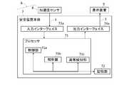
- the safety device main body 7includes a processor 71 for controlling, a storage unit 72, an input interface 73a, and an output interface 74a.
- the input interface 73aincludes a terminal for receiving information from the acceleration sensor 8 as a signal and an operation button for the operator to operate.
- the output interface 74aincludes a terminal for outputting information to the display device 9.
- the safety device main body 7is connected to the acceleration sensor 8 and the display device 9 by an electric wire 3.
- the processor 71is a CPU, includes a control unit 71a, an analysis unit 71b, and an abnormality detection unit 71c, and is connected to a storage unit 72, an input interface 73a, and an output interface 74a to exchange data.
- the control unit 71areads out from the storage unit 72 a software module that controls the analysis unit 71b and the abnormality detection unit 71c, and controls the entire safety device 6, and executes the software module.
- the analysis unit 71breads out from the storage unit 72 a software module that extracts a plurality of frequency components from the vibration measured by the acceleration sensor 8 by frequency-decomposing the vibration measured by the acceleration sensor 8 into a plurality of vibrations, and executes the software module. Is.
- the abnormality detection unit 71creads out from the storage unit 72 a software module that detects an abnormality when there is an abnormality vibration which is a vibration of a specific frequency in a plurality of vibrations frequency-decomposed by the analysis unit 71b, and executes the software module. ..
- the abnormal vibrationis a vibration having a frequency different from the vibration generated in the normal state.
- the normal statemeans a state in which no abnormality has occurred regardless of the operating state of the passenger conveyor.
- the abnormality detection unit 71crecognizes the operating state of the passenger conveyor, reads out the software module for determining the type of abnormality from the recognized operating state from the storage unit 72, and executes it. Specifically, whether or not the analysis unit 71b is operating according to whether or not there is vibration of a frequency that occurs during the operation of the passenger conveyor and does not occur during the stop while the vibration is decomposed into a plurality of frequency components. It recognizes whether it is stopped and determines the type of abnormality.
- “During operation”means that the power supply device 2 supplies electric power to the electromagnetic brake 5 and the motor according to the command of the control device 1, so that the braking by the electromagnetic brake 5 is released and the motor is driven.
- “stopped”means that power is not supplied from the power supply device 2 to the electromagnetic brake 5 and the motor according to the command of the control device 1, the speed reducer is braked by the electromagnetic brake 5, and the motor drive is stopped. be.
- the type of abnormalityis, for example, dragging or slipping.
- Draggingis an abnormality in which the lining 57a and the armature 52 or the outer disc 53 come into contact with each other even though the passenger conveyor is in operation. If the dragging state continues for a long time, the lining 57a will be worn by friction, and the speed reducer cannot be braked by the electromagnetic brake 5.
- slippingis an abnormality in which the electromagnetic brake 5 is not sufficiently braked even though the passenger conveyor is stopped, and the staircase surface 220 of the passenger conveyor moves due to an external force such as gravity.
- the storage unit 72is a storage device composed of a non-volatile memory and a volatile memory, and stores a program executed by the processor 71 and reference data used for processing of the processor 71.
- the display device 9receives and displays a signal output from the output interface 74a of the safety device main body 7 from the input interface via the electric wire 3.
- the display device 9is usually installed in a monitoring room or the like.
- FIGS. 4 and 5are flowcharts showing control of abnormality detection and abnormality determination of the safety device 6, respectively.
- control of abnormality detection of the safety device 6will be described with reference to FIG.
- the safety device main body 7is activated by pressing the power button among the operation buttons of the input interface 73a. Upon activation, the control unit 71a starts controlling the safety device 6.
- step S11the control unit 71a acquires vibration data, which is vibration information.
- the acceleration signal output by the acceleration sensor 8 and input from the input interface 73ais discretely sampled by the input interface 73a and converted into a digital signal.
- the control unit 71aacquires the converted digital signal as sampling data from the input interface 73a, and obtains a time axis waveform indicating acceleration at each time. Then, this sampling data is temporarily stored in the storage unit 72 as vibration data. Further, the sampling interval at this time is appropriately set according to the frequency to be measured. For example, it is an interval for acquiring 2048 data every 80 milliseconds.
- the control unit 71aadvances the process to step S12. It should be noted that the time axis waveform of amplitude or velocity may be calculated from the acceleration signal, and the time axis waveform may be sampled as amplitude or velocity data.
- step S12the analysis unit 71b performs frequency decomposition. Specifically, the fast Fourier transform obtains 800 frequency spectrum data for every 12.5 Hz from 12.5 Hz to 10 kHz from the time axis waveform for 80 milliseconds stored in the storage unit 72. Then, the spectrum data is temporarily stored in the storage unit 72.
- the spectral datais three-dimensional data and represents the frequency component of acceleration, which is the intensity of vibration at each frequency, every 80 milliseconds.
- the vibration intensityis evaluated by the acceleration, but the amplitude or the velocity may be calculated from the acceleration and the frequency and used as the vibration intensity.
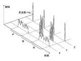
- FIG. 6shows an example of graphing the spectral data.
- This reference diagramshows the time variation of the vibration intensity at three typical frequencies.
- Xrepresents the frequency of vibration generated by the operation of the passenger conveyor.
- Yrepresents the frequency of vibration caused by the friction between the lining 57a and the armature 52.
- Zrepresents the frequency of vibration generated by the operation of the armature 52.
- P and Rare the time zones when the passenger conveyor is in operation
- Qis the time zone when the passenger conveyor is stopped. That is, this reference diagram shows that friction occurs between the lining 57a and the armature 52 in both the Q time zone when the vehicle is stopped and the R time zone when the vehicle is in operation.
- the accelerationis shown at a different scale for each frequency. The same applies to FIGS. 7 and 8.
- the abnormality detection unit 71cevaluates the vibration stored as spectral data. Specifically, the presence or absence of vibration at each frequency is evaluated from the spectral data stored in the storage unit 72 in step S12. The determination of the presence or absence of this vibration is evaluated by whether or not the acceleration exceeds the threshold value. For example, when the acceleration is equal to or higher than a certain value at a certain frequency, it is evaluated as "with vibration" at that frequency. Then, this evaluation is temporarily stored in the storage unit 72. It should be noted that this threshold value differs for each frequency or frequency band, and is experimentally determined so that the presence or absence of vibration can be easily evaluated.
- the acceleration in the state where there is no abnormality in the brake and the acceleration in the state where there is an abnormality in the brakeare measured a plurality of times, and a person determines a threshold value capable of distinguishing between the time when there is an abnormality and the time when there is no abnormality. Further, in order to distinguish whether the operating state is operating or stopped, vibration can be measured in each state and a threshold value can be determined in the same manner.
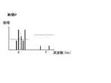
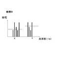
- FIG. 7 and 8are reference views showing the evaluation of vibration in step S13.
- FIG. 7is a graph showing the intensity of vibration at each frequency in a certain time zone in the time zone P of FIG.
- FIG. 8is a graph showing the intensity of vibration at each frequency in a certain time zone in the time zone R of FIG. X and Y in FIGS. 7 and 8 represent the same frequencies as X and Y in FIG.
- the broken line parallel to the frequency axis in FIGS. 7 and 8represents the threshold value. The threshold is different for each frequency, but if the acceleration exceeds this threshold, it is evaluated as having vibration.
- a vibration having a frequency of Xis evaluated as “with vibration”
- a vibration having a frequency of Yis evaluated as “without vibration”.
- both the vibration having a frequency of X and the vibration having a frequency of Yare evaluated as “with vibration”.
- step S14the abnormality detection unit 71c evaluates the vibration stored in the storage unit 72 in step S13, and lists the presence / absence of vibration at each frequency of the vibration generated in the normal state stored in the storage unit 72 in advance. To match. That is, in this list, it is stored that only the frequency at which vibration does not normally occur is “no vibration” even when the passenger conveyor is stopped or operated. That is, the frequency Y in the reference figures shown in FIGS. 6, 7, and 8 is stored as “no vibration” in the list.
- the abnormality detection unit 71cis abnormal. Is detected, and the process proceeds to step S21, which is the control of abnormality determination.
- step S21which is the control of abnormality determination.
- the abnormality detection unit 71creturns the process to step S11 again.
- step S21the abnormality detection unit 71c recognizes the operating state of the passenger conveyor from the evaluation of the vibration stored in the storage unit 72 in step S13.
- the evaluation of the vibrationis collated with the list of vibrations having frequencies stored in the storage unit 72 in advance, which are generated during the operation of the passenger conveyor and not generated during the stop. In this list, it is stored that only frequencies where vibrations occur during the operation of the passenger conveyor and no vibrations occur while the passenger conveyor is stopped are "in operation".
- the frequency stored as "in operation”is, for example, X in FIGS. 6, 7, and 8.
- the abnormality detection unit 71cadvances the process to step S22.
- the abnormality detection unit 71cadvances the process to step S23.
- step S22the abnormality detection unit 71c determines that dragging has occurred, and stores the determination result in the storage unit 72. Then, the abnormality detection unit 71c advances the process to step S24.
- step S23the abnormality detection unit 71c determines that slippage has occurred, and stores the determination result in the storage unit 72. Then, the abnormality detection unit 71c advances the process to step S24.
- step S24the control unit 71a outputs a signal for displaying the type of abnormality stored in the storage unit 72 to the display device 9 from the output interface 74a to the display device 9. After that, the control unit 71a erases the data generated by the abnormality detection and the abnormality determination from the storage unit 72, and ends the process.
- the present embodimentit is possible to detect an abnormality that has occurred in the electromagnetic brake 5 of the passenger conveyor.
- the abnormalitysince the abnormality is detected by measuring the vibration, the abnormality can be detected more quickly than the method of detecting the abnormality from the temperature change of the electromagnetic brake 5.
- dragging and slippingwhich are types of abnormalities.
- frictionoccurs between the lining 57a and the armature 52 or the outer disc 53 when the abnormality occurs in either of the abnormalities. Therefore, it is difficult to determine the type of abnormality when only the vibration of the frequency generated by friction and the temperature rise are analyzed.
- dragging and slippingcan be accurately determined.
- Both dragging and slippingare abnormalities that occur in the electromagnetic brake 5 of the passenger conveyor, but the response of the repair company who is the operator is different. Therefore, by knowing in advance whether it is dragging or slipping, the repairer can make appropriate preparations, and the efficiency of work is improved. Further, dragging is an abnormality in which the braking force of the electromagnetic brake 5 eventually drops due to wear of the lining 57a if left unattended. On the other hand, slipping is a state in which the passenger conveyor cannot be braked by the electromagnetic brake 5, and is an abnormality with higher urgency than dragging. Therefore, if dragging and slipping are determined according to the present embodiment, the urgency of the occurrence of the abnormality can be known, and an appropriate priority can be given between the response to the abnormality and other work.
- the operating state of the passenger conveyoris recognized from the vibration. Therefore, the type of abnormality can be determined without receiving the information on the operating state from the control device 1 of the passenger conveyor. Therefore, even if the control device 1 of the passenger conveyor that has already been installed is not connectable to the safety device 6, the brake safety device of the present embodiment can be installed.
- the electromagnetic brake 5 shown in FIG. 2is drawn with exaggerated size and spacing between members in order to show each configuration in an easy-to-understand manner.
- the armature 52 described laterslides between 1 mm and less.
- the field 51includes a yoke 51a, a coil 51b, and a spring 51c, and constitutes a magnetic circuit.
- the yoke 51ais a fixed iron core bolted to the speed reducer. It has a hole in the center through which the shaft 100 passes.
- the disc sidethe one with the outer disc 53 described later
- the one without the outer disc 53is referred to as the speed reducer side.
- the coil 51bis embedded in the groove on the disk side of the yoke 51a, and a magnetic field is generated by the electric power supplied from the power supply device 2 via the brake wiring 4b. Further, the spring 51c is embedded in a groove provided on the disc side of the yoke 51a, and presses the armature 52 described later toward the disc side. Although two springs 51c are provided in the present embodiment, three or more springs 51c or one spring 51c may be provided.
- the guide pin 54is embedded in the yoke 51a.
- the guide pin 54is a rod-shaped member, and the outer disc 53 is fixed to the other end opposite to one end embedded in the yoke 51a. Further, the guide pin 54 slidably supports the armature 52 in the axial direction of the shaft 100 between the yoke 51a and the outer disc 53. Specifically, the two guide pins 54 provided in parallel pass through the two holes provided in the armature 52. In the present embodiment, two guide pins 54 are provided, but three or more guide pins 54 may be provided.
- the outer disc 53is a plate-shaped member provided so as to face the disc side of the yoke 51a, and is fixed to the guide pin 54.
- the armature 52is a movable iron core provided with a hole through which the shaft 100 passes at the center. As described above, the armature 52 is slidably fixed between the yoke 51a and the outer disc 53, and is provided with two holes through which the guide pin 54 passes.
- the spline hub 56is a hub having a groove on the outer circumference, and is fixed to the shaft 100 with bolts.
- the inner disk 57is a plate-shaped member in which a groove that meshes with the groove of the spline hub 56 is provided on the inner circumference of the central hole. That is, during the operation of the passenger conveyor, the rotation of the shaft 100 of the speed reducer is transmitted to the inner disc 57 via the spline hub 56, and the inner disc 57 is rotating.
- the inner disc 57has linings 57a adhesively fixed on both sides thereof.
- the lining 57ais a friction material, and when the armature 52 is pressed toward the disc by the elastic force of the spring 51c, a frictional force is generated between the armature 52 and the outer disc 53.
- the inner disc 57brakes the shaft 100 of the speed reducer via the spline hub 56.
- the cover 55is fixed to the upper part of the outer disc 53, from the disc side of the field 51 to the reducer side of the outer disc 53, the armature 52, the guide pin 54, the inner disc 57, the lining 57a, the spline hub 56 and the shaft 100. Covering.
- the cover 55is for preventing dust from adhering to those members from above.
- the accelerometer 8is directly attached to the armature 52. Therefore, the vibration generated by the friction between the lining 57a and the armature 52 can be reliably measured. Further, by attaching to the lower part of the armature 52, the acceleration sensor 8 can be attached with the upper cover 55 attached.
- Embodiment 2is a brake safety device for a passenger conveyor that recognizes an operating state by connecting the safety device main body 7 of the safety device 6 to the control device 1 of the passenger conveyor.
- the same reference numerals as those in FIGS. 3 and 5represent the same or corresponding parts.
- the safety device main body 7is not connected to the control device 1, but in the present embodiment, it is connected by the electric wire 3.
- the configuration of the safety device main body 7will be described.
- the input interface 73b of the safety device 6further includes a terminal for inputting information from the control device 1, and the output interface 74b further includes a terminal for outputting information to the control device 1.
- the input interface 73bis an input unit, and the output interface 74b is an output unit.
- control unit 71d of the safety device 6outputs a signal for stopping the passenger conveyor from the output interface 74b when the abnormality detection unit 71e detects an abnormality, in addition to the processing of the control unit 71a of the first embodiment. It consists of software modules that perform processing.
- the abnormality detection unit 71ethat recognizes the operating state of the passenger conveyor acquires the processing for detecting the abnormality described with reference to FIG. 4 of the first embodiment and the operation information output from the control device 1. It is composed of a software module that recognizes the operating state and determines the type of abnormality.
- the input interface of the control device 1further includes a terminal for inputting information from the safety device main body 7. Further, the output interface further includes a terminal for outputting the operating state of the passenger conveyor to the safety device 6.
- the control device 1receives an electromagnetic brake from the power supply device 2 when a signal requesting the stop of the passenger conveyor is input from the safety device main body 7 to the input interface. It is provided with a software module that outputs a command to stop the power supply to the power supply device 2 and the power supply device 2. It also includes a software module that outputs a signal indicating that the passenger conveyor is in operation from the output interface while the passenger conveyor is in operation.
- step S4is added in place of step S21 of the first embodiment. Further, step S5 is added between steps S22 and S24.
- step S4the abnormality detecting unit 71e recognizes the operating state of the passenger conveyor based on the operating information output from the control device 1. Specifically, the abnormality detection unit 71e acquires a signal indicating that the vehicle is in operation. This signal is input from the control device 1 to the input interface 73b. If the acquisition of the signal indicating that the vehicle is in operation is successful, the abnormality detection unit 71e proceeds to the process in step S22. On the other hand, if the signal cannot be acquired, the abnormality detection unit 71e advances the process to step S23.
- step S5the control unit 71d outputs a signal requesting the stop of the passenger conveyor from the output interface 74b to the control device 1.
- This signalis a signal to output a command to stop the power supply from the power supply device 2 to the electromagnetic brake 5 and the motor to the control device 1.
- step S24the control unit 71d advances the process to step S24.
- the first embodimentit is possible to detect the abnormality generated in the brake of the passenger conveyor and determine the type of abnormality from the operating state of the passenger conveyor, as in the first embodiment.
- the operation informationcan be received from the control device 1 of the passenger conveyor, the operating state of the passenger conveyor can be recognized more reliably. Therefore, the type of abnormality can be determined more reliably.
- the safety device 6when the safety device 6 detects an abnormality, a signal for stopping the passenger conveyor is output to the control device 1, so that the passenger conveyor in which the abnormality has occurred can be stopped promptly. As a result, the abnormal dragging of the passenger conveyor does not continue, and the wear of the lining 57a can be minimized.
- Embodiment 3is a brake safety device for a passenger conveyor so as to determine the type of abnormality from the frequency components of vibrations generated in a normal state and vibrations having different frequencies.
- the differences from the first embodimentwill be mainly described.
- FIGS. 11 and 12the same reference numerals as those in FIGS. 3 and 5 represent the same or corresponding parts.
- the processor 71is provided with the abnormality detection unit 71c, but in the present embodiment, the abnormality detection unit 71f is provided instead.
- the abnormality detection unit 71fdetermines the type of abnormality according to the correspondence between the frequency of the abnormal vibration stored in the storage unit 72 and the type of the abnormal vibration. The software module to be determined is read from the storage unit 72 and executed.
- the storage unit 72stores a correspondence list in which the type of abnormality and the vibration generated when the abnormality occurs are associated with each other as reference data used for processing of the processor 71.
- steps S61 to S63are added instead of steps S21 to S23 of the first embodiment.
- step S14the abnormality detection unit 71c proceeded to step S21 if there was abnormal vibration.
- the processproceeds to step S61.
- the abnormality detection unit 71fdetermines the type of abnormality of the passenger conveyor from the evaluation of the vibration stored in the storage unit 72 in step S13. Specifically, the evaluation of vibration is collated with the correspondence list stored in the storage unit 72 in advance. In the following description, it is assumed that this correspondence list stores that the frequency "A" corresponds to the friction of the lining 57a such as slipping or dragging, which is a serious abnormality. Further, it is assumed that the frequency "B" corresponds to the accumulation of abrasion powder caused by the sliding of the armature 52, which is a slight abnormality. Then, it is assumed that the type of abnormality does not correspond to frequencies other than "A" and "B".
- the abnormality detection unit 71fproceeds to the process to step S62.
- the abnormality detection unit 71fadvances the process to step S63.
- the abnormality detection unit 71fadvances the process to step S24.
- step S62the abnormality detection unit 71f stores in the storage unit 72 that friction has occurred in the lining 57a. Then, the abnormality detection unit 71f advances the process to step S24.
- step S63the abnormality detection unit 71f stores in the storage unit 72 that the wear debris is accumulated. Then, the abnormality detection unit 71f advances the process to step S24.
- step S24as in the first embodiment, the control unit 71a outputs a signal for displaying the type of abnormality stored in the storage unit 72 to the display device 9 from the output interface 74a to the display device 9. At this time, if the type of abnormality is not stored, a signal for displaying on the display device 9 that an unknown abnormality has occurred is output. After that, the control unit 71a erases the data generated by the detection of the abnormality and the determination of the abnormality from the storage unit 72, and ends the process.
- the first embodimentit is possible to detect the abnormality generated in the brake of the passenger conveyor and determine the type of abnormality from the operating state of the passenger conveyor, as in the first embodiment. Further, in the present embodiment, since the type of abnormality can be determined from the frequency component of the abnormal vibration, the type of abnormality different from that of the first embodiment can be determined.
- the accelerometer 8is attached to the lower part of the armature 52 as in the first embodiment. Therefore, there is an advantage that it is easier to detect the accumulation of wear debris caused by the sliding of the armature 52 than when the acceleration sensor 8 is attached to another place of the electromagnetic brake 5.
- the electromagnetic brake 5is a disc brake, but the shape of the brake is not limited to this, and may be, for example, a drum type brake.
- the acceleration sensor 8is installed in the armature 52 in the embodiment, but it may be installed anywhere as long as it is installed in the electromagnetic brake 5. Further, although the acceleration sensor 8 was adhesively fixed to the armature 52, it may be attached in any way as long as the vibration of the electromagnetic brake 5 can be measured.
- the safety device 6is a device different from the control device 1 of the passenger conveyor, but each configuration may be provided inside the control device 1.
- the processor of the control device 1may be provided with a software module provided in the processor 71 of the safety device main body 7. good.
- the safety device main body 7is connected to the display device 9 by the electric wire 3, and in step S24, the control units 71a and 71d output a signal for displaying the type of abnormality on the display device 9.
- the display device 9is not limited to this as long as it can notify a person of an abnormality.
- itmay be a buzzer, a speaker, a lamp, or the like.
- each deviceis connected by an electric wire 3, but the connection method is naturally not limited to this. For example, it may be connected by wireless communication.
- the control units 71a and 71doutput a signal for displaying the type of abnormality, but may simply output a signal for displaying that an abnormality has occurred.
- the type of abnormalitywas determined by a method different from that of the first embodiment or the second embodiment and the third embodiment, these may be used in combination.
- the determination methods of the first embodiment and the third embodimentmay be combined. Specifically, when it is determined in step S61 of embodiment 3 that there is vibration having a frequency of "A", the process may proceed to step S21 of embodiment 1.
- the type of abnormality to be determinedis dragging or slipping, but the present invention is not limited to this.
- the abnormality detecting units 71c and 71emay recognize that the operating state of the passenger conveyor is in the process of sliding the armature 52 of the electromagnetic brake 5, and determine the accumulation of wear debris. That is, in step S21, the presence or absence of vibration generated by the sliding of the armature 52 may be determined. Further, in step S4, the abnormality detecting unit 71e may recognize that the operating state of the passenger conveyor is being switched between operating and stopped by the input from the control device 1.
- the type of abnormality to be determinedis to determine the generation of friction or the accumulation of wear debris, but the present invention is not limited to this.
- a highly accurate acceleration sensor 8 or a software module of the analysis unit 71bmay be used so that the abnormality detection unit 71f determines dragging or slipping from the frequency component of the abnormal vibration.
- the reference data used for the processing of the processor 71is stored in the storage unit 72 in advance, but it may be stored after the installation. For example, after confirming that no abnormality has occurred in another inspection device, the safety device 6 is activated, and the spectral data obtained by decomposing the vibration acquired by the control unit 71a by the analysis unit 71b is used to obtain the spectral data of the vibration generated during normal operation. It may be a list of the presence or absence of vibration at each frequency.
- the processis advanced. This may be repeated a plurality of times of abnormality detection or abnormality determination, and the process may be advanced when there is continuous vibration of a specific frequency. Further, the process may be advanced when there is a vibration of a plurality of specific frequencies. For example, the process may be advanced when there is vibration of a specific frequency at 8 or more of the 10 target frequencies.
- step S5is the control performed after step S22, but any timing may be used as long as the abnormality is detected in step S14. For example, it may be performed immediately after step S14, and if the passenger conveyor is already stopped, it may be ignored by the control device 1 of the passenger conveyor. Further, in the third embodiment, step S5 may be performed before step S24.
- the abnormality detection units 71c and 71edetermine dragging and slipping, but either one may be determined depending on the intended use.
- the abnormality detection unit 71cis described when there is a vibration with a frequency that occurs during the operation of the passenger conveyor and does not occur while the passenger conveyor is stopped during the vibration that the analysis unit 71b decomposes into a plurality of frequency components.
- the operating statewas recognized as being in operation, it may be recognized as being stopped when there is no vibration at such a frequency.
- the fast Fourier transformis used, but the method for detecting the frequency component of the vibration is not limited to this, and any method can be used as long as it can detect the vibration in a specific frequency or frequency band. You may use it.
- a resonance circuitcan be used to detect the frequency component of vibration.
- the sampling interval of the vibration data and the likeare described for the sake of explanation, but of course, these numerical values are not limited to this.
Landscapes
- Escalators And Moving Walkways (AREA)
Abstract
Description
Translated fromJapanese本開示は、乗客コンベアのブレーキ安全装置に関するものである。This disclosure relates to a brake safety device for a passenger conveyor.
特許文献1には、乗客コンベアの階段面の上面に固定され、乗客コンベアのブレーキ動作中の振動の情報を取得し、取得した振動の情報を記録する点検ロボットが開示されている。
上記の点検ロボットは記録した振動の情報に、異常振動が有るかを判断する機能を備えていない。そのため、乗客コンベアのブレーキに発生した異常を検知することができないという課題がある。The above inspection robot does not have a function to judge whether the recorded vibration information has abnormal vibration. Therefore, there is a problem that it is not possible to detect an abnormality that has occurred in the brake of the passenger conveyor.
本開示は上記の問題に鑑みてなされたものであって乗客コンベアのブレーキ安全装置において、振動の情報を取得し、取得した振動の情報からブレーキの異常を検知することができる乗客コンベアのブレーキ安全装置を提供することを目的としている。This disclosure has been made in view of the above problems, and in the brake safety device of a passenger conveyor, it is possible to acquire vibration information and detect a brake abnormality from the acquired vibration information. The purpose is to provide the device.
本開示に係る乗客コンベアのブレーキ安全装置は、乗客コンベアのブレーキに設置され、振動を計測する振動計測器と、振動計測器が計測した振動を複数の振動に周波数分解する解析部と、解析部が分解した振動に、特定の周波数の振動である異常振動があった場合に、異常を検知する異常検知部と、を備えたものである。The brake safety device for the passenger conveyor according to the present disclosure is installed on the brake of the passenger conveyor, and has a vibration measuring instrument for measuring vibration, an analysis unit for frequency-decomposing the vibration measured by the vibration measuring instrument into a plurality of vibrations, and an analysis unit. It is provided with an abnormality detecting unit for detecting an abnormality when there is an abnormal vibration which is a vibration of a specific frequency in the vibration decomposed by the above.
本開示によれば、乗客コンベアのブレーキに発生した異常を検知することができる乗客コンベアのブレーキ安全装置を提供することができる。According to the present disclosure, it is possible to provide a brake safety device for a passenger conveyor that can detect an abnormality that has occurred in the brake of the passenger conveyor.
実施の形態1.
以下に実施の形態1に係る乗客コンベアのブレーキ安全装置を図面に基づいて詳細に説明する。なお、各図面における同一の符号は同一又は相当の構成及びステップを表している。
The brake safety device of the passenger conveyor according to the first embodiment will be described in detail below with reference to the drawings. The same reference numerals in the drawings represent the same or equivalent configurations and steps.
図1はエスカレータである乗客コンベアの全体図である。乗客コンベアは全体の荷重を支えるトラス210、階段面220、階段面220を駆動する駆動装置230、及び後に説明する電磁ブレーキ5を備えている。駆動装置230は乗客コンベアの上部の機械室に設置され、動力であるモータと後に説明する減速機を備えている。なお、乗客コンベアには、勾配の無い、いわゆる動く歩道も含まれる。FIG. 1 is an overall view of a passenger conveyor which is an escalator. The passenger conveyor includes a
図2は実施の形態1における乗客コンベアのブレーキ安全装置である安全装置6を用いた乗客コンベアのブレーキシステムを示す図である。初めに、ブレーキシステム全体について図2を用いて説明する。FIG. 2 is a diagram showing a passenger conveyor brake system using the
このブレーキシステムは、制御装置1、電源装置2、電磁ブレーキ5、安全装置6、表示装置9、及び各種配線を備えている。This brake system includes a
制御装置1は乗客コンベア全体の制御を行うものであって、制御を行うプロセッサ、記憶装置、作業者が操作するための操作ボタンである入力インターフェイス、並びに電源装置2へ情報を出力する端子である出力インターフェイスを備えている。制御装置1は、電気線3により電源装置2と接続されている。The
プロセッサはCPU(Central Processing Unit)であり、乗客コンベア全体の制御を行うソフトウェアモジュールを記憶装置から読み出し、実行するものである。The processor is a CPU (Central Processing Unit), which reads out a software module that controls the entire passenger conveyor from a storage device and executes it.
電源装置2は乗客コンベアの電磁ブレーキ5及び図示しないモータに電力を供給するインバータ装置である。電源装置2は制御装置1が出力した指令に基づきブレーキ配線4b及びモータ配線4aを介して電磁ブレーキ5及びモータに電力を供給するものである。The
電磁ブレーキ5は、フィールド51、アーマチュア52、アウターディスク53、ガイドピン54、カバー55、スプラインハブ56、及びインナーディスク57を備えたディスクブレーキである。The
電磁ブレーキ5は、図示しない減速機に設置されるものである。減速機は、モータのトルクを乗客コンベアの階段面220へ伝えるものである。減速機は複数の歯車を備えており、モータの軸から得た動力を、歯車により回転速度を減じることで、乗客コンベアを駆動する動力として出力するものである。電磁ブレーキ5は、減速機を構成する歯車の一つの中心に固定された軸100を制動するものである。The
電磁ブレーキ5は、電力が供給されると磁界が発生し、アーマチュア52がフィールド51の方へ移動することで、軸100に固定されたインナーディスク57を開放することにより、減速機の制動を解除する。反対に、電力が供給されていないときには、磁界が発生しない。そのため、バネ51cの弾性力により、アーマチュア52がインナーディスク57に対して押圧され、軸100に固定されたインナーディスク57を制動することで電磁ブレーキ5は減速機の回転を減速させ、止める。電磁ブレーキ5の詳細な構成については後に説明する。In the
次に、安全装置6について説明する。安全装置6は安全装置本体7及び振動計測器である加速度センサ8を備えており、電磁ブレーキ5に発生した異常を検知するものである。加速度センサ8は振動の情報である加速度を計測し、アナログ信号として電気線3を接続する端子から出力するものである。加速度センサ8はアーマチュア52の下部に接着固定されている。また、この電気線3は、加速度センサ8の電源線を備えている。Next, the
次に安全装置本体7の詳細な構成について図3を用いて説明する。安全装置本体7は、制御を行うプロセッサ71、記憶部72、入力インターフェイス73a、及び出力インターフェイス74aを備えている。入力インターフェイス73aは、加速度センサ8からの情報を信号として受信する端子及び作業者が操作するための操作ボタンを備えている。また、出力インターフェイス74aは表示装置9に情報を出力する端子を備えている。安全装置本体7は加速度センサ8及び表示装置9と電気線3により接続されている。Next, the detailed configuration of the safety device
プロセッサ71はCPUであり、制御部71a、解析部71b、及び異常検知部71c、を備えており、記憶部72、入力インターフェイス73a、及び出力インターフェイス74aと接続されてデータのやり取りを行う。The
制御部71aは、解析部71b、及び異常検知部71cの制御、並びに安全装置6全体の制御を行うソフトウェアモジュールを記憶部72から読み出し、実行するものである。The control unit 71a reads out from the storage unit 72 a software module that controls the
解析部71bは、加速度センサ8が計測した振動を複数の振動に周波数分解することにより、加速度センサ8が計測した振動から複数の周波数成分を抽出するソフトウェアモジュールを記憶部72から読み出し、実行するものである。The
異常検知部71cは、解析部71bが周波数分解した複数の振動に、特定の周波数の振動である異常振動があった場合に異常を検知するソフトウェアモジュールを記憶部72から読み出し、実行するものである。本実施の形態において異常振動とは、正常時に発生する振動とは周波数が異なる振動である。ここで正常時とは、乗客コンベアの運転状態を問わず、異常が発生していない状態をいう。The
また、異常検知部71cは、乗客コンベアの運転状態を認識し、認識した運転状態から異常の種別を判定するソフトウェアモジュールを記憶部72から読み出し、実行するものである。具体的には、解析部71bが複数の周波数成分に分解した振動中に、乗客コンベアの運転中に発生し、停止中には発生しない周波数の振動が有るか否かに従って、運転中であるか停止中であるかを認識し、異常の種別を判定するものである。Further, the
運転中とは、制御装置1の指令により、電源装置2から電磁ブレーキ5及びモータに電力が供給されることで、電磁ブレーキ5による制動が解除され、モータが駆動している状態である。一方、停止中とは、制御装置1の指令により、電源装置2から電磁ブレーキ5及びモータに電力が供給されず、電磁ブレーキ5により減速機が制動され、モータの駆動が停止している状態である。“During operation” means that the
本実施の形態において、異常の種別とは、例えば、引き摺り又は滑りのことである。引き摺りとは乗客コンベアが運転中であるにも関わらず、ライニング57aと、アーマチュア52又はアウターディスク53とが接触する異常である。長時間、引き摺り状態が続けば摩擦によりライニング57aが摩耗し、電磁ブレーキ5により減速機を制動することができなくなる。一方、滑りとは乗客コンベアが停止中であるにも関わらず、電磁ブレーキ5の制動が十分ではなく、重力などの外力によって乗客コンベアの階段面220が動く異常である。In the present embodiment, the type of abnormality is, for example, dragging or slipping. Dragging is an abnormality in which the
記憶部72は、不揮発性メモリ及び揮発性メモリにより構成され、プロセッサ71が実行するプログラム及びプロセッサ71の処理に用いる参照データを記憶する記憶装置である。The
表示装置9は、安全装置本体7の出力インターフェイス74aから出力された信号を、電気線3を介して入力インターフェイスから受信し表示するものである。表示装置9は通常監視室などに設置されるものである。The
次に本実施の形態の動作について図4及び図5を用いて説明する。図4及び図5は、それぞれ安全装置6の異常検知及び異常判定の制御を示すフローチャートである。初めに図4を用いて、安全装置6の異常検知の制御について説明する。Next, the operation of this embodiment will be described with reference to FIGS. 4 and 5. 4 and 5 are flowcharts showing control of abnormality detection and abnormality determination of the
安全装置本体7は、入力インターフェイス73aの操作ボタンのうち、電源ボタンが押されることで起動する。起動すると制御部71aは、安全装置6の制御を開始する。The safety device
ステップS11において、制御部71aは振動の情報である振動データを取得する。具体的には、加速度センサ8が出力し、入力インターフェイス73aから入力される加速度の信号を入力インターフェイス73aに離散的にサンプリングさせ、デジタル信号に変換させる。制御部71aは、入力インターフェイス73aから変換後のデジタル信号をサンプリングデータとして取得し、各時間における加速度を示す時間軸波形を得る。そしてこのサンプリングデータを、振動データとして記憶部72に一時的に記憶する。また、このときのサンプリングの間隔は、測定対象の周波数にしたがって適宜設定される。例えば、80ミリ秒毎に2048のデータを取得する間隔である。次に、制御部71aは、ステップS12に処理を進める。なお、加速度の信号から、振幅や速度の時間軸波形を算出し、その時間軸波形を振幅や速度のデータとしてサンプリングするようにしてもよい。In step S11, the control unit 71a acquires vibration data, which is vibration information. Specifically, the acceleration signal output by the
ステップS12において、解析部71bは周波数分解を行う。具体的には、高速フーリエ変換により、記憶部72に記憶された上記の80ミリ秒分の時間軸波形から、12.5Hzから10kHzまで12.5Hz毎に800通りの周波数のスペクトルデータを得る。そして、そのスペクトルデータを記憶部72に一時的に記憶する。スペクトルデータは3次元のデータであって、80ミリ秒毎の、各周波数における振動の強度である加速度の周波数成分を表している。本実施の形態においては、振動の強度を加速度により評価しているが、加速度及び周波数から振幅又は速度を算出し、振動の強度としてもよい。In step S12, the
スペクトルデータをグラフ化した例を図6に示す。この参考図では、代表的な3つの周波数における振動の強度の時間変化を表している。Xは乗客コンベアの運転により生じる振動の周波数を表している。Yはライニング57aとアーマチュア52との間の摩擦より生じる振動の周波数を表している。Zはアーマチュア52の動作により生じる振動の周波数を表している。P及びRは乗客コンベアが運転中の時間帯、Qは停止中の時間帯である。すなわちこの参考図は、停止中であるQの時間帯と運転中であるR時間帯の両方で、ライニング57aとアーマチュア52との間の摩擦が生じていることを表している。なお、図6においては各周波数における振動の有無をわかりやすく示すために、周波数ごとに異なる縮尺で加速度を表している。図7及び図8においても同様である。Figure 6 shows an example of graphing the spectral data. This reference diagram shows the time variation of the vibration intensity at three typical frequencies. X represents the frequency of vibration generated by the operation of the passenger conveyor. Y represents the frequency of vibration caused by the friction between the
次にステップS13において異常検知部71cは、スペクトルデータとして記憶された振動を評価する。具体的には、ステップS12で記憶部72に記憶されたスペクトルデータから、各周波数における振動の有無を評価する。この振動の有無の判断は加速度が閾値を超えているか否かによって評価される。例えば、ある周波数において加速度が、ある一定の値以上であった場合に、その周波数における「振動あり」と評価する。そして、この評価を記憶部72に一時的に記憶する。なお、この閾値は周波数あるいは周波数帯毎に異なるものであり、振動の有無を評価しやすいように実験的に決定されるものである。例えば、ブレーキに異常がない状態の加速度と、ブレーキに異常がある状態の加速度とを、それぞれ複数回計測し、異常があるときと異常がないときとを区別できる閾値を人が決定する。また、運転状態が運転中であるか、停止中であるかを区別するために、同様に、それぞれの状態で振動を測定し、閾値を決定することができる。Next, in step S13, the
図7及び図8は、ステップS13における振動の評価を示す参考図である。図7は、図6のPの時間帯のうち、ある時間における各周波数の振動の強度を表したグラフである。また、図8は、図6のRの時間帯のうち、ある時間における各周波数の振動の強度を表したグラフである。図7及び図8中のX及びYは、図6におけるX及びYと同じ周波数を表している。また、図7及び図8の周波数の軸に平行な破線は閾値を表している。周波数毎に閾値は異なっているが、加速度がこの閾値を超えた場合は、振動ありと評価される。図7では、周波数がXの振動は「振動あり」であると評価され、周波数がYの振動は「振動無し」であると評価される。一方、図8では、周波数がXの振動もYの振動も「振動あり」であると評価される。7 and 8 are reference views showing the evaluation of vibration in step S13. FIG. 7 is a graph showing the intensity of vibration at each frequency in a certain time zone in the time zone P of FIG. Further, FIG. 8 is a graph showing the intensity of vibration at each frequency in a certain time zone in the time zone R of FIG. X and Y in FIGS. 7 and 8 represent the same frequencies as X and Y in FIG. Further, the broken line parallel to the frequency axis in FIGS. 7 and 8 represents the threshold value. The threshold is different for each frequency, but if the acceleration exceeds this threshold, it is evaluated as having vibration. In FIG. 7, a vibration having a frequency of X is evaluated as “with vibration”, and a vibration having a frequency of Y is evaluated as “without vibration”. On the other hand, in FIG. 8, both the vibration having a frequency of X and the vibration having a frequency of Y are evaluated as “with vibration”.
次にステップS14において異常検知部71cは、ステップS13で記憶部72に記憶された振動の評価と、あらかじめ記憶部72に記憶された正常時に発生する振動の、各周波数における振動の有無のリストとを照合する。すなわち、このリストにおいては、乗客コンベアの停止中にも運転中にも通常、振動が発生しない周波数のみが「振動無し」であると記憶されている。すなわち図6、図7、及び図8に示す参考図中のYという周波数は、リスト中では、「振動無し」であると記憶されている。照合の結果、ステップS13で「振動あり」と評価した周波数のうち、リスト中で「振動無し」であると記憶されているものがあれば、すなわち、異常振動があれば異常検知部71cは異常を検知し、異常判定の制御であるステップS21に処理を進める。一方、リスト中に「振動無し」であると記憶されているものが無ければ、異常検知部71cは処理を再びステップS11へ戻す。Next, in step S14, the
次に図5を用いて、安全装置6の異常判定の制御について説明する。図5のフローチャートの端子Aは、図4の端子Aと同じ端子である。これらの端子Aは、図4のステップS14の処理後に、図5のステップS21が実行されることを表している。ステップS21において異常検知部71cは、ステップS13で記憶部72に記憶された振動の評価から、乗客コンベアの運転状態を認識する。具体的には、振動の評価と、あらかじめ記憶部72に記憶された、乗客コンベアの運転中に発生し停止中には発生しない周波数の振動のリストとを照合する。このリストにおいては、乗客コンベアの運転中に振動が発生し、停止中には振動が発生しない周波数のみが「運転中」であると記憶されている。「運転中」であると記憶されている周波数は、具体的には、例えば図6、図7、及び図8のXである。照合の結果、ステップS13で「振動あり」と評価した周波数のうち、リスト中で「運転中」であると記憶されているものがあれば、異常検知部71cは処理をステップS22に進める。一方、「運転中」であると記憶されているものが無ければ異常検知部71cは処理をステップS23に進める。Next, the control of abnormality determination of the
ステップS22において異常検知部71cは、引き摺りが発生していると判定し、判定結果を記憶部72に記憶する。そして、異常検知部71cは処理をステップS24へ進める。一方、ステップS23においては、異常検知部71cは、滑りが発生していることを判定し、判定結果を記憶部72に記憶する。そして、異常検知部71cは処理をステップS24へ進める。In step S22, the
ステップS24において、制御部71aは記憶部72に記憶された異常の種別を表示装置9に表示させる信号を、出力インターフェイス74aから表示装置9へ出力する。その後、制御部71aは、異常検知及び異常判定により生じたデータを記憶部72から消去して、処理を終了する。In step S24, the control unit 71a outputs a signal for displaying the type of abnormality stored in the
以上、本実施の形態によれば、乗客コンベアの電磁ブレーキ5に発生した異常を検知することができる。本実施の形態では振動を計測することで異常を検知しているため、電磁ブレーキ5の温度変化から異常を検知するような手法に比べて、迅速に異常を検知することができる。As described above, according to the present embodiment, it is possible to detect an abnormality that has occurred in the
また、本実施の形態によれば、異常の種別である引き摺りと滑りを判定することできる。引き摺り及び滑りは、どちらの異常においても異常が発生したときにライニング57aとアーマチュア52又はアウターディスク53との間に摩擦が発生する。したがって、摩擦により発生する周波数の振動や温度上昇のみを解析した場合に、異常の種別を判定することは困難である。本開示においては乗客コンベアの運転状態に基づいて異常の種別を判定することにより、引き摺りと滑りを精度良く判定することができる。Further, according to the present embodiment, it is possible to determine dragging and slipping, which are types of abnormalities. In both dragging and slipping, friction occurs between the
引き摺り及び滑りは共に乗客コンベアの電磁ブレーキ5に発生する異常であるが、作業者である修理業者の対応は異なる。したがって、事前に引き摺りであるか滑りであるかを知ることにより、修理業者は適切な準備をすることができるため、作業の効率が向上する。また、引き摺りは、放置すればライニング57aの摩耗により、いずれ電磁ブレーキ5の制動力が落ちる異常である。その一方で滑りは、電磁ブレーキ5により乗客コンベアを制動できていない状態であり、引き摺りよりも緊急性の高い異常である。したがって、本実施の形態により引き摺りと滑りを判定すれば、発生した異常の緊急性を知ることができ、異常に対する対応と他の業務との間に適切な優先順位をつけることできる。Both dragging and slipping are abnormalities that occur in the
本実施の形態においては、振動から乗客コンベアの運転状態を認識している。そのため、乗客コンベアの制御装置1から、運転状態の情報を受け取ることなく異常の種別を判定することができる。したがって、既に設置している乗客コンベアの制御装置1が安全装置6と接続可能なものでない場合でも、本実施の形態のブレーキ安全装置を設置することができる。In this embodiment, the operating state of the passenger conveyor is recognized from the vibration. Therefore, the type of abnormality can be determined without receiving the information on the operating state from the
最後に本実施の形態における電磁ブレーキ5の詳細な構成について図2を用いて説明する。図2に示す電磁ブレーキ5は、各構成をわかりやすく示すために、大きさや部材同士の間隔が誇張して描かれている。例えば、後に説明するアーマチュア52は1mm以下の間で摺動するものである。Finally, the detailed configuration of the
フィールド51は、ヨーク51a、コイル51b、バネ51cを備えており、磁気回路を構成している。ヨーク51aは減速機にボルトで固定された固定鉄心である。その中心に軸100が通過する穴を有している。以下、説明のために軸100の軸方向の内、後に説明するアウターディスク53のある方をディスク側、無い方を減速機側と呼ぶ。The
コイル51bはヨーク51aのディスク側の溝に埋め込まれており、ブレーキ配線4bを介して電源装置2から供給される電力により磁界を発生させるものである。また、バネ51cはヨーク51aのディスク側に設けられた溝に埋め込まれており、後に説明するアーマチュア52をディスク側に押圧している。このバネ51cは本実施の形態において2個設けられているが3個以上でもよいし1個でもよい。The coil 51b is embedded in the groove on the disk side of the
ヨーク51aには、ガイドピン54の一端が埋め込まれている。ガイドピン54は棒状の部材であって、ヨーク51aに埋め込まれた一端の反対側の他端にアウターディスク53が固定されている。また、ガイドピン54はヨーク51aとアウターディスク53の間で、アーマチュア52を軸100の軸方向に摺動可能に支持するものである。具体的には、平行に設けられた2本のガイドピン54は、アーマチュア52に設けられた2つの穴を通過している。本実施の形態においては、ガイドピン54は2本設けられているが、3本以上設けられていてもよい。One end of the
アウターディスク53は、ヨーク51aのディスク側に対向するように設けられた板状の部材であり、ガイドピン54に固定されている。アーマチュア52は軸100が通る穴が中心に設けられた可動鉄心である。上記の通りアーマチュア52は、ヨーク51aとアウターディスク53の間で、摺動可能に固定されており、ガイドピン54が通る二つの穴が設けられている。The
スプラインハブ56は外周に溝が設けられたハブであって、軸100にボルトで固定されている。インナーディスク57は、スプラインハブ56の溝と噛み合う溝が、中心の穴の内周に設けられた板状の部材である。すなわち、乗客コンベアの運転中においては、減速機の軸100の回転が、スプラインハブ56を介してインナーディスク57まで伝わり、インナーディスク57は回転している。The
インナーディスク57はその両面にライニング57aが接着固定されている。ライニング57aは摩擦材であって、アーマチュア52がバネ51cの弾性力によりディスク側に押圧されたときに、アーマチュア52及びアウターディスク53との間で摩擦力を発生させるものである。そして、インナーディスク57は、ライニング57aに発生した摩擦力により制動された場合に、スプラインハブ56を介して、減速機の軸100を制動するものである。The
カバー55はアウターディスク53の上部に固定されており、フィールド51のディスク側から、アウターディスク53の減速機側まで、アーマチュア52、ガイドピン54、インナーディスク57、ライニング57a、スプラインハブ56及び軸100を覆っている。カバー55は、それらの部材に上部から埃が付着することを防ぐためである。The
本実施の形態では、アーマチュア52に加速度センサ8を直接取り付けている。そのため、ライニング57aとアーマチュア52との摩擦により発生する振動を確実に計測することができる。また、アーマチュア52の下部に取り付けることにより上部のカバー55を取り付けたまま、加速度センサ8を取り付けることができる。In this embodiment, the
実施の形態2.
本実施の形態は、安全装置6の安全装置本体7を乗客コンベアの制御装置1に接続することにより、運転状態を認識するようにした乗客コンベアのブレーキ安全装置である。以下、実施の形態1との相違点を中心に説明する。図9及び図10において、図3及び図5と同一の符号は同一又は相当の部分を表している。
The present embodiment is a brake safety device for a passenger conveyor that recognizes an operating state by connecting the safety device
初めに図9を用いて、本実施の形態の構成について説明する。実施の形態1において、安全装置本体7は制御装置1と接続されていなかったが、本実施の形態においては電気線3で接続されている。安全装置本体7の構成について説明する。First, the configuration of this embodiment will be described with reference to FIG. In the first embodiment, the safety device
安全装置6の入力インターフェイス73bは制御装置1からの情報を入力する端子をさらに備えており、出力インターフェイス74bは制御装置1へ情報を出力する端子をさらに備えている。入力インターフェイス73bは入力部であり、出力インターフェイス74bは出力部である。The
また、安全装置6の制御部71dは、実施の形態1の制御部71aの処理に加えて、異常検知部71eが異常を検知した場合に、乗客コンベアを停止させる信号を出力インターフェイス74bから出力させる処理を行うソフトウェアモジュールにより構成される。Further, the control unit 71d of the
本実施の形態において、乗客コンベアの運転状態を認識する異常検知部71eは、実施の形態1の図4で説明した異常を検知する処理と、制御装置1から出力される運転情報を取得することで運転状態を認識し、異常の種別を判定する処理とを行うソフトウェアモジュールにより構成される。In the present embodiment, the
次に、制御装置1の構成について説明する。本実施の形態において制御装置1の入力インターフェイスは安全装置本体7からの情報を入力する端子をさらに備えている。また、出力インターフェイスは安全装置6へ乗客コンベアの運転状態を出力する端子をさらに備えている。Next, the configuration of the
また、制御装置1は、乗客コンベア全体の制御を行うソフトウェアモジュールに加えて、入力インターフェイスに、安全装置本体7から、乗客コンベアの停止を求める信号が入力された場合に、電源装置2から電磁ブレーキ5及びモータへの電源供給を停止させる指令を、電源装置2に出力するソフトウェアモジュールを備えている。また、乗客コンベアの運転中に、乗客コンベアが運転中であることを示す信号を、出力インターフェイスから出力するソフトウェアモジュールを備えている。Further, in addition to the software module that controls the entire passenger conveyor, the
次に、本実施の形態の動作について図10を用いて説明する。本実施の形態では、実施の形態1のステップS21に代えて、ステップS4が追加されている。また、ステップS22とステップS24の間にステップS5が追加されている。Next, the operation of this embodiment will be described with reference to FIG. In the present embodiment, step S4 is added in place of step S21 of the first embodiment. Further, step S5 is added between steps S22 and S24.
本実施の形態においては、ステップS14において異常検知部71eが異常を検知した場合、処理をステップS4へ進める。ステップS4において、異常検知部71eは制御装置1から出力される運転情報に基づき乗客コンベアの運転状態を認識する。具体的には、異常検知部71eは運転中であることを示す信号を取得する。この信号は制御装置1から入力インターフェイス73bへ入力されるものである。運転中であることを示す信号の取得に成功すれば、異常検知部71eは処理をステップS22に進める。一方、その信号が取得できなかった場合、異常検知部71eは処理をステップS23に進める。In the present embodiment, when the
また、本実施の形態おいては、ステップS22の処理の後に、異常検知部71eは処理をステップS5に進める。ステップS5において、制御部71dは、乗客コンベアの停止を求める信号を出力インターフェイス74bから制御装置1に出力する。この信号は、電源装置2から電磁ブレーキ5及びモータへの電源供給を停止させる指令を、制御装置1に出力させる信号である。そして、制御部71dは処理をステップS24へ進める。Further, in the present embodiment, after the processing in step S22, the
以上、本実施の形態によれば実施の形態1と同様に、乗客コンベアのブレーキに発生した異常を検知し、乗客コンベアの運転状態から異常の種別を判定することができる。As described above, according to the first embodiment, it is possible to detect the abnormality generated in the brake of the passenger conveyor and determine the type of abnormality from the operating state of the passenger conveyor, as in the first embodiment.
また、本実施の形態においては、乗客コンベアの制御装置1から運転情報を受け取ることができるため、より確実に乗客コンベアの運転状態を認識することができる。したがって、より確実に異常の種別を判定することができる。Further, in the present embodiment, since the operation information can be received from the
さらに、本実施の形態においては、安全装置6が異常を検知した場合に、制御装置1に乗客コンベアを停止させる信号を出力するため、異常が発生した乗客コンベアを速やかに停止することができる。このことにより、乗客コンベアの異常である引き摺りが続くことが無く、ライニング57aの摩耗を最小限に抑えることができる。Further, in the present embodiment, when the
実施の形態3.
本実施の形態は、正常時に発生する振動と周波数が異なる振動の周波数成分から、異常の種別を判定するようにした乗客コンベアのブレーキ安全装置である。以下、実施の形態1との相違点を中心に説明する。図11及び図12において、図3及び図5と同一の符号は同一又は相当の部分を表している。
The present embodiment is a brake safety device for a passenger conveyor so as to determine the type of abnormality from the frequency components of vibrations generated in a normal state and vibrations having different frequencies. Hereinafter, the differences from the first embodiment will be mainly described. In FIGS. 11 and 12, the same reference numerals as those in FIGS. 3 and 5 represent the same or corresponding parts.
初めに図11を用いて、本実施の形態の構成について説明する。実施の形態1において、プロセッサ71には異常検知部71cが備えられていたが、本実施の形態ではそれに代えて、異常検知部71fが備えられている。異常検知部71fは、実施の形態1で実行していた異常を検知するソフトウェアモジュールに加えて、記憶部72に記憶された異常振動の周波数と異常振動の種別との対応にしたがって異常の種別を判定するソフトウェアモジュールを記憶部72から読み取り実行するものである。First, the configuration of this embodiment will be described with reference to FIG. In the first embodiment, the
記憶部72には、プロセッサ71の処理に用いる参照データとして、異常の種別と、その異常が発生したときに発生する振動とを対応付けた対応リストが記憶されている。The
次に、本実施の形態の動作について説明する。本実施の形態においては、実施の形態1のステップS21からステップS23に代えて、ステップS61からステップS63の処理が追加されている。Next, the operation of this embodiment will be described. In the present embodiment, the processes of steps S61 to S63 are added instead of steps S21 to S23 of the first embodiment.
実施の形態1ではステップS14において、異常検知部71cは異常振動があればステップS21に処理を進めていた。本実施の形態では、異常検知部71fは異常振動があった場合に、ステップS61へ処理を進める。In the first embodiment, in step S14, the
ステップS61において異常検知部71fは、ステップS13で記憶部72に記憶された振動の評価から、乗客コンベアの異常の種別を判定する。具体的には、振動の評価と、あらかじめ記憶部72に記憶された対応リストとを照合する。以下の説明において、この対応リストには、“A”という周波数に、重大な異常である滑りや引き摺りなどのライニング57aの摩擦が対応することが記憶されているとする。また、”B”という周波数に軽微な異常であるアーマチュア52の摺動により生じる摩耗粉の蓄積が対応することが記憶されているとする。そして、“A”及び“B”以外の周波数には異常の種別が対応していないとする。In step S61, the
照合の結果、ステップS13で「振動あり」と評価した周波数のうち、周波数が“A”である振動があれば、異常検知部71fは処理をステップS62へ進める。一方、周波数が“A”である振動が無く、周波数が“B”である振動があれば、異常検知部71fは処理をステップS63へ進める。また、周波数が“A”である振動も周波数が“B”である振動も無く、すなわち、ステップS13で「振動あり」と評価した周波数が全て“A”又は“B”でない場合は、異常検知部71fは処理をステップS24へ進める。As a result of the collation, if there is a vibration whose frequency is "A" among the frequencies evaluated as "vibration" in step S13, the
ステップS62において異常検知部71fは、ライニング57aに摩擦が発生していることを、記憶部72に記憶する。そして、異常検知部71fは処理をステップS24に進める。一方、ステップS63において異常検知部71fは、摩耗粉が蓄積していることを、記憶部72に記憶する。そして異常検知部71fは処理をステップS24に進める。In step S62, the
ステップS24においては実施の形態1と同様に、制御部71aは記憶部72に記憶された異常の種別を表示装置9に表示させる信号を、出力インターフェイス74aから表示装置9へ出力する。このとき、異常の種別が記憶されていなければ、不明な異常が発生したことを表示装置9に表示させる信号を出力する。その後、制御部71aは、異常の検知及び異常の判定により生じたデータを記憶部72から消去して、処理を終了する。In step S24, as in the first embodiment, the control unit 71a outputs a signal for displaying the type of abnormality stored in the
以上、本実施の形態によれば実施の形態1と同様に、乗客コンベアのブレーキに発生した異常を検知し、乗客コンベアの運転状態から異常の種別を判定することができる。また、本実施の形態においては、異常振動の周波数成分から異常の種別を判定することができるため、実施の形態1とは異なる異常の種別を判定できる。As described above, according to the first embodiment, it is possible to detect the abnormality generated in the brake of the passenger conveyor and determine the type of abnormality from the operating state of the passenger conveyor, as in the first embodiment. Further, in the present embodiment, since the type of abnormality can be determined from the frequency component of the abnormal vibration, the type of abnormality different from that of the first embodiment can be determined.
本実施の形態では実施の形態1と同様に、加速度センサ8をアーマチュア52の下部に取り付けている。したがって、電磁ブレーキ5の他の場所に加速度センサ8を取り付けた場合よりも、アーマチュア52の摺動により生じる摩耗粉の蓄積を検知しやすいという利点がある。In the present embodiment, the
以上、実施の形態について説明したが、本発明はこの実施の形態に限定されるものではない。以下に変形例を示す。Although the embodiment has been described above, the present invention is not limited to this embodiment. A modified example is shown below.
実施の形態において、電磁ブレーキ5はディスクブレーキであったが、ブレーキの形状はこれに限られるものではなく、例えばドラム式ブレーキなどでもよい。また、異常振動を計測しやすい場所として、実施の形態ではアーマチュア52に加速度センサ8を設置していたが、電磁ブレーキ5に設置されていればどこに設置されていてもよい。さらに、加速度センサ8はアーマチュア52に接着固定されていたが、電磁ブレーキ5の振動を計測できれば、どのように取り付けられていてもよい。In the embodiment, the
実施の形態において安全装置6は、乗客コンベアの制御装置1とは別の装置であったが、制御装置1の内部に各構成を備えるようにしてもよい。例えば、実施の形態2のように、制御装置1と情報のやり取りをするような場合において、制御装置1のプロセッサに、安全装置本体7のプロセッサ71に備えられたソフトウェアモジュールを備えるようにしてもよい。In the embodiment, the
実施の形態では、安全装置本体7は電気線3により表示装置9に接続され、ステップS24において制御部71a,71dは異常の種別を表示装置9に表示させる信号を出力するものであった。表示装置9は人に異常を通知できるものであれば当然これに限られない。例えば、ブザー、スピーカー、又はランプなどでもよい。また、実施の形態において、各装置は電気線3により接続されていたが接続方法は当然これに限られない。例えば無線通信により接続されてもよい。さらに、実施の形態では、ステップS24において、制御部71a,71dは異常の種別を表示させる信号を出力していたが、単に異常が生じたことを表示させる信号を出力してもよい。In the embodiment, the safety device
実施の形態1又は実施の形態2と、実施の形態3とは異なる方法により、異常の種別を判定するものであったが、これらは組み合わせて用いてもよい。例えば、実施の形態1と実施の形態3の判定方法を組み合わせてもよい。具体的には、実施の形態3のステップS61において周波数が“A”である振動があると判断された場合に、処理を実施の形態1のステップS21に進めるようにしてもよい。Although the type of abnormality was determined by a method different from that of the first embodiment or the second embodiment and the third embodiment, these may be used in combination. For example, the determination methods of the first embodiment and the third embodiment may be combined. Specifically, when it is determined in step S61 of
実施の形態1及び実施の形態2において、判定する異常の種別は引き摺り又は滑りであったが、これに限られない。例えば、乗客コンベアの運転状態が、電磁ブレーキ5のアーマチュア52を摺動させている途中であることを異常検知部71c,71eが認識し、摩耗粉の蓄積を判定するようにしてもよい。すなわち、ステップS21においてアーマチュア52の摺動により発生する振動の有無を判定してもよい。また、ステップS4において異常検知部71eは、制御装置1からの入力により乗客コンベアの運転状態が、運転中及び停止中の切り替え中であることを認識するようにしてもよい。In the first and second embodiments, the type of abnormality to be determined is dragging or slipping, but the present invention is not limited to this. For example, the
実施の形態3も同様に、判定する異常の種別は、摩擦の発生又は摩耗粉の蓄積を判定するものであったが、これに限られない。例えば、精度の高い加速度センサ8や解析部71bのソフトウェアモジュールを用いて、異常振動の周波数成分から、異常検知部71fが引き摺り又は滑りを判定するようにしてもよい。Similarly, in the third embodiment, the type of abnormality to be determined is to determine the generation of friction or the accumulation of wear debris, but the present invention is not limited to this. For example, a highly
実施の形態においてプロセッサ71の処理に用いる参照データは、あらかじめ記憶部72に記憶されているものであったが、設置した後に記憶するようにしてもよい。例えば、他の点検装置で異常が発生していないことを確認した後に安全装置6を起動し、制御部71aが取得した振動を解析部71bが分解したスペクトルデータを、正常時に発生する振動の、各周波数における振動の有無のリストとしてもよい。In the embodiment, the reference data used for the processing of the
実施の形態の異常検知又は異常判定の制御においては、ステップS13で「振動あり」と評価された振動に、特定の周波数の振動があれば処理を進めるものであった。これを、異常検知又は異常判定を複数回繰り返し、連続して特定の周波数の振動があった場合に処理を進めるようにしてもよい。また、複数の特定の周波数の振動があった場合に処理を進めるようにしてもよい。例えば、10の対象となる周波数のうち8以上で特定の周波数の振動があった場合に処理を進めるようにしてもよい。In the control of abnormality detection or abnormality determination of the embodiment, if the vibration evaluated as "vibration" in step S13 includes vibration of a specific frequency, the process is advanced. This may be repeated a plurality of times of abnormality detection or abnormality determination, and the process may be advanced when there is continuous vibration of a specific frequency. Further, the process may be advanced when there is a vibration of a plurality of specific frequencies. For example, the process may be advanced when there is vibration of a specific frequency at 8 or more of the 10 target frequencies.
実施の形態2においてステップS5は、ステップS22の次に行われる制御であったが、ステップS14で異常が検知された後であればどのタイミングでもよい。例えば、ステップS14の直後に行い、乗客コンベアが既に停止中であれば、乗客コンベアの制御装置1によって無視されるようにしてもよい。また、実施の形態3において、ステップS24の前にステップS5が行われるようにしてもよい。In the second embodiment, step S5 is the control performed after step S22, but any timing may be used as long as the abnormality is detected in step S14. For example, it may be performed immediately after step S14, and if the passenger conveyor is already stopped, it may be ignored by the
実施の形態1及び実施の形態2において、異常検知部71c,71eは引き摺り及び滑りを判定するものであったが、使用用途に応じてどちらか一方を判定するようにしてもよい。In the first and second embodiments, the
実施の形態1において異常検知部71cは、解析部71bが複数の周波数成分に分解した振動中に、乗客コンベアの運転中に発生し停止中には発生しない周波数の振動があった場合に、前記運転状態が運転中であると認識するものであったが、そのような周波数の振動が無い場合に停止中であると認識するものとしてもよい。In the first embodiment, the
上述の実施の形態において、高速フーリエ変換を用いたが、振動の周波数成分を検出する方法はこれに限定されず、特定の周波数又は周波数帯の振動を検出できるものであれはどのような方法を用いてもよい。例えば、共振回路を用いて振動の周波数成分を検出することもできる。また、実施の形態において説明のために、振動データのサンプリング間隔などを記載したが、当然これらの数値は、これに限定されるものではない。In the above-described embodiment, the fast Fourier transform is used, but the method for detecting the frequency component of the vibration is not limited to this, and any method can be used as long as it can detect the vibration in a specific frequency or frequency band. You may use it. For example, a resonance circuit can be used to detect the frequency component of vibration. Further, in the embodiment, the sampling interval of the vibration data and the like are described for the sake of explanation, but of course, these numerical values are not limited to this.
1 制御装置、2 電源装置、3 電気線、4a モータ配線、4b ブレーキ配線、5 電磁ブレーキ、51 フィールド、51a ヨーク、51b コイル、51c バネ、52 アーマチュア、53 アウターディスク、54 ガイドピン、55 カバー、56 スプラインハブ、57 インナーディスク、57a ライニング、6 安全装置、7 安全装置本体、71 プロセッサ、71a,71d 制御部、71b 解析部、71c,71e,71f 異常検知部、72 記憶部、73a,73b 入力インターフェイス、74a,74b 出力インターフェイス、8 加速度センサ、9 表示装置、100 軸、210 トラス、220 階段面 230 駆動装置1 control device, 2 power supply device, 3 electric wire, 4a motor wiring, 4b brake wiring, 5 electromagnetic brake, 51 field, 51a yoke, 51b coil, 51c spring, 52 armature, 53 outer disk, 54 guide pin, 55 cover, 56 spline hub, 57 inner disk, 57a lining, 6 safety device, 7 safety device body, 71 processor, 71a, 71d control unit, 71b analysis unit, 71c, 71e, 71f abnormality detection unit, 72 storage unit, 73a, 73b input Interface, 74a, 74b output interface, 8 acceleration sensor, 9 display device, 100 axes, 210 truss, 220
Claims (8)
Translated fromJapanese前記振動計測器が計測した振動を複数の振動に周波数分解する解析部と、
前記解析部が分解した振動に、特定の周波数の振動である異常振動があった場合に、異常を検知する異常検知部と、
を備えた乗客コンベアのブレーキ安全装置。A vibration measuring instrument installed on the brakes of a passenger conveyor to measure vibration,
An analysis unit that frequency-decomposes the vibration measured by the vibration measuring instrument into multiple vibrations,
An abnormality detection unit that detects an abnormality when the vibration decomposed by the analysis unit includes an abnormal vibration that is a vibration of a specific frequency.
Brake safety device for passenger conveyors equipped with.
ことを特徴とする請求項1に記載の乗客コンベアのブレーキ安全装置。The abnormality detecting unit determines the type of the abnormality from the operating state of the passenger conveyor.
The brake safety device for a passenger conveyor according to claim 1.
ことを特徴とする請求項2に記載の乗客コンベアのブレーキ安全装置。The type of abnormality determined by the abnormality detecting unit includes at least one of dragging determined when the operating state is in operation and slipping determined when the operating state is stopped. The brake safety device for a passenger conveyor according to claim 2.
ことを特徴とする請求項2又は3に記載の乗客コンベアのブレーキ安全装置。The abnormality detecting unit recognizes the operating state according to the presence or absence of vibration of a frequency that occurs during the operation of the passenger conveyor and does not occur during the operation of the passenger conveyor during the vibration disassembled by the analysis unit. The brake safety device for the passenger conveyor according to item 2 or 3.
前記異常検知部は前記入力部に入力された前記運転状態の情報に基づき、前記異常の種別を判定する
ことを特徴とする請求項2又は3に記載の乗客コンベアのブレーキ安全装置。It is provided with an input unit for receiving information on the operating state output by the control device of the passenger conveyor.
The brake safety device for a passenger conveyor according to claim 2 or 3, wherein the abnormality detecting unit determines the type of the abnormality based on the information of the operating state input to the input unit.
前記異常検知部は、前記記憶部に記憶された前記異常振動の周波数と前記異常の種別との対応に従って、前記異常の種別を判定する
ことを特徴とする請求項1から5のいずれか一つに記載の乗客コンベアのブレーキ安全装置。A storage unit that stores the type of abnormality corresponding to the frequency of the abnormal vibration is provided, and the abnormality detecting unit has the abnormality according to the correspondence between the frequency of the abnormal vibration stored in the storage unit and the type of the abnormality. The brake safety device for a passenger conveyor according to any one of claims 1 to 5, wherein the type of the passenger conveyor is determined.
ことを特徴とする請求項1から6のいずれか一つに記載の乗客コンベアのブレーキ安全装置。The brake safety device for a passenger conveyor according to any one of claims 1 to 6, wherein the vibration measuring instrument is attached to the armature of the brake.
を備えたことを特徴とする請求項1から7のいずれか一つに記載の乗客コンベアのブレーキ安全装置。A control unit that outputs a signal for stopping the passenger conveyor to the control device of the passenger conveyor when the abnormality detection unit detects the abnormality.
The brake safety device for a passenger conveyor according to any one of claims 1 to 7, wherein the brake safety device is provided.
Priority Applications (2)
| Application Number | Priority Date | Filing Date | Title |
|---|---|---|---|
| PCT/JP2020/019733WO2021234807A1 (en) | 2020-05-19 | 2020-05-19 | Passenger conveyor brake safety device |
| JP2021516715AJPWO2021234807A1 (en) | 2020-05-19 | 2020-05-19 |
Applications Claiming Priority (1)
| Application Number | Priority Date | Filing Date | Title |
|---|---|---|---|
| PCT/JP2020/019733WO2021234807A1 (en) | 2020-05-19 | 2020-05-19 | Passenger conveyor brake safety device |
Publications (1)
| Publication Number | Publication Date |
|---|---|
| WO2021234807A1true WO2021234807A1 (en) | 2021-11-25 |
Family
ID=78708426
Family Applications (1)
| Application Number | Title | Priority Date | Filing Date |
|---|---|---|---|
| PCT/JP2020/019733CeasedWO2021234807A1 (en) | 2020-05-19 | 2020-05-19 | Passenger conveyor brake safety device |
Country Status (2)
| Country | Link |
|---|---|
| JP (1) | JPWO2021234807A1 (en) |
| WO (1) | WO2021234807A1 (en) |
Citations (5)
| Publication number | Priority date | Publication date | Assignee | Title |
|---|---|---|---|---|
| JP2005247468A (en)* | 2004-03-02 | 2005-09-15 | Mitsubishi Electric Corp | Elevator equipment |
| JP2008222394A (en)* | 2007-03-14 | 2008-09-25 | Hitachi Ltd | Elevator equipment |
| JP2010064816A (en)* | 2008-09-09 | 2010-03-25 | Mitsubishi Electric Corp | Passenger conveyer |
| JP2012021622A (en)* | 2010-07-16 | 2012-02-02 | Mitsubishi Electric Corp | Braking apparatus of driving machine |
| JP2017081687A (en)* | 2015-10-27 | 2017-05-18 | 株式会社日立製作所 | Elevator device and operation control method for the same |
- 2020
- 2020-05-19JPJP2021516715Apatent/JPWO2021234807A1/jaactivePending
- 2020-05-19WOPCT/JP2020/019733patent/WO2021234807A1/ennot_activeCeased
Patent Citations (5)
| Publication number | Priority date | Publication date | Assignee | Title |
|---|---|---|---|---|
| JP2005247468A (en)* | 2004-03-02 | 2005-09-15 | Mitsubishi Electric Corp | Elevator equipment |
| JP2008222394A (en)* | 2007-03-14 | 2008-09-25 | Hitachi Ltd | Elevator equipment |
| JP2010064816A (en)* | 2008-09-09 | 2010-03-25 | Mitsubishi Electric Corp | Passenger conveyer |
| JP2012021622A (en)* | 2010-07-16 | 2012-02-02 | Mitsubishi Electric Corp | Braking apparatus of driving machine |
| JP2017081687A (en)* | 2015-10-27 | 2017-05-18 | 株式会社日立製作所 | Elevator device and operation control method for the same |
Also Published As
| Publication number | Publication date |
|---|---|
| JPWO2021234807A1 (en) | 2021-11-25 |
Similar Documents
| Publication | Publication Date | Title |
|---|---|---|
| JP6077592B2 (en) | Motor control system and brake abnormality detection method having function of detecting brake abnormality | |
| JP5247690B2 (en) | Elevator safety device | |
| CN102000985B (en) | For the emergency braking system of toolroom machine | |
| US9233818B2 (en) | Monitoring of brake | |
| JP4589424B2 (en) | Inspection system and inspection method for elevator safety device | |
| US11242220B2 (en) | Safety braking systems for elevators | |
| JPH0367880A (en) | Method of detecting physical parameter of elevator | |
| CN101397113A (en) | Diagnosis device of chain slack for passenger conveying equipment and diagnosis method | |
| JP2019182661A (en) | Elevator brake | |
| CN104555643A (en) | Stall condition detection | |
| JP5906651B2 (en) | Brake test method for vehicle and brake test system for vehicle | |
| WO2021234807A1 (en) | Passenger conveyor brake safety device | |
| KR101280393B1 (en) | An inspection system for abs bearing of smart sensor-type | |
| JP7399125B2 (en) | Electromagnetic brake motion compensation device | |
| CN102951571A (en) | Control device method of winch for elevator equipment and modified method of control device | |
| EP3613692B1 (en) | Elevator monitoring using vibration sensors near the elevator machine | |
| JP2011214683A (en) | Brake shoe and elevator brake device | |
| JP2011148578A (en) | Electromagnetic brake inspection device of elevator | |
| EP2407410A1 (en) | Elevator device | |
| JP5026078B2 (en) | Elevator equipment | |
| JP3639080B2 (en) | Elevator brake characteristics evaluation system | |
| JP4974745B2 (en) | Magnet brake diagnostic device for passenger conveyor | |
| JP6314074B2 (en) | Brake device, hoisting machine and elevator device | |
| JP2010058913A (en) | Brake device for elevator | |
| EP3945059B1 (en) | Beam climber friction monitoring system |
Legal Events
| Date | Code | Title | Description |
|---|---|---|---|
| ENP | Entry into the national phase | Ref document number:2021516715 Country of ref document:JP Kind code of ref document:A | |
| 121 | Ep: the epo has been informed by wipo that ep was designated in this application | Ref document number:20937131 Country of ref document:EP Kind code of ref document:A1 | |
| NENP | Non-entry into the national phase | Ref country code:DE | |
| 122 | Ep: pct application non-entry in european phase | Ref document number:20937131 Country of ref document:EP Kind code of ref document:A1 |