WO2021225082A1 - Information processing device, information processing method, housing for head-mounted display, and head-mounted display system - Google Patents
Information processing device, information processing method, housing for head-mounted display, and head-mounted display systemDownload PDFInfo
- Publication number
- WO2021225082A1 WO2021225082A1PCT/JP2021/016461JP2021016461WWO2021225082A1WO 2021225082 A1WO2021225082 A1WO 2021225082A1JP 2021016461 WJP2021016461 WJP 2021016461WWO 2021225082 A1WO2021225082 A1WO 2021225082A1
- Authority
- WO
- WIPO (PCT)
- Prior art keywords
- indicator
- information processing
- unit
- processing device
- housing
- Prior art date
- Legal status (The legal status is an assumption and is not a legal conclusion. Google has not performed a legal analysis and makes no representation as to the accuracy of the status listed.)
- Ceased
Links
Images


Classifications
- G—PHYSICS
- G02—OPTICS
- G02B—OPTICAL ELEMENTS, SYSTEMS OR APPARATUS
- G02B27/00—Optical systems or apparatus not provided for by any of the groups G02B1/00 - G02B26/00, G02B30/00
- G02B27/01—Head-up displays
- G02B27/017—Head mounted
- G02B27/0172—Head mounted characterised by optical features
- G—PHYSICS
- G09—EDUCATION; CRYPTOGRAPHY; DISPLAY; ADVERTISING; SEALS
- G09G—ARRANGEMENTS OR CIRCUITS FOR CONTROL OF INDICATING DEVICES USING STATIC MEANS TO PRESENT VARIABLE INFORMATION
- G09G5/00—Control arrangements or circuits for visual indicators common to cathode-ray tube indicators and other visual indicators
- G09G5/36—Control arrangements or circuits for visual indicators common to cathode-ray tube indicators and other visual indicators characterised by the display of a graphic pattern, e.g. using an all-points-addressable [APA] memory
- G09G5/38—Control arrangements or circuits for visual indicators common to cathode-ray tube indicators and other visual indicators characterised by the display of a graphic pattern, e.g. using an all-points-addressable [APA] memory with means for controlling the display position
- G—PHYSICS
- G02—OPTICS
- G02B—OPTICAL ELEMENTS, SYSTEMS OR APPARATUS
- G02B27/00—Optical systems or apparatus not provided for by any of the groups G02B1/00 - G02B26/00, G02B30/00
- G02B27/01—Head-up displays
- G02B27/017—Head mounted
- G—PHYSICS
- G02—OPTICS
- G02B—OPTICAL ELEMENTS, SYSTEMS OR APPARATUS
- G02B27/00—Optical systems or apparatus not provided for by any of the groups G02B1/00 - G02B26/00, G02B30/00
- G02B27/01—Head-up displays
- G02B27/0179—Display position adjusting means not related to the information to be displayed
- H—ELECTRICITY
- H04—ELECTRIC COMMUNICATION TECHNIQUE
- H04N—PICTORIAL COMMUNICATION, e.g. TELEVISION
- H04N13/00—Stereoscopic video systems; Multi-view video systems; Details thereof
- H04N13/30—Image reproducers
- H04N13/332—Displays for viewing with the aid of special glasses or head-mounted displays [HMD]
- H04N13/344—Displays for viewing with the aid of special glasses or head-mounted displays [HMD] with head-mounted left-right displays
- H—ELECTRICITY
- H04—ELECTRIC COMMUNICATION TECHNIQUE
- H04N—PICTORIAL COMMUNICATION, e.g. TELEVISION
- H04N13/00—Stereoscopic video systems; Multi-view video systems; Details thereof
- H04N13/30—Image reproducers
- H04N13/398—Synchronisation thereof; Control thereof
- H—ELECTRICITY
- H04—ELECTRIC COMMUNICATION TECHNIQUE
- H04N—PICTORIAL COMMUNICATION, e.g. TELEVISION
- H04N23/00—Cameras or camera modules comprising electronic image sensors; Control thereof
- H04N23/20—Cameras or camera modules comprising electronic image sensors; Control thereof for generating image signals from infrared radiation only
- H—ELECTRICITY
- H04—ELECTRIC COMMUNICATION TECHNIQUE
- H04N—PICTORIAL COMMUNICATION, e.g. TELEVISION
- H04N23/00—Cameras or camera modules comprising electronic image sensors; Control thereof
- H04N23/90—Arrangement of cameras or camera modules, e.g. multiple cameras in TV studios or sports stadiums
- G—PHYSICS
- G02—OPTICS
- G02B—OPTICAL ELEMENTS, SYSTEMS OR APPARATUS
- G02B27/00—Optical systems or apparatus not provided for by any of the groups G02B1/00 - G02B26/00, G02B30/00
- G02B27/01—Head-up displays
- G02B27/0101—Head-up displays characterised by optical features
- G02B2027/0132—Head-up displays characterised by optical features comprising binocular systems
- G02B2027/0136—Head-up displays characterised by optical features comprising binocular systems with a single image source for both eyes
- G—PHYSICS
- G02—OPTICS
- G02B—OPTICAL ELEMENTS, SYSTEMS OR APPARATUS
- G02B27/00—Optical systems or apparatus not provided for by any of the groups G02B1/00 - G02B26/00, G02B30/00
- G02B27/01—Head-up displays
- G02B27/0101—Head-up displays characterised by optical features
- G02B2027/0138—Head-up displays characterised by optical features comprising image capture systems, e.g. camera
- G—PHYSICS
- G02—OPTICS
- G02B—OPTICAL ELEMENTS, SYSTEMS OR APPARATUS
- G02B27/00—Optical systems or apparatus not provided for by any of the groups G02B1/00 - G02B26/00, G02B30/00
- G02B27/01—Head-up displays
- G02B27/0101—Head-up displays characterised by optical features
- G02B2027/014—Head-up displays characterised by optical features comprising information/image processing systems
- G—PHYSICS
- G09—EDUCATION; CRYPTOGRAPHY; DISPLAY; ADVERTISING; SEALS
- G09F—DISPLAYING; ADVERTISING; SIGNS; LABELS OR NAME-PLATES; SEALS
- G09F19/00—Advertising or display means not otherwise provided for
- G09F19/12—Advertising or display means not otherwise provided for using special optical effects
- G09F19/125—Stereoscopic displays; 3D displays
- G—PHYSICS
- G09—EDUCATION; CRYPTOGRAPHY; DISPLAY; ADVERTISING; SEALS
- G09G—ARRANGEMENTS OR CIRCUITS FOR CONTROL OF INDICATING DEVICES USING STATIC MEANS TO PRESENT VARIABLE INFORMATION
- G09G2340/00—Aspects of display data processing
- G09G2340/04—Changes in size, position or resolution of an image
- G09G2340/0464—Positioning
- G09G2340/0478—Horizontal positioning
Definitions
- This disclosurerelates to an information processing device, an information processing method, a housing for a head-mounted display, and a head-mounted display system.
- the present disclosurehas been made in view of the above, and an object of the present disclosure is to provide an information processing device, a head-mounted display housing, and an information processing method capable of providing a virtual reality experience suitable for an individual user. And.
- an information processing devicethat can be used as a head-mounted display by being detachably held in a housing, and is a display unit that displays an image.
- Information processingincluding a detection unit that detects an indicator provided in the housing and a control unit that controls an image displayed on the display unit based on the information indicated by the indicator detected by the detection unit. The device, provided.
- the information processing device 100 in the present embodimentincludes a CPU (Central Processing Unit) 102, a GPU (Graphics Processing Unit) 104, a RAM (Random Access Memory) 106, a VRAM (Video RAM) 108, a storage 110, a display 112, and a visible light camera. It is composed of 114, an infrared camera 116, a microphone 118, a touch sensor 120, a visible light projector 122, an infrared projector 124, and the like, and is mainly connected via a bus 126.
- a CPUCentral Processing Unit
- GPUGraphics Processing Unit
- RAMRandom Access Memory
- VRAMVideo RAM
- the CPU 102is an arithmetic unit that performs various arithmetic operations.
- the CPU 102executes, for example, after copying the program 3042 stored in the storage 110 to the RAM 106.
- the CPU 102may be a part of an integrated circuit constituting a SoC (System on a Chip) provided on the control board.
- SoCSystem on a Chip
- the CPU 102also controls the image displayed on the display 112. For example, a command for displaying the image recorded in the VRAM 108 on the display 112 is issued to the GPU 104 to be displayed on the display 112.
- the CPU 102also controls various devices such as GPU 104, RAM 106, VRAM 108, storage 110, display 112, visible light camera 114, infrared camera 116, microphone 118, touch sensor 120, visible light floodlight 122, and infrared floodlight 124. And process the input from various devices.
- various devicessuch as GPU 104, RAM 106, VRAM 108, storage 110, display 112, visible light camera 114, infrared camera 116, microphone 118, touch sensor 120, visible light floodlight 122, and infrared floodlight 124. And process the input from various devices.
- the GPU 104is an arithmetic unit whose main purpose is to execute an arithmetic for image processing, and executes an arithmetic in response to a command from the CPU 102 as described above.
- the GPU 104may also be a part of an integrated circuit constituting a SoC (System on a Chip) provided on the control board.
- SoCSystem on a Chip
- the RAM 106is a main storage device used as a work area when the CPU 102 executes the program 3042.
- the RAM 106like the CPU 102 and the GPU 104, may also be a part of an integrated circuit constituting the SoC provided on the control board.
- the VRAM 108is a main storage device mainly used as a work area when the above-mentioned GPU 104 performs calculations for image processing.
- the VRAM 108may be a UMA (Unified Memory Architecture) having a configuration shared with the above-mentioned RAM 106.
- the storage 110is composed of an auxiliary storage device such as an HDD (Hard Disk Drive) or a flash memory, for example.
- an HDDHard Disk Drive
- flash memoryfor example.
- the display 112 in the present embodimentvisually presents the image generated by the GPU 104 or the like to the user, and is realized by, for example, a liquid crystal display, an organic EL (Electro-Luminescence) display, or the like.
- the visible light camera 114 in this embodimentincludes at least a lens 206, an image sensor (CMOS, CCD, etc.) and a color filter.
- the visible light camera 114may be arranged on either the front surface or the back surface of the information processing device 100, or may be arranged on either the front surface or the back surface. Further, visible light cameras 114 having a plurality of focal lengths may be provided side by side.
- the infrared camera 116 in this embodimentincludes at least a lens 206, an image sensor (CMOS, CCD, etc.) and an infrared filter. Like the visible light camera 114, the infrared camera 116 may be arranged on either the front surface or the back surface of the information processing device 100, or may be arranged on either the front surface or the back surface. Further, an infrared camera 116 having a plurality of focal lengths may be provided, or an infrared camera 114 may be provided.
- the microphone 118 in this embodimentis a device that converts sound into an electric signal.
- the microphone 118converts the user's utterance into an electric signal in order to enable the users to talk to each other, and the converted electric signal is the other party of the call. Will be sent to.
- the touch sensor 120 in this embodimenthas a function of detecting contact by the user.
- the touch sensor 120may be, for example, a capacitance type or pressure sensitive type touch sensor 120.
- the touch sensor 120can detect a contact action such as touching, stroking, hitting, and pushing by the user, and can perform an operation according to the contact action.
- the touch sensor 120may be provided so as to be integrated with the display 112 of the information processing device 100.
- Examples of the visible light floodlight device 122 in the present embodimentinclude photographic flashes such as xenon tube flashes and LED flashes.
- photographic flashessuch as xenon tube flashes and LED flashes.
- Examples of the infrared projector 124 in the present embodimentinclude an infrared light, an infrared dot projector, and the like for taking a picture with an infrared camera. Similar to the visible light projector 122, the infrared projector 124 also causes the infrared projector 124 to emit light to emit infrared rays even when the amount of light is insufficient due to a dark place when an object is imaged by the infrared camera 116. The amount of light can be obtained, which enables imaging.
- the information processing device 100 illustrated in this descriptionis merely an example, and various information processing devices including a display and a camera, such as a smartphone, a tablet terminal, and a portable game machine, can be used.
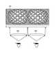
- Head-mounted display housing 2A and 2Bshow an example of the head-mounted display housing 200 according to the present embodiment, and show a conceptual diagram of an external view and an internal view, respectively.
- the head-mounted display housing (hereinafter, simply referred to as a housing) 200 in the present embodimentincludes a holding portion 202, an indicator 204, a lens 206, an adjusting mechanism 208, an auxiliary optical system 210, a first moving mechanism 212, and a second moving mechanism. It is composed of 214, etc.
- the holding unit 202holds the user's information processing device 100.
- the holding unit 202also holds the information processing device 100 in order to prevent light from leaking into the housing 200 through a gap formed between the housing 200 and the information processing device 100.
- a cover(not shown) may be further held so as to cover the information processing apparatus 100.
- the indicator 204indicates the positional relationship between the user's eyes. More specifically, the indicator 204 may indicate the user's interpupillary distance. The indicator 204 is adjusted by the adjustment mechanism 208 described later. The indicator 204 is provided at a position that can be detected by various sensors (visible light camera 114, infrared camera 116, microphone 118, touch sensor 120, etc.) of the information processing apparatus 100.
- the positional relationship between the eyes of the user indicated by the indicator 204changes, for example, when the user adjusts the indicator 204.
- indicator 204changes at least one of color, shape, pattern, position, rotation angle, length or size that is at least part of the appearance, based on user adjustments. At least a part of the appearance of the indicator 204 can be detected by various sensors of the information processing apparatus 100.
- the indicator 204is not limited to the configuration as described above, which indicates the positional relationship between the user's eyes in appearance.
- the indicator 204may be configured to come into contact with the touch sensor 120 of the information processing device 100 attached to the housing 200.
- the position on the touch sensor 120 with which the indicator 204 comes into contactmay change based on the adjustment of the indicator 204 by the user.
- the indicator 204may be a member that generates a sound according to the positional relationship between the user's eyes. In this case, the indicator 204 may change at least one of the frequency, volume, and type of sound generated, based on user adjustments.
- the lens 206is a lens that enables stereoscopic viewing of an image displayed on the display 112 of the information processing device 100 when the information processing device 100 is held, and is a lens for the right eye 206R and a left eye. Includes two lenses for the 206L lens.
- the right eye lens 206R and the right eye lens 206Rare arranged in the housing 200 so that the right eye lens 206R is arranged in front of the user's right eye and the left eye lens 206L is arranged in front of the left eye.
- the left eye lens 206Lis arranged.
- the adjustment mechanism 208adjusts the distance between the right eye lens 206R and the left eye lens 206L described above, and also adjusts the indicator 204.
- the indicator 204may indicate information indicating the positional relationship between the user's eyes.
- the information indicating the positional relationship between the user's eyesmay be information indicating the distance between the optical centers of the left and right lenses 206 adjusted by the user.
- the length of the indicator 204may change so as to indicate the distance between the left and right lenses 206 when the indicator 204 is adjusted by the adjustment mechanism 208. Further, the indicator 204 may change the rotation angle so as to indicate the distance between the left and right lenses 206. Further, the indicator 204 may make a sound at a frequency indicating the distance between the left and right lenses 206. Further, the indicator 204 may change the contact position on the touch sensor 120 so as to indicate the distance between the left and right lenses 206.
- the distance between the camera and the indicator 204is shorter than the shortest shooting distance of the camera.
- the auxiliary optical system 210may be a lens, a prism, or a mirror.
- the auxiliary optical system 210is a lens, the above-mentioned camera and the lens of the auxiliary optical system 210 may be integrated to enable focused imaging by shortening the shortest shooting distance.
- the auxiliary optical system 210is a prism or a mirror, the optical path length from the camera to the indicator 204 may be extended to enable focused imaging.
- the first moving mechanism 212moves the position of the indicator 204.
- the first moving mechanism 212may move the indicator 204 to a position where it can be imaged from the camera provided in the information processing device 100 held in the housing 200 by the operation of the user. That is, even if the information processing device 100 of different types and the cameras are arranged in different places is mounted on the housing 200, the indicator 204 can be moved according to the position of the camera. , Various types of information processing devices 100 may be mounted on the housing 200.
- the second moving mechanism 214moves the position of the auxiliary optical system 210.
- the second moving mechanism 214may move the auxiliary optical system 210 so that the indicator 204 can be imaged from the camera provided in the information processing device 100 held in the housing 200 by the operation of the user. That is, even if the information processing device 100, which is a different type of information processing device 100 and whose cameras are arranged in different places, is mounted on the housing 200, the auxiliary optical system 210 is adjusted to the positions of the camera and the indicator 204. Since it is movable, various types of information processing devices 100 may be attached to the housing 200 so that they can be used.
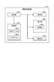
- FIG. 3shows an example of the functional configuration of the information processing apparatus 100 according to the present embodiment.
- the function of the information processing device 100 in this embodimentis composed of a control unit 302, a storage unit 304, a display unit 306, a detection unit 308, a light emitting unit 310, and the like.
- control unit 302is realized by executing the program 3042 stored in the storage unit 304 by the CPU 102 described above.
- the program 3042 stored in the storage unit 304is copied to the main storage device such as the above-mentioned RAM 106, which is a work area, and then executed by the CPU 102.
- the control unit 302also controls the image displayed on the display unit 306. For example, a command for displaying the image recorded in the VRAM 108 on the display unit 306 is issued to the GPU 104 and displayed on the display unit 306.
- the control unit 302also gives a detection command to the detection unit 308. For example, the control unit 302 instructs the detection unit 308 to detect the indicator 204 at a given timing during the execution of the program 3042, and stores the detection result in the main storage device.
- the control unit 302also controls the reading of the information data indicated by the indicator 204 detected by the detection unit 308 and the analysis of the reading result, and controls the image displayed on the display unit 306 based on the analysis. For example, the control unit 302 detects the indicator 204 by the detection unit 308, analyzes the detection result, extracts the information indicated by the indicator 204, and adjusts the image displayed on the display unit 306 based on the extracted information. do.
- the control unit 302also determines whether or not a predetermined condition is satisfied, and if the condition is satisfied, commands the detection unit 308 to detect the light emitting unit 310 while controlling the light emission. For example, when the detection unit 308 includes the image pickup unit 3080 and the image pickup unit 3080 images the indicator 204, it is determined that a predetermined condition is satisfied, and the light emission of the light emitting unit 310 is controlled.
- the storage unit 304is composed of a storage 110 which is an auxiliary storage device such as an HDD (Hard Disk Drive) or a flash memory, for example.
- the storage unitstores a program 3042 that controls the information processing apparatus 100, and a correspondence table 3040 that associates the information indicated by the indicator 204 with the control of the image displayed on the display unit 306. Specifically, it stores a correspondence table 3040 that associates the interpupillary distance indicated by the indicator 204 with the distance between the left-eye image and the right-eye image displayed on the display unit 306.
- the program 3042 stored in the storage unitis copied to a work area such as the RAM 106 and then executed by the CPU 102 or the like when the user gives an instruction to start the program execution as described above. Further, the correspondence table 3040 stored in the storage unit is used to control the image displayed on the display unit 306 together with the state of the indicator 204 detected by the detection unit 308.
- the display unit 306 in the present embodimentvisually presents the image or the like generated by the control unit 302 to the user, and is realized by the display 112 of the information processing device 100.
- the display unit 306may display the moving image information or the like stored in the storage unit under the control of the control unit 302. That is, the control unit 302 reads the moving image file stored in the storage unit as a file stream, sequentially transfers the moving image file to the VRAM 108, and is a moving image transferred onto the VRAM 108, which is the time axis of the original moving image file. A command for displaying a moving image of a part of the direction on the display unit 306 may be issued and displayed on the display unit 306.
- the display unit 306receives and controls moving image information generated by an external server (not shown) different from the information terminal device and the housing 200 by using a communication unit (not shown) provided in the information terminal device. It may be displayed by the control by the unit 302.
- the detection unit 308 in this embodimentdetects the indicator 204 of the housing 200.
- the detection unit 308may be a sensory sensor for sound, touch, sight, and the like. Examples include a microphone 118 as a sound sensor, a touch sensor 120 as a tactile sensor, and a visible light camera 114 and an infrared camera 116 as visual sensors.
- the imaging unit 3080 in this embodimentis a camera such as a visible light camera 114 or an infrared camera 116 provided in the detection unit 308 described above.
- the image pickup unit 3080includes at least a lens, an image sensor (CMOS, CCD, etc.) and a filter (color filter, infrared filter, etc.).
- the image pickup unit 3080may be arranged on either the front surface or the back surface of the information processing apparatus 100, or may be further provided with a visible light camera 114 and an infrared camera.
- the light emitting unit 310 in the present embodimentis realized by the visible light projecting device 122 and the infrared light projecting device 124 of the information processing device 100 as described above.
- the image emitting unit 310may be made to emit light to obtain the amount of light, thereby enabling the imaging.
- the light emitting unit 310may be a display unit 306 instead of the above flash or the like. That is, when the display unit 306 is composed of a light emitting display 112 such as a liquid crystal display or an organic EL (Electro-Luminescence) display, the amount of light of the display 112 can be reduced by controlling the content of the image displayed by the display unit 306. Can be controlled. Therefore, when an object is imaged by the imaging unit 3080, even if the amount of light is insufficient in a dark place, the image can be taken by obtaining the amount of light from the display 112.
- a light emitting display 112such as a liquid crystal display or an organic EL (Electro-Luminescence) display
- the userfirst activates the program 3042 of the information processing device 100 owned by the user.
- This program 3042is a program 3042 for using the information processing device 100 as a head-mounted display.
- an image for the right eye and an image for the left eyewhich are images for binocular stereoscopic vision, are displayed as shown in FIG. Only when the image is combined with the housing 200 as described later, the user can experience a stereoscopic image without failure.
- the userfits the information processing device 100 in the state where the program 3042 is started into the housing 200 so as to be held by the holding unit 202 of the housing 200.
- the display unit 306106 of the information processing device 100is fitted so as to face the inside of the housing 200.
- the userattaches the housing 200 into which the information processing device 100 is fitted to his / her head by using the headband provided in the housing 200.
- two lenses 206are arranged at positions facing the display unit 306 of the information processing device 100 in a state where the information processing device 100 is held by the holding unit 202.
- the two lenses 206are a right eye lens 206R and a left eye lens 206L, respectively.
- the image for the right eye of the display unit 306106 of the information processing device 100can be viewed by the user's right eye through the right eye lens 206R arranged in the housing 200. The same applies to the image for the left eye.
- the userIf the user's interpupillary distance and the positions of the right eye lens 206R and the left eye lens 206L described above do not match, a suitable virtual reality experience cannot be obtained.
- the useroperates an adjustment mechanism partially exposed to the outside of the housing 200 in order to obtain a suitable virtual reality experience, and the right eye lens 206R and the left eye lens 206L of the housing 200 are operated. Adjust the distance between them to match the distance between the optical centers of the lens 206 to the user's own interpupillary distance.
- the adjustment mechanismfurther adjusts at least one of the color, shape, pattern, position, rotation angle, length or size of the indicator 204 arranged inside.
- the information processing device 100 held in the housing 200detects the indicator 204 adjusted by the adjustment mechanism 208 by the detection unit 308.
- FIG. 4A and 4Bshow how the user adjusts the adjustment mechanism to move the indicator 204 and change the detection location on the indicator 204 detected by the camera of the imaging unit 3080.
- FIG. 4Awhen the user adjusts the adjustment mechanism and the distance between the lenses 206 becomes small, the indicator 204 moves to the left.
- FIG. 4Bshows how the location on the indicator 204 detected by the imaging unit 3080 changes before and after the movement.
- the image image area 30802 captured by the camera of the image pickup unit 3080 and the detection area 30804 in the image captured image areaare fixed to the housing 200.
- the detection area 30804detects the fourth pattern portion from the right on the indicator 204 (A) before the movement, but after the movement, after the movement, after the movement.
- the third pattern portion from the right of the indicator 204 (B)is detected.
- the indicator 204may be divided into regions by color instead of pattern.
- the color of the indicator 204is not divided by a finite number of colors, but may be represented by a gradation of colors.
- the indicator 204is not color-coded by color, but may be white, black, and the shade of gray between white and black may be changed stepwise, or may be a gradation from white to black. It may be expressed.
- the indicator 204may detect the color or the shade of black and white depending on the shape, instead of detecting it differently depending on the location.
- the indicator 204may be composed of a thick member on one side and a thin member on the other side.
- the indicator 204moves in conjunction with the lens 206 due to the adjustment by the adjustment mechanism, so that the detection location of the indicator 204 imaged by the camera changes.
- the width of the indicator 204 detected by the detection locationis narrow from the wide detection result. It changes to the detection result.
- the shape of the indicator 204may not change continuously from a thick width to a narrow width, but may change discontinuously in a stepped manner.
- the information of the indicator 204 detected by the detection unit 308is collated with the correspondence table 3040 stored in the storage unit, and the information on the positional relationship between the user's eyes indicated by the detection result is acquired and stored.
- the indicator 204is imaged by a camera provided in the image pickup unit 3080, which is a part of the detection unit 308, the captured image is analyzed by the processing unit, and the information obtained as a result of the analysis is stored in the storage unit. It is collated with the corresponding table 3040 described, and as a result of the collation, the information of the interpupillary distance of the user is acquired, and the information of the interpupillary distance of the user is stored in the storage device.
- the information processing device 100cannot obtain a sufficient amount of light because the inside of the housing 200 is dark at the time of the above-mentioned imaging, and when it is difficult to image the indicator 204, the user's interpupillary distance information can be obtained.
- the initial value of the interpupillary distancemay be set, or the light emitting unit 310 may be made to emit light to illuminate the indicator 204 and take an image again to detect the user's interpupillary distance indicated by the indicator 204. ..
- the visible light floodlight device 122is suitable for the light emission of the light emitting unit 310.
- the control unit 302controls the light emission of the visible light floodlight device 122, which is the light emitting unit 310, to illuminate the indicator 204, and also controls the visible light camera 114, which is the imaging unit 3080, to image the indicator 204 illuminated by the light emission. conduct.
- the light emission of the light emitting unit 310when the imaging unit 3080 is the visible light camera 114 and the visible light floodlight device 122 does not exist, or the light emission of the visible light floodlight device 122 is perceived by the user as dazzling. If there is a problem of, it may be done by adjusting the display of the display unit 306. That is, the amount of light may be adjusted by controlling the brightness of the display 112 of the display unit 306 or controlling the display content to illuminate the indicator 204.
- the light emission of the light emitting unit 310may be an infrared projector 124 such as an infrared light or an infrared dot projector.
- the infrared projector 124such as an infrared light or an infrared dot projector.
- the usercannot see the infrared rays, it is possible to secure the amount of light for illuminating the indicator 204 without causing the problem that the light emission is perceived by the infrared projector 124 as dazzling.
- the combination of the indicator 204 and the detection unit 308is not limited to this. That is, even when the indicator 204 is a member that reacts with the touch sensor 120 and the detection unit 308 is the touch sensor 120, the interpupillary distance of the user adjusted by the adjustment mechanism 208 can be detected as in the case of the camera. .. Specifically, the interpupillary distance of the user adjusted by the adjustment mechanism 208 is reflected in the indicator 204, the touch coordinates of the touch sensor 120 touched by the indicator 204 are read by the detection unit 308, and the read coordinates are stored in the storage unit. As a result of collation with the correspondence table 3040 stored in the above, information on the interpupillary distance of the user is acquired, and information on the interpupillary distance of the user is stored in the storage device.
- the interpupillary distance of the user adjusted by the adjustment mechanism 208can be detected as in the case of the above camera. Specifically, the interpupillary distance of the user adjusted by the adjustment mechanism 208 is reflected in the indicator 204, and the sound emitted by the indicator 204 and reflecting the adjustment of the adjustment mechanism 208 is the microphone 118 which is the detection unit 308.
- the detected soundis collated with the corresponding table 3040 stored in the storage unit, and as a result of the collation, the information of the interpupillary distance of the user is acquired, and the information of the interpupillary distance of the user is stored in the storage unit. Be remembered.
- the frequency of the sound emitted by the indicator 204may be changed by adjusting the adjusting mechanism 208.
- the control unit 302adjusts the distance between the right eye image and the left eye image displayed on the display unit 306 by using the information regarding the interpupillary distance of the user stored in the storage device. That is, as shown in FIG. 5, by adjusting the adjustment mechanism 208 according to the interpupillary distances of various users, the interpupillary distances appropriate for the interpupillary distances of the users and the left-eye image and the right-eye image of the display unit 306. Adjusted to the distance of. Specifically, since the user A in FIG. 5A has a short interpupillary distance, in order to provide a virtual reality experience suitable for the interpupillary distance of the user A, the distance between the lenses 206 and the images of the display unit 306 can be provided.
- the user Auses the adjusting mechanism 208 to set the distance between the lenses 206 and the distance between the images of the display unit 306 to the distances a1 and a2, respectively, so that the head-mounted display matches the distance between his pupils. Since user B in FIG. 5B has a human average and is wider than user A, this user B uses the adjustment mechanism 208 to obtain the distance between lenses 206 and the display in order to obtain a suitable virtual reality experience.
- the inter-image distance of unit 306is set to a wider distance b1 (> distance a1) and a distance b2 (> distance a2) than in the case of user A. Since the interpupillary distance of the user C in FIG.
- 5Cis wider than that of the user B, the user C uses the adjustment mechanism 208 to obtain the distance between the lenses 206 and the image of the display unit 306 in order to obtain a suitable virtual reality experience.
- the useruses one adjustment mechanism 208 to adjust the distance between the lenses 206 and the display unit 306 while the information processing device 100 is held in the housing 200 so as to be suitable for the distance between his / her pupils.
- the distance between the left and right eye images displayed on thecan be adjusted at the same time. Therefore, the information processing device 100 held in the housing 200 for adjusting the interpupillary distance is temporarily removed, the interpupillary distance is set in the information processing device 100, and then the information processing device 100 is placed in the housing 200 again. You can save the trouble of installing.
- control unit 302may display the information on the interpupillary distance of the user stored in the storage device on the display unit 306. In this way, when the user knows his / her own interpupillary distance, the user uses the adjustment mechanism 208 while looking at the value displayed on the display unit 306 of the information processing apparatus 100 to use his / her own interpupillary distance. It can be adjusted to match the distance.
- the housing 200holds the first information processing device 100, removes the first information processing device 100, and then holds the second information processing device 100 different from the first information processing device 100, the first information processing device 100 and the second information processing device 100 and the second information processing device 100 are held.
- the position of the camera of the information processing device 100 or the floodlight device on the information processing devicemay be different.
- the first information processing device 100has a housing because the positions of the camera or the floodlight device 100 on the information processing device 100 of the first information processing device 100 and the second information processing device 100 are different. Although it was possible to detect the indicator 204 of 200, it may be impossible or difficult for the second information processing apparatus 100.
- the housing 200may be provided with the first moving mechanism 212 and the second moving mechanism 214 as described above.
- the information processing device 100can use the detection area used for detecting the indicator 204 in the captured image of the information processing device 100. It may be changed based on the position of the camera.
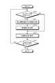
- FIGS. 6 to 9are flowcharts showing an example of a processing procedure executed by the information processing apparatus 100 according to the embodiment.
- the processing procedure shown in FIGS. 6 to 9is realized by the information processing apparatus 100 executing the program 3042.
- the control unit 302 of the information processing device 100determines whether or not the indicator 204 has been detected (step S10). For example, if the image captured by the image pickup unit 3080 provided in the information processing device 100 is analyzed and the indicator 204 can be detected, the process proceeds to step S11 (Yes in step S10), and the indicator 204 can be detected. If not, the process proceeds to step S13 as no (No in step S10).
- the control unit 302determines the information indicating the interpupillary distance (step S11). For example, the interpupillary distance indicated by the indicator 204 is determined from the color, pattern, shape, and the like of the indicator 204 detected in the image captured by the imaging unit 3080 of the information processing apparatus 100. When the process of step S11 is completed, the control unit 302 proceeds to step S12.
- the control unit 302changes the video display (step S12). For example, the distance between the image for the right eye and the image for the left eye for stereoscopic viewing displayed on the display unit 306306 of the information processing device 100 is adjusted. At the time of adjustment, the information indicating the interpupillary distance determined in step S11 is used. When the process of step S12 is completed, the control unit 302 proceeds to step S13.
- the control unit 302generates and displays an image (step S13). For example, the right-eye image and the left-eye image for stereoscopic viewing to be displayed on the display unit 306 of the information processing device 100 are generated, and the distance between the right-eye image and the left-eye image changed in step S12 is used as described above. The right-eye image and the left-eye image generated by the above are arranged, and the arranged image is displayed on the display unit 306. If the indicator 204 cannot be detected in step S10, the distance between the right-eye image and the left-eye image cannot be adjusted based on the information indicating the interpupillary distance in steps S11 and S12. The image for the left eye and the image for the right eye adjusted to the distance of are displayed on the display unit 306. When the process of step S13 is completed, the control unit 302 proceeds to step S14.
- the control unit 302determines whether or not the program 3042 has been completed (step S14). For example, it is determined whether or not the user has terminated the program 3042 being executed by the information processing apparatus 100, and if it is terminated, the program 3042 is terminated (Yes in step S14). If it is not completed, the process returns to step S10 as no (No in step S14).
- FIG. 7shows a processing procedure of a process of terminating the program 3042 by displaying that the indicator 204 is not detected when the indicator 204 is not detected. Since steps S21 to S24 of FIG. 7 are the same as steps S11 to S14 of FIG. 6, the description will not be repeated here.
- the control unit 302determines whether or not the indicator 204 has been detected (step S20). For example, if the image captured by the image pickup unit 3080 provided in the information processing device 100 is analyzed and the indicator 204 can be detected, the process proceeds to step S21 (Yes in step S20), and the indicator 204 can be detected. If not, the process proceeds to step S25 as no (No in step S20).
- the control unit 302displays the indicator 204 undetected (step S25). For example, the display unit 306 of the information processing apparatus 100 displays that the indicator 204 has not been detected.
- the control unit 302waits for the user's input and terminates the program 3042.
- FIG. 8shows a processing procedure for making it easier to detect the indicator 204 by turning on the light when the indicator 204 is not detected. Since steps S31 to S34 of FIG. 8 are the same as steps S11 to S14 of FIG. 6, the description will not be repeated here.
- the control unit 302determines whether or not the indicator 204 has been detected (step S30). For example, if the image captured by the image pickup unit 3080 provided in the information processing device 100 is analyzed and the indicator 204 can be detected, the process proceeds to step S31 (Yes in step S30), and the indicator 204 can be detected. If not, the process proceeds to step S35 as no (No in step S30).
- the control unit 302lights up (step S35). For example, the light emitting unit 310 provided in the information processing device 100 is made to emit light to illuminate the indicator 204. When the process of step S35 is completed, the control unit 302 proceeds to step S36.
- the control unit 302determines whether or not the indicator 204 has been detected after the lighting is turned on in step S35 (step S36). For example, if the image captured by the image pickup unit 3080 provided in the information processing device 100 is analyzed and the indicator 204 can be detected, the process proceeds to step S31 (Yes in step S36), and the indicator 204 can be detected. If not, the process proceeds to step S33 as no (No in step S36).
- the control unit 302determines whether or not the indicator 204 has been detected after the lighting is turned on in step S45 (step S46). For example, if the image captured by the image pickup unit 3080 provided in the information processing device 100 is analyzed and the indicator 204 can be detected, the process proceeds to step S41 (Yes in step S46), and the indicator 204 can be detected. If not, the process proceeds to step S47 as no (No in step S46).
- the control unit 302displays the indicator 204 undetected (step S47). For example, the display unit 306 of the information processing apparatus 100 displays that the indicator 204 has not been detected.
- the control unit 302waits for the user's input and terminates the program 3042.
- the present embodimentis not limited to such an embodiment.
- This embodimentcan be applied to various devices such as tablet-type devices, game machines, and computers such as PCs (Personal Computers).
- a plurality of moving image contents corresponding to various interpupillary distancesare stored in the storage unit of the information processing device 100, and moving image contents matching the information indicated by the indicator 204 detected by the detection unit 308 are displayed on the display unit 306.
- An embodiment of displayingis also conceivable.
- the information processing device 100transmits the information indicated by the indicator 204 detected by the detection unit 308 to the server, the server generates a moving image based on the information indicated by the indicator 204 that has been examined, and the server generates the moving image.
- An embodimentis also conceivable in which the generated moving image is transmitted to the information processing device 100, and the information processing device 100 displays the received moving image on the display unit 306.
- the information indicated by the indicator 204does not have to be the interpupillary distance.
- itmay be information for adjusting the display brightness of the display unit 306, or information on the cursor position for selecting a menu when the display unit 306 is a menu selection screen. ..
- An information processing devicethat can be used as a head-mounted display by being detachably held in a housing.
- a display unitthat displays images and
- a detection unitthat detects an indicator provided in the housing,
- a control unitthat controls an image displayed on the display unit based on the information indicated by the indicator detected by the detection unit.
- Information processing device equipped with(2) The information processing device according to (1), wherein the information indicated by the indicator is information on the positional relationship between the eyes of the user.
- the information processing deviceadjusts the distance between the left-eye image and the right-eye image based on the information indicated by the indicator.
- the detection unitincludes an imaging unit that captures an image of the indicator, and detects information indicated by the indicator based on an image acquired by the imaging unit, according to any one of (1) to (4).
- Information processing device(6)
- the information processing apparatusaccording to (5), further comprising a light emitting unit that illuminates the indicator.
- the information processing device according to (6), wherein the light emitting unitis the display unit.
- the imaging unitis an infrared camera.
- the information processing deviceaccording to (6), wherein the light emitting unit is an infrared light source.
- the light emitting unitemits light to illuminate the indicator.
- the information processing deviceaccording to any one of (6) to (8), wherein the image pickup unit re-images the indicator certified by the light emitting unit.
- the information processing deviceaccording to any one of (1) to (9), wherein the control unit displays the information indicated by the indicator on the display unit.
- a holding unitthat holds the information processing device detachably and An indicator arranged at a position that can be detected by the detection unit of the information processing apparatus held in the holding unit, an adjustment mechanism that allows the user to adjust the indicator, and an adjustment mechanism.
- a housing for a head-mounted display(12) The head-mounted display housing according to (11), wherein the information indicated by the indicator is information on the positional relationship between the eyes of the user. (13) The head-mounted display housing according to (11) or (12), wherein the adjustment mechanism is partially exposed to the outside of the housing and can be manually adjusted by the user. (14) Further, two lenses arranged at positions facing the display unit of the information processing apparatus held by the holding unit are further provided. The adjustment mechanism allows the user to adjust the distance between the two lenses.
- the indicatorindicates the distance between the two lenses as the information indicated by the indicator.
- the head-mounted display housingaccording to any one of (11) to (13).
- Head-mounted display housingOne of (11) to (15) further comprising a first moving mechanism for moving the indicator according to the position of the detection unit of the information processing apparatus held in the holding unit.
- the housing for the head-mounted displaydescribed.
- a head-mounted display systemincluding an information processing device including a detection unit and a display unit, and a housing that can be used as a head-mounted display by holding the information processing device detachably.
- the housingis A holding unit that holds the information processing device detachably and An indicator arranged at a position that can be detected by the detection unit of the information processing apparatus held in the holding unit, and an indicator.
- the information processing deviceA detection unit that detects the indicator provided in the housing and A control unit that controls an image displayed on the display unit based on the information indicated by the indicator detected by the detection unit.
- Information processing device102 CPU 104 GPU 106 RAM 108 VRAM 110 Storage 112 Display 114 Visible light camera 116 Infrared camera 118 Microphone 120 Touch sensor 122 Visible light floodlight 124 Infrared floodlight 126 Bus 200 Head mount display housing 202 Holder 204 Indicator 206 Lens 208 Adjustment mechanism 210 Auxiliary optical system 212 First moving mechanism 214 Second moving mechanism 302 Control unit 304 Storage unit 306 Display unit 308 Detection unit 310 Light emitting unit
Landscapes
- Physics & Mathematics (AREA)
- Engineering & Computer Science (AREA)
- General Physics & Mathematics (AREA)
- Multimedia (AREA)
- Signal Processing (AREA)
- Optics & Photonics (AREA)
- Computer Hardware Design (AREA)
- Theoretical Computer Science (AREA)
- User Interface Of Digital Computer (AREA)
- Position Input By Displaying (AREA)
Abstract
Description
Translated fromJapanese本開示は、情報処理装置、情報処理方法、ヘッドマウントディスプレイ用筐体、およびヘッドマウントディスプレイシステムに関する。This disclosure relates to an information processing device, an information processing method, a housing for a head-mounted display, and a head-mounted display system.
簡素な構成で視力矯正用の眼鏡を保持することができるヘッドマウントディスプレイに関する技術が開発されている。このような技術としては、例えば下記の特許文献1に記載の技術が挙げられる。Technology related to a head-mounted display that can hold eyeglasses for vision correction with a simple configuration has been developed. Examples of such a technique include the techniques described in Patent Document 1 below.
しかしながら、従来技術では、ユーザの瞳孔間距離等に応じて表示画像を制御するなどの工夫がなされておらず、個々のユーザに適したバーチャルリアリティー体験を提供することができていなかった。However, in the prior art, no device such as controlling the display image according to the interpupillary distance of the user has been made, and it has not been possible to provide a virtual reality experience suitable for each user.
本開示は、上記に鑑みてなされたものであって、個々のユーザに適したバーチャルリアリティー体験を提供することができる情報処理装置、ヘッドマウントディスプレイ用筐体、情報処理方法を提供することを目的とする。The present disclosure has been made in view of the above, and an object of the present disclosure is to provide an information processing device, a head-mounted display housing, and an information processing method capable of providing a virtual reality experience suitable for an individual user. And.
上述した課題を解決し、目的を達成するために、本開示において、筐体に着脱可能に保持されることでヘッドマウントディスプレイとして利用可能となる情報処理装置であって、画像を表示する表示部と、前記筐体に設けられたインジケータを検出する検出部と、前記検出部により検出された前記インジケータが示す情報に基づいて前記表示部に表示する画像を制御する制御部と、を備える情報処理装置、を提供する。In this disclosure, in order to solve the above-mentioned problems and achieve the object, it is an information processing device that can be used as a head-mounted display by being detachably held in a housing, and is a display unit that displays an image. Information processing including a detection unit that detects an indicator provided in the housing and a control unit that controls an image displayed on the display unit based on the information indicated by the indicator detected by the detection unit. The device, provided.
以下に添付図面を参照しながら、本開示の好適な実施の形態について詳細に説明する。なお、本明細書及び図面において、実質的に同一の機能構成を有する構成要素については、同一の符号を付することにより重複説明を省略する。Hereinafter, preferred embodiments of the present disclosure will be described in detail with reference to the accompanying drawings. In the present specification and the drawings, components having substantially the same functional configuration are designated by the same reference numerals, so that duplicate description will be omitted.
また、以下に示す項目順序に従って本開示を説明する。
1.一実施形態
1.1.ハードウェア構成
1.1-1.情報処理装置
1.1-2.ヘッドマウントディスプレイ用筐体
1.2.情報処理装置の機能構成
1.3.使用方法の概要
1.4.動作の説明(フローチャート)
2.その他の実施形態In addition, the present disclosure will be described according to the order of items shown below.
1. 1. One Embodiment 1.1. Hardware configuration 1.1-1. Information processing device 1.1-2. Head-mounted display housing 1.2. Functional configuration of information processing device 1.3. Outline of usage 1.4. Explanation of operation (flow chart)
2. Other embodiments
[1.一実施形態]
はじめに、一実施形態として、情報処理装置とヘッドマウントディスプレイ用筐体を組み合わせてヘッドマウントディスプレイとして利用する例について述べる。[1. One Embodiment]
First, as an embodiment, an example in which an information processing device and a head-mounted display housing are combined and used as a head-mounted display will be described.
[1.1.ハードウェア構成]
先ず、本開示におけるハードウェアの構成について説明する。以下では、本実施形態に係る情報処理装置及びヘッドマウントディスプレイ用筐体夫々のハードウェアの構成例を挙げる。[1.1. Hardware configuration]
First, the hardware configuration in the present disclosure will be described. In the following, a configuration example of the hardware of the information processing device and the housing for the head-mounted display according to the present embodiment will be given.
[1.1-1.情報処理装置]
図1A、図1B、図1C及び図1Dは、それぞれ、本実施形態における情報処理装置の外観表面、内観、外観裏面及びハードウェア構成図の一例を示す図である。本実施形態における情報処理装置100は、CPU(Central Processing Unit)102、GPU(Graphics Processing Unit)104、RAM(Random Access Memory)106、VRAM(Video RAM)108、ストレージ110、ディスプレイ112、可視光カメラ114、赤外線カメラ116、マイクロフォン118、タッチセンサ120、可視光投光装置122、赤外線投光装置124、等で構成されており、主にバス126を介して接続されている。[1.1-1. Information processing device]
1A, 1B, 1C, and 1D are diagrams showing an example of an external surface, an internal view, an external back surface, and a hardware configuration diagram of the information processing apparatus according to the present embodiment, respectively. The
本実施形態においてCPU102は、様々な演算を行う演算装置である。CPU102は、例えば、ストレージ110に記憶されたプログラム3042をRAM106にコピーしたうえで実行する。CPU102は、制御基板上に備わるSoC(System on a Chip)を構成する集積回路の一部であってもよい。In this embodiment, the
CPU102はまた、ディスプレイ112に表示する画像を制御する。例えば、VRAM108に記録された画像をディスプレイ112に表示するための命令をGPU104に発行し、ディスプレイ112に表示させる。The
CPU102はまた、GPU104、RAM106、VRAM108、ストレージ110、ディスプレイ112、可視光カメラ114、赤外線カメラ116、マイクロフォン118、タッチセンサ120、可視光投光装置122、赤外線投光装置124等の各種デバイスを制御し、各種デバイスからの入力を処理する。The
本実施形態において、GPU104は、画像処理のための演算を実行することを主目的とした演算装置であり、上述のようにCPU102からの命令を受けて演算を実行する。GPU104もまた、CPU102と同様、制御基板上に備わるSoC(System on a Chip)を構成する集積回路の一部であってもよい。In the present embodiment, the
本実施形態において、RAM106は、CPU102がプログラム3042を実行する際の作業領域として使用される主記憶装置である。RAM106もまた、CPU102やGPU104と同様、制御基板上に備わるSoCを構成する集積回路の一部であってもよい。In the present embodiment, the
本実施形態において、VRAM108は、主として上述のGPU104が画像処理のための演算をする際の作業領域として使用される主記憶装置である。VRAM108は上述のRAM106と共用の構成であるUMA(Unified Memory Architecture)であってもよい。In the present embodiment, the
本実施形態において、ストレージ110は、例えばHDD(Hard Disc Drive)やフラッシュメモリ等の補助記憶装置によって構成される。In the present embodiment, the
本実施形態におけるディスプレイ112は、GPU104等で生成した画像をユーザに視認可能に提示するものであり、例えば液晶ディスプレイや有機EL(Electro-Luminescence)ディスプレイ等によって実現される。The
本実施形態における可視光カメラ114は、レンズ206、イメージセンサ(CMOS、CCD等)及びカラーフィルタを少なくとも含むものである。可視光カメラ114は情報処理装置100の前面又は背面のどちらか一方に配置されていてもよいし、前面及び背面のどちらにも配置されていてもよい。さらに複数の焦点距離の可視光カメラ114が併設されていてもよい。The visible
本実施形態における赤外線カメラ116は、レンズ206、イメージセンサ(CMOS、CCD等)及び赤外線フィルタを少なくとも含むものである。赤外線カメラ116も可視光カメラ114と同様、情報処理装置100の前面又は背面のどちらか一方に配置されていてもよいし、前面及び背面のどちらにも配置されていてもよい。さらに複数の焦点距離の赤外線カメラ116が併設されていてもよいし、可視光カメラ114と併設されていてもよい。The
本実施形態におけるマイクロフォン118は、音を電気信号に変換する装置である。例えば、情報処理装置100を携帯電話として利用する場合に、ユーザ同士が会話することを可能にするために、マイクロフォン118がユーザの発話を電気信号に変換し、変換された電気信号は通話の相手に送信される。The
本実施形態におけるタッチセンサ120は、ユーザによる接触を検知する機能を有する。タッチセンサ120は、例えば、静電容量式や感圧式のタッチセンサ120であってよい。タッチセンサ120は、ユーザによる触れる、撫でる、叩く、押すなどの接触行為を検知することができ、当該接触行為に応じた動作を行うことが可能となる。タッチセンサ120は、情報処理装置100のディスプレイ112と一体となるように備わっていてもよい。The
本実施形態における可視光投光装置122は、キセノン管フラッシュやLEDフラッシュといった写真用フラッシュが挙げられる。可視光カメラ114で物体を撮像する際に、暗所のため光量が不足している場合においても、可視光投光装置122を発光させて可視光の光量を得ることができ、これにより撮像を可能にする。Examples of the visible
本実施形態における赤外線投光装置124は、赤外カメラで撮影するための赤外線ライトや赤外線ドットプロジェクタ等が挙げられる。赤外線投光装置124も可視光投光装置122と同様、赤外線カメラ116で物体を撮像する際に、暗所のため光量が不足している場合においても、赤外線投光装置124を発光させて赤外線の光量を得ることができ、これにより撮像を可能にする。Examples of the
ただし、本説明において例示した情報処理装置100は、単なる一例であり、スマートフォン、タブレット端末、携帯ゲーム機など、ディスプレイとカメラとを備える種々の情報処理装置を用いることが可能である。However, the
[1.1-2.ヘッドマウントディスプレイ用筐体]
図2A及び図2Bは、本実施形態におけるヘッドマウントディスプレイ用筐体200の一例を示しており、それぞれ外観図及び内観の概念図を示している。本実施形態におけるヘッドマウントディスプレイ用筐体(以下、単に筐体という)200は、保持部202、インジケータ204、レンズ206、調節機構208、補助光学系210、第一移動機構212、第二移動機構214、等で構成される。[1.1-2. Head-mounted display housing]
2A and 2B show an example of the head-mounted
本実施形態において保持部202は、ユーザの情報処理装置100を保持する。保持部202はまた、情報処理装置100を保持した際に、筐体200と情報処理装置100との間に生じた隙間から筐体200の内部に光が漏れ入ることを防止するために、保持した情報処理装置100を覆うように更にカバー(図示しない)を保持できるようにしてもよい。In the present embodiment, the holding
本実施形態においてインジケータ204は、ユーザの両眼の間の位置関係を示す。より具体的には、インジケータ204は、ユーザの瞳孔間距離を示してもよい。インジケータ204は、後述する調節機構208によって調節される。インジケータ204は、情報処理装置100の各種センサ(可視光カメラ114、赤外線カメラ116、マイクロフォン118、タッチセンサ120等)で検出可能な位置に設けられている。In the present embodiment, the
インジケータ204が示すユーザの両眼の間の位置関係は、例えば、ユーザがインジケータ204を調節することで変化する。例えば、インジケータ204は、ユーザによる調節に基づいて、外観の少なくとも一部である色彩、形状、模様、位置、回転角度、長さ又は大きさの少なくとも一つを変化させる。このインジケータ204の外観の少なくとも一部は、情報処理装置100の各種センサで検出可能である。The positional relationship between the eyes of the user indicated by the
なお、インジケータ204は、上記のような、外観にてユーザの両眼の間の位置関係を示す構成に限定されない。例えば、インジケータ204は、筐体200に取り付けられた情報処理装置100のタッチセンサ120と接触する構成であってもよい。この場合、ユーザによるインジケータ204の調節に基づいて、インジケータ204が接触するタッチセンサ120上の位置が変化してもよい。Note that the
また、インジケータ204はユーザの両眼の間の位置関係に応じた音を発生させる部材であってもよい。この場合、インジケータ204は、ユーザによる調節に基づいて、発生する音の周波数、音量、音の種類の少なくとも一つを変化させてもよい。Further, the
本実施形態においてレンズ206は、情報処理装置100を保持した際に、当該情報処理装置100のディスプレイ112に表示された画像を立体視することを可能にするレンズであり、右目用レンズ206R及び左目用レンズ206Lの二つのレンズを含む。ユーザが筐体200を頭部に装着した際に、ユーザの右目の正面に右目用レンズ206Rが、左目の正面に左目用レンズ206Lが配置されるように、筐体200に右目用レンズ206R及び左目用レンズ206Lが配置されている。In the present embodiment, the
本実施形態において調節機構208は、上述の右目用レンズ206R及び左目用レンズ206Lの間の距離を調節するとともに、インジケータ204を調節する。なお、上述のようにインジケータ204はユーザの両眼の間の位置関係を示す情報を示してもよい。ユーザの両眼の間の位置関係を示す情報は、具体的には、ユーザが調節した左右のレンズ206の光学中心間の距離を示す情報であってもよい。In the present embodiment, the
すなわち、インジケータ204は、調節機構208で調節する際に、左右のレンズ206間の距離を示すように、長さが変化してもよい。また、インジケータ204は、左右のレンズ206間の距離を示すように回転角度を変更してもよい。また、インジケータ204は、左右のレンズ206間の距離を示す周波数で音を鳴らしてもよい。また、インジケータ204は、左右のレンズ206間の距離を示すようにタッチセンサ120上の接触位置を変化させてもよい。That is, the length of the
本実施形態において補助光学系210は、インジケータ204を情報処理装置100の可視光カメラ114又は赤外線カメラ116で撮影する際、カメラとインジケータ204との間の距離がカメラの最短撮影距離よりも短いためにピントの合った撮像ができない場合に、ピントの合った撮像をする目的で設けられる補助的な光学系である。ここで、補助光学系210は、レンズでもよいし、プリズムでもよいし、ミラーでもよい。補助光学系210がレンズの場合、前述のカメラと補助光学系210のレンズとが一体となり、最短撮影距離が短くなったことでピントの合った撮像を可能にしてもよい。また、補助光学系210がプリズム又はミラーの場合、カメラからインジケータ204までの光路長を延長することでピントの合った撮像を可能としてもよい。In the present embodiment, when the
本実施形態において第一移動機構212は、インジケータ204の位置を移動させる。第一移動機構212は、ユーザの操作によって、筐体200に保持された情報処理装置100に備わるカメラから撮像可能な位置にインジケータ204を移動してもよい。すなわち、異なる種類の情報処理装置100であって異なる場所にカメラが配置されている情報処理装置100が筐体200に装着されたとしても、カメラの位置に合わせてインジケータ204を移動可能であるため、様々な種類の情報処理装置100を筐体200に装着可能としてもよい。In the present embodiment, the first moving
本実施形態において第二移動機構214は、補助光学系210の位置を移動させる。第二移動機構214は、ユーザの操作によって、筐体200に保持された情報処理装置100に備わるカメラからインジケータ204を撮像可能にするように補助光学系210を移動してもよい。すなわち、異なる種類の情報処理装置100であって異なる場所にカメラが配置されている情報処理装置100が筐体200に装着されたとしても、カメラ及びインジケータ204の位置に合わせて補助光学系210を移動可能なため、様々な種類の情報処理装置100を筐体200に装着して利用可能としてもよい。In the present embodiment, the
[1.2.機能構成]
次に、本実施形態に係る情報処理装置の機能構成例を挙げる。[1.2. Functional configuration]
Next, an example of the functional configuration of the information processing device according to the present embodiment will be given.
図3は本実施形態における情報処理装置100の機能構成の一例を示している。本実施形態における情報処理装置100の機能は制御部302、記憶部304、表示部306、検出部308、発光部310、等で構成される。FIG. 3 shows an example of the functional configuration of the
本実施形態において制御部302は、上述のCPU102によって記憶部304に記憶されたプログラム3042が実行されることにより実現される。記憶部304に記憶されたプログラム3042は、作業領域である上述のRAM106等の主記憶装置にコピーされた上でCPU102に実行される。In the present embodiment, the
制御部302はまた、表示部306に表示する画像を制御したりする。例えば、VRAM108に記録された画像を表示部306に表示するための命令をGPU104に発行し、表示部306に表示させる。The
制御部302はまた、検出部308に検出の命令をする。例えば、制御部302は、プログラム3042実行中の所与のタイミングで、インジケータ204を検出するよう検出部308に命令をし、検出結果を主記憶装置に保存する。The
制御部302はまた、検出部308で検出されたインジケータ204が示す情報データの読み取り制御及び読み取り結果の解析の制御をし、当該解析に基づいて表示部306に表示する画像を制御する。例えば、制御部302は、インジケータ204を検出部308で検出し、当該検出結果を解析してインジケータ204が示す情報を抽出し、当該抽出した情報に基づいて、表示部306に表示する画像を調節する。The
制御部302はまた、所定の条件が満たされているか否かを判定し、満たされている場合に、発光部310の発光を制御しつつ検出部308での検出を命令する。例えば、検出部308が撮像部3080を含み、撮像部3080でインジケータ204を撮像する場合に、所定の条件が満たされたと判定し、発光部310の発光を制御する。The
本実施形態において記憶部304は、例えばHDD(Hard Disc Drive)やフラッシュメモリ等の補助記憶装置であるストレージ110によって構成される。記憶部は、情報処理装置100の制御を行うプログラム3042、及び、インジケータ204が示す情報と表示部306に表示する画像の制御とを関連付ける対応テーブル3040を記憶している。具体的には、インジケータ204が示す瞳孔間距離と表示部306に表示する左目用画像と右目用画像の間の距離とを関連付ける対応テーブル3040を記憶している。In the present embodiment, the
記憶部に記憶されたプログラム3042は、上述のようにユーザからのプログラム実行開始指示があった場合に、RAM106等の作業領域にコピーされたうえでCPU102等に実行される。また、記憶部に記憶された対応テーブル3040は、検出部308によって検出されたインジケータ204の状態と併せて、表示部306に表示する画像を制御するために利用される。The
本実施形態における表示部306は、制御部302で生成した画像等をユーザに視認可能に提示するものであり、情報処理装置100のディスプレイ112によって実現される。The
表示部306は、記憶部に記憶された動画像情報等を、制御部302による制御によって表示してもよい。すなわち、制御部302は、記憶部に記憶された動画像ファイルを、ファイルストリームとして読みだしてVRAM108に逐次転送し、VRAM108上に転送された動画像であって、元の動画像ファイルの時間軸方向の一部の動画像を表示部306に表示するための命令を発行し、表示部306に表示してもよい。The
また、表示部306は、情報端末装置とも筐体200とも異なる外部のサーバ(図示しない)によって生成された動画像情報を、情報端末装置に備わる通信部(図示しない)を用いて受信し、制御部302による制御によって表示してもよい。Further, the
本実施形態における検出部308は、筐体200のインジケータ204を検出する。検出部308は、音、触覚、視覚などの知覚センサであってもよい。音のセンサとしてはマイクロフォン118が、触覚のセンサとしてはタッチセンサ120が、視覚のセンサとしては可視光カメラ114や赤外線カメラ116等が例として挙げられる。The
本実施形態における撮像部3080は、上述の検出部308に設けられた可視光カメラ114や赤外線カメラ116といったカメラである。撮像部3080は、レンズ、イメージセンサ(CMOS、CCD等)及びフィルタ(カラーフィルタ、赤外線フィルタ等)を少なくとも含むものである。撮像部3080は情報処理装置100の前面及び背面どちらにも配置されていてもよいし、さらに可視光カメラ114と赤外カメラが併設されていてもよい。The
本実施形態における発光部310は、上述のように情報処理装置100の可視光投光装置122や赤外線投光装置124によって実現される。撮像部3080で物体を撮像する際に、暗所で光量が不足している場合においても、発光部310である上記投光装置を発光させて光量を得ることにより撮像を可能にしてもよい。The light emitting unit 310 in the present embodiment is realized by the visible
また、発光部310は、上記のフラッシュ等に代えて、表示部306であってもよい。すなわち、表示部306が、液晶ディスプレイや有機EL(Electro-Luminescence)ディスプレイ等の発光するディスプレイ112で構成される場合、表示部306で表示する画像の内容を制御する等により、ディスプレイ112の光量を制御することができる。従って、撮像部3080で物体を撮像する際に、暗所で光量が不足している場合においても、ディスプレイ112から光量を得ることにより撮像が可能となる。Further, the light emitting unit 310 may be a
[1.3.使用方法の概要]
本実施形態において、情報処理装置100を筐体200と組み合わせてヘッドマウントディスプレイとして使用する方法の概要を以下に示す。[1.3. Overview of usage]
The outline of the method of using the
ユーザは初めに、ユーザの持つ情報処理装置100のプログラム3042を起動させる。このプログラム3042は、ヘッドマウントディスプレイとして情報処理装置100を利用するためのプログラム3042である。当該プログラム3042は、起動後、図5のように両眼立体視用の画像である右目用画像及び左目用画像が表示される。当該画像は、後述するように筐体200と組み合わせて初めてユーザは破綻のない立体視映像を体験することができる。The user first activates the
次にユーザは、プログラム3042を立ち上げた状態の情報処理装置100を、筐体200の保持部202で保持されるように筐体200に嵌め込む。この際、情報処理装置100の表示部306106が筐体200の内部に向くように嵌め込む。筐体200に情報処理装置100を嵌め込んだ後、筐体200に備わっているヘッドバンドを用いて、ユーザは自分の頭部に、情報処理装置100が嵌め込まれた筐体200を装着する。Next, the user fits the
筐体200には、情報処理装置100が保持部202に保持された状態の情報処理装置100の表示部306に対向する位置に2つのレンズ206が配置される。当該二つのレンズ206は夫々、右目用レンズ206R及び左目用レンズ206Lである。In the
ユーザが筐体200を頭部に装着すると、情報処理装置100の表示部306106の右目用画像が、筐体200に配置されている右目用レンズ206Rを通して、ユーザの右目で視聴可能となる。左目用画像も同様である。When the user attaches the
ユーザの瞳孔間距離と、上述の右目用レンズ206R及び左目用レンズ206Lの位置が適合していない場合、好適なバーチャルリアリティー体験を得ることができない。そのような場合、ユーザは、好適なバーチャルリアリティー体験を得るために、筐体200の外部に一部露出している調整機構を操作し、筐体200の右目用レンズ206R及び左目用レンズ206Lの間の距離を調節し、ユーザ自身の瞳孔間距離にレンズ206の光学中心間の距離を適合させる。If the user's interpupillary distance and the positions of the right eye lens 206R and the left eye lens 206L described above do not match, a suitable virtual reality experience cannot be obtained. In such a case, the user operates an adjustment mechanism partially exposed to the outside of the
調整機構は更に、内部に配置されているインジケータ204の色彩、形状、模様、位置、回転角度、長さ又は大きさの少なくとも一つを調節する。The adjustment mechanism further adjusts at least one of the color, shape, pattern, position, rotation angle, length or size of the
筐体200に保持されている情報処理装置100は、上記調節機構208によって調節されたインジケータ204を検出部308で検出する。例えば、検出部308の一部である撮像部3080に備わるカメラがインジケータ204を撮像することによって行われる。The
図4A及び図4Bは、ユーザが調整機構を調整することによりインジケータ204を移動させ、撮像部3080のカメラが検出するインジケータ204上の検出箇所を変化させる様子を示している。具体的には、図4Aのように、ユーザが調整機構を調整し、レンズ206間の間隔が小さくなる場合、インジケータ204が左側に移動する。図4Bは移動前後において撮像部3080が検出するインジケータ204上の場所がどのように変化するかを示している。撮像部3080のカメラによる撮像画像領域30802及び、撮像画像領域中の検出領域30804は筐体200に対して固定されている。このため、インジケータ204が左側に移動することによって、検出領域30804は、移動前のインジケータ204(A)上の右から4番目の模様の部分を検出していたところ、移動後は、移動後のインジケータ204(B)の右から三番目の模様の部分を検出することとなる。このように、レンズ206の移動と連動してインジケータ204が移動することにより、撮像部3080のカメラが検出するインジケータ204上の検出箇所が変化する。4A and 4B show how the user adjusts the adjustment mechanism to move the
以上、インジケータ204の領域が異なる模様によって領域が区分けされている場合について説明したが、インジケータ204の態様はこれに限られない。例えば、インジケータ204は、模様ではなく色彩で領域が分けられていてもよい。また、インジケータ204の色彩は、有限の数の色で分けられているのではなく、色彩のグラデーションで表現されていてもよい。また、インジケータ204は色彩によって色分けされているのではなく、白、黒及び白と黒の間のグレーの濃さを段階的に変化させたものであってもよいし、白から黒へグラデーションで表現されていてもよい。The case where the area of the
また、インジケータ204は色彩や白黒の濃淡が場所ごとに異なる検出するのではなく、形状によって検出してもよい。例えば、図4Cのように、一方は太く、他方は細い部材で構成されたインジケータ204であってもよい。この場合、調整機構での調整によってレンズ206と連動してインジケータ204が移動することで、カメラで撮像するインジケータ204の検出場所が変化する。具体的には、図4Bの場合と同様、図4Cの上図の状態から下図の状態にインジケータ204の位置が変化する場合、検出場所によって検出されるインジケータ204の幅は、広い検出結果から狭い検出結果に変化する。Further, the
なお、インジケータ204の形状は、太い幅から細い幅に連続的に変化するのではなく、階段状に非連続的に変化してもよい。Note that the shape of the
さらに、形状と色彩の組み合わせでもよい。この場合、お互いの検出結果を補完しあえるため、検出精度の向上が期待される。Furthermore, a combination of shape and color may be used. In this case, since the detection results of each other can be complemented with each other, improvement in detection accuracy is expected.
次に、検出部308で検出したインジケータ204の情報と、記憶部に記憶されている対応テーブル3040とを照合し、検出結果が示すユーザの両眼の間の位置関係の情報を取得し、記憶装置に記憶させる。具体的には、検出部308の一部である撮像部3080に備わるカメラによってインジケータ204が撮像され、当該撮像された画像が処理部で解析され、解析の結果得られた情報が、記憶部に記されている対応テーブル3040と照合され、照合された結果ユーザの瞳孔間距離の情報が取得され、当該ユーザの瞳孔間距離の情報が記憶装置に記憶される。Next, the information of the
なお、情報処理装置100は、前述の撮像の際に、筐体200の内部が暗いために十分な光量が得られず、インジケータ204の撮像が困難な場合、ユーザの瞳孔間距離の情報が得られなかったとして瞳孔間距離の初期値を設定してもよいし、発光部310を発光させてインジケータ204を照明して再度撮像し、インジケータ204が示すユーザの瞳孔間距離を検出してもよい。The
ここで、発光部310の発光は、撮像部3080が可視光カメラ114の場合、可視光投光装置122が好適である。制御部302は、発光部310である可視光投光装置122の発光を制御してインジケータ204を照らすとともに、撮像部3080である可視光カメラ114で発光により照らされたインジケータ204を撮像する制御を行う。Here, when the
また、発光部310の発光は、撮像部3080が可視光カメラ114であって、可視光投光装置122が存在しない場合や、ユーザにとって可視光投光装置122の発光が眩しく感じられてしまうなどの問題がある場合、表示部306の表示を調節することで行ってもよい。すなわち、表示部306のディスプレイ112の輝度を高める制御をしたり、表示内容を制御したりすることで光量を調整し、インジケータ204を照明してもよい。Further, as for the light emission of the light emitting unit 310, when the
また、発光部310の発光は、撮像部3080が赤外線カメラ116の場合、赤外線ライトや赤外線ドットプロジェクタなどの赤外線投光装置124であってもよい。この場合、ユーザは赤外線を見ることはできないため、赤外線投光装置124によって発光が眩しく感じられるといった問題を生じさせることなく、インジケータ204を照明するための光量を確保することができる。Further, when the
上述のように、調節機構208によって外観上変化するインジケータ204とカメラとの組み合わせによる検出について説明したが、インジケータ204と検出部308との組み合わせはこれに限られない。すなわち、インジケータ204がタッチセンサ120を反応させる部材であり、検出部308がタッチセンサ120である場合でも、上記カメラの場合と同様、調節機構208で調節したユーザの瞳孔間距離を検出可能である。具体的には、調節機構208で調節したユーザの瞳孔間距離がインジケータ204に反映され、当該インジケータ204がタッチするタッチセンサ120のタッチ座標が検出部308で読み取られ、読み取られた座標が記憶部に記憶されている対応テーブル3040と照合され、照合された結果ユーザの瞳孔間距離の情報が取得され、当該ユーザの瞳孔間距離の情報が記憶装置に記憶される。As described above, the detection by the combination of the
また、インジケータ204が所定の音を発する部材であり、検出部308がマイクロフォン118である場合でも、上記カメラの場合と同様、調節機構208で調節したユーザの瞳孔間距離を検出可能である。具体的には、調節機構208で調節したユーザの瞳孔間距離がインジケータ204に反映され、当該インジケータ204が発する音であって調節機構208の調節が反映された音が検出部308であるマイクロフォン118で検出され、検出された音が記憶部に記憶されている対応テーブル3040と照合され、照合された結果ユーザの瞳孔間距離の情報が取得され、当該ユーザの瞳孔間距離の情報が記憶部に記憶される。ここで、調節機構208の調節によってインジケータ204が発する音の周波数が変化するようにしてもよい。Further, even when the
次に、制御部302は、記憶装置に記憶された、ユーザの瞳孔間距離に関する情報を使用し、表示部306に表示する右目用画像と左目用画像の間の距離を調節する。すなわち、図5のように、様々なユーザの瞳孔間距離に応じて調節機構208を調節することで、ユーザの瞳孔間距離に適切なレンズ間距離及び表示部306の左目用画像と右目用画像の距離に調節される。具体的には、図5AのユーザAは、瞳孔間距離が短いので、このユーザAの瞳孔間距離に好適なバーチャルリアリティー体験を提供するためには、レンズ206間距離及び表示部306の画像間距離を短く設定する必要がある。ユーザAはヘッドマウントディスプレイが自分の瞳孔間距離に適合するように、調節機構208を用いてレンズ206間距離及び表示部306の画像間距離を、夫々距離a1及び距離a2に設定する。図5BのユーザBは、瞳孔間距離が人の平均であり、ユーザAよりも広いため、このユーザBは、好適なバーチャルリアリティー体験を得るため、調節機構208を用いてレンズ206間距離及び表示部306の画像間距離をユーザAのときよりも広い距離b1(>距離a1)及び距離b2(>距離a2)に設定する。図5CのユーザCは、瞳孔間距離がユーザBよりも更に広いため、ユーザCは、好適なバーチャルリアリティー体験を得るため、調節機構208を用いてレンズ206間距離及び表示部306の画像間距離をユーザBのときよりも更に広い距離c1(>距離b1)及び距離c2(>距離b2)に設定する。Next, the
このように、ユーザは一つの調節機構208を用いて、自分の瞳孔間距離に適するように、筐体200に情報処理装置100が保持された状態のまま、レンズ206間の距離及び表示部306に表示する左右の目用画像の間の距離を同時に調節することができる。したがって、瞳孔間距離の調節のために筐体200に保持されている状態の情報処理装置100を一旦取り外し、情報処理装置100に瞳孔間距離を設定した上で再度筐体200に情報処理装置100を取り付けるといった手間を省くことができる。In this way, the user uses one
更に制御部302は、記憶装置に記憶された、ユーザの瞳孔間距離に関する情報を表示部306に表示してもよい。このようにすれば、ユーザが自分自身の瞳孔間距離を知っている場合、ユーザは情報処理装置100の表示部306に表示される値を見ながら、調節機構208を用いて自分自身の瞳孔間距離に一致するように調節をすることができる。Further, the
筐体200が第一の情報処理装置100を保持し、取り外した後、第一の情報処理装置100と異なる第二の情報処理装置100を保持した場合、第一の情報処理装置100と第二の情報処理装置100のカメラ又は投光装置の情報処理装置上の位置が異なる場合があり得る。When the
この場合、第一の情報処理装置100と第二の情報処理装置100のカメラ又は投光装置の情報処理装置100上の位置が異なることに起因して、第一の情報処理装置100では筐体200のインジケータ204の検出が可能であったが、第二の情報処理装置100では不可能あるいは困難となるということが起こりうる。In this case, the first
このような情報処理装置100の物理的構成の差異を吸収するため、上述のように筐体200には第一移動機構212及び第二移動機構214が備わっていてもよい。In order to absorb such a difference in the physical configuration of the
更に、筐体200に第一移動機構212及び第二移動機構214が備わっていない場合においても、情報処理装置100の撮像画像のうち、インジケータ204の検出で使用する検出領域を、情報処理装置100のカメラの位置に基づいて変化させてもよい。Further, even when the
[1.4.動作の説明(フローチャート)]
次に、本実施形態に係る情報処理装置100の処理手順の一例について説明する。図6乃至図9は、実施形態に係る情報処理装置100が実行する処理手順の一例を示すフローチャートである。なお、図6乃至図9に示す処理手順は、情報処理装置100がプログラム3042を実行することによって実現される。[1.4. Explanation of operation (flow chart)]
Next, an example of the processing procedure of the
図6に示すように、情報処理装置100の制御部302は、インジケータ204を検出したか否かを判定する(ステップS10)。例えば、情報処理装置100に備わる撮像部3080によって撮像した画像を解析し、インジケータ204が検出可能であった場合、是として(ステップS10でYes)ステップS11に処理を進め、インジケータ204が検出可能でなかった場合、否として(ステップS10でNo)ステップS13に処理を進める。As shown in FIG. 6, the
制御部302は、瞳孔間距離を示す情報を判別する(ステップS11)。例えば、情報処理装置100の撮像部3080で撮像した画像中、検出されたインジケータ204の色彩、模様、形状等から、インジケータ204が示す瞳孔間距離を判別する。制御部302は、ステップS11の処理が終了すると、ステップS12に処理を進める。The
制御部302は、映像表示を変更する(ステップS12)。例えば、情報処理装置100の表示部306306に表示する立体視のための右目用画像と左目用画像の間の距離を調節する。調節の際には、ステップS11で判別された瞳孔間距離を示す情報を用いる。制御部302は、ステップS12の処理が終了すると、ステップS13に処理を進める。The
制御部302は、映像を生成し表示する(ステップS13)。例えば、情報処理装置100の表示部306に表示する立体視のための右目用画像と左目用画像を生成し、ステップS12で変更した右目用画像と左目用画像の間の距離に基づいて、前述の生成した右目用画像と左目用画像とを配置し、当該配置した映像を表示部306に表示する。なお、ステップS10でインジケータ204を検出できていない場合、ステップS11及びステップS12で瞳孔間距離を示す情報に基づく右目用画像と左目用画像との間の距離の調節を行うことができないため、規定の距離に調節された左目用画像と右目用画像を表示部306に表示する。制御部302は、ステップS13の処理が終了すると、ステップS14に処理を進める。The
制御部302は、プログラム3042を終了したか否かを判定する(ステップS14)。例えば、情報処理装置100で実行中のプログラム3042をユーザが終了したか否かを判定し、終了した場合、是として(ステップS14でYes)プログラム3042を終了する。終了していない場合、否として(ステップS14でNo)ステップS10の処理に戻る。The
図7では、インジケータ204が未検出だった場合、未検出である旨の表示をしてプログラム3042を終了する処理の処理手順を示している。図7のステップS21乃至ステップS24については、図6のステップS11乃至ステップS14と同様であるためここでは説明を繰り返さない。FIG. 7 shows a processing procedure of a process of terminating the
制御部302は、インジケータ204を検出したか否かを判定する(ステップS20)。例えば、情報処理装置100に備わる撮像部3080によって撮像した画像を解析し、インジケータ204が検出可能であった場合、是として(ステップS20でYes)ステップS21に処理を進め、インジケータ204が検出可能でなかった場合、否として(ステップS20でNo)ステップS25に処理を進める。The
制御部302は、インジケータ204未検出表示を行う(ステップS25)。例えば、情報処理装置100の表示部306に、インジケータ204が未検出であった旨表示する。制御部302はステップS25の処理が終了すると、ユーザの入力を待ち、プログラム3042の終了をする。The
図8では、インジケータ204が未検出だった場合、照明点灯してインジケータ204を検出しやすくする処理手順を示している。図8のステップS31乃至ステップS34について、図6のステップS11乃至ステップS14と同様であるためここでは説明を繰り返さない。FIG. 8 shows a processing procedure for making it easier to detect the
制御部302は、インジケータ204を検出したか否かを判定する(ステップS30)。例えば、情報処理装置100に備わる撮像部3080によって撮像した画像を解析し、インジケータ204が検出可能であった場合、是として(ステップS30でYes)ステップS31に処理を進め、インジケータ204が検出可能でなかった場合、否として(ステップS30でNo)ステップS35に処理を進める。The
制御部302は、照明点灯する(ステップS35)。例えば、情報処理装置100に備わる発光部310を発光させてインジケータ204を照明する。制御部302は、ステップS35の処理が終了すると、ステップS36に処理を進める。The
制御部302は、ステップS35で照明点灯した上で、インジケータ204を検出したか否かを判定する(ステップS36)。例えば、情報処理装置100に備わる撮像部3080によって撮像した画像を解析し、インジケータ204が検出可能であった場合、是として(ステップS36でYes)ステップS31に処理を進め、インジケータ204が検出可能でなかった場合、否として(ステップS36でNo)ステップS33に処理を進める。The
図9では、インジケータ204が未検出だった場合、照明点灯してインジケータ204を検出しやすくし、再度インジケータ204が未検出だった場合、未検出である旨の表示をしてプログラム3042を終了する処理の処理手順を示している。図9のステップS40乃至ステップS45について、図8のステップS30乃至ステップS45と同様であるためここでは説明を繰り返さない。In FIG. 9, when the
制御部302は、ステップS45で照明点灯した上で、インジケータ204を検出したか否かを判定する(ステップS46)。例えば、情報処理装置100に備わる撮像部3080によって撮像した画像を解析し、インジケータ204が検出可能であった場合、是として(ステップS46でYes)ステップS41に処理を進め、インジケータ204が検出可能でなかった場合、否として(ステップS46でNo)ステップS47に処理を進める。The
制御部302は、インジケータ204未検出表示を行う(ステップS47)。例えば、情報処理装置100の表示部306に、インジケータ204が未検出であった旨表示する。制御部302はステップS47の処理が終了すると、ユーザの入力を待ち、プログラム3042の終了をする。The
以上、本実施形態として、情報処理装置100を挙げて説明したが、本実施形態は、かかる形態に限られない。本実施形態は、例えば、タブレット型の装置や、ゲーム機、PC(Personal Computer)などのコンピュータなど、様々な機器に適用することができる。Although the
[2.その他の実施形態]
以上、第一の実施形態を説明したが、次のような他の実施形態も考えられる。[2. Other embodiments]
Although the first embodiment has been described above, the following other embodiments are also conceivable.
情報処理装置100の記憶部に、様々な瞳孔間距離に対応した複数の動画コンテンツが保存されており、検出部308によって検出されたインジケータ204が示す情報に適合する動画像コンテンツを表示部306に表示する、という実施形態も考えられる。A plurality of moving image contents corresponding to various interpupillary distances are stored in the storage unit of the
また、情報処理装置100は、検出部308によって検出されたインジケータ204が示す情報をサーバに送信し、上記サーバは受診した上記インジケータ204が示す情報に基づいて動画像を生成し、上記サーバは上記生成した動画像を情報処理装置100に送信し、上記情報処理装置100は受信した動画像を表示部306に表示する、という実施形態も考えられる。Further, the
また、インジケータ204が示す情報は瞳孔間距離でなくても構わない。例えば表示部306の表示の明るさの調節のための情報であったり、表示部306がメニュー選択画面だった場合にメニューを選択するためのカーソル位置の情報であったり、という実施形態も考えられる。Also, the information indicated by the
以上、添付図面を参照しながら本開示の好適な実施形態について詳細に説明したが、本開示の技術的範囲はかかる例に限定されない。本開示の技術分野における通常の知識を有する者であれば、請求の範囲に記載された技術的思想の範疇内において、各種の変更例または修正例に想到し得ることは明らかであり、これらについても、当然に本開示の技術的範囲に属するものと了解される。Although the preferred embodiments of the present disclosure have been described in detail with reference to the accompanying drawings, the technical scope of the present disclosure is not limited to such examples. It is clear that anyone with ordinary knowledge in the technical field of the present disclosure may come up with various modifications or modifications within the scope of the technical ideas set forth in the claims. Is, of course, understood to belong to the technical scope of the present disclosure.
上述した構成は、本実施形態の一例を示すものであり、当然に、本開示の技術的範囲に属するものである。The above-mentioned configuration shows an example of the present embodiment, and naturally belongs to the technical scope of the present disclosure.
また、本明細書に記載された効果は、あくまで説明的または例示的なものであって限定的ではない。つまり、本開示に係る技術は、上記の効果とともに、または上記の効果に代えて、本明細書の記載から当業者には明らかな他の効果を奏しうる。Further, the effects described in the present specification are merely explanatory or exemplary and are not limited. That is, the techniques according to the present disclosure may exhibit other effects apparent to those skilled in the art from the description herein, in addition to or in place of the above effects.
なお、以下のような構成も本開示の技術的範囲に属する。
(1)
筐体に着脱可能に保持されることでヘッドマウントディスプレイとして利用可能となる情報処理装置であって、
画像を表示する表示部と、
前記筐体に設けられたインジケータを検出する
検出部と、
前記検出部により検出された前記インジケータが示す情報に基づいて前記表示部に表示する画像を制御する制御部と、
を備える情報処理装置。
(2)
前記インジケータが示す情報は、ユーザの両眼の間の位置関係の情報である、(1)に記載の情報処理装置。
(3)
前記表示部に表示する画像は、左目用画像及び右目用画像を含む、(2)又は(3)に記載の情報処理装置。
(4)
前記制御部は、前記インジケータが示す情報に基づいて、前記左目用画像及び右目用画像の間の距離を調節する、(3)に記載の情報処理装置。
(5)
前記検出部は、前記インジケータを撮像する撮像部を含み、前記撮像部で取得された画像に基づいて前記インジケータが示す情報を検出する、(1)乃至(4)のいずれか1つに記載の情報処理装置。
(6)
前記インジケータを照明する発光部をさらに備える、(5)に記載の情報処理装置。
(7)
前記発光部は、前記表示部である、(6)に記載の情報処理装置。
(8)
前記撮像部は、赤外カメラであり、
前記発光部は、赤外光源である、(6)に記載の情報処理装置。
(9)
前記発光部は、前記撮像部で取得された前記画像から前記インジケータが示す情報が検出されなかった場合、前記インジケータを照明するために発光し、
前記撮像部は、前記発光部により証明された前記インジケータを再度撮像する、(6)乃至(8)のいずれか1つに記載の情報処理装置。
(10)
前記制御部は、前記インジケータが示す情報を前記表示部に表示させる、(1)乃至(9)のいずれか1つに記載の情報処理装置。
(11)
検出部及び表示部を備える情報処理装置を着脱可能に保持することでヘッドマウントディスプレイとして利用可能となる筐体であって、
前記情報処理装置を着脱可能に保持する保持部と、
前記保持部に保持された状態の前記情報処理装置の前記検出部によって検出可能な位置に配置されたインジケータと
ユーザに前記インジケータを調節させる調節機構と、
を備える
ヘッドマウントディスプレイ用筐体。
(12)
前記インジケータが示す情報は、ユーザの両眼の間の位置関係の情報である、(11)に記載のヘッドマウントディスプレイ用筐体。
(13)
前記調節機構は一部が筐体外に露出しており、ユーザが手動で調節できる、(11)又は(12)に記載のヘッドマウントディスプレイ用筐体。
(14)
前記保持部に保持された状態の前記情報処理装置の前記表示部に対向する位置に配置された2つのレンズをさらに備え、
前記調節機構は、ユーザに前記2つのレンズ間の距離を調節させ、
前記インジケータは、前記インジケータが示す情報として前記2つのレンズ間の距離を示す、
(11)乃至(13)のいずれか1つに記載のヘッドマウントディスプレイ用筐体。
(15)
前記インジケータは、前記調節機構による調節に応じて、色、形状、模様、位置、回転角度、長さ又は大きさの少なくとも一つが変化する、(11)乃至(14)のいずれか1つに記載のヘッドマウントディスプレイ用筐体。
(16)
前記保持部に保持された状態の前記情報処理装置の前記検出部の位置に応じて前記インジケータを移動させるための第1移動機構をさらに備える、(11)乃至(15)のいずれか1つに記載のヘッドマウントディスプレイ用筐体。
(17)
前記保持部に保持された状態の前記情報処理装置の前記検出部と前記インジケータとの間に配置された補助光学系をさらに備える、(11)乃至(16)のいずれか1つに記載のヘッドマウントディスプレイ用筐体。
(18)
前記保持部に保持された状態の前記情報処理装置の前記検出部の位置に応じて前記補助光学系を移動させるための第2移動機構をさらに備える、(17)に記載のヘッドマウントディスプレイ用筐体。
(19)
検出部と表示部とを備える情報処理装置と、前記情報処理装置を着脱可能に保持することでヘッドマウントディスプレイとして利用可能となる筐体とを備えるヘッドマウントディスプレイシステムであって、
前記筐体は、
前記情報処理装置を着脱可能に保持する保持部と、
前記保持部に保持された状態の前記情報処理装置の前記検出部によって検出可能な位置に配置されるインジケータと、
ユーザに前記インジケータを調節させる調節機構と、
を備え、
前記情報処理装置は、
前記筐体に設けられた前記インジケータを検出する検出部と、
前記検出部により検出された前記インジケータが示す情報に基づいて前記表示部に表示する画像を制御する制御部と、
を備える
ヘッドマウントディスプレイシステム。
(20)
表示部を備え、筐体に着脱可能に保持されることでヘッドマウントディスプレイとして利用可能となる情報処理装置において実行される情報処理方法であって、
前記筐体に設けられたインジケータを検出し、
検出された前記インジケータが示す情報に基づいて前記表示部に表示する画像を制御する
ことを含む情報処理方法。The following configurations also belong to the technical scope of the present disclosure.
(1)
An information processing device that can be used as a head-mounted display by being detachably held in a housing.
A display unit that displays images and
A detection unit that detects an indicator provided in the housing,
A control unit that controls an image displayed on the display unit based on the information indicated by the indicator detected by the detection unit.
Information processing device equipped with.
(2)
The information processing device according to (1), wherein the information indicated by the indicator is information on the positional relationship between the eyes of the user.
(3)
The information processing device according to (2) or (3), wherein the image displayed on the display unit includes an image for the left eye and an image for the right eye.
(4)
The information processing device according to (3), wherein the control unit adjusts the distance between the left-eye image and the right-eye image based on the information indicated by the indicator.
(5)
The detection unit includes an imaging unit that captures an image of the indicator, and detects information indicated by the indicator based on an image acquired by the imaging unit, according to any one of (1) to (4). Information processing device.
(6)
The information processing apparatus according to (5), further comprising a light emitting unit that illuminates the indicator.
(7)
The information processing device according to (6), wherein the light emitting unit is the display unit.
(8)
The imaging unit is an infrared camera.
The information processing device according to (6), wherein the light emitting unit is an infrared light source.
(9)
When the information indicated by the indicator is not detected from the image acquired by the imaging unit, the light emitting unit emits light to illuminate the indicator.
The information processing device according to any one of (6) to (8), wherein the image pickup unit re-images the indicator certified by the light emitting unit.
(10)
The information processing device according to any one of (1) to (9), wherein the control unit displays the information indicated by the indicator on the display unit.
(11)
A housing that can be used as a head-mounted display by detachably holding an information processing device including a detection unit and a display unit.
A holding unit that holds the information processing device detachably and
An indicator arranged at a position that can be detected by the detection unit of the information processing apparatus held in the holding unit, an adjustment mechanism that allows the user to adjust the indicator, and an adjustment mechanism.
A housing for a head-mounted display.
(12)
The head-mounted display housing according to (11), wherein the information indicated by the indicator is information on the positional relationship between the eyes of the user.
(13)
The head-mounted display housing according to (11) or (12), wherein the adjustment mechanism is partially exposed to the outside of the housing and can be manually adjusted by the user.
(14)
Further, two lenses arranged at positions facing the display unit of the information processing apparatus held by the holding unit are further provided.
The adjustment mechanism allows the user to adjust the distance between the two lenses.
The indicator indicates the distance between the two lenses as the information indicated by the indicator.
The head-mounted display housing according to any one of (11) to (13).
(15)
The indicator according to any one of (11) to (14), wherein at least one of color, shape, pattern, position, rotation angle, length or size changes according to the adjustment by the adjustment mechanism. Head-mounted display housing.
(16)
One of (11) to (15) further comprising a first moving mechanism for moving the indicator according to the position of the detection unit of the information processing apparatus held in the holding unit. The housing for the head-mounted display described.
(17)
The head according to any one of (11) to (16), further comprising an auxiliary optical system arranged between the detection unit and the indicator of the information processing apparatus held in the holding unit. Housing for mounted display.
(18)
The head-mounted display housing according to (17), further comprising a second moving mechanism for moving the auxiliary optical system according to the position of the detection unit of the information processing apparatus held by the holding unit. body.
(19)
A head-mounted display system including an information processing device including a detection unit and a display unit, and a housing that can be used as a head-mounted display by holding the information processing device detachably.
The housing is
A holding unit that holds the information processing device detachably and
An indicator arranged at a position that can be detected by the detection unit of the information processing apparatus held in the holding unit, and an indicator.
An adjustment mechanism that allows the user to adjust the indicator,
With
The information processing device
A detection unit that detects the indicator provided in the housing and
A control unit that controls an image displayed on the display unit based on the information indicated by the indicator detected by the detection unit.
Head-mounted display system with.
(20)
It is an information processing method executed in an information processing device that has a display unit and can be used as a head-mounted display by being detachably held in a housing.
The indicator provided on the housing is detected and
An information processing method including controlling an image displayed on the display unit based on the detected information indicated by the indicator.
100 情報処理装置
102 CPU
104 GPU
106 RAM
108 VRAM
110 ストレージ
112 ディスプレイ
114 可視光カメラ
116 赤外線カメラ
118 マイクロフォン
120 タッチセンサ
122 可視光投光装置
124 赤外線投光装置
126 バス
200 ヘッドマウントディスプレイ用筐体
202 保持部
204 インジケータ
206 レンズ
208 調節機構
210 補助光学系
212 第一移動機構
214 第二移動機構
302 制御部
304 記憶部
306 表示部
308 検出部
310 発光部100
104 GPU
106 RAM
108 VRAM
110
Claims (20)
Translated fromJapanese画像を表示する表示部と、
前記筐体に設けられたインジケータを検出する検出部と、
前記検出部により検出された前記インジケータが示す情報に基づいて前記表示部に表示する画像を制御する制御部と、
を備える情報処理装置。An information processing device that can be used as a head-mounted display by being detachably held in a housing.
A display unit that displays images and
A detection unit that detects an indicator provided in the housing and
A control unit that controls an image displayed on the display unit based on the information indicated by the indicator detected by the detection unit.
Information processing device equipped with.
前記発光部は、赤外光源である、請求項6に記載の情報処理装置。The imaging unit is an infrared camera.
The information processing device according to claim 6, wherein the light emitting unit is an infrared light source.
前記撮像部は、前記発光部により照明された前記インジケータを再度撮像する、請求項6乃至8のいずれか1つに記載の情報処理装置。When the information indicated by the indicator is not detected from the image acquired by the imaging unit, the light emitting unit emits light to illuminate the indicator.
The information processing device according to any one of claims 6 to 8, wherein the imaging unit re-images the indicator illuminated by the light emitting unit.
前記情報処理装置を着脱可能に保持する保持部と、
前記保持部に保持された状態の前記情報処理装置の前記検出部によって検出可能な位置に配置されたインジケータと、
ユーザに前記インジケータを調節させる調節機構と、
を備える
ヘッドマウントディスプレイ用筐体。A housing that can be used as a head-mounted display by detachably holding an information processing device including a detection unit and a display unit.
A holding unit that holds the information processing device detachably and
An indicator arranged at a position that can be detected by the detection unit of the information processing apparatus held in the holding unit, and
An adjustment mechanism that allows the user to adjust the indicator,
A housing for a head-mounted display.
前記調節機構は、ユーザに前記2つのレンズ間の距離を調節させ、
前記インジケータは、前記インジケータが示す情報として前記2つのレンズ間の距離を示す、
請求項11乃至13のいずれか1つに記載のヘッドマウントディスプレイ用筐体。Further, two lenses arranged at positions facing the display unit of the information processing apparatus held by the holding unit are further provided.
The adjustment mechanism allows the user to adjust the distance between the two lenses.
The indicator indicates the distance between the two lenses as the information indicated by the indicator.
The head-mounted display housing according to any one of claims 11 to 13.
前記筐体は、
前記情報処理装置を着脱可能に保持する保持部と、
前記保持部に保持された状態の前記情報処理装置の前記検出部によって検出可能な位置に配置されるインジケータと、
ユーザに前記インジケータを調節させる調節機構と、
を備え、
前記情報処理装置は、
前記筐体に設けられた前記インジケータを検出する検出部と、
前記検出部により検出された前記インジケータが示す情報に基づいて前記表示部に表示する画像を制御する制御部と、
を備える
ヘッドマウントディスプレイシステム。A head-mounted display system including an information processing device including a detection unit and a display unit, and a housing that can be used as a head-mounted display by holding the information processing device detachably.
The housing is
A holding unit that holds the information processing device detachably and
An indicator arranged at a position that can be detected by the detection unit of the information processing apparatus held in the holding unit, and an indicator.
An adjustment mechanism that allows the user to adjust the indicator,
With
The information processing device
A detection unit that detects the indicator provided in the housing and
A control unit that controls an image displayed on the display unit based on the information indicated by the indicator detected by the detection unit.
Head-mounted display system with.
前記筐体に設けられたインジケータを検出し、
検出された前記インジケータが示す情報に基づいて前記表示部に表示する画像を制御する
ことを含む情報処理方法。It is an information processing method executed in an information processing device that has a display unit and can be used as a head-mounted display by being detachably held in a housing.
The indicator provided on the housing is detected and
An information processing method including controlling an image displayed on the display unit based on the detected information indicated by the indicator.
Priority Applications (4)
| Application Number | Priority Date | Filing Date | Title |
|---|---|---|---|
| US17/997,608US11933988B2 (en) | 2020-05-07 | 2021-04-23 | Information processing apparatus, information processing method, head mounted display housing, and head mounted display system |
| JP2022519929AJPWO2021225082A1 (en) | 2020-05-07 | 2021-04-23 | |
| DE112021002658.5TDE112021002658T5 (en) | 2020-05-07 | 2021-04-23 | Information processing apparatus, information processing method, housing for head mounted display and head mounted display system |
| CN202180032127.XACN115516853A (en) | 2020-05-07 | 2021-04-23 | Information processing device, information processing method, casing for head-mounted display, and head-mounted display system |
Applications Claiming Priority (2)
| Application Number | Priority Date | Filing Date | Title |
|---|---|---|---|
| JP2020082282 | 2020-05-07 | ||
| JP2020-082282 | 2020-05-07 |
Publications (1)
| Publication Number | Publication Date |
|---|---|
| WO2021225082A1true WO2021225082A1 (en) | 2021-11-11 |
Family
ID=78467914
Family Applications (1)
| Application Number | Title | Priority Date | Filing Date |
|---|---|---|---|
| PCT/JP2021/016461CeasedWO2021225082A1 (en) | 2020-05-07 | 2021-04-23 | Information processing device, information processing method, housing for head-mounted display, and head-mounted display system |
Country Status (5)
| Country | Link |
|---|---|
| US (1) | US11933988B2 (en) |
| JP (1) | JPWO2021225082A1 (en) |
| CN (1) | CN115516853A (en) |
| DE (1) | DE112021002658T5 (en) |
| WO (1) | WO2021225082A1 (en) |
Citations (7)
| Publication number | Priority date | Publication date | Assignee | Title |
|---|---|---|---|---|
| JPS62239784A (en)* | 1986-04-11 | 1987-10-20 | Sanyo Electric Co Ltd | 3D television control system |
| JP2011155631A (en)* | 2010-01-25 | 2011-08-11 | Samsung Electronics Co Ltd | Display device and method of driving the same, and shutter type three-dimensional glasses and method of driving the same |
| WO2014057557A1 (en)* | 2012-10-11 | 2014-04-17 | Tahara Hirofumi | Video observation system |
| JP2017528935A (en)* | 2014-05-30 | 2017-09-28 | ソニー インタラクティブ エンタテインメント アメリカ リミテッド ライアビリテイ カンパニー | Head mounted device (HMD) system having an interface with a mobile computing device for rendering virtual reality content |
| WO2018150722A1 (en)* | 2017-02-20 | 2018-08-23 | シャープ株式会社 | Head mount display |
| US20190273911A1 (en)* | 2018-03-01 | 2019-09-05 | Google Llc | Active lcd shutters for virtual and augmented reality low persistence |
| JP2020057864A (en)* | 2018-09-28 | 2020-04-09 | 株式会社Nttドコモ | Terminal mounting device and portable terminal |
Family Cites Families (5)
| Publication number | Priority date | Publication date | Assignee | Title |
|---|---|---|---|---|
| US10234699B2 (en) | 2013-11-26 | 2019-03-19 | Sony Corporation | Head-mounted display |
| KR102439993B1 (en)* | 2015-02-27 | 2022-09-06 | 삼성전자주식회사 | Electronic device with heat dissipation device and control method thereof |
| CN106125307A (en)* | 2016-06-28 | 2016-11-16 | 姜冬英 | Outer hanging panel Formula V R glasses and adjust the method that shows of screen and screen display device |
| CN205787390U (en)* | 2016-06-28 | 2016-12-07 | 姜冬英 | Outer hanging panel Formula V R glasses |
| US20200275087A1 (en)* | 2019-02-25 | 2020-08-27 | Kazuhiro Asakura | Computer-readable non-transitory storage medium, web server, and calibration method for interpupillary distance |
- 2021
- 2021-04-23WOPCT/JP2021/016461patent/WO2021225082A1/ennot_activeCeased
- 2021-04-23USUS17/997,608patent/US11933988B2/enactiveActive
- 2021-04-23JPJP2022519929Apatent/JPWO2021225082A1/janot_activeCeased
- 2021-04-23CNCN202180032127.XApatent/CN115516853A/ennot_activeWithdrawn
- 2021-04-23DEDE112021002658.5Tpatent/DE112021002658T5/enactivePending
Patent Citations (7)
| Publication number | Priority date | Publication date | Assignee | Title |
|---|---|---|---|---|
| JPS62239784A (en)* | 1986-04-11 | 1987-10-20 | Sanyo Electric Co Ltd | 3D television control system |
| JP2011155631A (en)* | 2010-01-25 | 2011-08-11 | Samsung Electronics Co Ltd | Display device and method of driving the same, and shutter type three-dimensional glasses and method of driving the same |
| WO2014057557A1 (en)* | 2012-10-11 | 2014-04-17 | Tahara Hirofumi | Video observation system |
| JP2017528935A (en)* | 2014-05-30 | 2017-09-28 | ソニー インタラクティブ エンタテインメント アメリカ リミテッド ライアビリテイ カンパニー | Head mounted device (HMD) system having an interface with a mobile computing device for rendering virtual reality content |
| WO2018150722A1 (en)* | 2017-02-20 | 2018-08-23 | シャープ株式会社 | Head mount display |
| US20190273911A1 (en)* | 2018-03-01 | 2019-09-05 | Google Llc | Active lcd shutters for virtual and augmented reality low persistence |
| JP2020057864A (en)* | 2018-09-28 | 2020-04-09 | 株式会社Nttドコモ | Terminal mounting device and portable terminal |
Also Published As
| Publication number | Publication date |
|---|---|
| CN115516853A (en) | 2022-12-23 |
| JPWO2021225082A1 (en) | 2021-11-11 |
| US20230161164A1 (en) | 2023-05-25 |
| DE112021002658T5 (en) | 2023-03-30 |
| US11933988B2 (en) | 2024-03-19 |
Similar Documents
| Publication | Publication Date | Title |
|---|---|---|
| US11917126B2 (en) | Systems and methods for eye tracking in virtual reality and augmented reality applications | |
| CN114730094B (en) | Artificial reality system with varifocal display of artificial reality content | |
| CN108700932B (en) | Wearable device capable of eye tracking | |
| US9967487B2 (en) | Preparation of image capture device in response to pre-image-capture signal | |
| JP2019091051A (en) | Display device, and display method using focus display and context display | |
| JP6149403B2 (en) | Display device and control method of display device | |
| JP7218376B2 (en) | Eye-tracking method and apparatus | |
| CN108398788A (en) | Eye tracking apparatus and virtual reality imaging device | |
| JP7145944B2 (en) | Display device and display method using means for providing visual cues | |
| CN113382228A (en) | Head-mounted display devices and head-mounted display systems | |
| WO2021210235A1 (en) | Electronic device | |
| WO2021225082A1 (en) | Information processing device, information processing method, housing for head-mounted display, and head-mounted display system | |
| CN117724240A (en) | Eye tracking system with in-plane illumination | |
| CN118694912A (en) | Gaze-aware tone mapping with adaptive glint | |
| JP2013181992A (en) | Illuminating device | |
| CN117478863A (en) | Image processing apparatus, image processing method, recording medium, and glasses type information display apparatus |
Legal Events
| Date | Code | Title | Description |
|---|---|---|---|
| 121 | Ep: the epo has been informed by wipo that ep was designated in this application | Ref document number:21800958 Country of ref document:EP Kind code of ref document:A1 | |
| ENP | Entry into the national phase | Ref document number:2022519929 Country of ref document:JP Kind code of ref document:A | |
| 122 | Ep: pct application non-entry in european phase | Ref document number:21800958 Country of ref document:EP Kind code of ref document:A1 |