WO2021218256A1 - Control system for automatic edge banding machine - Google Patents
Control system for automatic edge banding machineDownload PDFInfo
- Publication number
- WO2021218256A1 WO2021218256A1PCT/CN2021/074337CN2021074337WWO2021218256A1WO 2021218256 A1WO2021218256 A1WO 2021218256A1CN 2021074337 WCN2021074337 WCN 2021074337WWO 2021218256 A1WO2021218256 A1WO 2021218256A1
- Authority
- WO
- WIPO (PCT)
- Prior art keywords
- flat
- finishing
- profiling
- cut
- scraping
- Prior art date
- Legal status (The legal status is an assumption and is not a legal conclusion. Google has not performed a legal analysis and makes no representation as to the accuracy of the status listed.)
- Ceased
Links
Images


Classifications
- B—PERFORMING OPERATIONS; TRANSPORTING
- B27—WORKING OR PRESERVING WOOD OR SIMILAR MATERIAL; NAILING OR STAPLING MACHINES IN GENERAL
- B27N—MANUFACTURE BY DRY PROCESSES OF ARTICLES, WITH OR WITHOUT ORGANIC BINDING AGENTS, MADE FROM PARTICLES OR FIBRES CONSISTING OF WOOD OR OTHER LIGNOCELLULOSIC OR LIKE ORGANIC MATERIAL
- B27N7/00—After-treatment, e.g. reducing swelling or shrinkage, surfacing; Protecting the edges of boards against access of humidity
Definitions
- the automatic edge banding machineis a machine used by furniture factories to process panels. Each component has a high degree of automation. At present, there are many custom-made furniture on the market. There are various sizes of panels in each batch of orders, and the edge bands are in color and thickness. However, most of the edge banding machines on the market are ordinary edge banding machines, which cannot be accurately controlled, which hinders the edge banding efficiency of the edge banding machine.
- the edge banding machineis a common woodworking machine that can realize the mechanized operation of edge banding. It applies glue on the edge band, and then glues the glued edge band on the side of the board.
- a belt pressing deviceis required to press the side belt so that the side belt can be firmly glued to the side of the board.
- the existing belt pressing devicepresses the special-shaped edges of different plates, it is necessary to manually adjust the belt pressing angle of the belt pressing parts or replace the belt pressing parts with different structures. It is inconvenient to adjust or replace the belt pressing parts, which increases the operator's Labor intensity. Therefore, the shortcomings are very obvious, and a solution is urgently needed.
- a control system of an automatic edge banding machineis provided.
- the edge banding machineincludes a conveying mechanism, a tape cutting mechanism and a glue supply mechanism arranged around the conveying mechanism.
- the feeding directionis arranged in sequence around the conveyor mechanism, the feeding mechanism, the flat cutting mechanism, the finishing mechanism, the profiling trimming mechanism, the scraping mechanism, the belt feeding driving mechanism, the flat cutting driving mechanism, the finishing driving mechanism, The profiling trimming drive mechanism and the scraping drive mechanism; the tape supply driving mechanism is used to drive the tape supply mechanism, and the tape supply mechanism is used to transport the material tape from the external tape storage mechanism to the tape cutting mechanism and the glue supply mechanism.
- the flat-cutting head drive mechanismis used to drive the flat-cutting head mechanism, the flat-cutting head mechanism is used to cut the workpiece on the conveying mechanism;
- the finishing drive mechanismis used to drive the finishing mechanism, The finishing mechanism is used to cut a circular arc on the workpiece on the conveying mechanism;
- the profiling and trimming drive mechanismis used to drive the profiling and trimming mechanism, and the profiling and trimming mechanism is used to copy the workpiece on the conveying mechanism. Trimming;
- the scraping drive mechanismis used to drive the scraping mechanism, and the scraping mechanism is used to align the arc edge of the workpiece on the conveying mechanism;
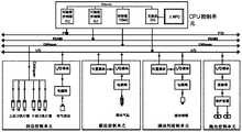
- the control systemincludes a CPU controller, a communication line connected to the CPU controller, a tape supply control unit connected to the communication line for one-way control, a flat cutting head control unit, a finishing control unit, and a profile trimming control unit And scraping control unit;
- the tape supply control unitis connected to the tape supply drive mechanism for one-way control
- the flat cutting head control unitis connected to the flat head drive mechanism for one-way control
- the finishing control unitis one-way controlled with the finishing drive mechanism.
- the edge trimming control unitis connected with the edge trimming drive mechanism in one-way control
- the edge scraping control unitis connected with the edge trimming drive mechanism in one-way control.
- Figure 1is a schematic diagram of the overall structure of the edge banding machine
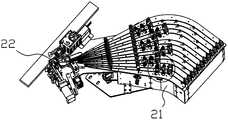
- Figure 2is a schematic diagram of the tape supply mechanism
- Figure 3is an enlarged view of area B in Figure 2;
- Figure 4is a schematic diagram of the tape feeding assembly
- Figure 5is a schematic diagram of the belt pressing mechanism
- Figure 6is a schematic diagram of the lifting mechanism for the tape supply
- Figure 7is a schematic diagram of a flush-cutting mechanism
- Figure 8is a partial structural diagram of the flush-cutting mechanism
- Figure 9is a schematic diagram of a first cutting mechanism
- Figure 10is an exploded schematic view of the first cutting mechanism
- Figure 11is a schematic diagram of the finishing mechanism
- Figure 12is a schematic diagram of the first finishing component
- Figure 13is an exploded schematic diagram of the first finishing component
- Figure 14is another exploded schematic view of the first finishing component
- Figure 15is a schematic diagram of a second finishing component
- Figure 16is an exploded schematic diagram of the second finishing component
- Figure 17is another exploded schematic view of the second finishing component
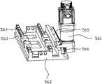
- Figure 18is a schematic diagram of a profile trimming mechanism
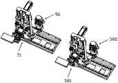
- Figure 19is a schematic diagram of a first profiling mechanism and a first profiling traverse mechanism
- Fig. 20is a schematic diagram of a first profiling traverse mechanism
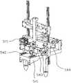
- Figure 21is a schematic diagram of a first profiling mechanism
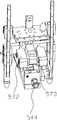
- Figure 22is another schematic diagram of the first profiling mechanism
- Figure 23is a schematic diagram of the profiling retracting drive mechanism
- Figure 24is another schematic diagram of the profiling retracting drive mechanism
- Figure 25is a schematic diagram of a profiling cutting mechanism
- Figure 26is a cross-sectional view of the profiling knife holder when the air duct is not inflated
- Figure 27is a cross-sectional view of the profiling knife holder when the air duct is inflated
- FIG. 28Schematic diagram of the finishing mechanism
- Figure 29is a schematic diagram of the first edge scraping assembly
- Figure 30is an exploded schematic view of the first scraping component
- Figure 31is another exploded schematic view of the first edge scraping assembly
- Figure 32is a schematic diagram of a second edge scraping assembly
- Figure 33is an exploded schematic view of the second scraping component
- Figure 34is another exploded schematic view of the second scraping assembly
- FIG. 35is a block diagram of the modules of the present invention.
- Fig. 36is a block diagram of a feed control unit, a separating agent control unit, and a CPU control unit. ;
- Figure 37is a block diagram of a conveying control unit, a beam pressing control unit, and a CPU control unit;
- Figure 38is a module block diagram of the tape feeding and cutting control unit, the tape feeding control unit, and the CPU control unit;
- Figure 39is a block diagram of the upper sol control unit, the lower sol control unit, the flat cutting control unit, and the CPU control unit;
- Figure 40is a block diagram of a rough repair control unit, a fine repair control unit, a profiling trimming control unit, and a CPU control unit;
- Fig. 41is a block diagram of a squeegee control unit, a broken wire control unit, a detergent control unit, a polishing control unit, and a CPU control unit.
- Tape supply mechanism-2tape supply rack-21, the first tape supply slot-211, the second tape supply slot-212,
- Belt pressing mechanism - 22belt pressing actuator - 221, belt pressing screw - 222, belt pressing nut - 223, bending plate - 224, iron plate - 225, belt pressing guide rod - 226 , Briquetting--227,
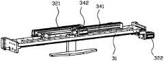
- Flat cutting head mechanism-3flat cutting fixing seat-31, flat cutting sliding rail-311, the first flat cutting buffer-312, the second flat cutting buffer-313,
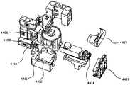
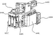
- Finishing mechanism-4finishing frame-41, first finishing buffer-421, second finishing buffer-422, first finishing component-43, first finishing horizontal movement Slider-4301, first finishing traverse nut-4302, first finishing traverse screw-4303, first finishing traverse actuator-4034, first finishing traverse frame-4035 , The first finishing lifting nut-4036, the first finishing lifting slider-4037, the first finishing lifting screw-4038, the first finishing lifting actuator-4039, the first finishing forward and retreating actuator --4310, the first finishing advance and retreat screw --4311, the first finishing advance and retreat nut --4312, the first finishing tool seat ---4313, the first finishing tool ---4314, the first finishing motor - 4315, Finishing the upper profile resisting wheel-4316, the third finishing cushion --4317, the first finishing side profile resisting wheel-4318, the first finishing dust cover-4319,
- Profile lifting drive mechanism--53profile lifting slide--531, profile lifting slider--532, profile lifting plate--533, profile lifting rack--534, profile lifting gear-- 535, profiling lifting motor-536, buffering part-537, buffer top block-538, buffer lifting plate-539, second buffer gas spring-530, copying knife drive mechanism-54, imitation Shaped retracting tool holder--541, profiled retracting slide rail--542, profiled retracting slider--543, profiled retracting cylinder--544,
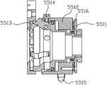
- Profile cutting mechanism--55profile knife holder--551, knife holder housing--5511, knife holder piston --5512, jaw --5513, jaw top post --5514, air duct --5515 , Elastic part--5516, profiled dust cover---5517, profiled cutter head assembly--552, profiled cutting motor--553,
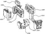
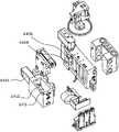
- Scraping mechanism-6scraping frame body-61, first scraping buffer-621, second scraping buffer-622, first scraping assembly-63, first scraping side traverse Slide block-6301, first scraping side traverse nut-6302, first scraping side traverse screw-6303, first scraping side traverse actuator-6304, first scraping side traverse frame-6305 ,
- a control system for an automatic edge banding machineis used for the automatic edge banding machine shown in Figures 1 to 38.
- the automatic edge banding machineincludes a conveying mechanism and a The tape cutting mechanism and the glue supply mechanism, the automatic edge banding machine also includes a tape supply mechanism 2, a flat cutting head mechanism 3, a finishing mechanism 4, a profiling and repairing mechanism, which are sequentially arranged around the conveying mechanism along the feeding direction of the conveying mechanism.
- the tape supply mechanism 2is used to transport the material tape from the external tape storage mechanism to the working area of the tape cutting mechanism and the glue supply mechanism;
- the flat cutting head drive mechanismis used to drive the flat cutting head mechanism 3.
- Flat cutting The aligning mechanism 3is used to cut the tape on the workpiece on the conveying mechanism;
- the finishing drive mechanismis used to drive the finishing mechanism 4, and the finishing mechanism 4 is used to cut an arc on the workpiece on the conveying mechanism;
- the profiling and trimming drive mechanismis used to drive the profiling and trimming mechanism 5, and the profiling and trimming mechanism 5 is used for profiling and trimming the workpiece located on the conveying mechanism;
- the scraping drive mechanismis used to drive the scraping
- the mechanism 6 and the scraping mechanism 6are used to align the arc edge of the workpiece on the conveying mechanism.
- the control systemincludes a CPU controller, a communication line connected to the CPU controller, a tape supply control unit connected to the communication line for one-way control, a flat cutting head control unit, a finishing control unit, and a profile trimming control unit And scraping control unit;
- the tape supply control unitis connected to the tape supply drive mechanism for one-way control
- the flat cutting head control unitis connected to the flat head drive mechanism for one-way control
- the finishing control unitis one-way controlled with the finishing drive mechanism.
- the edge trimming control unitis connected with the edge trimming drive mechanism in one-way control
- the edge scraping control unitis connected with the edge trimming drive mechanism in one-way control.
- the tape supply control unitincludes a tape supply I/O module, a tape supply driver, and a tape supply solenoid valve.
- the tape supply I/O moduleis connected to a communication line for unidirectional control, and the tape supply I/O module Connected to the one-way control of the tape supply solenoid valve, the tape supply driver is connected to the one-way control line of the communication line;
- the tape supply drive mechanismincludes a tape supply servo motor 231, a first tape supply cylinder 239, and a second tape supply cylinder 230
- the tape pressing actuator 221the tape supply servo motor 231 is connected to the tape supply drive for one-way control, the first tape supply cylinder 239 and the second tape supply cylinder 230 are both connected to the tape supply solenoid valve for one-way control, so
- the pressure belt actuator 221is connected to the communication line for one-way control.
- the flat cutting head control unitincludes a flat cutting position module, a flat cutting I/O module, a first flat cutting solenoid valve, a second flat cutting solenoid valve, and a flat cutting frequency converter.
- One-way control connection of the communication line, the flat-cutting I/O moduleis connected with the communication line and the flat-cutting position module one-way control, the first flat-cut solenoid valve, the second flat-cut solenoid valve and the flat-cut frequency converter are all connected with One-way control connection of the flat-cutting I/O module;
- the flat-cutting head drive mechanismincludes a first flat-cut linear cylinder 321, a first flat-cut acceleration cylinder 322, a first flat-cut pushing cylinder 334, and a first flat-cut y-axis Buffer cylinder 33213, first flat-cut x-axis buffer cylinder 33223, first flat-cut profile lift cylinder 3364, second flat-cut linear cylinder 341, second flat-cut acceleration cylinder 342, second flat-cut push cylinder
- the second flat-cut acceleration cylinder 342, the second flat-cut push cylinder, the second flat-cut y-axis buffer cylinder, the second flat-cut x-axis buffer cylinder, and the second flat-cut master lift cylinderare all connected to the second flat-cut electromagnetic
- the valveis connected in one-way control, and the first cutting device is connected in one-way control with the flat-cutting frequency converter.
- the finishing control unitincludes a finishing I/O module and a finishing inverter, the finishing I/O module is connected to a communication line for unidirectional control, and the finishing inverter is connected to the finishing I/O.
- the finishing drive mechanismincludes a first finishing traverse actuator 4034, a first finishing lifting actuator 4039, a first finishing advance and retreating actuator 4310, a first finishing motor 4315, and a second finishing motor.
- Finishing traverse actuator 4404, second finishing lifting actuator 4409, second finishing advance and retreating actuator 4410, and second finishing motor 4415, the first finishing traverse actuator 4034, first finishing lifting The actuator 4039, the first finishing retreat actuator 4310, the second finishing traverse actuator 4404, the second finishing lift actuator 4409, and the second finishing retraction actuator 4410are all connected to the communication line for unidirectional control.
- the first finishing motor 4315 and the second finishing motor 4415are both connected to the finishing inverter for unidirectional control;
- the profiling trimming control unitincludes a profiling I/O module, a profiling driver, a profiling solenoid valve, and a profiling frequency converter.
- the profiling I/O module and the profiling driverare all connected to a communication line.
- the profiling solenoid valve and profiling frequency converterare connected to the profiling I/O module for unidirectional control.
- the profiling trimming drive mechanismincludes profiling traverse motor 561, profiling lifting motor 536, The profiling retracting cylinder 544 and the profiling trimming motor, the profiling traverse motor 561 and the profiling lifting motor 536 are connected to the profiling drive for one-way control, and the profiling evacuation motor is connected to the profiling solenoid valve.
- the profiling cutting motor 553is connected to the profiling frequency converter for unidirectional control.
- the squeegee control unitincludes a squeegee I/O module and a squeegee solenoid valve
- the squeegee I/O moduleis connected to a communication line for one-way control
- the squeegee solenoid valveis connected to the squeegee I/O module for one-way control
- the scraper drive mechanismincludes a first scraper traverse actuator, a first scraper lift actuator, a first scraper advance and retreat actuator, a second scraper traverse actuator, a second scraper lift actuator, a second scraper advance and retreat actuator, and Scraper blowing device, the first scraper traverse actuator, the first scraper lift actuator, the first scraper advance and retreat actuator, the second scraper traverse actuator, the second scraper lift actuator, and the second scraper advance and retreat actuator They are all connected to the communication line for one-way control, and the scraper blowing device is connected to the scraper solenoid valve for one-way control.
- the edge banding machineis also equipped with materials such as a feeding control unit, a separating agent control unit, a conveying control unit, a beam control unit, and a cutting control unit.
- the large modulecan be designed as an open structure, which can be connected to the standardized interface and remote I/O on the CPU controller, and the hardware and The software is versatile and highly compatible.
- Each modulehas independent functions. Modules of the same type can be reused and interchanged in the product family. The permutation and combination of related modules can form the final product. Various functions can be selected. The combination and configuration of modules can create products with different needs, meet customer customization needs, and flexibly meet customer requirements for different configurations and market needs; the reuse of similarity can make the entire product purchase, manufacturing and maintenance more convenient .
- the communication lineis composed of four connection modes: PTO, RS485, CANopen, and I/O.
- Different types of componentssuch as position modules, I/O modules, actuators, and thermostats are connected to each other through different connection protocols.
- the CPU control unitrealizes one-way control connection, which has achieved different control effects.
- connection modeplease refer to Figure 39 to Figure 45, which will not be repeated here.
- the tape supply mechanism 2includes a tape supply frame 21, and the tape supply frame 21 is provided with a plurality of tape supply groups side by side, and the tape supply group is used for conveying at most two material tapes;
- a tape pressing mechanism 22is also provided at the end of the tape supply group, and the tape pressing mechanism 22 is used to resist the material tape located in the tape supply group.
- the tape supply setincludes a first tape supply groove 211 and a second tape supply groove 212 arranged at intervals, and a tape delivery assembly 23 located between the first tape supply groove 211 and the second tape supply groove 212.
- the tape feeding assembly 23is located between the first tape supply groove 211 and the second tape supply groove 212;
- the tape supply driving mechanismincludes a tape supply servo motor 231, a first tape supply cylinder 239, a second tape supply cylinder 230, and a belt press Actuator 221
- the belt delivery assembly 23includes a belt feeding drive wheel 232, a first belt feeding pressure wheel 233, a second belt feeding pressure wheel 234, a third belt feeding pressure wheel 235, a fourth belt feeding pressure wheel 236, and a A tape supply swing arm 237 and a second tape supply swing arm 238.
- the tape supply servo motor 231is installed at the tape supply frame 21, and the tape supply drive wheel 232 is installed at the output end of the tape supply servo motor 231.
- the belt feeding assembly 23is used to convey the material belt located on the first belt supply groove 211 to the end of the first belt supply groove 211 or used to convey the material belt located on the second belt supply groove 212 to the second belt supply groove The end of 212.
- the tape supply frame 21is fan-shaped, and the feeding ends of the first tape supply groove 211 and the second tape supply groove 212 are arranged in parallel, and gradually become narrower along the tape supply frame 21, so that the first tape supply groove 211 and the second tape supply groove 212 The ends of the first tape supply groove 211 and the second tape supply groove 212 are tightened to reduce the overall area of the tape supply frame 21.
- the end of the first tape supply cylinder 239 away from the output end, the end of the second tape supply cylinder 230 away from the output end, the first tape supply swing arm 237 and the second tape supply swing arm 238are all rotatably arranged on the tape supply frame. 21.
- the output end of the first tape supply cylinder 239is connected to the non-two ends of the first tape supply swing arm 237, and the output end of the second tape supply cylinder 230 is connected to the non-two ends of the second tape supply swing arm 238.
- the end positionsare connected, the first tape supply pressure roller 233 and the third tape supply pressure roller 235 are respectively provided at both ends of the first tape supply swing arm 237, the second tape supply pressure roller 234 and the fourth tape supply pressure roller
- the wheels 236are respectively provided at both ends of the second tape supply swing arm 238; the tape supply driving wheel 232 is located between the first tape supply groove 211 and the second tape supply groove 212, and the first tape supply pressure roller 233 and The third tape supply pressure roller 235 is located outside the first tape supply groove 211, and the second tape supply pressure roller 234 and the fourth tape supply pressure roller 236 are both located outside the second tape supply groove 212.
- the tape supply cylinder 239drives the first tape supply swing arm 237 to rotate so that the first tape supply pressure wheel 233 conflicts with or separates from the tape supply drive wheel 232, and the second tape supply cylinder 230 drives the second tape supply swing arm 238 to rotate so that The second tape supply pressing wheel 234 collides with or separates from the tape supply driving wheel 232.
- the tapeis fed into the tape from the feeding ends of the first tape supply groove 211 and the second tape supply groove 212 with the tape supply group as a unit, and the tape passes through the third tape supply groove 211 from the first tape supply groove 211.
- the first belt supply cylinder 239drives the first belt supply swing arm 237 to rotate, so that the first belt supply pressure wheel 233 interferes with the material tape and makes the material tape and the tape supply driving wheel 232 close, and then the tape supply servo motor 231 drives the tape supply driving wheel 232 to rotate, and completes the feeding of the first tape supply groove 211 under the action of friction.
- the feeding principle on the second feeding groove 212is the same as the feeding principle on the first feeding groove 211, which is composed of the belt driving pulley 232, the second belt pressure roller 234, and the fourth belt pressure roller 236.
- the second tape supply cylinder 230 and the second tape supply swing arm 238are completed in cooperation, except that the rotation direction of the tape supply servo motor 231 is opposite, which will not be repeated here. That is, in this embodiment, the rotation direction of the tape supply servo motor 231 and the activation of the first tape supply cylinder 239 or the second tape supply cylinder 230 can be switched at any time to complete the supply of the first tape supply groove 211 and the second tape supply groove 211 and the second tape supply cylinder 230.
- the free switching of the feeding belt on the belt groove 212, the operationis convenient and the control is precise.
- one-way bearingsare provided in the third tape supply pressure roller 235 and the fourth tape supply pressure roller 236 to prevent the material tape from retreating on the first tape supply groove 211 and the second tape supply groove 212.
- the belt pressing mechanism 22includes a belt pressing screw 222, a belt pressing nut 223, and a bending plate 224.
- the belt pressing actuator 221is provided on the belt supply frame 21, and the belt pressing actuator 221 is used for
- the belt screw 222is driven to drive the belt nut 223 to move up and down.
- the bending plate 224is arranged on one side of the belt nut 223; Located above the ends of the plurality of tape supply groups; the bending plate 224 is formed by bending a plurality of iron plates 225; the number of the pressing block 227 is two, and the two pressing blocks 227 are respectively set At both ends of the bent plate 224, two pressing blocks 227 are arranged front and back.
- the pressure belt actuator 221drives the pressure belt nut 223 to rise and fall, so that the material tape is always pressed by the block 227 during the tape feeding process. It is limited in the first tape supply groove 211 or the second tape supply groove 212 to avoid breakage or damage to the material tape due to separation.
- the tape supply frame 21is also vertically provided with a pressure belt guide rod 226, and the pressure belt nut 223 is slidably arranged on the belt-pressing guide rod 226 to ensure the smoothness and accuracy of the lifting and lowering of the belt-pressing nut 223; in addition, because the material belt is cut by the belt-cutting mechanism, it moves from the first belt-supply groove 211 and the second belt-supply groove 212 is separated, the front and rear pressure belts of the belt pressing mechanism 22 can be automatically adjusted up and down through the belt pressing actuator 221.
- This structurecombines the advantages of the previous structure in this embodiment, improves the efficiency of wood board edge sealing processing, and reduces labor , Cooperate with all parts of the edge banding machine to realize the full automation of the edge banding machine.
- the tape supply mechanism 2further includes a lifting mechanism, which is arranged below the tape supply frame 21 and is used to drive the tape supply frame 21 to lift.
- the lifting mechanismis composed of a conventional actuator, chain, sprocket, and screw. The actuator drives the screw up and down through the chain sprocket, which can be adjusted for different heights of edge banding, so that the band is neatly and without deviation. .
- the flat-cut aligning mechanism 3includes a flat-cut fixing seat 31, and a first flat-cutting mechanism 33 and a second flat-cutting mechanism 35 that are both slidably disposed on the flat-cut fixing seat 31.
- the flat-cut aligning mechanism 3The driving mechanism includes a first flat-cut translation mechanism 32, a second flat-cut translation mechanism 34, a first flat-cut y-axis buffer cylinder 33213, a first flat-cut x-axis buffer cylinder 33223, and a first flat-cut profile lift cylinder 3364.
- the first flat-cutting and translation mechanism 32includes a first flat-cutting linear cylinder 321 and a first flat-cutting acceleration cylinder 322.
- the first and second flat-cutting and translation mechanisms 32 and 34are both arranged on the flat-cutting fixing seat 31.
- the second translation mechanismincludes a second flat-cut linear cylinder 341 and a second flat-cut acceleration cylinder 342; the structure of the second flat-cutting mechanism 35 is mirror-symmetrical to the structure of the first flat-cutting mechanism 33, the The first flat cutting and translation mechanism 32 is used to drive the first flat cutting mechanism 33 to move transversely, the second flat cutting and translation mechanism 34 is used to drive the second flat cutting mechanism 35 to move horizontally;
- the first flat cutting mechanism 33includes a first flat cutting base 332, a first flat cutting rotating assembly 333, a first flat cutting pushing cylinder 334, a first flat cutting device 335, a first flat cutting slider 331, and a first flat cutting master mechanism 336,
- the flat cutting fixing seat 31is provided with a flat cutting sliding rail 311, the first flat cutting sliding block 331 is slidably disposed on the flat cutting sliding rail 311; the first flat cutting sliding block 331 is
- the cutting timeis shorter due to the small rotating stroke, which can greatly reduce the cutting time of the edge banding of the workpiece and increase the working efficiency of the edge banding machine.
- the first flat-cut acceleration cylinder 322is arranged at one end of the flat-cut fixing seat 31, the first flat-cut linear cylinder 321 is arranged at non-end positions of the flat-cut fixing seat 31, and the first flat cut
- the base 332is connected to the output end of the first flat-cut linear cylinder 321;
- the second flat-cut acceleration cylinder 342is arranged at the other end of the flat-cut fixing seat 31, and the second flat-cut linear cylinder 341 is arranged at the flat-cut fixing seat At the non-end positions of 31, the second base is connected to the output end of the second flat-cut linear cylinder 341.
- the output end of the first flat cutting acceleration cylinder 322directly hits the first flat cutting mechanism 33 to apply a lateral acceleration force to the first flat cutting mechanism 33 , So as to make the uniform translation of the first flat cutting mechanism 33 more stable.
- the first flat-cut base 332includes a first flat-cut y-axis buffer assembly 3321 and a first flat-cut x-axis buffer assembly 3322;
- the first flat-cut y-axis buffer assembly 3321includes a first flat-cut y-axis The slider 33211, the first flat-cut y-axis slide rail 33212, and the first flat-cut y-axis fixing plate 33214
- the first flat-cut x-axis buffer assembly 3322includes a first flat-cut x-axis slider 33221, a first flat-cut The x-axis sliding rail 33222 and the first flat-cut x-axis fixing plate 33224
- the first flat-cut sliding block 331is provided on one end surface of the first flat-cut y-axis fixing plate 33214
- the first flat-cut y-axis sliding rail 33212 and the first flat-cut y-axis buffer cylinder 33213are both provided on the other end surface of the first flat-cut y-axis fixing plate 33
- the flat-cut aligning mechanism 3further includes a first flat-cut profiling mechanism 336, and the first flat-cut profiling mechanism 336 includes a first flat-cut profiling bottom plate 3361, a first flat-cut profiling slider 3362.
- the mold lifting cylinder 3364is arranged on one side of the first flat-cutting profiling bottom plate 3361, and the first flat-cutting profiling slider 3362 is provided on the other end surface of the first flat-cutting profiling bottom plate 3361;
- the profiling slider 3362is slidably arranged on the first flat-cut profiling slide 3363, the first flat-cut profiling slide 3363 is provided on the first flat-cut profiling member 3365, and the first flat-cut profiling lifting cylinder
- the output end of the 3364is connected with
- the first flat-cut rotating assembly 333includes a first flat-cut rotating bottom plate 3331, a first flat-cut transverse adjustment seat 3332, and a first flat-cut rotating seat 3333.
- the horizontal adjustment seat 3332, the output end of the first flat cutting push cylinder 334is connected to the first flat cutting rotating seat 3333, and the first flat cutting device 335 is disposed on the first flat cutting rotating seat 3333; in this embodiment Among them, the first flat cutting device 335 is composed of a conventional saw blade and a motor.
- the position of the first flat cutting device 335can be adjusted; in addition, Since the weight of the first flat cutting device 335 is relatively large, the first flat cutting x-axis buffer assembly 3322 is arranged so that when the first flat cutting pushing cylinder 334 pulls the first flat cutting rotating assembly 333 back, the first flat cutting rotating assembly 333 can be adjusted.
- the flat-cutting device 335has a certain buffering effect to avoid damage to the components caused by inertia.
- the flat-cut limiting memberis provided with a first flat-cut inclined surface 361 for conflicting with the first flat-cut interference wheel 337; when the first flat-cut translation mechanism 32 drives the first flat-cut cutting mechanism 33 to move and causes the first flat-cut interference wheel to move
- the first flat-cut oblique surface 337is in contact with the first flat-cut oblique surface 361
- the first flat-cut interference wheel 337rolls along the first flat-cut oblique surface 361 and drives the first flat-cut rotating assembly 333 to rotate away from the first flat-cut cutting device 335.
- the flat-cut fixing seat 31is also provided with a first flat-cut buffer 312 at one end close to the first flat-cut cutting mechanism 33.
- the first flat-cut buffer 312is used to resist the first flat-cut base 332 and passes through the first flat-cut base 332.
- the flat cutting buffer 312acts on the first flat cutting mechanism 33 to increase the braking effect of the first flat cutting mechanism 33 during high-speed movement.
- the second flat-cutting mechanism 35 and the first flat-cutting mechanism 33are mirror-symmetrical, and the workpiece enters from the end of the flat-cut fixing seat 31 close to the first flat-cutting mechanism 33 to reach the working area of the present invention. , Then the first flat-cutting mechanism 33 and the second flat-cutting mechanism 35 move synchronously, and respectively cut the edge banding of the front and back of the workpiece, and the working principle of the second flat-cutting mechanism 35 is the same as that of the first flat-cutting mechanism.
- the working principle of the mechanism 33is basically the same, so I won't repeat it here.
- the second flat cutting buffer 313acts on the second flat cutting mechanism 35 to increase the second flat cutting mechanism 35 to move at a high speed.
- the second flat-cutting mechanism 35in the corresponding position of the second flat-cutting mechanism 35 is also provided with a second flat-second flat-cut resistance wheel 351, and the flat-cut stopper is also provided for the second flat-second flat-cut resistance.
- the second flat-cut inclined surface 362 that the wheel 351 conflicts, the direction of the second flat-cut inclined surface 362is opposite to the direction of the first flat-cut inclined surface 361, the second flat-second flat-cut interference wheel 351 matches the second flat-cut inclined surface 362 This allows the second flat cutting mechanism 35 to pass the physical limit at the beginning, to prevent the second flat cutting mechanism 35 from colliding with the workpiece when the workpiece moves to the corresponding position, and after the second flat cutting mechanism 35 moves, the second flat cutting mechanism 35 is moved
- the second flat cutting resistance wheel 351gradually departs from the second flat cutting
- the second flat-cut acceleration cylinder 342is arranged at the other end of the flat-cut fixing seat 31, the second flat-cut linear cylinder 341 is arranged at the non-end positions of the flat-cut fixing seat 31, and the second flat
- the tangent linear cylinder 341is connected to the output end of the second tangent linear cylinder 341.
- the second tangent acceleration cylinder 342has the same function as the first tangent acceleration cylinder 322.
- the second tangent linear cylinder 341has the same function as the first tangent acceleration cylinder.
- the function of the flat-cut linear cylinder 321is the same, and will not be repeated here.
- the finishing mechanism 4includes a finishing frame 41, a first finishing buffer 421, a second finishing buffer 422, and a first finishing assembly 43 and a first finishing assembly 43 and a second finishing assembly slidably disposed on the finishing frame 41.
- the second finishing assembly 44, the first finishing assembly 43is located above the second finishing assembly 44, the first finishing assembly 43 is used to cut an arc on one side of the upper end surface of the workpiece, and the first finishing assembly 43 is
- the trimming assembly 43is used to cut a circular arc on the same side of the lower end surface of the workpiece; the two ends of the first trimming buffer 421 are respectively connected to the first trimming assembly 43 and the lower end of the trimming frame 41.
- Two ends of the second finishing buffer member 422are respectively connected to the upper end of the second finishing assembly 44 and the finishing frame 41.
- the workpiecereaches the working area of the finishing mechanism 4 under the conveyance of the conveying mechanism.
- the first finishing assembly 43first contacts the upper side of the workpiece and continues to move on the workpiece.
- the first finishing component 43is used to cut an arc on one side of the upper end surface of the workpiece; then the workpiece continues to advance in the direction of the second finishing component 44 and contacts the second finishing component 44, and continues to move on the workpiece
- the second finishing component 44is used to cut a circular arc on one side of the lower end surface of the workpiece.
- the first finishing buffer 421 and the second finishing buffer 422are preferably gas springs.
- the first finishing assembly 43 and the second finishing assembly 44can finish the workpiece at the same time. Automatically adjust the workpiece at the same time to reduce errors.
- the finishing driving mechanismincludes a first finishing traverse actuator 4034, a first finishing lifting actuator 4039, a first finishing advance and retreating actuator 4310, and a first finishing motor 4315.
- the trimming assembly 43includes a first trimming traverse slider 4301, a first trimming traverse nut 4302, a first trimming traverse screw 4303, a first trimming traverse frame 4035, a first trimming lifting nut 4036, and a first trimming traverse nut 4302.
- a finishing traverse slider 4301is slidably arranged on the finishing frame 41, and one end of the first finishing buffer member 421 is connected to the first finishing traverse slider 4301; the first finishing traverse slider 4301 is slidably arranged in the first finishing traverse frame 4035, the first finishing traverse actuator 4034 is installed in the first finishing traverse frame 4035, and the first finishing traverse screw 4303 is specially arranged in the first finishing traverse frame 4035.
- the output end of a finishing traverse actuator 4034, the first finishing traverse nut 4302is screwed to the first finishing traverse screw 4303, and the first finishing traverse nut 4302 is connected to the first finishing traverse screw 4303.
- the sliding block 4301is linked; the first finishing lifting nut 4036 is slidably arranged on the first finishing traverse frame 4035, and the sliding direction of the first finishing lifting nut 4036 is the same as that of the first finishing traverse sliding block 4301
- the sliding directionsintersect perpendicularly, the first finishing lifting actuator 4039 is arranged on the first finishing traverse frame 4035, and the first finishing lifting screw 4038 is arranged on the output end of the first finishing lifting actuator 4039,
- the first finishing lifting nut 4036is screwed to the first finishing lifting screw 4038; the first finishing lifting slider 4037 is connected to the first finishing lifting nut 4036, and the first finishing advance and retreating actuator 4310 Set at the first finishing lifting slider 4037, the first finishing advance and retreat screw 4311 is installed at the output end
- the first finishing tool 4314is a pagoda multi-blade knife.
- the pagoda multi-blade knifeis placed horizontally.
- the first finishing tool 4314can be adjusted in three-axis direction. Precise adjustment to achieve the purpose of precise refinement.
- a plurality of finishing upper profile abutment wheels 4316extend outward from one side of the first finishing traverse frame 4035, and the plurality of finishing upper profile abutment wheels 4316 are horizontally arranged on one of the first finishing tools 4314.
- Side; a plurality of the finishing upper profile abutment wheel 4316 and the first finishing traverse frame 4035are provided with a third finishing buffer 4317; the lower end of the first finishing traverse frame 4035 extends outward
- the finishing actuators of this embodimentautomatically position the finishing upper profile abutment wheel 4316 and the first finishing side profile abutment wheel 4318, which can well control the tightness of the workpiece during finishing and further increase the finishing At the same time, it is buffered by the third finishing buffer 4317.
- the third finishing buffer 4317is preferably a spring.
- the first finishing tool holder 4313is also connected to a first finishing dust collecting cover 4319, the first finishing dust collecting cover 4319 is wrapped around the first finishing tool 4314, the first finishing dust collecting cover 4319 There is a first finishing opening (not shown in the figure) for revealing the first finishing tool 4314 at the lower end. Since the first finishing tool 4314 of this embodiment rotates counterclockwise, the slag of the workpiece trimming will fall on the right side of the knife. Therefore, the opening of the first finishing dust collecting cover 4319 of this embodiment is designed to face downwards. The direction of the dust suction opening of the finishing dust collecting hood 4319 follows the direction of the chip removal of the knife. At the same time, there is a sealing plate (not shown in the figure) to seal the gap of the first finishing motor 4315, and the suction power of the dust collection part is large and can be very good. To take away the crumbs.
- the finishing drive mechanismfurther includes a second finishing traverse actuator 4404, a second finishing lifting actuator 4409, a second finishing advance and retreat actuator 4410, and a second finishing motor 4415;
- the second finishing assembly 44includes the second finishing traverse slider 4401, the second finishing traverse nut 4402, the second finishing traverse screw 4403, the second finishing traverse frame 4405, the second finishing lifting nut 4406, the second finishing The repair lifting slider 4407, the second finishing lifting screw 4408, the second finishing advance and retreat screw 4411, the second finishing advance and retreat nut 4412, the second finishing tool seat 4413, and the second finishing tool 4414, the second finishing The trimming traverse slider 4401 is slidably arranged on the trimming frame 41, and one end of the second trimming buffer member 422 is connected to the second trimming traverse slider 4401; the second trimming traverse slider 4401 slides
- the second finishing traverse frame 4405is installed in the second finishing traverse frame 4405
- the second finishing traverse actuator 4404is installed in the second finishing traverse frame 4405
- the output end of the trimming traverse actuator 4404, the second trimming traverse nut 4402is screwed to the second trimming traverse screw 4403, the second trimming traverse nut 4402 and the second trimming traverse slide Block 4401 link;
- the second finishing lifting nut 4406is slidably arranged on the second finishing traverse frame 4405, the sliding direction of the second finishing lifting nut 4406 and the sliding direction of the second finishing traverse slider 4401 Vertically intersecting, the second finishing lifting actuator 4409 is installed on the second finishing traverse frame 4405, and the second finishing lifting screw 4408 is installed at the output end of the second finishing lifting actuator 4409.
- the second finishing lifting nut 4406is screwed to the second finishing lifting screw 4408; the second finishing lifting slider 4407 is connected to the second finishing lifting nut 4406, and the second finishing advance and retreating actuator 4410 is arranged at The second finishing lifting slider 4407, the second finishing advance and retreat screw 4411 is installed at the output end of the second finishing advance and retreat actuator 4410, and the second finishing advance and retreat nut 4412 is screwed to the second finishing advance and retreat Screw 4411, the second finishing tool holder 4413 is connected to the second finishing advance and retreat nut 4412; the second finishing motor 4415 is arranged on the second finishing tool holder 4413, and the second finishing tool 4414 is installed At the output end of the second finishing motor 4415.
- the second finishing tool 4414is a pagoda multi-blade knife.
- the pagoda multi-blade knifeis placed horizontally.
- the second finishing tool 4414can be adjusted in three-axis direction. Precise adjustment to achieve the purpose of precise refinement.
- One side of the second finishing traverse frame 4405extends outwardly with a plurality of finishing lower profiling wheels 4416, and the plurality of finishing lower profiling wheels 4416 are horizontally arranged on one of the second finishing tools 4414.
- Side; a plurality of the finishing lower profiling wheel 4416 and the second finishing traverse frame 4405are provided with a fourth finishing buffer 4417; the lower end of the second finishing traverse frame 4405 extends outward
- the actuators of this embodimentautomatically position and refine the lower profile abutment wheel 4416 and the second finish side profile abutment wheel 4418, which can well control the tightness of the workpiece during the finish, and further increase the precision of the finish Degree; at the same time by the fourth finishing buffer member 4417 for buffering, in this embodiment, the fourth finishing buffer member 4417 is preferably a spring.
- the second finishing tool holder 4413is also connected to a second finishing dust collecting cover 4419, the second finishing dust collecting cover 4419 is wrapped around the second finishing tool 4414, the second finishing dust collecting cover 4419 There is a second finishing opening (not shown in the figure) for revealing the second finishing tool 4414 at the upper end. Since the second finishing tool 4414 of this embodiment rotates counterclockwise, the slag from the trimming of the workpiece will fall to the right of the tool. Therefore, the opening of the second finishing dust collecting cover 4419 of this embodiment is designed to face upwards, The direction of the dust suction opening of the finishing dust collecting hood 4419 follows the direction of the chip removal of the knife. At the same time, there is a sealing plate (not shown in the figure) to seal the gap of the second finishing motor 4415. Good to get rid of the crumbs.
- the profiling and trimming mechanism 5includes a first profiling mechanism 51, and the first profiling mechanism 51 includes a profiling base 52 and a profiling trimming mechanism 5; the profiling and trimming driving mechanism includes a first profiling mechanism 51.
- the first profiling traverse drive mechanismis used to drive the first profiling mechanism 51 to traverse.
- the driving mechanism 53is used to drive the profiling and retracting drive mechanism 54 up and down.
- the profiling lifting and driving mechanism 53is provided on the profiling base 52.
- the profiling and retracting drive mechanism 54is used to drive the profiling and trimming mechanism 5 to move horizontally. .
- the profiling and trimming mechanism 5 of this embodimentautomatically performs profiling and trimming on the workpiece by setting the profiling lifting drive mechanism 53, the profiling retracting drive mechanism 54 and the profiling cutting mechanism 55, thereby automatically performing profiling and trimming on the workpiece, thereby the edge banding machine Improve the efficiency of profiling repair.
- the first profiling traverse mechanism 56includes a profiling traverse motor 561, a profiling traverse seat 562, a profiling traverse sliding block 563, a profiling traverse sliding rail 564, and a profiling traverse rack. 565 and the profiling traverse gear 566, the profiling traverse sliding rail 564 and profiling traverse rack 565 are all set on the profiling traverse seat 562, and the profiling traverse slider 563 is provided on the profiling base 52.
- the profiling traverse sliding block 563is slidably arranged on the profiling traverse sliding rail 564; the profiling traverse motor 561 is provided on the profiling base 52, and the profiling traverse gear 566 is installed on the profiling At the output end of the traverse motor 561, the profile traverse gear 566 meshes with the profile traverse rack 565.
- the profiling traverse motor 561is preferably a servo motor, and the profiling traverse rack 565 and the profiling traverse gear 566 are preferably helical gears. The precise control effect of the moving motor 561 on the lateral movement of the first profiling mechanism 51.
- the profiling base 52includes a profiling bottom plate 521, a first cushion gas spring 522, and a profiling frame 523 rotatably disposed on the profiling bottom plate 521.
- the profiling bottom plate 521is mounted on the first profiling traverse mechanism 56.
- the profiling lifting drive mechanism 53is provided on the profiling frame 523.
- one end of the first gas cushioning spring 522is rotatably arranged on one side of the profiling frame 523, and the other end of the first gas cushioning spring 522 is rotatably arranged on the simulation
- the profiled bottom plate 521is provided with the first cushioning gas spring 522, which can prevent the profiling frame 523 from rotating too fast and causing the components in the present invention to loosen;
- the profiled bottom plate 521is also provided with a top for resisting the profiling frame 523
- the placement direction of the rod 524 and the top rod 524are shown in FIGS.
- the profiling bottom plate 521is also provided with a top rod 524 for resisting the profiling frame 523 ,
- the placement direction of the top rod 524is shown in FIG. 25 and FIG. 26 to prevent the profiling frame 523 from rotating in the opposite direction.
- the profiling lifting drive mechanism 53includes a profiling lifting slide 531, a profiling lifting slider 532, a profiling lifting plate 533, a profiling lifting rack 534, a profiling lifting gear 535, and a profiling lifting motor 536.
- the profiling lifting slide 531 and the profiling elevator rack 534are all provided on the profiling base 52, and the profiling lifting slider 532, profiling knife retracting drive mechanism 54 and profiling lifting motor 536 are all provided on the profiling
- the lifting plate 533, the profile lifting slider 532is slidably arranged on the profile lifting slide 531; the profile lifting gear 535 is installed at the output end of the profile lifting motor 536, and the profile lifting gear 535 is connected to the profile lifting slide 531.
- the profiling elevator motor 536is preferably a servo motor, and the profiling elevating rack 534 and the profiling elevator gear 535 are preferably helical gears, through the cooperation of the above structure, to achieve Accurate control of the lifting movement of the first profiling mechanism 51.
- the profiling lifting plate 533is provided with a buffer portion 537, and the profiling base 52 is provided with a buffer top block 538 for resisting the buffer portion 537.
- the provision of the buffer portion 537 and the buffer top block 538can effectively avoid profiling
- the lifting driving mechanism 53is excessively lowered;
- the profiling elevating driving mechanism 53also includes a buffer lifting plate 539 and a second buffer gas spring 530.
- the buffer lifting plate 539is slidably disposed on the profiling base 52, and the second buffer gas spring One end of the 530 is connected to the buffer lifting plate 539, and the other end of the second buffer gas spring 530 is connected to the profiling lifting plate 533.
- the vertical second buffer gas spring 530 and the buffer lifting plate 539can effectively compensate The running difference between the profiling lifting drive mechanism 53 and the workpiece in the vertical direction.
- the profiling retraction drive mechanism 54includes a profiling evacuation frame 541, a profiling evacuation slide 542, a profiling evacuation slider 543, and a profiling evacuation cylinder 544.
- the profiling trimming mechanism 5, the profiling The output end of the contoured knife retracting cylinder 544 and the contoured knife retracting slide 542are both arranged on the contoured knife retracting frame 541, and the contoured knife retracting slider 543 and the contoured knife retracting cylinder 544 are both arranged on the contoured lifting drive mechanism. 53.
- the profiling knife retracting slider 543is slidably disposed on the profiling knife evacuation sliding rail 542.
- a horizontal buffer cylinder 571 parallel to the conveying direction of the workpieceis also provided.
- a horizontal buffer slide 572is provided with The horizontal buffer guide post 573 guides and limits the position, specifically: the horizontal buffer slider 572 is arranged between the profiling retracting drive mechanism 54 and the profiling lifting drive mechanism 53, and the horizontal buffer guide post 573 passes through the profiling lifting plate 533
- the sliding connection with the horizontal buffer slider 572can effectively compensate for the difference between the mechanism and the workpiece in the horizontal direction.
- the profiling and trimming mechanism 5includes a profiling knife base 551, a profiling knife head assembly 552, and a profiling trimming motor.
- the edge motoris arranged on the profiling knife base 551, and the profiling trimming motor is used to drive the profiling knife head assembly 552 to rotate; the profiling knife head assembly 552 is detachably mounted on the profiling knife base 551.
- the profiling knife holder 551includes a knife holder housing 5511 and a knife holder piston 5512 slidably disposed in the knife holder housing 5511.
- the output end of the profiling trimming motorpasses through one end of the knife holder housing 5511 and extends Into the tool holder housing 5511; one end of the tool holder housing 5511 close to the output end of the profiling trimming motor is rotatably provided with a plurality of claws 5513 for clamping the profiling cutter head assembly 552, the tool holder
- the side wall of the piston 5512 close to the claw 5513is provided with a plurality of claw studs 5514 corresponding to the claws 5513 one-to-one; a closed space is formed between the knife seat piston 5512 and the profiling knife seat 551, and the knife
- the seat piston 5512is provided with an air guide tube 5515 communicating with the enclosed space, the air guide tube 5515 is used to connect to an external air source, and an elastic member 5516 is also provided between the profiling knife seat 551 and the knife seat piston 5512
- the elastic member 5516is used to press the knife holder piston 5512 so that the claw top column 5514 abuts against the middle of the claw 5513
- Shaped cutter head assembly 552when the external air source vents into the enclosed space, the knife seat piston 5512 moves away from the claw 5513, and the claw top column 5514 abuts the end of the claw 5513 while driving the claw 5513 Rotate to loosen the profiling cutter head assembly 552; when the external air source vents into the enclosed space, the knife seat piston 5512 moves away from the claw 5513, and the claw top column 5514 abuts against the end of the claw 5513 At the same time, the claw 5513 is driven to rotate to loosen the profiling cutter head assembly 552, thereby facilitating the action of replacing the profiling cutter head assembly 552.
- the operation of quickly replacing the profiling cutter head assembly 552can be realized, so that when the profiling cutter head assembly 552 is to be replaced due to wear or change of the product to be processed, the profiling cutting mechanism 55 of this embodiment Can realize quick tool change.
- the elastic member 5516is preferably a spring.
- profiling cutter head assembly 552is also provided with a profiling dust collecting hood 5517, one end of the profiling dust collecting hood 5517 is in communication with the cutter head of the profiling cutter head assembly 552, the profiling dust collecting hood The other end of 5517 extends outwards, which can effectively collect dust caused by cutting workpieces and restrain the flying of dust.
- the first profiling mechanism 51can be driven twice to achieve profiling and trimming of the front and rear ends of the workpiece.
- a set of second profiling mechanism 581 similar in structure to the first profiling mechanism 51 and a second profiling traverse mechanism 582 that drives the second profiling mechanism 581 to moveif the cutter head of the first profiling mechanism 51 faces downward, Then the cutter head of the second profiling mechanism 581 faces upwards
- the workpieceenters the working area of the present invention from the previous station of the edge banding machine, and then the first profiling mechanism 51 follows the servo tracking trimming profiling disclosed in this embodiment.
- the machining method of the workpieceis to perform contour trimming on the upper front end and upper rear end of the workpiece; after the trimming of the first profiling mechanism 51 is completed, the second profiling mechanism 58181 refers to the servo tracking trimming disclosed in this embodiment.
- the contoured processing methodperforms contour trimming on the lower front end and lower rear end of the workpiece, thereby increasing the overall processing efficiency of the present invention.
- the scraping mechanism 6includes a scraping frame body 61, a first scraping buffer 621, a second scraping buffer 622, and a first scraping assembly 63 and a second scraping assembly slidably disposed on the scraping frame 61.
- Two scraping components 64, the first scraping component 63is located above the second scraping component 64, and the first scraping component 63 is used to scrape a circular arc edge on one side of the upper end surface of the workpiece.
- a scraping component 63is used to scrape a circular arc edge on the same side of the lower end surface of the workpiece; the two ends of the first scraping buffer 621 are respectively connected with the first scraping component 63 and the lower end of the scraping frame 61 , The two ends of the second scraping buffer 622 are respectively connected to the second scraping assembly 64 and the upper end of the scraping frame 61.
- the workpiecearrives at the working area of the present invention under the conveyance of the edge banding machine.
- the first edge scraping assembly 63first contacts the upper edge of one side of the workpiece and continues to move on the workpiece
- the first scraping component 63is used to scrape an arc edge on one side of the upper end surface of the workpiece; then the workpiece continues to advance in the direction of the second scraping component 64 and contacts the second scraping component 64, and is on the workpiece While continuing to move, the second edge scraping component 64 is used to scrape an arc edge on one side of the lower end surface of the workpiece.
- the first scraping buffer 621 and the second scraping buffer 622are preferably gas springs.
- the first scraping component 63 and the second scraping component 64 scrape the workpiecethey can be used at the same time. Automatically adjust the workpiece at the same time to reduce errors.
- the scraping drive mechanismincludes a first scraping traverse actuator 6304, a first scraping lifting actuator 6309, and a first scraping advance and retreat actuator 6310;
- the first scraping assembly 63includes a first scraping traverse Slider 6301, first scraping traverse nut 6302, first scraping traverse screw 6303, first scraping traverse frame 6305, first scraping lifting nut 6306, first scraping lifting slider 6307, first The scraping lifting screw 6308, the first scraping advance and retreat screw 6311, the first scraping advance and retreat nut 6312, the first scraping knife seat 6313, and the first scraping tool 6314, the first scraping traverse slider 6301 is slidably arranged In the scraping frame body 61, one end of the first scraping buffer 621 is connected to the first scraping traverse slider 6301; the first scraping traverse slider 6301 is slidably arranged at the first scraping traverse Frame 6305, the first scraping traverse actuator 6304 is installed on the first scraping
- the first scraping tool 6314is a pagoda multi-arc scraping knife.
- the pagoda multi-arc scraping knifeis placed horizontally, and the first scraping can be performed through the cooperation of the respective scraping actuators.
- the edge cutter 6314performs precise adjustment in three-axis directions to achieve the purpose of precise edge scraping.
- One side of the first scraping traverse frame 6305extends outwardly with a plurality of scraping upper mold abutment wheels 6316, and the plurality of scraping upper mold abutment wheels 6316 are arranged horizontally on one of the first scraping tools 6314.
- Side; a plurality of the scraping edge upper profile abutment wheel 6316 and the first scraping edge lateral movement frame 6305are provided with a third scraping edge buffer 6317; the lower end of the first scraping edge lateral movement frame 6305 extends outward
- Each scraping actuator of this embodimentautomatically locates the position of the scraping upper mold abutment wheel 6316 and the first scraping side mold abutment wheel 6318, which can well control the tightness of the workpiece during scraping and further increase the scraping.
- the third scraping buffer 6317is used for buffering.
- the third scraping buffer 6317is preferably a spring.
- the first scraping knife seat 6313is also connected to a first scraping dust collecting cover 6319, the first scraping dust collecting cover 6319 is wrapped around the first scraping knife 6314, the first scraping dust collecting cover 6319 There is a first scraping opening (not shown in the figure) for revealing the first scraping tool 6314 at the lower end. Since the first scraping tool 6314 of this embodiment scrapes the workpiece, the conveying direction of the scraping wire is opposite to that of the workpiece. Therefore, the opening of the first scraping dust collecting cover 6319 of this embodiment is designed to face downwards, and the first scraping edge set The direction of the suction port of the dust cover 6319 is opposite to the direction of the chip removal of the knife.
- the scraping drive mechanismalso includes a second scraping traverse actuator 6404, a second scraping lifting actuator 6409, and a second scraping advance and retreat actuator 6410;
- the second scraping assembly 64includes a second scraping horizontal Moving slider 6401, second scraping lateral movement nut 6402, second scraping lateral movement screw 6403, second scraping lateral movement frame 6405, second scraping lifting nut 6406, second scraping lifting slider 6407, first The second scraping lifting screw 6408, the second scraping advance and retreat screw 6411, the second scraping advance and retreat nut 6412, the second scraper seat 6413, the second scraper 6414, and the second scraper motor, the second scraper
- the traverse slider 6401is slidably arranged on the scraping frame 61, one end of the second scraping buffer 622 is connected to the second scraping traverse slider 6401; the second scraping traverse slider 6401 is slidably arranged In the second scraping side traverse frame 6405, the second scraping side traverse actuator 6404 is installed
- the second scraping lifting nut 6406is screwed to the second scraping lifting screw 6408; the second scraping lifting slider 6407 is connected to the second scraping lifting nut 6406, and the second scraping advance and retreat actuator 6410 is arranged in the first Two scraping lifting sliders 6407, the second scraping advance and retreat screw 6411 is installed at the output end of the second scraping advance and retreat actuator 6410, the second scraping advance and retreat nut 6412 is screwed to the second scraping advance and retreat screw 6411, the second scraper seat 6413 is connected to the second scraper advance and retreat nut 6412; the second scraper tool 6414 is provided at one end of the second scraper seat 6413.
- the second scraping tool 6414is a pagoda multi-arc scraping knife.
- the pagoda multi-arc scraping knifeis placed horizontally.
- the second scraping toolcan be The 6414 performs precise adjustment of the three-axis direction to achieve the purpose of precise scraping.
- a plurality of scraping lower profile abutment wheels 6416extend outward from one side of the second scraping lateral movement frame 6405, and the plurality of scraping lower profile abutment wheels 6416 are arranged horizontally on one of the second scraping tools 6414.
- Side; a plurality of the scraping edge lower profile abutment wheel 6416 and the second scraping edge lateral movement frame 6405are provided with a fourth scraping edge buffer 6417; the lower end of the second scraping edge lateral movement frame 6405 extends outward
- the actuators of this embodimentautomatically locate the lower profile abutment wheel 6416 for scraping and the position of the second profile abutment wheel 6418 on the side scraping side, which can well control the tightness of the workpiece during scraping and further increase the accuracy of scraping.
- the second edge scraping knife seat 6413is also connected to a second edge scraping contoured dust collecting cover 6419.
- the second edge scraping contoured dust collecting cover 6419is wrapped around the second edge scraping tool 6414.
- the upper end of the contoured dust collecting cover 6419is provided with a second scraping opening (not shown in the figure) for exposing the second scraping cutter 6414. Since the second scraping tool 6414 of this embodiment scrapes the workpiece, the conveying direction of the scraping wire is opposite to that of the workpiece.
- the opening of the second scraping profiling dust collecting cover 6419 of this embodimentis designed to face upwards, and the second scraping
- the direction of the suction port of the edge profiled dust collecting hood 6419is opposite to the direction of the chip removal of the knife, and the suction power of the suction part is large, and the debris can be well removed.
- the conveying mechanism, the tape cutting mechanism, and the glue supply mechanismare all existing technologies, and the edge banding machine is also provided with a feeding mechanism, a separating agent mechanism, a beam pressing mechanism, and a sol applying mechanism. , Dissolving mechanism, rough repair mechanism, broken wire mechanism, cleaning agent mechanism and polishing mechanism, that is, after the workpiece enters the edge banding machine from the feeding mechanism, it is transported by the conveying mechanism through the separating agent mechanism, the pressure beam mechanism, and the belt cutting mechanism.
- the workpieceAfter the mechanism, the upper sol mechanism, the lower sol mechanism, the flat cutting head mechanism, the rough trimming mechanism, the fine trimming mechanism, the profiling trimming mechanism, the scraping mechanism 6, the wire breaking mechanism, the cleaning agent mechanism and the polishing mechanism, the workpiece is unloaded Or transported to the next process; in view of the fact that the work between them does not affect each other, the location of the mechanism not described in this embodiment, the location of the edge banding machine and the working principle of the mechanism are all existing technologies, and will not be repeated here.
- the control system of an automatic edge banding machine of the present inventionhas the setting of the edge banding machine, the tape supply mechanism 2, the flat cutting head mechanism 3, the finishing mechanism 4, the contour trimming mechanism 5, and the edge scraping mechanism 6.
- the CPU controllercontrols the tape supply control unit and flat cutting head control unit , Finishing control unit, profile trimming control unit and edge scraping control unit control each drive mechanism to achieve the effect of increasing the efficiency of the edge banding machine.
Landscapes
- Life Sciences & Earth Sciences (AREA)
- Engineering & Computer Science (AREA)
- Manufacturing & Machinery (AREA)
- Wood Science & Technology (AREA)
- Forests & Forestry (AREA)
- Control Of Cutting Processes (AREA)
- Basic Packing Technique (AREA)
Abstract
Description
Translated fromChinese自动封边机为家具厂加工板材所用机械,各部件自动化程度高,目前市场上订制家具较多,每批订单内各种尺寸的板材都有,封边条颜色和封边条厚度都有差异,而市场上封边机绝大部分是普通型封边机,无法进行准确的控制,导致封边机封边效率受阻。The automatic edge banding machine is a machine used by furniture factories to process panels. Each component has a high degree of automation. At present, there are many custom-made furniture on the market. There are various sizes of panels in each batch of orders, and the edge bands are in color and thickness. However, most of the edge banding machines on the market are ordinary edge banding machines, which cannot be accurately controlled, which hinders the edge banding efficiency of the edge banding machine.
封边机是一种常见的木工机械,可以实现封边的机械化操作,其通过在边带上涂胶,然后将涂有胶水的边带胶黏在板材的侧边上。在贴边带的过程中,需要压带装置将边带按压,使得边带能够稳固的胶黏在板材的侧边上。但是现有的压带装置对不同板材的异型边缘压带时,需要手动调节压带件的压带角度或更换不同结构的压带件,调节或更换压带件不方便,增加了操作员的劳动强度。因此,缺陷十分明显,亟需提供一种解决方案。The edge banding machine is a common woodworking machine that can realize the mechanized operation of edge banding. It applies glue on the edge band, and then glues the glued edge band on the side of the board. During the welting process, a belt pressing device is required to press the side belt so that the side belt can be firmly glued to the side of the board. However, when the existing belt pressing device presses the special-shaped edges of different plates, it is necessary to manually adjust the belt pressing angle of the belt pressing parts or replace the belt pressing parts with different structures. It is inconvenient to adjust or replace the belt pressing parts, which increases the operator's Labor intensity. Therefore, the shortcomings are very obvious, and a solution is urgently needed.
发明内容Summary of the invention
根据本申请的各种实施例,提供一种自动封边机的控制系统。According to various embodiments of the present application, a control system of an automatic edge banding machine is provided.
一种自动封边机的控制系统,所述封边机包括输送机构、设于输送机构周围的切带机构以及供胶机构,其特征在于:所述自动封边机还包括沿着输送机构的送料方向依次设于输送机构周围的供带机构、平切齐头机构、精修机构、仿形修边机构、刮边机构、供带驱动机构、平切齐头驱动机构、精修驱动机构、仿形修边驱动机构以及刮边驱动机构;所述供带驱动机构用于驱 动供带机构,供带机构用于从外部的储带机构将料带输送至切带机构和供胶机构的工作区域;所述平切齐头驱动机构用于驱动平切齐头机构,平切齐头机构用于对位于输送机构上的工件进行切带;所述精修驱动机构用于驱动精修机构,精修机构用于对位于输送机构上的工件切割出圆弧;所述仿形修边驱动机构用于驱动仿形修边机构,仿形修边机构用于对位于输送机构上的工件仿形修边修边;所述刮边驱动机构用于驱动刮边机构,刮边机构用于对位于输送机构上的工件圆弧棱边;A control system for an automatic edge banding machine. The edge banding machine includes a conveying mechanism, a tape cutting mechanism and a glue supply mechanism arranged around the conveying mechanism. The feeding direction is arranged in sequence around the conveyor mechanism, the feeding mechanism, the flat cutting mechanism, the finishing mechanism, the profiling trimming mechanism, the scraping mechanism, the belt feeding driving mechanism, the flat cutting driving mechanism, the finishing driving mechanism, The profiling trimming drive mechanism and the scraping drive mechanism; the tape supply driving mechanism is used to drive the tape supply mechanism, and the tape supply mechanism is used to transport the material tape from the external tape storage mechanism to the tape cutting mechanism and the glue supply mechanism. Area; the flat-cutting head drive mechanism is used to drive the flat-cutting head mechanism, the flat-cutting head mechanism is used to cut the workpiece on the conveying mechanism; the finishing drive mechanism is used to drive the finishing mechanism, The finishing mechanism is used to cut a circular arc on the workpiece on the conveying mechanism; the profiling and trimming drive mechanism is used to drive the profiling and trimming mechanism, and the profiling and trimming mechanism is used to copy the workpiece on the conveying mechanism. Trimming; the scraping drive mechanism is used to drive the scraping mechanism, and the scraping mechanism is used to align the arc edge of the workpiece on the conveying mechanism;
所述控制系统包括CPU控制器、均与CPU控制器连接的通讯线、单向控制连接到通讯线的供带控制单元、平切齐头控制单元、精修控制单元、仿形修边控制单元以及刮边控制单元;The control system includes a CPU controller, a communication line connected to the CPU controller, a tape supply control unit connected to the communication line for one-way control, a flat cutting head control unit, a finishing control unit, and a profile trimming control unit And scraping control unit;
所述供带控制单元与供带驱动机构单向控制连接,所述平切齐头控制单元与平切齐头驱动机构单向控制连接,所述精修控制单元与精修驱动机构单向控制连接,所述仿形修边控制单元与仿形修边驱动机构单向控制连接,所述刮边控制单元与刮边驱动机构单向控制连接。The tape supply control unit is connected to the tape supply drive mechanism for one-way control, the flat cutting head control unit is connected to the flat head drive mechanism for one-way control, and the finishing control unit is one-way controlled with the finishing drive mechanism. The edge trimming control unit is connected with the edge trimming drive mechanism in one-way control, and the edge scraping control unit is connected with the edge trimming drive mechanism in one-way control.
本发明的一个或多个实施例的细节在下面的附图和描述中提出。本发明的其它特征、目的和优点将从说明书、附图以及权利要求书变得明显The details of one or more embodiments of the present invention are set forth in the following drawings and description. Other features, objects and advantages of the present invention will become apparent from the description, drawings and claims
图1为封边机的整体结构示意图;Figure 1 is a schematic diagram of the overall structure of the edge banding machine;
图2为供带机构的示意图;Figure 2 is a schematic diagram of the tape supply mechanism;
图3为图2中B区域的放大图;Figure 3 is an enlarged view of area B in Figure 2;
图4为送带组件的示意图;Figure 4 is a schematic diagram of the tape feeding assembly;
图5为压带机构的示意图;Figure 5 is a schematic diagram of the belt pressing mechanism;
图6为供带升降机构的示意图;Figure 6 is a schematic diagram of the lifting mechanism for the tape supply;
图7为平切齐头机构的示意图;Figure 7 is a schematic diagram of a flush-cutting mechanism;
图8为平切齐头机构的部分结构示意图;Figure 8 is a partial structural diagram of the flush-cutting mechanism;
图9为第一切割机构的示意图;Figure 9 is a schematic diagram of a first cutting mechanism;
图10为第一切割机构的分解示意图;Figure 10 is an exploded schematic view of the first cutting mechanism;
图11为精修机构的示意图;Figure 11 is a schematic diagram of the finishing mechanism;
图12为第一精修组件的示意图;Figure 12 is a schematic diagram of the first finishing component;
图13为第一精修组件的分解示意图;Figure 13 is an exploded schematic diagram of the first finishing component;
图14为第一精修组件的另一分解示意图;Figure 14 is another exploded schematic view of the first finishing component;
图15为第二精修组件的示意图;Figure 15 is a schematic diagram of a second finishing component;
图16为第二精修组件的分解示意图;Figure 16 is an exploded schematic diagram of the second finishing component;
图17为第二精修组件的另一分解示意图;Figure 17 is another exploded schematic view of the second finishing component;
图18为仿形修边机构的示意图;Figure 18 is a schematic diagram of a profile trimming mechanism;
图19为第一仿形机构以及第一仿形横移机构的示意图;Figure 19 is a schematic diagram of a first profiling mechanism and a first profiling traverse mechanism;
图20为第一仿形横移机构的示意图;Fig. 20 is a schematic diagram of a first profiling traverse mechanism;
图21为第一仿形机构的示意图;Figure 21 is a schematic diagram of a first profiling mechanism;
图22为第一仿形机构的另一示意图;Figure 22 is another schematic diagram of the first profiling mechanism;
图23为仿形退刀驱动机构的示意图;Figure 23 is a schematic diagram of the profiling retracting drive mechanism;
图24为仿形退刀驱动机构的另一示意图;Figure 24 is another schematic diagram of the profiling retracting drive mechanism;
图25为仿形切割机构的示意图;Figure 25 is a schematic diagram of a profiling cutting mechanism;
图26为导气管未充气时仿形刀座的剖视图;Figure 26 is a cross-sectional view of the profiling knife holder when the air duct is not inflated;
图27为导气管充气时仿形刀座的剖视图;Figure 27 is a cross-sectional view of the profiling knife holder when the air duct is inflated;
图28精修机构的示意图;Figure 28 Schematic diagram of the finishing mechanism;
图29为第一刮边组件的示意图;Figure 29 is a schematic diagram of the first edge scraping assembly;
图30为第一刮边组件的分解示意图;Figure 30 is an exploded schematic view of the first scraping component;
图31为第一刮边组件的另一分解示意图;Figure 31 is another exploded schematic view of the first edge scraping assembly;
图32为第二刮边组件的示意图;Figure 32 is a schematic diagram of a second edge scraping assembly;
图33为第二刮边组件的分解示意图;Figure 33 is an exploded schematic view of the second scraping component;
图34为第二刮边组件的另一分解示意图;Figure 34 is another exploded schematic view of the second scraping assembly;
图35为本发明的模块框图;Figure 35 is a block diagram of the modules of the present invention;
图36为进料控制单元、分离剂控制单元以及CPU控制单元的模块框图。;Fig. 36 is a block diagram of a feed control unit, a separating agent control unit, and a CPU control unit. ;
图37为输送控制单元、压梁控制单元以及CPU控制单元的模块框图;Figure 37 is a block diagram of a conveying control unit, a beam pressing control unit, and a CPU control unit;
图38为送带切带控制单元、供带控制单元以及CPU控制单元的模块框图;Figure 38 is a module block diagram of the tape feeding and cutting control unit, the tape feeding control unit, and the CPU control unit;
图39为上溶胶控制单元、下溶胶控制单元、平切控制单元以及CPU控制单元的模块框图;Figure 39 is a block diagram of the upper sol control unit, the lower sol control unit, the flat cutting control unit, and the CPU control unit;
图40为粗修控制单元、精修控制单元、仿形修边控制单元以及CPU控制单元的模块框图;Figure 40 is a block diagram of a rough repair control unit, a fine repair control unit, a profiling trimming control unit, and a CPU control unit;
图41为刮刀控制单元、断丝控制单元、清洁剂控制单元、抛光控制单元以及CPU控制单元的模块框图。Fig. 41 is a block diagram of a squeegee control unit, a broken wire control unit, a detergent control unit, a polishing control unit, and a CPU control unit.
附图标记Reference number
供带机构--2,供带机架--21,第一供带槽--211,第二供带槽--212,Tape supply mechanism-2, tape supply rack-21, the first tape supply slot-211, the second tape supply slot-212,
压带机构--22,压带执行器--221,压带螺杆--222,压带螺母--223,折弯板件--224,铁板--225,压带导杆--226,压块--227,Belt pressing mechanism - 22, belt pressing actuator - 221, belt pressing screw - 222, belt pressing nut - 223, bending plate - 224, iron plate - 225, belt pressing guide rod - 226 , Briquetting--227,
送带组件--23,供带伺服电机--231,供带主动轮--232,第一供带压轮--233,第二供带压轮--234,第三供带压轮--235,第四供带压轮--236,第一供带摆臂--237,第二供带摆臂--238,第一供带气缸--239,第二供带气缸--230,供带升降机构--24,Tape feeding component-23, tape supply servo motor-231, tape supply drive pulley-232, first supply pressure roller-233, second supply pressure roller-234, third supply pressure roller- -235, the fourth supply pressure roller--236, the first supply swing arm--237, the second supply swing arm--238, the first supply cylinder--239, the second supply cylinder--230 , For belt lifting mechanism-24,
平切齐头机构--3,平切固定座--31,平切滑轨--311,第一平切缓冲器--312,第二平切缓冲器--313,Flat cutting head mechanism-3, flat cutting fixing seat-31, flat cutting sliding rail-311, the first flat cutting buffer-312, the second flat cutting buffer-313,
第一平切平移机构--32,第一平切直线气缸--321,第一平切加速气缸--322,第一平切切割机构--33,第一平切滑块--331,The first flat cutting translation mechanism-32, the first flat cutting linear cylinder-321, the first flat cutting acceleration cylinder-322, the first flat cutting mechanism-33, the first flat cutting slider-331,
第一平切底座--332,第一平切y轴缓冲组件--3321,第一平切y轴滑块--33211,第一平切y轴滑轨--33212,第一平切y轴缓冲气缸--33213,第一平切y轴固定板--33214,第一平切x轴缓冲组件--3322,第一平切x轴滑块 --33221,第一平切x轴滑轨--33222,第一平切x轴缓冲气缸--33223,第一平切x轴固定板--33224,The first flat-cut base--332, the first flat-cut y-axis buffer component---3321, the first flat-cut y-axis slider--33211, the first flat-cut y-axis slide--33212, the first flat-cut y Shaft buffer cylinder--33213, first flat-cut y-axis fixed plate--33214, first flat-cut x-axis buffer assembly---3322, first flat-cut x-axis slider--33221, first flat-cut x-axis slide Rail--33222, the first flat-cut x-axis buffer cylinder--33223, the first flat-cut x-axis fixing plate--33224,
第一平切转动组件--333,第一平切转动底板--3331,第一平切横向调节座--3332,第一平切转动座--3333,The first flat-cut rotating component--333, the first flat-cut rotating bottom plate--3331, the first flat-cut horizontal adjustment seat--3332, the first flat-cut rotating seat---3333,
第一平切推动气缸--334,第一平切切割装置--335,The first flat cutting push cylinder--334, the first flat cutting device--335,
第一平切靠模机构--336,第一平切靠模底板--3361,第一平切靠模滑块--3362,第一平切靠模滑轨--3363,第一平切靠模升降气缸--3364,第一平切靠模压件--3365,第一平切抵触轮--337,The first flat cutting profiling mechanism-336, the first flat cutting profiling bottom plate-3361, the first flat cutting profiling slider-3362, the first flat cutting profiling slide-3363, the first flat cutting Profile lifting cylinder-3364, the first flat cutting profile part-3365, the first flat cutting interference wheel-337,
第二平切平移机构--34,第二平切直线气缸--341,第二平切加速气缸--342,第二平切切割机构--35,第二平第二平切抵触轮--351,The second flat cutting translation mechanism-34, the second flat cutting linear cylinder-341, the second flat cutting acceleration cylinder-342, the second flat cutting mechanism-35, the second flat second flat cutting interference wheel- -351,
平切平切限位件--36,第一平切斜面--361,第二平切斜面--362,Flat cut limit piece--36, the first flat cut inclined plane--361, the second flat cut inclined plane--362,
精修机构--4,精修架体--41,第一精修缓冲件--421,第二精修缓冲件--422,第一精修组件--43,第一精修横移滑块--4301,第一精修横移螺母--4302,第一精修横移螺杆--4303,第一精修横移执行器--4034,第一精修横移框架--4035,第一精修升降螺母--4036,第一精修升降滑块--4037,第一精修升降螺杆--4038,第一精修升降执行器--4039,第一精修进退执行器--4310,第一精修进退螺杆--4311,第一精修进退螺母--4312,第一精修刀座--4313,第一精修刀具--4314,第一精修电机--4315,精修上靠模抵触轮--4316,第三精修缓冲件--4317,第一精修侧靠模抵触轮--4318,第一精修集尘罩--4319,Finishing mechanism-4, finishing frame-41, first finishing buffer-421, second finishing buffer-422, first finishing component-43, first finishing horizontal movement Slider-4301, first finishing traverse nut-4302, first finishing traverse screw-4303, first finishing traverse actuator-4034, first finishing traverse frame-4035 , The first finishing lifting nut-4036, the first finishing lifting slider-4037, the first finishing lifting screw-4038, the first finishing lifting actuator-4039, the first finishing forward and retreating actuator --4310, the first finishing advance and retreat screw --4311, the first finishing advance and retreat nut --4312, the first finishing tool seat ---4313, the first finishing tool ---4314, the first finishing motor - 4315, Finishing the upper profile resisting wheel-4316, the third finishing cushion --4317, the first finishing side profile resisting wheel-4318, the first finishing dust cover-4319,
第二精修组件--44,第二精修横移滑块--4401,第二精修横移螺母--4402,第二精修横移螺杆--4403,第二精修横移执行器--4404,第二精修横移框架--4405,第二精修升降螺母--4406,第二精修升降滑块--4407,第二精修升降螺杆--4408,第二精修升降执行器--4409,第二精修进退执行器--4410,第二精修进退螺杆--4411,第二精修进退螺母--4412,第二精修刀座--4413,第二精修刀具--4414,第二精修电机--4415,精修下靠模抵触轮--4416,第四精修缓冲件--4417,第二精修侧靠模抵触轮--4418,第二精修集尘罩--4419, 仿形修边机构--5,第一仿形机构--51,仿形底座--52,仿形底板--521,第一缓冲气弹簧--522,仿形架--523,顶杆--524,The second finishing component-44, the second finishing traverse slider-4401, the second finishing traverse nut-4402, the second finishing traverse screw-4403, the second finishing traverse execution -4404, the second finishing traverse frame-4405, the second finishing lifting nut-4406, the second finishing lifting slider-4407, the second finishing lifting screw-4408, the second finishing Trimming lifting actuator-4409, second trimming forward and retreating actuator-4410, second trimming forward and retreating screw-4411, second trimming forward and retreating nut-4412, second trimming tool holder-4413, No. Second finishing tool-4414, second finishing motor-4415, finishing lower profiling wheel-4416, fourth finishing buffer-4417, second finishing side profiling wheel-4418 , The second finishing dust collecting cover-4419, the contour trimming mechanism-5, the first contouring mechanism-51, the contouring base-52, the contouring bottom plate-521, the first cushioning gas spring- -522, profile frame--523, ejector rod--524,
仿形升降驱动机构--53,仿形升降滑轨--531,仿形升降滑块--532,仿形升降板--533,仿形升降齿条--534,仿形升降齿轮--535,仿形升降电机--536,缓冲部--537,缓冲顶块--538,缓冲升降板--539,第二缓冲气弹簧--530,仿形退刀驱动机构--54,仿形退刀架--541,仿形退刀滑轨--542,仿形退刀滑块--543,仿形退刀气缸--544,Profile lifting drive mechanism--53, profile lifting slide--531, profile lifting slider--532, profile lifting plate--533, profile lifting rack--534, profile lifting gear-- 535, profiling lifting motor-536, buffering part-537, buffer top block-538, buffer lifting plate-539, second buffer gas spring-530, copying knife drive mechanism-54, imitation Shaped retracting tool holder--541, profiled retracting slide rail--542, profiled retracting slider--543, profiled retracting cylinder--544,
仿形切割机构--55,仿形刀座--551,刀座壳体--5511,刀座活塞--5512,卡爪--5513,卡爪顶柱--5514,导气管--5515,弹性件--5516,仿形集尘罩--5517,仿形刀头组件--552,仿形切割电机--553,Profile cutting mechanism--55, profile knife holder--551, knife holder housing--5511, knife holder piston --5512, jaw --5513, jaw top post --5514, air duct --5515 , Elastic part--5516, profiled dust cover---5517, profiled cutter head assembly--552, profiled cutting motor--553,
第一仿形横移机构--56,仿形横移电机--561,仿形横移座--562,仿形横移滑块--563,仿形横移滑轨--564,仿形横移齿条--565,仿形横移齿轮--566,水平缓冲气缸--571,水平缓冲滑块--572,水平缓冲导柱--573,第二仿形机构--581,第二仿形横移机构--582,The first profiling traverse mechanism--56, profiling traverse motor--561, profiling traverse seat--562, profiling traverse sliding block--563, profiling traverse sliding rail--564, imitation Shape traverse rack--565, profile traverse gear--566, horizontal cushion cylinder--571, horizontal cushion slider--572, horizontal cushion guide post--573, second profile mechanism--581, The second profiling traverse mechanism-582,
刮边机构--6,刮边架体--61,第一刮边缓冲件--621,第二刮边缓冲件--622,第一刮边组件--63,第一刮边横移滑块--6301,第一刮边横移螺母--6302,第一刮边横移螺杆--6303,第一刮边横移执行器--6304,第一刮边横移框架--6305,第一刮边升降螺母--6306,第一刮边升降滑块--6307,第一刮边升降螺杆--6308,第一刮边升降执行器--6309,第一刮边进退执行器--6310,第一刮边进退螺杆--6311,第一刮边进退螺母--6312,第一刮边刀座--6313,第一刮边刀具--6314,刮边上靠模抵触轮--6316,第三刮边缓冲件--6317,第一刮边侧靠模抵触轮--6318,第一刮边集尘罩--6319,Scraping mechanism-6, scraping frame body-61, first scraping buffer-621, second scraping buffer-622, first scraping assembly-63, first scraping side traverse Slide block-6301, first scraping side traverse nut-6302, first scraping side traverse screw-6303, first scraping side traverse actuator-6304, first scraping side traverse frame-6305 , The first scraping lifting nut-6306, the first scraping lifting slider-6307, the first scraping lifting screw-6308, the first scraping lifting actuator-6309, the first scraping advance and retreat actuator --6310, the first scraping edge advance and retreat screw-6311, the first scraping edge advance and retreat nut-6312, the first scraping knife seat-6313, the first scraping tool-6314, the scraping edge upper profile abutment wheel --6316, the third scraping buffer ---6317, the first scraping side profile abutment wheel ---6318, the first scraping dust cover ---6319,
第二刮边组件--64,第二刮边横移滑块--6401,第二刮边横移螺母--6402,第二刮边横移螺杆--6403,第二刮边横移执行器--6404,第二刮边横移框架--6405,第二刮边升降螺母--6406,第二刮边升降滑块--6407,第二刮边升降螺杆--6408,第二刮边升降执行器--6409,第二刮边进退执行器--6410, 第二刮边进退螺杆--6411,第二刮边进退螺母--6412,第二刮边刀座--6413,第二刮边刀具--6414,刮边下靠模抵触轮--6416,第四刮边缓冲件--6417,第二刮边侧靠模抵触轮--6418,第二刮边仿形集尘罩—6419。The second scraping component-64, the second scraping side traverse slider-6401, the second scraping side traverse nut-6402, the second scraping side traverse screw-6403, the second scraping side traverse execution Scraper-6404, second scraping side moving frame--6405, second scraping edge lifting nut--6406, second scraping edge lifting slider--6407, second scraping edge lifting screw--6408, second scraping Side lift actuator-6409, the second scraping edge forward and backward actuator-6410, the second scraping edge forward and retreat screw-6411, the second scraping edge forward and retreat nut-6412, the second scraping knife seat-6413, No. Second scraping tool--6414, scraping lower profiling wheel--6416, fourth scraping buffer--6417, second scraping side profiling wheel-6418, second scraping profiling dust collection Cover—6419.
为了便于理解本发明,下面将参照相关附图对本发明进行更全面的描述。附图中给出了本发明的较佳实施例。但是,本发明可以以许多不同的形式来实现,并不限于本文所描述的实施例。相反地,提供这些实施例的目的是使对本发明的公开内容的理解更加透彻全面。In order to facilitate the understanding of the present invention, the present invention will be described more fully below with reference to the relevant drawings. The preferred embodiments of the present invention are shown in the drawings. However, the present invention can be implemented in many different forms and is not limited to the embodiments described herein. On the contrary, the purpose of providing these embodiments is to make the understanding of the disclosure of the present invention more thorough and comprehensive.
需要说明的是,当元件被称为“固定于”另一个元件,它可以直接在另一个元件上或者也可以存在居中的元件。当一个元件被认为是“连接”另一个元件,它可以是直接连接到另一个元件或者可能同时存在居中元件。It should be noted that when an element is referred to as being "fixed to" another element, it can be directly on the other element or a central element may also be present. When an element is considered to be "connected" to another element, it can be directly connected to the other element or an intermediate element may be present at the same time.
除非另有定义,本文所使用的所有的技术和科学术语与属于本发明的技术领域的技术人员通常理解的含义相同。本文中在本发明的说明书中所使用的术语只是为了描述具体的实施例的目的,不是旨在于限制本发明。Unless otherwise defined, all technical and scientific terms used herein have the same meaning as commonly understood by those skilled in the technical field of the present invention. The terms used in the specification of the present invention herein are only for the purpose of describing specific embodiments, and are not intended to limit the present invention.
如图39至图45所示,一种自动封边机的控制系统,用于如图1至图38所示的自动封边机,该自动封边机包括输送机构、设于输送机构周围的切带机构以及供胶机构,所述自动封边机还包括沿着输送机构的送料方向依次设于输送机构周围的供带机构2、平切齐头机构3、精修机构4、仿形修边机构5、刮边机构6、供带驱动机构、平切齐头驱动机构、精修驱动机构、仿形修边驱动机构以及刮边驱动机构;所述供带驱动机构用于驱动供带机构2,供带机构2用于从外部的储带机构将料带输送至切带机构和供胶机构的工作区域;所述平切齐头驱动机构用于驱动平切齐头机构3,平切齐头机构3用于 对位于输送机构上的工件进行切带;所述精修驱动机构用于驱动精修机构4,精修机构4用于对位于输送机构上的工件切割出圆弧;所述仿形修边驱动机构用于驱动仿形修边机构5,仿形修边机构5用于对位于输送机构上的工件仿形修边修边;所述刮边驱动机构用于驱动刮边机构6,刮边机构6用于对位于输送机构上的工件圆弧棱边。As shown in Figure 39 to Figure 45, a control system for an automatic edge banding machine is used for the automatic edge banding machine shown in Figures 1 to 38. The automatic edge banding machine includes a conveying mechanism and a The tape cutting mechanism and the glue supply mechanism, the automatic edge banding machine also includes a tape supply mechanism 2, a flat
所述控制系统包括CPU控制器、均与CPU控制器连接的通讯线、单向控制连接到通讯线的供带控制单元、平切齐头控制单元、精修控制单元、仿形修边控制单元以及刮边控制单元;The control system includes a CPU controller, a communication line connected to the CPU controller, a tape supply control unit connected to the communication line for one-way control, a flat cutting head control unit, a finishing control unit, and a profile trimming control unit And scraping control unit;
所述供带控制单元与供带驱动机构单向控制连接,所述平切齐头控制单元与平切齐头驱动机构单向控制连接,所述精修控制单元与精修驱动机构单向控制连接,所述仿形修边控制单元与仿形修边驱动机构单向控制连接,所述刮边控制单元与刮边驱动机构单向控制连接。The tape supply control unit is connected to the tape supply drive mechanism for one-way control, the flat cutting head control unit is connected to the flat head drive mechanism for one-way control, and the finishing control unit is one-way controlled with the finishing drive mechanism. The edge trimming control unit is connected with the edge trimming drive mechanism in one-way control, and the edge scraping control unit is connected with the edge trimming drive mechanism in one-way control.
具体的,所述供带控制单元包括供带I/O模块、供带驱动器以及供带电磁阀,所述供带I/O模块与通讯线单向控制连接,所述供带I/O模块与供带电磁阀单向控制连接,所述供带驱动器与通讯线单向控线连接;所述供带驱动机构包括供带伺服电机231、第一供带气缸239、第二供带气缸230以及压带执行器221,所述供带伺服电机231与供带驱动器单向控制连接,所述第一供带气缸239和第二供带气缸230均与供带电磁阀单向控制连接,所述压带执行器221与通讯线单向控制连接。Specifically, the tape supply control unit includes a tape supply I/O module, a tape supply driver, and a tape supply solenoid valve. The tape supply I/O module is connected to a communication line for unidirectional control, and the tape supply I/O module Connected to the one-way control of the tape supply solenoid valve, the tape supply driver is connected to the one-way control line of the communication line; the tape supply drive mechanism includes a tape
具体的,所述平切齐头控制单元包括平切位置模块、平切I/O模块、第一平切电磁阀、第二平切电磁阀以及平切变频器,所述平切位置模块与通讯线单向控制连接,所述平切I/O模块与通讯线以及平切位置模块单向控制连 接,所述第一平切电磁阀、第二平切电磁阀以及平切变频器均与平切I/O模块单向控制连接;所述平切齐头驱动机构包括第一平切直线气缸321、第一平切加速气缸322、第一平切推动气缸334、第一平切y轴缓冲气缸33213、第一平切x轴缓冲气缸33223、第一平切靠模升降气缸3364、第二平切直线气缸341、第二平切加速气缸342、第二平切推动气缸、第二平切y轴缓冲气缸、第二平切x轴缓冲气缸以及第二平切靠模升降气缸,所述第一平切直线气缸321、第一平切加速气缸322、第一平切推动气缸334、第一平切y轴缓冲气缸33213、第一平切x轴缓冲气缸33223以及第一平切靠模升降气缸3364均与第一平切电磁阀单向控制连接,所述第二平切直线气缸341、第二平切加速气缸342、第二平切推动气缸、第二平切y轴缓冲气缸、第二平切x轴缓冲气缸以及第二平切靠模升降气缸均与第二平切电磁阀单向控制连接,所述第一切割装置与平切变频器单向控制连接。Specifically, the flat cutting head control unit includes a flat cutting position module, a flat cutting I/O module, a first flat cutting solenoid valve, a second flat cutting solenoid valve, and a flat cutting frequency converter. One-way control connection of the communication line, the flat-cutting I/O module is connected with the communication line and the flat-cutting position module one-way control, the first flat-cut solenoid valve, the second flat-cut solenoid valve and the flat-cut frequency converter are all connected with One-way control connection of the flat-cutting I/O module; the flat-cutting head drive mechanism includes a first flat-cut linear cylinder 321, a first flat-cut acceleration cylinder 322, a first flat-cut pushing cylinder 334, and a first flat-cut y-axis Buffer cylinder 33213, first flat-cut x-axis buffer cylinder 33223, first flat-cut profile lift cylinder 3364, second flat-cut linear cylinder 341, second flat-cut acceleration cylinder 342, second flat-cut push cylinder, second flat The first flat-cut linear cylinder 321, the first flat-cut acceleration cylinder 322, the first flat-cut push cylinder 334, the first flat-cut linear cylinder 321, the first flat-cut acceleration cylinder 322, and the first flat-cut linear cylinder The first flat-cut y-axis buffer cylinder 33213, the first flat-cut x-axis buffer cylinder 33223, and the first flat-cut profiling lifting cylinder 3364 are all connected to the first flat-cut solenoid valve for one-way control, and the second flat-cut linear cylinder 341. The second flat-
具体的,所述精修控制单元包括精修I/O模块以及精修变频器,所述精修I/O模块与通讯线单向控制连接,所述精修变频器与精修I/O模块单向控制连接,所述精修驱动机构包括第一精修横移执行器4034、第一精修升降执行器4039、第一精修进退执行器4310、第一精修电机4315、第二精修横移执行器4404、第二精修升降执行器4409、第二精修进退执行器4410以及第二精修电机4415,所述第一精修横移执行器4034、第一精修升降执行器4039、第一精修进退执行器4310、第二精修横移执行器4404、第二精修升降执行器4409以及第二精修进退执行器4410均与通讯线单向控制连接,所述第一精修电机4315和第二精修电机4415均与精修变频器单向控制连接;Specifically, the finishing control unit includes a finishing I/O module and a finishing inverter, the finishing I/O module is connected to a communication line for unidirectional control, and the finishing inverter is connected to the finishing I/O. One-way control connection of the module. The finishing drive mechanism includes a first finishing traverse actuator 4034, a first finishing lifting actuator 4039, a first finishing advance and retreating
具体的,所述仿形修边控制单元包括仿形I/O模块、仿形驱动器、仿形 电磁阀以及仿形变频器,所述仿形I/O模块和仿形驱动器均与通讯线单向控制连接,所述仿形电磁阀和仿形变频器均与仿形I/O模块单向控制连接,所述仿形修边驱动机构包括仿形横移电机561、仿形升降电机536、仿形退刀气缸544以及仿形修边电机,所述仿形横移电机561和仿形升降电机536均与仿形驱动器单向控制连接,所述仿形退刀电机与仿形电磁阀单向控制连接,所述仿形切割电机553与仿形变频器单向控制连接。Specifically, the profiling trimming control unit includes a profiling I/O module, a profiling driver, a profiling solenoid valve, and a profiling frequency converter. The profiling I/O module and the profiling driver are all connected to a communication line. The profiling solenoid valve and profiling frequency converter are connected to the profiling I/O module for unidirectional control. The profiling trimming drive mechanism includes
具体的,所述刮刀控制单元包括刮刀I/O模块以及刮刀电磁阀,所述刮刀I/O模块与通讯线单向控制连接,所述刮刀电磁阀与刮刀I/O模块单向控制连接,所述刮刀驱动机构包括第一刮刀横移执行器、第一刮刀升降执行器、第一刮刀进退执行器、第二刮刀横移执行器、第二刮刀升降执行器、第二刮刀进退执行器以及刮刀吹气装置,所述第一刮刀横移执行器、第一刮刀升降执行器、第一刮刀进退执行器、第二刮刀横移执行器、第二刮刀升降执行器以及第二刮刀进退执行器均与通讯线单向控制连接,所述刮刀吹气装置与刮刀电磁阀单向控制连接。Specifically, the squeegee control unit includes a squeegee I/O module and a squeegee solenoid valve, the squeegee I/O module is connected to a communication line for one-way control, and the squeegee solenoid valve is connected to the squeegee I/O module for one-way control, The scraper drive mechanism includes a first scraper traverse actuator, a first scraper lift actuator, a first scraper advance and retreat actuator, a second scraper traverse actuator, a second scraper lift actuator, a second scraper advance and retreat actuator, and Scraper blowing device, the first scraper traverse actuator, the first scraper lift actuator, the first scraper advance and retreat actuator, the second scraper traverse actuator, the second scraper lift actuator, and the second scraper advance and retreat actuator They are all connected to the communication line for one-way control, and the scraper blowing device is connected to the scraper solenoid valve for one-way control.
实际使用时,先将控制系统分成大模块,即供带控制单元、平切齐头控制单元、精修控制单元、仿形修边控制单元以及刮边控制单元等大模块,再将每个模块分成多个小的控制单元,需要说明的是,除了上述记载的个大模块,封边机还设置有诸如进料控制单元、分离剂控制单元、输送控制单元、压梁控制单元、切带控制单元、上溶胶控制单元、下溶胶控制单元、粗秀控制单元、断丝控制单元、清洁剂控制单元以及抛光控制单元等各大模块,由于这些模块的结构、设置方式以及运行方式均属于现有技术,具体可参考图39至图45或现有技术,在此不再赘述;另外,大模块可设计为开放式结构, 可与CPU控制器上的标准化接口和远程I/O连接,硬件和软件具有通用性,兼容性高,每一模块都是具有独立功能,相同种类的模块在产品族中可以重用和互换,相关模块的排列组合就可以形成最终的产品,通过选配各种功能模块的组合配置,就可以创建不同需求的产品,满足客户的定制需求,能灵活满足客户对不同配置的要求和市场的需求;相似性的重用,可以使整个产品采购、制造和维护上更加方便。In actual use, first divide the control system into large modules, that is, the tape supply control unit, the flat-cutting head control unit, the finishing control unit, the profiling trimming control unit, and the scraping control unit, etc., and then each module Divided into a number of small control units, it should be noted that in addition to the large modules described above, the edge banding machine is also equipped with materials such as a feeding control unit, a separating agent control unit, a conveying control unit, a beam control unit, and a cutting control unit. Unit, upper sol control unit, lower sol control unit, rough show control unit, broken wire control unit, detergent control unit, polishing control unit and other major modules, because the structure, setting mode and operation mode of these modules belong to the existing For details, please refer to Figure 39 to Figure 45 or the prior art, which will not be repeated here; in addition, the large module can be designed as an open structure, which can be connected to the standardized interface and remote I/O on the CPU controller, and the hardware and The software is versatile and highly compatible. Each module has independent functions. Modules of the same type can be reused and interchanged in the product family. The permutation and combination of related modules can form the final product. Various functions can be selected. The combination and configuration of modules can create products with different needs, meet customer customization needs, and flexibly meet customer requirements for different configurations and market needs; the reuse of similarity can make the entire product purchase, manufacturing and maintenance more convenient .
在本实施例中,通讯线由PTO、RS485、CANopen以及I/O四种连接方式构成,不同种类的部件诸如位置模块、I/O模块、执行器以及温控器分别通过不同的连接协议与CPU控制单元实现单向控制连接,已达到不同的控制效果,具体的连接方式可可参考图39至图45,在此不再赘述。In this embodiment, the communication line is composed of four connection modes: PTO, RS485, CANopen, and I/O. Different types of components such as position modules, I/O modules, actuators, and thermostats are connected to each other through different connection protocols. The CPU control unit realizes one-way control connection, which has achieved different control effects. For the specific connection mode, please refer to Figure 39 to Figure 45, which will not be repeated here.
具体的,所述供带机构2包括供带机架21,所述供带机架21并排设置有多组供带组,所述供带组用于输送至多两条料带;多个所述供带组的末端还设置有压带机构22,所述压带机构22用于抵触位于供带组的料带。Specifically, the tape supply mechanism 2 includes a
具体的,所述供带组包括间隔设置的第一供带槽211和第二供带槽212以及位于第一供带槽211和第二供带槽212之间的送带组件23,所述送带组件23位于第一供带槽211和第二供带槽212之间;所述供带驱动机构包括供带伺服电机231、第一供带气缸239、第二供带气缸230以及压带执行器221,所述送带组件23包括供带主动轮232、第一供带压轮233、第二供带压轮234、第三供带压轮235、第四供带压轮236、第一供带摆臂237以及第二供带摆臂238,所述供带伺服电机231设于供带机架21,所述供带主动轮232设于供带伺服电机231的输出端,所述送带组件23用于将位于第一供带槽211上的料带输送至第一供带槽211的末端或用于将位于第二供带槽212上的料带输 送至第二供带槽212的末端。Specifically, the tape supply set includes a first
在本实施例中,供带机架21呈扇形,第一供带槽211和第二供带槽212的进料端平行设置,并在沿着供带机架21逐渐变窄,从而使得第一供带槽211和第二供带槽212的末端收紧,减少供带机架21的整体占地面积。In this embodiment, the
具体的,所述第一供带气缸239远离输出端的一端、第二供带气缸230远离输出端的一端、第一供带摆臂237以及第二供带摆臂238均转动设置于供带机架21,所述第一供带气缸239的输出端与第一供带摆臂237的非两端位置连接,所述第二供带气缸230的输出端与第二供带摆臂238的非两端位置连接,所述第一供带压轮233和第三供带压轮235分别设于第一供带摆臂237的两端,所述第二供带压轮234以及第四供带压轮236分别设于第二供带摆臂238的两端;所述供带主动轮232位于第一供带槽211和第二供带槽212之间,所述第一供带压轮233和第三供带压轮235均位于第一供带槽211的外侧,所述第二供带压轮234和第四供带压轮236均位于第二供带槽212的外侧,所述第一供带气缸239驱动第一供带摆臂237转动以使得第一供带压轮233抵触或脱离供带主动轮232,所述第二供带气缸230驱动第二供带摆臂238转动以使得第二供带压轮234抵触或脱离供带主动轮232。Specifically, the end of the first
在实际使用时,以供带组为单位,从第一供带槽211和第二供带槽212的进料端分别送入料带,料带从第一供带槽211中经过第三供带压轮235后到达第一供带压轮233与供带主动轮232之间的位置,此时第一供带气缸239的驱动第一供带摆臂237转动,使得第一供带压轮233抵触于料带上并使得料带与供带主动轮232贴紧,随后供带伺服电机231驱动供带主动轮232转动,在摩擦力的作用下完成对第一供带槽211上的送带;同理,第二供带槽 212上的送带与第一供带槽211上的送带原理一致,由供带主动轮232、第二供带压轮234、第四供带压轮236、第二供带气缸230以及第二供带摆臂238配合完成,只是供带伺服电机231的转动方向相反,在此不再赘述。即在本实施例中,可通过随时切换供带伺服电机231的转动方向以及第一供带气缸239或第二供带气缸230的启动,即可完成对第一供带槽211和第二供带槽212上送带的自由切换,操作方便控制精准。In actual use, the tape is fed into the tape from the feeding ends of the first
具体的,所述第三供带压轮235内和第四供带压轮236内均设有单向轴承,以防止料带在第一供带槽211和第二供带槽212上倒退。Specifically, one-way bearings are provided in the third tape
具体的,所述压带机构22包括压带螺杆222、压带螺母223以及折弯板件224,所述压带执行器221设于供带机架21,所述压带执行器221用于驱动压带螺杆222带动压带螺母223升降,所述折弯板件224设于压带螺母223的一侧;所述折弯板件224设有若干压块227,若干所述压块227均位于多个所述供带组的末端的上方;所述折弯板件224由多根铁板225弯折加工而成;所述压块227的数量为两个,两个压块227分别设于折弯板件224的两端,两个压块227前后设置。料带在第一供带槽211和第二供带槽212上送带时,由压带执行器221驱动压带螺母223的升降,从而使得料带在送带过程中,始终被压块227限制于第一供带槽211或第二供带槽212内,避免发生脱离导致料带损坏或断裂。Specifically, the
具体的,为了避免压带螺母223在升降过程中偏移导致压块227未能压在料带上,所述供带机架21还竖直设置有压带导杆226,所述压带螺母223滑动设置于压带导杆226,以保证压带螺母223升降的平稳性和准确性;另外,由于料带在切带机构的切割下,从第一供带槽211和第二供带槽212上 分离,压带机构22的前后压带均可通过压带执行器221实现自动上下升降调节,此结构综合了本实施例中前面结构的优点,提高了木板封边加工效率,减少了劳动力,配合封边机各部装,实现了封边机的全自动化。Specifically, in order to avoid that the
具体的,所述供带机构2还包括升降机构,所述升降机构设于供带机架21的下方并用于驱动供带机架21升降。在本实施例中,升降机构由常规的执行器、链条、链轮以及螺杆组成,执行器通过链条链轮带动螺杆上下升降,可针对不同高度封边带进行调节,以便封带时整齐无偏差。Specifically, the tape supply mechanism 2 further includes a lifting mechanism, which is arranged below the
具体的,所述平切齐头机构3包括平切固定座31以及均滑动设置于平切固定座31的第一平切切割机构33和第二平切切割机构35,所述平切齐头驱动机构包括第一平切平移机构32、第二平切平移机构34、第一平切y轴缓冲气缸33213、第一平切x轴缓冲气缸33223以及第一平切靠模升降气缸3364,所述第一平切平移机构32包括第一平切直线气缸321以及第一平切加速气缸322,所述第一平切平移机构32和第二平切平移机构34均设置于平切固定座31,所述第二平移机构包括第二平切直线气缸341以及第二平切加速气缸342;所述第二平切切割机构35的结构与第一平切切割机构33的结构镜像对称,所述第一平切平移机构32用于驱动第一平切切割机构33横移,所述第二平切平移机构34用于驱动第二平切切割机构35横移;所述第一平切切割机构33包括第一平切底座332、第一平切转动组件333、第一平切推动气缸334、第一平切切割装置335、第一平切滑块331以及第一平切靠模机构336,所述平切固定座31设有平切滑轨311,所述第一平切滑块331滑动设置于平切滑轨311;所述第一平切滑块331设置于第一平切底座332的一端,所述第一平切靠模机构336设于第一平切底座332的一侧,所述第一平切靠模机构336 用于抵压工件;所述第一平切转动组件333转动设置于第一平切底座332的另一端,所述第一平切切割装置335装设于第一平切转动组件333,所述第一平切推动气缸334用于驱动第一平切转动组件333沿着第一平切底座332转动。Specifically, the flat-
本实施例的平切齐头机构3,由于转动的行程较小,故切割的时间较短,可极大减少对工件的封边带的切断时间,增加封边机切带的工作效率。In the flat-cutting and head-aligning
具体的,所述第一平切加速气缸322设于平切固定座31的一端,所述第一平切直线气缸321设于平切固定座31的非两端位置,所述第一平切底座332与第一平切直线气缸321的输出端连接;所述第二平切加速气缸342设于平切固定座31的另一端,所述第二平切直线气缸341设于平切固定座31的非两端位置,所述第二底座与第二平切直线气缸341的输出端连接。在封边机的传感器检测到工件移动至相应位置后,由第一平切加速气缸322的输出端直接撞击第一平切切割机构33,以对第一平切切割机构33施加一个横向加速力,以使得第一平切切割机构33的匀速平移更加稳定。Specifically, the first flat-
具体的,所述第一平切底座332包括第一平切y轴缓冲组件3321以及第一平切x轴缓冲组件3322;所述第一平切y轴缓冲组件3321包括第一平切y轴滑块33211、第一平切y轴滑轨33212以及第一平切y轴固定板33214,所述第一平切x轴缓冲组件3322包括第一平切x轴滑块33221、第一平切x轴滑轨33222以及第一平切x轴固定板33224,所述第一平切滑块331设于第一平切y轴固定板33214的一端面,所述第一平切y轴滑轨33212以及第一平切y轴缓冲气缸33213均设于第一平切y轴固定板33214的另一端面,所述第一平切y轴滑块33211设于第一平切x轴固定板33224的一端面,所述 第一平切y轴滑块33211滑动设置于第一平切y轴滑轨33212;所述第一平切x轴滑轨33222以及第一平切x轴缓冲气缸33223均设于第一平切x轴固定板33224的另一端面,所述第一平切x轴滑块33221设于第一平切转动组件333,所述第一平切x轴滑块33221滑动设置于第一平切x轴滑轨33222。Specifically, the first flat-cut base 332 includes a first flat-cut y-axis buffer assembly 3321 and a first flat-cut x-axis buffer assembly 3322; the first flat-cut y-axis buffer assembly 3321 includes a first flat-cut y-axis The slider 33211, the first flat-cut y-axis slide rail 33212, and the first flat-cut y-axis fixing plate 33214, the first flat-cut x-axis buffer assembly 3322 includes a first flat-cut x-axis slider 33221, a first flat-cut The x-axis sliding rail 33222 and the first flat-cut x-axis fixing plate 33224, the first flat-cut sliding block 331 is provided on one end surface of the first flat-cut y-axis fixing plate 33214, the first flat-cut y-axis sliding rail 33212 and the first flat-cut y-axis buffer cylinder 33213 are both provided on the other end surface of the first flat-cut y-axis fixing plate 33214, and the first flat-cut y-axis slider 33211 is provided on the first flat-cut x-axis fixing plate 33224 The first flat-cut y-axis slider 33211 is slidably disposed on the first flat-cut y-axis slide 33212; the first flat-cut x-axis slide 33222 and the first flat-cut x-axis buffer cylinder 33223 are both Set on the other end surface of the first flat-cut x-axis fixing plate 33224, the first flat-cut x-axis slider 33221 is provided on the first flat-cut rotating assembly 333, and the first flat-cut x-axis slider 33221 is slidably arranged In the first flat-cut x-axis slide rail 33222.
具体的,所述平切齐头机构3还包括第一平切靠模机构336,所述第一平切靠模机构336包括第一平切靠模底板3361、第一平切靠模滑块3362、第一平切靠模滑轨3363以及第一平切靠模压件3365,所述第一平切靠模底板3361的一端面设于第一平切底座332,所述第一平切靠模升降气缸3364设于第一平切靠模底板3361的一侧,所述第一平切靠模滑块3362设于第一平切靠模底板3361的另一端面;所述第一平切靠模滑块3362滑动设置于第一平切靠模滑轨3363,所述第一平切靠模滑轨3363设于第一平切靠模压件3365,所述第一平切靠模升降气缸3364的输出端与第一平切靠模压件3365连接。如图14所示,通过设置第一平切y轴缓冲组件3321,可很好地控制第一平切靠模机构336与工件之间的松紧度。Specifically, the flat-
具体的,所述第一平切转动组件333包括第一平切转动底板3331、第一平切横向调节座3332以及第一平切转动座3333,所述第一平切转动底板3331的一端面与第一平切底座332连接,所述第一平切横向调节座3332滑动设置于第一平切转动底板3331的另一端面;所述第一平切转动座3333转动设置于第一平切横向调节座3332,所述第一平切推动气缸334的输出端与第一平切转动座3333连接,所述第一平切切割装置335设置于第一平切转动座3333;在本实施例中,第一平切切割装置335由常规的切锯片和电机组合而成,通过调节第一平切横向调节座3332的位置,可对第一平切切割装置335的位置 进行调节;另外,由于第一平切切割装置335的重量较大,因此第一平切x轴缓冲组件3322的设置,在第一平切推动气缸334将第一平切转动组件333拉回时,可对第一平切切割装置335起到一定的缓冲作用,避免惯性对部件造成损坏。Specifically, the first flat-cut
所述第一平切转动组件333的一侧设有第一平切抵触轮337,所述平切固定座31靠近第一平切切割机构33的一侧设有平切限位件,所述平切限位件设有用于与第一平切抵触轮337抵触的第一平切斜面361;当第一平切平移机构32驱动第一平切切割机构33移动并使得第一平切抵触轮337抵触于第一平切斜面361时,第一平切抵触轮337沿着第一平切斜面361滚动并驱使第一平切转动组件333往远离第一平切切割装置335的方向转动。通过设置平切限位件,对第一平切切割机构33的移动进行强行移位,从而防止擦伤板料。One side of the first flat-cut
所述平切固定座31靠近第一平切切割机构33的一端还设有第一平切缓冲器312,所述第一平切缓冲器312用于抵触第一平切底座332,通过第一平切缓冲器312作用于第一平切切割机构33增加第一平切切割机构33在高速移动中的刹车效果。The flat-
在本实施例中,第二平切切割机构35与第一平切切割机构33镜像对称,工件从平切固定座31靠近第一平切切割机构33的一端进入从而到达本实用新型的工作区域,随后第一平切切割机构33和第二平切切割机构35同步移动,并分别对工件的前后的封边带进行切割,而第二平切切割机构35的工作原理与第一平切切割机构33的工作原理基本一致,在此不再赘述。同时,在平切固定座31的另一端还设有第二平切缓冲器313,通过第二平切缓冲器313 作用于第二平切切割机构35增加第二平切切割机构35在高速移动中的刹车效果;另外,在第二平切切割机构35的对应位置也设置有第二平第二平切抵触轮351,平切限位件上也设有用于第二平第二平切抵触轮351抵触的第二平切斜面362,第二平切斜面362的斜面方向与第一平切斜面361的方向相反,第二平第二平切抵触轮351与第二平切斜面362的配合使得第二平切切割机构35在一开始便通过物理限位,避免工件移动至相应位置时第二平切切割机构35与工件发生擦碰,并在第二平切切割机构35移动后由第二平第二平切抵触轮351逐渐脱离第二平切斜面362,随后即可正常对工件进行切割。In this embodiment, the second flat-cutting
具体的,所述第二平切加速气缸342设于平切固定座31的另一端,所述第二平切直线气缸341设于平切固定座31的非两端位置,所述第二平切直线气缸341与第二平切直线气缸341的输出端连接,第二平切加速气缸342的作用与第一平切加速气缸322的作用一致,第二平切直线气缸341的作用与第一平切直线气缸321的作用一致,在此不再赘述。Specifically, the second flat-
具体的,所述精修机构4包括精修架体41、第一精修缓冲件421、第二精修缓冲件422以及均滑动设置于精修架体41的第一精修组件43和第二精修组件44,所述第一精修组件43位于第二精修组件44的上方,所述第一精修组件43用于对工件上端面的一边切割出圆弧,所述第一精修组件43用于对工件下端面的同一边切割出圆弧;所述第一精修缓冲件421的两端分别与第一精修组件43以及精修架体41的下端连接,所述第二精修缓冲件422的两端分别与第二精修组件44以及精修架体41的上端连接。Specifically, the
实际使用时,工件在输送机构的输送下到达精修机构4的工作区域,假设工件从第一精修组件43进入,第一精修组件43首先与工件一边的上边接 触,并在工件持续移动的同时由第一精修组件43用于对工件上端面的一边切割出圆弧;随后工件继续往第二精修组件44的方向前进并与第二精修组件44接触,并在工件持续移动的同时由第二精修组件44用于对工件下端面的一边切割出圆弧。在本实施例中,第一精修缓冲件421和第二精修缓冲件422优选为气弹簧,在第一精修组件43和第二精修组件44对工件精修的同时,即可同时对工件同时进行自动调节,减少误差。In actual use, the workpiece reaches the working area of the
具体的,所述精修驱动机构包括第一精修横移执行器4034、第一精修升降执行器4039、第一精修进退执行器4310以及第一精修电机4315,所述第一精修组件43包括第一精修横移滑块4301、第一精修横移螺母4302、第一精修横移螺杆4303、第一精修横移框架4035、第一精修升降螺母4036、第一精修升降滑块4037、第一精修升降螺杆4038、第一精修进退螺杆4311、第一精修进退螺母4312、第一精修刀座4313以及第一精修刀具4314,所述第一精修横移滑块4301滑动设置于精修架体41,所述第一精修缓冲件421的一端与第一精修横移滑块4301连接;所述第一精修横移滑块4301滑动设置于第一精修横移框架4035,所述第一精修横移执行器4034装设于第一精修横移框架4035,所述第一精修横移螺杆4303专设于第一精修横移执行器4034的输出端,所述第一精修横移螺母4302螺接于第一精修横移螺杆4303,所述第一精修横移螺母4302与第一精修横移滑块4301链接;所述第一精修升降螺母4036滑动设置于第一精修横移框架4035,所述第一精修升降螺母4036的滑动方向与第一精修横移滑块4301的滑动方向垂直相交,所述第一精修升降执行器4039设于第一精修横移框架4035,所述第一精修升降螺杆4038装设于第一精修升降执行器4039的输出端,所述第一精修升降螺母4036 螺接于第一精修升降螺杆4038;所述第一精修升降滑块4037与第一精修升降螺母4036连接,所述第一精修进退执行器4310设于第一精修升降滑块4037,所述第一精修进退螺杆4311装设于第一精修进退执行器4310的输出端,所述第一精修进退螺母4312螺接于第一精修进退螺杆4311,所述第一精修刀座4313与第一精修进退螺母4312连接;所述第一精修电机4315设于第一精修刀座4313,所述第一精修刀具4314装设于第一精修电机4315的输出端。在本实施例中,所述第一精修刀具4314为宝塔多刃刀,该宝塔多刃刀水平放置,通过各个执行器的相互配合,即可对第一精修刀具4314进行三轴方向的精准调节,以达到精确精修的目的。Specifically, the finishing driving mechanism includes a first finishing traverse actuator 4034, a first finishing lifting actuator 4039, a first finishing advance and retreating
所述第一精修横移框架4035的一侧往外延伸有多个精修上靠模抵触轮4316,多个精修上靠模抵触轮4316均水平排布于第一精修刀具4314的一侧;多个所述精修上靠模抵触轮4316与第一精修横移框架4035之间均设有第三精修缓冲件4317;所述第一精修横移框架4035的下端往外延伸有第一精修侧靠模抵触轮4318,所述第一精修侧靠模抵触轮4318的一侧位于第一精修刀具4314的正下方。本实施例的各个精修执行器自动定位精修上靠模抵触轮4316以及第一精修侧靠模抵触轮4318位置,可很好地控制精修时工件的松紧度,进一步地增加精修的精确度;同时由第三精修缓冲件4317进行缓冲,在本实施例中,第三精修缓冲件4317优选为弹簧。A plurality of finishing upper
所述第一精修刀座4313还连接有第一精修集尘罩4319,所述第一精修集尘罩4319包裹于第一精修刀具4314,所述第一精修集尘罩4319的下端设有用于显露第一精修刀具4314的第一精修开口(图中未示出)。由于本实施例的第一精修刀具4314为逆时针旋转,工件修边的碎渣会摔在刀的右边,故 本实施例的第一精修集尘罩4319的开口设计朝下,第一精修集尘罩4319吸尘口的方向顺着刀的排屑方向,同时有密封板(图中未示出)封住第一精修电机4315的缺口,吸尘局部吸力大,能很好的把屑渣抽走。The first
所述精修驱动机构还包括第二精修横移执行器4404、第二精修升降执行器4409、第二精修进退执行器4410以及第二精修电机4415;所述第二精修组件44包括第二精修横移滑块4401、第二精修横移螺母4402、第二精修横移螺杆4403、第二精修横移框架4405、第二精修升降螺母4406、第二精修升降滑块4407、第二精修升降螺杆4408、第二精修进退螺杆4411、第二精修进退螺母4412、第二精修刀座4413以及第二精修刀具4414,所述第二精修横移滑块4401滑动设置于精修架体41,所述第二精修缓冲件422的一端与第二精修横移滑块4401连接;所述第二精修横移滑块4401滑动设置于第二精修横移框架4405,所述第二精修横移执行器4404装设于第二精修横移框架4405,所述第二精修横移螺杆4403专设于第二精修横移执行器4404的输出端,所述第二精修横移螺母4402螺接于第二精修横移螺杆4403,所述第二精修横移螺母4402与第二精修横移滑块4401链接;所述第二精修升降螺母4406滑动设置于第二精修横移框架4405,所述第二精修升降螺母4406的滑动方向与第二精修横移滑块4401的滑动方向垂直相交,所述第二精修升降执行器4409设于第二精修横移框架4405,所述第二精修升降螺杆4408装设于第二精修升降执行器4409的输出端,所述第二精修升降螺母4406螺接于第二精修升降螺杆4408;所述第二精修升降滑块4407与第二精修升降螺母4406连接,所述第二精修进退执行器4410设于第二精修升降滑块4407,所述第二精修进退螺杆4411装设于第二精修进退执行器4410的输出端,所 述第二精修进退螺母4412螺接于第二精修进退螺杆4411,所述第二精修刀座4413于第二精修进退螺母4412连接;所述第二精修电机4415设于第二精修刀座4413,所述第二精修刀具4414装设于第二精修电机4415的输出端。在本实施例中,所述第二精修刀具4414为宝塔多刃刀,该宝塔多刃刀水平放置,通过各个执行器的相互配合,即可对第二精修刀具4414进行三轴方向的精准调节,以达到精确精修的目的。The finishing drive mechanism further includes a second
所述第二精修横移框架4405的一侧往外延伸有多个精修下靠模抵触轮4416,多个精修下靠模抵触轮4416均水平排布于第二精修刀具4414的一侧;多个所述精修下靠模抵触轮4416与第二精修横移框架4405之间均设有第四精修缓冲件4417;所述第二精修横移框架4405的下端往外延伸有第二精修侧靠模抵触轮4418,所述第二精修侧靠模抵触轮4418的一侧位于第二精修刀具4414的正上方。本实施例的各个执行器自动定位精修下靠模抵触轮4416以及第二精修侧靠模抵触轮4418位置,可很好地控制精修时工件的松紧度,进一步地增加精修的精确度;同时由第四精修缓冲件4417进行缓冲,在本实施例中,第四精修缓冲件4417优选为弹簧。One side of the second
所述第二精修刀座4413还连接有第二精修集尘罩4419,所述第二精修集尘罩4419包裹于第二精修刀具4414,所述第二精修集尘罩4419的上端设有用于显露第二精修刀具4414的第二精修开口(图中未示出)。由于本实施例的第二精修刀具4414为逆时针旋转,工件修边的碎渣会摔在刀的右边,故本实施例的第二精修集尘罩4419的开口设计朝上,第二精修集尘罩4419的吸尘口的方向顺着刀的排屑方向,同时有密封板(图中未示出)封住第二精修电机4415的缺口,吸尘局部吸力大,能很好的把屑渣抽走。The second finishing tool holder 4413 is also connected to a second finishing
具体的,所述仿形修边机构5包括第一仿形机构51,所述第一仿形机构51包括仿形底座52以及仿形修边机构5;所述仿形修边驱动机构包括第一仿形横移机构56、仿形升降驱动机构53以及仿形退刀驱动机构54,所述第一仿形横移驱动机构用于驱动第一仿形机构51横移,所述仿形升降驱动机构53用于驱动仿形退刀驱动机构54升降,所述仿形升降驱动机构53设于仿形底座52,所述仿形退刀驱动机构54用于驱动仿形修边机构5横移。Specifically, the profiling and trimming mechanism 5 includes a
本实施例的仿形修边机构5,通过设置仿形升降驱动机构53、仿形退刀驱动机构54以及仿形切割机构55的设置,自动地对工件进行仿形修边,从而封边机提高仿形修补的效率。The profiling and trimming mechanism 5 of this embodiment automatically performs profiling and trimming on the workpiece by setting the profiling lifting
具体的,所述第一仿形横移机构56包括仿形横移电机561、仿形横移座562、仿形横移滑块563、仿形横移滑轨564、仿形横移齿条565以及仿形横移齿轮566,所述仿形横移滑轨564以及仿形横移齿条565均设于仿形横移座562,所述仿形横移滑块563设于仿形底座52,所述仿形横移滑块563滑动设置于仿形横移滑轨564;所述仿形横移电机561设于仿形底座52,所述仿形横移齿轮566装设于仿形横移电机561的输出端,所述仿形横移齿轮566与仿形横移齿条565啮合。在本实施例中,仿形横移电机561优选为伺服电机,而仿形横移齿条565以及仿形横移齿轮566优选为斜齿轮,通过上述结构的配合,以起到由仿形横移电机561对第一仿形机构51横向移动的精准控制效果。Specifically, the first
所述仿形底座52包括仿形底板521、第一缓冲气弹簧522以及转动设置于仿形底板521的仿形架523,仿形底板521装设于第一仿形横移机构56, 所述仿形升降驱动机构53设于仿形架523,通过设置可转动的仿形架523,当工作中出现异常时,例如工件即将撞上本发明时,可使仿形架523产生旋转而让工件通过,保护了本发明以及工件不会被撞坏;所述第一缓冲气弹簧522的一端转动设置于仿形架523的一侧,所述第一缓冲气弹簧522的另一端转动设置于仿形底板521,通过设置第一缓冲气弹簧522,可避免仿形架523的转动速度过快而导致本发明中的部件松动;所述仿形底板521还设有用于抵触仿形架523的顶杆524,顶杆524的放置方向如图4和图5所示,用于避免仿形架523进行相反方向的转动;所述仿形底板521还设有用于抵触仿形架523的顶杆524,顶杆524的放置方向如图25和图26所示,用于避免仿形架523进行相反方向的转动。The
所述仿形升降驱动机构53包括仿形升降滑轨531、仿形升降滑块532、仿形升降板533、仿形升降齿条534、仿形升降齿轮535以及仿形升降电机536,所述仿形升降滑轨531以及所述仿形升降齿条534均设于仿形底座52,所述仿形升降滑块532、仿形退刀驱动机构54以及仿形升降电机536均设于仿形升降板533,所述仿形升降滑块532滑动设置于仿形升降滑轨531;所述仿形升降齿轮535装设于仿形升降电机536的输出端,所述仿形升降齿轮535与仿形升降齿条534啮合;在本实施例中,仿形升降电机536优选为伺服电机,而仿形升降齿条534和仿形升降齿轮535优选为斜齿轮,通过上述结构的配合,以起到对第一仿形机构51升降移动的精准控制。The profiling lifting
所述仿形升降板533的一端设有缓冲部537,所述仿形底座52设有用于抵触缓冲部537的缓冲顶块538,缓冲部537和缓冲顶块538的设置可有效地避免仿形升降驱动机构53过度下降;所述仿形升降驱动机构53还包括缓 冲升降板539以及第二缓冲气弹簧530,所述缓冲升降板539滑动设置于仿形底座52,所述第二缓冲气弹簧530的一端连接于缓冲升降板539,所述第二缓冲气弹簧530的另一端连接于仿形升降板533,通过竖直方向设置的第二缓冲气弹簧530和缓冲升降板539,可以有效弥补仿形升降驱动机构53与工件竖直方向上的运行差异。One end of the
所述仿形退刀驱动机构54包括仿形退刀架541、仿形退刀滑轨542、仿形退刀滑块543以及仿形退刀气缸544,所述仿形修边机构5、仿形退刀气缸544的输出端以及仿形退刀滑轨542均设于仿形退刀架541,所述仿形退刀滑块543以及仿形退刀气缸544均设于仿形升降驱动机构53,所述仿形退刀滑块543滑动设置于仿形退刀滑轨542,通过设置仿形退刀气缸544,可快速地实行仿形切割机构55的进刀和退刀。The profiling
另外,除了竖直方向外,在仿形退刀驱动机构54与仿形升降驱动机构53之间,还设置有与工件的输送方向平行的水平缓冲气缸571,同时通过设置水平缓冲滑块572与水平缓冲导柱573进行导向与限位,具体为:水平缓冲滑块572设置于仿形退刀驱动机构54与仿形升降驱动机构53之间,水平缓冲导柱573穿过仿形升降板533与水平缓冲滑块572滑动连接,可有效弥补机构与工件水平方向上的运行差异。In addition, in addition to the vertical direction, between the profiling retracting
所述仿形修边机构5包括仿形刀座551、仿形刀头组件552以及仿形修边电机,所述仿形刀座551设于仿形退刀驱动机构54,所述仿形修边电机设于仿形刀座551,所述仿形修边电机用于驱动仿形刀头组件552转动;所述仿形刀头组件552可拆卸设置于仿形刀座551。所述仿形刀座551包括刀座壳体5511以及滑动设置于刀座壳体5511内的刀座活塞5512,所述仿形修边 电机的输出端穿过刀座壳体5511的一端并延伸至刀座壳体5511内;所述刀座壳体5511靠近仿形修边电机的输出端的一端面转动设置有多个用于夹持仿形刀头组件552的卡爪5513,所述刀座活塞5512靠近卡爪5513的侧壁设有多个与多个卡爪5513一一对应的卡爪顶柱5514;所述刀座活塞5512与仿形刀座551之间形成密闭空间,所述刀座活塞5512设有与所述密闭空间连通的导气管5515,所述导气管5515用于与外界的气源连接,所述仿形刀座551与刀座活塞5512之间还设有弹性件5516,所述弹性件5516用于抵压刀座活塞5512以使得卡爪顶柱5514抵触于卡爪5513的中部,所述弹性件5516还用于驱动多个卡爪5513转动并同时夹持于仿形刀头组件552;当外部的气源往所述密闭空间通气时,刀座活塞5512往远离卡爪5513的方向移动,卡爪顶柱5514抵触于卡爪5513的末端的同时驱动卡爪5513转动以松开仿形刀头组件552;当外部的气源往所述密闭空间通气时,刀座活塞5512往远离卡爪5513的方向移动,卡爪顶柱5514抵触于卡爪5513的末端的同时驱动卡爪5513转动以松开仿形刀头组件552,从而便于进行更换仿形刀头组件552的动作。通过本实施例的结构,可实现快速更换仿形刀头组件552的操作,使得当磨损或改变需加工的产品而导致要更换仿形刀头组件552时,本实施例的仿形切割机构55能实现快速换刀。在本实施例中,弹性件5516优选为弹簧。The profiling and trimming mechanism 5 includes a
所述仿形刀头组件552的一侧还设有仿形集尘罩5517,所述仿形集尘罩5517的一端与仿形刀头组件552的刀头连通,所述仿形集尘罩5517的另一端往外延伸,可有效地对切割工件造成的灰尘进行收集而抑制灰尘的飞扬。One side of the profiling
在本实施例中,可通过分别驱动第一仿形机构51两次,从而实现对工件 前后两端的仿形修边,但由于工件还存在另外两个角,故在本实施例中,通过增加一组与第一仿形机构51结构相似的第二仿形机构581以及驱动第二仿形机构581移动的第二仿形横移机构582(若第一仿形机构51的刀头朝下,则第二仿形机构581的刀头朝上),工件从封边机的上一工位进入本发明的工作区域,随后第一仿形机构51按照本实施例公开的伺服跟踪修边仿形的加工方法,对工件的上前端以及上后端进行仿形修边;待第一仿形机构51修边完成后,再由第二仿形机构58181参照本实施例公开的伺服跟踪修边仿形的加工方法,对工件的下前端以及下后端进行仿形修边,进而增加本发明整体的加工效率。In this embodiment, the
具体的,所述刮边机构6包括刮边架体61、第一刮边缓冲件621、第二刮边缓冲件622以及均滑动设置于刮边架体61的第一刮边组件63和第二刮边组件64,所述第一刮边组件63位于第二刮边组件64的上方,所述第一刮边组件63用于对工件上端面的一边刮出圆弧棱边,所述第一刮边组件63用于对工件下端面的同一边刮出圆弧棱边;所述第一刮边缓冲件621的两端分别与第一刮边组件63以及刮边架体61的下端连接,所述第二刮边缓冲件622的两端分别与第二刮边组件64以及刮边架体61的上端连接。Specifically, the
实际使用时,工件在封边机的输送下到达本实用新型的工作区域,假设工件从第一刮边组件63进入,第一刮边组件63首先与工件一边的上边接触,并在工件持续移动的同时由第一刮边组件63用于对工件上端面的一边刮出圆弧棱边;随后工件继续往第二刮边组件64的方向前进并与第二刮边组件64接触,并在工件持续移动的同时由第二刮边组件64用于对工件下端面的一边刮出圆弧棱边。在本实施例中,第一刮边缓冲件621和第二刮边缓冲件 622优选为气弹簧,在第一刮边组件63和第二刮边组件64对工件刮边的同时,即可同时对工件同时进行自动调节,减少误差。In actual use, the workpiece arrives at the working area of the present invention under the conveyance of the edge banding machine. Assuming that the workpiece enters from the first
所述刮边驱动机构包括第一刮边横移执行器6304、第一刮边升降执行器6309以及第一刮边进退执行器6310;所述第一刮边组件63包括第一刮边横移滑块6301、第一刮边横移螺母6302、第一刮边横移螺杆6303、第一刮边横移框架6305、第一刮边升降螺母6306、第一刮边升降滑块6307、第一刮边升降螺杆6308、第一刮边进退螺杆6311、第一刮边进退螺母6312、第一刮边刀座6313以及第一刮边刀具6314,所述第一刮边横移滑块6301滑动设置于刮边架体61,所述第一刮边缓冲件621的一端与第一刮边横移滑块6301连接;所述第一刮边横移滑块6301滑动设置于第一刮边横移框架6305,所述第一刮边横移执行器6304装设于第一刮边横移框架6305,所述第一刮边横移螺杆6303专设于第一刮边横移执行器6304的输出端,所述第一刮边横移螺母6302螺接于第一刮边横移螺杆6303,所述第一刮边横移螺母6302与第一刮边横移滑块6301链接;所述第一刮边升降螺母6306滑动设置于第一刮边横移框架6305,所述第一刮边升降螺母6306的滑动方向与第一刮边横移滑块6301的滑动方向垂直相交,所述第一刮边升降执行器6309设于第一刮边横移框架6305,所述第一刮边升降螺杆6308装设于第一刮边升降执行器6309的输出端,所述第一刮边升降螺母6306螺接于第一刮边升降螺杆6308;所述第一刮边升降滑块6307与第一刮边升降螺母6306连接,所述第一刮边进退执行器6310设于第一刮边升降滑块6307,所述第一刮边进退螺杆6311装设于第一刮边进退执行器6310的输出端,所述第一刮边进退螺母6312螺接于第一刮边进退螺杆6311,所述第一刮边刀座6313与第一刮边进退螺母 6312连接;所述第一刮边刀具6314设于第一刮边刀座6313的一端。在本实施例中,所述第一刮边刀具6314为宝塔多圆弧刮边刀,该宝塔多圆弧刮边刀水平放置,通过各个刮边执行器的相互配合,即可对第一刮边刀具6314进行三轴方向的精准调节,以达到精确刮边的目的。The scraping drive mechanism includes a first scraping traverse actuator 6304, a first scraping lifting actuator 6309, and a first scraping advance and retreat actuator 6310; the first scraping assembly 63 includes a first scraping traverse Slider 6301, first scraping traverse nut 6302, first scraping traverse screw 6303, first scraping traverse frame 6305, first scraping lifting nut 6306, first scraping lifting slider 6307, first The scraping lifting screw 6308, the first scraping advance and retreat screw 6311, the first scraping advance and retreat nut 6312, the first scraping knife seat 6313, and the first scraping tool 6314, the first scraping traverse slider 6301 is slidably arranged In the scraping frame body 61, one end of the first scraping buffer 621 is connected to the first scraping traverse slider 6301; the first scraping traverse slider 6301 is slidably arranged at the first scraping traverse Frame 6305, the first scraping traverse actuator 6304 is installed on the first scraping traverse frame 6305, and the first scraping traverse screw 6303 is specially arranged on the output of the first scraping traverse actuator 6304 End, the first scraping traverse nut 6302 is screwed to the first scraping traverse screw 6303, the first scraping traverse nut 6302 is linked with the first scraping traverse sliding block 6301; the first The scraping lifting nut 6306 is slidably arranged on the first scraping traverse frame 6305, the sliding direction of the first scraping lifting nut 6306 and the sliding direction of the first scraping traverse slider 6301 perpendicularly intersect, and the first scraping The side-lifting actuator 6309 is installed on the first scraping side traverse frame 6305, the first scraping-side lifting screw 6308 is installed at the output end of the first scraping-side lifting actuator 6309, and the first scraping-side lifting nut 6306 is screwed Connected to the first scraping lifting screw 6308; the first scraping lifting slider 6307 is connected to the first scraping lifting nut 6306, and the first scraping advance and retreat actuator 6310 is provided on the first scraping lifting slider 6307 , The first scraping advance and retreat screw 6311 is installed at the output end of the first scraping advance and retreat actuator 6310, the first scraping advance and retreat nut 6312 is screwed to the first scraping advance and retreat screw 6311, the first scraping The edge cutter seat 6313 is connected with the first edge scraping advance and retreat nut 6312; the first edge scraper 6314 is arranged at one end of the first edge scraper base 6313. In this embodiment, the
所述第一刮边横移框架6305的一侧往外延伸有多个刮边上靠模抵触轮6316,多个刮边上靠模抵触轮6316均水平排布于第一刮边刀具6314的一侧;多个所述刮边上靠模抵触轮6316与第一刮边横移框架6305之间均设有第三刮边缓冲件6317;所述第一刮边横移框架6305的下端往外延伸有第一刮边侧靠模抵触轮6318,所述第一刮边侧靠模抵触轮6318的一侧位于第一刮边刀具6314的正下方。本实施例的各个刮边执行器自动定位刮边上靠模抵触轮6316以及第一刮边侧靠模抵触轮6318位置,可很好地控制刮边时工件的松紧度,进一步地增加刮边的精确度;同时由第三刮边缓冲件6317进行缓冲,在本实施例中,第三刮边缓冲件6317优选为弹簧。One side of the first
所述第一刮边刀座6313还连接有第一刮边集尘罩6319,所述第一刮边集尘罩6319包裹于第一刮边刀具6314,所述第一刮边集尘罩6319的下端设有用于显露第一刮边刀具6314的第一刮边开口(图中未示出)。由于本实施例的第一刮边刀具6314对工件刮边后,刮丝与工件的输送方向相反,故本实施例的第一刮边集尘罩6319的开口设计朝下,第一刮边集尘罩6319吸尘口的方向逆着刀的排屑方向,吸尘局部吸力大,能很好的把屑渣抽走。The first
所述刮边驱动机构还包括第二刮边横移执行器6404、第二刮边升降执行器6409以及第二刮边进退执行器6410;所述第二刮边组件64包括第二刮边横移滑块6401、第二刮边横移螺母6402、第二刮边横移螺杆6403、第二刮 边横移框架6405、第二刮边升降螺母6406、第二刮边升降滑块6407、第二刮边升降螺杆6408、第二刮边进退螺杆6411、第二刮边进退螺母6412、第二刮边刀座6413、第二刮边刀具6414以及第二刮边电机,所述第二刮边横移滑块6401滑动设置于刮边架体61,所述第二刮边缓冲件622的一端与第二刮边横移滑块6401连接;所述第二刮边横移滑块6401滑动设置于第二刮边横移框架6405,所述第二刮边横移执行器6404装设于第二刮边横移框架6405,所述第二刮边横移螺杆6403专设于第二刮边横移执行器6404的输出端,所述第二刮边横移螺母6402螺接于第二刮边横移螺杆6403,所述第二刮边横移螺母6402与第二刮边横移滑块6401链接;所述第二刮边升降螺母6406滑动设置于第二刮边横移框架6405,所述第二刮边升降螺母6406的滑动方向与第二刮边横移滑块6401的滑动方向垂直相交,所述第二刮边升降执行器6409设于第二刮边横移框架6405,所述第二刮边升降螺杆6408装设于第二刮边升降执行器6409的输出端,所述第二刮边升降螺母6406螺接于第二刮边升降螺杆6408;所述第二刮边升降滑块6407与第二刮边升降螺母6406连接,所述第二刮边进退执行器6410设于第二刮边升降滑块6407,所述第二刮边进退螺杆6411装设于第二刮边进退执行器6410的输出端,所述第二刮边进退螺母6412螺接于第二刮边进退螺杆6411,所述第二刮边刀座6413于第二刮边进退螺母6412连接;所述第二刮边刀具6414设于第二刮边刀座6413的一端。在本实施例中,所述第二刮边刀具6414为宝塔多圆弧刮边刀,该宝塔多圆弧刮边刀水平放置,通过各个执行器的相互配合,即可对第二刮边刀具6414进行三轴方向的精准调节,以达到精确刮边的目的。The scraping drive mechanism also includes a second scraping traverse actuator 6404, a second scraping lifting actuator 6409, and a second scraping advance and retreat actuator 6410; the second scraping assembly 64 includes a second scraping horizontal Moving slider 6401, second scraping lateral movement nut 6402, second scraping lateral movement screw 6403, second scraping lateral movement frame 6405, second scraping lifting nut 6406, second scraping lifting slider 6407, first The second scraping lifting screw 6408, the second scraping advance and retreat screw 6411, the second scraping advance and retreat nut 6412, the second scraper seat 6413, the second scraper 6414, and the second scraper motor, the second scraper The traverse slider 6401 is slidably arranged on the scraping frame 61, one end of the second scraping buffer 622 is connected to the second scraping traverse slider 6401; the second scraping traverse slider 6401 is slidably arranged In the second scraping side traverse frame 6405, the second scraping side traverse actuator 6404 is installed on the second scraping side traverse frame 6405, and the second scraping side traverse screw 6403 is specially arranged on the second scraping side The output end of the traverse actuator 6404, the second scraping traverse nut 6402 is screwed to the second scraping traverse screw 6403, the second scraping traverse nut 6402 and the second scraping traverse slider 6401 link; the second edge scraping lifting nut 6406 is slidably arranged on the second edge scraping traverse frame 6405, and the sliding direction of the second edge scraping lifting nut 6406 is perpendicular to the sliding direction of the second edge scraping traverse slider 6401 The second edge scraping lifting actuator 6409 is arranged on the second edge scraping transverse movement frame 6405, and the second edge scraping lifting screw 6408 is installed at the output end of the second edge scraping lifting actuator 6409. The second
所述第二刮边横移框架6405的一侧往外延伸有多个刮边下靠模抵触轮 6416,多个刮边下靠模抵触轮6416均水平排布于第二刮边刀具6414的一侧;多个所述刮边下靠模抵触轮6416与第二刮边横移框架6405之间均设有第四刮边缓冲件6417;所述第二刮边横移框架6405的下端往外延伸有第二刮边侧靠模抵触轮6418,所述第二刮边侧靠模抵触轮6418的一侧位于第二刮边刀具6414的正上方。本实施例的各个执行器自动定位刮边下靠模抵触轮6416以及第二刮边侧靠模抵触轮6418位置,可很好地控制刮边时工件的松紧度,进一步地增加刮边的精确度;同时由第四刮边缓冲件6417进行缓冲,在本实施例中,第四刮边缓冲件6417优选为弹簧。A plurality of scraping lower
所述第二刮边刀座6413还连接有第二刮边仿形集尘罩6419,所述第二刮边仿形集尘罩6419包裹于第二刮边刀具6414,所述第二刮边仿形集尘罩6419的上端设有用于显露第二刮边刀具6414的第二刮边开口(图中未示出)。由于本实施例的第二刮边刀具6414对工件刮边后,刮丝与工件的输送方向相反,故本实施例的第二刮边仿形集尘罩6419的开口设计朝上,第二刮边仿形集尘罩6419的吸尘口的方向逆着刀的排屑方向,吸尘局部吸力大,能很好的把屑渣抽走。The second edge scraping knife seat 6413 is also connected to a second edge scraping contoured dust collecting cover 6419. The second edge scraping contoured dust collecting cover 6419 is wrapped around the second edge scraping tool 6414. The upper end of the contoured dust collecting cover 6419 is provided with a second scraping opening (not shown in the figure) for exposing the second scraping cutter 6414. Since the second scraping tool 6414 of this embodiment scrapes the workpiece, the conveying direction of the scraping wire is opposite to that of the workpiece. Therefore, the opening of the second scraping profiling dust collecting cover 6419 of this embodiment is designed to face upwards, and the second scraping The direction of the suction port of the edge profiled dust collecting hood 6419 is opposite to the direction of the chip removal of the knife, and the suction power of the suction part is large, and the debris can be well removed.
需要说明的是,在本实施例中,输送机构、切带机构以及供胶机构均为现有技术,且该封边机还设置有进料机构、分离剂机构、压梁机构、上溶胶机构、下溶胶机构、粗修机构、断丝机构、清洁剂机构以及抛光机构,即工件从上料机构进入封边机后,由输送机构输送依次经过分离剂机构、压梁机构、送带切带机构、上溶胶机构、下溶胶机构、平切齐头机构、粗修机构、精修机构、仿形修边机构、刮边机构6、断丝机构、清洁剂机构以及抛光机构后,工件下料或输送至下个工序;鉴于其之间的工作互不影响,未在本实 施例记载的机构,其设置于封边机的位置以及其工作原理均为现有技术,在此不再赘述。It should be noted that, in this embodiment, the conveying mechanism, the tape cutting mechanism, and the glue supply mechanism are all existing technologies, and the edge banding machine is also provided with a feeding mechanism, a separating agent mechanism, a beam pressing mechanism, and a sol applying mechanism. , Dissolving mechanism, rough repair mechanism, broken wire mechanism, cleaning agent mechanism and polishing mechanism, that is, after the workpiece enters the edge banding machine from the feeding mechanism, it is transported by the conveying mechanism through the separating agent mechanism, the pressure beam mechanism, and the belt cutting mechanism. After the mechanism, the upper sol mechanism, the lower sol mechanism, the flat cutting head mechanism, the rough trimming mechanism, the fine trimming mechanism, the profiling trimming mechanism, the
综上,本发明的一种自动封边机的控制系统,该封边机设置、供带机构2、平切齐头机构3、精修机构4、仿形修边机构5、刮边机构6,通过本发明的供带驱动机构、平切齐头驱动机构、精修驱动机构、仿形修边驱动机构以及刮边驱动机构,由CPU控制器对供带控制单元、平切齐头控制单元、精修控制单元、仿形修边控制单元以及刮边控制单元对各驱动机构控制,以达到增加封边机封边效率的效果。To sum up, the control system of an automatic edge banding machine of the present invention has the setting of the edge banding machine, the tape supply mechanism 2, the flat
以上所述实施例仅表达了本发明的几种实施方式,其描述较为具体和详细,但并不能因此而理解为对本发明专利范围的限制。应当指出的是,对于本领域的普通技术人员来说,在不脱离本发明构思的前提下,还可以做出若干变形和改进,这些都属于本发明的保护范围。因此,本发明专利的保护范围应以所附权利要求为准。The above-mentioned embodiments only express several implementation modes of the present invention, and their description is relatively specific and detailed, but they should not be understood as a limitation on the patent scope of the present invention. It should be pointed out that for those of ordinary skill in the art, without departing from the concept of the present invention, several modifications and improvements can be made, and these all fall within the protection scope of the present invention. Therefore, the protection scope of the patent of the present invention should be subject to the appended claims.
Claims (6)
Translated fromChineseApplications Claiming Priority (2)
| Application Number | Priority Date | Filing Date | Title |
|---|---|---|---|
| CN202010345601.1 | 2020-04-27 | ||
| CN202010345601.1ACN111452179A (en) | 2020-04-27 | 2020-04-27 | Control system of automatic edge bonding machine |
Publications (1)
| Publication Number | Publication Date |
|---|---|
| WO2021218256A1true WO2021218256A1 (en) | 2021-11-04 |
Family
ID=71673696
Family Applications (1)
| Application Number | Title | Priority Date | Filing Date |
|---|---|---|---|
| PCT/CN2021/074337CeasedWO2021218256A1 (en) | 2020-04-27 | 2021-01-29 | Control system for automatic edge banding machine |
Country Status (2)
| Country | Link |
|---|---|
| CN (1) | CN111452179A (en) |
| WO (1) | WO2021218256A1 (en) |
Cited By (3)
| Publication number | Priority date | Publication date | Assignee | Title |
|---|---|---|---|---|
| CN114789496A (en)* | 2022-06-02 | 2022-07-26 | 广东先达数控机械有限公司 | Pressing and attaching advancing and retreating adjusting mechanism and pressing and attaching advancing and retreating adjusting method of edge bonding machine |
| CN114837359A (en)* | 2022-05-09 | 2022-08-02 | 中天华南建设投资集团有限公司 | Container roof drainage groove square-turn edge sealing method based on edge sealing equipment |
| CN118024373A (en)* | 2024-03-12 | 2024-05-14 | 佛山市顺德区顺彪机械设备有限公司 | Plate edge sealing device |
Families Citing this family (10)
| Publication number | Priority date | Publication date | Assignee | Title |
|---|---|---|---|---|
| CN111452179A (en)* | 2020-04-27 | 2020-07-28 | 南兴装备股份有限公司 | Control system of automatic edge bonding machine |
| WO2022226922A1 (en)* | 2021-04-29 | 2022-11-03 | 南兴装备股份有限公司 | Control system of high-speed double-end edge banding machine |
| CN113183272B (en)* | 2021-04-29 | 2023-01-06 | 南兴装备股份有限公司 | Electrical control system of high-speed double-end milling equipment of edge bonding machine |
| CN113268039B (en)* | 2021-04-29 | 2022-08-19 | 南兴装备股份有限公司 | Control system of high-speed double-end edge bonding machine |
| CN113282062B (en)* | 2021-04-29 | 2022-08-19 | 南兴装备股份有限公司 | Control system of high-speed bi-polar bag sealer of servo profile modeling in area |
| WO2022226915A1 (en)* | 2021-04-29 | 2022-11-03 | 南兴装备股份有限公司 | Control system provided with servo profiling high-speed double-end edge banding machine |
| CN114800765B (en)* | 2022-04-06 | 2023-06-13 | 佛山天迈众创数控机械有限公司 | Environment-friendly building templates bag sealer for construction |
| CN115042290A (en)* | 2022-06-22 | 2022-09-13 | 广州极东机械有限公司 | Control system of high-end flexible edge bonding machine |
| CN116021604B (en)* | 2023-01-09 | 2025-07-08 | 红蚂蚁装饰股份有限公司 | Panel banding device |
| CN116700115B (en)* | 2023-07-05 | 2024-07-05 | 南兴装备股份有限公司 | Front-back flush control system of edge bonding machine |
Citations (9)
| Publication number | Priority date | Publication date | Assignee | Title |
|---|---|---|---|---|
| US3967581A (en)* | 1971-07-06 | 1976-07-06 | Irvin Edward Zirbel | Apparatus for applying a coating to a workpiece edge |
| AU1670583A (en)* | 1982-07-12 | 1983-12-15 | Csr Limited | Wax edge sealing |
| DE19836742A1 (en)* | 1997-05-03 | 2000-02-17 | Dieffenbacher Gmbh Maschf | Continuous embossing press for chipboard/fiberboard materials comprises taking the hot board from the production press for water to be sprayed on the surface and carrying the board through structured embossing stages |
| CN202318510U (en)* | 2011-11-29 | 2012-07-11 | 浙江百得机械制造有限公司 | Control system of full-automatic linear double-edge sealing machine |
| CN107450465A (en)* | 2017-09-18 | 2017-12-08 | 青岛恒润祥机械制造有限公司 | A kind of frequency-changing full-automatic edge banding machine |
| CN110471369A (en)* | 2019-08-05 | 2019-11-19 | 南兴装备股份有限公司 | A kind of double glue cylinder automatic edgers of the high speed with control system |
| CN110466036A (en)* | 2019-08-15 | 2019-11-19 | 南兴装备股份有限公司 | A kind of double-station automatic switchover edge banding machine |
| CN111452179A (en)* | 2020-04-27 | 2020-07-28 | 南兴装备股份有限公司 | Control system of automatic edge bonding machine |
| CN111516092A (en)* | 2020-04-27 | 2020-08-11 | 南兴装备股份有限公司 | Automatic edge bonding machine, control system and processing method |
- 2020
- 2020-04-27CNCN202010345601.1Apatent/CN111452179A/ennot_activeWithdrawn
- 2021
- 2021-01-29WOPCT/CN2021/074337patent/WO2021218256A1/ennot_activeCeased
Patent Citations (9)
| Publication number | Priority date | Publication date | Assignee | Title |
|---|---|---|---|---|
| US3967581A (en)* | 1971-07-06 | 1976-07-06 | Irvin Edward Zirbel | Apparatus for applying a coating to a workpiece edge |
| AU1670583A (en)* | 1982-07-12 | 1983-12-15 | Csr Limited | Wax edge sealing |
| DE19836742A1 (en)* | 1997-05-03 | 2000-02-17 | Dieffenbacher Gmbh Maschf | Continuous embossing press for chipboard/fiberboard materials comprises taking the hot board from the production press for water to be sprayed on the surface and carrying the board through structured embossing stages |
| CN202318510U (en)* | 2011-11-29 | 2012-07-11 | 浙江百得机械制造有限公司 | Control system of full-automatic linear double-edge sealing machine |
| CN107450465A (en)* | 2017-09-18 | 2017-12-08 | 青岛恒润祥机械制造有限公司 | A kind of frequency-changing full-automatic edge banding machine |
| CN110471369A (en)* | 2019-08-05 | 2019-11-19 | 南兴装备股份有限公司 | A kind of double glue cylinder automatic edgers of the high speed with control system |
| CN110466036A (en)* | 2019-08-15 | 2019-11-19 | 南兴装备股份有限公司 | A kind of double-station automatic switchover edge banding machine |
| CN111452179A (en)* | 2020-04-27 | 2020-07-28 | 南兴装备股份有限公司 | Control system of automatic edge bonding machine |
| CN111516092A (en)* | 2020-04-27 | 2020-08-11 | 南兴装备股份有限公司 | Automatic edge bonding machine, control system and processing method |
Cited By (3)
| Publication number | Priority date | Publication date | Assignee | Title |
|---|---|---|---|---|
| CN114837359A (en)* | 2022-05-09 | 2022-08-02 | 中天华南建设投资集团有限公司 | Container roof drainage groove square-turn edge sealing method based on edge sealing equipment |
| CN114789496A (en)* | 2022-06-02 | 2022-07-26 | 广东先达数控机械有限公司 | Pressing and attaching advancing and retreating adjusting mechanism and pressing and attaching advancing and retreating adjusting method of edge bonding machine |
| CN118024373A (en)* | 2024-03-12 | 2024-05-14 | 佛山市顺德区顺彪机械设备有限公司 | Plate edge sealing device |
Also Published As
| Publication number | Publication date |
|---|---|
| CN111452179A (en) | 2020-07-28 |
Similar Documents
| Publication | Publication Date | Title |
|---|---|---|
| WO2021218256A1 (en) | Control system for automatic edge banding machine | |
| WO2021218258A1 (en) | Automatic edge banding machine, and control system and method therefor | |
| WO2021218257A1 (en) | Machining method of automatic edge banding machine | |
| CN104191886B (en) | The two-sided engraving machine of a kind of wooden door leaf | |
| CN110549123B (en) | Automatic door and window material processing equipment | |
| CN110370145A (en) | A kind of high speed glass double side edge grinder of the full-automatic membrane removal mechanism of band | |
| CN110936024A (en) | A fine carving machine | |
| CN207985990U (en) | A kind of full-automatic glass window production line | |
| CN115106825A (en) | Automatic production line for machining of numerical control machine tool and machining method of automatic production line | |
| CN212312279U (en) | Full-automatic servo straight edge bonding machine | |
| CN212122613U (en) | A Servo Tracking Trimming Profile Mechanism | |
| CN111515758B (en) | Servo tracking trimming profiling mechanism and machining method | |
| IT201900001347A1 (en) | GLANING APPARATUS FOR FLAT SHEETS | |
| KR950015741A (en) | General purpose lead processing machine | |
| CN210061429U (en) | Numerical control sawing and milling machine | |
| CN210413712U (en) | Automatic cutting device for steel belt | |
| CN213165944U (en) | Automatic edge bonding machine | |
| CN201168984Y (en) | Horizontal band saw cutting machine | |
| CN217044779U (en) | A positioning mechanism for a single-arm gantry planer | |
| CN109834772B (en) | Numerical control sawing and milling machine | |
| CN117020875A (en) | Fruit vegetables dig handle and beat sand polishing cleaning integration automatic production line | |
| CN205497159U (en) | A CNC imitation machine that automatically recognizes the origin of machining | |
| CN202668773U (en) | Machining equipment for stone profiled surface stair handrail | |
| CN207058030U (en) | Row type CNC machine tool | |
| JPS5869005A (en) | Improved split preventive device of automatic circulation woodworking machine |
Legal Events
| Date | Code | Title | Description |
|---|---|---|---|
| 121 | Ep: the epo has been informed by wipo that ep was designated in this application | Ref document number:21796482 Country of ref document:EP Kind code of ref document:A1 | |
| NENP | Non-entry into the national phase | Ref country code:DE | |
| 122 | Ep: pct application non-entry in european phase | Ref document number:21796482 Country of ref document:EP Kind code of ref document:A1 | |
| 122 | Ep: pct application non-entry in european phase | Ref document number:21796482 Country of ref document:EP Kind code of ref document:A1 |