WO2021218049A1 - Wearable flexible power assist apparatus - Google Patents
Wearable flexible power assist apparatusDownload PDFInfo
- Publication number
- WO2021218049A1 WO2021218049A1PCT/CN2020/121352CN2020121352WWO2021218049A1WO 2021218049 A1WO2021218049 A1WO 2021218049A1CN 2020121352 WCN2020121352 WCN 2020121352WWO 2021218049 A1WO2021218049 A1WO 2021218049A1
- Authority
- WO
- WIPO (PCT)
- Prior art keywords
- joint
- control device
- lifting
- bowden
- sub
- Prior art date
- Legal status (The legal status is an assumption and is not a legal conclusion. Google has not performed a legal analysis and makes no representation as to the accuracy of the status listed.)
- Ceased
Links
Images


Classifications
- B—PERFORMING OPERATIONS; TRANSPORTING
- B25—HAND TOOLS; PORTABLE POWER-DRIVEN TOOLS; MANIPULATORS
- B25J—MANIPULATORS; CHAMBERS PROVIDED WITH MANIPULATION DEVICES
- B25J9/00—Programme-controlled manipulators
- B25J9/0006—Exoskeletons, i.e. resembling a human figure
- B—PERFORMING OPERATIONS; TRANSPORTING
- B25—HAND TOOLS; PORTABLE POWER-DRIVEN TOOLS; MANIPULATORS
- B25J—MANIPULATORS; CHAMBERS PROVIDED WITH MANIPULATION DEVICES
- B25J13/00—Controls for manipulators
Definitions
- the inventionrelates to the technical field of wearable equipment, in particular to a wearable flexible assisting equipment.
- Wearable flexible power assistance equipmentis used to provide assistance for the movement of human joints and assist human movement to reduce the body's metabolic consumption and delay body fatigue.
- the prior art flexible wearable devicegenerally controls each joint of the human body by linkage control, that is, a power source is used to drive the hip joint, knee joint, and ankle joint to act in concert; in order to achieve individual control of each joint, some prior art
- linkage controlthat is, a power source is used to drive the hip joint, knee joint, and ankle joint to act in concert; in order to achieve individual control of each joint, some prior art
- the use of one power source to match one jointnot only leads to a large number of power components, but also when multiple joints need to be linked, the motion matching performance of each power component is not good, the motion is stiff, and the ideal assist effect cannot be achieved. , Which makes it harder to be accepted.
- the technical problem to be solved by the present inventionis to make up for the shortcomings of the prior art and provide a wearable flexible assisting device.
- the technical solution of the present inventionis:
- a wearable flexible power-assisted equipmentincluding a motor, a battery, a controller, a lifting Bowden cable, a first fixing belt, a second fixing belt, a fourth fixing belt, a fifth fixing belt and multiple joint control devices, multiple
- the joint sub-control devicesare joint sub-control devices for hip joint elevation, joint sub-control devices for knee joint elevation and joint sub-control devices for ankle joint elevation;
- the first fixing strapis used for fixing on the waist of the human body
- the second fixing strapis used for fixing on the human thigh
- the fourth fixing strapis used for fixing on the lower leg of the human body
- the fifth fixing strapis used for fixing on the human foot.
- the motor, battery and controllerare all fixed on the first fixing belt, and the battery is used to supply power to the motor, controller and joint sub-control device;
- the joint sub-control device for lifting hip jointis fixed on the second fixing belt, which is used to lift the knee joint.
- the joint control deviceis fixed on the fourth fixing belt, and the joint control device for lifting the ankle joint is fixed on the fifth fixing belt;
- the head end of the lifting Bowden cableis wound on the winding wheel, and the winding wheel is fixedly connected with the output shaft of the motor.
- the tail of the lifting Bowden cableincludes three bifurcated cables, which are the hip joint branch of the lifting Bowden cable and the lifting Bowden cable.
- the knee joint branch and the ankle joint branch of the lifting Bowden cable, the tail end of the hip branch of the lifting Bowden cable and the movable end of the joint control device for lifting the hip jointare fixedly connected, and the tail end of the knee joint branch of the lifting Bowden cable is connected with
- the movable end of the joint control device for lifting the knee jointis fixedly connected, and the tail end of the ankle joint branch of the lifting Bowden line is fixedly connected with the movable end of the joint control device for lifting the ankle joint.
- the multiple joint sub-control devicesalso include a joint sub-control device for pulling down the hip joint, a joint sub-control device for pulling down a knee joint, and a joint sub-controlling device for pulling down an ankle joint; and a joint for pulling down the hip joint
- the sub-control deviceis fixed on the second fixing belt, the lower knee joint is fixed on the fourth fixing belt with the joint control device, and the lower ankle joint is fixed on the fifth fixing belt with the joint control device;
- the winding wheelincludes the same
- the shaftfixes the reel A and the reel B connected in series, the first end of the lifting Bowden wire is wound on the reel A, and the head end of the pull-down Bowden wire is wound on the reel B to lift the Bowden
- the winding direction of the lower Bowden wireis opposite; the tail of the lower Bowden wire includes three bifurcated wires, namely the hip branch of the lower Bowden wire, the knee branch of the lower Bowden wire, and the ankle branch of the lower Bowden wire.
- the tail end of the hip joint branch of Bowden wireis fixedly connected with the movable end of the joint control device for the pull-down hip joint
- the tail end of the knee joint branch of the pull-down Bowden wireis fixedly connected with the movable end of the joint control device for the pull-down knee joint
- the tail end of the ankle joint branch of the Bowden wireis fixedly connected with the movable end of the joint control device for the lower ankle joint.
- multiple joint sub-control devicesare respectively connected to the controller through corresponding current adjustment circuits.
- the joint sub-control deviceincludes an electromagnetic coil and a plurality of pole plates, the plurality of pole plates are distributed in parallel at a certain interval along the thickness direction, and a magnetorheological fluid storage capsule is arranged between the adjacent two pole plates.
- the liquid storage bagis made of high-elastic material. The bonding surfaces of the magnetorheological liquid storage bag and its adjacent two polar plates are fixedly connected, and the magnetorheological liquid storage bag is filled with magnetorheological liquid; the adjacent two polar plates form a supporting and guiding structure.
- the moving pairalso includes an elastic reset structure, which is used for resetting and restoring the polar plate after the movement; the electromagnetic coil is used for generating an electromagnetic field.
- the elastic reset structure of the joint control deviceincludes a plurality of elastic rubber sheets, the beginning ends of the adjacent two polar plates in the moving direction are connected by an elastic rubber sheet, and the ends of the adjacent two polar plates in the moving direction are connected by an elastic rubber sheet.
- the rubber sheetsare connected, and the number of elastic rubber sheets matches the number of pole plates.
- the number of the pole plates of the joint sub-control deviceis three, from bottom to top, the first pole plate, the second pole plate, and the third pole plate; the two sides of the second pole plate are symmetrically fixed The fixed block, the first guide plate and the second guide plate.
- the two sides of the first pole plateare symmetrically fixed with first guide blocks.
- the two sides of the pole plateare symmetrically fixed with a second guide block, the second guide block provides the second guide plate with a guide groove and a limit groove for movement; the fixed block, the first guide plate and the first guide block together constitute the first pole
- the guide paths of the guide grooves on the first guide block and the second guide block of the joint control deviceare broken line paths.
- the number of electromagnetic coils of the joint sub-control deviceis multiple, and multiple electromagnetic coils are distributed on the first pole plate, the second pole plate, and the third pole plate.
- the number of electromagnetic coils of the joint sub-control deviceis one, which is sealed and fixed inside the coil box, and the coil box is fixed on the second pole plate.
- the coil box of the joint sub-control deviceis provided with an overflow hole, and the overflow hole is a flow channel of a magnetorheological fluid, but does not damage the sealing effect of the electromagnetic coil.
- Wearable flexible power assist equipmentuses only one motor as the power source, which not only greatly reduces the weight of the human body, but also greatly improves the convenience of carrying. Moreover, the matching performance of multiple joint control devices is good, so that the power-assisted action is smooth and the power-assisted effect is good. ;
- the joint sub-control deviceis relatively fixed to the human body, and the Bowden cable is connected to the movable end plate of the joint sub-control device, which can realize the clutching and closing of the tension transmission to a certain extent, which basically subverts the concept of the traditional clutch;
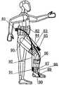
- Figure 1is a schematic structural diagram of Embodiment 1 of the present invention.
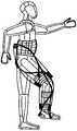
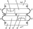
- Figure 2is a schematic structural diagram of Embodiment 2 of the present invention.
- FIG. 3is a schematic diagram of Embodiment 2 of the present invention which is different from Embodiment 1;
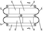
- Figure 5is a front view of the first joint control device in embodiment 1 of the present invention.
- Fig. 6is a left side view of the first joint control device in embodiment 1 of the present invention.
- Figure 7is a cross-sectional view A-A of Figure 5;
- Figure 8is a sectional view B-B of Figure 6;
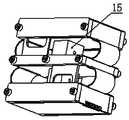
- Embodiment 9is a three-dimensional structure diagram of the second joint control device in Embodiment 1 of the present invention.
- FIG. 10is a front view of the second joint control device in Embodiment 1 of the present invention.
- Figure 11is a left side view of the second joint control device in embodiment 1 of the present invention.
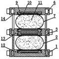
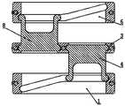
- Figure 12is a cross-sectional view C-C of Figure 10.
- Figure 13is a cross-sectional view D-D of Figure 11;
- 80-joint control device for lower ankle joint81-motor, 82-first fixation belt, 83-lifting Bowden line hip joint branch, 84-second fixation belt, 85-elevating hip joint joint control device, 86-Third fixation strap, 87-Fourth fixation strap, 88-Elevating Bowden line ankle joint branch, 89-Elevating ankle joint control device, 90-Fifth fixation strap, 91-Elevating knee joint Control device, 92-lifting Bowden wire knee joint branch, 93-lifting Bowden wire, 94-drop Bowden wire, 95-drop Bowden wire hip branch, 96-dropping hip joint control device, 97- Pull-down Bowden line knee joint branch, 98- pull down the knee joint with joint control device, 99- pull down Bowden line ankle joint branch.
- a wearable flexible power assist equipmentincludes a motor 81, a battery, a controller, a lifting Bowden cable 93, a first fixing belt 82, a second fixing belt 84, a third fixing belt 86, and a fourth fixing With 87, the fifth fixing belt 90 and 3 joint sub-control devices, the three joint sub-control devices are the joint sub-control device 85 for hip joint lifting, the joint sub-control device 91 for knee lifting and the joint sub-control device for ankle lifting ⁇ 89.
- the specific structure of the joint sub-control devicecan be the following two types of joint sub-controller mechanisms:
- the structure of the first joint control deviceis as follows:
- the joint control deviceincludes an electromagnetic coil 9 and three pole plates.
- the three pole platesare distributed in parallel at a certain interval along the thickness direction.
- the second pole plate 13 and the third pole plate 14are provided with a magnetorheological fluid storage capsule between the adjacent two pole plates.
- the magnetorheological fluid storage capsuleis made of highly elastic material, such as silica gel, etc.; specifically, the first pole plate 12 is connected to the The magnetorheological fluid storage capsule between the second pole plates 13 is the first magnetorheological fluid storage capsule 2, and the magnetorheological fluid storage capsule between the second pole plate 13 and the third pole plate 14 is the second magnetic current Variable fluid storage capsule 7; the bonding surfaces of the magnetorheological fluid storage capsule and its adjacent two pole plates are glued and fixed, and the magnetorheological fluid storage capsule is filled with magnetorheological fluid 11; the adjacent two pole plates form a pair of supporting and guiding structures
- the moving pairspecifically, the two sides of the second pole plate 13 are symmetrically fixed with a fixing block 3, a first guide plate 4 and a second guide plate 8, and the two sides of the first pole plate 12 are symmetrically fixed with a first guide block 1.
- the first guide block 1provides the first guide plate 4 with guide grooves and limit grooves for movement.
- the two sides of the third pole plate 14are symmetrically fixed with second guide blocks 6, and the second guide blocks 6 are second guides.
- the plate 8provides guide grooves and limit grooves for movement; the fixed block 3, the first guide plate 4 and the first guide block 1 together form a supporting and guiding structure between the first pole plate 12 and the second pole plate 13; the fixed block 3 ,
- the second guide plate 8 and the second guide block 6together constitute a supporting and guiding structure between the second electrode plate 13 and the third electrode plate 14; it also includes an elastic reset structure, which is used to reset the moved electrode plate To restore, the elastic reset structure selected in this embodiment includes two pairs of elastic rubber sheets 5.
- the beginning ends of the adjacent two electrode plates in the moving directionare connected by an elastic rubber sheet 5, and the ends of the adjacent two electrode plates in the moving direction are connected by an elastic rubber.
- the pieces 5are connected; the electromagnetic coil 9 is used to generate an electromagnetic field, the number of electromagnetic coils 9 is multiple, and the multiple electromagnetic coils 9 are distributed on the first pole plate 12, the second pole plate 13 and the third pole plate 14.
- the sealing plate 10seals and fixes the electromagnetic coil 9 in the pole plate.
- the structure of the second joint controlleris as follows:
- the joint sub-control deviceincludes an electromagnetic coil 9 and three pole plates.
- the three pole platesare distributed in parallel at a certain interval along the thickness direction.
- the second pole plate 13 and the third pole plate 14are provided with magnetorheological fluid storage capsules between adjacent two pole plates.
- the magnetorheological fluid storage capsulesare made of highly elastic material, such as silica gel, etc.; specifically, the first pole plate 12 is connected to the The magnetorheological fluid storage capsule between the second pole plates 13 is the first magnetorheological fluid storage capsule 2, and the magnetorheological fluid storage capsule between the second pole plate 13 and the third pole plate 14 is the second magnetic current Variable fluid storage capsule 7; the bonding surfaces of the magnetorheological fluid storage capsule and its adjacent two pole plates are glued and fixed, and the magnetorheological fluid storage capsule is filled with magnetorheological fluid 11; the adjacent two pole plates form a pair of supporting and guiding structures
- the moving pairspecifically, the two sides of the second pole plate 13 are symmetrically fixed with a fixing block 3, a first guide plate 4 and a second guide plate 8, and the two sides of the first pole plate 12 are symmetrically fixed with a first guide block 1.
- the first guide block 1provides the first guide plate 4 with guide grooves and limit grooves for movement.
- the two sides of the third pole plate 14are symmetrically fixed with second guide blocks 6, and the second guide blocks 6 are second guides.
- the plate 8provides a guide groove and a limit groove for movement;
- the fixed block 3, the first guide plate 4 and the first guide block 1together constitute a supporting and guiding structure between the first pole plate 12 and the second pole plate 13;
- the second guide plate 8 and the second guide block 6together constitute a supporting and guiding structure between the second pole plate 13 and the third pole plate 14;
- the guide path of the guide grooves on the first guide block 1 and the second guide block 6It is a broken line path, the setting of the broken line guide path makes the joint sub-control device have a certain degree of flexibility; it also includes an elastic reset structure, which is used to reset and restore the electrode plate after the movement.
- the elastic reset structure selected in this embodimentincludes Two pairs of elastic rubber sheets 5, the beginning ends of the adjacent two pole plates in the moving direction are connected by an elastic rubber sheet 5, and the ends of the adjacent two pole plates in the moving direction are connected by an elastic rubber sheet 5; the electromagnetic coil 9 is used to generate an electromagnetic field ,
- the number of electromagnetic coil 9is one, sealed and fixed inside the coil box 15, the coil box 15 is fixed on the second pole plate 13; the coil box 15 is provided with an overflow hole 1501, the overflow hole 1501 is a magnetorheological fluid 11, but does not destroy the sealing effect on the electromagnetic coil 9.
- Those skilled in the artcan design the size of the overflow hole according to the actual technical parameters.
- the position and size ratio of the overflow hole 1501 in the figureare only exemplary .
- the above-mentioned two kinds of joint controllersadopt the structure of 3 pole plates. Under the guidance of this embodiment, those skilled in the art can set reasonably according to the stroke size of the actual application and the deformation performance of the magnetorheological fluid storage bag. The number of plates.
- the first fixing strap 82is used for fixing on the waist of the human body
- the second fixing strap 84is used for fixing on the human thigh
- the third fixing strap 86is used for fixing on the upper half of the human leg
- the fourth fixing strapis used for fixing On the lower part of the human calf
- the fifth fixing strap 90is used to fix the human foot;
- the motor 81, the battery and the controllerare all fixed on the first fixing belt 82, and the battery is used to power the motor, the controller and the joint sub-control device; the first end plate of the joint sub-control device 85 for lifting the hip joint is fixed on On the second fixing belt 84, the first end plate of the joint control device 91 for lifting the knee joint is fixed on the fourth fixing belt 87, and the first end plate of the joint control device 89 for lifting the ankle joint is fixed on On the fifth fixing belt 90;
- the head end of the lifting Bowden cable 93is wound on the winding wheel, and the winding wheel is fixedly connected with the output shaft of the motor 81.
- the tail of the lifting Bowden cable 93includes three branch cables, which are the hip joint branches of the lifting Bowden cable. 83.
- Lifting Bowden line knee joint branch 92 and lifting Bowden line ankle joint branch 88, and the tail end of lifting Bowden line hip joint branch 83is fixedly connected with the second end plate of the joint sub-control device 85 for lifting hip joint
- the tail end of the lifting Bowden wire knee joint branch 92is fixedly connected with the second end plate of the lifting knee joint control device 91, and the tail end of the lifting Bowden wire ankle joint branch 88 is connected with the lifting ankle joint joint
- the second end plate of the control device 89is fixedly connected;
- the lifting Bowden wire knee joint branch 92is provided with anchor points on the second fixing belt 84, and the lifting Bowden wire ankle joint branch 88 is provided on the third fixing belt 86 Anchor point; when in use, the joint control device 85 for hip lifting is fixed on the front of the human thigh, the joint control device 91 for lifting knee joint is fixed on the back of the human calf, and the joint control device 89 for lifting ankle joint is fixed on the foot Close to the sole of the foot;
- the three joint sub-control devicesare respectively connected to the controller through corresponding current regulating circuits.
- a wearable flexible power assist equipmentincludes a motor 81, a battery, a controller, a lifting Bowden wire 93, a pull-down Bowden wire 94, a first fixing strap 82, a second fixing strap 84,
- the third fixation belt 86, the fourth fixation belt 87, the fifth fixation belt 90 and 6 joint control devices, the 6 joint control devicesare respectively the joint control device 85 for hip joint lifting and the joint control device for knee lifting Device 91, joint sub-control device 89 for lifting ankle joint, joint sub-control device 96 for lower hip joint, joint sub-control device 98 for lower knee joint, and joint sub-control device 80 for lower ankle joint.
- the specific structure of the joint sub-control deviceis the same as the two joint sub-control devices in the first embodiment.
- the first fixing strap 82is used for fixing on the waist of the human body
- the second fixing strap 84is used for fixing on the human thigh
- the third fixing strap 86is used for fixing on the upper half of the human leg
- the fourth fixing strapis used for fixing On the lower part of the human calf
- the fifth fixing strap 90is used to fix the human foot;
- the motor 81, the battery and the controllerare all fixed on the first fixing belt 82, and the battery is used to supply power to the motor, the controller and the joint sub-control device; the first end plate of the joint sub-control device 85 for lifting the hip joint is fixed on On the second fixing belt 84, the first end plate of the joint control device 91 for lifting the knee joint is fixed on the fourth fixing belt 87, and the first end plate of the joint control device 89 for lifting the ankle joint is fixed on On the fifth fixing belt 90;
- the head end of the lifting Bowden cable 93is wound on the winding wheel, and the winding wheel is fixedly connected with the output shaft of the motor 81.
- the tail of the lifting Bowden cable 93includes three branch cables, which are the hip joint branches of the lifting Bowden cable. 83.
- Lifting Bowden line knee joint branch 92 and lifting Bowden line ankle joint branch 88, and the tail end of lifting Bowden line hip joint branch 83is fixedly connected with the second end plate of the joint sub-control device 85 for lifting hip joint
- the tail end of the lifting Bowden wire knee joint branch 92is fixedly connected with the second end plate of the lifting knee joint control device 91, and the tail end of the lifting Bowden wire ankle joint branch 88 is connected with the lifting ankle joint joint
- the second end plate of the control device 89is fixedly connected;
- the lifting Bowden wire knee joint branch 92is provided with anchor points on the second fixing belt 84, and the lifting Bowden wire ankle joint branch 88 is provided on the third fixing belt 86 Anchor point; when in use, the joint control device 85 for hip lifting is fixed on the front of the human thigh, the joint control device 91 for lifting knee joint is fixed on the back of the human calf, and the joint control device 89 for lifting ankle joint is fixed on the foot Close to the sole of the foot;
- the first end plate of the joint control device 96 for pulling down the hip jointis fixed on the second fixing belt 84, and the first end plate of the joint control device 98 for pulling down the knee joint is fixed on the fourth fixing belt 87,
- the first end plate of the joint control device 80 for pulling down the ankle jointis fixed on the fifth fixing belt 90;
- the reelincludes a reel A and a reel B that are coaxially fixed in series and The head end of the Bowden wire 93 is wound on the reel A, the head end of the pull-down Bowden wire 94 is wound on the reel B, and the winding direction of the lifting Bowden wire 93 is opposite to that of the pull-down Bowden wire 94;
- the tail of 94includes three bifurcated lines, namely the hip branch 95 of the lower Bowden line, the knee branch 97 of the lower Bowden line, the ankle branch of the lower Bowden line 99, and the tail end of the hip branch 95 of the lower Bowden line It is fixedly connected to the second end plate of the lowered hip joint joint control
- the six joint sub-control devicesare respectively connected to the controller through corresponding current regulating circuits.
- Magnetorheological fluidis a suspension composed of small soft magnetic particles with high permeability and low hysteresis and a non-magnetic liquid; this type of suspension is in a zero magnetic field, the magnetorheological fluid behaves as A liquid with good flow properties has a very small apparent viscosity; it can increase its apparent viscosity by more than two orders of magnitude in a short time (milliseconds) under the action of a strong magnetic field, and exhibit solid-like characteristics; and this change is continuous, Reversible, that is, it returns to its original state after removing the magnetic field;
- the joint sub-control deviceWhen the magnetorheological fluid is in a low-viscosity liquid state, when the Bowden wire connected to it is pulled, the joint sub-control device will move due to the traction, and the traction required for its action is small; when the magnetorheological fluid has a high viscosity In the liquid state, when the Bowden wire connected to it is pulled, the joint sub-control device will act due to the traction, but the traction required for its action is relatively large; when the magnetorheological fluid is in a solid state, the connected abalone will be pulled After boarding the line, the joint sub-control device will basically not move due to traction; after the traction force of the Bowden cable is removed, the joint sub-control device will return to its original state through its elastic reset structure;
- the winding of the lifting Bowden wire 93will pull the second end plate of the lifting knee joint control device 91 to lift
- the joint control device 91 for the knee jointdoes not move, and it exerts a boosting effect on the bending action of the human knee joint;
- Motor 81rotates forward, lifting Bowden wire 93 is wound on reel A, pulling down Bowden wire 94 is unwound on reel B; motor reverses, lifting Bowden wire 93 is unwound on reel A Winding, the pull-down Bowden wire 94 is wound on the reel B.
Landscapes
- Engineering & Computer Science (AREA)
- Robotics (AREA)
- Mechanical Engineering (AREA)
- Rehabilitation Tools (AREA)
- Manipulator (AREA)
Abstract
Description
Translated fromChinese本发明涉及穿戴设备技术领域,具体涉及一种穿戴式柔性助力装备。The invention relates to the technical field of wearable equipment, in particular to a wearable flexible assisting equipment.
穿戴式柔性助力装备用于为人体关节动作提供助力,辅助人体动作,以降低人体代谢消耗、延缓身体疲劳。Wearable flexible power assistance equipment is used to provide assistance for the movement of human joints and assist human movement to reduce the body's metabolic consumption and delay body fatigue.
现有技术的柔性穿戴设备对人体各关节的控制一般都是联动控制,即采用一个动力源带动髋关节、膝关节和踝关节协同动作;为了实现各关节的单独控制,有的现有技术中采用一个动力源匹配一个关节的形式,这不仅导致了动力元件数量偏多,而且多个关节需要联动时,各动力元件的动作匹配性能也不佳、动作僵硬,达不到较理想的助力效果,从而导致较难被接受。The prior art flexible wearable device generally controls each joint of the human body by linkage control, that is, a power source is used to drive the hip joint, knee joint, and ankle joint to act in concert; in order to achieve individual control of each joint, some prior art The use of one power source to match one joint not only leads to a large number of power components, but also when multiple joints need to be linked, the motion matching performance of each power component is not good, the motion is stiff, and the ideal assist effect cannot be achieved. , Which makes it harder to be accepted.
发明内容Summary of the invention
本发明要解决的技术问题是弥补现有技术的不足,提供一种穿戴式柔性助力装备。The technical problem to be solved by the present invention is to make up for the shortcomings of the prior art and provide a wearable flexible assisting device.
要解决上述技术问题,本发明的技术方案为:To solve the above technical problems, the technical solution of the present invention is:
一种穿戴式柔性助力装备,包括电机、电池、控制器、提升鲍登线、第一固定带、第二固定带、第四固定带、第五固定带和多个关节分控装置,多个关节分控装置分别为提升髋关节用关节分控装置、提升膝关节用关节分控装置和提升踝关节用关节分控装置;A wearable flexible power-assisted equipment, including a motor, a battery, a controller, a lifting Bowden cable, a first fixing belt, a second fixing belt, a fourth fixing belt, a fifth fixing belt and multiple joint control devices, multiple The joint sub-control devices are joint sub-control devices for hip joint elevation, joint sub-control devices for knee joint elevation and joint sub-control devices for ankle joint elevation;
第一固定带用于固定在人体腰肢上,第二固定带用于固定在人体大腿部,第四固定带用于固定在人体小腿部,第五固定带用于固定在人体脚部;The first fixing strap is used for fixing on the waist of the human body, the second fixing strap is used for fixing on the human thigh, the fourth fixing strap is used for fixing on the lower leg of the human body, and the fifth fixing strap is used for fixing on the human foot. ;
电机、电池和控制器均固定在第一固定带上,电池用于给电机、控制器和关节分控装置供电;提升髋关节用关节分控装置固定在第二固定带上,提升膝关节用关节分控装置固定在第四固定带上,提升踝关节用关节分控装置固定在第五固定带上;The motor, battery and controller are all fixed on the first fixing belt, and the battery is used to supply power to the motor, controller and joint sub-control device; the joint sub-control device for lifting hip joint is fixed on the second fixing belt, which is used to lift the knee joint. The joint control device is fixed on the fourth fixing belt, and the joint control device for lifting the ankle joint is fixed on the fifth fixing belt;
提升鲍登线的首端缠绕于绕线轮上,绕线轮与电机的输出轴固定连接,提升鲍登线的尾部包括三支分叉线,分别为提升鲍登线髋关节分支、提升鲍登线膝关节分支和提升鲍登线踝关节分支,提升鲍登线髋关节分支的尾端与提升髋关节用关节分控装置的活动端固定连接,提升鲍登线膝关节分支的尾端与提升膝关节用关节分控装置的活动端固定连接,提升鲍登线踝关节分支的尾端与提升踝关节用关节分控装置的活动端固定连接。The head end of the lifting Bowden cable is wound on the winding wheel, and the winding wheel is fixedly connected with the output shaft of the motor. The tail of the lifting Bowden cable includes three bifurcated cables, which are the hip joint branch of the lifting Bowden cable and the lifting Bowden cable. The knee joint branch and the ankle joint branch of the lifting Bowden cable, the tail end of the hip branch of the lifting Bowden cable and the movable end of the joint control device for lifting the hip joint are fixedly connected, and the tail end of the knee joint branch of the lifting Bowden cable is connected with The movable end of the joint control device for lifting the knee joint is fixedly connected, and the tail end of the ankle joint branch of the lifting Bowden line is fixedly connected with the movable end of the joint control device for lifting the ankle joint.
进一步地,还包括下拉鲍登线,多个关节分控装置还包括下拉髋关节用关节分控装置、下拉膝关节用关节分控装置和下拉踝关节用关节分控装置;下拉髋关节用关节分控装置 固定在第二固定带上,下拉膝关节用关节分控装置固定在第四固定带上,下拉踝关节用关节分控装置固定在第五固定带上;所述绕线轮包括同轴固定串接的绕线轮A和绕线轮B,所述提升鲍登线的首端缠绕于绕线轮A上,下拉鲍登线的首端缠绕于绕线轮B上,提升鲍登线与下拉鲍登线绕向相反;下拉鲍登线的尾部包括三支分叉线,分别为下拉鲍登线髋关节分支、下拉鲍登线膝关节分支和下拉鲍登线踝关节分支,下拉鲍登线髋关节分支的尾端与下拉髋关节用关节分控装置的活动端固定连接,下拉鲍登线膝关节分支的尾端与下拉膝关节用关节分控装置的活动端固定连接,下拉鲍登线踝关节分支的尾端与下拉踝关节用关节分控装置的活动端固定连接。Further, it also includes a pull-down Bowden wire, and the multiple joint sub-control devices also include a joint sub-control device for pulling down the hip joint, a joint sub-control device for pulling down a knee joint, and a joint sub-controlling device for pulling down an ankle joint; and a joint for pulling down the hip joint The sub-control device is fixed on the second fixing belt, the lower knee joint is fixed on the fourth fixing belt with the joint control device, and the lower ankle joint is fixed on the fifth fixing belt with the joint control device; the winding wheel includes the same The shaft fixes the reel A and the reel B connected in series, the first end of the lifting Bowden wire is wound on the reel A, and the head end of the pull-down Bowden wire is wound on the reel B to lift the Bowden The winding direction of the lower Bowden wire is opposite; the tail of the lower Bowden wire includes three bifurcated wires, namely the hip branch of the lower Bowden wire, the knee branch of the lower Bowden wire, and the ankle branch of the lower Bowden wire. The tail end of the hip joint branch of Bowden wire is fixedly connected with the movable end of the joint control device for the pull-down hip joint, and the tail end of the knee joint branch of the pull-down Bowden wire is fixedly connected with the movable end of the joint control device for the pull-down knee joint. The tail end of the ankle joint branch of the Bowden wire is fixedly connected with the movable end of the joint control device for the lower ankle joint.
进一步地,多个关节分控装置分别通过相对应的电流调节电路与控制器相连。Further, multiple joint sub-control devices are respectively connected to the controller through corresponding current adjustment circuits.
进一步地,所述关节分控装置包括电磁线圈和多个极板,多个极板沿其厚度方向以一定间距平行分布,相邻两极板之间设有磁流变液储囊,磁流变液储囊为高弹材质,磁流变液储囊与其相邻两极板的贴合面均固定连接,磁流变液储囊中填充磁流变液;相邻两极板通过支撑导向结构构成一对移动副;还包括弹性复位结构,弹性复位结构用于使移动后的极板复位还原;电磁线圈用于产生电磁场。Further, the joint sub-control device includes an electromagnetic coil and a plurality of pole plates, the plurality of pole plates are distributed in parallel at a certain interval along the thickness direction, and a magnetorheological fluid storage capsule is arranged between the adjacent two pole plates. The liquid storage bag is made of high-elastic material. The bonding surfaces of the magnetorheological liquid storage bag and its adjacent two polar plates are fixedly connected, and the magnetorheological liquid storage bag is filled with magnetorheological liquid; the adjacent two polar plates form a supporting and guiding structure. The moving pair; also includes an elastic reset structure, which is used for resetting and restoring the polar plate after the movement; the electromagnetic coil is used for generating an electromagnetic field.
进一步地,所述关节分控装置的弹性复位结构包括多个弹性橡胶片,相邻两极板上沿移动方向的始端通过一个弹性橡胶片相连,相邻两极板上沿移动方向的终端通过一个弹性橡胶片相连,弹性橡胶片的数量与极板的数量相匹配。Further, the elastic reset structure of the joint control device includes a plurality of elastic rubber sheets, the beginning ends of the adjacent two polar plates in the moving direction are connected by an elastic rubber sheet, and the ends of the adjacent two polar plates in the moving direction are connected by an elastic rubber sheet. The rubber sheets are connected, and the number of elastic rubber sheets matches the number of pole plates.
进一步地,所述关节分控装置的极板的数量为3个,自下而上依次为第一极板、第二极板和第三极板;第二极板的两侧面对称固定设有固定块、第一导向板和第二导向板,第一极板的两侧面对称固定设有第一导向块,第一导向块为第一导向板提供移动用导向槽及限位槽,第三极板的两侧面对称固定设有第二导向块,第二导向块为第二导向板提供移动用导向槽及限位槽;固定块、第一导向板和第一导向块共同构成第一极板与第二极板之间的支撑导向结构;固定块、第二导向板和第二导向块共同构成第二极板与第三极板之间的支撑导向结构。Further, the number of the pole plates of the joint sub-control device is three, from bottom to top, the first pole plate, the second pole plate, and the third pole plate; the two sides of the second pole plate are symmetrically fixed The fixed block, the first guide plate and the second guide plate. The two sides of the first pole plate are symmetrically fixed with first guide blocks. The two sides of the pole plate are symmetrically fixed with a second guide block, the second guide block provides the second guide plate with a guide groove and a limit groove for movement; the fixed block, the first guide plate and the first guide block together constitute the first pole The supporting and guiding structure between the plate and the second plate; the fixed block, the second guiding plate and the second guiding block together constitute the supporting and guiding structure between the second plate and the third plate.
进一步地,所述关节分控装置的第一导向块和第二导向块上的导向槽的导向路径为折线路径。Further, the guide paths of the guide grooves on the first guide block and the second guide block of the joint control device are broken line paths.
进一步地,所述关节分控装置的电磁线圈的数量为多个,多个电磁线圈在所述第一极板、第二极板和第三极板上均有分布。Further, the number of electromagnetic coils of the joint sub-control device is multiple, and multiple electromagnetic coils are distributed on the first pole plate, the second pole plate, and the third pole plate.
进一步地,所述关节分控装置的电磁线圈的数量为1个,密封固定在线圈盒内部,线圈盒固定在所述第二极板上。Further, the number of electromagnetic coils of the joint sub-control device is one, which is sealed and fixed inside the coil box, and the coil box is fixed on the second pole plate.
进一步地,所述关节分控装置的线圈盒上设有溢流孔,溢流孔为磁流变液的流动通道,但不破坏对所述电磁线圈的密封效果。Further, the coil box of the joint sub-control device is provided with an overflow hole, and the overflow hole is a flow channel of a magnetorheological fluid, but does not damage the sealing effect of the electromagnetic coil.
本发明可以达到的有益效果为:The beneficial effects that can be achieved by the present invention are:
1)穿戴式柔性助力装备仅用一个电机作为动力源,既大大降低了人体负重,又大大提高了携带便捷性,且多个关节分控装置匹配性能佳,从而使助力动作流畅、助力效果好;1) Wearable flexible power assist equipment uses only one motor as the power source, which not only greatly reduces the weight of the human body, but also greatly improves the convenience of carrying. Moreover, the matching performance of multiple joint control devices is good, so that the power-assisted action is smooth and the power-assisted effect is good. ;
2)将关节分控装置与人体相对固定,将鲍登线与关节分控装置的活动端极板相连接,可以在一定程度上实现拉力传递的离与合,基本颠覆了传统离合器的概念;2) The joint sub-control device is relatively fixed to the human body, and the Bowden cable is connected to the movable end plate of the joint sub-control device, which can realize the clutching and closing of the tension transmission to a certain extent, which basically subverts the concept of the traditional clutch;
3)关节分控装置的磁流变液从液体状态转变为类固体状态所需的时间为毫秒级,相应速度非常快,且连续可逆;仅采用一个电机控制便可实现两种助力方式:对多个关节联动助力,对多个关节分别单独助力。3) The time required for the magnetorheological fluid of the joint sub-control device to transform from a liquid state to a solid-like state is milliseconds, the corresponding speed is very fast, and is continuously reversible; only one motor control can achieve two power assist methods: Multiple joints are linked to assist, and multiple joints are individually assisted.
图1是本发明实施例1的结构示意图;Figure 1 is a schematic structural diagram of
图2是本发明实施例2的结构示意图;Figure 2 is a schematic structural diagram of
图3是本发明实施例2区别于实施例1的示意图;FIG. 3 is a schematic diagram of
图4是本发明实施例1中第一种关节分控装置的立体结构图;4 is a three-dimensional structural diagram of the first joint sub-control device in
图5是本发明实施例1中第一种关节分控装置的主视图;Figure 5 is a front view of the first joint control device in
图6是本发明实施例1中第一种关节分控装置的左视图;Fig. 6 is a left side view of the first joint control device in
图7是图5的剖视图A-A;Figure 7 is a cross-sectional view A-A of Figure 5;
图8是图6的剖视图B-B;Figure 8 is a sectional view B-B of Figure 6;
图9是本发明实施例1中第二种关节分控装置的立体结构图;9 is a three-dimensional structure diagram of the second joint control device in
图10是本发明实施例1中第二种关节分控装置的主视图;10 is a front view of the second joint control device in
图11是本发明实施例1中第二种关节分控装置的左视图;Figure 11 is a left side view of the second joint control device in
图12是图10的剖视图C-C;Figure 12 is a cross-sectional view C-C of Figure 10;
图13是图11的剖视图D-D;Figure 13 is a cross-sectional view D-D of Figure 11;
图14是本发明实施例1中第二种关节分控装置在隐藏磁流变液储囊状态的立体结构图;14 is a three-dimensional structure diagram of the second joint sub-control device in the state where the magnetorheological fluid storage capsule is hidden in
图15是本发明实施例1中第二种关节分控装置中第二极板、线圈盒和电磁线圈的结构布置立体图;15 is a perspective view of the structural arrangement of the second pole plate, the coil box and the electromagnetic coil in the second type of joint control device in
图中:1-第一导向块,2-第一磁流变液储囊,3-固定块,4-第一导向板,5-弹性橡胶片,6-第二导向块,7-第二磁流变液储囊,8-第二导向板,9-电磁线圈,10-密封板,11-磁流变液,12-第一极板,13-第二极板,14-第三极板,15-线圈盒,1501-溢流孔;In the picture: 1-first guide block, 2-first magnetorheological fluid storage bag, 3-fixed block, 4-first guide plate, 5-elastic rubber sheet, 6-second guide block, 7-second Magnetorheological fluid storage bag, 8-second guide plate, 9-electromagnetic coil, 10-sealing plate, 11-magnetorheological fluid, 12-first pole, 13-second pole, 14-third pole Plate, 15-coil box, 1501-overflow hole;
80-下拉踝关节用关节分控装置,81-电机,82-第一固定带,83-提升鲍登线髋关节分支,84-第二固定带,85-提升髋关节用关节分控装置,86-第三固定带,87-第四固定带,88-提升鲍登线踝关节分支,89-提升踝关节用关节分控装置,90-第五固定带,91-提升膝关节用关节分控装置,92-提升鲍登线膝关节分支,93-提升鲍登线,94-下拉鲍登线,95-下拉鲍登线髋关节分支,96-下拉髋关节用关节分控装置,97-下拉鲍登线膝关节分支,98-下拉膝关节用关节分控装置,99-下拉鲍登线踝关节分支。80-joint control device for lower ankle joint, 81-motor, 82-first fixation belt, 83-lifting Bowden line hip joint branch, 84-second fixation belt, 85-elevating hip joint joint control device, 86-Third fixation strap, 87-Fourth fixation strap, 88-Elevating Bowden line ankle joint branch, 89-Elevating ankle joint control device, 90-Fifth fixation strap, 91-Elevating knee joint Control device, 92-lifting Bowden wire knee joint branch, 93-lifting Bowden wire, 94-drop Bowden wire, 95-drop Bowden wire hip branch, 96-dropping hip joint control device, 97- Pull-down Bowden line knee joint branch, 98- pull down the knee joint with joint control device, 99- pull down Bowden line ankle joint branch.
下面结合附图和具体实施方式对本发明作进一步详细的说明。The present invention will be further described in detail below in conjunction with the drawings and specific embodiments.
实施例1Example 1
如图1所示,一种穿戴式柔性助力装备,包括电机81、电池、控制器、提升鲍登线93、第一固定带82、第二固定带84、第三固定带86、第四固定带87、第五固定带90和3个关节分控装置,3个关节分控装置分别为提升髋关节用关节分控装置85、提升膝关节用关节分控装置91和提升踝关节用关节分控装置89。As shown in Figure 1, a wearable flexible power assist equipment includes a
关节分控装置的具体结构可以是下述两种关节分控器的机构:The specific structure of the joint sub-control device can be the following two types of joint sub-controller mechanisms:
第一种关节分控装置的结构如下:The structure of the first joint control device is as follows:
如图4-图8所示,关节分控装置包括电磁线圈9和3个极板,3个极板沿其厚度方向以一定间距平行分布,自下而上依次为第一极板12、第二极板13和第三极板14,相邻两极板之间设有磁流变液储囊,磁流变液储囊为高弹材质,如硅胶等;具体地,第一极板12与第二极板13之间的磁流变液储囊为第一磁流变液储囊2,第二极板13与第三极板14之间的磁流变液储囊为第二磁流变液储囊7;磁流变液储囊与其相邻两极板的贴合面均胶结固定,磁流变液储囊中填充磁流变液11;相邻两极板通过支撑导向结构构成一对移动副,具体地,第二极板13的两侧面对称固定设有固定块3、第一导向板4和第二导向板8,第一极板12的两侧面对称固定设有第一导向块1,第一导向块1为第一导向板4提供移动用导向槽及限位槽,第三极板14的两侧面对称固定设有第二导向块6,第二导向块6为第二导向板8提供移动用导向槽及限位槽;固定块3、第一导向板4和第一导向块1共同构成第一极板12与第二极板13之间的支撑导向结构;固定块3、第二导向板8和第二导向块6共同构成第二极板13与第三极板14之间的支撑导向结构;还包括弹性复位结构,弹性复位结构用于使移动后的极板复位还原,本实施例选用的弹性复位结构包括2对弹性橡胶片5,相邻两极板上沿移动方向的始端通过一个弹性橡胶片5相连,相邻两极板上沿移动方向的终端通过一个弹性橡胶片5相连;电磁线圈9用于产生电磁场,电磁线圈9的数量为多个,多个电磁线圈9 在第一极板12、第二极板13和第三极板14上均有分布,采用密封板10将电磁线圈9密封固定于极板中。As shown in Figures 4-8, the joint control device includes an
第二种关节分控器的结构如下:The structure of the second joint controller is as follows:
如图9-图15所示,关节分控装置包括电磁线圈9和3个极板,3个极板沿其厚度方向以一定间距平行分布,自下而上依次为第一极板12、第二极板13和第三极板14,相邻两极板之间设有磁流变液储囊,磁流变液储囊为高弹材质,如硅胶等;具体地,第一极板12与第二极板13之间的磁流变液储囊为第一磁流变液储囊2,第二极板13与第三极板14之间的磁流变液储囊为第二磁流变液储囊7;磁流变液储囊与其相邻两极板的贴合面均胶结固定,磁流变液储囊中填充磁流变液11;相邻两极板通过支撑导向结构构成一对移动副,具体地,第二极板13的两侧面对称固定设有固定块3、第一导向板4和第二导向板8,第一极板12的两侧面对称固定设有第一导向块1,第一导向块1为第一导向板4提供移动用导向槽及限位槽,第三极板14的两侧面对称固定设有第二导向块6,第二导向块6为第二导向板8提供移动用导向槽及限位槽;固定块3、第一导向板4和第一导向块1共同构成第一极板12与第二极板13之间的支撑导向结构;固定块3、第二导向板8和第二导向块6共同构成第二极板13与第三极板14之间的支撑导向结构;第一导向块1和第二导向块6上的导向槽的导向路径为折线路径,折线式导向路径的设置使关节分控装置本身具备一定的柔性;还包括弹性复位结构,弹性复位结构用于使移动后的极板复位还原,本实施例选用的弹性复位结构包括2对弹性橡胶片5,相邻两极板上沿移动方向的始端通过一个弹性橡胶片5相连,相邻两极板上沿移动方向的终端通过一个弹性橡胶片5相连;电磁线圈9用于产生电磁场,电磁线圈9的数量为1个,密封固定在线圈盒15内部,线圈盒15固定在第二极板13上;线圈盒15上设有溢流孔1501,溢流孔1501为磁流变液11的流动通道,但不破坏对电磁线圈9的密封效果,本领域技术人员可以根据实际技术参数设计溢流孔的大小,附图中的溢流孔1501的位置及大小比例仅为示例性的。As shown in Figures 9-15, the joint sub-control device includes an
上述两种关节分控器采用的均为3个极板的结构,本领域技术人员可以在本实施例的指导下,根据实际应用的行程大小和磁流变液储囊的形变性能合理地设置极板的数量。The above-mentioned two kinds of joint controllers adopt the structure of 3 pole plates. Under the guidance of this embodiment, those skilled in the art can set reasonably according to the stroke size of the actual application and the deformation performance of the magnetorheological fluid storage bag. The number of plates.
第一固定带82用于固定在人体腰肢上,第二固定带84用于固定在人体大腿部,第三固定带86用于固定在人体小腿上半部,第四固定带用于固定在人体小腿下半部,第五固定带90用于固定在人体脚部;The
电机81、电池和控制器均固定在第一固定带82上,电池用于给电机、控制器和关节分控装置供电;提升髋关节用关节分控装置85的第一端部极板固定在第二固定带84上,提升膝关 节用关节分控装置91的第一端部极板固定在第四固定带87上,提升踝关节用关节分控装置89的第一端部极板固定在第五固定带90上;The
提升鲍登线93的首端缠绕于绕线轮上,绕线轮与电机81的输出轴固定连接,提升鲍登线93的尾部包括三支分叉线,分别为提升鲍登线髋关节分支83、提升鲍登线膝关节分支92和提升鲍登线踝关节分支88,提升鲍登线髋关节分支83的尾端与提升髋关节用关节分控装置85的第二端部极板固定连接,提升鲍登线膝关节分支92的尾端与提升膝关节用关节分控装置91的第二端部极板固定连接,提升鲍登线踝关节分支88的尾端与提升踝关节用关节分控装置89的第二端部极板固定连接;提升鲍登线膝关节分支92在第二固定带84上设有锚固点,提升鲍登线踝关节分支88在第三固定带86上设有锚固点;使用时,提升髋关节用关节分控装置85固定在人体大腿的正面,提升膝关节用关节分控装置91固定在人体小腿的背面,提升踝关节用关节分控装置89固定在脚部靠近脚掌;The head end of the lifting
3个关节分控装置分别通过相对应的电流调节电路与控制器相连。The three joint sub-control devices are respectively connected to the controller through corresponding current regulating circuits.
实施例2Example 2
如图2和图3所示,一种穿戴式柔性助力装备,包括电机81、电池、控制器、提升鲍登线93、下拉鲍登线94、第一固定带82、第二固定带84、第三固定带86、第四固定带87、第五固定带90和6个关节分控装置,6个关节分控装置分别为提升髋关节用关节分控装置85、提升膝关节用关节分控装置91、提升踝关节用关节分控装置89、下拉髋关节用关节分控装置96、下拉膝关节用关节分控装置98和下拉踝关节用关节分控装置80。As shown in Figures 2 and 3, a wearable flexible power assist equipment includes a
关节分控装置的具体结构与实施例1中的两种关节分控装置相同。The specific structure of the joint sub-control device is the same as the two joint sub-control devices in the first embodiment.
第一固定带82用于固定在人体腰肢上,第二固定带84用于固定在人体大腿部,第三固定带86用于固定在人体小腿上半部,第四固定带用于固定在人体小腿下半部,第五固定带90用于固定在人体脚部;The
电机81、电池和控制器均固定在第一固定带82上,电池用于给电机、控制器和关节分控装置供电;提升髋关节用关节分控装置85的第一端部极板固定在第二固定带84上,提升膝关节用关节分控装置91的第一端部极板固定在第四固定带87上,提升踝关节用关节分控装置89的第一端部极板固定在第五固定带90上;The
提升鲍登线93的首端缠绕于绕线轮上,绕线轮与电机81的输出轴固定连接,提升鲍登线93的尾部包括三支分叉线,分别为提升鲍登线髋关节分支83、提升鲍登线膝关节分支92和提升鲍登线踝关节分支88,提升鲍登线髋关节分支83的尾端与提升髋关节用关节分控装置85的第二端部极板固定连接,提升鲍登线膝关节分支92的尾端与提升膝关节用关节分控装 置91的第二端部极板固定连接,提升鲍登线踝关节分支88的尾端与提升踝关节用关节分控装置89的第二端部极板固定连接;提升鲍登线膝关节分支92在第二固定带84上设有锚固点,提升鲍登线踝关节分支88在第三固定带86上设有锚固点;使用时,提升髋关节用关节分控装置85固定在人体大腿的正面,提升膝关节用关节分控装置91固定在人体小腿的背面,提升踝关节用关节分控装置89固定在脚部靠近脚掌;The head end of the lifting
下拉髋关节用关节分控装置96的第一端部极板固定在第二固定带84上,下拉膝关节用关节分控装置98的第一端部极板固定在第四固定带87上,下拉踝关节用关节分控装置80的第一端部极板固定在第五固定带90上;所述绕线轮包括同轴固定串接的绕线轮A和绕线轮B,所述提升鲍登线93的首端缠绕于绕线轮A上,下拉鲍登线94的首端缠绕于绕线轮B上,提升鲍登线93与下拉鲍登线94绕向相反;下拉鲍登线94的尾部包括三支分叉线,分别为下拉鲍登线髋关节分支95、下拉鲍登线膝关节分支97和下拉鲍登线踝关节分支99,下拉鲍登线髋关节分支95的尾端与下拉髋关节用关节分控装置96的第二端部极板固定连接,下拉鲍登线膝关节分支97的尾端与下拉膝关节用关节分控装置98的第二端部极板固定连接,下拉鲍登线踝关节分支99的尾端与下拉踝关节用关节分控装置80的第二端部极板;下拉鲍登线膝关节分支97在第二固定带84上设有锚固点,下拉鲍登线踝关节分支99在第四固定带87上设有锚固点;使用时,下拉髋关节用关节分控装置96固定在人体大腿的背面,下拉膝关节用关节分控装置98固定在人体小腿的正面,下拉踝关节用关节分控装置80固定在脚部靠近脚后跟处;The first end plate of the joint control device 96 for pulling down the hip joint is fixed on the second fixing belt 84, and the first end plate of the joint control device 98 for pulling down the knee joint is fixed on the fourth fixing belt 87, The first end plate of the joint control device 80 for pulling down the ankle joint is fixed on the fifth fixing belt 90; the reel includes a reel A and a reel B that are coaxially fixed in series and The head end of the Bowden wire 93 is wound on the reel A, the head end of the pull-down Bowden wire 94 is wound on the reel B, and the winding direction of the lifting Bowden wire 93 is opposite to that of the pull-down Bowden wire 94; The tail of 94 includes three bifurcated lines, namely the hip branch 95 of the lower Bowden line, the knee branch 97 of the lower Bowden line, the ankle branch of the lower Bowden line 99, and the tail end of the hip branch 95 of the lower Bowden line It is fixedly connected to the second end plate of the lowered hip joint joint control device 96, and the tail end of the lower Bowden line knee joint branch 97 is fixedly connected to the second end plate of the lowered knee joint joint control device 98 , The tail end of the ankle joint branch 99 of the pull-down Bowden wire and the second end plate of the joint control device 80 for the pull-down ankle joint; the knee joint branch 97 of the pull-down Bowden wire is provided with an anchor point on the second fixing strap 84, The ankle joint branch 99 of the pull-down Bowden line is provided with an anchor point on the fourth fixing strap 87; when in use, the joint control device 96 for pull-down hip joint is fixed on the back of the human thigh, and the knee joint is fixed on the back of the human thigh. On the front of the human calf, pull down the ankle joint and fix it on the foot near the heel with the
6个关节分控装置分别通过相对应的电流调节电路与控制器相连。The six joint sub-control devices are respectively connected to the controller through corresponding current regulating circuits.
上述实施例的原理:The principle of the above embodiment:
1)磁流变液是由高磁导率、低磁滞性的微小软磁性颗粒和非导磁性液体混合而成的悬浮体;这种悬浮体在零磁场情况下,磁流变液表现为流动性能良好的液体,其表观粘度很小;在强磁场作用下可在短时间(毫秒级)内表观粘度增加两个数量级以上,并呈现类固体特性;而且这种变化是连续的、可逆的,即去掉磁场后又恢复到原来的状态;1) Magnetorheological fluid is a suspension composed of small soft magnetic particles with high permeability and low hysteresis and a non-magnetic liquid; this type of suspension is in a zero magnetic field, the magnetorheological fluid behaves as A liquid with good flow properties has a very small apparent viscosity; it can increase its apparent viscosity by more than two orders of magnitude in a short time (milliseconds) under the action of a strong magnetic field, and exhibit solid-like characteristics; and this change is continuous, Reversible, that is, it returns to its original state after removing the magnetic field;
2)通过控制器和各电流调节电路调控各关节分控装置的通断电及通电电流强弱,使各关节分控装置中的磁流变液11呈不同的状态:低粘度液体状态、高粘度液体状态和类固体状态;2) Through the controller and each current adjustment circuit, the power on and off of each joint sub-control device and the strength of the energizing current are adjusted, so that the
当磁流变液呈低粘度液体状态时,牵引与其相连的鲍登线,关节分控装置会因牵引力而发生动作,且其发生动作所需的牵引力较小;当磁流变液呈高粘度液体状态时,牵引与其相连的鲍登线,关节分控装置会因牵引力而发生动作,但其发生动作所需的牵引力较大;当磁流变 液呈类固体状态时,牵引与其相连的鲍登线,关节分控装置基本不会因牵引力而发生动作;撤销鲍登线的牵引力之后,关节分控装置通过其弹性复位结构回复原状;When the magnetorheological fluid is in a low-viscosity liquid state, when the Bowden wire connected to it is pulled, the joint sub-control device will move due to the traction, and the traction required for its action is small; when the magnetorheological fluid has a high viscosity In the liquid state, when the Bowden wire connected to it is pulled, the joint sub-control device will act due to the traction, but the traction required for its action is relatively large; when the magnetorheological fluid is in a solid state, the connected abalone will be pulled After boarding the line, the joint sub-control device will basically not move due to traction; after the traction force of the Bowden cable is removed, the joint sub-control device will return to its original state through its elastic reset structure;
以控制膝关节的提升动作助力为例进行解释:Take the control of knee joint lifting motion assistance as an example to explain:
当提升膝关节用关节分控装置91中的磁流变液11呈低粘度液体状态时,提升鲍登线93的缠绕会牵引提升膝关节用关节分控装置91的第二端部极板,提升膝关节用关节分控装置91动作,导致其不会对人体膝关节进行弯曲动作有任何帮助;When the
当提升膝关节用关节分控装置91中的磁流变液11呈类固体状态时,提升鲍登线93的缠绕会牵引提升膝关节用关节分控装置91的第二端部极板,提升膝关节用关节分控装置91不动作,则发挥对人体膝关节进行弯曲动作的助力作用;When the
因而,可以通过调控各关节分控装置的通断电及通电电流强弱,实现通过一个电机81控制两路鲍登线总线进而对各关节的动作分别进行助力强度控制。Therefore, it is possible to control the two Bowden wire buses through one
3)电机81正转,提升鲍登线93在绕线轮A上缠绕,下拉鲍登线94在绕线轮B上解缠绕;电机反转,提升鲍登线93在绕线轮A上解缠绕,下拉鲍登线94在绕线轮B上缠绕。3)
上述实施例的优点:Advantages of the above embodiment:
1)实现了一个电机控制对多个关节的助力;1) Achieve a motor control to assist multiple joints;
2)通过控制各关节分控装置的状态,实现了对多个关节的助力既可联动、又可分别动作;2) By controlling the state of each joint sub-control device, the power assist for multiple joints can be linked and acted separately;
3)仅用一个电机,既大大降低了人体负重,又大大提高了携带便捷性。3) Only one motor is used, which not only greatly reduces the weight of the human body, but also greatly improves the portability.
在本发明的描述中,“内”、“外”、“上”、“下”、“前”、“后”等指示方位或位置关系的词语,仅是为了便于描述本发明,而不是指示或暗示所指的装置或元件必须具有特定的方位、以特定的方位构造和操作,因此不能理解为对本发明的限制。In the description of the present invention, words such as "inner", "outer", "upper", "lower", "front", "rear" and other words indicating the orientation or positional relationship are only used to facilitate the description of the present invention, rather than indicating It may also imply that the device or element referred to must have a specific orientation, be constructed and operated in a specific orientation, and therefore cannot be understood as a limitation of the present invention.
以上所述仅是本发明的其中一种实施方式,本发明的保护范围并不仅局限于上述实施例,应当指出,对于本技术领域的普通技术人员来说,在不脱离本发明思路的前提下所做出的若干改进和润饰均为本发明的保护范围。The above is only one of the embodiments of the present invention. The scope of protection of the present invention is not limited to the above-mentioned embodiments. Several improvements and modifications made are within the protection scope of the present invention.
Claims (10)
Translated fromChineseApplications Claiming Priority (2)
| Application Number | Priority Date | Filing Date | Title |
|---|---|---|---|
| CN202010360789.7 | 2020-04-30 | ||
| CN202010360789.7ACN111409061B (en) | 2020-04-30 | 2020-04-30 | A wearable flexible power-assisting device |
Publications (1)
| Publication Number | Publication Date |
|---|---|
| WO2021218049A1true WO2021218049A1 (en) | 2021-11-04 |
Family
ID=71488603
Family Applications (1)
| Application Number | Title | Priority Date | Filing Date |
|---|---|---|---|
| PCT/CN2020/121352CeasedWO2021218049A1 (en) | 2020-04-30 | 2020-10-16 | Wearable flexible power assist apparatus |
Country Status (2)
| Country | Link |
|---|---|
| CN (1) | CN111409061B (en) |
| WO (1) | WO2021218049A1 (en) |
Families Citing this family (5)
| Publication number | Priority date | Publication date | Assignee | Title |
|---|---|---|---|---|
| CN111409061B (en)* | 2020-04-30 | 2024-11-26 | 济南猫爪智能机械有限公司 | A wearable flexible power-assisting device |
| CN112223255B (en)* | 2020-08-27 | 2022-06-07 | 中国科学院深圳先进技术研究院 | Joint driving device and control method thereof |
| CN116637006B (en)* | 2023-05-25 | 2025-10-03 | 中国科学院深圳先进技术研究院 | A multi-joint flexible lower limb exoskeleton for children with cerebral palsy |
| WO2024239603A1 (en)* | 2023-05-25 | 2024-11-28 | 中国科学院深圳先进技术研究院 | Multi-joint flexible lower-limb exoskeleton for children with cerebral palsy |
| CN119610059A (en)* | 2024-12-18 | 2025-03-14 | 同济大学 | An underwater power-assisted flexible exoskeleton system |
Citations (7)
| Publication number | Priority date | Publication date | Assignee | Title |
|---|---|---|---|---|
| CN105992554A (en)* | 2013-12-09 | 2016-10-05 | 哈佛大学校长及研究员协会 | Assistive flexible suits, flexible suit systems, and methods of manufacture and control thereof for assisting human mobility |
| CN206123637U (en)* | 2013-03-15 | 2017-04-26 | Sri国际公司 | Human reinforcing system |
| CN106798629A (en)* | 2015-11-26 | 2017-06-06 | 三星电子株式会社 | Frame assembly and the exercise aid device including frame assembly |
| CN107486842A (en)* | 2017-09-27 | 2017-12-19 | 北京工业大学 | A kind of wearable hip joint flexibility power-assisted coat |
| KR20190000172A (en)* | 2017-06-22 | 2019-01-02 | 주식회사 에프알티 | Flexible joint for auxetic suit |
| US20190374161A1 (en)* | 2018-06-08 | 2019-12-12 | Seismic Holdings, Inc. | Exosuit systems and methods for detecting and analyzing lifting and bending |
| CN111409061A (en)* | 2020-04-30 | 2020-07-14 | 济南猫爪智能机械有限公司 | Flexible helping hand of wearing formula is equipped |
Family Cites Families (5)
| Publication number | Priority date | Publication date | Assignee | Title |
|---|---|---|---|---|
| WO2011129778A1 (en)* | 2010-04-12 | 2011-10-20 | Mehmet Agrikli | Direct traverse device |
| CN107081748B (en)* | 2017-06-16 | 2023-06-16 | 洛阳理工学院 | Gas or liquid mechanical muscle group |
| CN107648017B (en)* | 2017-11-09 | 2021-02-23 | 上海司羿智能科技有限公司 | Exoskeleton driving device, assisting exoskeleton system and driving and assisting method thereof |
| CN109662869B (en)* | 2019-01-21 | 2024-02-02 | 中国科学院沈阳自动化研究所 | Wearable flexible lower limb power-assisted robot |
| CN212044725U (en)* | 2020-04-30 | 2020-12-01 | 济南猫爪智能机械有限公司 | Flexible helping hand of wearing formula is equipped |
- 2020
- 2020-04-30CNCN202010360789.7Apatent/CN111409061B/enactiveActive
- 2020-10-16WOPCT/CN2020/121352patent/WO2021218049A1/ennot_activeCeased
Patent Citations (7)
| Publication number | Priority date | Publication date | Assignee | Title |
|---|---|---|---|---|
| CN206123637U (en)* | 2013-03-15 | 2017-04-26 | Sri国际公司 | Human reinforcing system |
| CN105992554A (en)* | 2013-12-09 | 2016-10-05 | 哈佛大学校长及研究员协会 | Assistive flexible suits, flexible suit systems, and methods of manufacture and control thereof for assisting human mobility |
| CN106798629A (en)* | 2015-11-26 | 2017-06-06 | 三星电子株式会社 | Frame assembly and the exercise aid device including frame assembly |
| KR20190000172A (en)* | 2017-06-22 | 2019-01-02 | 주식회사 에프알티 | Flexible joint for auxetic suit |
| CN107486842A (en)* | 2017-09-27 | 2017-12-19 | 北京工业大学 | A kind of wearable hip joint flexibility power-assisted coat |
| US20190374161A1 (en)* | 2018-06-08 | 2019-12-12 | Seismic Holdings, Inc. | Exosuit systems and methods for detecting and analyzing lifting and bending |
| CN111409061A (en)* | 2020-04-30 | 2020-07-14 | 济南猫爪智能机械有限公司 | Flexible helping hand of wearing formula is equipped |
Also Published As
| Publication number | Publication date |
|---|---|
| CN111409061A (en) | 2020-07-14 |
| CN111409061B (en) | 2024-11-26 |
Similar Documents
| Publication | Publication Date | Title |
|---|---|---|
| WO2021218049A1 (en) | Wearable flexible power assist apparatus | |
| CN107972754B (en) | A shape memory alloy driven soft crawling robot | |
| Manna et al. | Comparative study of actuation systems for portable upper limb exoskeletons | |
| CN111685966B (en) | A finger movement function rehabilitation device driven by shape memory alloy wire | |
| KR102496582B1 (en) | A driving module and a motion assist apparatus comprising thereof | |
| CN205394591U (en) | Flexible electromagnetic drive machinery joint | |
| CN108743227B (en) | Flexible exoskeleton wrist function rehabilitation device based on spring piece driving | |
| Homma et al. | Design of an upper limb motion assist system with parallel mechanism | |
| CN108498287B (en) | Rehabilitation training device and rehabilitation training system | |
| CN106074133B (en) | A kind of device for resuscitating heart and pulmones | |
| CN113367935B (en) | Flexible drive knee joint rehabilitation robot | |
| CN111390879B (en) | A joint sub-control device for flexible power-assist equipment | |
| CN212044725U (en) | Flexible helping hand of wearing formula is equipped | |
| KR20160031603A (en) | Assisting device for muscle strength | |
| CN107049704A (en) | A kind of flexible upper limbs ectoskeleton of auxiliary power | |
| CN106038168A (en) | Finger rehabilitation training device | |
| CN211992981U (en) | Joint sub-control device for flexible power-assisted equipment | |
| CN111546318B (en) | An improved joint sub-control device for flexible power-assist equipment | |
| CN212385474U (en) | Improved joint sub-control device for flexible power-assisted equipment | |
| CN204501517U (en) | Finger automatic exercise device | |
| CN215920448U (en) | Active exoskeleton robot | |
| CN212653444U (en) | A booster device for lower extremity exoskeleton | |
| CN114099256B (en) | Wearable flexible lower limb assistance exoskeleton | |
| CN117124298A (en) | Single-motor flexible walking-assisting exoskeleton | |
| CN219501465U (en) | Non-active module device for limb rehabilitation |
Legal Events
| Date | Code | Title | Description |
|---|---|---|---|
| 121 | Ep: the epo has been informed by wipo that ep was designated in this application | Ref document number:20933167 Country of ref document:EP Kind code of ref document:A1 | |
| NENP | Non-entry into the national phase | Ref country code:DE | |
| 122 | Ep: pct application non-entry in european phase | Ref document number:20933167 Country of ref document:EP Kind code of ref document:A1 | |
| 122 | Ep: pct application non-entry in european phase | Ref document number:20933167 Country of ref document:EP Kind code of ref document:A1 |