WO2021217373A1 - Suturing device, and treatment apparatus and treatment system having suturing device - Google Patents
Suturing device, and treatment apparatus and treatment system having suturing deviceDownload PDFInfo
- Publication number
- WO2021217373A1 WO2021217373A1PCT/CN2020/087329CN2020087329WWO2021217373A1WO 2021217373 A1WO2021217373 A1WO 2021217373A1CN 2020087329 WCN2020087329 WCN 2020087329WWO 2021217373 A1WO2021217373 A1WO 2021217373A1
- Authority
- WO
- WIPO (PCT)
- Prior art keywords
- needle
- suture
- endoscope
- suture needle
- assembly
- Prior art date
- Legal status (The legal status is an assumption and is not a legal conclusion. Google has not performed a legal analysis and makes no representation as to the accuracy of the status listed.)
- Ceased
Links
Images


Classifications
- A—HUMAN NECESSITIES
- A61—MEDICAL OR VETERINARY SCIENCE; HYGIENE
- A61B—DIAGNOSIS; SURGERY; IDENTIFICATION
- A61B17/00—Surgical instruments, devices or methods
- A61B17/04—Surgical instruments, devices or methods for suturing wounds; Holders or packages for needles or suture materials
- A61B17/0469—Suturing instruments for use in minimally invasive surgery, e.g. endoscopic surgery
- A—HUMAN NECESSITIES
- A61—MEDICAL OR VETERINARY SCIENCE; HYGIENE
- A61B—DIAGNOSIS; SURGERY; IDENTIFICATION
- A61B1/00—Instruments for performing medical examinations of the interior of cavities or tubes of the body by visual or photographical inspection, e.g. endoscopes; Illuminating arrangements therefor
- A61B1/00064—Constructional details of the endoscope body
- A61B1/00071—Insertion part of the endoscope body
- A61B1/0008—Insertion part of the endoscope body characterised by distal tip features
- A61B1/00087—Tools
- A—HUMAN NECESSITIES
- A61—MEDICAL OR VETERINARY SCIENCE; HYGIENE
- A61B—DIAGNOSIS; SURGERY; IDENTIFICATION
- A61B1/00—Instruments for performing medical examinations of the interior of cavities or tubes of the body by visual or photographical inspection, e.g. endoscopes; Illuminating arrangements therefor
- A61B1/00131—Accessories for endoscopes
- A61B1/0014—Fastening element for attaching accessories to the outside of an endoscope, e.g. clips, clamps or bands
- A—HUMAN NECESSITIES
- A61—MEDICAL OR VETERINARY SCIENCE; HYGIENE
- A61B—DIAGNOSIS; SURGERY; IDENTIFICATION
- A61B17/00—Surgical instruments, devices or methods
- A61B17/04—Surgical instruments, devices or methods for suturing wounds; Holders or packages for needles or suture materials
- A61B17/0482—Needle or suture guides
- A—HUMAN NECESSITIES
- A61—MEDICAL OR VETERINARY SCIENCE; HYGIENE
- A61B—DIAGNOSIS; SURGERY; IDENTIFICATION
- A61B17/00—Surgical instruments, devices or methods
- A61B17/04—Surgical instruments, devices or methods for suturing wounds; Holders or packages for needles or suture materials
- A61B17/06—Needles ; Sutures; Needle-suture combinations; Holders or packages for needles or suture materials
- A61B17/062—Needle manipulators
- A—HUMAN NECESSITIES
- A61—MEDICAL OR VETERINARY SCIENCE; HYGIENE
- A61B—DIAGNOSIS; SURGERY; IDENTIFICATION
- A61B17/00—Surgical instruments, devices or methods
- A61B17/32—Surgical cutting instruments
- A61B17/3205—Excision instruments
- A61B17/32056—Surgical snare instruments
- A—HUMAN NECESSITIES
- A61—MEDICAL OR VETERINARY SCIENCE; HYGIENE
- A61B—DIAGNOSIS; SURGERY; IDENTIFICATION
- A61B17/00—Surgical instruments, devices or methods
- A61B17/04—Surgical instruments, devices or methods for suturing wounds; Holders or packages for needles or suture materials
- A61B17/0483—Hand-held instruments for holding sutures
- A—HUMAN NECESSITIES
- A61—MEDICAL OR VETERINARY SCIENCE; HYGIENE
- A61B—DIAGNOSIS; SURGERY; IDENTIFICATION
- A61B17/00—Surgical instruments, devices or methods
- A61B17/00234—Surgical instruments, devices or methods for minimally invasive surgery
- A61B2017/00292—Surgical instruments, devices or methods for minimally invasive surgery mounted on or guided by flexible, e.g. catheter-like, means
- A61B2017/00296—Surgical instruments, devices or methods for minimally invasive surgery mounted on or guided by flexible, e.g. catheter-like, means mounted on an endoscope
- A—HUMAN NECESSITIES
- A61—MEDICAL OR VETERINARY SCIENCE; HYGIENE
- A61B—DIAGNOSIS; SURGERY; IDENTIFICATION
- A61B17/00—Surgical instruments, devices or methods
- A61B2017/00367—Details of actuation of instruments, e.g. relations between pushing buttons, or the like, and activation of the tool, working tip, or the like
- A61B2017/00407—Ratchet means
- A—HUMAN NECESSITIES
- A61—MEDICAL OR VETERINARY SCIENCE; HYGIENE
- A61B—DIAGNOSIS; SURGERY; IDENTIFICATION
- A61B17/00—Surgical instruments, devices or methods
- A61B2017/00477—Coupling
- A—HUMAN NECESSITIES
- A61—MEDICAL OR VETERINARY SCIENCE; HYGIENE
- A61B—DIAGNOSIS; SURGERY; IDENTIFICATION
- A61B17/00—Surgical instruments, devices or methods
- A61B17/04—Surgical instruments, devices or methods for suturing wounds; Holders or packages for needles or suture materials
- A61B17/0469—Suturing instruments for use in minimally invasive surgery, e.g. endoscopic surgery
- A61B2017/0474—Knot pushers
- A—HUMAN NECESSITIES
- A61—MEDICAL OR VETERINARY SCIENCE; HYGIENE
- A61B—DIAGNOSIS; SURGERY; IDENTIFICATION
- A61B17/00—Surgical instruments, devices or methods
- A61B17/04—Surgical instruments, devices or methods for suturing wounds; Holders or packages for needles or suture materials
- A61B17/06—Needles ; Sutures; Needle-suture combinations; Holders or packages for needles or suture materials
- A61B17/06066—Needles, e.g. needle tip configurations
- A61B2017/0608—J-shaped
- A—HUMAN NECESSITIES
- A61—MEDICAL OR VETERINARY SCIENCE; HYGIENE
- A61B—DIAGNOSIS; SURGERY; IDENTIFICATION
- A61B90/00—Instruments, implements or accessories specially adapted for surgery or diagnosis and not covered by any of the groups A61B1/00 - A61B50/00, e.g. for luxation treatment or for protecting wound edges
- A61B90/08—Accessories or related features not otherwise provided for
- A61B2090/0807—Indication means
Definitions
- the inventionrelates to a treatment device, in particular to a stapler, a treatment device with the stapler, and a treatment system.
- Non-invasive surgeryenters the operation area through the human body's natural cavity (such as human esophagus, rectum, uterus, etc.) without external wounds and less bleeding. It not only reduces the patient's physical and psychological trauma, but also reduces the depth of anesthesia and greatly reduces the risk of anesthesia. Non-invasive surgery can effectively reduce postoperative complications and is more beneficial to patients with higher risks.
- US Patent No. US7344545discloses an endoscopic suture system for surgical operations, which operates outside the body and sutures inside the body to achieve the purpose of treatment.
- This suturing systemincludes an assembly with first and second arms and a needle recovery member, which needs to be rigidly aligned with the curved needle arm.
- the arrangement of the tissue grasping arm and the needle recovery membermakes the system bulky, making it difficult for practical application in endoscopic surgery.
- Apollo Intracorporeal Surgeryhas also disclosed an endoscopic suture system. It can be used with an endoscope or other steering-guided devices to insert the stapler device into the body through the natural cavity of the human body.
- the systemhas a complex structure, numerous equipment parts, complex production, and high cost. When the system is in use, it needs to occupy 3 clamp channels at the same time. Since there are only 3 clamp channels in the body operation, the operation device needs to be exchanged in one clamp channel during the operation (remove the device that originally occupied one clamp channel and insert the new one. Device), the stitching steps are cumbersome.
- the suture device provided by Apollo Intracorporeal Surgery Companycannot realize the knotting operation of the suture without the aid of other devices after the suture is completed. Therefore, when the suture device is used for knotting the suture, it must be equipped with a special knotter. In actual operation, the device that originally occupies a clamp channel is taken out, and then the device is inserted into the clamp channel to send the stitching device into the body, and then the suture is cut, and the stitching device is directly left in the body of the surgical patient.
- the knotting operationis not only troublesome, but also leaves non-human hard objects in the human body, which is likely to cause postoperative risks.
- the existing soft endoscopes for wound closure, tissue suture, and digestive tract stent fixationare also faced with the following problems: some instruments are too large in size and inappropriate in materials, which can easily damage the digestive tract mucosa; For some instruments, one action is broken down into multiple steps, multiple parts are used manually to complete, and multiple exchanges of auxiliary instruments lead to frequent actions and possible errors. Some parts need to be removed to replace the lens. The operation repetition and damage may be doubled, and the operation process may be prolonged; the size of the clamp is not steplessly variable (only a few sizes), too many teeth means too much damage to the tissue, and it is difficult to avoid the clamp inserted without the clamp.
- the present inventionprovides a stapler, a treatment device with the stapler, and a treatment system.
- the present inventionprovides a suturing device, including a main housing, a suture needle, a needle insertion assembly, and an anti-retraction needle assembly.
- a suturing deviceincluding a main housing, a suture needle, a needle insertion assembly, and an anti-retraction needle assembly.
- One end of the threaded suture needleis connected with a suture thread, and the other end is a pointed end.
- the needle insertion componentis arranged on the main housing and forms a detachable engagement relationship with the suture needle to control the advancement of the suture needle.
- the anti-retraction needle assemblyis arranged on the main housing and forms a detachable engagement relationship with the suture needle to prevent the suture needle from retreating.
- the needle insertion assemblyincludes two drawstrings, one drawstring controls the advancement of the needle insertion assembly so as to drive the advancement of the suture needle, and the other drawstring controls the retreat of the needle insertion assembly.
- the needle insertion assemblyincludes a drawstring, an upper shell, a spring, needle insertion teeth, and a slider.
- the drawstringpasses through the slider and the upper shell respectively.
- the needle insertion teethare installed in the slider.
- One end of the spring Abutting against the surface of the needle insertion tooth, the needle insertion tooth, the sliding block and the springare installed in the sliding groove of the main housing, and the upper shell is closed on the sliding groove.
- the anti-retraction needle assemblyincludes anti-retraction needle teeth, a lower shell, and an elastic piece. And the shrapnel are fixed to the main housing.
- the main housingincludes a first housing and a second housing, the first housing has a connecting groove, the second housing has a connecting protrusion, and the connecting protrusion is inserted into the connecting groove to make the first A shell and a second shell are connected together.
- the present inventionalso provides a treatment device including an operating handle and a stapler.
- the suturing deviceis fixed at the tip of the endoscope, and the suturing device includes a main housing, a suture needle, a needle insertion component, and an anti-retraction needle component.
- One end of the threaded suture needleis connected with a suture thread, and the other end is a pointed end.
- the needle insertion componentis arranged on the main housing and forms a detachable engagement relationship with the suture needle to control the advancement of the suture needle.
- the anti-retraction needle assemblyis arranged on the main housing and forms a detachable engagement relationship with the suture needle to prevent the suture needle from retreating.
- the operating handleis fixed on the operating end of the endoscope, and the operating handle controls the needle insertion assembly to control the advancement of the suture needle.
- the operating handleincludes a safety switch assembly, an inner ring assembly, a clutch assembly, an operating rod assembly, and a torque limiter assembly.
- the treatment devicefurther includes a connecting ring, and the connecting ring is sleeved on the endoscope.
- the treatment devicefurther includes a snare ring, which performs a tissue cutting action at the tip of the endoscope.
- the treatment devicefurther includes a hook forceps, which performs tissue grasping action or suture pulling action at the tip of the endoscope.
- the present inventionalso provides a treatment system, including an endoscope and a treatment device.
- the treatment deviceis used in conjunction with an endoscope, including an operating handle and a stapler.
- the suturing deviceis fixed at the tip of the endoscope, and the suturing device includes a main housing, a suture needle, a needle insertion component, and an anti-retraction needle component.
- One end of the suture needleis connected with a suture thread, and the other end is a tip.
- the needle insertion componentis arranged on the main housing and forms a detachable engagement relationship with the suture needle to control the advancement of the suture needle.
- the anti-retraction needle assemblyis arranged on the main housing and forms a detachable engagement relationship with the suture needle to prevent the suture needle from retreating.
- the operating handleis fixed on the operating end of the endoscope, and the operating handle controls the needle insertion assembly to control the advancement of the suture needle.
- the operating handleis fixed on the operating end of the endoscope, and the operating handle controls the needle insertion assembly to control the advancement of the suture needle. .
- the treatment devicefurther includes a connecting ring, and the connecting ring is sleeved on the endoscope.
- the treatment devicefurther includes a snare ring, which performs a tissue cutting action at the tip of the endoscope.
- the treatment devicefurther includes a hook forceps, which performs tissue grasping action or suture pulling action at the tip of the endoscope.
- the present inventionalso provides a method of using a suturing device, which includes the following steps:
- the needle insertion assemblyincludes a first drawstring and a second drawstring.
- the above four stepsrespectively correspond to pulling the first drawstring, pulling the second drawstring, pulling the first drawstring, and pulling the second drawstring. Draw the rope.
- the action of operating the needle insertion assemblyis completed by operating the operating handle.
- the methodbefore operating the needle insertion assembly, the method further includes using a snare ring to cut tissue at the tip of the endoscope.
- itfurther includes using a hook clamp to clamp both ends of the suture with the tip pair of the endoscope to complete the knotting action of the suture.
- the stapler, treatment device and treatment system of the present inventioncan be used for natural cavity surgery (non-invasive surgery), minimally invasive surgery or pioneering surgery.
- the structureis simple, the production cost is low, the advancement of the suture needle can be controlled only by the needle insertion component, so that intermittent suture or continuous suture can be performed in the soft tissue, the operation is simple, and the risk of operation failure is greatly reduced.
- the suturing device of the present inventionfurther includes an anti-retraction needle assembly, so that continuous advancement of the suture needle is possible.
- the needle insertion component and the anti-retraction needle component of the present invention and the suture needleare in a separable engagement relationship, so complex functions (such as the suturing of the target suture tissue and the knotting of the suture thread) can be realized through a simple structure. ), the suturing device occupies a small volume and the production cost is low.
- a rotary drill hooking deviceIn the prior art, if it is necessary to operate the suturing of internal tissues outside the body, a rotary drill hooking device must be used throughout the entire process to achieve the suture function, and the existing rotary drill hooking device directly hooks the tissue and then pulls it up.
- the invented suturing devicecan independently realize the suture function without using the rotary drilling and hooking device during the suturing process, avoiding the damage to the tissue by the rotary drilling and hooking device, and greatly reducing the operation risk.
- the needle insertion assemblymay include two drawstrings, which are respectively controlled to control the movement of the needle insertion assembly in different directions, the operation is simple and clear, and the risk of operation failure is greatly reduced.
- the treatment device and treatment system of the present inventionmay further include a snare loop and a hook clamp, which, together with the suture device, can realize various functions such as tissue cutting, suturing, and knotting.
- the treatment device and treatment system of the present inventionmay further include a connecting ring. When the external forceps tube is used, the connecting ring can fix the external forceps tube and the endoscope together and run along the inner The hose of the speculum is distributed at multiple points to distribute the force. The existing treatment device of Apollo Intracorporeal Surgery Company only fixes the tip and the operating end, which can easily cause the endoscope to bend passively.
- the stapler, treatment device and treatment system provided by the present inventioncan be knotted according to an operation that is close to creating a knotting habit of surgery after the target sutured tissue is sutured. It has always been a big problem to tie knots in the body, because the force applied to the body outside the body can only be upwards, so the target suture tissue will be pulled. If the force is too strong, it will cause damage to the tissue, and the force is too small. , The knot is not tight. If the tissue moves, it is likely that the knot is loose and needs to be re-sutured.
- the suture device, treatment device and treatment system provided by the present inventionperform a simple and convenient operation similar to suture when knotting.
- the suture needleguides the suture to form a "knot", and finally the suture at both ends is tightened by the hook clamp ,
- the force applied when knottingis horizontal or close to horizontal.
- the tightness of the threadis moderate, the wound surface is accurate, and the operation is simple, and the difficulty of the operation is reduced, and no clamp is left in the human body, which overcomes the difficulty of knotting in the prior art. It can be applied to the closure and suture of wounds or tissues in different scopes, and can choose layered or full-thickness suture as needed.
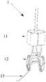
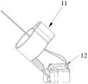
- Fig. 1Ashows a schematic diagram of a suturing device provided according to an embodiment of the present invention.
- Fig. 1Bis a schematic view from another angle of the suturing device provided according to an embodiment of the present invention.
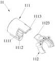
- Fig. 2Ashows a schematic diagram of a main housing of a suturing device according to an embodiment of the present invention.
- Fig. 2Bshows a schematic diagram of the first housing and the second housing in Fig. 2A after being separated.
- Fig. 2Cis a schematic view from another angle of the main housing of the suturing device provided according to an embodiment of the present invention.
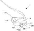
- Fig. 3Ashows a schematic diagram of a needle insertion assembly of a suture device according to an embodiment of the present invention (in which only part of the first drawstring and the second drawstring are shown).
- Fig. 3Bshows an exploded view of the needle insertion assembly of the suture device according to an embodiment of the present invention.
- Fig. 3Cis a schematic diagram showing the assembled state of the needle insertion assembly and the main housing of the suturing device according to an embodiment of the present invention.
- Fig. 4Ashows a schematic diagram of a suture needle of a suturing device according to an embodiment of the present invention.
- Fig. 4Bis a schematic view from another angle of the suture needle of the suturing device provided according to an embodiment of the present invention.
- Fig. 4Cshows a side view of the suture needle of the suturing device according to an embodiment of the present invention.
- Fig. 5Ashows an exploded view of the anti-retraction needle assembly of the suture device according to an embodiment of the present invention.
- Fig. 5Bshows a partial assembly diagram of the anti-retraction needle assembly of the suturing device according to an embodiment of the present invention.
- Fig. 5Cis a schematic diagram showing the assembled state of the anti-retraction needle assembly, the suture needle and the main housing of the suturing device according to an embodiment of the present invention.
- 6A to 6Dare schematic diagrams showing different states of the anti-retraction needle assembly, the suture needle, and the needle insertion assembly of the suturing device according to an embodiment of the present invention.
- Fig. 7Ashows a schematic diagram of an operating handle provided according to an embodiment of the present invention.
- Fig. 7Bis a schematic diagram of another angle of the operating handle provided according to an embodiment of the present invention.
- Fig. 8Ais an exploded schematic diagram of the safety switch assembly of the operating handle provided according to an embodiment of the present invention.
- Fig. 8Bis a schematic diagram of the installation of the safety switch assembly of the operating handle provided according to an embodiment of the present invention.
- Fig. 9Ashows an exploded schematic diagram of the inner ring assembly of the operating handle provided according to an embodiment of the present invention.
- Fig. 9Bis a schematic diagram of the installation of the inner ring assembly of the operating handle provided according to an embodiment of the present invention.
- Fig. 10Ashows an exploded schematic diagram of a clutch assembly of an operating handle provided according to an embodiment of the present invention.
- 10B to 10Fare schematic diagrams showing the installation of the clutch assembly of the operating handle and the front shell and the rear shell according to an embodiment of the present invention.
- FIG. 11Ashows an exploded schematic diagram of the operating rod assembly of the operating handle provided according to an embodiment of the present invention.
- 11B-11Dare schematic diagrams showing the installation of the operating rod assembly of the operating handle and the front shell and the rear shell according to an embodiment of the present invention.
- Fig. 12Ashows an exploded schematic diagram of a torque limiter assembly of an operating handle provided according to an embodiment of the present invention.
- 12B and 12Care schematic diagrams showing the installation of the torque limiter assembly of the operating handle and the front shell and the rear shell according to an embodiment of the present invention.
- Fig. 13Ais a schematic diagram showing the installation of an operating handle and an endoscope according to an embodiment of the present invention.
- FIG. 13Bis a schematic diagram showing another angle of installation of the operating handle and the endoscope according to an embodiment of the present invention.
- Fig. 15Ais a schematic diagram showing the installation of a connecting ring and an endoscope according to an embodiment of the present invention.
- Fig. 15Bis a schematic diagram showing the installation of a connecting ring, a suture device and an endoscope according to an embodiment of the present invention.
- 16A and 16Bare schematic diagrams showing the installation process of the operating handle and the endoscope according to an embodiment of the present invention.
- 17A and 17Bare schematic diagrams showing the installation process of the stapler and the endoscope according to an embodiment of the present invention.
- FIGS. 18A and 18B, FIGS. 19A-19C, FIGS. 20A and 20B, FIGS. 21A-21C, FIGS. 22A-22C, and FIGS. 23A-23Mshow schematic diagrams of the use process of the treatment system according to an embodiment of the present invention.
- Fig. 24is a schematic diagram of a snare ring of a treatment device provided according to an embodiment of the present invention.
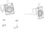
- Fig. 25is a schematic diagram of a suturing device provided by another embodiment of the present invention.
- Fig. 26is an exploded view of a suturing device provided by another embodiment of the present invention.
- the inventionprovides a suturing device, an operation handle matched with the suturing device, a treatment device composed of the suturing device and an operation handle, and a treatment system composed of the treatment device and an endoscope matched with the suturing device.
- the suturing devicecan be used to perform in vivo suturing on mammalian tissues, regardless of whether the subject is human or not and whether the subject to be sutured is alive.
- the stapler provided by the present inventioncan not only be used in conjunction with an endoscope, but also can be used in conjunction with other devices capable of realizing steering guidance.
- the present inventionprovides a stapler 1 for piercing and suturing tissue to perform surgical operations in the body.
- the suturing device 1includes a main housing 11, a needle insertion assembly 12, a suture needle 13, and an anti-retraction needle assembly 14.
- the main housing 11includes a first housing 111 and a second housing 112.
- the first housing 111may have two channels 1111, 1112 in the middle, and the first channel 1111 may be sleeved on the tip of the endoscope.
- the two channels 1112can pass the external clamp tube to fix the external clamp tube.
- the present inventiondoes not impose any limitation on this.
- the suturing deviceis used with an endoscope with a double clamp
- the first housingmay have only one channel, so that the suturing device can be sleeved on the tip of the endoscope.
- the first housingmay not have a channel, but may be fixed to the tip of the endoscope by using other structures, such as a fixing band.
- the present inventiondoes not impose any limitation on the shapes of the first housing 111 and the second housing 112.
- the outer surfaces of the first housing 111 and the second housing 112 in this embodimentare both smooth surfaces without edges or corners.
- the suturing devicedoes not affect the visual field of the tip of the endoscope as much as possible, and the tip facilitates the suturing operation in the body, and also reduces the damage caused by touching the tissues in the body.
- the outer surfaceis arc-shaped, which prevents the edges of the shell from damaging the tissues in the body during operation.
- the first housing 111has a connecting groove 1113
- the second housing 112has a connecting protrusion 1123.
- the shape and size of the connecting protrusion 1123match the shape and size of the connecting groove 1113.
- the connecting protrusion 1123is inserted into the connecting groove 1113 to connect the second housing 112 and the first housing 111 together.
- the shape of the connecting groove 1113is arc.
- the connecting groovemay have other shapes, as long as the connecting relationship between the first shell 111 and the second shell 112 is realized.
- the second housingmay have a connecting groove
- the first housingmay have a connecting protrusion.
- the connecting seam formed after the connecting groove 1113 and the connecting protrusion 1123can be welded together by laser welding.
- the present inventiondoes not impose any limitation on the fixing manner of the first housing 111 and the second housing 112.
- the main housingmay not be divided into two parts, the first housing 111 and the second housing 112, and the main housing may be formed by integral molding.
- the main housing 56is divided into two parts for production, which makes the production of each component easier, easy to standardize, and reduces production costs.
- the second housing 112has a first sliding groove 1121 and a second sliding groove 1122, and the first sliding groove 1121 and the second sliding groove 1122 are respectively located on both sides of the main body portion of the second housing 112.
- the needle insertion assembly 12is disposed on the main housing 11 and forms a detachable engagement relationship with the suture needle 13 to control the advancement of the suture needle 13, thereby performing target suture.
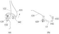
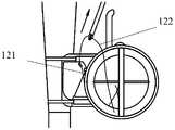
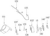
- the needle insertion assembly 12includes a first drawstring 121, a second drawstring 122, an upper shell 123, a spring 124, a needle insertion tooth 125 and a slider 126.
- the needle insertion assembly 12includes two drawstrings, a first drawstring 121 and a second drawstring 122, respectively.
- the two drawstringsare controlled to control the movement of the needle insertion assembly in different directions, the operation is simple and easy to understand, and the risk of surgical failure is greatly reduced.
- the present inventionis not limited to this.
- the needle insertion assembly 12may have only one drawstring, and the advancement of the suture needle can be controlled by the retracting and pulling of one drawstring.
- the other structure of the needle insertion assemblyis correspondingly changed, for example, through the form of gear sliding or connecting rod rotation, one pull rope can realize bidirectional control.
- the needle insertion assembly 12may not use a drawstring, and the control of the suture needle can be achieved through alternative ways of other structures.
- one end of the first pull cord 121 and the second pull cord 122has stoppers 1211 and 1221, respectively.
- the stoppers 1211 and 1221can be knots or specially made plastic blocks.
- the present inventiondoes not make any restrictions on the form and material of the stopper, as long as the diameter of the stopper is larger than the diameter of the rope body parts of the first draw rope 121 and the second draw rope 122.
- the first pull cord 121 and the second pull cord 122may not have a stopper, and one end of the first pull cord 121 and the second pull cord 122 may be fixed on the slider 126 by bonding.
- the upper shell 123has two through holes 1231 and two upper fixing holes 1232.
- the perforation 1231allows the rope body parts of the first draw rope 121 and the second draw rope 122 to pass through
- the upper fixing hole 1232allows a fixing member (such as a screw) to pass through to fix the upper shell 123 to the second shell of the main shell 11 112 on.
- the upper shell 123further has two extension parts 1233.
- the extension 1233just wraps the side surface, thereby reducing the possible damage to the internal tissues caused by the gaps or edges formed after the components and the components are assembled.
- the present inventiondoes not impose any limitation on the specific shape of the upper shell 123.
- the needle insertion tooth 125includes a tooth 1251 and a blocking member 1252.
- the top end of the tooth 1251is an inclined surface, which can be engaged with the groove of the suture needle 13 (described in detail below).
- One end of the spring 124abuts against the stopper 1252, and the other end abuts against the upper shell 123.
- the slider 126has two side holes 1261 and a middle hole 1262.
- the two side holes 1261can pass through the rope body parts of the first draw rope 121 and the second draw rope 122, but clamp the stoppers 1211, 1221 of the first draw rope 121 and the second draw rope 122, that is, the stoppers 1211 ,
- the outer diameter of 1221is greater than the inner diameter of the side hole 1261.
- the middle hole 1262can allow the tooth 1251 of the needle tooth 125 to pass through, but the stopper 1252 of the needle tooth 125 cannot pass through the middle hole 1262.
- the first pull cord 121 and the second pull cord 122respectively pass through the side hole 1261 of the slider 126 and then pass through the perforation 1231 of the upper shell 123.
- the needle insertion tooth 125is installed in the middle hole 1262 of the slider 126, and one end of the spring 124 abuts against the surface of the needle insertion tooth 125.
- the needle insertion tooth 125, the sliding block 126 and the spring 124are installed in the second sliding groove 1122 of the second housing 112 and slidable in the second sliding groove 1122, and the upper shell 123 covers the second sliding groove 1122.
- One end of the first pull cord 121 and the second pull cord 122is fixed on the sliding block 126, and the other end is fixed on the operating handle, and the needle insertion tooth 125 penetrates the sliding block 126.
- the drawstringis pulled, one end of the tooth part of the needle insertion tooth 125 is caught in the slot on the suture needle, and then the suture needle is driven to move forward, so that the needle is inserted, the needle is pulled out, and the thread is threaded.
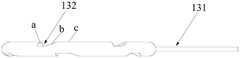
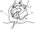
- the suture thread 131can be fixed or detachably fixed to one end of the suture needle 13, and the other end of the suture needle 13 is a pointed end, which can pierce tissue.
- the suture needle 13has four grooves 132 on one side, and three grooves 132 on the other side.
- the grooves on both sidesare arranged in a staggered manner, that is, the grooves are not completely correspondingly arranged on both sides of the same place. With this arrangement, the suture needle is not easily bent, deformed or broken.
- the present inventiondoes not impose any limitation on this.
- each slot 132has an asymmetrical structure, one side is a slope a with a larger inclination angle, which acts as a barrier, and the other side is a slope b with a smaller inclination angle, and the slope b and the top end of the tooth 1251 To match the bevel.
- the top end of the tooth 1251is inclined, and the tooth 1251 can slide out of the slot 132 through the inclined surface b under the force of the drawstring, thereby releasing the engagement relationship between the needle insertion tooth 125 and the suture needle 13.
- the angle between the bevel a of each slot 132 and one side c of the suture needle 13is 60°-90°, and the angle between the other bevel b and the side c of the suture needle 13 is 10° -45°.
- the present inventiondoes not impose any limitation on the specific degree of the inclination angle.
- the inclined surface bis not a flat surface, but an arc-shaped surface, which is more conducive for the top end of the tooth 1251 to slide out of the slot 132 to release the engagement relationship between the needle insertion tooth 125 and the slot 132.
- the suture needle 13 of this embodimentis a suture needle with thread.
- the tail of the suture needle 13has a conical depression, one end of the suture thread 131 is inserted into the conical depression, and then the tail end of the suture needle 13 is squeezed to fix the suture thread 131 at the end of the suture needle 13 .
- the suture threadmay be detachably fixed to one end of the suture needle by other means, such as a traditional needle threading method.
- the suture needle 13can be made of stainless steel, and the diameter of the cross section of the suture needle 13 can be 8mm, 10mm, 12mm, etc.
- the present inventiondoes not limit this, and a suture needle of appropriate size can be selected according to actual treatment needs.
- the length of the suture thread 131is 30 cm-60 cm, and the suture thread 131 can be polypropylene thread, nylon thread, etc.
- the present inventiondoes not impose any limitation on the length and material of the suture thread.
- bioabsorbable suturescan be used, which eliminates the need for suture removal and reduces the risk of a second operation for the patient.
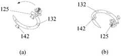
- the anti-retraction needle assembly 14is disposed on the main housing 11 and forms a detachable engagement relationship with the suture needle 13 to prevent the suture needle 13 from retreating.
- the needle insertion assembly 12 and the anti-retraction needle assembly 14are respectively located on both sides of the suture needle 13.
- the anti-retraction needle assembly 14includes a lower shell 141, anti-retraction needle teeth 142, and an elastic piece 143.
- the lower shell 141has two positioning holes 1411 and two lower fixing holes 1412.
- the two anti-removal needle teeth 142are respectively installed in the two positioning holes 1411.
- the shell 141is fixed on the second shell 112 of the main shell 11.
- the elastic piece 143also has a fixing hole for a fixing member (such as a screw) to pass through to fix the elastic piece 143 on the second housing 112 of the main housing 11.
- the suture needle 13is first placed in the first sliding groove 1121 of the second housing 112, and then the lower housing 141 equipped with the anti-removal needle teeth 142 is covered on the first sliding groove 1121, and then the elastic piece 143 and the second housing 112 are fixed.
- the top end of the anti-removal needle tooth 142can be engaged with the groove 132 of the suture needle 13.
- the top ends of the two anti-retraction needle teeth 142are set as inclined surfaces.
- the inclined surfacematches the inclination angle of the inclined surface b of the locking groove 132, so that the anti-removal needle teeth 142 can slide out of the locking groove 132 through the inclined surface b under the force of the pull rope.
- the needle insertion teeth 125 and the anti-retraction needle teeth 142are respectively located on two sides of the suture needle 13 and are respectively detachably engaged with the groove 132 of the suture needle 13.
- the detachable engagementmeans that the engagement relationship can be formed or released.
- the needle insertion teeth 125 and the anti-retraction needle teeth 142 and the suture needleare in a separable engagement relationship, so complex functions (such as suture of the target suture tissue and knotting of the suture thread) can be realized through a simple structure. It occupies small volume and low production cost.
- the present inventiondoes not make any limitation on the shape of the top end of the needle insertion tooth 125 and the anti-retraction needle tooth 142. In other embodiments, the top ends of the needle insertion teeth 125 and the anti-retraction needle teeth 142 may also be arc-shaped to facilitate sliding. As long as the inter-cooperating structure that can form an engagement relationship with the suture needle and can release the engagement relationship, the function of the present invention can be achieved, and it is also within the scope of the present invention.
- the elastic piece 143relies on its own elastic force to apply elastic pressure to the anti-retraction needle tooth 142, which can not only make the anti-retraction needle tooth 142 slide out of the slot 132 under the action of external force, but also can press the anti-retraction needle tooth 142 by the elastic force.
- the retracting teeth 142make it engage in the slot 132.
- FIGS. 6A to 6DThe left side (a) and right side (b) of each picture in Fig. 6A-Fig. 6D are the relationship between the top view and the bottom view. In order to clearly show the location of the internal parts, not all components are shown in the drawings.
- the "back” mentioned in the following descriptionis from the perspective of (a) on the left in Figure 6A-6D.
- the upper sideis defined as the front side
- the lower sideis the back side
- (a) and (b)are It is similar to the relationship of mirror image, so the back side shown in (b) is on the top.
- Figure 6Ashows the positions of the needle insertion teeth, suture needles, and anti-retraction needle teeth in the suturing device in the initial state.
- the needle insertion teeth 125 of the needle insertion assembly 12are engaged with a slot of the suture needle 13
- the engaging positionis located at the tail end of the suture needle 13, that is, the end close to the suture thread.
- One of the anti-retraction needle teeth 142 of the anti-retraction needle assembly 14(the anti-retraction needle tooth 142 on the right side as shown in FIG.
- the engagement positionis located at the top end of the suture needle 13, that is, the end close to the tip of the suture needle.
- the first drawstring 121is pulled, because the needle insertion tooth 125 is engaged in the groove 132 of the suture needle 13, and the direction of the force is to make the tip of the needle insertion tooth 125 abut against the larger inclination angle of the groove 132. side.
- the drawstring 121pulls the needle-in tooth 125, thereby driving the entire suture needle 13 to move forward in a clockwise direction as shown in FIG. 6A (a).
- the running direction of the anti-retraction needle tooth 142 relative to the suture needle 13is counterclockwise (actually, the anti-retraction needle tooth 142 does not move, but the suture needle 13 is moving clockwise), and the anti-retraction needle tooth 142 can slide through the slope of the slot 132.
- the card exit slotwill not cause any hindrance to the travel of the suture needle 13.
- the tip of the suture needle 13is exposed from the main housing 11, then the tissue to be sutured is pierced, and the suture thread is driven through the target suture tissue. After half a turn, the tip of the suture needle 13 returns to the main housing. 11 of the first chute 1121.
- each partis as shown in FIG. 6B. Since the needle insertion tooth 125 has already slid to the end of the second sliding groove 1122, it cannot move forward, and the first pull rope 121 cannot be pulled further. As for the needle insertion tooth 125, the force applied through the first pull cord 121 and the force applied through the second pull cord 122 are in opposite directions. The user then pulls the second drawstring 122, the needle insertion teeth 125 will slide out of the slot 132 through the slope of the slot 132, and then move back in the counterclockwise direction as shown in Figure 6B (a) until it returns to the beginning Location. During this process, another anti-retraction needle tooth 142 (the anti-retraction needle tooth 142 on the left as shown in FIG.
- the needle insertion tooth 125has returned to the initial position, and the second pull cord 122 cannot continue to pull the needle insertion tooth 125.
- the needle insertion tooth 125is again engaged in a groove 132 of the suture needle 13, and the engaging position is located at the end close to the tip of the suture needle.
- the anti-retraction needle tooth 142 on the left side shown in FIG. 6C (b)continues to be stuck in the groove 132 on the back of the suture needle 13, that is, the engaging position is located at the end close to the tip of the suture needle.
- the first drawstring 121is pulled, because the direction of the force is such that the top end of the needle insertion tooth 125 abuts on the side with the larger inclination of the slot 132.
- the pull rope 121pulls the needle-in tooth 125, thereby driving the entire suture needle 13 to continue to travel in a clockwise direction.
- the anti-removal needle tooth 142 that was just engagedslides out of the groove 132 through the inclined surface of the groove 132, which will not cause any hindrance to the travel of the suture needle 13.
- the needle insertion tooth 125When the needle insertion tooth 125 has slid to the end of the second chute 1122 and cannot continue to advance, the first drawstring 121 cannot be further pulled. At this time, it is located at the position shown in FIG. 6D, and the suture needle has thus completed a The march of the circle. At this time, the engagement position of the needle insertion tooth 125 and the suture needle 13 is located at the end close to the tip of the suture needle.
- the anti-retraction needle tooth 142 on the right side shown in Figure 6D (b)is engaged with the suture needle 13 ⁇ 132 ⁇ In the slot 132.
- the suture needlecan complete the suture of the target suture tissue together with the suture thread or the stitching (threading into the needle) knot thread forming action.
- the needle insertion teeth 125are alternately snapped into the slots at the top or tail of the suture needle.
- the needle insertion teeth 125 and the suture needle 13move together and also have relative movement (suture needle 13 Do not move, the needle feed tooth 125 moves).
- the anti-retraction needle tooth 142does not move, and the suture needle 13 moves relative to the anti-retraction needle tooth 142, so that the two anti-retraction needle teeth 142 alternately engage with one of the grooves 132 of the suture needle 13.
- the present inventionalso provides a method for using the suturing device, which includes the following steps:
- the method of using the suturing device provided by the present inventionincludes the following steps:
- the needle insertion teeth of the needle insertion assemblyare engaged with the locking groove of the suture needle.
- the first drawstring of the needle insertion assemblyis operated so that the suture needle and the needle insertion assembly travel forward along the chute together.
- the needle insertion assemblymoves from one end of the chute to the other end in the main housing, and the tip of the suture needle is exposed from the main housing, travels for a certain stroke (for example, half a circle) and then returns to the main housing.
- the "forward” in the "forward” mentioned in this applicationis not a straight line direction.
- frontrefers to moving in a clockwise direction
- “rear”refers to moving in a counterclockwise direction.
- frontrefers to moving in a counterclockwise direction
- “rear”refers to moving in a clockwise direction.
- the needle insertion assemblycannot continue to slide, and the first drawstring cannot continue to be pulled. Then pull the second drawstring of the needle insertion assembly to move the needle insertion assembly backwards. The needle insertion assembly moves from the other end of the chute to the beginning end in the main housing until it can no longer move.
- the anti-retraction needle assemblyis engaged with the suture needle, and the position of engagement is close to the tip of the suture needle, and the suture needle does not move under the action of the anti-retraction needle assembly during this process.
- the action of operating the needle insertion assemblyis completed by operating the operating handle.
- the needle insertion assemblybefore operating the needle insertion assembly, it further includes using a snare ring to trap the tissue at the tip of the endoscope.
- italso includes using the tip pair of the endoscope to clamp both ends of the suture thread to complete the knotting action of the suture thread.
- the present inventionalso provides a treatment device, which includes the aforementioned stapler 1 and an operating handle 6.
- a treatment devicewhich includes the aforementioned stapler 1 and an operating handle 6.
- the operating handle 6As shown in FIGS. 7A and 7B, the operating handle 6 provided in this embodiment is used in conjunction with the suturing device 1 provided in this embodiment.
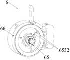
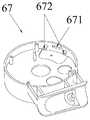
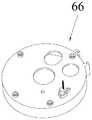
- the operating handle 6includes a safety switch assembly 61, an inner ring assembly 62, a clutch assembly 63, an operating rod assembly 64, a torque limiter assembly 65, a rear shell 66 and a front shell 67.
- the safety switch assembly 61includes a safety switch 611 and a compression spring 612.
- the compression spring 612is installed in the hole of the safety switch 611, and then installed in the safety switch groove 661 of the rear shell 66 together.
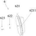
- the inner ring assembly 62includes an inner ring 621, a washer 622, and a screw 623. Insert the inner ring 621 into the middle hole 6521 of the central shaft 652, install the washer 622, and tighten it with the screw 623.
- the inner ring 621has a square hole 6211 and two tie holes 6212 (see FIG. 7A).
- the clutch assembly 63includes compression springs 631 and 632, a limiting pin 633, a screw 634, a limiting member 635, and an operating handle clutch lever 636. Put the compression spring 632 into the hole of the operating handle clutch lever 636, put it into the stopper 635, put it into the side hole 671 of the front shell 67, and put the screw 634 into the screw hole 672 and tighten it.
- the compression spring 631is installed in the limit pin 633 and installed in the square hole 662 of the rear shell 66 together.
- the operating rod assembly 64includes a tension spring 641, a transmission gear 642, an operating handle rod 643 and a gear connecting block 644.
- the tension spring 641is installed in the cylinder 674 of the front shell 67
- the transmission gear 642is installed in the In the bottom oval hole 675 of the front shell 67.
- the compression spring 631is installed in the limit pin 633 and installed in the square hole 662 of the rear shell 66 together.
- the gear connecting block 644is installed in the operating handle lever 643 and the transmission gear 642.
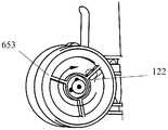
- the torque limiter assembly 65includes a grooved gear 651, a central shaft 652, an outer ring 653, a compression spring 654, and a hexagon nut 655.
- the compression spring 654 and the hexagon nut 655are aligned with the central shaft 652 and installed.
- the outer ring 653has a square hole 6531 and two tie holes 6532 (see FIG. 7B).
- the present inventionalso provides a treatment system, including the above-mentioned treatment device and the endoscope 2.
- the treatment deviceis used in conjunction with an endoscope, including an operating handle and a stapler.
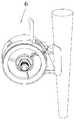
- 13A and 13Bare schematic diagrams of the operation handle 6, the first drawstring 121, and the second drawstring 122 being installed to the flexible endoscope 2.
- the first pull cord 121 and the second pull cord 122pass through the insertion jaw 23 of the soft endoscope 2, pass through the hole of the operating handle 6, and are tied to the inner ring 621 and the outer ring 653, respectively.
- the operating handle 6is installed at the position of the insertion jaw 23 of the soft endoscope 2 and fixed with handle fasteners.
- the operating principle of the operating handleis: push open the safety switch assembly 61, pull the operating handle lever 643 in the operating lever assembly 64, and transmit the force to the transmission gear 642 through the gear connecting block 644, and then to the belt in the torque limiter assembly 65
- the groove gear 651drives the outer ring 653 to rotate, thereby driving the first rope 121.
- the tension spring 641can reset the operating rod assembly 64 to achieve continuous pulling.
- the compression spring 654can limit the transmission of excessive force and disengage the grooved gear 651 from the outer ring 653, thereby protecting the first rope 121 from being broken due to excessive force.
- slide the operating handle clutch lever 635 in the clutch assembly 63to separate the limit pin 632 from the outer ring 653 until the outer ring 653 can rotate freely. Rotating the inner ring 621 in the inner ring assembly 62 drives the second drawstring 122.
- the present inventiondoes not impose any limitation on the specific structure of the operating handle. As long as the function of the operating handle of this embodiment can be realized, it can be used with the suturing device provided in this embodiment. In other embodiments, the suturing device can also be used independently instead of with the operating handle.
- the suturing devicemay have a pull loop, which is arranged at the end of the pull cord, and the pull loop is pulled to pull the pull cord.
- the operating handleincludes a spring cap 811, a screw 812, a driving wheel 813, a spring 821, an anti-retraction tooth 822, a shaft 831, a spring 832, 833, a pull rod 834, a screw 835, a button 841, a rear shell 842, a first connecting piece 851, a The second connecting piece 852, the driven wheel 86, the front shell 87, the torsion spring 881, the cover plate 882, the screw 883, the shaft 891, and the sliding block 892.
- the connection relationship between the componentscan be clearly seen in the assembly process in the figure, and will not be repeated here.
- Pulling the lever 834drives the driving wheel 813 to rotate counterclockwise.
- the spring 832resets the lever 834 to achieve reciprocating pulling, and the driving wheel 813 continues to rotate counterclockwise.
- the anti-return tooth 822is to prevent the driving wheel 813 from rotating clockwise when the lever 834 is released.
- the driving wheel 813continues to rotate counterclockwise, which will drive the driven wheel 86 to rotate together.
- the torsion spring 881drives the driven wheel 86 to rotate clockwise to reset.
- the operating handleis installed. The rotation of the driven wheel 86 will drive the slider 892 to slide along the shaft 891. Thereby driving the two drawstrings of the suture device to tighten and relax.
- the operating handle provided in this embodimentrequires only a slight force when operating, and can be operated with one hand, and can be completed with only two fingers of one hand.
- the directionis changed from multi-directional to single-directional, the volume is reduced, the production link is reduced, and the cost is reduced.
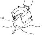
- the treatment devicemay further include a connecting ring 4.
- the connecting ring 4is made of silica gel and has elasticity.
- the present inventiondoes not impose any limitation on the material of the connecting ring.
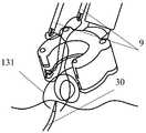
- the external forceps tube 3, the push knot tube 5, the connecting ring 4 and the suture device 1are installed on the endoscope 2.
- the external forceps tube 3is fixed to the hose portion 21 of the endoscope 2 through the connecting ring 4, and the push-knot tube 5 is installed in the inner hole of the external forceps tube 3.
- Another connecting ring 4is sleeved on the tip 22 of the endoscope 2, and the suture device 1 is sleeved on the connecting ring 4 to fix the suture device 1 to the tip 22 of the endoscope 2.
- the head end 31 of the external forceps tube 3is inserted into the stapler 1.
- the connecting ring 4 in this embodimentcan not only fix the external forceps tube 3 and the endoscope 2, but also increase the connection strength of the tip 22 of the endoscope 2, so that the suture device 1 can be firmly fixed At the tip 22 of the endoscope 2.
- multiple connecting ringscan be distributed at multiple points along the hose of the endoscope, thereby distributing the force.
- the existing treatment device of Apollo Intracorporeal Surgery Companyonly fixes the tip and the operating end, which can easily promote the passive bending of the endoscope.
- the treatment devicemay further include a snare ring 7, as shown in FIG. 24.
- the snare ring 7traps the tissue at the tip of the endoscope, or cuts the tissue through an electric current. Then, the stapler provided in this embodiment is used to stitch the target stitched tissue.
- the snare ring 7can enter through the forceps of the endoscope itself, or through the forceps external to the endoscope, which is not limited here.
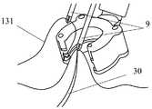
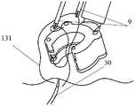
- the treatment devicemay also include a hook forceps 9 (as shown in FIG. 18B).
- the hook forceps 9performs tissue grasping action or suture hooking action at the tip of the endoscope, and finally can Clamp both ends of the suture thread to complete the knotting action of the suture thread.
- the hook forcepscan enter through the forceps of the endoscope itself, or through the forceps external to the endoscope, and there is no limitation here.
- two hook plierscan be inserted through two clamp channels at the same time to work, or only one hook pliers can be used for work.
- the front end of the hook pliersis in the shape of a pliers with hooks.
- the treatment device and treatment system provided in this embodimentcan realize various functions such as tissue cutting, suturing, and knotting.
- the treatment device and treatment system provided in this embodimentmay also include biological glue, sealing glue, stents, anastomotic nails, and anastomotic clips, so as to achieve functional diversification.
- the endoscopecan be used in conjunction with an endoscope with an end diameter of 98 mm, a clamp channel aperture ⁇ 2 mm, and a working length ⁇ 1300 mm.
- the present inventiondoes not impose any limitation on the model of the endoscope.
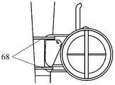
- the operating handle 6is installed at the operating end of the endoscope 2, and the operating handle 6 and the endoscope 2 are firmly fixed together by the handle fastener 68.
- the handle fastener 68is in the shape of a belt, and the operating handle 6 and the endoscope 2 are fastened by wrapping the belt around the endoscope 2.
- the present inventiondoes not impose any limitation on the shape of the handle fastener 68, as long as the component can realize the fixing function, it can be used as the handle fastener.
- the connecting ring 4is sleeved on the tip 22 of the endoscope 2, and the suture device 1 is sleeved on the connecting ring 4 at the tip 22 of the endoscope 2.
- the endoscope 2is turned on, and under the monitor, adjust the direction of the suturing device 1 so that the C-shaped opening faces downward.
- the suture device 1is tightened until the loop step surface of the suture device 1 abuts against the tip 22 of the endoscope 2.
- first drawstring and the second drawstringmay be exactly the same, and the operator can distinguish them.
- first drawstring and the second drawstringmay be identified by means of material, color, etc. for easy distinction.
- the square hole 6211 of the inner ring 621 of the operating handle 6is aligned with the side hole 671 of the front case.
- the first drawstring 121 that has been pulled out of the insertion jaw 23is inserted into the square hole 6211 of the operating handle, and then tied tightly through the two tie holes 6212 on the wing of the inner ring 621).
- the inner ringrotates clockwise to loosen the thread of the first pull cord 121 on the outside of the operating handle and wind it into the circular groove of the inner ring 621.
- the hook forceps 9is inserted again from the insertion jaw 23 of the endoscope 2, and reaches the tip of the endoscope 2 through the forceps, and then the second drawstring 122 of the stapler is clamped. Pull the second drawstring 122 near the tip into the clamp channel. Then take out the hook pliers 9 and pull it out from the inserting jaws, so that one end of the second pull cord 122 is taken out from the inserting jaws.
- the endoscope 2may be a single clamp channel endoscope.
- an external clamp tube 10is installed on the endoscope 2 first.
- the front end of the external forceps tube 10is inserted into the second channel 1112 of the edge of the first housing of the stapler until it abuts on the step surface 1114 of the second channel 1112.
- a plurality of connecting ringsare distributed along the direction of the forceps, and the external forceps tube 10 and the hose part of the endoscope 2 are fastened by the connecting rings. Insert the push-knot tube 20 into the external clamp tube 10.
- the endoscopemay be a dual clamp channel endoscope. At this time, there is no need to install an external clamp pipe. Because the endoscope has two clamp channels, only the push-knot tube needs to be inserted into the vacant clamp channels.
- the hook forceps 9is inserted from the insertion jaw of the endoscope, and reaches the tip of the endoscope through the forceps path, and then the suture 131 is found and clamped. Insert another hook clamp 9 into the knotting tube, reach the tip of the endoscope, clamp the edge of the target suture tissue 30, and back away so that the target suture tissue 30 is in the middle of the C-shaped opening of the suture device (in the figure) The two drawstrings are omitted and not drawn). As shown in Figs. 23B and 23C, the handle lever 643 is continuously pulled back to allow the suture needle to pass through the tissue. The depth of suture (full-thickness or stratification) depends on the wound or non-invasive tissue treatment.
- the pull rod 643is stopped to pull back. Then gently lift the knob of the inner ring 621 of the operating handle to pull out about 3 mm, while rotating clockwise to tighten the second pull cord 122. Pull back the operating handle lever 643 to rotate the suture needle 13 into the first chute by 180° and return to the initial position. Then gently lift the knob of the inner ring 621 of the operating handle to pull out about 3 mm, and at the same time rotate it clockwise to tighten the second pull cord 122.
- the hook clamp 9 in the built-in clampchannel hooks the suture thread 131 at the tip (near the suture needle), and moderately pulls the suture thread 131 through the tissue.
- the hook clamp 9 in the other pusher tubeclamps the end of the suture 131, and adjusts the position of the suture on the endoscope 2 so that the end of the suture 131 is in the C-shaped opening of the suture. Inside, make the head end of the suture thread 131 outside the C-shaped opening of the suture device.
- FIGs. 25 and 26another embodiment of the present invention provides a suturing device.
- the structure of the suturing device 1'provided in this embodimentis basically the same as that of the suturing device 1 provided in the previous embodiment. Elements that are the same as those in the previous embodiment have the same numbers, and only the differences are described below.
- the components of the suturing device 1'of this embodimentare connected by laser welding, so the setting of screws and lugs is omitted, the number of parts of the device is saved, the production cost is reduced, and the assembly time is saved.
- the upper shell 123' of the suture device provided in this embodimentdoes not need to be provided with two upper fixing holes 1232, the lower shell 141' does not need to be provided with two lower fixing holes, and the elastic sheet 143' does not need to be provided with fixing holes, therefore There is also no need to provide three corresponding screw holes on the second housing 112'.
- the "hole” mentioned in the present inventionis not necessarily circular, but can be square, elliptical, etc., all of which fall within the scope of the "hole” to be expressed in the present invention.
- the "first” and “second” mentioned in the present inventionare only used for distinguishing and naming convenience, and do not mean that the first and the second must exist at the same time.
- the “upper” and “lower” in the present inventionare relative orientations without any limitation.
- the stapler, treatment device and treatment system of the present inventioncan be used for natural cavity surgery (non-invasive surgery), minimally invasive surgery or pioneering surgery.
- the structureis simple, the production cost is low, the advancement of the suture needle can be controlled only by the needle insertion component, so that intermittent suture or continuous suture can be performed in the soft tissue, the operation is simple, and the risk of operation failure is greatly reduced.
- the suturing device of the present inventionfurther includes an anti-retraction needle assembly, so that continuous advancement of the suture needle is possible.
- the needle insertion component and the anti-retraction needle component of the present invention and the suture needleare in a separable engagement relationship, so complex functions (such as the suturing of the target suture tissue and the knotting of the suture thread) can be realized through a simple structure. ), the suturing device occupies a small volume and the production cost is low.
- a rotary drilling devicemust be used throughout the entire process to achieve the suture function, and the existing rotary drilling device directly hooks the tissue and then pulls it up.
- the invented suturing devicecan independently realize the suture function without using the rotary drilling and hooking device during the suturing process, avoiding the damage to the tissue by the rotary drilling and hooking device, and greatly reducing the operation risk.
Landscapes
- Health & Medical Sciences (AREA)
- Life Sciences & Earth Sciences (AREA)
- Surgery (AREA)
- Nuclear Medicine, Radiotherapy & Molecular Imaging (AREA)
- Molecular Biology (AREA)
- Veterinary Medicine (AREA)
- Public Health (AREA)
- General Health & Medical Sciences (AREA)
- Animal Behavior & Ethology (AREA)
- Engineering & Computer Science (AREA)
- Biomedical Technology (AREA)
- Heart & Thoracic Surgery (AREA)
- Medical Informatics (AREA)
- Physics & Mathematics (AREA)
- Biophysics (AREA)
- Radiology & Medical Imaging (AREA)
- Pathology (AREA)
- Optics & Photonics (AREA)
- Surgical Instruments (AREA)
Abstract
Description
Translated fromChinese本发明涉及一种治疗装置,尤其涉及一种缝合器、具有缝合器的治疗装置以及治疗系统。The invention relates to a treatment device, in particular to a stapler, a treatment device with the stapler, and a treatment system.
随着科技的进步,手术已经从传统的开创手术,微创手术向无创手术发展。无创手术通过人体自然腔道(譬如人的食管、直肠、子宫等)进入手术区,没有外部创口,出血少,不仅减少病人生理和心理创伤,也减轻麻醉深度,大大降低麻醉带来的风险。无创手术能够有效减少术后并发症,更有利于风险较大的患者。With the advancement of technology, surgery has evolved from traditional pioneering surgery, minimally invasive surgery to non-invasive surgery. Non-invasive surgery enters the operation area through the human body's natural cavity (such as human esophagus, rectum, uterus, etc.) without external wounds and less bleeding. It not only reduces the patient's physical and psychological trauma, but also reduces the depth of anesthesia and greatly reduces the risk of anesthesia. Non-invasive surgery can effectively reduce postoperative complications and is more beneficial to patients with higher risks.
由于无创手术是近几年才开始成熟,对应配套的设备较为稀缺。特别是在体内手术后,如需要进行体内伤口组织缝合,现有大多数医疗设备无法做到。美国专利号US 7344545公开了一种用于外科手术的内窥镜缝合系统,在体外操作,于体内缝合,从而达到治疗的目的。此缝合系统包括具有第一和第二臂的组件和针回收构件,针回收构件需要与弯针臂刚性对准。组织抓持臂和针回收构件的布置使得系统体积庞大,从而使其难以在内窥镜手术中实际应用。Since non-invasive surgery has only begun to mature in recent years, the corresponding supporting equipment is relatively scarce. Especially after surgery in the body, if it is necessary to suture the wound tissue in the body, most of the existing medical equipment cannot do it. US Patent No. US7344545 discloses an endoscopic suture system for surgical operations, which operates outside the body and sutures inside the body to achieve the purpose of treatment. This suturing system includes an assembly with first and second arms and a needle recovery member, which needs to be rigidly aligned with the curved needle arm. The arrangement of the tissue grasping arm and the needle recovery member makes the system bulky, making it difficult for practical application in endoscopic surgery.
阿波罗体内手术公司也公开了一种内窥镜缝合系统。可以配合内窥镜或其他可转向引导的装置通过人体自然腔道,将缝合器装置插入身体内。该系统结构复杂,设备零件众多,制作复杂,成本高昂。该系统在使用时,需要同时占用3个钳道,由于体内手术最多只有3个钳道,因此操作过程中需要在一个钳道中交换操作装置(将原先占用一个钳道的装置取出再插入新的装置),缝合步骤繁琐。Apollo Intracorporeal Surgery has also disclosed an endoscopic suture system. It can be used with an endoscope or other steering-guided devices to insert the stapler device into the body through the natural cavity of the human body. The system has a complex structure, numerous equipment parts, complex production, and high cost. When the system is in use, it needs to occupy 3 clamp channels at the same time. Since there are only 3 clamp channels in the body operation, the operation device needs to be exchanged in one clamp channel during the operation (remove the device that originally occupied one clamp channel and insert the new one. Device), the stitching steps are cumbersome.
特别地,阿波罗体内手术公司提供的缝合装置在体内进行伤口组织缝合时,需要搭配专门的旋钻勾取装置穿刺组织后将组织勾起,然后缝合针才能够穿透组织进行缝合操作。每一圈缝合都需要进行这个操作。这个穿刺动作大大增加了手术风险,因为在体外很难准确判断体内的穿刺深度。当这个手术是缩胃手术时,这个旋钻勾取装置将有可能造成腔外组织的损伤,大大增加了患者的手术风险。In particular, when the suture device provided by Apollo Intracorporeal Surgery Company is used to suture wound tissue in the body, it needs to be equipped with a special rotary drill hook device to pierce the tissue and hook the tissue, and then the suture needle can penetrate the tissue for the suture operation. This operation is required for each stitch of stitches. This puncture action greatly increases the risk of surgery, because it is difficult to accurately determine the puncture depth in the body outside the body. When this operation is a gastric contraction operation, the rotary drill hooking device may cause damage to the tissue outside the cavity, which greatly increases the patient's surgical risk.
并且,阿波罗体内手术公司提供的缝合装置在缝合完成后,无法在不借助其他装置的情况下实现缝合线的打结操作。因此,该缝合装置在进行缝合线的 打结时,必须搭配专门的线结器。在实际操作中,将原先占用一个钳道的装置取出,然后使用装置插入钳道将线结器送入体内,之后切割缝合线,直接将线结器遗留在手术患者的体内。打结操作不仅麻烦,且将非人体的硬性物体遗留在人体内,易造成术后风险。Moreover, the suture device provided by Apollo Intracorporeal Surgery Company cannot realize the knotting operation of the suture without the aid of other devices after the suture is completed. Therefore, when the suture device is used for knotting the suture, it must be equipped with a special knotter. In actual operation, the device that originally occupies a clamp channel is taken out, and then the device is inserted into the clamp channel to send the stitching device into the body, and then the suture is cut, and the stitching device is directly left in the body of the surgical patient. The knotting operation is not only troublesome, but also leaves non-human hard objects in the human body, which is likely to cause postoperative risks.
另外,现有的软式内窥镜下的创口闭合、组织缝合以及消化道支架的固定,所面临的问题还分别有:有些器械的尺寸偏大、材质不适宜,极易损伤消化道粘膜;有些器械,一个动作分解为多个步骤操作、人工使用多个部件完成、多次交换辅助器械导致动作频繁、差错可能,有些部件还需退镜才能替换,退镜之后又得二次进镜更致操作重复与损伤可能加倍,且手术过程延长;固定夹尺寸非无级可变(仅单一几个尺寸),过多夹齿即过多损伤组织,非钳道置入的固定夹又难以不遮挡内窥镜视野;夹闭时有创缘撕裂,尤其是纤维化组织或瘢痕组织难以闭合,固定的夹闭方式也时致组织对合不佳或闭合过紧;缝合范围(大创面或小创面)或缝合深度(全层或分层)极难普适或随机调适;夹的过浅易脱落、过深易穿孔,腹部用力还需防硬物损伤;过度、过深夹闭(极难准确客观掌控深度),有可能损伤或闭合腔外器官;软性内窥镜无支撑(不像硬性的腹腔镜有支撑)难以直接打结,打结张力不易随机掌控;术后,肉芽组织过多增生,或闭合不全、术后漏;术后再出血或缺血坏死,以致二次手术(甚至开腹);部件繁多、装配耗时,成本昂贵。In addition, the existing soft endoscopes for wound closure, tissue suture, and digestive tract stent fixation are also faced with the following problems: some instruments are too large in size and inappropriate in materials, which can easily damage the digestive tract mucosa; For some instruments, one action is broken down into multiple steps, multiple parts are used manually to complete, and multiple exchanges of auxiliary instruments lead to frequent actions and possible errors. Some parts need to be removed to replace the lens. The operation repetition and damage may be doubled, and the operation process may be prolonged; the size of the clamp is not steplessly variable (only a few sizes), too many teeth means too much damage to the tissue, and it is difficult to avoid the clamp inserted without the clamp. Obstruct the vision of the endoscope; the wound edge tears during clipping, especially the fibrotic tissue or scar tissue is difficult to close, and the fixed clipping method sometimes causes the tissue to be poorly aligned or closed too tightly; the range of suture (large wound or Small wounds) or the depth of suture (full-thickness or stratification) is extremely difficult to universally or randomly adjust; if the clip is too shallow, it is easy to fall off, if it is too deep, it is easy to perforate; Accurate and objective control of depth), it is possible to damage or close extraluminal organs; soft endoscopes have no support (unlike rigid laparoscopes). More hyperplasia, or incomplete closure, postoperative leakage; postoperative bleeding or ischemic necrosis, resulting in a second operation (even laparotomy); numerous parts, time-consuming assembly, and expensive.
发明内容Summary of the invention
本发明为了克服现有技术中的至少一个不足,提供一种缝合器、具有缝合器的治疗装置以及治疗系统。In order to overcome at least one of the shortcomings in the prior art, the present invention provides a stapler, a treatment device with the stapler, and a treatment system.
于一方面,本发明提供一种缝合器,包括主壳体、缝合针、进针组件以及防退针组件。带线缝合针的一端连接有缝合线,另一端为尖端。进针组件设置于主壳体上且和缝合针形成可分离的卡合关系以控制缝合针的前进。防退针组件设置于主壳体上且和缝合针形成可分离的卡合关系从而防止缝合针的后退。In one aspect, the present invention provides a suturing device, including a main housing, a suture needle, a needle insertion assembly, and an anti-retraction needle assembly. One end of the threaded suture needle is connected with a suture thread, and the other end is a pointed end. The needle insertion component is arranged on the main housing and forms a detachable engagement relationship with the suture needle to control the advancement of the suture needle. The anti-retraction needle assembly is arranged on the main housing and forms a detachable engagement relationship with the suture needle to prevent the suture needle from retreating.
根据本发明的一实施例,进针组件包括两根拉绳,一根拉绳控制进针组件的前进从而带动缝合针的前进,另一根拉绳控制进针组件的后退。According to an embodiment of the present invention, the needle insertion assembly includes two drawstrings, one drawstring controls the advancement of the needle insertion assembly so as to drive the advancement of the suture needle, and the other drawstring controls the retreat of the needle insertion assembly.
根据本发明的一实施例,进针组件包括拉绳、上壳、弹簧、进针齿以及滑块,拉绳分别穿过滑块和上壳,进针齿安装于滑块内,弹簧的一端抵靠在进针齿的表面,进针齿、滑块以及弹簧安装于主壳体的滑槽中,上壳盖合于滑槽上。According to an embodiment of the present invention, the needle insertion assembly includes a drawstring, an upper shell, a spring, needle insertion teeth, and a slider. The drawstring passes through the slider and the upper shell respectively. The needle insertion teeth are installed in the slider. One end of the spring Abutting against the surface of the needle insertion tooth, the needle insertion tooth, the sliding block and the spring are installed in the sliding groove of the main housing, and the upper shell is closed on the sliding groove.
根据本发明的一实施例,防退针组件包括防退针齿、下壳以及弹片,防退针齿安装于下壳,防退针齿和下壳安装于主壳体的滑槽,下壳和弹片固定于主壳体。According to an embodiment of the present invention, the anti-retraction needle assembly includes anti-retraction needle teeth, a lower shell, and an elastic piece. And the shrapnel are fixed to the main housing.
根据本发明的一实施例,主壳体包括第一壳体和第二壳体,第一壳体具有连接槽,第二壳体具有连接凸起,连接凸起插入到连接槽内以使第一壳体和第二壳体连接在一起。According to an embodiment of the present invention, the main housing includes a first housing and a second housing, the first housing has a connecting groove, the second housing has a connecting protrusion, and the connecting protrusion is inserted into the connecting groove to make the first A shell and a second shell are connected together.
于另一方面,本发明还提供一种治疗装置,包括操作手柄和缝合器。缝合器固定于内窥镜的先端,缝合器包括主壳体、缝合针、进针组件以及防退针组件。带线缝合针的一端连接有缝合线,另一端为尖端。进针组件设置于主壳体上且和缝合针形成可分离的卡合关系以控制缝合针的前进。防退针组件设置于主壳体上且和缝合针形成可分离的卡合关系从而防止缝合针的后退。操作手柄固定于内窥镜的操作端,操作手柄控制进针组件从而控制缝合针的前进。In another aspect, the present invention also provides a treatment device including an operating handle and a stapler. The suturing device is fixed at the tip of the endoscope, and the suturing device includes a main housing, a suture needle, a needle insertion component, and an anti-retraction needle component. One end of the threaded suture needle is connected with a suture thread, and the other end is a pointed end. The needle insertion component is arranged on the main housing and forms a detachable engagement relationship with the suture needle to control the advancement of the suture needle. The anti-retraction needle assembly is arranged on the main housing and forms a detachable engagement relationship with the suture needle to prevent the suture needle from retreating. The operating handle is fixed on the operating end of the endoscope, and the operating handle controls the needle insertion assembly to control the advancement of the suture needle.
根据本发明的一实施例,操作手柄包括保险开关组件、内圆环组件、离合组件、操作杆组件以及扭力限制器组件。According to an embodiment of the present invention, the operating handle includes a safety switch assembly, an inner ring assembly, a clutch assembly, an operating rod assembly, and a torque limiter assembly.
根据本发明的一实施例,治疗装置还包括连接环,连接环套设于内窥镜上。According to an embodiment of the present invention, the treatment device further includes a connecting ring, and the connecting ring is sleeved on the endoscope.
根据本发明的一实施例,治疗装置还包括圈套环,圈套环在内窥镜的先端处进行组织的切割动作。According to an embodiment of the present invention, the treatment device further includes a snare ring, which performs a tissue cutting action at the tip of the endoscope.
根据本发明的一实施例,治疗装置还包括钩钳器,钩钳器在内窥镜的先端处进行组织的钳取动作或者缝合线的勾拉动作。According to an embodiment of the present invention, the treatment device further includes a hook forceps, which performs tissue grasping action or suture pulling action at the tip of the endoscope.
于另一方面,本发明还提供一种治疗系统,包括内窥镜和治疗装置。治疗装置与内窥镜配合使用,包括操作手柄和缝合器。缝合器固定于内窥镜的先端,缝合器包括主壳体、缝合针、进针组件以及防退针组件。缝合针的一端连接有缝合线,另一端为尖端。进针组件设置于主壳体上且和缝合针形成可分离的卡合关系以控制缝合针的前进。防退针组件设置于主壳体上且和缝合针形成可分离的卡合关系从而防止缝合针的后退。操作手柄固定于内窥镜的操作端,操作手柄控制进针组件从而控制缝合针的前进。操作手柄固定于内窥镜的操作端,操作手柄控制进针组件从而控制缝合针的前进。。In another aspect, the present invention also provides a treatment system, including an endoscope and a treatment device. The treatment device is used in conjunction with an endoscope, including an operating handle and a stapler. The suturing device is fixed at the tip of the endoscope, and the suturing device includes a main housing, a suture needle, a needle insertion component, and an anti-retraction needle component. One end of the suture needle is connected with a suture thread, and the other end is a tip. The needle insertion component is arranged on the main housing and forms a detachable engagement relationship with the suture needle to control the advancement of the suture needle. The anti-retraction needle assembly is arranged on the main housing and forms a detachable engagement relationship with the suture needle to prevent the suture needle from retreating. The operating handle is fixed on the operating end of the endoscope, and the operating handle controls the needle insertion assembly to control the advancement of the suture needle. The operating handle is fixed on the operating end of the endoscope, and the operating handle controls the needle insertion assembly to control the advancement of the suture needle. .
根据本发明的一实施例,治疗装置还包括连接环,连接环套设于内窥镜上。According to an embodiment of the present invention, the treatment device further includes a connecting ring, and the connecting ring is sleeved on the endoscope.
根据本发明的一实施例,治疗装置还包括圈套环,圈套环在内窥镜的先端处进行组织的切割动作。According to an embodiment of the present invention, the treatment device further includes a snare ring, which performs a tissue cutting action at the tip of the endoscope.
根据本发明的一实施例,治疗装置还包括钩钳器,钩钳器在内窥镜的先端处进行组织的钳取动作或者缝合线的勾拉动作。According to an embodiment of the present invention, the treatment device further includes a hook forceps, which performs tissue grasping action or suture pulling action at the tip of the endoscope.
于另一方面,本发明还提供一种缝合器的使用方法,包括如下步骤:In another aspect, the present invention also provides a method of using a suturing device, which includes the following steps:
操作进针组件,使得缝合针和进针组件一起向前行进,此时缝合针的尖端从主壳体中露出,行进一段行程后回到主壳体内;Operate the needle insertion assembly to make the suture needle and the needle insertion assembly move forward together. At this time, the tip of the suture needle is exposed from the main housing and returns to the main housing after a certain stroke;
操作进针组件,使得进针组件向后移动直到卡合于缝合针,此时卡合的位置靠近缝合针的尖端,缝合针在防退针组件的作用下不动;Operate the needle insertion assembly to move the needle insertion assembly backwards until it engages with the suture needle. At this time, the engagement position is close to the tip of the suture needle, and the suture needle does not move under the action of the anti-retraction needle assembly;
操作进针组件,使得缝合针和进针组件一起向前行进,直到缝合针的尖端准备从主壳体中露出;Operate the needle insertion assembly so that the suture needle and the needle insertion assembly travel forward together until the tip of the suture needle is ready to be exposed from the main housing;
操作进针组件,使得防退针组件向后移动直到卡合于缝合针,此时卡合的位置靠近缝合针带有缝合线的一端,缝合针在防退针组件的作用下不动;Operate the needle insertion assembly to move the anti-retraction needle assembly backwards until it engages with the suture needle. At this time, the position of engagement is close to the end of the suture needle with the suture thread, and the suture needle does not move under the action of the anti-retraction needle assembly;
重复上述四个步骤从而进行目标缝合组织(比如伤口组织等)的缝合或者缝线的打结操作。Repeat the above four steps to perform the operation of suturing the target suture tissue (such as wound tissue, etc.) or knotting the suture.
根据本发明的一实施例,进针组件包括第一拉绳和第二拉绳,上述四个步骤分别对应为拉动第一拉绳、拉动第二拉绳、拉动第一拉绳以及拉动第二拉绳。According to an embodiment of the present invention, the needle insertion assembly includes a first drawstring and a second drawstring. The above four steps respectively correspond to pulling the first drawstring, pulling the second drawstring, pulling the first drawstring, and pulling the second drawstring. Draw the rope.
根据本发明的一实施例,操作进针组件的动作是通过操作操作手柄来完成。According to an embodiment of the present invention, the action of operating the needle insertion assembly is completed by operating the operating handle.
根据本发明的一实施例,在操作进针组件之前,还包括用圈套环在内窥镜的先端对组织进行圈割。According to an embodiment of the present invention, before operating the needle insertion assembly, the method further includes using a snare ring to cut tissue at the tip of the endoscope.
根据本发明的一实施例,在上述所有步骤完成之后,还包括用钩钳器在内窥镜的先端对钳住缝合线的两端从而完成缝合线的打结动作。According to an embodiment of the present invention, after all the above-mentioned steps are completed, it further includes using a hook clamp to clamp both ends of the suture with the tip pair of the endoscope to complete the knotting action of the suture.
综上所述,本发明的缝合器、治疗装置和治疗系统可用于自然腔道手术(无创手术)、微创手术或开创手术。其结构简单,制作成本低,仅需通过进针组件即可控制缝合针的前进,从而在软组织中进行间断缝合或连续缝合,操作简单,大幅度降低手术失败风险。另外,本发明的缝合器还包括防退针组件,使得缝合针的连续前进实现可能。特别地,本发明的进针组件和防退针组件与缝合针都是可分离的卡合关系,因此通过简单的结构即可实现复杂的功能(例如目标缝合组织的缝合与缝合线的打结),缝合器占用体积小,制作成本低。现有技术中如果需要体外操作体内组织的缝合,必须全程配套采用旋钻勾取装置才能实现缝合功能,并且现有的旋钻勾取装置是直接对组织进行旋钻勾住然后拉起,本发明的缝合器在缝合的过程当中无需采用旋钻勾取装置,即可独立实现缝合功能,避免了旋钻勾取装置对组织的损伤,大大降低了手术风险。In summary, the stapler, treatment device and treatment system of the present invention can be used for natural cavity surgery (non-invasive surgery), minimally invasive surgery or pioneering surgery. The structure is simple, the production cost is low, the advancement of the suture needle can be controlled only by the needle insertion component, so that intermittent suture or continuous suture can be performed in the soft tissue, the operation is simple, and the risk of operation failure is greatly reduced. In addition, the suturing device of the present invention further includes an anti-retraction needle assembly, so that continuous advancement of the suture needle is possible. In particular, the needle insertion component and the anti-retraction needle component of the present invention and the suture needle are in a separable engagement relationship, so complex functions (such as the suturing of the target suture tissue and the knotting of the suture thread) can be realized through a simple structure. ), the suturing device occupies a small volume and the production cost is low. In the prior art, if it is necessary to operate the suturing of internal tissues outside the body, a rotary drill hooking device must be used throughout the entire process to achieve the suture function, and the existing rotary drill hooking device directly hooks the tissue and then pulls it up. The invented suturing device can independently realize the suture function without using the rotary drilling and hooking device during the suturing process, avoiding the damage to the tissue by the rotary drilling and hooking device, and greatly reducing the operation risk.
另外,于一实施例中,进针组件可包括两根拉绳,分别控制两根拉绳来控制进针组件不同方向的移动,操作简单明了,大幅度降低手术失败风险。于一实施例中,本发明的治疗装置和治疗系统还可包括圈套环和钩钳器,搭配缝合 器一起,能够实现组织的切割、缝合、打结等多样功能。于一实施例中,本发明的治疗装置和治疗系统还可包括连接环,当使用外置钳道管时,连接环可将外置钳道管和内窥镜固定在一起,并且沿着内窥镜的软管进行多点分布,从而分散受力。现有的阿波罗体内手术公司的治疗装置,仅先端和操作端进行固定,极易造成内窥镜被动弯曲。In addition, in one embodiment, the needle insertion assembly may include two drawstrings, which are respectively controlled to control the movement of the needle insertion assembly in different directions, the operation is simple and clear, and the risk of operation failure is greatly reduced. In one embodiment, the treatment device and treatment system of the present invention may further include a snare loop and a hook clamp, which, together with the suture device, can realize various functions such as tissue cutting, suturing, and knotting. In one embodiment, the treatment device and treatment system of the present invention may further include a connecting ring. When the external forceps tube is used, the connecting ring can fix the external forceps tube and the endoscope together and run along the inner The hose of the speculum is distributed at multiple points to distribute the force. The existing treatment device of Apollo Intracorporeal Surgery Company only fixes the tip and the operating end, which can easily cause the endoscope to bend passively.
特别地,本发明提供的缝合器、治疗装置和治疗系统在目标缝合组织缝合完毕后,可按接近开创手术打结习惯的操作进行打结。一直以来,在体内进行打结操作是个大难题,因为在体外向体内施加的力只能是往上的,这样目标缝合组织会被拉动,如果力度太大,会对组织造成损伤,力度太小,则打的结不紧,如果组织发生运动,很可能线结松散,需重新缝合。本发明提供的缝合器、治疗装置和治疗系统在进行打结时,是与缝合进行类似的简捷操作,由缝合针引导缝合线构成“结”,最后通过钩钳器将两端缝合线拉紧,打结时施加的力是水平或接近水平的。这样线结松紧适度、创面对合准确,且使得操作简单、手术难度降低,不遗留任何夹具在人体内,克服了现有技术中打结难的难题。可适用于不同范围创面或组织的闭合与缝合、可择需选择分层或全层缝合。In particular, the stapler, treatment device and treatment system provided by the present invention can be knotted according to an operation that is close to creating a knotting habit of surgery after the target sutured tissue is sutured. It has always been a big problem to tie knots in the body, because the force applied to the body outside the body can only be upwards, so the target suture tissue will be pulled. If the force is too strong, it will cause damage to the tissue, and the force is too small. , The knot is not tight. If the tissue moves, it is likely that the knot is loose and needs to be re-sutured. The suture device, treatment device and treatment system provided by the present invention perform a simple and convenient operation similar to suture when knotting. The suture needle guides the suture to form a "knot", and finally the suture at both ends is tightened by the hook clamp , The force applied when knotting is horizontal or close to horizontal. In this way, the tightness of the thread is moderate, the wound surface is accurate, and the operation is simple, and the difficulty of the operation is reduced, and no clamp is left in the human body, which overcomes the difficulty of knotting in the prior art. It can be applied to the closure and suture of wounds or tissues in different scopes, and can choose layered or full-thickness suture as needed.
为让本发明的上述和其它目的、特征和优点能更明显易懂,下文特举较佳实施例,并配合附图,作详细说明如下。In order to make the above-mentioned and other objects, features and advantages of the present invention more obvious and understandable, the following describes the preferred embodiments in conjunction with the accompanying drawings in detail.
图1A所示为根据本发明一实施例提供的缝合器的示意图。Fig. 1A shows a schematic diagram of a suturing device provided according to an embodiment of the present invention.
图1B所示为根据本发明一实施例提供的缝合器的另一角度示意图。Fig. 1B is a schematic view from another angle of the suturing device provided according to an embodiment of the present invention.
图2A所示为根据本发明一实施例提供的缝合器的主壳体的示意图。Fig. 2A shows a schematic diagram of a main housing of a suturing device according to an embodiment of the present invention.
图2B所示为图2A中第一壳体和第二壳体分离后的示意图。Fig. 2B shows a schematic diagram of the first housing and the second housing in Fig. 2A after being separated.
图2C所示为根据本发明一实施例提供的缝合器的主壳体的另一角度示意图。Fig. 2C is a schematic view from another angle of the main housing of the suturing device provided according to an embodiment of the present invention.
图3A所示为根据本发明一实施例提供的缝合器的进针组件的示意图(其中第一拉绳和第二拉绳仅显示出部分)。Fig. 3A shows a schematic diagram of a needle insertion assembly of a suture device according to an embodiment of the present invention (in which only part of the first drawstring and the second drawstring are shown).
图3B所示为根据本发明一实施例提供的缝合器的进针组件的爆炸图。Fig. 3B shows an exploded view of the needle insertion assembly of the suture device according to an embodiment of the present invention.
图3C所示为根据本发明一实施例提供的缝合器的进针组件和主壳体的组装状态示意图。Fig. 3C is a schematic diagram showing the assembled state of the needle insertion assembly and the main housing of the suturing device according to an embodiment of the present invention.
图4A所示为根据本发明一实施例提供的缝合器的缝合针的示意图。Fig. 4A shows a schematic diagram of a suture needle of a suturing device according to an embodiment of the present invention.
图4B所示为根据本发明一实施例提供的缝合器的缝合针的另一角度示意图。Fig. 4B is a schematic view from another angle of the suture needle of the suturing device provided according to an embodiment of the present invention.
图4C所示为根据本发明一实施例提供的缝合器的缝合针的侧视图。Fig. 4C shows a side view of the suture needle of the suturing device according to an embodiment of the present invention.
图5A所示为根据本发明一实施例提供的缝合器的防退针组件的爆炸图。Fig. 5A shows an exploded view of the anti-retraction needle assembly of the suture device according to an embodiment of the present invention.
图5B所示为根据本发明一实施例提供的缝合器的防退针组件的部分组装示意图。Fig. 5B shows a partial assembly diagram of the anti-retraction needle assembly of the suturing device according to an embodiment of the present invention.
图5C所示为根据本发明一实施例提供的缝合器的防退针组件、缝合针和主壳体的组装状态示意图。Fig. 5C is a schematic diagram showing the assembled state of the anti-retraction needle assembly, the suture needle and the main housing of the suturing device according to an embodiment of the present invention.
图6A-图6D所示为根据本发明一实施例提供的缝合器的防退针组件、缝合针和进针组件在作动过程中不同状态的示意图。6A to 6D are schematic diagrams showing different states of the anti-retraction needle assembly, the suture needle, and the needle insertion assembly of the suturing device according to an embodiment of the present invention.
图7A所示为根据本发明一实施例提供的操作手柄的示意图。Fig. 7A shows a schematic diagram of an operating handle provided according to an embodiment of the present invention.
图7B所示为根据本发明一实施例提供的操作手柄的另一角度示意图。Fig. 7B is a schematic diagram of another angle of the operating handle provided according to an embodiment of the present invention.
图8A所示为根据本发明一实施例提供的操作手柄的保险开关组件的爆炸示意图。Fig. 8A is an exploded schematic diagram of the safety switch assembly of the operating handle provided according to an embodiment of the present invention.
图8B所示为根据本发明一实施例提供的操作手柄的保险开关组件的安装示意图。Fig. 8B is a schematic diagram of the installation of the safety switch assembly of the operating handle provided according to an embodiment of the present invention.
图9A所示为根据本发明一实施例提供的操作手柄的内圆环组件的爆炸示意图。Fig. 9A shows an exploded schematic diagram of the inner ring assembly of the operating handle provided according to an embodiment of the present invention.
图9B所示为根据本发明一实施例提供的操作手柄的内圆环组件的安装示意图。Fig. 9B is a schematic diagram of the installation of the inner ring assembly of the operating handle provided according to an embodiment of the present invention.
图10A所示为根据本发明一实施例提供的操作手柄的离合组件的爆炸示意图。Fig. 10A shows an exploded schematic diagram of a clutch assembly of an operating handle provided according to an embodiment of the present invention.
图10B-图10F所示为根据本发明一实施例提供的操作手柄的离合组件与前壳和后壳的安装示意图。10B to 10F are schematic diagrams showing the installation of the clutch assembly of the operating handle and the front shell and the rear shell according to an embodiment of the present invention.
图11A所示为根据本发明一实施例提供的操作手柄的操作杆组件的爆炸示意图。FIG. 11A shows an exploded schematic diagram of the operating rod assembly of the operating handle provided according to an embodiment of the present invention.
图11B-图11D所示为根据本发明一实施例提供的操作手柄的操作杆组件与前壳和后壳的安装示意图。11B-11D are schematic diagrams showing the installation of the operating rod assembly of the operating handle and the front shell and the rear shell according to an embodiment of the present invention.
图12A所示为根据本发明一实施例提供的操作手柄的扭力限制器组件的爆炸示意图。Fig. 12A shows an exploded schematic diagram of a torque limiter assembly of an operating handle provided according to an embodiment of the present invention.
图12B和图12C所示为根据本发明一实施例提供的操作手柄的扭力限制器组件与前壳和后壳的安装示意图。12B and 12C are schematic diagrams showing the installation of the torque limiter assembly of the operating handle and the front shell and the rear shell according to an embodiment of the present invention.
图13A所示为根据本发明一实施例提供的操作手柄与内窥镜的安装示意图。Fig. 13A is a schematic diagram showing the installation of an operating handle and an endoscope according to an embodiment of the present invention.
图13B所示为根据本发明一实施例提供的操作手柄与内窥镜的另一角度安装示意图。FIG. 13B is a schematic diagram showing another angle of installation of the operating handle and the endoscope according to an embodiment of the present invention.
图14A-图14G所示为本发明另一实施例提供的操作手柄的组装示意图。。14A-14G show the assembly diagrams of the operating handle provided by another embodiment of the present invention. .
图15A所示为根据本发明一实施例提供的连接环与内窥镜的安装示意图。Fig. 15A is a schematic diagram showing the installation of a connecting ring and an endoscope according to an embodiment of the present invention.
图15B所示为根据本发明一实施例提供的连接环、缝合器与内窥镜的安装示意图。Fig. 15B is a schematic diagram showing the installation of a connecting ring, a suture device and an endoscope according to an embodiment of the present invention.
图16A和图16B所示为根据本发明一实施例提供的操作手柄与内窥镜的安装过程示意图。16A and 16B are schematic diagrams showing the installation process of the operating handle and the endoscope according to an embodiment of the present invention.
图17A和图17B所示为根据本发明一实施例提供的缝合器与内窥镜的安装过程示意图。17A and 17B are schematic diagrams showing the installation process of the stapler and the endoscope according to an embodiment of the present invention.
图18A和图18B、图19A-19C、图20A和20B、图21A-21C、图22A-22C和图23A-23M所示为根据本发明一实施例提供的治疗系统的使用过程示意图。FIGS. 18A and 18B, FIGS. 19A-19C, FIGS. 20A and 20B, FIGS. 21A-21C, FIGS. 22A-22C, and FIGS. 23A-23M show schematic diagrams of the use process of the treatment system according to an embodiment of the present invention.
图24所示为根据本发明一实施例提供的治疗装置的圈套环的示意图。Fig. 24 is a schematic diagram of a snare ring of a treatment device provided according to an embodiment of the present invention.
图25所示为本发明另一实施例提供的缝合器的示意图。Fig. 25 is a schematic diagram of a suturing device provided by another embodiment of the present invention.
图26所示为本发明另一实施例提供的缝合器的爆炸图。Fig. 26 is an exploded view of a suturing device provided by another embodiment of the present invention.
本发明提供一种缝合器、与缝合器相配合的操作手柄、由缝合器与操作手柄组成的治疗装置、由治疗装置和与其相配合的内窥镜组成的治疗系统。缝合器可以用来在哺乳动物的组织上进行体内缝合,无论对象是否是人并且无论被缝合对象是否是活的。本发明提供的缝合器不仅可与内窥镜配合使用,还可以配合其他能够实现转向引导的装置进行使用。The invention provides a suturing device, an operation handle matched with the suturing device, a treatment device composed of the suturing device and an operation handle, and a treatment system composed of the treatment device and an endoscope matched with the suturing device. The suturing device can be used to perform in vivo suturing on mammalian tissues, regardless of whether the subject is human or not and whether the subject to be sutured is alive. The stapler provided by the present invention can not only be used in conjunction with an endoscope, but also can be used in conjunction with other devices capable of realizing steering guidance.
如图1A和图1B所示,本发明提供一种缝合器1,用于刺穿和缝合组织以在身体内进行外科手术。缝合器1包括主壳体11、进针组件12、缝合针13、防退针组件14。As shown in Figs. 1A and 1B, the present invention provides a
于本实施例中,如图2A-图2C所示,主壳体11包括第一壳体111和第二壳体112。当本实施例的缝合器是配合单钳道的内窥镜使用时,第一壳体111的中间可具有两个通道1111,1112,第一通道1111可套设于内窥镜的先端,第二通道1112可供外置钳道管通过以固定外置钳道管。然而,本发明对此不作任何限定。当缝合器配合双钳道的内窥镜使用时,第一壳体可仅具有一个通道,使缝 合器能够套设于内窥镜的先端。于另一实施例中,第一壳体也可不具有通道,而是通过其他结构,例如固定带,从而使缝合器固定在内窥镜的先端。In this embodiment, as shown in FIGS. 2A to 2C, the
本发明对第一壳体111和第二壳体112的形状不作任何限定。优选地,本实施的第一壳体111和第二壳体112的外表面均为平滑表面,不具有棱角。通过这样设置,使得缝合器尽可能不影响内窥镜的先端的视野,先端方便体内进行缝合操作,也减少对体内组织的触碰造成的损伤。另外,外表面为弧形,也避免在操作时壳体的棱边对体内组织造成损伤。The present invention does not impose any limitation on the shapes of the
于本实施例中,第一壳体111具有连接槽1113,第二壳体112具有连接凸起1123,连接凸起1123的形状和尺寸与连接槽1113的形状和尺寸相匹配。连接凸起1123插入到连接槽1113内以使第二壳体112和第一壳体111连接在一起。于本实施例中,连接槽1113的形状为弧形,通过这样设置,使得缝合器的主壳体11能够尽可能地贴近内窥镜的先端,不会有凸起的结构从而影响内窥镜先端的视野。然而,本发明对此不作任何限定。于其他实施例中,连接槽可为其他形状,只要实现第一壳体111和第二壳体112之间的连接关系即可。于其他实施例中,可第二壳体具有连接槽,第一壳体具有连接凸起。In this embodiment, the
于本实施例中,为了使第一壳体111和第二壳体112连接牢固,可采用激光焊接的方式将连接槽1113和连接凸起1123连接后形成的连接缝焊接在一起。本发明对第一壳体111和第二壳体112的固定方式不作任何限定。于另一实施例中,主壳体可不分为第一壳体111和第二壳体112两个部分,主壳体可通过一体成型的方式形成。将主壳体56分为两个部分进行制作,使得每个构件制作更加简单,容易标准化,降低生产成本。In this embodiment, in order to make the
于本实施例中,第二壳体112具有第一滑槽1121和第二滑槽1122,第一滑槽1121和第二滑槽1122分别位于第二壳体112的主体部分的两侧。In this embodiment, the
于本实施例中,如图3A-图3C所示,进针组件12设置于主壳体11上且和缝合针13形成可分离的卡合关系以控制缝合针13的前进,从而进行目标缝合组织(比如伤口组织等)的缝合操作或者缝线的打结操作。于本实施例中,进针组件12包括第一拉绳121、第二拉绳122、上壳123、弹簧124、进针齿125以及滑块126。In this embodiment, as shown in FIGS. 3A-3C, the
于本实施例中,进针组件12包括两根拉绳,分别为第一拉绳121和第二拉绳122。控制两根拉绳来控制进针组件不同方向的移动,操作简单易懂,大幅度降低手术失败风险。然而,本发明对此不作限定,于其它实施例中,进针组件12可仅具有一根拉绳,通过一根拉绳的收和拉来实现对缝合针前进的控制。在 这种情况下,进针组件的其他结构对应地进行改变,例如通过齿轮滑动或连杆转动的形式使得一根拉绳即可实现双向的控制。于另一实施例中,进针组件12也可不采用拉绳,通过其他结构的替代方式实现对缝合针的控制。In this embodiment, the
于本实施例中,第一拉绳121和第二拉绳122的一端分别具有挡块1211,1221。于实际应用中,挡块1211,1221可为绳结,也可为专门制作的塑料块。本发明对挡块的形式和材料不做任何限定,只要挡块的直径大于第一拉绳121和第二拉绳122的绳体部分的直径即可。于其它实施例中,第一拉绳121和第二拉绳122也可不具有挡块,第一拉绳121和第二拉绳122的一端可通过黏合的方式固定在滑块126上。In this embodiment, one end of the
于本实施例中,上壳123具有两个穿孔1231和两个上固定孔1232。穿孔1231供第一拉绳121和第二拉绳122的绳体部分穿过,上固定孔1232供固定件(例如螺丝)穿过从而将上壳123固定于主壳体11的第二壳体112上。优选地,上壳123还具有两个延伸部1233。当上壳123盖合在第二壳体112的第二滑槽1122上时,延伸部1233正好包裹住侧面,从而减少元件和元件组装后形成的缝隙或者棱角对体内组织可能造成的损伤。然而,本发明对上壳123的具体形状不作任何限定。In this embodiment, the
于本实施例中,进针齿125包括齿部1251和抵挡件1252。齿部1251的顶端为斜面,可以卡合于缝合针13的卡槽上(在下文具体阐述)。弹簧124的一端抵靠在抵挡件1252上,另一端抵靠在上壳123上。In this embodiment, the
于本实施例中,滑块126具有两个侧孔1261和一个中间孔1262。两个侧孔1261可以供第一拉绳121和第二拉绳122的绳体部分穿过,但是卡住第一拉绳121和第二拉绳122的挡块1211,1221,即挡块1211,1221的外径大于侧孔1261的内径。中间孔1262可以供进针齿125的齿部1251穿过,但是进针齿125的抵挡件1252无法穿过中间孔1262。In this embodiment, the
于实际使用中,第一拉绳121和第二拉绳122分别穿过滑块126的侧孔1261,再穿过上壳123的穿孔1231。进针齿125安装于滑块126的中间孔1262内,弹簧124的一端抵靠在进针齿125的表面。进针齿125、滑块126以及弹簧124一起安装于第二壳体112的第二滑槽1122内且可在第二滑槽1122内滑动,上壳123盖合于第二滑槽1122上。第一拉绳121和第二拉绳122的一端固定于滑块126上,另一端固定于操作手柄上,进针齿125穿入滑块126。当拉动拉绳时,进针齿125的齿部一端卡住缝合针上的卡槽,再带动缝合针往前运动,从而进针、拔针、穿线,循环往复。In actual use, the
于本实施例中,如图4A-图4C所示,缝合线131可固定或可拆卸地固定于缝合针13的一端,缝合针13的另外一端为尖端,可刺穿组织。于本实施例中,缝合针13的一侧具有四个卡槽132,另一侧具有三个卡槽132。通过这样的设置,可以实现进针齿60°和120°的进针,使得缝合针13前进的行程控制更加灵活。如果只需要控制缝合针180°的进针,则无需设置这么多个卡槽。于本实施例中,为了防止缝合针的厚度变薄,两侧的卡槽是错位设置,即并不是在同一个地方的两侧完全对应地设置卡槽。通过这样的设置,缝合针不容易被弯曲变形或者折断。然而,本发明对此不作任何限定。In this embodiment, as shown in FIGS. 4A to 4C, the
进针齿125的齿部1251可分离地卡合于缝合针13的卡槽132中。本发明对卡槽132的数量不作任何限定。于本实施例中,每个卡槽132为非对称结构,一侧为倾角较大的斜面a,起阻挡作用,另一侧为倾角较小的斜面b,该斜面b和齿部1251的顶端的斜面相匹配。齿部1251的顶端为倾斜设置,齿部1251在拉绳的作用力下能够经过斜面b滑出卡槽132,从而解除进针齿125与缝合针13的卡合关系。于本实施例中,每个卡槽132的斜面a与缝合针13的一个侧面c的夹角为60°-90°,另一侧斜面b与缝合针13的侧面c的夹角为10°-45°。然而,本发明对倾角具体的度数不作任何限定。于本实施例中,斜面b并不是平面,而是弧形面,更加利于齿部1251的顶端滑出卡槽132从而解除进针齿125和卡槽132之间的卡合关系。The
本实施例的缝合针13是带线缝合针。具体而言,缝合针13的尾部具有圆锥凹陷,缝合线131的一端塞入该圆锥凹陷中,然后对缝合针13的尾端进行挤压,从而将缝合线131固定在缝合针13的尾端。然而,本发明对此不作任何限定。于其他实施例中,缝合线可通过其它方式,比如传统穿针的方式可拆卸地固定于缝合针的一端。于本实施例中,缝合针13可采用不锈钢制作,缝合针13的横切面的直径可为8mm、10mm、12mm等,然而本发明对此不作限定,可根据实际治疗需求选用适当尺寸的缝合针。于本实施例中,缝合线131的长度为30cm-60cm,缝合线131可以采用聚丙烯线、尼龙线等等,本发明对缝合线的长度和材质也不作任何限定。于其他实施例中,可以采用生物可吸收性缝合线,这样可以不用拆线,减少患者二次手术的风险。The
于本实施例中,如图5A-图5C所示,防退针组件14设置于主壳体11上且和缝合针13形成可分离的卡合关系从而防止缝合针13的后退。进针组件12和防退针组件14分别位于缝合针13的两侧。In this embodiment, as shown in FIGS. 5A to 5C, the
于本实施例中,防退针组件14包括下壳141、防退针齿142、以及弹片143。下壳141具有两个定位孔1411和两个下固定孔1412,两个防退针齿142分别安装于两个定位孔1411内,下固定孔1412供固定件(例如螺丝)穿过从而将下壳141固定于主壳体11的第二壳体112上。弹片143上也具有固定孔,供固定件(例如螺丝)穿过从而将弹片143固定于主壳体11的第二壳体112上。于实际组装中,缝合针13先安置于第二壳体112的第一滑槽1121中,之后将装有防退针齿142的下壳141盖合到第一滑槽1121上,之后将弹片143和第二壳体112固定。In this embodiment, the
防退针齿142的顶端可以卡合于缝合针13的卡槽132上。于本实施例中,两个防退针齿142的顶端设置为斜面。该斜面和卡槽132的斜面b的倾斜角度相匹配,从而使得防退针齿142在拉绳的作用力下能够经过斜面b滑出卡槽132。具体而言,进针齿125和防退针齿142分别位于缝合针13的两侧,且分别可分离地卡合于缝合针13的卡槽132上。本文中可分离地卡合指的是卡合关系可以形成也可以解除。进针齿125和防退针齿142与缝合针都是可分离的卡合关系,因此通过简单的结构即可实现复杂的功能(例如目标缝合组织的缝合与缝合线的打结),缝合器占用体积小,制作成本低。本发明对进针齿125和防退针齿142的顶端形状不做任何限定。于其他实施例中,进针齿125和防退针齿142的顶端也可为便于滑动的弧形。只要能够和缝合针形成卡合关系并能够解除卡合关系的相互配合结构,都能够实现本发明的功能,也在本发明想要保护的范围内。The top end of the
于本实施例中,弹片143依靠自身的弹力对防退针齿142施加弹性压力,既能够使得防退针齿142在外力作用下能够从卡槽132中滑出,又可以通过弹力压住防退针齿142使其卡合于卡槽132内。In this embodiment, the
为了更清楚地阐述本发明实施例提供的缝合器如何进行目标缝合组织的缝合动作,以下结合图6A-图6D进行说明。图6A-图6D中每幅图的左边(a)和右边(b)为俯视和仰视的关系。为了清楚地表明内部零件的位置,附图中没有画出全部元件。以下描述中提及的“背面”是从图6A-图6D中左边(a)的视角而言,例如将(a)中上面定义为正面,下面成为背面,由于(a)和(b)是类似于镜像的关系,所以背面在(b)中显示的是在上面。In order to more clearly explain how the stapler provided by the embodiment of the present invention performs the suturing action of the target suturing tissue, the following description will be made with reference to FIGS. 6A to 6D. The left side (a) and right side (b) of each picture in Fig. 6A-Fig. 6D are the relationship between the top view and the bottom view. In order to clearly show the location of the internal parts, not all components are shown in the drawings. The "back" mentioned in the following description is from the perspective of (a) on the left in Figure 6A-6D. For example, in (a), the upper side is defined as the front side, and the lower side is the back side, because (a) and (b) are It is similar to the relationship of mirror image, so the back side shown in (b) is on the top.
图6A所示为起始状态时缝合器中进针齿、缝合针和防退针齿的位置,于初始状态时,进针组件12的进针齿125卡合于缝合针13的一个卡槽132内,该卡合位置是位于缝合针13的尾端,即靠近缝合线的一端。防退针组件14的其中一个防退针齿142(如图6A中(b)所示的位于右侧的那个防退针齿142)卡 合于缝合针13背面的其中一个卡槽132内,该卡合位置是位于缝合针13的顶端,即靠近缝合针尖端的一端。此时,拉动第一拉绳121,由于进针齿125卡合在缝合针13的卡槽132内,且力的方向是使进针齿125的顶端抵靠在卡槽132倾角较大的一侧。在外力的作用下,拉绳121拉动进针齿125,从而带动整个缝合针13如图6A中(a)所示的顺时针方向向前行进。防退针齿142相对于缝合针13的运行方向是逆时针(实际是防退针齿142没动,但是缝合针13在顺时针移动),防退针齿142可以经过卡槽132的斜面滑出卡槽,不会对缝合针13的行进造成任何阻碍。在这个过程中,缝合针13尖端从主壳体11中露出,接着刺穿需要缝合的组织,带动缝合线穿过目标缝合组织,之后行进半圈后,缝合针13的尖端回到主壳体11的第一滑槽1121内。Figure 6A shows the positions of the needle insertion teeth, suture needles, and anti-retraction needle teeth in the suturing device in the initial state. In the initial state, the
此时,各零件的位置如图6B所示,由于进针齿125已经滑到第二滑槽1122的端头,无法继续前进,第一拉绳121也就无法继续拉动。对于进针齿125来讲,通过第一拉绳121施加的力和通过第二拉绳122施加的力是相反方向的。使用者随后拉动第二拉绳122,进针齿125将经过卡槽132的斜面滑出卡槽132,之后沿如图6B中(a)所示的逆时针方向后退,直到回到最开始的位置。在这个过程中,另一个防退针齿142(如图6B中(b)所示的位于左侧的那个防退针齿142)卡在缝合针13背面的一个卡槽132中,由于是防退针齿142的顶端抵靠在卡槽132倾角较大的一侧,防退针齿142不会和卡槽132解除卡合关系,缝合针13也因此不会发生倒退动作。At this time, the position of each part is as shown in FIG. 6B. Since the
如图6C所示,进针齿125回到了初始位置,第二拉绳122将无法继续拉动进针齿125。此时,进针齿125再次卡合于缝合针13的一个卡槽132内,该卡合位置是位于靠近缝合针尖端的一端。对应地,图6C中(b)所示的位于左侧的那个防退针齿142继续卡在缝合针13背面的卡槽132中,即卡合位置是位于靠近缝合针尖端的一端。接着,拉动第一拉绳121,由于力的方向是使进针齿125的顶端抵靠在卡槽132倾角较大的一侧。在外力的作用下,拉绳121拉动进针齿125,从而带动整个缝合针13顺时针方向继续行进。在这个过程中,刚才卡合的防退针齿142经过卡槽132的斜面滑出卡槽132,不会对缝合针13的行进造成任何阻碍。As shown in FIG. 6C, the
当进针齿125已经滑到第二滑槽1122的端头,无法继续前进,第一拉绳121也就无法继续拉动,此时位于如图6D所示的位置,缝合针由此完成了一圈的行进。此时进针齿125和缝合针13的卡合位置是位于靠近缝合针尖端的一端,图6D中(b)所示的位于右侧的那个防退针齿142卡合在缝合针13的卡槽132内。When the
接着拉动第二拉绳122,重复上述描述的动作,缝合针便可带着缝合线一起完成对目标缝合组织的缝合或者缝线(穿线进针)的线结穿绕构成动作。从图6A-6D可以看出,进针齿125是交替卡合于缝合针的顶端或尾端的卡槽处,进针齿125和缝合针13有一起的运动,也有相对的运动(缝合针13不动,进针齿125移动)。防退针齿142不移动,缝合针13相对于防退针齿142移动,从而使得两个防退针齿142交替和缝合针13的其中一个卡槽132进行卡合。Next, pull the
本发明还提供一种缝合器的使用方法,包括如下步骤:The present invention also provides a method for using the suturing device, which includes the following steps:
操作进针组件,使得缝合针和进针组件一起向前行进,此时缝合针的尖端从主壳体中露出,行进一段行程后回到主壳体内;Operate the needle insertion assembly to make the suture needle and the needle insertion assembly move forward together. At this time, the tip of the suture needle is exposed from the main housing and returns to the main housing after a certain stroke;
操作进针组件,使得进针组件向后移动直到卡合于缝合针,此时卡合的位置靠近缝合针的尖端,缝合针在防退针组件的作用下不动;Operate the needle insertion assembly to move the needle insertion assembly backwards until it engages with the suture needle. At this time, the engagement position is close to the tip of the suture needle, and the suture needle does not move under the action of the anti-retraction needle assembly;
操作进针组件,使得缝合针和进针组件一起向前行进,直到缝合针的尖端准备从主壳体中露出;Operate the needle insertion assembly so that the suture needle and the needle insertion assembly travel forward together until the tip of the suture needle is ready to be exposed from the main housing;
操作进针组件,使得防退针组件向后移动直到卡合于缝合针,此时卡合的位置靠近缝合针带有缝合线的一端,缝合针在防退针组件的作用下不动;Operate the needle insertion assembly to move the anti-retraction needle assembly backwards until it engages with the suture needle. At this time, the position of engagement is close to the end of the suture needle with the suture thread, and the suture needle does not move under the action of the anti-retraction needle assembly;
重复上述四个步骤从而进行目标缝合组织的缝合或者缝线的打结操作。Repeat the above four steps to sew the target suture tissue or knot the suture.
具体而言,本发明提供的缝合器的使用方法,包括如下步骤:Specifically, the method of using the suturing device provided by the present invention includes the following steps:
于初始状态时,进针组件的进针齿卡合于缝合针的卡槽上。操作进针组件的第一拉绳,使得缝合针和进针组件一起沿着滑槽向前行进。在这个过程中,进针组件在主壳体内从滑槽的一端移动到另一端,缝合针的尖端从主壳体中露出,行进一段行程(例如半圈)后回到主壳体内。本申请所述的“往前行进”中的“前”并不是一个直线方向。当“前”指的是沿顺时针方向移动时,“后”就指的是沿逆时针方向移动。当“前”指的是沿逆时针方向移动时,“后”就指的是沿顺时针方向移动。In the initial state, the needle insertion teeth of the needle insertion assembly are engaged with the locking groove of the suture needle. The first drawstring of the needle insertion assembly is operated so that the suture needle and the needle insertion assembly travel forward along the chute together. During this process, the needle insertion assembly moves from one end of the chute to the other end in the main housing, and the tip of the suture needle is exposed from the main housing, travels for a certain stroke (for example, half a circle) and then returns to the main housing. The "forward" in the "forward" mentioned in this application is not a straight line direction. When "front" refers to moving in a clockwise direction, "rear" refers to moving in a counterclockwise direction. When "front" refers to moving in a counterclockwise direction, "rear" refers to moving in a clockwise direction.
此时,进针组件无法继续滑动,第一拉绳也无法继续被拉动。接着拉动进针组件的第二拉绳,使得进针组件向后移动,进针组件在主壳体内从刚刚所在滑槽的另一端移动到最开始的一端,直到无法再移动。在这个过程中,防退针组件卡合于缝合针,卡合的位置靠近缝合针的尖端,缝合针在此过程中在防退针组件的作用下不动。At this time, the needle insertion assembly cannot continue to slide, and the first drawstring cannot continue to be pulled. Then pull the second drawstring of the needle insertion assembly to move the needle insertion assembly backwards. The needle insertion assembly moves from the other end of the chute to the beginning end in the main housing until it can no longer move. During this process, the anti-retraction needle assembly is engaged with the suture needle, and the position of engagement is close to the tip of the suture needle, and the suture needle does not move under the action of the anti-retraction needle assembly during this process.
接着操作进针组件的第一拉绳,使得缝合针和防退针组件一起向前行进,在这个过程中,进针组件在主壳体内再次从滑槽的一端移动到另一端,此时缝合针的尖端准备从主壳体中露出;Then operate the first drawstring of the needle insertion assembly to make the suture needle and the anti-retraction needle assembly move forward together. In this process, the needle insertion assembly moves again from one end of the chute to the other end in the main housing. The tip of the needle is ready to be exposed from the main housing;
继续操作进针组件的第二拉绳,使得进针组件向后移动直到卡合于缝合针并无法移动,此时卡合的位置靠近缝合针带有缝合线的一端。在这个过程中,防退针组件卡合于缝合针,卡合的位置靠近缝合针的尖端,缝合针在此过程中在防退针组件的作用下不动。Continue to operate the second drawstring of the needle insertion assembly to make the needle insertion assembly move backwards until it is locked with the suture needle and cannot move. At this time, the locking position is close to the end of the suture needle with the suture thread. During this process, the anti-retraction needle assembly is engaged with the suture needle, and the position of engagement is close to the tip of the suture needle, and the suture needle does not move under the action of the anti-retraction needle assembly during this process.
于一实施例中,操作进针组件的动作是通过操作操作手柄来完成。In one embodiment, the action of operating the needle insertion assembly is completed by operating the operating handle.
于一实施例中,在操作进针组件之前,还包括用圈套环在内窥镜的先端对组织进行圈割。In one embodiment, before operating the needle insertion assembly, it further includes using a snare ring to trap the tissue at the tip of the endoscope.
于一实施例中,在上述所有步骤完成之后,还包括用钩钳器在内窥镜的先端对钳住缝合线的两端从而完成缝合线的打结动作。In one embodiment, after all the above-mentioned steps are completed, it also includes using the tip pair of the endoscope to clamp both ends of the suture thread to complete the knotting action of the suture thread.
于另一方面,本发明还提供一种治疗装置,包括上述提及的缝合器1和操作手柄6。如图7A和图7B所示,本实施例提供的操作手柄6,配合本实施例提供的缝合器1使用。于本实施例中,操作手柄6包括保险开关组件61、内圆环组件62、离合组件63、操作杆组件64、扭力限制器组件65、后壳66以及前壳67。In another aspect, the present invention also provides a treatment device, which includes the
如图8A和图8B所示,保险开关组件61包括保险开关611和压缩弹簧612。将压缩弹簧612装入保险开关611的孔中,再一起安装到后壳66的保险开关槽661中。As shown in FIGS. 8A and 8B, the
如图9A和9B所示,内圆环组件62包括内圆环621、垫圈622和螺丝623。将内圆环621插入中心轴652的中孔6521中,装上垫圈622,用螺丝623拧紧。于本实施例中,内圆环621具有方孔6211和两个扎结孔6212(见图7A)。As shown in FIGS. 9A and 9B, the
如图10A-10F所示,离合组件63包括压缩弹簧631和632、限位销633、螺丝634、限位件635、操作手柄离合杆636。将压缩弹簧632装入操作手柄离合杆636的孔内,一起装到限位件635中,一起装到前壳67的侧孔671中,将螺丝634装入螺丝孔672拧紧。将压缩弹簧631装入限位销633中,一起装到后壳66的方孔662中。As shown in FIGS. 10A-10F, the
如图11A-图11D所示,操作杆组件64包括拉簧641、传动齿轮642、操作手柄拉杆643以及齿轮连接块644。将拉簧641装到操作手柄拉杆643的挂钩6431上,一起装到前壳67的侧槽672和底圆孔673中,拉簧641装到前壳67的圆柱674中,传动齿轮642装到前壳67的底椭圆孔675中。将压缩弹簧631装入限位销633中,一起装到后壳66的方孔662中。盖上后壳66后,将齿轮连接块644装入到操作手柄拉杆643、传动齿轮642中。As shown in FIGS. 11A-11D, the operating
如图12A-图12C所示,扭力限制器组件65包括带槽齿轮651、中心轴652、外圆环653、压缩弹簧654、六角螺母655。将中心轴652装到前壳67的中心圆孔676中,将带槽齿轮651装入中心轴652,后壳66的中心圆孔663对准中心轴652装入,再将外圆环653、压缩弹簧654、六角螺母655对准中心轴652装入。于本实施例中,外圆环653具有方孔6531和两个扎结孔6532(见图7B)。As shown in FIGS. 12A-12C, the
于另一方面,本发明还提供一种治疗系统,包括上述提及的治疗装置和内窥镜2。治疗装置与内窥镜配合使用,包括操作手柄和缝合器。图13A和图13B是操作手柄6、第一拉绳121、第二拉绳122安装到软式内窥镜2的示意图。In another aspect, the present invention also provides a treatment system, including the above-mentioned treatment device and the
第一拉绳121和第二拉绳122从软式内窥镜2的插钳口23穿出,经过操作手柄6的孔,分别绑到内圆环621和外圆环653上。操作手柄6安装到软式内窥镜2的插钳口23位置,用手柄紧固件固定好。The
操作手柄的工作原理为:推开保险开关组件61,拉动操作杆组件64中的操作手柄拉杆643,通过齿轮连接块644将力传递到传动齿轮642,再传递到扭力限制器组件65中的带槽齿轮651,带动外圆环653转动,从而带动第一拉绳121。其中拉簧641能将操作杆组件64复位,实现连续拉动。压缩弹簧654能限制传递过大的力,使带槽齿轮651和外圆环653脱离,从而保护第一拉绳121,不会因力过大而断裂。接着滑动离合组件63中的操作手柄离合杆635,使限位销632滑动和外圆环653分离,至此外圆环653可以自由转动。旋转内圆环组件62中的内圆环621,带动第二拉绳122。The operating principle of the operating handle is: push open the
本发明对操作手柄的具体结构不做任何限定,只要能够实现本实施例操作手柄之功能,均可配合本实施例提供的缝合器使用。于其他实施例中,缝合器也可考虑不配合操作手柄而是单独使用。缝合器可具有拉环,设置于拉绳的末端,通过拉动拉环从而拉动拉绳。The present invention does not impose any limitation on the specific structure of the operating handle. As long as the function of the operating handle of this embodiment can be realized, it can be used with the suturing device provided in this embodiment. In other embodiments, the suturing device can also be used independently instead of with the operating handle. The suturing device may have a pull loop, which is arranged at the end of the pull cord, and the pull loop is pulled to pull the pull cord.
如图14A-图14G所示,本发明另一实施例提供了一种操作手柄8。操作手柄包括弹簧帽811、螺丝812、主动轮813、弹簧821、防退齿822、轴831、弹簧832,833、拉杆834、螺丝835、按键841、后壳842、第一连接件851、第二连接件852、从动轮86、前壳87、扭簧881、盖板882、螺丝883、轴891、滑块892。各元件之间的连接关系如图上的组装过程可以清晰地看到,在此不进行赘述。As shown in FIGS. 14A-14G, another embodiment of the present invention provides an operating handle 8. The operating handle includes a
拉动拉杆834带动主动轮813逆时针旋转。松开拉杆834,弹簧832将拉杆834复位,实现往复拉动,主动轮813持续逆时针旋转。防退齿822是为了防止在松开拉杆834时,主动轮813顺时针旋转。按动按键841,通过第一连接件 8511和第二连接件852,带动主动轮沿轴线移动(如附图中沿轴线左侧)。主动轮813持续逆时针旋转,会带动从动轮86一起旋转。按动按键841,通过第一连接件8511和第二连接件852,带动主动轮813沿轴线移动(如图上沿轴线左侧),此时主动轮813和从动轮86分离。主动轮813持续逆时针旋转,会带动从动轮86一起旋转。按动按键841,通过第一连接件8511和第二连接件852,带动主动轮沿轴线移动(如附图中沿轴线左侧),此时主动轮813和从动轮86分离。扭簧881带动从动轮86顺时针旋转复位。操作手柄安装完成。从动轮86旋转都会带动滑块892沿着轴891滑动。从而带动缝合器的两根拉绳的拉紧和放松。Pulling the
相比前一实施例所述的操作手柄而言,本实施例提供的操作手柄在操作时仅需轻微用力,并且可实现单手操作,且只需单手的两个手指即可完成,动作方向由多向改为单向,体积缩小,制作环节减少,成本降低。Compared with the operating handle described in the previous embodiment, the operating handle provided in this embodiment requires only a slight force when operating, and can be operated with one hand, and can be completed with only two fingers of one hand. The direction is changed from multi-directional to single-directional, the volume is reduced, the production link is reduced, and the cost is reduced.
于本实施例中,治疗装置还可以包括连接环4。连接环4采用硅胶制成,有弹力。然而,本发明对连接环的材质不做任何限定。如图15A和图15B所示,外置钳道管3、推结管5、连接环4以及缝合器1安装到内窥镜2上。具体而言,外置钳道管3通过连接环4固定在内窥镜2的软管部21上,推结管5装在外置钳道管3的内孔中。另外一个连接环4套到内窥镜2的先端22,缝合器1套到连接环4上从而将缝合器1固定在内窥镜2的先端22。外置钳道管3的头端31插入到缝合器1中。本实施例中的连接环4既可以起到固定外置钳道管3和内窥镜2的作用,又可以增加内窥镜2的先端22的连接强度,从而使得缝合器1能够牢固地固定在内窥镜2的先端22。于实际使用中,多个连接环可沿着内窥镜的软管进行多点分布,从而分散受力。现有的阿波罗体内手术公司的治疗装置,仅先端和操作端进行固定,极易助推内窥镜被动弯曲。In this embodiment, the treatment device may further include a connecting
于本实施例中,治疗装置还可包括圈套环7,如图24所示。圈套环7在内窥镜的先端对组织进行圈割,或通过电流对组织进行切割。之后使用本实施例提供的缝合器,对目标缝合组织进行缝合。圈套环7可以经内窥镜自身的钳道进去,也可以由内窥镜外置的钳道进去,在此不作任何限定。In this embodiment, the treatment device may further include a
于本实施例中,治疗装置还可包括钩钳器9(如图18B所示),钩钳器9在内窥镜的先端进行组织的钳取动作或者缝合线的勾拉动作,并且最后可以钳住缝合线的两端从而完成缝合线的打结动作。钩钳器可以经内窥镜自身的钳道进去,也可以由内窥镜外置的钳道进去,在此不作任何限定。于实际使用中,可 以经两个钳道同时伸入两个钩钳器进行工作,也可只使用一个钩钳器进行工作。于本实施例中,钩钳器的前端为带钩子的钳状。In this embodiment, the treatment device may also include a hook forceps 9 (as shown in FIG. 18B). The
通过圈套环、缝合器和钩钳器,本实施例提供的治疗装置和治疗系统,能够实现组织的切割、缝合、打结等多样功能。另外,本实施例提供的治疗装置和治疗系统还可以包括生物胶、封堵胶、支架、吻合钉、吻合夹,从而实现功能的多样化。Through the snare loop, suture device and hook forceps, the treatment device and treatment system provided in this embodiment can realize various functions such as tissue cutting, suturing, and knotting. In addition, the treatment device and treatment system provided in this embodiment may also include biological glue, sealing glue, stents, anastomotic nails, and anastomotic clips, so as to achieve functional diversification.
接下来说明如何安装本发明的治疗装置到内窥镜上。可选地,内窥镜可采用端部直径为98mm,钳道孔径≤2mm,工作长度≤1300mm的内窥镜配合使用。本发明对内窥镜的型号不作任何限定。Next, how to install the treatment device of the present invention to the endoscope is explained. Optionally, the endoscope can be used in conjunction with an endoscope with an end diameter of 98 mm, a clamp channel aperture ≤ 2 mm, and a working length ≤ 1300 mm. The present invention does not impose any limitation on the model of the endoscope.
首先,如图16A和图16B所示,将操作手柄6安装到内窥镜2的操作端处,通过手柄紧固件68将操作手柄6和内窥镜2牢固地固定在一起。于本实施例中,手柄紧固件68为带状,通过将带子绕过内窥镜2从而将操作手柄6和内窥镜2扣紧。然而,本发明对手柄紧固件68的形状不作任何的限定,只要能够实现固定功能的部件,均可以作为手柄紧固件。First, as shown in FIGS. 16A and 16B, the
接着,如图17A和图17B所示,将连接环4套到内窥镜2的先端22,再把缝合器1套到位于内窥镜2的先端22的连接环4上。内窥镜2开机,在监视器下,将缝合器1的方向调整为C形开口朝下。调整位置后,套紧缝合器1,直至缝合器1的套环台阶面紧抵到内窥镜2的先端22。Next, as shown in FIGS. 17A and 17B, the connecting
如图18A和图18B所示,将钩钳器9从内窥镜2的插钳口插入,经钳道到达内窥镜2的先端,然后钳住缝合器的第一拉绳121,将位于先端附近的第一拉绳121拉入到钳道内。接着取出钩钳器9,自插钳口23拉出,从而将第一拉绳121的一端从插钳口23带出(图中箭头指向为钩钳器9的移动方向)。两根拉绳在缝合器1上面的出线口处区分。优选地,第一拉绳和第二拉绳的末端可以采用不同颜色进行标记区分。本发明对此不作任何限定,于其它实施例中,第一拉绳和第二拉绳可完全一样,靠操作者进行区分。于另外的实施例中,第一拉绳和第二拉绳可以通过材质、颜色等方式进行标识便于区分。As shown in Figures 18A and 18B, insert the
如图19A-19C所示,将操作手柄6的内圆环621的方孔6211对准前壳的侧孔671。将已被拉出插钳口23外的第一拉绳121穿入操作手柄的方孔6211,再经内圆环621的轮翼上的两个扎结孔6212进行绑紧)。内圆环顺时针旋转,将第一拉绳121松散在操作手柄外面的线,缠绕到内圆环621的圆槽中。As shown in FIGS. 19A-19C, the
如图20A和图20B所示,再次将钩钳器9从内窥镜2的插钳口23插入,经钳道到达内窥镜2的先端,然后钳住缝合器的第二拉绳122,将位于先端附近的 第二拉绳122拉入到钳道内。接着取出钩钳器9,自插钳口拉出,从而将第二拉绳122的一端从插钳口带出。As shown in Figures 20A and 20B, the
如图21A-21C所示,将操作手柄外圆环的方孔6531对准后壳的侧孔664。将已被拉出插钳口外的第一拉绳121穿入操作手柄的方孔,再经外圆环653的轮翼上的两个扎结孔6532进行绑紧。顺时针旋转外圆环,将第二拉绳122松散在手柄外面的线,缠绕到外圆环653的圆槽中。As shown in Figures 21A-21C, align the
在某一实施例中,内窥镜2可以是单钳道内窥镜。如图22A-22C所示,先将一根外置钳道管10,安装到内窥镜2上。外置钳道管10的前端插入缝合器第一壳体边缘的第二通道1112中,直至抵靠在第二通道1112的台阶面1114上。沿着钳道方向分布多个连接环,通过连接环将外置钳道管10和内窥镜2的软管部进行扣紧。将推结管20插入外置钳道管10中。In an embodiment, the
在另一实施例中,内窥镜可以是双钳道内窥镜。此时就无需特别安装外置钳道管。因为内窥镜具有两个钳道,只需要将推结管插入空置的钳道中即可。In another embodiment, the endoscope may be a dual clamp channel endoscope. At this time, there is no need to install an external clamp pipe. Because the endoscope has two clamp channels, only the push-knot tube needs to be inserted into the vacant clamp channels.
接下来说明本发明的缝合器如何进行缝合。Next, it will be explained how the suturing device of the present invention performs suturing.
首先,如图23A所示,将钩钳器9从内窥镜的插钳口插入,经钳道到达内窥镜的先端处,然后找到并钳住缝合线131。将另外一个钩钳器9插入到推结管中,到达内窥镜的先端,夹住目标缝合组织30的边缘,顺势后退以使目标缝合组织30在缝合器C形开口中间(附图中的两根拉绳省略未画)。如图23B和23C所示,连续回扳操作手柄拉杆643,以使缝合针进针而穿过组织。缝合的深度(全层或分层)依创面或无创组织的治疗而定。First, as shown in FIG. 23A, the
如图23D和23E所示,缝合针13在针道(即第一滑槽)内进针旋转180°后,停止回扳拉杆643。然后用手轻提操作手柄的内圆环621的旋钮以拔出约3mm,同时顺时针旋转使第二拉绳122拉紧。再回扳操作手柄拉杆643使缝合针13在第一滑槽内进针旋转180°,回到初始位置。接着再轻提操作手柄内圆环621的旋钮,以拔出约3mm,同时顺时针旋转使第二拉绳122拉紧。对于较大缝合目标,可先缝取目标组织的一侧,再缝取目标组织的另一侧,适度拉紧缝线、打结。如图23F所示,松开两把钩钳器9。如图23G所示,内置钳道中的钩钳器9勾住缝合线131位于先端处(靠缝合针处)的线,适度勾拉缝合线131穿过组织。如图23H所示,另一推结管中的钩钳器9钳住缝合线131的尾端,调整内窥镜2上缝合器的位置,使缝合线131的尾端在缝合器C形开口内侧,使缝合线131的头端在缝合器C形开口外侧。As shown in Figs. 23D and 23E, after the
如图23I所示,连续回扳操作手柄拉杆,同时通过监视器看到缝合针进针约半圈后,拉杆回扳阻力增大,即停止回扳拉杆。用手轻提操作手柄的内圆环旋钮以拔出,同时顺时针旋转使第二拉绳拉紧。如图23J所示,再连续回扳操作手柄拉杆,同时通过监视器下见缝合针继续进针约半圈后,拉杆回扳阻力增大,即停止回扳拉杆。用手轻提操作手柄的内圆环旋钮以拔出,同时顺时针旋转使第二拉绳拉紧。如图23K所示,至此为缝合针旋转一圈,缝合针回到初始位置。再重复本段内所述步骤,即操作缝合针再旋转一圈。重复上述的缝合步骤可以连续进行缝合。As shown in Figure 23I, continuously pull back the operating handle lever, and at the same time see through the monitor that the suture needle enters the needle for about half a turn, the pull back resistance of the pull rod increases, that is, the pull rod stops. Gently lift the inner ring knob of the operating handle to pull it out, and at the same time rotate it clockwise to tighten the second drawstring. As shown in Figure 23J, pull back the lever of the operating handle continuously, and at the same time, after the suture needle continues to be inserted for about half a turn under the monitor, the pull-back resistance of the pull-bar increases, that is, stop pulling the pull-bar. Gently lift the inner ring knob of the operating handle to pull it out, and at the same time rotate it clockwise to tighten the second drawstring. As shown in Figure 23K, at this point, the suture needle has rotated once, and the suture needle has returned to the initial position. Repeat the steps described in this paragraph, that is, operate the suture needle to rotate one more circle. Repeat the above-mentioned stitching steps to continue stitching.
如图23L所示,松开钳住缝合线头端的钩钳器9,在缝合针越过、打半结后,迅速移至缝合线头端前方,重新钳住缝合线131。如图23M所示,拉紧两把钩钳器9,同时通过监视器进行观察,用推结管20将线结逐步推紧实现打结。为了确保打的结足够牢靠,可以再重复本段内的打结操作,完成三重结。As shown in Figure 23L, loosen the
退出推结管20和两把钩钳器9,将内窥镜用剪,插入内窥镜空置钳道中,将缝合线剪断。缝合全部完成后,退出内窥镜及辅助工具,将缝合器拆除。Withdraw the
如图25和图26所示,本发明另一实施例提供了一种缝合器。本实施例提供的缝合器1’与上一实施例提供的缝合器1的结构基本相同。和上一实施例相同的元件采用相同的编号,以下仅就不同之处予以说明。本实施例的缝合器1’各元件之间为激光焊接连接,因此省去了螺丝和凸耳的设置,节省了装置的零件数量,降低了生产成本,节省了装配时间。具体而言,本实施例提供的缝合器的上壳123’就无需再设置两个上固定孔1232,下壳141’也无需设置两个下固定孔,弹片143’也无需设置固定孔,因此第二壳体112’上也无需设置三个对应的螺丝孔。As shown in Figs. 25 and 26, another embodiment of the present invention provides a suturing device. The structure of the suturing device 1'provided in this embodiment is basically the same as that of the
本发明中提及的“孔”不一定是圆形,可为方形,椭圆形等等,均涵盖在本发明要表达的“孔”的范围内。本发明中提及的“第一”、“第二”仅为区分命名方便表述用,并不代表第一和第二必须同时存在。本发明中的“上”和“下”均为相对方位,不作任何限定。The "hole" mentioned in the present invention is not necessarily circular, but can be square, elliptical, etc., all of which fall within the scope of the "hole" to be expressed in the present invention. The "first" and "second" mentioned in the present invention are only used for distinguishing and naming convenience, and do not mean that the first and the second must exist at the same time. The "upper" and "lower" in the present invention are relative orientations without any limitation.
综上所述,本发明的缝合器、治疗装置和治疗系统可用于自然腔道手术(无创手术)、微创手术或开创手术。其结构简单,制作成本低,仅需通过进针组件即可控制缝合针的前进,从而在软组织中进行间断缝合或连续缝合,操作简单,大幅度降低手术失败风险。另外,本发明的缝合器还包括防退针组件,使得缝合针的连续前进实现可能。特别地,本发明的进针组件和防退针组件与缝合针都是可分离的卡合关系,因此通过简单的结构即可实现复杂的功能(例如目标 缝合组织的缝合与缝合线的打结),缝合器占用体积小,制作成本低。现有技术中如果需要体外操作体内组织的缝合,必须全程配套采用旋钻勾取装置才能实现缝合功能,并且现有的勾旋钻取装置是直接对组织进行旋钻勾住然后拉起,本发明的缝合器在缝合的过程当中无需采用旋钻勾取装置,即可独立实现缝合功能,避免了旋钻勾取装置对组织的损伤,大大降低了手术风险。In summary, the stapler, treatment device and treatment system of the present invention can be used for natural cavity surgery (non-invasive surgery), minimally invasive surgery or pioneering surgery. The structure is simple, the production cost is low, the advancement of the suture needle can be controlled only by the needle insertion component, so that intermittent suture or continuous suture can be performed in the soft tissue, the operation is simple, and the risk of operation failure is greatly reduced. In addition, the suturing device of the present invention further includes an anti-retraction needle assembly, so that continuous advancement of the suture needle is possible. In particular, the needle insertion component and the anti-retraction needle component of the present invention and the suture needle are in a separable engagement relationship, so complex functions (such as the suturing of the target suture tissue and the knotting of the suture thread) can be realized through a simple structure. ), the suturing device occupies a small volume and the production cost is low. In the prior art, if it is necessary to operate the suturing of internal tissues outside the body, a rotary drilling device must be used throughout the entire process to achieve the suture function, and the existing rotary drilling device directly hooks the tissue and then pulls it up. The invented suturing device can independently realize the suture function without using the rotary drilling and hooking device during the suturing process, avoiding the damage to the tissue by the rotary drilling and hooking device, and greatly reducing the operation risk.
虽然本发明已由较佳实施例揭露如上,然而并非用以限定本发明,任何熟知此技艺者,在不脱离本发明的精神和范围内,可作些许的更动与润饰,因此本发明的保护范围当视权利要求书所要求保护的范围为准。Although the present invention has been disclosed by the preferred embodiments as above, it is not intended to limit the present invention. Anyone who is familiar with the art can make some changes and modifications without departing from the spirit and scope of the present invention. Therefore, the present invention The scope of protection shall be subject to the scope of protection required by the claims.
Claims (10)
Translated fromChinesePriority Applications (2)
| Application Number | Priority Date | Filing Date | Title |
|---|---|---|---|
| PCT/CN2020/087329WO2021217373A1 (en) | 2020-04-27 | 2020-04-27 | Suturing device, and treatment apparatus and treatment system having suturing device |
| US17/921,791US20230165581A1 (en) | 2020-04-27 | 2020-04-27 | Suture device, treatment device with suture device, and treatment system |
Applications Claiming Priority (1)
| Application Number | Priority Date | Filing Date | Title |
|---|---|---|---|
| PCT/CN2020/087329WO2021217373A1 (en) | 2020-04-27 | 2020-04-27 | Suturing device, and treatment apparatus and treatment system having suturing device |
Publications (1)
| Publication Number | Publication Date |
|---|---|
| WO2021217373A1true WO2021217373A1 (en) | 2021-11-04 |
Family
ID=78373937
Family Applications (1)
| Application Number | Title | Priority Date | Filing Date |
|---|---|---|---|
| PCT/CN2020/087329CeasedWO2021217373A1 (en) | 2020-04-27 | 2020-04-27 | Suturing device, and treatment apparatus and treatment system having suturing device |
Country Status (2)
| Country | Link |
|---|---|
| US (1) | US20230165581A1 (en) |
| WO (1) | WO2021217373A1 (en) |
Cited By (2)
| Publication number | Priority date | Publication date | Assignee | Title |
|---|---|---|---|---|
| CN115634002A (en)* | 2022-11-07 | 2023-01-24 | 无锡市神康医疗器械设备有限公司 | Driving device of disposable endoscope stitching instrument |
| WO2024145739A1 (en)* | 2023-01-03 | 2024-07-11 | 万平 | Suture instrument, treatment device having same, and treatment apparatus |
Families Citing this family (2)
| Publication number | Priority date | Publication date | Assignee | Title |
|---|---|---|---|---|
| USD1073068S1 (en)* | 2022-06-03 | 2025-04-29 | Saban Ventures Pty Limited | Accessory for holding a medical device |
| CN117598744B (en)* | 2024-01-23 | 2024-04-16 | 上海宇度医学科技股份有限公司 | A deep suture device that can be used in narrow cavities |
Citations (7)
| Publication number | Priority date | Publication date | Assignee | Title |
|---|---|---|---|---|
| CN101044996A (en)* | 2006-03-31 | 2007-10-03 | 伊西康内外科公司 | Surgical suturing apparatus |
| US9724089B1 (en)* | 2013-03-11 | 2017-08-08 | Ethicon Llc | Reciprocating needle drive without cables |
| US20190192136A1 (en)* | 2017-07-27 | 2019-06-27 | Endoevolution, Llc | Apparatus and method for minimally invasive suturing |
| US20190209161A1 (en)* | 2010-10-01 | 2019-07-11 | Endoevolution, Llc | Devices and methods for minimally invasive suturing |
| US20190350584A1 (en)* | 2018-05-15 | 2019-11-21 | Ethicon Llc | Suturing instrument cartridge with suture path having needle barriers |
| CN110505844A (en)* | 2017-02-26 | 2019-11-26 | 远藤发展有限责任公司 | Apparatus and method for minimally invasive suturing |
| CN110664447A (en)* | 2019-10-30 | 2020-01-10 | 中国人民解放军南部战区总医院 | Operation stitching instrument |
Family Cites Families (3)
| Publication number | Priority date | Publication date | Assignee | Title |
|---|---|---|---|---|
| JP4266743B2 (en)* | 2003-08-08 | 2009-05-20 | オリンパス株式会社 | Endoscopic hood and endoscopic mucosal resection tool |
| CA2854625C (en)* | 2006-01-27 | 2017-01-24 | Suturtek Incorporated | Apparatus and method for tissue closure |
| US11298122B2 (en)* | 2018-06-07 | 2022-04-12 | EnVision Endoscopy, Inc. | Endoscopic suturing device with circular needle |
- 2020
- 2020-04-27USUS17/921,791patent/US20230165581A1/enactivePending
- 2020-04-27WOPCT/CN2020/087329patent/WO2021217373A1/ennot_activeCeased
Patent Citations (7)
| Publication number | Priority date | Publication date | Assignee | Title |
|---|---|---|---|---|
| CN101044996A (en)* | 2006-03-31 | 2007-10-03 | 伊西康内外科公司 | Surgical suturing apparatus |
| US20190209161A1 (en)* | 2010-10-01 | 2019-07-11 | Endoevolution, Llc | Devices and methods for minimally invasive suturing |
| US9724089B1 (en)* | 2013-03-11 | 2017-08-08 | Ethicon Llc | Reciprocating needle drive without cables |
| CN110505844A (en)* | 2017-02-26 | 2019-11-26 | 远藤发展有限责任公司 | Apparatus and method for minimally invasive suturing |
| US20190192136A1 (en)* | 2017-07-27 | 2019-06-27 | Endoevolution, Llc | Apparatus and method for minimally invasive suturing |
| US20190350584A1 (en)* | 2018-05-15 | 2019-11-21 | Ethicon Llc | Suturing instrument cartridge with suture path having needle barriers |
| CN110664447A (en)* | 2019-10-30 | 2020-01-10 | 中国人民解放军南部战区总医院 | Operation stitching instrument |
Cited By (2)
| Publication number | Priority date | Publication date | Assignee | Title |
|---|---|---|---|---|
| CN115634002A (en)* | 2022-11-07 | 2023-01-24 | 无锡市神康医疗器械设备有限公司 | Driving device of disposable endoscope stitching instrument |
| WO2024145739A1 (en)* | 2023-01-03 | 2024-07-11 | 万平 | Suture instrument, treatment device having same, and treatment apparatus |
Also Published As
| Publication number | Publication date |
|---|---|
| US20230165581A1 (en) | 2023-06-01 |
Similar Documents
| Publication | Publication Date | Title |
|---|---|---|
| US12376839B2 (en) | Laparoscopic port site closure tool | |
| CN212346609U (en) | Suturing device, treatment device with suturing device and treatment system | |
| WO2021217373A1 (en) | Suturing device, and treatment apparatus and treatment system having suturing device | |
| US20250160818A1 (en) | Endoscopic suture loop anchors and methods | |
| US9521995B2 (en) | Devices and systems for approximation and fastening of soft tissue | |
| CA2378529C (en) | Gerd treatment apparatus and method | |
| JP4363891B2 (en) | Treatment device for living tissue | |
| US5957936A (en) | Instrument assemblies for performing anatomical tissue ligation | |
| JP3880907B2 (en) | Endoscopic suture device | |
| CN103379865B (en) | Skin stapler using a rotary needle | |
| CA2711300A1 (en) | Medical systems, devices and methods for endoscopically suturing perforations | |
| US20080228203A1 (en) | System and method for translumenal closure in natural orifice surgery | |
| JP2012531271A (en) | Systems and techniques for performing gastrointestinal procedures | |
| US20250302467A1 (en) | Suturing devices, and therapeutic apparatuses and therapeutic devices with suturing devices | |
| CN111419312A (en) | Suturing device, treatment device with suturing device and treatment system | |
| CN115944335A (en) | Stapler, therapeutic device with stapler and therapeutic equipment | |
| CN219661796U (en) | Suturing devices, treatment devices and treatment equipment having suturing devices | |
| CN223169763U (en) | Stapler, treatment device with stapler, and treatment equipment | |
| CN223126572U (en) | Stapler, treatment device having the same, and treatment equipment | |
| CN223126573U (en) | Stapler, treatment device having the same, and treatment equipment | |
| CN223158395U (en) | Suture device, treatment device with suture device, and treatment apparatus | |
| CN223095574U (en) | Control handle, treatment device with control handle and treatment equipment | |
| CN118285858B (en) | Soft tissue suturing mechanism and soft tissue continuous suturing device | |
| CN118845115A (en) | Stapler, treatment device having the same, and treatment equipment | |
| WO2022047653A1 (en) | Handle mechanism, delivery system, and operating method |
Legal Events
| Date | Code | Title | Description |
|---|---|---|---|
| 121 | Ep: the epo has been informed by wipo that ep was designated in this application | Ref document number:20932888 Country of ref document:EP Kind code of ref document:A1 | |
| NENP | Non-entry into the national phase | Ref country code:DE | |
| 122 | Ep: pct application non-entry in european phase | Ref document number:20932888 Country of ref document:EP Kind code of ref document:A1 | |
| 122 | Ep: pct application non-entry in european phase | Ref document number:20932888 Country of ref document:EP Kind code of ref document:A1 | |
| 32PN | Ep: public notification in the ep bulletin as address of the adressee cannot be established | Free format text:NOTING OF LOSS OF RIGHTS PURSUANT TO RULE 112(1) EPC (EPO FORM 1205A DATED 08/05/2023) |