WO2021213284A1 - Experiment device for power electronic module and control method therefor - Google Patents
Experiment device for power electronic module and control method thereforDownload PDFInfo
- Publication number
- WO2021213284A1 WO2021213284A1PCT/CN2021/087889CN2021087889WWO2021213284A1WO 2021213284 A1WO2021213284 A1WO 2021213284A1CN 2021087889 WCN2021087889 WCN 2021087889WWO 2021213284 A1WO2021213284 A1WO 2021213284A1
- Authority
- WO
- WIPO (PCT)
- Prior art keywords
- converter valve
- power supply
- valve
- sub
- valve section
- Prior art date
- Legal status (The legal status is an assumption and is not a legal conclusion. Google has not performed a legal analysis and makes no representation as to the accuracy of the status listed.)
- Ceased
Links
Images


Classifications
- H—ELECTRICITY
- H02—GENERATION; CONVERSION OR DISTRIBUTION OF ELECTRIC POWER
- H02J—CIRCUIT ARRANGEMENTS OR SYSTEMS FOR SUPPLYING OR DISTRIBUTING ELECTRIC POWER; SYSTEMS FOR STORING ELECTRIC ENERGY
- H02J13/00—Circuit arrangements for providing remote indication of network conditions, e.g. an instantaneous record of the open or closed condition of each circuitbreaker in the network; Circuit arrangements for providing remote control of switching means in a power distribution network, e.g. switching in and out of current consumers by using a pulse code signal carried by the network
- H02J13/00006—Circuit arrangements for providing remote indication of network conditions, e.g. an instantaneous record of the open or closed condition of each circuitbreaker in the network; Circuit arrangements for providing remote control of switching means in a power distribution network, e.g. switching in and out of current consumers by using a pulse code signal carried by the network characterised by information or instructions transport means between the monitoring, controlling or managing units and monitored, controlled or operated power network element or electrical equipment
- H02J13/00022—Circuit arrangements for providing remote indication of network conditions, e.g. an instantaneous record of the open or closed condition of each circuitbreaker in the network; Circuit arrangements for providing remote control of switching means in a power distribution network, e.g. switching in and out of current consumers by using a pulse code signal carried by the network characterised by information or instructions transport means between the monitoring, controlling or managing units and monitored, controlled or operated power network element or electrical equipment using wireless data transmission
- H—ELECTRICITY
- H02—GENERATION; CONVERSION OR DISTRIBUTION OF ELECTRIC POWER
- H02J—CIRCUIT ARRANGEMENTS OR SYSTEMS FOR SUPPLYING OR DISTRIBUTING ELECTRIC POWER; SYSTEMS FOR STORING ELECTRIC ENERGY
- H02J13/00—Circuit arrangements for providing remote indication of network conditions, e.g. an instantaneous record of the open or closed condition of each circuitbreaker in the network; Circuit arrangements for providing remote control of switching means in a power distribution network, e.g. switching in and out of current consumers by using a pulse code signal carried by the network
- H02J13/00006—Circuit arrangements for providing remote indication of network conditions, e.g. an instantaneous record of the open or closed condition of each circuitbreaker in the network; Circuit arrangements for providing remote control of switching means in a power distribution network, e.g. switching in and out of current consumers by using a pulse code signal carried by the network characterised by information or instructions transport means between the monitoring, controlling or managing units and monitored, controlled or operated power network element or electrical equipment
- H02J13/00019—Circuit arrangements for providing remote indication of network conditions, e.g. an instantaneous record of the open or closed condition of each circuitbreaker in the network; Circuit arrangements for providing remote control of switching means in a power distribution network, e.g. switching in and out of current consumers by using a pulse code signal carried by the network characterised by information or instructions transport means between the monitoring, controlling or managing units and monitored, controlled or operated power network element or electrical equipment using optical means
- H—ELECTRICITY
- H02—GENERATION; CONVERSION OR DISTRIBUTION OF ELECTRIC POWER
- H02J—CIRCUIT ARRANGEMENTS OR SYSTEMS FOR SUPPLYING OR DISTRIBUTING ELECTRIC POWER; SYSTEMS FOR STORING ELECTRIC ENERGY
- H02J9/00—Circuit arrangements for emergency or stand-by power supply, e.g. for emergency lighting
- H02J9/04—Circuit arrangements for emergency or stand-by power supply, e.g. for emergency lighting in which the distribution system is disconnected from the normal source and connected to a standby source
- H02J9/06—Circuit arrangements for emergency or stand-by power supply, e.g. for emergency lighting in which the distribution system is disconnected from the normal source and connected to a standby source with automatic change-over, e.g. UPS systems
- H02J9/062—Circuit arrangements for emergency or stand-by power supply, e.g. for emergency lighting in which the distribution system is disconnected from the normal source and connected to a standby source with automatic change-over, e.g. UPS systems for AC powered loads
- H—ELECTRICITY
- H02—GENERATION; CONVERSION OR DISTRIBUTION OF ELECTRIC POWER
- H02M—APPARATUS FOR CONVERSION BETWEEN AC AND AC, BETWEEN AC AND DC, OR BETWEEN DC AND DC, AND FOR USE WITH MAINS OR SIMILAR POWER SUPPLY SYSTEMS; CONVERSION OF DC OR AC INPUT POWER INTO SURGE OUTPUT POWER; CONTROL OR REGULATION THEREOF
- H02M7/00—Conversion of AC power input into DC power output; Conversion of DC power input into AC power output
- H02M7/42—Conversion of DC power input into AC power output without possibility of reversal
- H02M7/44—Conversion of DC power input into AC power output without possibility of reversal by static converters
- H02M7/48—Conversion of DC power input into AC power output without possibility of reversal by static converters using discharge tubes with control electrode or semiconductor devices with control electrode
- H02M7/53—Conversion of DC power input into AC power output without possibility of reversal by static converters using discharge tubes with control electrode or semiconductor devices with control electrode using devices of a triode or transistor type requiring continuous application of a control signal
- H02M7/537—Conversion of DC power input into AC power output without possibility of reversal by static converters using discharge tubes with control electrode or semiconductor devices with control electrode using devices of a triode or transistor type requiring continuous application of a control signal using semiconductor devices only, e.g. single switched pulse inverters
- H02M7/5387—Conversion of DC power input into AC power output without possibility of reversal by static converters using discharge tubes with control electrode or semiconductor devices with control electrode using devices of a triode or transistor type requiring continuous application of a control signal using semiconductor devices only, e.g. single switched pulse inverters in a bridge configuration
- H02M7/53871—Conversion of DC power input into AC power output without possibility of reversal by static converters using discharge tubes with control electrode or semiconductor devices with control electrode using devices of a triode or transistor type requiring continuous application of a control signal using semiconductor devices only, e.g. single switched pulse inverters in a bridge configuration with automatic control of output voltage or current
- H—ELECTRICITY
- H02—GENERATION; CONVERSION OR DISTRIBUTION OF ELECTRIC POWER
- H02J—CIRCUIT ARRANGEMENTS OR SYSTEMS FOR SUPPLYING OR DISTRIBUTING ELECTRIC POWER; SYSTEMS FOR STORING ELECTRIC ENERGY
- H02J2203/00—Indexing scheme relating to details of circuit arrangements for AC mains or AC distribution networks
- H02J2203/10—Power transmission or distribution systems management focussing at grid-level, e.g. load flow analysis, node profile computation, meshed network optimisation, active network management or spinning reserve management
- H—ELECTRICITY
- H02—GENERATION; CONVERSION OR DISTRIBUTION OF ELECTRIC POWER
- H02J—CIRCUIT ARRANGEMENTS OR SYSTEMS FOR SUPPLYING OR DISTRIBUTING ELECTRIC POWER; SYSTEMS FOR STORING ELECTRIC ENERGY
- H02J2213/00—Indexing scheme relating to details of circuit arrangements for providing remote indication of network conditions of for circuit arrangements for providing remote control of switching means in a power distribution network
- H02J2213/10—Indexing scheme relating to details of circuit arrangements for providing remote indication of network conditions of for circuit arrangements for providing remote control of switching means in a power distribution network using simultaneously two or more different transmission means
- Y—GENERAL TAGGING OF NEW TECHNOLOGICAL DEVELOPMENTS; GENERAL TAGGING OF CROSS-SECTIONAL TECHNOLOGIES SPANNING OVER SEVERAL SECTIONS OF THE IPC; TECHNICAL SUBJECTS COVERED BY FORMER USPC CROSS-REFERENCE ART COLLECTIONS [XRACs] AND DIGESTS
- Y02—TECHNOLOGIES OR APPLICATIONS FOR MITIGATION OR ADAPTATION AGAINST CLIMATE CHANGE
- Y02B—CLIMATE CHANGE MITIGATION TECHNOLOGIES RELATED TO BUILDINGS, e.g. HOUSING, HOUSE APPLIANCES OR RELATED END-USER APPLICATIONS
- Y02B70/00—Technologies for an efficient end-user side electric power management and consumption
- Y02B70/30—Systems integrating technologies related to power network operation and communication or information technologies for improving the carbon footprint of the management of residential or tertiary loads, i.e. smart grids as climate change mitigation technology in the buildings sector, including also the last stages of power distribution and the control, monitoring or operating management systems at local level
- Y—GENERAL TAGGING OF NEW TECHNOLOGICAL DEVELOPMENTS; GENERAL TAGGING OF CROSS-SECTIONAL TECHNOLOGIES SPANNING OVER SEVERAL SECTIONS OF THE IPC; TECHNICAL SUBJECTS COVERED BY FORMER USPC CROSS-REFERENCE ART COLLECTIONS [XRACs] AND DIGESTS
- Y02—TECHNOLOGIES OR APPLICATIONS FOR MITIGATION OR ADAPTATION AGAINST CLIMATE CHANGE
- Y02B—CLIMATE CHANGE MITIGATION TECHNOLOGIES RELATED TO BUILDINGS, e.g. HOUSING, HOUSE APPLIANCES OR RELATED END-USER APPLICATIONS
- Y02B90/00—Enabling technologies or technologies with a potential or indirect contribution to GHG emissions mitigation
- Y02B90/20—Smart grids as enabling technology in buildings sector
- Y—GENERAL TAGGING OF NEW TECHNOLOGICAL DEVELOPMENTS; GENERAL TAGGING OF CROSS-SECTIONAL TECHNOLOGIES SPANNING OVER SEVERAL SECTIONS OF THE IPC; TECHNICAL SUBJECTS COVERED BY FORMER USPC CROSS-REFERENCE ART COLLECTIONS [XRACs] AND DIGESTS
- Y02—TECHNOLOGIES OR APPLICATIONS FOR MITIGATION OR ADAPTATION AGAINST CLIMATE CHANGE
- Y02E—REDUCTION OF GREENHOUSE GAS [GHG] EMISSIONS, RELATED TO ENERGY GENERATION, TRANSMISSION OR DISTRIBUTION
- Y02E60/00—Enabling technologies; Technologies with a potential or indirect contribution to GHG emissions mitigation
- Y—GENERAL TAGGING OF NEW TECHNOLOGICAL DEVELOPMENTS; GENERAL TAGGING OF CROSS-SECTIONAL TECHNOLOGIES SPANNING OVER SEVERAL SECTIONS OF THE IPC; TECHNICAL SUBJECTS COVERED BY FORMER USPC CROSS-REFERENCE ART COLLECTIONS [XRACs] AND DIGESTS
- Y04—INFORMATION OR COMMUNICATION TECHNOLOGIES HAVING AN IMPACT ON OTHER TECHNOLOGY AREAS
- Y04S—SYSTEMS INTEGRATING TECHNOLOGIES RELATED TO POWER NETWORK OPERATION, COMMUNICATION OR INFORMATION TECHNOLOGIES FOR IMPROVING THE ELECTRICAL POWER GENERATION, TRANSMISSION, DISTRIBUTION, MANAGEMENT OR USAGE, i.e. SMART GRIDS
- Y04S20/00—Management or operation of end-user stationary applications or the last stages of power distribution; Controlling, monitoring or operating thereof
- Y04S20/12—Energy storage units, uninterruptible power supply [UPS] systems or standby or emergency generators, e.g. in the last power distribution stages
- Y—GENERAL TAGGING OF NEW TECHNOLOGICAL DEVELOPMENTS; GENERAL TAGGING OF CROSS-SECTIONAL TECHNOLOGIES SPANNING OVER SEVERAL SECTIONS OF THE IPC; TECHNICAL SUBJECTS COVERED BY FORMER USPC CROSS-REFERENCE ART COLLECTIONS [XRACs] AND DIGESTS
- Y04—INFORMATION OR COMMUNICATION TECHNOLOGIES HAVING AN IMPACT ON OTHER TECHNOLOGY AREAS
- Y04S—SYSTEMS INTEGRATING TECHNOLOGIES RELATED TO POWER NETWORK OPERATION, COMMUNICATION OR INFORMATION TECHNOLOGIES FOR IMPROVING THE ELECTRICAL POWER GENERATION, TRANSMISSION, DISTRIBUTION, MANAGEMENT OR USAGE, i.e. SMART GRIDS
- Y04S20/00—Management or operation of end-user stationary applications or the last stages of power distribution; Controlling, monitoring or operating thereof
- Y04S20/20—End-user application control systems
- Y04S20/248—UPS systems or standby or emergency generators
- Y—GENERAL TAGGING OF NEW TECHNOLOGICAL DEVELOPMENTS; GENERAL TAGGING OF CROSS-SECTIONAL TECHNOLOGIES SPANNING OVER SEVERAL SECTIONS OF THE IPC; TECHNICAL SUBJECTS COVERED BY FORMER USPC CROSS-REFERENCE ART COLLECTIONS [XRACs] AND DIGESTS
- Y04—INFORMATION OR COMMUNICATION TECHNOLOGIES HAVING AN IMPACT ON OTHER TECHNOLOGY AREAS
- Y04S—SYSTEMS INTEGRATING TECHNOLOGIES RELATED TO POWER NETWORK OPERATION, COMMUNICATION OR INFORMATION TECHNOLOGIES FOR IMPROVING THE ELECTRICAL POWER GENERATION, TRANSMISSION, DISTRIBUTION, MANAGEMENT OR USAGE, i.e. SMART GRIDS
- Y04S40/00—Systems for electrical power generation, transmission, distribution or end-user application management characterised by the use of communication or information technologies, or communication or information technology specific aspects supporting them
- Y04S40/12—Systems for electrical power generation, transmission, distribution or end-user application management characterised by the use of communication or information technologies, or communication or information technology specific aspects supporting them characterised by data transport means between the monitoring, controlling or managing units and monitored, controlled or operated electrical equipment
- Y04S40/126—Systems for electrical power generation, transmission, distribution or end-user application management characterised by the use of communication or information technologies, or communication or information technology specific aspects supporting them characterised by data transport means between the monitoring, controlling or managing units and monitored, controlled or operated electrical equipment using wireless data transmission
Definitions
- This applicationrelates to the technical field of power electronic module operation test, and specifically relates to a power electronic module test device and a control method thereof.
- Modular Multilevel Converteris the most widely used topology of flexible DC transmission at present. It has the advantages of modular design, independent rapid adjustment of active and reactive power, and easy expansion. It is renewable in the global energy network.
- the grid connection of energy and high-voltage flexible DC transmissionare widely used, and they are the best choice for long-distance transmission, high capacity, high efficiency, and large-scale clean energy grid connection. Therefore, it is necessary to establish test methods and devices equivalent to these complex stresses for the sub-modules of the modular multi-level voltage source converter mainly composed of switchable semiconductor devices, which is necessary to effectively verify the reliability of engineering applications. .
- the operation test of power electronic power modulessuch as modular multi-level voltage source converter sub-modules is to verify the voltage stress, current stress and thermal stress of the sub-modules that operate in a long-term steady state under actual working conditions. Whether it can operate stably under the effect, one of the most widely used test schemes in the current prior art is to reproduce the long-term steady-state operation of the sub-modules on the equivalent back-to-back miniaturized converter station test platform.
- the number of sub-modules of the bridge arm of the flow valve test productcontinues to increase and increases, especially when the voltage of the sub-modules of the current high-voltage large-capacity flexible DC converter valve exceeds 3kV, there are certain restrictions on the realization of the test; another One method is to use two converter valve bridge arms to form a valve segment test system.
- the voltage and current between the valve segments that need to be controlledhave a DC bias.
- the AC and DC voltage of the control objectneeds to be combined with the The AC component and DC component of the AC and DC currents are extracted first before the system can be further controlled. There is a certain delay to the real-time control of the system, which causes the stability of the test system to be weak, and it is easy to cause the third current harmonics in the valve section, etc. Out of control of the zero sequence current.
- An embodiment of the applicationprovides a test device for a power electronic module.
- the test deviceincludes four converter valve valve sections, a first reactance, a second reactance, a power source, at least two charging switches, and at least two supplementary switches, including The first, second, third, and fourth converter valve segments, each of the converter valve segments includes at least one sub-module connected in series, The negative ends of the four converter valve valve sections are directly connected, and the positive end of the first converter valve valve section and the positive end of the second converter valve valve section are respectively connected to the two ends of the first reactance.
- the positive end of the valve section of the third converter valve and the positive end of the valve section of the fourth converter valveare respectively connected to the two ends of the second reactance; the two ends of the first reactance are respectively connected to the first converter valve section The positive end of the valve section of the second converter valve and the positive end of the valve section of the second converter valve; the two ends of the second reactance are respectively connected to the positive end of the valve section of the third converter valve and the positive end of the valve section of the fourth converter valve;
- the power supplysupplies power to the four converter valve segments; one end of the at least two charging switches is connected to the power supply, and the other end is connected to one end of the first reactance and the second reactance; One end of the switchable switch is connected to the power source, and the other end is respectively connected to one end of a capacitor of one of the sub-modules of any two converter valve segments, so that the supplemental energy switch is connected in series with the power source and then connected in parallel with the capacitor.
- the power supplyincludes a charging power supply and at least one supplemental power supply
- the charging power supplyis a DC power supply
- the positive end of the charging power supplyis connected to one end of the at least two charging switches
- the negative end of the charging power supplyis Terminal is connected to the negative end of the four converter valve valve sections
- the supplemental power sourceis a DC power source
- the positive terminal of the supplemental power sourceis connected to one end of the at least two supplementary switches
- the supplementary power sourcepasses through
- the supplemental energy switchis connected in parallel with the capacitor of one of the sub-modules of any valve section of the converter valve.
- the power supplyincludes a charging power supply and at least one rechargeable power supply
- the recharging power supplyis an AC power supply
- two ends of the charging power supplyare respectively connected to one end of the at least two charging switches
- the rechargeable power supply Itis a direct current power supply
- the positive end of the rechargeable power supplyis connected to one end of the at least two rechargeable switches
- the rechargeable power supplyis connected in parallel with the capacitor of one of the submodules of any converter valve section through the rechargeable switch .
- the sub-moduleincludes two turn-off semiconductor switches, two diodes, a capacitor, and a resistor, and the resistor is connected in parallel with the capacitor; the two turn-off semiconductor switches are connected in series with the capacitor.
- the capacitorsare connected in parallel; each of the diodes is connected in anti-parallel to one of the turn-off semiconductor switches; wherein the connection point of the two turn-off semiconductor switches is the positive terminal of the sub-module, and the capacitor The negative terminal of is the negative terminal of the sub-module.
- the sub-moduleincludes four turn-off semiconductor switches, four diodes, capacitors and resistors, the resistors are connected in parallel with the capacitor; four turn-off semiconductor switches form a full bridge circuit, The DC terminal of the full-bridge circuit is connected in parallel with the capacitor; each of the diodes is connected in anti-parallel with one of the turn-off semiconductor switches; wherein the AC terminals of the full-bridge circuit are respectively the sub-modules Positive and negative ends.
- the sub-moduleis connected in parallel with at least one mechanical switch or power electronic switch.
- An embodiment of the present applicationalso provides a control method of a power electronic module test device, which includes: determining the serial components of the first converter valve segment and the third converter valve segment based on the electrical parameters of the converter valve segment. Constant voltage modulation wave; based on the set voltage modulation wave of the serial component of the first converter valve section and the third converter valve section, determine the modulation wave corresponding to the first converter valve section and the The modulation wave corresponding to the valve section of the third converter valve; real-time detection of the current of the first reactance and the current of the second reactance; based on the difference between the current of the first reactance and the current of the second reactance, the first converter valve
- the set voltage modulation wave of the series connection component of the valve section and the third converter valve sectionis used to determine the modulation ratio and the modulation ratio of the set voltage modulation wave of the series connection component of the second and fourth converter valve section Phase; based on the set voltage modulation wave and its modulation ratio and phase of the series-connected components of the second converter valve valve section and the fourth
- the control of all sub-modules in the four converter valve segments based on the modulation wave corresponding to each converter valve segmentincludes: modulating based on the modulation wave corresponding to each converter valve segment Output the trigger signals of all the sub-modules in the four converter valve segments; based on the trigger signals of the sub-modules, control the input or withdrawal of all the sub-modules in the four converter valve segments to obtain the four converters
- the current of the valve section under the actual operating condition, and all the sub-modules in the four converter valve sectionsestablish the equivalent stress under the actual operating condition.
- the electrical parameters of the valve section of the converter valveinclude voltage values U c under operating conditions of all sub-modules in the valve section of the converter valve, and the number of sub-modules in the valve section of the converter valve.
- the number n, the voltage modulation ratio m 1 and the voltage frequency ⁇ in the valve section of the converter valve, the voltage modulation wave u a ( t)nm 1 U c sin( ⁇ t).
- the set voltage modulation wave of the series-connected component of the second converter valve section and the fourth converter valve sectionis
- m 2is the modulation ratio of the voltage u b (t)
- the current of the first reactanceis i p (t)
- the current of the second reactanceis i n (t)
- the technical solutions provided by the embodiments of the present applicationcan effectively reproduce the stresses under actual operating conditions on the valve sections of the converter valves, and can meet the test of the valve sections of the converter valves of different voltage levels and power levels under actual operating conditions. At the same time, the number of sub-modules required is small, which reduces the risk of testing.
- Fig. 1is a schematic diagram of a power electronic module test device provided by an embodiment of the present application.
- Fig. 2is a schematic diagram of a sub-module provided by an embodiment of the present application.
- Fig. 3is a schematic diagram of another seed module provided by an embodiment of the present application.
- Fig. 4is a schematic diagram of another power electronic module test device provided by an embodiment of the present application.
- Fig. 5is a schematic diagram of another power electronic module test device provided by an embodiment of the present application.
- Fig. 6is a schematic diagram of still another power electronic module test device provided by an embodiment of the present application.
- FIG. 7is a schematic flowchart of a control method of a power electronic module test device provided by an embodiment of the present application.
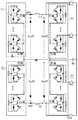
- Fig. 1is a schematic diagram of a power electronic module test device provided by an embodiment of the present application.
- the power electronic module test deviceincludes four converter valve valve sections, a first reactance L1, a second reactance L2, a power source Em, at least two charging switches Ky1, Ky2, and at least two supplementary energy switches Km1, Km2.
- the four converter valve segmentsinclude the first converter valve segment V1, the second converter valve segment V2, the third converter valve segment V3, and the fourth converter valve segment V4, each of which The segment includes at least one submodule M connected in series.
- the negative ends of the four converter valve sectionsare directly connected.
- the positive end of the first converter valve section V1 and the positive end of the second converter valve section V2are connected to both ends of the first reactance L1.
- the positive end of the valve section V3 of the flow valve, the positive end of the valve section V4 of the fourth converter valve and the two ends of the second reactance L2are respectively connected.
- the two ends of the first reactanceare respectively connected to the positive end of the first converter valve section V1 and the positive end of the second converter valve section V2.
- the two ends of the second reactanceare respectively connected to the positive end of the third converter valve section V3 and the positive end of the fourth converter valve section V4.
- the power source Emsupplies power to the four converter valve sections.
- One end of the two charging switches Ky1 and Ky2is connected to the power source, and the other end is respectively connected to one end of the first reactance L1 or the second reactance L2.
- One end of the two supplementary energy switches Km1 and Km2is connected to the power source Em, and the other end is respectively connected to one end of the capacitor of one of the submodules M of any two converter valve segments, so that the supplementary energy switch Km1 or Km2 is connected in series with the power source, and The capacitors are connected in parallel.
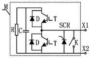
- the sub-module Mincludes two turn-off semiconductor switches T, two diodes D, a capacitor C and a resistor R, as shown in FIG. 2.
- the resistor R and the capacitor Care connected in parallel.
- Two semiconductor switches T that can be turned offare connected in series and then connected in parallel with the capacitor C.
- Each diode Dis connected in anti-parallel with a semiconductor switch T that can be turned off.
- the connection point of the two semiconductor switches T that can be turned offis the positive terminal of the submodule M, and the negative terminal of the capacitor C is the negative terminal of the submodule M.
- the sub-module Mis connected in parallel with at least one mechanical switch K or power electronic switch SCR.
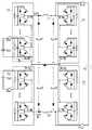
- the sub-module Mincludes four switchable semiconductor switches T, four diodes D, a capacitor C and a resistor R, as shown in FIG. 3.
- the resistor R and the capacitor Care connected in parallel.
- Four semiconductor switches T that can be turned offform a full-bridge circuit, and the DC terminal of the full-bridge circuit is connected in parallel with the capacitor C.
- Each of the four diodes Dis connected in anti-parallel with a semiconductor switch T that can be turned off.
- the AC terminals of the full bridge circuitare the positive terminal and the negative terminal of the submodule M, respectively.
- the sub-module Mis connected in parallel with at least one mechanical switch K or power electronic switch SCR.
- the technical solution provided by this embodimentcan effectively reproduce the stress under actual working conditions on the valve section of the converter valve, and can meet the test of the valve section of the converter valve with different voltage levels and power levels under actual working conditions.
- the number of sub-modules requiredis small, which reduces the risk of testing.
- the DC supplemental power supplyonly needs to output the voltage of one sub-module, and does not need to increase with the increase of the number of valve segments of the converter valve.
- the requirement for the power supply capacity of the power grid of the test siteis low, and only a minimum of 2 load reactances are required.
- Fig. 4is a schematic diagram of another power electronic module test device provided by an embodiment of the present application.
- the power electronic module test deviceincludes four converter valve valve sections, a first reactance L1, a second reactance L2, a charging power source Ey, a supplementary power source Em, at least two charging switches Ky1, Ky2, and at least two supplementary switches Km1, Km2.
- the four converter valve segmentsinclude the first converter valve segment V1, the second converter valve segment V2, the third converter valve segment V3, and the fourth converter valve segment V4, each of which The segment includes at least one submodule M connected in series.
- the negative ends of the four converter valve sectionsare directly connected.
- the positive end of the first converter valve section V1 and the positive end of the second converter valve section V2are connected to both ends of the first reactance L1.
- the positive end of the valve section V3 of the flow valve, the positive end of the valve section V4 of the fourth converter valve and the two ends of the second reactance L2are respectively connected.
- the two ends of the first reactance L1are respectively connected to the positive end of the first converter valve section V1 and the positive end of the second converter valve section V2.
- the two ends of the second reactance L2are respectively connected to the positive end of the third converter valve section V3 and the positive end of the fourth converter valve section V4.
- the charging power source Ey and the supplementary energy power source Emprovide power for the four converter valve segments.
- the charging power supply Eyis a DC power supply.
- the positive terminal of the charging power supply Eyis connected to one end of the two charging switches Ky1 and Ky2, and the negative terminal of the charging power supply Ey is connected to the negative terminals of the four converter valve segments.
- the supplementary energy source Emis a DC power supply.
- the positive end of the supplementary energy source Emis connected to one end of the two supplementary energy switches Km1 and Km2.
- the supplementary energy sourceis connected to the capacitor of one of the submodules M of any converter valve section through the supplementary energy switch. Connected in parallel.
- the other ends of the two charging switches Ky1 and Ky2are respectively connected to one end of the first reactance L1 and the second reactance L2.
- One end of the two supplementary energy switches Km1 and Km2is connected to the power source Em, and the other end is respectively connected to one end of the capacitor of one of the submodules M of any two converter valve segments, so that the supplementary energy switch Km1 or Km2 is connected in series with the power source, and The capacitors are connected in parallel.
- the charging power supply Eyprecharges the four converter valve segments. After the four converter valve segments are charged, disconnect the two charging switches Ky1 and Ky2, and close the two recharge switches Km1 and Km2 to control the converter valve segments.
- the sub-module Mincludes two turn-off semiconductor switches T, two diodes D, a capacitor C and a resistor R, as shown in FIG. 2.
- the resistor R and the capacitor Care connected in parallel.
- Two semiconductor switches T that can be turned offare connected in series and then connected in parallel with the capacitor C.
- Each diode Dis connected in anti-parallel with a semiconductor switch T that can be turned off.
- the connection point of the two semiconductor switches T that can be turned offis the positive terminal of the submodule M, and the negative terminal of the capacitor C is the negative terminal of the submodule M.
- the sub-module Mis connected in parallel with at least one mechanical switch K or power electronic switch SCR.
- the sub-module Mincludes four switchable semiconductor switches T, four diodes D, a capacitor C and a resistor R, as shown in FIG. 3.
- the resistor and the capacitorare connected in parallel.
- Four semiconductor switches T that can be turned offform a full-bridge circuit, and the DC terminal of the full-bridge circuit is connected in parallel with the capacitor C.
- Each of the four diodes Dis connected in anti-parallel with a semiconductor switch T that can be turned off.
- the AC terminals of the full bridge circuitare the positive terminal and the negative terminal of the submodule M, respectively.
- the sub-module Mis connected in parallel with at least one mechanical switch K or power electronic switch SCR.
- the technical solution provided by this embodimentcan effectively reproduce the stress under actual working conditions on the valve section of the converter valve, and can meet the test of the valve section of the converter valve with different voltage levels and power levels under actual working conditions.
- the number of sub-modules requiredis small, which reduces the risk of testing.
- the DC supplemental power supplyonly needs to output the voltage of one sub-module, and does not need to increase with the increase of the number of valve segments of the converter valve.
- the requirement for the power supply capacity of the power grid of the test siteis low, and only a minimum of 2 load reactances are required.
- Fig. 5is a schematic diagram of another power electronic module test device provided by an embodiment of the present application.
- the power electronic module test deviceincludes four converter valve valve sections, a first reactance L1, a second reactance L2, a charging power source Ey, a supplementary power source Em, at least two charging switches Ky1, Ky2, and at least two supplementary switches Km1, Km2.
- the four converter valve segmentsinclude the first converter valve segment V1, the second converter valve segment V2, the third converter valve segment V3, and the fourth converter valve segment V4, each of which The segment includes at least one submodule M connected in series.
- the negative ends of the four converter valve sectionsare directly connected.
- the positive end of the first converter valve section V1 and the positive end of the second converter valve section V2are connected to both ends of the first reactance L1.
- the positive end of the valve section V3 of the flow valve, the positive end of the valve section V4 of the fourth converter valve and the two ends of the second reactance L2are respectively connected.
- the two ends of the first reactance L1are respectively connected to the positive end of the first converter valve section V1 and the positive end of the second converter valve section V2.
- the two ends of the second reactance L2are respectively connected to the positive end of the third converter valve section V3 and the positive end of the fourth converter valve section V4.
- the charging power source Ey and the supplementary energy power source Emprovide power for the four converter valve segments.
- the charging power source Eyis an AC power source, and both ends of the charging power source Ey are respectively connected to one end of the two charging switches Ky1 and Ky2.
- the compensation power source Emis a DC power supply.
- the positive end of the compensation power supply Emis connected to one end of the two compensation switches Km1 and Km2.
- the compensation power supply Emis connected to the capacitor of one of the sub-modules of any converter valve section through the compensation switch. Connected in parallel.
- the other ends of the two charging switches Ky1 and Ky2are respectively connected to one end of the first reactance L1 and the second reactance L2.
- One end of the two recharge switches Km1 and Km2is connected to the power source Em, and the other end is respectively connected to one end of the capacitor of one of the submodules M of any two converter valve sections, so that the recharge switch Km1 or Km2 is connected in series with the recharge power Em After that, it is connected in parallel with the capacitor.
- the charging power supply Eyprecharges the four converter valve segments. After the four converter valve segments are charged, disconnect the two charging switches Ky1 and Ky2, and close the two recharge switches Km1 and Km2 to control the converter valve segments.
- the sub-module Mincludes two turn-off semiconductor switches T, two diodes D, a capacitor C and a resistor R, as shown in FIG. 2.
- the resistor R and the capacitor Care connected in parallel.
- Two semiconductor switches T that can be turned offare connected in series and then connected in parallel with the capacitor C.
- Each diode Dis connected in anti-parallel with a semiconductor switch T that can be turned off.
- the connection point of the two semiconductor switches T that can be turned offis the positive terminal of the submodule M, and the negative terminal of the capacitor C is the negative terminal of the submodule M.
- the sub-module Mis connected in parallel with at least one mechanical switch K or power electronic switch SCR.
- the sub-module Mincludes four switchable semiconductor switches T, four diodes D, a capacitor C and a resistor R, as shown in FIG. 3.
- the resistor and the capacitorare connected in parallel.
- Four semiconductor switches T that can be turned offform a full-bridge circuit, and the DC terminal of the full-bridge circuit is connected in parallel with the capacitor C.
- Each of the four diodes Dis connected in anti-parallel with a semiconductor switch T that can be turned off.
- the AC terminals of the full bridge circuitare the positive terminal and the negative terminal of the submodule M, respectively.
- the sub-module Mis connected in parallel with at least one mechanical switch or power electronic switch.
- the technical solution provided by this embodimentcan effectively reproduce the stress under actual working conditions on the valve section of the converter valve, and can meet the test of the valve section of the converter valve with different voltage levels and power levels under actual working conditions.
- the number of sub-modules requiredis small, which reduces the risk of testing.
- the DC supplemental power supplyonly needs to output the voltage of one sub-module, and does not need to increase with the increase of the number of valve segments of the converter valve.
- the requirement for the power supply capacity of the power grid of the test siteis low, and only a minimum of 2 load reactances are required.
- Fig. 6is a schematic diagram of still another power electronic module test device provided by an embodiment of the present application.
- the power electronic module test deviceincludes four converter valve valve sections, a first reactance L1, a second reactance L2, a charging power supply Ey, a supplementary power supply Em1, a supplementary power supply Em2, at least two charging switches Ky1, Ky2, and at least two Complementary energy switch Km1, Km2.
- the four converter valve segmentsinclude the first converter valve segment V1, the second converter valve segment V2, the third converter valve segment V3, and the fourth converter valve segment V4, each of which The segment includes at least one submodule M connected in series.
- the negative ends of the four converter valve sectionsare directly connected.
- the positive end of the first converter valve section V1 and the positive end of the second converter valve section V2are connected to both ends of the first reactance L1.
- the positive end of the valve section V3 of the flow valve, the positive end of the valve section V4 of the fourth converter valve and the two ends of the second reactance L2are respectively connected.
- the two ends of the first reactance L1are respectively connected to the positive end of the first converter valve section V1 and the positive end of the second converter valve section V2.
- the two ends of the second reactance L2are respectively connected to the positive end of the third converter valve section V3 and the positive end of the fourth converter valve section V4.
- the charging power supply Eysupplies power to the four converter valve segments.
- the charging power source Eyis an AC power source, and both ends of the charging power source Ey are respectively connected to one end of the two charging switches Ky1 and Ky2.
- the rechargeable power source Em1 and Em2are DC power supplies.
- the positive end of the rechargeable power source Emis connected to one end of the two rechargeable switches Km1 and Km2.
- the rechargeable power source Emis connected to one of the sub-modules of any converter valve section through the rechargeable switch.
- the capacitorsare connected in parallel.
- the other ends of the two charging switches Ky1 and Ky2are respectively connected to one end of the first reactance L1 and the second reactance L2.
- One end of the energy supplement switch Km1is connected to the power source Em1, and the other end is respectively connected to one end of the capacitor of the submodule, so that the energy supplement switch Km1 is connected in series with the energy supplement power source Em1 and then connected in parallel with the capacitor.
- One end of the energy supplement switch Km2is connected to the power source Em2, and the other end is respectively connected to one end of the capacitor of the sub-module, so that the energy supplement switch Km2 and the energy supplement power source Em2 are connected in series and then connected in parallel with the capacitor.
- the charging power supply Eyprecharges the four converter valve segments. After the four converter valve segments are charged, disconnect the two charging switches Ky1 and Ky2, and close the two recharge switches Km1 and Km2 to control the converter valve segments.
- the sub-module Mincludes two turn-off semiconductor switches T, two diodes D, a capacitor C and a resistor R, as shown in FIG. 2.
- the resistor R and the capacitor Care connected in parallel.
- Two semiconductor switches T that can be turned offare connected in series and then connected in parallel with the capacitor C.
- Each diode Dis connected in anti-parallel with a semiconductor switch T that can be turned off.
- the connection point of the two semiconductor switches T that can be turned offis the positive terminal of the submodule M, and the negative terminal of the capacitor C is the negative terminal of the submodule M.
- the sub-module Mis connected in parallel with at least one mechanical switch K or power electronic switch SCR.
- the sub-module Mincludes four switchable semiconductor switches T, four diodes D, a capacitor C and a resistor R, as shown in FIG. 3.
- the resistor and the capacitorare connected in parallel.
- Four semiconductor switches T that can be turned offform a full-bridge circuit, and the DC terminal of the full-bridge circuit is connected in parallel with the capacitor C.
- Each of the four diodes Dis connected in anti-parallel with a semiconductor switch T that can be turned off.
- the AC terminals of the full bridge circuitare the positive terminal and the negative terminal of the submodule M, respectively.
- the sub-module Mis connected in parallel with at least one mechanical switch or power electronic switch.
- the technical solution provided by this embodimentcan effectively reproduce the stress under actual working conditions on the valve section of the converter valve, and can meet the test of the valve section of the converter valve with different voltage levels and power levels under actual working conditions.
- the number of sub-modules requiredis small, which reduces the risk of testing.
- the DC supplemental power supplyonly needs to output the voltage of one sub-module, and does not need to increase with the increase of the number of valve segments of the converter valve.
- the requirement for the power supply capacity of the power grid of the test siteis low, and only a minimum of 2 load reactances are required.
- FIG. 7is a schematic flowchart of a control method of a power electronic module test device provided by an embodiment of the present application.
- the electrical parameters of the converter valve sectioninclude the voltage values U c of all sub-modules in the converter valve section under operating conditions, the number of sub-modules in the converter valve section n, and the number of sub-modules in the converter valve section.
- the voltage modulation ratio m 1 and the voltage frequency ⁇ , etc.are not limited to this.
- the modulation wave corresponding to the first converter valve segment and the third converter valve segmentare determined Corresponding modulation wave.
- the current of the first reactanceis i p (t)
- the current of the second reactanceis i n (t)
- the second commutationis determined based on the difference between the current of the first reactance and the current of the second reactance, and the set voltage modulation wave of the series-connected components of the first and third converter valve segments
- the valve section and the fourth converter valve sectionare connected in series to set the modulation ratio and phase of the voltage modulation wave.
- m 2is the modulation ratio of the voltage u b (t), Is the phase of the voltage u b (t).
- the modulation wave corresponding to the second converter valve section and the fourth converter valve sectionare determined.
- Controlling all sub-modules in the four converter valve segmentsincludes: modulating the trigger signals of all sub-modules in the four converter valve segments based on the modulation wave corresponding to each converter valve segment. Based on the trigger signal of the sub-module, all sub-modules in the four converter valve segments are controlled to be switched on or out, and the currents of the actual operating conditions of the four converter valve segments are obtained. All sub-modules in the four converter valve segments Establish the equivalent stress under actual working conditions.
- the technical solution provided by this embodimentcan effectively reproduce the stress under actual working conditions on the valve section of the converter valve, and can meet the test of the valve section of the converter valve with different voltage levels and power levels under actual working conditions.
- the DC supplemental power supplyonly needs to output the voltage of one sub-module, and does not need to increase with the increase of the number of valve segments of the converter valve.
- the requirement for the power supply capacity of the power grid of the test siteis low, and only a minimum of 2 load reactances are required.
- the voltage and current parameters of the controlled objectare transformed from the original AC and DC parameters into pure AC in real time, without the need to extract DC.
- the number of sub-modules requiredis much less than that of the existing back-to-back test method, which reduces the risk of the test.
Landscapes
- Engineering & Computer Science (AREA)
- Power Engineering (AREA)
- Computer Networks & Wireless Communication (AREA)
- Business, Economics & Management (AREA)
- Emergency Management (AREA)
- Small-Scale Networks (AREA)
- Remote Monitoring And Control Of Power-Distribution Networks (AREA)
- Rectifiers (AREA)
Abstract
Description
Translated fromChinese本申请涉及电力电子模块运行试验技术领域,具体涉及电力电子模块试验装置及其控制方法。This application relates to the technical field of power electronic module operation test, and specifically relates to a power electronic module test device and a control method thereof.
模块化多电平换流器(Modular Multilevel Converter,MMC)是柔性直流输电目前应用较为广泛的拓扑,具有模块化设计、有功和无功独立快速调节和易扩展等优点,在全球能源互联网可再生能源的并网及高压柔性直流输电领域得到广泛应用,是远距离传输、高容量、高效率、大规模清洁能源并网的较优选择。因此对模块化多电平电压源换流器中主要由可关断半导体器件组成的子模块能够建立等效呈现这些复杂应力的试验方法和装置,对于有效验证工程化应用实施可靠性是必要的。Modular Multilevel Converter (MMC) is the most widely used topology of flexible DC transmission at present. It has the advantages of modular design, independent rapid adjustment of active and reactive power, and easy expansion. It is renewable in the global energy network. The grid connection of energy and high-voltage flexible DC transmission are widely used, and they are the best choice for long-distance transmission, high capacity, high efficiency, and large-scale clean energy grid connection. Therefore, it is necessary to establish test methods and devices equivalent to these complex stresses for the sub-modules of the modular multi-level voltage source converter mainly composed of switchable semiconductor devices, which is necessary to effectively verify the reliability of engineering applications. .
对模块化多电平电压源换流器子模块等电力电子功率模块进行运行试验是为了验证在实际工况中长期稳态运行的子模块在其所受到的电压应力、电流应力和热应力等作用下是否能够稳定运行,目前现有技术的试验方案中,应用较多的一种方案,是在等效的背靠背小型化换流站试验平台上等效再现长期稳态运行的子模块所受到的电压应力、电流应力和热应力等,但这种方法不仅需要2个完整的换流站12个桥臂的换流阀,还受到试验场地电源容量的限制;另一种方法是利用4个换流阀阀段构成H桥试验系统,但是这种方法不仅需要5个电抗,还要提供高压直流补能电源,直流补能电源输出的直流电压甚至高达20kV以上,并且该直流电压随着换流阀试品桥臂子模块电平数继续增加而增加,特别是面对现今高压大容量柔性直流换流阀的子模块电压达到3kV以上的情况,对试验的实现有一定的限制;还有一种方法是利用2个换 流阀桥臂构成阀段试验系统,这种试验系统的需要控制的阀段端间电压和电流都带有直流偏置,控制时需要把控制对象的交直流电压和交直流电流的交流分量和直流分量先提取出来,才能进一步对系统进行控制,对系统的实时控制有一定的延迟,造成试验系统稳定性不强,也容易造成阀段中的三次电流谐波等零序电流的失控。The operation test of power electronic power modules such as modular multi-level voltage source converter sub-modules is to verify the voltage stress, current stress and thermal stress of the sub-modules that operate in a long-term steady state under actual working conditions. Whether it can operate stably under the effect, one of the most widely used test schemes in the current prior art is to reproduce the long-term steady-state operation of the sub-modules on the equivalent back-to-back miniaturized converter station test platform. Voltage stress, current stress and thermal stress, etc., but this method not only requires 2 complete converter stations with 12 bridge arms, but is also limited by the power capacity of the test site; another method is to use 4 The converter valve valve section constitutes the H-bridge test system, but this method not only requires 5 reactances, but also provides a high-voltage DC supplemental power supply. The DC voltage output by the DC supplementary power supply can even be as high as 20kV and above, and the DC voltage will change with the change. The number of sub-modules of the bridge arm of the flow valve test product continues to increase and increases, especially when the voltage of the sub-modules of the current high-voltage large-capacity flexible DC converter valve exceeds 3kV, there are certain restrictions on the realization of the test; another One method is to use two converter valve bridge arms to form a valve segment test system. In this test system, the voltage and current between the valve segments that need to be controlled have a DC bias. When controlling, the AC and DC voltage of the control object needs to be combined with the The AC component and DC component of the AC and DC currents are extracted first before the system can be further controlled. There is a certain delay to the real-time control of the system, which causes the stability of the test system to be weak, and it is easy to cause the third current harmonics in the valve section, etc. Out of control of the zero sequence current.
发明内容Summary of the invention
本申请实施例提供一种电力电子模块试验装置,所述试验装置包括四个换流阀阀段、第一电抗、第二电抗、电源、至少两个充电开关和至少两个补能开关,包括第一换流阀阀段、第二换流阀阀段、第三换流阀阀段和第四换流阀阀段,每个所述换流阀阀段包括串联连接的至少一个子模块,所述四个换流阀阀段的负端直接相连,所述第一换流阀阀段的正端、第二换流阀阀段的正端与第一电抗的两端分别相连,所述第三换流阀阀段的正端、第四换流阀阀段的正端与第二电抗的两端分别相连;所述第一电抗的两端分别连接所述第一换流阀阀段的正端和第二换流阀阀段的正端;所述第二电抗的两端分别连接所述第三换流阀阀段的正端和第四换流阀阀段的正端;所述电源为所述四个换流阀阀段供电;所述至少两个充电开关的一端连接所述电源,另一端分别连接所述第一电抗和第二电抗的一端;所述至少两个补能开关的一端连接所述电源,另一端分别连接任意两个换流阀阀段的其中一个子模块的电容的一端,使得所述补能开关与所述电源串联后,与所述电容并联。An embodiment of the application provides a test device for a power electronic module. The test device includes four converter valve valve sections, a first reactance, a second reactance, a power source, at least two charging switches, and at least two supplementary switches, including The first, second, third, and fourth converter valve segments, each of the converter valve segments includes at least one sub-module connected in series, The negative ends of the four converter valve valve sections are directly connected, and the positive end of the first converter valve valve section and the positive end of the second converter valve valve section are respectively connected to the two ends of the first reactance. The positive end of the valve section of the third converter valve and the positive end of the valve section of the fourth converter valve are respectively connected to the two ends of the second reactance; the two ends of the first reactance are respectively connected to the first converter valve section The positive end of the valve section of the second converter valve and the positive end of the valve section of the second converter valve; the two ends of the second reactance are respectively connected to the positive end of the valve section of the third converter valve and the positive end of the valve section of the fourth converter valve; The power supply supplies power to the four converter valve segments; one end of the at least two charging switches is connected to the power supply, and the other end is connected to one end of the first reactance and the second reactance; One end of the switchable switch is connected to the power source, and the other end is respectively connected to one end of a capacitor of one of the sub-modules of any two converter valve segments, so that the supplemental energy switch is connected in series with the power source and then connected in parallel with the capacitor.
根据一些实施例,所述电源包括充电电源和至少一个补能电源,所述充电电源为直流电源,所述充电电源的正端连接所述至少两个充电开关的一端,所述充电电源的负端连接所述四个换流阀阀段的负端;所述补能电源为直流电源,所述补能电源的正端连接所述至少两个补能开关的一端,所述补能电源通过补能开关与任一个换流阀阀段的其中一个子模块的电容并联连接。According to some embodiments, the power supply includes a charging power supply and at least one supplemental power supply, the charging power supply is a DC power supply, the positive end of the charging power supply is connected to one end of the at least two charging switches, and the negative end of the charging power supply is Terminal is connected to the negative end of the four converter valve valve sections; the supplemental power source is a DC power source, the positive terminal of the supplemental power source is connected to one end of the at least two supplementary switches, and the supplementary power source passes through The supplemental energy switch is connected in parallel with the capacitor of one of the sub-modules of any valve section of the converter valve.
根据一些实施例,所述电源包括充电电源和至少一个补能电源,所 述充电电源为交流电源,所述充电电源的两端分别连接所述至少两个充电开关的一端;所述补能电源为直流电源,所述补能电源的正端连接所述至少两个补能开关的一端,所述补能电源通过补能开关与任一个换流阀阀段的其中一个子模块的电容并联连接。According to some embodiments, the power supply includes a charging power supply and at least one rechargeable power supply, the recharging power supply is an AC power supply, and two ends of the charging power supply are respectively connected to one end of the at least two charging switches; the rechargeable power supply It is a direct current power supply, the positive end of the rechargeable power supply is connected to one end of the at least two rechargeable switches, and the rechargeable power supply is connected in parallel with the capacitor of one of the submodules of any converter valve section through the rechargeable switch .
根据一些实施例,所述子模块包括两个可关断半导体开关、两个二极管、电容和电阻,所述电阻与所述电容并联连接;所述两个可关断半导体开关串联连接后与所述电容并联连接;每个所述二极管与一个所述可关断半导体开关反向并联连接;其中,所述两个可关断半导体开关的连接点为所述子模块的正端,所述电容的负端为所述子模块的负端。According to some embodiments, the sub-module includes two turn-off semiconductor switches, two diodes, a capacitor, and a resistor, and the resistor is connected in parallel with the capacitor; the two turn-off semiconductor switches are connected in series with the capacitor. The capacitors are connected in parallel; each of the diodes is connected in anti-parallel to one of the turn-off semiconductor switches; wherein the connection point of the two turn-off semiconductor switches is the positive terminal of the sub-module, and the capacitor The negative terminal of is the negative terminal of the sub-module.
根据一些实施例,所述子模块包括四个可关断半导体开关、四个二极管、电容和电阻,所述电阻与所述电容并联连接;四个可关断半导体开关,构成一个全桥电路,所述全桥电路直流端与所述电容并联连接;每个所述二极管与一个所述可关断半导体开关反向并联连接;其中,所述全桥电路的交流端分别为所述子模块的正端和负端。According to some embodiments, the sub-module includes four turn-off semiconductor switches, four diodes, capacitors and resistors, the resistors are connected in parallel with the capacitor; four turn-off semiconductor switches form a full bridge circuit, The DC terminal of the full-bridge circuit is connected in parallel with the capacitor; each of the diodes is connected in anti-parallel with one of the turn-off semiconductor switches; wherein the AC terminals of the full-bridge circuit are respectively the sub-modules Positive and negative ends.
根据一些实施例,所述子模块至少并联一个机械开关或者电力电子开关。According to some embodiments, the sub-module is connected in parallel with at least one mechanical switch or power electronic switch.
本申请实施例还提供一种电力电子模块试验装置的控制方法,包括:基于换流阀阀段的电参数,确定第一换流阀阀段和第三换流阀阀段串联组成部分的设定电压调制波;基于所述第一换流阀阀段和第三换流阀阀段串联组成部分的设定电压调制波,确定所述第一换流阀阀段对应的调制波和所述第三换流阀阀段对应的调制波;实时检测第一电抗的电流和第二电抗的电流;基于所述第一电抗的电流和第二电抗的电流的差、所述第一换流阀阀段和第三换流阀阀段串联组成部分的设定电压调制波,来确定第二换流阀阀段和第四换流阀阀段串联组成部分的设定电压调制波的调制比和相位;基于所述第二换流阀阀段和第四换流阀阀段串联组成部分的设定电压调制波及其调制比和相位,确定所述第二换流阀阀段对应的调制波和所述第四换流阀阀段对应的调制波;基于每个换流阀阀段对应的调制波,进行四个换流阀阀段中所有子模块的控制。An embodiment of the present application also provides a control method of a power electronic module test device, which includes: determining the serial components of the first converter valve segment and the third converter valve segment based on the electrical parameters of the converter valve segment. Constant voltage modulation wave; based on the set voltage modulation wave of the serial component of the first converter valve section and the third converter valve section, determine the modulation wave corresponding to the first converter valve section and the The modulation wave corresponding to the valve section of the third converter valve; real-time detection of the current of the first reactance and the current of the second reactance; based on the difference between the current of the first reactance and the current of the second reactance, the first converter valve The set voltage modulation wave of the series connection component of the valve section and the third converter valve section is used to determine the modulation ratio and the modulation ratio of the set voltage modulation wave of the series connection component of the second and fourth converter valve section Phase; based on the set voltage modulation wave and its modulation ratio and phase of the series-connected components of the second converter valve valve section and the fourth converter valve section, determine the modulation wave sum corresponding to the second converter valve valve section The modulation wave corresponding to the fourth converter valve valve section; based on the modulation wave corresponding to each converter valve valve section, the control of all sub-modules in the four converter valve valve sections is performed.
根据一些实施例,所述基于每个换流阀阀段对应的调制波,进行四个换流阀阀段中所有子模块的控制包括:基于每个换流阀阀段对应的调制波,调制出四个换流阀阀段中所有子模块的触发信号;基于所述子模块的触发信号,控制四个换流阀阀段中所有所述子模块投入或退出,得到所述四个换流阀阀段实际运行工况的电流,所述四个换流阀阀段中的所有所述子模块建立起等效实际工况下的应力。According to some embodiments, the control of all sub-modules in the four converter valve segments based on the modulation wave corresponding to each converter valve segment includes: modulating based on the modulation wave corresponding to each converter valve segment Output the trigger signals of all the sub-modules in the four converter valve segments; based on the trigger signals of the sub-modules, control the input or withdrawal of all the sub-modules in the four converter valve segments to obtain the four converters The current of the valve section under the actual operating condition, and all the sub-modules in the four converter valve sections establish the equivalent stress under the actual operating condition.
根据一些实施例,所述换流阀阀段的电参数包括所述换流阀阀段中的所有子模块运行工况下的电压值Uc、所述换流阀阀段中的子模块个数n、所述换流阀阀段中电压调制比m1和电压频率ω、所述第一换流阀阀段和所述第三换流阀阀段串联组成部分的电压调制波ua(t)=nm1Ucsin(ωt)。According to some embodiments, the electrical parameters of the valve section of the converter valve include voltage values Uc under operating conditions of all sub-modules in the valve section of the converter valve, and the number of sub-modules in the valve section of the converter valve. The number n, the voltage modulation ratio m1 and the voltage frequency ω in the valve section of the converter valve, the voltage modulation wave ua ( t)=nm1 Uc sin(ωt).
根据一些实施例,所述第一换流阀阀段和第三换流阀阀段串联组成部分的设定电压调制波为ua(t)=upa(t)-una(t),所述第一换流阀阀段对应的调制波为upa(t)=nUc/2+ua(t)/2,所述第三换流阀阀段对应的调制波为una(t)=nUc/2-ua(t)/2。According to some embodiments, the set voltage modulation wave of the series-connected component of the first converter valve section and the third converter valve section is ua (t) = upa (t)-una (t), The modulation wave corresponding to the first converter valve segment is upa (t)=nUc /2+ ua (t)/2, and the modulation wave corresponding to the third converter valve segment is una ( t)=nUc /2- ua (t)/2.
根据一些实施例,所述第二换流阀阀段和第四换流阀阀段串联组成部分的设定电压调制波为

根据一些实施例,所述第一电抗的电流为ip(t),所述第二电抗的电流为in(t),所述第一电抗的电流和所述第二电抗的电流的差为i(t)=ip(t)-in(t)。According to some embodiments, the current of the first reactance is ip (t), the current of the second reactance is in (t), and the difference between the current of the first reactance and the current of the second reactance It is i(t)=ip (t)-in (t).
本申请实施例提供的技术方案,可在换流阀阀段上等效再现实际工况下的应力,可满足不同电压等级和功率等级的换流阀阀段在实际工况下的试验。同时需要的子模块数量少,降低了试验的风险性。The technical solutions provided by the embodiments of the present application can effectively reproduce the stresses under actual operating conditions on the valve sections of the converter valves, and can meet the test of the valve sections of the converter valves of different voltage levels and power levels under actual operating conditions. At the same time, the number of sub-modules required is small, which reduces the risk of testing.
为了更清楚地说明本申请实施例中的技术方案,下面将对实施例描 述中所需要使用的附图作简单地介绍,显而易见地,下面描述中的附图仅仅是本申请的一些实施例,对于本领域普通技术人员来讲,在不付出创造性劳动的前提下,还可以根据这些附图获得其他的附图。In order to more clearly describe the technical solutions in the embodiments of the present application, the following will briefly introduce the drawings that need to be used in the description of the embodiments. Obviously, the drawings in the following description are only some embodiments of the present application. For those of ordinary skill in the art, other drawings can be obtained based on these drawings without creative work.
图1是本申请实施例提供的一种电力电子模块试验装置示意图。Fig. 1 is a schematic diagram of a power electronic module test device provided by an embodiment of the present application.
图2是本申请实施例提供的一种子模块示意图。Fig. 2 is a schematic diagram of a sub-module provided by an embodiment of the present application.
图3是本申请实施例提供的另一种子模块示意图。Fig. 3 is a schematic diagram of another seed module provided by an embodiment of the present application.
图4是本申请实施例提供的另一种电力电子模块试验装置示意图。Fig. 4 is a schematic diagram of another power electronic module test device provided by an embodiment of the present application.
图5是本申请实施例提供的又一种电力电子模块试验装置示意图。Fig. 5 is a schematic diagram of another power electronic module test device provided by an embodiment of the present application.
图6是本申请实施例提供的再一种电力电子模块试验装置示意图。Fig. 6 is a schematic diagram of still another power electronic module test device provided by an embodiment of the present application.
图7是本申请实施例提供的一种电力电子模块试验装置的控制方法流程示意图。FIG. 7 is a schematic flowchart of a control method of a power electronic module test device provided by an embodiment of the present application.
下面将结合本申请实施例中的附图,对本申请实施例中的技术方案进行清楚、完整地描述,显然,所描述的实施例是本申请一部分实施例,而不是全部的实施例。基于本申请中的实施例,本领域技术人员在没有做出创造性劳动前提下所获得的所有其他实施例,都属于本申请保护的范围。The technical solutions in the embodiments of the present application will be described clearly and completely in conjunction with the accompanying drawings in the embodiments of the present application. Obviously, the described embodiments are part of the embodiments of the present application, rather than all of them. Based on the embodiments in this application, all other embodiments obtained by those skilled in the art without creative work shall fall within the protection scope of this application.
应当理解,本申请的权利要求、说明书及附图中的术语“第一”、“第二”、“第三”、“第四”等是用于区别不同对象,而不是用于描述特定顺序。本申请的说明书和权利要求书中使用的术语“包括”和“包含”指示所描述特征、整体、步骤、操作、元素和/或组件的存在,但并不排除一个或多个其它特征、整体、步骤、操作、元素、组件和/或其集合的存在或添加。It should be understood that the terms "first", "second", "third", "fourth", etc. in the claims, specification and drawings of this application are used to distinguish different objects, rather than to describe a specific sequence. . The terms "comprising" and "comprising" used in the specification and claims of this application indicate the existence of the described features, wholes, steps, operations, elements and/or components, but do not exclude one or more other features, wholes The existence or addition of, steps, operations, elements, components, and/or their collections.
图1是本申请实施例提供的一种电力电子模块试验装置示意图。Fig. 1 is a schematic diagram of a power electronic module test device provided by an embodiment of the present application.
电力电子模块试验装置包括四个换流阀阀段、第一电抗L1、第二电抗L2、电源Em、至少两个充电开关Ky1、Ky2和至少两个补能开关Km1、Km2。The power electronic module test device includes four converter valve valve sections, a first reactance L1, a second reactance L2, a power source Em, at least two charging switches Ky1, Ky2, and at least two supplementary energy switches Km1, Km2.
四个换流阀阀段包括第一换流阀阀段V1、第二换流阀阀段V2、第三换流阀阀段V3和第四换流阀阀段V4,每个换流阀阀段包括串联连接的至少一个子模块M。四个换流阀阀段的负端直接相连,第一换流阀阀段V1的正端、第二换流阀阀段V2的正端与第一电抗L1的两端分别相连,第三换流阀阀段V3的正端、第四换流阀阀段V4的正端与第二电抗L2的两端分别相连。第一电抗的两端分别连接第一换流阀阀段V1的正端和第二换流阀阀段V2的正端。第二电抗的两端分别连接第三换流阀阀段V3的正端和第四换流阀阀段V4的正端。电源Em为四个换流阀阀段供电。两个充电开关Ky1、Ky2的一端连接电源,另一端分别连接第一电抗L1或第二电抗L2的一端。两个补能开关Km1、Km2的一端连接电源Em,另一端分别连接任意两个换流阀阀段的其中一个子模块M的电容的一端,使得补能开关Km1或Km2与电源串联后,与电容并联。The four converter valve segments include the first converter valve segment V1, the second converter valve segment V2, the third converter valve segment V3, and the fourth converter valve segment V4, each of which The segment includes at least one submodule M connected in series. The negative ends of the four converter valve sections are directly connected. The positive end of the first converter valve section V1 and the positive end of the second converter valve section V2 are connected to both ends of the first reactance L1. The positive end of the valve section V3 of the flow valve, the positive end of the valve section V4 of the fourth converter valve and the two ends of the second reactance L2 are respectively connected. The two ends of the first reactance are respectively connected to the positive end of the first converter valve section V1 and the positive end of the second converter valve section V2. The two ends of the second reactance are respectively connected to the positive end of the third converter valve section V3 and the positive end of the fourth converter valve section V4. The power source Em supplies power to the four converter valve sections. One end of the two charging switches Ky1 and Ky2 is connected to the power source, and the other end is respectively connected to one end of the first reactance L1 or the second reactance L2. One end of the two supplementary energy switches Km1 and Km2 is connected to the power source Em, and the other end is respectively connected to one end of the capacitor of one of the submodules M of any two converter valve segments, so that the supplementary energy switch Km1 or Km2 is connected in series with the power source, and The capacitors are connected in parallel.
合上两个充电开关Ky1、Ky2,断开两个补能开关Km1、Km2,电源Em给四个换流阀阀段进行预充电。四个换流阀阀段充电完成后,断开两个充电开关Ky1、Ky2,合上两个补能开关Km1、Km2,进行换流阀阀段的控制。Close the two charging switches Ky1 and Ky2, disconnect the two recharge switches Km1 and Km2, and the power supply Em will pre-charge the four converter valve segments. After the four converter valve segments are charged, disconnect the two charging switches Ky1 and Ky2, and close the two recharge switches Km1 and Km2 to control the converter valve segments.
子模块M包括两个可关断半导体开关T、两个二极管D、电容C和电阻R,如图2所示。The sub-module M includes two turn-off semiconductor switches T, two diodes D, a capacitor C and a resistor R, as shown in FIG. 2.
电阻R与电容C并联连接。两个可关断半导体开关T串联连接后与电容C并联连接。每个二极管D与一个可关断半导体开关T反向并联连接。两个可关断半导体开关T的连接点为子模块M的正端,电容C的负端为子模块M的负端。子模块M至少并联一个机械开关K或者电力电子开关SCR。The resistor R and the capacitor C are connected in parallel. Two semiconductor switches T that can be turned off are connected in series and then connected in parallel with the capacitor C. Each diode D is connected in anti-parallel with a semiconductor switch T that can be turned off. The connection point of the two semiconductor switches T that can be turned off is the positive terminal of the submodule M, and the negative terminal of the capacitor C is the negative terminal of the submodule M. The sub-module M is connected in parallel with at least one mechanical switch K or power electronic switch SCR.
子模块M包括四个可关断半导体开关T、四个二极管D、电容C和电阻R,如图3所示。The sub-module M includes four switchable semiconductor switches T, four diodes D, a capacitor C and a resistor R, as shown in FIG. 3.
电阻R与电容C并联连接。四个可关断半导体开关T构成一个全桥电路,全桥电路直流端与电容C并联连接。四个二极管中每个二极管D与一个可关断半导体开关T反向并联连接。全桥电路的交流端分别为子模块M的正端和负端。子模块M至少并联一个机械开关K或者电力电子开关SCR。The resistor R and the capacitor C are connected in parallel. Four semiconductor switches T that can be turned off form a full-bridge circuit, and the DC terminal of the full-bridge circuit is connected in parallel with the capacitor C. Each of the four diodes D is connected in anti-parallel with a semiconductor switch T that can be turned off. The AC terminals of the full bridge circuit are the positive terminal and the negative terminal of the submodule M, respectively. The sub-module M is connected in parallel with at least one mechanical switch K or power electronic switch SCR.
本实施例提供的技术方案,可在换流阀阀段上等效再现实际工况下的应力,可满足不同电压等级和功率等级的换流阀阀段在实际工况下的试验。同时需要的子模块数量少,降低了试验的风险性。直流补能电源只要输出一个子模块的电压即可,无需随着换流阀阀段电平数的增加而增加,对试验场地电网电源容量的要求较低,并且只需要最少2个负载电抗。The technical solution provided by this embodiment can effectively reproduce the stress under actual working conditions on the valve section of the converter valve, and can meet the test of the valve section of the converter valve with different voltage levels and power levels under actual working conditions. At the same time, the number of sub-modules required is small, which reduces the risk of testing. The DC supplemental power supply only needs to output the voltage of one sub-module, and does not need to increase with the increase of the number of valve segments of the converter valve. The requirement for the power supply capacity of the power grid of the test site is low, and only a minimum of 2 load reactances are required.
图4是本申请实施例提供的另一种电力电子模块试验装置示意图。Fig. 4 is a schematic diagram of another power electronic module test device provided by an embodiment of the present application.
电力电子模块试验装置包括四个换流阀阀段、第一电抗L1、第二电抗L2、充电电源Ey、补能电源Em、至少两个充电开关Ky1、Ky2和至少两个补能开关Km1、Km2。The power electronic module test device includes four converter valve valve sections, a first reactance L1, a second reactance L2, a charging power source Ey, a supplementary power source Em, at least two charging switches Ky1, Ky2, and at least two supplementary switches Km1, Km2.
四个换流阀阀段包括第一换流阀阀段V1、第二换流阀阀段V2、第三换流阀阀段V3和第四换流阀阀段V4,每个换流阀阀段包括串联连接的至少一个子模块M。四个换流阀阀段的负端直接相连,第一换流阀阀段V1的正端、第二换流阀阀段V2的正端与第一电抗L1的两端分别相连,第三换流阀阀段V3的正端、第四换流阀阀段V4的正端与第二电抗L2的两端分别相连。第一电抗L1的两端分别连接第一换流阀阀段V1的正端和第二换流阀阀段V2的正端。第二电抗L2的两端分别连接第三换流阀阀段V3的正端和第四换流阀阀段V4的正端。The four converter valve segments include the first converter valve segment V1, the second converter valve segment V2, the third converter valve segment V3, and the fourth converter valve segment V4, each of which The segment includes at least one submodule M connected in series. The negative ends of the four converter valve sections are directly connected. The positive end of the first converter valve section V1 and the positive end of the second converter valve section V2 are connected to both ends of the first reactance L1. The positive end of the valve section V3 of the flow valve, the positive end of the valve section V4 of the fourth converter valve and the two ends of the second reactance L2 are respectively connected. The two ends of the first reactance L1 are respectively connected to the positive end of the first converter valve section V1 and the positive end of the second converter valve section V2. The two ends of the second reactance L2 are respectively connected to the positive end of the third converter valve section V3 and the positive end of the fourth converter valve section V4.
充电电源Ey和补能电源Em为四个换流阀阀段供电。充电电源Ey 为直流电源,充电电源Ey的正端连接两个充电开关Ky1、Ky2的一端,充电电源Ey的负端连接四个换流阀阀段的负端。补能电源Em为直流电源,补能电源Em的正端连接两个补能开关Km1、Km2的一端,补能电源通过补能开关与任一个换流阀阀段的其中一个子模块M的电容并联连接。The charging power source Ey and the supplementary energy power source Em provide power for the four converter valve segments. The charging power supply Ey is a DC power supply. The positive terminal of the charging power supply Ey is connected to one end of the two charging switches Ky1 and Ky2, and the negative terminal of the charging power supply Ey is connected to the negative terminals of the four converter valve segments. The supplementary energy source Em is a DC power supply. The positive end of the supplementary energy source Em is connected to one end of the two supplementary energy switches Km1 and Km2. The supplementary energy source is connected to the capacitor of one of the submodules M of any converter valve section through the supplementary energy switch. Connected in parallel.
两个充电开关Ky1、Ky2的另一端分别连接第一电抗L1和第二电抗L2的一端。两个补能开关Km1、Km2的一端连接电源Em,另一端分别连接任意两个换流阀阀段的其中一个子模块M的电容的一端,使得补能开关Km1或Km2与电源串联后,与电容并联。The other ends of the two charging switches Ky1 and Ky2 are respectively connected to one end of the first reactance L1 and the second reactance L2. One end of the two supplementary energy switches Km1 and Km2 is connected to the power source Em, and the other end is respectively connected to one end of the capacitor of one of the submodules M of any two converter valve segments, so that the supplementary energy switch Km1 or Km2 is connected in series with the power source, and The capacitors are connected in parallel.
合上两个充电开关Ky1、Ky2,断开两个补能开关Km1、Km2,充电电源Ey给四个换流阀阀段进行预充电。四个换流阀阀段充电完成后,断开两个充电开关Ky1、Ky2,合上两个补能开关Km1、Km2,进行换流阀阀段的控制。Close the two charging switches Ky1 and Ky2, and disconnect the two recharge switches Km1 and Km2. The charging power supply Ey precharges the four converter valve segments. After the four converter valve segments are charged, disconnect the two charging switches Ky1 and Ky2, and close the two recharge switches Km1 and Km2 to control the converter valve segments.
子模块M包括两个可关断半导体开关T、两个二极管D、电容C和电阻R,如图2所示。The sub-module M includes two turn-off semiconductor switches T, two diodes D, a capacitor C and a resistor R, as shown in FIG. 2.
电阻R与电容C并联连接。两个可关断半导体开关T串联连接后与电容C并联连接。每个二极管D与一个可关断半导体开关T反向并联连接。两个可关断半导体开关T的连接点为子模块M的正端,电容C的负端为子模块M的负端。子模块M至少并联一个机械开关K或者电力电子开关SCR。The resistor R and the capacitor C are connected in parallel. Two semiconductor switches T that can be turned off are connected in series and then connected in parallel with the capacitor C. Each diode D is connected in anti-parallel with a semiconductor switch T that can be turned off. The connection point of the two semiconductor switches T that can be turned off is the positive terminal of the submodule M, and the negative terminal of the capacitor C is the negative terminal of the submodule M. The sub-module M is connected in parallel with at least one mechanical switch K or power electronic switch SCR.
子模块M包括四个可关断半导体开关T、四个二极管D、电容C和电阻R,如图3所示。The sub-module M includes four switchable semiconductor switches T, four diodes D, a capacitor C and a resistor R, as shown in FIG. 3.
电阻与电容并联连接。四个可关断半导体开关T构成一个全桥电路,全桥电路直流端与电容C并联连接。四个二极管中每个二极管D与一个可关断半导体开关T反向并联连接。全桥电路的交流端分别为子模块M的正端和负端。子模块M至少并联一个机械开关K或者电力电子开关SCR。The resistor and the capacitor are connected in parallel. Four semiconductor switches T that can be turned off form a full-bridge circuit, and the DC terminal of the full-bridge circuit is connected in parallel with the capacitor C. Each of the four diodes D is connected in anti-parallel with a semiconductor switch T that can be turned off. The AC terminals of the full bridge circuit are the positive terminal and the negative terminal of the submodule M, respectively. The sub-module M is connected in parallel with at least one mechanical switch K or power electronic switch SCR.
本实施例提供的技术方案,可在换流阀阀段上等效再现实际工况下的应力,可满足不同电压等级和功率等级的换流阀阀段在实际工况下的试验。同时需要的子模块数量少,降低了试验的风险性。直流补能电源只要输出一个子模块的电压即可,无需随着换流阀阀段电平数的增加而增加,对试验场地电网电源容量的要求较低,并且只需要最少2个负载电抗。The technical solution provided by this embodiment can effectively reproduce the stress under actual working conditions on the valve section of the converter valve, and can meet the test of the valve section of the converter valve with different voltage levels and power levels under actual working conditions. At the same time, the number of sub-modules required is small, which reduces the risk of testing. The DC supplemental power supply only needs to output the voltage of one sub-module, and does not need to increase with the increase of the number of valve segments of the converter valve. The requirement for the power supply capacity of the power grid of the test site is low, and only a minimum of 2 load reactances are required.
图5是本申请实施例提供的又一种电力电子模块试验装置示意图。Fig. 5 is a schematic diagram of another power electronic module test device provided by an embodiment of the present application.
电力电子模块试验装置包括四个换流阀阀段、第一电抗L1、第二电抗L2、充电电源Ey、补能电源Em、至少两个充电开关Ky1、Ky2和至少两个补能开关Km1、Km2。The power electronic module test device includes four converter valve valve sections, a first reactance L1, a second reactance L2, a charging power source Ey, a supplementary power source Em, at least two charging switches Ky1, Ky2, and at least two supplementary switches Km1, Km2.
四个换流阀阀段包括第一换流阀阀段V1、第二换流阀阀段V2、第三换流阀阀段V3和第四换流阀阀段V4,每个换流阀阀段包括串联连接的至少一个子模块M。四个换流阀阀段的负端直接相连,第一换流阀阀段V1的正端、第二换流阀阀段V2的正端与第一电抗L1的两端分别相连,第三换流阀阀段V3的正端、第四换流阀阀段V4的正端与第二电抗L2的两端分别相连。第一电抗L1的两端分别连接第一换流阀阀段V1的正端和第二换流阀阀段V2的正端。第二电抗L2的两端分别连接第三换流阀阀段V3的正端和第四换流阀阀段V4的正端。The four converter valve segments include the first converter valve segment V1, the second converter valve segment V2, the third converter valve segment V3, and the fourth converter valve segment V4, each of which The segment includes at least one submodule M connected in series. The negative ends of the four converter valve sections are directly connected. The positive end of the first converter valve section V1 and the positive end of the second converter valve section V2 are connected to both ends of the first reactance L1. The positive end of the valve section V3 of the flow valve, the positive end of the valve section V4 of the fourth converter valve and the two ends of the second reactance L2 are respectively connected. The two ends of the first reactance L1 are respectively connected to the positive end of the first converter valve section V1 and the positive end of the second converter valve section V2. The two ends of the second reactance L2 are respectively connected to the positive end of the third converter valve section V3 and the positive end of the fourth converter valve section V4.
充电电源Ey和补能电源Em为四个换流阀阀段供电。充电电源Ey为交流电源,充电电源Ey的两端分别连接两个充电开关Ky1、Ky2的一端。补能电源Em为直流电源,补能电源Em的正端连接两个补能开关Km1、Km2的一端,补能电源Em通过补能开关与任一个换流阀阀段的其中一个子模块的电容并联连接。The charging power source Ey and the supplementary energy power source Em provide power for the four converter valve segments. The charging power source Ey is an AC power source, and both ends of the charging power source Ey are respectively connected to one end of the two charging switches Ky1 and Ky2. The compensation power source Em is a DC power supply. The positive end of the compensation power supply Em is connected to one end of the two compensation switches Km1 and Km2. The compensation power supply Em is connected to the capacitor of one of the sub-modules of any converter valve section through the compensation switch. Connected in parallel.
两个充电开关Ky1、Ky2的另一端分别连接第一电抗L1和第二电抗L2的一端。两个补能开关Km1、Km2的一端连接电源Em,另一端分别连接任意两个换流阀阀段的其中一个子模块M的电容的一端,使 得补能开关Km1或Km2与补能电源Em串联后,与电容并联。The other ends of the two charging switches Ky1 and Ky2 are respectively connected to one end of the first reactance L1 and the second reactance L2. One end of the two recharge switches Km1 and Km2 is connected to the power source Em, and the other end is respectively connected to one end of the capacitor of one of the submodules M of any two converter valve sections, so that the recharge switch Km1 or Km2 is connected in series with the recharge power Em After that, it is connected in parallel with the capacitor.
合上两个充电开关Ky1、Ky2,断开两个补能开关Km1、Km2,充电电源Ey给四个换流阀阀段进行预充电。四个换流阀阀段充电完成后,断开两个充电开关Ky1、Ky2,合上两个补能开关Km1、Km2,进行换流阀阀段的控制。Close the two charging switches Ky1 and Ky2, and disconnect the two recharge switches Km1 and Km2. The charging power supply Ey precharges the four converter valve segments. After the four converter valve segments are charged, disconnect the two charging switches Ky1 and Ky2, and close the two recharge switches Km1 and Km2 to control the converter valve segments.
子模块M包括两个可关断半导体开关T、两个二极管D、电容C和电阻R,如图2所示。The sub-module M includes two turn-off semiconductor switches T, two diodes D, a capacitor C and a resistor R, as shown in FIG. 2.
电阻R与电容C并联连接。两个可关断半导体开关T串联连接后与电容C并联连接。每个二极管D与一个可关断半导体开关T反向并联连接。两个可关断半导体开关T的连接点为子模块M的正端,电容C的负端为子模块M的负端。子模块M至少并联一个机械开关K或者电力电子开关SCR。The resistor R and the capacitor C are connected in parallel. Two semiconductor switches T that can be turned off are connected in series and then connected in parallel with the capacitor C. Each diode D is connected in anti-parallel with a semiconductor switch T that can be turned off. The connection point of the two semiconductor switches T that can be turned off is the positive terminal of the submodule M, and the negative terminal of the capacitor C is the negative terminal of the submodule M. The sub-module M is connected in parallel with at least one mechanical switch K or power electronic switch SCR.
子模块M包括四个可关断半导体开关T、四个二极管D、电容C和电阻R,如图3所示。The sub-module M includes four switchable semiconductor switches T, four diodes D, a capacitor C and a resistor R, as shown in FIG. 3.
电阻与电容并联连接。四个可关断半导体开关T构成一个全桥电路,全桥电路直流端与电容C并联连接。四个二极管中每个二极管D与一个可关断半导体开关T反向并联连接。全桥电路的交流端分别为子模块M的正端和负端。子模块M至少并联一个机械开关或者电力电子开关。The resistor and the capacitor are connected in parallel. Four semiconductor switches T that can be turned off form a full-bridge circuit, and the DC terminal of the full-bridge circuit is connected in parallel with the capacitor C. Each of the four diodes D is connected in anti-parallel with a semiconductor switch T that can be turned off. The AC terminals of the full bridge circuit are the positive terminal and the negative terminal of the submodule M, respectively. The sub-module M is connected in parallel with at least one mechanical switch or power electronic switch.
本实施例提供的技术方案,可在换流阀阀段上等效再现实际工况下的应力,可满足不同电压等级和功率等级的换流阀阀段在实际工况下的试验。同时需要的子模块数量少,降低了试验的风险性。直流补能电源只要输出一个子模块的电压即可,无需随着换流阀阀段电平数的增加而增加,对试验场地电网电源容量的要求较低,并且只需要最少2个负载电抗。The technical solution provided by this embodiment can effectively reproduce the stress under actual working conditions on the valve section of the converter valve, and can meet the test of the valve section of the converter valve with different voltage levels and power levels under actual working conditions. At the same time, the number of sub-modules required is small, which reduces the risk of testing. The DC supplemental power supply only needs to output the voltage of one sub-module, and does not need to increase with the increase of the number of valve segments of the converter valve. The requirement for the power supply capacity of the power grid of the test site is low, and only a minimum of 2 load reactances are required.
图6是本申请实施例提供的再一种电力电子模块试验装置示意图。Fig. 6 is a schematic diagram of still another power electronic module test device provided by an embodiment of the present application.
电力电子模块试验装置包括四个换流阀阀段、第一电抗L1、第二电抗L2、充电电源Ey、补能电源Em1、补能电源Em2、至少两个充电开关Ky1、Ky2和至少两个补能开关Km1、Km2。The power electronic module test device includes four converter valve valve sections, a first reactance L1, a second reactance L2, a charging power supply Ey, a supplementary power supply Em1, a supplementary power supply Em2, at least two charging switches Ky1, Ky2, and at least two Complementary energy switch Km1, Km2.
四个换流阀阀段包括第一换流阀阀段V1、第二换流阀阀段V2、第三换流阀阀段V3和第四换流阀阀段V4,每个换流阀阀段包括串联连接的至少一个子模块M。四个换流阀阀段的负端直接相连,第一换流阀阀段V1的正端、第二换流阀阀段V2的正端与第一电抗L1的两端分别相连,第三换流阀阀段V3的正端、第四换流阀阀段V4的正端与第二电抗L2的两端分别相连。第一电抗L1的两端分别连接第一换流阀阀段V1的正端和第二换流阀阀段V2的正端。第二电抗L2的两端分别连接第三换流阀阀段V3的正端和第四换流阀阀段V4的正端。The four converter valve segments include the first converter valve segment V1, the second converter valve segment V2, the third converter valve segment V3, and the fourth converter valve segment V4, each of which The segment includes at least one submodule M connected in series. The negative ends of the four converter valve sections are directly connected. The positive end of the first converter valve section V1 and the positive end of the second converter valve section V2 are connected to both ends of the first reactance L1. The positive end of the valve section V3 of the flow valve, the positive end of the valve section V4 of the fourth converter valve and the two ends of the second reactance L2 are respectively connected. The two ends of the first reactance L1 are respectively connected to the positive end of the first converter valve section V1 and the positive end of the second converter valve section V2. The two ends of the second reactance L2 are respectively connected to the positive end of the third converter valve section V3 and the positive end of the fourth converter valve section V4.
充电电源Ey为四个换流阀阀段供电。充电电源Ey为交流电源,充电电源Ey的两端分别连接两个充电开关Ky1、Ky2的一端。补能电源Em1、Em2为直流电源,补能电源Em的正端连接两个补能开关Km1、Km2的一端,补能电源Em通过补能开关与任一个换流阀阀段的其中一个子模块的电容并联连接。The charging power supply Ey supplies power to the four converter valve segments. The charging power source Ey is an AC power source, and both ends of the charging power source Ey are respectively connected to one end of the two charging switches Ky1 and Ky2. The rechargeable power source Em1 and Em2 are DC power supplies. The positive end of the rechargeable power source Em is connected to one end of the two rechargeable switches Km1 and Km2. The rechargeable power source Em is connected to one of the sub-modules of any converter valve section through the rechargeable switch. The capacitors are connected in parallel.
两个充电开关Ky1、Ky2的另一端分别连接第一电抗L1和第二电抗L2的一端。补能开关Km1的一端连接电源Em1,另一端分别连接子模块的电容的一端,使得补能开关Km1与补能电源Em1串联后,与电容并联。补能开关Km2的一端连接电源Em2,另一端分别连接子模块的电容的一端,使得补能开关Km2与补能电源Em2串联后,与电容并联。The other ends of the two charging switches Ky1 and Ky2 are respectively connected to one end of the first reactance L1 and the second reactance L2. One end of the energy supplement switch Km1 is connected to the power source Em1, and the other end is respectively connected to one end of the capacitor of the submodule, so that the energy supplement switch Km1 is connected in series with the energy supplement power source Em1 and then connected in parallel with the capacitor. One end of the energy supplement switch Km2 is connected to the power source Em2, and the other end is respectively connected to one end of the capacitor of the sub-module, so that the energy supplement switch Km2 and the energy supplement power source Em2 are connected in series and then connected in parallel with the capacitor.
合上两个充电开关Ky1、Ky2,断开两个补能开关Km1、Km2,充电电源Ey给四个换流阀阀段进行预充电。四个换流阀阀段充电完成后,断开两个充电开关Ky1、Ky2,合上两个补能开关Km1、Km2,进行换流阀阀段的控制。Close the two charging switches Ky1 and Ky2, and disconnect the two recharge switches Km1 and Km2. The charging power supply Ey precharges the four converter valve segments. After the four converter valve segments are charged, disconnect the two charging switches Ky1 and Ky2, and close the two recharge switches Km1 and Km2 to control the converter valve segments.
子模块M包括两个可关断半导体开关T、两个二极管D、电容C和电阻R,如图2所示。The sub-module M includes two turn-off semiconductor switches T, two diodes D, a capacitor C and a resistor R, as shown in FIG. 2.
电阻R与电容C并联连接。两个可关断半导体开关T串联连接后与电容C并联连接。每个二极管D与一个可关断半导体开关T反向并联连接。两个可关断半导体开关T的连接点为子模块M的正端,电容C的负端为子模块M的负端。子模块M至少并联一个机械开关K或者电力电子开关SCR。The resistor R and the capacitor C are connected in parallel. Two semiconductor switches T that can be turned off are connected in series and then connected in parallel with the capacitor C. Each diode D is connected in anti-parallel with a semiconductor switch T that can be turned off. The connection point of the two semiconductor switches T that can be turned off is the positive terminal of the submodule M, and the negative terminal of the capacitor C is the negative terminal of the submodule M. The sub-module M is connected in parallel with at least one mechanical switch K or power electronic switch SCR.
子模块M包括四个可关断半导体开关T、四个二极管D、电容C和电阻R,如图3所示。The sub-module M includes four switchable semiconductor switches T, four diodes D, a capacitor C and a resistor R, as shown in FIG. 3.
电阻与电容并联连接。四个可关断半导体开关T构成一个全桥电路,全桥电路直流端与电容C并联连接。四个二极管中每个二极管D与一个可关断半导体开关T反向并联连接。全桥电路的交流端分别为子模块M的正端和负端。子模块M至少并联一个机械开关或者电力电子开关。The resistor and the capacitor are connected in parallel. Four semiconductor switches T that can be turned off form a full-bridge circuit, and the DC terminal of the full-bridge circuit is connected in parallel with the capacitor C. Each of the four diodes D is connected in anti-parallel with a semiconductor switch T that can be turned off. The AC terminals of the full bridge circuit are the positive terminal and the negative terminal of the submodule M, respectively. The sub-module M is connected in parallel with at least one mechanical switch or power electronic switch.
本实施例提供的技术方案,可在换流阀阀段上等效再现实际工况下的应力,可满足不同电压等级和功率等级的换流阀阀段在实际工况下的试验。同时需要的子模块数量少,降低了试验的风险性。直流补能电源只要输出一个子模块的电压即可,无需随着换流阀阀段电平数的增加而增加,对试验场地电网电源容量的要求较低,并且只需要最少2个负载电抗。The technical solution provided by this embodiment can effectively reproduce the stress under actual working conditions on the valve section of the converter valve, and can meet the test of the valve section of the converter valve with different voltage levels and power levels under actual working conditions. At the same time, the number of sub-modules required is small, which reduces the risk of testing. The DC supplemental power supply only needs to output the voltage of one sub-module, and does not need to increase with the increase of the number of valve segments of the converter valve. The requirement for the power supply capacity of the power grid of the test site is low, and only a minimum of 2 load reactances are required.
图7是本申请实施例提供的一种电力电子模块试验装置的控制方法流程示意图。FIG. 7 is a schematic flowchart of a control method of a power electronic module test device provided by an embodiment of the present application.
在S110中,基于换流阀阀段的电参数,确定第一换流阀阀段和第三换流阀阀段串联组成部分的设定电压调制波。In S110, based on the electrical parameters of the valve section of the converter valve, the set voltage modulation wave of the series-connected component of the first converter valve section and the third converter valve section is determined.
第一换流阀阀段和第三换流阀阀段串联组成部分的设定电压调制波为ua(t)=nm1Ucsin(ωt)。其中,换流阀阀段的电参数包括换流阀阀段中的所有子模块运行工况下的电压值Uc、换流阀阀段中的子模块个数n、换流阀阀段中电压调制比m1和电压频率ω等等,并不以此为限。The set voltage modulation wave of the serial components of the first converter valve section and the third converter valve section is ua (t) = nm1 Uc sin (ωt). Among them, the electrical parameters of the converter valve section include the voltage values Uc of all sub-modules in the converter valve section under operating conditions, the number of sub-modules in the converter valve section n, and the number of sub-modules in the converter valve section. The voltage modulation ratio m1 and the voltage frequency ω, etc. are not limited to this.
在S120中,基于第一换流阀阀段和第三换流阀阀段串联组成部分的设定电压调制波,确定第一换流阀阀段对应的调制波和第三换流阀阀段对应的调制波。In S120, based on the set voltage modulation wave of the serial components of the first and third converter valve segments, the modulation wave corresponding to the first converter valve segment and the third converter valve segment are determined Corresponding modulation wave.
由于,第一换流阀阀段和第三换流阀阀段串联组成部分的设定电压调制波同时还为ua(t)=upa(t)-una(t)。其中,upa(t)=nUc/2+ua(t)/2为第一换流阀阀段对应的调制波,una(t)=nUc/2-ua(t)/2为第三换流阀阀段对应的调制波。Because, the set voltage modulation wave of the series-connected component of the first converter valve section and the third converter valve section is also ua (t) = upa (t)-una (t) at the same time. Among them, upa (t) = nUc /2+ ua (t)/2 is the modulation wave corresponding to the valve section of the first converter valve, una (t) = nUc /2- ua (t)/ 2 is the modulation wave corresponding to the valve section of the third converter valve.
因此,依据上一步骤确定的第一换流阀阀段和第三换流阀阀段串联组成部分的设定电压调制波,可以确定第一换流阀阀段对应的调制波upa(t)和第三换流阀阀段对应的调制波una(t)。Therefore, according to the set voltage modulation wave of the series-connected component of the first converter valve section and the third converter valve section determined in the previous step, the modulation wave corresponding to the first converter valve section upa (t) And the modulation wave u na (t) corresponding to the third converter valve segment.
在S130中,实时检测第一电抗的电流和第二电抗的电流。In S130, the current of the first reactance and the current of the second reactance are detected in real time.
第一电抗的电流为ip(t),第二电抗的电流为in(t),第一电抗的电流和第二电抗的电流的差为i(t)=ip(t)-in(t)。The current of the first reactance is ip (t), the current of the second reactance is in (t), and the difference between the current of the first reactance and the current of the second reactance is i(t)=ip (t)-in (t).
在S140中,基于第一电抗的电流和第二电抗的电流的差、第一换流阀阀段和第三换流阀阀段串联组成部分的设定电压调制波,来确定第二换流阀阀段和第四换流阀阀段串联组成部分的设定电压调制波的调制比和相位。In S140, the second commutation is determined based on the difference between the current of the first reactance and the current of the second reactance, and the set voltage modulation wave of the series-connected components of the first and third converter valve segments The valve section and the fourth converter valve section are connected in series to set the modulation ratio and phase of the voltage modulation wave.
第二换流阀阀段和第四换流阀阀段串联组成部分的设定电压调制波为

在S150中,基于第二换流阀阀段和第四换流阀阀段串联组成部分的设定电压调制波及其调制比和相位,确定第二换流阀阀段对应的调制波和第四换流阀阀段对应的调制波。In S150, based on the set voltage modulation wave and its modulation ratio and phase of the series-connected components of the second converter valve section and the fourth converter valve section, the modulation wave corresponding to the second converter valve section and the fourth converter valve section are determined. The modulation wave corresponding to the valve section of the converter valve.
第二换流阀阀段对应的调制波为upb(t)=nUc/2+ub(t)/2,第四换流阀阀段对应的调制波为unb(t)=nUc/2-ub(t)/2。The modulation wave corresponding to the valve section of the second converter valve is upb (t) = nUc /2+ub (t)/2, and the modulation wave corresponding to the valve section of the fourth converter valve isunb (t) = nUc /2-ub (t)/2.
在S160中,基于每个换流阀阀段对应的调制波,进行四个换流阀阀段中所有子模块的控制。In S160, based on the modulation wave corresponding to each converter valve segment, control all sub-modules in the four converter valve segments.
进行四个换流阀阀段中所有子模块的控制包括:基于每个换流阀阀段对应的调制波,调制出四个换流阀阀段中所有子模块的触发信号。基于子模块的触发信号,控制四个换流阀阀段中所有子模块投入或退出,得到四个换流阀阀段实际运行工况的电流,四个换流阀阀段中的所有子模块建立起等效实际工况下的应力。Controlling all sub-modules in the four converter valve segments includes: modulating the trigger signals of all sub-modules in the four converter valve segments based on the modulation wave corresponding to each converter valve segment. Based on the trigger signal of the sub-module, all sub-modules in the four converter valve segments are controlled to be switched on or out, and the currents of the actual operating conditions of the four converter valve segments are obtained. All sub-modules in the four converter valve segments Establish the equivalent stress under actual working conditions.
本实施例提供的技术方案,可在换流阀阀段上等效再现实际工况下的应力,可满足不同电压等级和功率等级的换流阀阀段在实际工况下的试验。直流补能电源只要输出一个子模块的电压即可,无需随着换流阀阀段电平数的增加而增加,对试验场地电网电源容量的要求较低,并且只需要最少2个负载电抗。通过巧妙的控制方法设计,控制对象的电压和电流参量,由原来的交直流参量实时转化为纯交流,无需提取直流量。同时需要的子模块数量比现有背靠背试验方法需要少很多,降低了试验的风险性。The technical solution provided by this embodiment can effectively reproduce the stress under actual working conditions on the valve section of the converter valve, and can meet the test of the valve section of the converter valve with different voltage levels and power levels under actual working conditions. The DC supplemental power supply only needs to output the voltage of one sub-module, and does not need to increase with the increase of the number of valve segments of the converter valve. The requirement for the power supply capacity of the power grid of the test site is low, and only a minimum of 2 load reactances are required. Through the ingenious control method design, the voltage and current parameters of the controlled object are transformed from the original AC and DC parameters into pure AC in real time, without the need to extract DC. At the same time, the number of sub-modules required is much less than that of the existing back-to-back test method, which reduces the risk of the test.
以上对本申请实施例进行了详细介绍,本文中应用了具体个例对本申请的原理及实施方式进行了阐述,以上实施例的说明仅用于帮助理解本申请的方法及其核心思想。同时,本领域技术人员依据本申请的思想,基于本申请的具体实施方式及应用范围上做出的改变或变形之处,都属于本申请保护的范围。综上所述,本说明书内容不应理解为对本申请的限制。The embodiments of the present application are described in detail above, and specific examples are used in this article to illustrate the principles and implementation manners of the present application. The descriptions of the above embodiments are only used to help understand the methods and core ideas of the present application. At the same time, the changes or deformations made by those skilled in the art based on the ideas of the application, the specific implementation and the scope of application of the application, are all within the protection scope of the application. In summary, the content of this specification should not be construed as a limitation on this application.
Claims (12)
Translated fromChinese

Applications Claiming Priority (2)
| Application Number | Priority Date | Filing Date | Title |
|---|---|---|---|
| CN202010312614.9ACN111555443B (en) | 2020-04-20 | 2020-04-20 | Modularized series synchronous compensation system and control method thereof |
| CN202010312614.9 | 2020-04-20 |
Publications (1)
| Publication Number | Publication Date |
|---|---|
| WO2021213284A1true WO2021213284A1 (en) | 2021-10-28 |
Family
ID=72002962
Family Applications (1)
| Application Number | Title | Priority Date | Filing Date |
|---|---|---|---|
| PCT/CN2021/087889CeasedWO2021213284A1 (en) | 2020-04-20 | 2021-04-16 | Experiment device for power electronic module and control method therefor |
Country Status (2)
| Country | Link |
|---|---|
| CN (1) | CN111555443B (en) |
| WO (1) | WO2021213284A1 (en) |
Cited By (2)
| Publication number | Priority date | Publication date | Assignee | Title |
|---|---|---|---|---|
| CN115407147A (en)* | 2022-08-24 | 2022-11-29 | 南京南瑞继保电气有限公司 | Cascade module test circuit, method and system |
| CN115728579A (en)* | 2022-11-11 | 2023-03-03 | 国网辽宁省电力有限公司大连供电公司 | Multi-drag and multi-run test platform based on SVG full-bridge module |
Families Citing this family (3)
| Publication number | Priority date | Publication date | Assignee | Title |
|---|---|---|---|---|
| CN111555443B (en)* | 2020-04-20 | 2022-05-17 | 南京南瑞继保电气有限公司 | Modularized series synchronous compensation system and control method thereof |
| CN114079283A (en)* | 2020-08-19 | 2022-02-22 | 华为数字能源技术有限公司 | A power supply system and method |
| CN113178875B (en)* | 2021-05-13 | 2023-03-14 | 国家电网有限公司 | Series compensation system applied to 66kV power distribution network and control method thereof |
Citations (5)
| Publication number | Priority date | Publication date | Assignee | Title |
|---|---|---|---|---|
| CN202230181U (en)* | 2011-08-25 | 2012-05-23 | 中国电力科学研究院 | Power ring test apparatus for flexible DC power transmission MMC valve stable state operation test |
| CN202275142U (en)* | 2011-08-25 | 2012-06-13 | 中国电力科学研究院 | Back-to-back test device of a flexible direct-current transmission MMC valve steady-state operation test |
| JP2016010295A (en)* | 2014-06-26 | 2016-01-18 | 東芝三菱電機産業システム株式会社 | Test method and apparatus for transducer |
| CN107561456A (en)* | 2016-06-30 | 2018-01-09 | 南京南瑞继保电气有限公司 | A kind of power model experimental rig and test method |
| CN111555443A (en)* | 2020-04-20 | 2020-08-18 | 南京南瑞继保电气有限公司 | Modularized series synchronous compensation system and control method thereof |
Family Cites Families (2)
| Publication number | Priority date | Publication date | Assignee | Title |
|---|---|---|---|---|
| US6118676A (en)* | 1998-11-06 | 2000-09-12 | Soft Switching Technologies Corp. | Dynamic voltage sag correction |
| CN202004466U (en)* | 2010-12-28 | 2011-10-05 | 朱华锋 | Series transformer-free cascade multilevel dynamic voltage regulator |
- 2020
- 2020-04-20CNCN202010312614.9Apatent/CN111555443B/enactiveActive
- 2021
- 2021-04-16WOPCT/CN2021/087889patent/WO2021213284A1/ennot_activeCeased
Patent Citations (5)
| Publication number | Priority date | Publication date | Assignee | Title |
|---|---|---|---|---|
| CN202230181U (en)* | 2011-08-25 | 2012-05-23 | 中国电力科学研究院 | Power ring test apparatus for flexible DC power transmission MMC valve stable state operation test |
| CN202275142U (en)* | 2011-08-25 | 2012-06-13 | 中国电力科学研究院 | Back-to-back test device of a flexible direct-current transmission MMC valve steady-state operation test |
| JP2016010295A (en)* | 2014-06-26 | 2016-01-18 | 東芝三菱電機産業システム株式会社 | Test method and apparatus for transducer |
| CN107561456A (en)* | 2016-06-30 | 2018-01-09 | 南京南瑞继保电气有限公司 | A kind of power model experimental rig and test method |
| CN111555443A (en)* | 2020-04-20 | 2020-08-18 | 南京南瑞继保电气有限公司 | Modularized series synchronous compensation system and control method thereof |
Cited By (2)
| Publication number | Priority date | Publication date | Assignee | Title |
|---|---|---|---|---|
| CN115407147A (en)* | 2022-08-24 | 2022-11-29 | 南京南瑞继保电气有限公司 | Cascade module test circuit, method and system |
| CN115728579A (en)* | 2022-11-11 | 2023-03-03 | 国网辽宁省电力有限公司大连供电公司 | Multi-drag and multi-run test platform based on SVG full-bridge module |
Also Published As
| Publication number | Publication date |
|---|---|
| CN111555443B (en) | 2022-05-17 |
| CN111555443A (en) | 2020-08-18 |
Similar Documents
| Publication | Publication Date | Title |
|---|---|---|
| WO2021213284A1 (en) | Experiment device for power electronic module and control method therefor | |
| CN103956925B (en) | A kind of balance control method of confusion type MMC capacitance voltage | |
| CN107505524B (en) | Converter valve routine test circuit and test method | |
| CN106374767B (en) | A kind of Modularized multi-level converter sub-module simulation model considering secondary circuit | |
| CN105048788B (en) | The multiport electric power electric transformer and its control method of a kind of Mixed cascading structure | |
| CN104993533B (en) | Energy equilibrium control method between modular multi-level converter bridge arm | |
| CN104917406B (en) | Common-mode-injection-based nearest level modulation method for MMC | |
| CN107230983A (en) | A kind of electric power spring application system and its control method based on Power Control | |
| CN107732934A (en) | A kind of suppressing method of error-tolerance type static reacance generator and its DC side bus mid-point potential offset | |
| CN102136729A (en) | Series multi-level SVG (scalable vector graphics) topological structure based on phase shifting multiple winding rectifier transformer and control method thereof | |
| CN105743378B (en) | A kind of T-shaped three-level inverter parallel system and its decoupling control method | |
| Song et al. | Power model free voltage ripple suppression method of three-phase PWM rectifier under unbalanced grid | |
| CN107039991A (en) | A kind of light storage off-network independent power supply device and method based on MMC topologys | |
| CN113541517B (en) | Power electronic module testing device and control method thereof | |
| US20250211132A1 (en) | Photovoltaic Inverter and Control Method Thereof | |
| Xiao et al. | A 10kV 4MVA unified power quality conditioner based on modular multilevel inverter | |
| CN111313424A (en) | A three-phase four-wire general power quality controller and its control method | |
| CN115036907A (en) | Battery energy storage medium-voltage direct current grid-connected system and method | |
| CN109802434B (en) | Grid-connected current balance control system of three-phase cascade photovoltaic inverter | |
| Saha et al. | Modelling and control of STATCOM to ensure stable power system operation | |
| CN110071515A (en) | A kind of more microgrid Voltage unbalance compensation methodes based on Two-stage control | |
| CN116316926A (en) | MMC-based alternating current-direct current multi-port flexible interconnection device and control method | |
| CN108683348B (en) | C-MMC static voltage equalization control method based on energy harvesting power supply control | |
| CN204992594U (en) | Reactive power compensator based on novel many level of modularization topological structure | |
| CN114336752A (en) | Depth adjusting method and device for distributed photovoltaic inverter |
Legal Events
| Date | Code | Title | Description |
|---|---|---|---|
| 121 | Ep: the epo has been informed by wipo that ep was designated in this application | Ref document number:21793242 Country of ref document:EP Kind code of ref document:A1 | |
| NENP | Non-entry into the national phase | Ref country code:DE | |
| 122 | Ep: pct application non-entry in european phase | Ref document number:21793242 Country of ref document:EP Kind code of ref document:A1 |