WO2021210792A1 - Apparatus for measuring biometric information - Google Patents
Apparatus for measuring biometric informationDownload PDFInfo
- Publication number
- WO2021210792A1 WO2021210792A1PCT/KR2021/003225KR2021003225WWO2021210792A1WO 2021210792 A1WO2021210792 A1WO 2021210792A1KR 2021003225 WKR2021003225 WKR 2021003225WWO 2021210792 A1WO2021210792 A1WO 2021210792A1
- Authority
- WO
- WIPO (PCT)
- Prior art keywords
- sensor
- biometric information
- unit
- measuring
- load
- Prior art date
- Legal status (The legal status is an assumption and is not a legal conclusion. Google has not performed a legal analysis and makes no representation as to the accuracy of the status listed.)
- Ceased
Links
Images


Classifications
- A—HUMAN NECESSITIES
- A61—MEDICAL OR VETERINARY SCIENCE; HYGIENE
- A61B—DIAGNOSIS; SURGERY; IDENTIFICATION
- A61B5/00—Measuring for diagnostic purposes; Identification of persons
- A61B5/145—Measuring characteristics of blood in vivo, e.g. gas concentration or pH-value ; Measuring characteristics of body fluids or tissues, e.g. interstitial fluid or cerebral tissue
- A61B5/14532—Measuring characteristics of blood in vivo, e.g. gas concentration or pH-value ; Measuring characteristics of body fluids or tissues, e.g. interstitial fluid or cerebral tissue for measuring glucose, e.g. by tissue impedance measurement
- A—HUMAN NECESSITIES
- A61—MEDICAL OR VETERINARY SCIENCE; HYGIENE
- A61B—DIAGNOSIS; SURGERY; IDENTIFICATION
- A61B5/00—Measuring for diagnostic purposes; Identification of persons
- A61B5/145—Measuring characteristics of blood in vivo, e.g. gas concentration or pH-value ; Measuring characteristics of body fluids or tissues, e.g. interstitial fluid or cerebral tissue
- A61B5/14503—Measuring characteristics of blood in vivo, e.g. gas concentration or pH-value ; Measuring characteristics of body fluids or tissues, e.g. interstitial fluid or cerebral tissue invasive, e.g. introduced into the body by a catheter or needle or using implanted sensors
- A—HUMAN NECESSITIES
- A61—MEDICAL OR VETERINARY SCIENCE; HYGIENE
- A61B—DIAGNOSIS; SURGERY; IDENTIFICATION
- A61B5/00—Measuring for diagnostic purposes; Identification of persons
- A61B5/145—Measuring characteristics of blood in vivo, e.g. gas concentration or pH-value ; Measuring characteristics of body fluids or tissues, e.g. interstitial fluid or cerebral tissue
- A61B5/1468—Measuring characteristics of blood in vivo, e.g. gas concentration or pH-value ; Measuring characteristics of body fluids or tissues, e.g. interstitial fluid or cerebral tissue using chemical or electrochemical methods, e.g. by polarographic means
- A61B5/1473—Measuring characteristics of blood in vivo, e.g. gas concentration or pH-value ; Measuring characteristics of body fluids or tissues, e.g. interstitial fluid or cerebral tissue using chemical or electrochemical methods, e.g. by polarographic means invasive, e.g. introduced into the body by a catheter
- A—HUMAN NECESSITIES
- A61—MEDICAL OR VETERINARY SCIENCE; HYGIENE
- A61B—DIAGNOSIS; SURGERY; IDENTIFICATION
- A61B5/00—Measuring for diagnostic purposes; Identification of persons
- A61B5/15—Devices for taking samples of blood
- A61B5/155—Devices specially adapted for continuous or multiple sampling, e.g. at predetermined intervals
- A—HUMAN NECESSITIES
- A61—MEDICAL OR VETERINARY SCIENCE; HYGIENE
- A61B—DIAGNOSIS; SURGERY; IDENTIFICATION
- A61B5/00—Measuring for diagnostic purposes; Identification of persons
- A61B5/68—Arrangements of detecting, measuring or recording means, e.g. sensors, in relation to patient
- A61B5/6846—Arrangements of detecting, measuring or recording means, e.g. sensors, in relation to patient specially adapted to be brought in contact with an internal body part, i.e. invasive
- A61B5/6847—Arrangements of detecting, measuring or recording means, e.g. sensors, in relation to patient specially adapted to be brought in contact with an internal body part, i.e. invasive mounted on an invasive device
- A61B5/686—Permanently implanted devices, e.g. pacemakers, other stimulators, biochips
- A—HUMAN NECESSITIES
- A61—MEDICAL OR VETERINARY SCIENCE; HYGIENE
- A61B—DIAGNOSIS; SURGERY; IDENTIFICATION
- A61B5/00—Measuring for diagnostic purposes; Identification of persons
- A61B5/68—Arrangements of detecting, measuring or recording means, e.g. sensors, in relation to patient
- A61B5/6846—Arrangements of detecting, measuring or recording means, e.g. sensors, in relation to patient specially adapted to be brought in contact with an internal body part, i.e. invasive
- A61B5/6885—Monitoring or controlling sensor contact pressure
- A—HUMAN NECESSITIES
- A61—MEDICAL OR VETERINARY SCIENCE; HYGIENE
- A61B—DIAGNOSIS; SURGERY; IDENTIFICATION
- A61B5/00—Measuring for diagnostic purposes; Identification of persons
- A61B5/72—Signal processing specially adapted for physiological signals or for diagnostic purposes
- A61B5/7203—Signal processing specially adapted for physiological signals or for diagnostic purposes for noise prevention, reduction or removal
- A61B5/7207—Signal processing specially adapted for physiological signals or for diagnostic purposes for noise prevention, reduction or removal of noise induced by motion artifacts
- A61B5/721—Signal processing specially adapted for physiological signals or for diagnostic purposes for noise prevention, reduction or removal of noise induced by motion artifacts using a separate sensor to detect motion or using motion information derived from signals other than the physiological signal to be measured
- A—HUMAN NECESSITIES
- A61—MEDICAL OR VETERINARY SCIENCE; HYGIENE
- A61B—DIAGNOSIS; SURGERY; IDENTIFICATION
- A61B5/00—Measuring for diagnostic purposes; Identification of persons
- A61B5/72—Signal processing specially adapted for physiological signals or for diagnostic purposes
- A61B5/7235—Details of waveform analysis
- A61B5/725—Details of waveform analysis using specific filters therefor, e.g. Kalman or adaptive filters
- A—HUMAN NECESSITIES
- A61—MEDICAL OR VETERINARY SCIENCE; HYGIENE
- A61B—DIAGNOSIS; SURGERY; IDENTIFICATION
- A61B2562/00—Details of sensors; Constructional details of sensor housings or probes; Accessories for sensors
- A61B2562/18—Shielding or protection of sensors from environmental influences, e.g. protection from mechanical damage
Definitions
- a self-monitoring devicecapable of directly examining a user's blood sugar is widely used and widely used.
- a general blood glucose metermeasures a user's blood glucose level by putting the user's blood on a sensor strip, which is a test strip. That is, the blood glucose level measured through the sensor strip is displayed on the blood glucose meter by inserting the sensor strip dipped in blood into the blood glucose meter.
- Another object of the present inventionis to measure the temperature of the electrical load or the ambient temperature of the electrical load, and to provide a biometric information measuring device capable of accurately measuring the biometric information in consideration of the additional impedance of the load that changes according to the temperature will be.
- the measurement unitis characterized in that it further includes a low-pass filter for filtering the noise of the high-frequency band from the response signal in which the noise level is suppressed by the load unit.
- the load partis characterized in that the resistance of 10K ⁇ to 10G ⁇ .
- the measuring unitfurther includes a temperature sensor for measuring the temperature of the load unit or the temperature around the load unit, and measuring biometric information from the response signal in consideration of the additional impedance of the load unit that changes according to the temperature measured through the temperature sensor characterized.
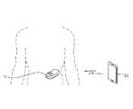
- FIG. 1is a schematic diagram illustrating a body-mounted continuous biometric information measurement system according to an embodiment of the present invention.
- the continuous biometric information measurement systemincludes a biometric information measurement device 10 and a communication terminal 30 .
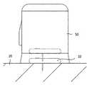
- FIG. 2is a view showing an applicator for attaching the biometric information measuring device of the present invention to the body.
- An adhesive tapemay be provided on the body contact surface of the biometric information measuring device 10 so that the biometric information measuring device 10 can be fixedly attached to the skin of the body. Therefore, when the applicator 50 is spaced apart from the skin of the body, the biometric information measuring device 10 is fixedly attached to the skin of the body by an adhesive tape.
- the biometric information measuring apparatusprovides an additional impedance to the sensor impedance of the sensor 100 to relatively suppress the noise level applied to the response signal generated by the sensor 100 when the sensor 100 is physically deformed. part 200 .
- the magnitude of the additional impedance of the load unit 200is larger than the magnitude of the sensor impedance of the sensor 100 .
- the load unit 200is characterized in that the resistance of 10K ⁇ to 10G ⁇ .
- a working electrode 130 and a counter electrode 150are formed at one end of the sensor.
- the load unit 1 201is connected only to the working electrode 130 , and the counter electrode 150 is separately connected to the working electrode 130 . do not connect the load of the , or connect the load part 2 203 only to the counter electrode 150 and connect a separate load to the working electrode 130 , or a load to each of the working electrode 130 and the counter electrode 150 .
- the part 1 201 and the load part 2 203may be connected.
- the sensor impedance of the sensor 100is in addition, an additional impedance that is relatively larger than the sensor impedance is connected to the sensor impedance, and thus, the effect of a change in the sensor impedance that changes according to the physical change of the sensor 100 in the overall impedance of the bioinformation measuring device is relatively small.
- the load unit 200may be manufactured by being provided inside the housing of the measuring unit 300 .
- the load unit 200is connected to the sensor 100 to provide additional impedance to the sensor impedance of the sensor 100, so that when the sensor is attached to the body and continuously generates a response signal, the sensor according to the physical load applied to the sensor It contributes to reduce the size of noise generated when the shape of the shape is deformed or moved. That is, the magnitude of the total impedance viewed from the measurement circuit unit 310 is the sum of the sensor impedance of the sensor 100 and the additional impedance of the load unit 200 , and the magnitude of the additional impedance is relatively larger than the magnitude of the sensor impedance. Therefore, even if the sensor impedance changes due to deformation or movement in the sensor, the contribution of the change in the sensor impedance to the overall impedance is small, and accordingly, the amount of noise generated in the response signal generated by the sensor can be reduced.
- the sensor 100includes a flexible base substrate 110 , a bioelectrode 130 disposed on one end of the base substrate 110 , and a conductive tracer formed on the upper surface of the base substrate 110 .
- a conductive tracemay be manufactured as the load unit 200 instead of a separate separate load unit.
- the bioelectrode 130 disposed on one end of the base substrate 110is inserted into the skin when the sensor is attached to the body to cause an electrochemical reaction inside the body, and generates a response signal. It is transmitted to the measurement circuitry 310 of 300 .
- the conductive traceris formed to have as small an impedance as possible.
- the conductive traceris intentionally made to have a relatively high impedance in order to operate the conductive tracer as the load unit 200 .
- the conductive tracermay be manufactured to have high impedance by changing the material, shape, width, length, etc. of the conductive tracer in order to have a high impedance to operate as a load part.
- FIG. 8is a view for explaining another example of the apparatus for measuring biometric information according to the present invention.
- the sensor 100 and the measurement unit 300are manufactured independently and are manufactured to be coupled to each other separately, and the sensor 100 and the measurement unit 300 include the sensor 100 and the Connection terminals 210 and 230 for electrically connecting the measurement unit 300 are formed. That is, the sensor 100 has a first connection terminal 210 formed at one end coupled to the measurement unit 300 , and the measurement unit 300 has a second connection electrically connected to the connection terminal 210 of the sensor. A terminal 230 is formed. The response signal generated from the bioelectrode of the sensor 100 is transmitted to the first connection terminal 210 through the conductive tracer, and the second connection terminal 230 electrically connected to the first connection terminal 210 responds. The signal is received and transmitted to the measurement circuit unit 310 .
- the load unit 200provides an additional impedance to the sensor impedance of the sensor 100, and when the sensor is attached to the body and continuously generates a response signal, the shape of the sensor is deformed or moved according to the physical load applied to the sensor. It contributes to reducing the size of the noise. That is, the magnitude of the total impedance viewed from the measurement circuit unit 310 is the sum of the sensor impedance of the sensor 100 and the additional impedance of the load unit 200 , and the magnitude of the additional impedance is relatively larger than the magnitude of the sensor impedance. Therefore, even if the sensor impedance changes due to deformation or movement in the sensor, the contribution of the change in the sensor impedance to the overall impedance is small, and accordingly, the amount of noise generated in the response signal generated by the sensor can be reduced.
- the power supply unit 310applies measurement power to the sensor, and the current-voltage converter 330 receives an analog current response signal from the sensor and converts it into a voltage measurement signal.
- the current-voltage converter 330may be an OPAMP.
- the biometric information generating unit 370converts an analog measurement signal to digital to generate biometric information.
- the size of the electrical load of the load unit 200that is, the size of the additional impedance changes according to the temperature of the load unit 200
- the temperature sensing unit 390detects the temperature of the load unit itself or the ambient temperature in which the load unit is disposed. It measures and provides information on the measured temperature to the biometric information generating unit 370 .
- the biometric information generator 370may determine the size of the additional impedance in consideration of the temperature of the load unit 200 based on the measured temperature, and accurately measure the biometric information from the response signal based on the determined size of the additional impedance. .
Landscapes
- Health & Medical Sciences (AREA)
- Life Sciences & Earth Sciences (AREA)
- Engineering & Computer Science (AREA)
- Physics & Mathematics (AREA)
- Molecular Biology (AREA)
- General Health & Medical Sciences (AREA)
- Veterinary Medicine (AREA)
- Public Health (AREA)
- Animal Behavior & Ethology (AREA)
- Biophysics (AREA)
- Pathology (AREA)
- Biomedical Technology (AREA)
- Heart & Thoracic Surgery (AREA)
- Medical Informatics (AREA)
- Surgery (AREA)
- Signal Processing (AREA)
- Optics & Photonics (AREA)
- Artificial Intelligence (AREA)
- Physiology (AREA)
- Computer Vision & Pattern Recognition (AREA)
- Psychiatry (AREA)
- Emergency Medicine (AREA)
- General Chemical & Material Sciences (AREA)
- Chemical Kinetics & Catalysis (AREA)
- Chemical & Material Sciences (AREA)
- Hematology (AREA)
- Measurement And Recording Of Electrical Phenomena And Electrical Characteristics Of The Living Body (AREA)
- Measurement Of The Respiration, Hearing Ability, Form, And Blood Characteristics Of Living Organisms (AREA)
- Measuring And Recording Apparatus For Diagnosis (AREA)
- Measuring Pulse, Heart Rate, Blood Pressure Or Blood Flow (AREA)
Abstract
Description
Translated fromKorean본 발명은 신체 부착형 생체정보의 측정장치에 관한 것으로, 보다 구체적으로 신체부착형 생체정보의 측정장치에서 센서에 추가 임피던스를 연결함으로써 센서의 변형이나 이동시 발생하는 노이즈의 크기를 줄여 생체 정보를 정확하게 측정할 수 있으며, 추가 임퍼던스를 통해 센서의 변형이나 이동시 응답신호에 영향을 주는 노이즈를 제거함으로써 정확하게 생체 정보를 측정할 수 있는 생체정보의 측정장치에 관한 것이다.The present invention relates to a body-mounted bio-information measuring device, and more specifically, by connecting an additional impedance to the sensor in the body-attached bio-information measuring device, the size of noise generated during deformation or movement of the sensor is reduced to accurately measure biometric information. It relates to an apparatus for measuring biometric information that can measure and accurately measure biometric information by removing noise that affects a response signal when a sensor is deformed or moved through additional impedance.
당뇨병은 전 세계적으로 주요 사망 원인 및 신체장애를 유발하는 요인이며, 그로 인해, 많은 사람들이 당뇨병으로 인해 건강상에 문제가 발생하고 있다. 특히, 당뇨병은, 심장 및 신장 질병, 실명, 신경손상 및 고혈압을 유발하는 심각한 질병이다. 장기간의 임상연구를 볼 때, 혈당치를 적당히 조절하는 것에 의해 합병증이 유발하는 것을 현저히 감소시킬 수 있다. 따라서 당뇨병은 지속적으로 관리하는 것이 중요한데, 중요한 요인은 혈당치를 자가 모니터링하는 것이다.Diabetes is the leading cause of death and disability worldwide, and as a result, many people suffer from health problems due to diabetes. In particular, diabetes is a serious disease that causes heart and kidney disease, blindness, nerve damage and high blood pressure. When looking at long-term clinical studies, it is possible to significantly reduce complications caused by moderately controlling blood sugar levels. Therefore, it is important to continuously manage diabetes, and an important factor is self-monitoring of blood sugar levels.
이러한 요구에 의해 사용자가 직접 사용자의 혈당을 검사할 수 있는 자가 혈당 측정기가 널리 보급되어 사용된다. 일반적인 혈당 측정기는 검사지인 센서 스트립에 사용자의 혈액을 묻혀 사용자의 혈당치를 측정한다. 즉, 혈액을 묻힌 센서 스트립을 혈당 측정기에 삽입하여 센서 스트립을 통해 측정된 혈당치를 혈당 측정기에서 표시한다.In response to this demand, a self-monitoring device capable of directly examining a user's blood sugar is widely used and widely used. A general blood glucose meter measures a user's blood glucose level by putting the user's blood on a sensor strip, which is a test strip. That is, the blood glucose level measured through the sensor strip is displayed on the blood glucose meter by inserting the sensor strip dipped in blood into the blood glucose meter.
이때, 채취된 혈액과 센서 스트립 내의 반응물질이 전기 화학적 반응에 의해 발생된 전기적 신호를 혈당 측정기가 수신하여, 혈당치를 측정한다. 이러한 채혈식 혈당기(finger prick method)는, 당뇨병 환자의 혈당 관리에 도움을 주지만, 측정 당시의 결과만 나타내기 때문에 자주 변화하는 혈당 수치를 정확하게 파악하는 것이 어려운 문제가 있다.At this time, the blood glucose meter receives an electrical signal generated by an electrochemical reaction between the collected blood and a reactant in the sensor strip, and measures the blood glucose level. Although such a finger prick method helps to manage blood sugar in diabetic patients, it is difficult to accurately identify frequently changing blood sugar levels because only the results at the time of measurement are shown.
당뇨병 환자는, 일반적으로 고혈당 및 저혈당 상태를 오가는데, 응급상황은 저혈당 상태에서 발생하고, 당분 공급이 오랫동안 지속되지 않으면, 의식을 잃거나 최악의 경우 목숨을 잃을 수도 있다. 따라서 저혈당 상태를 즉각적으로 발견하는 것은 당뇨병 환자에게 매우 중요하다. 하지만, 간헐적으로 혈당을 측정하는 채혈식 혈당 측정기는 분명한 한계가 있다.Diabetics typically switch between hyperglycemic and hypoglycemic states, but emergencies occur in hypoglycemic states, and if the sugar supply is not sustained for a long period of time, loss of consciousness or, in the worst case, death. Therefore, prompt detection of hypoglycemic conditions is very important for diabetic patients. However, there is a clear limit to the blood glucose meter that measures blood glucose intermittently.
이러한 채혈식 혈당 측정기의 한계를 극복하기 위해, 인체 내에 삽입하여 수분 간격으로 혈당을 측정하는 연속 혈당 측정 시스템(CGMS, Continuous Glucose Monitoring System)이 개발되었으며, 이를 이용하여 당뇨병 환자의 관리와 응급 상황에 용이하게 대처할 수 있다.In order to overcome the limitations of these blood-collecting blood glucose meters, a continuous glucose monitoring system (CGMS) has been developed that is inserted into the human body to measure blood glucose every few minutes. can be easily dealt with.
연속 혈당 측정 시스템은, 센서의 일부가 인체에 삽입된 상태에서 인체의 혈액과 같은 검사 물질을 채취하여 혈당 등의 생체 정보를 측정한다. 이를 위해 신체에 부착된 상태에서 생체 정보를 측정하는 센서트랜스미터와 센서트랜스미터로부터 측정된 생체 정보 데이터를 수신하는 통신 단말기를 포함한다.The continuous blood glucose measurement system measures biometric information such as blood glucose by collecting a test substance such as human blood while a part of a sensor is inserted into the human body. To this end, it includes a sensor transmitter that measures biometric information while attached to the body, and a communication terminal that receives biometric data measured from the sensor transmitter.
연속 혈당 측정용 센서트랜스미터와 같은 신체 부착형 생체 정보의 측정 장치에서 센서트랜스미터가 신체에 부착되고 센서의 일부가 인체에 삽입된 상태에서 혈당 정보에 대한 측정이 이루어지기 때문에, 사람이 움직일 때마다 센서 또는 센서가 삽입된 신체 주변 부위에 물리적인 힘이 가해져 센서가 변형되거나 이동하게 되는데, 이렇게 센서가 움직임에 따라 센서트랜스미터에서 측정된 생체 정보 데이터에 노이즈가 포함될 수 있으며 이로 인하여 센서트랜스미터에서 생성된 응답신호에 영향을 미쳐 생체 정보를 정확하게 측정할 수 없다는 문제점을 가진다.In a body-mounted biometric information measuring device such as a sensor transmitter for continuous blood glucose measurement, since the sensor transmitter is attached to the body and the blood glucose information is measured while a part of the sensor is inserted into the body, whenever a person moves, the sensor Alternatively, the sensor is deformed or moved by applying a physical force to the part around the body where the sensor is inserted. As the sensor moves, noise may be included in the biometric data measured by the sensor transmitter, resulting in the response generated by the sensor transmitter. There is a problem in that the biometric information cannot be accurately measured because it affects the signal.
본 발명은 위에서 언급한 종래 생체 정보의 측정 장치가 가지는 문제점을 해결하기 위한 것으로, 본 발명이 이루고자 하는 목적은 신체부착형 생체 정보의 측정 장치에서 센서의 변형이나 이동시 발생하는 노이즈의 크기를 줄여 생체 정보를 정확하게 측정할 수 있는 생체 정보의 측정 장치를 제공하는 것이다.SUMMARY OF THE INVENTION The present invention is to solve the problems of the conventional apparatus for measuring biometric information mentioned above, and an object of the present invention is to reduce the size of noise generated when a sensor is deformed or moved in a body-attached biometric information measuring device to reduce the size of the biometric information. An object of the present invention is to provide an apparatus for measuring biometric information capable of accurately measuring information.
본 발명이 이루고자 하는 다른 목적은 추가적으로 배치되는 전기적 부하를 통해 센서의 변형이나 이동시 응답신호에 영향을 주는 노이즈 크기를 줄이며 동시에 저주파 대역 통과 필터를 통해 고주파 성분의 노이즈를 포함한 응답신호에서 노이즈를 추가적으로 제거하여 정확하게 생체 정보를 측정할 수 있는 생체정보의 측정장치를 제공하는 것이다.Another object of the present invention is to reduce the noise level that affects the response signal when the sensor is deformed or moved through an additionally disposed electrical load, and at the same time, additionally removes noise from the response signal including the noise of the high-frequency component through the low-frequency band-pass filter. To provide a biometric information measuring device capable of accurately measuring biometric information.
본 발명이 이루고자 하는 또 다른 목적은 전기적 부하를 본 발명의 다양한 실시예에 따라 센서, 측정부 또는 센서와 측정부의 결합 위치에 형성하여 생체 정보를 정확하게 측정할 수 있는 생체 정보의 측정 장치를 제공하는 것이다.Another object of the present invention is to provide an apparatus for measuring biometric information that can accurately measure biometric information by forming an electrical load at a sensor, a measuring unit, or a combination position of a sensor and a measuring unit according to various embodiments of the present invention will be.
본 발명이 이루고자 하는 또 다른 목적은 전기적 부하의 온도 또는 전기적 부하의 주변 온도를 측정하고 온도에 따라 변화하는 부하부의 추가 임피던스를 고려하여 정확하게 생체 정보를 측정할 수 있는 생체 정보의 측정 장치를 제공하는 것이다.Another object of the present invention is to measure the temperature of the electrical load or the ambient temperature of the electrical load, and to provide a biometric information measuring device capable of accurately measuring the biometric information in consideration of the additional impedance of the load that changes according to the temperature will be.
본 발명의 목적을 달성하기 위하여 본 발명에 따른 생체 정보의 측정 장치는 피부에 삽입되는 생체 전극을 구비하는 센서와, 생체 전극으로 측정 전원을 인가하며 생체 전극으로부터 수신되는 응답 신호에 기초하여 생체 정보를 측정하는 측정부와, 센서의 센서 임피던스에 추가 임피던스를 제공하여 센서의 물리적 변형시 응답 신호에 가해지는 노이즈 크기를 상대적으로 억제하는 부하부를 포함하며, 추가 임피던스의 크기는 센서 임피던스의 크기보다 큰 것을 특징으로 한다.In order to achieve the object of the present invention, an apparatus for measuring biometric information according to the present invention includes a sensor including a bioelectrode inserted into the skin, and applying measurement power to the bioelectrode and biometric information based on a response signal received from the bioelectrode and a load unit that provides additional impedance to the sensor impedance of the sensor to relatively suppress the noise level applied to the response signal when the sensor is physically deformed, wherein the size of the additional impedance is larger than the size of the sensor impedance. characterized in that
여기서 생체 전극은 작동 전극과 기준전극을 포함하며, 부하부는 작동 전극에 직렬로 접속되거나 기준전극에 직렬로 접속되거나 작동 전극과 기준 전극에 각각 직렬로 접속되는 것을 특징으로 한다.Here, the bioelectrode includes a working electrode and a reference electrode, and the load part is connected to the working electrode in series, connected to the reference electrode in series, or connected to the working electrode and the reference electrode in series, respectively.
일 실시예에서 부하부는 측정부의 하우징 내부에 상기 생체 전극과 직렬로 배치되는 것을 특징으로 한다.In an embodiment, the load part is disposed in a housing of the measuring part in series with the bio-electrode.
다른 실시예에서 부하부는 센서의 몸체에 형성되어 생체 전극과 측정부를 전기적으로 연결하는 트레이서로 형성되는 것을 특징으로 한다.In another embodiment, the load part is formed as a tracer that is formed on the body of the sensor and electrically connects the bioelectrode and the measuring part.
또 다른 실시예에서 센서와 측정부는 서로 분리 가능하게 체결되는데, 부하부는 센서와 측정부를 체결시 센서와 측정부를 서로 전기적으로 접속시키는 접속 단자로 형성되는 것을 특징으로 한다.In another embodiment, the sensor and the measuring unit are detachably coupled to each other, and the load unit is formed as a connection terminal for electrically connecting the sensor and the measuring unit to each other when the sensor and the measuring unit are fastened.
여기서 측정부는 부하부에 의해 노이즈 크기가 억제된 응답 신호에서 고주파 대역의 노이즈를 필터링하는 저주파 통과 필터를 더 포함하는 것을 특징으로 한다.Here, the measurement unit is characterized in that it further includes a low-pass filter for filtering the noise of the high-frequency band from the response signal in which the noise level is suppressed by the load unit.
여기서 부하부는 10KΩ 내지 10GΩ의 저항인 것을 특징으로 한다.Here, the load part is characterized in that the resistance of 10KΩ to 10GΩ.
바람직하게 측정부는 부하부의 온도 또는 부하부 주변의 온도를 측정하는 온도 센서를 더 포함하며, 온도 센서를 통해 측정한 온도에 따라 변화하는 부하부의 추가 임피던스를 고려하여 응답신호로부터 생체 정보를 측정하는 것을 특징으로 한다.Preferably, the measuring unit further includes a temperature sensor for measuring the temperature of the load unit or the temperature around the load unit, and measuring biometric information from the response signal in consideration of the additional impedance of the load unit that changes according to the temperature measured through the temperature sensor characterized.
본 발명에 따른 생체 정보의 측정 장치는 다음과 같은 효과를 가진다.The apparatus for measuring biometric information according to the present invention has the following effects.
첫째, 본 발명에 따른 생체 정보의 측정 장치는 신체부착형 생체 정보의 측정 장치에서 센서 임피던스에 추가 임피던스를 연결함으로써, 센서의 변형이나 이동시 발생하는 노이즈의 크기를 줄여 생체 정보를 정확하게 측정할 수 있다.First, the apparatus for measuring biometric information according to the present invention can accurately measure biometric information by connecting an additional impedance to the sensor impedance in the body-mountable biometric information measuring device, thereby reducing the amount of noise generated when the sensor is deformed or moved. .
둘째, 본 발명에 따른 생체 정보의 측정 장치는 추가적으로 배치되는 전기적 부하를 통해 센서의 변형이나 이동시 응답신호에 영향을 주는 노이즈 크기를 줄이며 동시에 저주파 대역 통과 필터를 통해 고주파 성분의 노이즈를 포함한 응답신호에서 노이즈를 추가적으로 제거함으로써, 정확하게 생체 정보를 측정할 수 있다.Second, the device for measuring biometric information according to the present invention reduces the noise level affecting the response signal when the sensor is deformed or moved through an additionally disposed electrical load, and at the same time, through a low-frequency bandpass filter, in the response signal including noise of high-frequency components. By additionally removing noise, biometric information can be accurately measured.
셋째, 본 발명에 따른 생체 정보의 측정 장치는 전기적 부하를 센서, 측정부 또는 센서와 측정부의 결합 위치에 형성함으로써, 다양한 실시예에 따라 생체 정보를 정확하게 측정할 수 있는 생체 정보의 측정 장치를 용이하게 제조할 수 있다.Third, the apparatus for measuring biometric information according to the present invention forms an electrical load at a sensor, a measuring unit, or a combined position of a sensor and a measuring unit, so that the biometric information measuring device capable of accurately measuring biometric information according to various embodiments is facilitated can be manufactured.
도 1은 본 발명의 일 실시예에 따른 연속 생체정보 측정 시스템을 도시한 개략도이다.1 is a schematic diagram illustrating a continuous biometric information measurement system according to an embodiment of the present invention.
도 2는 본 발명의 생체정보 측정장치를 신체에 부착하기 위한 어플리케이터를 도시한 도면이다.Figure 2 is a view showing an applicator for attaching the biometric information measuring device of the present invention to the body.
도 3은 센서의 랜들(Randle) 등가회로를 설명하기 위한 도면이다.3 is a diagram for explaining a Randle equivalent circuit of a sensor.
도 4는 본 발명에 따라 센서의 움직임으로 발생하는 노이즈의 크기를 줄이는 생체정보 측정장치를 설명하기 위한 기능 블록도이다.4 is a functional block diagram for explaining an apparatus for measuring biometric information that reduces the size of noise generated by movement of a sensor according to the present invention.
도 5는 본 발명에 따른 생체정보 측정장치에서 부하를 연결하는 일 예를 설명하기 위한 도면이다.5 is a view for explaining an example of connecting a load in the apparatus for measuring biometric information according to the present invention.
도 6은 본 발명에 따른 생체전극 측정장치의 일 예를 설명하기 위한 도면이다.6 is a view for explaining an example of a bioelectrode measuring apparatus according to the present invention.
도 7은 본 발명에 따른 생체정보 측정장치의 다른 예를 설명하기 위한 도면이다.7 is a view for explaining another example of the apparatus for measuring biometric information according to the present invention.
도 8은 본 발명에 따른 생체정보 측정장치의 또 다른 예를 설명하기 위한 도면이다.8 is a view for explaining another example of the apparatus for measuring biometric information according to the present invention.
도 9는 본 발명에 따른 생체정보 측정장치의 또 다른 예를 설명하기 위한 도면이다.9 is a view for explaining another example of the apparatus for measuring biometric information according to the present invention.
본 발명에서 사용되는 기술적 용어는 단지 특정한 실시 예를 설명하기 위해 사용된 것으로, 본 발명을 한정하려는 의도가 아님을 유의해야 한다. 또한, 본 발명에서 사용되는 기술적 용어는 본 발명에서 특별히 다른 의미로 정의되지 않는 한, 본 발명이 속하는 기술 분야에서 통상의 지식을 가진 자에 의해 일반적으로 이해되는 의미로 해석되어야 하며, 과도하게 포괄적인 의미로 해석되거나, 과도하게 축소된 의미로 해석되지 않아야 한다. 또한, 본 발명에서 사용되는 기술적인 용어가 본 발명의 사상을 정확하게 표현하지 못하는 잘못된 기술적 용어일 때에는, 당업자가 올바르게 이해할 수 있는 기술적 용어로 대체되어 이해되어야 할 것이다.It should be noted that the technical terms used in the present invention are only used to describe specific embodiments, and are not intended to limit the present invention. In addition, the technical terms used in the present invention should be interpreted as meanings generally understood by those of ordinary skill in the art to which the present invention belongs, unless otherwise defined in particular in the present invention, and excessively comprehensive It should not be construed in the meaning of a human being or in an excessively reduced meaning. In addition, when the technical term used in the present invention is an incorrect technical term that does not accurately express the spirit of the present invention, it should be understood by being replaced with a technical term that can be correctly understood by those skilled in the art.
또한, 본 발명에서 사용되는 단수의 표현은 문맥상 명백하게 다르게 뜻하지 않는 한 복수의 표현을 포함한다. 본 발명에서, "구성된다" 또는 "포함한다" 등의 용어는 발명에 기재된 여러 구성 요소들, 또는 여러 단계를 반드시 모두 포함하는 것으로 해석되지 않아야 하며, 그 중 일부 구성 요소들 또는 일부 단계들은 포함되지 않을 수도 있고, 또는 추가적인 구성 요소 또는 단계들을 더 포함할 수 있는 것으로 해석되어야 한다.Also, as used herein, the singular expression includes the plural expression unless the context clearly dictates otherwise. In the present invention, terms such as "consisting of" or "comprising" should not be construed as necessarily including all of the various elements or several steps described in the invention, some of which elements or some steps are included. It should be construed that it may not, or may further include additional components or steps.
또한, 첨부된 도면은 본 발명의 사상을 쉽게 이해할 수 있도록 하기 위한 것일 뿐, 첨부된 도면에 의해 본 발명의 사상이 제한되는 것으로 해석되어서는 아니됨을 유의해야 한다.In addition, it should be noted that the accompanying drawings are only for easy understanding of the spirit of the present invention, and should not be construed as limiting the spirit of the present invention by the accompanying drawings.
이하 첨부한 도면을 참고로 본 발명에 따른 신체부착형 생체정보의 측정장치에 대해 보다 구체적으로 살펴본다.Hereinafter, a body-mountable biometric information measuring device according to the present invention will be described in more detail with reference to the accompanying drawings.
도 1은 본 발명의 일 실시예에 따른 신체부착형 연속 생체정보 측정 시스템을 도시한 개략도이다.1 is a schematic diagram illustrating a body-mounted continuous biometric information measurement system according to an embodiment of the present invention.
도 1을 참조하면, 본 발명의 일 실시예에 따른 연속 생체정보 측정 시스템은 생체정보 측정장치(10) 및 통신 단말기(30)를 포함한다.Referring to FIG. 1 , the continuous biometric information measurement system according to an embodiment of the present invention includes a biometric
생체정보 측정장치(10)는 신체에 삽입되는 생체 전극을 구비하는 센서와 생체 전극으로부터 수신하는 응답신호에 기초하여 생체정보를 측정하는 측정부를 포함한다. 생체정보 측정장치(10)가 신체에 부착시 센서의 생체 전극은 피부에 삽입되어 전기화학 반응을 일으키며 응답신호를 생성하고 측정부는 응답신호에 기초하여 혈당 등의 생체정보를 측정한다. 측정부는 측정한 생체정보를 실시간으로 또는 주기적으로 또는 통신 단말기가 요청하는 경우 통신 단말기로 송신한다.The
여기서 센서와 측정부는 일체형으로 제조될 수 있으나 센서와 측정부는 서로 분리 체결 가능하도록 제조될 수 있다. 센서와 측정부가 서로 분리 체결 가능하도록 제조되는 경우 센서와 측정부는 전기적으로 서로 접촉하는 접속 단자를 구비하며, 접속 단자를 통해 센서에서 생성한 응답신호를 측정부로 제공한다.Here, the sensor and the measuring unit may be manufactured integrally, but the sensor and the measuring unit may be manufactured to be separately coupled to each other. When the sensor and the measurement unit are manufactured to be separately coupled to each other, the sensor and the measurement unit have connection terminals that electrically contact each other, and provide a response signal generated by the sensor to the measurement unit through the connection terminal.
통신 단말기(30)는 생체정보 측정장치(10)로부터 생체 정보를 수신하고 수신한 생체 정보를 사용자에 표시할 수 있는 단말기로, 스마트폰, 태블릿 PC, 또는 노트북 등과 같이 생체정보 측정장치(10)와 통신할 수 있는 이동 단말기가 이용될 수 있다. 물론, 통신 단말기(30)는 이에 한정되는 것은 아니며, 통신 기능을 포함하고 프로그램이나 어플리케이션이 설치될 수 있는 단말기이면 어떤 종류의 단말기일 수 있다.The
생체정보 측정장치(10)는 통신 단말기(30)의 요청에 의해 또는 설정된 시각마다 주기적으로 측정한 생체정보를 통신 단말기(30)로 전송하는데, 생체정보 측정장치(10)와 통신 단말기(30) 사이에서 데이터 통신을 위해 생체정보 측정장치(10)와 통신 단말기(30)는 서로 USB 케이블 등에 의해 유선으로 통신 연결되거나 또는 적외선 통신, NFC 통신, 블루투스 등의 무선 통신 방식으로 통신 연결될 수 있다.The biometric
여기서 생체정보 측정장치는 어플리케이터를 통해 신체 일부에 부착되는데, 도 2는 본 발명의 생체정보 측정장치를 신체에 부착하기 위한 어플리케이터를 도시한 도면이다.Here, the biometric information measuring device is attached to a part of the body through an applicator, and FIG. 2 is a view showing an applicator for attaching the biometric information measuring device of the present invention to the body.
도 2를 참고로 어플리케이터(50)에 대해 살펴보면, 어플리케이터(50)는, 생체정보 측정장치(10)를 내부에 구비하며 사용자의 조작으로 생체정보 측정장치(10)를 외부로 토출하여 사용자의 특정 신체 부위에 부착시키도록 작동한다. 어플리케이터(50)는 일면이 개방된 형상으로 형성되어 있는데, 생체정보 측정장치(10)는 어플리케이터(50)의 개방된 일면을 통해 어플리케이터(50)에 설치된다.Looking at the
어플리케이터(50)를 이용하여 생체정보 측정장치(10)를 신체 일부에 부착 시, 생체정보 측정장치(10)에 구비된 센서의 일단을 피부(20)에 삽입하기 위해 어플리케이터(50)는 센서의 일단을 내부에 감싸도록 형성된 니들(미도시), 니들과 센서 일단을 함께 피부로 밀어내는 제1 탄성 부재(미도시), 니들만을 인출하기 위한 제2 탄성 부재(미도시)를 구비하고 있다. 이러한 어플리케이터(50)의 구성을 통해 어플리케이터(50) 내부에 압축된 상태로 배치된 제1 탄성 부재(미도시)의 압축 해지로 니들과 센서 일단을 동시에 피부에 삽입하며, 센서 일단이 피부에 삽입 시 압축된 제2 탄성부재(미도시)의 압축 해지에 의해 니들만을 인출한다. 사용자는 어플리케이터(50)를 통해 안전하고 용이하게 생체정보 측정장치(10)를 피부에 부착시킬 수 있다.When attaching the biometric
생체정보 측정장치(10)의 신체 접촉면에는 생체정보 측정장치(10)가 신체의 피부에 고정 부착될 수 있게 접착테이프가 구비될 수 있다. 따라서 어플리케이터(50)를 신체의 피부에서 이격시키면 접착테이프에 의해 생체정보 측정장치(10)는 신체의 피부에 고정 부착된 상태가 된다. An adhesive tape may be provided on the body contact surface of the biometric
이후 생체정보 측정장치(10)에 전원이 인가되면 생체정보 측정장치(10)는 통신 단말기(30)와 통신을 연결하며, 생체정보 측정장치(10)는 측정한 생체 정보를 통신 단말기(30)로 전송하게 된다.After that, when power is applied to the biometric
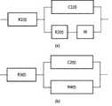
도 3은 센서의 랜들(Randles) 등가회로를 설명하기 위한 도면이다. 도 3(a)에 도시되어 있는 바와 같이 랜들 등가회로는 생체 전극과 전해액, 즉 체액 계면에서 일어나는 전기화학 반응을 전기회로로 모델링한 것으로, R1(t)는 체액의 저항, C1(t)는 전기이중층에 의한 캐패시턴스, R2(t)는 전하전달저항 그리고 W는 와버그임피던스를 나타낸다.3 is a diagram for explaining an equivalent circuit of Randles of a sensor. As shown in Fig. 3(a), the Randall equivalent circuit is a model of an electrochemical reaction occurring at the interface between a bioelectrode and an electrolyte, that is, a bodily fluid, where R1(t) is the resistance of the body fluid, and C1(t) is The capacitance of the electric double layer, R2(t) is the charge transfer resistance, and W is the Warburg impedance.
도 3(b)에 도시되어 있는 바와 같이 이온의 이동 경로에 막이 존재하는 경우 랜들 등가회로를 살펴보면, 저항, 커패시턴스 등의 임피던스 총합이 센서 임피던스이다. 인체 삽입형 센서에서는 전기화학반응이 일어나는 전극이 센서에 그대로 노출되는 것이 아니라, 대상물질의 확산속도를 제어하는 확산막과 생체 면역반응을 억제하는 생체적합성 보호막 등이 센서 주위를 둘러쌓인 구조를 가지게 된다. 이러한 막들은 랜들 회로에서 체액의 저항에 해당하는 R1(t) 위치에 직렬로 추가될 수 있다. 이러한 막은 저항과 커패시터의 병렬 구조로 해석하는 것이 일반적이다. 센서가 외력을 받아 노이즈가 발생하는 많은 경우 중 하나가 도3에 표시된 등가회로의 성분들이 변화하는 것이다.As shown in FIG. 3(b), if a film exists in the movement path of ions, looking at the Randall equivalent circuit, the sum of impedances such as resistance and capacitance is the sensor impedance. In the human body implantable sensor, the electrode where the electrochemical reaction occurs is not directly exposed to the sensor, but a diffusion membrane that controls the diffusion rate of the target material and a biocompatible protective layer that suppresses the biological immune response has a structure surrounding the sensor. . These films can be added in series at the R1(t) position, which corresponds to the resistance of the body fluid in the randle circuit. It is common to interpret such a film as a parallel structure of a resistor and a capacitor. One of the many cases in which the sensor receives external force and generates noise is that the components of the equivalent circuit shown in FIG. 3 change.
특히, 등가회로의 R1, R3, R4, C2에 해당하는 구성성분들이 순간적으로 변화하게 되면, 센서의 충전전류의 변화를 유발하여, 응답신호가 순간적으로 변화하게 된다.In particular, when the components corresponding to R1, R3, R4, and C2 of the equivalent circuit change instantaneously, a change in the charging current of the sensor is induced, and the response signal changes instantaneously.
생체정보 측정장치(10)가 신체에 부착되고 센서의 생체 전극이 신체에 삽입된 상태에서 생체정보에 대한 측정이 이루어지기 때문에, 사용자가 움직일 때마다 센서 또는 센서가 삽입된 신체 주변 부위에 물리적인 힘이 가해져 센서가 변형되거나 이동하게 되는데, 이러한 과정에서 센서의 등가회로로 표현되는 임피던스 성분들이 외력에 의해 변화게 되며 임피던스 성분의 변화에 따라 센서에서 생성된 응답신호에 노이즈가 포함될 수 있는데, 이와 같이 노이즈가 포함된 응답신호로부터 생체 정보를 측정하는 경우 사용자의 생체 정보를 정확하게 측정할 수 없게 된다.Since the biometric
도 4는 본 발명에 따라 센서의 움직임으로 발생하는 노이즈의 크기를 줄이는 생체정보 측정장치를 설명하기 위한 기능 블록도이다.4 is a functional block diagram for explaining an apparatus for measuring biometric information that reduces the size of noise generated by movement of a sensor according to the present invention.
도 4를 참고로 보다 구체적으로 살펴보면, 센서(100)는 생체 전극이 형성되어 있는데 생체 전극은 신체에 삽입되어 산화환원 반응을 일으키며 응답 신호를 생성한다. 측정부(300)는 센서(100)의 생체 전극으로 측정 전원을 제공하며 센서(100)의 생체 전극으로부터 수신되는 응답 신호에 기초하여 생체 정보를 측정한다. 측정부(300)는 통신부를 구비하여 통신 단말기와 통신하는데, 측정부(300)는 측정한 생체 정보를 실시간으로 또는 통신 단말기가 요청하는 경우 통신부를 통해 통신 단말기로 송신한다.Referring to FIG. 4 in more detail, the
본 발명에 따른 생체정보 측정장치는 센서(100)의 센서 임피던스에 추가 임피던스를 제공하여 센서(100)의 물리적 변형시 센서(100)에서 생성되는 응답 신호에 가해지는 노이즈 크기를 상대적으로 억제하는 부하부(200)를 포함한다. 여기서 부하부(200)의 추가 임피던스의 크기는 센서(100)가 가지는 센서 임피던스의 크기보다 큰 것을 특징으로 한다. 바람직하게 부하부(200)는 10KΩ 내지 10GΩ의 저항인 것을 특징으로 한다.The biometric information measuring apparatus according to the present invention provides an additional impedance to the sensor impedance of the
이와 같이 부하부(200)를 이용하여 센서(100)가 가지는 센서 임피던스에 더하여 센서 임피던스보다 상대적으로 큰 추가 임피던스를 센서 임피던스에 연결함으로써, 생체정보 측정장치의 전체적인 임피던스에서 센서(100)의 물리적 변화에 따라 변화하는 센서 임피던스의 변화 영향은 상대적으로 작아지며 이로 인하여 센서(100)에 물리적 변형이 발생하더라도 생성되는 응답 신호에 가해지는 노이즈의 크기는 줄어들게 된다.In this way, by using the
도 5에 도시되어 있는 바와 같이, 센서의 일단에는 작동 전극(130)과 상대 전극(150)이 형성되어 있는데 작동 전극(130)에만 부하부1(201)를 연결하고 상대 전극(150)에는 별도의 부하를 연결하지 않거나, 상대 전극(150)에만 부하부2(203)를 연결하고 작동 전극(130)에는 별도의 부하를 연결하지 않거나, 작동 전극(130)과 상대 전극(150) 각각에 부하부1(201)와 부하부2(203)을 연결할 수 있다. 이와 같이, 작동 전극(130)에만 부하를 연결하거나 상대 전극(150)에만 부하를 연결하거나 작동 전극(130)과 상대 전극(150)에 분리하여 각각 부하를 연결하더라도 센서(100)가 가지는 센서 임피던스에 더하여 센서 임피던스보다 상대적으로 큰 추가 임피던스를 센서 임피던스에 연결하게 되며, 이로 인하여 생체정보 측정장치의 전체적인 임피던스에서 센서(100)의 물리적 변화에 따라 변화하는 센서 임피던스의 변화 영향은 상대적으로 작아진다.As shown in FIG. 5 , a working
도 6은 본 발명에 따른 생체전극 측정장치의 일 예를 설명하기 위한 도면이다.6 is a view for explaining an example of a bioelectrode measuring apparatus according to the present invention.
도 6을 참고로 보다 구체적으로 살펴보면, 부하부(200)는 측정부(300)의 하우징 내부에 구비되어 제작될 수 있다.Referring to FIG. 6 in more detail, the
센서(100)는 플렉서블한 베이스 기판(110), 베이스 기판(110)의 일단에 배치되는 생체 전극(130) 및 베이스 기판(110)의 상면에 형성된 전도성 트레이서(150)를 구비하고 있다. 베이스 기판(110)의 일단에 배치된 생체 전극(130)은 센서가 신체에 부착시 피부에 삽입되어 신체 내부에서 전기화학 반응을 일으키며 응답신호를 생성하고, 생성한 응답신호는 전도성 트레이서(150)를 따라 측정부(300)의 측정 회로부(310)로 전달된다. 여기서 측정 회로부(310)는 생체 전극(130)으로 측정 전원을 제공하며 측정 전원에 따라 생체 전극에서 전기화학 반응에 따른 응답신호를 수신하여 사용자의 생체 정보를 측정하는데, 측정 회로부(310)는 측정한 생체 정보를 내부 메모리에 저장하거나 통신 단말기로 송신한다.The
부하부(200)는 센서(100)에 연결되어 센서(100)가 가지는 센서 임피던스에 추가 임피던스를 제공하여, 센서가 신체에 부착되어 연속하여 응답신호를 생성시 센서에 가해지는 물리적 부하에 따라 센서의 형태가 변형되거나 이동시 발생하는 노이즈의 크기를 줄이도록 기여한다. 즉, 측정 회로부(310) 측에서 바라본 전체 임피던스의 크기는 센서(100)의 센서 임피던스와 부하부(200)의 추가 임피던스의 합이며 추가 임피던스의 크기는 센서 임피던스의 크기보다 상대적으로 크다. 따라서 센서에 변형이 일어나거나 움직임이 발생하여 센서 임피던스가 변하더라도 전체 임피던스에서 센서 임피던스의 변화 기여도는 작게되고 이에 따라 센서에서 생성된 응답신호에 발생하는 노이즈의 크기를 줄일 수 있다.The
도 7은 본 발명에 따른 생체정보 측정장치의 다른 예를 설명하기 위한 도면이다.7 is a view for explaining another example of the apparatus for measuring biometric information according to the present invention.
도 7을 참고로 보다 구체적으로 살펴보면, 부하부(200)는 센서(100)의 전도성 트레이서로 제작될 수 있다.Referring to FIG. 7 in more detail, the
센서(100)는 플렉서블한 베이스 기판(110), 베이스 기판(110)의 일단에 배치되는 생체 전극(130) 및 베이스 기판(110)의 상면에 형성된 전도성 트레이서를 구비하는데, 본 발명에 따른 생체정보 측정장치의 다른 예에서는 별도의 분리된 부하부를 구비하는 대신 전도성 트레이스를 부하부(200)로 제작할 수 있다. 베이스 기판(110)의 일단에 배치된 생체 전극(130)은 센서가 신체에 부착시 피부에 삽입되어 신체 내부에서 전기화학 반응을 일으키며 응답신호를 생성하고 생성한 응답신호는 전도성 트레이서를 따라 측정부(300)의 측정 회로부(310)로 전달된다.The
통상적으로 전도성 트레이서는 가능한 작은 임피던스를 가지도록 형성되는데, 본 발명에 따른 생체정보 측정장치의 다른 예에서는 전도성 트레이서를 부하부(200)로 동작하기 위하여 의도적으로 전도성 트레이서가 상대적으로 높은 임피던스를 가지도록 제작한다. 바람직하게 전도성 트레이서가 부하부로 동작하도록 높은 임피던스를 가지기 위하여, 전도성 트레이서의 재질, 형태, 폭, 길이 등을 변경하여 높은 임피던스를 가지도록 제작할 수 있다.In general, the conductive tracer is formed to have as small an impedance as possible. In another example of the biometric information measuring device according to the present invention, the conductive tracer is intentionally made to have a relatively high impedance in order to operate the conductive tracer as the
부하부(200)는 센서(100)가 가지는 센서 임피던스에 추가 임피던스를 제공하여, 센서가 신체에 부착되어 연속하여 응답신호를 생성시 센서에 가해지는 물리적 부하에 따라 센서의 형태가 변형되거나 이동시 발생하는 노이즈의 크기를 줄이도록 기여한다. 즉, 측정 회로부(310) 측에서 바라본 전체 임피던스의 크기는 센서(100)의 센서 임피던스와 부하부(200)의 추가 임피던스의 합이며 추가 임피던스의 크기는 센서 임피던스의 크기보다 상대적으로 크다. 따라서 센서에 변형이 일어나거나 움직임이 발생하여 센서 임피던스가 변하더라도 전체 임피던스에서 센서 임피던스의 변화 기여도는 작게되고 이에 따라 센서에서 생성된 응답신호에 발생하는 노이즈의 크기를 줄일 수 있다.The
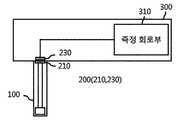
도 8은 본 발명에 따른 생체정보 측정장치의 또 다른 예를 설명하기 위한 도면이다.8 is a view for explaining another example of the apparatus for measuring biometric information according to the present invention.
도 8을 참고로 보다 구체적으로 살펴보면, 센서(100)와 측정부(300)는 독립적으로 제작되어 서로 분리 체결되도록 제작되는데, 센서(100)와 측정부(300)에는 체결시 센서(100)와 측정부(300)를 전기적으로 접속시키는 접속 단자(210, 230)가 형성되어 있다. 즉 센서(100)에는 측정부(300)와 결합되는 일단에 제1 접속 단자(210)가 형성되어 있으며, 측정부(300)에는 센서의 접속 단자(210)에 서로 전기적으로 접속되는 제2 접속 단자(230)가 형성되어 있다. 센서(100)의 생체 전극에서 생성된 응답 신호는 전도성 트레이서를 통해 제1 접속 단자(210)로 전달되며, 제1 접속 단자(210)와 전기적으로 접속되어 있는 제2 접속 단자(230)는 응답 신호를 수신하여 측정 회로부(310)로 전달한다.Referring to FIG. 8 in more detail, the
통상적으로 접속 단자는 임피던스가 낮은 전도성 탄성체를 이용하는데, 본 발명에 따른 생체정보 측정장치의 또 다른 예에서 접속 단자(210, 230)를 부하부(200)로 동작하기 위하여 의도적으로 접속 단자가 상대적으로 높은 임피던스를 가지도록 제작한다. 바람직하게 접속 단자(210, 230)가 부하부로 동작하도록 높은 임피던스를 가지기 위하여, 접속 단자(210, 230)의 재질, 형태, 폭 등을 변경하여 높은 임피던스를 가지도록 제작할 수 있다.Typically, the connection terminal uses a low impedance conductive elastic body. In another example of the biometric information measuring device according to the present invention, in order to operate the
부하부(200)는 센서(100)가 가지는 센서 임피던스에 추가 임피던스를 제공하여, 센서가 신체에 부착되어 연속하여 응답신호를 생성시 센서에 가해지는 물리적 부하에 따라 센서의 형태가 변형되거나 이동시 발생하는 노이즈의 크기를 줄이도록 기여한다. 즉, 측정 회로부(310) 측에서 바라본 전체 임피던스의 크기는 센서(100)의 센서 임피던스와 부하부(200)의 추가 임피던스의 합이며 추가 임피던스의 크기는 센서 임피던스의 크기보다 상대적으로 크다. 따라서 센서에 변형이 일어나거나 움직임이 발생하여 센서 임피던스가 변하더라도 전체 임피던스에서 센서 임피던스의 변화 기여도는 작게되고 이에 따라 센서에서 생성된 응답신호에 발생하는 노이즈의 크기를 줄일 수 있다.The
도 9는 본 발명에 따른 생체정보 측정장치의 또 다른 예를 설명하기 위한 도면이다.9 is a view for explaining another example of the apparatus for measuring biometric information according to the present invention.
도 9를 참고로 보다 구체적으로 살펴보면, 측정부(300)는 전원부(310), 전류-전압 변환부(330), 생체 정보 생성부(370) 및 온도 감지부(390)를 포함하고 있다.Referring to FIG. 9 in more detail, the
전원부(310)는 센서로 측정전원을 인가하며 전류-전압 변환부(330)는 센서로부터 아날로그의 전류 응답신호를 받아 전압으로 측정신호로 변환한다. 여기서 전류-전압 변환부(330)는 OPAMP가 사용될 수 있다. 생체 정보 생성부(370)는 아날로그의 측정신호를 디지털로 변환하여 생체 정보를 생성한다. 부하부(200)의 전기적 부하의 크기, 즉 추가 임피던스의 크기는 부하부(200)의 온도에 따라 변하게 되는데, 온도 감지부(390)는 부하부 자체의 온도 또는 부하부가 배치되어 있는 주변 온도를 측정하고 측정한 온도에 대한 정보를 생체 정보 생성부(370)로 제공한다. 생체 정보 생성부(370)는 측정한 온도에 기초하여 부하부(200)의 온도를 고려하여 추가 임피던스의 크기를 판단하며 판단한 추가 임피던스의 크기에 기초하여 응답 신호로부터 정확하게 생체 정보를 측정할 수 있다.The
앞서 도 5 내지 도 8을 참고로 설명한 측정 회로부는 전원부(310), 전류-전압 변환부(330), 생체 정보 생성부(370) 및 온도 감지부(390)를 구비하여 동일하게 동작할 수 있다.The measurement circuit unit described above with reference to FIGS. 5 to 8 includes a
바람직하게, 본 발명에 따른 생체정보 측정장치의 또 다른 예는 필터부(350)를 더 포함하는데, 필터부(350)는 저주파 대역 통과 필터로 전압으로 변환한 측정신호를 필터링하여 측정신호에서 고주파 성분의 노이즈를 제거한다.Preferably, another example of the apparatus for measuring biometric information according to the present invention further includes a
즉, 도 9를 참고로 설명하는 본 발명에 따른 생체정보 측정장치는 추가적으로 필터부(350)를 더 포함하는데, 부하부(200)를 통해 센서 임피던스에 추가 임피던스를 합하여 센서 임피던스가 변하더라도 전체 임피던스에서 센서 임피던스의 변화 기여도를 작게하도록 하여 전류-전압 변환부(330)로 인가되는 전류 응답신호에서 노이즈의 크기를 줄이고, 추가적으로 필터부(350)를 통해 변환한 측정 신호에서 고주파 성분의 노이즈를 제거함으로써 보다 정확하게 생체 정보를 측정할 수 있다. 더욱이 전류-전압 변환부(330)로 OPAMP를 사용하는데 부하부(200)를 통해 노이즈 크기가 감쇄된 전류 응답신호를 전류-전압 변환부(330)에서 증폭하여 전압 측정신호를 생성함으로써, 부하부(200)와 필터부(350)의 조합을 통해 전류-전압 변환부(330)의 증폭율을 높여 측정 범위를 줄일 수 있으며 단순히 필터부(350)만을 사용하는 것보다 노이즈에 영향을 덜 받아 정확하게 생체 정보를 측정할 수 있다.That is, the apparatus for measuring biometric information according to the present invention described with reference to FIG. 9 further includes a
본 발명은 도면에 도시된 실시예를 참고로 설명되었으나 이는 예시적인 것에 불과하며, 본 기술 분야의 통상의 지식을 가진 자라면 이로부터 다양한 변형 및 균등한 타 실시예가 가능하다는 점을 이해할 것이다. 따라서, 본 발명의 진정한 기술적 보호 범위는 첨부된 등록청구범위의 기술적 사상에 의해 정해져야 할 것이다.Although the present invention has been described with reference to the embodiment shown in the drawings, which is merely exemplary, those skilled in the art will understand that various modifications and equivalent other embodiments are possible therefrom. Accordingly, the true technical protection scope of the present invention should be determined by the technical spirit of the appended claims.
Claims (8)
Translated fromKoreanPriority Applications (5)
| Application Number | Priority Date | Filing Date | Title |
|---|---|---|---|
| AU2021257283AAU2021257283A1 (en) | 2020-04-13 | 2021-03-16 | Apparatus for measuring biometric information |
| JP2022552913AJP7650285B2 (en) | 2020-04-13 | 2021-03-16 | Biological information measuring device |
| US17/909,375US20230148913A1 (en) | 2020-04-13 | 2021-03-16 | Apparatus for measuring biometric information |
| EP21789098.7AEP4098192B1 (en) | 2020-04-13 | 2021-03-16 | Apparatus for measuring biometric information |
| CN202180017147.XACN115175610A (en) | 2020-04-13 | 2021-03-16 | Biological information measuring device |
Applications Claiming Priority (2)
| Application Number | Priority Date | Filing Date | Title |
|---|---|---|---|
| KR1020200044830AKR102353059B1 (en) | 2020-04-13 | 2020-04-13 | Apparatus for measuring biometric data |
| KR10-2020-0044830 | 2020-04-13 |
Publications (1)
| Publication Number | Publication Date |
|---|---|
| WO2021210792A1true WO2021210792A1 (en) | 2021-10-21 |
Family
ID=78084937
Family Applications (1)
| Application Number | Title | Priority Date | Filing Date |
|---|---|---|---|
| PCT/KR2021/003225CeasedWO2021210792A1 (en) | 2020-04-13 | 2021-03-16 | Apparatus for measuring biometric information |
Country Status (7)
| Country | Link |
|---|---|
| US (1) | US20230148913A1 (en) |
| EP (1) | EP4098192B1 (en) |
| JP (1) | JP7650285B2 (en) |
| KR (1) | KR102353059B1 (en) |
| CN (1) | CN115175610A (en) |
| AU (1) | AU2021257283A1 (en) |
| WO (1) | WO2021210792A1 (en) |
Cited By (1)
| Publication number | Priority date | Publication date | Assignee | Title |
|---|---|---|---|---|
| FR3138998A1 (en)* | 2022-08-26 | 2024-03-01 | Pkvitality | Correction of the measurement of an analyte concentration |
Citations (5)
| Publication number | Priority date | Publication date | Assignee | Title |
|---|---|---|---|---|
| US5704365A (en)* | 1994-11-14 | 1998-01-06 | Cambridge Heart, Inc. | Using related signals to reduce ECG noise |
| KR20130022542A (en)* | 2011-08-25 | 2013-03-07 | 삼성전자주식회사 | Apparatus and method for measuring bioelectic signals |
| KR20140094912A (en)* | 2013-01-23 | 2014-07-31 | 동국대학교 산학협력단 | Multi bio signal sensor |
| KR20150001225A (en)* | 2013-06-26 | 2015-01-06 | 계명대학교 산학협력단 | Electrode sensor for measuring of skin impedance of personal authentication, and skin impedance measurement device having the same |
| KR20150057388A (en)* | 2013-11-19 | 2015-05-28 | 삼성전자주식회사 | Method and device to measure bio-signal with reduced common mode noise |
Family Cites Families (13)
| Publication number | Priority date | Publication date | Assignee | Title |
|---|---|---|---|---|
| IT1028812B (en)* | 1975-04-24 | 1979-02-10 | Alcidi M | PERFECTED ARTIFICIAL PACEMAKER |
| CH681351A5 (en)* | 1990-04-12 | 1993-03-15 | Hans Baer Dr | |
| IE960312A1 (en)* | 1995-06-02 | 1996-12-11 | Alza Corp | An electrotransport delivery device with voltage boosting¹circuit |
| US6494829B1 (en) | 1999-04-15 | 2002-12-17 | Nexan Limited | Physiological sensor array |
| US20080249385A1 (en) | 2007-04-04 | 2008-10-09 | Luong Ngoc Phan | Isolated intravenous analyte monitoring system |
| CA2688442A1 (en)* | 2007-11-02 | 2009-05-07 | Edwards Lifesciences Corporation | Analyte monitoring system capable of detecting and providing protection against signal noise generated by external systems that may affect the monitoring system |
| KR101278605B1 (en) | 2008-11-04 | 2013-06-25 | 파나소닉 주식회사 | Measuring device, insulin injection device, measuring method, control method and program of insulin injection device |
| SE536219C2 (en)* | 2011-12-05 | 2013-07-02 | St Jude Medical Systems Ab | Active noise canceling device for medical intracorporeal sensors |
| US9632060B2 (en)* | 2012-06-08 | 2017-04-25 | Medtronic Minimed, Inc. | Application of electrochemical impedance spectroscopy in sensor systems, devices, and related methods |
| KR20150044181A (en)* | 2013-10-16 | 2015-04-24 | (주)참케어 | Electrode For Measuring Electrocadiogram And Equipment Having The Same |
| CN106456072A (en) | 2014-03-12 | 2017-02-22 | 血糖测试仪股份有限公司 | Wearable electrochemical sensor and method |
| EP3294128B1 (en)* | 2015-05-11 | 2022-06-29 | Samsung Electronics Co., Ltd. | Biosensor electrode structure and biosensor including the same |
| KR20160132750A (en)* | 2015-05-11 | 2016-11-21 | 삼성전자주식회사 | Electrode structure of biosenor and biosnesor comprising that |
- 2020
- 2020-04-13KRKR1020200044830Apatent/KR102353059B1/enactiveActive
- 2021
- 2021-03-16CNCN202180017147.XApatent/CN115175610A/enactivePending
- 2021-03-16USUS17/909,375patent/US20230148913A1/enactivePending
- 2021-03-16WOPCT/KR2021/003225patent/WO2021210792A1/ennot_activeCeased
- 2021-03-16JPJP2022552913Apatent/JP7650285B2/enactiveActive
- 2021-03-16EPEP21789098.7Apatent/EP4098192B1/enactiveActive
- 2021-03-16AUAU2021257283Apatent/AU2021257283A1/enactivePending
Patent Citations (5)
| Publication number | Priority date | Publication date | Assignee | Title |
|---|---|---|---|---|
| US5704365A (en)* | 1994-11-14 | 1998-01-06 | Cambridge Heart, Inc. | Using related signals to reduce ECG noise |
| KR20130022542A (en)* | 2011-08-25 | 2013-03-07 | 삼성전자주식회사 | Apparatus and method for measuring bioelectic signals |
| KR20140094912A (en)* | 2013-01-23 | 2014-07-31 | 동국대학교 산학협력단 | Multi bio signal sensor |
| KR20150001225A (en)* | 2013-06-26 | 2015-01-06 | 계명대학교 산학협력단 | Electrode sensor for measuring of skin impedance of personal authentication, and skin impedance measurement device having the same |
| KR20150057388A (en)* | 2013-11-19 | 2015-05-28 | 삼성전자주식회사 | Method and device to measure bio-signal with reduced common mode noise |
Non-Patent Citations (1)
| Title |
|---|
| See also references ofEP4098192A4* |
Cited By (1)
| Publication number | Priority date | Publication date | Assignee | Title |
|---|---|---|---|---|
| FR3138998A1 (en)* | 2022-08-26 | 2024-03-01 | Pkvitality | Correction of the measurement of an analyte concentration |
Also Published As
| Publication number | Publication date |
|---|---|
| JP7650285B2 (en) | 2025-03-24 |
| EP4098192B1 (en) | 2025-04-23 |
| CN115175610A (en) | 2022-10-11 |
| EP4098192A4 (en) | 2024-02-21 |
| KR102353059B1 (en) | 2022-01-20 |
| JP2023521283A (en) | 2023-05-24 |
| KR20210127010A (en) | 2021-10-21 |
| EP4098192A1 (en) | 2022-12-07 |
| US20230148913A1 (en) | 2023-05-18 |
| AU2021257283A1 (en) | 2022-09-22 |
Similar Documents
| Publication | Publication Date | Title |
|---|---|---|
| JP6214786B2 (en) | Continuous blood glucose collection device and main body | |
| WO2020218741A1 (en) | Ring-shaped biometric signal sensing device | |
| WO2023277269A1 (en) | Body-attachable unit for measuring biometric information | |
| WO2023120826A1 (en) | Continuous glucose monitoring system | |
| CN217525122U (en) | Base assembly of pushing device special for miniature sensor | |
| WO2021020688A1 (en) | Method for stabilizing continuous glucose monitoring system | |
| WO2023277270A1 (en) | Sensor unit for measuring biometric information | |
| WO2021210792A1 (en) | Apparatus for measuring biometric information | |
| EP0657136B1 (en) | Electrocardiograph | |
| WO2020162650A1 (en) | Method for manufacturing electrochemical sensor tag by using r2r gravure printing method | |
| CN219578881U (en) | Glucose monitoring probe and glucose monitor | |
| CN117838110A (en) | A touch-type portable non-invasive blood glucose detector and its working method | |
| TWI766330B (en) | Health smartphone | |
| WO2022131472A1 (en) | Body-attachable device for continuously measuring biometric data | |
| CN219578893U (en) | Skin sensor and human body electrical signal acquisition system based on laser-induced graphene | |
| CN219461129U (en) | Health monitor | |
| CN206714753U (en) | Physiological signal record system and its recorder | |
| CN214208330U (en) | Multifunctional health detector | |
| CN118315843B (en) | A reconfigurable wearable health monitoring circuit | |
| CN221129885U (en) | Wearable twelve-lead electrocardiograph recorder | |
| CN218585538U (en) | Cough monitoring device | |
| CN222841020U (en) | Glucose concentration detection device and in-vivo glucose monitoring system | |
| CN215078447U (en) | Finger-clip type multi-physiological parameter monitor | |
| CN216135892U (en) | A wearable emotion recognition device based on physical sign information extraction | |
| WO2023277273A1 (en) | Sensor unit for measuring biometric information |
Legal Events
| Date | Code | Title | Description |
|---|---|---|---|
| 121 | Ep: the epo has been informed by wipo that ep was designated in this application | Ref document number:21789098 Country of ref document:EP Kind code of ref document:A1 | |
| ENP | Entry into the national phase | Ref document number:2022552913 Country of ref document:JP Kind code of ref document:A | |
| ENP | Entry into the national phase | Ref document number:2021789098 Country of ref document:EP Effective date:20220902 | |
| ENP | Entry into the national phase | Ref document number:2021257283 Country of ref document:AU Date of ref document:20210316 Kind code of ref document:A | |
| NENP | Non-entry into the national phase | Ref country code:DE | |
| WWG | Wipo information: grant in national office | Ref document number:2021789098 Country of ref document:EP |