WO2021208847A1 - Ablation device and preparation method therefor - Google Patents
Ablation device and preparation method thereforDownload PDFInfo
- Publication number
- WO2021208847A1 WO2021208847A1PCT/CN2021/086580CN2021086580WWO2021208847A1WO 2021208847 A1WO2021208847 A1WO 2021208847A1CN 2021086580 WCN2021086580 WCN 2021086580WWO 2021208847 A1WO2021208847 A1WO 2021208847A1
- Authority
- WO
- WIPO (PCT)
- Prior art keywords
- ablation
- rod
- rods
- electrode
- ablation device
- Prior art date
- Legal status (The legal status is an assumption and is not a legal conclusion. Google has not performed a legal analysis and makes no representation as to the accuracy of the status listed.)
- Ceased
Links
Images


Classifications
- A—HUMAN NECESSITIES
- A61—MEDICAL OR VETERINARY SCIENCE; HYGIENE
- A61B—DIAGNOSIS; SURGERY; IDENTIFICATION
- A61B18/00—Surgical instruments, devices or methods for transferring non-mechanical forms of energy to or from the body
- A61B18/04—Surgical instruments, devices or methods for transferring non-mechanical forms of energy to or from the body by heating
- A61B18/12—Surgical instruments, devices or methods for transferring non-mechanical forms of energy to or from the body by heating by passing a current through the tissue to be heated, e.g. high-frequency current
- A61B18/14—Probes or electrodes therefor
Definitions
- This applicationrelates to the technical field of medical devices, and in particular to an ablation device and a preparation method thereof.
- Atrial fibrillationis abbreviated as atrial fibrillation, which is the most common persistent arrhythmia. With age, the incidence of atrial fibrillation continues to increase, reaching 10% of people over 75 years of age. In atrial fibrillation, the frequency of atrial activation is 300-600 beats/min. The heartbeat frequency is often fast and irregular, sometimes up to 100-160 beats/min. Not only is the heartbeat much faster than normal people, but it is absolutely irregular and the atria is lost. Effective contraction function. AF usually increases the risk of many potentially fatal complications, including thromboembolic stroke, dilated cardiomyopathy, and congestive heart failure.
- Tissue ablationis commonly used to treat various arrhythmias, including atrial fibrillation.
- ablationcan be performed to modify the tissue, for example to prevent abnormal electrical transmission and/or disrupt abnormal electrical conduction through heart tissue.
- Ablation therapyincludes many aspects: On the one hand, it relies on time-dependent conduction of heating or cooling to ablate tissues, such as radiofrequency ablation, laser ablation, microwave ablation, thermal material ablation, etc., and other studies have also shown alternative new energy sources. To ablate tissue, such as ablation using the principle of bioelectroporation.
- the diameter of human blood vesselsis different for each person, and because of different locations to be ablated, the diameter of blood vessels in the human body is also different.
- the diameter of most human blood vesselswidely ranges from about 2 to about 12 mm.
- the expansion size of the stent of the ablation deviceis usually constant and cannot be adjusted according to the different diameters of blood vessels in the human body, so that the compliance and adherence of the ablation component are not high, which affects the surgical effect.
- the present applicationprovides an ablation device that can improve compliance and adherence to ensure the effect of ablation surgery.
- the present applicationprovides an ablation device, including a handle, an inner sheath, an outer sheath, and an ablation assembly, the proximal end of the inner sheath and the proximal end of the outer sheath are both connected to the handle,
- the outer sheath tubeis sleeved on the periphery of the inner sheath tube
- the ablation assemblyincludes a plurality of rods provided with electrodes, the distal ends of the plurality of rods are joined together, and the proximal ends of the plurality of rods are connected
- each rodextends spirally around the axial direction of the inner sheath, and the ablation assembly can be switched between a contracted state and an expanded state.
- the The ablation assemblyIn the contracted state, the The ablation assembly is movably contained in the outer sheath; in the expanded state, the proximal end of the ablation assembly is exposed from the distal end of the outer sheath, and each electrode deviates from the position where the helix angle is the largest on the rod. .
- the present applicationprovides a method for preparing an ablation device, including the following steps: providing a plurality of rods shaped into a spiral shape, the distal ends of the plurality of rods are joined together, and each rod is provided with an electrode;
- each rodConnecting the proximal ends of the plurality of rods with the distal end of the inner sheath, each rod extending spirally around the axial direction of the inner sheath;
- the ablation assemblycan be switched between a contracted state and an expanded state, In the contracted state, the ablation assembly is movably contained in the outer sheath; in the expanded state, the proximal end of the ablation assembly is exposed from the distal end of the outer sheath, and each electrode deviates The position where the helix angle is the largest on the rod.
- each rodis arranged to spirally extend around the axial direction of the inner sheath, so that the ablation component forms a spiral distribution structure.
- the position on the rod with the largest helix anglecorresponds to the radial dimension
- the radial dimensionis larger, that is, the radial dimension at the position of the maximum helix angle on the rod body is the largest, the radially outward protrusion degree is the greatest, and the rod body has the greatest degree of bending.
- the outer diameter and helix angleare gradually reduced, which can slow down the increasing trend of the proximal outer diameter and helix angle of the rod.
- the outer diameter of the proximal end of the ablation componentwill not exceed the caliber of the vascular tissue after the expansion, so that the helix angle of the ablation component and the proximal end have less resistance to enter the vascular tissue. It is beneficial for the ablation component to enter the vasculature smoothly, that is, the ablation component has better compliance, can better fit the target tissue area, and is beneficial to improve the effect of ablation surgery.
- the electrodein the expanded state, is located on the rod body at the position where the helix angle on the rod body is the largest, that is, it deviates from the position on the ablation assembly that is the most protruding in the radial direction and has the greatest curvature, which is beneficial to reduce the resistance of the ablation assembly and the rod body when adjusting the outer diameter. , which is beneficial to further improve the ablation device's closeness and conform to the target tissue.
- the position with the largest helix angleis located at the edge of the ablation component, and the deviation of the electrode from the position with the largest helix angle is also beneficial to reduce its resistance when moving relative to the target tissue, and is also beneficial to further improve the ablation device's abutment and conform to the target tissue.
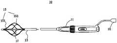
- Fig. 1is a side view of the ablation device provided by the first embodiment of the application
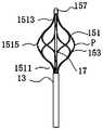
- Fig. 2is an enlarged schematic diagram of a partial area of the ablation device shown in Fig. 1;
- Figure 3is a cross-sectional view of the inner sheath and the outer sheath
- Figure 4is a cross-sectional view of the rod body
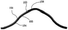
- FIG. 5is an application scenario diagram of an ablation component provided by an embodiment of this application.
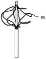
- FIG. 6is a schematic diagram of a possible structure of an ablation component provided by an embodiment of this application.
- FIG. 10is a schematic diagram of a part of the structure of the ablation device provided by the third embodiment of this application.
- FIG. 11is a schematic diagram of a part of the structure of the ablation device provided by the fourth embodiment of this application.
- Figure 12is a schematic cross-sectional view of the distal end of the ablation assembly and the sleeve
- FIG. 13is a schematic diagram of an application scene of the ablation device shown in FIG. 11 for ablating myocardial hypertrophy patients;
- FIG. 14is a flow chart of the method for preparing the ablation device provided by this application.
- Fig. 15is a flowchart of step 101 shown in Fig. 14.
- the rangeis continuous and includes the minimum and maximum values of the range and each value between these minimum and maximum values. Furthermore, in the case where the range refers to an integer, there are only integers including the minimum value to and including the maximum value of this range. In addition, where multiple ranges are provided to describe features or characteristics, such ranges can be combined.
- distal and proximaldefine the position or orientation of the handle (e.g., handle assembly) relative to the clinician or clinician.
- Remotelyor “remotely” refers to a position away from the clinician or clinician's handle or in a direction away from the clinician or clinician.
- Proximalor “proximally” refers to a position close to or in a direction toward the clinician or clinician's handle.
- the direction of the central axis of rotation of objects such as cylinders and tubesis defined as the axial direction
- the direction perpendicular to the axial directionis defined as the radial direction.
- the ablation device 10 provided in the first embodiment of the present applicationis used to ablate a target tissue area with pulse energy to achieve the effect of electrical isolation.
- the target tissue areamay be located in the heart, including but not limited to pulmonary veins, or combined with typical atrial flutter, triggering lesions of non-pulmonary vein origin (such as left atrial appendage, superior vena cava, coronary sinus ostium), etc. It can be understood that the target tissue area is not limited to be located on the heart, and may also be located on other body tissues, which is not limited here.
- the ablation device 10includes a handle 11, an inner sheath 13, an outer sheath 14 (as shown in FIG. 3), and an ablation assembly 15.
- the outer sheath 14is omitted in FIG.
- the outer sheath 14is sleeved on the periphery of the inner sheath 13, and the proximal end of the outer sheath 14 and the proximal end of the inner sheath 13 are both connected with the handle 11.
- the ablation assembly 15includes a plurality of rods 151 provided with electrodes 153. The distal ends of the plurality of rods 151 are joined together. The proximal ends of the plurality of rods 151 are connected to the distal end of the inner sheath 13. Switch between the expanded states.
- the ablation assembly 15In the contracted state, the ablation assembly 15 is movably contained in the outer sheath 14; in the expanded state, the proximal end of the ablation assembly 15 is exposed from the distal end of the outer sheath 14, and each electrode 153 deviates It is located at the position where the helix angle of the rod 151 is the largest.
- the inner sheath 13 and the ablation assembly 15are movably housed in the outer sheath 14.
- the ablation assembly 15is bound by the outer sheath 14.
- the outer diameter of the ablation assembly 15is small, and its maximum outer diameter is the first outer diameter
- both the distal and proximal ends of the ablation assembly 15are exposed (released) from the distal end of the outer sheath 14, and the ablation assembly 15 is approximately lantern-shaped, that is, the ablation assembly 15 includes an axial direction away from it
- the section projecting outward in the direction of the ablation component 15has the largest degree of protruding at the position of the rod 151 with the largest helix angle, and has the largest outer diameter.
- the largest outer diameteris the second outer diameter, and the first outer diameter is smaller than the second outer diameter.
- each electrode 153deviates from the position where the helix angle of the rod 151 is the largest.
- the rod body 151has a first position point P.
- the helix angle of the first position point Pis greater than the helix angles of the other positions of the rod body 151, that is, the helix angle of the rod body 151 at the first position point P is the maximum helix angle of the rod body 151, and the first position point P corresponds to
- the maximum radial dimension on the rod 151has the largest curvature.
- the position other than the first position point P on the rod 151has a small helix angle, a small radial dimension, and a small curvature relative to the first position point P.
- the ablation component 15is in the first position A point P has the largest outer diameter to form the most protruding part in the radial direction.
- Each rod 151extends spirally around the axial direction of the inner sheath 13, and the axial size of the plurality of rods 151 can be changed to adjust the radial dimension at the position of the maximum helix angle on the rod 151, so that the position of the maximum helix angle on the rod 151
- the corresponding outer diameter of the locationalso changes, so that the axial size and the maximum radial size of the ablation component 15 can be changed to match the size of the target ablated tissue area, and the electrode 153 is used to ablate the target ablated tissue.
- the first position point P at the maximum helix anglehas the maximum outer diameter on the rod body 151, so as to make full use of the first position point P or the distance between the first position point P and the rod body 151.
- the arc formed by the endablates the mouth or inside of the vascular tissue, and improves the degree of fit with the target ablated tissue.
- the axial size of the rod 151is changed to adjust the ablation assembly 15 axial size and the outer position at the maximum helix angle.
- the maximum diameter of the ablation component 15(the radial dimension at the maximum position of the helix angle of the rod 151) and the position where the electrode 153 forms the electric field match the target ablated tissue.
- the distance between the proximal end and the distal end of the rod 151increases, the axial size of the rod 151 increases, the axial size of the ablation assembly 15 increases, and the maximum outer diameter of the ablation assembly 15 decreases;
- the distance between the proximal end and the distal enddecreases, the axial size of the rod 151 decreases, the axial size of the ablation assembly 15 decreases, and the maximum outer diameter of the ablation assembly 15 increases.
- Each rod 151spirally extends around the axial direction of the inner sheath 13 so that the ablation assembly 15 forms a spiral distribution structure.
- the adjusted outer diameter of the ablation assembly 15 and the caliber of the vascular tissueare also There is a certain error. There may be a situation where the caliber of the vascular tissue is smaller than the maximum outer diameter of the ablation assembly 15.
- the maximum position of the helix angle of the rod 151is under the restraint of the pulmonary vein, and there is more in the radial direction.
- Part of the rod 151is offset toward the proximal end in the direction of the helix, resulting in an increase in the outer diameter and helix angle of the proximal part of the rod 151. Since the proximal ends of the plurality of rods 151 are connected to the distal end of the inner sheath 13, The outer diameter gradually decreases, so it can slow down the increasing trend of the proximal outer diameter and helix angle of the rod 151.
- the proximal end of the ablation assembly 15When the adjusted outer diameter of the ablation assembly 15 is not much different from the caliber of the vascular tissue, the proximal end of the ablation assembly 15 After the diameter is enlarged, it will not exceed the caliber of the vascular tissue, so that the outer diameter of the ablation assembly 15 (the helix angle is the largest) and the proximal end have less resistance to enter the vascular tissue, which is conducive to the smoothness of the ablation assembly 15 Into the vasculature, that is, the ablation component 15 has better compliance and can better fit the target tissue area, which is beneficial to improve the surgical effect.
- the electrode 153has a certain length (a dimension extending along the length of the rod 151). It is arranged on the spiral rod 151, especially the electrode 153 with a larger hardness and a longer length, which will reduce the compliance of the position where the electrode 153 is arranged on the rod 151.
- the flexibilitythat is, the flexibility of the position where the electrode 153 is set is relatively poor, and a certain resistance will be brought about when the ablation assembly 15 (rod 151) changes its outer diameter.
- the electrode 153in the expanded state, the electrode 153 is located on the rod 151 where the helix angle, outer diameter, and curvature of the rod 151 are the largest, which is beneficial to reduce the ablation assembly 15 and the adjustment of the rod 151.
- the position with the largest helix angleis located at the edge of the ablation component 15, and the deviation of the electrode 153 from the position with the largest helix angle is also beneficial to reduce the resistance when it moves relative to the target tissue, and it is also beneficial to further improve the ablation device 100's abutment and compliance with the target. organization.
- the first position point Pis located at the center of the rod 151.
- the shaft 151includes a proximal section 1511, a distal section 1513, and an intermediate section 1515 located between the proximal section 1511 and the distal section 1513.
- the proximal section 1511includes the most proximal end of the rod body 151.
- the distal section 1513includes the most distal end of the shaft 151.
- the first position point Pis a position starting from the closest end of the rod 151 to one half of the length of the rod 151.
- the helix angle of the proximal end of the rod 151 and the helix angle of the most distal end of the rod 151are smaller than the helix angle of the first position of the rod 151.
- the angle of the helix angle of the rod 151is symmetrically distributed along the rod 151 on both sides of the first position point P.
- the electrode 153is arranged deviating from the first position of the rod 151, that is, the electrode 153 is not arranged at the first position of the rod 151, so that in the expanded state of the ablation assembly 15, the electrode 153 deviates from the position where the rod 151 has the greatest curvature.
- the first position pointis not limited to the rod center of the rod 151, and the helix angle of each section on the rod 151 is controlled to be other positions of the rod 151, such as one-third of the length of the rod 151 and so on.
- the helix angle of the proximal section 1511 and the helix angle of the distal section 1513are smaller than the helix angle of the middle section 1515; the angle of the helix angle of the rod 151 is along the rod. 151 are symmetrically distributed on both sides of the middle section 1515, and further, symmetrically distributed on both sides of the first position point P along the rod body 151.
- the helix angle of the proximal section 1511 and the helix angle of the distal section 1513are not limited, but are smaller than the helix angle of the middle section 1515, that is, the helix angle of each position of the rod body 151 is not limited.
- the maximum outer diameter of the rod 151will be The position is bound by the pulmonary vein, and the extra part of the rod 151 in the radial direction shifts toward the proximal end of the rod 151 in the direction of the spiral, resulting in an increase in the outer diameter of the proximal part of the rod 151, so that the pulmonary vein compresses the rod 151 The far end.
- the proximal outer diameter of the ablation assembly 15is reduced, which can effectively slow down the increasing trend of the proximal outer diameter of the rod 151 without causing the contour of the plurality of rods 151 to significantly exceed the diameter of the pulmonary vein at the proximal end, making the ablation assembly 15 can enter the pulmonary vein smoothly, so as to better conform to the anatomical structure of the target tissue area, and the radial support force is improved, which is conducive to a closer fit with the target tissue area, thereby improving the surgical effect.
- the first position points P of all rods 151are arranged on the same plane perpendicular to the axial direction of the inner sheath 13 at intervals, that is, the first position points P of all rods 151 are formed on the same plane perpendicular to the axial direction of the inner sheath 13
- the geometryis discrete.
- the geometric shapes formed by the first position points P of all the rod bodies 151are symmetrical figures, for example, circular, elliptical, semi-circular or any other geometric non-linear shapes, which are not limited herein.
- the number of rods 151is not limited, for example, the number of rods 151 is 4-10.
- the first position points P of the plurality of rods 151are evenly distributed on the same plane perpendicular to the axial direction of the inner sheath 13; the diameter of the most protruding position of the ablation assembly 15 in the natural state ranges from 6 to 25 mm. It can be understood that the first position points P of the plurality of rods 151 are not limited to be uniformly distributed on the same plane perpendicular to the axial direction of the inner sheath 13; the diameter range of the most protruding position of the ablation assembly 15 in the natural state is not limited.
- the proximal ends of the plurality of rod bodies 151are fixedly housed in the distal end of the inner sheath 13.
- the ablation device 10also includes a connector 16 connected to the handle 11, the connector 16 is electrically connected to the electrode 153, and the connector 16 is used to connect to a pulse signal source and deliver pulse signals to the electrode 153 for the electrode 153 to ablate the target tissue area .
- the ablation device 10further includes a traction guide rod 17, the traction guide rod 17 movably penetrates the inner sheath 13, the inner sheath 13 is a hollow tube, and the proximal end of the traction guide rod 17 is connected to the handle 11.
- the distal end of the traction guide rod 17is combined with the distal ends of a plurality of rod bodies 151.
- Each rod body 151is spirally extended around the traction guide rod 17, and the handle 11 is used to pull the traction guide rod 17 to adjust the axial direction of the ablation assembly 15. Length and outer diameter dimensions.
- the traction guide rod 17extends along the axial direction of the inner sheath tube 13, the axial direction of the ablation assembly 15 is the same as the extension direction of the traction guide rod 17, and the traction guide rod 17 is a steel cable.
- the pulling guide rod 17can be a hollow flexible polyimide (PI) tube, a fluorinated polyethylene (PDFE) tube, a stainless steel tube, or other polymer materials.
- the ablation device 10controls the traction guide rod 17 to pull the rods 151 of the ablation assembly 15 through the handle 11 to adjust the outer diameter of the ablation assembly 15.
- the outer diameter of the large ablation component 15is reduced when the traction guide rod 17 moves from the proximal end to the distal direction relative to the inner sheath 13.
- the outer diameter of the ablation assembly 15is flexibly adjusted by the traction guide rod 17, so that the ablation assembly 15 can adapt to blood vessels of different diameters (such as pulmonary veins) or other body tissues, and can perform the target ablation area under any appropriate outer diameter conditions.
- the ablationis not limited to the case where the ablation component 15 must be ablated under the maximum axial compression, which improves the adaptability to the anatomical morphology of different target ablation regions, facilitates the operation of the ablation device 10, and has a good ablation effect.
- the outer diameter of the ablation assembly 15can be increased by adjusting the electrode 153 to generate an electric field at the pulmonary vein orifice to ablate tissue, or the outer diameter of the ablation assembly 15 can be reduced by adjusting.
- the electrode 153is placed in the pulmonary vein to ablate tissue.
- the rod body 15further includes a main rod 154 and an insulating sleeve 155, and the insulating sleeve 155 is sleeved outside the main rod 154.
- the cross-sectional shape of the main rod 154can be a circle, a semicircle, a round drum, or other shapes, and is not limited herein.
- the main rod 154is made of nickel-titanium wire, so that the main rod 154 has excellent elastic properties and strength, so as to be able to closely adhere to the target tissue. It can be understood that the main rod 154 may be made of other materials, such as stainless steel or polymer materials.
- the electrode 153is fixed on the outer wall of the insulating sleeve 155.
- the material of the insulating sleeve 155is Pebax or heat shrinkable tube (such as FEP heat shrinkable tube) or other insulating polymer materials, which ensures the insulation between the electrode 153 and the main rod 154.
- the insulating sleeve 155may be one layer, two layers or multiple layers.
- the electrode 153is fixed to the outer wall of the insulating sleeve 155 by curing glue.
- the electrode 153is made of platinum-iridium alloy or gold or other platinum alloys, and the shape of the electrode 153 conforms to the shape of the rod 151.
- the number of electrodes 153 of each rod 15may be one, two or more.
- the electrodes 153 on each rod 15have the same polarity and are opposite in polarity to the electrodes 153 on the adjacent rod 15.
- Each electrode 153can be configured with different parameters such as voltage, pulse width, repetition frequency, duty cycle and pulse number, single-phase or dual-phase pulse.
- the electrode 153may map the cardiac electrophysiological signal and/or be used to perform other functions such as cardiac pacing.
- all the electrodes 153are used for ablation, and in another period, all of the electrodes 153 are used for mapping, or some of the electrodes 153 are always used for ablation, and some of the electrodes 153 are always used for mapping.
- each electrode 153can be independently addressed, that is, an electrical pulse signal can be output to any electrode as needed to ablate the target tissue area.
- each rod 151is provided with two electrodes 153 (FIGS. 2 and 4).
- the two electrodes 153are located on both sides of the first position point P and the positions of the two electrodes 153 are asymmetrical, that is, one electrode 153 is located at the first position.
- the other electrode 153is located on the distal side of the first position point P.
- a plurality of electrodes 153 on the distal side of the plurality of rods 151surround a first ring.
- the plurality of electrodes 153 on the proximal side of the plurality of rods 151surround a second circular ring for forming a second electric field.
- the diameter of the first circular ringis smaller than that of the second circular ring.
- the diameter of the first electric fieldis smaller than that of the second electric field.
- FIG. 5is an application scenario diagram of the ablation component of the ablation device provided in an embodiment of this application for ablating the pulmonary vein ostium (not intrapulmonary vein).
- the position of the electrode in the embodiment in FIG. 5is different from that in the previous embodiment.
- the two electrodes on each rod 151are arranged on the distal side corresponding to the first position point P of the rod 151, and the mouth 2011 of the pulmonary vein 201 shown in FIG. 5 is relatively large.
- a circle of electrodes composed of the electrodes 153 on the plurality of rods 151 closer to the distal end of the rod 151is called the far circle electrode 1531
- a circle of electrodes 153 on the plurality of rods 151 closer to the proximal end of the rod 151is composed of one circle.
- the circle electrodeis called the near circle electrode 1533.
- the distance between the far circle electrode 1531 and the mouth 2011cannot be ablated, the near circle electrode 1533 fits the mouth 2011 better, the proximal circle electrode 1533 is controlled for ablation, and the far circle electrode 1531 can be controlled to close Or used for mapping. If the caliber of the mouth 2011 of the pulmonary vein 201 is small, the far circle electrode 1531 is selected for ablation.
- the ablation device 10further includes a wire 158, which is inserted through the inner sheath 13 and the insulating sleeve 155, and the proximal end of the wire 158 is electrically connected to the connector 16.
- the distal end of the wire 158is electrically connected to the electrode 153.
- the wire 158 and the main pole 154are insulated from each other.
- the electrode 153 and the wire 158are connected by welding or other processes.
- the lead 158includes a first lead (not shown), the first lead is connected to an external pulse signal source through the connector 16, and the electrode 153 connected to the first lead uses the electrical energy provided by the pulse signal source to ablate the target tissue; And/or the lead 158 includes a second lead (not shown).
- the electrode 153 connected to the second leadis used to collect electrophysiological signals of the target tissue area to generate an electrocardiogram, etc., and the second lead will collect the electrophysiological signals.
- the signalis transmitted to the external processor through the connector 16, on the one hand, it is beneficial to the positioning of the complex cardiac anatomy, which can improve the efficiency of the operation and reduce the radiation of the surgeon and the patient. On the other hand, it can also monitor the completion of the ablation operation and fully control the ablation. The progress of the operation improves the safety of the operation.
- the ablation device 10 of the present applicationcan be connected to an external radio frequency source or other energy delivery equipment through the connector 16.
- the voltage range of the pulse signal received by the electrode 153is 900V-2400V, including all the values and sub-ranges therebetween; the pulse frequency is 1kHz-500kHz, including all the values and sub-ranges therebetween, and the pulse signal source can be unipolar.
- the pulse high voltage power supplycan also be a bipolar high voltage pulse power supply.
- the waveform of the bipolar high voltage pulse signalis alternating between positive and negative pulses in each cycle.
- the maximum voltage that the wire can withstandis 3000V; the all electrodes 153 Can be divided into one or more positive-negative sets.
- the ablation assembly 15further includes an installation sleeve 157, and the distal end of the traction guide rod 17 is fixed in the installation sleeve 157.
- the distal end of each rod 151is fixed to the mounting sleeve 157 so that the distal ends of the plurality of rods 151 are joined together.
- the distal end of the rod body 151extends from the proximal end of the installation sleeve 157 into the installation sleeve 157.
- the angle of the spiral angle of the rod 151is not limited, and is symmetrically distributed along the rod 151 on both sides of the first position point P; it is not limited that all the rods 151 have the same spiral shape, as shown in FIG. 6.
- the ablation devicefurther includes an elastic support structure 37, which is connected to two adjacent rods.
- the distance between the two adjacent rods 151is used to keep the distance between the two adjacent rods 151 to prevent the electrode 153 from generating arcs or sparks due to the too small distance between the rods 151 during the operation of the ablation device 30, which may cause interference.
- the breakdown damage of the target tissueis a mesh structure, and the elastic support structure 37 is arranged along the circumferential direction of the ablation assembly 15.
- the elastic support structure 37covers the distal end section 1513 of the rod body 151.
- the elastic support structure 37is connected to all the rod bodies 151.
- the elastic support structure 37can change its shape along with the outer diameter of the ablation component 15.
- the elastic support structure 37is made of nickel-titanium wire to have excellent elastic properties and high strength.
- the number of elastic support structures 37is not limited. As shown in FIG. 8, the number of elastic support structures 37 is two. One elastic support structure 37 covers the proximal section 1511, and the other elastic support structure 37 covers In the distal section 1513, the elastic support structure 37 can also cover all the rods 151 of the ablation assembly 15, as shown in FIG. 9. The elastic support structure 37 covers at least one of the proximal section 1511, the distal section 1513 and the middle section 1513 of the rod body 151.
- the elastic support structure 37may also be other supports, such as support bars/rods arranged between adjacent rods 151, and components for isolation between electrodes arranged on the rods 151.
- the elastic support structure 37is provided at at least one of the proximal end of the ablation component 15, the distal end of the ablation component 15, and the middle of the ablation component 15, and the middle of the ablation component 15 is located between the proximal end of the ablation component 15 and the The area between the far ends.
- the ablation device provided by the third embodiment of the present applicationhas substantially the same structure as the ablation device provided by the first embodiment, except that the traction guide rod 57 is provided with a traction channel (not shown) in the axial direction.
- the traction channelis used to pierce the guide wire 301, and the mapping electrode 303 at the distal end of the guide wire 301 can be exposed from the most distal end of the traction guide rod 57 for mapping electrophysiological signals. Since a special traction channel is provided with the mapping electrode 303 for mapping the electrophysiological signal, it is convenient to use and control the ablation device.
- the ablation device provided by the fourth embodiment of the present applicationhas substantially the same structure as the ablation device provided by the first embodiment, except that the distal end of the rod 151 extends from the distal end of the sleeve 157
- the sleeve 157is installed, that is, the distal end of the rod 151 is folded in the proximal direction.
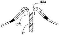
- the mounting sleeve 157includes an inner sleeve 1571 and an outer sleeve 1573, the inner sleeve 1571 is fixedly sleeved on the distal end of the traction guide rod 17, the outer sleeve 1573 is sleeved on the inner sleeve 1571, and the distal end of the rod body 151
- the fixing clampis arranged between the inner sleeve 1571 and the outer sleeve 1573.
- distal end of the rod 151is not limited to be fixed by installing a sleeve 157, and the distal ends of all the rods 151 can also be fixed together in other ways, for example, the distal ends of all the rods 151 are directly glued by curing glue. Together.
- the distal end of the rod body 151extends from the distal end of the installation sleeve 157 into the installation sleeve 157 to form a round turn-up structure 103.
- the turn-up structure 103can effectively reduce the mechanical damage of the ablation component 15 to the target tissue, and better conform to the target tissue.
- FIG. 13is a schematic diagram of an application scenario of the ablation device provided by the fourth embodiment for ablating a patient with myocardial hypertrophy.
- the ablation component 15enters the right atrium 1013 from the inferior vena cava 1011 of the heart along with the distal end of the inner sheath 13, and then enters the left atrial appendage 1015 through the left atrium 1014.
- the traction guide rod 17is controlled by a handle (not shown in FIG. 13), and the outer diameter of the ablation assembly 15 is adjusted to fit the size of the inner cavity of the left atrial appendage 1015.
- the electrode 153is energized to generate an electric field to ablate the left atrial appendage 1015.
- the ablation assembly 15along with the distal end of the inner sheath 13 enters the right atrium 1013 from the inferior vena cava 1011 of the heart, and then enters the left ventricle 1016 through the left atrium 1014.
- the traction guide rod 17is controlled by the handle 11, and the outer diameter of the ablation assembly 15 is adjusted to fit the inner cavity size of the end of the left ventricle 1016 away from the left atrium 1011.
- the electrode 153is energized to generate an electric field to ablate the inner cavity of the end of the left ventricle 1016 away from the left atrium 1011.
- This applicationalso provides a method for preparing the ablation device as described above, which includes the following steps:
- Step 101Provide a plurality of rods shaped into a spiral shape, the distal ends of the plurality of rods are combined together, and each of the rods is provided with an electrode.
- Step 103Connect the proximal ends of the plurality of rods with the distal ends of the inner sheath, each of the rods spirally extending around the axial direction of the inner sheath.
- Step 105Put the inner sheath tube into the outer sheath tube, connect the proximal end of the inner sheath tube and the proximal end of the outer sheath tube to the handle, and the ablation assembly can be in a contracted state and an expanded state.
- the ablation assemblyIn the contracted state, the ablation assembly is movably contained in the outer sheath; in the expanded state, the proximal end of the ablation assembly is exposed from the distal end of the outer sheath, and each Each electrode deviates from the position with the largest helix angle on the rod where it is located.
- step 101which specifically includes the following steps:
- Step 1011cutting the base material to form a plurality of prefabricated rods, a cutting slit is formed between two adjacent prefabricated rods, and the cutting slit extends from the first end of the base material and penetrates the second end of the base material.
- the end face of the endmakes the distal ends of the plurality of main rods joined together.
- the substratesuch as a tube
- the proximal end of the substrateis not cut, that is, the proximal ends of all the prefabricated rods are fixedly connected together; or, the distal end of the substrate is not Cutting, that is, the distal ends of all prefabricated rods are fixedly connected together.
- the prefabricated rodis a straight rod
- the base materialis made of nickel-titanium alloy, stainless steel or polymer materials. It can be understood that the prefabricated rods are not limited to straight rods. It is understandable that a plurality of independent and separate prefabricated rods can be formed by cutting the substrate.
- the prefabricated rodis a piece of nickel-titanium alloy wire, and there is no need to cut the tubular substrate in the axial direction. . Cut the nickel-titanium alloy wire into multiple sections.
- Step 1012heat setting the prefabricated rod material into a spiral shape by a heat setting process to form a main rod, the main rod being helically extended along the axial direction of the inner sheath, and the distal ends of a plurality of the main rods are joined together .
- each prefabricated rodis heat-set by a heat-setting tool.
- Heat setting each prefabricated rod to the required helix angle step by step through the heat setting tool, such as the first setting to 45 degrees, the second setting to 90 degrees..., and the final setting to the required helix angle to prevent one-off Shaping to the required helix anglecauses the prefabricated rod to break and/or twist.
- the prefabricated rod materialis a piece of nickel-titanium alloy wire
- the required rod bodycan be formed in one step by a heat setting tool.
- Step 1013fix and electrically connect the electrode and the wire.
- the electrode and the wireare welded together. It can be understood that the electrode and the wire can also be connected in other ways, for example, a glue connection.
- Step 1014opening a through hole at the position of the pre-installed electrode of the insulating sleeve, the through hole deviating from the position where the rod body has the greatest degree of curvature.
- Step 1015Pass the proximal end of the wire through the through hole and out of the proximal opening of the insulating sleeve.
- Step 1016Fix the electrode on the pre-installed electrode position of the insulating sleeve.
- step 1017the main rod is inserted into the insulating sleeve fixed with the electrode, and the wire is clamped between the inner wall of the insulating sleeve and the main rod and insulated from each other to form the rod body.
- step 101if prefabricated rods are already prepared, step 1011 is omitted.
- the step 103that is, the connecting the proximal ends of the plurality of rods with the distal end of the inner sheath includes: the distal end of the wire penetrates from the distal end of the inner sheath and exits from the proximal end of the inner sheath, and It is electrically connected with the connector on the handle, and the proximal end of the main rod is fixedly connected with the distal end of the inner sheath.
- step 105 and after step 103, or after step 105it further includes the step of: piercing the traction guide rod through the inner sheath and exposing the distal end of the inner sheath, the The distal ends of the plurality of rods are fixed together with the distal ends of the traction guide rods.
- step labelssuch as 101, 1015, etc., are introduced for the sake of simplicity, and the above step labels are not used to limit the sequence of steps.
- the preparation methodfurther includes the step of: arranging an elastic support structure on at least one of the proximal end of the ablation component, the distal end of the ablation component, and the middle of the ablation component, where the middle of the ablation component is located in the ablation component.
- the area between the proximal end of the ablation component and the distal end of the ablation componentis used to keep two adjacent rods at a distance from each other to prevent electrodes from being caused by the small distance between the rods during the operation of the ablation device Produce electric arcs or sparks, causing breakdown damage to the target tissue.
- the elastic support structurecan be arranged on the ablation component by bonding or welding.
- the elastic support structureis a mesh structure made of nickel-titanium wire, and the elastic support structure is arranged along the circumferential direction of the ablation component.
- the elastic support structurecovers the distal end section of the rod body.
- the elastic support structureis connected with all the rod bodies.
- the elastic support structurecan change shape along with the outer diameter of the ablation component.
- the elastic support structuremay also be other supports, such as support bars/rods arranged between adjacent rods, and components for isolation between electrodes arranged on the rods.
Landscapes
- Health & Medical Sciences (AREA)
- Surgery (AREA)
- Engineering & Computer Science (AREA)
- Life Sciences & Earth Sciences (AREA)
- Biomedical Technology (AREA)
- Otolaryngology (AREA)
- Nuclear Medicine, Radiotherapy & Molecular Imaging (AREA)
- Plasma & Fusion (AREA)
- Physics & Mathematics (AREA)
- Heart & Thoracic Surgery (AREA)
- Medical Informatics (AREA)
- Molecular Biology (AREA)
- Animal Behavior & Ethology (AREA)
- General Health & Medical Sciences (AREA)
- Public Health (AREA)
- Veterinary Medicine (AREA)
- Surgical Instruments (AREA)
Abstract
Description
Translated fromChinese本申请要求在2020年4月13日提交中国国家知识产权局、申请号为202010287213.2(申请名称为“消融装置及其制备方法”)、申请号为202020539132.2(申请名称为“消融装置”)的中国专利申请的优先权,其全部内容通过引用结合在本申请中。This application is required to be submitted to the State Intellectual Property Office of China on April 13, 2020, the application number is 202010287213.2 (the application name is "ablation device and its preparation method"), the application number is 202020539132.2 (the application name is "ablation device") China The priority of the patent application, the entire content of which is incorporated in this application by reference.
本申请涉及医疗器械技术领域,特别涉及一种消融装置及其制备方法。This application relates to the technical field of medical devices, and in particular to an ablation device and a preparation method thereof.
心房颤动(Atrial Fibrillation,AF)简称房颤,是最常见的持续性心律失常,随着年龄的增长,房颤发生率不断增加,75岁以上人群可达10%。房颤时心房激动的频率达300~600次/分,心跳频率往往快而且不规则,有时候可达100~160次/分,不仅比正常人心跳快得多,而且绝对不整齐,心房失去有效的收缩功能。AF通常增加了获得许多潜在致命并发症的风险,包括血栓栓塞性中风,扩张性心肌病和充血性心力衰竭,常见的AF症状如心悸,胸痛,呼吸困难,疲劳和头晕也会影响生活质量。与正常人相比,患有房颤的人平均发病率增加了五倍,死亡率增加了两倍。Atrial fibrillation (AF) is abbreviated as atrial fibrillation, which is the most common persistent arrhythmia. With age, the incidence of atrial fibrillation continues to increase, reaching 10% of people over 75 years of age. In atrial fibrillation, the frequency of atrial activation is 300-600 beats/min. The heartbeat frequency is often fast and irregular, sometimes up to 100-160 beats/min. Not only is the heartbeat much faster than normal people, but it is absolutely irregular and the atria is lost. Effective contraction function. AF usually increases the risk of many potentially fatal complications, including thromboembolic stroke, dilated cardiomyopathy, and congestive heart failure. Common AF symptoms such as palpitations, chest pain, dyspnea, fatigue and dizziness can also affect the quality of life. Compared with normal people, the average morbidity of people with atrial fibrillation has increased by five times, and the mortality rate has increased by two times.
组织消融通常用于治疗各种心律失常,其中包括心房颤动。为了治疗心律失常,可以进行消融以改变组织,例如阻止异常电传播和/或破坏通过心脏组织的异常电传导。消融治疗包括多方面:一方面是依靠时间依赖性传导的加热或冷却,以消融组织,如射频消融、激光消融、微波消融、热物质消融等,另一些研究也出现了可供选择的新能源来消融组织,如利用生物电穿孔原理的消融。Tissue ablation is commonly used to treat various arrhythmias, including atrial fibrillation. To treat arrhythmias, ablation can be performed to modify the tissue, for example to prevent abnormal electrical transmission and/or disrupt abnormal electrical conduction through heart tissue. Ablation therapy includes many aspects: On the one hand, it relies on time-dependent conduction of heating or cooling to ablate tissues, such as radiofrequency ablation, laser ablation, microwave ablation, thermal material ablation, etc., and other studies have also shown alternative new energy sources. To ablate tissue, such as ablation using the principle of bioelectroporation.
每个人的人体血管的直径都不同,而且由于不同的要消融的位置,人体内的血管直径也不同。大多数人体血管的直径广泛地范围在约2到约12mm。在常规技术中,消融装置的支架扩展尺寸通常是恒定的,不能根据人体内血管的不同的直径来调适,使得消融组件的顺应性与贴壁性不高,影响手术效果。The diameter of human blood vessels is different for each person, and because of different locations to be ablated, the diameter of blood vessels in the human body is also different. The diameter of most human blood vessels widely ranges from about 2 to about 12 mm. In the conventional technology, the expansion size of the stent of the ablation device is usually constant and cannot be adjusted according to the different diameters of blood vessels in the human body, so that the compliance and adherence of the ablation component are not high, which affects the surgical effect.
发明内容Summary of the invention
为了解决前述问题,本申请提供一种能够提高顺应性与贴壁性的消融装置,以确保消融手术效果。In order to solve the aforementioned problems, the present application provides an ablation device that can improve compliance and adherence to ensure the effect of ablation surgery.
第一方面,本申请提供一种消融装置,包括手柄、内鞘管、外鞘管及消融组件,所述内鞘管的近端以及所述外鞘管的近端均与所述手柄连接,所述外鞘管套设于所述内鞘管的外围,所述消融组件包括多个设置有电极的杆体,所述多个杆体的远端结合在一起,所述多个杆体的近端连接于所述内鞘管的远端,每个杆体绕所述内鞘管的轴向螺旋延伸设置,所述消融组件能够在收缩状态与扩张状态之间切换,在所述收缩状态下,所述消融组件活动收容于所述外鞘管内;在所述扩张状态下,所述消融组件的近端从所述外鞘管的远端露出,并且每个电极偏离其所在杆体上螺旋角最大的位置。In a first aspect, the present application provides an ablation device, including a handle, an inner sheath, an outer sheath, and an ablation assembly, the proximal end of the inner sheath and the proximal end of the outer sheath are both connected to the handle, The outer sheath tube is sleeved on the periphery of the inner sheath tube, the ablation assembly includes a plurality of rods provided with electrodes, the distal ends of the plurality of rods are joined together, and the proximal ends of the plurality of rods are connected At the distal end of the inner sheath, each rod extends spirally around the axial direction of the inner sheath, and the ablation assembly can be switched between a contracted state and an expanded state. In the contracted state, the The ablation assembly is movably contained in the outer sheath; in the expanded state, the proximal end of the ablation assembly is exposed from the distal end of the outer sheath, and each electrode deviates from the position where the helix angle is the largest on the rod. .
第二方面,本申请提供一种消融装置的制备方法,包括以下步骤:提供多个被定型成螺旋状的杆体,所述多个杆体的远端结合在一起,每个杆体上设置有电极;In a second aspect, the present application provides a method for preparing an ablation device, including the following steps: providing a plurality of rods shaped into a spiral shape, the distal ends of the plurality of rods are joined together, and each rod is provided with an electrode;
将多个杆体的近端与内鞘管的远端连接,每个杆体绕所述内鞘管的轴向螺旋延伸设置;以及Connecting the proximal ends of the plurality of rods with the distal end of the inner sheath, each rod extending spirally around the axial direction of the inner sheath; and
将所述内鞘管穿置于外鞘管内,将所述内鞘管的近端以及所述外鞘管的近端与手柄连接,所述消融组件能够在收缩状态与扩张状态之间切换,在所述收缩状态下,所述消融组件活动收容于所述外鞘管内;在所述扩张状态下,所述消融组件的近端从所述外鞘管的远端露出,并且每个电极偏离其所在杆体上螺旋角最大的位置。Put the inner sheath tube into the outer sheath tube, connect the proximal end of the inner sheath tube and the proximal end of the outer sheath tube to a handle, and the ablation assembly can be switched between a contracted state and an expanded state, In the contracted state, the ablation assembly is movably contained in the outer sheath; in the expanded state, the proximal end of the ablation assembly is exposed from the distal end of the outer sheath, and each electrode deviates The position where the helix angle is the largest on the rod.
本申请提供的消融装置及其制备方法,每个杆体绕内鞘管的轴向螺旋延伸设置,使消融组件形成螺旋分布结构,在扩张状态下,杆体上螺旋角最大的位置对应的径向尺寸相对于杆体上的其他位置的径向尺寸更大,即杆体上螺旋角最大位置处的径向尺寸最大,在径向向外突出程度最大,在杆体上的弯曲程度最大。In the ablation device and the preparation method thereof provided in the present application, each rod is arranged to spirally extend around the axial direction of the inner sheath, so that the ablation component forms a spiral distribution structure. In the expanded state, the position on the rod with the largest helix angle corresponds to the radial dimension Compared with other positions on the rod body, the radial dimension is larger, that is, the radial dimension at the position of the maximum helix angle on the rod body is the largest, the radially outward protrusion degree is the greatest, and the rod body has the greatest degree of bending.
在进入脉管组织中时,比如肺静脉,消融组件的外径与脉管组织的口径还存在一定误差,可能存在的一种情况是脉管组织的口径比消融组件的最大外径小,则在进入过程中,杆体螺旋角最大位置在肺静脉的束缚下,其径向上多出的部分杆体沿螺旋线方向朝近端偏移,导致杆体的近端部分的外径以及螺旋角有增大的趋势。由于多个杆体的近端连接于内鞘管的远端,外径以及螺旋角逐渐减小,因此能够减缓杆体近端外径与螺旋角的增大趋势,在消融组件的外径与脉管组织口径相差不大的情况下,消融组件近端外径扩大后也不会超过脉管组织的口径,从而使消融组件的螺旋角最大处,以及其近端进入脉管组织的阻力较小,有利于消融组件平滑顺利的进入脉管系统中,即消融组件具更好的顺应性,能够更好地紧密贴靠目标组织区域,有利于提高消融手术效果。When entering vascular tissue, such as the pulmonary vein, there is still a certain error between the outer diameter of the ablation component and the caliber of the vascular tissue. There may be a situation where the caliber of the vascular tissue is smaller than the maximum outer diameter of the ablation component. During the entry process, the maximum position of the helix angle of the rod is bound by the pulmonary vein, and the extra part of the rod in the radial direction shifts toward the proximal end along the helix direction, resulting in an increase in the outer diameter and helix angle of the proximal part of the rod. . Since the proximal ends of the multiple rods are connected to the distal end of the inner sheath, the outer diameter and helix angle are gradually reduced, which can slow down the increasing trend of the proximal outer diameter and helix angle of the rod. When the tissue calibers are not much different, the outer diameter of the proximal end of the ablation component will not exceed the caliber of the vascular tissue after the expansion, so that the helix angle of the ablation component and the proximal end have less resistance to enter the vascular tissue. It is beneficial for the ablation component to enter the vasculature smoothly, that is, the ablation component has better compliance, can better fit the target tissue area, and is beneficial to improve the effect of ablation surgery.
另外,在扩张状态下,电极位于杆体上偏离杆体上螺旋角最大的位置,即偏离消融组件上径向最突出并且弯曲度最大的位置,有利于减小消融组件以及杆体调节外径时的阻力,有利于进一步提高消融装置的贴靠性并顺应目标组织。螺旋角最大的位置位于消融组件的边缘,电极偏离螺旋角最大的位置还有利于减小其相对目标组织运动时的阻力,亦有利于进一步提高消融装置的贴靠性并顺应目标组织。In addition, in the expanded state, the electrode is located on the rod body at the position where the helix angle on the rod body is the largest, that is, it deviates from the position on the ablation assembly that is the most protruding in the radial direction and has the greatest curvature, which is beneficial to reduce the resistance of the ablation assembly and the rod body when adjusting the outer diameter. , Which is beneficial to further improve the ablation device's closeness and conform to the target tissue. The position with the largest helix angle is located at the edge of the ablation component, and the deviation of the electrode from the position with the largest helix angle is also beneficial to reduce its resistance when moving relative to the target tissue, and is also beneficial to further improve the ablation device's abutment and conform to the target tissue.
为了更清楚地说明本申请实施方式或现有技术中的技术方案,下面将对实施方式或现有技术描述中所需要使用的附图作简单地介绍,显而易见地,下面描述中的附图仅仅是本申请的一些实施方式,对于本领域普通技术人员来讲,在不付出创造性劳动的前提下,还可以根据这些附图获得其他的附图。In order to more clearly illustrate the technical solutions in the embodiments of the present application or the prior art, the following will briefly introduce the drawings that need to be used in the description of the embodiments or the prior art. Obviously, the drawings in the following description are only These are some implementations of the present application. For those of ordinary skill in the art, other drawings can be obtained based on these drawings without creative work.
图1为本申请第一实施方式提供的消融装置的侧视图;Fig. 1 is a side view of the ablation device provided by the first embodiment of the application;
图2为图1所示的消融装置的部分区域放大示意图;Fig. 2 is an enlarged schematic diagram of a partial area of the ablation device shown in Fig. 1;
图3为内鞘管与外鞘管的剖视图;Figure 3 is a cross-sectional view of the inner sheath and the outer sheath;
图4为杆体的剖视图;Figure 4 is a cross-sectional view of the rod body;
图5为本申请一实施方式提供的消融组件的应用场景图;FIG. 5 is an application scenario diagram of an ablation component provided by an embodiment of this application;
图6为本申请一实施方式提供的消融组件的一可能结构示意图;FIG. 6 is a schematic diagram of a possible structure of an ablation component provided by an embodiment of this application;
图7-图9为本申请第二实施方式提供的消融装置的可能结构示意图;7-9 are schematic diagrams of possible structures of the ablation device provided by the second embodiment of this application;
图10为本申请第三实施方式提供的消融装置的部分结构示意图;10 is a schematic diagram of a part of the structure of the ablation device provided by the third embodiment of this application;
图11为本申请第四实施方式提供的消融装置的部分结构示意图;FIG. 11 is a schematic diagram of a part of the structure of the ablation device provided by the fourth embodiment of this application;
图12为消融组件的远端与装设套筒的剖面示意图;Figure 12 is a schematic cross-sectional view of the distal end of the ablation assembly and the sleeve;
图13为图11所示的消融装置对心肌肥厚型患者进行消融的应用场景示意图;FIG. 13 is a schematic diagram of an application scene of the ablation device shown in FIG. 11 for ablating myocardial hypertrophy patients;
图14为本申请提供的消融装置的制备方法流程图;FIG. 14 is a flow chart of the method for preparing the ablation device provided by this application;
图15为图14所示的步骤101的流程图。Fig. 15 is a flowchart of
下面将结合本申请实施方式中的附图,对本申请实施方式中的技术方案进行清楚、完整地描述,显然,所描述的实施方式仅仅是本申请一部分实施方式,而不是全部的实施方式。基于本申请中的实施方式,本领域普通技术人员在没有作出创造性劳动前提下所获得的所有其他实施方式,都属于本申请保护的范围。The technical solutions in the embodiments of the present application will be described clearly and completely in conjunction with the accompanying drawings in the embodiments of the present application. Obviously, the described embodiments are only a part of the embodiments of the present application, rather than all of them. Based on the implementation manners in this application, all other implementation manners obtained by those of ordinary skill in the art without creative work shall fall within the protection scope of this application.
在以下描述中,出于解释的目的,阐述了许多具体细节,以便提供对本申请的透彻理解。然而,对于本领域技术人员显而易见的是,本申请可以在没有这些具体细节或具有等同布置的情况下实施。In the following description, for the purpose of explanation, many specific details are set forth in order to provide a thorough understanding of the present application. However, it is obvious to those skilled in the art that this application can be implemented without these specific details or with equivalent arrangements.
在本申请中公开数值范围的情况下,除非另有说明,否则该范围是连续的,包括该范围的最小值和最大值以及这些最小值和最大值之间的每个值。再此外,在范围指整数的情况下,只有包括从最小值到和包括这个范围的最大值的整数。此外,在提供多个范围来描述特征或特征的情况下,这样的范围能够组合。In the case where a numerical range is disclosed in this application, unless otherwise specified, the range is continuous and includes the minimum and maximum values of the range and each value between these minimum and maximum values. Furthermore, in the case where the range refers to an integer, there are only integers including the minimum value to and including the maximum value of this range. In addition, where multiple ranges are provided to describe features or characteristics, such ranges can be combined.
文本中的“和/或”仅仅是一种描述关联对象的关联关系,表示可以存在三种关系,例如,A和/或B,可以表示:单独存在A,同时存在A和B,单独存在B这三种情况。另外,在本申请实施例的描述中,“多个”是指两个或多于两个。The "and/or" in the text is only an association relationship describing the associated objects, indicating that there can be three relationships, for example, A and/or B, which can mean: A alone exists, A and B exist at the same time, and B exists alone These three situations. In addition, in the description of the embodiments of the present application, "plurality" refers to two or more than two.
如本申请中所使用的,术语“远端”和“近端”限定了相对于临床医生或临床医生的手柄(例如把手组件)的位置或方向。“远端”或“远端地”是指远离临床医生或临床医生的手柄的位置或在离开临床医生或临床医生的方向上的位置。“近端”或“近端地”是指接近临床医生或临床医生的手柄的位置或在朝向临床医生或临床医生的手柄的方向上的位置。As used in this application, the terms "distal" and "proximal" define the position or orientation of the handle (e.g., handle assembly) relative to the clinician or clinician. "Remotely" or "remotely" refers to a position away from the clinician or clinician's handle or in a direction away from the clinician or clinician. "Proximal" or "proximally" refers to a position close to or in a direction toward the clinician or clinician's handle.
另外,将柱体、管体等一类物体的旋转中心轴的方向定义为轴向,与轴向垂直的方向定义为径向。该等定义,只是为了表述方便,并不构成对本申请的限制。In addition, the direction of the central axis of rotation of objects such as cylinders and tubes is defined as the axial direction, and the direction perpendicular to the axial direction is defined as the radial direction. These definitions are only for the convenience of presentation and do not constitute a restriction on this application.
请参阅图1至图3,本申请第一实施方式提供的消融装置10,用于通过脉冲能量对目标组织区域进行消融,达到电隔离的效果。所述目标组织区域可以位于心脏,包括但不限于肺静脉,或者合并有典型心房扑动、非肺静脉起源的触发灶(如左心耳,上腔静脉、冠脉静脉窦口)等。可以理解,所述目标组织区域不限定位于心脏,也可以位于其他机体组织上,在此不作限定。1 to 3, the
消融装置10包括手柄11、内鞘管13、外鞘管14(如图3所示)及消融组件15,为方便说明,图1中省略了外鞘管14。外鞘管14套设于内鞘管13的外围,外鞘管14的近端以及内鞘管13的近端均与手柄11连接。消融组件15包括多个设置有电极153的杆体 151,多个杆体151的远端结合在一起,多个杆体151的近端连接于内鞘管13的远端,消融组件15能够在收缩状态与扩张状态之间切换,在收缩状态下,消融组件15活动收容于外鞘管14内;在扩张状态下,消融组件15的近端从外鞘管14的远端露出,并且每个电极153偏离其所在杆体151上螺旋角最大的位置。The
在收缩状态下,内鞘管13与消融组件15活动收容于外鞘管14内,消融组件15被外鞘管14束缚,消融组件15的外径较小,其最大外径为第一外径;在扩张状态下,消融组件15的远端与近端均从外鞘管14的远端露出(释放出来),消融组件15外形轮廓大概呈灯笼状,即消融组件15包括沿背离轴向的方向向外突出的区段,消融组件15中杆体151上螺旋角最大的位置处向外突出程度最大,具有最大外径,该最大外径为第二外径,第一外径小于第二外径,在扩张状态下,每个电极153偏离其所在杆体151的螺旋角最大的位置。In the contracted state, the
具体的,杆体151具第一位置点P。在扩张状态下,第一位置点P的螺旋角大于杆体151其他位置的螺旋角,即杆体151于第一位置点P的螺旋角为杆体151的最大螺旋角,并且第一位置点P处对应杆体151上的最大径向尺寸,弯曲度最大,杆体151上第一位置点P以外的位置相对于第一位置点P,螺旋角小、径向尺寸小、弯曲度小,消融组件15在第一位置点P具最大外径以在径向形成最突出的部分。Specifically, the
每个杆体151绕内鞘管13的轴向螺旋延伸设置,多个杆体151的轴向尺寸能够变化,以调节杆体151上螺旋角最大位置处的径向尺寸,从而杆体151上螺旋角最大位置处对应的外径也随之变化,从而消融组件15的轴向尺寸以及最大径向尺寸能够变化,从而匹配目标消融组织区域的尺寸,电极153用于对目标消融组织进行消融。杆体151轴向尺寸变化的过程中,保证螺旋角最大位置处的第一位置点P具有杆体151上的最大外径,从而充分利用第一位置点P或第一位置点P与杆体151的远端形成的弧度对脉管组织的口部或内部进行消融,提高与目标消融组织的贴合度。Each
在扩张状态下,进行消融作用之前,通过调节杆体151的近端与远端之间的距离,改变杆体151的轴向尺寸,以调节消融组件15的轴向尺寸与螺旋角最大位置处的外径,使得消融组件15的最大外径(杆体151螺旋角最大位置处的径向尺寸)以及电极153形成电场的位置与目标消融组织相匹配。具体地,杆体151的近端与远端之间的距离增大,杆体151的轴向尺寸增大,消融组件15的轴向尺寸增大,消融组件15的最大外径减小;杆体151的近端与远端之间的距离减小,杆体151的轴向尺寸减小,消融组件15的轴向尺寸减小,消融组件15的最大外径增大。In the expanded state, before performing ablation, by adjusting the distance between the proximal end and the distal end of the
每个杆体151绕内鞘管13的轴向螺旋延伸设置使消融组件15形成螺旋分布结构,在进入脉管组织中时,比如肺静脉,消融组件15调节后的外径与脉管组织的口径还存在一定误差,可能存在的一种情况是脉管组织的口径比消融组件15的最大外径小,则在进入过程中,杆体151螺旋角最大位置在肺静脉的束缚下,其径向上多出的部分杆体151沿螺旋线方向朝近端偏移,导致杆体151的近端部分的外径以及螺旋角有增大的趋势,由于多个杆体151的近端连接于内鞘管13的远端,外径逐渐减小,因此能够减缓杆体151近端外径与螺旋角的增大趋势,在消融组件15调节后的外径与脉管组织口径相差不大的情况下,消融组件15近端外径扩大后也不会超过脉管组织的口径,从而使消融组件15的外径 最大(螺旋角最大)处,以及其近端进入脉管组织的阻力较小,有利于消融组件15平滑顺利的进入脉管系统中,即消融组件15具更好的顺应性,能够更好地紧密贴靠目标组织区域,有利于提高手术效果。Each
电极153是具有一定长度(沿着杆体151长度方向延伸的尺寸)的,设置在螺旋状的杆体151上,特别是硬度较大长度较长的电极153,会降低杆体151设置电极153位置的柔顺性,即设置电极153位置的柔顺性相对较差,在消融组件15(杆体151)变化外径的过程中,会带来一定的阻力。本申请中提供的消融装置10,在扩张状态下,电极153位于杆体151上偏离杆体151上螺旋角最大、外径最大以及弯曲度最大的位置,有利于减小消融组件15以及杆体151调节外径时的阻力。螺旋角最大的位置位于消融组件15的边缘,则电极153偏离螺旋角最大的位置还有利于减小其相对目标组织运动时的阻力,亦有利于进一步提高消融装置100的贴靠性并顺应目标组织。The
本实施方式中,第一位置点P位于杆体151的杆体中心。杆体151包括近端段1511、远端段1513,以及位于近端段1511与远端段1513之间的中间段1515。近端段1511包括杆体151的最近端。远端段1513包括杆体151的最远端。所述第一位置点P为,以杆体151的最近端为始至杆体151的长度的二分之一所在位置。所述扩张状态下,杆体151的最近端的螺旋角与杆体151的最远端的螺旋角,要小于杆体151的第一位置点的螺旋角。所述扩张状态下,杆体151的螺旋角的角度,沿杆体151在第一位置点P的两侧呈对称分布。电极153偏离杆体151的第一位置点处设置,即电极153不设置于杆体151的第一位置点,使消融组件15在所述扩张状态下,电极153偏离杆体151的弯曲度最大的位置。In this embodiment, the first position point P is located at the center of the
可以理解,不限定第一位置点为杆体151的杆体中心,通过控制杆体151上各个区段的螺旋角使其为杆体151的其他位置,例如杆体151的三分之一长度处等等。It can be understood that the first position point is not limited to the rod center of the
可以理解,在本实施方式中,所述扩张状态下,近端段1511的螺旋角与远端段1513的螺旋角,要小于中间段1515的螺旋角;杆体151的螺旋角的角度,沿杆体151在中间段1515两侧呈对称分布,进一步地,沿杆体151在第一位置点P两侧呈对称分布。It can be understood that in this embodiment, in the expanded state, the helix angle of the
可以理解,不限定近端段1511的螺旋角与远端段1513的螺旋角,要小于中间段1515的螺旋角,即对杆体151各个位置点的螺旋角不作限定。It can be understood that the helix angle of the
以消融组件15深入肺静脉的过程为例,若肺静脉直径相对杆体151的螺旋角最大位置(最大外径位置)处形成的外部轮廓较小,消融组件15在进入过程中,杆体151的最大外径位置在肺静脉的束缚下,其径向上多出的部分杆体151沿螺旋线方向朝杆体151的近端偏移,导致杆体151的近端部分的外径有增大的趋势,使得肺静脉压迫杆体151的远端。由于消融组件15在径向盘旋,从而肺静脉的压迫使杆体151近端的螺旋角变大,即在周向上的扭曲角度变大,结合多个杆体151的近端与内鞘管13的远端连接,消融组件15的近端外径减小,能够有效减缓杆体151的近端外径增大趋势,而不会导致多个杆体151的轮廓在近端直径明显超出肺静脉的直径,使得消融组件15能够平滑顺利进入肺静脉,从而更好的顺应目标组织区域的解剖结构,并且径向支撑力有所提高,有利于与目标组织区域贴合更紧密,从而提高手术效果。Taking the process of the
所有杆体151的第一位置点P间隔排布于垂直内鞘管13轴向的同一平面上,即所有杆体151的第一位置点P在垂直于内鞘管13轴向的同一平面上的组成的几何形状是离散 的。所有杆体151的第一位置点P组成的几何形状为对称图形,例如,圆形,椭圆形,半圆形或任何其他几何形状的非线性形状,在此不作限定。对杆体151的数量不作限定,例如,杆体151的数量为4-10个。本实施方式中,多个杆体151的第一位置点P在垂直于内鞘管13轴向的同一平面均匀分布;消融组件15在自然状态下的最突出位置的直径范围6~25mm。可以理解,不限定多个杆体151的第一位置点P在垂直于内鞘管13轴向的同一平面均匀分布;消融组件15在自然状态下的最突出位置的直径范围不作限定。The first position points P of all
本实施方式中,多个杆体151的近端固定收容于内鞘管13的远端。In this embodiment, the proximal ends of the plurality of
同个杆体151的最近端与杆体151的最远端在沿内鞘管13的周向上扭转角度为30~70度。在其他实施方式中,扭转角度可以在0~540度范围内选取。消融装置10还包括与手柄11连接的连接器16,连接器16与电极153电连接,连接器16用于与脉冲信号源连接,向电极153输送脉冲信号,供电极153对目标组织区域进行消融。The closest end of the
消融装置10还包括牵引导杆17,牵引导杆17活动穿设于内鞘管13,内鞘管13为空心管,牵引导杆17的近端与手柄11连接。牵引导杆17的远端与多个杆体151的远端结合在一起,每个杆体151绕牵引导杆17螺旋延伸设置,手柄11用于牵拉牵引导杆17实现调节消融组件15的轴向长度以及外径尺寸。本实施方式中,牵引导杆17沿内鞘管13的轴向延伸,消融组件15的轴线方向与牵引导杆17的延伸方向相同,牵引导杆17为钢缆。牵拉导杆17可以为中空的柔性聚酰亚胺(Polyimide,简称PI)管,氟代聚乙烯(PDFE)管,不锈钢管,或者其他高分子材料。The
消融装置10通过手柄11控制牵引导杆17牵拉消融组件15的多个杆体151而调整消融组件15的外径,牵引导杆17由远端向近端方向相对内鞘管13运动时则增大消融组件15的外径,牵引导杆17由近端向远端方向相对内鞘管13运动时则减小消融组件15的外径。通过牵引导杆17灵活调节消融组件15的外径,使消融组件15能够适应不同直径大小的血管(例如肺静脉)或其他机体组织,并能够在任意适当外径尺寸的条件下对目标消融区域进行消融,而非限定在消融组件15必须在轴向压缩程度最大的情形下进行消融,提高了对不同目标消融区域解剖形态的适应性,方便了消融装置10的操作,消融效果好。例如,消融装置10在工作时,通过调节增大消融组件15的外径既可以使得电极153在肺静脉口部通过传递脉冲能量产生电场来消融组织,也可以通过调节减小消融组件15的外径使得电极153放置在肺静脉内进行消融组织。The
请参阅图4,杆体15还包括主杆154与绝缘套管155,绝缘套管155套设于主杆154外。主杆154的截面形状可以为圆形、半圆形、圆鼓或者其他形状,在此不作限定。本实施方式中,主杆154由镍钛丝制成,使得主杆154具有优良的弹性性能及强度,以能够很好地与目标组织贴靠。可以理解,主杆154可以由其他材料制成,例如不锈钢、或高分子材料。电极153固定设于绝缘套管155的外壁。本实施方式中,绝缘套管155的材料为Pebax或者热缩管(比如FEP热缩管)或者其它绝缘高分子材料,保证了电极153与主杆154之间的绝缘性。绝缘套管155可以为一层、两层或多层。Please refer to FIG. 4, the
电极153通过固化胶固定在绝缘套管155的外壁。电极153的制成材料包括铂铱合金或黄金或者其他铂合金,电极153的形状符合杆体151的外形。每个杆体15的电极153的数量可以为一个、两个或多个。每个杆体15上的电极153为同一极性,并与相邻的杆 体15上的电极153极性相反。各个电极153可以配置不同的电压、脉冲宽度、重复频率、占空比和脉冲个数等参数单相或双相脉冲。电极153可以标测心脏电生理信号,和/或用于执行例如心脏起搏的其他功能。比如在一个时段中,全部电极153用于消融,另一时段中,全部用于标测,或者部分电极153始终用于消融,部分电极153始终用于标测。The
本申请中,能够对每个电极153进行独立寻址控制,即根据需要向任意一电极输出电脉冲信号以对目标组织区域进行消融。In this application, each
在本实施方式中,每个杆体151设置有两个电极153(图2与图4),两个电极153位于第一位置点P的两侧并且设置位置不对称,即一个电极153位于第一位置点P的近端侧,另一个电极153位于第一位置点P的远端侧,在扩张状态下,多个杆体151中的多个位于远端侧的电极153围成第一圆环,用于形成第一电场,多个杆体151中的多个位于近端侧的电极153围成第二圆环,用于形成第二电场,第一圆环的直径小于第二圆环,相应地,第一电场的直径小于第二电场。在一种控制方式中,可以根据目标组织区域的大小,选择控制第一圆环上的电极153进行消融,或者选择控制第二圆环上的电极153单独进行消融,或者选择控制第一圆环与第二圆环上的电极153共同进行消融。In this embodiment, each
请参阅图5,为本申请一实施方式中提供的消融装置的消融组件消融肺静脉口部(非肺静脉内)的应用场景图,图5中的实施方式中的电极位置与前面实施方式中的不同,每个杆体151上的两个电极均设于对应杆体151的第一位置点P的远端侧,图5中所示的肺静脉201的口部2011较大。将多个杆体151上更为靠近杆体151的远端的电极153组成的一圈电极称为远圈电极1531,将多个杆体151上更为靠近杆体151的近端的电极153所组成的一圈电极称为近圈电极1533。远圈电极1531与口部2011距离较远无法对口部进行消融,近圈电极1533贴合口部2011较好,控制所述近圈电极1533用于消融,所述远圈电极1531可以被控制关闭或用于标测。若肺静脉201的口部2011的口径较小,则选择使用远圈电极1531进行消融。Please refer to FIG. 5, which is an application scenario diagram of the ablation component of the ablation device provided in an embodiment of this application for ablating the pulmonary vein ostium (not intrapulmonary vein). The position of the electrode in the embodiment in FIG. 5 is different from that in the previous embodiment. The two electrodes on each
在肺静脉内部消融的应用场景中,两圈电极可以根据需要选择性使用。请一并参阅图1、图2与图4,消融装置10还包括导线158,导线158穿设于内鞘管13内部及绝缘套管155内部,导线158的近端与连接器16电连接,导线158的远端与电极153电连接。导线158与主杆154彼此绝缘。电极153与导线158之间通过焊接或者其他工艺连接。In the application scenario of internal pulmonary vein ablation, two circles of electrodes can be selectively used as needed. Please refer to FIGS. 1, 2 and 4 together. The
导线158包括第一导线(图未示),第一导线通过连接器16连接至外部的脉冲信号源,与第一导线连接的电极153利用所述脉冲信号源提供的电能对目标组织进行消融;和/或导线158包括第二导线(图未示),与第二导线连接的电极153用于采集目标组织区域的电生理信号以生成心电描记图等,第二导线将采集到的电生理信号通过连接器16传输至外部处理器,一方面有利于复杂心脏解剖结构的定位,可提高手术效率,减少术者和患者的辐射,另一方面也可以监测消融手术的完成情况,充分掌控消融的进度,提高手术的安全性。The
可以理解,本申请消融装置10可通过连接器16连接至外部的射频发生源,或其他能量输送设备。It can be understood that the
本实施方式中,电极153接收到的脉冲信号的电压范围为900V~2400V,包括其间的所有值和子范围;脉冲频率为1kHz~500kHz,包括其间的所有值和子范围,脉冲信号 源可以为单极性脉冲高压电源,也可以为双极性高压脉冲电源,双极性高压脉冲信号波形在每个周期内,正负极性脉冲交替,相应地,导线承受的最大电压3000V;所述全部电极153可被分为一个或者多个正极-负极集合。In this embodiment, the voltage range of the pulse signal received by the
请再次参阅图2,消融组件15还包括装设套筒157,牵引导杆17的远端固定于装设套筒157内。每个杆体151的远端固定在装设套筒157,使得多个杆体151的远端结合在一起。本实施方式中,杆体151的远端从装设套筒157的近端伸入装设套筒157。通过装设套筒157使多个杆体151的远端结合在一起,有利于提高杆体151的远端连接强度。装设套筒157的远端为倒圆结构,有利于减小对目标组织造成的器械损伤,亦能让消融组件15很好地顺应目标组织区域(比如左心耳)。Please refer to FIG. 2 again. The
可以理解,不限定杆体151的螺旋角的角度,沿杆体151在第一位置点P的两侧呈对称分布;不限定所有杆体151的螺旋形态相同,如图6所示。It can be understood that the angle of the spiral angle of the
请参阅图7,本申请第二实施方式提供的消融装置与第一实施方式提供的消融装置10的不同在于,消融装置还包括弹性支撑结构37,弹性支撑结构37连接于相邻的两个杆体151之间,用于使两个相邻的杆体151相互之间保持间距,防止在消融装置30在工作过程中,因为杆体151之间间距过小导致电极153产出电弧或者电火花,造成对目标组织的击穿伤害。本实施方式中,弹性支撑结构37为网状结构,弹性支撑结构37沿消融组件15的周向设置。弹性支撑结构37包覆杆体151的远端段1513。弹性支撑结构37与所有的杆体151连接。弹性支撑结构37能够随同消融组件15的外径而变化形状。本实施方式中,弹性支撑结构37由镍钛丝制成,以具有优良的弹性性能及较高强度。Referring to FIG. 7, the difference between the ablation device provided in the second embodiment of the present application and the
可以理解,对弹性支撑结构37的数量不作限定,如图8所示,弹性支撑结构37的数量为两个,一个弹性支撑结构37包覆在近端段1511,另一个弹性支撑结构37包覆在远端段1513,弹性支撑结构37还可以包覆消融组件15的所有杆体151,如图9所示。弹性支撑结构37至少包覆杆体151的近端段1511、远端段1513与中间段1513中的至少一个。It can be understood that the number of
可以理解,该弹性支撑结构37还可以是其他支撑件,比如设置在相邻杆体151之间的支撑条/杆,以及杆体151上设置的用于电极之间隔离的部件。It can be understood that the
可以理解,弹性支撑结构37设置在消融组件15的近端、消融组件15的远端、消融组件15的中部中的至少一个,消融组件15的中部位于消融组件15的近端与消融组件15的远端之间区域。It can be understood that the
请参阅图10,本申请第三实施方式提供的消融装置与第一实施方式提供的消融装置结构大致相同,不同在于,牵引导杆57沿轴向设有牵引通道(图未示),所述牵引通道用于穿设导丝301,导丝301远端的标测电极303能够从所述牵引导杆57的最远端露出,以进行标测电生理信号。由于设有专门的牵引通道穿设用于标测电生理信号的标测电极303,方便消融装置的使用与控制。10, the ablation device provided by the third embodiment of the present application has substantially the same structure as the ablation device provided by the first embodiment, except that the
请参阅图11与图12,本申请第四实施方式提供的消融装置与第一实施方式提供的消融装置结构大致相同,不同在于,杆体151的远端从装设套筒157的远端伸入装设套筒157,即杆体151的远端向近端方向收拢。Referring to FIGS. 11 and 12, the ablation device provided by the fourth embodiment of the present application has substantially the same structure as the ablation device provided by the first embodiment, except that the distal end of the
装设套筒157包括内套筒1571与外套筒1573,内套筒1571固定套设在牵引导杆17的远端,外套筒1573套设在内套筒1571上,杆体151的远端固定夹设于内套管1571与 外套管1573之间。可以理解,不限定杆体151的远端通过装设套筒157的方式固定,也可以通过其他方式将所有杆体151的远端固定于一起,例如,直接将所有杆体151的远端通过固化胶粘合于一起。The mounting
杆体151的远端从装设套筒157的远端伸入装设套筒157而形成圆滑的反包结构103。反包结构103能够有效减少消融组件15对目标组织的机械损伤,更好地顺应目标组织。The distal end of the
请参阅图13,图13为第四实施方式提供的消融装置对心肌肥厚型患者进行消融的应用场景示意图。以左心耳1015作为目标组织的情况下,消融组件15随同内鞘管13的远端从心脏的下腔静脉1011进入右心房1013,再经左心房1014进入左心耳1015。通过手柄(图13未示)控制牵引导杆17,调节消融组件15的外径以适配左心耳1015内腔尺寸。电极153通电产生电场而对左心耳1015进行消融。Please refer to FIG. 13, which is a schematic diagram of an application scenario of the ablation device provided by the fourth embodiment for ablating a patient with myocardial hypertrophy. When the left
以左心室1016远离左心房1011的一端作为目标组织的情况下,消融组件15随同内鞘管13的远端从心脏的下腔静脉1011进入右心房1013,再经左心房1014进入左心室1016。通过手柄11控制牵引导杆17,调节消融组件15的外径以适配左心室1016远离左心房1011的一端的内腔尺寸。电极153通电产生电场而对左心室1016远离左心房1011的一端的内腔进行消融。Taking the end of the
请参阅图14,本申请还提供一种如上所述的消融装置的制备方法,其包括以下步骤:Please refer to FIG. 14. This application also provides a method for preparing the ablation device as described above, which includes the following steps:
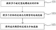
步骤101,提供多个被定型成螺旋状的杆体,多个所述杆体的远端结合在一起,每个所述杆体设置有电极。Step 101: Provide a plurality of rods shaped into a spiral shape, the distal ends of the plurality of rods are combined together, and each of the rods is provided with an electrode.
步骤103,将多个杆体的近端与内鞘管的远端连接,每个所述杆体绕所述内鞘管的轴向螺旋延伸设置。Step 103: Connect the proximal ends of the plurality of rods with the distal ends of the inner sheath, each of the rods spirally extending around the axial direction of the inner sheath.
步骤105,将所述内鞘管穿置于外鞘管内,将所述内鞘管的近端以及所述外鞘管的近端与手柄连接,所述消融组件能够在收缩状态与扩张状态之间切换,在所述收缩状态下,所述消融组件活动收容于所述外鞘管内;在所述扩张状态下,所述消融组件的近端从所述外鞘管的远端露出,并且每个电极偏离其所在杆体上螺旋角最大的位置。Step 105: Put the inner sheath tube into the outer sheath tube, connect the proximal end of the inner sheath tube and the proximal end of the outer sheath tube to the handle, and the ablation assembly can be in a contracted state and an expanded state. In the contracted state, the ablation assembly is movably contained in the outer sheath; in the expanded state, the proximal end of the ablation assembly is exposed from the distal end of the outer sheath, and each Each electrode deviates from the position with the largest helix angle on the rod where it is located.
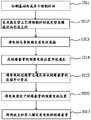
请参阅图12,步骤101,具体包括以下步骤:Please refer to Figure 12,
步骤1011,切割基材形成多个预制杆材,相邻的两个预制杆材之间形成切割缝,所述切割缝从所述基材的第一端延伸并贯穿所述基材的第二端的端面,使得所述多个主杆的远端结合于一起。
换而言之,将基材,比如管材,切割出多个预制杆材,基材的近端不切割,即所有的预制杆材的近端固定连接于一起;或者,基材的远端不切割,即所有的预制杆材的远端固定连接于一起。预制杆材为直杆,基材由镍钛合金、不锈钢或者高分子材料制成。可以理解,不限定预制杆材为直杆。可以理解,可以通过切割基材形成多个独立且相互分离设置的预制杆材,例如,在一种实施方式中,预制杆材就是一段镍钛合金丝,不需要将管状基材沿轴向切割。将镍钛合金丝分切成多段即可。In other words, the substrate, such as a tube, is cut into multiple prefabricated rods, and the proximal end of the substrate is not cut, that is, the proximal ends of all the prefabricated rods are fixedly connected together; or, the distal end of the substrate is not Cutting, that is, the distal ends of all prefabricated rods are fixedly connected together. The prefabricated rod is a straight rod, and the base material is made of nickel-titanium alloy, stainless steel or polymer materials. It can be understood that the prefabricated rods are not limited to straight rods. It is understandable that a plurality of independent and separate prefabricated rods can be formed by cutting the substrate. For example, in one embodiment, the prefabricated rod is a piece of nickel-titanium alloy wire, and there is no need to cut the tubular substrate in the axial direction. . Cut the nickel-titanium alloy wire into multiple sections.
步骤1012,采用热定型工艺将预制杆材热定型成螺旋状而形成主杆,所述主杆沿所述内鞘管的轴向螺旋延伸设置,多个所述主杆的远端结合在一起。
本实施方式中,通过热定型工具对每个预制杆材进行热定型加工。通过热定型工具分 步对每个预制杆材热定型至所需螺旋角,比如第一次定型至45度,第二次定型至90度……,最终定型至所需螺旋角,防止一次性定型至所需螺旋角而导致预制杆材断裂和/或扭曲。可以理解,在预制杆材就是一段镍钛合金丝的实施方式中,可以通过热定型工具一步成型所需杆体。In this embodiment, each prefabricated rod is heat-set by a heat-setting tool. Heat setting each prefabricated rod to the required helix angle step by step through the heat setting tool, such as the first setting to 45 degrees, the second setting to 90 degrees..., and the final setting to the required helix angle to prevent one-off Shaping to the required helix angle causes the prefabricated rod to break and/or twist. It can be understood that in the embodiment where the prefabricated rod material is a piece of nickel-titanium alloy wire, the required rod body can be formed in one step by a heat setting tool.
可以理解,不限定用热定型工具对预制杆材加工形成主杆,也可以通过采用其他方式制备。It can be understood that it is not limited to use a heat setting tool to process the prefabricated rod to form the main rod, and it can also be prepared by other methods.
步骤1013,将电极与导线固定并电性连接。本实施方式中,电极与导线焊接于一起。可以理解,电极与导线也可以通过其他方式连接,例如通过胶体连接。
步骤1014,在绝缘套管的预装电极位置开设通孔,所述通孔偏离所述杆体的弯曲度最大的位置。
步骤1015,将导线的近端穿过通孔并从绝缘套管的近端开口穿出。Step 1015: Pass the proximal end of the wire through the through hole and out of the proximal opening of the insulating sleeve.
步骤1016,将电极固定于绝缘套管的预装电极位置上。Step 1016: Fix the electrode on the pre-installed electrode position of the insulating sleeve.
步骤1017,将所述主杆穿入固定有电极的绝缘套管,所述导线夹设于绝缘套管的内壁与主杆之间并相互绝缘从而形成所述杆体。In
步骤101中,若已备有预制杆材,则省略步骤1011。In
所述步骤103,即所述将多个杆体的近端与内鞘管的远端连接,包括:导线的远端从内鞘管的远端穿入并从内鞘管的近端穿出且与手柄上的连接器电连接,以及主杆的近端与内鞘管的远端固定连接。The
可以理解,在一些实施方式中,步骤105之前与步骤103之后,或者在步骤105之后,还包括步骤:将牵引导杆穿设于内鞘管并露出所述内鞘管的远端,所述多个杆体的远端与所述牵引导杆的远端固定于一起。It can be understood that, in some embodiments, before
需要说明的是,为说明简便引入了以上步骤标号,比如101、1015等,以上步骤标号不用于限定步骤之间的先后关系。It should be noted that the above step labels, such as 101, 1015, etc., are introduced for the sake of simplicity, and the above step labels are not used to limit the sequence of steps.
所述制备方法还包括步骤:将弹性支撑结构设置在所述消融组件的近端、所述消融组件的远端、所述消融组件的中部中的至少一个,所述消融组件的中部位于所述消融组件的近端与所述消融组件的远端之间区域,用于使两个相邻的杆体相互之间保持间距,防止在消融装置在工作过程中,因为杆体之间间距过小导致电极产出电弧或者电火花,造成对目标组织的击穿伤害。弹性支撑结构可以通过粘接或焊接的方式设置于消融组件上。The preparation method further includes the step of: arranging an elastic support structure on at least one of the proximal end of the ablation component, the distal end of the ablation component, and the middle of the ablation component, where the middle of the ablation component is located in the ablation component. The area between the proximal end of the ablation component and the distal end of the ablation component is used to keep two adjacent rods at a distance from each other to prevent electrodes from being caused by the small distance between the rods during the operation of the ablation device Produce electric arcs or sparks, causing breakdown damage to the target tissue. The elastic support structure can be arranged on the ablation component by bonding or welding.
本实施方式中,所述弹性支撑结构为由镍钛丝制成的网状结构,所述弹性支撑结构沿所述消融组件的周向设置。所述弹性支撑结构包覆杆体的远端段。所述弹性支撑结构与所有的杆体连接。所述弹性支撑结构能够随同所述消融组件的外径而变化形状。In this embodiment, the elastic support structure is a mesh structure made of nickel-titanium wire, and the elastic support structure is arranged along the circumferential direction of the ablation component. The elastic support structure covers the distal end section of the rod body. The elastic support structure is connected with all the rod bodies. The elastic support structure can change shape along with the outer diameter of the ablation component.
可以理解,所述弹性支撑结构还可以是其他支撑件,比如设置在相邻杆体之间的支撑条/杆,以及杆体上设置的用于电极之间隔离的部件。It can be understood that the elastic support structure may also be other supports, such as support bars/rods arranged between adjacent rods, and components for isolation between electrodes arranged on the rods.
以上所揭露的仅为本申请较佳实施方式而已,当然不能以此来限定本申请之权利范围,因此依本申请权利要求所作的等同变化,仍属本申请所涵盖的范围。The above-disclosed are only the preferred implementations of the application, which of course cannot be used to limit the scope of rights of the application. Therefore, equivalent changes made in accordance with the claims of the application still fall within the scope of the application.
Claims (18)
Translated fromChineseApplications Claiming Priority (4)
| Application Number | Priority Date | Filing Date | Title |
|---|---|---|---|
| CN202010287213.2ACN113440246A (en) | 2020-04-13 | 2020-04-13 | Ablation device and method of making same |
| CN202020539132.2 | 2020-04-13 | ||
| CN202010287213.2 | 2020-04-13 | ||
| CN202020539132.2UCN213465297U (en) | 2020-04-13 | 2020-04-13 | Ablation device |
Publications (1)
| Publication Number | Publication Date |
|---|---|
| WO2021208847A1true WO2021208847A1 (en) | 2021-10-21 |
Family
ID=78084030
Family Applications (1)
| Application Number | Title | Priority Date | Filing Date |
|---|---|---|---|
| PCT/CN2021/086580CeasedWO2021208847A1 (en) | 2020-04-13 | 2021-04-12 | Ablation device and preparation method therefor |
Country Status (1)
| Country | Link |
|---|---|
| WO (1) | WO2021208847A1 (en) |
Cited By (6)
| Publication number | Priority date | Publication date | Assignee | Title |
|---|---|---|---|---|
| CN114271926A (en)* | 2021-11-19 | 2022-04-05 | 杭州德诺电生理医疗科技有限公司 | Ablation catheter |
| CN114343835A (en)* | 2021-12-16 | 2022-04-15 | 上海玮启医疗器械有限公司 | Pulse ablation electrode device and ablation catheter |
| CN115153814A (en)* | 2022-06-23 | 2022-10-11 | 上海玮琅医疗科技有限公司 | Bracket type radio frequency ablation catheter |
| CN115349947A (en)* | 2022-07-28 | 2022-11-18 | 杭州睿笛生物科技有限公司 | Intracavity high-voltage pulse ablation electrode |
| CN115645036A (en)* | 2022-01-25 | 2023-01-31 | 洲瓴(上海)医疗器械有限公司 | Pulse ablation device |
| CN117481787A (en)* | 2023-10-11 | 2024-02-02 | 上海玮启医疗器械有限公司 | Pulmonary vein isolation catheter |
Citations (13)
| Publication number | Priority date | Publication date | Assignee | Title |
|---|---|---|---|---|
| US20020177765A1 (en)* | 2001-05-24 | 2002-11-28 | Bowe Wade A. | Ablation and high-resolution mapping catheter system for pulmonary vein foci elimination |
| US20070100390A1 (en)* | 2000-10-17 | 2007-05-03 | Asthmatx, Inc. | Modification of airways by application of energy |
| CN101309651A (en)* | 2005-06-20 | 2008-11-19 | 消融前沿公司 | Ablation catheter |
| CN101797181A (en)* | 2008-12-30 | 2010-08-11 | 韦伯斯特生物官能公司 | Catheter with multiple electrode assemblies for use at or near tubular regions of the heart |
| CN103750899A (en)* | 2014-01-21 | 2014-04-30 | 深圳市惠泰医疗器械有限公司 | Multi-electrode basket catheter and manufacture method thereof |
| CN104434083A (en)* | 2013-09-16 | 2015-03-25 | 韦伯斯特生物官能(以色列)有限公司 | Basket catheter with deflectable spine |
| CN104869932A (en)* | 2013-01-31 | 2015-08-26 | 雷纳尔动力有限公司 | Unipolar and/or Bipolar Ablation Catheters |
| CN105073051A (en)* | 2013-03-08 | 2015-11-18 | 圣犹达医疗用品电生理部门有限公司 | Basket for multi-electrode array catheter |
| CN105263432A (en)* | 2013-08-14 | 2016-01-20 | 拉维塔技术有限公司 | Methods and apparatuses for treating auto-immune diseases by ablative neuromodulation |
| CN106687168A (en)* | 2014-09-12 | 2017-05-17 | X-节奏有限责任公司 | Multi-electrode mapping catheter |
| CN107440787A (en)* | 2016-06-01 | 2017-12-08 | 四川锦江电子科技有限公司 | A kind of basket shape ablation catheter and ablating device |
| CN109199581A (en)* | 2014-08-05 | 2019-01-15 | 上海魅丽纬叶医疗科技有限公司 | Radio frequency ablation catheter and its equipment with network management shape supporting structure |
| CN212630880U (en)* | 2020-06-28 | 2021-03-02 | 杭州诺茂医疗科技有限公司 | Ablation device and ablation system |
- 2021
- 2021-04-12WOPCT/CN2021/086580patent/WO2021208847A1/ennot_activeCeased
Patent Citations (13)
| Publication number | Priority date | Publication date | Assignee | Title |
|---|---|---|---|---|
| US20070100390A1 (en)* | 2000-10-17 | 2007-05-03 | Asthmatx, Inc. | Modification of airways by application of energy |
| US20020177765A1 (en)* | 2001-05-24 | 2002-11-28 | Bowe Wade A. | Ablation and high-resolution mapping catheter system for pulmonary vein foci elimination |
| CN101309651A (en)* | 2005-06-20 | 2008-11-19 | 消融前沿公司 | Ablation catheter |
| CN101797181A (en)* | 2008-12-30 | 2010-08-11 | 韦伯斯特生物官能公司 | Catheter with multiple electrode assemblies for use at or near tubular regions of the heart |
| CN104869932A (en)* | 2013-01-31 | 2015-08-26 | 雷纳尔动力有限公司 | Unipolar and/or Bipolar Ablation Catheters |
| CN105073051A (en)* | 2013-03-08 | 2015-11-18 | 圣犹达医疗用品电生理部门有限公司 | Basket for multi-electrode array catheter |
| CN105263432A (en)* | 2013-08-14 | 2016-01-20 | 拉维塔技术有限公司 | Methods and apparatuses for treating auto-immune diseases by ablative neuromodulation |
| CN104434083A (en)* | 2013-09-16 | 2015-03-25 | 韦伯斯特生物官能(以色列)有限公司 | Basket catheter with deflectable spine |
| CN103750899A (en)* | 2014-01-21 | 2014-04-30 | 深圳市惠泰医疗器械有限公司 | Multi-electrode basket catheter and manufacture method thereof |
| CN109199581A (en)* | 2014-08-05 | 2019-01-15 | 上海魅丽纬叶医疗科技有限公司 | Radio frequency ablation catheter and its equipment with network management shape supporting structure |
| CN106687168A (en)* | 2014-09-12 | 2017-05-17 | X-节奏有限责任公司 | Multi-electrode mapping catheter |
| CN107440787A (en)* | 2016-06-01 | 2017-12-08 | 四川锦江电子科技有限公司 | A kind of basket shape ablation catheter and ablating device |
| CN212630880U (en)* | 2020-06-28 | 2021-03-02 | 杭州诺茂医疗科技有限公司 | Ablation device and ablation system |
Cited By (7)
| Publication number | Priority date | Publication date | Assignee | Title |
|---|---|---|---|---|
| CN114271926A (en)* | 2021-11-19 | 2022-04-05 | 杭州德诺电生理医疗科技有限公司 | Ablation catheter |
| CN114271926B (en)* | 2021-11-19 | 2024-03-19 | 杭州德诺电生理医疗科技有限公司 | ablation catheter |
| CN114343835A (en)* | 2021-12-16 | 2022-04-15 | 上海玮启医疗器械有限公司 | Pulse ablation electrode device and ablation catheter |
| CN115645036A (en)* | 2022-01-25 | 2023-01-31 | 洲瓴(上海)医疗器械有限公司 | Pulse ablation device |
| CN115153814A (en)* | 2022-06-23 | 2022-10-11 | 上海玮琅医疗科技有限公司 | Bracket type radio frequency ablation catheter |
| CN115349947A (en)* | 2022-07-28 | 2022-11-18 | 杭州睿笛生物科技有限公司 | Intracavity high-voltage pulse ablation electrode |
| CN117481787A (en)* | 2023-10-11 | 2024-02-02 | 上海玮启医疗器械有限公司 | Pulmonary vein isolation catheter |
Similar Documents
| Publication | Publication Date | Title |
|---|---|---|
| WO2021208847A1 (en) | Ablation device and preparation method therefor | |
| WO2022171142A1 (en) | Ablation catheter, ablation device and ablation system | |
| CN213465297U (en) | Ablation device | |
| CN108784896B (en) | Interatrial ostomy device, interatrial ostomy system and method of operating the same | |
| EP4467091A1 (en) | Ablation device | |
| CN212630880U (en) | Ablation device and ablation system | |
| US20230130692A1 (en) | Ablation Device and Ablation System | |
| CN111772783A (en) | Ablation system with bendable electrodes | |
| US20220249159A1 (en) | Systems and Devices for Ablation with Bendable Electrodes | |
| CN114366286B (en) | Ablation Catheter | |
| CN113440243A (en) | Ablation device and ablation system | |
| JP2005512609A (en) | Spiral electrophysiology catheter | |
| CN113576655A (en) | High-pressure-resistance ablation catheter | |
| CN114271926A (en) | Ablation catheter | |
| CN114191071B (en) | Ablation Device | |
| CN109259852B (en) | ostomy device | |
| CN113995504B (en) | Ablation device | |
| CN113440246A (en) | Ablation device and method of making same | |
| CN213851011U (en) | Ablation catheter with bendable electrodes | |
| WO2022135424A1 (en) | Left atrial appendage ablation device and control method | |
| CN216090750U (en) | High-pressure-resistance ablation catheter | |
| EP4115832A1 (en) | Pulsed field ablation catheter | |
| CN112120780A (en) | Atrial septostomy device | |
| CN118044876A (en) | Ablation catheter and ablation system | |
| CN116407253A (en) | Ablation occlusion system |
Legal Events
| Date | Code | Title | Description |
|---|---|---|---|
| 121 | Ep: the epo has been informed by wipo that ep was designated in this application | Ref document number:21787743 Country of ref document:EP Kind code of ref document:A1 | |
| NENP | Non-entry into the national phase | Ref country code:DE | |
| 122 | Ep: pct application non-entry in european phase | Ref document number:21787743 Country of ref document:EP Kind code of ref document:A1 |