WO2021208273A1 - System for identifying state parameters, hoisting positioning system, and hoisting apparatus - Google Patents
System for identifying state parameters, hoisting positioning system, and hoisting apparatusDownload PDFInfo
- Publication number
- WO2021208273A1 WO2021208273A1PCT/CN2020/101022CN2020101022WWO2021208273A1WO 2021208273 A1WO2021208273 A1WO 2021208273A1CN 2020101022 WCN2020101022 WCN 2020101022WWO 2021208273 A1WO2021208273 A1WO 2021208273A1
- Authority
- WO
- WIPO (PCT)
- Prior art keywords
- hoisting
- hook
- center
- target
- point
- Prior art date
- Legal status (The legal status is an assumption and is not a legal conclusion. Google has not performed a legal analysis and makes no representation as to the accuracy of the status listed.)
- Ceased
Links
Images


Classifications
- B—PERFORMING OPERATIONS; TRANSPORTING
- B66—HOISTING; LIFTING; HAULING
- B66C—CRANES; LOAD-ENGAGING ELEMENTS OR DEVICES FOR CRANES, CAPSTANS, WINCHES, OR TACKLES
- B66C13/00—Other constructional features or details
- B66C13/18—Control systems or devices
- B66C13/46—Position indicators for suspended loads or for crane elements
- B—PERFORMING OPERATIONS; TRANSPORTING
- B66—HOISTING; LIFTING; HAULING
- B66C—CRANES; LOAD-ENGAGING ELEMENTS OR DEVICES FOR CRANES, CAPSTANS, WINCHES, OR TACKLES
- B66C13/00—Other constructional features or details
- B66C13/04—Auxiliary devices for controlling movements of suspended loads, or preventing cable slack
- B66C13/06—Auxiliary devices for controlling movements of suspended loads, or preventing cable slack for minimising or preventing longitudinal or transverse swinging of loads
- B66C13/063—Auxiliary devices for controlling movements of suspended loads, or preventing cable slack for minimising or preventing longitudinal or transverse swinging of loads electrical
- B—PERFORMING OPERATIONS; TRANSPORTING
- B66—HOISTING; LIFTING; HAULING
- B66C—CRANES; LOAD-ENGAGING ELEMENTS OR DEVICES FOR CRANES, CAPSTANS, WINCHES, OR TACKLES
- B66C13/00—Other constructional features or details
- B66C13/04—Auxiliary devices for controlling movements of suspended loads, or preventing cable slack
- B66C13/08—Auxiliary devices for controlling movements of suspended loads, or preventing cable slack for depositing loads in desired attitudes or positions
- B66C13/085—Auxiliary devices for controlling movements of suspended loads, or preventing cable slack for depositing loads in desired attitudes or positions electrical
- B—PERFORMING OPERATIONS; TRANSPORTING
- B66—HOISTING; LIFTING; HAULING
- B66C—CRANES; LOAD-ENGAGING ELEMENTS OR DEVICES FOR CRANES, CAPSTANS, WINCHES, OR TACKLES
- B66C13/00—Other constructional features or details
- B66C13/16—Applications of indicating, registering, or weighing devices
- B—PERFORMING OPERATIONS; TRANSPORTING
- B66—HOISTING; LIFTING; HAULING
- B66C—CRANES; LOAD-ENGAGING ELEMENTS OR DEVICES FOR CRANES, CAPSTANS, WINCHES, OR TACKLES
- B66C13/00—Other constructional features or details
- B66C13/18—Control systems or devices
- B66C13/40—Applications of devices for transmitting control pulses; Applications of remote control devices
- B66C13/44—Electrical transmitters
- B—PERFORMING OPERATIONS; TRANSPORTING
- B66—HOISTING; LIFTING; HAULING
- B66C—CRANES; LOAD-ENGAGING ELEMENTS OR DEVICES FOR CRANES, CAPSTANS, WINCHES, OR TACKLES
- B66C13/00—Other constructional features or details
- B66C13/18—Control systems or devices
- B66C13/48—Automatic control of crane drives for producing a single or repeated working cycle; Programme control
Definitions
- the inventionrelates to the technical field of engineering measurement, in particular to a system for identifying state parameters, a hoisting positioning system and hoisting equipment.
- the wire rope connected to the boomwill be affected by the gravity and inertia of the hook or load, which will cause the hook and its load to sway to a certain degree.
- the swing of the hookis not conducive to the lifting of the crane and the placement of the suspended objects, thereby affecting the operating efficiency of the crane.
- italso poses a certain threat to the personal safety and property safety of the site.
- the prior artmainly uses multiple cameras to collect multiple images, and then stitches and processes the collected multiple images to realize the measurement of the posture of the hook.
- the above methodis relatively cumbersome, and certain errors may be introduced in the process of stitching and processing multiple images, which ultimately leads to inaccurate measurement results of the hook posture.
- the purpose of the present inventionis to provide a system for identifying state parameters, a hoisting positioning system and hoisting equipment, which can effectively identify the state parameters involved in the hoisting process, and can realize the automatic hoisting process according to the identified state parameters, For example, not only can the swing angle of the hook be prevented from being too large, but also the effective positioning of the hoisting process can be realized.
- the first aspect of the present inventionprovides a system for identifying state parameters.
- the systemincludes: an image acquisition device for acquiring preset tags including the upper side of the target object involved in the hoisting process. The top view image of the preset field of view within the device; and a state parameter recognition device for calculating the state parameters in the hoisting process by using a visual recognition method based on the top view image of the preset field of view and a specific geometric relationship.
- the state parameter identification deviceincludes: a pixel size obtaining module, configured to obtain the pixel size of the preset label based on the top view image of the preset field of view; a pixel physical size calculation module, configured to obtain the pixel size based on the The pixel size and physical size of the preset label are calculated to calculate the physical size of a unit pixel; and a state parameter calculation module is used to calculate the top view image based on the physical size of the unit pixel, the preset field of view, and the specific geometric relationship, Calculate the state parameters in the hoisting process.
- the systemfurther includes: an image acquisition device for acquiring the top view image of the preset field of view including the preset tag, and sending the top view image to the image acquiring device.
- an image acquisition devicefor acquiring the top view image of the preset field of view including the preset tag, and sending the top view image to the image acquiring device.
- the systemfurther includes: a wireless transmission device for wirelessly transmitting the overhead image collected by the image acquisition device to the image acquisition device.
- the wireless transmission deviceis a wireless network bridge
- the wireless network bridgeincludes: a wireless transmitting end installed at the top of the boom; The wireless receiver where the transmitter is set face to face.
- the image acquisition deviceis a monocular camera installed on the top of the boom.
- the systemfurther includes: an angle sensor for collecting the tilt angle of the top of the boom; and a first distance sensor , For collecting the height of the top of the boom from the ground; and a first control device for adjusting the angle of the monocular camera according to the tilt angle of the top of the boom, so that the center of the optical axis is always perpendicular to the ground And adjust the focal length of the monocular camera according to the height of the top of the boom from the ground to keep the size of the target object consistent in the top view image.
- the state parameter calculation moduleincludes: a first pixel coordinate acquisition unit, configured to be based on the preset The top view image of the field of view, obtaining the pixel coordinates of the center of the preset label relative to the center of the top view image, wherein the center of the top view image is the projection point of the top of the boom on the top view image; and a pendulum An angle calculation unit, configured to calculate the pixel coordinates of the center of the preset label relative to the center of the top view image, the physical size of the unit pixel, the distance from the top of the boom to the hook, and the first triangle Relationship, calculate the swing angle of the hook.
- the swing angle calculation unitincludes: a distance calculation component for calculating the preset label based on the pixel coordinates of the center of the preset label relative to the center of the top view image and the physical size of the unit pixel The actual distance from the center of the tag to the center of the top view image; and a swing angle calculation component for calculating the actual distance from the center of the preset tag to the center of the top view image, and the top of the boom to the crane The distance between the hooks and the first triangle relationship is calculated, and the swing angle of the hook is calculated.
- the swing angle calculation component used to calculate the swing angle of the hookincludes: calculating the swing angle ⁇ of the hook according to the sine formula (1), Wherein, L DB is the actual distance from the center of the preset label to the center of the top view image; L OB is the distance from the top of the boom to the hook.
- the systemfurther includes: a current state parameter acquisition device for acquiring the current rotation angle and the current luffing length of the hoisting equipment, correspondingly, when the target object is a hoisting point or an in-position point and the
- the state parameteris the target rotation angle and the target luffing length of the hoisting equipment when the hook moves to the hoisting point or the in-situ point
- the state parameter calculation moduleincludes: second pixel coordinate acquisition Unit for obtaining the pixel coordinates of the center of the preset label relative to the center of the top view image based on the top view image within the preset field of view, wherein the center of the top view image is the The projection point on the top view image; and a rotation angle and variable length calculation unit for calculating the pixel coordinates of the center of the preset label relative to the center of the top view image, the physical size of the unit pixel, and the The current swing angle of the hoisting equipment and the current luffing length and the second triangle relationship are calculated, and the target swing angle and the
- the rotation angle and luffing length calculation unitincludes: a physical coordinate calculation component for calculating the pixel coordinates of the center of the preset label relative to the center of the overhead image and the physical size of the unit pixel, Calculate the physical coordinates of the center of the preset label relative to the center of the top view image; a rotation angle calculation component is used to calculate the physical coordinates of the center of the preset tag relative to the center of the top view image, and the lifting The current turning angle of the equipment, the current luffing length and the second triangle relationship, calculating the target turning angle of the hoisting equipment when the hook moves to the hoisting point or the in-situ point; and calculating the luffing length Component for calculating the hook operation to the second triangle relationship based on the physical coordinates of the center of the preset label relative to the center of the top view image The target luffing length of the hoisting equipment at the hoisting point or the in-situ point.
- the rotation angle calculation componentis used to calculate the target rotation angle of the hoisting equipment when the hook moves to the lifting point or the in-situ point, including: based on the center of the preset label relative to the The physical coordinates ( ⁇ X, ⁇ Y) of the center of the top view image, the current rotation angle ⁇ current of the hoisting equipment and the current luffing length R current and the following formulas are used to calculate that the hook moves to the lifting point or the seating point
- the luffing length calculation componentis used to calculate the target luffing length of the hoisting equipment when the lifting point or the in-situ point is reached, including: relative to the center of the preset label based on The physical coordinates ( ⁇ X, ⁇ Y) of the center of the image, the current luffing length R current of the hoisting equipment and the following formulas are used to calculate the target change of the hoisting equipment when the hoisting point or the in
- the systemfurther includes: a second distance sensor for collecting the height of the hook from the ground.
- the state parameter calculation moduleincludes: a first height acquiring unit configured to acquire the predetermined height of the boom tip from the upper side of the target object Set the height of the tag; a second height obtaining unit for obtaining the height of the boom top from the hook according to the height of the boom top from the ground and the height of the hook from the ground; and height calculation Unit for calculating the distance from the hook to the target object according to the height of the top of the boom from the preset label on the upper side of the target object and the height of the top of the boom from the hook The target height of the preset label on the side.
- the first height acquiring unit for acquiring the height of the top of the boom from the preset label on the upper side of the target objectincludes: calculating the height of the tip of the boom from the upper side of the target object according to the following formula
- the present inventioncreatively obtains the top view image of the preset field of view including the preset label on the upper side of the target object, and then calculates the hoisting process based on the top view image and the specific geometric relationship and using the visual recognition method
- the state parameters in the hoisting processcan be effectively identified.
- the automatic hoisting processcan be realized. For example, it can not only prevent the swing angle of the hook from being too large, but also realize the effective positioning of the hoisting process .
- a second aspect of the present inventionprovides a hoisting positioning system.
- the hoisting positioning systemincludes: the system for identifying status parameters; State parameters control the actions of the corresponding actuators of the hoisting equipment to realize the automatic hoisting process.
- the hoisting positioning systemfurther includes: a comparing device for comparing the swing angle of the hook with a swing angle threshold, correspondingly
- the second control deviceis used to control the action of the actuator of the hoisting equipment, including: in the case that the swing angle of the hook is equal to the swing angle threshold, controlling the application of the hook to the boom The force of the swing angle in the opposite direction prevents the swing angle of the hook from being too large.
- the state parameters of the hoisting processare the target rotation angle of the hoisting equipment, the target luffing length, and the target height of the hook from the target object when the hook moves to the hoisting point or the seating point
- the second control deviceis used to control the corresponding actuator actions of the hoisting equipment including: according to the current rotation angle of the hoisting equipment, the current luffing length, and the current height of the hook to the ground, the target rotation The angle, the target luffing length and the target height of the hook from the preset label on the upper side of the target object are controlled to control the actions of the corresponding actuators of the lifting equipment to make the hook run to the lifting point Or the in-situ point.
- the second control device used to control the action of the corresponding actuator of the hoisting equipmentincludes: controlling the corresponding actuator to stop the action in advance through a preset strategy, so that the hook can accurately run to the hoisting Point or the in-situ point.
- the second control deviceincludes: a rotation control module, configured to control the rotation mechanism to stop the rotation action when the difference between the target rotation angle and the current rotation angle is equal to a rotation angle threshold; Module for controlling the luffing mechanism to stop the luffing action when the difference between the target luffing length and the current luffing length is equal to the luffing length threshold; and a hoisting control module for the hoist When the difference between the target height of the hook to the ground and the current height of the hook to the ground is equal to the hoisting height threshold, the hoisting mechanism is controlled to stop the hoisting action.
- a rotation control moduleconfigured to control the rotation mechanism to stop the rotation action when the difference between the target rotation angle and the current rotation angle is equal to a rotation angle threshold
- a hoisting control modulefor the hoist
- the present inventioncreatively controls the actions of the corresponding actuators of the hoisting equipment to realize the automatic hoisting process through the state parameters obtained by the above-mentioned system, thus, the automatic hoisting process can be realized, for example, not only can the hook swing angle be prevented from being excessive Large, it can also realize the effective positioning of the hoisting process.
- a third aspect of the present inventionprovides a hoisting equipment, the hoisting equipment includes: the hoisting positioning system.
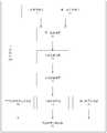
- Figure 1is a structural diagram of a system for identifying state parameters provided by an embodiment of the present invention
- Figure 2is a structural diagram of a system for identifying state parameters provided by an embodiment of the present invention
- Figure 3is a schematic structural diagram of a crane provided by an embodiment of the present invention.
- Figure 4is a structural diagram of a state parameter identification device provided by an embodiment of the present invention.
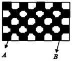
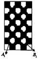
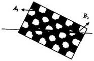
- Figures 5(a), 5(b) and 5(c)are respectively schematic diagrams of the checkerboard tags provided by the embodiments of the present invention presented in different top-view images;
- Fig. 6is a structural diagram of a state parameter calculation module provided by an embodiment of the present invention.
- FIG. 7is a schematic diagram of swing angle detection provided by an embodiment of the present invention.
- FIG. 8is a schematic diagram of a target offset provided by an embodiment of the present invention.
- FIG. 9is a schematic diagram of target height calculation provided by an embodiment of the present invention.
- Figure 10is a structural diagram of a hoisting positioning system provided by an embodiment of the present invention.
- FIG. 11is a schematic diagram of the operating state of the boom provided by the embodiment of the present invention.
- Fig. 12is a flowchart of a hoisting positioning process provided by an embodiment of the present invention.
- Image acquisition device20 State parameter recognition device
- Pixel size acquisition module24 Pixel physical size calculation module
- Second pixel coordinate acquisition unit 266Rotation angle and luffing length calculation unit
- FIG. 1is a structural diagram of a system for recognizing state parameters (hereinafter may be referred to as recognition system 100 for short) provided by an embodiment of the present invention.
- the recognition system 100may include: an image acquisition device 10 configured to acquire a top view image of a preset field of view including a preset label on the upper side of the target object involved in the hoisting process; and
- the state parameter recognition device 20, which can be connected to the image acquisition device 10,is used to calculate the hoisting process by using a visual recognition method based on the top view image of the preset field of view and a specific geometric relationship State parameters in.
- the target objectmay be a hook, a lifting point or an in-situ point, etc.
- the identification system 100may further include: an image capture device 30, which may be installed on the top of the boom for capturing the The top view image of the field of view is preset, and the top view image is sent to the image acquisition device 10.
- the image acquisition device 30may be a monocular camera 35 installed on the top of the boom, as shown in FIG. 3.
- the identification system 100may further include: an angle sensor 40, which may be installed on the top of the boom for collecting the tilt angle of the top of the boom; A distance sensor 50 for collecting the height of the top of the boom from the ground; and a first control device 60 that can be connected to the angle sensor 40 and the first distance sensor 50, Used to adjust the angle of the monocular camera according to the tilt angle of the top of the boom so that the center of its optical axis is always perpendicular to the ground; and adjust the focal length of the monocular camera according to the height of the top of the boom from the ground , So as to keep the size of the target object consistent in the overhead image.
- an angle sensor 40which may be installed on the top of the boom for collecting the tilt angle of the top of the boom
- a distance sensor 50for collecting the height of the top of the boom from the ground
- a first control device 60that can be connected to the angle sensor 40 and the first distance sensor 50, Used to adjust the angle of the monocular camera according to the tilt angle of the top of the boom so that the center of
- a pan/tilt head(not shown) can be set for self-checking on the monocular camera and the top of the boom, so that the first control device 60 can control the rotation of the pan/tilt according to the tilt angle of the top of the boom, so as to Adjust the angle of the monocular camera.
- This embodimentis based on the self-decision zooming method of monocular vision, which realizes automatic zooming in combination with the height of the top of the boom to the ground during the hoisting process, and realizes the online recognition and precise positioning of the hoisting or in-situ target with a height of ⁇ 100m and detection positioning.
- the accuracycan reach 3cm.
- the angle sensor 40may be a single-axis angle sensor 45.
- the inclination angle of the top of the boom collected by the single-axis angle sensor 45is 0, ensure that the axial direction of the single-axis angle sensor 45 is consistent with the direction of the body of the hoisting equipment (for example, crane) to ensure the measured angle data Validity;
- the first control device 60adjusts the angle of the monocular camera 35 so that its lens faces vertically downward.
- the first control device 60controls the rotation of the pan/tilt according to the collected tilt angle to adjust the center of the optical axis of the monocular camera 35 to be perpendicular to the ground.
- the height of the top of the boom to the ground collected by the first distance sensor 50also changes accordingly, so that the first control device 60 can adjust the focal length of the monocular camera 35 according to the collected height value.
- the preset field of viewmay at least include the field of view where the preset tag is located; and in the case where the target object is a lifting point (or seating point), so The preset field of view includes at least the field of view where the lifting point (or seating point) and the hook are located.
- the identification system 100may further include: a wireless transmission device 70, which may be installed on the boom, and used to capture the image collected by the image acquisition device 30
- the overhead imageis wirelessly transmitted to the image acquisition device 10. Therefore, the wireless transmission device 70 can realize the stable and reliable long-distance (for example, distance ⁇ 120m) transmission of the image data source, which can effectively solve the problem of the limited field of view of the manipulator, and monitor the hoisting scene in a large space in real time.
- the target objectplays a role in assisting and guiding the hoisting.
- the top view imagemay be a top view picture, a top view video image, or the like.
- the wireless transmission device 70may be a wireless network bridge.
- the wireless network bridgemay include: a wireless transmitting terminal 72 installed at the top of the boom; and a wireless receiving terminal 74 installed on the side of the base arm of the boom and arranged face to face with the wireless transmitting terminal 72, As shown in Figure 3. Wherein, the face-to-face arrangement of the wireless sending end 72 and the wireless receiving end 74 can realize the most effective wireless transmission of data.
- the state parameter identification device 20may include: a pixel size obtaining module 22, configured to obtain the pixel size of the preset label based on the top view image of the preset field of view; a pixel physical size calculation module 24.
- the pixel physical size calculation module 24can be connected to the pixel size acquisition module 22 for calculating the physical size of a unit pixel based on the pixel size and physical size of the preset label; and the state parameter calculation module 26 ,
- the state parameter calculation module 26 and the pixel physical size calculation module 24are configured to calculate the hoisting process based on the physical size of the unit pixel, the top view image of the preset field of view, and the specific geometric relationship State parameters in.
- the preset labelmay be a non-graphic label or a graphical label (for example, a checkerboard label).
- the pixel size acquisition module 22determines the pixel size occupied by the non-graphic label in the horizontal and vertical directions of the corresponding top view image, which are w 1 pixel and h 1 pixel , respectively;
- the physical size calculation module 24calculates the horizontal physical size and the vertical physical size of the unit pixel as L pixels x according to the pixel sizes w 1 pixel and h 1 pixel without graphic tags and the corresponding physical sizes W 1 actual and H 1 actual.
- the dotsare the detected feature corners of the target, no matter what state the boom is running in .
- the actual physical size between the target feature corner points(which can be referred to as the maximum internal corner point) at the two ends of the checkerboard label in the transverse direction (in the direction of AB, A 1 B 1 or A 2 B 2 ) is W 2 actual , W'2 actual and W" 2 actual ;
- the maximum internal corner coordinates of the checkerboard label in the transverse directionare A(x a , y a ), B(x b , y b )
- the pixel size acquisition module 22determines the pixel distance between the largest inner corner points in the horizontal direction (that is, the pixel size occupied by the checkerboard label in the horizontal direction) as:
- the pixel size occupied by the checkerboard label in the vertical directionis equal to the pixel size
- the physical size corresponding to the unit pixelcan be accurately calculated.
- the state parameter calculation module 26includes: a first pixel coordinate acquisition unit 260, configured to be based on the preset field of view A range of the top view image, obtaining the pixel coordinates of the center of the preset label relative to the center of the top view image, wherein the center of the top view image is the projection point of the top of the boom on the top view image; and a swing angle
- the calculation unit 262, the swing angle calculation unit 262may be connected to the first pixel coordinate acquisition unit 260, and is configured to be based on the pixel coordinates of the center of the preset label relative to the center of the top view image, and the unit
- the physical size of the pixel, the distance from the top of the boom to the hook, and the first triangle relationshipare used to calculate the swing angle of the hook, as shown in FIG. 6.
- the swing angle calculation unit 262may include: a distance calculation component (not shown) for calculating the pixel coordinates of the center of the preset label relative to the center of the overhead image and the physical value of the unit pixel. Size, calculating the actual distance from the center of the preset label to the center of the top view image; and a swing angle calculation component (not shown), which can be connected to the distance calculation component (Not shown) connected to calculate based on the actual distance from the center of the preset label to the center of the top view image, the distance from the top of the boom to the hook, and the first triangular relationship The swing angle of the hook.
- the swing angle calculation componentused to calculate the swing angle of the hook includes: calculating the swing angle ⁇ of the hook according to the sine formula (1),
- L DBis the actual distance from the center of the preset label to the center of the top view image
- L OBis the distance from the top of the boom to the hook.
- the projected point of the boom top on the image planeis the origin
- the horizontal central axis of the imageis the X axis
- the vertical central axisis the Y axis
- the direction perpendicular to the image planeis the Z axis to establish a three-dimensional
- the coordinate system(the three-dimensional coordinate system is the same unless otherwise specified in this article)
- the plane of the top view image of the preset field of view including the non-graphic label 1 on the upper side of the hookis parallel to the XY plane
- the center point Dis the projection point of the top O point of the boom on the overhead image.
- the pixel coordinates w 1 offset and h 1 offset of the center point B of the non-graphic label 1 relative to the point Dcan be obtained. Therefore, the offset of w 1, the offset of h 1 and the unit pixel can be obtained.
- the swing angle of the hookcan be calculated according to DB and the distance L OB from the top of the boom to the hook, combined with the above sine formula (1)
- the non-graphic labelcan be replaced with a checkerboard label or other suitable label, and the center of the preset label in the first triangle relationship used to calculate the swing angle of the hook can be replaced with this Preset any other geometric points in the label.
- a tagis installed on the upper side of the hook (for example, on the upper side of the pulley of the hook), and the yaw angle of the hook is calculated in real time online by means of visual inspection.
- the above-mentioned systemhas the advantages of low cost, low computational complexity, real-time performance and reliability, etc., and can be applied to the anti-swing control of the hook to realize smooth hoisting.
- the visual recognition technologyis combined with the data detected by the multi-sensor to identify the relative position offset vectors ⁇ X, ⁇ Y of the target object relative to the projection point of the top of the boom on the overhead image and the hook distance
- the target height ⁇ Z of the preset label on the upper side of the target objectcan be obtained when the hook moves to the target object.
- the identification system 100may further include: a current state parameter obtaining device 80, configured to obtain the current rotation angle and the current luffing length of the hoisting equipment.
- the state parameteris the target rotation angle and target amplitude of the hoisting equipment when the hook moves to the lifting point or the in-position point
- the state parameter calculation module 26may include: a second pixel coordinate obtaining unit 264, configured to obtain the center of the preset label relative to the top view image based on the top view image in the preset field of view.
- the physical dimensions of the hoisting equipment, the current rotation angle of the hoisting equipment and the current luffing length and the second triangle relationship, calculating the target rotation angle of the hoisting equipment when the hook moves to the hoisting point or the in-position point and The target luffing lengthis shown in Figure 6.
- the rotation angle and luffing length calculation unit 266may include: a physical coordinate calculation component (not shown), which is used to calculate the pixel coordinates based on the center of the preset label relative to the center of the top view image and all the pixels.
- the physical size of the unit pixelcalculate the physical coordinates of the center of the preset label relative to the center of the top view image; a rotation angle calculation component (not shown), the rotation angle calculation component (not shown) can be combined with
- the physical coordinate calculation component (not shown)is connected to the physical coordinates based on the center of the preset label relative to the center of the top view image, the current rotation angle and the current luffing length of the hoisting equipment, and
- the second triangular relationshipcalculates the target rotation angle of the hoisting equipment when the hook moves to the hoisting point or the seating point; and a luffing length calculation component (not shown), the luffing
- the length calculation component (not shown)can be connected to the physical coordinate calculation component (not shown), and is used
- the rotation angle calculation component(not shown) is used to calculate the target rotation angle of the hoisting equipment when the hook moves to the lifting point or the in-situ point, including: based on the preset label The physical coordinates ( ⁇ X, ⁇ Y) of the center relative to the center of the top view image, the current rotation angle ⁇ current of the hoisting equipment and the current luffing length R current and formula (2), calculate the operation to the lifting point or the lifting point The target rotation angle ⁇ target of the hoisting equipment at the positioning point,
- the luffing length calculation component(not shown) is used to calculate the target luffing length of the hoisting equipment when the lifting point or the in-situ point is reached, including: based on the preset label The physical coordinates of the center relative to the center of the image ( ⁇ X, ⁇ Y), the current luffing length of the hoisting equipment R current and formula (3), calculate when the hook moves to the hoisting point or the in-position point The target luffing length of the hoisting equipment,
- FIG. 8shows the plane where the top view image of the preset field of view including the checkerboard label 2 on the upper side of the hook is located, and the center D point (x D , y D ) of the top view image is the arm
- the projection point of the top O point on the top view image, and the pixel coordinates of the corner point corresponding to the center C point of the checkerboard label 2are (x c , y c ).
- the current rotation angle and the current luffing length of the hoisting equipmentcan be collected and acquired by a rotation angle sensor and a length sensor, respectively.
- the target rotation anglecan be estimated
- the length R of the current amplitude of the currentcan be estimated target amplitude length
- the boomis determined
- the identification system 100may further include: a second distance sensor 90 for collecting the height of the hook from the ground.
- the state parameter calculation module 26Including: a first height acquiring unit 268, configured to acquire the height of the top of the boom from the preset label on the upper side of the target object; a second height acquiring unit 270, the second height acquiring unit 270 can interact with the The second distance sensor 90 is connected to obtain the height of the boom top from the hook according to the height of the boom top from the ground and the height of the hook from the ground; and a height calculation unit 272,
- the height calculation unit 272can be connected to the first height acquisition unit 268 and the second height acquisition unit 270, and is configured to determine the height of the preset tag on the upper side of the target object from the top of the boom. And the height of the top of the boom from the hook
- the first height obtaining unit 268 for obtaining the height of the top of the boom from the preset label on the upper side of the target objectmay include: calculating the top of the boom from the target object according to formula (4) The height of the preset label on the upper side is H1,
- fis the focal length of the monocular camera
- L pixelis the physical size of the unit pixel.
- the lifting point of the target objectis taken as an example.
- the height H1 of the camera (or the top of the boom) relative to the lifting pointis calculated by formula (4); and the difference between the boom top and boom height H of the hook from the ground height from the ground of the hook H, to give a height H2 from the top of the boom to the hook; and finally obtaining the camera (Or the top of the boom)
- the hoisting mechanism's lifting (up and down) directionwhen Z>0, hoist down (lower); when Z ⁇ 0, roll Raise (rise).
- the checkerboard labelcan be replaced with a non-graphic label or other suitable label, and the above-mentioned calculation can be used to calculate the lifting point when the hook is moved to the lifting point or the seating point.
- the center of the preset label in the triangular relationship between the target luffing length of the device and the target rotation angleis replaced with any other geometric point in the preset label.
- the above embodimentscan be applied to various complex hoisting scenarios such as ground hoisting, high platform hoisting and side hoisting.
- the target rotation angle and target luffing length of the hoisted object or the positioning pointcan be calculated through real-time online target detection.
- the hookis used for controlled positioning, which can realize the precise positioning problem when the lifting object or the seating point is blocked.
- the present inventioncreatively obtains a top view image of a preset field of view including a preset label on the upper side of the target object, and then calculates the hoisting process based on the top view image and a specific geometric relationship using a visual recognition method.
- the state parameters in the hoisting processthe state parameters involved in the hoisting process can be effectively identified.
- the automatic hoisting processcan be realized. For example, it can not only prevent the swing angle of the hook from being too large, but also realize the effective positioning of the hoisting process .
- the embodiment of the present inventionalso provides a structural diagram of a hoisting positioning system.
- the hoisting positioning systemmay include: the system for identifying status parameters (referred to as the identification system 100 for short); and a second control device 200, which may be connected to the identification system 100, According to the status parameters of the hoisting process acquired by the identification system 100, the corresponding actuators of the hoisting equipment act to realize the automatic hoisting process.
- the hoisting positioning systemmay further include: a comparison device (not shown), and the comparison device (not shown) and the identification system 100 It is connected to the second control device 200 and is used to compare the swing angle of the hook with the swing angle threshold.
- the second control device 200is used to control the action of the actuator of the hoisting equipment, including: in the case that the swing angle of the hook is equal to the swing angle threshold, controlling the application of the lifting hook to the swing angle threshold.
- the swing angle of the hookhas a force in the opposite direction to prevent the swing angle of the hook from being too large.
- the implementation of this embodimentis simple, and the hook anti-sway control can be effectively performed.
- the state parametersare the target rotation angle of the hoisting equipment when the hook moves to the hoisting point or the in-position point, the target luffing length, and the target height of the hook from the target object, and the current state parameters are all
- the second control device 200is used to control the corresponding actuator actions of the hoisting equipment including: according to the The current swivel angle of the hoisting equipment, the current luffing length and the current height of the hook to the ground, the target swivel angle, the target luffing length, and the preset label where the hook is above the target object Control the action of the corresponding actuator of the hoisting equipment to make the hook move to the hoisting point or the seating point.
- the current height of the hook to the ground and the height of the load itselfcan be calculated to obtain the The current height of the hook from the preset label on the upper side of the target object.
- the second control device 200 used to control the actions of the corresponding actuators of the lifting equipmentmay include: controlling the corresponding actuators to stop actions in advance through a preset strategy, so that the lifting The hook runs accurately to the lifting point or the seating point.
- the second control device 200may include: a rotation control module (not shown), and the rotation control device (not shown) may be connected to the identification system 100 and the current state parameter acquisition device 80 , For controlling the slewing mechanism to stop the slewing action when the difference between the target slewing angle and the current slewing angle is equal to the threshold angle; a luffing control module (not shown), the luffing control module (not shown (Shown) can be connected to the identification system 100 and the current state parameter acquisition device 80, and is used to control the change when the difference between the target luffing length and the current luffing length is equal to a threshold length
- the frame mechanismstops the luffing action; and a winch control module (not shown), the winch control module (not shown) can be connected to the identification system 100 and the current state parameter acquisition device 80 for When the difference between the target height of the hook to the ground and the current height of the hook to the ground is equal to the threshold height, the hoisting mechanism is controlled to stop the hoist
- time tis the sum of image transmission delay time, image processing delay time, that is, control delay time
- speed Vis the speed at which the crane runs at a constant speed
- the ordinate axiscan indicate the rotation angle, luffing length, or Hoist height.
- the corresponding threshold parametersfor example, the swing angle threshold ⁇ threshold , the luffing length threshold R threshold, and the hoisting height threshold Z threshold
- the swing angle threshold ⁇ threshold , the variable amplitude length threshold R threshold, and the hoisting height threshold Z thresholdcan be obtained through the crane's operation control curve, control current and other characteristics.
- the foregoing embodimentuses the detected target rotation angle, target luffing length, hoist height parameters and current boom motion corresponding values to perform real-time approximation calculations, thereby achieving control positioning (positioning accuracy up to 10 cm).
- the hoisting positioning systemmay further include: a display device (not shown) for displaying the running posture of the target object in a way of highlighting frame selection and tracking.
- the display devicemay be installed in the cab of the hoisting equipment, and it may be equipment such as an industrial touch display screen, a computer display screen, or a display screen of a mobile terminal.
- the display devicecan track and display the target object by highlighting frame selection, and through the corresponding positioning function of one-key touch, it can monitor the hoisting scene in real time, thereby guiding the operator to do At the same time, it gives the crane movement status display.
- the first control device 60 and the second control device 200may be a general-purpose processor, a special-purpose processor, a conventional processor, a digital signal processor (DSP), multiple microprocessors, one or more associated with DSP cores. Microprocessor, controller, microcontroller, application specific integrated circuit (ASIC), programmable logic controller (PLC), field programmable gate array (FPGA) circuit, any other type of integrated circuit (IC), state machine, etc. Wait. Moreover, the first control device 60 and the second control device 200 may be separate components or the same component, and the first control device 60 and the second control device 200 may be installed in the lifting equipment Inside the cab.
- DSPdigital signal processor
- ASICapplication specific integrated circuit
- PLCprogrammable logic controller
- FPGAfield programmable gate array
- the hoisting positioning processmay include steps S1201-S1210.
- Step S1201Collect the top view image A of the preset field of view including the no-graphic label 1 on the upper side of the hook and the checkerboard label 2 on the upper side of the lifting point (or seating point) in the preset field of view. Look down on image B.
- top view image A and the top view image Bare on different planes (that is, they are not coplanar).
- Step S1202Calculate the physical size of each unit pixel according to the pixel size and physical size of the non-graphic label 1 and the checkerboard label 2, respectively, and execute step S1203 and step S1207.
- Step S1203Calculate the actual distance between the non-graphic label 1 and the center of the overhead image A based on the pixel coordinates of the center of the non-graphic label 1 relative to the center of the top view image A and the physical size of the unit pixel of the non-graphic label 1 .
- the horizontal azimuth angle ⁇ of the swing anglecan also be calculated in this step S1203.
- Step S1204Obtain the length of the lowered rope of the force limiter to obtain the distance from the top of the boom to the hook.
- Step S1205Calculate the swing angle of the hook according to the actual distance from the center of the non-graphic label 1 to the center of the top view image A, the distance from the top of the boom to the hook, and the corresponding triangle relationship.
- step S1206the operating posture of the boom is controlled according to the swing angle and the swing angle threshold of the hook.
- Step S1207Calculate the center of the checkerboard label 2 relative to the top view image B according to the pixel coordinates of the center of the checkerboard label 2 relative to the center of the top view image B and the physical size of the unit pixel of the checkerboard label 2 The physical coordinates of the center.
- Step S1208Calculate the target rotation of the crane according to the physical coordinates of the center of the checkerboard label 2 relative to the center of the top view image B, the current rotation angle of the crane and the current luffing length, and the corresponding triangle relationship Angle and target luffing length.
- Step S1209Calculate the target height of the hook from the lifting point (or seating point).
- Step S1210according to the target swing angle of the crane, the target luffing length, the target height of the hook from the lifting point (or in-position point), and the corresponding current state parameters of the crane, a preset strategy is adopted to control the action of the corresponding actuator , So that the hook is accurately positioned to the lifting point (or seating point).
- the embodiment of the present inventioncan realize automatic locking and control positioning of the target object through vision and multi-sensing fusion technology, which improves the safety of operation, enables the crane to have environmental perception and autonomous decision-making functions, and realizes the unmanned automatic hoisting function.
- the above-mentioned hoisting processcan improve the environment perception and automation level of the crane, thereby effectively improving the working efficiency of the crane.
- the present inventioncreatively controls the actions of the corresponding actuators of the hoisting equipment to realize the automatic hoisting process through the state parameters acquired by the above-mentioned system, thus, the automatic hoisting process can be realized, for example, not only can the hook swing angle be prevented from being excessive Large, it can also realize the effective positioning of the hoisting process.
- the embodiment of the present inventionalso provides a hoisting device, and the hoisting device may include: the hoisting positioning system.
Landscapes
- Engineering & Computer Science (AREA)
- Mechanical Engineering (AREA)
- Automation & Control Theory (AREA)
- Control And Safety Of Cranes (AREA)
Abstract
Description
Translated fromChinese本发明涉及工程测量技术领域,具体地,涉及一种用于识别状态参数的系统、吊装定位系统及吊装设备。The invention relates to the technical field of engineering measurement, in particular to a system for identifying state parameters, a hoisting positioning system and hoisting equipment.
在起重机作业过程中,臂架所连接的钢丝绳会受吊钩或吊载的重力和惯性的影响,由此导致吊钩及其吊载总出现一定程度的摇摆。然而,吊钩的摇摆不利于起重机的起吊和放置吊载物,进而影响起重机的作业效率,同时,其也会给现场的人身安全和财产安全造成一定的威胁。针对此缺陷,现有技术主要采用多相机采集多个图像,然后对所采集的多个图像进行拼接和处理来实现对吊钩的姿态的测量。但上述方法比较繁琐,并且在对多个图像进行拼接和处理的过程中可能引进一定的误差,从而最终导致吊钩姿态的测量结果不准确。During the operation of the crane, the wire rope connected to the boom will be affected by the gravity and inertia of the hook or load, which will cause the hook and its load to sway to a certain degree. However, the swing of the hook is not conducive to the lifting of the crane and the placement of the suspended objects, thereby affecting the operating efficiency of the crane. At the same time, it also poses a certain threat to the personal safety and property safety of the site. In view of this defect, the prior art mainly uses multiple cameras to collect multiple images, and then stitches and processes the collected multiple images to realize the measurement of the posture of the hook. However, the above method is relatively cumbersome, and certain errors may be introduced in the process of stitching and processing multiple images, which ultimately leads to inaccurate measurement results of the hook posture.
发明内容Summary of the invention
本发明的目的是提供一种用于识别状态参数的系统、吊装定位系统及吊装设备,其可对吊装过程所涉及的状态参数进行有效识别,并且根据所识别的状态参数可实现自动吊装过程,例如不仅可防止吊钩摆角过大,还可实现吊装过程的有效定位。The purpose of the present invention is to provide a system for identifying state parameters, a hoisting positioning system and hoisting equipment, which can effectively identify the state parameters involved in the hoisting process, and can realize the automatic hoisting process according to the identified state parameters, For example, not only can the swing angle of the hook be prevented from being too large, but also the effective positioning of the hoisting process can be realized.
为了实现上述目的,本发明第一方面提供一种用于识别状态参数的系统,所述系统包括:图像获取装置,用于获取包括所述吊装过程所涉及的目标对象上侧的预设标签在内的预设视野范围的俯视图像;以及状态参数识别装置,用于基于所述预设视野范围的俯视图像及特定几何关系,采用视觉识别方法计算所述吊装过程中的状态参数。In order to achieve the above objective, the first aspect of the present invention provides a system for identifying state parameters. The system includes: an image acquisition device for acquiring preset tags including the upper side of the target object involved in the hoisting process. The top view image of the preset field of view within the device; and a state parameter recognition device for calculating the state parameters in the hoisting process by using a visual recognition method based on the top view image of the preset field of view and a specific geometric relationship.
优选地,所述状态参数识别装置包括:像素大小获取模块,用于基于所述预设视野范围的俯视图像,获取所述预设标签的像素大小;像素物理尺寸计算模块,用于基于所述预设标签的像素大小与物理尺寸,计算单位像素的物理尺寸;以及状态参数计算模块,用于基于所述单位像素的物理尺寸、所述预设视野范围的俯视图像及所述特定几何关系,计算所述吊装过程中的状态参数。Preferably, the state parameter identification device includes: a pixel size obtaining module, configured to obtain the pixel size of the preset label based on the top view image of the preset field of view; a pixel physical size calculation module, configured to obtain the pixel size based on the The pixel size and physical size of the preset label are calculated to calculate the physical size of a unit pixel; and a state parameter calculation module is used to calculate the top view image based on the physical size of the unit pixel, the preset field of view, and the specific geometric relationship, Calculate the state parameters in the hoisting process.
优选地,所述系统还包括:图像采集装置,用于采集所述包括所述预设标签在内的预设视野范围的俯视图像,并将该俯视图像发送至所述图像获取装置。Preferably, the system further includes: an image acquisition device for acquiring the top view image of the preset field of view including the preset tag, and sending the top view image to the image acquiring device.
优选地,所述系统还包括:无线传输装置,用于将所述图像采集装置所采集的所述俯视图像无线传输至所述图像获取装置。Preferably, the system further includes: a wireless transmission device for wirelessly transmitting the overhead image collected by the image acquisition device to the image acquisition device.
优选地,所述无线传输装置为无线网桥,所述无线网桥包括:被安装在所述臂架顶端的无线发 送端;以及被安装在所述臂架的基础臂侧面且与所述无线发送端面对面设置的无线接收端。Preferably, the wireless transmission device is a wireless network bridge, and the wireless network bridge includes: a wireless transmitting end installed at the top of the boom; The wireless receiver where the transmitter is set face to face.
优选地,所述图像采集装置为被安装在所述臂架顶端的单目相机,相应地,所述系统还包括:角度传感器,用于采集所述臂架顶端的倾斜角;第一距离传感器,用于采集所述臂架顶端距地面的高度;以及第一控制装置,用于根据所述臂架顶端的倾斜角调整所述单目相机的角度,以使其光轴中心始终垂直于地面;并根据所述臂架顶端距地面的高度调节所述单目相机的焦距,以保持所述目标对象在所述俯视图像中的大小一致。Preferably, the image acquisition device is a monocular camera installed on the top of the boom. Correspondingly, the system further includes: an angle sensor for collecting the tilt angle of the top of the boom; and a first distance sensor , For collecting the height of the top of the boom from the ground; and a first control device for adjusting the angle of the monocular camera according to the tilt angle of the top of the boom, so that the center of the optical axis is always perpendicular to the ground And adjust the focal length of the monocular camera according to the height of the top of the boom from the ground to keep the size of the target object consistent in the top view image.
优选地,在所述目标对象为吊钩且所述状态参数为所述吊钩的摆角的情况下,所述状态参数计算模块包括:第一像素坐标获取单元,用于基于所述预设视野范围的俯视图像,获取所述预设标签的中心相对于所述俯视图像的中心的像素坐标,其中所述俯视图像的中心为所述臂架顶端在该俯视图像上的投影点;以及摆角计算单元,用于基于所述预设标签的中心相对于所述俯视图像的中心的像素坐标、所述单位像素的物理尺寸、所述臂架顶端到所述吊钩的距离及第一三角关系,计算所述吊钩的摆角。Preferably, in the case where the target object is a hook and the state parameter is the swing angle of the hook, the state parameter calculation module includes: a first pixel coordinate acquisition unit, configured to be based on the preset The top view image of the field of view, obtaining the pixel coordinates of the center of the preset label relative to the center of the top view image, wherein the center of the top view image is the projection point of the top of the boom on the top view image; and a pendulum An angle calculation unit, configured to calculate the pixel coordinates of the center of the preset label relative to the center of the top view image, the physical size of the unit pixel, the distance from the top of the boom to the hook, and the first triangle Relationship, calculate the swing angle of the hook.
优选地,所述摆角计算单元包括:距离计算组件,用于基于所述预设标签的中心相对于所述俯视图像的中心的像素坐标及所述单位像素的物理尺寸,计算所述预设标签的中心到所述俯视图像的中心的实际距离;以及摆角计算组件,用于基于所述预设标签的中心到所述俯视图像的中心的实际距离、所述臂架顶端到所述吊钩的距离及所述第一三角关系,计算所述吊钩的摆角。Preferably, the swing angle calculation unit includes: a distance calculation component for calculating the preset label based on the pixel coordinates of the center of the preset label relative to the center of the top view image and the physical size of the unit pixel The actual distance from the center of the tag to the center of the top view image; and a swing angle calculation component for calculating the actual distance from the center of the preset tag to the center of the top view image, and the top of the boom to the crane The distance between the hooks and the first triangle relationship is calculated, and the swing angle of the hook is calculated.
优选地,所述摆角计算组件用于计算所述吊钩的摆角包括:根据正弦公式(1)计算所述吊钩的摆角γ,
优选地,所述系统还包括:当前状态参数获取装置,用于获取所述吊装设备的当前回转角度与当前变幅长度,相应地,在所述目标对象为起吊点或就位点且所述状态参数为所述吊钩运行至所述起吊点或所述就位点时所述吊装设备的目标回转角度及目标变幅长度的情况下,所述状态参数计算模块包括:第二像素坐标获取单元,用于基于所述预设视野范围内的俯视图像,获取所述预设标签的中心相对于所述俯视图像的中心的像素坐标,其中所述俯视图像的中心为所述臂架顶端在该俯视图像上的投影点;以及回转角度与变幅长度计算单元,用于基于所述预设标签的中心相对于所述俯视图像的中心的像素坐标、所述单位像素的物理尺寸、所述吊装设备的当前回转角度与当前变幅长度及第二三角关系,计算所述吊钩运行至所述起吊点或所述就位点时所述吊装设备的目标回转角度及目标变幅长度。Preferably, the system further includes: a current state parameter acquisition device for acquiring the current rotation angle and the current luffing length of the hoisting equipment, correspondingly, when the target object is a hoisting point or an in-position point and the When the state parameter is the target rotation angle and the target luffing length of the hoisting equipment when the hook moves to the hoisting point or the in-situ point, the state parameter calculation module includes: second pixel coordinate acquisition Unit for obtaining the pixel coordinates of the center of the preset label relative to the center of the top view image based on the top view image within the preset field of view, wherein the center of the top view image is the The projection point on the top view image; and a rotation angle and variable length calculation unit for calculating the pixel coordinates of the center of the preset label relative to the center of the top view image, the physical size of the unit pixel, and the The current swing angle of the hoisting equipment and the current luffing length and the second triangle relationship are calculated, and the target swing angle and the target luffing length of the hoisting equipment when the hook moves to the hoisting point or the in-situ point are calculated.
优选地,所述回转角度与变幅长度计算单元包括:物理坐标计算组件,用于基于所述预设标签的中心相对于所述俯视图像的中心的像素坐标及所述单位像素的物理尺寸,计算所述预设标签的中心相对于所述俯视图像的中心的物理坐标;回转角度计算组件,用于基于所述预设标签的中心相对 于所述俯视图像的中心的物理坐标、所述吊装设备的当前回转角度与当前变幅长度及所述第二三角关系,计算所述吊钩运行至所述起吊点或所述就位点时所述吊装设备的目标回转角度;以及变幅长度计算组件,用于基于所述预设标签的中心相对于所述俯视图像的中心的物理坐标、所述吊装设备的当前变幅长度及所述第二三角关系,计算所述吊钩运行至所述起吊点或所述就位点时所述吊装设备的目标变幅长度。Preferably, the rotation angle and luffing length calculation unit includes: a physical coordinate calculation component for calculating the pixel coordinates of the center of the preset label relative to the center of the overhead image and the physical size of the unit pixel, Calculate the physical coordinates of the center of the preset label relative to the center of the top view image; a rotation angle calculation component is used to calculate the physical coordinates of the center of the preset tag relative to the center of the top view image, and the lifting The current turning angle of the equipment, the current luffing length and the second triangle relationship, calculating the target turning angle of the hoisting equipment when the hook moves to the hoisting point or the in-situ point; and calculating the luffing length Component for calculating the hook operation to the second triangle relationship based on the physical coordinates of the center of the preset label relative to the center of the top view image The target luffing length of the hoisting equipment at the hoisting point or the in-situ point.
优选地,所述回转角度计算组件用于计算所述吊钩运行至所述起吊点或所述就位点时所述吊装设备的目标回转角度包括:基于所述预设标签的中心相对于所述俯视图像的中心的物理坐标(ΔX,ΔY)、吊装设备的当前回转角度θ当前与当前变幅长度R当前及以下公式,计算所述吊钩运行至所述起吊点或所述就位点时所述吊装设备的目标回转角度θ目标,

优选地,所述系统还包括:第二距离传感器,用于采集所述吊钩距地面的高度,相应地,在所述目标对象为起吊点或就位点且所述状态参数为所述吊钩距所述目标对象上侧的预设标签的目标高度的情况下,所述状态参数计算模块包括:第一高度获取单元,用于获取所述臂架顶端距所述目标对象上侧的预设标签的高度;第二高度获取单元,用于根据所述臂架顶端距地面的高度及所述吊钩距地面的高度,获取所述臂架顶端距所述吊钩的高度;以及高度计算单元,用于根据所述臂架的顶端距所述目标对象上侧的预设标签的高度及所述臂架的顶端距离所述吊钩的高度,计算所述吊钩距所述目标对象上侧的预设标签的目标高度。Preferably, the system further includes: a second distance sensor for collecting the height of the hook from the ground. Accordingly, when the target object is a lifting point or a seating point and the state parameter is the lifting In the case of the hook distance from the target height of the preset tag on the upper side of the target object, the state parameter calculation module includes: a first height acquiring unit configured to acquire the predetermined height of the boom tip from the upper side of the target object Set the height of the tag; a second height obtaining unit for obtaining the height of the boom top from the hook according to the height of the boom top from the ground and the height of the hook from the ground; and height calculation Unit for calculating the distance from the hook to the target object according to the height of the top of the boom from the preset label on the upper side of the target object and the height of the top of the boom from the hook The target height of the preset label on the side.
优选地,所述第一高度获取单元用于获取所述臂架顶端距所述目标对象上侧的预设标签的高度包括:根据以下公式计算所述臂架顶端距所述目标对象上侧的预设标签的高度H1,H1=L像素*f,其中,f为所述单目相机的焦距;以及L像素为所述单位像素的物理尺寸。Preferably, the first height acquiring unit for acquiring the height of the top of the boom from the preset label on the upper side of the target object includes: calculating the height of the tip of the boom from the upper side of the target object according to the following formula The height of the preset label is H1, H1=Lpixel *f, where f is the focal length of the monocular camera; and Lpixel is the physical size of the unit pixel.
通过上述技术方案,本发明创造性地通过获取包括目标对象上侧的预设标签在内的预设视野范围的俯视图像,然后根据所述俯视图像与特定几何关系,并采用视觉识别方法计算吊装过程中的状态参数,由此可对吊装过程所涉及的状态参数进行有效识别,根据所述状态参数可实现自动吊装过程,例如不仅可防止吊钩摆角过大,还可实现吊装过程的有效定位。Through the above technical solution, the present invention creatively obtains the top view image of the preset field of view including the preset label on the upper side of the target object, and then calculates the hoisting process based on the top view image and the specific geometric relationship and using the visual recognition method According to the state parameters in the hoisting process, the state parameters involved in the hoisting process can be effectively identified. According to the state parameters, the automatic hoisting process can be realized. For example, it can not only prevent the swing angle of the hook from being too large, but also realize the effective positioning of the hoisting process .
本发明第二方面提供一种吊装定位系统,所述吊装定位系统包括:所述的用于识别状态参数的系统;以及第二控制装置,用于根据由所述系统获取的所述吊装过程的状态参数,控制吊装设备的相应执行机构动作以实现自动吊装过程。A second aspect of the present invention provides a hoisting positioning system. The hoisting positioning system includes: the system for identifying status parameters; State parameters control the actions of the corresponding actuators of the hoisting equipment to realize the automatic hoisting process.
优选地,在所述吊装过程的状态参数为吊钩的摆角的情况下,所述吊装定位系统还包括:比较装置,用于将所述吊钩的摆角与摆角阈值相比较,相应地,所述第二控制装置用于控制所述吊装设备的执行机构动作包括:在所述吊钩的摆角等于所述摆角阈值的情况下,控制对臂架施加与所述吊钩的摆角方向相反的力以防止所述吊钩的摆角过大。Preferably, in the case where the state parameter of the hoisting process is the swing angle of the hook, the hoisting positioning system further includes: a comparing device for comparing the swing angle of the hook with a swing angle threshold, correspondingly Preferably, the second control device is used to control the action of the actuator of the hoisting equipment, including: in the case that the swing angle of the hook is equal to the swing angle threshold, controlling the application of the hook to the boom The force of the swing angle in the opposite direction prevents the swing angle of the hook from being too large.
优选地,在所述吊装过程的状态参数为吊钩运行至起吊点或就位点时所述吊装设备的目标回转角度、目标变幅长度及所述吊钩距目标对象的目标高度的情况下,所述第二控制装置用于控制所述吊装设备的相应执行机构动作包括:根据所述吊装设备的当前回转角度、当前变幅长度及所述吊钩对地面的当前高度、所述目标回转角度、所述目标变幅长度及所述吊钩距所述目标对象上侧的预设标签的目标高度,控制所述吊装设备的相应执行机构动作以使得所述吊钩运行至所述起吊点或所述就位点。Preferably, in the case where the state parameters of the hoisting process are the target rotation angle of the hoisting equipment, the target luffing length, and the target height of the hook from the target object when the hook moves to the hoisting point or the seating point The second control device is used to control the corresponding actuator actions of the hoisting equipment including: according to the current rotation angle of the hoisting equipment, the current luffing length, and the current height of the hook to the ground, the target rotation The angle, the target luffing length and the target height of the hook from the preset label on the upper side of the target object are controlled to control the actions of the corresponding actuators of the lifting equipment to make the hook run to the lifting point Or the in-situ point.
优选地,所述第二控制装置用于控制所述吊装设备的相应执行机构动作包括:通过预设策略提前控制所述相应执行机构停止动作,以使得所述吊钩准确地运行至所述起吊点或所述就位点。Preferably, the second control device used to control the action of the corresponding actuator of the hoisting equipment includes: controlling the corresponding actuator to stop the action in advance through a preset strategy, so that the hook can accurately run to the hoisting Point or the in-situ point.
优选地,所述第二控制装置包括:回转控制模块,用于在所述目标回转角度与所述当前回转角度的差值等于回转角度阈值的情况下,控制回转机构停止回转动作;变幅控制模块,用于在所述目标变幅长度与所述当前变幅长度的差值等于变幅长度阈值的情况下,控制变幅机构停止变幅动作;以及卷扬控制模块,用于所述吊钩对地面的目标高度与所述吊钩对地面的当前高度的差值等于卷扬高度阈值的情况下,控制卷扬机构停止卷扬动作。Preferably, the second control device includes: a rotation control module, configured to control the rotation mechanism to stop the rotation action when the difference between the target rotation angle and the current rotation angle is equal to a rotation angle threshold; Module for controlling the luffing mechanism to stop the luffing action when the difference between the target luffing length and the current luffing length is equal to the luffing length threshold; and a hoisting control module for the hoist When the difference between the target height of the hook to the ground and the current height of the hook to the ground is equal to the hoisting height threshold, the hoisting mechanism is controlled to stop the hoisting action.
通过上述技术方案,本发明创造性地通过由上述系统获取的状态参数,控制吊装设备的相应执行机构动作以实现自动吊装过程,由此,可实现自动吊装过程,例如不仅可防止吊钩摆角过大,还可实现吊装过程的有效定位。Through the above technical solutions, the present invention creatively controls the actions of the corresponding actuators of the hoisting equipment to realize the automatic hoisting process through the state parameters obtained by the above-mentioned system, thus, the automatic hoisting process can be realized, for example, not only can the hook swing angle be prevented from being excessive Large, it can also realize the effective positioning of the hoisting process.
本发明第三方面提供一种吊装设备,所述吊装设备包括:所述的吊装定位系统。A third aspect of the present invention provides a hoisting equipment, the hoisting equipment includes: the hoisting positioning system.
本发明的其它特征和优点将在随后的具体实施方式部分予以详细说明。Other features and advantages of the present invention will be described in detail in the following specific embodiments.
附图是用来提供对本发明的进一步理解,并且构成说明书的一部分,与下面的具体实施方式一起用于解释本发明,但并不构成对本发明的限制。在附图中:The accompanying drawings are used to provide a further understanding of the present invention, and constitute a part of the specification. Together with the following specific embodiments, they are used to explain the present invention, but do not constitute a limitation to the present invention. In the attached picture:
图1是本发明实施例提供的用于识别状态参数的系统的结构图;Figure 1 is a structural diagram of a system for identifying state parameters provided by an embodiment of the present invention;
图2是本发明实施例提供的用于识别状态参数的系统的结构图;Figure 2 is a structural diagram of a system for identifying state parameters provided by an embodiment of the present invention;
图3是本发明实施例提供的起重机的结构示意图;Figure 3 is a schematic structural diagram of a crane provided by an embodiment of the present invention;
图4是本发明实施例提供的状态参数识别装置的结构图;Figure 4 is a structural diagram of a state parameter identification device provided by an embodiment of the present invention;
图5(a)、图5(b)及图5(c)分别是本发明实施例提供的棋盘格标签在不同俯视图像中呈现 的示意图;Figures 5(a), 5(b) and 5(c) are respectively schematic diagrams of the checkerboard tags provided by the embodiments of the present invention presented in different top-view images;
图6是本发明实施例提供的状态参数计算模块的结构图;Fig. 6 is a structural diagram of a state parameter calculation module provided by an embodiment of the present invention;
图7是本发明实施例提供的摆角检测示意图;FIG. 7 is a schematic diagram of swing angle detection provided by an embodiment of the present invention;
图8是本发明实施例提供的目标偏移量示意图;FIG. 8 is a schematic diagram of a target offset provided by an embodiment of the present invention;
图9是本发明实施例提供的目标高度计算示意图;FIG. 9 is a schematic diagram of target height calculation provided by an embodiment of the present invention;
图10是本发明实施例提供的吊装定位系统的结构图;Figure 10 is a structural diagram of a hoisting positioning system provided by an embodiment of the present invention;
图11是本发明实施例提供的臂架运行状态示意图;以及Figure 11 is a schematic diagram of the operating state of the boom provided by the embodiment of the present invention; and
图12是本发明实施例提供的吊装定位过程的流程图。Fig. 12 is a flowchart of a hoisting positioning process provided by an embodiment of the present invention.
附图标记说明Description of Reference Signs
1 无图形标签 2 棋盘格标签1 No graphic label Checkerboard label
10 图像获取装置 20 状态参数识别装置10
22 像素大小获取模块 24 像素物理尺寸计算模块22 Pixel
26 状态参数计算模块 30 图像采集装置26 State
35 单目相机 40 角度传感器35
45 单轴角度传感器 50 第一距离传感器45 Single-axis angle sensor 50 First distance sensor
60 第一控制装置 70 无线传输装置60 First control device 70 Wireless transmission device
72 无线发送端 74 无线接收端72
80 当前状态参数获取装置 90 第二距离传感器80 Current state parameter acquisition device 90 Second distance sensor
100 识别系统 200 第二控制装置100
260 第一像素坐标获取单元 262 摆角计算单元260 First pixel coordinate acquisition unit 262 Swing angle calculation unit
264 第二像素坐标获取单元 266 回转角度与变幅长度计算单元264 Second pixel coordinate
268 第一高度获取单元 270 第二高度获取单元268 First height acquisition unit 270 Second height acquisition unit
272 高度计算单元272 Height calculation unit
以下结合附图对本发明的具体实施方式进行详细说明。应当理解的是,此处所描述的具体实施方式仅用于说明和解释本发明,并不用于限制本发明。The specific embodiments of the present invention will be described in detail below with reference to the accompanying drawings. It should be understood that the specific embodiments described here are only used to illustrate and explain the present invention, and are not used to limit the present invention.
图1是本发明实施例提供的用于识别状态参数的系统(下文可简称为识别系统100)的结构图。如图1所示,所述识别系统100可包括:图像获取装置10,用于获取包括所述吊装过程所涉及的目标对象上侧的预设标签在内的预设视野范围的俯视图像;以及状态参数识别装置20,所述状态参数 识别装置20可与所述图像获取装置10相连接,用于基于所述预设视野范围的俯视图像及特定几何关系,采用视觉识别方法计算所述吊装过程中的状态参数。其中,所述目标对象可为吊钩、起吊点或就位点等。FIG. 1 is a structural diagram of a system for recognizing state parameters (hereinafter may be referred to as
如图2所示,所述识别系统100还可包括:图像采集装置30,所述图像采集装置30可被安装在所述臂架顶端,用于采集所述包括所述预设标签在内的预设视野范围的俯视图像,并将该俯视图像发送至所述图像获取装置10。其中,所述图像采集装置30可为被安装在所述臂架顶端的单目相机35,如图3所示。As shown in FIG. 2, the
相应地,如图2所示,所述识别系统100还可包括:角度传感器40,所述角度传感器40可被安装在所述臂架顶端,用于采集所述臂架顶端的倾斜角;第一距离传感器50,用于采集所述臂架顶端距地面的高度;以及第一控制装置60,所述第一控制装置60可与所述角度传感器40及所述第一距离传感器50相连接,用于根据所述臂架顶端的倾斜角调整所述单目相机的角度,以使其光轴中心始终垂直于地面;并根据所述臂架顶端距地面的高度调节所述单目相机的焦距,以保持所述目标对象在所述俯视图像中的大小一致。在一实施例中,可在所述单目相机与臂架顶端自检设置云台(未示出),从而第一控制装置60可根据所述臂架顶端的倾斜角控制云台旋转,以调整所述单目相机的角度。Correspondingly, as shown in FIG. 2, the
本实施例基于单目视觉的自决策变焦法,在吊装过程中结合臂架顶端对地面的高度实现自动变焦,实现了高度≥100m以上的起吊或就位目标的在线识别与精准定位,检测定位精度可达3cm。This embodiment is based on the self-decision zooming method of monocular vision, which realizes automatic zooming in combination with the height of the top of the boom to the ground during the hoisting process, and realizes the online recognition and precise positioning of the hoisting or in-situ target with a height of ≥100m and detection positioning. The accuracy can reach 3cm.
如图3所示,角度传感器40可为单轴角度传感器45。当所述单轴角度传感器45采集的臂架顶端的倾斜角为0时,确保该单轴角度传感器45的轴向与吊装设备(例如,起重机)的车身方向一致,以保证其测量的角度数据的有效性;此时,所述第一控制装置60调整单目相机35的角度以使其镜头垂直朝下。当臂架幅长(变幅或缩/展臂的情况)发生变化时,臂架顶端的倾斜角也相应地发生变化,由此单轴角度传感器45所采集的倾斜角发生变化;然后,所述第一控制装置60根据所采集的倾斜角控制云台旋转,以将单目相机35的光轴中心调整至垂直于地面。与此同时,所述第一距离传感器50所采集的臂架顶端对地面的高度也相应地发生变化,由此所述第一控制装置60可根据所采集的高度值调节单目相机35的焦距,以使目标对象在所采集的图像画面中的大小一致,从而可保证所采集的图像的清晰度,进而可对该图像进行有效的识别以准确地识别相应的状态参数。例如,在目标对象为吊钩的情况下,所述预设视野范围至少包括所述预设标签所在的视野范围即可;而在目标对象为起吊点(或就位点)的情况下,所述预设视野范围至少包括起吊点(或就位点)与吊钩所在的视野范围。As shown in FIG. 3, the
如图2所示,所述识别系统100还可包括:无线传输装置70,所述无线传输装置70可被安装在所述臂架上,用于将所述图像采集装置30所采集的所述俯视图像无线传输至所述图像获取装置 10。由此,通过无线传输装置70可实现图像数据源的稳定可靠的远距离(例如,距离≥120m)传输,从而可有效地解决机手视野受限的问题,实时监控大空间范围吊装场景中的目标对象,进而起到辅助引导吊装的作用。其中,所述俯视图像可为俯视图片、俯视视频图像等。As shown in FIG. 2, the
在优选实施例中,所述无线传输装置70可为无线网桥。所述无线网桥可包括:被安装在所述臂架顶端的无线发送端72;以及被安装在所述臂架的基础臂侧面且与所述无线发送端72面对面设置的无线接收端74,如图3所示。其中,所述无线发送端72与无线接收端74的面对面设置可实现数据的最有效无线传输。In a preferred embodiment, the wireless transmission device 70 may be a wireless network bridge. The wireless network bridge may include: a
如图4所示,所述状态参数识别装置20可包括:像素大小获取模块22,用于基于所述预设视野范围的俯视图像,获取所述预设标签的像素大小;像素物理尺寸计算模块24,所述像素物理尺寸计算模块24可与所述像素大小获取模块相连接22,用于基于所述预设标签的像素大小与物理尺寸,计算单位像素的物理尺寸;以及状态参数计算模块26,所述状态参数计算模块26与所述像素物理尺寸计算模块24,用于基于所述单位像素的物理尺寸、所述预设视野范围的俯视图像及所述特定几何关系,计算所述吊装过程中的状态参数。其中,所述预设标签可为无图形标签或图形标签(例如棋盘格标签)。As shown in FIG. 4, the state
对于无图形标签,由所述像素大小获取模块22确定所述无图形标签在相应俯视图像的水平方向及垂直方向上所占的像素大小,分别为w1像素、h1像素;由所述像素物理尺寸计算模块24根据所述无图形标签的像素大小w1像素、h1像素与相应的物理尺寸W1实际、H1实际,计算单位像素的水平物理尺寸及垂直物理尺寸分别为L像素x=W1实际/w1像素及L像素y=H1实际/h1像素(一般而言,L像素x约等于L像素y,下文公式(4)中的L像素=L像素x或L像素y)。For a non-graphic label, the pixel
对于图形标签(以棋盘格标签为例),如图5(a)、5(b)及5(c)所示,圆点为检测到的目标特征角点,无论臂架运行在什么状态时,设棋盘格标签的横向上(沿AB、A1B1或A2B2方向)的两端处目标特征角点(可简称为最大内角点)之间的实际物理尺寸分别为W2实际、W’2实际及W”2实际;并且以图5(a)为例,棋盘格标签的横向上的最大内角点坐标分别为A(xa,ya)、B(xb,yb),故由所述像素大小获取模块22确定横向上的最大内角点之间的像素距离(即棋盘格标签横向上所占的像素大小)为:
因此,不论预设标签是否存在旋转,均可精准计算单位像素对应的物理尺寸。Therefore, regardless of whether the preset label is rotated, the physical size corresponding to the unit pixel can be accurately calculated.
在所述目标对象为吊钩且所述状态参数为所述吊钩的摆角的情况下,所述状态参数计算模块26包括:第一像素坐标获取单元260,用于基于所述预设视野范围的俯视图像,获取所述预设标签的中心相对于所述俯视图像的中心的像素坐标,其中所述俯视图像的中心为所述臂架顶端在该俯视图 像上的投影点;以及摆角计算单元262,所述摆角计算单元262可与所述第一像素坐标获取单元260相连接,用于基于所述预设标签的中心相对于所述俯视图像的中心的像素坐标、所述单位像素的物理尺寸、所述臂架顶端到所述吊钩的距离及第一三角关系,计算所述吊钩的摆角,如图6所示。In the case where the target object is a hook and the state parameter is the swing angle of the hook, the state
具体地,所述摆角计算单元262可包括:距离计算组件(未示出),用于基于所述预设标签的中心相对于所述俯视图像的中心的像素坐标及所述单位像素的物理尺寸,计算所述预设标签的中心到所述俯视图像的中心的实际距离;以及摆角计算组件(未示出),所述摆角计算组件(未示出)可与所述距离计算组件(未示出)相连接,用于基于所述预设标签的中心到所述俯视图像的中心的实际距离、所述臂架顶端到所述吊钩的距离及所述第一三角关系,计算所述吊钩的摆角。Specifically, the swing angle calculation unit 262 may include: a distance calculation component (not shown) for calculating the pixel coordinates of the center of the preset label relative to the center of the overhead image and the physical value of the unit pixel. Size, calculating the actual distance from the center of the preset label to the center of the top view image; and a swing angle calculation component (not shown), which can be connected to the distance calculation component (Not shown) connected to calculate based on the actual distance from the center of the preset label to the center of the top view image, the distance from the top of the boom to the hook, and the first triangular relationship The swing angle of the hook.
其中,所述摆角计算组件(未示出)用于计算所述吊钩的摆角包括:根据正弦公式(1)计算所述吊钩的摆角γ,Wherein, the swing angle calculation component (not shown) used to calculate the swing angle of the hook includes: calculating the swing angle γ of the hook according to the sine formula (1),

其中,LDB为所述预设标签的中心到所述俯视图像的中心的实际距离;LOB为所述臂架顶端到所述吊钩的距离。Wherein, LDB is the actual distance from the center of the preset label to the center of the top view image; LOB is the distance from the top of the boom to the hook.
具体而言,如图7所示,以臂架顶端在图像平面上的投影点为原点,图像水平中轴线为X轴,垂直中轴线为Y轴以及垂直于图像平面方向为Z轴,建立三维坐标系(本文如无特别说明,三维坐标系均相同),包括吊钩上侧的无图形标签1在内的预设视野范围的俯视图像所在的平面与XY平面相平行,且该俯视图像的中心D点为臂架顶端O点在该俯视图像上的投影点。根据所述俯视图像,可获取无图形标签1的中心B点相对于D点的像素坐标w1偏移、h1偏移,由此,可根据w1偏移、h1偏移及单位像素在水平方向与垂直方向上的物理尺寸,计算直角三角形BCD的边DC的长度LDC与边BC的长度LBC;然后在直角三角形BCD中,根据勾股定理计算B点到D点的实际距离


当然,在上述实施例中,可将无图形标签替换为棋盘格标签或其他合适的标签,并且可将上述用于计算吊钩摆角的第一三角关系中的预设标签的中心替换为该预设标签中的其他任意几何点。Of course, in the above-mentioned embodiment, the non-graphic label can be replaced with a checkerboard label or other suitable label, and the center of the preset label in the first triangle relationship used to calculate the swing angle of the hook can be replaced with this Preset any other geometric points in the label.
上述实施例在吊钩上侧(例如在吊钩的滑轮上侧)安装标签,通过视觉检测的方式,实现在线实时计算吊钩的偏摆角度。上述系统具备成本低、计算复杂度低、具有实时性与可靠性等优点,其可应用到吊钩防摆控制中,从而实现平稳吊装。In the above embodiment, a tag is installed on the upper side of the hook (for example, on the upper side of the pulley of the hook), and the yaw angle of the hook is calculated in real time online by means of visual inspection. The above-mentioned system has the advantages of low cost, low computational complexity, real-time performance and reliability, etc., and can be applied to the anti-swing control of the hook to realize smooth hoisting.
在本发明其他实施例中,还通过视觉识别技术结合多传感器检测的数据识别目标对象相对臂架顶端在俯视图像上的投影点的相对位置偏移向量ΔX、ΔY及所述吊钩距所述目标对象上侧的预设标签的目标高度ΔZ。由此,可进而根据ΔX、ΔY及ΔZ可获取所述吊钩运行至目标对象时所述吊装设备 的目标回转角度、目标变幅长度及所述吊钩距所述目标对象上侧的预设标签的目标高度。In other embodiments of the present invention, the visual recognition technology is combined with the data detected by the multi-sensor to identify the relative position offset vectors ΔX, ΔY of the target object relative to the projection point of the top of the boom on the overhead image and the hook distance The target height ΔZ of the preset label on the upper side of the target object. As a result, according to ΔX, ΔY, and ΔZ, the target rotation angle of the hoisting equipment, the target luffing length, and the preset distance of the hook from the upper side of the target object can be obtained when the hook moves to the target object. The target height of the label.
首先,介绍识别目标对象相对臂架顶端在俯视图像上的投影点的相对位置偏移向量ΔX、ΔY的过程。First, the process of identifying the relative position offset vectors ΔX, ΔY of the target object relative to the projection point of the top of the boom on the overhead image is introduced.
如图2所示,所述识别系统100还可包括:当前状态参数获取装置80,用于获取所述吊装设备的当前回转角度与当前变幅长度。相应地,在所述目标对象为起吊点或就位点且所述状态参数为所述吊钩运行至所述起吊点或所述就位点时所述吊装设备的目标回转角度及目标变幅长度的情况下,所述状态参数计算模块26可包括:第二像素坐标获取单元264,用于基于所述预设视野范围内的俯视图像,获取所述预设标签的中心相对于所述俯视图像的中心的像素坐标,其中所述俯视图像的中心为所述臂架顶端在该俯视图像上的投影点;以及回转角度与变幅长度计算单元266,所述回转角度与变幅长度计算单元266可与所述第二像素坐标获取单元264及所述当前状态参数获取装置80相连接,用于基于所述预设标签的中心相对于所述俯视图像的中心的像素坐标、所述单位像素的物理尺寸、所述吊装设备的当前回转角度与当前变幅长度及第二三角关系,计算所述吊钩运行至所述起吊点或所述就位点时所述吊装设备的目标回转角度及目标变幅长度,如图6所示。As shown in FIG. 2, the
具体地,所述回转角度与变幅长度计算单元266可包括:物理坐标计算组件(未示出),用于基于所述预设标签的中心相对于所述俯视图像的中心的像素坐标及所述单位像素的物理尺寸,计算所述预设标签的中心相对于所述俯视图像的中心的物理坐标;回转角度计算组件(未示出),所述回转角度计算组件(未示出)可与所述物理坐标计算组件(未示出)相连接,用于基于所述预设标签的中心相对于所述俯视图像的中心的物理坐标、所述吊装设备的当前回转角度与当前变幅长度及所述第二三角关系,计算所述吊钩运行至所述起吊点或所述就位点时所述吊装设备的目标回转角度;以及变幅长度计算组件(未示出),所述变幅长度计算组件(未示出)可与所述物理坐标计算组件(未示出)相连接,用于基于所述预设标签的中心相对于所述俯视图像的中心的物理坐标、所述吊装设备的当前变幅长度及所述第二三角关系,计算所述吊钩运行至所述起吊点或所述就位点时所述吊装设备的目标变幅长度。Specifically, the rotation angle and luffing
其中,所述回转角度计算组件(未示出)用于计算所述吊钩运行至所述起吊点或所述就位点时所述吊装设备的目标回转角度包括:基于所述预设标签的中心相对于所述俯视图像的中心的物理坐标(ΔX,ΔY)、吊装设备的当前回转角度θ当前与当前变幅长度R当前及公式(2),计算所述运行至所述起吊点或所述就位点时所述吊装设备的目标回转角度θ目标,Wherein, the rotation angle calculation component (not shown) is used to calculate the target rotation angle of the hoisting equipment when the hook moves to the lifting point or the in-situ point, including: based on the preset label The physical coordinates (ΔX, ΔY) of the center relative to the center of the top view image, the current rotation angle θcurrent of the hoisting equipment and the current luffing length Rcurrent and formula (2), calculate the operation to the lifting point or the lifting pointThe target rotation angle θ target of the hoisting equipment at the positioning point,

其中,所述变幅长度计算组件(未示出)用于计算所述运行至所述起吊点或所述就位点时所述吊装设备的目标变幅长度包括:基于所述预设标签的中心相对于所述图像的中心的物理坐标(ΔX,ΔY)、吊装设备的当前变幅长度R当前及公式(3),计算所述吊钩运行至所述起吊点或所述就位点 时所述吊装设备的目标变幅长度,Wherein, the luffing length calculation component (not shown) is used to calculate the target luffing length of the hoisting equipment when the lifting point or the in-situ point is reached, including: based on the preset label The physical coordinates of the center relative to the center of the image (ΔX, ΔY), the current luffing length of the hoisting equipment Rcurrent and formula (3), calculate when the hook moves to the hoisting point or the in-position point The target luffing length of the hoisting equipment,

具体而言,图8所示为包括吊钩上侧的棋盘格标签2在内的预设视野范围的俯视图像所在的平面,且该俯视图像的中心D点(xD,yD)为臂架顶端O点在该俯视图像上的投影点,棋盘格标签2的中心C点所对应的角点的像素坐标为(xc,yc)。其中,所述吊装设备的当前回转角度与当前变幅长度可分别通过回转角度传感器及长度传感器采集获取。Specifically, FIG. 8 shows the plane where the top view image of the preset field of view including the
根据所述俯视图像,可推算出中心C点相对于D点在水平与垂直方向的物理位置偏移ΔX、ΔY分别为:ΔX=(xc-xD)*L像素;以及ΔY=(yc-yD)*L像素。然后,在直角三角形EFC中,根据当前回转角度θ当前及当前变幅长度R当前,可推算目标回转角度

依据棋盘格标签2的中心C点对应的角点像素坐标(xc,yc)相对于俯视图像的中心D(x0,y0)的物理位置偏移ΔX、ΔY,确定所述臂架的运动方向:xc-xD>0:臂架左回转;xc-xD<0:臂架右回转;yc-yD>0:臂架起变幅;以及yc-yD<0:臂架落变幅。According to the physical position offset ΔX, ΔYof the corner point pixel coordinates (x c , yc ) corresponding to the center C point of the
接着,介绍识别所述吊钩距所述目标对象上侧的预设标签的目标高度ΔZ的过程。Next, the process of identifying the target height ΔZ of the hook from the preset tag on the upper side of the target object is introduced.
如图2所示,所述识别系统100还可包括:第二距离传感器90,用于采集所述吊钩距地面的高度。相应地,在所述目标对象为起吊点或就位点且所述状态参数为所述吊钩距所述目标对象上侧的预设标签的目标高度的情况下,所述状态参数计算模块26包括:第一高度获取单元268,用于获取所述臂架顶端距所述目标对象上侧的预设标签的高度;第二高度获取单元270,所述第二高度获取单元270可与所述第二距离传感器90相连接,用于根据所述臂架顶端距地面的高度及所述吊钩距地面的高度,获取所述臂架顶端距所述吊钩的高度;以及高度计算单元272,所述高度计算单元272可与所述第一高度获取单元268及所述第二高度获取单元270相连接,用于根据所述臂架的顶端距离所述目标对象上侧的预设标签的高度及所述臂架的顶端距离所述吊钩的高度,计算所述吊钩距所述目标对象上侧的预设标签的目标高度,如图6所示。As shown in FIG. 2, the
其中,所述第一高度获取单元268用于获取所述臂架顶端距所述目标对象上侧的预设标签的高度可包括:根据公式(4)计算所述臂架顶端距所述目标对象上侧的预设标签的高度H1,Wherein, the first height obtaining unit 268 for obtaining the height of the top of the boom from the preset label on the upper side of the target object may include: calculating the top of the boom from the target object according to formula (4) The height of the preset label on the upper side is H1,
H1=L像素*f (4),H1=Lpixel *f (4),
其中,f为所述单目相机的焦距;以及L像素为所述单位像素的物理尺寸。Wherein, f is the focal length of the monocular camera; and Lpixel is the physical size of the unit pixel.
具体而言,如图9所示,所述目标对象以起吊点为例,根据单目相机的成像原理,通过公式(4)计算出相机(或臂架顶端)相对起吊点的高度H1;然后求取所述臂架顶端距地面的高度H臂架与所述吊钩距地面的高度H吊钩之差,以得到所述臂架的顶端距所述吊钩的高度H2;最后求取相机(或臂架顶端)相对起吊点的距离H1与所述臂架的顶端距所述吊钩的高度H2之差,以得到所述吊钩距 所述目标对象上侧的预设标签的目标高度ΔZ=H1-H2=H1-(H臂架-H吊钩)。Specifically, as shown in FIG. 9, the lifting point of the target object is taken as an example. According to the imaging principle of a monocular camera, the height H1 of the camera (or the top of the boom) relative to the lifting point is calculated by formula (4); and the difference between the boom top andboom height H of the hook from the ground height from the ground ofthe hook H, to give a height H2 from the top of the boom to the hook; and finally obtaining the camera (Or the top of the boom) The difference between the distance H1 from the lifting point and the height H2 from the top of the boom to the hook to obtain the target height of the hook from the preset label on the upper side of the target object ΔZ=H1-H2=H1-(Hboom- Hhook ).
根据所述吊钩距所述目标对象上侧的预设标签的目标高度ΔZ,判定卷扬机构升降(起落)方向:当Z>0时,卷扬落(降);当Z<0时,卷扬起(升)。According to the target height ΔZ of the preset tag on the upper side of the hook from the target object, determine the hoisting mechanism's lifting (up and down) direction: when Z>0, hoist down (lower); when Z<0, roll Raise (rise).
当然,在上述各个实施例中,可将棋盘格标签替换为无图形标签或其他合适的标签,并且可将上述用于计算吊钩运行至所述起吊点或所述就位点时所述吊装设备的目标变幅长度与目标回转角度的三角关系中的预设标签的中心替换为该预设标签中的其他任意几何点。Of course, in each of the above-mentioned embodiments, the checkerboard label can be replaced with a non-graphic label or other suitable label, and the above-mentioned calculation can be used to calculate the lifting point when the hook is moved to the lifting point or the seating point. The center of the preset label in the triangular relationship between the target luffing length of the device and the target rotation angle is replaced with any other geometric point in the preset label.
上述各个实施例可适用于地面吊装、高台吊装及侧面吊装等各类复杂吊装场景,通过实时在线目标检测,解算出吊装物或就位点的目标回转角度、目标变幅长度等状态参数,对吊钩进行控制定位,可实现吊装物或就位点被遮挡时的精准定位问题。The above embodiments can be applied to various complex hoisting scenarios such as ground hoisting, high platform hoisting and side hoisting. Through real-time online target detection, the target rotation angle and target luffing length of the hoisted object or the positioning point can be calculated through real-time online target detection. The hook is used for controlled positioning, which can realize the precise positioning problem when the lifting object or the seating point is blocked.
综上所述,本发明创造性地通过获取包括目标对象上侧的预设标签在内的预设视野范围的俯视图像,然后根据所述俯视图像与特定几何关系,并采用视觉识别方法计算吊装过程中的状态参数,由此可对吊装过程所涉及的状态参数进行有效识别,根据所述状态参数可实现自动吊装过程,例如不仅可防止吊钩摆角过大,还可实现吊装过程的有效定位。In summary, the present invention creatively obtains a top view image of a preset field of view including a preset label on the upper side of the target object, and then calculates the hoisting process based on the top view image and a specific geometric relationship using a visual recognition method. According to the state parameters in the hoisting process, the state parameters involved in the hoisting process can be effectively identified. According to the state parameters, the automatic hoisting process can be realized. For example, it can not only prevent the swing angle of the hook from being too large, but also realize the effective positioning of the hoisting process .
如图10所示,本发明实施例还提供一种吊装定位系统的结构图。所述吊装定位系统可包括:所述的用于识别状态参数的系统(简称为识别系统100);以及第二控制装置200,所述第二控制装置200可与所述识系统100相连接,用于根据由所述识别系统100获取的所述吊装过程的状态参数,吊装设备的相应执行机构动作以实现自动吊装过程。As shown in FIG. 10, the embodiment of the present invention also provides a structural diagram of a hoisting positioning system. The hoisting positioning system may include: the system for identifying status parameters (referred to as the
在所述吊装过程的状态参数为吊钩的摆角的情况下,所述吊装定位系统还可包括:比较装置(未示出),所述比较装置(未示出)与所述识别系统100及所述第二控制装置200相连接,用于将所述吊钩的摆角与摆角阈值相比较。相应地,所述第二控制装置200用于控制所述吊装设备的执行机构动作包括:在所述吊钩的摆角等于所述摆角阈值的情况下,控制对臂架施加与所述吊钩的摆角方向相反的力以防止所述吊钩的摆角过大。本实施例的实现方式简单,并且可有效地进行吊钩防摇控制。In the case that the state parameter of the hoisting process is the swing angle of the hook, the hoisting positioning system may further include: a comparison device (not shown), and the comparison device (not shown) and the
在所述吊装过程的状态参数为吊钩运行至起吊点或就位点时所述吊装设备的目标回转角度、目标变幅长度及所述吊钩距目标对象的目标高度且当前状态参数为所述吊装设备的当前回转角度、当前变幅长度及所述吊钩对地面的当前高度的情况下,所述第二控制装置200用于控制所述吊装设备的相应执行机构动作包括:根据所述吊装设备的当前回转角度、当前变幅长度及所述吊钩对地面的当前高度、所述目标回转角度、所述目标变幅长度及所述吊钩距所述目标对象上侧的预设标签的目标高度,控制所述吊装设备的相应执行机构动作以使得所述吊钩运行至所述起吊点或所述就位点。在所述目标对象为起吊点的情况下,由于吊载物本身的高度已知,故可根据所述吊钩对地面的当前高度及所述吊载物本身的高度之间,计算得出所述吊钩距所述目标对象上侧的预设标签的当前高度。In the hoisting process, the state parameters are the target rotation angle of the hoisting equipment when the hook moves to the hoisting point or the in-position point, the target luffing length, and the target height of the hook from the target object, and the current state parameters are all In the case of the current rotation angle of the hoisting equipment, the current luffing length, and the current height of the hook to the ground, the
由于图像无线传输、图像识别及控制执行等过程均需要花费一定时间,而在该时间内,臂架(吊 钩)在运动,由此导致定位结果计算值与吊钩的当前位置不一致。因此,为保证定位的精度,还可采用一定的减速控制策略,完成自动化的精准吊装。Since the image wireless transmission, image recognition and control execution process all take a certain amount of time, and during this time, the boom (hook) is moving, which causes the calculated value of the positioning result to be inconsistent with the current position of the hook. Therefore, in order to ensure the accuracy of positioning, a certain deceleration control strategy can also be adopted to complete automated precise hoisting.
在本发明的优选实施例中,所述第二控制装置200用于控制所述吊装设备的相应执行机构动作可包括:通过预设策略提前控制所述相应执行机构停止动作,以使得所述吊钩准确地运行至所述起吊点或所述就位点。In a preferred embodiment of the present invention, the
具体地,所述第二控制装置200可包括:回转控制模块(未示出),所述回转控制装置(未示出)可与所述识别系统100及所述当前状态参数获取装置80相连接,用于在所述目标回转角度与所述当前回转角度的差值等于阈值角度的情况下,控制回转机构停止回转动作;变幅控制模块(未示出),所述变幅控制模块(未示出)可与所述识别系统100及所述当前状态参数获取装置80相连接,用于在所述目标变幅长度与所述当前变幅长度的差值等于阈值长度的情况下,控制变幅机构停止变幅动作;以及卷扬控制模块(未示出),所述卷扬控制模块(未示出)可与所述识别系统100及所述当前状态参数获取装置80相连接,用于所述吊钩对地面的目标高度与所述吊钩对地面的当前高度的差值等于阈值高度的情况下,控制卷扬机构停止卷扬动作。Specifically, the
具体而言,如图11所示,时间t为图像传输延迟时间、图像处理延迟时间即控制延迟时间的总和,速度V为起重机匀速运行的速度,纵坐标轴可表示回转角度、变幅长度或卷扬高度。在控制相应的执行机构停止运行之后,在起重机减速运行期间还可运行相应的阈值参量(例如,回转角度阈值θ阈值、变幅长度阈值R阈值和卷扬高度阈值Z阈值)。其中,回转角度阈值θ阈值、变幅长度阈值R阈值和卷扬高度阈值Z阈值,可通过起重机的运行控制曲线、控制电流等特性来获取。Specifically, as shown in Figure 11, time t is the sum of image transmission delay time, image processing delay time, that is, control delay time, speed V is the speed at which the crane runs at a constant speed, and the ordinate axis can indicate the rotation angle, luffing length, or Hoist height. After controlling the corresponding actuator to stop running, the corresponding threshold parameters (for example, the swing angle threshold θthreshold , the luffing length threshold Rthreshold, and the hoisting height threshold Zthreshold ) can also be operated during the decelerating operation of the crane. Among them, the swing angle threshold θthreshold , the variable amplitude length threshold Rthreshold, and the hoisting height threshold Zthreshold can be obtained through the crane's operation control curve, control current and other characteristics.
上述实施例以检测的目标回转角度、目标变幅长度、卷扬高度参数和当前臂架动作对应值进行实时逼近运算,从而实现控制定位(定位精度达10cm)。The foregoing embodiment uses the detected target rotation angle, target luffing length, hoist height parameters and current boom motion corresponding values to perform real-time approximation calculations, thereby achieving control positioning (positioning accuracy up to 10 cm).
此外,所述吊装定位系统还可包括:显示装置(未示出),用于以高亮框选跟踪的方式显示所述目标对象的运行姿态。其中,所述显示装置可被安装在吊装设备的驾驶室内,其可为工业触摸显示屏、电脑显示屏或移动终端的显示屏等设备。具体地,在起重机的臂架运动过程中,显示装置可通过高亮框选的方式跟踪显示目标对象,并通过一键触控相应的定位功能,可实时监控吊装场景画面,从而引导机手做出有效动作,与此同时,给予起重机运动状态的显示。In addition, the hoisting positioning system may further include: a display device (not shown) for displaying the running posture of the target object in a way of highlighting frame selection and tracking. Wherein, the display device may be installed in the cab of the hoisting equipment, and it may be equipment such as an industrial touch display screen, a computer display screen, or a display screen of a mobile terminal. Specifically, during the movement of the crane's boom, the display device can track and display the target object by highlighting frame selection, and through the corresponding positioning function of one-key touch, it can monitor the hoisting scene in real time, thereby guiding the operator to do At the same time, it gives the crane movement status display.
所述第一控制装置60及第二控制装置200可为通用处理器、专用处理器、常规处理器、数字信号处理器(DSP)、多个微处理器、与DSP核心关联的一个或多个微处理器、控制器、微控制器、专用集成电路(ASIC)、可编程逻辑控制器(PLC)、现场可编程门阵列(FPGA)电路、其他任何类型的集成电路(IC)、状态机等等。并且,所述第一控制装置60及第二控制装置200可为单独的部件,也可为同一部件,且所述第一控制装置60及第二控制装置200可被安装在所述吊装设备的驾驶室内。The
下面对起重机的吊装定位过程进行说明和解释,如图12所示。The following describes and explains the hoisting and positioning process of the crane, as shown in Figure 12.
具体地,所述吊装定位过程可包括步骤S1201-S1210。Specifically, the hoisting positioning process may include steps S1201-S1210.
步骤S1201,分别采集吊钩上侧的无图形标签1在内的预设视野范围的俯视图像A与起吊点(或就位点)上侧的棋盘格标签2在内的预设视野范围内的俯视图像B。Step S1201: Collect the top view image A of the preset field of view including the no-
其中,俯视图像A与俯视图像B所在的平面不同(即不共面)。Wherein, the top view image A and the top view image B are on different planes (that is, they are not coplanar).
步骤S1202,分别根据无图形标签1与棋盘格标签2的像素大小、物理尺寸,计算各自的单位像素的物理尺寸,并执行步骤S1203及步骤S1207。Step S1202: Calculate the physical size of each unit pixel according to the pixel size and physical size of the
步骤S1203,根据无图形标签1的中心相对于俯视图像A的中心的像素坐标及所述无图形标签1的单位像素的物理尺寸,计算所述无图形标签1到俯视图像A的中心的实际距离。Step S1203: Calculate the actual distance between the
当然,还可在该步骤S1203中计算出摆角的水平方位角θ。Of course, the horizontal azimuth angle θ of the swing angle can also be calculated in this step S1203.
步骤S1204,获取力限器卷扬下放的绳长,以获取所述臂架顶端到所述吊钩的距离。Step S1204: Obtain the length of the lowered rope of the force limiter to obtain the distance from the top of the boom to the hook.
步骤S1205,根据所述无图形标签1的中心到俯视图像A的中心的实际距离、所述臂架顶端到所述吊钩的距离及相应的三角关系,计算所述吊钩的摆角。Step S1205: Calculate the swing angle of the hook according to the actual distance from the center of the
步骤S1206,根据所述吊钩的摆角及摆角阈值,控制控制臂架的运行姿态。In step S1206, the operating posture of the boom is controlled according to the swing angle and the swing angle threshold of the hook.
步骤S1207,根据棋盘格标签2的中心相对于俯视图像B的中心的像素坐标及所述棋盘格标签2的单位像素的物理尺寸,计算所述棋盘格标签2的中心相对于所述俯视图像B的中心的物理坐标。Step S1207: Calculate the center of the
步骤S1208,根据所述棋盘格标签2的中心相对于所述俯视图像B的中心的物理坐标、所述起重机的当前回转角度与当前变幅长度及相应的三角关系,计算所述起重机的目标回转角度与目标变幅长度。Step S1208: Calculate the target rotation of the crane according to the physical coordinates of the center of the
步骤S1209,计算吊钩距起吊点(或就位点)的目标高度。Step S1209: Calculate the target height of the hook from the lifting point (or seating point).
步骤S1210,根据所述起重机的目标回转角度、目标变幅长度、吊钩距起吊点(或就位点)的目标高度及所述起重机相应的当前状态参数,采用预设策略控制相应执行机构动作,以使得吊钩准确定位到起吊点(或就位点)。Step S1210, according to the target swing angle of the crane, the target luffing length, the target height of the hook from the lifting point (or in-position point), and the corresponding current state parameters of the crane, a preset strategy is adopted to control the action of the corresponding actuator , So that the hook is accurately positioned to the lifting point (or seating point).
本发明实施例可通过视觉与多传感融合技术实现目标对象的自动锁定与控制定位,提升了作业安全性,使得起重机具备环境感知与自主决策功能,实现了无人自动化的吊装功能。也就是说,上述吊装过程可提升起重机的环境感知能力和自动化水平,从而有效地提高起重机的工作效率。The embodiment of the present invention can realize automatic locking and control positioning of the target object through vision and multi-sensing fusion technology, which improves the safety of operation, enables the crane to have environmental perception and autonomous decision-making functions, and realizes the unmanned automatic hoisting function. In other words, the above-mentioned hoisting process can improve the environment perception and automation level of the crane, thereby effectively improving the working efficiency of the crane.
综上所述,本发明创造性地通过由上述系统获取的状态参数,控制吊装设备的相应执行机构动作以实现自动吊装过程,由此,可实现自动吊装过程,例如不仅可防止吊钩摆角过大,还可实现吊装过程的有效定位。To sum up, the present invention creatively controls the actions of the corresponding actuators of the hoisting equipment to realize the automatic hoisting process through the state parameters acquired by the above-mentioned system, thus, the automatic hoisting process can be realized, for example, not only can the hook swing angle be prevented from being excessive Large, it can also realize the effective positioning of the hoisting process.
本发明实施例还提供一种吊装设备,所述吊装设备可包括:所述的吊装定位系统。The embodiment of the present invention also provides a hoisting device, and the hoisting device may include: the hoisting positioning system.
以上结合附图详细描述了本发明的优选实施方式,但是,本发明并不限于上述实施方式中的具体细节,在本发明的技术构思范围内,可以对本发明的技术方案进行多种简单变型,这些简单变型 均属于本发明的保护范围。The preferred embodiments of the present invention are described in detail above with reference to the accompanying drawings. However, the present invention is not limited to the specific details in the above-mentioned embodiments. Within the scope of the technical concept of the present invention, many simple modifications can be made to the technical solutions of the present invention. These simple modifications all belong to the protection scope of the present invention.
另外需要说明的是,在上述具体实施方式中所描述的各个具体技术特征,在不矛盾的情况下,可以通过任何合适的方式进行组合。为了避免不必要的重复,本发明对各种可能的组合方式不再另行说明。In addition, it should be noted that the various specific technical features described in the foregoing specific embodiments can be combined in any suitable manner, provided that there is no contradiction. In order to avoid unnecessary repetition, various possible combinations are not described separately in the present invention.
此外,本发明的各种不同的实施方式之间也可以进行任意组合,只要其不违背本发明的思想,其同样应当视为本发明所公开的内容。In addition, various different embodiments of the present invention can also be combined arbitrarily, as long as they do not violate the idea of the present invention, they should also be regarded as the disclosed content of the present invention.
Claims (20)
Translated fromChinese


Applications Claiming Priority (2)
| Application Number | Priority Date | Filing Date | Title |
|---|---|---|---|
| CN202010298341.7ACN111204662B (en) | 2020-04-16 | 2020-04-16 | System for recognizing state parameters, hoisting positioning system and hoisting equipment |
| CN202010298341.7 | 2020-04-16 |
Publications (1)
| Publication Number | Publication Date |
|---|---|
| WO2021208273A1true WO2021208273A1 (en) | 2021-10-21 |
Family
ID=70781915
Family Applications (1)
| Application Number | Title | Priority Date | Filing Date |
|---|---|---|---|
| PCT/CN2020/101022CeasedWO2021208273A1 (en) | 2020-04-16 | 2020-07-09 | System for identifying state parameters, hoisting positioning system, and hoisting apparatus |
Country Status (2)
| Country | Link |
|---|---|
| CN (1) | CN111204662B (en) |
| WO (1) | WO2021208273A1 (en) |
Cited By (14)
| Publication number | Priority date | Publication date | Assignee | Title |
|---|---|---|---|---|
| CN114014164A (en)* | 2021-11-03 | 2022-02-08 | 武汉船用机械有限责任公司 | A crane hook vertical control system and control method thereof |
| CN114120583A (en)* | 2021-11-15 | 2022-03-01 | 机械科学研究总院青岛分院有限公司 | Driving safety early warning device based on machine vision |
| CN114211494A (en)* | 2021-12-28 | 2022-03-22 | 核动力运行研究所 | Positioning system and method for disassembling and assembling steam generator plugging plate bolt by multi-joint mechanical arm |
| CN114538285A (en)* | 2022-01-20 | 2022-05-27 | 大连科润重工起重机有限公司 | Crane remote operation control system |
| CN115108465A (en)* | 2022-06-29 | 2022-09-27 | 中交第二航务工程局有限公司 | A method for measuring and hoisting the relative attitude of bridge tower segment space |
| CN115303964A (en)* | 2022-07-13 | 2022-11-08 | 浙江三一装备有限公司 | Gravity center adjusting method, device, equipment, storage medium and working vehicle |
| CN115306165A (en)* | 2022-08-25 | 2022-11-08 | 中国建筑第二工程局有限公司 | A prefabricated component installation system |
| CN115594086A (en)* | 2022-10-10 | 2023-01-13 | 北京迈思发展科技有限责任公司(Cn) | Material tracking system of steel bar processing plant |
| WO2023116097A1 (en)* | 2021-12-21 | 2023-06-29 | 段采标 | Method for achieving mechanical tactile sense and electronic device |
| CN116692504A (en)* | 2023-02-23 | 2023-09-05 | 内蒙古北方蒙西发电有限责任公司 | Bucket wheel machine state monitoring control method and system |
| CN117536118A (en)* | 2023-11-28 | 2024-02-09 | 保利长大工程有限公司 | Beam Duan Zhineng hoisting method for bridge deck crane system and bridge deck crane system |
| CN117842845A (en)* | 2023-12-15 | 2024-04-09 | 北京城建集团有限责任公司 | Prefabricated stair hoisting system |
| CN119360191A (en)* | 2024-10-10 | 2025-01-24 | 西北工业大学 | A method for underwater target detection and positioning using a monocular camera based on motion inversion |
| CN119349422A (en)* | 2024-12-27 | 2025-01-24 | 杭州宇泛智能科技股份有限公司 | Hook trajectory prediction method and device based on IoT perception |
Families Citing this family (13)
| Publication number | Priority date | Publication date | Assignee | Title |
|---|---|---|---|---|
| CN111204662B (en)* | 2020-04-16 | 2020-08-21 | 中联重科股份有限公司 | System for recognizing state parameters, hoisting positioning system and hoisting equipment |
| CN116332037A (en)* | 2020-06-24 | 2023-06-27 | 中联重科股份有限公司 | Positioning system and positioning method for crane and hoisting operation thereof, and storage medium |
| CN111847256B (en)* | 2020-07-03 | 2022-03-04 | 中联重科股份有限公司 | Rotation monitoring method and system of mechanical structure and engineering machinery |
| EP4190737A4 (en)* | 2020-07-29 | 2024-09-04 | Tadano Ltd. | DYNAMIC LIFT CONTROL DEVICE AND MOBILE CRANE |
| CN111874812B (en)* | 2020-07-31 | 2023-01-06 | 三一汽车起重机械有限公司 | Direction adjusting system, direction adjusting method and engineering machinery |
| DE102020120699A1 (en)* | 2020-08-05 | 2022-02-10 | Konecranes Global Corporation | Slewing jib crane with a camera and methods for reducing load sway during crane operation |
| CN114772461A (en)* | 2022-04-21 | 2022-07-22 | 浙江三一装备有限公司 | Monitoring system, monitoring method and working machine for lifting operation |
| CN114803832B (en)* | 2022-04-22 | 2023-02-03 | 中联重科股份有限公司 | Positioning method of lifting hook, processor, lifting equipment and storage medium |
| CN116477479A (en)* | 2022-07-21 | 2023-07-25 | 中国船舶重工集团公司第七一三研究所 | A load attitude recognition method and system for lifting equipment |
| CN115465781B (en)* | 2022-09-26 | 2025-08-29 | 三一海洋重工有限公司 | Box grab control method, device, system and yard bridge automation system, crane |
| CN115784012B (en)* | 2022-12-07 | 2025-08-29 | 中国人民解放军63723部队 | A method for smoothly lifting an entire arrow using an asymmetric fixed-distance double-hook tower crane |
| CN116374824B (en)* | 2023-04-19 | 2024-10-15 | 中核四0四有限公司 | Method, device and equipment for determining erection control parameters of container |
| CN118387767B (en)* | 2024-06-28 | 2024-09-13 | 中联重科股份有限公司 | Intelligent tracking method and device for lifting hook, storage medium and working machine |
Citations (11)
| Publication number | Priority date | Publication date | Assignee | Title |
|---|---|---|---|---|
| DE4315005A1 (en)* | 1993-05-06 | 1994-11-10 | Deutsche Aerospace | Device for measuring angular positions of a moving object with respect to its initial position |
| JP2011207571A (en)* | 2010-03-30 | 2011-10-20 | Tadano Ltd | Crane control device and crane |
| CN102515027A (en)* | 2012-01-09 | 2012-06-27 | 三一汽车起重机械有限公司 | Crane operation control system and control method thereof |
| CN104003307A (en)* | 2014-04-11 | 2014-08-27 | 湖南中联重科智能技术有限公司 | Tower crane video monitoring control equipment, method and system and tower crane |
| CN106081907A (en)* | 2016-05-15 | 2016-11-09 | 大连海事大学 | A non-contact suspension rope swing angle monitoring device |
| CN107572373A (en)* | 2017-08-31 | 2018-01-12 | 武汉理工大学 | The anti-oblique pull control system of Novel crane active and its control method based on machine vision |
| CN108100880A (en)* | 2017-11-13 | 2018-06-01 | 徐州重型机械有限公司 | A kind of automatic changing-breadth system of wheeled crane control cabinl pulpit and method |
| CN108675142A (en)* | 2018-03-18 | 2018-10-19 | 武汉理工大学 | More height calibration measuring methods and the anti-oblique pull of crane based on monocular camera and accurate positioning method |
| CN109019335A (en)* | 2018-09-04 | 2018-12-18 | 大连理工大学 | A kind of Hoisting Security distance detection method based on deep learning |
| CN109179229A (en)* | 2018-11-20 | 2019-01-11 | 义乌恒邦建筑智能科技有限公司 | Tower crane visualizes safety monitoring system and monitoring method |
| CN111204662A (en)* | 2020-04-16 | 2020-05-29 | 中联重科股份有限公司 | System for recognizing state parameters, hoisting positioning system and hoisting equipment |
Family Cites Families (2)
| Publication number | Priority date | Publication date | Assignee | Title |
|---|---|---|---|---|
| KR101030166B1 (en)* | 2009-05-06 | 2011-04-18 | 박대규 | Crane safety |
| CN107758513B (en)* | 2017-09-07 | 2019-04-23 | 北汽福田汽车股份有限公司 | Acquisition methods, device, crane, storage medium and the processor of construction information |
- 2020
- 2020-04-16CNCN202010298341.7Apatent/CN111204662B/enactiveActive
- 2020-07-09WOPCT/CN2020/101022patent/WO2021208273A1/ennot_activeCeased
Patent Citations (11)
| Publication number | Priority date | Publication date | Assignee | Title |
|---|---|---|---|---|
| DE4315005A1 (en)* | 1993-05-06 | 1994-11-10 | Deutsche Aerospace | Device for measuring angular positions of a moving object with respect to its initial position |
| JP2011207571A (en)* | 2010-03-30 | 2011-10-20 | Tadano Ltd | Crane control device and crane |
| CN102515027A (en)* | 2012-01-09 | 2012-06-27 | 三一汽车起重机械有限公司 | Crane operation control system and control method thereof |
| CN104003307A (en)* | 2014-04-11 | 2014-08-27 | 湖南中联重科智能技术有限公司 | Tower crane video monitoring control equipment, method and system and tower crane |
| CN106081907A (en)* | 2016-05-15 | 2016-11-09 | 大连海事大学 | A non-contact suspension rope swing angle monitoring device |
| CN107572373A (en)* | 2017-08-31 | 2018-01-12 | 武汉理工大学 | The anti-oblique pull control system of Novel crane active and its control method based on machine vision |
| CN108100880A (en)* | 2017-11-13 | 2018-06-01 | 徐州重型机械有限公司 | A kind of automatic changing-breadth system of wheeled crane control cabinl pulpit and method |
| CN108675142A (en)* | 2018-03-18 | 2018-10-19 | 武汉理工大学 | More height calibration measuring methods and the anti-oblique pull of crane based on monocular camera and accurate positioning method |
| CN109019335A (en)* | 2018-09-04 | 2018-12-18 | 大连理工大学 | A kind of Hoisting Security distance detection method based on deep learning |
| CN109179229A (en)* | 2018-11-20 | 2019-01-11 | 义乌恒邦建筑智能科技有限公司 | Tower crane visualizes safety monitoring system and monitoring method |
| CN111204662A (en)* | 2020-04-16 | 2020-05-29 | 中联重科股份有限公司 | System for recognizing state parameters, hoisting positioning system and hoisting equipment |
Cited By (18)
| Publication number | Priority date | Publication date | Assignee | Title |
|---|---|---|---|---|
| CN114014164A (en)* | 2021-11-03 | 2022-02-08 | 武汉船用机械有限责任公司 | A crane hook vertical control system and control method thereof |
| CN114120583A (en)* | 2021-11-15 | 2022-03-01 | 机械科学研究总院青岛分院有限公司 | Driving safety early warning device based on machine vision |
| WO2023116097A1 (en)* | 2021-12-21 | 2023-06-29 | 段采标 | Method for achieving mechanical tactile sense and electronic device |
| CN114211494A (en)* | 2021-12-28 | 2022-03-22 | 核动力运行研究所 | Positioning system and method for disassembling and assembling steam generator plugging plate bolt by multi-joint mechanical arm |
| CN114211494B (en)* | 2021-12-28 | 2024-01-12 | 核动力运行研究所 | Positioning system and method for dismounting and mounting steam generator closure plate bolts of multi-joint mechanical arm |
| CN114538285A (en)* | 2022-01-20 | 2022-05-27 | 大连科润重工起重机有限公司 | Crane remote operation control system |
| CN115108465A (en)* | 2022-06-29 | 2022-09-27 | 中交第二航务工程局有限公司 | A method for measuring and hoisting the relative attitude of bridge tower segment space |
| CN115303964A (en)* | 2022-07-13 | 2022-11-08 | 浙江三一装备有限公司 | Gravity center adjusting method, device, equipment, storage medium and working vehicle |
| CN115306165A (en)* | 2022-08-25 | 2022-11-08 | 中国建筑第二工程局有限公司 | A prefabricated component installation system |
| CN115594086A (en)* | 2022-10-10 | 2023-01-13 | 北京迈思发展科技有限责任公司(Cn) | Material tracking system of steel bar processing plant |
| CN115594086B (en)* | 2022-10-10 | 2023-11-24 | 北京迈思发展科技有限责任公司 | Material tracking system of steel bar processing plant |
| CN116692504A (en)* | 2023-02-23 | 2023-09-05 | 内蒙古北方蒙西发电有限责任公司 | Bucket wheel machine state monitoring control method and system |
| CN117536118A (en)* | 2023-11-28 | 2024-02-09 | 保利长大工程有限公司 | Beam Duan Zhineng hoisting method for bridge deck crane system and bridge deck crane system |
| CN117536118B (en)* | 2023-11-28 | 2024-04-12 | 保利长大工程有限公司 | Beam Duan Zhineng hoisting method for bridge deck crane system and bridge deck crane system |
| US12214999B1 (en) | 2023-11-28 | 2025-02-04 | Poly Changda Engineering Co., Ltd. | Intelligent hoisting method for beam segments used in bridgedeck crane systems and a bridge deck crane system |
| CN117842845A (en)* | 2023-12-15 | 2024-04-09 | 北京城建集团有限责任公司 | Prefabricated stair hoisting system |
| CN119360191A (en)* | 2024-10-10 | 2025-01-24 | 西北工业大学 | A method for underwater target detection and positioning using a monocular camera based on motion inversion |
| CN119349422A (en)* | 2024-12-27 | 2025-01-24 | 杭州宇泛智能科技股份有限公司 | Hook trajectory prediction method and device based on IoT perception |
Also Published As
| Publication number | Publication date |
|---|---|
| CN111204662A (en) | 2020-05-29 |
| CN111204662B (en) | 2020-08-21 |
Similar Documents
| Publication | Publication Date | Title |
|---|---|---|
| WO2021208273A1 (en) | System for identifying state parameters, hoisting positioning system, and hoisting apparatus | |
| CN212425180U (en) | Hoisting information identification system, hoisting positioning system and hoisting equipment | |
| CN105271004B (en) | Using the suspender space positioning apparatus and method of monocular vision | |
| CN113460851B (en) | Segment automatic grabbing and transporting system and method based on monocular vision and laser | |
| JP6838782B2 (en) | Container crane control system and container crane control method | |
| CN101934982B (en) | Double-crane bridge crane positioning method based on image sensor | |
| CN113860178A (en) | System and method for identifying hoisting object of tower crane and measuring collision information | |
| WO2010009570A1 (en) | A hoist-positioning method and intelligent vision hoisting system | |
| CN113955640B (en) | Lifting appliance accurate positioning system and method based on machine vision | |
| CN110869306A (en) | Apparatus and method for remote crane control | |
| CN109993935B (en) | Device and method for positioning construction machinery and monitoring safety area of construction machinery | |
| CN106643661B (en) | Locomotive crane suspender pose detection system and method based on machine vision | |
| CN109019347A (en) | A kind of bridge crane automatic control system | |
| CN106809730A (en) | The container automatic butt tackling system and hoisting method of a kind of view-based access control model | |
| JP2011079648A (en) | Stationary image display system | |
| CN116332037A (en) | Positioning system and positioning method for crane and hoisting operation thereof, and storage medium | |
| CN106629399A (en) | Container aligning guide system for containers | |
| CN107055331A (en) | Container guides system to case | |
| JP6257947B2 (en) | Work vehicle ambient information acquisition device | |
| CN112265912A (en) | Integrated operation system and method of lorry-mounted crane | |
| JP6097063B2 (en) | Height measuring device and height measuring method | |
| CN115390089A (en) | Segment attitude detection and hoisting method and system, segment hoisting device and industrial personal computer | |
| CN114897981A (en) | Hanger pose identification method based on visual detection | |
| CN110244717A (en) | Automatic pathfinding method for port crane climbing robot based on existing 3D model | |
| KR20060097972A (en) | A device for lifting and lowering a container using a laser sensor and a camera |
Legal Events
| Date | Code | Title | Description |
|---|---|---|---|
| 121 | Ep: the epo has been informed by wipo that ep was designated in this application | Ref document number:20931608 Country of ref document:EP Kind code of ref document:A1 | |
| NENP | Non-entry into the national phase | Ref country code:DE | |
| 122 | Ep: pct application non-entry in european phase | Ref document number:20931608 Country of ref document:EP Kind code of ref document:A1 | |
| 122 | Ep: pct application non-entry in european phase | Ref document number:20931608 Country of ref document:EP Kind code of ref document:A1 |