WO2021203940A1 - Display control method, display control apparatus, program, and recording medium - Google Patents
Display control method, display control apparatus, program, and recording mediumDownload PDFInfo
- Publication number
- WO2021203940A1 WO2021203940A1PCT/CN2021/081585CN2021081585WWO2021203940A1WO 2021203940 A1WO2021203940 A1WO 2021203940A1CN 2021081585 WCN2021081585 WCN 2021081585WWO 2021203940 A1WO2021203940 A1WO 2021203940A1
- Authority
- WO
- WIPO (PCT)
- Prior art keywords
- flight path
- height
- display
- line
- display control
- Prior art date
- Legal status (The legal status is an assumption and is not a legal conclusion. Google has not performed a legal analysis and makes no representation as to the accuracy of the status listed.)
- Ceased
Links
Images


Classifications
- G—PHYSICS
- G01—MEASURING; TESTING
- G01C—MEASURING DISTANCES, LEVELS OR BEARINGS; SURVEYING; NAVIGATION; GYROSCOPIC INSTRUMENTS; PHOTOGRAMMETRY OR VIDEOGRAMMETRY
- G01C23/00—Combined instruments indicating more than one navigational value, e.g. for aircraft; Combined measuring devices for measuring two or more variables of movement, e.g. distance, speed or acceleration
- G—PHYSICS
- G01—MEASURING; TESTING
- G01C—MEASURING DISTANCES, LEVELS OR BEARINGS; SURVEYING; NAVIGATION; GYROSCOPIC INSTRUMENTS; PHOTOGRAMMETRY OR VIDEOGRAMMETRY
- G01C21/00—Navigation; Navigational instruments not provided for in groups G01C1/00 - G01C19/00
- G01C21/38—Electronic maps specially adapted for navigation; Updating thereof
- G01C21/3804—Creation or updating of map data
- G—PHYSICS
- G05—CONTROLLING; REGULATING
- G05D—SYSTEMS FOR CONTROLLING OR REGULATING NON-ELECTRIC VARIABLES
- G05D1/00—Control of position, course, altitude or attitude of land, water, air or space vehicles, e.g. using automatic pilots
- G05D1/0011—Control of position, course, altitude or attitude of land, water, air or space vehicles, e.g. using automatic pilots associated with a remote control arrangement
- G05D1/0044—Control of position, course, altitude or attitude of land, water, air or space vehicles, e.g. using automatic pilots associated with a remote control arrangement by providing the operator with a computer generated representation of the environment of the vehicle, e.g. virtual reality, maps
- G—PHYSICS
- G06—COMPUTING OR CALCULATING; COUNTING
- G06T—IMAGE DATA PROCESSING OR GENERATION, IN GENERAL
- G06T11/00—2D [Two Dimensional] image generation
- G06T11/001—Texturing; Colouring; Generation of texture or colour
- G—PHYSICS
- G06—COMPUTING OR CALCULATING; COUNTING
- G06T—IMAGE DATA PROCESSING OR GENERATION, IN GENERAL
- G06T11/00—2D [Two Dimensional] image generation
- G06T11/20—Drawing from basic elements, e.g. lines or circles
- G06T11/203—Drawing of straight lines or curves
- G—PHYSICS
- G08—SIGNALLING
- G08G—TRAFFIC CONTROL SYSTEMS
- G08G1/00—Traffic control systems for road vehicles
- G08G1/09—Arrangements for giving variable traffic instructions
- G08G1/0962—Arrangements for giving variable traffic instructions having an indicator mounted inside the vehicle, e.g. giving voice messages
- G08G1/0968—Systems involving transmission of navigation instructions to the vehicle
- G08G1/0969—Systems involving transmission of navigation instructions to the vehicle having a display in the form of a map
- G—PHYSICS
- G08—SIGNALLING
- G08G—TRAFFIC CONTROL SYSTEMS
- G08G5/00—Traffic control systems for aircraft
Definitions
- the present disclosurerelates to a display control method, a display control device, a program, and a recording medium for controlling the display of the flight path used for the flight of a flying body.
- Patent Document 1Japanese Patent Application Publication No. 2017-222187
- Patent Document 1in the display of the flight path, the height at each position of the flight path is not considered. Therefore, it is difficult for a user who confirms the display of the flight path to intuitively recognize the height of the flight path.
- a display control methodwhich controls the display of the flight path of a flying object, includes the following steps: acquiring a two-dimensional map including longitude and latitude information; and acquiring a flying object flying in a three-dimensional space Flight path; and based on the height of the flight path, determine the display style of the flight path superimposed and displayed on the two-dimensional map.
- the step of determining the display style of the flight pathmay include the following steps: based on the height of the flight path, determining the thickness of the line representing the flight path superimposed and displayed on the two-dimensional map.
- the step of determining the thickness of the linemay include the step of adjusting the amount of change in the thickness of the line with respect to the height change of the flight path.
- the step of determining the thickness of the linemay include the following steps: obtaining the lowest height on the flight path; obtaining the possible range of the line thickness; and determining the thickness of the line at each position of the flight path based on the lowest height and the possible range of the line thickness .
- the step of determining the display style of the flight pathmay include the following steps: based on the height of the flight path, determining the color of the line representing the flight path superimposed and displayed on the two-dimensional map.
- the step of determining the color of the line representing the flight pathmay include the following step: determining the brightness of the line.
- the step of determining the brightness of the linemay include the following steps: obtaining the height range of the flight path; obtaining the possible range of the line brightness; and determining the brightness of the line at each position of the flight path based on the height range and the possible range of the line brightness.
- the step of obtaining the flight pathmay include the following steps: designating a plurality of two-dimensional positions of the flying object flying on a two-dimensional plane represented by a two-dimensional map; designating the respective heights of the plurality of two-dimensional positions; and based on the designated two-dimensional position and Altitude, which determines the flight path in three-dimensional space.
- the display control methodmay further include the step of superimposing the determined display style of the flight path on the two-dimensional map and displaying it on the display part.
- the step of determining the display style of the flight pathmay include the following steps: based on the height of the flight path, determining the color of the line representing the flight path superimposed and displayed on the two-dimensional map.
- the step of superimposing and displaying the flight pathmay include the following step: displaying supplementary information indicating the correspondence between the height of the flight path and the color of the line indicating the flight path.
- a display control devicethat controls the display of a flight path used for a flying object to fly includes a processing unit that executes any one of the above-mentioned display control methods.
- a programis used to make a display control device that controls the display of a flight path for a flying body to perform the following steps: acquiring a two-dimensional map including longitude and latitude; acquiring a flying body in a three-dimensional space The flight path of the flight; and based on the height of the flight path, determine the display style of the flight path superimposed and displayed on the two-dimensional map.
- a recording mediumwhich is a computer-readable recording medium, is recorded with a program for causing a display control device that controls display of a flight path for flying of a flying object to perform the following steps: acquiring information including longitude and latitude A two-dimensional map; obtaining the flight path of the flying body in the three-dimensional space; and determining the display style of the flight path superimposed on the two-dimensional map based on the height of the flight path.
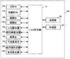
- FIG. 1is a schematic diagram showing an example of the configuration of the flying body system in the embodiment.
- Fig. 2is a diagram showing an example of a specific appearance of an unmanned aircraft.
- Fig. 3is a block diagram showing an example of the hardware configuration of the unmanned aircraft.
- Fig. 4is a block diagram showing an example of the hardware configuration of the terminal.
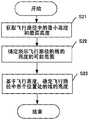
- FIG. 5is a flowchart showing an example of the operation of the unmanned aircraft when the flight path is displayed in the first display style.
- Fig. 6is a diagram showing a display example of a first flight path according to a first display style.
- FIG. 7is a diagram showing a display example of the second flight path according to the first display style.
- FIG. 8is a flowchart showing an example of the operation of the unmanned aircraft when the flight path is displayed in the second display style.
- FIG. 9is a diagram showing a display example of a third flight path according to a second display style.
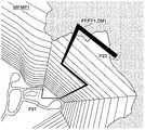
- Fig. 10is a diagram showing a display of a flight path in a comparative example.
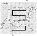
- FIG. 11is a diagram showing the display of the flight path in which the altitude information at the predetermined position of the flight path is supplemented with text in the comparative example.
- two-dimensional mapsCompared with three-dimensional maps, two-dimensional maps have more general maps and are easy to install, and the processing load of the flight path generation application is small.
- the viewpoint for displaying the three-dimensional mapneeds to be considered, and the rendering needs to be worked hard, while in the generation of the flight path using the two-dimensional map, these aspects need not be considered.
- a software or application for displaying a flight path(hereinafter, also referred to as a flight path display application) is used to display the flight path generated by the flight path generation application, and confirm to the user.
- the flight altitude in the flight path used for the flight in the flight rangeis mostly changed.
- the information representing the flight pathis a simple straight line at first glance, but the altitude may change sequentially.
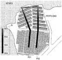
- FIG. 10is a diagram showing an example of the display of the flight path FPX superimposed on the two-dimensional map MPX in the comparative example.
- the flight path FPXis superimposed and displayed.
- the flight path FPXis the path used by the unmanned aircraft to investigate the cliff collapse site. Therefore, the flight path FPX has a height difference along at least the cliff in the map data.
- the flight path FPX with the height differenceis shown in the display style DMX.
- the flight path FPXis shown by a line of uniform thickness. Therefore, it is difficult to recognize which position in the flight path FPX has a high altitude and which position has a low altitude.
- FIG. 11is a diagram showing an example of the display of the flight path FPX superimposed on the two-dimensional map MPX in which the altitude information HI at the predetermined position of the flight path FPX in the comparative example is supplemented with text.
- the two-dimensional map MPX and the flight path FPX shown in FIG. 11are the same as the flight path in FIG. 10.
- the height information HI at the position PT where the flying direction in the flight path FPX is changedis represented by text information.
- the text informationis shown in the lead-out box corresponding to the position PT.
- the user who confirms the display of the flight path FPXcan recognize the altitude by confirming the text information.
- the flying objectis an unmanned aerial vehicle (UAV: Unmanned Aerial Vehicle) as an example.
- UAVUnmanned Aerial Vehicle
- the display control deviceis, for example, a terminal, or other devices (for example, unmanned aircraft, server, and other display control devices).
- the display control methoddefines the operation of the display control device.
- a programfor example, a program that causes the display control device to execute various processes is recorded in the recording medium.
- the “section” or “device” described in the following embodimentsis not limited to a physical structure realized by hardware, but also includes the realization of the function of the structure by software such as a program.
- the function of one structuremay be realized by two or more physical structures, or the function of two or more structures may also be realized by, for example, one physical structure.
- the “acquisition” described in the embodimentis not limited to the action of directly acquiring information or signals.
- a storage unitsuch as a memory, etc.
- FIG. 1is a schematic diagram showing a configuration example of a flying body system 10 in the embodiment.
- the flying body system 10includes an unmanned aircraft 100 and a terminal 80.
- the unmanned aircraft 100 and the terminal 80may communicate with each other through wired communication or wireless communication.
- the terminal 80is a portable terminal (for example, a smart phone, a tablet terminal), but it may also be another terminal (for example, a PC (Personal Computer, personal computer), which can control an unmanned aircraft through a joystick.
- 100 transmitterwireless proportional controller
- FIG. 2is a diagram showing an example of a specific appearance of unmanned aircraft 100. As shown in FIG. FIG. 2 shows a perspective view when the unmanned aircraft 100 is flying in the moving direction STV0. Unmanned aircraft 100 is an example of a moving body.
- the roll axis(refer to the x-axis) is provided in a direction parallel to the ground and along the moving direction STV0.
- set the pitch axis(refer to the y axis) in a direction parallel to the ground and perpendicular to the roll axis, and then set the yaw axis in the direction perpendicular to the ground and perpendicular to the roll axis and the pitch axis (refer to z axis).
- the unmanned aircraft 100is configured to include a UAV main body 102, a gimbal 200, an imaging unit 220, and a plurality of imaging units 230.
- the UAV main body 102includes a plurality of rotors (propellers).
- the UAV main body 102makes the unmanned aircraft 100 fly by controlling the rotation of a plurality of rotors.
- the UAV main body 102uses, for example, four rotors to fly the unmanned aircraft 100.
- the number of rotorsis not limited to four.
- the unmanned aircraft 100may be a fixed-wing aircraft without a rotor.
- the imaging unit 220is an imaging camera that captures a subject included in the expected imaging range (for example, the sky above the imaging target, the scenery such as mountains and rivers, and the buildings on the ground).
- the plurality of imaging units 230are sensor cameras that photograph the surroundings of the unmanned aircraft 100 in order to control the flight of the unmanned aircraft 100.
- the two camera units 230may be installed on the nose of the unmanned aircraft 100, that is, on the front side.
- the other two camera units 230may be provided on the bottom surface of the unmanned aircraft 100.
- the two imaging units 230 on the front sidemay be paired to function as a so-called stereo camera.
- the two imaging parts 230 on the bottom sidemay also be paired to function as a stereo camera.
- the three-dimensional space data around the unmanned aircraft 100may be generated based on the images captured by the plurality of imaging units 230.
- the number of imaging units 230 included in unmanned aircraft 100is not limited to four.
- the unmanned aircraft 100only needs to include at least one camera 230.
- the unmanned aircraft 100may include at least one camera 230 on the nose, tail, sides, bottom surface, and top surface of the unmanned aircraft 100, respectively.
- the angle of view that can be set in the camera section 230may be larger than the angle of view that can be set in the camera section 220.
- the imaging part 230may have a single focus lens or a fisheye lens.
- FIG. 3is a block diagram showing an example of the hardware configuration of unmanned aircraft 100.
- the unmanned aircraft 100is composed of a UAV control unit 110, a communication unit 150, a storage unit 160, a universal joint 200, a rotor mechanism 210, an imaging unit 220, an imaging unit 230, a GPS receiver 240, and an inertial measurement unit (IMU: Inertial Measurement Unit 250, magnetic compass 260, barometric altimeter 270, ultrasonic sensor 280, and laser measuring device 290.
- IMUInertial Measurement Unit 250
- magnetic compass 260magnetic compass 260
- barometric altimeter 270barometric altimeter 270
- ultrasonic sensor 280ultrasonic sensor
- the UAV control unit 110is composed of, for example, a CPU (Central Processing Unit: Central Processing Unit), MPU (Micro Processing Unit: Microprocessor), or DSP (Digital Signal Processor: Digital Signal Processor).
- the UAV control unit 110performs signal processing for overall control of the operations of each part of the unmanned aircraft 100, data input and output processing with other parts, data arithmetic processing, and data storage processing.
- the UAV control unit 110can control the flight of the unmanned aircraft 100 according to a program stored in the storage unit 160. In this case, the UAV control unit 110 can control the flight according to the set flight path. The UAV control unit 110 can control the flight according to an instruction from the control of the flight such as the manipulation of the terminal 80.
- the UAV control unit 110can capture images (for example, moving images, still images) (for example, aerial photography).
- the UAV control unit 110acquires position information indicating the position of the unmanned aircraft 100.
- the UAV control unit 110can obtain position information indicating the latitude, longitude, and altitude where the unmanned aircraft 100 is located from the GPS receiver 240.
- the UAV control unit 110can obtain the latitude and longitude information indicating the latitude and longitude of the unmanned aircraft 100 from the GPS receiver 240, and obtain the altitude information indicating the altitude of the unmanned aircraft 100 from the barometric altimeter 270 as position information.
- the UAV control unit 110may obtain the distance between the ultrasonic radiation point and the ultrasonic reflection point generated by the ultrasonic sensor 280 as height information.
- the UAV control unit 110can acquire the orientation information indicating the orientation of the unmanned aircraft 100 from the magnetic compass 260.
- the orientation informationmay be represented by, for example, an orientation corresponding to the orientation of the nose of the unmanned aircraft 100.
- the UAV control unit 110can acquire position information indicating the position where the unmanned aircraft 100 should exist when the imaging unit 220 captures the imaging range that should be captured.
- the UAV control unit 110may obtain position information indicating the position where the unmanned aircraft 100 should exist from the storage unit 160.
- the UAV control unit 110may obtain position information indicating the position where the unmanned aircraft 100 should exist from other devices through the communication unit 150.
- the UAV control unit 110may refer to a three-dimensional map database to specify the position where the unmanned aircraft 100 can exist, and obtain the position as position information indicating the position where the unmanned aircraft 100 should exist.
- the UAV control unit 110can acquire the respective imaging ranges of the imaging unit 220 and the imaging unit 230.
- the UAV control unit 110may acquire the angle of view information indicating the angle of view of the imaging unit 220 and the imaging unit 230 from the imaging unit 220 and the imaging unit 230 as a parameter for determining the imaging range.
- the UAV control unit 110may obtain information indicating the imaging direction of the imaging unit 220 and the imaging unit 230 as a parameter for determining the imaging range.
- the UAV control unit 110may obtain posture information indicating the posture state of the imaging unit 220 from the gimbal 200 as information indicating the imaging direction of the imaging unit 220, for example.
- the posture information of the imaging unit 220may indicate the angle of rotation of the universal joint 200 from the pitch axis and the yaw axis reference rotation angle.
- the UAV control unit 110may obtain position information indicating the location of the unmanned aircraft 100 as a parameter for determining the imaging range.
- the UAV control unit 110may limit the imaging range used to represent the geographic range captured by the imaging unit 220 according to the viewing angle and imaging direction of the imaging unit 220 and the imaging unit 230, and the location of the unmanned aircraft 100.
- the UAV control unit 110may obtain imaging range information from the storage unit 160.
- the UAV control unit 110may obtain imaging range information through the communication unit 150.
- the UAV control unit 110controls the universal joint 200, the rotor mechanism 210, the imaging unit 220, and the imaging unit 230.
- the UAV control unit 110can control the imaging range of the imaging unit 220 by changing the imaging direction or angle of view of the imaging unit 220.
- the UAV control unit 110can control the imaging range of the imaging unit 220 supported by the universal joint 200 by controlling the rotation mechanism of the universal joint 200.
- the imaging rangerefers to the geographic range captured by the imaging unit 220 or the imaging unit 230.
- the camera rangeis defined by latitude, longitude and altitude.
- the imaging rangemay be a range of three-dimensional spatial data defined by latitude, longitude, and altitude.
- the imaging rangemay be a range of two-dimensional spatial data defined by latitude and longitude.
- the imaging rangemay be determined based on the viewing angle and imaging direction of the imaging unit 220 or the imaging unit 230, and the location where the unmanned aircraft 100 is located.
- the imaging directions of the imaging unit 220 and the imaging unit 230may be defined by the orientation and depression angle of the imaging unit 220 and the imaging unit 230 on which the imaging lens is not installed.
- the imaging direction of the imaging unit 220may be a direction determined by the orientation of the nose of the unmanned aircraft 100 and the posture state of the imaging unit 220 with respect to the gimbal 200.
- the imaging direction of the imaging unit 230may be a direction determined from the orientation of the nose of the unmanned aircraft 100 and the position where the imaging unit 230 is installed.
- the UAV control unit 110can determine the surrounding environment of the unmanned aircraft 100 by analyzing multiple images captured by the multiple camera units 230.
- the UAV control unit 110may control the flight based on the surrounding environment of the unmanned aircraft 100, such as avoiding obstacles.
- the UAV control unit 110can acquire three-dimensional information (three-dimensional information) indicating the three-dimensional shape (three-dimensional shape) of an object existing around the unmanned aircraft 100.
- the objectmay be, for example, a part of a landscape such as buildings, roads, vehicles, and trees.
- the stereo informationis, for example, three-dimensional spatial data.
- the UAV control unit 110may generate 3D information indicating the 3D shape of an object existing around the unmanned aircraft 100 based on each image acquired by the plurality of camera units 230, thereby acquiring the 3D information.
- the UAV control unit 110can obtain the three-dimensional information representing the three-dimensional shape of the object existing around the unmanned aircraft 100 by referring to the three-dimensional map database stored in the storage unit 160.
- the UAV control unit 110can obtain three-dimensional information related to the three-dimensional shape of objects existing around the unmanned aircraft 100 by referring to a three-dimensional map database managed by a server existing on the network.
- the UAV control unit 110controls the flight of the unmanned aircraft 100 by controlling the rotor mechanism 210. That is, the UAV control unit 110 controls the position including the latitude, longitude, and altitude of the unmanned aircraft 100 by controlling the rotor mechanism 210.
- the UAV control unit 110can control the imaging range of the imaging unit 220 by controlling the flight of the unmanned aircraft 100.
- the UAV control unit 110can control the angle of view of the imaging unit 220 by controlling the zoom lens included in the imaging unit 220.
- the UAV control unit 110can use the digital zoom function of the camera unit 220 to control the angle of view of the camera unit 220 through digital zoom.
- the UAV control unit 110can move the unmanned aircraft 100 to a specific position on a specific date and time, so that the imaging unit 220 is at a desired position.
- the UAV control unit 110can move the unmanned aerial vehicle 100 to a specific position on a specific date and time to make the imaging unit 220 work as desired.
- the communication unit 150communicates with the terminal 80.
- the communication unit 150can perform wireless communication by any wireless communication method.
- the communication unit 150can perform wired communication through any wired communication method.
- the communication unit 150may send the captured image or additional information (metadata) related to the captured image to the terminal 80.
- the communication part 150may receive information about the flight path from the terminal 80.
- the storage unit 160can store various information, various data, various programs, and various images.
- the various imagesmay include a photographed image or an image based on the photographed image.
- the programmay include when the UAV control unit 110 controls the universal joint 200, the rotor mechanism 210, the imaging unit 220, the GPS receiver 240, the inertial measurement device 250, the magnetic compass 260, the barometric altimeter 270, the ultrasonic sensor 280, and the laser measuring device 290.
- the storage 160may be a computer-readable storage medium.
- the storage unit 160includes memory, which may include ROM (Read Only Memory), RAM (Random Access Memory, random access memory), and the like.
- the storage unit 160may include at least one of HDD (Hard Disk Drive), SSD (Solid State Drive), SD card, USB (Universal Serial bus, Universal Serial Bus) memory, and other memories. At least a part of the storage unit 160 can be detached from the unmanned aircraft 100.
- HDDHard Disk Drive
- SSDSolid State Drive
- SD cardSecure Digital Card
- USBUniversal Serial Bus
- USBUniversal Serial Bus
- the universal joint 200may rotatably support the imaging unit 220 around the yaw axis, the pitch axis, and the roll axis.
- the gimbal 200can change the imaging direction of the imaging unit 220 by rotating the imaging unit 220 around at least one of the yaw axis, the pitch axis, and the roll axis.
- the rotor mechanism 210has a plurality of rotor wings and a plurality of drive motors that rotate the plurality of rotor wings.
- the rotation of the rotor mechanism 210is controlled by the UAV control unit 110 to make the unmanned aircraft 100 fly.
- the imaging unit 220captures a subject in a desired imaging range and generates captured image data.
- the data of the captured image captured by the imaging unit 220may be stored in the memory included in the imaging unit 220 or the storage unit 160.
- the imaging unit 230captures the surroundings of the unmanned aircraft 100 and generates captured image data.
- the image data of the imaging unit 230may be stored in the storage unit 160.
- the GPS receiver 240receives a plurality of signals indicating the time transmitted from a plurality of navigation satellites (ie, GPS satellites) and the position (coordinate) of each GPS satellite.
- the GPS receiver 240calculates the position of the GPS receiver 240 (that is, the position of the unmanned aircraft 100) based on the received multiple signals.
- the GPS receiver 240outputs the position information of the unmanned aircraft 100 to the UAV control unit 110.
- the UAV control unit 110may replace the GPS receiver 240 to calculate the position information of the GPS receiver 240.
- the information indicating the time and the position of each GPS satellite included in the plurality of signals received by the GPS receiver 240is input to the UAV control unit 110.
- the inertial measurement device 250detects the posture of the unmanned aircraft 100 and outputs the detection result to the UAV control unit 110.
- the inertial measurement device 250can detect the acceleration in the front and rear, left and right, and up and down directions of the unmanned aircraft 100 and the angular velocities in the three axis directions of the pitch axis, the roll axis, and the yaw axis as the posture of the unmanned aircraft 100.
- the magnetic compass 260detects the orientation of the nose of the unmanned aircraft 100 and outputs the detection result to the UAV control unit 110.
- the barometric altimeter 270detects the flying altitude of the unmanned aircraft 100 and outputs the detection result to the UAV control unit 110.
- the ultrasonic sensor 280emits ultrasonic waves, detects ultrasonic waves reflected by the ground and objects, and outputs the detection result to the UAV control unit 110.
- the detection resultcan show the distance from the unmanned aircraft 100 to the ground, that is, the height.
- the detection resultcan show the distance from the unmanned aircraft 100 to the object (subject).
- the laser measuring instrument 290irradiates the object with laser light, receives the reflected light reflected by the object, and measures the distance between the unmanned aircraft 100 and the object (subject) through the reflected light.
- a time-of-flight methodmay be used.
- FIG. 4is a block diagram showing an example of the hardware configuration of the terminal 80.
- the terminal 80includes a terminal control unit 81, an operation unit 83, a communication unit 85, a storage unit 87, and a display unit 88.
- the terminal 80may be held by a user who desires to instruct the flight control of the unmanned aircraft 100.
- the terminal 80may instruct the flight control of the unmanned aircraft 100.
- the terminal control unit 81is configured using, for example, a CPU, MPU, or DSP.
- the terminal control unit 81performs signal processing for overall control of the operation of each part of the terminal 80, data input/output processing with other parts, data arithmetic processing, and data storage processing.
- the terminal control unit 81can acquire data or information from the unmanned aircraft 100 via the communication unit 85.
- the terminal control unit 81can also acquire data or information input via the operation unit 83.
- the terminal control unit 81may also obtain data or information stored in the storage unit 87.
- the terminal control unit 81can transmit data and information to the unmanned aircraft 100 via the communication unit 85.
- the terminal control unit 81may send data or information to the display unit 88 and cause the display unit 88 to display display information based on the data or information.
- the information displayed by the display unit 88 and sent to the unmanned aircraft 100 via the communication unit 85may include information about the flight path used for the unmanned aircraft 100 to fly, the imaging position, the captured image, and the image based on the captured image.
- the operation section 83receives and obtains data or information input by the user of the terminal 80.
- the operation unit 83may include input devices such as buttons, keys, a touch panel, and a microphone.
- the touch panelmay be composed of an operation unit 83 and a display unit 88. In this case, the operation section 83 can receive a touch operation, a click operation, a drag operation, and the like.
- the communication unit 85performs wireless communication with the unmanned aircraft 100 through various wireless communication methods.
- the wireless communication method of the wireless communicationmay include, for example, communication via a wireless LAN or a public wireless line.
- the communication unit 85can perform wired communication by any wired communication method.
- the storage unit 87can store various information, various data, various programs, and various images.
- the various programsmay include application programs executed by the terminal 80.
- the storage unit 87may be a computer-readable storage medium.
- the storage section 87may include ROM, RAM, and the like.
- the storage unit 87may include at least one of HDD, SSD, SD card, USB memory, and other memories. At least a part of the storage part 87 can be detached from the terminal 80.
- the storage unit 87may store a captured image acquired from the unmanned aircraft 100 or an image based on the captured image.
- the storage unit 87may store additional information of the captured image or the image based on the captured image.
- the display unit 88is configured by, for example, an LCD (Liquid Crystal Display), and displays various information or data output from the terminal control unit 81.
- the display section 88may display a captured image or an image based on the captured image.
- the display unit 88may also display various data and information related to the execution of the application program.
- the display part 88may display information about the flight path used for the unmanned aircraft 100 to fly. The flight path can be displayed by various display styles.
- the terminal control unit 81can perform processing related to display control of the flight path FP.
- the terminal control unit 81acquires information on the flight path FP.
- the flight path FPmay be the path of a single flight performed by the unmanned aircraft 100.
- the flight path FPmay be represented by a collection of multiple flight positions where the unmanned aircraft 100 flies.
- the flying positionhere can be a position in a three-dimensional space.
- the flight position informationmay include latitude, longitude, and altitude (flight altitude) information.
- the terminal control unit 81may generate the flight path FP by executing the flight path generation application, thereby obtaining the flight path FP.
- the terminal control unit 81can acquire the flight path FP from an external server or the like via the communication unit 85.
- the terminal control unit 81can acquire the flight path FP from the storage unit 87.
- the flight path FPcan be determined when setting the route.
- the terminal control unit 81may use the two-dimensional map MP to generate the flight path FP.
- the terminal control unit 81may obtain the two-dimensional map MP via the communication unit 85 or obtain it from the storage unit 87, or may generate the two-dimensional map MP based on a plurality of captured images obtained from the unmanned aircraft 100.
- the terminal control unit 81can specify through the operation unit 83 a plurality of two-dimensional positions where the unmanned aircraft 100 is flying on a two-dimensional plane indicated by the two-dimensional map MP and the height of each of the plurality of two-dimensional positions to determine Multiple flight positions of unmanned aircraft 100 in three-dimensional space.
- the terminal control unit 81can generate the flight path FP based on the determined flight positions (ie, the designated two-dimensional positions and heights).
- the terminal 80uses the two-dimensional map MP to generate the flight path FP, thereby facilitating the generation of the path and reducing the processing load in the terminal 80.
- a three-dimensional mapis used to generate a route
- the terminal control unit 81determines a display style for displaying the flight path FP.
- the display stylemay be a plurality of display styles as described later.
- the terminal control section 81may be configured to be displayed by at least one display style among a plurality of display styles.
- the terminal control unit 81can display the flight path FP on the display unit 88 in the determined display style.
- the terminal control unit 81may superimpose and display the flight path FP on the two-dimensional map MP.
- the terminal control unit 81can display the flight path FP so that the latitude and longitude of each position of the flight path FP coincide with the latitude and longitude of each position on the two-dimensional map MP.
- the usercan confirm the latitude and longitude of the flight path FP by confirming the display position of the flight path FP on the display unit 88. Furthermore, the user can confirm the height of the flight path FP by confirming the flight path FP displayed in the determined display style. Therefore, the terminal 80 can easily and intuitively recognize the height of the flight path of the flying object.
- the terminal control unit 81can transmit the information of the flight path FP to the unmanned aircraft 100 via the communication unit 85.
- the UAV control unit 110 of the unmanned aircraft 100can obtain the information of the flight path FP via the communication unit 150 and control the flight according to the flight path FP.
- the first display styleis a display style using the distance method.
- the two-dimensional map MPis generated from an image obtained by photographing the ground direction from above. Therefore, the higher the flying height, the larger or thicker the information indicating the flight path FP, and the lower the flying height, the smaller or thinner the information indicating the flight path FP.
- the terminal control unit 81by drawing (displaying) the flight path FP by the terminal control unit 81, the user can understand by converting the thickness W of the line representing the flight path FP into a distance relationship with the upper air as a starting point. That is, the user can understand that the flying height is higher at the position of the thicker part of the line representing the flight path FP; the flying height is lower at the position of the thinner part of the line representing the flight path FP.
- FIG. 5is a flowchart showing an example of the operation of the terminal 80 when the flight path FP is displayed in the first display style.
- the terminal control unit 81acquires a two-dimensional map MP (S11).
- the terminal control unit 81acquires the information of the flight path FP (S11).
- the terminal control unit 81acquires the lowest height Hmin among the flying heights H of each position of the flight path FP (S11).
- the terminal control unit 81determines the possible range of the thickness W of the line drawing the flight path FP (S12).
- the minimum value (the thinnest value) of the possible range of the line thickness Wis set to the minimum value Wmin, and the maximum value (the thickest value) is set to the maximum value Wmax.
- the possible range of the thickness W of the linehere can be determined according to the specifications of the terminal 80 and the executed application (for example, a flight path generation application or a flight path display application).
- the terminal control unit 81determines the thickness W of the line drawing the position of the flying height H in the flight path FP based on (Expression 1), for example (S13).
- ⁇can be any value, and the user can set it freely.
- the larger the ⁇the more significant the change in the thickness W of the drawn line. That is, the larger the ⁇ , the larger the amount of change in the change in the flying height H (Wmin ⁇ H/Hmin), and the larger the amount of change in the thickness W of the line relative to the change in the flying height H.
- the smaller the ⁇the smaller the change in the flying height H (Wmin ⁇ H/Hmin), and the smaller the change in the thickness W of the line relative to the change in the flying height H.
- the flying height Hmay be an absolute altitude (altitude) or a relative altitude.
- the relative altitudemay be the altitude at which the unmanned aircraft 100 flies relative to the lowest altitude of the ground.
- the lowest height of the ground corresponding to the flight path FPis 100 to 200 meters, and when flying at a height of 5 m relative to the ground, the relative height of the unmanned aircraft 100 to the ground is 5 m to 105 m.
- the absolute height of unmanned aircraft 100 at this timeis 105 m to 205 m.
- the terminal control unit 81can determine whether the flying height H is an absolute height or a relative height. For example, the terminal control unit 81 may obtain the user's operation information via the operation unit 83, and determine whether the flying height H is an absolute height or a relative height based on the operation information.
- the terminal 80adjusts the magnitude of ⁇ by the terminal control unit 81, and can appropriately adjust the amount of change in the thickness W of the line representing the flight path FP with respect to the change in the flying height H.
- Fig. 6is a diagram showing a display example of the flight path FP1 (first flight path) according to the display pattern DM1 (first display pattern).
- the flight path FP1is an example of the flight path FP.
- the flight path FP1is superimposed and displayed.
- the two-dimensional map MP1is an example of the two-dimensional map MP.
- the flight path FP1is a path used by the unmanned aircraft 100 to investigate the scene where the cliff collapsed. In the flight path FP1, along the cliff, the flight height H in the flight path FP1 greatly changes. The height of the unmanned aircraft 100 relative to the ground is maintained constant.
- the end point P11is located under the cliff, and since the flying height H is low, the line representing the flying path FP1 is thin.
- the end point P12is located on the cliff, and since the flying height H is high, the line representing the flight path FP1 is thick.
- the usercan easily understand the flying height H at each position on the flight path FP1 by confirming the thickness W of the line indicating the flight path FP1.
- the usercan easily control the unmanned aircraft 100 to fly along the cliff.
- FIG. 7is a diagram showing a display example of the flight path FP2 (second flight path) according to the display pattern DM1.
- the flight path FP2is an example of the flight path FP.
- the flight path FP2is superimposed and displayed.
- the two-dimensional map MP2is an example of the two-dimensional map MP.
- the flight path FP2is a path for investigating the periphery of the river RV flowing through the forest area.
- the flight height H in the flight path FP2greatly changes.
- the altitude of the part along the river RVis low, and the altitude becomes higher as it moves away from the river RV to both sides.
- the height of the unmanned aircraft 100 relative to the groundis maintained constant.
- the flying heightis higher than the flying height at the river RV, and the line representing the flying path FP2 is thicker.
- the flying height His lower than the surroundings like a valley bottom, and the line indicating the flight path FP2 is thin.
- the flight height H of the flight path FPdoes not change, indicating that the thickness W of the line of the flight path FP2 does not change.
- the usercan easily understand the flying height H at each position on the flight path FP2 by confirming the thickness W of the line indicating the flight path FP2.
- the usercan easily control the unmanned aircraft 100 to turn around the river RV and the river RV, and fly while changing directions.
- FIGS. 6 and 7exemplified the case where the height of the ground is a variable flying range, but even if the height of the ground is a fixed flying range, the flying height H of the flight path FP within the flying range changes. In this case, the thickness W of the line representing the flight path FP also changes. Furthermore, even if it is a cliff or a valley, regardless of the height of the ground, when the flying height H of the flying path FP is fixed, the thickness W of the line representing the flying path FP is also fixed.
- the line representing the flight path FPmay be superimposed and displayed on the two-dimensional map MP with transparency.
- the terminal 80can prevent the flight path FP from being superimposed and a part of the two-dimensional map MP being hidden and becoming unrecognizable. .
- the terminal 80controls the display of the flight path FP of the unmanned aircraft 100 (an example of the flying body).
- the terminal control section 81(an example of the processing section) of the terminal 80 can acquire a two-dimensional map MP including longitude and latitude.
- the terminal control unit 81can acquire the flight path FP of the unmanned aircraft 100 flying in the three-dimensional space.
- the terminal control unit 81may determine the display style of the flight path FP superimposed and displayed on the two-dimensional map MP based on the flight height H of the flight path FP (an example of the height).
- the terminal 80can intuitively understand the flight height H of the flight path FP by changing the display style of the information indicating the flight path FP, and only by viewing the display of the flight path FP.
- the display styleis combined with the flying height H of any place intact (refer to Fig. 11)
- the flight path FP in three-dimensional spaceis easier to understand.
- the terminal control unit 81can determine the thickness of the line representing the flight path superimposed and displayed on the two-dimensional map based on the height of the flight path FP. As a result, the flying height H of the flight path FP is reflected on the thickness W of the line representing the flight path FP. Therefore, the user can understand the change in the flying height H at each position of the flight path FP by confirming the thickness W of the line.
- Two-dimensional mapsare generated based on images taken from above the ground. Therefore, the state of the line representing the flight path FP has the same appearance as other imaging objects in the two-dimensional map FP. Therefore, the user can easily and intuitively understand the flying height H of the flying path FP displayed together with the two-dimensional map FP.
- the terminal control unit 81may adjust the amount of change in the thickness W of the change line of the flying height H with respect to the flight path FP.
- the terminal control unit 81can adjust the amount of change described above, for example, using the variable ⁇ in (Expression 1).
- the terminal 80can arbitrarily adjust the amount of change in the thickness W of the line.
- the flying height Hboth absolute height and relative height can be used, but regardless of which is used, the amount of change in the thickness W of the line of the flying height H with respect to the flight path FP can be appropriately adjusted.
- the terminal control unit 81can acquire the lowest height Hmin in the flight path FP, and acquire the possible range of the thickness W of the line.
- the possible range of the thickness W of the linecan be determined, for example, by the minimum value Wmin and the maximum value Wmax of the thickness.
- the terminal control unit 81can determine the thickness W of the line at each position in the flight path FP based on the lowest height Hmin and the possible range of the line thickness W.
- the terminal 80can determine the thickness W of the line according to the possible range of the thickness W of the line capable of displaying the flight path generation application or the flight path display application. Therefore, the user can observe the thickness W of the accurately displayed line, and accurately and intuitively confirm the flying height H of the flight path FP.
- the second display styleis a display style in which the color of the line drawing the flight path FP is changed according to the change in the height of the flight path FP.
- the color of the linemay be determined by at least one of hue, saturation, and brightness.
- the brightnesshere may be the brightness (Lightness) in the HLS color space, the brightness (Value) in the HSV color space, or the information representing the brightness in other color spaces.
- the brightness in the HLS color spaceis mainly used as an example.
- the hue of the colormay be changed according to the frequency of the spectrum of the color represented by visible light. In this case, the higher the flying height H, the closer to red, and the lower the flying height H, the closer the color is to purple.
- the brightness of the colormay be changed according to the amount of sunlight corresponding to the altitude. In this case, it can be set that the higher the flying height H, the brighter the color of the flight path FP (the greater the brightness), and the lower the flying height H, the darker the color of the flight path FP (the smaller the brightness).
- the terminal 80expresses the flying height H by using brightness, and can be set close to a change in brightness perceived by humans.
- the color of the linemay include the transparency of the line. That is, the terminal control unit 81 may change the transparency of the line based on the flying height H of the flying path FP.
- the terminal 80may indicate supplementary information AI, which indicates which color means which flying height H.
- the supplementary information AImay also be expressed on the two-dimensional map MP, and may also be expressed separately from the two-dimensional map MP.
- FIG. 8is a flowchart showing an example of the operation of the terminal 80 when the flight path FP is displayed in the second display style.
- the terminal control unit 81acquires a two-dimensional map MP (S21).
- the terminal control unit 81acquires the information of the flight path FP (S21).
- the terminal control unit 81acquires the lowest height Hmin and the highest height Hmax among the flying heights H at each position of the flight path FP (S21).
- the terminal control unit 81determines the possible range of the brightness L of the line drawing the flight path FP (S22).
- the minimum value (darkest value) of the possible range of the line brightness Lis set to the lowest brightness Lmin, and the maximum value (brightest value) is set to the highest brightness Lmax.
- the possible range of the brightness L of the linehere can be determined according to the specifications of the terminal 80, the executed application (for example, a flight path generation application or a flight path display application), and the like.
- the terminal control unit 81determines the brightness L of the line that draws the position of the flying height H in the flight path FP based on (Expression 2), for example (S23).
- the lowest brightness Lminis at the lowest altitude Hmin
- the highest brightness Lmaxis at the highest altitude Hmax
- the brightnesschanges in proportion to the change in the flying height H.
- the flying height Hmay be an absolute altitude (altitude) or a relative altitude.
- the terminal control unit 81can determine whether the flying height H is an absolute height or a relative height via the operation unit 83.
- FIG. 9is a diagram showing a display example of the flight path FP3 (third flight path) according to the display pattern DM2 (second display pattern).
- the flight path FP3is an example of the flight path FP.
- the flight path FP3is superimposed and displayed.
- the two-dimensional map MP3is an example of the two-dimensional map MP.
- the flight path FP3is used to investigate the path of the solar panel installed on the hillside.
- the flight height H of the flight path FP3changes along the hillside. The height of the unmanned aircraft 100 relative to the ground is maintained constant.
- the brightness L of the line representing the flight path FP3is low.
- the brightness L of the line representing the flight path FP3is high.
- the usercan easily understand the flying height H at each position on the flight path FP3 by confirming the brightness L of the line indicating the flight path FP3.
- the usercan easily control the flight of the unmanned aircraft 100 ascending and descending along the hillside.
- supplementary information AIis shown on the two-dimensional map MP3, and the supplementary information AI indicates which brightness L represents which flying height H.
- supplementary information AIa bar-shaped scale indicating the correspondence relationship between the flying height H and the brightness L is shown.
- the case where the height of the ground is a variable flying rangeis illustrated, but even if the height of the ground is a fixed flying range, when the flying height H of the flight path FP within the flying range changes, it shows The brightness of the line of the flight path FP also changes. Moreover, even if it is a cliff or a valley, regardless of the height of the ground, when the flying height H of the flying path FP is fixed, the brightness of the line representing the flying path FP is also fixed.
- the terminal control unit 81 of the terminal 80can determine the color of the line representing the flight path FP displayed superimposed on the two-dimensional map MP based on the flight height H of the flight path FP.
- the flying height H of the flying path FPis reflected in the color of the line representing the flying path FP. Therefore, the user can understand the change in the flying height H at each position of the flying path FP by confirming the color of the line.
- the terminal control section 81may determine the brightness L of the line (an example of the brightness).
- the flying height H of the flight path FPis reflected on the brightness L of the line representing the flight path FP. Therefore, the user can understand the change in the flying height H at each position of the flight path FP by checking the brightness L of the line.
- Two-dimensional mapsare generated based on images taken from the sky on the ground. Therefore, the state of the brightness L of the line representing the flight path FP as described above is the same as the state of the brightness L of the object irradiated by sunlight. Therefore, the user can easily and intuitively understand the flying height H of the flying path FP displayed together with the two-dimensional map MP.
- the terminal control unit 81may acquire the altitude range of the flight path FP.
- the altitude rangecan be determined by the lowest altitude Hmin and the highest altitude Hmax of the flight path FP.
- the terminal control unit 81can acquire the possible range of the brightness L of the line representing the flight path FP.
- the possible range of the line's brightness Lcan be determined by the lowest brightness Lmin and the highest brightness Lmax.
- the terminal control section 81may determine the brightness L of the line at each position in the flight path FP based on the height range and the possible range of the brightness L of the line.
- the terminal 80can determine the line brightness L according to the possible range of the line brightness L capable of displaying the flight path generation application or the flight path display application. Therefore, the user can accurately observe the brightness L of the displayed line, and accurately and intuitively confirm the flight height H of the flight path FP.
- the terminal control unit 81may display on the display unit 88 supplementary information AI indicating the correspondence between the flying height H of the flight path FP and the brightness L (an example of color) of the line indicating the flight path FP.
- the usercan easily recognize the flying height H in the flight path FP based on the brightness L by confirming the supplementary information AI.
- the terminal 80can easily understand the flight height H of the flight path FP by using the supplementary information AI.
- the terminal 80may also display the flight path FP in a display style that is a combination of the first display style and the second display style.
- the terminal control unit 81may adjust both the thickness W and the color of the line indicating the displayed flight path FP.
Landscapes
- Engineering & Computer Science (AREA)
- Radar, Positioning & Navigation (AREA)
- Remote Sensing (AREA)
- Physics & Mathematics (AREA)
- General Physics & Mathematics (AREA)
- Theoretical Computer Science (AREA)
- Aviation & Aerospace Engineering (AREA)
- Automation & Control Theory (AREA)
- General Engineering & Computer Science (AREA)
- Navigation (AREA)
- Processing Or Creating Images (AREA)
- Traffic Control Systems (AREA)
- Control Of Position, Course, Altitude, Or Attitude Of Moving Bodies (AREA)
Abstract
Description
Translated fromChinese本申请要求于2020-04-09递交的、申请号为JP2020-070330的日本专利申请的优先权,其内容一并在此作为参考。This application claims the priority of the Japanese patent application filed on 2020-04-09 with application number JP2020-070330, the content of which is incorporated herein by reference.
本公开涉及一种对用于飞行体飞行的飞行路径的显示进行控制的显示控制方法、显示控制装置、程序以及记录介质。The present disclosure relates to a display control method, a display control device, a program, and a recording medium for controlling the display of the flight path used for the flight of a flying body.
以往,已知有在包括经纬度信息的地图数据上显示飞行路径。例如,作为飞行路径,设置并显示使无人驾驶航空器按照地点D1、D2、D3的顺序飞行,最终回归到D1的飞行路径。Conventionally, it has been known to display the flight path on map data including latitude and longitude information. For example, as a flight path, set and display the unmanned aircraft to fly in the order of locations D1, D2, and D3, and finally return to the flight path of D1.
专利文献1:日本特开2017-222187号公报Patent Document 1: Japanese Patent Application Publication No. 2017-222187
发明内容Summary of the invention
在专利文献1中,在飞行路径的显示中,没有考虑飞行路径的各个位置处的高度。因此,对飞行路径的显示进行确认的用户难以直观地识别飞行路径的高度。In Patent Document 1, in the display of the flight path, the height at each position of the flight path is not considered. Therefore, it is difficult for a user who confirms the display of the flight path to intuitively recognize the height of the flight path.
在一个方面中,一种显示控制方法,其对飞行体的飞行路径的显示进行控制,其包括以下步骤:获取包括经度和纬度的信息的二维地图;获取在三维空间中的飞行体飞行的飞行路径;以及基于飞行路径的高度,确定二维地图上叠加显示的飞行路径的显示样式。In one aspect, a display control method, which controls the display of the flight path of a flying object, includes the following steps: acquiring a two-dimensional map including longitude and latitude information; and acquiring a flying object flying in a three-dimensional space Flight path; and based on the height of the flight path, determine the display style of the flight path superimposed and displayed on the two-dimensional map.
确定飞行路径的显示样式的步骤可以包括以下步骤:基于飞行路径的高度,确定表示二维地图上叠加显示的飞行路径的线的粗细。The step of determining the display style of the flight path may include the following steps: based on the height of the flight path, determining the thickness of the line representing the flight path superimposed and displayed on the two-dimensional map.
飞行路径的高度越高,表示飞行路径的线可以越粗;飞行路径的高度越低,表示飞行路径的线可以越细。The higher the height of the flight path, the thicker the line representing the flight path; the lower the height of the flight path, the thinner the line representing the flight path.
确定线的粗细的步骤可以包括以下步骤:调整相对于飞行路径的高度变化的线的粗细的变化量。The step of determining the thickness of the line may include the step of adjusting the amount of change in the thickness of the line with respect to the height change of the flight path.
确定线的粗细的步骤可以包括以下步骤:获取飞行路径上的最低高度;获取线的粗细的可能范围;以及基于最低高度和线的粗细的可能范围,确定飞行路径的各个位置处的线的粗细。The step of determining the thickness of the line may include the following steps: obtaining the lowest height on the flight path; obtaining the possible range of the line thickness; and determining the thickness of the line at each position of the flight path based on the lowest height and the possible range of the line thickness .
确定飞行路径的显示样式的步骤可以包括以下步骤:基于飞行路径的高度,确定表示二维地图上叠加显示的飞行路径的线的颜色。The step of determining the display style of the flight path may include the following steps: based on the height of the flight path, determining the color of the line representing the flight path superimposed and displayed on the two-dimensional map.
确定表示飞行路径的线的颜色的步骤可以包括以下步骤:确定线的亮度。The step of determining the color of the line representing the flight path may include the following step: determining the brightness of the line.
飞行路径的高度越高,线的亮度可以越高;飞行路径的高度越低,线的亮度可以越低。The higher the height of the flight path, the higher the brightness of the line; the lower the height of the flight path, the lower the brightness of the line.
确定线的亮度的步骤可以包括以下步骤:获取飞行路径的高度范围;获取线的亮度的可能范围;以及基于高度范围和线的亮度的可能范围,确定飞行路径的各个位置处的线的亮度。The step of determining the brightness of the line may include the following steps: obtaining the height range of the flight path; obtaining the possible range of the line brightness; and determining the brightness of the line at each position of the flight path based on the height range and the possible range of the line brightness.
获取飞行路径的步骤可以包括以下步骤:指定飞行体在二维地图所表示的二维平面飞行的多个二维位置;指定多个二维位置的各自的高度;以及基于指定的二维位置和高度,确定在三维空间中的飞行路径。The step of obtaining the flight path may include the following steps: designating a plurality of two-dimensional positions of the flying object flying on a two-dimensional plane represented by a two-dimensional map; designating the respective heights of the plurality of two-dimensional positions; and based on the designated two-dimensional position and Altitude, which determines the flight path in three-dimensional space.
显示控制方法还可以包括以下步骤:使所述飞行路径以确定的显示样式叠加于所述二维地图并显示在显示部上。The display control method may further include the step of superimposing the determined display style of the flight path on the two-dimensional map and displaying it on the display part.
确定飞行路径的显示样式的步骤可以包括以下步骤:基于飞行路径的高度,确定表示二维地图上叠加显示的飞行路径的线的颜色。叠加显示飞行路径的步骤可以包括以下步骤:显示表示飞行路径的高度与表示飞行路径的线的颜色的对应关系的补充信息。The step of determining the display style of the flight path may include the following steps: based on the height of the flight path, determining the color of the line representing the flight path superimposed and displayed on the two-dimensional map. The step of superimposing and displaying the flight path may include the following step: displaying supplementary information indicating the correspondence between the height of the flight path and the color of the line indicating the flight path.
在一个方面中,一种显示控制装置,其对用于飞行体飞行的飞行路径的显示进行控制,其包括处理部,处理部执行上述的显示控制方法中的任意一个。In one aspect, a display control device that controls the display of a flight path used for a flying object to fly includes a processing unit that executes any one of the above-mentioned display control methods.
在一个方面中,一种程序,其用于使控制用于飞行体飞行的飞行路径的显示的显示控制装置执行以下步骤:获取包括经度及纬度的二维地图;获取在三维空间中的飞行体飞行的飞行路径;以及基于飞行路径的高度,确定二维地图上叠加显示的飞行路径的显示样式。In one aspect, a program is used to make a display control device that controls the display of a flight path for a flying body to perform the following steps: acquiring a two-dimensional map including longitude and latitude; acquiring a flying body in a three-dimensional space The flight path of the flight; and based on the height of the flight path, determine the display style of the flight path superimposed and displayed on the two-dimensional map.
在一个方面中,一种记录介质,其为计算机可读记录介质,其记录有用于使控制用于飞行体飞行的飞行路径的显示的显示控制装置执行以下步骤的程序:获取包括经度和纬度的二维地图;获取在三维空间中的飞行体飞行的飞行路径;以及基于飞行路径的高度,确定在二维地图上叠加显示的飞行路径的显示样式。In one aspect, a recording medium, which is a computer-readable recording medium, is recorded with a program for causing a display control device that controls display of a flight path for flying of a flying object to perform the following steps: acquiring information including longitude and latitude A two-dimensional map; obtaining the flight path of the flying body in the three-dimensional space; and determining the display style of the flight path superimposed on the two-dimensional map based on the height of the flight path.
另外,上述发明的内容中并未穷举本公开的全部特征。此外,这些特征组的子组合也可以构成发明。In addition, the content of the above invention does not exhaust all the features of the present disclosure. In addition, sub-combinations of these feature groups can also constitute inventions.
图1是示出实施方式中的飞行体系统的构成示例的示意图。FIG. 1 is a schematic diagram showing an example of the configuration of the flying body system in the embodiment.
图2是示出无人驾驶航空器的具体外观的一个示例的图。Fig. 2 is a diagram showing an example of a specific appearance of an unmanned aircraft.
图3是示出无人驾驶航空器的硬件构成的一个示例的框图。Fig. 3 is a block diagram showing an example of the hardware configuration of the unmanned aircraft.
图4是示出终端的硬件构成的一个示例的框图。Fig. 4 is a block diagram showing an example of the hardware configuration of the terminal.
图5是示出由第一显示样式显示飞行路径时无人驾驶航空器的动作示例的流程图。FIG. 5 is a flowchart showing an example of the operation of the unmanned aircraft when the flight path is displayed in the first display style.
图6是示出根据第一显示样式的第一飞行路径的显示示例的图。Fig. 6 is a diagram showing a display example of a first flight path according to a first display style.
图7是示出根据第一显示样式的第二飞行路径的显示示例的图。FIG. 7 is a diagram showing a display example of the second flight path according to the first display style.
图8是示出由第二显示样式显示飞行路径时无人驾驶航空器的动作示例的流程图。FIG. 8 is a flowchart showing an example of the operation of the unmanned aircraft when the flight path is displayed in the second display style.
图9是示出根据第二显示样式的第三飞行路径的显示示例的图。FIG. 9 is a diagram showing a display example of a third flight path according to a second display style.
图10是示出比较例中的飞行路径的显示的图。Fig. 10 is a diagram showing a display of a flight path in a comparative example.
图11是示出比较例中用文字补充飞行路径的预定位置处的高度信息的飞行路径的显示的图。FIG. 11 is a diagram showing the display of the flight path in which the altitude information at the predetermined position of the flight path is supplemented with text in the comparative example.
以下,通过本发明的实施方式来对本公开进行说明,但是以下实施方式并非限制权利要求书所涉及的发明。实施方式中说明的特征的所有组合未必是发明的解决方案所必须的。Hereinafter, the present disclosure will be described through embodiments of the present invention, but the following embodiments do not limit the invention related to the claims. Not all the combinations of the features described in the embodiments are necessary for the solution of the invention.
权利要求书、说明书、说明书附图以及说明书摘要中包含作为著作权所保护对象的事项。任何人只要如专利局的文档或者记录所表示的那样进行这些文件的复制,著作权人则不会提出异议。但是,在除此以外的情况下,保留一切的著作权。The claims, the description, the drawings of the description, and the summary of the description include matters that are the subject of copyright protection. As long as anyone makes copies of these files as indicated in the patent office's documents or records, the copyright owner will not raise an objection. However, in other cases, all copyrights are reserved.
(实现本公开的一个方面的背景)(Background to realize one aspect of the present disclosure)
近年来,在利用无人驾驶航空器的各个领域,自动飞行的需求越来越高。为了预先计划无人驾驶航空器的自动飞行,需要有各领域专业知识的人员在地图数据上设计无人驾驶航空器的飞行路径。作为设计飞行路径时参照的地图,有包括纬度和经度的信息的二维地图,以及包括纬度、经度及高度的信息的三维地图。现状下,在用于生成飞行路径的软件或应用程序(以下,也简称为飞行路径生成应用)中,多采用在二维地图上计划飞行路径的方法。因为二维地图与三维地图相比,有较多通用地图,且容易安装,而且飞行路径生成应用的处理负荷小。另外,在使用三维地图的飞行路径的生成中,需要考虑用于显示三维地图的视点,并且需要在渲染上下功夫,而在使用二维地图的飞行路径的生成中,不需要考虑这些方面。In recent years, there has been an increasing demand for autonomous flight in various fields using unmanned aircraft. In order to plan the automatic flight of the unmanned aircraft in advance, personnel with expertise in various fields are required to design the flight path of the unmanned aircraft on the map data. As a map referenced when designing a flight path, there are two-dimensional maps that include information about latitude and longitude, and three-dimensional maps that include information about latitude, longitude, and altitude. Under the current situation, in software or application programs (hereinafter, also referred to as flight path generation applications) for generating flight paths, a method of planning a flight path on a two-dimensional map is often used. Compared with three-dimensional maps, two-dimensional maps have more general maps and are easy to install, and the processing load of the flight path generation application is small. In addition, in the generation of the flight path using the three-dimensional map, the viewpoint for displaying the three-dimensional map needs to be considered, and the rendering needs to be worked hard, while in the generation of the flight path using the two-dimensional map, these aspects need not be considered.
例如,使用用于显示飞行路径的软件或应用(以下,也简称为飞行路径显示应用)来显示由飞行路径生成应用生成的飞行路径,并向用户确认。For example, a software or application for displaying a flight path (hereinafter, also referred to as a flight path display application) is used to display the flight path generated by the flight path generation application, and confirm to the user.
在无人驾驶航空器飞行的飞行范围内的地面的海拔不同时,用于在飞行范围内飞行的 飞行路径中的飞行高度大多发生改变。然而,在现状的飞行路径显示应用中,难以识别飞行路径的高度变化。因此,难以把握飞行路径飞行时的飞行整体概况,难以把握飞行路径的正确性,并且难以区别纬度和经度相同的多个飞行路径。例如,表示飞行路径的信息乍看之下是简单的直线,然而高度可能依次变化。When the altitude of the ground in the flight range of the unmanned aircraft is different, the flight altitude in the flight path used for the flight in the flight range is mostly changed. However, in the current flight path display application, it is difficult to recognize the altitude change of the flight path. Therefore, it is difficult to grasp the overall flight profile during flight path flight, to grasp the accuracy of the flight path, and to distinguish multiple flight paths with the same latitude and longitude. For example, the information representing the flight path is a simple straight line at first glance, but the altitude may change sequentially.
图10是示出比较例中在二维地图MPX上叠加的飞行路径FPX的显示的一个示例的图。在图10所示的二维地图MPX中,飞行路径FPX被叠加显示。飞行路径FPX是用于由无人驾驶航空器调查悬崖塌陷现场的路径。因此,飞行路径FPX沿着地图数据中的至少悬崖的区域具有高低差。在图10中,具有高低差的飞行路径FPX以显示样式DMX示出。在显示样式DMX中,飞行路径FPX由均匀粗细的线示出。因此,难以识别飞行路径FPX中哪个位置的高度高、哪个位置的高度低。FIG. 10 is a diagram showing an example of the display of the flight path FPX superimposed on the two-dimensional map MPX in the comparative example. In the two-dimensional map MPX shown in FIG. 10, the flight path FPX is superimposed and displayed. The flight path FPX is the path used by the unmanned aircraft to investigate the cliff collapse site. Therefore, the flight path FPX has a height difference along at least the cliff in the map data. In FIG. 10, the flight path FPX with the height difference is shown in the display style DMX. In the display style DMX, the flight path FPX is shown by a line of uniform thickness. Therefore, it is difficult to recognize which position in the flight path FPX has a high altitude and which position has a low altitude.
图11是示出用文字补充了比较例中的飞行路径FPX的预定位置处的高度信息HI的、叠加在二维地图MPX上的飞行路径FPX的显示的一个示例的图。图11所示的二维地图MPX和飞行路径FPX与图10的飞行路径相同。在图11中,与图10相比,在变更飞行路径FPX中的飞行方向的位置PT处的高度信息HI用文字信息来表示。例如,文字信息在对应于该位置PT的引出框中示出。确认飞行路径FPX的显示的用户可以通过确认文字信息来识别高度。但即使在该情况下,也只能把握飞行路径FPX的一部分的高度,难以观察表示飞行路径FPX的线而进行直观地把握,以及难以把握考虑了高度的飞行路径FPX的整体概况。FIG. 11 is a diagram showing an example of the display of the flight path FPX superimposed on the two-dimensional map MPX in which the altitude information HI at the predetermined position of the flight path FPX in the comparative example is supplemented with text. The two-dimensional map MPX and the flight path FPX shown in FIG. 11 are the same as the flight path in FIG. 10. In FIG. 11, compared with FIG. 10, the height information HI at the position PT where the flying direction in the flight path FPX is changed is represented by text information. For example, the text information is shown in the lead-out box corresponding to the position PT. The user who confirms the display of the flight path FPX can recognize the altitude by confirming the text information. However, even in this case, only the height of a part of the flight path FPX can be grasped, it is difficult to observe the line indicating the flight path FPX and intuitively grasp it, and it is difficult to grasp the overall overview of the flight path FPX considering the altitude.
在以下实施方式中,对能够容易直观地识别飞行体飞行的飞行路径的高度的显示控制方法、显示控制装置、程序以及记录介质进行说明。In the following embodiments, a display control method, a display control device, a program, and a recording medium that can easily and intuitively recognize the height of the flight path of the flying object will be described.
在以下实施方式中,飞行体以无人驾驶航空器(UAV:Unmanned Aerial Vehicle)为例。显示控制装置例如为终端,也可以为其他装置(例如无人驾驶航空器、服务器以及其他显示控制装置)。显示控制方法规定了显示控制装置的动作。另外,记录介质中记录有程序(例如使显示控制装置执行各种处理的程序)。In the following embodiments, the flying object is an unmanned aerial vehicle (UAV: Unmanned Aerial Vehicle) as an example. The display control device is, for example, a terminal, or other devices (for example, unmanned aircraft, server, and other display control devices). The display control method defines the operation of the display control device. In addition, a program (for example, a program that causes the display control device to execute various processes) is recorded in the recording medium.
以下的实施方式中所述的“部”或者“装置”并不仅限于通过硬件实现的物理结构,也包括通过程序等软件实现该结构所具有的功能。另外,一个结构所具有的功能可以通过两个以上的物理结构实现,或者两个以上的结构的功能也可以通过例如一个物理结构实现。另外,实施方式中所述的“获取”并不仅限于表示直接获取信息或信号等的动作,例如除了处理部通过通信部进行获取即接收以外,也包括从存储部(例如存储器等)获取中的任一者。对于这些术语的理解和解释在权利要求书的记载中也相同。The “section” or “device” described in the following embodiments is not limited to a physical structure realized by hardware, but also includes the realization of the function of the structure by software such as a program. In addition, the function of one structure may be realized by two or more physical structures, or the function of two or more structures may also be realized by, for example, one physical structure. In addition, the “acquisition” described in the embodiment is not limited to the action of directly acquiring information or signals. For example, in addition to the acquisition or reception by the processing unit through the communication unit, it also includes the acquisition from a storage unit (such as a memory, etc.). Either. The understanding and interpretation of these terms are also the same in the description of the claims.
图1是示出实施方式中的飞行体系统10的构成示例的示意图。飞行体系统10包括无人驾驶航空器100及终端80。无人驾驶航空器100和终端80互相之间可以通过有线通信或无线通信进行通信。在图1中,例示了终端80是便携式终端(例如,智能手机、平板终端),但也可以是其他的终端(例如,PC(Personal Computer,个人计算机)、可通过控制杆操纵无人驾驶航空器100的发送器(无线比例控制器))。FIG. 1 is a schematic diagram showing a configuration example of a flying
图2是示出无人驾驶航空器100的具体外观的一个示例的图。图2示出了当无人驾驶航空器100沿移动方向STV0飞行时的立体图。无人驾驶航空器100为移动体的一个示例。FIG. 2 is a diagram showing an example of a specific appearance of
如图2所示,在与地面平行且沿着移动方向STV0的方向上设置滚转轴(参照x轴)。在此情况下,在与地面平行且与滚转轴垂直的方向上设置俯仰轴(参照y轴),进而,在与地面垂直且与滚转轴及俯仰轴垂直的方向上设置偏航轴(参照z轴)。As shown in FIG. 2, the roll axis (refer to the x-axis) is provided in a direction parallel to the ground and along the moving direction STV0. In this case, set the pitch axis (refer to the y axis) in a direction parallel to the ground and perpendicular to the roll axis, and then set the yaw axis in the direction perpendicular to the ground and perpendicular to the roll axis and the pitch axis (refer to z axis).
无人驾驶航空器100的构成为包括UAV主体102、万向节200、摄像部220以及多个摄像部230。The
UAV主体102包括多个旋翼(螺旋桨)。UAV主体102通过控制多个旋翼的旋转而使无人驾驶航空器100飞行。UAV主体102使用例如四个旋翼使无人驾驶航空器100飞行。旋翼的数量并不限于四个。此外,无人驾驶航空器100可以是没有旋翼的固定翼机。The UAV
摄像部220是对包括在预期摄像范围内的被摄体(例如,作为摄像对象的上空的情况、山川河流等景色、地上的建筑物)进行拍摄的拍摄用相机。The
多个摄像部230是为了控制无人驾驶航空器100的飞行而对无人驾驶航空器100的周围进行拍摄的传感用相机。两个摄像部230可以设置于无人驾驶航空器100的机头、即正面。并且,其他两个摄像部230可以设置于无人驾驶航空器100的底面。正面侧的两个摄像部230可以成对,起到所谓的立体相机的作用。底面侧的两个摄像部230也可以成对,起到立体相机的作用。可以基于由多个摄像部230拍摄到的图像来生成无人驾驶航空器100周围的三维空间数据。另外,无人驾驶航空器100所包括的摄像部230的数量不限于四个。无人驾驶航空器100只要包括至少一个摄像部230即可。无人驾驶航空器100可以在无人驾驶航空器100的机头、机尾、侧面、底面及顶面分别包括至少一个摄像部230。摄像部230中可设置的视角可大于摄像部220中可设置的视角。摄像部230可以具有单焦点镜头或鱼眼镜头。The plurality of
图3是示出无人驾驶航空器100的硬件构成的一个示例的框图。无人驾驶航空器100的构成为包括UAV控制部110、通信部150、存储部160、万向节200、旋翼机构210、摄像部220、摄像部230、GPS接收器240、惯性测量装置(IMU:Inertial Measurement Unit) 250、磁罗盘260、气压高度计270、超声波传感器280以及激光测定器290。FIG. 3 is a block diagram showing an example of the hardware configuration of
UAV控制部110例如由CPU(Central Processing Unit:中央处理器)、MPU(Micro Processing Unit:微处理器)或DSP(Digital Signal Processor:数字信号处理器)构成。UAV控制部110执行用于总体控制无人驾驶航空器100的各部分的动作的信号处理、与其它各部分之间的数据的输入输出处理、数据的运算处理以及数据的存储处理。The
UAV控制部110可以根据存储在存储部160中的程序对无人驾驶航空器100的飞行进行控制。在该情况下,UAV控制部110可以根据所设置的飞行路径控制飞行。UAV控制部110可以根据来自终端80的操纵等的飞行的控制的指示来控制飞行。UAV控制部110可以拍摄图像(例如动态图像、静止图像)(例如航拍)。The
UAV控制部110获取表示无人驾驶航空器100的位置的位置信息。UAV控制部110可以从GPS接收器240获取用于表示无人驾驶航空器100所在的纬度、经度以及高度的位置信息。UAV控制部110可以分别从GPS接收器240获取表示无人驾驶航空器100所在的纬度以及经度的纬度经度信息,并从气压高度计270获取表示无人驾驶航空器100所在的高度的高度信息,作为位置信息。UAV控制部110可以获取超声波传感器280产生的超声波放射点与超声波反射点之间的距离,作为高度信息。The
UAV控制部110可以从磁罗盘260获取表示无人驾驶航空器100的朝向的朝向信息。朝向信息可以用例如与无人驾驶航空器100的机头的朝向相对应的方位来表示。The
UAV控制部110可以获取表示在摄像部220对应该拍摄的摄像范围进行拍摄时无人驾驶航空器100所应该存在的位置的位置信息。UAV控制部110可以从存储部160获取表示无人驾驶航空器100应该存在的位置的位置信息。UAV控制部110可以通过通信部150从其他的装置获取表示无人驾驶航空器100应该存在的位置的位置信息。UAV控制部110可以参照三维地图数据库来指定无人驾驶航空器100所能够存在的位置,并获取该位置作为表示无人驾驶航空器100所应该存在的位置的位置信息。The
UAV控制部110可以获取摄像部220及摄像部230的各自的摄像范围。UAV控制部110可以从摄像部220和摄像部230获取用于表示摄像部220和摄像部230的视角的视角信息作为用于确定摄像范围的参数。UAV控制部110可以获取用于表示摄像部220和摄像部230的摄像方向的信息,作为用于确定摄像范围的参数。UAV控制部110可以从万向节200获取用于表示摄像部220的姿势状态的姿势信息,作为例如表示摄像部220的摄像方向的信息。摄像部220的姿势信息可以表示万向节200的从俯仰轴和偏航轴基准旋转角度旋转的角度。The
UAV控制部110可以获取用于表示无人驾驶航空器100所在位置的位置信息,作为用于确定摄像范围的参数。UAV控制部110可以根据摄像部220及摄像部230的视角及摄像方向以及无人驾驶航空器100所在位置,来限定用于表示摄像部220拍摄的地理范围的摄像范围。The
UAV控制部110可以从存储部160获取摄像范围信息。UAV控制部110可以通过通信部150获取摄像范围信息。The
UAV控制部110控制万向节200、旋翼机构210、摄像部220以及摄像部230。UAV控制部110可以通过变更摄像部220的摄像方向或视角来控制摄像部220的摄像范围。UAV控制部110可以通过控制万向节200的旋转机构来控制由万向节200所支持的摄像部220的摄像范围。The
摄像范围是指由摄像部220或摄像部230拍摄的地理范围。摄像范围由纬度、经度和高度定义。摄像范围可以是由纬度、经度和高度定义的三维空间数据的范围。摄像范围可以是由纬度和经度定义的二维空间数据的范围。摄像范围可以基于摄像部220或摄像部230的视角和摄像方向、以及无人驾驶航空器100所在的位置而确定。摄像部220和摄像部230的摄像方向可以由摄像部220和摄像部230的没置有摄像镜头的正面朝向的方位和俯角来定义。摄像部220的摄像方向可以是由无人驾驶航空器100的机头方位以及相对于万向节200的摄像部220的姿势状态而确定的方向。摄像部230的摄像方向可以是从无人驾驶航空器100的机头方位和设置有摄像部230的位置而确定的方向。The imaging range refers to the geographic range captured by the
UAV控制部110可以通过分析由多个摄像部230拍摄的多个图像,来确定无人驾驶航空器100的周围环境。UAV控制部110可以基于无人驾驶航空器100的周围环境,例如避开障碍物来控制飞行。The
UAV控制部110可以获取表示存在于无人驾驶航空器100周围的对象的立体形状(三维形状)的立体信息(三维信息)。对象例如可以是建筑物、道路、车辆、树木等风景的一部分。立体信息例如是三维空间数据。UAV控制部110可以根据由多个摄像部230获取的各个图像,生成表示存在于无人驾驶航空器100周围的对象的立体形状的立体信息,从而获取立体信息。UAV控制部110可以通过参照存储在存储部160中的三维地图数据库,来获取用于表示无人驾驶航空器100周围存在的对象的立体形状的立体信息。UAV控制部110可以通过参照由网络上存在的服务器所管理的三维地图数据库,来获取与存在于无人驾驶航空器100的周围的对象的立体形状相关的立体信息。The
UAV控制部110通过控制旋翼机构210来控制无人驾驶航空器100的飞行。即,UAV 控制部110通过控制旋翼机构210来对包含无人驾驶航空器100的纬度、经度以及高度的位置进行控制。UAV控制部110可以通过控制无人驾驶航空器100的飞行来控制摄像部220的摄像范围。UAV控制部110可以通过控制摄像部220所包括的变焦镜头来控制摄像部220的视角。UAV控制部110可以利用摄像部220的数字变焦功能,通过数字变焦来控制摄像部220的视角。The
当摄像部220固定于无人驾驶航空器100并且不能移动摄像部220时,UAV控制部110可以通过使无人驾驶航空器100在特定的日期时间移动到特定的位置,来使摄像部220在期望的环境下拍摄期望的摄像范围。或者,即使摄像部220不具有变焦功能并且不能变更摄像部220的视角,UAV控制部110也可以通过使无人驾驶航空器100在特定的日期时间移动到特定的位置,来使摄像部220在期望的环境下拍摄期望的摄像范围。When the
通信部150与终端80进行通信。通信部150可以通过任意的无线通信方式进行无线通信。通信部150可以通过任意的有线通信方式进行有线通信。通信部150可以将拍摄图像或拍摄图像的有关附加信息(元数据)发送给终端80。通信部150可以从终端80接收关于飞行路径的信息。The
存储部160可以存储各种信息、各种数据、各种程序、以及各种图像。各种图像可以包括拍摄图像或基于拍摄图像的图像。程序可以包括UAV控制部110对万向节200、旋翼机构210、摄像部220、GPS接收器240、惯性测量装置250、磁罗盘260、气压高度计270、超声波传感器280及激光测定器290进行控制时所需的程序。存储部160可以是计算机可读存储介质。存储部160包括存储器,可以包括ROM(Read Only Memory,只读存储器)、RAM(Random Access Memory,随机存取存储器)等。存储部160可以包括HDD(Hard Disk Drive,硬盘驱动器)、SSD(Solid State Drive,固态硬盘)、SD卡、USB(Universal Serial bus,通用串行总线)存储器、其他的存储器中的至少1个。存储部160的至少一部分可以从无人驾驶航空器100上拆卸下来。The
万向节200可以以偏航轴、俯仰轴以及滚转轴为中心可旋转地支持摄像部220。万向节200可以通过使摄像部220以偏航轴、俯仰轴以及滚转轴中的至少一个为中心旋转,来变更摄像部220的摄像方向。The
旋翼机构210具有多个旋翼和使多个旋翼旋转的多个驱动电机。旋翼机构210通过由UAV控制部110控制旋转,从而使无人驾驶航空器100飞行。The
摄像部220对期望的摄像范围中的被摄体进行拍摄并生成拍摄图像的数据。由摄像部220拍摄得到的拍摄图像的数据可以存储在摄像部220所具有的存储器或者存储部160中。The
摄像部230对无人驾驶航空器100的周围进行拍摄并生成拍摄图像的数据。摄像部230的图像数据可以存储在存储部160中。The
GPS接收器240接收表示从多个导航卫星(即GPS卫星)发送的时间以及各GPS卫星的位置(坐标)的多个信号。GPS接收器240根据接收到的多个信号,计算出GPS接收器240的位置(即无人驾驶航空器100的位置)。GPS接收器240将无人驾驶航空器100的位置信息输出到UAV控制部110。另外,可以由UAV控制部110代替GPS接收器240来进行GPS接收器240的位置信息的计算。在此情况下,GPS接收器240所接收到的多个信号中所包含的表示时间以及各GPS卫星的位置的信息被输入到UAV控制部110中。The
惯性测量装置250检测无人驾驶航空器100的姿势,并将检测结果输出到UAV控制部110。惯性测量装置250可以检测无人驾驶航空器100的前后、左右、以及上下三轴方向的加速度以及俯仰轴、滚转轴和偏航轴三轴方向的角速度,作为无人驾驶航空器100的姿势。The inertial measurement device 250 detects the posture of the
磁罗盘260检测无人驾驶航空器100的机头的方位,并将检测结果输出到UAV控制部110。The
气压高度计270检测无人驾驶航空器100的飞行高度,并将检测结果输出到UAV控制部110。The barometric altimeter 270 detects the flying altitude of the
超声波传感器280发射超声波,检测地面、物体反射的超声波,并将检测结果输出到UAV控制部110。检测结果可以示出从无人驾驶航空器100到地面的距离,即高度。检测结果可以示出从无人驾驶航空器100到物体(被摄体)的距离。The ultrasonic sensor 280 emits ultrasonic waves, detects ultrasonic waves reflected by the ground and objects, and outputs the detection result to the
激光测量仪290对物体照射激光,接收物体反射的反射光,并通过反射光来测量无人驾驶航空器100与物体(被摄体)之间的距离。作为基于激光的距离测量方法的一个示例,可以为飞行时间法。The laser measuring instrument 290 irradiates the object with laser light, receives the reflected light reflected by the object, and measures the distance between the
图4是示出终端80的硬件构成的一个示例的框图。终端80包括终端控制部81、操作部83、通信部85、存储部87及显示部88。终端80可以由期望指示无人驾驶航空器100的飞行控制的用户所持有。终端80可以指示无人驾驶航空器100的飞行控制。FIG. 4 is a block diagram showing an example of the hardware configuration of the terminal 80. The terminal 80 includes a
终端控制部81例如采用CPU、MPU或DSP构成。终端控制部81进行用于整体控制终端80的各部分动作的信号处理、与其他各部分之间的数据的输入输出处理、数据的运算处理以及数据的存储处理。The
终端控制部81可以经由通信部85获取来自无人驾驶航空器100的数据或信息。终端控制部81也可以获取经由操作部83输入的数据或信息。终端控制部81也可以获取存储 在存储部87的数据或信息。终端控制部81可以经由通信部85向无人驾驶航空器100发送数据、信息。终端控制部81也可以将数据或信息发送到显示部88,并使显示部88显示基于数据或信息的显示信息。显示部88所显示的信息经由通信部85向无人驾驶航空器100发送的信息可以包括:用于无人驾驶航空器100飞行的飞行路径、摄像位置、拍摄图像以及基于拍摄图像的图像的信息。The
操作部83接收并获取由终端80的用户输入的数据或信息。操作部83可以包括按钮、按键、触摸面板、麦克风等输入装置。触摸面板可以由操作部83与显示部88构成。在这种情况下,操作部83可以接收触摸操作、点击操作、拖动操作等。The
通信部85通过各种无线通信方式与无人驾驶航空器100之间进行无线通信。例如,该无线通信的无线通信方式可以包括例如经由无线LAN或公共无线线路的通信。通信部85可以通过任意的有线通信方式进行有线通信。The
存储部87可以存储各种信息、各种数据、各种程序、以及各种图像。各种程序可以包括由终端80执行的应用程序。存储部87可以是计算机可读存储介质。存储部87可以包括ROM、RAM等。存储部87可以包括HDD、SSD、SD卡、USB存储器、其他的存储器中的至少1个。存储部87的至少一部分可以从终端80上拆卸下来。The
存储部87可以对从无人驾驶航空器100获取的拍摄图像或基于拍摄图像的图像进行存储。存储部87可以对拍摄图像或基于拍摄图像的图像的附加信息进行存储。The
显示部88例如采用LCD(Liquid Crystal Display,液晶显示器)构成,显示从终端控制部81输出的各种信息或数据。例如,显示部88可以显示拍摄图像或基于拍摄图像的图像。显示部88也可以显示涉及应用程序的执行的各种数据和信息。显示部88可以显示关于用于无人驾驶航空器100飞行的飞行路径的信息。飞行路径可以由各种显示样式显示。The
接下来对飞行路径的显示控制进行详细的说明。Next, the display control of the flight path will be described in detail.
终端控制部81可以进行对飞行路径FP的显示控制的相关处理。终端控制部81获取飞行路径FP的信息。飞行路径FP可以是无人驾驶航空器100进行的单次飞行的路径。飞行路径FP可以由无人驾驶航空器100飞行的多个飞行位置的集合来表示。此处的飞行位置可以是三维空间中的位置。飞行位置的信息可以包括纬度、经度以及高度(飞行高度)的信息。The
终端控制部81可以通过执行飞行路径生成应用来生成飞行路径FP,从而获取飞行路径FP。终端控制部81可以经由通信部85从外部服务器等获取飞行路径FP。终端控制部81可以从存储部87获取飞行路径FP。飞行路径FP可以在设置路线时确定。The
终端控制部81可以采用二维地图MP来生成飞行路径FP。终端控制部81可以经由通信部85获取二维地图MP,或者从存储部87获取,也可以根据从无人驾驶航空器100获取的多个拍摄图像来生成二维地图MP。例如,终端控制部81可以经由操作部83指定无人驾驶航空器100在二维地图MP所表示的二维平面上飞行的多个二维位置以及多个二维位置的各个位置的高度,来确定在三维空间中无人驾驶航空器100飞行的多个飞行位置。终端控制部81可以通过所确定的多个飞行位置(即指定的多个二维位置和高度)地生成飞行路径FP。The
终端80使用二维地图MP生成飞行路径FP,从而便于生成路径,并且能够减少终端80中的处理负荷。此外,与使用三维地图来生成路径的情况相比,不需要确定用于确定作为显示对象的三维空间的区域的视点或视线,并且终端80能够减轻用户的工作量。因此,生成飞行路径FP的用户即使不是进行例如游戏设计之类的复杂路径设计的用户,也可以简单地生成路径。The terminal 80 uses the two-dimensional map MP to generate the flight path FP, thereby facilitating the generation of the path and reducing the processing load in the terminal 80. In addition, compared with the case where a three-dimensional map is used to generate a route, there is no need to determine a viewpoint or line of sight for determining an area of a three-dimensional space as a display object, and the terminal 80 can reduce the workload of the user. Therefore, even if the user who generates the flight path FP is not a user who performs complicated path design such as game design, the path can be easily generated.
终端控制部81确定用于显示飞行路径FP的显示样式。显示样式如后述所述,可以是多个显示样式。终端控制部81可以设置成由多个显示样式中的至少一个显示样式来显示。终端控制部81可以以所确定的显示样式,使飞行路径FP显示在显示部88。终端控制部81可以在二维地图MP上叠加显示飞行路径FP。终端控制部81可以使飞行路径FP的各位置的纬度和经度与二维地图MP中各位置的纬度和经度一致地显示飞行路径FP。The
由此,与飞行路径FP的显示样式无关地,用户能够通过确认显示部88上的飞行路径FP的显示位置,来确认飞行路径FP的纬度及经度。而且,用户能够通过确认以所确定的显示样式显示的飞行路径FP来确认飞行路径FP的高度。因此,终端80能够容易直观地识别出飞行体飞行的飞行路径的高度。Thus, regardless of the display style of the flight path FP, the user can confirm the latitude and longitude of the flight path FP by confirming the display position of the flight path FP on the
终端控制部81可以经由通信部85将飞行路径FP的信息发送到无人驾驶航空器100。无人驾驶航空器100的UAV控制部110可以经由通信部150获取飞行路径FP的信息,并按照飞行路径FP控制飞行。The
接下来对飞行路径FP的第一显示样式进行说明。Next, the first display style of the flight path FP will be described.
第一显示样式是利用远近法的显示样式。例如,二维地图MP根据从上空拍摄地面方向而得到的图像生成。因此,飞行高度越高,表示飞行路径FP的信息可以设为越大或越粗,而飞行高度越低,表示飞行路径FP的信息可以设为越小或越细。这样,通过终端控制部81绘制(显示)飞行路径FP,用户能够将表示飞行路径FP的线的粗细W转换为以上空为起点的远近关系来得以理解。即,用户能够理解:在表示飞行路径FP的线的较粗 部分的位置,飞行高度较高;在表示飞行路径FP的线的较细部分的位置,飞行高度较低。The first display style is a display style using the distance method. For example, the two-dimensional map MP is generated from an image obtained by photographing the ground direction from above. Therefore, the higher the flying height, the larger or thicker the information indicating the flight path FP, and the lower the flying height, the smaller or thinner the information indicating the flight path FP. In this way, by drawing (displaying) the flight path FP by the
图5是示出由第一显示样式显示飞行路径FP时终端80的动作示例的流程图。FIG. 5 is a flowchart showing an example of the operation of the terminal 80 when the flight path FP is displayed in the first display style.
终端控制部81获取二维地图MP(S11)。终端控制部81获取飞行路径FP的信息(S11)。终端控制部81获取飞行路径FP的各位置的飞行高度H中的最低高度Hmin(S11)。The
终端控制部81确定绘制飞行路径FP的线的粗细W的可能范围(S12)。将线的粗细W的可能范围的最小值(最细值)设为最小值Wmin,将最大值(最粗值)设为最大值Wmax。此处的线的粗细W的可能范围可以根据终端80的规格、执行的应用(例如飞行路径生成应用或者飞行路径显示应用)等来确定。The
终端控制部81根据例如(式1)来确定绘制飞行路径FP中的飞行高度H的位置的线的粗细W(S13)。The
(式1)(Formula 1)

在(式1)中,ε可以是任意值,用户可以自由设置。ε越大,绘制的线的粗细W的变化越显著。即,ε越大,飞行高度H的变化(Wmin×ε×H/Hmin)的变化量越大,从而相对于飞行高度H的变化的线的粗细W的变化量越大。反之,ε越小,飞行高度H的变化(Wmin×ε×H/Hmin)的变化量越小,从而相对于飞行高度H的变化的线的粗细W的变化量越小。In (Equation 1), ε can be any value, and the user can set it freely. The larger the ε, the more significant the change in the thickness W of the drawn line. That is, the larger the ε, the larger the amount of change in the change in the flying height H (Wmin×ε×H/Hmin), and the larger the amount of change in the thickness W of the line relative to the change in the flying height H. Conversely, the smaller the ε, the smaller the change in the flying height H (Wmin×ε×H/Hmin), and the smaller the change in the thickness W of the line relative to the change in the flying height H.
飞行高度H可以是绝对高度(海拔),也可以是相对高度。例如,将与飞行路径FP对应的地面的最低高度设为0,相对高度可以是无人驾驶航空器100相对于地面的最低高度飞行的高度。例如,与飞行路径FP对应的地面的最低高度为100~200米,当维持在相对于地面5m的高度下飞行时,无人驾驶航空器100相对于地面的相对高度为5m~105m。另一方面,此时的无人驾驶航空器100的绝对高度为105m~205m。The flying height H may be an absolute altitude (altitude) or a relative altitude. For example, if the lowest altitude of the ground corresponding to the flight path FP is set to 0, the relative altitude may be the altitude at which the
终端控制部81可以确定飞行高度H是绝对高度还是相对高度。例如,终端控制部81可以经由操作部83获取用户的操作信息,根据操作信息来确定飞行高度H是绝对高度还是相对高度。The
在上述示例中,由于相对高度比绝对高度小,因此相对于飞行高度H的变化的线的粗细W的变化量变大。即使在该情况下,终端80通过终端控制部81调整ε的大小,也能够适当地调整表示相对于飞行高度H的变化的飞行路径FP的线的粗细W的变化量。In the above example, since the relative height is smaller than the absolute height, the amount of change in the thickness W of the line with respect to the change in the flying height H becomes larger. Even in this case, the terminal 80 adjusts the magnitude of ε by the
图6是表示根据显示样式DM1(第一显示样式)的飞行路径FP1(第一飞行路径)的 显示示例的图。飞行路径FP1是飞行路径FP的一个示例。在图6所示的二维地图MP1中,飞行路径FP1被叠加显示。二维地图MP1是二维地图MP的一个示例。飞行路径FP1是用于由无人驾驶航空器100调查悬崖塌陷的现场的路径。在飞行路径FP1中,沿着悬崖,飞行路径FP1中的飞行高度H大幅变化。无人驾驶航空器100相对于地面的高度维持为固定。Fig. 6 is a diagram showing a display example of the flight path FP1 (first flight path) according to the display pattern DM1 (first display pattern). The flight path FP1 is an example of the flight path FP. In the two-dimensional map MP1 shown in FIG. 6, the flight path FP1 is superimposed and displayed. The two-dimensional map MP1 is an example of the two-dimensional map MP. The flight path FP1 is a path used by the
在图6所示的显示样式DM1中,端点P11侧位于悬崖下,由于飞行高度H低,所以表示飞行路径FP1的线较细。端点P12侧位于悬崖上,由于飞行高度H高,所以表示飞行路径FP1的线较粗。用户通过确认表示飞行路径FP1的线的粗细W,能够容易地理解飞行路径FP1上的各位置处的飞行高度H。并且,作为飞行路径FP1的飞行的整体概况,用户能够容易地掌控无人驾驶航空器100沿着悬崖飞行。In the display pattern DM1 shown in FIG. 6, the end point P11 is located under the cliff, and since the flying height H is low, the line representing the flying path FP1 is thin. The end point P12 is located on the cliff, and since the flying height H is high, the line representing the flight path FP1 is thick. The user can easily understand the flying height H at each position on the flight path FP1 by confirming the thickness W of the line indicating the flight path FP1. And, as an overall overview of the flight of the flight path FP1, the user can easily control the
图7是表示根据显示样式DM1的飞行路径FP2(第二飞行路径)的显示示例的图。飞行路径FP2是飞行路径FP的一个示例。在图7所示的二维地图MP2中,飞行路径FP2被叠加显示。二维地图MP2是二维地图MP的一个示例。飞行路径FP2是用于调查流经山林地带的河流RV的周边的路径。在飞行路径FP2中,沿着河流RV的周边,飞行路径FP2中的飞行高度H大幅变化。在图7所示的地带中,沿着河流RV的部分的海拔低,随着从河流RV向两侧远离,海拔变高。无人驾驶航空器100相对于地面的高度维持为固定。FIG. 7 is a diagram showing a display example of the flight path FP2 (second flight path) according to the display pattern DM1. The flight path FP2 is an example of the flight path FP. In the two-dimensional map MP2 shown in FIG. 7, the flight path FP2 is superimposed and displayed. The two-dimensional map MP2 is an example of the two-dimensional map MP. The flight path FP2 is a path for investigating the periphery of the river RV flowing through the forest area. In the flight path FP2, along the periphery of the river RV, the flight height H in the flight path FP2 greatly changes. In the zone shown in FIG. 7, the altitude of the part along the river RV is low, and the altitude becomes higher as it moves away from the river RV to both sides. The height of the
在图7所示的显示样式DM1中,在端点P21侧和端点P22侧,飞行高度比河流RV处的飞行高度高,表示飞行路径FP2的线较粗。另一方面,在端点P21和端点P22的中央附近的位置(河流RV对应的位置),飞行高度H如谷底那样,与周围相比较低,表示飞行路径FP2的线较细。另外,在飞行路径FP2中与河流RV平行移动的部分,飞行路径FP的飞行高度H没有变化,表示飞行路径FP2的线的粗细W没有变化。用户通过确认表示飞行路径FP2的线的粗细W,能够容易地理解飞行路径FP2上的各位置处的飞行高度H。并且,作为飞行路径FP2的飞行的整体概况,用户能够容易地掌控无人驾驶航空器100在河流RV以及河流RV的周边转弯,一边转换方向一边飞行。In the display pattern DM1 shown in FIG. 7, on the end point P21 side and the end point P22 side, the flying height is higher than the flying height at the river RV, and the line representing the flying path FP2 is thicker. On the other hand, at the positions near the center of the endpoint P21 and the endpoint P22 (the position corresponding to the river RV), the flying height H is lower than the surroundings like a valley bottom, and the line indicating the flight path FP2 is thin. In addition, in the portion of the flight path FP2 that moves parallel to the river RV, the flight height H of the flight path FP does not change, indicating that the thickness W of the line of the flight path FP2 does not change. The user can easily understand the flying height H at each position on the flight path FP2 by confirming the thickness W of the line indicating the flight path FP2. In addition, as an overall overview of the flight of the flight path FP2, the user can easily control the
另外,在图6和图7中,例示了地面的高度是变化的飞行范围的情况,但即使是地面的高度是固定的飞行范围,在飞行范围内的飞行路径FP的飞行高度H发生变化的情况下,表示飞行路径FP的线的粗细W也发生变化。而且,即使是悬崖或山谷,与地面的高度无关地,在飞行路径FP的飞行高度H固定的情况下,表示飞行路径FP的线的粗细W也固定。In addition, in FIGS. 6 and 7 exemplified the case where the height of the ground is a variable flying range, but even if the height of the ground is a fixed flying range, the flying height H of the flight path FP within the flying range changes. In this case, the thickness W of the line representing the flight path FP also changes. Furthermore, even if it is a cliff or a valley, regardless of the height of the ground, when the flying height H of the flying path FP is fixed, the thickness W of the line representing the flying path FP is also fixed.
此外,虽然例示了表示飞行路径FP的线无透明性地在二维地图MP上叠加显示的情 况,但表示飞行路径FP的线可以具有透明性地在二维地图MP上叠加显示。例如,通过终端控制部81在半透明的状态下在二维地图MP上叠加显示飞行路径FP,终端80能够抑制飞行路径FP被叠加而二维地图MP的一部分被隐藏而变得不能辨认的情况。In addition, although the case where the line representing the flight path FP is superimposed and displayed on the two-dimensional map MP without transparency is exemplified, the line representing the flight path FP may be superimposed and displayed on the two-dimensional map MP with transparency. For example, by superimposing and displaying the flight path FP on the two-dimensional map MP in a semi-transparent state by the
由此,终端80(显示控制装置的一个示例)控制无人驾驶航空器100(飞行体的一个示例)的飞行路径FP的显示。终端80的终端控制部81(处理部的一个示例)可以获取包括经度和纬度的二维地图MP。终端控制部81可以获取在三维空间中的无人驾驶航空器100飞行的飞行路径FP。终端控制部81可以基于飞行路径FP的飞行高度H(高度的一个示例),确定在二维地图MP上叠加显示的飞行路径FP的显示样式。Thus, the terminal 80 (an example of the display control device) controls the display of the flight path FP of the unmanned aircraft 100 (an example of the flying body). The terminal control section 81 (an example of the processing section) of the terminal 80 can acquire a two-dimensional map MP including longitude and latitude. The
由此,终端80通过改变表示飞行路径FP的信息的显示样式,仅查看飞行路径FP的显示,就能够直观地理解飞行路径FP的飞行高度H。与显示样式原封不动地结合任意地点的飞行高度H显示的情况(参照图11)相比,不需要单独使用高度信息,在清楚确认二维地图MP的同时,容易直观地理解飞行路径FP,并且在三维空间中飞行路径FP更易了解。Thus, the terminal 80 can intuitively understand the flight height H of the flight path FP by changing the display style of the information indicating the flight path FP, and only by viewing the display of the flight path FP. Compared with the case where the display style is combined with the flying height H of any place intact (refer to Fig. 11), there is no need to use the height information alone. It is easy to intuitively understand the flight path FP while clearly confirming the two-dimensional map MP. And the flight path FP in three-dimensional space is easier to understand.
而且,终端控制部81基于飞行路径FP的高度可以确定表示二维地图上叠加显示的飞行路径的线的粗细。由此,飞行路径FP的飞行高度H反映在表示飞行路径FP的线的粗细W上,因此用户通过确认线的粗细W,能够理解飞行路径FP的各位置处的飞行高度H的变化。Furthermore, the
而且,飞行路径FP的高度H越高,表示飞行路径FP的线可以越粗,飞行路径FP的高度越低,表示飞行路径FP的线可以越细。二维地图是基于从上空对地面进行拍摄而得到的图像生成的。因此,表示飞行路径FP的线的状态与二维地图FP中的其他摄像对象具有同样的外观。所以,用户容易直观地理解与二维地图FP一起显示的飞行路径FP的飞行高度H。Moreover, the higher the height H of the flight path FP, the thicker the line representing the flight path FP, and the lower the height of the flight path FP, the thinner the line representing the flight path FP. Two-dimensional maps are generated based on images taken from above the ground. Therefore, the state of the line representing the flight path FP has the same appearance as other imaging objects in the two-dimensional map FP. Therefore, the user can easily and intuitively understand the flying height H of the flying path FP displayed together with the two-dimensional map FP.
另外,终端控制部81也可以调整相对于飞行路径FP的飞行高度H的变化线的粗细W的变化量。终端控制部81例如可以使用(式1)中的变量ε来调整上述变化量。由此,终端80能够任意调整线的粗细W的变化量。而且,作为飞行高度H,绝对高度和相对高度均可以使用,但是无论使用哪个,都能够适当地调整相对于飞行路径FP的飞行高度H的线的粗细W的变化量。In addition, the
另外,终端控制部81可以获取飞行路径FP中的最低高度Hmin,以及获取线的粗细W的可能范围。线的粗细W的可能范围可以例如由粗细的最小值Wmin和最大值Wmax来确定。终端控制部81基于最低高度Hmin和线的粗细W的可能范围,可以确定飞行路 径FP中各个位置处的线的粗细W。由此,例如,终端80可以根据能够显示飞行路径生成应用或飞行路径显示应用的线的粗细W的可能范围来确定线的粗细W。因此,用户能够观察准确地显示的线的粗细W,准确直观地确认飞行路径FP的飞行高度H。In addition, the
首先,对飞行路径FP的第二显示样式进行说明。First, the second display style of the flight path FP will be described.
第二显示样式是根据飞行路径FP的高度变化来改变绘制飞行路径FP的线的颜色的显示样式。线的颜色可以由色相(Hue)、色饱和度(Saturation)和亮度中的至少一个来确定。此处的亮度可以是HLS颜色空间中的亮度(Lightness),也可以是HSV颜色空间中的亮度(Value),还可以是表示其他颜色空间中的亮度的信息。在本实施方式中,主要以HLS颜色空间中的亮度作为亮度为例。另外,也可以只考虑灰度中亮度的变化。The second display style is a display style in which the color of the line drawing the flight path FP is changed according to the change in the height of the flight path FP. The color of the line may be determined by at least one of hue, saturation, and brightness. The brightness here may be the brightness (Lightness) in the HLS color space, the brightness (Value) in the HSV color space, or the information representing the brightness in other color spaces. In this embodiment, the brightness in the HLS color space is mainly used as an example. In addition, it is also possible to consider only the change in brightness in the grayscale.
例如,作为绘制飞行路径FP的线的颜色,颜色的色相也可以根据可见光所表示的颜色的光谱的频率而变化。在此情况下,可以飞行高度H越高,越接近红色,飞行高度H越低,颜色越接近紫色。另外,作为绘制飞行路径FP的线的颜色,颜色的亮度可以根据与海拔对应的日照量而变化。在此情况下,可以设为飞行高度H越高,表示飞行路径FP的颜色就越亮(亮度越大),飞行高度H越低,表示飞行路径FP的颜色就越暗(亮度越小)。For example, as the color of the line drawing the flight path FP, the hue of the color may be changed according to the frequency of the spectrum of the color represented by visible light. In this case, the higher the flying height H, the closer to red, and the lower the flying height H, the closer the color is to purple. In addition, as the color of the line drawing the flight path FP, the brightness of the color may be changed according to the amount of sunlight corresponding to the altitude. In this case, it can be set that the higher the flying height H, the brighter the color of the flight path FP (the greater the brightness), and the lower the flying height H, the darker the color of the flight path FP (the smaller the brightness).
通过以这种方式绘制飞行路径FP,用户能够基于表示飞行路径FP的颜色来理解飞行路径中各个位置处的飞行高度H。而且,终端80通过使用亮度来表现飞行高度H,可以设置成接近人类感知的亮度的变化。另外,线的颜色可以包括线的透明度。即,终端控制部81可以基于飞行路径FP的飞行高度H来变更线的透明度。By drawing the flight path FP in this way, the user can understand the flight height H at each position in the flight path based on the color representing the flight path FP. Moreover, the terminal 80 expresses the flying height H by using brightness, and can be set close to a change in brightness perceived by humans. In addition, the color of the line may include the transparency of the line. That is, the
另外,终端80可以表示补充信息AI,该补充信息AI表示哪个颜色意味着哪个飞行高度H。补充信息AI也可以表示在二维地图MP上,还可以与二维地图MP分开表示。In addition, the terminal 80 may indicate supplementary information AI, which indicates which color means which flying height H. The supplementary information AI may also be expressed on the two-dimensional map MP, and may also be expressed separately from the two-dimensional map MP.
图8是示出由第二显示样式显示飞行路径FP时终端80的动作示例的流程图。FIG. 8 is a flowchart showing an example of the operation of the terminal 80 when the flight path FP is displayed in the second display style.
终端控制部81获取二维地图MP(S21)。终端控制部81获取飞行路径FP的信息(S21)。终端控制部81获取飞行路径FP的各位置处的飞行高度H中的最低高度Hmin和最高高度Hmax(S21)。The
终端控制部81确定绘制飞行路径FP的线的亮度L的可能范围(S22)。将线的亮度L的可能范围的最小值(最暗值)设为最低亮度Lmin,将最大值(最亮值)设为最高亮度Lmax。此处的线的亮度L的可能范围可以根据终端80的规格、执行的应用(例如飞行路径生成应用或者飞行路径显示应用)等来确定。The
终端控制部81根据例如(式2)来确定绘制飞行路径FP中的飞行高度H的位置的线 的亮度L(S23)。The
(式2)(Equation 2)

在(式2)的情况下,在最低高度Hmin时为最低亮度Lmin,在最高高度Hmax时为最高亮度Lmax,亮度与飞行高度H的变化成比例地变化。In the case of (Expression 2), the lowest brightness Lmin is at the lowest altitude Hmin, and the highest brightness Lmax is at the highest altitude Hmax, and the brightness changes in proportion to the change in the flying height H.
另外,在第二显示样式中,与第一显示样式同样,飞行高度H可以是绝对高度(海拔),也可以是相对高度。而且,终端控制部81可以经由操作部83确定飞行高度H是绝对高度还是相对高度。In addition, in the second display style, as in the first display style, the flying height H may be an absolute altitude (altitude) or a relative altitude. Furthermore, the
图9是表示根据显示样式DM2(第二显示样式)的飞行路径FP3(第三飞行路径)的显示示例的图。飞行路径FP3是飞行路径FP的一个示例。在图9所示的二维地图MP3中,飞行路径FP3被叠加显示。二维地图MP3是二维地图MP的一个示例。飞行路径FP3是用于调查设置在山坡上的太阳能板的路径。在飞行路径FP3中,飞行路径FP3的飞行高度H沿着山坡而变化。无人驾驶航空器100相对于地面的高度维持为固定。FIG. 9 is a diagram showing a display example of the flight path FP3 (third flight path) according to the display pattern DM2 (second display pattern). The flight path FP3 is an example of the flight path FP. In the two-dimensional map MP3 shown in FIG. 9, the flight path FP3 is superimposed and displayed. The two-dimensional map MP3 is an example of the two-dimensional map MP. The flight path FP3 is used to investigate the path of the solar panel installed on the hillside. In the flight path FP3, the flight height H of the flight path FP3 changes along the hillside. The height of the
在图9所示的显示样式DM2中,在端点P31侧和端点P32侧,由于位于山坡下方,飞行高度H较低,所以表示飞行路径FP3的线的亮度L较低。在端点P31和端点P32之间的中央附近,由于位于山坡上方,飞行高度H较高,所以表示飞行路径FP3的线的亮度L较高。用户通过确认表示飞行路径FP3的线的亮度L,能够容易地理解飞行路径FP3上的各位置处的飞行高度H。并且,作为飞行路径FP3的飞行的整体概况,用户能够容易地掌控无人驾驶航空器100沿着山坡上升和下降的飞行。In the display pattern DM2 shown in FIG. 9, on the side of the end point P31 and the side of the end point P32, since they are located below the hillside and the flying height H is low, the brightness L of the line representing the flight path FP3 is low. In the vicinity of the center between the end point P31 and the end point P32, since it is located above the hillside and the flying height H is high, the brightness L of the line representing the flight path FP3 is high. The user can easily understand the flying height H at each position on the flight path FP3 by confirming the brightness L of the line indicating the flight path FP3. Moreover, as an overall overview of the flight of the flight path FP3, the user can easily control the flight of the
在图9中,在二维地图MP3上示出了补充信息AI,该补充信息AI表示哪个亮度L表示哪个飞行高度H。在图9中,作为补充信息AI,示出了表示飞行高度H与亮度L的对应关系的条状的刻度。In FIG. 9, supplementary information AI is shown on the two-dimensional map MP3, and the supplementary information AI indicates which brightness L represents which flying height H. In FIG. 9, as supplementary information AI, a bar-shaped scale indicating the correspondence relationship between the flying height H and the brightness L is shown.
另外,在图9中,例示了地面的高度是变化的飞行范围的情况,但即使地面的高度是固定的飞行范围,在飞行范围内的飞行路径FP的飞行高度H发生变化的情况下,表示飞行路径FP的线的亮度也会发生变化。而且,即使是悬崖或山谷,与地面的高度无关地,在飞行路径FP的飞行高度H固定的情况下,表示飞行路径FP的线的亮度也固定。In addition, in FIG. 9, the case where the height of the ground is a variable flying range is illustrated, but even if the height of the ground is a fixed flying range, when the flying height H of the flight path FP within the flying range changes, it shows The brightness of the line of the flight path FP also changes. Moreover, even if it is a cliff or a valley, regardless of the height of the ground, when the flying height H of the flying path FP is fixed, the brightness of the line representing the flying path FP is also fixed.
这样,终端80的终端控制部81可以基于飞行路径FP的飞行高度H,确定叠加在二维地图MP上显示的表示飞行路径FP的线的颜色。由此,飞行路径FP的飞行高度H反映在表示飞行路径FP的线的颜色,因此,用户通过确认线的颜色,能够理解飞行路径FP 的各位置处的飞行高度H的变化。In this way, the
另外,终端控制部81可以确定线的亮度L(亮度的一个示例)。由此,飞行路径FP的飞行高度H反映在表示飞行路径FP的线的亮度L上,因此,用户通过确认线的亮度L,能够理解飞行路径FP的各位置处的飞行高度H的变化。In addition, the
此外,飞行路径FP的高度H越高,线的亮度L可以越高,飞行路径FP的高度越低,线的亮度L可以越低。二维地图是基于从上空对地面拍摄得到的图像而生成的。因此,表示上述那样的飞行路径FP的线的亮度L的状态与基于日光的照射的物体的亮度L的状态相同。所以,用户容易直观地理解与二维地图MP一起显示的飞行路径FP的飞行高度H。In addition, the higher the height H of the flight path FP, the higher the brightness L of the wire, and the lower the height of the flight path FP, the lower the brightness L of the wire. Two-dimensional maps are generated based on images taken from the sky on the ground. Therefore, the state of the brightness L of the line representing the flight path FP as described above is the same as the state of the brightness L of the object irradiated by sunlight. Therefore, the user can easily and intuitively understand the flying height H of the flying path FP displayed together with the two-dimensional map MP.
另外,终端控制部81可以获取飞行路径FP的高度范围。高度范围可以由飞行路径FP的最低高度Hmin和最高高度Hmax来确定。终端控制部81可以获取表示飞行路径FP的线的亮度L的可能范围。线的亮度L的可能范围可以由最低亮度Lmin和最高亮度Lmax来确定。终端控制部81可以基于高度范围和线的亮度L的可能范围来确定飞行路径FP中各个位置处的线的亮度L。由此,例如,终端80可以根据能够显示飞行路径生成应用或飞行路径显示应用的线的亮度L的可能范围来确定线的亮度L。因此,用户能够准确观察显示的线的亮度L,并准确直观地确认飞行路径FP的飞行高度H。In addition, the
另外,终端控制部81可以使补充信息AI显示在显示部88上,该补充信息AI表示飞行路径FP的飞行高度H和表示飞行路径FP的线的亮度L(颜色的一个示例)的对应关系。由此,用户通过确认补充信息AI,能够基于亮度L容易地识别飞行路径FP中的飞行高度H。例如,即使二维地图MP中的飞行路径FP的叠加位置和表示飞行路径FP的飞行高度H的线的颜色相同,终端80也可以利用补充信息AI来容易地理解飞行路径FP的飞行高度H。In addition, the
另外,终端80也可以以第一显示样式和第二显示样式的组合的显示样式来显示飞行路径FP。例如,终端控制部81也可以调整表示显示的飞行路径FP的线的粗细W以及颜色这两者。In addition, the terminal 80 may also display the flight path FP in a display style that is a combination of the first display style and the second display style. For example, the
以上使用实施方式对本公开进行了说明,但是本公开的技术范围并不限于上述实施方式所描述的范围。对本领域普通技术人员来说,显然可对上述实施方式加以各种变更或改良。从权利要求书的记载即可明白,加以了这样的变更或改良的方式都可包含在本公开的技术范围之内。The present disclosure has been described above using the embodiment, but the technical scope of the present disclosure is not limited to the scope described in the above embodiment. It is obvious to a person of ordinary skill in the art that various changes or improvements can be made to the above-mentioned embodiments. It can be understood from the description of the claims that all such changes or improvements can be included in the technical scope of the present disclosure.
权利要求书、说明书以及说明书附图中所示的装置、系统、程序和方法中的动作、顺序、步骤、以及阶段等各项处理的执行顺序,只要没有特别明示“在…之前”、“事先”等, 且只要前面处理的输出并不用在后面的处理中,即可以以任意顺序实现。关于权利要求书、说明书以及附图中的操作流程,为方便起见而使用“首先”、“接着”等进行了说明,但并不意味着必须按照这样的顺序实施。The execution order of the actions, sequences, steps, and stages in the devices, systems, programs, and methods shown in the claims, specifications, and drawings of the specification, as long as there is no special indication that "before" or "in advance" "Etc., and as long as the output of the previous processing is not used in the subsequent processing, it can be implemented in any order. Regarding the operation flow in the claims, the specification and the drawings, the description is made using "first", "next", etc. for convenience, but it does not mean that it must be implemented in this order.
符号说明Symbol Description
10 飞行体系统10 Flight body system
80 终端80 terminal
81 终端控制部81 Terminal Control Department
83 操作部83 Operation Department
85 通信部85 Communications Department
87 存储部87 Storage Department
88 显示部88 Display
100 无人驾驶航空器100 Unmanned Aircraft
110 UAV控制部110 UAV Control Department
150 通信部150 Ministry of Communications
160 存储部160 Storage Department
200 万向节200 universal joint
210 旋翼机构210 Rotor Mechanism
220 摄像部220 Camera Department
240 GPS接收器240 GPS receiver
250 惯性测量装置250 inertial measurement device
260 磁罗盘260 Magnetic Compass
270 气压高度计270 Barometric Altimeter
280 超声波传感器280 Ultrasonic Sensor
290 激光测定器290 Laser Measuring Device
MP,MP1,MP2,MP3 二维地图MP, MP1, MP2, MP3 Two-dimensional map
FP,FP1,FP2,FP3 飞行路径FP, FP1, FP2, FP3 flight path
DM1,DM2 显示样式DM1, DM2 display style
Claims (15)
Translated fromChinesePriority Applications (2)
| Application Number | Priority Date | Filing Date | Title |
|---|---|---|---|
| CN202180006036.9ACN115176128A (en) | 2020-04-09 | 2021-03-18 | Display control method, display control device, program, and recording medium |
| US17/962,484US20230032219A1 (en) | 2020-04-09 | 2022-10-08 | Display control method, display control apparatus, program, and recording medium |
Applications Claiming Priority (2)
| Application Number | Priority Date | Filing Date | Title |
|---|---|---|---|
| JP2020070330AJP2021168005A (en) | 2020-04-09 | 2020-04-09 | Display control method, display control device, program, and recording medium |
| JP2020-070330 | 2020-04-09 |
Related Child Applications (1)
| Application Number | Title | Priority Date | Filing Date |
|---|---|---|---|
| US17/962,484ContinuationUS20230032219A1 (en) | 2020-04-09 | 2022-10-08 | Display control method, display control apparatus, program, and recording medium |
Publications (1)
| Publication Number | Publication Date |
|---|---|
| WO2021203940A1true WO2021203940A1 (en) | 2021-10-14 |
Family
ID=78022938
Family Applications (1)
| Application Number | Title | Priority Date | Filing Date |
|---|---|---|---|
| PCT/CN2021/081585CeasedWO2021203940A1 (en) | 2020-04-09 | 2021-03-18 | Display control method, display control apparatus, program, and recording medium |
Country Status (4)
| Country | Link |
|---|---|
| US (1) | US20230032219A1 (en) |
| JP (1) | JP2021168005A (en) |
| CN (1) | CN115176128A (en) |
| WO (1) | WO2021203940A1 (en) |
Cited By (2)
| Publication number | Priority date | Publication date | Assignee | Title |
|---|---|---|---|---|
| EP4068247A1 (en)* | 2021-03-31 | 2022-10-05 | Sumitomo Heavy Industries Construction Cranes Co., Ltd. | Display device and route display program |
| WO2023142638A1 (en)* | 2022-01-27 | 2023-08-03 | 广东汇天航空航天科技有限公司 | Aerial map layer display method and apparatus |
Families Citing this family (1)
| Publication number | Priority date | Publication date | Assignee | Title |
|---|---|---|---|---|
| CN114141061B (en)* | 2021-11-30 | 2024-04-12 | 中航空管系统装备有限公司 | Airspace operation monitoring method based on discretized grid and application thereof |
Citations (6)
| Publication number | Priority date | Publication date | Assignee | Title |
|---|---|---|---|---|
| US5210540A (en)* | 1991-06-18 | 1993-05-11 | Pioneer Electronic Corporation | Global positioning system |
| US5400254A (en)* | 1992-06-19 | 1995-03-21 | Sharp Kabushiki Kaisha | Trace display apparatus for a navigation system |
| JPH09145391A (en)* | 1995-11-27 | 1997-06-06 | Nissan Motor Co Ltd | Vehicle navigation system |
| CN105518415A (en)* | 2014-10-22 | 2016-04-20 | 深圳市大疆创新科技有限公司 | Flight path setting method and apparatus |
| CN106878934A (en)* | 2015-12-10 | 2017-06-20 | 阿里巴巴集团控股有限公司 | A kind of display method for electronic map and device |
| JP2017222187A (en)* | 2016-06-13 | 2017-12-21 | 株式会社プロドローン | Control method of unmanned aircraft, unmanned aircraft, control device and longitude/latitude error sharing system |
Family Cites Families (13)
| Publication number | Priority date | Publication date | Assignee | Title |
|---|---|---|---|---|
| JP2919734B2 (en)* | 1993-12-28 | 1999-07-19 | 川崎重工業株式会社 | Aircraft map display device |
| JP2000310544A (en)* | 1999-04-27 | 2000-11-07 | Mitsubishi Electric Corp | Navigation device |
| US7822539B2 (en)* | 2003-09-30 | 2010-10-26 | Kabushiki Kaisha Kenwood | Guide route search device and guide route search method |
| US7254516B2 (en)* | 2004-12-17 | 2007-08-07 | Nike, Inc. | Multi-sensor monitoring of athletic performance |
| FR2937453B1 (en)* | 2008-10-17 | 2010-10-22 | Thales Sa | DEVICE FOR CALCULATING A FLIGHT PLAN OF AN AIRCRAFT |
| US20100131126A1 (en)* | 2008-11-21 | 2010-05-27 | Honeywell International Inc. | System and display element for displaying waypoint markers with integrated altitude constraint information |
| JP5672814B2 (en)* | 2010-07-22 | 2015-02-18 | ソニー株式会社 | Information processing apparatus, information processing method, and program |
| JP2012052876A (en)* | 2010-08-31 | 2012-03-15 | Canon It Solutions Inc | Route management system, route management apparatus, control method, program, and recording medium |
| US10114381B2 (en)* | 2016-02-29 | 2018-10-30 | Garmin International, Inc. | Emergency autoload system |
| KR20170123907A (en)* | 2016-04-29 | 2017-11-09 | 엘지전자 주식회사 | Mobile terminal and method for controlling the same |
| EP3564621A4 (en)* | 2016-12-28 | 2020-08-19 | SZ DJI Technology Co., Ltd. | FLIGHT PATH DISPLAY PROCEDURE, MOBILE PLATFORM, FLIGHT SYSTEM, RECORDING MEDIUM AND PROGRAM |
| JP7163179B2 (en)* | 2018-12-28 | 2022-10-31 | 株式会社クボタ | Aircraft support device and aircraft support system |
| US20210303932A1 (en)* | 2020-03-30 | 2021-09-30 | Palo Alto Research Center Incorporated | System and method for coordinated agent learning and explanation using hierarchical factors |
- 2020
- 2020-04-09JPJP2020070330Apatent/JP2021168005A/enactivePending
- 2021
- 2021-03-18WOPCT/CN2021/081585patent/WO2021203940A1/ennot_activeCeased
- 2021-03-18CNCN202180006036.9Apatent/CN115176128A/enactivePending
- 2022
- 2022-10-08USUS17/962,484patent/US20230032219A1/ennot_activeAbandoned
Patent Citations (6)
| Publication number | Priority date | Publication date | Assignee | Title |
|---|---|---|---|---|
| US5210540A (en)* | 1991-06-18 | 1993-05-11 | Pioneer Electronic Corporation | Global positioning system |
| US5400254A (en)* | 1992-06-19 | 1995-03-21 | Sharp Kabushiki Kaisha | Trace display apparatus for a navigation system |
| JPH09145391A (en)* | 1995-11-27 | 1997-06-06 | Nissan Motor Co Ltd | Vehicle navigation system |
| CN105518415A (en)* | 2014-10-22 | 2016-04-20 | 深圳市大疆创新科技有限公司 | Flight path setting method and apparatus |
| CN106878934A (en)* | 2015-12-10 | 2017-06-20 | 阿里巴巴集团控股有限公司 | A kind of display method for electronic map and device |
| JP2017222187A (en)* | 2016-06-13 | 2017-12-21 | 株式会社プロドローン | Control method of unmanned aircraft, unmanned aircraft, control device and longitude/latitude error sharing system |
Cited By (3)
| Publication number | Priority date | Publication date | Assignee | Title |
|---|---|---|---|---|
| EP4068247A1 (en)* | 2021-03-31 | 2022-10-05 | Sumitomo Heavy Industries Construction Cranes Co., Ltd. | Display device and route display program |
| US12174630B2 (en) | 2021-03-31 | 2024-12-24 | Sumitomo Heavy Industries Construction Cranes Co., Ltd. | Display device and route display program |
| WO2023142638A1 (en)* | 2022-01-27 | 2023-08-03 | 广东汇天航空航天科技有限公司 | Aerial map layer display method and apparatus |
Also Published As
| Publication number | Publication date |
|---|---|
| CN115176128A (en) | 2022-10-11 |
| JP2021168005A (en) | 2021-10-21 |
| US20230032219A1 (en) | 2023-02-02 |
Similar Documents
| Publication | Publication Date | Title |
|---|---|---|
| KR102001728B1 (en) | Method and system for acquiring three dimentional position coordinates in non-control points using stereo camera drone | |
| US11783543B2 (en) | Method and system for displaying and navigating an optimal multi-dimensional building model | |
| US20230032219A1 (en) | Display control method, display control apparatus, program, and recording medium | |
| US20200218289A1 (en) | Information processing apparatus, aerial photography path generation method, program and recording medium | |
| CN110366745B (en) | Information processing device, flight control instruction method, program, and recording medium | |
| JP6675537B1 (en) | Flight path generation device, flight path generation method and program, and structure inspection method | |
| CN108351649A (en) | Systems and methods for UAV interactive command and control | |
| US20200064133A1 (en) | Information processing device, aerial photography route generation method, aerial photography route generation system, program, and storage medium | |
| KR102520189B1 (en) | Method and system for generating high-definition map based on aerial images captured from unmanned air vehicle or aircraft | |
| CN111344650B (en) | Information processing device, flight path generation method, program, and recording medium | |
| CN111213107B (en) | Information processing device, imaging control method, program, and recording medium | |
| KR102269792B1 (en) | Method and apparatus for determining altitude for flying unmanned air vehicle and controlling unmanned air vehicle | |
| WO2020051208A1 (en) | Method for obtaining photogrammetric data using a layered approach | |
| WO2018214401A1 (en) | Mobile platform, flying object, support apparatus, portable terminal, method for assisting in photography, program and recording medium | |
| WO2023047799A1 (en) | Image processing device, image processing method, and program | |
| WO2019061859A1 (en) | Mobile platform, image capture path generation method, program, and recording medium | |
| JP2019114036A (en) | Information processing apparatus, flight control instruction method, program, and recording medium | |
| KR20220069541A (en) | Map making Platform apparatus and map making method using the platform | |
| WO2020001629A1 (en) | Information processing device, flight path generating method, program, and recording medium | |
| JP7067897B2 (en) | Information processing equipment, flight control instruction method, program, and recording medium | |
| WO2020119572A1 (en) | Shape inferring device, shape inferring method, program, and recording medium | |
| WO2020108290A1 (en) | Image generating device, image generating method, program and recording medium | |
| WO2021035746A1 (en) | Image processing method and device, and movable platform | |
| TWI882420B (en) | Unmanned aerial vehicle and method for bridge detection | |
| WO2024225082A1 (en) | Information processing method, information processing device, and program |
Legal Events
| Date | Code | Title | Description |
|---|---|---|---|
| 121 | Ep: the epo has been informed by wipo that ep was designated in this application | Ref document number:21785493 Country of ref document:EP Kind code of ref document:A1 | |
| NENP | Non-entry into the national phase | Ref country code:DE | |
| 122 | Ep: pct application non-entry in european phase | Ref document number:21785493 Country of ref document:EP Kind code of ref document:A1 |