WO2021201315A1 - Mobile terminal for displaying image and control method therefor - Google Patents
Mobile terminal for displaying image and control method thereforDownload PDFInfo
- Publication number
- WO2021201315A1 WO2021201315A1PCT/KR2020/004404KR2020004404WWO2021201315A1WO 2021201315 A1WO2021201315 A1WO 2021201315A1KR 2020004404 WKR2020004404 WKR 2020004404WWO 2021201315 A1WO2021201315 A1WO 2021201315A1
- Authority
- WO
- WIPO (PCT)
- Prior art keywords
- area
- mobile terminal
- camera
- image
- screen
- Prior art date
- Legal status (The legal status is an assumption and is not a legal conclusion. Google has not performed a legal analysis and makes no representation as to the accuracy of the status listed.)
- Ceased
Links
Images


Classifications
- G—PHYSICS
- G06—COMPUTING OR CALCULATING; COUNTING
- G06F—ELECTRIC DIGITAL DATA PROCESSING
- G06F1/00—Details not covered by groups G06F3/00 - G06F13/00 and G06F21/00
- G06F1/16—Constructional details or arrangements
- G06F1/1613—Constructional details or arrangements for portable computers
- G06F1/1615—Constructional details or arrangements for portable computers with several enclosures having relative motions, each enclosure supporting at least one I/O or computing function
- G06F1/1624—Constructional details or arrangements for portable computers with several enclosures having relative motions, each enclosure supporting at least one I/O or computing function with sliding enclosures, e.g. sliding keyboard or display
- G—PHYSICS
- G06—COMPUTING OR CALCULATING; COUNTING
- G06F—ELECTRIC DIGITAL DATA PROCESSING
- G06F1/00—Details not covered by groups G06F3/00 - G06F13/00 and G06F21/00
- G06F1/16—Constructional details or arrangements
- G06F1/1613—Constructional details or arrangements for portable computers
- G06F1/1626—Constructional details or arrangements for portable computers with a single-body enclosure integrating a flat display, e.g. Personal Digital Assistants [PDAs]
- G—PHYSICS
- G06—COMPUTING OR CALCULATING; COUNTING
- G06F—ELECTRIC DIGITAL DATA PROCESSING
- G06F1/00—Details not covered by groups G06F3/00 - G06F13/00 and G06F21/00
- G06F1/16—Constructional details or arrangements
- G06F1/1613—Constructional details or arrangements for portable computers
- G06F1/1633—Constructional details or arrangements of portable computers not specific to the type of enclosures covered by groups G06F1/1615 - G06F1/1626
- G06F1/1637—Details related to the display arrangement, including those related to the mounting of the display in the housing
- G06F1/1652—Details related to the display arrangement, including those related to the mounting of the display in the housing the display being flexible, e.g. mimicking a sheet of paper, or rollable
- G—PHYSICS
- G06—COMPUTING OR CALCULATING; COUNTING
- G06F—ELECTRIC DIGITAL DATA PROCESSING
- G06F1/00—Details not covered by groups G06F3/00 - G06F13/00 and G06F21/00
- G06F1/16—Constructional details or arrangements
- G06F1/1613—Constructional details or arrangements for portable computers
- G06F1/1633—Constructional details or arrangements of portable computers not specific to the type of enclosures covered by groups G06F1/1615 - G06F1/1626
- G06F1/1684—Constructional details or arrangements related to integrated I/O peripherals not covered by groups G06F1/1635 - G06F1/1675
- G06F1/1686—Constructional details or arrangements related to integrated I/O peripherals not covered by groups G06F1/1635 - G06F1/1675 the I/O peripheral being an integrated camera
- G—PHYSICS
- G06—COMPUTING OR CALCULATING; COUNTING
- G06F—ELECTRIC DIGITAL DATA PROCESSING
- G06F1/00—Details not covered by groups G06F3/00 - G06F13/00 and G06F21/00
- G06F1/16—Constructional details or arrangements
- G06F1/1613—Constructional details or arrangements for portable computers
- G06F1/1633—Constructional details or arrangements of portable computers not specific to the type of enclosures covered by groups G06F1/1615 - G06F1/1626
- G06F1/1684—Constructional details or arrangements related to integrated I/O peripherals not covered by groups G06F1/1635 - G06F1/1675
- G06F1/1694—Constructional details or arrangements related to integrated I/O peripherals not covered by groups G06F1/1635 - G06F1/1675 the I/O peripheral being a single or a set of motion sensors for pointer control or gesture input obtained by sensing movements of the portable computer
- G—PHYSICS
- G06—COMPUTING OR CALCULATING; COUNTING
- G06F—ELECTRIC DIGITAL DATA PROCESSING
- G06F3/00—Input arrangements for transferring data to be processed into a form capable of being handled by the computer; Output arrangements for transferring data from processing unit to output unit, e.g. interface arrangements
- G06F3/01—Input arrangements or combined input and output arrangements for interaction between user and computer
- G06F3/017—Gesture based interaction, e.g. based on a set of recognized hand gestures
- G—PHYSICS
- G06—COMPUTING OR CALCULATING; COUNTING
- G06F—ELECTRIC DIGITAL DATA PROCESSING
- G06F3/00—Input arrangements for transferring data to be processed into a form capable of being handled by the computer; Output arrangements for transferring data from processing unit to output unit, e.g. interface arrangements
- G06F3/01—Input arrangements or combined input and output arrangements for interaction between user and computer
- G06F3/03—Arrangements for converting the position or the displacement of a member into a coded form
- G06F3/033—Pointing devices displaced or positioned by the user, e.g. mice, trackballs, pens or joysticks; Accessories therefor
- G06F3/0346—Pointing devices displaced or positioned by the user, e.g. mice, trackballs, pens or joysticks; Accessories therefor with detection of the device orientation or free movement in a 3D space, e.g. 3D mice, 6-DOF [six degrees of freedom] pointers using gyroscopes, accelerometers or tilt-sensors
- G—PHYSICS
- G06—COMPUTING OR CALCULATING; COUNTING
- G06F—ELECTRIC DIGITAL DATA PROCESSING
- G06F3/00—Input arrangements for transferring data to be processed into a form capable of being handled by the computer; Output arrangements for transferring data from processing unit to output unit, e.g. interface arrangements
- G06F3/14—Digital output to display device ; Cooperation and interconnection of the display device with other functional units
- H—ELECTRICITY
- H04—ELECTRIC COMMUNICATION TECHNIQUE
- H04M—TELEPHONIC COMMUNICATION
- H04M1/00—Substation equipment, e.g. for use by subscribers
- H04M1/02—Constructional features of telephone sets
- H04M1/0202—Portable telephone sets, e.g. cordless phones, mobile phones or bar type handsets
- H04M1/0206—Portable telephones comprising a plurality of mechanically joined movable body parts, e.g. hinged housings
- H04M1/0208—Portable telephones comprising a plurality of mechanically joined movable body parts, e.g. hinged housings characterized by the relative motions of the body parts
- H04M1/0235—Slidable or telescopic telephones, i.e. with a relative translation movement of the body parts; Telephones using a combination of translation and other relative motions of the body parts
- H04M1/0237—Sliding mechanism with one degree of freedom
- H—ELECTRICITY
- H04—ELECTRIC COMMUNICATION TECHNIQUE
- H04M—TELEPHONIC COMMUNICATION
- H04M1/00—Substation equipment, e.g. for use by subscribers
- H04M1/02—Constructional features of telephone sets
- H04M1/0202—Portable telephone sets, e.g. cordless phones, mobile phones or bar type handsets
- H04M1/026—Details of the structure or mounting of specific components
- H04M1/0264—Details of the structure or mounting of specific components for a camera module assembly
- H—ELECTRICITY
- H04—ELECTRIC COMMUNICATION TECHNIQUE
- H04M—TELEPHONIC COMMUNICATION
- H04M1/00—Substation equipment, e.g. for use by subscribers
- H04M1/02—Constructional features of telephone sets
- H04M1/0202—Portable telephone sets, e.g. cordless phones, mobile phones or bar type handsets
- H04M1/026—Details of the structure or mounting of specific components
- H04M1/0266—Details of the structure or mounting of specific components for a display module assembly
- H04M1/0268—Details of the structure or mounting of specific components for a display module assembly including a flexible display panel
- H—ELECTRICITY
- H04—ELECTRIC COMMUNICATION TECHNIQUE
- H04M—TELEPHONIC COMMUNICATION
- H04M1/00—Substation equipment, e.g. for use by subscribers
- H04M1/72—Mobile telephones; Cordless telephones, i.e. devices for establishing wireless links to base stations without route selection
- H04M1/724—User interfaces specially adapted for cordless or mobile telephones
- H04M1/72403—User interfaces specially adapted for cordless or mobile telephones with means for local support of applications that increase the functionality
- H—ELECTRICITY
- H04—ELECTRIC COMMUNICATION TECHNIQUE
- H04M—TELEPHONIC COMMUNICATION
- H04M2250/00—Details of telephonic subscriber devices
- H04M2250/12—Details of telephonic subscriber devices including a sensor for measuring a physical value, e.g. temperature or motion
- H—ELECTRICITY
- H04—ELECTRIC COMMUNICATION TECHNIQUE
- H04M—TELEPHONIC COMMUNICATION
- H04M2250/00—Details of telephonic subscriber devices
- H04M2250/52—Details of telephonic subscriber devices including functional features of a camera
- H—ELECTRICITY
- H04—ELECTRIC COMMUNICATION TECHNIQUE
- H04M—TELEPHONIC COMMUNICATION
- H04M2250/00—Details of telephonic subscriber devices
- H04M2250/60—Details of telephonic subscriber devices logging of communication history, e.g. outgoing or incoming calls, missed calls, messages or URLs
Definitions
- the present specificationrelates to a mobile terminal displaying an image using at least one of a first surface and a second surface of the mobile terminal, and a method for controlling the same. More specifically, it relates to a mobile terminal for displaying an image on at least one of a first surface and a second surface according to a condition for the mobile terminal, and a method for controlling the same.
- a method of changing the size of the display only when necessary by applying a display that can be folded or rolled with sufficient elasticity to an electronic devicemay be considered.
- a partial area of the displayis wound to the rear of the mobile terminal, and the wound area is unwound or moved as needed so that the exposed size of the display is widened.
- the displayWhen a partial area of the display is provided by being wound around the back of the mobile terminal, the display may be disposed on each of the front and rear surfaces of the mobile terminal. If the user grips and uses the mobile terminal with one hand or both hands, an input may be simultaneously applied to each of the front and rear surfaces of the mobile terminal. That is, since a touch input is recognized by a simple gripping operation, a touch malfunction may occur unintentionally. Accordingly, when the display is disposed on the front and rear surfaces, a method for effectively controlling the operation related to the display is required in consideration of the usage aspect of the mobile terminal.
- the problem to be solved by the present specificationis a mobile terminal and its control to prevent a malfunction that may occur due to an input to the mobile terminal by controlling the detection of at least one of the front and rear surfaces of the display by reflecting the usage aspect of the mobile terminal to provide a way
- a mobile terminalincludes a display in which a first area is disposed on a first surface of the mobile terminal and a second area is disposed on a second surface opposite to the first surface; It includes a camera disposed on the surface and a controller, wherein the controller may display an image acquired through the camera on the first area and the second area.
- a first areais disposed on a first surface of the mobile terminal and a second area is disposed on a second surface opposite to the first surface a display and a camera disposed on the second surface
- the method for controlling the mobile terminalincludes: acquiring an image through the camera; and displaying the acquired image in the first region and the second region may include steps.
- a mobile terminal and a control method thereofprevent a malfunction that may be caused by an input to the mobile terminal by controlling input detection through at least one of the front and rear surfaces of the display by reflecting the usage aspect of the mobile terminal can do.
- the usability of the mobile terminalcan be improved by controlling the display of the display according to the posture of the mobile terminal to reflect the usage aspect of the mobile terminal.
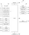
- 1is a block diagram illustrating a mobile terminal.
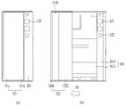
- FIG. 2is a front view of a first state and a second state of a mobile terminal according to an embodiment
- FIG 3is a rear view of a first state and a second state of a mobile terminal according to an embodiment.
- FIGS. 4 and 5are exploded perspective views of a mobile terminal according to an embodiment.
- FIG. 6is a side view of the mobile terminal viewed from the third direction.
- FIG. 7is a diagram illustrating a driving unit according to an embodiment of a mobile terminal.
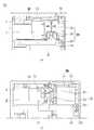
- FIG. 8is a cross-sectional view taken along lines A-A and B-B of FIG. 2 .
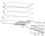
- FIG. 9is a diagram illustrating a display unit and a rolling plate according to an embodiment of a mobile terminal.
- FIGS. 10 and 11are diagrams for explaining a mobile terminal according to an embodiment of the present specification.
- FIG. 12is a functional block diagram of a mobile terminal according to an embodiment of the present specification.
- FIG. 13is a diagram illustrating a flow of each step of a method for controlling a mobile terminal according to an embodiment of the present specification.
- FIG. 14is a diagram specifically illustrating a step of a method for controlling a mobile terminal according to an embodiment of the present specification.
- 15is a diagram illustrating an example of a screen displayed on a mobile terminal according to an embodiment of the present specification.
- 16is a diagram illustrating another example of a screen displayed on a mobile terminal according to an embodiment of the present specification.
- 17is another example of a screen displayed on a mobile terminal according to an embodiment of the present specification.
- 18 and 19are diagrams for explaining a method of controlling a mobile terminal according to an image acquired by the mobile terminal according to an embodiment of the present specification.
- 20is a diagram for explaining a method of controlling a mobile terminal according to an input applied to the mobile terminal according to an embodiment of the present specification.
- 21is a diagram illustrating a mobile terminal according to another embodiment of the present specification.
- 22 and 23are diagrams for explaining a screen displayed on a second surface of a mobile terminal according to an embodiment of the present specification.
- FIG. 1is a block diagram illustrating a mobile terminal (or electronic device) 100 related to the present specification.
- the mobile terminal 100includes a wireless communication unit 110 , an input unit 120 , a sensing unit 140 , an output unit 150 , an interface unit 160 , a memory 170 , a control unit (or processor) 180 , and a power source. It may include a supply unit 190 and the like.
- the components shown in FIG. 1are not essential for implementing the mobile terminal, so the mobile terminal 100 described in this specification may have more or fewer components than those listed above.
- the wireless communication unit 110 among the componentsis between the mobile terminal 100 and the wireless communication system, between the mobile terminal 100 and another mobile terminal 100, or between the mobile terminal 100 and the external server. It may include one or more modules that enable wireless communication between them. In addition, the wireless communication unit 110 may include one or more modules for connecting the mobile terminal 100 to one or more networks.
- the wireless communication unit 110may include at least one of a broadcast reception module 111 , a mobile communication module 112 , a wireless Internet module 113 , a short-range communication module 114 , and a location information module 115 . .
- the input unit 120includes a camera 121 or an image input unit for inputting an image signal, a microphone 122 or an audio input unit for inputting an audio signal, and a user input unit 123 for receiving information from a user, for example, , a touch key, a physical key, etc.).
- the voice data or image data collected by the input unit 120may be analyzed and processed as a user's control command.
- the sensing unit 140may include one or more sensors for sensing at least one of information within the mobile terminal 100 , surrounding environment information surrounding the mobile terminal 100 , and user information.
- the sensing unit 140may include a proximity sensor 141, an illumination sensor 142, an illumination sensor, a touch sensor, an acceleration sensor, a magnetic sensor, and gravity.
- G-sensorgyroscope sensor
- motion sensorRGB sensor
- infrared sensorIR sensor: infrared sensor
- fingerprint sensorfingerprint sensor
- ultrasonic sensorultrasonic sensor
- optical sensorseg, cameras (see 121)
- microphonessee 122
- battery gaugesenvironmental sensors (eg, barometers, hygrometers, thermometers, radiation detection sensors, It may include at least one of a thermal sensor, a gas sensor, etc.) and a chemical sensor (eg, an electronic nose, a healthcare sensor, a biometric sensor, etc.).
- the mobile terminal 100 disclosed in this specificationmay combine and utilize information sensed by at least two or more of these sensors.
- the output unit 150is for generating an output related to visual, auditory or tactile sense, and includes at least one of a display unit 151 , a sound output module 152 , a haptic module 153 , and an optical output unit 154 . can do.
- the display unit 151may implement a touch screen by forming a layer structure with the touch sensor or being formed integrally with the touch sensor. Such a touch screen may function as the user input unit 123 providing an input interface between the mobile terminal 100 and the user, and may provide an output interface between the mobile terminal 100 and the user.
- the interface unit 160serves as a passage with various types of external devices connected to the mobile terminal 100 .
- This interface unit 160a wired / wireless headset port (port), an external charger port (port), a wired / wireless data port (port), a memory card (memory card) port, for connecting a device equipped with an identification module It may include at least one of a port, an audio input/output (I/O) port, a video input/output (I/O) port, and an earphone port.
- the mobile terminal 100may perform appropriate control related to the connected external device.
- the memory 170stores data supporting various functions of the mobile terminal 100 .
- the memory 170may store a plurality of application programs (application programs or applications) driven in the mobile terminal 100 , data for operation of the mobile terminal 100 , and commands. At least some of these application programs may be downloaded from an external server through wireless communication. In addition, at least some of these application programs may exist on the mobile terminal 100 from the time of shipment for basic functions (eg, incoming calls, outgoing functions, message reception, and outgoing functions) of the mobile terminal 100 . Meanwhile, the application program may be stored in the memory 170 , installed on the mobile terminal 100 , and driven to perform an operation (or function) of the mobile terminal 100 by the controller 180 .
- the controller 180In addition to the operation related to the application program, the controller 180 generally controls the overall operation of the mobile terminal 100 .
- the controller 180may provide or process appropriate information or functions to the user by processing signals, data, information, etc. input or output through the above-described components or by driving an application program stored in the memory 170 .
- the controller 180may control at least some of the components discussed with reference to FIG. 1 in order to drive an application program stored in the memory 170 . Furthermore, in order to drive the application program, the controller 180 may operate by combining at least two or more of the components included in the mobile terminal 100 with each other.
- the power supply unit 190receives external power or internal power under the control of the control unit 180 to supply power to each component included in the mobile terminal 100 .
- the power supply 190includes a battery 191 , and the battery 191 may be a built-in battery or a replaceable battery.
- At least some of the respective componentsmay operate in cooperation with each other to implement the operation, control, or control method of the mobile terminal 100 according to various embodiments to be described below. Also, the operation, control, or control method of the mobile terminal 100 may be implemented on the mobile terminal 100 by driving at least one application program stored in the memory 170 .
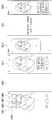
- FIG. 2is a front view of a first state and a second state according to an embodiment of the mobile terminal
- FIG. 3is a rear view of the first state and the second state according to an embodiment of the mobile terminal
- 2 (a) and 3 (a)are views showing a first state in which the mobile terminal is reduced
- FIGS. 2 (b) and 3 (b)are a second state in which the mobile terminal is enlarged. is a diagram showing
- the mobile terminal 100 in the first stateis in a reduced state, and has a smaller size than the mobile terminal 100 in the second state.
- the size of the display unit (or display) 151 positioned on the front of the mobile terminal 100is also smaller than that in the second state.
- the mobile terminal 100 in the first statemay be converted to the second state by expanding in the first direction D1.
- the size of the mobile terminal 100 and the size of the display unit 151 located on the frontare larger than those of the first state, and as shown in FIG. 3(b).
- the size of the display unit 151 located on the rear surfaceis reduced. That is, a portion of the display unit 151 positioned on the rear surface of the mobile terminal 100 in the first state moves to the front surface of the mobile terminal 100 in the second state.
- the direction in which the mobile terminal 100 and the display unit 151 thereof are extended or enlargedis the first direction D1
- the direction in which the mobile terminal 100 and the display unit 151 thereof are extendedis the first direction D1
- a reduced directionis referred to as a second direction D2
- a direction perpendicular to the first and second directions D1 and D2is referred to as a third direction.
- the first direction and the second directionare horizontal directions
- the third directionis described based on the vertical direction. However, depending on the arrangement of the mobile terminal 100 , the first direction D1 and the second direction D2 may become vertical directions. and the third direction may be a horizontal direction.
- the display unit 151may use the flexible display unit 151 that is bent so that the position of the display unit 151 can be changed.
- the flexible display unit 151includes a display (eg, electronic paper) that can maintain a flat state like a conventional flat panel display, and can be bent, bent, folded, twisted, or curled like paper.
- the flexible display unit 151may include a light and strong display that is not easily broken by being manufactured on a thin and flexible substrate.
- the flexible display unit 151may be bent in a specific direction like paper, and may be arranged such that the curvature may change in the first direction.
- Electronic paperis a display technology to which characteristics of general ink are applied, and may differ from conventional flat panel displays in that it uses reflected light. Electronic paper can change information by using a twisted ball or by using electrophoresis using a capsule.
- the display area of the flexible display unit 151becomes a flat surface.
- the display areamay have a curved surface.
- the information displayed in the deformed statemay be visual information output on the curved surface.
- Such visual informationis implemented by independently controlling the light emission of sub-pixels arranged in a matrix form.
- the unit pixelmeans a minimum unit for realizing one color.
- the flexible display unit 151may be combined with a touch sensor to implement a flexible touch screen.
- the controller 180(refer to FIG. 1 ) may perform a control corresponding to the touch input.
- the flexible touch screenmay be configured to sense a touch input not only in the basic state but also in the deformed state.
- the touch sensorsenses a touch (or touch input) applied to the touch screen by using at least one of various touch methods such as a resistive film method, a capacitive method, an infrared method, an ultrasonic method, and a magnetic field method.
- various touch methodssuch as a resistive film method, a capacitive method, an infrared method, an ultrasonic method, and a magnetic field method.
- the touch sensormay be configured to convert a change in pressure applied to a specific part of the touch screen or a change in capacitance occurring in a specific part of the touch screen into an electrical input signal.
- the touch sensormay be configured to detect a position, an area, a pressure at the time of a touch, an electrostatic capacitance at the time of a touch, etc. in which a touch object applying a touch on the touch screen is touched on the touch sensor.
- the mobile terminal 100may be provided with a deformation detection means for detecting the deformation of the flexible display unit 151 .
- a deformation detection meansfor detecting the deformation of the flexible display unit 151 .
- Such deformation detecting meansmay be included in the sensing unit 140 (refer to FIG. 1).
- the deformation detecting meansmay be provided in the flexible display unit 151 or the case (first and second frames 101 and 102 to be described later) to detect information related to deformation of the flexible display unit 151 .
- the information related to the deformationmay be a direction in which the flexible display unit 151 is deformed, a deformed degree, a deformed position, a deformed time, and an acceleration at which the deformed flexible display unit 151 is restored.
- the flexible display unit 151may be various types of information detectable due to bending.
- the controller 180changes information displayed on the flexible display unit 151 based on the information related to the deformation of the flexible display unit 151 sensed by the deformation detecting means, or the mobile terminal 100. It is possible to generate a control signal to control the function of
- the deformation of the flexible display unit 151may vary depending on the positions of the first frame 101 and the second frame 102 . As shown in FIG. 2 , since the bent position of the flexible display unit 151 is determined according to the positions of the first frame and the second frame, the first frame 101 and the second frame instead of the deformation detecting means of the flexible display unit 151 are determined. 2 Depending on the position of the frame 102 , the bending deformation position and the front area of the flexible display unit 151 may be calculated.
- the change of the state of the flexible display unit 151may be performed manually by a force applied by the user, but is not limited to such a passive manner.
- the mobile terminal 100 or the flexible display unit 151may be transformed into a second state by a command from a user or an application without an external force applied by the user.
- the mobile terminal 100may include a driving unit 200 to be described later.
- the flexible display unit 151 of the present specificationis bent 180 degrees while wrapping around the side of the mobile terminal 100 in the first direction. Accordingly, a part of the flexible display unit 151 is disposed on the front side of the mobile terminal 100 based on the side of the mobile terminal 100 , and the other part of the flexible display unit 151 is located on the rear surface of the mobile terminal 100 . are placed
- the flexible display unit 151 located at the frontis referred to as a front side
- the flexible display unit 151 located at the rear sideis referred to as a back side.
- the mobile terminalmay be expanded in a first direction or contracted in a second direction opposite to the first direction. In this case, the area of the flexible display unit 151 located on the front side is changed. That is, the sizes of the front part and the rear part may vary according to a change in the state of the mobile terminal.
- a part of the flexible display unit 151 located on the front of the mobile terminal 100may be fixed immovably on the front of the first frame 101 , and the other part of the flexible display unit 151 located on the rear side of the mobile terminal 100 is It may be provided movably on the rear surface.
- the flexible display unit 151may be wound or unwound from the side of the mobile terminal 100 in the first direction, and accordingly, by moving a portion disposed on the rear surface of the mobile terminal 100, the flexible display unit ( 151), the size of the area disposed in front of the mobile terminal 100 may be adjusted. Since the area of the flexible display unit 151 is fixed and it is composed of one continuous body, when the area of the front portion increases, the area of the rear portion decreases. Such a display unit 151 may be wound in a second frame 102 relatively movable to a first frame 101 to be described later, more precisely, on a side of the second frame 102 in the first direction. .
- the display unit 151is wound around the second frame 102 according to the moving direction of the second frame 102 so as to adjust the area of the display unit 151 in the front of the mobile terminal 100 , the second frame. may be withdrawn or pulled out from or inserted or pushed into 102 . This operation will be described in more detail below along with other related components of the mobile terminal 100 .
- the antennais provided in the case or housing of the mobile terminal 100, but the portion where the antenna is installed in the case or housing is limited by the flexible display unit 151 that covers the front and rear surfaces of the mobile terminal 100. can be For this reason, an antenna may be implemented on the flexible display unit 151 .
- Antenna on display (AOD)is a type of antenna in which a patterned electrode layer and a dielectric layer are layered to form a transparent film.
- the built-in display antennacan be implemented thinner than the laser Direct Structuring (LDS) technology implemented by the existing copper nickel plating method, so it has the advantage of not being exposed to the outside with little effect on the thickness.
- the built-in display antennamay directly transmit/receive a signal from the display unit 151 . Accordingly, in the mobile terminal 100 in which the display unit 151 is positioned on both sides as in the present specification, a built-in display antenna may be used.
- FIG. 4 and 5are exploded perspective views of a mobile terminal according to an embodiment. More specifically, FIG. 4 is an exploded perspective view viewed from the front direction, and FIG. 5 is an exploded perspective view viewed from the rear side.
- the mobile terminal 100 of the present specificationincludes frames 101 and 102 on which components are mounted, and the frames 101 and 102 of the present specification may vary in size in the first direction as shown in FIG. 2 . . At least one or more frames 101 and 102 may move relatively and have different sizes in the first direction.
- the frames 101 and 102have electronic components mounted therein and the flexible display unit 151 positioned outside.
- the flexible display unit 151may be coupled to cover the front and rear surfaces of the frames 101 and 102 .
- the framemay include a first frame 101 and a second frame 102 moving in a first direction with respect to the first frame 101 .
- the first frame 101 and the second frame 102include a front portion, a rear portion and a side portion, and are coupled to each other.
- the first frame 101corresponds to the main body of the mobile terminal 100 , and a space for accommodating various parts may be formed between the first front part 1011 and the first rear part 1012 .
- the first frame 101may accommodate the second frame 102 movably coupled to the first frame 101 in such a space.
- the first frame 101is disposed at the front of the mobile terminal 100 and supports the front part of the display unit 151 with the first front part 1011 . ) and disposed at the rear of the mobile terminal and may include a first rear portion 1012 on which various components are mounted.
- the first front portion 1011 and the first rear portion 1012may be spaced apart from each other at a predetermined distance to form a predetermined space, and the first side portion (1013) can be connected to each other.
- the first side portion 1013may be formed integrally with the first rear portion 1012 or the first front portion 1011 .
- a camera 121 , a sound output module 152 , an input/output terminal 161 , a control unit 180 , and a power supply unit 190may be accommodated as components of the mobile terminal 100 in the space within the first frame 101 .
- the control unit 180may be a circuit board 181 including a processor and an electronic circuit for controlling the operation of the mobile terminal 100
- the power supply unit 190includes the battery 191 and related parts.
- the driving unit 200 for controlling the sliding movement of the second frame 102 to be described latermay also be accommodated in the first frame 101 .
- the display unit 151has a continuous body and may be disposed on both the front and rear surfaces of the mobile terminal 100 while being wound in the mobile terminal 100 .
- the display unit 151may include a front portion positioned on the front of the mobile terminal 100 , a rear portion positioned on the rear surface, and a side portion positioned between the front portion and the rear portion and surrounding the side surface of the mobile terminal 100 .
- the display unit 151 of the front part and the rear partmay be flat, and the display part 151 of the side part may form a curved surface.
- the flexible display unit 151When the flexible display unit 151 is bent at an angle, the flexible display unit 151 may be damaged, and the side portion may be configured to be bent with a predetermined curvature.
- the display unit 151may be divided into a fixed unit and a variable unit.
- the fixing partmeans a part fixed to the frame. Since the fixing part is fixed to the frame, it is characterized in that the degree of bending does not change and maintains a constant shape.
- the variable partmeans a part in which the angle of the curved part is variable or the position of the curved part is changed.
- the variable portion in which the bending position or angle is changedneeds a structure for supporting the rear surface of the variable portion in response to the change.
- the fixing partis coupled to the first frame 101 of the display unit 151 and is located on the front side to constitute a part of the front part.
- the variable partincludes a side part positioned in the side direction of the mobile terminal, and the position of the side part changes according to the position of the second frame 102 .
- the area of the area located on the front side and the area located on the back sideare different from the side part. That is, a part of the variable part may be a front part and a part of the variable part may be a rear part according to the first state and the second state.
- a variable portionis positioned in a first direction with respect to a fixed portion (eg, the first region 151a and the second region 151b) with respect to the mobile terminal 100 , and the end of the variable portion is positioned in the rear direction of the mobile terminal 100 . It is bent and can slide on the rear surface of the second frame 102 .
- the end of the variable part of the display unit 151is coupled to a slide frame 103 that guides the slide movement on the rear surface of the second frame, and the slide frame is connected to the second frame 102 at the same time when the second frame 102 moves in the first direction. ) in the first direction.
- the moving distance of the slide frame 103moves twice as much as the second frame 102 with respect to the first frame 102 .
- the first rear portion 1012 of the mobile terminal 100has an exposed rear portion 1015 exposed to the outside without the display unit 151 covering it even in the first state.
- the first rear portion 1012 excluding the exposed rear portion 1015is covered by the display unit 151 in the first state as shown in FIG. In the second state, it may be exposed in the rear direction.
- the display unitis provided only on the front surface of the terminal. Accordingly, the main camera is disposed on the rear surface of the terminal in order to photograph the opposite object while looking through the user's display unit. On the other hand, an auxiliary camera is additionally required on the front of the terminal in order to take a picture while looking at the user through the display unit.
- the display unit 151is positioned on both the front and rear surfaces thereof. Therefore, when photographing the user himself, the display unit 151 on the same side as the camera 121, that is, the rear portion of the display unit 151 may be used, and when photographing an object opposite to the user, the camera 121 and the opposite side The front portion of the display unit 151 in the . For this reason, the mobile terminal 100 may use one camera 121 to photograph an object located on the opposite side of the user or may photograph the user.
- the cameramay include a plurality of cameras having different angles of view, such as wide-angle, ultra-wide, and telephoto.
- a proximity sensor sound output unitmay be positioned on the exposed rear part 1015 , and an antenna 116 may be installed.
- An exposed decorationmay be attached to protect the camera or sensor of the exposed rear portion 1015 and to consider the exterior design aspect.
- the part corresponding to the camera 121 or the sensor 140is configured to be transparent, and the internal parts are not exposed in the other part, and may have a predetermined pattern or color in consideration of the design aspect.
- the first side portion 1013may extend along the edges of the first front portion 1011 and the first rear portion 1012 so as to surround the circumference of the first frame 101 , and may enhance the appearance of the mobile terminal 100 . can be formed However, as mentioned above, since the second frame 102 is accommodated in and movably coupled to the first frame 101 , the relative movement of this second frame 102 with respect to the first frame 101 . A part of the first frame 101 needs to be opened in order to allow this.
- the first side portion 1013is disposed on the side surface in the first direction. It is not formed and can open it. Since the first side portion 1013 is exposed to the outside of the mobile terminal 100 , an interface unit 160 for connecting a power port or an ear jack or a user input unit 120 such as a volume button may be disposed. When a metal material is included, the first side portion 1013 may serve as an antenna.
- the second frame 102may include a second front portion 1021 disposed in front of the mobile terminal 100 and a second rear portion 1022 disposed in the rear of the mobile terminal 100 .
- the second front portion 1021 and the second rear portion 1022may be formed of a substantially flat plate-shaped member.
- the second frame 102also accommodates various parts, and should not interfere with the parts accommodated in the first frame 101 during movement. Accordingly, the second front portion 1021 and the second rear portion 1022 may be coupled to each other in a spaced apart state to form a predetermined space, and may have a shape that does not interfere with the components in the first frame 101 . have.
- FIG. 6is a side view of the mobile terminal 100 viewed from the third direction, showing a first side portion 1013 of the first frame 101 and a second side portion 1023 of the second frame 102 .
- the end of the second frame 102 in the first directionis not exposed to the outside because the flexible display unit 151 is located, and the end of the second frame 102 in the second direction should be opened so as not to interfere with the first frame 101 .
- the second side portion 1023 of the second frame 102 positioned in the third direction(meaning the upper or lower direction in the drawing, or may include both the upper and lower sides) has a first frame 101 in the first state. ) overlaps with the first side 1013 and is not exposed to the outside, but in the second state, since the second frame 102 is drawn out, it may be exposed to the outside.
- the display unit 151may be bent 180 degrees while being wound in the second frame 102 so as to be disposed on both the front and rear surfaces of the mobile terminal 100 .
- the second frame 102may include a roller 210 rotatably disposed therein.
- the roller 210may be disposed at any position inside the second frame 102 .
- the display unit 151needs to be spread flat on the front and rear surfaces of the mobile terminal 100 in order to provide a user with a good quality screen.
- a roller 210may be disposed at the first directional end of the second frame 102 .
- the roller 210may extend in the second direction and may be rotatably coupled to the second frame 102 .
- the display unit 151may be wound around the roller 210 while being gently bent with a predetermined curvature.
- the flexible display unit 151may include a first surface on which an image is output and exposed to the outside, and an inner surface facing the frame opposite to the first surface.
- the roller 210may be installed to freely rotate on the second frame 102 while in contact with the inner surface of the display unit 151 . Accordingly, the roller 210 may actually move the display unit 151 in a lateral direction of the mobile terminal 100 , that is, in a direction perpendicular to the longitudinal direction.
- the display unit 151is relative to the second frame 102 by the tension applied by the second frame 102 and moves in different directions (that is, , the first direction (D1) or the second direction (D2)) can move to the front or rear of the mobile terminal 100 .
- the roller 210may guide the movement of the display unit 151 while rotating.
- roller 210is disposed adjacent to the end of the second frame 102 in the first direction, and in order to prevent damage to the display unit 151 wound around the roller 210 , the first frame of the second frame 102 . and a side frame 1024 disposed at the directional end.
- the side frame 1024may extend long in the longitudinal direction (third direction) of the second frame 102 to cover the side portion in the first direction, and accordingly, the roller 210 and the display unit 151 wound thereon. can protect Also, the position of the side frame 1024 may vary according to the state of the mobile terminal 100 .
- the sidehas a predetermined curvature and is wound by the roller 210 , and the inner surface of the side frame 1024 may include a curved surface corresponding to the curvature of the side.
- the side frame 1024 together with the first side portion 1013 of the first frame 101may substantially form the appearance of the mobile terminal 100 . Also, the side in the second direction of the second frame 102 may be omitted to minimize interference with components in the first frame 101 during movement.
- the second frame 102does not interfere with the first frame 101 , the first frame 101 , precisely its first
- the front portion 1011 and the first rear portion 1012may overlap. More specifically, as described above, the display unit 151 may be coupled and supported by the first front portion 1011 of the first frame 101 , and thus the second frame 102 . There is no need to be additionally supported by the second front portion 1021 of
- the second front portion 1021when the second front portion 1021 is positioned between the first front portion 1011 and the display portion 151 , the display portion 151 is deformed due to friction with the repeatedly moving second front portion 1021 . or may be damaged. Accordingly, the second front portion 1021 may be disposed below the first front portion 1011 or may be inserted between the first front portion 1011 composed of two sheets.
- the second rear portion 1022 of the second frame 102may be disposed in a rear direction of the first rear portion 1012 of the first frame 101 . That is, the front surface of the second rear portion 1022 may face the rear surface of the first rear portion 1012 .
- the rear surface of the first rear portion 1012may contact the front surface of the second rear portion 1022 .
- the second rear portion 1022is exposed to the outside of the first frame 101 , precisely the first rear portion 1012 , and may be coupled to the display unit 151 .
- the second frame 102can expand and contract the size of the mobile terminal 100 itself, in particular, the front of the mobile terminal 100 by expansion and contraction in the first and second directions D1 and D2. have.
- the display unit 151needs to be moved by the expanded or reduced front surface.
- the display unit 151may be movably coupled to the second frame 102 .
- the display unit 151includes a second region ( 151b), located between the first area 151a and the second area 151b, and wrapped around the roller 210, and moved to the front or the back according to the state change of the mobile terminal 100 It may include three regions 151c.
- the slide frame 103may be formed of a plate-shaped member extending long in the longitudinal direction (third direction) of the mobile terminal 100,
- Itmay be movably coupled to the second rear part 1022 in the first direction D1 and the second direction D2 .
- the first region 151a , the second region 151b , and the third region 151a , 151b , and 151care connected to each other and may form a continuous body of the display unit 151 .
- the first region 151ais formed by the mobile terminal. It is fixed to the front surface of 100 and the second area 151b may be provided to be movable on the rear surface of the mobile terminal.
- the configuration of the display unit 151will be described in more detail below.
- the first region 151amay be disposed on the front surface of the mobile terminal 100 , more specifically, on the front surface of the first front part 1011 of the first frame 101 .
- the first region 151ais fixed to the front surface of the first frame 101 , that is, the first front part 1011 , so that it does not move even when the second frame 102 is moved, and thus the mobile terminal 100 is always can be exposed to the front.
- the third region 151cis adjacent to the first region 151a in the direction of the second end 151e , and may extend into the second frame 102 to be wound around the roller 210 .
- the third region 151cmay extend out from the second frame 102 again and partially cover the second frame 102 , that is, the rear surface of the second rear portion 1022 .
- the second frame 102that is, the second rear portion 1022 is adjacent to the first frame 101, that is, the first rear portion 1012 and together form the rear case of the mobile terminal 100, It may be described that the third region 151c is also disposed on the rear surface of the first frame 101 .
- the second region 151bis adjacent to the third region 151c and may be disposed on the rear surface of the mobile terminal 100 , and more particularly, on the rear surface of the second rear part 1022 of the second frame 102 . have.
- the second region 151bmay be coupled to the slide frame 103 without being directly coupled to the second frame 102 .
- the first region 151ais disposed on the front surface of the mobile terminal 100 and is always exposed to the front regardless of the movement of the second frame 102
- the second region 151bis the mobile terminal 100 . It is disposed on the rear surface of the second frame 102, regardless of the movement can be always exposed to the rear surface.
- the third region 151cis disposed between the first and second regions 151a and 151b, and the front or rear surface of the mobile terminal 100 according to the moving directions D1 and D2 of the second frame 102 . may be selectively placed on the
- the first rear portion 1012 of the first frame 101is in the first state in the second region 151b and the third region of the display unit 151 .
- the third region 151cmoves toward the front of the mobile terminal 100, and the second rear portion 1022 also moves in the first direction. Since it moves to (D1), it may be exposed to the outside of the mobile terminal 100 .
- the second front portion 1021 of the second frame 102is hidden by the first front portion 1011 of the first frame 101 in the first state, but in the second state, the first frame 101
- the third region 151c of the display unit 151 that is moved from and is disposed on the front of the mobile terminal 100may be supported.
- the second front portion 1021may further include a separator positioned in the rear direction of the second front portion 1021 so as not to affect the internal components during sliding movement to be coupled to the first front portion 1011 .
- the second front part 1021may move between the first front part 1011 and the separation plate according to the sliding movement of the second frame 102 .
- the third region 151cmay be bent by being wound around the roller 210 in the second frame 102 .
- the third region 151cmay extend from the second frame 102 to the front of the mobile terminal 100 while being wound around the roller 210 in either direction.
- the third region 151cmay be contracted from the front side of the mobile terminal 100 to the second frame 102 while being wound around the roller 210 in the opposite direction, and at the same time. It is possible to return to the rear surface of the mobile terminal 100 from the second frame 102 .
- the deformable portion of the flexible display unit 151that is, the portion wound around the roller 210 may vary according to the first and second states of the mobile terminal 100 , that is, the movement of the second frame 102 . . Accordingly, the mobile terminal 100 of the present specification can significantly reduce deformation and fatigue repeatedly applied to a specific portion of the display unit 151, thereby preventing the display unit 151 from being damaged.
- the overall operation of the mobile terminal 100will be described as follows.
- state changemay be performed manually by a user, and the operation of the mobile terminal 100 during such manual state change will be described.
- the operations of the 1-3 frames 101-103 and the display unit 151 described beloware performed when a power source other than the user's power is used, for example, when the driving unit 200 to be described later is applied. can be performed in the same way.
- a rear cover 1025may be further provided on the rear surface of the second rear portion 1022 so that the rear portion of the display unit 151 located on the rear surface of the mobile terminal 100 is not exposed to the outside.
- the rear cover 1025can be used in the first state when a transparent material is used, and when an opaque material is used, the slide frame 103 can be covered so as not to be exposed. That is, the second and third regions of the slide frame 103 and the display unit 151 move in the first direction and the second direction between the spaced apart space between the second rear part 1022 and the rear cover 1025 .
- the mobile terminal 100 of the present specificationis a mobile terminal 100 in such a way that the user manually pulls the second frame 102 with respect to the first frame 101 or pushes it in the second direction.
- the motor 201when excessive force is applied to the main body of the mobile terminal 100, there is a risk of damage, so that the motor 201 can be moved to stably move the second frame 102 without distortion. It may further include a driving unit 200 to be used.
- the motor 201may use a motor 201 that provides a rotational force as shown in FIG. 7 , or a linear motor 201 that moves in a straight line.
- the motor 201 providing the rotational forcemust have a larger diameter, but in order to provide a driving force of a predetermined size or more without increasing the thickness in the limited space of the mobile terminal 100.
- two motors 201can be used. If the moving speed of the second frame 102 is too fast, there is a risk of damage or malfunction, so it may further include a planetary gear for decelerating the speed of the motor 201 to move at a stable speed.
- the planetary gear 202serves to amplify or attenuate the number of rotations of the motor 201 using a plurality of disk gears having different numbers of teeth.
- the motor 201may be fixed to the first frame 101 as shown in (a) of FIG. 7, and as shown in (b) of FIG. Even if the mobile terminal 100 is moved to the second state, the position is fixed.
- the second frame 102may use a rack and pinion gear that converts the rotational force of the motor 201 into a linear motion because it linearly moves in the first direction or the second direction with respect to the first frame 101 .
- the pinion gear receiving the rotational force of the motor 201may be disposed to mesh with the rack gear 205 composed of teeth continuously arranged in the first direction.
- the pinion gearmay be fixed to the first frame 101 together with the motor 201 , and the rack gear 205 may be located in the second frame 102 .
- the rack gear 205may be disposed on the first frame 101 and the motor 201 and the pinion gear may be disposed on the second frame 102 .
- the second frame 102can maintain the first state and the second state, but when a large external force is applied, the pinion gear rotates while the second frame ( 102) may be out of position.
- the mobile terminal 100may further include a stopper (not shown) for fixing the position between the second frame 102 or the rack gear 205 and the first frame 101 so that the mobile terminal 100 is fixed in the first state or the second state.
- a stopper(not shown) for fixing the position between the second frame 102 or the rack gear 205 and the first frame 101 so that the mobile terminal 100 is fixed in the first state or the second state.
- the stopperis released when a current flows through the motor 201 to allow movement of the second frame 102, and when the motor 201 does not rotate because power is not applied to the motor 201, the second frame ( 102) and the second frame 102 may be fastened to fix the position.
- the second frame 102may further include a linear guide 230 because, depending on the position of the asymmetric driving unit 200 , the moving speed of the upper end and the lower end is different during the movement of the second frame 102 , which may cause a problem in that it is twisted.
- the linear guide 230may be disposed at both ends of the mobile terminal 100 in the third direction, ie, upper and lower, in order to supplement the function of one driving unit 200 biased to one side in the third direction.
- the linear guide 230may include a guide rail 231 extending in the first direction and a guide block 232 moving along the guide rail 231 .
- the guide rail 231may be disposed on the first frame 101 and the guide block 232 may be disposed on the second frame 102 , and vice versa.
- the guide rails 231are disposed on the second frame 102 to cover upper and lower sides of the extended portion of the second frame 102 in the second state.
- the guide block 232 and the guide rail 231may be slide-fastened, but fastening
- the guide block 232is first fixed to the first frame 101, and then the second frame 102 and the guide rail 231 are can be combined.
- a guide groove into which the guide rail 231 is insertedmay be formed, and conversely, a rail groove into which a part of the guide block 232 is inserted may be formed in the guide rail 231 .
- the fastening portion of the guide rail 231 and the guide block 232may be moved in the first direction or the second direction without being deviated in the thickness direction of the mobile terminal 100 as unevenness is formed.
- a member with high wear resistance, low friction resistance, and self-lubricationsuch as a bearing or polyoxymethylene (POM), is added inside the guide groove. can do.
- FIG. 8is a cross-sectional view taken along lines A-A and B-B of FIG. 2 .
- FIG. 8(a)is a cross-sectional view taken along line A-A of FIG. 2
- FIG. 8(b)is a cross-sectional view taken along line B-B of FIG.
- FIG. 2when the second frame 102 moves in the first direction and is converted to the second state, the third region 151c located in the rear direction moves in the front direction and the second frame 102 moves in the front direction. 3 A structure supporting the rear surface of the region 151c is required.
- the second front portion 1021 positioned on the front side of the second frame 102may be positioned on the rear surface of the third region 151c in the second state, but in the first state, the first Since it overlaps with the front part 1011, the first front part 1011 and the second front part 1021 form a step difference.
- a boundaryis generated between the first area 151a and the third area 151c of the flexible display unit 151 due to the step difference between the first front portion 1011 and the second front portion 1021 .
- the rolling plate 104may be used as a support structure to fill a space between the second front part 1021 and the third region 151c of the flexible display unit 151 .
- the rolling plate 104is positioned on the rear surface of the flexible display unit 151 and may have a thickness corresponding to the spaced apart space between the second front unit 1021 and the flexible display unit 151 in the second state.
- the rolling plate 104in the first state, is wound around the roller 210 and is positioned in the side and rear directions of the mobile terminal 100 , and the second rear of the second frame 102 .
- the flexible display unit 151 and the rolling plate 104may be positioned between the unit and the rear cover 1025 that covers the rear surface of the display unit 151 .
- the rolling plate 104when switching to the second state, the rolling plate 104 moves to the front, and the rolling plate 104 may be located in the front portion of the second frame 102 .
- the rolling plate 104Since the third region 151c of the display unit 151 in which the rolling plate 104 is located is a portion in which bending deformation occurs when the first state is changed to the second state, the rolling plate 104 also includes the third region 151c. It can be modified corresponding to the modification of . At the same time, the rolling plate 104 must have a certain rigidity to maintain a flat state when the flexible display unit 151 is positioned on the front or rear surface. That is, the rolling plate 104 needs a structure that maintains a flat state in the third direction and is bendable in the first direction.
- FIG. 9is a view showing a display unit 151 and a rolling plate 104 according to an embodiment of the mobile terminal 100, wherein the rolling plate 104 includes a plurality of support bars 1041 extending in a third direction. may include.
- the plurality of support bars 1041are arranged side by side in the first direction, are spaced apart from each other by a predetermined distance, and are wound around the roller 210 to avoid interference between the support bars 1041 even when the flexible display unit 151 is bent.
- the support bar 1041may be implemented as an injection-molded material having a predetermined thickness for rigidity, and may include a metal material such as SUS.
- the plurality of support bars 1041may be directly attached to the rear surface of the display unit 151 , but it may take a long time and cause many defects, thereby reducing productivity. In addition, when the display unit 151 is directly processed, there is a high possibility that the display unit 151 may be damaged. Accordingly, an embodiment of the mobile terminal 100 may further include a rolling seat 1045 for fixing the plurality of support bars 1041 .
- the rolling sheet 1045may include a metal material, and a material having superelasticity that can be bent and deformed and can maintain a flat state again after bending can be used.
- a superelastic metal sheetsuch as a thin STS sheet of 0.05 mm or less can be used.
- An adhesive tapemay be attached to both sides of the rolling sheet 1045 in order to couple the rolling sheet 1045 and the support bar 1041 to the back surface of the display unit 151 and the rolling sheet 1045 .
- the rolling sheet 1045itself may also form a kerf pattern in which a plurality of grooves extending in the third direction are formed in the first direction.
- the groove of the cuff patternmay be formed between the plurality of support bars 1041 , and is preferably formed on the surface to which the support bars 1041 of the rolling sheet 1045 are coupled.
- the cuff patternmay be configured in a wedge shape in which the surface portion of the rolling sheet 1045 has a large size and gradually becomes narrower.
- a material having elasticitysuch as silicone, is disposed between the support bars 1041 instead of the rolling sheet 1045 to couple the adjacent support bars 1041, and the angle between the support bars 1041 is variable. can do.
- the elastic connection partmay be bent at a position corresponding to the roller 210 , and if it is located on the front or rear surface, the support bar 1041 may be spread out so that it forms a plane.
- the support bar 1041may have a flat surface corresponding to the rear surface of the display unit 151 .
- the support bar 1041may be configured to have a predetermined curvature.
- the curved support bar 1041may be in close contact with the curved surface of the roller 210 when the rolling plate 104 is wound around the roller 210 .
- one surface of the support bar 1041 in contact with the display unit 151may maintain a flat plane, and the other surface of the support bar 1041 may include a curved surface having a curvature corresponding to the curvature of the roller 210 .
- the thickness of the support bar 1041may be formed so that the ends in the first direction and the second direction are thick and the middle is the thinnest.
- the rolling plate 104is disposed at a position corresponding to the third region 151c and is wound around the roller 210 so as to span the front and rear surfaces. In the front direction, it is connected to the first front portion 1011 of the first frame 101 , and in the rear direction, it is connected to the slide frame 103 .
- the slide frame 103 positioned at , and a surface in contact with the display unit 151 of the rolling plate 104 positioned on the rear surface of the third region 151cmay have the same height.
- the thickness of the rolling plate 104has a thickness corresponding to the thickness of the slide frame 103 .
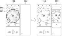
- FIG. 10 and 11are diagrams for explaining a mobile terminal according to an embodiment of the present specification.
- FIG. 10shows an example in which an image acquired through a camera is displayed on displays disposed on the first and second surfaces of the mobile terminal.
- 11illustrates an example in which an image acquired through a camera is displayed on a display disposed on a second surface of a mobile terminal.
- displaying the acquired imagemay include continuously displaying images captured by the camera, and the user confirms a portion captured by the camera through the displayed image, and presses the shooting button
- a specific image or videomay be stored by providing the same input to the terminal.
- a displaymay be disposed on the first side and the second side of the mobile terminal.
- Contenteg, an image
- a first screen 1001may be displayed on the display of the first surface of the mobile terminal.
- the second screen 1002 or the third screen 1003is displayed on the display of the second surface of the mobile terminal.
- the first surfacemay correspond to the front surface of the mobile terminal, and the second surface may correspond to the rear surface of the mobile terminal.
- the first screen 1001may be displayed on the first area of the first surface, and the second screen 1002 or the third screen 1003 may be displayed on the second area of the second surface.
- the first areamay include a predetermined area of the first surface, and the second area may include a predetermined area of the second surface.
- the first screen 1001 of FIG. 10may be a screen displayed in response to execution of a camera-related application (eg, a camera application).
- the first screen 1001may include an image 1004 acquired through the camera and a control icon 1006 for controlling an application related to the camera.
- the image 1004may include an image (or image preview) acquired in real time through a camera.
- the present inventionis not limited thereto and may include an image acquired through a camera (eg, an image most recently acquired through a camera) according to embodiments.
- the control icon 1006is not limited to the above-described example, and may include various icons for controlling applications related to the camera, and may be freely arranged in various positions on the first screen 1001 .
- the display of the second screen 1002 or the third screen 1003is displayed on the first screen 1001
- Notification content 1005 for notifyingmay be displayed.
- the display of the notification content 1005may be omitted.
- the second screen 1002 or the third screen 1003 of FIG. 10is a screen displayed on the display of the second surface, and may include an image 1050 obtained through a camera.
- the second screen 1002represents a screen in which a control icon of a camera-related application is briefly displayed
- the third screen 1003is a control icon (eg, a first control icon 1055 , a second control icon 1054 ).
- the third control icon 1056)may indicate a screen in which more details appear.
- the image 1050 obtained through the camera of the second screen 1002 or the third screen 1003may correspond to the image 1004 obtained through the camera of the first screen 1004 .
- image 1050may be a reduced image of image 1004 .
- the image 1050may be an image in which the image 1004 is reduced and left and right inverted.
- the first control icon 1055when an input is applied to the first icon 1051 of the second screen 1002 , the first control icon 1055 , the second control icon 1054 , and the third control such as the third screen 1003 . Icon 1056 may appear.
- the second screen 1002 or the third screen 1003may include a second icon 1052 .
- the provision of the second screen 1002 or the third screen 1003may be terminated.
- content representing time informationmay be displayed on the second screen 1002 or the third screen 1003 , but the present invention is not limited thereto, and the time information may be omitted in some cases.
- the camera acquiring the images 1004 and 1050may be located on a second side of the mobile terminal, and accordingly, the object included in the images 1004 and 1050 may be located at the direction of the second side.
- the image 1050is displayed on the display of the second surface as well as the first surface, information about the images 1006 and 1050 to both the user controlling the mobile terminal in the direction of the first surface and the object of the images 1006 and 1050
- FIG. 11illustrates a case in which a first screen 1101 with limited functions is displayed on a first surface, and a second screen 1102 including an image obtained through a camera is displayed on a second surface.
- the first screen 1101may include a screen in which at least some functions of the first screen 1001 of FIG. 10 are restricted.
- the first screen 1101may include a screen in which input to a control icon of a camera-related application is restricted.
- the first screen 1101may include a screen provided based on inactivation of touch input detection. In this case, for example, the text 'You can use the camera on the rear screen' may be included in the first screen 1101 and displayed on the display.
- the second screen 1102may correspond to the third screen 1003 of FIG. 10 , but is not limited thereto and may correspond to the second screen 1002 of FIG. 10 .
- the mobile terminalwhen the first screen 1101 is displayed on the display of the first side as shown in FIG. 11 and the second screen 1102 is displayed on the display of the second side, the mobile terminal is turned over and the camera disposed on the rear side
- Thismay include situations where the user is taking a selfie.
- the input through the first surfaceis limited and the input through the second surface is sensed, erroneous input to the first surface due to the grip posture of the mobile terminal can be prevented, and accordingly, the malfunction of the mobile terminal can be prevented.
- a camera disposed on the second surfaceis capable of high-performance shooting compared to a camera disposed on the first surface, and as such, a UI capable of taking a selfie through the second surface is provided, thereby enabling more diverse shooting.
- FIG. 12is a functional block diagram of a mobile terminal according to an embodiment of the present specification.
- An element of the mobile terminal 1200which will be described later, means a unit for processing at least one function or operation, which may be implemented as hardware or software, or a combination of hardware and software.
- the mobile terminal 1200may include a display 1201 , a camera 1202 , and a controller 1203 .
- the display 1201may be arranged such that the size exposed on the first surface of the mobile terminal 1200 (eg, the front surface of the mobile terminal 1200) is changed.
- the size exposed on the first surface of the display 1201may be changed based on the control of the controller 1203 to be described later.
- a portion of the display 1201may be disposed on the first surface of the mobile terminal 1200 and another portion may be disposed on the second surface of the mobile terminal 1200 .
- a first area of the display 1201may be disposed on a first surface of the mobile terminal 1200
- a second area of the display 1201may be disposed on a second surface opposite to the first surface.
- the first surfacemay include a front surface of the mobile terminal 1200
- the second surfacemay include a rear surface of the mobile terminal 1200 opposite to the first surface.
- a part of the display 1201may be disposed on the first surface and the other part may be wound on one surface of the mobile terminal 1200 and disposed on the second surface of the mobile terminal 1200 .
- the display 1201may be bent at one end in contact with the first surface, at least a portion of it may be disposed on the first surface, and at least another portion of the display 1201 may be disposed on the second surface contacting the end.
- the present inventionis not limited thereto, and the display 1201 may be disposed separately on the first surface and the second surface opposite to the first surface.
- the display 1201may display content for an application that is provided based on execution of an application (eg, a camera application) or content indicating the application.
- an applicationeg, a camera application
- the camera 1202may be disposed on the second surface (eg, the rear surface of the mobile terminal 1200 ).
- the camera 1202may be positioned to be spaced apart from the display 1201 on the second side.
- the area where the camera 1202 is located and the area where the display 1201 is locatedmay be distinguished.
- the display of the second surfaceThe distance between the area of 1201 and the area of camera 1202 may be changed. For example, if the size exposed on the first surface of the display 1201 increases, the size of the display 1201 exposed on the second surface may decrease, correspondingly to the display 1201 and the camera on the second surface. By being spaced apart between 1202 , the distance between the display 1201 of the second side and the camera 1202 may increase.
- the region where the camera 1202 is positioned and the region where the display 1201 is positionedmay be connected through a hinge, and accordingly, the camera 1202 and the display 1201 positioned together on the second surface move the hinge.
- the halvesmay be located on different sides.
- the region where the camera 1202 is positioned and the region where the display 1201 is positionedare changed to have a predetermined angle with respect to the hinge, so that the display 1201 is positioned on the second surface and the camera 1202 is positioned on the second surface. may be located on the third surface.
- camera 1202may include a plurality of cameras.
- the camera 1202may include a plurality of cameras each having a different lens applied thereto.
- the camera 1202may acquire information about an object or space in a direction opposite to the lens of the camera 1202 based on the control of the controller 1203, which will be described later, to generate an image.
- the image generated by the camera 1202may include a person image.
- the camera 1202since it is easy for those skilled in the art, a detailed description thereof will be omitted.
- the mobile terminal 1200may include at least one sensor.
- the at least one sensormay include, for example, a posture detection sensor for detecting the posture of the mobile terminal 1200 .
- the posture detection sensormay include a sensor for detecting the posture of the mobile terminal 1200 based on angle or direction sensing, such as a gyro sensor, but is not limited thereto, and various sensors within the scope that are easy for a person skilled in the art may be included. can
- the controller 1203may control the mobile terminal 1200 or components of the mobile terminal 1200 .
- the controller 1203may control the operation of the display 1201 or the camera 1202 by executing a command or an application program stored in the memory.
- the controller 1203may acquire an image using the camera 1202 .
- the controller 1203may acquire an image by driving the camera 1202 based on the execution of an application related to the camera.
- the controller 1203may display an image acquired through the camera 1202 on the display 1201 . More specifically, the controller 1203 may display the image acquired through the camera 1202 on at least one of the first area of the first surface and the second area of the second surface of the display 1201 . For example, the controller 1203 may display the image acquired through the camera 1202 on at least one of the first area of the first surface and the second area of the second surface of the display 1202 .
- the controller 1203may determine whether information sensed through at least one sensor (eg, a posture detection sensor) corresponds to the first condition or the second condition.
- the first conditionmay include a case where the posture of the mobile terminal 1200 corresponds to the first posture.
- the second conditionmay include, for example, a case in which the posture of the mobile terminal 1200 corresponds to the second posture.
- the first postureis a posture in which the user looks at the first side (eg, the front side) of the mobile terminal 1200
- information sensed by the sensormay include a posture corresponding to the first information.
- the second postureis a posture in which the user looks at the second side (eg, the rear) of the mobile terminal 1200 , and may be a posture in which information sensed by a sensor corresponds to the second information.
- the first information and the second informationmay be, for example, information having a difference of 180 degrees with respect to the longitudinal axis of the mobile terminal 1200, but is not limited thereto.
- the posture in which the user looks at the second surfacemay be confirmed based on the posture or posture change of the mobile terminal by the posture sensor, but is not limited thereto, and may be identified in various ways.
- the first conditionmay include a case in which the amount of change in information sensed by the sensor is within a predetermined range
- the second conditionmay include a case in which the amount of change in information sensed by the sensor exceeds a predetermined range.
- the first conditionincludes a case in which the angular change amount of the mobile terminal 1200 checked based on information detected by the sensor is within the range of -90 degrees to +90 degrees
- the second conditionincludes the case where the angular change amount is -90 degrees. It may include a case exceeding the range of +90 degrees in degrees.
- the controller 1203may display an image acquired through the camera 1202 in the first area and the second area. For example, the controller 1203 may display an image acquired through the camera 1202 in the first area in response to the execution of an application related to the camera 1202 . In response to the satisfaction of the first condition, the first An image displayed in the area may be displayed in the second area. The image displayed on the second region may correspond to at least a part of the image displayed on the first region, but may have different sizes, but is not limited thereto.
- a control icon for controlling an application related to the camera 1202 and an acquired imagemay be further displayed in the first area.
- the control iconmay include, for example, a shooting icon (or shooting button) for saving an image, a zoom icon for controlling the zoom of the camera 1202, an album icon for accessing a planned image, and a function of the camera 1202.
- At least one of a correction icon for color correction, a timer icon for setting a timer for image capturing, and a flash icon for setting a flashmay be displayed.
- only images acquired through the camera 1202may be displayed in the second area.
- an image acquired through the camera 1202 and a minimal control icon, for example, a photographing iconmay be displayed in the second area.
- the present inventionis not limited thereto, and as described with reference to FIG. 10 , an icon (eg, the first icon 1051 of FIG. 10 ) that is provided based on an input after hiding the control icon may be displayed.
- the controller 1203may display an image acquired through the camera 1202 in the second area.
- the controller 1203may display an image acquired through the camera 1202 in the first area in response to the execution of an application related to the camera 1202 .
- the first The image display of the regionmay be stopped and the image may be displayed in the second region.
- the controller 1203may at least temporarily stop displaying the image in the first area in response to the satisfaction of the second condition, and display the image acquired through the camera 1202 in the second area.
- the controller 1203may display predetermined content in the first area.
- the predetermined content displayed in the first areamay include, for example, text indicating that an image is provided in the second area, but is not limited thereto.
- the controller 1203may limit at least some of the functions provided through the first area in response to the satisfaction of the second condition and display an image obtained through the camera 1202 in the second area. have. In this case, provision of some functions of the application related to the camera 1202 through the first area may be limited. In some cases, the controller 1203 may display the predetermined content in the first area.
- the controller 1203may deactivate sensing of a touch input for at least a portion of the first area in response to the satisfaction of the second condition.
- the controller 1203may display an image acquired through the camera 1202 in the second area along with deactivation of touch input detection.
- an inputmay be limited to an application related to the camera 1202 through the first area.
- the controller 1203may display the predetermined content in the first area.
- the controller 1203may display an image obtained through the camera 1202 in the second area. .
- the controller 1203may display an image acquired through the camera 1202 in the second region. An angle between the horizontal plane and a plane corresponding to the second region may be obtained based on the posture detection sensor.
- the controller 1203may display the first icon and the second icon in the first area in response to the execution of the application related to the camera 1202 .
- the controller 1203displays an image in the first area and the second area in response to a touch input to the first icon, and displays an image acquired through the camera in the second area in response to the touch input to the second icon can do.
- the display of the image on the first areamay be omitted.
- a more specific example related theretomay refer to FIG. 16 .
- the controller 1203displays an image acquired through the camera 1202 in the first region and the second region in response to a touch input corresponding to the first region, and responds to the touch input corresponding to the second region.
- an image acquired through the cameramay be displayed on the second area.
- the touch input corresponding to the first area or the second areamay include, for example, at least one of a swipe input and a knock-on input.
- at least one of the touch input corresponding to the first area and the touch input corresponding to the second areamay be received while at least some of the functions of the application related to the camera 1202 are stopped.
- a more specific example related theretomay refer to FIG. 17 .
- the controller 1203displays an image acquired through the camera 1202 in the first area and the second area in response to a first input for a predetermined physical key, and a second for the predetermined physical key An image acquired through the camera in response to the input may be displayed on the second area.
- the predetermined physical keymay include, for example, a power button or a volume button
- the first inputmay include one click
- the second inputmay include two clicks, but is not limited thereto.
- the controller 1203may stop (or at least temporarily stop) displaying the image in the first area in response to displaying the image in the second area. In some cases, in response to displaying an image in the second area, the controller 1203 limits the functions of at least a part of the application related to the camera 1202 related to the first area, or a touch input on at least a part of the first area detection can be limited.
- the controller 1203may display the image in the first area and the second area. For example, the controller 1203 may determine whether there is a portion representing a person in the image acquired through the camera 1203 , and if it is determined that there is a portion representing the person, it may determine that the person image is included. The controller 1203 may display the image in the first area and the second area in response to the person image being included in the image.
- the controller 1203when the image acquired through the camera 1203 includes a person image, and the ratio of the area occupied by the person in the image is greater than or equal to a specific ratio (eg, 50%), the controller 1203 sets the image to the first It can be displayed in the area and the second area. Specifically, the controller 1203 may calculate the ratio of the area occupied by the person in the image based on the image analysis, and when the calculated ratio is equal to or greater than a specific ratio, the controller 1203 may display the image in the first area and the second area.
- a specific ratioeg, 50%
- the controller 1203limits (or disables) detection of a touch input for the second surface (eg, at least a part of the second area) )can do. For example, when an image is displayed in the first area, the controller 1203 may limit the sensing of the touch input in the entire second area.
- the controller 1203may sense a touch input applied to the second area in response to the image being displayed on the first area.
- the controller 1203may check a position where the touch input is sensed, and may deactivate sensing of the touch input in the region corresponding to the confirmed position.
- the area corresponding to the confirmed locationmay be designated in advance, but is not limited thereto, and for example, may include an area within a radius of a specific distance (eg, 1 cm) from the confirmed location.
- the controller 1203may activate touch input sensing for a portion corresponding to a portion on which the control icon is displayed among the second area. Specifically, when sensing of a touch input for at least a part of the second area is restricted, the controller 1203 may identify a portion corresponding to the control icon among the restricted areas. The controller 1203 may activate touch input sensing for a portion corresponding to the control icon.
- the controller 1203may check a touch input sensed in the second region, and determine a position of an image displayed on the second region based on the position of the touch input. For example, the controller 1203 may display the image at a position different from the position of the touch input sensed in the second area. In this case, when a touch input is applied to the lower portion of the second region, the image may be displayed on the upper portion of the second region, and when the touch input is applied to the upper portion of the second region, the image may be displayed on the lower portion of the second region.
- a more specific example related theretomay refer to FIG. 20 .
- the controller 1203may further display predetermined content in the first area in response to the image being displayed in the second area.
- the pre-specified contentmay contain, for example, the text 'Back screen is on'.
- the controller 1203may further display predetermined content in the second area.
- the content displayed in the second areamay include, for example, the text 'The front screen is locked'.
- a specific example related theretomay refer to FIG. 15 .
- FIG. 13is a diagram illustrating a flow of each step of a method for controlling a mobile terminal according to an embodiment of the present specification.
- Each step of the method shown in FIG. 13may be performed in a different order from that shown in the drawing or irrespective of the order in some cases.
- content that overlaps with the content described abovemay be omitted.
- the mobile terminalmay acquire an image through a camera ( 1301 ). Specifically, the mobile terminal may drive the camera based on executing an application related to the camera, and may acquire an image through the camera.
- the image acquired through the camerais for a region positioned to face the lens of the camera, and when a person is included in the region, the image may include a person image.
- the display of the mobile terminalmay be disposed on a first side (eg, front) of the mobile terminal, and at least another portion may be disposed on a second side (eg, rear) of the mobile terminal.
- the displaymay be implemented as a flexible display and wound around the side of the mobile terminal to be disposed on the first surface and the second surface.
- the mobile terminalmay display the acquired image in the first area and the second area (1302).
- the first areamay correspond to one area of the display disposed on the first surface
- the second areamay correspond to another area of the display disposed on the second surface.
- the first areamay be larger than the second area, and in this case, the image may be provided in a size suitable for each displayed area.
- a control icon of an application related to a cameramay be displayed in the first area.
- some of the control icons displayed in the first areamay be displayed, or in some cases, the control icons may not be displayed.
- the images displayed in the first area and the second areamay be images acquired in real time through a camera.
- an image corresponding to the inputmay be stored in the mobile terminal as a photo image based on an input applied to an icon instructing shooting among control icons.
- FIG. 14is a diagram specifically illustrating a step of a method for controlling a mobile terminal according to an embodiment of the present specification.
- FIG. 14shows step 1301 of FIG. 13 in more detail.
- the mobile terminalmay check whether the information sensed through the sensor corresponds to the first condition ( 1401 ).
- the sensormay include at least one sensor provided in the mobile terminal.
- the sensormay include a posture detection sensor.
- the posture detection sensorvarious known sensors may be used, which is easy for those skilled in the art, and detailed description thereof will be omitted.
- the information sensed by the sensormay include, for example, a sensed value of the sensor.
- the sensing value of the sensormay appear in the form of a number, but is not limited thereto.
- the mobile terminalmay display images acquired through the camera in the first area and the second area ( 1402 ).
- the mobile terminalmay display images acquired through the camera in the first area and the second area.
- the predetermined informationmay include, for example, information indicating that a specific input is applied or information indicating that the posture of the mobile terminal corresponds to the predetermined posture, but is not limited thereto.
- the mobile terminalwhen the first input is applied, may display images acquired through the camera in the first area and the second area.
- the first inputmay be an input applied to a first location (eg, at least part of the first area) of the mobile terminal, a specific type of input (eg, a swipe input, a knock-on input), or a specific type of input (eg, a double tap). input, long press input, input moving in a specific direction).
- the mobile terminalmay display the image acquired through the camera in the first area and the second area when a person image is included in the image obtained through the camera or the ratio of the person image to the image is greater than or equal to a specific value have.
- the mobile terminalmay restrict input (eg, touch input) to at least a part of the second area. For example, the mobile terminal may identify a position where a touch input is sensed in the second region, and may limit input of a region corresponding to the confirmed position.
- a control iconmay be displayed in a region where input is restricted. In this case, an input to a portion corresponding to the control icon may be allowed.
- the user of the mobile terminal and the model to be photographedmay each check the image. Accordingly, the model to be photographed can actively use the camera, such as viewing the image and changing posture, and the user of the mobile terminal can also smoothly communicate the appearance in the image, thereby improving the usability of the camera. .
- the mobile terminalmay check whether the information sensed through the sensor corresponds to the second condition (1403).
- the second conditionis a condition different from the above-described first condition, and for example, the mobile terminal may include a case in which information sensed through a sensor does not correspond to information sensed through a sensor in advance.
- the second conditionmay include a case in which the mobile terminal is in an inverted position by 180 degrees or a case in which an angle between a horizontal plane and a plane corresponding to the second area is less than or equal to a specific angle.
- the mobile terminalmay display an image obtained through the camera in the second area ( 1404 ).
- image display of the first regionmay be omitted (or at least temporarily stopped), and input sensing (eg, touch input sensing) for at least a portion of the first region may be limited.
- a case in which the second condition is satisfiedmay be a case in which the user of the mobile terminal takes a selfie using a camera disposed on the second surface.
- image display or input detection in the first regionmay be limited while the image is displayed in the second region. Accordingly, touch input sensing is actively changed in response to a change in the grip method of the mobile terminal, thereby preventing an unintended touch input, thereby preventing a malfunction.
- 15is a diagram illustrating an example of a screen displayed on a mobile terminal according to an embodiment of the present specification.
- a first screen 1501is displayed on a first area of a first surface of the mobile terminal, and a second screen 1501 is displayed on a second area of a second surface of the mobile terminal.
- Screen 1502may be displayed.
- the first screen 1501may include images acquired through the camera and various control icons of the camera app.
- the second screen 1502may be a screen in which display of content related to the camera app is omitted in a locked state.
- time informationeg, 10:10 may be displayed as illustrated, but is not limited thereto. In the following embodiments, descriptions will be made based on a pair of screens positioned on the first surface and the second surface.
- the first screen 1501may include a first icon 1505 for displaying an image acquired through a camera in the second area.
- the third screen 1511may be displayed on the first area and the fourth screen 1512 may be displayed on the second area.
- the third screen 1511may be displayed in the first area and the fourth screen 1511 may be displayed in the second area.
- the first conditionmay include a case in which it is sensed that the object is opposite to the second surface.
- the first conditionmay include a case in which a touch input to the first icon 1505 is sensed in the mobile terminal.
- the first conditionis not limited to the above-described example and may include various conditions designated in advance.
- the third screen 1511may be a screen further including the first content 1515 in the first screen 1501 .
- the first content 1515is content indicating that the fourth screen 1512 is displayed in the second area, and may include the text 'the rear screen is turned on' as shown. In this case, a user looking at the first side (eg, the front side) can easily grasp the situation of the rear screen.
- the fourth screen 1512may include an image acquired through a camera and a second icon 1517 for providing a control icon.
- a control iconmay be displayed in response to an input to the second icon 1517 .
- a control icon 1525 to be described latermay be displayed (or provided).
- the control icon 1525 provided in response to an input to the second icon 1517may be a part of the control icon provided through the first screen 1501 .
- the fifth screen 1521may be displayed in the first area and the sixth screen 1522 may be displayed in the second area.
- the second conditionmay include a case in which the posture of the mobile terminal corresponds to a predetermined posture.
- the second conditionmay include a case in which a specific touch input (eg, a swipe input in the first direction) is sensed in the mobile terminal.
- the second conditionis not limited to the above-described example and may include various conditions distinguished from the first condition.
- the fifth screen 1521may be a screen in which at least some functions of the camera app are restricted. For example, it may be a screen in which detection of a touch input to the camera app through the fifth screen 1521 is restricted. In this case, as shown, the display of the image or control icon acquired through the camera may be omitted (or stopped) and specific content may be displayed. Certain content may include, but is not limited to, the text 'You can use the camera on the back screen' as shown.
- the sixth screen 1522may include an image acquired through a camera and a control icon.
- the sixth screen 1525may further include specific content as illustrated. Certain content may include, for example, but not limited to, the text 'Front screen is locked'.
- FIG. 16is a diagram illustrating another example of a screen displayed on a mobile terminal according to an embodiment of the present specification. Specifically, FIG. 16 illustrates a case in which an image acquired through a camera is displayed in the first region and the second region based on a user's input, or an image acquired by the camera is displayed in the second region.
- a first screen 1601is displayed on a first area of a first surface (eg, front) of the mobile terminal in response to the execution of the camera app, and a second surface (eg, rear) of the mobile terminal is displayed.
- a second screen 1602may be displayed in the second area of .
- the first screen 1601includes a control icon for controlling camera settings or camera operation, and an icon for controlling screen display of the mobile terminal (eg, a first icon 1605 , a second icon 1607 , and a third icon ( 1609)).
- a control icon for controlling camera settings or camera operatione.g., a first icon 1605 , a second icon 1607 , and a third icon ( 1609).
- provision of content related to the camera appmay be omitted.
- the second screen 1602may be, for example, a screen corresponding to a locked state or an inactive state.
- an icon for controlling screen displaymay be displayed in a specific area.
- an icon for controlling screen displaymay be displayed on the first screen 1601 in response to a specific input being applied.
- the first icon 1605may include an icon for instructing to display the screen in the first area and omit the screen display in the second area.
- the second icon 1607may include an icon instructing to display a screen in each of the first area and the second area.
- the third icon 1609may include an icon instructing that the screen display is omitted in the first area and the screen is displayed in the second area.
- the first screen 1601 and the second screen 1602may be displayed on the mobile terminal.
- the first screen 1601may be displayed on the first area of the mobile terminal and the second screen 1602 may be displayed on the second area of the mobile terminal.
- the third screen 1611 and the fourth screen 1612may be displayed on the mobile terminal.
- the third screen 1611may be displayed on the first area of the mobile terminal and the fourth screen 1612 may be displayed on the second area of the mobile terminal. Since the third screen 1611 corresponds to the third screen 1511 of FIG. 15 and the fourth screen 1612 corresponds to the fourth screen 1512 of FIG. 15 , a detailed description thereof will be omitted.
- the fifth screen 1621 and the sixth screen 1622may be displayed on the mobile terminal.
- the fifth screen 1621may be displayed on the first area of the mobile terminal and the sixth screen 1622 may be displayed on the second area of the mobile terminal. Since the fifth screen 1621 corresponds to the fifth screen 1521 of FIG. 15 and the sixth screen 1622 corresponds to the sixth screen 1522 of FIG. 15 , a detailed description thereof will be omitted.
- FIG. 17is another example of a screen displayed on a mobile terminal according to an embodiment of the present specification. Specifically, FIG. 17 is a diagram for explaining a case in which display of an image acquired through a camera is controlled based on an input applied to a mobile terminal.
- the first screen 1701 of FIG. 17may be displayed on the first area of the first surface of the mobile terminal, and the second screen 1702 may be displayed on the second area of the second surface of the mobile terminal.
- the first screen 1701 and the second screen 1702may be displayed in response to the execution of the camera app or may be displayed when a specific input is applied.
- the present inventionis not limited thereto and may be displayed when a predetermined condition is satisfied.
- the first screen 1701 and the second screen 1702may be screens in which some functions of the mobile terminal are restricted.
- the first screen 1701 and the second screen 1702may be screens displayed in a state in which the function of the camera app is limited. In this case, acquisition of an image through the camera or control of the camera may be stopped.
- the first screen 1701may be a screen in which a screen having a first transparency is overlapped on the first screen 1501 of FIG. 15 .
- the second screen 1702may be a screen in which a screen having the first transparency is overlapped on the second screen 1502 , the fourth screen 1512 , or the sixth screen 1522 of FIG. 15 .
- the first transparencymay correspond to a predetermined value.
- the particular inputmay include, for example, a first input 1703 or a second input 1705 .
- the first input 1703may be an input applied to at least a portion of the first region
- the second input 1705may be an input applied to at least a portion of the second region.
- the first input 1703may be a swipe input for the first area
- the second input 1705may be a swipe input for the second area.
- the first input 1703may be a swipe input applied to the first area in a first direction
- the second input 1705may be a swipe input applied to the second area in a first direction.
- the first input 1703may be a swipe input applied to the first area in a first direction
- the second input 1705may be a swipe input applied to the second area in a second direction.
- each of the first screen 1701 and the second screen 1702may display content indicating that at least some functions are limited. For example, as shown on the first screen 1701, the text 'If you want to use both the front and rear cameras, slide the screen to unlock it' may be displayed. On the second screen 1702, the text 'Push the screen to unlock' may be displayed.
- additional contenteg, 'You can use the camera on the rear screen'
- FIG. 18 and 19are diagrams for explaining a method of controlling a mobile terminal according to an image acquired by the mobile terminal according to an embodiment of the present specification. Specifically, FIG. 18 is a diagram for explaining an image display method according to whether or not a person image is included, and FIG. 19 is a diagram for explaining an image display method according to a ratio of a person in a person image.
- the mobile terminalmay acquire an image through a camera and display the image acquired through the first screen 1801 on the first area of the first surface of the mobile terminal.
- the mobile terminalmay display the second screen 1802 in the second area on the second surface of the mobile terminal in response to the display of the first screen 1801 .
- the first screen 1801may correspond to the first screen 1501 of FIG. 15
- the second screen 1802may correspond to the second screen 1502 of FIG. 15 .
- the image acquired through the camerais information about the space facing the camera, and if a person is located in the space, a person image 1805 may be included in the acquired image as shown.
- the mobile terminalmay check whether the person image 1805 is included in the image acquired through the camera. For example, the mobile terminal may determine whether a feature point corresponding to the person image 1805 is included in the obtained image, and may determine whether the person image 1805 is included in the obtained image based on the checked result.
- the mobile terminalmay display the image acquired through the camera in the second area. Specifically, when the person image 1805 is included in the image, the mobile terminal may display the third screen 1811 in the first area and the fourth screen 1812 in the second area.
- the third screen 1811may be a screen on which a specific content 1813 is further displayed on the first screen 1801
- the fourth screen 1812may control at least a portion of an image obtained through a camera and an input corresponding to an input. It may be a screen on which an icon 1815 for providing an icon is displayed.
- the icon 1815may correspond to the second icon 1517 of FIG. 15 . In some cases, the icon 1815 may be replaced with a part of the control icon (eg, a shooting icon).
- the mobile terminalmay display a first screen 1901 in a first area and a second screen 1902 in a second area.
- the first screen 1901may include an image 1905 acquired through a camera, and the second screen 1902 may include a locked screen (or an inactive screen).
- the mobile terminalmay check the ratio of the area occupied by the person (or person image) 1907 in the image 1905 acquired through the camera. If the ratio of the area occupied by the person 1907 in the image 1905 is equal to or greater than a specific ratio, the mobile terminal displays the third screen 1911 in the first area and the fourth screen 1912 in the second area can do.
- the third screen 1911may correspond to the first screen 1901 .
- the fourth screen 1912may include a screen on which an image acquired through a camera is displayed.
- the fourth screen 1912may correspond to the fourth screen 1812 of FIG. 18 .
- 20is a diagram for explaining a method of controlling a mobile terminal according to an input applied to the mobile terminal according to an embodiment of the present specification.
- a first screen 2001 including an image acquired through the camera and a control icon of the camera appmay be displayed on the first surface (eg, front) of the mobile terminal in response to the execution of the camera app.
- the usercan hold the mobile terminal with his hand 2005 and use it.
- a touch inputmay be applied by For example, when the user's hand 2005 holds the lower end of the mobile terminal, a touch input may be applied to the lower end of each of the first and second surfaces of the mobile terminal. As another example, when the user's hand 2005 holds the top of the mobile terminal, a touch input may be applied to the top of each of the first and second surfaces of the mobile terminal.
- the mobile terminalmay identify the position of the touch input applied to the second surface. Specifically, the mobile terminal may identify the position of the touch input applied to the second surface (or second area) in response to the display of the first screen 2001 . In this case, the mobile terminal may display the image 2007 at a position different from the confirmed position in response to the display of the image 2007 for the second area. For example, if the position of the touch input corresponds to the lower end of the second surface, the mobile terminal may display the image 2007 on the upper portion of the screen like the second screen 2002 . When the position of the touch input corresponds to the upper end of the second surface, the mobile terminal may display the image 2007 at the lower end of the screen like the third screen 2003 . If a touch input is not applied to the second surface, the mobile terminal may display the image 2007 in the center like the fourth screen 2004 .
- a location (or area) in which the image 2007 for each location of the touch input is displayedmay be designated in advance. For example, if the position of the touch input corresponds to the first position, the position at which the image 2007 is displayed may correspond to the second position.
- the mobile terminalmay check the location of the touch input and display the image 2007 on at least a part of the remaining areas other than the confirmed location in the second area. For example, the mobile terminal may display the image 2007 in a region corresponding to the size of the image 2007 among regions other than the region corresponding to the confirmed position of the touch input in the second region.
- the mobile terminalmay limit (or disable) sensing of the touch input for the confirmed location in response to the location check of the touch input. In this case, a malfunction of the mobile terminal may be prevented by preventing a situation in which a touch input is unintentionally applied.
- FIG. 21is a diagram illustrating a mobile terminal according to another embodiment of the present specification. Specifically, FIG. 21 is a diagram for explaining the application of the embodiment of the present specification when the mobile terminal uses an out-folder method.
- the mobile terminalmay be folded so that the display is exposed to the outside.
- the displaymay be divided into one area and another area based on a rotation axis for folding the display.
- one areamay correspond to the first area and the other area may correspond to the second area.
- the first screen 2101may be displayed on the first area
- the second screen 2102may be displayed on the second area.
- FIGS. 22 and 23are diagrams for explaining a screen displayed on a second surface of a mobile terminal according to an embodiment of the present specification. Specifically, FIGS. 22 and 23 show examples of various screens that can be displayed in the second area of the second surface. Hereinafter, it will be described that the screen is displayed on the second surface, but the present invention is not limited thereto, and the screen may be displayed on at least a part of the second surface.
- the display located on the second side of the mobile terminalmay have a larger vertical ratio than the horizontal display compared to the display located on the first side. That is, the display positioned on the second surface may have a relatively longer length than the display positioned on the first surface.
- the mobile terminalmay display the image and control icon acquired through the camera based on the aspect ratio of the second surface.
- the mobile terminalmay display the control icon 2211 at the bottom of the image acquired through the camera like the first screen 2201 .
- the mobile terminaldisplays the image obtained through the camera to correspond to the horizontal length of the second surface ( Example: It can be displayed in a reduced size in the second area of the second surface).
- the mobile terminalmay display a screen including some of the control icons displayed on the first surface, such as the second screen 2202, on the second surface based on the size of the second surface. That is, some of all control icons provided by an application (eg, a camera app) may be displayed on the second side.
- an applicationeg, a camera app
- the mobile terminalmay omit providing a control icon like the third screen 2203 and display a screen including an image acquired through a camera and an image acquired in advance on the second surface.
- a control iconlike the third screen 2203 and display a screen including an image acquired through a camera and an image acquired in advance on the second surface.
- an image acquired through the cameramay be displayed in a first size
- an image acquired in advancemay be displayed in a second size smaller than the first size.
- the mobile terminalmay display on the second surface a screen including at least a portion of an image acquired through a camera corresponding to the size of the second surface, such as the fourth screen 2204 .
- the mobile terminalmay display a fifth screen 2301 or a sixth screen 2302 on the second surface in response to the camera app providing an image filter function.
- the filter functionis to modify the settings of the image acquired through the camera, and for example, may include a function of correcting at least one of contrast, color, contrast, and sharpness of the image so that the image can be stored.
- the mobile terminalmay provide images for various examples in which a filter is applied to the lower end of the image together with an image obtained through a camera, such as the fifth screen 2301 . If an input is applied to the icon 2305 instructing a change of the screen providing method, the mobile terminal may enlarge and display images of various examples to which the filter is applied, as shown in the sixth screen 2303 .
- a mobile terminal and a method for controlling the sameprovide an image through each of a first area and a second area so that both a user of the mobile terminal and a person to be photographed are provided with an image through a camera.
- the image to be acquiredcan be confirmed. Accordingly, communication between the user of the mobile terminal and a person to be photographed may be facilitated, and image photographing may be performed more smoothly, thereby improving the usability of the mobile terminal.
- the mobile terminal and the control method according to the embodiment of the present specificationcheck the situation in which the user of the mobile terminal looks at the second side (eg, the rear) based on the posture detection of the mobile terminal, and respond to the confirmed situation.
- the second sidee.g, the rear
- the mobile terminal and the control method according to the embodiment of the present specificationcheck the situation in which the user of the mobile terminal looks at the second side (eg, the rear) based on the posture detection of the mobile terminal, and respond to the confirmed situation.
- the second sideeg, the rear
Landscapes
- Engineering & Computer Science (AREA)
- Theoretical Computer Science (AREA)
- Physics & Mathematics (AREA)
- General Engineering & Computer Science (AREA)
- Computer Hardware Design (AREA)
- Human Computer Interaction (AREA)
- General Physics & Mathematics (AREA)
- Signal Processing (AREA)
- Mathematical Physics (AREA)
- Computer Networks & Wireless Communication (AREA)
- Telephone Set Structure (AREA)
Abstract
Description
Translated fromKorean본 명세서는 이동 단말기의 제1 면과 제2 면 중 적어도 하나를 이용하여 이미지를 표시하는 이동 단말기 및 그 제어 방법에 관한 것이다. 보다 구체적으로 이동 단말기에 대한 조건에 따라 제1 면과 제2 면 중 적어도 하나에 이미지를 표시하는 이동 단말기 및 그 제어 방법에 관한 것이다.The present specification relates to a mobile terminal displaying an image using at least one of a first surface and a second surface of the mobile terminal, and a method for controlling the same. More specifically, it relates to a mobile terminal for displaying an image on at least one of a first surface and a second surface according to a condition for the mobile terminal, and a method for controlling the same.
네트워크 기술이 발전하고 인프라가 확장됨에 따라 전자 장치에서 다양하며 전문적인 작업을 수행할 수 있게 되었다. 이에 따라 보다 큰 스크린을 통해 컨텐츠를 표시하는 디스플레이를 포함하는 전자 장치에 대한 요구가 증가하고 있다.As network technology advances and infrastructure expands, various and specialized tasks can be performed on electronic devices. Accordingly, there is an increasing demand for an electronic device including a display that displays content through a larger screen.
그러나 보다 큰 스크린을 제공하는 디스플레이는, 스크린의 크기에 비례하여 그 크기가 증가하기 때문에 이동 단말기와 같이 휴대성 측면이 강조되는 전자 장치에 있어서는 디스플레이의 크기와 함께 휴대성도 함께 고려될 필요가 있다.However, since the size of a display providing a larger screen increases in proportion to the size of the screen, in an electronic device where portability is emphasized, such as a mobile terminal, portability needs to be considered together with the size of the display.
이에 따라, 충분한 탄성을 가져 접히거나 말릴 수 있는 디스플레이를 전자 장치에 적용시켜 필요할 때만 디스플레이의 크기를 변경시키는 방법이 고려될 수 있다. 일 예로, 디스플레이의 일부 영역이 이동 단말기의 후면으로 감겨 구비되도록 하고 필요에 따라 감긴 영역이 풀리거나 이동하여 디스플레이의 노출되는 크기가 넓어지도록 하는 방법이 있을 수 있다.Accordingly, a method of changing the size of the display only when necessary by applying a display that can be folded or rolled with sufficient elasticity to an electronic device may be considered. As an example, there may be a method in which a partial area of the display is wound to the rear of the mobile terminal, and the wound area is unwound or moved as needed so that the exposed size of the display is widened.
디스플레이의 일부 영역이 이동 단말기의 후면으로 감겨 구비되는 경우, 디스플레이는 이동 단말기의 전면과 후면 각각에 배치될 수 있다. 만약 사용자가 한손 또는 양손으로 상기 이동 단말기를 그립하여 사용하는 경우 이동 단말기의 전면과 후면 각각에 동시에 입력이 가해질 수 있다. 즉, 단순히 그립하는 동작에 의해 터치 입력이 인식됨으로써 의도하지 않게 터치 오동작이 발생하게 될 수 있다. 따라서, 전면과 후면에 디스플레이가 배치되는 경우, 이동 단말기의 사용 양태를 고려하여 디스플레이와 관련된 동작을 효과적으로 제어하기 위한 방안이 요구된다.When a partial area of the display is provided by being wound around the back of the mobile terminal, the display may be disposed on each of the front and rear surfaces of the mobile terminal. If the user grips and uses the mobile terminal with one hand or both hands, an input may be simultaneously applied to each of the front and rear surfaces of the mobile terminal. That is, since a touch input is recognized by a simple gripping operation, a touch malfunction may occur unintentionally. Accordingly, when the display is disposed on the front and rear surfaces, a method for effectively controlling the operation related to the display is required in consideration of the usage aspect of the mobile terminal.
본 명세서가 해결하고자 하는 과제는, 이동 단말기의 사용 양태를 반영하여 디스플레이의 전면과 후면 중 적어도 하나의 입력 감지를 제어함으로써 이동 단말기에 대한 입력에 의해 발생가능한 오동작을 방지하도록 하는 이동 단말기 및 그 제어 방법을 제공하는 것이다.The problem to be solved by the present specification is a mobile terminal and its control to prevent a malfunction that may occur due to an input to the mobile terminal by controlling the detection of at least one of the front and rear surfaces of the display by reflecting the usage aspect of the mobile terminal to provide a way
다만, 본 명세서가 해결하고자 하는 과제는 이상에서 언급한 바로 제한되지 않으며, 언급되지는 않았으나 아래의 기재로부터 본 명세서가 속하는 기술분야에서 통상의 지식을 가진 자에게 명확하게 이해될 수 있는 목적을 포함할 수 있다.However, the problem to be solved by the present specification is not limited as mentioned above, and although not mentioned, it includes a purpose that can be clearly understood by those of ordinary skill in the art to which this specification belongs from the description below. can do.
본 명세서의 일 실시예에 따른 이동 단말기는, 상기 이동 단말기의 제1 면에 제1 영역이 배치되고, 상기 제1 면에 대향하는 제2 면에 제2 영역이 배치되는 디스플레이와, 상기 제2 면에 배치되는 카메라와, 제어부(controller)를 포함하고, 상기 제어부는, 상기 카메라를 통해 획득되는 이미지를 상기 제1 영역 및 상기 제2 영역에 표시할 수 있다.A mobile terminal according to an embodiment of the present specification includes a display in which a first area is disposed on a first surface of the mobile terminal and a second area is disposed on a second surface opposite to the first surface; It includes a camera disposed on the surface and a controller, wherein the controller may display an image acquired through the camera on the first area and the second area.
본 명세서의 일 실시예에 따른 이동 단말기의 제어 방법에 있어서, 상기 이동 단말기는, 이동 단말기의 제1 면에 제1 영역이 배치되고 상기 제1 면에 대향하는 제2 면에 제2 영역이 배치되는 디스플레이와 상기 제2 면에 배치되는 카메라를 포함하고, 상기 이동 단말기의 제어 방법은 상기 카메라를 통해 이미지를 획득하는 단계와, 상기 획득되는 이미지를 상기 제1 영역 및 상기 제2 영역에 표시하는 단계를 포함할 수 있다.In the method of controlling a mobile terminal according to an embodiment of the present specification, in the mobile terminal, a first area is disposed on a first surface of the mobile terminal and a second area is disposed on a second surface opposite to the first surface a display and a camera disposed on the second surface, wherein the method for controlling the mobile terminal includes: acquiring an image through the camera; and displaying the acquired image in the first region and the second region may include steps.
본 명세서의 실시예에 따른 이동 단말기 및 그 제어 방법은, 이동 단말기의 사용 양태를 반영하여 디스플레이의 전면과 후면 중 적어도 하나를 통한 입력 감지를 제어함으로써 이동 단말기에 대한 입력에 의해 발생가능한 오동작을 방지할 수 있다.A mobile terminal and a control method thereof according to an embodiment of the present specification prevent a malfunction that may be caused by an input to the mobile terminal by controlling input detection through at least one of the front and rear surfaces of the display by reflecting the usage aspect of the mobile terminal can do.
또한, 본 명세서의 실시예에 따르면, 이동 단말기의 자세에 따라 디스플레이의 표시를 제어하여 이동 단말기의 사용 양태가 반영되도록 함으로써 이동 단말기의 사용성을 향상시킬 수 있다.In addition, according to the embodiment of the present specification, the usability of the mobile terminal can be improved by controlling the display of the display according to the posture of the mobile terminal to reflect the usage aspect of the mobile terminal.
다만, 본 명세서에서 얻을 수 있는 효과는 이상에서 언급한 효과들로 제한되지 않으며, 언급하지 않은 또 다른 효과들은 아래의 기재로부터 본 개시가 속하는 기술 분야에서 통상의 지식을 가진 자에게 명확하게 이해될 수 있을 것이다.However, the effects obtainable in the present specification are not limited to the effects mentioned above, and other effects not mentioned will be clearly understood by those of ordinary skill in the art to which the present disclosure belongs from the description below. will be able
도 1은 이동 단말기를 설명하기 위한 블록도이다.1 is a block diagram illustrating a mobile terminal.
도 2는 이동 단말기의 일 실시예에 따른 제1 상태와 제2 상태의 전면도이다.2 is a front view of a first state and a second state of a mobile terminal according to an embodiment;
도 3은 이동 단말기의 일 실시예에 따른 제1 상태와 제2 상태의 배면도이다.3 is a rear view of a first state and a second state of a mobile terminal according to an embodiment.
도 4 및 도 5는 이동 단말기의 일 실시예에 따른 분해사시도이다.4 and 5 are exploded perspective views of a mobile terminal according to an embodiment.
도 6은 이동 단말기를 제3 방향에서 바라본 측면도 이다.6 is a side view of the mobile terminal viewed from the third direction.
도 7은 이동 단말기의 일 실시예에 따른 구동부를 도시한 도면이다.7 is a diagram illustrating a driving unit according to an embodiment of a mobile terminal.
도 8은 도 2의 A-A 및 B-B의 단면도이다.8 is a cross-sectional view taken along lines A-A and B-B of FIG. 2 .
도 9는 이동 단말기의 일 실시예에 따른 디스플레이부, 롤링 플레이트를 도시한 도면이다.9 is a diagram illustrating a display unit and a rolling plate according to an embodiment of a mobile terminal.
도 10 및 도 11은 본 명세서의 일 실시예에 따른 이동 단말기를 설명하기 위한 도면이다.10 and 11 are diagrams for explaining a mobile terminal according to an embodiment of the present specification.
도 12는 본 명세서의 일 실시예에 따른 이동 단말기의 기능 블록도이다.12 is a functional block diagram of a mobile terminal according to an embodiment of the present specification.
도 13은 본 명세서의 일 실시예에 따른 이동 단말기의 제어 방법의 각 단계의 흐름을 나타내는 도면이다.13 is a diagram illustrating a flow of each step of a method for controlling a mobile terminal according to an embodiment of the present specification.
도 14는 본 명세서의 일 실시예에 따른 이동 단말기의 제어 방법의 일 단계를 구체적으로 나타내는 도면이다.14 is a diagram specifically illustrating a step of a method for controlling a mobile terminal according to an embodiment of the present specification.
도 15는 본 명세서의 일 실시예에 따른 이동 단말기에 표시되는 화면의 예를 나타내는 도면이다.15 is a diagram illustrating an example of a screen displayed on a mobile terminal according to an embodiment of the present specification.
도 16은 본 명세서의 일 실시예에 따른 이동 단말기에 표시되는 화면의 다른 예를 나타내는 도면이다.16 is a diagram illustrating another example of a screen displayed on a mobile terminal according to an embodiment of the present specification.
도 17은 본 명세서의 일 실시예에 따른 이동 단말기에 표시되는 화면의 또 다른 예이다.17 is another example of a screen displayed on a mobile terminal according to an embodiment of the present specification.
도 18 및 도 19는 본 명세서의 일 실시예에 따른 이동 단말기에 의해 획득되는 이미지에 따른 이동 단말기의 제어 방법을 설명하기 위한 도면이다.18 and 19 are diagrams for explaining a method of controlling a mobile terminal according to an image acquired by the mobile terminal according to an embodiment of the present specification.
도 20은 본 명세서의 일 실시예에 따른 이동 단말기에 가해지는 입력에 따른 이동 단말기의 제어 방법을 설명하기 위한 도면이다.20 is a diagram for explaining a method of controlling a mobile terminal according to an input applied to the mobile terminal according to an embodiment of the present specification.
도 21은 본 명세서의 다른 실시예에 따른 이동 단말기를 나타내는 도면이다.21 is a diagram illustrating a mobile terminal according to another embodiment of the present specification.
도 22 및 도 23은 본 명세서의 일 실시예에 따른 이동 단말기의 제2 면에 표시되는 화면을 설명하기 위한 도면이다.22 and 23 are diagrams for explaining a screen displayed on a second surface of a mobile terminal according to an embodiment of the present specification.
이하, 첨부된 도면을 참조하여 본 명세서에 개시된 실시예를 상세히 설명하되, 도면 부호에 관계없이 동일하거나 유사한 구성요소는 동일한 참조 번호를 부여하고 이에 대한 중복되는 설명은 생략하기로 한다. 이하의 설명에서 사용되는 구성요소에 대한 접미사 "모듈" 및 "부"는 명세서 작성의 용이함만이 고려되어 부여되거나 혼용되는 것으로서, 그 자체로 서로 구별되는 의미 또는 역할을 갖는 것은 아니다. 또한, 본 명세서에 개시된 실시예를 설명함에 있어서 관련된 공지 기술에 대한 구체적인 설명이 본 명세서에 개시된 실시예의 요지를 흐릴 수 있다고 판단되는 경우 그 상세한 설명을 생략한다. 또한, 첨부된 도면은 본 명세서에 개시된 실시예를 쉽게 이해할 수 있도록 하기 위한 것일 뿐, 첨부된 도면에 의해 본 명세서에 개시된 기술적 사상이 제한되지 않으며, 본 명세서의 사상 및 기술 범위에 포함되는 모든 변경, 균등물 내지 대체물을 포함하는 것으로 이해되어야 한다.Hereinafter, the embodiments disclosed in the present specification will be described in detail with reference to the accompanying drawings, but the same or similar components are assigned the same reference numbers regardless of reference numerals, and redundant description thereof will be omitted. The suffixes "module" and "part" for the components used in the following description are given or mixed in consideration of only the ease of writing the specification, and do not have a meaning or role distinct from each other by themselves. In addition, in describing the embodiments disclosed in the present specification, if it is determined that detailed descriptions of related known technologies may obscure the gist of the embodiments disclosed in the present specification, the detailed description thereof will be omitted. In addition, the accompanying drawings are only for easy understanding of the embodiments disclosed in the present specification, and the technical spirit disclosed herein is not limited by the accompanying drawings, and all changes included in the spirit and scope of the present specification , should be understood to include equivalents or substitutes.
제1, 제2 등과 같이 서수를 포함하는 용어는 다양한 구성요소들을 설명하는데 사용될 수 있지만, 상기 구성요소들은 상기 용어들에 의해 한정되지는 않는다. 상기 용어들은 하나의 구성요소를 다른 구성요소로부터 구별하는 목적으로만 사용된다.Terms including an ordinal number, such as first, second, etc., may be used to describe various elements, but the elements are not limited by the terms. The above terms are used only for the purpose of distinguishing one component from another.
어떤 구성요소가 다른 구성요소에 "연결되어" 있다거나 "접속되어" 있다고 언급된 때에는, 그 다른 구성요소에 직접적으로 연결되어 있거나 또는 접속되어 있을 수도 있지만, 중간에 다른 구성요소가 존재할 수도 있다고 이해되어야 할 것이다. 반면에, 어떤 구성요소가 다른 구성요소에 "직접 연결되어" 있다거나 "직접 접속되어" 있다고 언급된 때에는, 중간에 다른 구성요소가 존재하지 않는 것으로 이해되어야 할 것이다.When a component is referred to as being “connected” or “connected” to another component, it is understood that the other component may be directly connected or connected to the other component, but other components may exist in between. it should be On the other hand, when it is mentioned that a certain element is "directly connected" or "directly connected" to another element, it should be understood that the other element does not exist in the middle.
단수의 표현은 문맥상 명백하게 다르게 뜻하지 않는 한, 복수의 표현을 포함한다.The singular expression includes the plural expression unless the context clearly dictates otherwise.
본 출원에서, "포함한다" 또는 "가지다" 등의 용어는 명세서 상에 기재된 특징, 숫자, 단계, 동작, 구성요소, 부품 또는 이들을 조합한 것이 존재함을 지정하려는 것이지, 하나 또는 그 이상의 다른 특징들이나 숫자, 단계, 동작, 구성요소, 부품 또는 이들을 조합한 것들의 존재 또는 부가 가능성을 미리 배제하지 않는 것으로 이해되어야 한다.In the present application, terms such as "comprises" or "have" are intended to designate that a feature, number, step, operation, component, part, or combination thereof described in the specification exists, but one or more other features It should be understood that this does not preclude the existence or addition of numbers, steps, operations, components, parts, or combinations thereof.
도 1은 본 명세서와 관련된 이동 단말기(또는 전자 장치)(100)를 설명하기 위한 블록도이다.1 is a block diagram illustrating a mobile terminal (or electronic device) 100 related to the present specification.
이동 단말기(100)는 무선 통신부(110), 입력부(120), 센싱부(140), 출력부(150), 인터페이스부(160), 메모리(170), 제어부(또는 프로세서)(180) 및 전원공급부(190) 등을 포함할 수 있다. 도 1에 도시된 구성요소들은 이동 단말기를 구현하는데 있어서 필수적인 것은 아니어서, 본 명세서 상에서 설명되는 이동 단말기(100)는 위에서 열거된 구성요소들 보다 많거나, 또는 적은 구성요소들을 가질 수 있다.The
보다 구체적으로, 상기 구성요소들 중 무선 통신부(110)는, 이동 단말기(100)와 무선 통신 시스템 사이, 이동 단말기(100)와 다른 이동 단말기(100) 사이, 또는 이동 단말기(100)와 외부서버 사이의 무선 통신을 가능하게 하는 하나 이상의 모듈을 포함할 수 있다. 또한, 상기 무선 통신부(110)는, 이동 단말기(100)를 하나 이상의 네트워크에 연결하는 하나 이상의 모듈을 포함할 수 있다.More specifically, the
이러한 무선 통신부(110)는, 방송 수신 모듈(111), 이동통신 모듈(112), 무선 인터넷 모듈(113), 근거리 통신 모듈(114), 위치정보모듈(115) 중 적어도 하나를 포함할 수 있다.The
입력부(120)는, 영상 신호 입력을 위한 카메라(121) 또는 영상 입력부, 오디오 신호 입력을 위한 마이크로폰(microphone, 122), 또는 오디오 입력부, 사용자로부터 정보를 입력받기 위한 사용자 입력부(123, 예를 들어, 터치키(touch key), 물리키(physical key) 등)를 포함할 수 있다. 입력부(120)에서 수집한 음성 데이터나 이미지 데이터는 분석되어 사용자의 제어명령으로 처리될 수 있다.The
센싱부(140)는 이동 단말기(100) 내 정보, 이동 단말기(100)를 둘러싼 주변 환경 정보 및 사용자 정보 중 적어도 하나를 센싱하기 위한 하나 이상의 센서를 포함할 수 있다. 예를 들어, 센싱부(140)는 근접센서(141, proximity sensor), 조도 센서(142, illumination sensor), 터치 센서(touch sensor), 가속도 센서(acceleration sensor), 자기 센서(magnetic sensor), 중력 센서(G-sensor), 자이로스코프 센서(gyroscope sensor), 모션 센서(motion sensor), RGB 센서, 적외선 센서(IR 센서: infrared sensor), 지문인식 센서(finger scan sensor), 초음파 센서(ultrasonic sensor), 광 센서(optical sensor, 예를 들어, 카메라(121 참조)), 마이크로폰(microphone, 122 참조), 배터리 게이지(battery gauge), 환경 센서(예를 들어, 기압계, 습도계, 온도계, 방사능 감지 센서, 열 감지 센서, 가스 감지 센서 등), 화학 센서(예를 들어, 전자 코, 헬스케어 센서, 생체 인식 센서 등) 중 적어도 하나를 포함할 수 있다. 한편, 본 명세서에 개시된 이동 단말기(100)는, 이러한 센서들 중 적어도 둘 이상의 센서에서 센싱되는 정보들을 조합하여 활용할 수 있다.The
출력부(150)는 시각, 청각 또는 촉각 등과 관련된 출력을 발생시키기 위한 것으로, 디스플레이부(151), 음향출력 모듈(152), 햅틱 모듈(153), 광 출력부(154) 중 적어도 하나를 포함할 수 있다. 디스플레이부(151)는 터치 센서와 상호 레이어 구조를 이루거나 일체형으로 형성됨으로써, 터치 스크린을 구현할 수 있다. 이러한 터치 스크린은, 이동 단말기(100)와 사용자 사이의 입력 인터페이스를 제공하는 사용자 입력부(123)로써 기능함과 동시에, 이동 단말기(100)와 사용자 사이의 출력 인터페이스를 제공할 수 있다.The
인터페이스부(160)는 이동 단말기(100)에 연결되는 다양한 종류의 외부 기기와의 통로 역할을 수행한다. 이러한 인터페이스부(160)는, 유/무선 헤드셋 포트(port), 외부 충전기 포트(port), 유/무선 데이터 포트(port), 메모리 카드(memory card) 포트, 식별 모듈이 구비된 장치를 연결하는 포트(port), 오디오 I/O(Input/Output) 포트(port), 비디오 I/O(Input/Output) 포트(port), 이어폰 포트(port) 중 적어도 하나를 포함할 수 있다. 이동 단말기(100)에서는, 상기 인터페이스부(160)에 외부 기기가 연결되는 것에 대응하여, 연결된 외부 기기와 관련된 적절할 제어를 수행할 수 있다.The
또한, 메모리(170)는 이동 단말기(100)의 다양한 기능을 지원하는 데이터를 저장한다. 메모리(170)는 이동 단말기(100)에서 구동되는 다수의 응용 프로그램(application program 또는 애플리케이션(application)), 이동 단말기(100)의 동작을 위한 데이터들, 명령어들을 저장할 수 있다. 이러한 응용 프로그램 중 적어도 일부는, 무선 통신을 통해 외부 서버로부터 다운로드 될 수 있다. 또한 이러한 응용 프로그램 중 적어도 일부는, 이동 단말기(100)의 기본적인 기능(예를 들어, 전화 착신, 발신 기능, 메시지 수신, 발신 기능)을 위하여 출고 당시부터 이동 단말기(100) 상에 존재할 수 있다. 한편, 응용 프로그램은, 메모리(170)에 저장되고, 이동 단말기(100) 상에 설치되어, 제어부(180)에 의하여 이동 단말기(100)의 동작(또는 기능)을 수행하도록 구동될 수 있다.In addition, the
제어부(180)는 상기 응용 프로그램과 관련된 동작 외에도, 통상적으로 이동 단말기(100)의 전반적인 동작을 제어한다. 제어부(180)는 위에서 살펴본 구성요소들을 통해 입력 또는 출력되는 신호, 데이터, 정보 등을 처리하거나 메모리(170)에 저장된 응용 프로그램을 구동함으로써, 사용자에게 적절한 정보 또는 기능을 제공 또는 처리할 수 있다.In addition to the operation related to the application program, the
또한, 제어부(180)는 메모리(170)에 저장된 응용 프로그램을 구동하기 위하여, 도 1과 함께 살펴본 구성요소들 중 적어도 일부를 제어할 수 있다. 나아가, 제어부(180)는 상기 응용 프로그램의 구동을 위하여, 이동 단말기(100)에 포함된 구성요소들 중 적어도 둘 이상을 서로 조합하여 동작시킬 수 있다.Also, the
전원 공급부(190)는 제어부(180)의 제어 하에서 외부의 전원 또는 내부의 전원을 인가 받아 이동 단말기(100)에 포함된 각 구성요소들에 전원을 공급한다. 이러한 전원 공급부(190)는 배터리(191)를 포함하며, 상기 배터리(191)는 내장형 배터리 또는 교체 가능한 형태의 배터리가 될 수 있다.The
상기 각 구성요소들 중 적어도 일부는, 이하에서 설명되는 다양한 실시 예들에 따른 이동 단말기(100)의 동작, 제어, 또는 제어 방법을 구현하기 위하여 서로 협력하여 동작할 수 있다. 또한, 이동 단말기(100)의 동작, 제어, 또는 제어 방법은 상기 메모리(170)에 저장된 적어도 하나의 응용 프로그램의 구동에 의하여 이동 단말기(100) 상에서 구현될 수 있다.At least some of the respective components may operate in cooperation with each other to implement the operation, control, or control method of the
도 2는 이동 단말기의 일 실시예에 따른 제1 상태와 제2 상태의 전면도이고, 도 3는 이동 단말기의 일 실시예에 따른 제1 상태와 제2 상태의 배면도이다. 도 2의 (a) 및 도 3의 (a)는 이동 단말기가 축소된 제1 상태를 도시한 도면이고, 도 2의 (b) 및 도 3의 (b)는 이동 단말기가 확대된 제2 상태를 도시한 도면이다.2 is a front view of a first state and a second state according to an embodiment of the mobile terminal, and FIG. 3 is a rear view of the first state and the second state according to an embodiment of the mobile terminal. 2 (a) and 3 (a) are views showing a first state in which the mobile terminal is reduced, and FIGS. 2 (b) and 3 (b) are a second state in which the mobile terminal is enlarged. is a diagram showing
도시된 바와 같이, 제1 상태의 이동 단말기(100)는 축소된 상태이며, 제2 상태의 이동 단말기(100)에 비해 작은 크기를 갖는다. 또한, 이동 단말기(100)의 전면에 위치되는 디스플레이부(또는 디스플레이)(151)의 크기도 제2 상태보다 작아진다. 제1 상태의 이동 단말기(100)는 제1 방향(D1)으로 확장되어 제2 상태로 전환될 수 있다. 제2 상태에서, 도 2(b)에 도시된 바와 같이 이동 단말기(100)의 크기 및 전면에 위치하는 디스플레이부(151)의 크기가 제1 상태보다 더 커지고 도 3(b)에 도시된 바와 같이 배면에 위치하는 디스플레이부(151)의 크기는 축소된다. 즉, 제1 상태에서 이동 단말기(100)의 배면에 위치하던 디스플레이부(151) 중 일부는 제2 상태에서 이동 단말기(100)의 전면으로 이동한다.As shown, the
다음의 설명에서, 이동 단말기(100) 및 이의 디스플레이부(151)가 확장(extend or enlarge)되는 방향은 제1 방향(D1), 제2 상태에서 제1 상태로 전환되기 위해 수축(contact or retract) 또는 축소(reduce)되는 방향은 제2 방향(D2)이라 하며, 상기 제1 방향(D1) 및 제2 방향(D2)에 수직인 방향을 제3 방향이라 한다. 제1 방향 및 제2 방향은 수평방향이고 제3 방향은 수직방향을 기준으로 설명하나, 이동 단말기(100)의 배치에 따라 제1 방향(D1) 및 제2 방향(D2)이 수직방향이 될 수 있고, 제3 방향이 수평방향이 될 수 있다.In the following description, the direction in which the
이와 같이 디스플레이부(151)의 위치가 가변될 수 있도록 디스플레이부(151)는 휘어지는 플렉서블 디스플레이부(151)를 이용할 수 있다. 플렉서블 디스플레이부(151)는 기존의 평판 디스플레이와 같이 평평한 상태를 유지할 수 있고, 종이와 같이 휘어짐, 구부러짐, 접힘, 비틀림 또는 말림이 가능한 디스플레이(예: 전자 종이)를 포함한다. 또한, 플렉서블 디스플레이부(151)는 얇고 유연한 기판 위에 제작되어, 가볍고 쉽게 깨지지 않는 튼튼한 디스플레이를 포함할 수 있다. 또한, 플렉서블 디스플레이부(151)는 종이와 같이 특정 방향으로 휘어질 수 있으며, 제1 방향으로 곡률이 변화할 수 있도록 배치될 수 있다.In this way, the
전자 종이는 일반적인 잉크의 특징을 적용한 디스플레이 기술로서, 반사광을 사용하는 점이 기존의 평판 디스플레이와 다른 점일 수 있다. 전자 종이는 트위스트 볼을 이용하거나, 캡슐을 이용한 전기영동(electrophoresis)을 이용하여, 정보를 변경할 수 있다.Electronic paper is a display technology to which characteristics of general ink are applied, and may differ from conventional flat panel displays in that it uses reflected light. Electronic paper can change information by using a twisted ball or by using electrophoresis using a capsule.
플렉서블 디스플레이부(151)가 변형되지 않는 상태(예를 들어, 무한대의 곡률반경을 가지는 상태, 이하 기본상태)에서, 플렉서블 디스플레이부(151)의 디스플레이 영역은 평면이 된다. 상기 기본상태에서 외력에 의하여 변형된 상태(예를 들어, 유한의 곡률반경을 가지는 상태, 이하, 변형상태)에서는 상기 디스플레이 영역이 곡면이 될 수 있다. 도시된 바와 같이, 상기 변형상태에서 표시되는 정보는 곡면 상에 출력되는 시각 정보가 될 수 있다. 이러한 시각 정보는 매트릭스 형태로 배치되는 단위 화소(sub-pixel)의 발광이 독자적으로 제어됨에 의하여 구현된다. 상기 단위 화소는 하나의 색을 구현하기 위한 최소 단위를 의미한다. 플렉서블 디스플레이부(151)에 외력이 가해지면, 플렉서블 디스플레이부(151)는 평평한 상태인 상기 기본상태에서 평평한 상태가 아닌 휘어진 상태로 변형될 수 있다.In a state in which the
한편, 플렉서블 디스플레이부(151)는 터치센서와 조합되어 플렉서블 터치 스크린을 구현할 수 있다. 플렉서블 터치 스크린에 대하여 터치가 이루어지면, 제어부(180, 도 1 참조)는 이러한 터치 입력에 상응하는 제어를 수행할 수 있다. 플렉서블 터치 스크린은 상기 기본상태뿐만 아니라 상기 변형상태에서도 터치 입력을 감지하도록 이루어질 수 있다.Meanwhile, the
터치 센서는 저항막 방식, 정전용량 방식, 적외선 방식, 초음파 방식, 자기장 방식 등 여러 가지 터치 방식 중 적어도 하나를 이용하여 터치 스크린에 가해지는 터치(또는 터치 입력)을 감지한다.The touch sensor senses a touch (or touch input) applied to the touch screen by using at least one of various touch methods such as a resistive film method, a capacitive method, an infrared method, an ultrasonic method, and a magnetic field method.
일 예로서, 터치 센서는, 터치 스크린의 특정 부위에 가해진 압력 또는 특정 부위에 발생하는 정전 용량 등의 변화를 전기적인 입력신호로 변환하도록 구성될 수 있다. 터치 센서는, 터치 스크린 상에 터치를 가하는 터치 대상체가 터치 센서 상에 터치 되는 위치, 면적, 터치 시의 압력, 터치 시의 정전 용량 등을 검출할 수 있도록 구성될 수 있다.As an example, the touch sensor may be configured to convert a change in pressure applied to a specific part of the touch screen or a change in capacitance occurring in a specific part of the touch screen into an electrical input signal. The touch sensor may be configured to detect a position, an area, a pressure at the time of a touch, an electrostatic capacitance at the time of a touch, etc. in which a touch object applying a touch on the touch screen is touched on the touch sensor.
한편, 이동 단말기(100)에는 플렉서블 디스플레이부(151)의 변형을 감지할 수 있는 변형감지수단이 구비될 수 있다. 이러한 변형감지수단은 센싱부(140, 도 1 참조)에 포함될 수 있다.On the other hand, the
상기 변형감지수단은 플렉서블 디스플레이부(151) 또는 케이스(후술되는 제1 프레임 및 제2 프레임(101, 102))에 구비되어, 플렉서블 디스플레이부(151)의 변형과 관련된 정보를 감지할 수 있다. 여기에서, 변형과 관련된 정보는, 플렉서블 디스플레이부(151)가 변형된 방향, 변형된 정도, 변형된 위치, 변형된 시간 및 변형된 플렉서블 디스플레이부(151)가 복원되는 가속도 등이 될 수 있으며, 이 밖에도 플렉서블 디스플레이부(151)의 휘어짐으로 인하여 감지 가능한 다양한 정보일 수 있다.The deformation detecting means may be provided in the
또한, 제어부(180)는 상기 변형감지수단에 의하여 감지되는 플렉서블 디스플레이부(151)의 변형과 관련된 정보에 근거하여, 플렉서블 디스플레이부(151) 상에 표시되는 정보를 변경하거나, 이동 단말기(100)의 기능을 제어하기 위한 제어신호를 생성할 수 있다.In addition, the
또한, 플렉서블 디스플레이부(151)의 변형은 제1 프레임(101) 및 제2 프레임(102)의 위치에 따라 달라질 수 있다. 도 2에 도시된 바와 같이 제1 프레임과 제2 프레임의 위치에 따라 플렉서블 디스플레이부(151)의 꺾어진 위치가 결정되므로, 플렉서블 디스플레이부(151)의 변형 감지수단 대신 제1 프레임(101)과 제2 프레임(102)의 위치에 따라 플렉서블 디스플레이부(151)의 휨변형 위치와 전면에 위치하는 면적을 산출할 수 있다.Also, the deformation of the
플렉서블 디스플레이부(151)의 상태전환(제1 상태 또는 제2 상태), 즉 이동 단말기(100)의 크기변화에 따른 디스플레이부(151)의 이동 단말기(100)의 전면 및 후면에서의 크기 변화는, 사용자에 의해 가해지는 힘에 의해 수동으로 수행될 수 있으나, 이러한 수동적인 방식에 국한되지 않는다. 예를 들어, 이동 단말기(100) 또는 플렉서블 디스플레이부(151)가 제1 상태를 가지고 있을 때, 사용자 혹은 애플리케이션의 명령에 의해서, 제2 상태로 사용자에 의해 가해지는 외력없이 변형될 수도 있다. 이와 같이 외력없이 플렉서블 디스플레이부(151)가 자동적으로 변형되기 위해서, 이동 단말기(100)는 후술되는 구동부(200)를 포함할 수 있다.The change of the state of the flexible display unit 151 (the first state or the second state), that is, the size change of the
본 명세서의 플렉서블 디스플레이부(151)는 이동 단말기(100)의 제1 방향의 측부를 감싸며 감겨지면서(roll) 180도 꺾어진다. 따라서, 이동 단말기(100)의 측부를 기준으로 플렉서블 디스플레이부(151)의 일부는 이동 단말기(100)의 전면에 배치되고, 플렉서블 디스플레이부(151)의 다른 부분은 이동 단말기(100)의 배면에 배치된다. 설명의 편의를 위해 전면에 위치하는 플렉서블 디스플레이부(151)를 전면부라 하고 배면에 위치하는 플렉서블 디스플레이부(151)를 배면부라 한다. 이동 단말기는 도 2에 도시된 바와 같이 제1 방향으로 확장되거나 제1 방향의 반대 방향인 제2 방향으로 수축될 수 있으며, 이 경우 전면에 위치하는 플렉서블 디스플레이부(151)의 영역이 변화한다. 즉, 전면부와 배면부의 크기는 이동 단말기의 상태 변화에 따라 달라질 수 있다.The
이동 단말기(100)의 전면에 위치한 플렉서블 디스플레이부(151)의 일부는 상기 제1 프레임(101)의 전면에 움직이지 않게 고정될 수 있으며, 이동 단말기(100)에 배면에 위치하는 이의 다른 부분은 상기 배면에 이동 가능하게 제공될 수 있다.A part of the
또한, 플렉서블 디스플레이부(151)는 상기 이동 단말기(100)의 제1 방향의 측부에서 감겨지거나 풀어질 수 있으며, 이에 따라 이의 이동 단말기(100) 배면에 배치되는 부분을 이동시켜, 플렉서블 디스플레이부(151)의 이동 단말기(100) 전면에 배치되는 영역의 크기가 조절될 수 있다. 플렉서블 디스플레이부(151)의 면적은 정해져 있고 하나의 연속적인 몸체로 이루어져 있기 때문에 전면부 면적이 늘어나면 배면부 면적이 줄어든다. 이와 같은 디스플레이부(151)는 후술되는 제1 프레임(101)에 상대적으로 이동 가능한 제2 프레임(102) 내에, 보다 정확하게는 상기 제2 프레임(102)의 제1 방향의 측부에 감겨질 수 있다. 또한 디스플레이부(151)는 이동 단말기(100)의 전면에서의 디스플레이부(151)의 면적을 조절하도록 제2 프레임(102)의 이동방향에 따라 제2 프레임(102)에 감겨지면서 상기 제2 프레임(102)로부터 인출(withdraw or pulled out)되거나 이에 인입(insert or pushed into)될 수 있다. 이러한 작동은 이동 단말기(100)의 다른 관련 구성요소들과 함께 보다 상세하게 후술된다.In addition, the
통상적으로 안테나는 이동 단말기(100)의 케이스 또는 하우징에 제공되나, 이동 단말기(100)의 전면을 비롯하여 배면까지 커버하는 플렉서블 디스플레이부(151)에 의해 상기 케이스 또는 하우징에 안테나가 설치되는 부위가 제한될 수 있다. 이러한 이유로, 플렉서블 디스플레이부(151) 상에 안테나가 구현할 수 있다. 디스플레이 내장형 안테나(AOD: Antenna on Display)는 패턴이 새겨진 전극층과 유전층이 겹겹이 투명 필름을 구성하는 형태의 안테나이다. 디스플레이 내장형 안테나는 기존의 구리 니켈도금 방식으로 구현하는 LDS(laser Direct Structuring) 기술보다 더 얇게 구현될 수 있어 두께에 영향을 거의 미치지 않으면서 외관으로 드러나지 않는 장점이 있다. 또한, 디스플레이 내장형 안테나는 디스플레이부(151)로부터 직접적으로 신호를 송수신할 수 있다. 따라서, 본 명세서와 같이 양면에 디스플레이부(151)가 위치하는 이동 단말기(100)에서는 디스플레이 내장형 안테나가 이용될 수 있다.Typically, the antenna is provided in the case or housing of the
도 4 및 도 5는 이동 단말기의 일 실시예에 따른 분해 사시도이다. 보다 구체적으로, 도 4는 전면 방향에서 바라본 분해 사시도이고, 도 5는 배면 방향에서 바라본 분해 사시도이다.4 and 5 are exploded perspective views of a mobile terminal according to an embodiment. More specifically, FIG. 4 is an exploded perspective view viewed from the front direction, and FIG. 5 is an exploded perspective view viewed from the rear side.
본 명세서의 이동 단말기(100)는 부품이 실장되는 프레임(101, 102)을 포함하고, 본 명세서의 프레임(101, 102)은 도 2에 도시된 바와 같이 제1 방향으로 크기가 가변될 수 있다. 적어도 하나 이상의 프레임(101, 102)이 상대적으로 움직이며 제1 방향의 크기가 달라질 수 있다. 프레임(101, 102)은 내부에 전자부품이 실장되고 외부에 플렉서블 디스플레이부(151)가 위치한다.The
본 명세서의 이동 단말기(100)는 플렉서블 디스플레이부(151)를 포함하므로 플렉서블 디스플레이부(151)는 프레임(101, 102)의 전면과 배면을 감싸는 형태로 결합할 수 있다. 프레임은 제1 프레임(101)과, 제1 프레임(101)에 대해 제1 방향으로 이동하는 제2 프레임(102)을 포함할 수 있다. 제1 프레임(101)과 제2 프레임(102)은 전방부, 후방부 및 측부를 포함하며, 서로 결합된다.Since the
먼저, 제1 프레임(101)은 이동 단말기(100)의 메인 바디에 해당되며, 제1 전방부(1011)와 제1 후방부(1012) 사이에 각종 부품들을 수용하는 공간을 형성할 수 있다. 또한, 제1 프레임(101)은 이와 같은 공간 내에 상기 제1 프레임(101)에 이동 가능하게 결합되는 제2 프레임(102)을 수용할 수 있다. 보다 상세하게는, 제1 프레임(101)은 도 2 및 도 5에 도시된 바와 같이, 이동 단말기(100)의 전방에 배치되어 상기 디스플레이부(151)의 전면부를 지지하는 제1 전방부(1011) 및 이동 단말기의 후방에 배치되며 각종 부품이 실장되는 제1 후방부(1012)를 포함할 수 있다.First, the
이들 제1 전방부(1011), 제1 후방부(1012) 소정의 공간을 형성하도록 제1 전방부(1011)와 제1 후방부(1012)는 서로 소정 간격으로 이격될 수 있으며, 제1 측부(1013)에 의해 서로 연결될 수 있다. 제1 측부(1013)는 제1 후방부(1012) 또는 제1 전방부(1011)와 일체형으로 이루어질 수도 있다. 제1 프레임(101)내의 공간 내에 이동 단말기(100)의 부품으로서 카메라(121), 음향출력 모듈(152), 입출력 단자(161), 제어부(180) 및 전원공급부(190)가 수용될 수 있다. 예를 들어, 제어부(180)는 이동 단말기(100)의 작동을 제어하는 프로세서 및 전자회로를 포함하는 회로기판(181)이 될 수 있으며, 전원공급부(190)는 배터리(191) 및 관련 부품들이 될 수 있다. 또한, 후술되는 제2 프레임(102)의 슬라이드 이동을 제어하는 구동부(200)도 제1 프레임(101)내에 수용될 수 있다.The
앞서 설명된 바와 같이, 디스플레이부(151)는 연속적인 몸체를 가지며 이동 단말기(100)내에 감기면서 이동 단말기(100)의 전면 및 후면 모두에 배치될 수 있다. 디스플레이부(151)는 이동 단말기(100)의 전면에 위치하는 전면부, 배면에 위치하는 배면부 및 전면부와 배면부 사이에 위치하며 이동 단말기(100)의 측면을 감싸는 측면부를 포함할 수 있다. 전면부와 배면부의 디스플레이부(151)는 평평하고 측면부의 디스플레이부(151)는 곡면을 이룰 수 있다. 각을 이루며 꺾어지는 경우 플렉서블 디스플레이부(151)가 파손될 수 있는 바, 측면부는 소정 곡률을 가지고 꺾어지도록 구성할 수 있다.As described above, the
디스플레이부(151)는 고정부와 가변부로 구분할 수 있다. 고정부는 프레임에 고정된 부분을 의미한다. 고정부는 프레임에 고정되어 있으므로 휨정도가 변화하지 않고 일정한 형태를 유지하는 것을 특징으로 한다. 반면에 가변부는 휘어진 부분의 각도가 가변하거나 휘어진 부분의 위치가 변화하는 부분을 의미한다. 휘어지는 위치나 각도가 달라지는 가변부는 상기 변화에 상응하여 가변부의 배면을 지지하는 구조가 필요하다.The
고정부는 디스플레이부(151)의 제1 프레임(101)에 결합되어 전면에 위치하여 전면부의 일부를 구성한다. 가변부는 이동 단말기의 측면 방향에 위치하는 측면부를 포함하고, 제2 프레임(102)의 위치에 따라 측면부의 위치가 달라진다. 측면부를 기준으로 전면에 위치하는 영역과 배면에 위치하는 영역의 면적이 달라진다. 즉 가변부는 제1 상태 및 제2 상태에 따라 일부는 전면부가 될 수 있고, 일부는 배면부가 될 수 있다. 이동 단말기(100)를 기준으로 고정부(예: 제1 영역(151a), 제2 영역(151b))에 대해 제1 방향에 가변부가 위치하며, 가변부의 단부는 이동 단말기(100)의 배면 방향으로 꺾어지며 제2 프레임(102)의 배면에서 슬라이드 이동을 할 수 있다.The fixing part is coupled to the
디스플레이부(151)의 가변부의 단부는 제2 프레임의 배면 상에서 슬라이드 이동하도록 가이드하는 슬라이드 프레임(103)이 결합되며 슬라이드 프레임은 제2 프레임(102)이 제1 방향으로 이동시 동시에 제2 프레임(102) 상에서 제1 방향으로 이동한다. 결과적으로 슬라이드 프레임(103)의 이동 거리는 제1 프레임(102)에 대해 제2 프레임(102) 대비 2배의 거리를 이동한다. 다른 한편, 도 3에 잘 도시된 바와 같이, 이동 단말기(100)의 제1 후방부(1012)는 제1 상태에서도 디스플레이부(151)가 커버하지 않고 외부로 노출되는 노출 후방부(1015)를 포함할 수 있다. 노출 후방부(1015)에는 이동 단말기(100)의 조작을 위한 다양한 각종 버튼, 스위치, 카메라(121), 플래쉬와 같은 물리적 입력부(120) 및 근접센서(141) 나 지문센서와 같은 센서부(140)가 배치될 수 있다. 노출 후방부(1015)를 제외한 제1 후방부(1012)는 도 3의(a)에 도시된 바와 같이 제1 상태에서는 디스플레이부(151)가 커버하고 도 3의 (b)에 도시된 바와 같이 제2 상태에서는 배면 방향으로 노출될 수 있다.The end of the variable part of the
통상의 바형 단말기는 디스플레이부가 단말기의 전면에만 제공된다. 따라서, 사용자의 디스플레이부를 통해 보면서 반대편의 사물을 촬영하기 위해서는 메인 카메라가 단말기의 배면에 배치된다. 다른 한편 사용자 자신을 디스플레이부를 통해 보면서 촬영하기 위해서는 추가적으로 보조 카메라가 단말기의 전면에 요구된다.In a typical bar-type terminal, the display unit is provided only on the front surface of the terminal. Accordingly, the main camera is disposed on the rear surface of the terminal in order to photograph the opposite object while looking through the user's display unit. On the other hand, an auxiliary camera is additionally required on the front of the terminal in order to take a picture while looking at the user through the display unit.
그러나, 본 명세서의 이동 단말기(100)는 이의 전면 및 배면 둘 다에 디스플레이부(151)가 위치된다. 따라서, 사용자 자신을 촬영할 때는 카메라(121)와 동일 면에 있는 디스플레이부(151), 즉 디스플레이부(151)의 후면부가 사용될 수 있으며, 사용자의 반대편의 사물을 촬영할 때는 카메라(121)와 반대면에 있는 디스플레이부(151)의 전면부가 사용될 수 있다. 이러한 이유로, 이동 단말기(100)는 하나의 카메라(121)를 이용해서 사용자의 반대편에 위치하는 사물을 촬영할 수도 있고 사용자를 촬영할 수도 있다. 카메라는 광각, 초광각, 망원 등 화각이 다른 카메라를 복수개 구비할 수 있다. 노출 후방부(1015)상에 카메라 이외에 근접센서 음향출력부 등이 위치할 수 있으며, 안테나(116)가 설치될 수도 있다. 노출 후방부(1015)의 카메라나 센서 등을 보호하고 외관 디자인 측면을 고려하여 노출 데코가 부착될 수 있다. 노출 데코는 카메라(121)나 센서(140) 등에 대응되는 부분은 투명하게 구성하고 다른 부분은 내부 부품이 노출되지 않고 디자인 적인 측면을 고려하여 소정의 패턴이나 컬러를 가질 수 있다.However, in the
제1 측부(1013)는 제1 프레임(101)의 둘레를 감싸도록 제1 전방부(1011)와 제1 후방부(1012)의 가장자리를 따라 연장될 수 있으며, 이동 단말기(100)의 외관을 형성할 수 있다. 그러나, 앞서 언급된 바와 같이, 제2 프레임(102)이 제1 프레임(101)에 수용되며 또한 이에 이동 가능하게 결합되므로, 이러한 제2 프레임(102)의 제1 프레임(101)에 대한 상대적 이동을 허용하기 위해서는 제1 프레임(101)의 일부는 개방될 필요가 있다.The
도 2에 잘 도시된 바와 같이, 일 예로서, 제2 프레임(102)은 제1 프레임(101)의 제1 방향에서 이동 가능하게 결합되므로, 제1 측부(1013)는 제1 방향의 측면에는 형성되지 않아 이를 개방시킬 수 있다. 제1 측부(1013)는 이동 단말기(100)의 외부로 노출되므로, 전원 포트나 이어잭이 연결되기 위한 인터페이스부(160)나 음량버튼과 같은 사용자 입력부(120) 등이 배치될 수 있다. 금속재질을 포함하는 경우 제1 측부(1013)는 안테나로서 역할을 할 수 있다.2 , as an example, since the
제2 프레임(102)은 이동 단말기(100)의 전방에 배치되는 제2 전방부(1021) 및 이동 단말기(100)의 후방에 배치되는 제2 후방부(1022)를 포함할 수 있다. 제1 프레임(101)의 제1 전방부(1011), 제1 후방부(1012)와 마찬가지로, 제2 전방부(1021) 및 제2 후방부(1022)는 대체적으로 평평한 판형 부재로 이루어질 수 있다. 또한, 제2 프레임(102)도 다양한 부품을 수용하며, 이동중에 제1 프레임(101)내에 수용된 부품들과 간섭하지 않아야 한다. 따라서, 제2 전방부(1021) 및 제2 후방부(1022)는 소정 공간을 형성하도록 서로 이격된 상태로 결합될 수 있으며, 제1 프레임(101)내의 부품들과 간섭하지 않는 형상을 가질 수 있다.The
도 6은 이동 단말기(100)를 제3 방향에서 바라본 측면도로서, 제1 프레임(101)의 제1 측부(1013)와 제2 프레임(102)의 제2 측부(1023)를 도시하고 있다. 제2 프레임(102)의 제1 방향의 단부는 플렉서블 디스플레이부(151)가 위치하므로 외부로 노출되지 않고, 제2 방향의 단부는 제1 프레임(101)과 간섭이 일어나지 않도록 개방되어야 한다. 제3 방향(도면 상 상측 또는 하측 방향을 의미하며 혹은 상측과 하측을 모두 포함할 수 있다)에 위치하는 제2 프레임(102)의 제2 측부(1023)는 제1 상태에서는 제1 프레임(101)의 제1 측부(1013)와 중첩되어 외부로 노출되지 않으나, 제2 상태에서는 제2 프레임(102)이 인출되므로 외부로 노출될 수 있다.6 is a side view of the
또한, 디스플레이부(151)는 이동 단말기(100)의 전면 및 후면 둘 다에 배치되도록 제2 프레임(102)내에서 감겨지면서 180도로 꺽어질 수 있다. 이러한 디스플레이부(151)의 배열(arrangement)을 위해, 제2 프레임(102)은 이의 내부에 회전 가능하게 배치되는 롤러(210)를 포함할 수 있다. 상기 롤러(210)는 제 2 프레임(102)의 내부의 임의의 위치에 배치될 수 있다. 그러나, 디스플레이부(151)는 사용자에게 좋은 품질의 화면을 제공하기 위해서는 이동 단말기(100)의 전면 및 후면에서 평평하게 전개(spread)되어야 하며, 이러한 전개를 위해서는 디스플레이부(151)에 적절한 장력이 제공되어야 한다. 적절한 장력을 제공하기 위해서는, 롤러(210)는 제 2 프레임(102)의 제1 방향 단부에 배치될 수 있다. 이러한 롤러(210)는 제2 방향으로 연장되며, 제2 프레임(102)에 회전가능하게 결합될 수 있다.In addition, the
디스플레이부(151)는 소정 곡률을 가지고 완만하게 휘어지면서 롤러(210)에 감길 수 있다. 플렉서블 디스플레이부(151)는 영상이 출력되고 외측으로 노출되는 제1 면과 그 반대편으로 프레임을 향하는 내면을 포함할 수 있다. 롤러(210)는 디스플레이부(151)의 내면과 접촉하면서, 제 2 프레임(102)에 자유롭게 회전하도록 설치될 수 있다. 따라서, 롤러(210)는 실제적으로 이동 단말기(100)의 측방향(lateral direction), 즉, 길이방향에 수직한 방향으로 디스플레이부(151)를 이동시킬 수 있다. 후술되는 바와 같이, 제2 프레임(102)이 슬라이드할 때, 상기 제2 프레임(102)에 의해 가해지는 장력에 의해 디스플레이부(151)는 제2 프레임(102)에 상대적이며 서로 다른 방향(즉, 제1 방향(D1) 또는 제2 방향(D2))을 가진 채로 이동 단말기(100)의 전면 또는 후면으로 이동할 수 있다. 이 때 롤러(210)는 회전하면서 이러한 디스플레이부(151)의 이동을 안내할 수 있다.The
또한, 롤러(210)는 제2 프레임(102)의 제1 방향 단부에 인접하여 배치하며, 롤러(210)에 감긴 디스플레이부(151)의 파손을 방지하기 위해 제2 프레임(102)의 제1 방향 단부에 배치되는 사이드 프레임(1024)을 포함할 수 있다.In addition, the
사이드 프레임(1024)은 제2 프레임(102)의 길이방향(제3 방향)으로 길게 연장되어, 제1 방향의 측부를 커버할 수 있으며, 이에 따라 롤러(210) 및 이에 감긴 디스플레이부(151)를 보호할 수 있다. 또한, 사이드 프레임(1024)은 이동 단말기(100)의 상태에 따라 위치가 가변될 수 있다. 측부는 소정의 곡률을 가지며 롤러(210)에 의해 감겨지고, 사이드 프레임(1024)의 내측면은 측부의 곡률에 상응한 곡면을 포함할 수 있다.The
사이드 프레임(1024)은 제1 프레임(101)의 제1 측부(1013)와 함께 실질적으로 이동 단말기(100)의 외관을 형성할 수 있다. 또한, 이동 중에 제1 프레임(101)내의 부품들과 간섭을 최소화하기 위해 제2 프레임(102)의 제2 방향의 측부는 생략될 수 있다.The
제1 방향(D1) 및 제2 방향(D2)으로의 확장 및 수축 동안, 제2 프레임(102)은 제1 프레임(101)과 간섭하지 않도록 상기 제1 프레임(101), 정확하게는 이의 제1 전방부(1011), 제1 후방부(1012)와 오버랩될 수 있다. 보다 상세하게는, 디스플레이부(151)는 앞서 설명된 바와 같이, 제1 프레임(101)의 제1 전방부(1011)에 의해 결합되어 이에 의해 지지될 수 있으며, 이에 따라 제2 프레임(102)의 제2 전방부(1021)에 의해 추가적으로 지지될 필요가 없다.During the expansion and contraction in the first direction D1 and the second direction D2 , the
오히려, 제2 전방부(1021)가 제1 전방부(1011)와 디스플레이부(151) 사이에 위치되면, 반복적으로 이동하는 제2 전방부(1021)와의 마찰로 인해 디스플레이부(151)가 변형되거나 파손될 수 있다. 따라서, 제2 전방부(1021)는 제1 전방부(1011) 아래(below)에 배치되거나 두 장으로 이루어진 제1 전방부(1011) 사이에 삽입될 수 있다. 제2 프레임(102)의 제2 후방부(1022)는 제1 프레임(101)의 제1 후방부(1012)의 배면 방향에 배치될 수 있다. 즉, 제2 후방부(1022)의 전면은 제1 후방부(1012)의 배면과 마주할 수 있다. 또한, 제2 프레임(102)의 운동을 안정적으로 지지하기 위해 제1 후방부(1012)의 배면은 제2 후방부(1022)의 전면과 접촉할 수 있다. 이러한 배치에 의해 제2 후방부(1022)는 제1 프레임(101), 정확하게는 제1 후방부(1012)의 외부로 노출되며, 디스플레이부(151)와 결합될 수 있다.Rather, when the
또한, 제2 프레임(102)은 제1 및 제2 방향(D1, D2)으로의 확장 및 수축에 의해 이동 단말기(100) 자체의 크기, 특히 이동 단말기(100)의 전면을 확장 및 축소시킬 수 있다. 이 때, 의도된 제1 및 제2 상태를 얻기 위해서는 디스플레이부(151)는 이러한 확장 또는 축소된 전면만큼 이동될 필요가 있다. 그러나, 디스플레이부(151)가 제2 프레임(102)에 고정되면, 디스플레이부(151)는 확장 또는 축소되는 이동 단말기(100)의 전면에 맞게 원활하게 이동될 수 없다. 이러한 이유로, 디스플레이부(151)는 제2 프레임(102)에 이동 가능하게 결합될 수 있다.In addition, the
보다 상세하게는, 디스플레이부(151)는 이동 단말기(100)의 전면에 배치되는 제1 영역(151a)과 이동 단말기(100)의 후면에 위치하는 슬라이드 프레임(103)게 결합된 제2 영역(151b)을 포함하고, 제1 영역(151a)과 제2 영역(151b) 사이에 위치하며 상기 롤러(210)를 감싸며 꺾어지며, 이동 단말기(100)의 상태 변화에 따라 전면 또는 배면으로 이동 하는 제3 영역(151c)을 포함할 수 있다. 슬라이드 프레임(103)은 이동 단말기(100)의 길이방향(제3 방향)으로 길게 연장되는 판형 부재로 이루어질 수 있으며,More specifically, the
제2 후방부(1022)에 제1 방향(D1) 및 제2 방향(D2)로 이동 가능하게 결합될 수 있다.It may be movably coupled to the second
제1 영역(151a), 제2 영역(151b) 및 제3 영역(151a, 151b, 151c)은 서로 연결되며, 디스플레이부(151)의 연속적인 몸체를 형성할 수 있다. 또한, 앞서 설명된 바와 같이, 제2 프레임(102)의 이동방향에 따른 제3 영역(151c)의 이동 단말기(100)의 전면 또는 후면으로의 이동을 위해, 제1 영역(151a)이 이동 단말기(100)의 전면에 이동되지 않게 고정되며, 제2 영역(151b)이 이동 단말기의 후면에 이동 가능하게 제공될 수 있다. 이러한 디스플레이부(151)의 구성이 다음에서 보다 상세하게 설명된다. The
제1 영역(151a)은 이동 단말기(100)의 전면, 보다 상세하게는 제1 프레임(101)의 제1 전방부(1011)의 전면에 배치될 수 있다. 제1 영역(151a)은 제2 프레임(102)의 이동 시에도 이동되지 않도록 제1 프레임(101), 즉 제1 전방부(1011)의 전면에 고정되며, 이에 따라 항상 이동 단말기(100)의 전면에 노출될 수 있다.The
제3 영역(151c)은 제1 영역(151a)에 제2 단부(151e) 방향으로 인접하며, 제2 프레임(102)내로 연장되어 들어가(extend into) 롤러(210)에 감길 수 있다. 제3 영역(151c)은 연속적으로 다시 제2 프레임(102)로부터 연장되어 나와(extend out) 부분적으로 제2 프레임(102), 즉 제2 후방부(1022)의 배면을 커버할 수 있다. 다른 한편, 제2 프레임(102), 즉 제2 후방부(1022)는 제 1 프레임(101), 즉 제1 후방부(1012)에 인접하며 함께 이동 단말기(100)의 리어 케이스를 형성하므로, 제3 영역(151c)은 제1 프레임(101)의 배면에도 배치된다고 설명될 수 있다.The
제2 영역(151b)은 제3 영역(151c)에 인접하며, 이동 단말기(100)의 배면, 보다 상세하게는, 제2 프레임(102)의 제2 후방부(1022)의 배면에 배치될 수 있다. 제2 영역(151b)은 제2 프레임(102)에 직접 결합하지 않고 슬라이드 프레임(103)에 결합할 수 있다.The
결과적으로, 제1 영역(151a)은 이동 단말기(100)의 전면에 배치되어 제2 프레임(102)의 이동에 상관없이 상기 전면에 항상 노출되며, 제2 영역(151b)은 이동 단말기(100)의 배면에 배치되어 제2 프레임(102)의 이동에 상관없이 상기 배면에 항상 노출될 수 있다. 또한, 제3 영역(151c)은 제1 및 제2 영역(151a, 151b)사이에 배치되어, 제2 프레임(102)의 이동 방향(D1, D2)에 따라 이동 단말기(100)의 전면 또는 배면에 선택적으로 배치될 수 있다.As a result, the
이와 같은 제3 영역(151c)의 선택적인 배치로 인해, 제1 프레임(101)의 제1 후방부(1012)는 제1 상태에서 디스플레이부(151)의 제2 영역(151b) 및 제3 영역(151c) 및 제2 후방부(1022)에 의해 커버되는 부분이 제2 상태에서는 제3 영역(151c)이 이동 단말기(100)의 전면으로 이동하고, 제2 후방부(1022)도 제1 방향(D1)으로 이동하므로, 이동 단말기(100)의 외부로 노출될 수 있다. 또한, 제2 프레임(102)의 제2 전방부(1021)는 제1 상태에서는 제1 프레임(101)의 제1 전방부(1011)에 의해 숨겨져 배치되나 제2 상태에서는 제1 프레임(101)으로부터 이동되어 나와 이동 단말기(100)의 전면에 배치되는 디스플레이부(151)의 제3 영역(151c)을 지지할 수 있다.Due to the selective arrangement of the
제2 전방부(1021)가 슬라이드 이동시 내부의 부품에 영향을 미치지 않도록 제2 전방부(1021)의 배면 방향에 위치하는 분리판을 더 구비하여 제1 전방부(1011)와 체결할 수 있다. 제2 전방부(1021)는 제2 프레임(102)의 슬라이드 이동에 따라 제1 전방부(1011)와 분리판 사이를 이동할 수 있다.The
그러나, 제3 영역(151c)은 제2 프레임(102)내에서 롤러(210)에 감기어 절곡될 수 있다. 제1 상태에서 제2 상태로 전환시 제3 영역(151c)은 롤러(210)에 어느 한 방향으로 감기면서 제2 프레임(102)으로부터 이동 단말기(100)의 전면으로 확장될 수 있다. 반면, 제2 상태에서 제1 상태로 전환 시 제3 영역(151c)은 롤러(210)에 반대방향으로 감기면서 이동 단말기(100)의 전면으로부터 제2 프레임(102)으로 수축될 수 있으며, 동시에 제2 프레임(102)로부터 이동 단말기(100)의 배면으로 복귀할 수 있다.However, the
책처럼 펼쳐지는 형태의 폴더블 이동 단말기는 특정위치만 반복적으로 접히기 때문에 상기 특정위치가 파손되기 쉽다. 반면, 플렉서블 디스플레이부(151)의 변형부위, 즉 롤러(210)에 감기는 부위는 이동 단말기(100)의 제1 및 제2 상태, 즉 제 2 프레임(102)의 이동에 따라 가변될 수 있다. 따라서, 본 명세서의 이동 단말기(100)는 디스플레이부(151)의 특정부위에 반복적으로 가해지는 변형 및 피로를 현저하게 감소시킬 수 있어 디스플레이부(151)의 파손을 방지할 수 있다.Since the foldable mobile terminal in the form of a book unfolds repeatedly folds only at a specific location, the specific location is easily damaged. On the other hand, the deformable portion of the
앞서 설명된 구성(configuration)에 기초하여, 이동 단말기(100)의 전체적인 작동을 설명하면 다음과 같다. 일 예로서, 사용자에 의해 수동으로 상태전환이 수행될 수 있으며, 이러한 수동상태 전환동안의 이동 단말기(100)의 작동이 설명된다. 그러나, 다음에서 설명되는 제1-3 프레임(101-103) 및 디스플레이부(151)의 작동은 사용자의 힘이 아닌 다른 동력원이 사용되는 경우, 예를 들어 후술되는 구동부(200)가 적용되는 경우에도 동일하게 수행될 수 있다.Based on the configuration described above, the overall operation of the
이동 단말기(100)의 배면에 위치하는 디스플레이부(151)의 배면부가 외부로 노출되지 않도록 제2 후방부(1022)의 배면에 후면커버(1025)를 더 구비할 수 있다. 후면커버(1025)는 투명한 소재를 이용하면 제1 상태에서 후면부도 이용가능하고 불투명한 소재를 이용하면 슬라이드 프레임(103)이 이동하는 모습이 노출되지 않도록 커버할 수 있다. 즉, 슬라이드 프레임(103) 및 디스플레이부(151)의 제2 영역 및 제3 영역은 제2 후방부(1022)와 후면커버(1025) 사이의 이격 공간 사이에서 제1 방향 및 제2 방향으로 이동할 수 있다.A
도 7은 이동 단말기(100)의 일 실시예에 따른 구동부(200)를 도시한 도면이다. 본 명세서의 이동 단말기(100)는 사용자가 수동으로 제2 프레임(102)을 제1 프레임(101)에 대해 제1 "눰袖막* 당기거나 제2 방향으로 밀어 넣는 방식으로 이동 단말기(100)의 상태를 전환시킬 수 있다. 다만, 수동방식은 이동 단말기(100) 본체에 과도하게 힘을 가하는 경우 파손 우려가 있어, 뒤틀림 없이 안정적으로 제2 프레임(102)이 이동할 수 있도록 모터(201)를 이용하는 구동부(200)를 더 포함할 수 있다.7 is a diagram illustrating a
모터(201)는 도 7에 도시된 바와 같이 회전력을 제공하는 모터(201)를 이용할 수 있으며, 직선 운동하는 리니어 모터(201)를 이용할 수도 있다. 회전력을 제공하는 모터(201)는 큰 힘을 제공하기 위해서는 모터(201)의 지름이 커져야 하나, 이동 단말기(100)의 제약된 공간에서 두께를 증가시키지 않으면서 소정 크기 이상의 구동력을 제공하기 위해 도 7에 도시된 바와 같이 2개의 모터(201)를 이용할 수 있다. 제2 프레임(102)의 이동속도가 너무 빠르면 파손이나 오작동 우려가 있으므로 안정적인 속도로 이동하도록 모터(201)의 속력을 감속시키기 위한 유성기어를 더 포함할 수 있다. 유성기어(202)는 톱니의 개수가 다른 복수 개의 원판 기어를 이용하여 모터(201)의 회전수를 증폭 또는 감쇄시키는 역할을 한다.The
모터(201)는 도 7의 (a)에 도시된 바와 같이 제1 프레임(101)에 고정될 수 있으며, 도 7의 (b)에 도시된 바와 같이 제2 프레임(102)이 제1 방향으로 이동하여 이동 단말기(100)가 제2 상태로 전환하더라도 위치는 고정되어 있다.The
제2 프레임(102)은 제1 프레임(101)에 대해 제1 방향 또는 제2 방향으로 직선운동을 하기 때문에 모터(201)의 회전력을 직선운동으로 전환하는 랙 피니언 기어를 이용할 수 있다. 모터(201)의 회전력을 전달받은 피니언 기어는 제1 방향으로 연속적으로 배치된 톱니로 구성된 랙기어(205)와 맞물리도록 배치할 수 있다. 피니언 기어는 모터(201)와 함께 제1 프레임(101)에 고정되고 랙기어(205)는 제2 프레임(102)에 위치할 수 있다. 반대로 제1 프레임(101)에 랙기어(205)가 위치하고 제2 프레임(102)에 모터(201)와 피니언 기어가 배치될 수도 있다. 피니언 기어가 회전하지 않도록 모터(201)가 피니언 기어를 잡고 있으므로 제2 프레임(102)은 제1 상태 및 제2 상태를 유지할 수 있으나, 큰 외력이 가해지는 경우 피니언 기어가 회전하면서 제2 프레임(102)의 위치가 어긋날 수 있다.The
이동 단말기(100)가 제1 상태 또는 제2 상태로 고정되도록 제2 프레임(102) 또는 랙기어(205)와 제1 프레임(101) 사이의 위치를 고정하는 스토퍼(미도시)를 더 포함할 수 있다. 스토퍼는 모터(201)에 전류가 흘러 구동하는 경우 해제되어 제2 프레임(102)의 이동을 허용하고, 모터(201)에 전원이 인가되지 않아 모터(201)가 회전하지 않는 경우 제2 프레임(102)과 제2 프레임(102)의 위치를 고정하도록 체결될 수 있다.The
구동부(200)를 상하방향(제3 방향)으로 대칭으로 한 쌍 구비하는 경우 안정적으로 이동할 수 있으나, 이동 단말기(100)의 제한된 실장공간을 고려하여 배터리 등을 배치하기 위해서는 구동부(200)를 도 7의 (a)에 도시된 바와 같이 일측에 치우치게 배치해야 한다. 이와 같은 비대칭적인 구동부(200)의 위치에 따라 제2 프레임(102)이 이동 중에 상단부와 하단부의 이동속도가 달라 뒤틀려 이동한는 문제가 발생할 수 있는 바, 리니어 가이드(230)를 더 포함할 수 있다.When a pair of driving
리니어 가이드(230)는 제3 방향으로 일측에 치우친 하나의 구동부(200)의 기능을 보완하기 위해 이동 단말기(100)의 제3 방향 양단, 즉 상측과 하측에 배치할 수 있다. 리니어 가이드(230)는 제1 방향으로 연장된 가이드 레일(231)과 가이드 레일(231)을 따라 이동하는 가이드 블록(232)을 포함할 수 있다. 가이드 레일(231)을 제1 프레임(101)에 배치하고 가이드 블록(232)을 제2 프레임(102)에 배치할 수 있고 그 반대도 가능하다. 본 실시예는 제2 프레임(102)에 가이드 레일(231)을 배치하여 제2 상태에서 제2 프레임(102)의 확장된 부분의 상하 측면을 커버할 수 있다.The
가이드 블록(232)이 제1 프레임(101)에 결합되고 가이드 레일(231)이 제2 프레임(102)에 결합된 후에 가이드 블록(232)과 가이드 레일(231)이 슬라이드 체결될 수도 있으나, 체결의 편의성을 위해 가이드 블록(232)과 가이드 레일(231)이 체결된 상태에서 먼저 가이드 블록(232)이 제1 프레임(101)에 고정된 이후 제2 프레임(102)과 가이드 레일(231)이 결합될 수 있다.After the
가이드 블록(232)은 가이드 레일(231)이 삽입되는 가이드 홈이 형성될 수 있고, 반대로 가이드 레일(231)에 가이드 블록(232)의 일부가 삽입되는 레일홈이 형성될 수 있다. 가이드 레일(231)과 가이드 블록(232)의 체결부는 요철이 형성되어 이동 단말기(100)의 두께 방향으로 이탈되지 않고, 제1 방향 또는 제2 방향으로 이동할 수 있다. 가이드 블록(232)과 가이드 레일(231) 사이의 마찰력을 줄이기 위해 베어링이나 폴리옥시메틸렌(POM:Poly Oxil Metilen)과 같이 내마모성이 강하고 마찰저항이 적으며 자기윤활성이 있는 부재를 가이드 홈 내측에 부가할 수 있다.In the
도 8은 도 2의 A-A 및 B-B의 단면이다. 구체적으로, 도 8의 (a)는 도 2의 A-A 단면도이고, 도 8의 (b)는 도 2의 B-B 단면도이다. 도 2에 도시된 바와 같이 제2 프레임(102)이 제1 방향으로 이동하여 제2 상태로 전환되는 경우, 배면방향에 위치하던 제3 영역(151c)이 전면방향으로 이동하고 전면으로 이동된 제3 영역(151c)의 배면을 지지하는 구조가 필요하다. 제2 프레임(102)의 전면에 위치하는 제2 전방부(1021)는 제2 상태에서 제3 영역(151c)의 배면에 위치할 수 있으나, 제1 상태에서 제1 프레임(101)의 제1 전방부(1011)와 중첩 배치되기 때문에 제1 전방부(1011)와 제2 전방부(1021)는 단차를 이루게 된다. 제1 전방부(1011)와 제2 전방부(1021)의 단차에 의해 플렉서블 디스플레이부(151)의 제1 영역(151a)과 제3 영역(151c)에 경계가 발생하게 된다. 제2 전방부(1021)와 플렉서블 디스플레이부(151)의 제3 영역(151c) 사이의 이격공간을 채우기 위한 지지구조로서 롤링 플레이트(104)를 이용할 수 있다.8 is a cross-sectional view taken along lines A-A and B-B of FIG. 2 . Specifically, FIG. 8(a) is a cross-sectional view taken along line A-A of FIG. 2, and FIG. 8(b) is a cross-sectional view taken along line B-B of FIG. As shown in FIG. 2 , when the
롤링 플레이트(104)는 플렉서블 디스플레이부(151)의 배면에 위치하며, 제2 상태에서 제2 전방부(1021)와 플렉서블 디스플레이부(151) 사이의 이격 공간에 상응하는 두께를 가질 수 있다. 도 8의 (a)에 도시된 바와 같이 제1 상태에서 롤링 플레이트(104)는 롤러(210)에 감겨 이동 단말기(100)의 측면 및 배면 방향에 위치하고, 제2 프레임(102)의 제2 후방부와 디스플레이부(151)의 후면부를 커버하는 후면커버(1025) 사이에 플렉서블 디스플레이부(151)와 롤링 플레이트(104)가 위치할 수 있다. 도 8의 (b)에 도시된 바와 같이 제2 상태로 전환시 롤링 플레이트(104)는 전면으로 이동하며, 롤링 플레이트(104)는 제2 프레임(102)의 전방부에 위치할 수 있다.The rolling
롤링 플레이트(104)가 위치하는 디스플레이부(151)의 제3 영역(151c)은 제1 상태에서 제2 상태로 전환 시 휨변형이 일어나는 부분이므로, 롤링 플레이트(104) 또한 제3 영역(151c)의 변형에 상응하여 변형될 수 있다. 그와 동시에, 롤링 플레이트(104)는 플렉서블 디스플레이부(151)가 전면 또는 배면에 위치하는 경우 평평한 상태를 유지할 수 있도록 소정의 강성을 가질 수 있어야 한다. 즉, 롤링 플레이트(104)는 제3 방향으로는 평평한 상태를 유지하고 제1 방향으로는 휨변형이 가능한 구조가 필요하다.Since the
도 9는 이동 단말기(100)의 일 실시예에 따른 디스플레이부(151), 롤링 플레이트(104)를 도시한 도면으로, 롤링 플레이트(104)는 제3 방향으로 연장된 복수개의 지지바(1041)를 포함할 수 있다. 복수개의 지지바(1041)는 제1 방향으로 나란히 배치되며, 소정간격 이격되어 롤러(210)에 감겨 플렉서블 디스플레이부(151)가 휘어지더라도 지지바(1041) 사이에 간섭을 피할 수 있다. 지지바(1041)는 강성을 위해 소정 두께를 가지는 사출물로 구현할 수 있고, SUS 등의 금속소재를 포함할 수 있다.9 is a view showing a
복수개의 지지바(1041)는 디스플레이부(151) 배면에 직접적으로 부착될 수 있으나, 시간이 오래 걸리고 불량이 많이 발생하여 생산성이 떨어질 수 있다. 또한, 디스플레이부(151)를 직접 가공하는 경우 디스플레이부(151)가 파손될 우려가 높다. 따라서 이동 단말기(100)의 일 실시예는 복수개의 지지바(1041)를 고정하는 롤링시트(1045)를 더 포함할 수 있다. 롤링시트(1045)는 금속재질을 포함할 수 있으며, 휨변형이 가능하며 휨변형이 이후 다시 평평한 상태를 유지할 수 있는 초탄성을 가지는 물질을 이용할 수 있다.The plurality of
예를 들면 0.05mm 이하의 박형의 STS시트와 같은 초탄성 메탈시트를 이용할 수 있다. 롤링시트(1045)와 지지바(1041)를 결합하기 위해 또한 디스플레이부(151)의 배면과 롤링시트(1045)를 결합하기 위해 롤링시트(1045)의 양면에 접착테이프가 부착될 수 있다.For example, a superelastic metal sheet such as a thin STS sheet of 0.05 mm or less can be used. An adhesive tape may be attached to both sides of the rolling
롤링시트(1045) 자체에도 제3 방향으로 연장된 그루브가 제1 방향으로 복수개 형성된 커프(kerf) 패턴을 형성할 수 있다. 커프 패턴의 그루브는 복수개의 지지바(1041) 사이에 형성될 수 있으며, 롤링시트(1045)의 지지바(1041)가 결합하는 면에 형성되는 것이 바람직하다. 커프 패턴은 롤링시트(1045)의 표면부분의 크기가 크고 점점 좁아지는 쐐기 형태로 구성할 수 있다.The rolling
실시예는 롤링시트(1045) 대신에 실리콘과 같이 탄성을 가지는 소재를 지지바(1041) 사이에 배치하여 이웃하는 지지바(1041) 사이를 결합하고, 지지바(1041) 사이의 각도가 가변되도록 할 수 있다. 탄성의 연결부는 롤러(210)에 대응되는 위치에서는 휘어질 수 있고, 전면 또는 배면에 위치하는 경우 지지바(1041)가 평면을 이루며 배치되도록 펼쳐질 수 있다.In the embodiment, a material having elasticity, such as silicone, is disposed between the support bars 1041 instead of the rolling
지지바(1041)는 디스플레이부(151)의 배면에 상응하여 평평한 면을 구성할 수 있다. 또는 도 8의 (b)에 도시된 바와 같이 지지바(1041)는 소정의 곡률을 가지는 형태로 구성될 수 있다. 이러한 곡면의 지지바(1041)는 롤링 플레이트(104)가 롤러(210)에 감길 때 롤러(210)의 곡면에 밀착될 수 있다.The
또는 지지바(1041)의 디스플레이부(151)가 접하는 일면은 평평한 평면을 유지하고, 그 반대의 타면은 롤러(210)의 곡률에 상응하는 곡률의 곡면을 포함할 수 있다. 이경우 지지바(1041)의 두께는 제1 방향 및 제2 방향의 단부는 두껍고 가운데가 가장 얇게 형성될 수 있다.Alternatively, one surface of the
롤링 플레이트(104)는 제3 영역(151c)에 대응되는 위치에 배치되며 롤러(210)에 감겨 꺾어져 있어 전면과 배면에 걸쳐있다. 전면방향에서는 제1 프레임(101)의 제1 전방부(1011)와 연결되고 후면방향에서는 슬라이드 프레임(103)과 연결된다. 플렉서블 디스플레이부(151)가 단차 없이 연속적인 표면을 형성하기 위해서는 제1 영역(151a)의 배면에 위치하는 제1 프레임(101)의 제1 전방부(1011), 제2 영역(151b)의 배면에 위치하는 슬라이드 프레임(103) 및 제3 영역(151c)의 배면에 위치하는 롤링 플레이트(104)의 디스플레이부(151)와 접하는 면은 동일한 높이를 가질 수 있다. 특히 슬라이드 프레임(103)은 이동 단말기(100)의 배면에서 이동하며, 롤링 플레이트(104)와 동일한 공간에서 이동하므로 롤링 플레이트(104)의 두께는 슬라이드 프레임(103)의 두께에 상응하는 두께를 가질 수 있다.The rolling
도 10 및 도 11은 본 명세서의 일 실시예에 따른 이동 단말기를 설명하기 위한 도면이다. 구체적으로, 도 10은 이동 단말기의 제1 면 및 제2 면에 배치된 디스플레이에 카메라를 통해 획득되는 이미지가 표시되는 예를 나타낸다. 도 11은 이동 단말기의 제2 면에 배치된 디스플레이에 카메라를 통해 획득되는 이미지가 표시되는 예를 나타낸다. 실시예에서, 획득되는 이미지를 표시하는 것은 카메라를 통해서 촬영되는 이미지를 연속적으로 표시하는 것을 포함할 수 있고, 사용자는 표시되는 이미지를 통해 카메라에 의해 촬영되는 부분을 확인하고, 촬영 버튼을 누르는 것과 같은 입력을 단말에 제공하여 특정 이미지 또는 동영상을 저장할 수 있다.10 and 11 are diagrams for explaining a mobile terminal according to an embodiment of the present specification. Specifically, FIG. 10 shows an example in which an image acquired through a camera is displayed on displays disposed on the first and second surfaces of the mobile terminal. 11 illustrates an example in which an image acquired through a camera is displayed on a display disposed on a second surface of a mobile terminal. In an embodiment, displaying the acquired image may include continuously displaying images captured by the camera, and the user confirms a portion captured by the camera through the displayed image, and presses the shooting button A specific image or video may be stored by providing the same input to the terminal.
실시예에서, 이동 단말기의 제1 면과 제2 면에는 디스플레이가 배치될 수 있다. 제1 면과 제2 면 중 적어도 하나의 디스플레이에는 컨텐츠(예: 이미지)가 표시될 수 있다. 예를 들어, 도 10을 참조하면, 이동 단말기의 제1 면의 디스플레이에는 제1 화면(1001)이 표시될 수 있다.In an embodiment, a display may be disposed on the first side and the second side of the mobile terminal. Content (eg, an image) may be displayed on the display of at least one of the first surface and the second surface. For example, referring to FIG. 10 , a
실시예에서, 이동 단말기에 제1 입력이 가해지거나 이동 단말기와 관련된 조건이 제1 조건에 대응하면, 이동 단말기의 제2 면의 디스플레이에는 제2 화면(1002) 또는 제3 화면(1003)이 표시될 수 있다.In an embodiment, when a first input is applied to the mobile terminal or a condition related to the mobile terminal corresponds to the first condition, the
여기서, 제1 면은 이동 단말기의 전면에 대응하고, 제2 면은 이동 단말기의 후면에 대응할 수 있다. 경우에 따라, 제1 화면(1001)은 제1 면의 제1 영역에 표시되고, 제2 화면(1002) 또는 제3 화면(1003)은 제2 면의 제2 영역에 표시될 수 있다. 제1 영역은 제1 면의 기지정된 영역을 포함하고, 제2 영역은 제2 면의 기지정된 영역을 포함할 수 있다.Here, the first surface may correspond to the front surface of the mobile terminal, and the second surface may correspond to the rear surface of the mobile terminal. In some cases, the
도 10의 제1 화면(1001)은 카메라와 관련된 애플리케이션(예: 카메라 애플리케이션)의 실행에 대응하여 표시되는 화면일 수 있다. 제1 화면(1001)은 카메라를 통해 획득되는 이미지(1004) 및 카메라와 관련된 애플리케이션의 제어를 위한 제어 아이콘(1006)을 포함할 수 있다. 여기서 이미지(1004)는 카메라를 통해 실시간으로 획득되는 이미지(또는 이미지 프리뷰)를 포함할 수 있다. 그러나 이에 제한되지는 않고 실시예에 따라 카메라를 통해 획득된 이미지(예: 가장 최근에 카메라를 통해 획득된 이미지)를 포함할 수도 있다. 또한 제어 아이콘(1006)은 상술된 예에 한정되지 않고 카메라와 관련된 애플리케이션의 제어를 위한 다양한 아이콘을 포함할 수 있으며, 제1 화면(1001)에서 다양한 위치에 자유롭게 배치될 수 있다.The
실시예에서, 제2 면의 디스플레이에 제2 화면(1002) 또는 제3 화면(1003)이 표시되는 경우, 제1 화면(1001)에는 제2 화면(1002) 또는 제3 화면(1003)의 표시를 알리기 위한 알림 컨텐츠(1005)가 표시될 수 있다. 제2 면의 디스플레이에 화면이 표시되지 않는 경우에는 알림 컨텐츠(1005)의 표시가 생략될 수 있다. In an embodiment, when the
도 10의 제2 화면(1002) 또는 제3 화면(1003)은 제2 면의 디스플레이에 표시되는 화면으로, 카메라를 통해 획득된 이미지(1050)를 포함할 수 있다. 다만, 제2 화면(1002)은 카메라와 관련된 애플리케이션의 제어 아이콘이 간략하게 나타나는 화면을 나타내고, 제3 화면(1003)은 제어 아이콘(예: 제1 제어 아이콘(1055), 제2 제어 아이콘(1054), 제3 제어 아이콘(1056))이 보다 자세하게 나타나는 화면을 나타낼 수 있다.The
실시예에서, 제2 화면(1002) 또는 제3 화면(1003)의 카메라를 통해 획득된 이미지(1050)는 제1 화면(1004)의 카메라를 통해 획득된 이미지(1004)에 대응할 수 있다. 예를 들어, 이미지(1050)는 이미지(1004)가 축소된 이미지일 수 있다. 다른 예를 들면, 이미지(1050)는 이미지(1004)가 축소되며 좌우 반전이 이루어진 이미지일 수 있다.In an embodiment, the
실시예에서, 제2 화면(1002)의 제1 아이콘(1051)에 입력이 가해지면, 제3 화면(1003)과 같은 제1 제어 아이콘(1055), 제2 제어 아이콘(1054), 제3 제어 아이콘(1056)이 나타날 수 있다.In an embodiment, when an input is applied to the
실시예에서, 제2 화면(1002) 또는 제3 화면(1003)은 제2 아이콘(1052)을 포함할 수 있다. 제2 아이콘(1052)에 입력이 가해지면, 제2 화면(1002) 또는 제3 화면(1003)의 제공이 종료될 수 있다.In an embodiment, the
실시예에서, 제2 화면(1002) 또는 제3 화면(1003)에는 시간 정보를 나타내는 컨텐츠가 표시될 수 있으나, 이에 제한되는 것은 아니며 경우에 따라 시간 정보는 생략될 수도 있다.In an embodiment, content representing time information may be displayed on the
실시예에서, 이미지(1004, 1050)를 획득하는 카메라는 이동 단말기의 제2 면에 위치될 수 있고, 이에 따라 이미지(1004, 1050)에 포함되는 대상은 제2 면의 방향에 위치될 수 있다. 제1 면뿐만 아니라 제2 면의 디스플레이에 이미지(1050)가 표시되는 경우 제1 면의 방향에서 이동 단말기를 제어하는 사용자와 이미지(1006, 1050) 대상 모두에게 이미지(1006, 1050)에 대한 정보를 제공함으로써 카메라를 보다 편리하게 이용하도록 할 수 있다.In an embodiment, the camera acquiring the
도 11은 제1 면에는 일부 기능이 제한된 제1 화면(1101)이 표시되고, 제2 면에는 카메라를 통해 획득된 이미지를 포함하는 제2 화면(1102)이 표시되는 경우를 나타낸다.11 illustrates a case in which a
보다 구체적으로, 제1 화면(1101)은 도 10의 제1 화면(1001)의 적어도 일부의 기능이 제한된 화면을 포함할 수 있다. 예를 들어, 제1 화면(1101)은 카메라와 관련된 애플리케이션의 제어 아이콘에 대한 입력이 제한된 화면을 포함할 수 있다. 다른 예를 들면, 제1 화면(1101)은 터치 입력 감지가 비활성화됨에 기초하여 제공되는 화면을 포함할 수 있다. 이러한 경우, 예를 들면 '후면화면에서 카메라를 사용할 수 있습니다'라는 텍스트가 제1 화면(1101)에 포함되어 디스플레이에 표시될 수 있다.More specifically, the
제2 화면(1102)은 도 10의 제3 화면(1003)에 대응할 수 있으나, 이에 제한되는 것은 아니고 도 10의 제2 화면(1002)에 대응할 수도 있다.The
실시예에서, 도 11과 같이 제1 화면(1101)이 제1 면의 디스플레이에 표시되고, 제2 화면(1102)이 제2 면의 디스플레이에 표시되는 경우는 이동 단말기를 뒤집어서 후면에 배치된 카메라를 이용해 셀카(selfie)를 찍는 상황을 포함할 수 있다. 이러한 경우 제1 면을 통한 입력은 제한되고 제2 면을 통한 입력이 감지되므로 이동 단말기의 그립 자세 등에 의한 제1 면에 대한 오입력이 방지될 수 있고 이에 따라 이동 단말기의 오동작이 예방될 수 있다. 일 예로 제2 면에 배치된 카메라가 제1 면에 배치된 카메라에 비해 고성능 촬영이 가능하고, 이와 같이 제2 면을 통해서 셀카 촬영이 가능한 UI를 제공하므로써 보다 다양한 촬영이 가능하다.In the embodiment, when the
도 12는 본 명세서의 일 실시예에 따른 이동 단말기의 기능 블록도이다. 후술하는 이동 단말기(1200)의 요소(element)는 적어도 하나의 기능이나 동작을 처리하는 단위를 의미하며, 이는 하드웨어나 소프트웨어, 또는, 하드웨어 및 소프트웨어의 결합으로 구현될 수 있다.12 is a functional block diagram of a mobile terminal according to an embodiment of the present specification. An element of the
도 12를 참조하면, 이동 단말기(1200)는 디스플레이(1201), 카메라(1202) 및 제어부(1203)를 포함할 수 있다.Referring to FIG. 12 , the mobile terminal 1200 may include a
디스플레이(1201)는 이동 단말기(1200)의 제1 면(예: 이동 단말기(1200)의 전면)에 노출되는 크기가 변경되도록 배치될 수 있다. 디스플레이(1201)의 제1 면에 노출되는 크기는 후술하는 제어부(1203)의 제어를 기반으로 변경될 수 있다.The
실시예에서, 디스플레이(1201)의 일부는 이동 단말기(1200)의 제1 면에 배치되고 다른 일부는 이동 단말기(1200)의 제2 면에 배치될 수 있다. 예를 들어, 이동 단말기(1200)의 제1 면에 디스플레이(1201)의 제1 영역이 배치되고, 제1 면에 대향하는 제2 면에 디스플레이(1201)의 제2 영역이 배치될 수 있다. 여기서 제1 면은 이동 단말기(1200)의 전면을 포함하고, 제2 면은 제1 면에 대향하는 이동 단말기(1200)의 후면을 포함할 수 있다.In an embodiment, a portion of the
실시예에서, 디스플레이(1201)의 일부는 제1 면에 배치되고 다른 일부는 이동 단말기(1200)의 일면에 감겨 이동 단말기(1200)의 제2 면에 배치될 수 있다. 구체적으로, 디스플레이(1201)는 제1 면과 접하는 일단에 구부러지고, 적어도 일부가 제1 면에 배치되고, 다른 적어도 일부가 상기 일단과 접하는 제2 면에 배치될 수 있다. 한편, 이와 관련하여서는 앞서 설명한 바 구체적인 설명은 생략하겠다. 그러나 이에 제한되는 것은 아니며 제1 면과 제1 면에 대향하는 제2 면 각각에 구분되어 디스플레이(1201)가 배치될 수도 있다.In an embodiment, a part of the
디스플레이(1201)에는 이동 단말기(1200)의 동작과 관련된 다양한 정보가 표시될 수 있다. 예를 들어 디스플레이(1201)에는 애플리케이션(예: 카메라 애플리케이션)이 실행됨에 기초하여 제공되는 애플리케이션에 대한 콘텐츠 또는 애플리케이션을 나타내는 콘텐츠가 표시될 수 있다.Various information related to the operation of the mobile terminal 1200 may be displayed on the
카메라(1202)는 제2 면(예: 이동 단말기(1200)의 후면)에 배치될 수 있다. 카메라(1202)는 제2 면의 디스플레이(1201)와 이격되어 위치될 수 있다. 경우에 따라 카메라(1202)가 위치되는 영역과 디스플레이(1201)가 위치되는 영역은 구분될 수 있고 이러한 경우 디스플레이(1201)의 제1 면에 노출되는 크기의 변경에 대응하여 제2 면의 디스플레이(1201)의 영역과 카메라(1202)의 영역 사이의 거리가 변경될 수 있다. 예를 들어, 디스플레이(1201)의 제1 면에 노출되는 크기가 증가하면 제2 면에 노출되는 디스플레이(1201)의 크기는 감소할 수 있고, 이에 대응하여 제2 면의 디스플레이(1201)와 카메라(1202) 사이가 이격됨으로써, 제2 면의 디스플레이(1201)와 카메라(1202) 사이의 거리가 증가할 수 있다.The
실시예에서, 카메라(1202)가 위치되는 영역과 디스플레이(1201)가 위치되는 영역이 힌지를 통해 연결될 수 있고, 이에 따라 제2 면에 함께 위치하던 카메라(1202)와 디스플레이(1201)가 힌지 이동을 반으로 서로 다른 면에 위치될 수도 있다. 예를 들어, 카메라(1202)가 위치되는 영역과 디스플레이(1201)가 위치되는 영역이 힌지를 중심으로 소정의 각도를 가지도록 변경되어, 디스플레이(1201)는 제2 면에 위치되고 카메라(1202)는 제3 면에 위치될 수도 있다.In an embodiment, the region where the
실시예에서, 카메라(1202)는 복수의 카메라를 포함할 수 있다. 예를 들어 카메라(1202)는 서로 다른 렌즈가 각각 적용된 복수의 카메라를 포함할 수 있다.In an embodiment,
카메라(1202)는 후술하는 제어부(1203)의 제어에 기초하여 카메라(1202)의 렌즈에 대향하는 방향의 사물이나 공간에 대한 정보를 획득하여 이미지로 생성할 수 있다. 예를 들어, 카메라(1202)의 렌즈에 대향하는 방향에 사람이 위치하는 경우 카메라(1202)에 의해 생성된 이미지에는 인물 이미지가 포함될 수 있다. 카메라(1202)와 관련하여서는 통상의 기술자에게 용이한바 구체적인 설명은 생략하겠다.The
도시하지는 않았으나, 실시예에 따라 이동 단말기(1200)는 적어도 하나의 센서를 포함할 수 있다. 적어도 하나의 센서는 예를 들면 이동 단말기(1200)의 자세를 감지하는 자세 감지 센서를 포함할 수 있다. 자세 감지 센서는 자이로 센서와 같이 각도 또는 방향 감지를 기반으로 이동 단말기(1200)의 자세를 감지하는 센서를 포함할 수 있으나, 이에 제한되는 것은 아니고, 통상의 기술자에게 용이한 범주내의 다양한 센서가 포함될 수 있다.Although not shown, according to an embodiment, the mobile terminal 1200 may include at least one sensor. The at least one sensor may include, for example, a posture detection sensor for detecting the posture of the
제어부(1203)는 이동 단말기(1200) 또는 이동 단말기(1200)의 구성 요소를 제어할 수 있다. 예를 들어, 제어부(1203)는 메모리에 저장된 명령어 또는 응용프로그램을 실행시켜 디스플레이(1201) 또는 카메라(1202)의 동작을 제어할 수 있다.The
제어부(1203)는 카메라(1202)를 이용하여 이미지를 획득할 수 있다. 예를 들어, 제어부(1203)는 카메라와 관련된 애플리케이션의 실행을 기반으로 카메라(1202)를 구동하여 이미지를 획득할 수 있다.The
제어부(1203)는 카메라(1202)를 통해 획득된 이미지를 디스플레이(1201)에 표시할 수 있다. 보다 구체적으로, 제어부(1203)는 카메라(1202)를 통해 획득된 이미지를 디스플레이(1201)의 제1 면의 제1 영역 및 제2 면의 제2 영역 중 적어도 하나에 표시할 수 있다. 예를 들어, 제어부(1203)는 카메라(1202)를 통해 획득된 이미지를 디스플레이(1202)의 제1 면의 제1 영역 및 제2 면의 제2 영역 중 적어도 하나에 표시할 수 있다.The
실시예에서, 제어부(1203)는 적어도 하나의 센서(예: 자세 감지 센서)를 통해 감지된 정보가 제1 조건 또는 제2 조건에 대응하는지 여부를 확인할 수 있다. 예를 들어 제1 조건은 이동 단말기(1200)의 자세가 제1 자세에 대응하는 경우를 포함할 수 있다. 제2 조건은 예를 들면 이동 단말기(1200)의 자세가 제2 자세에 대응하는 경우를 포함할 수 있다. 여기서, 제1 자세는 사용자가 이동 단말기(1200)의 제1 면(예: 전면)을 바라보는 자세로, 센서에 의해 감지된 정보가 제1 정보에 대응하는 자세를 포함할 수 있다. 제2 자세는 사용자가 이동 단말기(1200)의 제2 면(예: 후면)을 바라보는 자세로, 센서에 의해 감지된 정보가 제2 정보에 대응하는 자세일 수 있다.In an embodiment, the
제1 정보와 제2 정보는 예를 들어 이동 단말기(1200)의 길이 축을 기준으로 각도가 180도의 차이를 가지는 정보일 수 있으나, 이에 제한되는 것은 아니다. 또한, 사용자가 제2 면을 바라보는 자세는 자세 감지 센서에 의해 이동 단말기의 자세 또는 자세 변화를 기반으로 확인될 수 있으나, 이에 제한되는 것은 아니고 다양한 방법으로 확인될 수도 있다.The first information and the second information may be, for example, information having a difference of 180 degrees with respect to the longitudinal axis of the
다른 예를 들면, 제1 조건은 센서에 의해 감지된 정보의 변화량이 미리 지정된 범위 내인 경우를 포함하고, 제2 조건은 센서에 의해 감지된 정보의 변화량이 미리 지정된 범위를 초과하는 경우를 포함할 수 있다. 예를 들어 제1 조건은 센서에 의해 감지된 정보를 기반으로 확인되는 이동 단말기(1200)의 각도 변화량이 -90도에서 +90도 범위 내인 경우를 포함하고, 제2 조건은 각도 변화량이 -90도에서 +90도 범위를 초과하는 경우를 포함할 수 있다.For another example, the first condition may include a case in which the amount of change in information sensed by the sensor is within a predetermined range, and the second condition may include a case in which the amount of change in information sensed by the sensor exceeds a predetermined range. can For example, the first condition includes a case in which the angular change amount of the mobile terminal 1200 checked based on information detected by the sensor is within the range of -90 degrees to +90 degrees, and the second condition includes the case where the angular change amount is -90 degrees. It may include a case exceeding the range of +90 degrees in degrees.
실시예에서, 제어부(1203)는 감지된 정보가 제1 조건에 대응하는 경우, 카메라(1202)를 통해 획득되는 이미지를 제1 영역 및 제2 영역에 표시할 수 있다. 예를 들어, 제어부(1203)는 카메라(1202)와 관련된 애플리케이션의 실행에 대응하여 제1 영역에 카메라(1202)를 통해 획득되는 이미지를 표시할 수 있는데, 제1 조건의 만족에 대응하여 제1 영역에 표시되는 이미지를 제2 영역에 표시할 수 있다. 제2 영역에 표시되는 이미지는 제1 영역에 표시되는 이미지의 적어도 일부에 대응하되 크기가 상이할 수 있으나 이에 제한되는 것은 아니다.In an embodiment, when the sensed information corresponds to the first condition, the
실시예에서, 제1 영역에는 카메라(1202)와 관련된 애플리케이션의 제어를 위한 제어 아이콘 및 기획득된 이미지 중 적어도 하나가 더 표시될 수 있다. 제어 아이콘은, 예를 들어 이미지 저장을 위한 촬영 아이콘(또는 촬영 버튼), 카메라(1202)의 줌(zoom)을 제어하는 줌 아이콘, 기획득된 이미지에 접근하기 위한 앨범 아이콘, 카메라(1202)의 색감 보정을 위한 보정 아이콘, 이미지 촬영의 타이머 설정을 위한 타이머 아이콘 및 플래쉬 설정을 위한 플래쉬 아이콘 중 적어도 하나가 표시될 수 있다.In an embodiment, at least one of a control icon for controlling an application related to the
실시예에서, 제2 영역에는 카메라(1202)를 통해 획득되는 이미지만이 표시될 수 있다. 경우에 따라, 제2 영역에는 카메라(1202)를 통해 획득되는 이미지와 최소한의 제어 아이콘, 예를 들어 촬영 아이콘이 표시될 수 있다. 다만 이에 제한되는 것은 아니며 도 10을 통해 설명한 바와 같이 제어 아이콘을 숨겼다가 입력에 기반하여 제공하는 아이콘(예: 도 10의 제1 아이콘(1051))이 표시될 수도 있다.In an embodiment, only images acquired through the
실시예에서, 제어부(1203)는 감지된 정보가 제2 조건에 대응하는 경우, 카메라(1202)를 통해 획득되는 이미지를 제2 영역에 표시할 수 있다. 예를 들어, 제어부(1203)는 카메라(1202)와 관련된 애플리케이션의 실행에 대응하여 제1 영역에 카메라(1202)를 통해 획득되는 이미지를 표시할 수 있는데, 제2 조건의 만족에 대응하여 제1 영역의 이미지 표시를 중지하고 제2 영역에 이미지를 표시할 수 있다.In an embodiment, when the sensed information corresponds to the second condition, the
다른 예를 들면, 제어부(1203)는 제2 조건의 만족에 대응하여 제1 영역의 이미지 표시를 적어도 일시적으로 중지하고, 제2 영역에 카메라(1202)를 통해 획득되는 이미지를 표시할 수 있다. 경우에 따라 제어부(1203)는 제1 영역에 기지정된 컨텐츠를 표시할 수 있다. 제1 영역에 표시되는 기지정된 컨텐츠는 예를 들면 제2 영역에 이미지가 제공됨을 나타내는 텍스트를 포함할 수 있으나 이에 제한되지는 않는다.As another example, the
또 다른 예를 들면, 제어부(1203)는 제2 조건의 만족에 대응하여 제1 영역을 통해 제공되는 기능의 적어도 일부를 제한하고 제2 영역에 카메라(1202)를 통해 획득되는 이미지를 표시할 수 있다. 이러한 경우 제1 영역을 통한 카메라(1202)와 관련된 애플리케이션의 일부 기능의 제공이 제한될 수 있다. 경우에 따라 제어부(1203)는 제1 영역에 상기 기지정된 컨텐츠를 표시할 수 있다.As another example, the
또 다른 예를 들면, 제어부(1203)는 제2 조건의 만족에 대응하여 제1 영역 중 적어도 일부에 대한 터치 입력 감지를 비활성화할 수 있다. 제어부(1203)는 터치 입력 감지의 비활성화와 함께 제2 영역에 카메라(1202)를 통해 획득되는 이미지를 표시할 수 있다. 이러한 경우 제1 영역을 통해 카메라(1202)와 관련된 애플리케이션으로 입력이 제한될 수 있다. 경우에 따라 제어부(1203)는 제1 영역에 상기 기지정된 컨텐츠를 표시할 수 있다.As another example, the
실시예에서, 제어부(1203)는 자세 감지 센서에 의해 감지된 이동 단말기(1200)의 자세가 미리 지정된 자세에 대응하는 경우, 카메라(1202)를 통해 획득되는 이미지를 제2 영역에 표시할 수 있다. 경우에 따라, 제어부(1203)는 수평면과 제2 영역에 대응하는 평면이 이루는 각도가 특정 각도 이하인 경우 카메라(1202)를 통해 획득되는 이미지를 제2 영역에 표시할 수 있다. 수평면과 제2 영역에 대응하는 평면이 이루는 각도는 자세 감지 센서를 기반으로 획득될 수 있다.In an embodiment, when the posture of the mobile terminal 1200 detected by the posture detection sensor corresponds to a predetermined posture, the
실시예에서, 제어부(1203)는 카메라(1202)와 관련된 애플리케이션의 실행에 대응하여 제1 영역에 제1 아이콘 및 제2 아이콘에 표시할 수 있다. 제어부(1203)는 제1 아이콘에 대한 터치 입력에 대응하여 이미지를 제1 영역 및 제2 영역에 표시하고, 제2 아이콘에 대한 터치 입력에 대응하여 카메라를 통해 획득된 이미지를 제2 영역에 표시할 수 있다. 제2 아이콘에 대한 터치 입력에 대응하여 이미지가 표시되는 경우 제1 영역에 대한 이미지의 표시는 생략될 수 있다. 이와 관련된 보다 구체적인 예는 도 16을 참조할 수 있다.In an embodiment, the
실시예에서, 제어부(1203)는 제1 영역에 대응하는 터치 입력에 대응하여 카메라(1202)를 통해 획득되는 이미지를 제1 영역 및 제2 영역에 표시하고, 제2 영역에 대응하는 터치 입력에 대응하여 카메라를 통해 획득되는 이미지를 제2 영역에 표시할 수 있다. 제1 영역 또는 제2 영역에 대응하는 터치 입력은 예를 들면 스와이프(swipe) 입력 및 노크온(knock-on) 입력 중 적어도 하나를 포함할 수 있다. 여기서, 제1 영역에 대응하는 터치 입력 및 제2 영역에 대응하는 터치 입력 중 적어도 하나는 카메라(1202)와 관련된 애플리케이션의 기능 중 적어도 일부가 중지된 상태에서 수신될 수 있다. 이와 관련된 보다 구체적인 예는 도 17을 참조할 수 있다.In an embodiment, the
실시예에서, 제어부(1203)는 기지정된 물리 키에 대한 제1 입력에 대응하여 카메라(1202)를 통해 획득되는 이미지를 제1 영역 및 제2 영역에 표시하고, 기지정된 물리 키에 대한 제2 입력에 대응하여 카메라를 통해 획득되는 이미지를 제2 영역에 표시할 수 있다. 기지정된 물리 키는 예를 들면 전원 버튼 또는 음량 버튼을 포함할 수 있고, 제1 입력은 1회의 클릭, 제2 입력은 2회의 클릭을 포함할 수 있으나, 이에 제한되는 것은 아니다.In an embodiment, the
실시예에서, 제어부(1203)는 제2 영역에 이미지를 표시함에 대응하여 제1 영역에서의 이미지 표시를 중지(또는 적어도 일시적으로 정지)할 수 있다. 경우에 따라, 제어부(1203)는 제2 영역에 이미지를 표시함에 대응하여 제1 영역과 관련된 카메라(1202)와 관련된 애플리케이션의 적어도 일부의 기능을 제한하거나, 제1 영역의 적어도 일부에 대한 터치 입력 감지를 제한할 수 있다.In an embodiment, the
실시예에서, 제어부(1203)는 카메라(1203)를 통해 획득되는 이미지가 인물 이미지를 포함하는 경우, 이미지를 제1 영역 및 제2 영역에 표시할 수 있다. 예를 들어, 제어부(1203)는 카메라(1203)를 통해 획득되는 이미지 내에 사람을 나타내는 부분이 있는지 여부를 확인하고, 사람을 나타내는 부분이 있는 것으로 확인되면 인물 이미지가 포함된 것으로 결정할 수 있다. 제어부(1203)는 이미지 내에 인물 이미지가 포함됨에 대응하여 이미지를 제1 영역과 제2 영역에 표시할 수 있다.In an embodiment, when the image obtained through the
실시예에서, 제어부(1203)는 카메라(1203)를 통해 획득되는 이미지가 인물 이미지를 포함하고, 이미지 내에서 인물이 차지하는 면적의 비율이 특정 비율(예: 50%) 이상인 경우, 이미지를 제1 영역 및 제2 영역에 표시할 수 있다. 구체적으로, 제어부(1203)는 이미지 분석을 기반으로 이미지 내에 인물이 차지하는 면적의 비율을 산출하고, 산출된 비율이 특정 비율 이상인 경우 이미지를 제1 영역 및 제2 영역에 표시할 수 있다. 여기서, 이미지 분석은 통상의 기술자에게 용이한 다양한 이미지 분석 방법이 이용될 수 있다.In an embodiment, when the image acquired through the
실시예에서, 제어부(1203)는 카메라(1202)를 통해 획득되는 이미지가 제1 영역에 표시되는 경우, 제2 면(예: 제2 영역 중 적어도 일부)에 대한 터치 입력 감지를 제한(또는 비활성화)할 수 있다. 예를 들어, 제어부(1203)는 이미지가 제1 영역에 표시되면 제2 영역 전체의 터치 입력 감지를 제한할 수 있다.In an embodiment, when an image acquired through the
다른 예를 들면, 제어부(1203)는 이미지가 제1 영역에 표시됨에 대응하여 제2 영역에 가해지는 터치 입력을 감지할 수 있다. 제어부(1203)는 제2 영역에 가해지는 터치 입력이 감지되면, 터치 입력이 감지된 위치를 확인하고, 확인된 위치에 대응하는 영역의 터치 입력 감지를 비활성화할 수 있다. 확인된 위치에 대응하는 영역은 미리 지정될 수 있으나, 이에 제한되는 것은 아니고, 예를 들어, 확인된 위치로부터 특정 거리(예: 1cm) 범위 반경 내의 영역을 포함할 수 있다.As another example, the
경우에 따라, 제어부(1203)는 제2 영역 중 제어 아이콘이 표시된 부분에 대응하는 부분에 대한 터치 입력 감지를 활성화할 수 있다. 구체적으로, 제어부(1203)는 제2 영역 중 적어도 일부에 대한 터치 입력 감지가 제한되는 경우, 제한된 영역 중 제어 아이콘에 대응하는 부분을 확인할 수 있다. 제어부(1203)는 제어 아이콘에 대응하는 부분에 대한 터치 입력 감지를 활성화할 수 있다.In some cases, the
실시예에서, 제어부(1203)는 제2 영역에 감지되는 터치 입력을 확인하고, 터치 입력의 위치를 기반으로 제2 영역에 표시되는 이미지의 위치를 결정할 수 있다. 예를 들어 제어부(1203)는 제2 영역에 감지되는 터치 입력의 위치와 구분되는 위치에 이미지가 표시되도록 할 수 있다. 이러한 경우, 터치 입력이 제2 영역의 하단에 가해지면 이미지는 제2 영역의 상단에 표시되고 터치 입력이 제2 영역의 상단에 가해지면 이미지는 제2 영역의 하단에 표시될 수 있다. 이와 관련된 보다 구체적인 예는 도 20을 참조할 수 있다.In an embodiment, the
실시예에서, 제어부(1203)는 제2 영역에 이미지가 표시되는 것에 대응하여, 제1 영역에 미리 지정된 컨텐츠를 더 표시할 수 있다. 미리 지정된 컨텐츠는 예를 들면 '후면 화면이 켜졌습니다'라는 텍스트를 포함할 수 있다. 경우에 따라, 제어부(1203)는 제2 영역에 이미지가 표시되고 제1 영역의 이미지 표시가 중지되는 경우 제2 영역에 미리 지정된 컨텐츠를 더 표시할 수 있다. 제2 영역에 표시되는 컨텐츠는 예를 들면 '전면 화면이 잠겼습니다'라는 텍스트를 포함할 수 있다. 이와 관련된 구체적인 예는 도 15를 참조할 수 있다.In an embodiment, the
도 13은 본 명세서의 일 실시예에 따른 이동 단말기의 제어 방법의 각 단계의 흐름을 나타내는 도면이다. 도 13에 도시된 방법의 각 단계는 경우에 따라 도면에 도시된 바와 그 순서를 달리하여 또는 순서와 무관하게 수행될 수 있다. 이하에서는 앞서 서술한 내용과 중복되는 내용이 생략될 수 있다.13 is a diagram illustrating a flow of each step of a method for controlling a mobile terminal according to an embodiment of the present specification. Each step of the method shown in FIG. 13 may be performed in a different order from that shown in the drawing or irrespective of the order in some cases. Hereinafter, content that overlaps with the content described above may be omitted.
도 13을 참조하면, 이동 단말기는 카메라를 통해 이미지를 획득할 수 있다(1301). 구체적으로, 이동 단말기는 카메라와 관련된 애플리케이션을 실행함에 기초하여 카메라를 구동시키고, 카메라를 통해 이미지를 획득할 수 있다. 카메라를 통해 획득되는 이미지는 카메라의 렌즈에 대향하여 위치되는 영역에 대한 것으로, 영역 내에 사람이 포함된 경우 이미지에는 인물 이미지가 포함될 수 있다.Referring to FIG. 13 , the mobile terminal may acquire an image through a camera ( 1301 ). Specifically, the mobile terminal may drive the camera based on executing an application related to the camera, and may acquire an image through the camera. The image acquired through the camera is for a region positioned to face the lens of the camera, and when a person is included in the region, the image may include a person image.
실시예에서, 이동 단말기의 디스플레이의 적어도 일부는 이동 단말기의 제1 면(예: 전면)에 배치되고 다른 적어도 일부는 이동 단말기의 제2 면(예: 후면)에 배치될 수 있다. 경우에 따라 디스플레이는 플렉서블 디스플레이로 구현되어 이동 단말기의 측면에 감겨 제1 면과 제2 면에 배치될 수 있다.In an embodiment, at least a portion of the display of the mobile terminal may be disposed on a first side (eg, front) of the mobile terminal, and at least another portion may be disposed on a second side (eg, rear) of the mobile terminal. In some cases, the display may be implemented as a flexible display and wound around the side of the mobile terminal to be disposed on the first surface and the second surface.
이동 단말기는 획득되는 이미지를 제1 영역 및 제2 영역에 표시할 수 있다(1302). 제1 영역은 제1 면에 배치되는 디스플레이의 일 영역에 대응하고, 제2 영역은 제2 면에 배치되는 디스플레이의 다른 일 영역에 대응할 수 있다. 실시예에서, 제1 영역은 제2 영역보다 클 수 있는데, 이러한 경우 이미지는 표시되는 각 영역에 적합한 크기로 제공될 수 있다.The mobile terminal may display the acquired image in the first area and the second area (1302). The first area may correspond to one area of the display disposed on the first surface, and the second area may correspond to another area of the display disposed on the second surface. In an embodiment, the first area may be larger than the second area, and in this case, the image may be provided in a size suitable for each displayed area.
실시예에서, 제1 영역은 카메라와 관련된 애플리케이션의 제어 아이콘이 표시될 수 있다. 제2 영역에는 제1 영역에 표시되는 제어 아이콘 중 일부가 표시되거나 경우에 따라 제어 아이콘이 표시되지 않을 수도 있다.In an embodiment, in the first area, a control icon of an application related to a camera may be displayed. In the second area, some of the control icons displayed in the first area may be displayed, or in some cases, the control icons may not be displayed.
실시예에서, 제1 영역 및 제2 영역에 표시되는 이미지는 카메라를 통해 실시간으로 획득되는 이미지일 수 있다. 이러한 경우 제어 아이콘 중 촬영을 지시하는 아이콘에 입력이 가해짐에 기초하여 입력에 대응하는 이미지가 사진 이미지로 이동 단말기에 저장될 수 있다.In an embodiment, the images displayed in the first area and the second area may be images acquired in real time through a camera. In this case, an image corresponding to the input may be stored in the mobile terminal as a photo image based on an input applied to an icon instructing shooting among control icons.
도 14는 본 명세서의 일 실시예에 따른 이동 단말기의 제어 방법의 일 단계를 구체적으로 나타내는 도면이다. 도 14는 도 13의 단계 1301을 보다 구체적으로 나타낸다.14 is a diagram specifically illustrating a step of a method for controlling a mobile terminal according to an embodiment of the present specification. FIG. 14 shows step 1301 of FIG. 13 in more detail.
도 14를 참조하면, 이동 단말기는 센서를 통해 감지된 정보가 제1 조건에 대응하는지 여부를 확인할 수 있다(1401). 여기서, 센서는 이동 단말기에 구비되는 적어도 하나의 센서를 포함할 수 있다. 예를 들어, 센서는 자세 감지 센서를 포함할 수 있다. 자세 감지 센서는 공지의 다양한 센서가 이용될 수 있으며, 이는 통상의 기술자에게 용이한바 구체적인 설명은 생략하겠다. 센서를 통해 감지된 정보는 예를 들면 센서의 감지 값을 포함할 수 있다. 실시예에 따라 센서의 감지 값은 숫자의 형태로 나타날 수 있으나 이에 제한되지는 않는다.Referring to FIG. 14 , the mobile terminal may check whether the information sensed through the sensor corresponds to the first condition ( 1401 ). Here, the sensor may include at least one sensor provided in the mobile terminal. For example, the sensor may include a posture detection sensor. As the posture detection sensor, various known sensors may be used, which is easy for those skilled in the art, and detailed description thereof will be omitted. The information sensed by the sensor may include, for example, a sensed value of the sensor. According to an embodiment, the sensing value of the sensor may appear in the form of a number, but is not limited thereto.
이동 단말기는 센서를 통해 감지된 정보가 제1 조건에 대응하는 경우 카메라를 통해 획득되는 이미지를 제1 영역 및 제2 영역에 표시할 수 있다(1402). 예를 들어 이동 단말기는 센서를 통해 감지된 정보가 미리 지정된 정보에 대응하는 경우 카메라를 통해 획득되는 이미지를 제1 영역 및 제2 영역에 표시할 수 있다. 미리 지정된 정보는 예를 들면, 특정한 입력이 가해짐을 나타내는 정보 또는 이동 단말기의 자세가 미리 지정된 자세에 대응함을 나타내는 정보를 포함할 수 있으나 이에 제한되는 것은 아니다.When the information sensed through the sensor corresponds to the first condition, the mobile terminal may display images acquired through the camera in the first area and the second area ( 1402 ). For example, when information sensed through a sensor corresponds to predetermined information, the mobile terminal may display images acquired through the camera in the first area and the second area. The predetermined information may include, for example, information indicating that a specific input is applied or information indicating that the posture of the mobile terminal corresponds to the predetermined posture, but is not limited thereto.
실시예에서, 이동 단말기는 제1 입력이 가해지면 카메라를 통해 획득되는 이미지를 제1 영역 및 제2 영역에 표시할 수 있다. 제1 입력은 이동 단말기의 제1 위치(예: 제1 영역의 적어도 일부)에 가해지는 입력, 특정한 종류의 입력(예: 스와이프 입력, 노크온 입력) 또는 특정한 형태의 입력(예: 더블 탭 입력, 롱 프레스 입력, 특정 방향으로 이동하는 입력)을 포함할 수 있다.In an embodiment, when the first input is applied, the mobile terminal may display images acquired through the camera in the first area and the second area. The first input may be an input applied to a first location (eg, at least part of the first area) of the mobile terminal, a specific type of input (eg, a swipe input, a knock-on input), or a specific type of input (eg, a double tap). input, long press input, input moving in a specific direction).
실시예에서, 이동 단말기는 카메라를 통해 획득되는 이미지 내에 인물 이미지가 포함되거나, 인물 이미지가 이미지에서 차지하는 비율이 특정 값 이상인 경우 카메라를 통해 획득되는 이미지를 제1 영역 및 제2 영역에 표시할 수 있다.In an embodiment, the mobile terminal may display the image acquired through the camera in the first area and the second area when a person image is included in the image obtained through the camera or the ratio of the person image to the image is greater than or equal to a specific value have.
실시예에서, 제1 영역과 제2 영역에 이미지가 표시되는 경우 이동 단말기는 제2 영역의 적어도 일부에 대한 입력(예: 터치 입력)을 제한할 수 있다. 예를 들어, 이동 단말기는 제2 영역에서 터치 입력이 감지되는 위치를 확인하고, 확인된 위치에 대응하는 영역의 입력을 제한할 수 있다. 경우에 따라 입력이 제한된 영역에는 제어 아이콘이 표시될 수 있는데, 이러한 경우 제어 아이콘에 대응하는 부분에 대한 입력은 허용될 수 있다.In an embodiment, when images are displayed in the first area and the second area, the mobile terminal may restrict input (eg, touch input) to at least a part of the second area. For example, the mobile terminal may identify a position where a touch input is sensed in the second region, and may limit input of a region corresponding to the confirmed position. In some cases, a control icon may be displayed in a region where input is restricted. In this case, an input to a portion corresponding to the control icon may be allowed.
실시예에서, 제1 영역과 제2 영역에 이미지가 표시되는 경우 이동 단말기의 사용자와 촬영 대상이 되는 모델이 각각 이미지를 확인할 수 있다. 이에 따라 촬영 대상이 되는 모델이 이미지를 보고 자세를 바꾸는 등 능동적으로 카메라를 이용할 수 있으며 이동 단말기의 사용자 또한 이미지에 나타나는 모습에 대한 의사 전달을 원활하게 수행할 수 있어 카메라의 사용성이 향상될 수 있다.In an embodiment, when an image is displayed in the first area and the second area, the user of the mobile terminal and the model to be photographed may each check the image. Accordingly, the model to be photographed can actively use the camera, such as viewing the image and changing posture, and the user of the mobile terminal can also smoothly communicate the appearance in the image, thereby improving the usability of the camera. .
이동 단말기는 센서를 통해 감지된 정보가 제1 조건에 대응하지 않는 경우 센서를 통해 감지된 정보가 제2 조건에 대응하는지 여부를 확인할 수 있다(1403). 제2 조건은 상술한 제1 조건과 구분되는 조건으로, 예를 들어 이동 단말기는 센서를 통해 감지된 정보가 센서를 통해 감지된 정보가 미리 지정된 정보에 대응하지 않는 경우를 포함할 수 있다. 다른 예를 들면 제2 조건은 이동 단말기가 180도 뒤집힌 자세인 경우 또는 수평면과 상기 제2 영역에 대응하는 평면이 이루는 각도가 특정 각도 이하인 경우를 포함할 수 있다.When the information sensed through the sensor does not correspond to the first condition, the mobile terminal may check whether the information sensed through the sensor corresponds to the second condition (1403). The second condition is a condition different from the above-described first condition, and for example, the mobile terminal may include a case in which information sensed through a sensor does not correspond to information sensed through a sensor in advance. For another example, the second condition may include a case in which the mobile terminal is in an inverted position by 180 degrees or a case in which an angle between a horizontal plane and a plane corresponding to the second area is less than or equal to a specific angle.
이동 단말기는 센서를 통해 감지된 정보가 제2 조건에 대응하는 경우 카메라를 통해 획득되는 이미지를 제2 영역에 표시할 수 있다(1404). 이러한 경우 제1 영역의 이미지 표시는 생략(또는 적어도 일시적으로 중지)될 수 있으며, 제1 영역의 적어도 일부에 대한 입력 감지(예: 터치 입력 감지가 제한될 수 있다.When the information sensed through the sensor corresponds to the second condition, the mobile terminal may display an image obtained through the camera in the second area ( 1404 ). In this case, image display of the first region may be omitted (or at least temporarily stopped), and input sensing (eg, touch input sensing) for at least a portion of the first region may be limited.
실시예에서, 제2 조건을 만족하는 경우는 이동 단말기의 사용자가 제2 면에 배치된 카메라를 이용하여 셀카를 찍기위한 경우일 수 있다. 이러한 경우 상술한 바와 같이 제2 영역에 이미지가 표시되면서 제1 영역의 이미지 표시 또는 입력 감지가 제한될 수 있다. 이에 따라 이동 단말기의 그립 방식의 변화에 대응하여 터치 입력 감지가 능동적으로 변경되어 의도하지 않은 터치 입력을 방지하여 오동작을 예방할 수 있다.In an embodiment, a case in which the second condition is satisfied may be a case in which the user of the mobile terminal takes a selfie using a camera disposed on the second surface. In this case, as described above, image display or input detection in the first region may be limited while the image is displayed in the second region. Accordingly, touch input sensing is actively changed in response to a change in the grip method of the mobile terminal, thereby preventing an unintended touch input, thereby preventing a malfunction.
도 15는 본 명세서의 일 실시예에 따른 이동 단말기에 표시되는 화면의 예를 나타내는 도면이다.15 is a diagram illustrating an example of a screen displayed on a mobile terminal according to an embodiment of the present specification.
도 15를 참조하면, 카메라와 관련된 애플리케이션(이하, 카메라 앱)이 실행되면 이동 단말기의 제1 면의 제1 영역에는 제1 화면(1501)이 표시되고, 제2 면의 제2 영역에는 제2 화면(1502)이 표시될 수 있다. 제1 화면(1501)은 카메라를 통해 획득되는 이미지, 카메라 앱의 다양한 제어 아이콘을 포함할 수 있다. 제2 화면(1502)은 잠금 상태로 카메라 앱과 관련된 컨텐츠의 표시가 생략된 화면일 수 있다. 경우에 따라 도시된 바와 같이 시간 정보(예: 10:10)가 표시될 수 있으나 이에 제한되는 것은 아니다. 이후 실시 예에서도 제1 면과 제2 면에 위치하는 화면 쌍을 기준으로 설명을 기재한다.Referring to FIG. 15 , when an application related to a camera (hereinafter, a camera app) is executed, a
실시예에서, 제1 화면(1501)은 제2 영역에 카메라를 통해 획득되는 이미지의 표시를 위한 제1 아이콘(1505)을 포함할 수 있다. 제1 아이콘(1505)에 대한 입력에 대응하여, 제1 영역에는 제3 화면(1511)이 표시되고 제2 영역에는 제4 화면(1512)이 표시될 수 있다.In an embodiment, the
경우에 따라, 센서를 통해 감지되는 정보가 제1 조건에 대응하는 경우 제1 영역에 제3 화면(1511)이 표시되고 제2 영역에 제4 화면(1511)이 표시될 수 있다. 예를 들어 제1 조건은 제2 면에 대향하여 물체가 존재함이 감지되는 경우를 포함할 수 있다. 다른 예를 들면 제1 조건은 이동 단말기에 제1 아이콘(1505)에 대한 터치 입력이 감지되는 경우를 포함할 수 있다. 다만, 제1 조건은 상술한 예에 제한되지 않고 미리 지정되는 다양한 조건을 포함할 수 있다.In some cases, when the information sensed by the sensor corresponds to the first condition, the
실시예에서, 제3 화면(1511)은 제1 화면(1501)에서 제1 컨텐츠(1515)를 더 포함하는 화면일 수 있다. 제1 컨텐츠(1515)는 제2 영역에 제4 화면(1512)이 표시됨을 나타내는 컨텐츠로, 도시된 바와 같이 '후면 화면이 켜졌습니다'라는 텍스트를 포함할 수 있다. 이러한 경우 제1 면(예: 전면)을 바라보는 사용자는 후면 화면의 상황을 용이하게 파악할 수 있다.In an embodiment, the
제4 화면(1512)은 카메라를 통해 획득되는 이미지와 제어 아이콘의 제공을 위한 제2 아이콘(1517)을 포함할 수 있다. 여기서, 제2 아이콘(1517)에 대한 입력에 대응하여 제어 아이콘이 표시될 수 있다.The
실시예에서, 제4 화면(1512)의 제2 아이콘(1517)에 대한 입력이 가해지면 후술하는 제어 아이콘(1525)이 표시(또는 제공)될 수 있다. 여기서, 제2 아이콘(1517)에 대한 입력에 대응하여 제공되는 제어 아이콘(1525)은 제1 화면(1501)을 통해 제공되는 제어 아이콘의 일부일 수 있다.In an embodiment, when an input to the
실시예에서, 센서를 통해 감지되는 정보가 제2 조건에 대응하는 경우 제1 영역에 제5 화면(1521)이 표시되고 제2 영역에 제6 화면(1522)이 표시될 수 있다. 예를 들어 제2 조건은 이동 단말기의 자세가 미리 지정된 자세에 대응하는 경우를 포함할 수 있다. 다른 예를 들면, 제2 조건은 이동 단말기에 특정한 터치 입력(예: 제1 방향으로의 스와이프 입력)이 감지되는 경우를 포함할 수 있다. 다만, 제2 조건은 상술한 예에 제한되지 않고 제1 조건과 구분되는 다양한 조건을 포함할 수 있다.In an embodiment, when the information sensed through the sensor corresponds to the second condition, the
제5 화면(1521)은 카메라 앱의 적어도 일부의 기능이 제한된 상태의 화면일 수 있다. 예를 들어, 제5 화면(1521)를 통한 카메라 앱에 대한 터치 입력 감지가 제한된 상태의 화면일 수 있다. 이러한 경우 도시된 바와 같이 카메라를 통해 획득되는 이미지 또는 제어 아이콘의 표시가 생략(또는 중지)되고 특정 컨텐츠가 표시될 수 있다. 특정 컨텐츠는 도시된 바와 같이 '후면 화면에서 카메라를 사용할 수 있습니다'라는 텍스트를 포함할 수 있으나 이에 제한되는 것은 아니다.The
제6 화면(1522)은 카메라를 통해 획득되는 이미지 및 제어 아이콘을 포함할 수 있다. 경우에 따라 제6 화면(1525)은 도시된 바와 같이 특정 컨텐츠를 더 포함할 수 있다. 특정 컨텐츠는 예를 들면 '전면 화면이 잠겼습니다'라는 텍스트를 포함할 수 있으나, 이에 제한되는 것은 아니다.The
도 16은 본 명세서의 일 실시예에 따른 이동 단말기에 표시되는 화면의 다른 예를 나타내는 도면이다. 구체적으로, 도 16은 사용자의 입력을 기반으로 제1 영역 및 제2 영역에 카메라를 통해 획득되는 이미지가 표시되거나, 제2 영역에 카메라를 통해 획득되는 이미지가 표시되는 경우를 나타낸다.16 is a diagram illustrating another example of a screen displayed on a mobile terminal according to an embodiment of the present specification. Specifically, FIG. 16 illustrates a case in which an image acquired through a camera is displayed in the first region and the second region based on a user's input, or an image acquired by the camera is displayed in the second region.
도 16을 참조하면, 카메라 앱의 실행에 대응하여 이동 단말기의 제1 면(예: 전면)의 제1 영역에는 제1 화면(1601)이 표시되고, 이동 단말기의 제2 면(예: 후면)의 제2 영역에는 제2 화면(1602)이 표시될 수 있다.Referring to FIG. 16 , a
제1 화면(1601)은 카메라의 설정 또는 카메라의 동작을 제어하는 제어 아이콘과 이동 단말기의 화면 표시를 제어하는 아이콘(예: 제1 아이콘(1605), 제2 아이콘(1607), 제3 아이콘(1609))을 포함할 수 있다. 제2 화면(1602)은 카메라 앱과 관련된 컨텐츠의 제공이 생략될 수 있다. 경우에 따라 제2 화면(1602)은 예를 들면 잠금 상태 또는 비활성화 상태에 대응하는 화면일 수 있다.The
실시예에서, 화면 표시를 제어하는 아이콘은 특정 영역에 표시될 수 있다. 경우에 따라 화면 표시를 제어하는 아이콘은 특정 입력이 가해짐에 대응하여 제1 화면(1601)에 표시될 수 있다. 화면 표시를 제어하는 아이콘 중 제1 아이콘(1605)은 제1 영역에는 화면을 표시하고 제2 영역에는 화면 표시를 생략하도록 지시하는 아이콘을 포함할 수 있다. 제2 아이콘(1607)은 제1 영역과 제2 영역 각각에 화면이 표시되도록 지시하는 아이콘을 포함할 수 있다. 제3 아이콘(1609)은 제1 영역에는 화면 표시를 생략하고 제2 영역에 화면이 표시되도록 지시하는 아이콘을 포함할 수 있다.In an embodiment, an icon for controlling screen display may be displayed in a specific area. In some cases, an icon for controlling screen display may be displayed on the
실시예에서, 제1 아이콘(1605)에 대한 입력이 가해지면 이동 단말기에는 제1 화면(1601)과 제2 화면(1602)이 표시될 수 있다. 구체적으로, 제1 아이콘(1605)에 대한 입력이 가해지면 이동 단말기의 제1 영역에는 제1 화면(1601)이 표시되고 제2 영역에는 제2 화면(1602)이 표시될 수 있다.In an embodiment, when an input for the
실시예에서, 제2 아이콘(1607)에 대한 입력이 가해지면 이동 단말기에는 제3 화면(1611)과 제4 화면(1612)이 표시될 수 있다. 구체적으로, 제2 아이콘(1607)에 대한 입력이 가해지면 이동 단말기의 제1 영역에는 제3 화면(1611)이 표시되고 제2 영역에는 제4 화면(1612)이 표시될 수 있다. 제3 화면(1611)은 도 15의 제3 화면(1511)에 대응하고 제4 화면(1612)은 도 15의 제4 화면(1512)에 대응하는 바 구체적인 설명은 생략하겠다.In an embodiment, when an input for the
실시예에서, 제3 아이콘(1609)에 대한 입력이 가해지면 이동 단말기에는 제5 화면(1621)과 제6 화면(1622)이 표시될 수 있다. 구체적으로, 제3 아이콘(1609)에 대한 입력이 가해지면 이동 단말기의 제1 영역에는 제5 화면(1621)이 표시되고 제2 영역에는 제6 화면(1622)이 표시될 수 있다. 제5 화면(1621)은 도 15의 제5 화면(1521)에 대응하고 제6 화면(1622)은 도 15의 제6 화면(1522)에 대응하는 바 구체적인 설명은 생략하겠다.In an embodiment, when an input for the
도 17은 본 명세서의 일 실시예에 따른 이동 단말기에 표시되는 화면의 또 다른 예이다. 구체적으로 도 17은 이동 단말기에 가해지는 입력을 기초로 카메라를 통해 획득되는 이미지의 표시가 제어되는 경우를 설명하기 위한 도면이다.17 is another example of a screen displayed on a mobile terminal according to an embodiment of the present specification. Specifically, FIG. 17 is a diagram for explaining a case in which display of an image acquired through a camera is controlled based on an input applied to a mobile terminal.
도 17의 제1 화면(1701)은 이동 단말기의 제1 면의 제1 영역에 표시되고, 제2 화면(1702)은 이동 단말기의 제2 면의 제2 영역에 표시될 수 있다. 제1 화면(1701)과 제2 화면(1702)은 카메라 앱의 실행에 대응하여 표시되거나 특정 입력이 가해지는 경우 표시될 수 있다. 그러나 이에 제한되는 것은 아니며 미리 지정된 조건을 만족하는 경우 표시될 수 있다.The
실시예에서, 제1 화면(1701)과 제2 화면(1702)은 이동 단말기의 일부 기능이 제한된 상태의 화면일 수 있다. 예를 들어, 제1 화면(1701)과 제2 화면(1702)은 카메라 앱의 기능이 제한된 상태에서 표시되는 화면일 수 있다. 이러한 경우 카메라를 통한 이미지의 획득이나 카메라의 제어가 중지될 수 있다.In an embodiment, the
실시예에서, 제1 화면(1701)은 도 15의 제1 화면(1501) 상에 제1 투명도를 가지는 화면이 오버랩되어 나타나는 화면일 수 있다. 제2 화면(1702)은 도 15의 제2 화면(1502), 제4 화면(1512) 또는 제6 화면(1522) 상에 제1 투명도를 가지는 화면이 오버랩되어 나타나는 화면일 수 있다. 제1 투명도는 미리 지정된 값에 대응할 수 있다.In an embodiment, the
제1 화면(1701)과 제2 화면(1702)이 표시되는 상태에서 특정 입력이 가해지면 제한된 기능이 활성화될 수 있다. 특정 입력은 예를 들면 제1 입력(1703) 또는 제2 입력(1705)을 포함할 수 있다. 제1 입력(1703)은 제1 영역의 적어도 일부에 가해지는 입력이고, 제2 입력(1705)은 제2 영역의 적어도 일부에 가해지는 입력일 수 있다. 예를 들어 제1 입력(1703)은 제1 영역에 대한 스와이프 입력이고, 제2 입력(1705)은 제2 영역에 대한 스와이프 입력일 수 있다. 다른 예를 들어 제1 입력(1703)은 제1 영역에 가해지는 제1 방향의 스와이프 입력이고, 제2 입력(1705)은 제2 영역에 가해지는 제1 방향의 스와이프 입력일 수 있다. 또 다른 예를 들어 제1 입력(1703)은 제1 영역에 가해지는 제1 방향의 스와이프 입력이고, 제2 입력(1705)은 제2 영역에 가해지는 제2 방향의 스와이프 입력일 수 있다. 다만, 상술된 예에 제한되지는 않으며 설정에 따라 제1 입력(1703)과 제2 입력(105)은 다양한 실시 형태가 존재할 수 있다.When a specific input is applied while the
실시예에서, 제1 화면(1701)과 제2 화면(1702) 각각은 적어도 일부의 기능이 제한됨을 나타내는 컨텐츠를 표시할 수 있다. 예를 들어, 제1 화면(1701)에는 도시된 바와 같이 '전/후면 모두 카메라를 사용하시려면 여기 화면을 밀어 잠금 해제하세요'라는 텍스트가 표시될 수 있다. 제2 화면(1702)에는 '잠금을 해제하려면 화면을 미세요'라는 텍스트가 표시될 수 있다. 그러나 이에 제한되는 것은 아니며 제1 화면(1701) 또는 제2 화면(1702)에는 추가적인 컨텐츠(예: '후면 화면에서 카메라를 사용할 수 있습니다'라는 컨텐츠)가 더 표시되거나 일부 컨텐츠가 생략될 수도 있다.In an embodiment, each of the
도 18 및 도 19는 본 명세서의 일 실시예에 따른 이동 단말기에 의해 획득되는 이미지에 따른 이동 단말기의 제어 방법을 설명하기 위한 도면이다. 구체적으로 도 18은 인물 이미지의 포함 여부에 따른 이미지 표시 방법을 설명하기 위한 도면이고, 도 19는 인물 이미지에서 인물이 차지하는 비율에 따른 이미지 표시 방법을 설명하기 위한 도면이다.18 and 19 are diagrams for explaining a method of controlling a mobile terminal according to an image acquired by the mobile terminal according to an embodiment of the present specification. Specifically, FIG. 18 is a diagram for explaining an image display method according to whether or not a person image is included, and FIG. 19 is a diagram for explaining an image display method according to a ratio of a person in a person image.
도 18을 참조하면, 이동 단말기는 카메라를 통해 이미지를 획득하여 이동 단말기의 제1 면의 제1 영역에 제1 화면(1801)을 통해 획득되는 이미지를 표시할 수 있다. 이동 단말기는 제1 화면(1801)의 표시에 대응하여 이동 단말기의 제2 면에 제2 화면(1802)을 제2 영역에 표시할 수 있다. 제1 화면(1801)은 도 15의 제1 화면 1501)에 대응하고 제2 화면(1802)은 도 15의 제2 화면(1502)에 대응할 수 있다.Referring to FIG. 18 , the mobile terminal may acquire an image through a camera and display the image acquired through the
한편, 카메라를 통해 획득되는 이미지는 카메라에 대향하는 공간에 대한 정보로서, 만약 공간 내에 사람이 위치되면 획득되는 이미지 내에는 도시된 바와 같이 인물 이미지(1805)가 포함될 수 있다.On the other hand, the image acquired through the camera is information about the space facing the camera, and if a person is located in the space, a
실시예에서, 이동 단말기는 카메라를 통해 획득되는 이미지 내에 인물 이미지(1805)가 포함되는지 여부를 확인할 수 있다. 일 예로 이동 단말기는 획득되는 이미지 내에 인물 이미지(1805)에 대응하는 특징점이 포함되는지 여부를 확인하고, 확인된 결과를 기초로 획득되는 이미지 내에 인물 이미지(1805)가 포함되는지 여부를 확인할 수 있다.In an embodiment, the mobile terminal may check whether the
실시예에서, 이미지 내에 인물 이미지(1805)가 포함되는 경우, 이동 단말기는 제2 영역에 카메라를 통해 획득되는 이미지를 표시할 수 있다. 구체적으로, 이미지 내에 인물 이미지(1805)가 포함되는 경우, 이동 단말기는 제1 영역에 제3 화면(1811)을 표시하고 제2 영역에 제4 화면(1812)을 표시할 수 있다. 제3 화면(1811)은 제1 화면(1801)에서 특정 컨텐츠(1813)가 더 표시되는 화면일 수 있고, 제4 화면(1812)은 카메라를 통해 획득되는 이미지와 입력에 대응하여 적어도 일부의 제어 아이콘 제공을 위한 아이콘(1815)이 표시되는 화면일 수 있다. 아이콘(1815)은 도 15의 제2 아이콘(1517)에 대응할 수 있다. 경우에 따라 아이콘(1815)은 제어 아이콘의 일부(예: 촬영 아이콘)으로 대치될 수도 있다.In an embodiment, when the
도 19를 참조하면, 이동 단말기는 제1 화면(1901)을 제1 영역에 표시하고 제2 화면(1902)을 제2 영역에 표시할 수 있다. 제1 화면(1901)은 카메라를 통해 획득되는 이미지(1905)를 포함하고 제2 화면(1902)은 잠금 상태의 화면(또는 비활성화 화면)을 포함할 수 있다.Referring to FIG. 19 , the mobile terminal may display a
실시예에서, 이동 단말기는 카메라를 통해 획득되는 이미지(1905) 내에서 인물(또는 인물 이미지)(1907)이 차지하는 면적의 비율을 확인할 수 있다. 만약, 이미지(1905) 내에서 인물(1907)이 차지하는 면적의 비율이 특정 비율 이상인 경우 이동 단말기는 제1 영역에 제3 화면(1911)을 표시하고 제2 영역에 제4 화면(1912)을 표시할 수 있다.In an embodiment, the mobile terminal may check the ratio of the area occupied by the person (or person image) 1907 in the
여기서, 제3 화면(1911)은 제1 화면(1901)에 대응할 수 있다. 그러나 이에 제한되는 것은 아니고 추가적인 컨텐츠, 예를 들어 '후면 화면이 켜졌습니다'라는 텍스트를 더 표시할 수 있다. 제4 화면(1912)은 카메라를 통해 획득되는 이미지가 표시되는 화면을 포함할 수 있다. 예를 들어 제4 화면(1912)은 도 18의 제4 화면(1812)에 대응할 수 있다.Here, the
도 20은 본 명세서의 일 실시예에 따른 이동 단말기에 가해지는 입력에 따른 이동 단말기의 제어 방법을 설명하기 위한 도면이다.20 is a diagram for explaining a method of controlling a mobile terminal according to an input applied to the mobile terminal according to an embodiment of the present specification.
도 20을 참조하면, 카메라 앱의 실행에 대응하여 이동 단말기의 제1 면(예: 전면)에는 카메라를 통해 획득되는 이미지와 카메라 앱의 제어 아이콘을 포함하는 제1 화면(2001)이 표시될 수 있다. 한편, 사용자는 이동 단말기를 사용할 때 도시된 바와 같이 손(2005)으로 이동 단말기를 잡고 사용할 수 있는데, 이러한 경우 이동 단말기의 제1 면(예: 전면)과 제2 면(예: 후면)에는 사용자에 의한 터치 입력이 가해질 수 있다. 예를 들어, 사용자의 손(2005)이 이동 단말기의 하단을 잡고 있는 경우 이동 단말기의 제1 면과 제2 면 각각의 하단에 터치 입력이 가해질 수 있다. 다른 예를 들면, 사용자의 손(2005)이 이동 단말기의 상단을 잡고 있는 경우 이동 단말기의 제1 면과 제2 면 각각의 상단에 터치 입력이 가해질 수 있다.Referring to FIG. 20 , a
실시예에서, 이동 단말기는 제2 면에 가해지는 터치 입력의 위치를 확인할 수 있다. 구체적으로, 이동 단말기는 제1 화면(2001)의 표시에 대응하여 제2 면(또는 제2 영역)에 가해지는 터치 입력의 위치를 확인할 수 있다. 이러한 경우 이동 단말기는 제2 영역에 대한 이미지(2007)의 표시에 대응하여 확인된 위치와 구분되는 위치에 이미지(2007)가 표시되도록할 수 있다. 예를 들어, 터치 입력의 위치가 제2 면의 하단에 대응하면, 이동 단말기는 제2 화면(2002)과 같이 화면의 상단에 이미지(2007)가 표시되도록 할 수 있다. 터치 입력의 위치가 제2 면의 상단에 대응하면, 이동 단말기는 제3 화면(2003)과 같이 화면의 하단에 이미지(2007)가 표시되도록 할 수 있다. 만약 제2 면에 터치 입력이 가해지지 않으면 이동 단말기는 제4 화면(2004)과 같이 이미지(2007)가 중앙에 표시되도록 할 수 있다.In an embodiment, the mobile terminal may identify the position of the touch input applied to the second surface. Specifically, the mobile terminal may identify the position of the touch input applied to the second surface (or second area) in response to the display of the
실시예에서, 터치 입력의 위치 별 이미지(2007)가 표시되는 위치(또는 영역)는 미리 지정될 수 있다. 예를 들어 터치 입력의 위치가 제1 위치에 대응하면, 이미지(2007)가 표시되는 위치는 제2 위치에 대응할 수 있다.In an embodiment, a location (or area) in which the
실시예에서, 이동 단말기는 터치 입력의 위치를 확인하고, 제2 영역 내에서 확인된 위치 이외의 나머지 영역 중 적어도 일부에 이미지(2007)를 표시할 수 있다. 예를 들어, 이동 단말기는, 제2 영역 내에서, 확인된 터치 입력의 위치에 대응하는 영역 이외의 영역 중 이미지(2007)의 크기에 대응하는 영역에 이미지(2007)를 표시할 수 있다.In an embodiment, the mobile terminal may check the location of the touch input and display the
실시예에서, 이동 단말기는 터치 입력의 위치 확인에 대응하여, 확인된 위치에 대한 터치 입력 감지를 제한(또는 비활성화)할 수 있다. 이러한 경우 의도치 않게 터치 입력이 가해지는 상황을 예방하여 이동 단말기의 오작동이 방지될 수 있다.In an embodiment, the mobile terminal may limit (or disable) sensing of the touch input for the confirmed location in response to the location check of the touch input. In this case, a malfunction of the mobile terminal may be prevented by preventing a situation in which a touch input is unintentionally applied.
도 21은 본 명세서의 다른 실시예에 따른 이동 단말기를 나타내는 도면이다. 구체적으로, 도 21은 이동 단말기가 아웃 폴더 방식인 경우 본 명세서의 실시예의 적용을 설명하기 위한 도면이다.21 is a diagram illustrating a mobile terminal according to another embodiment of the present specification. Specifically, FIG. 21 is a diagram for explaining the application of the embodiment of the present specification when the mobile terminal uses an out-folder method.
도 21을 참조하면, 이동 단말기는 디스플레이가 외부로 노출되는 형태로 접힐 수 있다. 이러한 경우, 디스플레이는 디스플레이의 폴딩을 위한 회전 축을 기준으로 일 영역과 타 영역으로 구분될 수 있다. 여기서 일 영역은 제1 영역에 대응하고 타 영역은 제2 영역에 대응할 수 있다. 이러한 경우 도시된 바와 같이 제1 영역에는 제1 화면(2101)이 표시되고, 제2 영역에는 제2 화면(2102)이 표시될 수 있다.Referring to FIG. 21 , the mobile terminal may be folded so that the display is exposed to the outside. In this case, the display may be divided into one area and another area based on a rotation axis for folding the display. Here, one area may correspond to the first area and the other area may correspond to the second area. In this case, as illustrated, the
도 22 및 도 23은 본 명세서의 일 실시예에 따른 이동 단말기의 제2 면에 표시되는 화면을 설명하기 위한 도면이다. 구체적으로, 도 22 및 도 23은 제2 면의 제2 영역에 표시가능한 다양한 화면의 예를 나타낸다. 이하에서는 화면이 제2 면에 표시되는 것으로 설명하겠으나, 이에 제한되지 않고 화면은 제2 면의 적어도 일부에 표시될 수도 있다.22 and 23 are diagrams for explaining a screen displayed on a second surface of a mobile terminal according to an embodiment of the present specification. Specifically, FIGS. 22 and 23 show examples of various screens that can be displayed in the second area of the second surface. Hereinafter, it will be described that the screen is displayed on the second surface, but the present invention is not limited thereto, and the screen may be displayed on at least a part of the second surface.
실시예에서, 이동 단말기의 제2 면에 위치되는 디스플레이는 제1 면에 위치되는 디스플레이에 비해 세로의 비율이 가로의 비율보다 더 클 수 있다. 즉 제2 면에 위치되는 디스플레이는 제1 면에 위치되는 디스플레이 보다 길이 방향이 상대적으로 더 긴 형태를 가질 수 있다. 이러한 경우 이동 단말기는 제2 면의 가로 세로 비율을 기반으로 카메라를 통해 획득되는 이미지 및 제어 아이콘을 표시할 수 있다.In an embodiment, the display located on the second side of the mobile terminal may have a larger vertical ratio than the horizontal display compared to the display located on the first side. That is, the display positioned on the second surface may have a relatively longer length than the display positioned on the first surface. In this case, the mobile terminal may display the image and control icon acquired through the camera based on the aspect ratio of the second surface.
일 실시예에서, 이동 단말기는 제1 화면(2201)과 같이 제어 아이콘(2211)을 카메라를 통해 획득되는 이미지의 하단에 표시할 수 있다. 또한, 이동 단말기는 제1 화면(2201), 제2 화면(2202) 및 제3 화면(2203)을 통해 나타나는 바와 같이 제2 면의 가로 길이에 대응하도록 카메라를 통해 획득되는 이미지를 제2 면(예: 제2 면의 제2 영역)에 축소하여 표시할 수 있다.In an embodiment, the mobile terminal may display the
경우에 따라, 이동 단말기는 제2 화면(2202)과 같이 제2 면의 크기를 기반으로 제1 면에 표시되는 제어 아이콘 중 일부를 포함하는 화면을 제2 면에 표시할 수 있다. 즉, 애플리케이션(예: 카메라 앱)에 의해 제공되는 모든 제어 아이콘 중 일부가 제2 면에 표시되도록 할 수 있다.In some cases, the mobile terminal may display a screen including some of the control icons displayed on the first surface, such as the
실시예에서, 이동 단말기는 제3 화면(2203)과 같이 제어 아이콘의 제공을 생략하고 카메라를 통해 획득되는 이미지와 미리 획득된 이미지를 포함하는 화면을 제2 면에 표시할 수 있다. 이러한 경우, 카메라를 통해 획득되는 이미지는 제1 크기로 표시되고 미리 획득된 이미지는 제1 크기보다 작은 제2 크기로 표시될 수 있다.In an embodiment, the mobile terminal may omit providing a control icon like the
실시예에서, 이동 단말기는 제4 화면(2204)과 같이 제2 면의 크기에 대응하여 카메라를 통해 획득되는 이미지의 적어도 일부를 포함하는 화면을 제2 면에 표시할 수 있다.In an embodiment, the mobile terminal may display on the second surface a screen including at least a portion of an image acquired through a camera corresponding to the size of the second surface, such as the
도 23을 참조하면, 이동 단말기는 카메라 앱이 이미지의 필터 기능을 제공함에 대응하여 제5 화면(2301) 또는 제6 화면(2302)을 제2 면에 표시할 수 있다. 여기서, 필터 기능은 카메라를 통해 획득되는 이미지의 설정을 수정하는 것으로, 예를 들어 이미지의 명암, 색, 대비 및 선명도 중 적어도 하나를 수정하여 이미지가 저장될 수 있도록 하는 기능을 포함할 수 있다.Referring to FIG. 23 , the mobile terminal may display a
구체적으로 이동 단말기는 제5 화면(2301)과 같이 카메라를 통해 획득되는 이미지와 함께 이미지의 하단에 필터가 적용되는 다양한 예에 대한 이미지를 제공할 수 있다. 만약, 화면 제공 방식의 변경을 지시하는 아이콘(2305)에 대한 입력이 가해지면 이동 단말기는 제6 화면(2303)과 같이 필터가 적용되는 다양한 예에 대한 이미지를 확대시켜 표시할 수 있다.Specifically, the mobile terminal may provide images for various examples in which a filter is applied to the lower end of the image together with an image obtained through a camera, such as the
본 명세서의 실시예에 따른 이동 단말기 및 그 제어 방법은, 제1 영역 및 제2 영역 각각을 통해 이미지가 제공되도록 하여 이미지 촬영을 수행하는 이동 단말기의 사용자와 촬영 대상이 되는 사람 모두에게 카메라를 통해 획득되는 이미지가 확인되도록 할 수 있다. 이에 따라 이동 단말기의 사용자와 촬영 대상이 되는 사람 사이의 의사 소통이 원활해질 수 있으며 이미지 촬영이 보다 원활하게 수행됨으로써 이동 단말기의 사용성이 향상될 수 있다.A mobile terminal and a method for controlling the same according to an embodiment of the present specification provide an image through each of a first area and a second area so that both a user of the mobile terminal and a person to be photographed are provided with an image through a camera. The image to be acquired can be confirmed. Accordingly, communication between the user of the mobile terminal and a person to be photographed may be facilitated, and image photographing may be performed more smoothly, thereby improving the usability of the mobile terminal.
또한, 본 명세서의 실시예에 따른 이동 단말기 및 그 제어 방법은, 이동 단말기의 자세 감지를 기초로 이동 단말기의 사용자가 제2 면(예: 후면)을 바라보는 상황을 확인하고, 확인된 상황에 대응하여 제2 면에 화면을 제공함으로써 이동 단말기를 보다 손쉽게 사용하도록 할 수 있다.In addition, the mobile terminal and the control method according to the embodiment of the present specification check the situation in which the user of the mobile terminal looks at the second side (eg, the rear) based on the posture detection of the mobile terminal, and respond to the confirmed situation. Correspondingly, by providing a screen on the second surface, it is possible to use the mobile terminal more easily.
이상의 설명은 본 명세서의 기술 사상을 예시적으로 설명한 것에 불과한 것으로서, 본 명세서가 속하는 기술 분야에서 통상의 지식을 가진 자라면 본 명세서의 본질적인 품질에서 벗어나지 않는 범위에서 다양한 수정 및 변형이 가능할 것이다. 따라서, 본 명세서에 개시된 실시예들은 본 명세서의 기술 사상을 한정하기 위한 것이 아니라 설명하기 위한 것이고, 이러한 실시예에 의하여 본 명세서의 기술 사상의 범위가 한정되는 것은 아니다. 본 명세서의 보호 범위는 아래의 청구범위에 의하여 해석되어야 하며, 그와 균등한 범위 내에 있는 모든 기술사상은 본 명세서의 권리범위에 포함되는 것으로 해석되어야 할 것이다.The above description is merely illustrative of the technical idea of the present specification, and various modifications and variations will be possible without departing from the essential quality of the present specification by those skilled in the art to which the present specification belongs. Accordingly, the embodiments disclosed in the present specification are for explanation rather than limiting the technical spirit of the present specification, and the scope of the technical spirit of the present specification is not limited by these embodiments. The protection scope of the present specification should be construed by the following claims, and all technical ideas within the scope equivalent thereto should be construed as being included in the scope of the present specification.
Claims (20)
Translated fromKoreanPriority Applications (4)
| Application Number | Priority Date | Filing Date | Title |
|---|---|---|---|
| PCT/KR2020/004404WO2021201315A1 (en) | 2020-03-31 | 2020-03-31 | Mobile terminal for displaying image and control method therefor |
| EP20929224.2AEP4131909B1 (en) | 2020-03-31 | 2020-03-31 | Mobile terminal for displaying image and control method therefor |
| KR1020227033392AKR102711123B1 (en) | 2020-03-31 | 2020-03-31 | Mobile terminal displaying images and method for controlling the same |
| US16/937,341US11625067B2 (en) | 2020-03-31 | 2020-07-23 | Mobile terminal for displaying image and control method thereof |
Applications Claiming Priority (1)
| Application Number | Priority Date | Filing Date | Title |
|---|---|---|---|
| PCT/KR2020/004404WO2021201315A1 (en) | 2020-03-31 | 2020-03-31 | Mobile terminal for displaying image and control method therefor |
Publications (1)
| Publication Number | Publication Date |
|---|---|
| WO2021201315A1true WO2021201315A1 (en) | 2021-10-07 |
Family
ID=77855927
Family Applications (1)
| Application Number | Title | Priority Date | Filing Date |
|---|---|---|---|
| PCT/KR2020/004404CeasedWO2021201315A1 (en) | 2020-03-31 | 2020-03-31 | Mobile terminal for displaying image and control method therefor |
Country Status (4)
| Country | Link |
|---|---|
| US (1) | US11625067B2 (en) |
| EP (1) | EP4131909B1 (en) |
| KR (1) | KR102711123B1 (en) |
| WO (1) | WO2021201315A1 (en) |
Families Citing this family (21)
| Publication number | Priority date | Publication date | Assignee | Title |
|---|---|---|---|---|
| USD975044S1 (en)* | 2020-02-24 | 2023-01-10 | Lg Electronics Inc. | Mobile phone |
| USD966247S1 (en)* | 2020-03-31 | 2022-10-11 | Lg Electronics Inc. | Mobile phone |
| USD966248S1 (en)* | 2020-03-31 | 2022-10-11 | Lg Electronics Inc. | Mobile phone |
| USD966246S1 (en)* | 2020-03-31 | 2022-10-11 | Lg Electronics Inc. | Mobile phone |
| USD977468S1 (en)* | 2020-03-31 | 2023-02-07 | Lg Electronics Inc. | Mobile phone |
| USD989055S1 (en)* | 2020-04-02 | 2023-06-13 | Lg Electronics Inc. | Mobile phone |
| USD1001788S1 (en)* | 2020-04-02 | 2023-10-17 | Lg Electronics Inc. | Mobile phone |
| USD974343S1 (en)* | 2020-04-06 | 2023-01-03 | Lg Electronics Inc. | Mobile phone |
| USD981997S1 (en)* | 2020-04-06 | 2023-03-28 | Lg Electronics Inc. | Mobile phone |
| USD981996S1 (en)* | 2020-04-06 | 2023-03-28 | Lg Electronics Inc. | Mobile phone |
| USD978849S1 (en)* | 2020-04-06 | 2023-02-21 | Lg Electronics Inc. | Mobile phone |
| USD981384S1 (en)* | 2020-04-06 | 2023-03-21 | Lg Electronics Inc. | Mobile phone |
| USD978123S1 (en)* | 2020-04-06 | 2023-02-14 | Lg Electronics Inc. | Mobile phone |
| USD978848S1 (en)* | 2020-04-06 | 2023-02-21 | Lg Electronics Inc. | Mobile phone |
| USD986846S1 (en)* | 2020-05-18 | 2023-05-23 | Lg Electronics Inc. | Mobile phone |
| CN111627340B (en)* | 2020-06-30 | 2023-05-05 | 京东方科技集团股份有限公司 | Display device and electronic equipment |
| CN116348942A (en)* | 2020-10-12 | 2023-06-27 | 三星电子株式会社 | Electronic device including flexible display |
| CN115104080B (en)* | 2020-11-30 | 2025-01-21 | 京东方科技集团股份有限公司 | Display panel and driving method thereof, and display device |
| WO2022114848A1 (en) | 2020-11-30 | 2022-06-02 | 삼성전자 주식회사 | Flexible electronic device, and method for operating camera view screen |
| US11907516B2 (en)* | 2022-04-16 | 2024-02-20 | Samsung Electronics Co., Ltd. | Electronic device, method, and non-transitory computer readable storage medium for identifying set of information according to change in size of display area of flexible display |
| US12100323B1 (en)* | 2023-07-24 | 2024-09-24 | Motorola Mobility Llc | Managing concurrent use of front and back portions of an adaptive rollable display device based on imaging user(s) |
Citations (5)
| Publication number | Priority date | Publication date | Assignee | Title |
|---|---|---|---|---|
| KR20140108919A (en)* | 2013-03-04 | 2014-09-15 | 엘지전자 주식회사 | Double unlock apparatus of portable device containing expandable display and method thereof |
| KR20160139643A (en)* | 2015-05-28 | 2016-12-07 | 한국과학기술연구원 | Display device having expandable display, controlling method thereof and recording medium for performing the method |
| KR20170062121A (en)* | 2015-11-27 | 2017-06-07 | 엘지전자 주식회사 | Mobile terminal and method for controlling the same |
| KR20170086321A (en)* | 2016-01-18 | 2017-07-26 | 삼성전자주식회사 | Flexible Display Device and Display Control Method Thereof |
| KR20190001822A (en)* | 2017-06-28 | 2019-01-07 | 삼성전자주식회사 | An electronic apparatus using two display device and method for operating a screen in the same |
Family Cites Families (5)
| Publication number | Priority date | Publication date | Assignee | Title |
|---|---|---|---|---|
| EP3640763A1 (en)* | 2011-02-10 | 2020-04-22 | Samsung Electronics Co., Ltd. | Portable device comprising a touch-screen display, and method for controlling same |
| KR102131825B1 (en)* | 2013-03-20 | 2020-07-09 | 엘지전자 주식회사 | Foldable display device providing adaptive touch sensitive region and method for controlling the same |
| KR102415655B1 (en)* | 2015-07-07 | 2022-07-04 | 엘지전자 주식회사 | Mobile terminal |
| KR102480462B1 (en)* | 2016-02-05 | 2022-12-23 | 삼성전자주식회사 | Electronic device comprising multiple displays and method for controlling thereof |
| KR102266152B1 (en)* | 2018-02-22 | 2021-06-17 | 삼성전자주식회사 | Electronic device including flexible display and method for controlling thereof |
- 2020
- 2020-03-31WOPCT/KR2020/004404patent/WO2021201315A1/ennot_activeCeased
- 2020-03-31EPEP20929224.2Apatent/EP4131909B1/enactiveActive
- 2020-03-31KRKR1020227033392Apatent/KR102711123B1/enactiveActive
- 2020-07-23USUS16/937,341patent/US11625067B2/enactiveActive
Patent Citations (5)
| Publication number | Priority date | Publication date | Assignee | Title |
|---|---|---|---|---|
| KR20140108919A (en)* | 2013-03-04 | 2014-09-15 | 엘지전자 주식회사 | Double unlock apparatus of portable device containing expandable display and method thereof |
| KR20160139643A (en)* | 2015-05-28 | 2016-12-07 | 한국과학기술연구원 | Display device having expandable display, controlling method thereof and recording medium for performing the method |
| KR20170062121A (en)* | 2015-11-27 | 2017-06-07 | 엘지전자 주식회사 | Mobile terminal and method for controlling the same |
| KR20170086321A (en)* | 2016-01-18 | 2017-07-26 | 삼성전자주식회사 | Flexible Display Device and Display Control Method Thereof |
| KR20190001822A (en)* | 2017-06-28 | 2019-01-07 | 삼성전자주식회사 | An electronic apparatus using two display device and method for operating a screen in the same |
Non-Patent Citations (1)
| Title |
|---|
| See also references ofEP4131909A4* |
Also Published As
| Publication number | Publication date |
|---|---|
| US11625067B2 (en) | 2023-04-11 |
| EP4131909B1 (en) | 2024-12-18 |
| KR102711123B1 (en) | 2024-09-30 |
| KR20220151174A (en) | 2022-11-14 |
| US20210303027A1 (en) | 2021-09-30 |
| EP4131909A4 (en) | 2023-12-27 |
| EP4131909A1 (en) | 2023-02-08 |
Similar Documents
| Publication | Publication Date | Title |
|---|---|---|
| WO2021201315A1 (en) | Mobile terminal for displaying image and control method therefor | |
| WO2021221180A1 (en) | Mobile terminal for displaying contents, and control method therefor | |
| WO2022034942A1 (en) | Image display device and method for controlling same | |
| WO2021221184A1 (en) | Mobile terminal and control method therefor | |
| WO2021210710A1 (en) | Mobile terminal | |
| WO2022114266A1 (en) | Mobile terminal | |
| WO2021251525A1 (en) | Mobile terminal and control method therefor | |
| WO2022025308A1 (en) | Mobile terminal and control method therefor | |
| WO2020166761A1 (en) | Mobile terminal | |
| WO2021112272A1 (en) | Electronic device for providing content and control method therefor | |
| WO2021045275A1 (en) | Mobile terminal and control method therefor | |
| WO2022014740A1 (en) | Mobile terminal and control method therefor | |
| WO2021085658A1 (en) | Electronic device including display changing in size and control method therefor | |
| WO2021246561A1 (en) | Mobile terminal | |
| WO2021025534A1 (en) | Electronic device for providing camera preview image and operating method thereof | |
| WO2016190505A1 (en) | Glass type terminal and control method therefor | |
| WO2022054970A1 (en) | Mobile terminal | |
| WO2014021660A2 (en) | Flexible display device and method of controlling same | |
| WO2022114265A1 (en) | Mobile terminal | |
| WO2022019357A1 (en) | Mobile terminal | |
| WO2022014750A1 (en) | Mobile terminal | |
| WO2022054996A1 (en) | Mobile terminal | |
| WO2022025324A1 (en) | Mobile terminal | |
| WO2021137318A1 (en) | Mobile terminal and method for controlling same | |
| WO2022114264A1 (en) | Mobile terminal |
Legal Events
| Date | Code | Title | Description |
|---|---|---|---|
| 121 | Ep: the epo has been informed by wipo that ep was designated in this application | Ref document number:20929224 Country of ref document:EP Kind code of ref document:A1 | |
| ENP | Entry into the national phase | Ref document number:20227033392 Country of ref document:KR Kind code of ref document:A | |
| NENP | Non-entry into the national phase | Ref country code:DE | |
| ENP | Entry into the national phase | Ref document number:2020929224 Country of ref document:EP Effective date:20221031 |