WO2021199222A1 - Processing device, relative positional relationship identification method, and laser light quantity identification method - Google Patents
Processing device, relative positional relationship identification method, and laser light quantity identification methodDownload PDFInfo
- Publication number
- WO2021199222A1 WO2021199222A1PCT/JP2020/014710JP2020014710WWO2021199222A1WO 2021199222 A1WO2021199222 A1WO 2021199222A1JP 2020014710 WJP2020014710 WJP 2020014710WWO 2021199222 A1WO2021199222 A1WO 2021199222A1
- Authority
- WO
- WIPO (PCT)
- Prior art keywords
- processed
- laser beam
- laser
- intensity
- laser light
- Prior art date
- Legal status (The legal status is an assumption and is not a legal conclusion. Google has not performed a legal analysis and makes no representation as to the accuracy of the status listed.)
- Ceased
Links
Images


Classifications
- B—PERFORMING OPERATIONS; TRANSPORTING
- B23—MACHINE TOOLS; METAL-WORKING NOT OTHERWISE PROVIDED FOR
- B23K—SOLDERING OR UNSOLDERING; WELDING; CLADDING OR PLATING BY SOLDERING OR WELDING; CUTTING BY APPLYING HEAT LOCALLY, e.g. FLAME CUTTING; WORKING BY LASER BEAM
- B23K26/00—Working by laser beam, e.g. welding, cutting or boring
- B23K26/36—Removing material
- B23K26/38—Removing material by boring or cutting
- B—PERFORMING OPERATIONS; TRANSPORTING
- B23—MACHINE TOOLS; METAL-WORKING NOT OTHERWISE PROVIDED FOR
- B23K—SOLDERING OR UNSOLDERING; WELDING; CLADDING OR PLATING BY SOLDERING OR WELDING; CUTTING BY APPLYING HEAT LOCALLY, e.g. FLAME CUTTING; WORKING BY LASER BEAM
- B23K26/00—Working by laser beam, e.g. welding, cutting or boring
- B23K26/08—Devices involving relative movement between laser beam and workpiece
- B23K26/082—Scanning systems, i.e. devices involving movement of the laser beam relative to the laser head
- B—PERFORMING OPERATIONS; TRANSPORTING
- B23—MACHINE TOOLS; METAL-WORKING NOT OTHERWISE PROVIDED FOR
- B23K—SOLDERING OR UNSOLDERING; WELDING; CLADDING OR PLATING BY SOLDERING OR WELDING; CUTTING BY APPLYING HEAT LOCALLY, e.g. FLAME CUTTING; WORKING BY LASER BEAM
- B23K26/00—Working by laser beam, e.g. welding, cutting or boring
- B23K26/08—Devices involving relative movement between laser beam and workpiece
- B23K26/0823—Devices involving rotation of the workpiece
- B—PERFORMING OPERATIONS; TRANSPORTING
- B23—MACHINE TOOLS; METAL-WORKING NOT OTHERWISE PROVIDED FOR
- B23K—SOLDERING OR UNSOLDERING; WELDING; CLADDING OR PLATING BY SOLDERING OR WELDING; CUTTING BY APPLYING HEAT LOCALLY, e.g. FLAME CUTTING; WORKING BY LASER BEAM
- B23K26/00—Working by laser beam, e.g. welding, cutting or boring
- B23K26/08—Devices involving relative movement between laser beam and workpiece
- B23K26/083—Devices involving movement of the workpiece in at least one axial direction
- B—PERFORMING OPERATIONS; TRANSPORTING
- B23—MACHINE TOOLS; METAL-WORKING NOT OTHERWISE PROVIDED FOR
- B23K—SOLDERING OR UNSOLDERING; WELDING; CLADDING OR PLATING BY SOLDERING OR WELDING; CUTTING BY APPLYING HEAT LOCALLY, e.g. FLAME CUTTING; WORKING BY LASER BEAM
- B23K26/00—Working by laser beam, e.g. welding, cutting or boring
- B23K26/70—Auxiliary operations or equipment
- B23K26/702—Auxiliary equipment
- B23K26/705—Beam measuring device
Definitions
- the processing apparatusis a processing apparatus that scans a tubular irradiation region including a focused portion of laser light to process a member to be processed, and processes the member to be processed.
- a feeding mechanismthat moves the laser light relative to the tubular irradiation region, a light receiving unit that receives the laser light that was not irradiated to the member to be processed, and an intensity detecting unit that detects the intensity of the received laser light were detected. It is provided with a control unit that specifies the relative positional relationship between the laser beam and the member to be processed based on the light intensity.
- the feed mechanism of the embodimentchanges the relative position of the laser beam irradiation unit 10 with respect to the member 20 to be processed, and may also have a mechanism for changing the relative posture.
- the actuator 12makes a desired relative movement in response to a command from the control unit 13, thereby changing the relative position of the laser beam irradiation unit 10 with respect to the member 20 to be processed, and further changing the relative posture as necessary.
- the guide mechanism 11changes the position of the laser light irradiation unit 10 and the posture as needed.
- the support deviceThe position of 14 and the posture may be changed as needed.
- the feed mechanismhas a mechanism for moving the member 20 to be processed relative to the cylindrical irradiation region of the laser beam 2 and changing the posture relative to the cylindrical irradiation region as needed.
- pulse laser grindingis a processing method in which a surface parallel to the optical axis direction and the scanning direction of the laser beam 2 is formed on the surface of the member 20 to be processed, only a part of the laser beam 2 removes the material of the member 20 to be processed. Most of the laser beam 2 passes through the member 20 to be processed without irradiating the member 20. Therefore, the light receiving unit 16 of the embodiment receives the laser light 2 that has passed through without being used for processing the member 20 to be processed.
- the intensity detection unit 18detects the intensity of the laser light received by the light receiving unit 16.
- the light receiving unit 16 and the intensity detecting unit 18may be provided separately, but may be provided integrally.
- the control unit 13 of the embodimentspecifies the coordinates x 1 when the cylindrical irradiation region of the laser beam 2 starts to cut into the member 20 to be machined as the origin coordinates, so that the amount of cut in the subsequent laser pulse grinding can be accurately determined. Can be set.
- the control unit 13has the outermost peripheral portion of the cylindrical irradiation region on the member 20 to be processed. Identify that you have begun to cut. This particular process corresponds to a so-called origin setting process, the control unit 13, based on the coordinate values of x 1, can be accurately set the depth of cut of the subsequent pulse laser grinding.
- the feed mechanismis stopped by moving the optical axis of the laser beam 2 to x 2.
- the light intensity detected by the intensity detecting unit 18gradually increases. Decrease.
- the amount of decrease in light intensity from the initial value I 0, which is the reference valuecorresponds to the amount of laser light used for processing the member 20 to be processed, and this amount of laser light is used for removing the material of the member 20 to be processed.
- the control unit 13identifies the amount of laser light used for processing the member to be processed 20 by monitoring the decrease in light intensity from the initial value I 0, and the member 20 to be processed is currently being processed. The removed area can be estimated.
- the origin setting processis preferably performed at a plurality of points along the cutting edge ridge line of the member 20 to be machined, or continuously.
- the relative positional relationship between the laser beam 2 and the cutting edge ridge line of the member 20 to be machinedcan be identified, and the laser machining apparatus 1 can be used. It will be possible to realize high-precision cutting edge machining.
- the number of points of the origin setting processis two or more, the inclination of the cutting edge ridge line can be identified, and when the number of points is three or more, the center position relative to the arc-shaped cutting edge ridge line can be identified. The radius can be identified.
- the control unituses the laser light based on the intensity of the passed laser light.
- the relative positional relationship with the member to be machinedcan be specified. For example, the light intensity when the laser light is not penetrated into the workpiece and I 0, also feed mechanism is closer to the workpiece with respect to the tubular irradiation region of the laser beam have a light intensity changes in I 0
- the control unitmay determine that the laser beam does not hit the member to be processed.
- Another aspect of the present disclosureis a processing apparatus for processing a member to be processed by scanning a tubular irradiation region including a focused portion of laser light, and the member to be processed is applied to a tubular irradiation region of laser light.
- a feed mechanismthat moves relative to each other, a light receiving unit that receives laser light that has not been applied to the member to be processed, an intensity detection unit that detects the intensity of the received laser light, and a member to be processed based on the detected light intensity. It is provided with a control unit that specifies the amount of laser light used for processing.
- Another aspect of the present disclosureis a method of scanning a tubular irradiation region including a focused portion of laser light to specify a relative positional relationship between the laser light and the member to be processed in a processing apparatus for processing the member to be processed.
- the stepincludes a step of specifying the relative positional relationship between the laser beam and the member to be processed based on the detected light intensity.
- Another aspect of the present disclosureis a method of scanning a tubular irradiation region including a focused portion of laser light to specify a relative positional relationship between the laser light and the member to be processed in a processing apparatus for processing the member to be processed.
- the stepincludes a step of specifying the amount of laser light used for processing the member to be processed based on the detected light intensity.
Landscapes
- Engineering & Computer Science (AREA)
- Physics & Mathematics (AREA)
- Optics & Photonics (AREA)
- Plasma & Fusion (AREA)
- Mechanical Engineering (AREA)
- Laser Beam Processing (AREA)
Abstract
Description
Translated fromJapanese本開示は、レーザ光と被加工部材との相対位置関係を特定する技術および/またはレーザ光による加工を監視する技術に関する。The present disclosure relates to a technique for specifying the relative positional relationship between the laser beam and the member to be machined and / or a technique for monitoring machining by the laser beam.
レーザ光を利用した加工法として、パルスレーザ光を集光し、集束箇所を含む筒状の照射領域を被加工部材の表面上で走査して面加工するパルスレーザ研削が知られている。特許文献1は、パルスレーザ光において筒状に延び且つ加工可能なエネルギをもつ照射領域を加工対象物の表面側の部位に重ねて、加工可能な速度で走査することで、加工対象物の表面領域を除去する方法を開示する。非特許文献1は、パルスレーザ研削により工具母材の逃げ面を2方向に加工して、V字形状の切れ刃を形成する技術を開示する。As a processing method using laser light, pulse laser grinding is known in which pulsed laser light is focused and a cylindrical irradiation region including a focused portion is scanned on the surface of a member to be processed to perform surface processing.
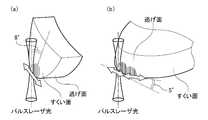
図1(a)および図1(b)は、非特許文献1に記載された、パルスレーザ研削によりダイヤモンドコーティング工具の刃先を鋭利化する方法を説明するための図である。図1(a)は、すくい面側をパルスレーザ研削する様子を示し、図1(b)は、逃げ面側を2方向にパルスレーザ研削する様子を示す。パルスレーザ研削を利用すると、工具刃先に対してレーザ光をわずかに切り込ませ、その状態で刃先稜線に沿った送り運動をレーザ光と工具の間に与えることで、刃先の鋭利化を行うことができる。1 (a) and 1 (b) are diagrams for explaining a method of sharpening the cutting edge of a diamond coating tool by pulse laser grinding described in Non-Patent
現在のところ、レーザ光が工具刃先に切り込んだことを検出する技術が開発されていないため、レーザ研削を自動化するには至っていない。現状では、わずかな切込み時に発生するプラズマを作業者が目視またはカメラの撮影画像を利用して視認することで、レーザ光が工具刃先に当たったことを確認している。そこでレーザ研削加工において、レーザ光と被加工部材との相対位置関係を特定する技術の開発が望まれている。またレーザ研削加工を監視する技術の開発も望まれている。At present, the technology for detecting that the laser beam has cut into the tool edge has not been developed, so laser grinding has not been automated yet. At present, it is confirmed that the laser beam hits the tool edge by the operator visually observing the plasma generated at the time of a slight cut or by using the image taken by the camera. Therefore, in laser grinding, it is desired to develop a technique for specifying the relative positional relationship between the laser beam and the member to be processed. It is also desired to develop a technique for monitoring laser grinding.
本開示はこうした状況に鑑みてなされており、その目的とするところの1つは、レーザ研削加工において、レーザ光と被加工部材との相対位置関係を特定する技術を提供することにある。また本開示の目的の1つは、レーザ研削加工を監視する技術を提供することにある。The present disclosure has been made in view of such a situation, and one of the purposes thereof is to provide a technique for specifying the relative positional relationship between the laser beam and the member to be processed in the laser grinding process. Another object of the present disclosure is to provide a technique for monitoring laser grinding.
上記課題を解決するために、本開示のある態様の加工装置は、レーザ光の集束箇所を含む筒状照射領域を走査して、被加工部材を加工する加工装置であって、被加工部材をレーザ光の筒状照射領域に対して相対移動させる送り機構と、被加工部材に照射されなかったレーザ光を受光する受光部と、受光したレーザ光の強度を検出する強度検出部と、検出した光強度にもとづいて、レーザ光と被加工部材との相対位置関係を特定する制御部とを備える。In order to solve the above problems, the processing apparatus according to the present disclosure is a processing apparatus that scans a tubular irradiation region including a focused portion of laser light to process a member to be processed, and processes the member to be processed. A feeding mechanism that moves the laser light relative to the tubular irradiation region, a light receiving unit that receives the laser light that was not irradiated to the member to be processed, and an intensity detecting unit that detects the intensity of the received laser light were detected. It is provided with a control unit that specifies the relative positional relationship between the laser beam and the member to be processed based on the light intensity.
本開示の別の態様の加工装置は、レーザ光の集束箇所を含む筒状照射領域を走査して、被加工部材を加工する加工装置であって、被加工部材をレーザ光の筒状照射領域に対して相対移動させる送り機構と、被加工部材に照射されなかったレーザ光を受光する受光部と、受光したレーザ光の強度を検出する強度検出部と、検出した光強度にもとづいて、被加工部材の加工に利用されているレーザ光の量を特定する制御部とを備える。The processing apparatus of another aspect of the present disclosure is a processing apparatus for processing a member to be processed by scanning a tubular irradiation region including a focused portion of laser light, and the member to be processed is subjected to a tubular irradiation region of laser light. Based on the feed mechanism that moves relative to the member, the light receiving unit that receives the laser light that was not applied to the member to be processed, the intensity detection unit that detects the intensity of the received laser light, and the detected light intensity. It is provided with a control unit that specifies the amount of laser light used for processing the processed member.
本開示の別の態様は、レーザ光の集束箇所を含む筒状照射領域を走査して、被加工部材を加工する加工装置において、レーザ光と被加工部材との相対位置関係を特定する方法であって、被加工部材をレーザ光の筒状照射領域に対して相対移動させるステップと、被加工部材に照射されなかったレーザ光を受光するステップと、受光したレーザ光の強度を検出するステップと、検出した光強度にもとづいて、レーザ光と被加工部材との相対位置関係を特定するステップとを備える。Another aspect of the present disclosure is a method of scanning a tubular irradiation region including a focused portion of laser light to specify a relative positional relationship between the laser light and the member to be processed in a processing apparatus for processing the member to be processed. There are a step of moving the member to be processed relative to the tubular irradiation region of the laser beam, a step of receiving the laser beam not irradiated to the member to be processed, and a step of detecting the intensity of the received laser beam. The step includes a step of specifying the relative positional relationship between the laser beam and the member to be processed based on the detected light intensity.
本開示の別の態様は、レーザ光の集束箇所を含む筒状照射領域を走査して、被加工部材を加工する加工装置において、レーザ光と被加工部材との相対位置関係を特定する方法であって、被加工部材をレーザ光の筒状照射領域に対して相対移動させるステップと、被加工部材に照射されなかったレーザ光を受光するステップと、受光したレーザ光の強度を検出するステップと、検出した光強度にもとづいて、被加工部材の加工に利用されているレーザ光の量を特定するステップとを備える。Another aspect of the present disclosure is a method of scanning a tubular irradiation region including a focused portion of laser light to specify a relative positional relationship between the laser light and the member to be processed in a processing apparatus for processing the member to be processed. There are a step of moving the member to be processed relative to the tubular irradiation region of the laser beam, a step of receiving the laser beam not irradiated to the member to be processed, and a step of detecting the intensity of the received laser beam. The step includes a step of specifying the amount of laser light used for processing the member to be processed based on the detected light intensity.
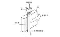
図2は、パルスレーザ研削を説明するための図である。パルスレーザ研削は、特許文献1および非特許文献1に開示されるように、レーザ光2の光軸方向に延び且つ加工可能なエネルギをもつ円筒状の照射領域を被加工部材20の表面に重ねて、その光軸と交差する方向へ走査することで、円筒状の照射領域が通過した被加工部材20の表面領域を除去する加工法である。パルスレーザ研削は、被加工部材20の表面に、光軸方向および走査方向に平行な面を成形する。FIG. 2 is a diagram for explaining pulse laser grinding. In pulse laser grinding, as disclosed in
図3は、パルスレーザ研削を行うレーザ加工装置1の概略構成を示す。レーザ加工装置1は、レーザ光2を出射するレーザ光照射部10、被加工部材20を支持する支持装置14、レーザ光照射部10の被加工部材20に対する相対的な移動を可能とする案内機構11、案内機構11に沿って所定の移動を実現するためのアクチュエータ12、およびレーザ加工装置1の全体の動作を制御する制御部13を備える。案内機構11およびアクチュエータ12は、被加工部材20をレーザ光2の筒状照射領域に対して相対移動させる送り機構を構成する。実施形態において被加工部材20は切削工具であって、レーザ加工装置1は、切削工具の刃先を先鋭化するパルスレーザ研削を行うが、被加工部材20は他の種類の部材であってもよい。FIG. 3 shows a schematic configuration of a
レーザ光照射部10は、レーザ光を発生するレーザ発振器、レーザ光の出力を調整する減衰器、レーザ光の向きを変えるミラーなどを備え、これらを経たレーザ光2が光学レンズ経由で集光され、出射されるように構成される。たとえばレーザ発振器は、Nd:YAGパルスレーザ光を発生してよい。The laser
実施形態の送り機構は、被加工部材20に対するレーザ光照射部10の相対的な位置を変化させるものであって、相対的な姿勢を変化させるための機構も有してよい。アクチュエータ12は、制御部13からの指令に応じて所望の相対移動を行い、これにより被加工部材20に対するレーザ光照射部10の相対位置、さらに必要に応じて相対姿勢を変化させる。なお図3に示すレーザ加工装置1では、案内機構11がレーザ光照射部10の位置、さらに必要に応じて姿勢を変化させるが、レーザ光照射部10を固定することが好ましい場合は、支持装置14の位置、さらに必要に応じて姿勢を変化させてよい。いずれにしても送り機構は、被加工部材20を、レーザ光2の筒状照射領域に対して相対的に移動させ、また必要に応じて相対的に姿勢変化させるための機構を有する。The feed mechanism of the embodiment changes the relative position of the laser
実施形態のレーザ加工装置1は、レーザ光照射部10より出射されて、被加工部材20を通過し、被加工部材20に照射されなかったレーザ光を受光する受光部16を備える。受光部16はレーザ光照射口に対向して、所定距離だけ離れた位置に配置される。送り機構によってレーザ光照射部10が動かされる場合、受光部16はレーザ光照射部10との相対位置関係を維持しながら、レーザ光照射部10とともに動かされる。The
パルスレーザ研削は被加工部材20の表面に、レーザ光2の光軸方向および走査方向に平行な面を成形する加工法であるため、レーザ光2の一部のみが被加工部材20の材料除去に利用され、レーザ光2の大部分は被加工部材20を照射せずに通過する。そこで実施形態の受光部16は、被加工部材20の加工に利用されずに通過したレーザ光2を受光する。強度検出部18は、受光部16が受光したレーザ光の強度を検出する。受光部16および強度検出部18は、別体として設けられてよいが、一体として設けられてもよい。Since pulse laser grinding is a processing method in which a surface parallel to the optical axis direction and the scanning direction of the
パルスレーザ研削に利用されるレーザ光2は、被加工部材20の付近で集束するように出射されるため、被加工部材20の付近で最も高いエネルギ密度をもつ。受光部16の破損および劣化を防ぐため、受光部16は、集束した筒状照射領域から、ある程度離れた位置に設置されることが好ましい。たとえばレーザ光照射部10のレーザ光を集光する光学レンズから被加工部材20までの距離Lに対して、被加工部材20から受光部16までの距離は、L以上すなわち同程度以上に設定されることが好ましい。Since the
レーザ加工装置1は、レーザ光2の筒状照射領域を被加工部材20に対して徐々に切り込む(食い込む)ように移動させる際に、切り込み始める瞬間の相対位置(原点)を正確に特定することで、被加工部材20に対して正確な除去量(切込み量)の加工を実現できる。そこで実施形態のレーザ加工装置1は、パルスレーザ研削を行う前に、強度検出部18が検出した光強度にもとづいて、レーザ光2が被加工部材20に切り込み始める瞬間の相対位置を特定する機能(原点設定機能)を備える。When the
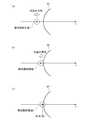
図4(a)~(c)は、レーザ加工装置1における原点設定処理を説明するための図である。図4(a)~(c)は、送り機構がレーザ光2を被加工部材20に切り込む方向(近づける方向)に移動させる様子を示すが、実際には被加工部材20をレーザ光2に近づける方向に移動させてよい。ここでは送り方向をx軸正方向とし、移動速度vを一定とする。4 (a) to 4 (c) are diagrams for explaining the origin setting process in the
図4(a)は、レーザ光2の光軸中心のx座標が初期位置x0にある状態を示す。この状態から、送り機構がレーザ光2を切込み方向に一定速度vで動かす。図4(b)は、レーザ光2の筒状照射領域の最外周部分が被加工部材20に当たった瞬間、すなわち切り込み始めた瞬間の状態を示す。このときのレーザ光軸中心のx座標はx1である。送り機構が引き続きレーザ光2を一定速度vで動かすと、レーザ光2の一部分が被加工部材20を照射する。図4(c)は、レーザ光2の筒状照射領域の一部分が被加工部材20を照射しているときの状態を示す。このときのレーザ光軸中心のx座標はx2である。FIG. 4A shows a state in which the x coordinate of the center of the optical axis of the
実施形態の制御部13は、レーザ光2の筒状照射領域が被加工部材20に切り込み始めたときの座標x1を原点座標として特定することで、その後のレーザパルス研削の切込み量を正確に設定できる。The control unit 13 of the embodiment specifies the coordinates x 1 when the cylindrical irradiation region of the
図5(a)は、送り量の時間変化を示す。図5(a)には、時間t0から時間t2までの間、光軸中心がx0からx2まで一定速度で動かされて、その後移動を停止されたレーザ光2の送り動作が示される。FIG. 5A shows the time change of the feed amount. In FIG. 5 (a), during the time t0 to time t2, and the optical axis center is moved at a constant speed from x0 to x2, then moved to stop the feeding operation of the
図5(b)は、強度検出部18が検出する光強度の時間変化を示す。制御部13は、強度検出部18が検出する光強度を監視する。図4(a)および図4(b)に示されるように、光軸中心がx0からx1まで移動する間(つまり時間t0から時間t1までの間)、筒状照射領域は被加工部材20に切り込まない、つまり当たらないため、強度検出部18が検出する光強度は、基準値である初期値I0から変化しない。制御部13は、光強度が初期値I0で一定である場合に、レーザ光2が被加工部材20に切り込んでいないことを判定する。FIG. 5B shows the time change of the light intensity detected by the
時間t1でレーザ光2の筒状照射領域の最外周部分が被加工部材20に切り込み始めると、被加工部材20に切り込んだ(入り込んだ)レーザ光のエネルギは被加工部材20の加工に利用されるため、強度検出部18が検出する光強度は減少する。制御部13は、強度検出部18が検出した光強度が初期値I0から減少するタイミングで、レーザ光照射部10から出射されるレーザ光2が被加工部材20に切り込み始めたことを判定する。この例では、時間t1のタイミングで、つまりはx軸において光軸中心のx座標がx1になったときに、制御部13は、筒状照射領域の最外周部分が被加工部材20に切り込み始めたことを特定する。この特定処理は、いわゆる原点設定処理に相当し、制御部13は、x1の座標値を基準として、その後のパルスレーザ研削の切込み量を正確に設定できる。When the outermost peripheral portion of the tubular irradiation region of the
なお図5(a)に示す送り動作例では、送り機構が、レーザ光2の光軸中心をx2まで移動して停止している。図5(b)に示すように、時間t1から時間t2までの間、レーザ光2が被加工部材20を照射する面積が増えることで、強度検出部18が検出する光強度は徐々に減少する。基準値である初期値I0からの光強度減少分は、被加工部材20の加工に利用されているレーザ光の量に対応し、このレーザ光量は、被加工部材20の材料除去に利用されているエネルギに対応する。したがって制御部13は、初期値I0からの光強度減少分を監視することで、被加工部材20の加工に利用されているレーザ光の量を特定し、現在加工中の被加工部材20の除去面積を推定できる。In still feed operation example shown in FIG. 5 (a), the feed mechanism is stopped by moving the optical axis of the
被加工部材20の除去面積を推定する際、強度検出部18がレーザ光強度の変動を監視し、制御部13が、被加工部材20に向けて出射される光強度の変動分を加味して、加工に利用されているレーザ光の量を特定してよい。たとえば強度検出部18は、光強度変動の監視用に、レーザ光2の一部を分岐して光強度を常時監視する。制御部13は、光強度の監視結果から光強度の変動割合を算出し、変動割合を用いて被加工部材20に向けて出射される光強度の瞬時値I0を算出して、出射光強度I0からの光強度減少分を監視することで、被加工部材20の加工に利用されているレーザ光の量を特定してよい。これにより被加工部材20の除去面積をより正確に推定できるようになる。When estimating the removal area of the
一方、時間t2から時間t3までの間、強度検出部18が検出する光強度は徐々に増加してI0に近い値に復帰する。時間t2でレーザ光2の送り動作が停止されると(図4(c)に示す状態)、レーザ光2による材料除去がレーザ光2の進行方向に進み、材料が除去されて被加工部材20を通過(貫通)するレーザ光が増え、強度検出部18が検出する光強度は徐々に増加する。なお原点設定処理のためには、光強度が減少する時間t1さえ分かればよいため、制御部13は、時間t1におけるx座標(x1)を特定した時点で、送り機構の動作を停止させてよい。On the other hand, during the periodfrom time t 2 to time t3 , the light intensity detected by the
加工対象となる被加工部材20の切れ刃が円弧形状を有する場合、原点設定処理は、被加工部材20の切れ刃稜線に沿って複数の点で、または連続的に実施されることが好ましい。レーザ光2と切れ刃稜線の間の原点設定を複数の点で行うことで、レーザ光2と被加工部材20の切れ刃稜線との相対位置関係を同定することができ、レーザ加工装置1が高精度な刃先加工を実現できるようになる。なお、原点設定処理の点数が2つ以上の場合には切れ刃稜線の傾きを同定することができ、3つ以上の場合には円弧形状の切れ刃稜線に対してその相対的な中心位置と半径を同定することができる。When the cutting edge of the
原点設定処理において制御部13は、レーザ光照射部10が出力するレーザ光2の強度を、レーザ光2が被加工部材20を加工するレベルよりも低く設定してよい。原点設定処理時のレーザ光強度を加工レベルよりも低く設定することで、レーザ光2が被加工部材20を加工しないため、強度検出部18が、送り速度に依存することなく、被加工部材20に照射されなかったレーザ光の強度を正確に測定できる。これにより制御部13は原点の座標値を正確に導出でき、原点座標値を用いた高精度なレーザパルス研削を実行できる。原点設定処理に際して、制御部13は、レーザ光照射部10が出力するレーザ光2の強度を、被加工部材20に熱的な損傷を与えない程度に十分低く設定してもよい。In the origin setting process, the
図6(a)は、パルスレーザ研削の様子の一例を示す。制御部13は、複数の点で原点設定処理を行った後、被加工部材20の切れ刃稜線を特定し、特定した切れ刃稜線に沿って刃先を加工する。図6(a)に示す例では、被加工部材20の刃先に対してΔxだけ筒状照射領域を入り込ませ、筒状照射領域を切れ刃稜線に沿って一定の送り速度で移動させる。FIG. 6A shows an example of the state of pulse laser grinding. The
図6(b)は、パルスレーザ研削中の光強度の時間変化を示す。レーザ加工装置1が、一定の送り速度で刃先加工する場合、筒状照射領域の進入量(Δx)が刃先稜線に沿って一定であり、レーザ光軸方向の被加工部材厚さが各進入深さ位置で一定であれば、強度検出部18が検出する光強度は一定となる。この状態が、実線で示される。一方で、進入量が刃先稜線に沿って次第に小さくなる(進入不足)と、強度検出部18が検出する光強度は次第に大きくなり、進入量が刃先稜線に沿って次第に大きくなる(進入し過ぎ)と、強度検出部18が検出する光強度は次第に小さくなる。このように制御部13は、パルスレーザ研削時の光強度を監視することで、パルスレーザ研削が適切に実施されているか判断できる。なお光強度の監視中に、突然光強度が大きくなった場合、制御部13は、刃先に欠損が生じていることを判定してよい。FIG. 6B shows the time change of the light intensity during pulse laser grinding. When the
以上、本開示を実施例をもとに説明した。この実施例は例示であり、それらの各構成要素や各処理プロセスの組合せにいろいろな変形例が可能なこと、またそうした変形例も本開示の範囲にあることは当業者に理解されるところである。The present disclosure has been described above based on the examples. This embodiment is an example, and it will be understood by those skilled in the art that various modifications are possible for each of these components and combinations of each processing process, and that such modifications are also within the scope of the present disclosure. ..
本開示の態様の概要は、次の通りである。本開示のある態様は、レーザ光の集束箇所を含む筒状照射領域を走査して、被加工部材を加工する加工装置であって、被加工部材をレーザ光の筒状照射領域に対して相対移動させる送り機構と、被加工部材に照射されなかったレーザ光を受光する受光部と、受光したレーザ光の強度を検出する強度検出部と、検出した光強度にもとづいて、レーザ光と被加工部材との相対位置関係を特定する制御部とを備える。The outline of the aspect of the present disclosure is as follows. One aspect of the present disclosure is a processing apparatus for processing a member to be processed by scanning a tubular irradiation region including a focused portion of laser light, and the member to be processed is relative to the tubular irradiation region of laser light. The feed mechanism to move, the light receiving part that receives the laser light that was not applied to the member to be processed, the intensity detection part that detects the intensity of the received laser light, and the laser light and the work to be processed based on the detected light intensity. It is provided with a control unit that specifies a relative positional relationship with the member.
パルスレーザ研削では被加工部材の材料除去に利用されないレーザ光が、被加工部材を照射せずに通過することを利用して、制御部は、通過したレーザ光の強度にもとづいて、レーザ光と被加工部材との相対位置関係を特定できる。たとえばレーザ光が被加工部材に入り込んでいないときの光強度をI0とすると、送り機構が被加工部材をレーザ光の筒状照射領域に対して近づけても光強度がI0で変化しなければ、制御部は、レーザ光が被加工部材に当たっていないことを判定してよい。Utilizing the fact that laser light, which is not used for removing the material of the member to be processed in pulse laser grinding, passes through without irradiating the member to be processed, the control unit uses the laser light based on the intensity of the passed laser light. The relative positional relationship with the member to be machined can be specified. For example, the light intensity when the laser light is not penetrated into the workpiece and I0, also feed mechanism is closer to the workpiece with respect to the tubular irradiation region of the laser beam have a light intensity changes in I0 For example, the control unit may determine that the laser beam does not hit the member to be processed.
制御部は、検出した光強度が減少するタイミングで、レーザ光が被加工部材に切り込み始めたことを判定してよい。相対位置関係を特定する際、制御部は、レーザ光の強度を、レーザ光が被加工部材を加工するレベルよりも低く設定してよい。制御部は、レーザ光と被加工部材の切れ刃稜線の相対位置関係を特定してもよい。The control unit may determine that the laser beam has begun to cut into the member to be processed at the timing when the detected light intensity decreases. When specifying the relative positional relationship, the control unit may set the intensity of the laser beam to be lower than the level at which the laser beam processes the member to be processed. The control unit may specify the relative positional relationship between the laser beam and the cutting edge ridgeline of the member to be processed.
本開示の別の態様は、レーザ光の集束箇所を含む筒状照射領域を走査して、被加工部材を加工する加工装置であって、被加工部材をレーザ光の筒状照射領域に対して相対移動させる送り機構と、被加工部材に照射されなかったレーザ光を受光する受光部と、受光したレーザ光の強度を検出する強度検出部と、検出した光強度にもとづいて、被加工部材の加工に利用されているレーザ光の量を特定する制御部とを備える。Another aspect of the present disclosure is a processing apparatus for processing a member to be processed by scanning a tubular irradiation region including a focused portion of laser light, and the member to be processed is applied to a tubular irradiation region of laser light. A feed mechanism that moves relative to each other, a light receiving unit that receives laser light that has not been applied to the member to be processed, an intensity detection unit that detects the intensity of the received laser light, and a member to be processed based on the detected light intensity. It is provided with a control unit that specifies the amount of laser light used for processing.
制御部は、被加工部材の加工に利用されているレーザ光の量を特定することで、被加工部材の加工状況を監視することが可能となる。The control unit can monitor the processing status of the member to be processed by specifying the amount of laser light used for processing the member to be processed.
本開示の別の態様は、レーザ光の集束箇所を含む筒状照射領域を走査して、被加工部材を加工する加工装置において、レーザ光と被加工部材との相対位置関係を特定する方法であって、被加工部材をレーザ光の筒状照射領域に対して相対移動させるステップと、被加工部材に照射されなかったレーザ光を受光するステップと、受光したレーザ光の強度を検出するステップと、検出した光強度にもとづいて、レーザ光と被加工部材との相対位置関係を特定するステップとを備える。Another aspect of the present disclosure is a method of scanning a tubular irradiation region including a focused portion of laser light to specify a relative positional relationship between the laser light and the member to be processed in a processing apparatus for processing the member to be processed. There are a step of moving the member to be processed relative to the tubular irradiation region of the laser beam, a step of receiving the laser beam not irradiated to the member to be processed, and a step of detecting the intensity of the received laser beam. The step includes a step of specifying the relative positional relationship between the laser beam and the member to be processed based on the detected light intensity.
本開示の別の態様は、レーザ光の集束箇所を含む筒状照射領域を走査して、被加工部材を加工する加工装置において、レーザ光と被加工部材との相対位置関係を特定する方法であって、被加工部材をレーザ光の筒状照射領域に対して相対移動させるステップと、被加工部材に照射されなかったレーザ光を受光するステップと、受光したレーザ光の強度を検出するステップと、検出した光強度にもとづいて、被加工部材の加工に利用されているレーザ光の量を特定するステップとを備える。Another aspect of the present disclosure is a method of scanning a tubular irradiation region including a focused portion of laser light to specify a relative positional relationship between the laser light and the member to be processed in a processing apparatus for processing the member to be processed. There are a step of moving the member to be processed relative to the tubular irradiation region of the laser beam, a step of receiving the laser beam not irradiated to the member to be processed, and a step of detecting the intensity of the received laser beam. The step includes a step of specifying the amount of laser light used for processing the member to be processed based on the detected light intensity.
本開示は、パルスレーザ研削の加工装置において利用できる。The present disclosure can be used in a processing apparatus for pulse laser grinding.
1・・・レーザ加工装置、2・・・レーザ光、10・・・レーザ光照射部、11・・・案内機構、12・・・アクチュエータ、13・・・制御部、14・・・支持装置、16・・・受光部、18・・・強度検出部、20・・・被加工部材。1 ... Laser processing device, 2 ... Laser light, 10 ... Laser light irradiation unit, 11 ... Guide mechanism, 12 ... Actuator, 13 ... Control unit, 14 ... Support device , 16 ... Light receiving part, 18 ... Strength detection part, 20 ... Member to be machined.
Claims (7)
Translated fromJapanese被加工部材をレーザ光の筒状照射領域に対して相対移動させる送り機構と、
被加工部材に照射されなかったレーザ光を受光する受光部と、
受光したレーザ光の強度を検出する強度検出部と、
検出した光強度にもとづいて、レーザ光と被加工部材との相対位置関係を特定する制御部と、
を備える加工装置。A processing device that processes a member to be processed by scanning a cylindrical irradiation region including a focused portion of laser light.
A feed mechanism that moves the member to be processed relative to the cylindrical irradiation region of the laser beam,
A light receiving part that receives laser light that was not applied to the member to be processed,
An intensity detector that detects the intensity of the received laser beam,
A control unit that identifies the relative positional relationship between the laser beam and the member to be processed based on the detected light intensity.
A processing device equipped with.
ことを特徴とする請求項1に記載の加工装置。The control unit sets the intensity of the laser beam to be lower than the level at which the laser beam processes the member to be processed.
The processing apparatus according to claim 1.
ことを特徴とする請求項1または2に記載の加工装置。The control unit specifies the relative positional relationship between the laser beam and the cutting edge ridgeline of the member to be processed.
The processing apparatus according to claim 1 or 2.
被加工部材をレーザ光の筒状照射領域に対して相対移動させる送り機構と、
被加工部材に照射されなかったレーザ光を受光する受光部と、
受光したレーザ光の強度を検出する強度検出部と、
検出した光強度にもとづいて、被加工部材の加工に利用されているレーザ光の量を特定する制御部と、
を備える加工装置。A processing device that processes a member to be processed by scanning a cylindrical irradiation region including a focused portion of laser light.
A feed mechanism that moves the member to be processed relative to the cylindrical irradiation region of the laser beam,
A light receiving part that receives laser light that was not applied to the member to be processed,
An intensity detector that detects the intensity of the received laser beam,
A control unit that specifies the amount of laser light used to process the member to be processed based on the detected light intensity.
A processing device equipped with.
ことを特徴とする請求項1から4のいずれかに記載の加工装置。The control unit determines that the laser beam has begun to cut into the member to be processed at the timing when the detected light intensity decreases.
The processing apparatus according to any one of claims 1 to 4.
被加工部材をレーザ光の筒状照射領域に対して相対移動させるステップと、
被加工部材に照射されなかったレーザ光を受光するステップと、
受光したレーザ光の強度を検出するステップと、
検出した光強度にもとづいて、レーザ光と被加工部材との相対位置関係を特定するステップと、
を備える相対位置関係特定方法。A method of identifying a relative positional relationship between a laser beam and a member to be processed in a processing apparatus for processing a member to be processed by scanning a cylindrical irradiation region including a focused portion of the laser beam.
A step of moving the member to be processed relative to the cylindrical irradiation region of the laser beam,
The step of receiving the laser beam that was not applied to the member to be processed,
The step of detecting the intensity of the received laser beam and
A step to specify the relative positional relationship between the laser beam and the member to be processed based on the detected light intensity,
A method for identifying a relative positional relationship.
被加工部材をレーザ光の筒状照射領域に対して相対移動させるステップと、
被加工部材に照射されなかったレーザ光を受光するステップと、
受光したレーザ光の強度を検出するステップと、
検出した光強度にもとづいて、被加工部材の加工に利用されているレーザ光の量を特定するステップと、
を備えるレーザ光量特定方法。A method of identifying a relative positional relationship between a laser beam and a member to be processed in a processing apparatus for processing a member to be processed by scanning a cylindrical irradiation region including a focused portion of the laser beam.
A step of moving the member to be processed relative to the cylindrical irradiation region of the laser beam,
The step of receiving the laser beam that was not applied to the member to be processed,
The step of detecting the intensity of the received laser beam and
A step to specify the amount of laser light used for processing the member to be processed based on the detected light intensity, and
A method for specifying the amount of laser light.
Priority Applications (4)
| Application Number | Priority Date | Filing Date | Title |
|---|---|---|---|
| JP2021511010AJP6963345B1 (en) | 2020-03-30 | 2020-03-30 | Processing equipment, relative positional relationship identification method and laser light intensity identification method |
| PCT/JP2020/014710WO2021199222A1 (en) | 2020-03-30 | 2020-03-30 | Processing device, relative positional relationship identification method, and laser light quantity identification method |
| CN202080095279.XACN115038545A (en) | 2020-03-30 | 2020-03-30 | Processing device, relative positional relationship specifying method, and laser light quantity specifying method |
| US17/196,441US20210299792A1 (en) | 2020-03-30 | 2021-03-09 | Machining apparatus, method for identifying relative positional relationship, and method for determining laser light quantity |
Applications Claiming Priority (1)
| Application Number | Priority Date | Filing Date | Title |
|---|---|---|---|
| PCT/JP2020/014710WO2021199222A1 (en) | 2020-03-30 | 2020-03-30 | Processing device, relative positional relationship identification method, and laser light quantity identification method |
Related Child Applications (1)
| Application Number | Title | Priority Date | Filing Date |
|---|---|---|---|
| US17/196,441ContinuationUS20210299792A1 (en) | 2020-03-30 | 2021-03-09 | Machining apparatus, method for identifying relative positional relationship, and method for determining laser light quantity |
Publications (1)
| Publication Number | Publication Date |
|---|---|
| WO2021199222A1true WO2021199222A1 (en) | 2021-10-07 |
Family
ID=77857332
Family Applications (1)
| Application Number | Title | Priority Date | Filing Date |
|---|---|---|---|
| PCT/JP2020/014710CeasedWO2021199222A1 (en) | 2020-03-30 | 2020-03-30 | Processing device, relative positional relationship identification method, and laser light quantity identification method |
Country Status (4)
| Country | Link |
|---|---|
| US (1) | US20210299792A1 (en) |
| JP (1) | JP6963345B1 (en) |
| CN (1) | CN115038545A (en) |
| WO (1) | WO2021199222A1 (en) |
Citations (3)
| Publication number | Priority date | Publication date | Assignee | Title |
|---|---|---|---|---|
| JP2003025118A (en)* | 2001-07-13 | 2003-01-29 | Allied Material Corp | Diamond tool for cutting |
| JP2013022676A (en)* | 2011-07-20 | 2013-02-04 | Canon Inc | Device for detecting deflection amount of laser light, device for measuring displacement, method of manufacturing optical element molding die and optical element |
| JP2016159318A (en)* | 2015-02-27 | 2016-09-05 | 国立大学法人 名古屋工業大学 | Laser processing apparatus, control apparatus and processing surface forming method |
Family Cites Families (6)
| Publication number | Priority date | Publication date | Assignee | Title |
|---|---|---|---|---|
| JPS61189885A (en)* | 1985-02-18 | 1986-08-23 | ジエロ−ム、エツチ、レメルソン | Method of forming cutting edge and method and device for improving cutting edge |
| GB0603653D0 (en)* | 2006-02-24 | 2006-04-05 | Renishaw Plc | Tool detection |
| KR101338509B1 (en)* | 2012-02-28 | 2013-12-10 | 국립대학법인 울산과학기술대학교 산학협력단 | Method for setting referece point of tool position |
| CN104551863A (en)* | 2013-10-29 | 2015-04-29 | 常州昊锐工具有限公司 | A tool diameter detection device |
| CN206105624U (en)* | 2016-11-03 | 2017-04-19 | 凯瑞恩智能科技(苏州)有限公司 | Grinding wheel wear is automatic to be detected and compensation arrangement |
| DE102017105955A1 (en)* | 2017-03-20 | 2018-09-20 | Laserpluss Ag | Laser grinding device and method for processing a workpiece |
- 2020
- 2020-03-30CNCN202080095279.XApatent/CN115038545A/enactivePending
- 2020-03-30JPJP2021511010Apatent/JP6963345B1/enactiveActive
- 2020-03-30WOPCT/JP2020/014710patent/WO2021199222A1/ennot_activeCeased
- 2021
- 2021-03-09USUS17/196,441patent/US20210299792A1/ennot_activeAbandoned
Patent Citations (3)
| Publication number | Priority date | Publication date | Assignee | Title |
|---|---|---|---|---|
| JP2003025118A (en)* | 2001-07-13 | 2003-01-29 | Allied Material Corp | Diamond tool for cutting |
| JP2013022676A (en)* | 2011-07-20 | 2013-02-04 | Canon Inc | Device for detecting deflection amount of laser light, device for measuring displacement, method of manufacturing optical element molding die and optical element |
| JP2016159318A (en)* | 2015-02-27 | 2016-09-05 | 国立大学法人 名古屋工業大学 | Laser processing apparatus, control apparatus and processing surface forming method |
Also Published As
| Publication number | Publication date |
|---|---|
| JP6963345B1 (en) | 2021-11-05 |
| JPWO2021199222A1 (en) | 2021-10-07 |
| CN115038545A (en) | 2022-09-09 |
| US20210299792A1 (en) | 2021-09-30 |
Similar Documents
| Publication | Publication Date | Title |
|---|---|---|
| CN109079328B (en) | Method for machining a workpiece by means of a laser beam, laser tool, laser machining machine, and machine control | |
| CN110248765B (en) | Method for machining cutting inserts and corresponding apparatus for machining cutting inserts | |
| US10549382B2 (en) | Laser-assisted micromachining systems and methods | |
| CN110587123A (en) | Laser processing device and processing method thereof | |
| JPS61123493A (en) | Laser working device | |
| JPH07284974A (en) | Laser processing method and apparatus | |
| CN110238544B (en) | Laser thinning method and laser machine | |
| CA2827468A1 (en) | Method and apparatus for machining a workpiece by means of a laser beam | |
| JP5201424B2 (en) | Carbon film coated cutting tool and method for manufacturing the same | |
| CN115213568A (en) | A composite laser processing system and processing method | |
| US20210402520A1 (en) | Method for the material-removing laser machining of a workpiece | |
| JP6963345B1 (en) | Processing equipment, relative positional relationship identification method and laser light intensity identification method | |
| JP6441731B2 (en) | Laser processing equipment | |
| US20200379433A1 (en) | Numerical control device and machine tool | |
| CN110834151A (en) | Laser processing control method, laser processing apparatus, and computer-readable storage medium | |
| JP2006218535A (en) | Laser machining method and laser machining apparatus | |
| JP7460199B2 (en) | Processing equipment and processing end detection method | |
| CN113747997B (en) | Tool tip processing device and cutting device | |
| JP2016147272A (en) | Laser processing method and laser processing machine | |
| KR102349328B1 (en) | Laser assisted micro-machining system and method for micro-machining using the same | |
| JP7320889B2 (en) | Laser processing method | |
| Giedl‐Wagner et al. | X‐ray emissions during laser machining of cylindrical micro‐components: Innovative laser ‘turning’operations for the manufacture of precision components | |
| JP7098211B1 (en) | Laser machining equipment, thickness detection method and thickness detection equipment | |
| CN110834146A (en) | Laser processing control method, laser processing apparatus, and computer-readable storage medium | |
| WO2025173059A1 (en) | Laser processing machine |
Legal Events
| Date | Code | Title | Description |
|---|---|---|---|
| ENP | Entry into the national phase | Ref document number:2021511010 Country of ref document:JP Kind code of ref document:A | |
| 121 | Ep: the epo has been informed by wipo that ep was designated in this application | Ref document number:20928615 Country of ref document:EP Kind code of ref document:A1 | |
| NENP | Non-entry into the national phase | Ref country code:DE | |
| 122 | Ep: pct application non-entry in european phase | Ref document number:20928615 Country of ref document:EP Kind code of ref document:A1 |