WO2021193238A1 - Information processing device, information processing method, and program - Google Patents
Information processing device, information processing method, and programDownload PDFInfo
- Publication number
- WO2021193238A1 WO2021193238A1PCT/JP2021/010620JP2021010620WWO2021193238A1WO 2021193238 A1WO2021193238 A1WO 2021193238A1JP 2021010620 WJP2021010620 WJP 2021010620WWO 2021193238 A1WO2021193238 A1WO 2021193238A1
- Authority
- WO
- WIPO (PCT)
- Prior art keywords
- image
- information
- visible light
- infrared
- pixel
- Prior art date
- Legal status (The legal status is an assumption and is not a legal conclusion. Google has not performed a legal analysis and makes no representation as to the accuracy of the status listed.)
- Ceased
Links
Images


Classifications
- G—PHYSICS
- G06—COMPUTING OR CALCULATING; COUNTING
- G06T—IMAGE DATA PROCESSING OR GENERATION, IN GENERAL
- G06T7/00—Image analysis
- G06T7/50—Depth or shape recovery
- G06T7/55—Depth or shape recovery from multiple images
- G06T7/593—Depth or shape recovery from multiple images from stereo images
- G—PHYSICS
- G06—COMPUTING OR CALCULATING; COUNTING
- G06T—IMAGE DATA PROCESSING OR GENERATION, IN GENERAL
- G06T5/00—Image enhancement or restoration
- G06T5/50—Image enhancement or restoration using two or more images, e.g. averaging or subtraction
- G—PHYSICS
- G06—COMPUTING OR CALCULATING; COUNTING
- G06T—IMAGE DATA PROCESSING OR GENERATION, IN GENERAL
- G06T7/00—Image analysis
- G06T7/50—Depth or shape recovery
- G06T7/521—Depth or shape recovery from laser ranging, e.g. using interferometry; from the projection of structured light
- G—PHYSICS
- G06—COMPUTING OR CALCULATING; COUNTING
- G06T—IMAGE DATA PROCESSING OR GENERATION, IN GENERAL
- G06T7/00—Image analysis
- G06T7/50—Depth or shape recovery
- G06T7/55—Depth or shape recovery from multiple images
- G06T7/579—Depth or shape recovery from multiple images from motion
- G—PHYSICS
- G06—COMPUTING OR CALCULATING; COUNTING
- G06V—IMAGE OR VIDEO RECOGNITION OR UNDERSTANDING
- G06V10/00—Arrangements for image or video recognition or understanding
- G06V10/10—Image acquisition
- G06V10/12—Details of acquisition arrangements; Constructional details thereof
- G06V10/14—Optical characteristics of the device performing the acquisition or on the illumination arrangements
- G06V10/143—Sensing or illuminating at different wavelengths
- G—PHYSICS
- G06—COMPUTING OR CALCULATING; COUNTING
- G06V—IMAGE OR VIDEO RECOGNITION OR UNDERSTANDING
- G06V10/00—Arrangements for image or video recognition or understanding
- G06V10/70—Arrangements for image or video recognition or understanding using pattern recognition or machine learning
- G06V10/74—Image or video pattern matching; Proximity measures in feature spaces
- G06V10/761—Proximity, similarity or dissimilarity measures
- H—ELECTRICITY
- H04—ELECTRIC COMMUNICATION TECHNIQUE
- H04N—PICTORIAL COMMUNICATION, e.g. TELEVISION
- H04N1/00—Scanning, transmission or reproduction of documents or the like, e.g. facsimile transmission; Details thereof
- H04N1/46—Colour picture communication systems
- H04N1/56—Processing of colour picture signals
- H04N1/60—Colour correction or control
- H—ELECTRICITY
- H04—ELECTRIC COMMUNICATION TECHNIQUE
- H04N—PICTORIAL COMMUNICATION, e.g. TELEVISION
- H04N13/00—Stereoscopic video systems; Multi-view video systems; Details thereof
- H04N13/10—Processing, recording or transmission of stereoscopic or multi-view image signals
- H04N13/106—Processing image signals
- H04N13/15—Processing image signals for colour aspects of image signals
- H—ELECTRICITY
- H04—ELECTRIC COMMUNICATION TECHNIQUE
- H04N—PICTORIAL COMMUNICATION, e.g. TELEVISION
- H04N13/00—Stereoscopic video systems; Multi-view video systems; Details thereof
- H04N13/20—Image signal generators
- H04N13/204—Image signal generators using stereoscopic image cameras
- H04N13/239—Image signal generators using stereoscopic image cameras using two 2D image sensors having a relative position equal to or related to the interocular distance
- H—ELECTRICITY
- H04—ELECTRIC COMMUNICATION TECHNIQUE
- H04N—PICTORIAL COMMUNICATION, e.g. TELEVISION
- H04N23/00—Cameras or camera modules comprising electronic image sensors; Control thereof
- H04N23/10—Cameras or camera modules comprising electronic image sensors; Control thereof for generating image signals from different wavelengths
- H04N23/11—Cameras or camera modules comprising electronic image sensors; Control thereof for generating image signals from different wavelengths for generating image signals from visible and infrared light wavelengths
- H—ELECTRICITY
- H04—ELECTRIC COMMUNICATION TECHNIQUE
- H04N—PICTORIAL COMMUNICATION, e.g. TELEVISION
- H04N23/00—Cameras or camera modules comprising electronic image sensors; Control thereof
- H04N23/20—Cameras or camera modules comprising electronic image sensors; Control thereof for generating image signals from infrared radiation only
- H—ELECTRICITY
- H04—ELECTRIC COMMUNICATION TECHNIQUE
- H04N—PICTORIAL COMMUNICATION, e.g. TELEVISION
- H04N23/00—Cameras or camera modules comprising electronic image sensors; Control thereof
- H04N23/90—Arrangement of cameras or camera modules, e.g. multiple cameras in TV studios or sports stadiums
- H—ELECTRICITY
- H04—ELECTRIC COMMUNICATION TECHNIQUE
- H04N—PICTORIAL COMMUNICATION, e.g. TELEVISION
- H04N25/00—Circuitry of solid-state image sensors [SSIS]; Control thereof
- H04N25/40—Extracting pixel data from image sensors by controlling scanning circuits, e.g. by modifying the number of pixels sampled or to be sampled
- H04N25/42—Extracting pixel data from image sensors by controlling scanning circuits, e.g. by modifying the number of pixels sampled or to be sampled by switching between different modes of operation using different resolutions or aspect ratios, e.g. switching between interlaced and non-interlaced mode
- H—ELECTRICITY
- H04—ELECTRIC COMMUNICATION TECHNIQUE
- H04N—PICTORIAL COMMUNICATION, e.g. TELEVISION
- H04N5/00—Details of television systems
- H04N5/30—Transforming light or analogous information into electric information
- H04N5/33—Transforming infrared radiation
- G—PHYSICS
- G06—COMPUTING OR CALCULATING; COUNTING
- G06T—IMAGE DATA PROCESSING OR GENERATION, IN GENERAL
- G06T2207/00—Indexing scheme for image analysis or image enhancement
- G06T2207/10—Image acquisition modality
- G06T2207/10016—Video; Image sequence
- G—PHYSICS
- G06—COMPUTING OR CALCULATING; COUNTING
- G06T—IMAGE DATA PROCESSING OR GENERATION, IN GENERAL
- G06T2207/00—Indexing scheme for image analysis or image enhancement
- G06T2207/10—Image acquisition modality
- G06T2207/10024—Color image
- G—PHYSICS
- G06—COMPUTING OR CALCULATING; COUNTING
- G06T—IMAGE DATA PROCESSING OR GENERATION, IN GENERAL
- G06T2207/00—Indexing scheme for image analysis or image enhancement
- G06T2207/10—Image acquisition modality
- G06T2207/10048—Infrared image
- G—PHYSICS
- G06—COMPUTING OR CALCULATING; COUNTING
- G06T—IMAGE DATA PROCESSING OR GENERATION, IN GENERAL
- G06T2207/00—Indexing scheme for image analysis or image enhancement
- G06T2207/10—Image acquisition modality
- G06T2207/10141—Special mode during image acquisition
- G06T2207/10144—Varying exposure
- G—PHYSICS
- G06—COMPUTING OR CALCULATING; COUNTING
- G06T—IMAGE DATA PROCESSING OR GENERATION, IN GENERAL
- G06T2207/00—Indexing scheme for image analysis or image enhancement
- G06T2207/20—Special algorithmic details
- G06T2207/20212—Image combination
- G06T2207/20221—Image fusion; Image merging
- H—ELECTRICITY
- H04—ELECTRIC COMMUNICATION TECHNIQUE
- H04N—PICTORIAL COMMUNICATION, e.g. TELEVISION
- H04N13/00—Stereoscopic video systems; Multi-view video systems; Details thereof
- H04N2013/0074—Stereoscopic image analysis
- H04N2013/0081—Depth or disparity estimation from stereoscopic image signals
Definitions
- the present inventionrelates to an information processing device, an information processing method and a program.
- a stereo image technology that extracts depth information (depth information) of a subject using parallax informationis known.
- Products using stereo image technologyare generally called stereo cameras.
- the stereo image methodincludes a passive stereo method and an active stereo method.
- the passive stereo methodis a method of extracting depth information using parallax information of a plurality of visible light images.
- the active stereo methodis a method of extracting depth information using parallax information of a plurality of infrared images obtained by photographing an infrared projection pattern (see, for example, Patent Documents 1 and 2).
- the stereo image methodit is necessary to determine the corresponding point between the two images.
- the active stereo methodsince the infrared projection pattern is projected on the subject, it is easier to determine the corresponding point as compared with the passive stereo method.
- the infrared projection patternis reflected in the image taken by the active stereo method. Therefore, it is difficult to use the captured image as it is as an image for viewing. It is conceivable to install a camera for viewing separately, but a misalignment occurs between the depth map generated using the depth information and the image for viewing due to parallax. Therefore, it is difficult to perform image processing (foreground background separation, refocusing, rewriting, etc.) using a depth map.
- a depth information extraction unitthat extracts depth information from a plurality of infrared image information included in a plurality of image data taken from a plurality of viewpoints including visible light image information and infrared image information, and the above-mentioned
- an information processing apparatusincluding a processing unit that processes a visible light image generated by using the visible light image information included in at least one of a plurality of image data based on the depth information.
- an information processing methodin which the information processing of the information processing apparatus is executed by a computer, and a program for realizing the information processing of the information processing apparatus in the computer.
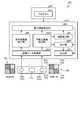
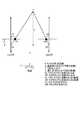
- FIG. 1is a schematic view of the information processing device IP1 of the first embodiment.
- the information processing device IP1is, for example, a stereo camera.
- the information processing device IP1includes, for example, a processing device PU1, a plurality of camera CAs, a projector PJ, and a storage device ST1.
- the processing device PU1is a device that extracts depth information and performs image processing using a plurality of image data acquired from a plurality of camera CAs.
- Image processingincludes, for example, foreground and background separation, refocusing and rewriting.
- Foreground-background separationis a process of separating the foreground and the background.
- Refocusingis a process of adjusting the focus of only a designated part so that the subject in the foreground stands out with respect to the background.
- Rewritingis a process of adjusting the brightness of a designated portion so that the subject in the foreground stands out against the background.
- Image processingis performed based on depth information.
- FIG. 2is a schematic view of the camera CA.
- the camera CAhas a lens LE, a UV cut filter UVF, a low-pass filter LPF, and an image sensor IS.
- the UV cut filter UVFcuts ultraviolet rays.
- the low-pass filter LPFpasses only light having a wavelength required for image information and cuts other light.
- the low-pass filter LPFintentionally blurs the image captured by the lens LE to suppress the occurrence of moire and false colors.
- the image sensor ISconverts the light coming from the lens LE into an electric signal.
- the image sensor IShas, for example, a lens array LA, a color filter array CFA, and a sensor plate SP.
- the sensor plate SPhas a plurality of light source conversion elements (photodiodes) PDs arranged two-dimensionally.
- the light source conversion element PDphotoelectrically converts the amount of electric charge according to the amount of incident light, stores it inside, and outputs it as a signal.
- the color filter array CFAhas a plurality of color filter CFs provided in a one-to-one correspondence with a plurality of light receiving elements PD.
- the lens array LAhas a plurality of microlens MLs that collect the light incident from the lens LE onto the plurality of light receiving elements PD.
- CMOSComplementary Metal Oxide Sensor
- CCDCharge-Coupled Device
- the color filter array CFAfor example, a primary color system color filter array and a complementary color system color filter array are used.
- the primary color filter arrayhas three color filter CFs of red, green and blue.
- the complementary color filter arrayhas four color filter CFs of cyan, yellow, magenta and green.
- a CMOS image sensor using a primary color filter arrayis used.
- the camera CAis used in a wide range of applications such as in-vehicle use.
- FIG. 3is a diagram showing an example of the configuration of the image sensor IS.
- the image sensor ISincludes a pixel array unit PA, a vertical drive unit VD, a column readout circuit unit CRC, a column signal processing unit CSP, a horizontal drive unit HD, a system control unit SC, and a signal processing unit SP.
- the pixel array unit PA, the vertical drive unit VD, the column readout circuit unit CRC, the column signal processing unit CSP, the horizontal drive unit HD, the system control unit SC, and the signal processing unit SPare, for example, ICs (Integrated) formed on the sensor plate SP. It is realized by a processing circuit PR such as Signal).
- the pixel array unit PAhas a plurality of pixels PX arranged two-dimensionally.
- the pixel PXincludes a photoelectric conversion element PD and a color filter CF.
- the pixel array unit PAincludes a plurality of pixel drive lines LD extending in the horizontal direction (row direction: left-right direction shown in the drawing) and a plurality of vertical pixel wiring LVs extending in the vertical direction (column direction: up-down direction shown in the drawing) in a grid pattern. It is provided in.
- the pixel drive line LDis provided for each pixel line extending in the horizontal direction.
- the vertical pixel wiring LVis provided for each pixel row extending in the vertical direction.
- One end of the pixel drive line LDis connected to the output end corresponding to each line of the vertical drive unit VD.
- the column readout circuit unit CRCincludes at least a circuit that supplies a constant current to the pixel PX in the selected row in the pixel array unit PA for each column, a current mirror circuit, a changeover switch for the pixel PX to be read out, and the like.
- the column readout circuit unit CRCconstitutes an amplifier together with the transistors in the selected pixels in the pixel array unit PA, converts the optical charge signal into a voltage signal, and outputs the light charge signal to the vertical pixel wiring LV.
- the vertical drive unit VDincludes a shift register, an address decoder, and the like.
- the vertical drive unit VDdrives each pixel PX of the pixel array unit PA in rows.
- the vertical drive unit VDhas a read scanning system and a sweep scanning system or a batch sweep and batch transfer system.
- the read-out scanning systemselectively scans the pixel PX of the pixel array unit PA row by row in order to read the pixel signal from the pixel PX.
- sweep scanningis performed ahead of the read scan performed by the read scan system by the time of the shutter speed.
- global exposureglobal shutter operation
- batch sweepingis performed in advance of the batch transfer by the time of the shutter speed.
- the electronic shutter operationrefers to an operation of discarding unnecessary light charges accumulated in the photodiode PD until just before and starting a new exposure (starting accumulation of light charges).
- the signal read by the read operation by the read scanning systemcorresponds to the amount of light incidented after the read operation or the electronic shutter operation immediately before that.
- the period from the read timing by the immediately preceding read operation or the sweep timing by the electronic shutter operation to the read timing by the current read operationis the light charge accumulation time (exposure time) in the pixel PX.
- the time from batch sweeping to batch transferis the accumulated time (exposure time).
- the pixel signal output from each pixel PX of the pixel row selectively scanned by the vertical drive unit VDis supplied to the column signal processing unit CSP through each of the vertical pixel wiring LVs.
- the column signal processing unit CSPperforms predetermined signal processing on the pixel signal output from each pixel PX of the selected row through the vertical pixel wiring LV for each pixel column of the pixel array unit PA, and the pixel after the signal processing. Hold the signal temporarily.
- the column signal processing unit CSPperforms at least noise removal processing, for example, CDS (Correlated Double Sampling: Correlation Double Sampling) processing as signal processing.
- CDSCorrelated Double Sampling: Correlation Double Sampling
- the CDS by the column signal processing unit CSPremoves pixel-specific fixed pattern noise such as reset noise and threshold variation of the amplification transistor AMP.
- the column signal processing unit CSPmay be provided with, for example, an AD conversion function so as to output the pixel signal as a digital signal.
- the horizontal drive unit HDincludes a shift register, an address decoder, and the like.
- the horizontal drive unit HDsequentially selects unit circuits corresponding to the pixel strings of the column signal processing unit CSP. By the selective scanning by the horizontal drive unit HD, the pixel signals signal-processed by the column signal processing unit CSP are sequentially output to the signal processing unit SP.
- the system control unit SCincludes a timing generator and the like that generate various timing signals.
- the system control unit SCperforms drive control of the vertical drive unit VD, the column signal processing unit CSP, the horizontal drive unit HD, and the like based on various timing signals generated by the timing generator.
- the image sensor ISfurther includes a signal processing unit SP and a data storage unit (not shown).
- the signal processing unit SPhas at least an addition processing function, and performs various signal processing such as addition processing on the pixel signal output from the column signal processing unit CSP.
- the data storage unittemporarily stores the data required for the signal processing in the signal processing unit SP.
- the processing of the signal processing unit SP and the data storage unitmay be replaced by an external signal processing unit provided on a substrate different from the image sensor IS, for example, a DSP (Digital Signal Processor) or software.
- DSPDigital Signal Processor
- a plurality of camera CAsare installed at different positions from each other. Therefore, the positions of the viewpoints of the plurality of cameras CA when shooting the subject are different from each other.
- the plurality of cameras CAoutput image data captured from a plurality of viewpoints to the processing device PU1.
- a first camera CA1 and a second camera CA2are provided as a plurality of camera CAs.
- the first camera CA1 and the second camera CA2are installed at symmetrical positions with respect to the projector PJ.
- the camera CAhas an image sensor IS capable of detecting both visible light and infrared light.
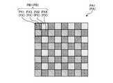
- the image sensor IShas, for example, a structure in which a plurality of pixel PXs for detecting visible light image information and a plurality of pixel PXs for detecting infrared image information are periodically arranged in a two-dimensional direction. ..
- the image sensor IShas a plurality of pixel blocks PB arranged two-dimensionally.
- the pixel block PBis, for example, one pixel PX1 for detecting red light, one pixel PX2 for detecting green light, one pixel PX3 for detecting blue light, and one pixel for detecting infrared rays. It has a structure in which PX4 and PX4 are arranged in 2 rows and 2 columns.
- the pixel PX1includes, for example, a color filter CF that selectively transmits red light and selectively absorbs green light, blue light, and infrared light.
- the pixel PX2includes, for example, a color filter CF that selectively transmits green light and selectively absorbs red light, blue light, and infrared light.
- the pixel PX3includes, for example, a color filter CF that selectively transmits blue light and selectively absorbs red light, green light, and infrared light.
- the pixel PX4is not provided with, for example, a color filter CF that absorbs infrared rays.
- the color filter array CFA of the portion corresponding to the pixel PX4is a transparent layer and transmits red light, green light, blue light, and infrared light.
- the projector PJprojects an infrared projection pattern on the subject.
- the infrared projection patterna known pattern used in a spot light projection method, a slit light projection method, a pattern light projection method, or the like is adopted.
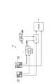
- the processing device PU1includes, for example, an image data acquisition unit IDO, an infrared image extraction unit IRE, a visible light image extraction unit VLE1, a depth information extraction unit DIE1, a distance detection unit DD, a processing unit IMP, and an output unit OT. And have.
- the image data acquisition unit IDOacquires, for example, a plurality of image data taken from a plurality of viewpoints from a plurality of camera CAs. Each of the plurality of image data includes visible light image information and infrared image information.
- the image data acquisition unit IDOoutputs a plurality of image data to the infrared image extraction unit IRE and the visible light image extraction unit VLE1.
- the infrared image extraction unit IREextracts an infrared image from a plurality of image data using the infrared image information for each image data, for example.
- the infrared image extraction unit IREoutputs a plurality of infrared images extracted from the plurality of image data to the depth information extraction unit DIE1.
- the visible light image extraction unit VLE1extracts a visible light image from a plurality of image data using the visible light image information for each image data, for example.
- the visible light image extraction unit VLE1outputs a plurality of visible light images extracted from a plurality of image data to the depth information extraction unit DIE1 and the distance detection unit DD.
- the visible light image extraction unit VLE1outputs at least one visible light image out of a plurality of visible light images extracted from the plurality of image data to the processing unit IMP.
- the infrared image and the visible light imageare extracted using the red, green, blue and infrared light intensity values (hereinafter referred to as color values) of each pixel PX calculated by the demosaic process.
- the signal processing unit SPperforms demosy processing on the detected value of each pixel PX.
- the demosaic processis a process of complementing information on the wavelength of light (hereinafter referred to as a color) that is lost for each pixel PX based on the detected values of the surrounding pixels PX.
- the infrared image extraction unit IREextracts an infrared image using, for example, the infrared color value of each pixel PX.
- the visible light image extraction unit VLE1extracts a visible light image using, for example, the red, green, and blue color values of each pixel PX.
- the demosaic processcan be performed by various known methods.
- As a simple methodthere is a method of linearly interpolating with the detection values of a plurality of pixels PX in charge of the same color in the vicinity.
- the color information of each pixel PXmay be estimated using a machine learning technique.
- the signal processing unit SPestimates the color value of each color for each pixel PX from the detected value of each pixel PX by using an analysis model in which the relationship between the known brightness distribution and the detected value of each pixel PX is machine-learned. can do.
- Depth information extraction unit DIE1extracts depth information from a plurality of image data taken from a plurality of viewpoints by a plurality of camera CAs.
- the depth information extraction unit DIE1outputs the depth information as a depth map to the processing unit IMP and the output unit OT.
- the depth mapis data defined by associating the depths of a plurality of measurement points set in the captured image of the camera CA with the coordinates of the respective measurement points.
- the depth information extraction unit DIE1has, for example, a passive stereo mode and an active stereo mode.
- the passive stereo modeis a stereo mode that extracts depth information from a plurality of visible light image information included in a plurality of image data.
- the active stereo modeis a stereo mode that extracts depth information from a plurality of infrared image information included in a plurality of image data.
- the depth information extraction unit DIE1switches between the passive stereo mode and the active stereo mode according to the situation.
- the depth information extraction unit DIE1switches between the passive stereo mode and the active stereo mode according to the situation based on the distance from the subject. For example, when the distance from the subject is larger than the threshold value, the depth information extraction unit DIE1 extracts the depth information in the passive stereo mode. When the distance from the subject is equal to or less than the threshold value, the depth information extraction unit DIE1 extracts the depth information in the active stereo mode.
- the interval of the infrared projection pattern reflected in the image of the camera CAchanges according to the distance from the subject.
- aliasingmay occur in relation to the arrangement density of the pixel PX4 that detects the infrared image information.
- the depth informationcan be detected with high accuracy.
- the depth information extraction unit DIE1switches the stereo mode based on, for example, the distance between the camera CA and the subject detected by the distance detection unit DD.
- the distance between the camera CA and the subjectis calculated as, for example, the average value of the depth information (distance) of all the measurement points in the captured image of the camera CA, or the distance between the main subject and the camera CA.
- the distance detection unit DDextracts depth information of some or all measurement points in the captured image by a passive stereo method using, for example, a plurality of visible light images extracted by the visible light image extraction unit VLE1.
- the distance detection unit DDdetects the distance between the camera CA and the subject based on the extracted depth information.
- the processing unit IMPprocesses the visible light image generated by using the visible light image information included in at least one of the plurality of image data based on the depth information. For example, one of the plurality of camera CAs is selected as the reference camera. How you choose the reference camera is optional. In this embodiment, for example, the first camera CA1 is selected as the reference camera.
- the processing unit IMPprocesses the visible light image (reference image) generated by using the visible light image information included in the image data of the reference camera based on the depth information (foreground background separation, refocusing, rewriting, etc.). To give.
- the processing unit IMPoutputs a visible light image (processed image) obtained by image processing to the output unit OT.
- the output unit OToutputs the visible light image output from the processing unit INP and the depth information output from the depth information extraction unit DIE1 to an external device.
- the storage device ST1stores, for example, the program PG1 executed by the processing device PU1.
- the program PG1is a program that causes a computer to execute information processing according to the present embodiment.
- the processing device PU1performs various processes according to the program PG1 stored in the storage device ST1.
- the storage device ST1may be used as a work area for temporarily storing the processing result of the processing device PU1.
- the storage device ST1includes any non-transient storage medium such as, for example, a semiconductor storage medium and a magnetic storage medium.
- the storage device ST1includes, for example, an optical disk, a magneto-optical disk, or a flash memory.
- the program PG1is stored, for example, in a non-transient storage medium that can be read by a computer.
- the processing device PU1is, for example, a computer composed of a processor and a memory.
- the memory of the processing device PU1includes a RAM (Random Access Memory) and a ROM (Read Only Memory).
- the processing device PU1executes the image data acquisition unit IDO, the infrared image extraction unit IRE, the visible light image extraction unit VLE1, the depth information extraction unit DIE1, the distance detection unit DD, the processing unit IMP, and the output unit OT. Functions as.
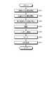
- FIGS. 4 and 5are diagrams showing an example of the information processing method of the present embodiment.
- FIG. 4is a conceptual diagram of information processing.
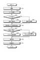
- FIG. 5is a flowchart showing an information processing method.
- step S1the plurality of camera CAs capture the subject from a plurality of viewpoints.
- the first camera CAcaptures image data of the first viewpoint.
- the second camera CA2captures image data of the second viewpoint.
- the image data acquisition unit IDOacquires a plurality of image data taken from a plurality of viewpoints.
- the visible light image extraction unit VLE1extracts a visible light image from a plurality of image data using the visible light image information for each image data.
- step S2the distance detection unit DD uses a plurality of visible light images extracted from a plurality of image data to obtain depth information of some or all measurement points in the captured image of the camera CA by a passive stereo method. Extract. The distance detection unit DD detects the distance between the camera CA and the subject by using the extracted depth information.
- step S3the depth information extraction unit DIE1 determines whether or not the distance detected by the distance detection unit DD is larger than the threshold value. If it is determined in step S3 that the distance is larger than the threshold value (step S3: Yes), the process proceeds to step S4.
- step S4the depth information extraction unit DIE1 selects the passive stereo mode. The depth information extraction unit DIE1 extracts depth information by a passive stereo method using a plurality of visible light images extracted by the visible light image extraction unit VLE1. Then, the process proceeds to step S6.
- the depth information extraction unit DIE1has the depth information extracted by the distance detection unit DD. Is output to the processing unit IMP and the output unit OT as it is.
- step S3If it is determined in step S3 that the distance is equal to or less than the threshold value (step S3: No), the process proceeds to step S5.
- step S5the depth information extraction unit DIE1 selects the active stereo mode.
- the depth information extraction unit DIE1extracts depth information by an active stereo method using a plurality of infrared images extracted by the infrared image extraction unit IRE. Then, the process proceeds to step S6.
- the processing unit IMPpreprocesses the visible light image acquired from the visible light image extraction unit VLE1.
- This visible light imageis a reference image generated by using the visible light image information included in the image data of the first camera CA1 (reference camera).
- the preprocessingincludes, for example, missing part interpolation processing and upsampling processing.
- the missing part interpolation processis a process of obtaining the missing information by interpolation.
- the upsampling processis a process of converting the sampling frequency to a higher value.
- step S7the processing unit IMP performs image processing (foreground background separation, refocusing, rewriting, etc.) based on the depth information on the preprocessed visible light image.
- image processingforeground background separation, refocusing, rewriting, etc.
- the information processing device IP1has a depth information extraction unit DIE1 and a processing unit IMP.
- the depth information extraction unit DIE1can extract depth information from a plurality of infrared image information included in a plurality of image data.
- the plurality of image dataare image data taken from a plurality of viewpoints.
- Each of the plurality of image dataincludes visible light image information and infrared image information.
- the processing unit IMPprocesses a visible light image generated by using the visible light image information included in at least one of the plurality of image data based on the depth information.
- the information processing of the above-mentioned information processing deviceis executed by the computer.
- the program of the present embodimentmakes the computer realize the information processing of the above-mentioned information processing apparatus.
- infrared image information for detecting depth information and visible light image information for generating a viewing imageare included in the image data of the same viewpoint. Therefore, the position shift between the depth map generated by using the depth information and the visible light image is unlikely to occur. Therefore, image processing using the depth information can be easily performed.
- the Depth information extraction unit DIE1switches between passive stereo mode and active stereo mode according to the situation.
- the passive stereo modeis a stereo mode that extracts depth information from a plurality of visible light image information included in a plurality of image data.
- the active stereo modeis a stereo mode that extracts depth information from a plurality of infrared image information included in a plurality of image data.
- Passive stereo mode and active stereo modehave their advantages and disadvantages, respectively. By switching the stereo mode according to the situation, each other's weaknesses can be compensated.
- Depth information extraction unit DIE1switches between passive stereo mode and active stereo mode according to the situation based on the distance from the subject.
- the interval of the infrared projection pattern reflected in the image of the camera CAchanges according to the distance from the subject.
- aliasingmay occur in relation to the arrangement density of the pixel PX4 that detects the infrared image information.
- the depth informationcan be detected with high accuracy.
- the information processing device IP1has a plurality of image sensors IS that capture a plurality of image data.
- Each of the plurality of image sensor ISshas a plurality of pixel PXs (pixels PX1, PX2, PX3) for detecting visible light image information, and a plurality of pixel PXs (pixels PX4) for detecting infrared image information. It has a structure that is periodically arranged in the two-dimensional direction.
- infrared image information and visible light image informationare easily separated and extracted.
- Each of the plurality of image sensors IShas a plurality of pixel blocks PB arranged two-dimensionally.
- Each of the plurality of pixel blocks PBhas one pixel PX1 for detecting red light, one pixel PX2 for detecting green light, one pixel PX3 for detecting blue light, and one pixel PX3 for detecting infrared light. It has a structure in which pixels PX4 and pixels are arranged in 2 rows and 2 columns.
- red, green, blue and infrared informationis detected in a well-balanced manner.
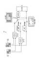
- FIG. 6is a schematic view of the information processing apparatus IP2 of the second embodiment.
- the difference between the first embodiment and the first embodimentis that the depth information is extracted by the active stereo method and the processing device PU2 has the pattern control unit PTC.
- the differences from the first embodimentwill be mainly described.
- the visible light image extraction unit VLE2does not output the plurality of visible light images extracted from the plurality of image data to the depth information extraction unit DIE2.
- the distance detection unit DDoutputs information on the distance between the camera CA and the subject (distance from the subject) to the pattern control unit PTC.
- the pattern control unit PTCchanges the infrared projection pattern IRP used in the active stereo mode according to the distance from the subject.
- the pattern control unit PTCprojects a coarse long-distance pattern with a large distance between spots or slits as an infrared projection pattern IRP.
- the pattern control unit PTCprojects a fine short-distance pattern with a narrow distance between spots or slits as an infrared projection pattern IRP.
- the storage device ST2stores, for example, the program PG2 executed by the processing device PU2.
- the program PG2is a program that causes a computer to execute information processing according to the present embodiment.
- the processing device PU2performs various processes according to the program PG2 stored in the storage device ST2.
- the processing device PU2executes the image data acquisition unit IDO, the infrared image extraction unit IRE, the visible light image extraction unit VLE2, the depth information extraction unit DIE2, the distance detection unit DD, the processing unit IMP, and the output unit OT. And functions as a pattern control unit PTC.
- FIGS. 7 and 8are diagrams showing an example of the information processing method of the present embodiment.
- FIG. 7is a conceptual diagram of information processing.
- FIG. 8is a flowchart showing an information processing method.
- step S11the plurality of camera CAs capture the subject from a plurality of viewpoints.
- the image data acquisition unit IDOacquires a plurality of image data taken from a plurality of viewpoints.
- the visible light image extraction unit VLE1extracts a visible light image from a plurality of image data using the visible light image information for each image data.
- step S12the distance detection unit DD uses a plurality of visible light images extracted from the plurality of image data to extract depth information of a part or all of the measurement points in the photographing area by the passive stereo method.
- the distance detection unit DDdetects the distance between the camera CA and the subject by using the extracted depth information.
- step S13the pattern control unit PTC determines whether or not the distance detected by the distance detection unit DD is larger than the threshold value. If it is determined in step S13 that the distance is larger than the threshold value (step S13: Yes), the process proceeds to step S14.
- step S14the pattern control unit PTC projects a long-distance pattern as an infrared projection pattern IRP.
- the depth information extraction unit DIE2extracts depth information by an active stereo method using a plurality of infrared images in which a long-distance pattern is reflected. Then, the process proceeds to step S16.
- step S13If it is determined in step S13 that the distance is equal to or less than the threshold value (step S13: No), the process proceeds to step S15.
- step S15the pattern control unit PTC projects a short-range pattern as an infrared projection pattern IRP.
- the depth information extraction unit DIE2extracts depth information by an active stereo method using a plurality of infrared images in which a pattern for a short distance is reflected. Then, the process proceeds to step S16.
- step S16the processing unit IMP preprocesses the visible light image acquired from the visible light image extraction unit VLE2.
- This visible light imageis a reference image generated by using the visible light image information included in the image data of the first camera CA1 (reference camera).
- step S17the processing unit IMP performs image processing based on the depth information on the preprocessed visible light image.
- the information processing device IP2has a pattern control unit PTC.
- the pattern control unit PTCchanges the infrared projection pattern used in the active stereo mode according to the distance from the subject. According to this configuration, the occurrence of aliasing is suppressed.
- FIG. 9is a schematic view of the information processing apparatus IP3 of the third embodiment.
- the difference between the first embodiment and the first embodimentis that the depth information extraction unit DIE3 switches between the passive stereo mode and the active stereo mode according to the situation based on the shooting scene.
- the differences from the first embodimentwill be mainly described.
- the processing device PU3has, for example, a scene detection unit SD.
- the visible light image extraction unit VLE3outputs, for example, one of a plurality of visible light images extracted from a plurality of image data to the scene detection unit SD.
- the scene detection unit SDdetects a shooting scene based on, for example, a visible light image output from the visible light image extraction unit VLE3.
- the shooting scenes to be detectedinclude, for example, "daytime & outdoor", “indoor” and “dark”. "Daytime & Outdoor” indicates a shooting scene outdoors during the daytime. "Indoor” indicates an indoor shooting scene. "Dark” indicates a shooting scene in a dark environment.
- a shooting sceneis detected based on a visible light image (reference image) extracted from image data captured by the reference camera (first camera CA1).
- a known scene recognition technology using AI (artificial intelligence) used in digital cameras, smartphones, etc.is used to detect the shooting scene.
- AIartificial intelligence
- Japanese Patent Application Laid-Open No. 2013-526215it is also possible to determine whether the environment is an indoor environment or an outdoor environment from the strength of GPS signals.
- the information processing device IP3has an illuminance sensor
- the information of the illuminance sensormay be combined with the method described above to determine the shooting scene.
- the depth information extraction unit DIE3switches the stereo mode based on, for example, the shooting scene detected by the scene detection unit SD. For example, when “daytime & outdoor” is detected as a shooting scene, the depth information extraction unit DIE3 extracts the depth information in the passive stereo mode. When “indoor” or “dark” is detected as the shooting scene, the depth information extraction unit DIE3 extracts the depth information in the active stereo mode.
- the storage device ST3stores, for example, the program PG3 executed by the processing device PU3.
- the program PG3is a program that causes a computer to execute information processing according to the present embodiment.
- the processing device PU3performs various processes according to the program PG3 stored in the storage device ST3.
- the processing device PU3executes the image data acquisition unit IDO, the infrared image extraction unit IRE, the visible light image extraction unit VLE3, the depth information extraction unit DIE3, the scene detection unit SD, the processing unit IMP, and the output unit OT. Functions as.
- FIG. 10 and 11are diagrams showing an example of the information processing method of the present embodiment.
- FIG. 10is a conceptual diagram of information processing.
- FIG. 11is a flowchart showing an information processing method.
- step S21the plurality of camera CAs photograph the subject from a plurality of viewpoints.
- the image data acquisition unit IDOacquires a plurality of image data taken from a plurality of viewpoints.
- the visible light image extraction unit VLE3extracts a visible light image from a plurality of image data using the visible light image information for each image data.
- step S22the scene detection unit SD detects the shooting scene based on one of the plurality of visible light images extracted by the visible light image extraction unit VLE3.
- step S23the depth information extraction unit DIE3 determines whether or not "daytime & outdoor" is detected as the shooting scene. If it is determined in step S23 that "daytime & outdoor" is detected (step S23: Yes), the process proceeds to step S24.
- step S24the depth information extraction unit DIE3 selects the passive stereo mode. The depth information extraction unit DIE3 extracts depth information by a passive stereo method using a plurality of visible light images extracted by the visible light image extraction unit VLE3. Then, the process proceeds to step S26.
- step S23If it is determined in step S23 that "daytime & outdoor" is not detected (step S23: No), the process proceeds to step S25.
- step S25the depth information extraction unit DIE3 selects the active stereo mode.
- the depth information extraction unit DIE3extracts depth information by an active stereo method using a plurality of infrared images extracted by the infrared image extraction unit IRE. Then, the process proceeds to step S26.
- step S26the processing unit IMP preprocesses the visible light image acquired from the visible light image extraction unit VLE3.
- This visible light imageis a reference image generated by using the visible light image information included in the image data of the first camera CA1 (reference camera).
- step S27the processing unit IMP performs image processing based on the depth information on the preprocessed visible light image.
- the depth information extraction unit DIE3switches between the passive stereo mode and the active stereo mode according to the situation based on the shooting scene, for example.
- the detection accuracy of depth informationchanges depending on the shooting scene.
- an infrared component derived from ambient lightis detected as noise. Therefore, it is difficult to accurately detect the depth information when shooting in strong sunlight.
- the passive stereo methodthe subject cannot be sufficiently detected in a dark environment. Depth information can be detected accurately by switching the stereo mode according to the shooting scene.
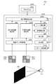
- FIG. 12is a schematic view of the information processing apparatus IP4 of the fourth embodiment.
- the difference between the first embodiment and the third embodiment in this embodimentis that the depth information extraction unit DIE4 switches between the passive stereo mode and the active stereo mode according to the situation based on both the distance from the subject and the shooting scene. It is a point.
- the differences between the first embodiment and the third embodimentwill be mainly described.
- the processing device PU4has, for example, both a distance detection unit DD and a scene detection unit SD.
- the depth information extraction unit DIE4switches the stereo mode based on, for example, both the distance from the subject detected by the distance detection unit DD and the shooting scene detected by the scene detection unit SD. For example, when “daytime & outdoor” is detected as a shooting scene, the depth information extraction unit DIE4 selects the outdoor control mode. When “indoor” or “dark” is detected as the shooting scene, the depth information extraction unit DIE4 selects the indoor control mode.
- the outdoor control modeis a control in which the passive stereo mode is positively selected.
- the indoor control modeis a control in which the active stereo mode is positively selected.
- the distance condition (threshold value) for switching the stereo modediffers between the outdoor control mode and the indoor control mode.
- the depth information extraction unit DIE4extracts the depth information in the passive stereo mode.
- the depth information extraction unit DIE4extracts the depth information in the active stereo mode.
- the depth information extraction unit DIE4extracts the depth information in the passive stereo mode.
- the depth information extraction unit DIE4extracts the depth information in the active stereo mode.
- the first thresholdis smaller than the second threshold. Therefore, if the distance from the subject is the same, the range of the distance in which the passive stereo mode is selected is wider when the outdoor control mode is selected than when the indoor control mode is selected. Therefore, when the outdoor control mode is selected, the passive stereo mode is positively selected. On the contrary, if the distance from the subject is the same, the range of the distance in which the active stereo mode is selected is wider when the indoor control mode is selected than when the outdoor control mode is selected. Therefore, when the indoor control mode is selected, the active stereo mode is positively selected.
- infrared components derived from ambient lightare detected as noise. Outdoors during the daytime, the detected values derived from the infrared projection pattern are easily buried in ambient noise due to the influence of infrared rays contained in the ambient light (sunlight). Therefore, it is difficult to accurately detect the depth information when shooting in strong sunlight. Such a decrease in detection accuracy becomes more remarkable as the distance from the subject increases. Therefore, by positively selecting the passive stereo mode in such a case, the depth information can be detected with high accuracy.
- the depth informationcan be detected with high accuracy.
- the storage device ST4stores, for example, the program PG4 executed by the processing device PU4.
- the program PG4is a program that causes a computer to execute information processing according to the present embodiment.
- the processing device PU4performs various processes according to the program PG4 stored in the storage device ST4.
- the processing device PU4executes an image data acquisition unit IDO, an infrared image extraction unit IRE, a visible light image extraction unit VLE4, a depth information extraction unit DIE4, a distance detection unit DD, a scene detection unit SD, and a processing unit. Functions as an IMP and an output unit OT.
- FIG. 13 and 14are diagrams showing an example of the information processing method of the present embodiment.
- FIG. 13is a conceptual diagram of information processing.
- FIG. 14is a flowchart showing an information processing method.
- step S31the plurality of camera CAs photograph the subject from a plurality of viewpoints.
- the image data acquisition unit IDOacquires a plurality of image data taken from a plurality of viewpoints.
- the visible light image extraction unit VLE4extracts a visible light image from a plurality of image data using the visible light image information for each image data.
- step S32the scene detection unit SD detects the shooting scene based on one of the plurality of visible light images extracted by the visible light image extraction unit VLE4.
- step S33the depth information extraction unit DIE4 determines whether or not "daytime & outdoor" is detected as the shooting scene. If it is determined in step S33 that "daytime & outdoor" is detected (step S33: Yes), the process proceeds to step S34. In step S34, the depth information extraction unit DIE3 selects the outdoor control mode. Then, the process proceeds to step S36.
- step S33If it is determined in step S33 that "daytime & outdoor" is not detected (step S33: No), the process proceeds to step S35.
- step S35the depth information extraction unit DIE4 selects the indoor control mode. Then, the process proceeds to step S36.
- step S36the distance detection unit DD uses a plurality of visible light images extracted from the plurality of image data to obtain depth information of some or all measurement points in the captured image of the camera CA by the passive stereo method. Extract. The distance detection unit DD detects the distance between the camera CA and the subject by using the extracted depth information.
- step S37the depth information extraction unit DIE4 determines whether or not the distance detected by the distance detection unit DD is larger than the threshold value.
- the threshold value that serves as a reference for determination in step S37differs depending on whether the outdoor control mode is selected or the indoor control mode is selected.
- the threshold when the outdoor control mode is selectedis the first threshold.
- the threshold when the indoor control mode is selectedis the second threshold.
- the first thresholdis smaller than the second threshold.
- step S37determines whether the distance is larger than the threshold value (step S37: Yes). If it is determined in step S37 that the distance is larger than the threshold value (step S37: Yes), the process proceeds to step S38.
- step S38the depth information extraction unit DIE4 selects the passive stereo mode.
- the depth information extraction unit DIE4extracts depth information by a passive stereo method using a plurality of visible light images extracted by the visible light image extraction unit VLE4. Then, the process proceeds to step S40.
- the distance detection unit DDhas extracted the depth information of all the measurement points in the captured image of the camera CA in step S36
- the depth information extraction unit DIE4has the depth information extracted by the distance detection unit DD. Is output to the processing unit IMP and the output unit OT as it is.
- step S37determines whether the distance is equal to or less than the threshold value (step S37: No). If it is determined in step S37 that the distance is equal to or less than the threshold value (step S37: No), the process proceeds to step S39.
- step S39the depth information extraction unit DIE4 selects the active stereo mode. The depth information extraction unit DIE4 extracts depth information by an active stereo method using a plurality of infrared images extracted by the infrared image extraction unit IRE. Then, the process proceeds to step S40.
- step S40the processing unit IMP preprocesses the visible light image acquired from the visible light image extraction unit VLE4.
- This visible light imageis a reference image generated by using the visible light image information included in the image data of the first camera CA1 (reference camera).
- step S41the processing unit IMP performs image processing based on the depth information on the preprocessed visible light image.
- the depth information extraction unit DIE4switches between the passive stereo mode and the active stereo mode according to the situation based on both the distance from the subject and the shooting scene. Therefore, the depth information is accurately detected in various situations.
- FIG. 15is a schematic view of the information processing device IP5 of the fifth embodiment.
- the difference from the fourth embodiment in this embodimentis that the distance information from the subject detected by the distance detection unit DD is used for controlling the infrared projection pattern by the pattern control unit PTC shown in the second embodiment. It is a point.
- the differences from the second embodiment and the fourth embodimentwill be mainly described.
- the processing device PU2has a pattern control unit PTC.
- the function of the pattern control unit PTCis the same as that described in the second embodiment.
- the pattern control unit PTCchanges the infrared projection pattern IRP used in the active stereo mode according to the distance from the subject.
- the distance detection unit DDdetects the distance from the subject based on a plurality of visible light images extracted by the visible light image extraction unit VLE5.
- the pattern control unit PTCprojects the long-distance pattern as an infrared projection pattern IRP.
- the depth information extraction unit DIE5extracts depth information by an active stereo method using a plurality of infrared images in which a long-distance pattern is reflected.
- the pattern control unit PTCprojects the short-distance pattern as an infrared projection pattern IRP.
- the depth information extraction unit DIE5extracts depth information by an active stereo method using a plurality of infrared images in which a pattern for a short distance is reflected.
- the distance condition (threshold value) for switching the infrared projection pattern IRPdiffers between the outdoor control mode and the indoor control mode.
- the pattern control unit PTCprojects a long-distance pattern as an infrared projection pattern IRP.
- the pattern control unit PTCprojects a short-distance pattern as an infrared projection pattern IRP.
- the pattern control unit PTCprojects a long-distance pattern as an infrared projection pattern IRP.
- the pattern control unit PTCprojects a short-distance pattern as an infrared projection pattern IRP.
- the storage device ST5stores, for example, the program PG5 executed by the processing device PU5.
- the program PG5is a program that causes a computer to execute information processing according to the present embodiment.
- the processing device PU5performs various processes according to the program PG5 stored in the storage device ST5.
- the processing device PU5executes an image data acquisition unit IDO, an infrared image extraction unit IRE, a visible light image extraction unit VLE5, a depth information extraction unit DIE5, a distance detection unit DD, a scene detection unit SD, and a processing unit. It functions as an IMP, an output unit OT, and a pattern control unit PTC.
- the effect of suppressing the occurrence of aliasing when the distance from the subject is increasedcan be obtained.
- [6. Variation of pixel array part] 16 to 21are diagrams showing variations of the pixel array unit PA.
- FIG. 16is a diagram showing a pixel array unit PA1 according to the first variation.
- the pixel array unit PA1is the same as that shown in the first to fifth embodiments.
- the image sensor IShas a plurality of pixel blocks PB1 arranged two-dimensionally.
- Each of the plurality of pixel blocks PB1has one pixel PX1 for detecting red light, one pixel PX2 for detecting green light, one pixel PX3 for detecting blue light, and one pixel PX3 for detecting infrared light. It has a structure in which pixels PX4 and pixels are arranged in 2 rows and 2 columns.
- red, green, blue and infrared informationis detected in a well-balanced manner.
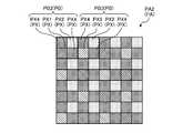
- FIG. 17is a diagram showing a pixel array unit PA2 according to the second variation.
- the image sensor IShas a structure in which a plurality of pixel blocks (first pixel block) PB2 and a plurality of pixel blocks (second pixel block) PB3 are periodically arranged in a two-dimensional direction.
- first pixel blockfirst pixel block
- second pixel blocksecond pixel block
- Each of the plurality of pixel blocks PB3has, for example, one pixel PX2 for detecting green light, one pixel PX3 for detecting blue light, and two pixels PX4 for detecting infrared rays in 2 rows and 2 columns. It has an arranged structure.
- the pixels PX4 for detecting infrared raysare arranged at high density. Therefore, the resolution of infrared rays is increased. Since the sensitivity of infrared rays is also increased, the distance (threshold value) to the subject from which depth information can be extracted in the active stereo mode is increased. Further, the pixel PX1 for detecting red light, the pixel PX2 for detecting green light, and the pixel PX3 for detecting blue light are uniformly arranged in the same cycle. Therefore, red, blue, and green information is detected in a well-balanced manner.
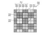
- FIG. 18is a diagram showing a pixel array unit PA3 according to the third variation.
- the image sensor IShas a plurality of pixel units PU1 arranged two-dimensionally.
- Each of the plurality of pixel units PU1has a plurality of pixel blocks PB to which different colors are assigned.
- Each of the plurality of pixel blocks PBincludes a plurality of pixel PXs arranged adjacent to each other.
- the plurality of pixel PXs constituting the pixel block PBdetect the light of the color assigned to the pixel block PB.
- the pixel unit PU1has a structure in which the pixel block PB1, the pixel block PB2, the pixel block PB3, and the pixel block PB4 are arranged in 2 rows and 2 columns.
- the pixel block PB1is a pixel block PB to which red is assigned.
- four pixels PX1 for detecting red lightare arranged in 2 rows and 2 columns.
- the pixel block PB2is a pixel block PB to which green is assigned.
- four pixels PX2 for detecting green lightare arranged in 2 rows and 2 columns.
- the pixel block PB3is a pixel block PB to which blue is assigned.
- the pixel block PB3In the pixel block PB3, four pixels PX3 for detecting blue light are arranged in 2 rows and 2 columns.
- the pixel block PB4is a pixel block PB to which infrared rays are assigned.
- four pixels PX4 for detecting infrared raysare arranged in 2 rows and 2 columns.
- the image sensor ISis assigned a plurality of pixel blocks PB1 to which red is assigned, a plurality of pixel blocks PB2 to which green is assigned, a plurality of pixel blocks PB3 to which blue is assigned, and infrared rays. It has a structure in which the plurality of pixel blocks PB4 and the plurality of pixel blocks PB4 are arranged periodically in the two-dimensional direction. Therefore, binning can be performed for each pixel block to detect red, green, blue, and infrared information with high sensitivity. Since the sensitivity of infrared rays is also increased, the distance (threshold value) to the subject from which depth information can be extracted in the active stereo mode is increased.
- the pixel PX1 for detecting red light, the pixel PX2 for detecting green light, and the pixel PX3 for detecting blue lightare uniformly arranged at the same cycle. Therefore, red, blue, and green information is detected in a well-balanced manner.
- FIG. 19is a diagram showing a pixel array unit PA4 according to the fourth variation.
- the image sensor IShas a plurality of pixel units PU2 arranged two-dimensionally.
- the pixel unit PU2has a structure in which one pixel block PB2, one pixel block PB4, and two pixel blocks PB5 are arranged in two rows and two columns.
- the pixel block PB5has a structure in which one pixel PX1, one pixel PX2, and two pixels PX3 are arranged in two rows and two columns.
- the pixel block PB2 and the pixel block PB4are arranged so as not to be adjacent to each other in both the row direction and the column direction.
- the number of pixels PX2 that detect green lightis the largest. Green is the color with the highest luminosity factor for the human eye. By increasing the number of pixels PX2, the apparent resolution is increased.
- FIG. 20is a diagram showing a pixel array unit PA5 according to the fifth variation.
- the image sensor IShas a plurality of pixel units PU3 arranged two-dimensionally.
- the pixel unit PU3has a structure in which one pixel block PB2, one pixel block PB4, and two pixel blocks PB5 are arranged in two rows and two columns.
- the pixel block PB2 and the pixel block PB4are arranged adjacent to each other in the column direction.
- FIG. 21is a diagram showing a pixel array unit PA6 according to the sixth variation.
- the image sensor IShas a plurality of pixel units PU4 arranged two-dimensionally.
- the pixel unit PU4has a structure in which one pixel block PB5, one pixel block PB6, one pixel block PB7, and one pixel block PB8 are arranged in two rows and two columns.
- the pixel block PB6has a structure in which one pixel PX2 and three pixels PX4 are arranged in 2 rows and 2 columns.
- the pixel block PB7has a structure in which two pixels PX2, one pixel PX3, and one pixel PX4 are arranged in two rows and two columns.
- the pixel block PB8has a structure in which one pixel PX1, two pixels PX2, and one pixel PX4 are arranged in two rows and two columns.
- the number of pixels PX2 that detect green light and pixel PX4 that detects infrared raysis the largest. Therefore, the sensitivity of infrared rays is high, and the apparent resolution for visible light images is also high.
- FIG. 22is a schematic view of the information processing apparatus IP6 of the sixth embodiment.
- the difference between the first embodiment and the first embodimentis that the infrared sensitivities of the plurality of camera CAs are different, the exposure times of the plurality of camera CAs are different depending on the infrared sensitivities, and the processing device PU6 exposes the light.
- the pointis that it has a compositing unit IMC that synthesizes a plurality of visible light images having different times.
- the differences from the first embodimentwill be mainly described.
- the plurality of image sensors IS included in the plurality of camera CAsall have the same structure.
- the infrared sensitivities of the plurality of image sensors ISare different from each other.
- an infrared cut filteris provided on the pixels PX (PX5, PX6) for detecting infrared image information of one or more cameras CA. This infrared cut filter absorbs a part of infrared rays incident on the pixel PX for detecting infrared image information.
- the processing device PU6has, for example, an exposure control unit ETC.
- the exposure control unit ETCfor example, makes the exposure time of the plurality of image sensors IS different according to the sensitivity of each infrared ray of the plurality of image sensors IS.
- the exposure control unit ETClengthens the exposure time as the image sensor IS has lower infrared sensitivity. As a result, the exposure control unit ETC aligns the brightness levels of the infrared images detected by the plurality of image sensors.
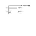
- FIG. 23is a diagram showing the relationship between the infrared transmission amount and the exposure time of the first camera CA3 and the second camera CA4.
- FIG. 24is a diagram showing the exposure amount of visible light of the first camera CA3 and the second camera CA4.
- the amount of infrared transmission detected by the light receiving element PD of the pixel PX6 of the second camera CA4is smaller than the amount of infrared transmission detected by the light receiving element PD of the pixel PX5 of the first camera CA3.
- the exposure control unit ETCsets the exposure time of the second camera CA4 to the second. It is 1 / Q times longer than the exposure time of 1 camera CA3. Therefore, the infrared detection value of the pixel PX6 is equal to the infrared detection value of the pixel PX5.
- the exposure amount of visible light of the pixels PX1, PX2, and PX3is larger in the second camera CA4 than in the first camera CA3.
- the image data acquisition unit IDOacquires a plurality of image data taken under different exposure conditions from the plurality of camera CAs.
- Each of the plurality of image dataincludes visible light image information and infrared image information.
- the image data acquisition unit IDOoutputs a plurality of image data to the infrared image extraction unit IRE and the visible light image extraction unit VLE6.
- the infrared image extraction unit IREextracts an infrared image from a plurality of image data using infrared image information for each image data.
- the plurality of image dataare photographed under exposure conditions such that the infrared detection value of the pixel PX5 is equal to the infrared detection value of the pixel PX6. Therefore, the brightness levels of the plurality of infrared images extracted from the plurality of image data are equal to each other.
- the infrared image extraction unit IREoutputs a plurality of infrared images extracted from the plurality of image data to the depth information extraction unit DIE6.
- the depth information extraction unit DIE6extracts depth information from a plurality of infrared images extracted by the infrared image extraction unit IRE by an active stereo method.
- the visible light image extraction unit VLE6extracts a visible light image from a plurality of image data having different visible light exposure times by using the visible light image information for each image data.
- the brightness levels of the plurality of extracted visible light imagesare different from each other, unlike the first embodiment.
- the visible light image extracted from the image data of the second camera CA4is an image having a high level of brightness (long storage image).
- the visible light image extracted from the image data of the first camera CA3is an image having a low brightness level (short storage image).
- the second camera CA4 that acquires a long-stored imagemay be referred to as a long-stored camera
- the first camera CA3 that acquires a short-stored imagemay be referred to as a short-stored camera.
- the visible light image extraction unit VLE6outputs a plurality of visible light images (long storage image, short storage image) extracted from a plurality of image data to the synthesis unit IMC.
- the synthesis unit IMCsynthesizes a plurality of visible light images (long storage image, short storage image) extracted from a plurality of image data.
- the synthesis unit IMCfirst detects the parallax of a plurality of cameras CA based on a plurality of visible light images.
- the compositing unit IMCcorrects the positional deviation due to the parallax of a plurality of visible light images (warp processing).
- the synthesizing unit IMCsynthesizes a plurality of visible light images corrected for misalignment due to parallax (composite processing).
- a long storage imageis an image taken with a long exposure time. Therefore, the color reproducibility in the low gradation region is high.
- a short storage imageis an image taken with a short exposure time. Therefore, the color reproducibility in the high gradation region is high.
- the compositing unit IMCis based on the gradation information of the low gradation region extracted from the long storage image and the gradation information of the high gradation region extracted from the short storage image, and the visible light image having a wide dynamic range ( Generate a composite image).
- FIG. 25 and 26are diagrams illustrating an example of warp processing.
- FIG. 25is a diagram showing a perspective projection model.
- FIG. 26is a diagram illustrating the warp process.
- the misalignmentcan be corrected without matching such as block matching.
- the perspective projection modelis a model for converting world coordinates (X W , Y W , Z W ) into image coordinates (u, v).
- P and (u, v)indicate the coordinates of the points projected on the image plane.
- Kindicates an internal parameter matrix.
- the internal parameter matrix Kdescribes what kind of optical system (lens) the image is taken with.
- (C x, C y)denotes the principal point (usually the position of the optical axis is the image center).
- fk x, fk ydenotes a focal length, expressed in units of pixels.
- T]indicates an external parameter matrix.
- T]describes where and in what direction the camera CA is installed.
- Ris a parameter expressing the rotation of the camera CA.
- Tis a parameter expressing the translation of the camera CA.
- T] (external parameters)can be estimated by using calibration charts taken from a plurality of viewpoints (for example, http. (See Zhang method described at //staff.fh-hagenberg.at/burger/publications/reports/2017Calibration/Burger-CameraCalibration-20160516.pdf).
- the parallax amounts of the plurality of cameras CA(X L - X R ) is required.
- second camera CA4By moving the visible light image extracted from the image data of the non-reference camera (second camera CA4) by the amount of parallax, it is possible to generate a visible light image as if it was taken from the same viewpoint as the reference image.
- FIG. 27is a conceptual diagram of the synthesis process.
- the synthesis unit IMCperforms synthesis using a general method (see, for example, "Radiometric Self Calibration", Tomoo Mitsunaga, etc.).
- Reference numerals Z1, Z2, Z3, ... Znrepresent pixel values.
- the symbol nis the number of camera CAs (the number of visible light images).
- Each pixel valueis processed by the camera response function CRF to return the non-linear image signal to linearity. If the input is a linear signal, processing by the camera response function CRF is unnecessary.
- the process of adjusting the brightness to an arbitrary standardis performed.
- the brightness levels of the long-stored image and the short-stored imageare aligned.
- the dynamic rangeis extended downward in the long storage image, and the dynamic range is extended upward in the short storage image.
- the addition unit ITPperforms a process of adding the normalized brightness levels E1, E2, ..., En by the formula shown in FIG. 27.
- the long storage image and the short storage imageare combined to generate a visible light image (composite image) having an expanded dynamic range.
- the processing unit IMPprocesses the visible light image (composite image) generated by the synthesis unit IMC based on the depth information.
- the storage device ST6stores, for example, the program PG6 executed by the processing device PU6.
- the program PG6is a program that causes a computer to execute information processing according to the present embodiment.
- the processing device PU6performs various processes according to the program PG6 stored in the storage device ST6.
- the processing device PU6executes an image data acquisition unit IDO, an infrared image extraction unit IRE, a visible light image extraction unit VLE6, a depth information extraction unit DIE6, a synthesis unit IMC, a processing unit IMP, an output unit OT, and the like. It functions as an exposure control unit ETC.
- FIG. 28 and 29are diagrams showing an example of the information processing method of the present embodiment.
- FIG. 28is a conceptual diagram of information processing.
- FIG. 29is a flowchart showing an information processing method.
- step S51the exposure control unit ETC starts the exposure of the long storage camera (second camera CA4).
- step S52the exposure control unit ETC starts the exposure of the short storage camera (first camera CA3).
- step S53the exposure control unit ETC stops the exposure of the long storage camera and the short storage camera.
- the exposure control unit ETCmakes the exposure times of the plurality of image sensors IS different according to the sensitivity of each infrared ray of the plurality of image sensors IS.
- the exposure control unit ETCprolongs the exposure time of the long-storing camera with low infrared sensitivity to match the brightness level of the infrared image detected by the long-storing camera with the brightness level of the infrared image detected by the short-storing camera. ..
- the image data acquisition unit IDOacquires a plurality of image data taken by a plurality of camera CAs.
- the infrared image extraction unit IREextracts an infrared image from a plurality of image data using infrared image information for each image data.
- the visible light image extraction unit VLE6extracts a visible light image from a plurality of image data using the visible light image information for each image data.
- step S54the depth information extraction unit DIE6 extracts depth information by an active stereo method using a plurality of infrared images extracted by the infrared image extraction unit IRE.
- step S55the synthesis unit IMC performs warping processing of the non-reference image and corrects the positional deviation due to the parallax of the plurality of visible light images.
- step S56the compositing unit IMC performs compositing processing on a plurality of visible light images in which the positional deviation due to parallax has been corrected.
- the processing unit IMPprocesses the visible light image (composite image) obtained by the compositing process based on the depth information.
- the information processing device IP6has a visible light image extraction unit VLE6 and a synthesis unit IMC.
- the visible light image extraction unit VLE6extracts a visible light image from a plurality of image data having different exposure times of visible light by using the visible light image information for each image data.
- the synthesizing unit IMCsynthesizes a plurality of visible light images extracted from a plurality of image data.
- the infrared sensitivities of multiple image sensors ISare different from each other.
- the information processing device IP6has an exposure control unit ETC.
- the exposure control unit ETCmakes the exposure time of the plurality of image sensors IS different according to the sensitivity of each infrared ray of the plurality of image sensors IS.
- FIG. 30is a schematic view of the information processing apparatus IP7 of the seventh embodiment.
- the difference between the first embodiment and the first embodimentis that a plurality of pixel PXs that detect both visible light and infrared rays are two-dimensionally arranged.
- a special pixel PX for detecting infrared rayspixel PX4 of the first embodiment
- infrared raysare detected in all the pixel PXs.
- the image sensor IShas, for example, a plurality of pixel blocks PB arranged two-dimensionally.
- Each of the plurality of pixel blocks PBhas a structure in which one pixel PX7, two pixels PX8, and one pixel PX9 are arranged in two rows and two columns.
- the pixel PX7detects, for example, red light and infrared light.
- the pixel PX8detects, for example, green light and infrared light.
- Pixel PX9detects, for example, blue light and infrared light.
- the image data acquisition unit IDOacquires a plurality of image data taken from a plurality of viewpoints from a plurality of camera CAs. Each of the plurality of image data includes information on the total amount of visible light and infrared light received for each pixel PX as visible light image information and infrared image information.
- the image data acquisition unit IDOoutputs a plurality of image data to the luminance image extraction unit BIE and the visible light image extraction unit VLE7.
- Depth informationis extracted from, for example, a plurality of luminance images showing the distribution of the total amount of received light.
- the processing device PU7has a brightness image extraction unit BIE instead of the infrared image extraction unit IRE used in the first embodiment.
- the brightness image extraction unit BIEextracts, for example, a brightness image including both infrared image information and visible light image information for each image data from a plurality of image data.
- the luminance imageincludes only the luminance information indicating the detected value of each pixel PX, and does not include the color information.
- the luminance image extraction unit BIEoutputs a plurality of luminance images extracted from the plurality of image data to the depth information extraction unit DIE7.
- the depth information extraction unit DIE7extracts depth information from a plurality of luminance images output from the luminance image extraction unit BIE.
- the luminance imageincludes infrared image information indicating an infrared projection pattern.
- the luminance imageincludes the detected value of visible light as a noise component.
- the depth information extraction unit DIE7can extract depth information from a plurality of infrared image information included in the plurality of image data.
- the depth information extraction unit DIE7outputs the depth information as a depth map to the visible light image extraction unit VLE7, the processing unit IMP, and the output unit OT.
- the visible light image extraction unit VLE7separates, for example, infrared image information and visible light image information.
- the visible light image extraction unit VLE7extracts a visible light image from the visible light image information obtained separately.
- the visible light image extraction unit VLE7extracts a visible light image for each image data from, for example, a plurality of image data.
- the visible light image extraction unit VLE7outputs at least one visible light image of the plurality of visible light images extracted from the plurality of image data to the processing unit IMP.
- the visible light image extraction unit VLE7estimates the distribution information of the infrared projection pattern reflected in the image by using the depth information and the correction information CI.
- the visible light image extraction unit VLE7separates the infrared image information and the visible light image information based on the distribution information.
- the correction information CIincludes, for example, calibration information between the camera CA and the projector PJ (including information on the focal distance and baseline length of the camera CA).
- the correction information CIincludes, for example, information regarding the mode of attenuation and scattering of infrared rays depending on the distance.
- the correction information CIincludes, for example, information on the infrared projection pattern (including information on the shape and position of the infrared projection pattern).
- the correction information CIincludes, for example, information on a deterioration process such as blurring of an infrared projection pattern by the lens of the projector PJ.
- the correction information CIincludes, for example, information on a color conversion matrix for correcting color shift caused by ambient light.
- the visible light image extraction unit VLE7estimates the position where the infrared projection pattern should be projected by using the depth information and the calibration information.
- the positionis specified by using the triangulation method shown in FIG.
- the projector PJcan also be treated as the same perspective projection model as the camera CA. Therefore, the infrared projection pattern of the projector PJ can be warped to the viewpoint of the reference camera by the same method as the warp process described in the sixth embodiment.
- the projector PJunlike the camera CA, it is not possible to directly estimate the parameters by photographing the pattern board.
- the visible light image extraction unit VLE7determines the shape of the infrared projection pattern reflected in the image in consideration of, for example, the power of the projector PJ, the mode of infrared attenuation and scattering depending on the distance, and the deterioration process such as blurring by the lens. presume.
- the visible light image extraction unit VLE7estimates the position and shape of the infrared projection pattern obtained by calculation as the distribution information of the infrared projection pattern.
- 31 and 32are diagrams illustrating a method of imparting blur (deterioration) to the dot pattern.
- the usermeasures the point spread function (PSF) of the projector PJ in advance.
- the shape of the PSFchanges depending on the image height of the lens of the projector PJ. Therefore, the user performs measurement for each image height. If only the first quadrant is measured, symmetric values can be used for the remaining three quadrants.
- a blurred imagecan be reproduced by convolving and integrating the measured PSF and the infrared projection pattern projected by the projector PJ. As shown in FIG. 31, the blur is small at the central portion of the lens, but the blur is large at the peripheral portion of the lens, and the shape of the blur is also peculiar.
- the visible light image extraction unit VLE7performs correction processing on the visible light image information separated from the infrared image information, for example.
- the correction processis a process for correcting color shift caused by infrared rays contained in ambient light.
- FIG. 33is an explanatory diagram of the correction process.
- Pixel PXdetects the total amount of visible light and infrared light received. Therefore, when the demosaicing process is performed on the detected value of each pixel PX, the red, green, and blue color values of each pixel PX are raised by the amount of the infrared detected value. Even if the infrared component derived from the infrared projection pattern is separated by the above-mentioned treatment, the infrared component derived from the ambient light is not separated. Therefore, the visible light image extraction unit VLE7 corrects the color shift caused by the ambient light by using the color conversion matrix.
- FIG. 34is a diagram showing an example of a calculation method of the color conversion matrix.
- the color conversion matrixis calculated by, for example, the following method. First, the user shoots a Macbeth chart showing the correct color with the camera CA. The user uses a computer to obtain a color conversion matrix having parameters ⁇ 0 to ⁇ 8 such that the square error between the detected value and the correct answer value is minimized.
- the storage device ST7stores, for example, the program PG7 and the correction information CI executed by the processing device PU7.
- the program PG7is a program that causes a computer to execute information processing according to the present embodiment.
- the processing device PU7performs various processes according to the program PG7 stored in the storage device ST7.
- the processing device PU7By executing the program PG7, the processing device PU7 functions as an image data acquisition unit IDO, a luminance image extraction unit BIE, a visible light image extraction unit VLE7, a depth information extraction unit DIE7, a processing unit IMP, and an output unit OT.
- FIG. 35 and 36are diagrams showing an example of the information processing method of the present embodiment.
- FIG. 35is a conceptual diagram of information processing.
- FIG. 36is a flowchart showing an information processing method.
- step S61the plurality of camera CAs photograph the subject from a plurality of viewpoints.
- the image data acquisition unit IDOacquires a plurality of image data taken from a plurality of viewpoints.
- step S62the brightness image extraction unit BIE extracts a brightness image including both infrared image information and visible light image information for each image data from the plurality of image data.
- the depth information extraction unit DIE7extracts depth information from a plurality of luminance images extracted from a plurality of image data by an active stereo method.
- step S63the visible light image extraction unit VLE7 acquires the correction information CI from the storage device ST7.
- step S64the visible light image extraction unit VLE7 estimates the position where the infrared projection pattern should be projected based on the depth information and the correction information CI.
- step S65the visible light image extraction unit VLE7 superimposes the infrared projection pattern on the position estimated in step S64 in the image of the reference camera by using the information of the infrared projection pattern included in the correction information CI.
- step S66the visible light image extraction unit VLE7 uses the information on the deterioration process included in the correction information CI to add a deterioration model to the infrared projection pattern and estimate the distribution information of the infrared projection pattern.
- step S67the visible light image extraction unit VLE7 separates the visible light image information and the infrared image information included in the image data based on the distribution information estimated in step S66.
- the visible light image extraction unit VLE7performs correction processing for correcting the color shift caused by the infrared rays contained in the ambient light with respect to the visible light image information separated from the infrared image information.
- the visible light image extraction unit VLE7generates a visible light image using the visible light image information separated from the infrared image information.
- step S68the processing unit IMP preprocesses the visible light image acquired from the visible light image extraction unit VLE1.
- This visible light imageis a reference image generated by using the visible light image information included in the image data of the first camera CA5 (reference camera).
- step S69the processing unit IMP performs image processing based on the depth information on the preprocessed visible light image.
- Each of the plurality of image dataincludes information on the total amount of visible light and infrared light received for each pixel as visible light image information and infrared image information.
- infrared raysare detected in all pixels. Therefore, the sensitivity to infrared rays is increased. Aliasing is unlikely to occur because the density of pixels that detect infrared rays is high.
- the visible light image extraction unit VLE7separates infrared image information and visible light image information.
- the visible light image extraction unit VLE7extracts a visible light image from the visible light image information obtained separately.
- the visible light image extraction unit VLE7estimates the distribution information of the infrared projection pattern reflected in the image.
- the visible light image extraction unit VLE7separates the infrared image information and the visible light image information based on the distribution information.
- the visible light image extraction unit VLE7performs correction processing for correcting the color shift caused by the infrared rays contained in the ambient light with respect to the visible light image information separated from the infrared image information.
- FIG. 37is a schematic view of the information processing apparatus IP8 of the eighth embodiment.
- the difference between the seventh embodiment and the seventh embodimentis that the infrared sensitivities of the plurality of camera CAs are different, the exposure times of the plurality of camera CAs are different depending on the infrared sensitivities, and the processing device PU8 exposes the light.
- the pointis that it has a compositing unit IMC that synthesizes a plurality of visible light images having different times.
- a composite image having a wide dynamic rangeis generated by synthesizing a plurality of visible light images having different exposure times.
- the differences from the sixth embodiment and the seventh embodimentwill be mainly described.
- the plurality of image sensors IS included in the plurality of camera CAsall have the same structure.
- the infrared sensitivities of the plurality of image sensors ISare different from each other.
- an infrared cut filteris provided for each pixel PX of one or more camera CAs. This infrared cut filter absorbs a part of infrared rays incident on the pixel PX.
- the processing device PU8has, for example, an exposure control unit ETC as disclosed in the sixth embodiment.
- the exposure control unit ETCmakes the exposure time of the plurality of image sensors IS different according to the sensitivity of each infrared ray of the plurality of image sensors IS.
- the exposure control unit ETClengthens the exposure time as the image sensor IS has lower infrared sensitivity. As a result, the exposure control unit ETC aligns the brightness levels of the infrared images detected by the plurality of image sensors.
- the amount of infrared transmission detected by the light receiving element PD of the pixel PX of the second camera CA8is smaller than the amount of infrared transmission detected by the light receiving element PD of the pixel PX of the first camera CA7.
- the ratio of the infrared transmission amount of the two cameras CAis, for example, Q
- the exposure control unit ETCsets the exposure time of the second camera CA8 to the second. 1 1 / Q times longer than the exposure time of the camera CA7. Therefore, the infrared detection value of the pixel PX is equal between the first camera CA1 and the second camera CA2.
- the exposure amount of visible light of the pixel PXis larger in the second camera CA8 than in the first camera CA7.
- the image data acquisition unit IDOacquires a plurality of image data taken under different exposure conditions from a plurality of camera CAs. Each of the plurality of image data includes information on the total amount of visible light and infrared light received for each pixel PX as visible light image information and infrared image information.
- the image data acquisition unit IDOoutputs a plurality of image data to the luminance image extraction unit BIE and the visible light image extraction unit VLE8.
- the brightness image extraction unit BIEextracts, for example, a brightness image including both infrared image information and visible light image information for each image data from a plurality of image data.
- the depth information extraction unit DIE8extracts depth information from a plurality of luminance images output from the luminance image extraction unit BIE.
- the depth information extraction unit DIE8outputs the depth information as a depth map to the visible light image extraction unit VLE8, the processing unit IMP, and the output unit OT.
- the visible light image extraction unit VLE8separates the infrared image information and the visible light image information by, for example, the method described in the seventh embodiment.
- the visible light image extraction unit VLE8extracts a visible light image from the visible light image information obtained separately.
- the visible light image extraction unit VLE7extracts a visible light image for each image data from a plurality of image data having different exposure times of visible light, for example.
- the brightness levels of the extracted multiple visible light imagesare different from each other.
- the visible light image extracted from the image data of the second camera CA8is an image having a high level of brightness (long storage image).
- the visible light image extracted from the image data of the first camera CA7is an image having a low brightness level (short storage image).
- the visible light image extraction unit VLE6outputs a plurality of visible light images (long storage image, short storage image) extracted from a plurality of image data to the synthesis unit IMC.
- the synthesis unit IMCsynthesizes a plurality of visible light images (long storage image, short storage image) extracted from a plurality of image data.
- the method of synthesisis the same as that described in the sixth embodiment.
- the storage device ST8stores, for example, the program PG8 and the correction information CI executed by the processing device PU8.
- the program PG8is a program that causes a computer to execute information processing according to the present embodiment.
- the processing device PU8performs various processes according to the program PG8 stored in the storage device ST8.
- the processing device PU8executes the image data acquisition unit IDO, the luminance image extraction unit BIE, the visible light image extraction unit VLE8, the depth information extraction unit DIE8, the synthesis unit IMC, the processing unit IMP, the output unit OT, and the processing unit PU8. It functions as an exposure control unit ETC.
- FIG. 38 and 39are diagrams showing an example of the information processing method of the present embodiment.
- FIG. 38is a conceptual diagram of information processing.
- FIG. 39is a flowchart showing an information processing method.
- step S71the exposure control unit ETC starts the exposure of the long storage camera (second camera CA8).
- step S72the exposure control unit ETC starts the exposure of the short storage camera (first camera CA7).
- step S73the exposure control unit ETC stops the exposure of the long storage camera and the short storage camera.
- the exposure control unit ETCmakes the exposure times of the plurality of image sensors IS different according to the sensitivity of each infrared ray of the plurality of image sensors IS.
- the exposure control unit ETCprolongs the exposure time of the long-storing camera with low infrared sensitivity to match the brightness level of the infrared image detected by the long-storing camera with the brightness level of the infrared image detected by the short-storing camera. ..
- step S74the image data acquisition unit IDO acquires a plurality of image data captured by a plurality of camera CAs.
- the brightness image extraction unit BIEextracts a brightness image including both infrared image information and visible light image information for each image data from a plurality of image data.
- the depth information extraction unit DIE8extracts depth information from a plurality of luminance images extracted from a plurality of image data by an active stereo method.
- the visible light image extraction unit VLE8extracts a visible light image for each image data from a plurality of image data having different visible light exposure times.
- the visible light image extraction unit VLE8estimates the distribution information of the infrared projection pattern reflected in the image.
- the visible light image extraction unit VLE8separates the infrared image information and the visible light image information included in the image data based on the distribution information.
- the visible light image extraction unit VLE8performs correction processing for correcting the color shift caused by the infrared rays contained in the ambient light with respect to the visible light image information separated from the infrared image information.
- the visible light image extraction unit VLE8extracts a visible light image from the visible light image information obtained separately.
- step S76the synthesis unit IMC performs warp processing of the non-reference image and corrects the positional deviation due to the parallax of the plurality of visible light images. Then, in step S77, the compositing unit IMC performs compositing processing on a plurality of visible light images in which the positional deviation due to parallax has been corrected. After that, the processing unit IMP processes the visible light image (composite image) obtained by the compositing process based on the depth information.
- the visible light image extraction unit VLE8extracts a visible light image for each image data from a plurality of image data having different exposure times of visible light.
- the synthesizing unit IMCsynthesizes a plurality of visible light images extracted from a plurality of image data.
- the infrared sensitivities of multiple image sensors ISare different from each other.
- the exposure control unit ETCmakes the exposure time of the plurality of image sensors IS different according to the sensitivity of each infrared ray of the plurality of image sensors IS.
- a depth information extraction unitthat can extract depth information from a plurality of infrared image information included in a plurality of image data taken from a plurality of viewpoints including visible light image information and infrared image information, and a depth information extraction unit.
- a processing unitthat processes a visible light image generated by using the visible light image information included in at least one of the plurality of image data based on the depth information, and a processing unit.
- the depth information extraction unithas a passive stereo mode that extracts the depth information from a plurality of visible light image information included in the plurality of image data, and the depth information from a plurality of infrared image information included in the plurality of image data.
- the information processing apparatuswhich switches between an active stereo mode for extracting data and an active stereo mode according to the situation.
- the information processing deviceaccording to any one of (2) to (4) above, which has a pattern control unit that changes an infrared projection pattern used in the active stereo mode according to a distance from a subject.
- Each of the plurality of image sensorshas a structure in which a plurality of pixels for detecting the visible light image information and a plurality of pixels for detecting the infrared image information are periodically arranged in a two-dimensional direction.
- the information processing apparatusaccording to any one of (1) to (5) above.
- Each of the plurality of image sensorshas a plurality of pixel blocks arranged two-dimensionally. Each of the plurality of pixel blocks includes one pixel for detecting red light, one pixel for detecting green light, one pixel for detecting blue light, and one pixel for detecting infrared light.
- Each of the plurality of image sensorshas a structure in which a plurality of first pixel blocks and a plurality of second pixel blocks are periodically arranged in a two-dimensional direction.
- Each of the plurality of first pixel blockshas one pixel for detecting red light, one pixel for detecting green light, and two pixels for detecting infrared rays arranged in two rows and two columns.
- Each of the plurality of image sensorshas a plurality of pixel blocks for detecting infrared rays, and the plurality of image sensors have a plurality of pixel blocks.
- Each of the plurality of image sensorshas a plurality of pixel blocks arranged two-dimensionally. Each of the plurality of pixel blocks includes a plurality of pixels arranged adjacent to each other.
- Each of the plurality of image sensorshas a plurality of pixel blocks to which red is assigned, a plurality of pixel blocks to which green is assigned, a plurality of pixel blocks to which blue is assigned, and a plurality of pixel blocks to which infrared rays are assigned.
- the information processing apparatus according to (6) abovewhich has a structure in which and is periodically arranged in a two-dimensional direction.
- a visible light image extraction unitthat extracts a visible light image from the plurality of image data having different visible light exposure times by using the visible light image information for each image data.
- a compositing unitthat synthesizes a plurality of visible light images extracted from the plurality of image data, and a compositing unit.
- the information processing apparatusaccording to (1) above.
- the information processing apparatuswhich has an exposure control unit for varying the exposure time of the plurality of image sensors according to the sensitivity of infrared rays of the plurality of image sensors.
- each of the plurality of image dataincludes information on the total amount of visible light and infrared rays received for each pixel as the visible light image information and the infrared image information.
- the information processing apparatus according to (13) abovewhich has a visible light image extraction unit that separates the infrared image information and the visible light image information and extracts a visible light image from the visible light image information obtained by separating the infrared image information and the visible light image information. ..
- the visible light image extraction unitestimates the distribution information of the infrared projection pattern reflected in the image, and separates the infrared image information and the visible light image information based on the distribution information.
- Information processing deviceis a visible light image extraction unit that separates the infrared image information and the visible light image information and extracts a visible light image from the visible light image information obtained by separating the infrared image information and the visible light image information.
- the visible light image extraction unitextracts the visible light image for each image data from the plurality of image data having different visible light exposure times.
- the information processing apparatus according to (15) abovewhich has a compositing unit that synthesizes a plurality of visible light images extracted from the plurality of image data.
- Ithas a plurality of image sensors for capturing each of the plurality of image data, and has a plurality of image sensors.
- Each of the plurality of image sensorshas a structure in which a plurality of pixels for detecting both visible light and infrared rays are two-dimensionally arranged. The infrared sensitivities of the plurality of image sensors are different from each other.
- the information processing apparatuswhich has an exposure control unit that makes the exposure times of the plurality of image sensors different according to the sensitivity of infrared rays of the plurality of image sensors.
- the visible light image extraction unitperforms correction processing for correcting color shift caused by infrared rays contained in ambient light with respect to the visible light image information separated from the infrared image information according to the above (17).
- Information processing device(19) Acquire multiple image data taken from multiple viewpoints, including visible light image information and infrared image information, Depth information is extracted from a plurality of infrared image information included in the plurality of image data, and the depth information is extracted.
- a visible light image generated by using the visible light image information included in at least one of the plurality of image datais processed based on the depth information.
- a method of information processing performed by a computerthat has. (20) Acquire multiple image data taken from multiple viewpoints, including visible light image information and infrared image information, Depth information is extracted from a plurality of infrared image information included in the plurality of image data, and the depth information is extracted.
- a visible light image generated by using the visible light image information included in at least one of the plurality of image datais processed based on the depth information.
Landscapes
- Engineering & Computer Science (AREA)
- Multimedia (AREA)
- Theoretical Computer Science (AREA)
- Physics & Mathematics (AREA)
- General Physics & Mathematics (AREA)
- Signal Processing (AREA)
- Computer Vision & Pattern Recognition (AREA)
- Artificial Intelligence (AREA)
- Health & Medical Sciences (AREA)
- Computing Systems (AREA)
- Databases & Information Systems (AREA)
- Evolutionary Computation (AREA)
- General Health & Medical Sciences (AREA)
- Medical Informatics (AREA)
- Software Systems (AREA)
- Optics & Photonics (AREA)
- Image Processing (AREA)
- Studio Devices (AREA)
Abstract
Description
Translated fromJapanese本発明は、情報処理装置、情報処理方法およびプログラムに関する。The present invention relates to an information processing device, an information processing method and a program.
視差情報を用いて被写体の奥行情報(深度情報)を抽出するステレオ画像技術が知られている。ステレオ画像技術を用いた製品は一般にステレオカメラと呼ばれる。ステレオ画像法には、パッシブステレオ方式とアクティブステレオ方式とがある。パッシブステレオ方式は、複数の可視光画像の視差情報を用いて奥行情報を抽出する方法である。アクティブステレオ方式は、赤外線投光パターンを撮影した複数の赤外線画像の視差情報を用いて奥行情報を抽出する方法である(例えば、特許文献1,2を参照)。A stereo image technology that extracts depth information (depth information) of a subject using parallax information is known. Products using stereo image technology are generally called stereo cameras. The stereo image method includes a passive stereo method and an active stereo method. The passive stereo method is a method of extracting depth information using parallax information of a plurality of visible light images. The active stereo method is a method of extracting depth information using parallax information of a plurality of infrared images obtained by photographing an infrared projection pattern (see, for example,
ステレオ画像法では、2つの画像間の対応点決定が必要となる。アクティブステレオ方式では、被写体に赤外線投光パターンが投射されるため、パッシブステレオ方式に比べて対応点決定が容易である。しかし、アクティブステレオ方式で撮影された画像には、赤外線投光パターンが写り込む。そのため、撮影された画像をそのままビューイング用の画像として用いることは難しい。別途ビューイング用のカメラを設置することも考えられるが、奥行情報を用いて生成された深度マップとビューイング用の画像との間には視差による位置ずれが生じる。そのため、深度マップを用いた画像加工(前景背景分離、リフォーカスおよびリライティングなど)が行いにくい。In the stereo image method, it is necessary to determine the corresponding point between the two images. In the active stereo method, since the infrared projection pattern is projected on the subject, it is easier to determine the corresponding point as compared with the passive stereo method. However, the infrared projection pattern is reflected in the image taken by the active stereo method. Therefore, it is difficult to use the captured image as it is as an image for viewing. It is conceivable to install a camera for viewing separately, but a misalignment occurs between the depth map generated using the depth information and the image for viewing due to parallax. Therefore, it is difficult to perform image processing (foreground background separation, refocusing, rewriting, etc.) using a depth map.
そこで、本開示では、奥行情報を用いた画像加工を容易に行うことができる情報処理装置、情報処理方法およびプログラムを提案する。Therefore, in this disclosure, we propose an information processing device, an information processing method, and a program that can easily perform image processing using depth information.
本開示によれば、可視光画像情報と赤外線画像情報とを含む、複数の視点で撮影された複数の画像データに含まれる複数の赤外線画像情報から奥行情報を抽出する奥行情報抽出部と、前記複数の画像データのうちの少なくとも1つの画像データに含まれる前記可視光画像情報を用いて生成された可視光画像を前記奥行情報に基づいて加工する加工部と、を有する情報処理装置が提供される。また、本開示によれば、前記情報処理装置の情報処理をコンピュータにより実行される情報処理方法、ならびに、前記情報処理装置の情報処理をコンピュータに実現させるプログラムが提供される。According to the present disclosure, a depth information extraction unit that extracts depth information from a plurality of infrared image information included in a plurality of image data taken from a plurality of viewpoints including visible light image information and infrared image information, and the above-mentioned Provided is an information processing apparatus including a processing unit that processes a visible light image generated by using the visible light image information included in at least one of a plurality of image data based on the depth information. NS. Further, according to the present disclosure, there is provided an information processing method in which the information processing of the information processing apparatus is executed by a computer, and a program for realizing the information processing of the information processing apparatus in the computer.
以下に、本開示の実施形態について図面に基づいて詳細に説明する。以下の各実施形態において、同一の部位には同一の符号を付することにより重複する説明を省略する。Hereinafter, embodiments of the present disclosure will be described in detail with reference to the drawings. In each of the following embodiments, the same parts are designated by the same reference numerals, so that duplicate description will be omitted.
なお、説明は以下の順序で行われる。
[1.第1実施形態]
[1-1.情報処理装置の構成]
[1-2.情報処理方法]
[1-3.効果]
[2.第2実施形態]
[2-1.情報処理装置の構成]
[2-2.情報処理方法]
[2-3.効果]
[3.第3実施形態]
[3-1.情報処理装置の構成]
[3-2.情報処理方法]
[3-3.効果]
[4.第4実施形態]
[4-1.情報処理装置の構成]
[4-2.情報処理方法]
[4-3.効果]
[5.第5実施形態]
[6.画素アレイ部のバリエーション]
[7.第6実施形態]
[7-1.情報処理装置の構成]
[7-2.情報処理方法]
[7-3.効果]
[8.第7実施形態]
[8-1.情報処理装置の構成]
[8-2.情報処理方法]
[8-3.効果]
[9.第8実施形態]
[9-1.情報処理装置の構成]
[9-2.情報処理方法]
[9-3.効果]The explanation will be given in the following order.
[1. First Embodiment]
[1-1. Information processing device configuration]
[1-2. Information processing method]
[1-3. effect]
[2. Second Embodiment]
[2-1. Information processing device configuration]
[2-2. Information processing method]
[2-3. effect]
[3. Third Embodiment]
[3-1. Information processing device configuration]
[3-2. Information processing method]
[3-3. effect]
[4. Fourth Embodiment]
[4-1. Information processing device configuration]
[4-2. Information processing method]
[4-3. effect]
[5. Fifth Embodiment]
[6. Variation of pixel array part]
[7. 6th Embodiment]
[7-1. Information processing device configuration]
[7-2. Information processing method]
[7-3. effect]
[8. Seventh Embodiment]
[8-1. Information processing device configuration]
[8-2. Information processing method]
[8-3. effect]
[9. 8th Embodiment]
[9-1. Information processing device configuration]
[9-2. Information processing method]
[9-3. effect]
[1.第1実施形態]
[1-1.情報処理装置の構成]
図1は、第1実施形態の情報処理装置IP1の概略図である。情報処理装置IP1は、例えば、ステレオカメラである。[1. First Embodiment]
[1-1. Information processing device configuration]
FIG. 1 is a schematic view of the information processing device IP1 of the first embodiment. The information processing device IP1 is, for example, a stereo camera.
情報処理装置IP1は、例えば、処理装置PU1と、複数のカメラCAと、プロジェクタPJと、記憶装置ST1と、を有する。The information processing device IP1 includes, for example, a processing device PU1, a plurality of camera CAs, a projector PJ, and a storage device ST1.
処理装置PU1は、複数のカメラCAから取得した複数の画像データを用いて奥行情報の抽出および画像加工を行う装置である。画像加工は、例えば、前景背景分離、リフォーカスおよびリライティングを含む。前景背景分離は、前景と背景とを分離する処理である。リフォーカスは、背景に対して手前の被写体などが目立つように指定部分のみピントの調整を行う処理である。リライティングは、背景に対して手前の被写体などが目立つように指定部分の明るさを調整する処理である。画像加工は、奥行情報に基づいて行われる。The processing device PU1 is a device that extracts depth information and performs image processing using a plurality of image data acquired from a plurality of camera CAs. Image processing includes, for example, foreground and background separation, refocusing and rewriting. Foreground-background separation is a process of separating the foreground and the background. Refocusing is a process of adjusting the focus of only a designated part so that the subject in the foreground stands out with respect to the background. Rewriting is a process of adjusting the brightness of a designated portion so that the subject in the foreground stands out against the background. Image processing is performed based on depth information.
図2は、カメラCAの概略図である。FIG. 2 is a schematic view of the camera CA.
カメラCAは、レンズLEと、UVカットフィルタUVFと、ローパスフィルタLPFと、イメージセンサISと、を有する。UVカットフィルタUVFは、紫外線をカットする。ローパスフィルタLPFは、画像情報として必要な波長の光だけを通して、それ以外の光をカットする。ローパスフィルタLPFは、レンズLEで捉えた像を意図的にぼかすことで、モアレや偽色の発生を抑制する。The camera CA has a lens LE, a UV cut filter UVF, a low-pass filter LPF, and an image sensor IS. The UV cut filter UVF cuts ultraviolet rays. The low-pass filter LPF passes only light having a wavelength required for image information and cuts other light. The low-pass filter LPF intentionally blurs the image captured by the lens LE to suppress the occurrence of moire and false colors.
イメージセンサISは、レンズLEから入ってきた光を電気信号に変換する。イメージセンサISは、例えば、レンズアレイLAと、カラーフィルタアレイCFAと、センサプレートSPと、を有する。センサプレートSPは、2次元的に配列された複数の光源変換素子(フォトダイオード)PDを有する。光源変換素子PDは、入射光量に応じた電荷量を光電変換して内部に蓄積し、信号として出力する。カラーフィルタアレイCFAは、複数の受光素子PDと1対1に対応して設けられた複数のカラーフィルタCFを有する。レンズアレイLAは、レンズLEから入射した光を複数の受光素子PD上に集光する複数のマイクロレンズMLを有する。The image sensor IS converts the light coming from the lens LE into an electric signal. The image sensor IS has, for example, a lens array LA, a color filter array CFA, and a sensor plate SP. The sensor plate SP has a plurality of light source conversion elements (photodiodes) PDs arranged two-dimensionally. The light source conversion element PD photoelectrically converts the amount of electric charge according to the amount of incident light, stores it inside, and outputs it as a signal. The color filter array CFA has a plurality of color filter CFs provided in a one-to-one correspondence with a plurality of light receiving elements PD. The lens array LA has a plurality of microlens MLs that collect the light incident from the lens LE onto the plurality of light receiving elements PD.
イメージセンサISとしては、例えば、CMOS(Complementary Metal Oxide Semiconductor)イメージセンサおよびCCD(Charge-Coupled Device)イメージセンサが用いられる。カラーフィルタアレイCFAとしては、例えば、原色系カラーフィルタアレイおよび補色系カラーフィルタアレイが用いられる。原色系カラーフィルタアレイは、赤、緑および青の3色のカラーフィルタCFを有する。補色系カラーフィルタアレイは、シアン、イエロー、マゼンタおよび緑の4色のカラーフィルタCFを有する。本実施形態では、原色系カラーフィルタアレイを用いたCMOSイメージセンサが用いられる。カメラCAは、車載用など幅広い用途で用いられる。As the image sensor IS, for example, a CMOS (Complementary Metal Oxide Sensor) image sensor and a CCD (Charge-Coupled Device) image sensor are used. As the color filter array CFA, for example, a primary color system color filter array and a complementary color system color filter array are used. The primary color filter array has three color filter CFs of red, green and blue. The complementary color filter array has four color filter CFs of cyan, yellow, magenta and green. In this embodiment, a CMOS image sensor using a primary color filter array is used. The camera CA is used in a wide range of applications such as in-vehicle use.
図3は、イメージセンサISの構成の一例を示す図である。FIG. 3 is a diagram showing an example of the configuration of the image sensor IS.
イメージセンサISは、画素アレイ部PA、垂直駆動部VD、カラム読出し回路部CRC、カラム信号処理部CSP、水平駆動部HD、システム制御部SC及び信号処理部SPを備える。画素アレイ部PA、垂直駆動部VD、カラム読出し回路部CRC、カラム信号処理部CSP、水平駆動部HD、システム制御部SC及び信号処理部SPは、例えば、センサプレートSPに形成されたIC(Integrated Circuit)などの処理回路PRによって実現される。The image sensor IS includes a pixel array unit PA, a vertical drive unit VD, a column readout circuit unit CRC, a column signal processing unit CSP, a horizontal drive unit HD, a system control unit SC, and a signal processing unit SP. The pixel array unit PA, the vertical drive unit VD, the column readout circuit unit CRC, the column signal processing unit CSP, the horizontal drive unit HD, the system control unit SC, and the signal processing unit SP are, for example, ICs (Integrated) formed on the sensor plate SP. It is realized by a processing circuit PR such as Signal).
画素アレイ部PAは、2次元的に配列された複数の画素PXを有する。画素PXは、光電変換素子PDとカラーフィルタCFとを含む。画素アレイ部PAには、水平方向(行方向:図示左右方向)に延びる複数の画素駆動線LDと、垂直方向(列方向:図示上下方向)に延びる複数の垂直画素配線LVと、が格子状に設けられている。画素駆動線LDは、水平方向に延びる画素行ごとに設けられている。垂直画素配線LVは垂直方向に延びる画素列ごとに設けられている。画素駆動線LDの一端は、垂直駆動部VDの各行に対応した出力端に接続されている。The pixel array unit PA has a plurality of pixels PX arranged two-dimensionally. The pixel PX includes a photoelectric conversion element PD and a color filter CF. The pixel array unit PA includes a plurality of pixel drive lines LD extending in the horizontal direction (row direction: left-right direction shown in the drawing) and a plurality of vertical pixel wiring LVs extending in the vertical direction (column direction: up-down direction shown in the drawing) in a grid pattern. It is provided in. The pixel drive line LD is provided for each pixel line extending in the horizontal direction. The vertical pixel wiring LV is provided for each pixel row extending in the vertical direction. One end of the pixel drive line LD is connected to the output end corresponding to each line of the vertical drive unit VD.
カラム読出し回路部CRCは少なくとも、画素アレイ部PA内の選択行における画素PXに列毎に定電流を供給する回路、カレントミラー回路、読出し対象の画素PXの切替えスイッチなどを含む。カラム読出し回路部CRCは、画素アレイ部PA内の選択画素におけるトランジスタと共に増幅器を構成し、光電荷信号を電圧信号に変換して垂直画素配線LVに出力する。The column readout circuit unit CRC includes at least a circuit that supplies a constant current to the pixel PX in the selected row in the pixel array unit PA for each column, a current mirror circuit, a changeover switch for the pixel PX to be read out, and the like. The column readout circuit unit CRC constitutes an amplifier together with the transistors in the selected pixels in the pixel array unit PA, converts the optical charge signal into a voltage signal, and outputs the light charge signal to the vertical pixel wiring LV.
垂直駆動部VDは、シフトレジスタやアドレスデコーダなどを含む。垂直駆動部VDは、画素アレイ部PAの各画素PXを行単位で駆動する。具体的な構成については図示を省略するが、垂直駆動部VDは、読出し走査系と、掃出し走査系あるいは一括掃出し及び一括転送系とを有する構成となっている。The vertical drive unit VD includes a shift register, an address decoder, and the like. The vertical drive unit VD drives each pixel PX of the pixel array unit PA in rows. Although the specific configuration is not shown, the vertical drive unit VD has a read scanning system and a sweep scanning system or a batch sweep and batch transfer system.
読出し走査系は、画素PXから画素信号を読み出すために、画素アレイ部PAの画素PXを行単位で順に選択走査する。行駆動(ローリングシャッタ動作)の場合、掃出しについては、読出し走査系によって読出し走査が行われる読出し行に対して、その読出し走査よりもシャッタスピードの時間分だけ先行して掃出し走査が行なわれる。また、グローバル露光(グローバルシャッタ動作)の場合は、一括転送よりもシャッタスピードの時間分先行して一括掃出しが行なわれる。このような掃出しにより、読出し行の画素PXのフォトダイオードPDから不要な電荷が掃出(リセット)される。そして、不要電荷の掃出し(リセット)により、いわゆる電子シャッタ動作が行われる。The read-out scanning system selectively scans the pixel PX of the pixel array unit PA row by row in order to read the pixel signal from the pixel PX. In the case of row drive (rolling shutter operation), for sweeping, sweep scanning is performed ahead of the read scan performed by the read scan system by the time of the shutter speed. Further, in the case of global exposure (global shutter operation), batch sweeping is performed in advance of the batch transfer by the time of the shutter speed. By such sweeping, unnecessary charges are swept (reset) from the photodiode PD of the pixel PX in the read row. Then, the so-called electronic shutter operation is performed by sweeping out (resetting) unnecessary charges.
ここで、電子シャッタ動作とは、直前までフォトダイオードPDに溜まっていた不要な光電荷を捨てて、新たに露光を開始する(光電荷の蓄積を開始する)動作のことを言う。Here, the electronic shutter operation refers to an operation of discarding unnecessary light charges accumulated in the photodiode PD until just before and starting a new exposure (starting accumulation of light charges).
読出し走査系による読出し動作によって読み出される信号は、その直前の読出し動作または電子シャッタ動作以降に入射した光量に対応するものである。行駆動の場合は、直前の読出し動作による読出しタイミングまたは電子シャッタ動作による掃出しタイミングから、今回の読出し動作による読出しタイミングまでの期間が、画素PXにおける光電荷の蓄積時間(露光時間)となる。グローバル露光の場合は、一括掃出しから一括転送までの時間が蓄積時間(露光時間)となる。The signal read by the read operation by the read scanning system corresponds to the amount of light incidented after the read operation or the electronic shutter operation immediately before that. In the case of row drive, the period from the read timing by the immediately preceding read operation or the sweep timing by the electronic shutter operation to the read timing by the current read operation is the light charge accumulation time (exposure time) in the pixel PX. In the case of global exposure, the time from batch sweeping to batch transfer is the accumulated time (exposure time).
垂直駆動部VDによって選択走査された画素行の各画素PXから出力される画素信号は、垂直画素配線LVの各々を通してカラム信号処理部CSPに供給される。カラム信号処理部CSPは、画素アレイ部PAの画素列ごとに、選択行の各画素PXから垂直画素配線LVを通して出力される画素信号に対して所定の信号処理を行うとともに、信号処理後の画素信号を一時的に保持する。The pixel signal output from each pixel PX of the pixel row selectively scanned by the vertical drive unit VD is supplied to the column signal processing unit CSP through each of the vertical pixel wiring LVs. The column signal processing unit CSP performs predetermined signal processing on the pixel signal output from each pixel PX of the selected row through the vertical pixel wiring LV for each pixel column of the pixel array unit PA, and the pixel after the signal processing. Hold the signal temporarily.
具体的には、カラム信号処理部CSPは、信号処理として少なくとも、ノイズ除去処理、例えばCDS(Correlated Double Sampling:相関二重サンプリング)処理を行う。このカラム信号処理部CSPによるCDSにより、リセットノイズや増幅トランジスタAMPの閾値ばらつき等の画素固有の固定パターンノイズが除去される。カラム信号処理部CSPには、ノイズ除去処理以外に、例えば、AD変換機能を持たせて、画素信号をデジタル信号として出力するように構成することも可能である。Specifically, the column signal processing unit CSP performs at least noise removal processing, for example, CDS (Correlated Double Sampling: Correlation Double Sampling) processing as signal processing. The CDS by the column signal processing unit CSP removes pixel-specific fixed pattern noise such as reset noise and threshold variation of the amplification transistor AMP. In addition to the noise removal processing, the column signal processing unit CSP may be provided with, for example, an AD conversion function so as to output the pixel signal as a digital signal.
水平駆動部HDは、シフトレジスタやアドレスデコーダなどを含む。水平駆動部HDは、カラム信号処理部CSPの画素列に対応する単位回路を順番に選択する。この水平駆動部HDによる選択走査により、カラム信号処理部CSPで信号処理された画素信号が順番に信号処理部SPに出力される。The horizontal drive unit HD includes a shift register, an address decoder, and the like. The horizontal drive unit HD sequentially selects unit circuits corresponding to the pixel strings of the column signal processing unit CSP. By the selective scanning by the horizontal drive unit HD, the pixel signals signal-processed by the column signal processing unit CSP are sequentially output to the signal processing unit SP.
システム制御部SCは、各種のタイミング信号を生成するタイミングジェネレータ等を含む。システム制御部SCは、タイミングジェネレータで生成された各種のタイミング信号を基に、垂直駆動部VD、カラム信号処理部CSP、水平駆動部HDなどの駆動制御を行う。The system control unit SC includes a timing generator and the like that generate various timing signals. The system control unit SC performs drive control of the vertical drive unit VD, the column signal processing unit CSP, the horizontal drive unit HD, and the like based on various timing signals generated by the timing generator.
イメージセンサISはさらに、信号処理部SPと、不図示のデータ格納部とを備えている。信号処理部SPは、少なくとも加算処理機能を有し、カラム信号処理部CSPから出力される画素信号に対して加算処理等の種々の信号処理を行う。データ格納部は、信号処理部SPでの信号処理にあたって、その処理に必要なデータを一時的に格納する。信号処理部SPおよびデータ格納部の処理は、イメージセンサISとは別の基板に設けられる外部信号処理部、例えばDSP(Digital Signal Processor)やソフトウェアによって代替されてもよい。The image sensor IS further includes a signal processing unit SP and a data storage unit (not shown). The signal processing unit SP has at least an addition processing function, and performs various signal processing such as addition processing on the pixel signal output from the column signal processing unit CSP. The data storage unit temporarily stores the data required for the signal processing in the signal processing unit SP. The processing of the signal processing unit SP and the data storage unit may be replaced by an external signal processing unit provided on a substrate different from the image sensor IS, for example, a DSP (Digital Signal Processor) or software.
図1に戻って、複数のカメラCAは、互いに異なる位置に設置されている。そのため、被写体を撮影する際の複数のカメラCAの視点の位置は互いに異なる。複数のカメラCAは、複数の視点で撮影された画像データを処理装置PU1に出力する。図1の例では、複数のカメラCAとして、第1カメラCA1と第2カメラCA2とが設けられている。第1カメラCA1と第2カメラCA2とは、プロジェクタPJを中心として対称な位置に設置されている。Returning to FIG. 1, a plurality of camera CAs are installed at different positions from each other. Therefore, the positions of the viewpoints of the plurality of cameras CA when shooting the subject are different from each other. The plurality of cameras CA output image data captured from a plurality of viewpoints to the processing device PU1. In the example of FIG. 1, a first camera CA1 and a second camera CA2 are provided as a plurality of camera CAs. The first camera CA1 and the second camera CA2 are installed at symmetrical positions with respect to the projector PJ.
カメラCAは、可視光と赤外線の双方を検出可能なイメージセンサISを有する。イメージセンサISは、例えば、可視光画像情報を検出するための複数の画素PXと、赤外線画像情報を検出するための複数の画素PXと、が2次元方向に周期的に配置された構造を有する。例えば、イメージセンサISは、2次元的に配列された複数の画素ブロックPBを有する。画素ブロックPBは、例えば、赤色の光を検出する1つの画素PX1と、緑色の光を検出する1つの画素PX2と、青色の光を検出する1つの画素PX3と、赤外線を検出する1つの画素PX4と、が2行2列で配置された構造を有する。The camera CA has an image sensor IS capable of detecting both visible light and infrared light. The image sensor IS has, for example, a structure in which a plurality of pixel PXs for detecting visible light image information and a plurality of pixel PXs for detecting infrared image information are periodically arranged in a two-dimensional direction. .. For example, the image sensor IS has a plurality of pixel blocks PB arranged two-dimensionally. The pixel block PB is, for example, one pixel PX1 for detecting red light, one pixel PX2 for detecting green light, one pixel PX3 for detecting blue light, and one pixel for detecting infrared rays. It has a structure in which PX4 and PX4 are arranged in 2 rows and 2 columns.
画素PX1は、例えば、赤色の光を選択的に透過し、緑色の光、青色の光および赤外線を選択的に吸収するカラーフィルタCFを含む。画素PX2は、例えば、緑色の光を選択的に透過し、赤色の光、青色の光および赤外線を選択的に吸収するカラーフィルタCFを含む。画素PX3は、例えば、青色の光を選択的に透過し、赤色の光、緑色の光および赤外線を選択的に吸収するカラーフィルタCFを含む。画素PX4には、例えば、赤外線を吸収するカラーフィルタCFは設けられていない。例えば、画素PX4に対応する部分のカラーフィルタアレイCFAは、透明層となっており、赤色の光、緑色の光、青色の光および赤外線を透過する。The pixel PX1 includes, for example, a color filter CF that selectively transmits red light and selectively absorbs green light, blue light, and infrared light. The pixel PX2 includes, for example, a color filter CF that selectively transmits green light and selectively absorbs red light, blue light, and infrared light. The pixel PX3 includes, for example, a color filter CF that selectively transmits blue light and selectively absorbs red light, green light, and infrared light. The pixel PX4 is not provided with, for example, a color filter CF that absorbs infrared rays. For example, the color filter array CFA of the portion corresponding to the pixel PX4 is a transparent layer and transmits red light, green light, blue light, and infrared light.
プロジェクタPJは、被写体に赤外線投光パターンを投射する。赤外線投光パターンとしては、スポット光投影法、スリット光投影法およびパターン光投影法などで用いられる公知のパターンが採用される。The projector PJ projects an infrared projection pattern on the subject. As the infrared projection pattern, a known pattern used in a spot light projection method, a slit light projection method, a pattern light projection method, or the like is adopted.
処理装置PU1は、例えば、画像データ取得部IDOと、赤外線画像抽出部IREと、可視光画像抽出部VLE1と、奥行情報抽出部DIE1と、距離検出部DDと、加工部IMPと、出力部OTと、を有する。The processing device PU1 includes, for example, an image data acquisition unit IDO, an infrared image extraction unit IRE, a visible light image extraction unit VLE1, a depth information extraction unit DIE1, a distance detection unit DD, a processing unit IMP, and an output unit OT. And have.
画像データ取得部IDOは、例えば、複数のカメラCAから、複数の視点で撮影された複数の画像データを取得する。複数の画像データはそれぞれ、可視光画像情報と赤外線画像情報とを含む。画像データ取得部IDOは、複数の画像データを赤外線画像抽出部IREおよび可視光画像抽出部VLE1に出力する。The image data acquisition unit IDO acquires, for example, a plurality of image data taken from a plurality of viewpoints from a plurality of camera CAs. Each of the plurality of image data includes visible light image information and infrared image information. The image data acquisition unit IDO outputs a plurality of image data to the infrared image extraction unit IRE and the visible light image extraction unit VLE1.
赤外線画像抽出部IREは、例えば、複数の画像データから、画像データごとに、赤外線画像情報を用いて赤外線画像を抽出する。赤外線画像抽出部IREは、複数の画像データから抽出された複数の赤外線画像を奥行情報抽出部DIE1に出力する。The infrared image extraction unit IRE extracts an infrared image from a plurality of image data using the infrared image information for each image data, for example. The infrared image extraction unit IRE outputs a plurality of infrared images extracted from the plurality of image data to the depth information extraction unit DIE1.
可視光画像抽出部VLE1は、例えば、複数の画像データから、画像データごとに、可視光画像情報を用いて可視光画像を抽出する。可視光画像抽出部VLE1は、複数の画像データから抽出された複数の可視光画像を奥行情報抽出部DIE1および距離検出部DDに出力する。可視光画像抽出部VLE1は、複数の画像データから抽出された複数の可視光画像のうちの少なくとも1つの可視光画像を加工部IMPに出力する。The visible light image extraction unit VLE1 extracts a visible light image from a plurality of image data using the visible light image information for each image data, for example. The visible light image extraction unit VLE1 outputs a plurality of visible light images extracted from a plurality of image data to the depth information extraction unit DIE1 and the distance detection unit DD. The visible light image extraction unit VLE1 outputs at least one visible light image out of a plurality of visible light images extracted from the plurality of image data to the processing unit IMP.
赤外線画像および可視光画像の抽出は、デモザイク処理によって算出された各画素PXの赤色、緑色、青色および赤外線の光量値(以下、色値と呼ぶ)を用いて行われる。例えば、信号処理部SPは、各画素PXの検出値に対してデモザイ処理を行う。デモザイク処理は、画素PXごとに欠損する光の波長(以下、色と呼ぶ)の情報を周囲の画素PXの検出値に基づいて補完する処理である。赤外線画像抽出部IREは、例えば、各画素PXの赤外線の色値を用いて赤外線画像を抽出する。可視光画像抽出部VLE1は、例えば、各画素PXの赤色、緑色および青色の色値を用いて可視光画像を抽出する。The infrared image and the visible light image are extracted using the red, green, blue and infrared light intensity values (hereinafter referred to as color values) of each pixel PX calculated by the demosaic process. For example, the signal processing unit SP performs demosy processing on the detected value of each pixel PX. The demosaic process is a process of complementing information on the wavelength of light (hereinafter referred to as a color) that is lost for each pixel PX based on the detected values of the surrounding pixels PX. The infrared image extraction unit IRE extracts an infrared image using, for example, the infrared color value of each pixel PX. The visible light image extraction unit VLE1 extracts a visible light image using, for example, the red, green, and blue color values of each pixel PX.
デモザイク処理は、公知の様々な方法で行うことができる。簡単な方法としては、近くにある同じ色を担当する複数の画素PXの検出値で線形補間する方法がある。機械学習の手法を用いて各画素PXの色情報を推定してもよい。例えば、信号処理部SPは、既知の輝度分布と各画素PXの検出値との関係を機械学習させた分析モデルを用いて、各画素PXの検出値から画素PXごとに各色の色値を推定することができる。The demosaic process can be performed by various known methods. As a simple method, there is a method of linearly interpolating with the detection values of a plurality of pixels PX in charge of the same color in the vicinity. The color information of each pixel PX may be estimated using a machine learning technique. For example, the signal processing unit SP estimates the color value of each color for each pixel PX from the detected value of each pixel PX by using an analysis model in which the relationship between the known brightness distribution and the detected value of each pixel PX is machine-learned. can do.
奥行情報抽出部DIE1は、複数のカメラCAによって複数の視点で撮影された複数の画像データから奥行情報を抽出する。奥行情報抽出部DIE1は、奥行情報を深度マップとして加工部IMPおよび出力部OTに出力する。深度マップは、カメラCAの撮影画像内に設定された複数の計測点の深度をそれぞれの計測点の座標に関連付けて規定したデータである。Depth information extraction unit DIE1 extracts depth information from a plurality of image data taken from a plurality of viewpoints by a plurality of camera CAs. The depth information extraction unit DIE1 outputs the depth information as a depth map to the processing unit IMP and the output unit OT. The depth map is data defined by associating the depths of a plurality of measurement points set in the captured image of the camera CA with the coordinates of the respective measurement points.
奥行情報抽出部DIE1は、例えば、パッシブステレオモードとアクティブステレオモードとを有する。パッシブステレオモードは、複数の画像データに含まれる複数の可視光画像情報から奥行情報を抽出するステレオモードである。アクティブステレオモードは、複数の画像データに含まれる複数の赤外線画像情報から奥行情報を抽出するステレオモードである。奥行情報抽出部DIE1は、パッシブステレオモードとアクティブステレオモードとを状況に応じて切り替える。The depth information extraction unit DIE1 has, for example, a passive stereo mode and an active stereo mode. The passive stereo mode is a stereo mode that extracts depth information from a plurality of visible light image information included in a plurality of image data. The active stereo mode is a stereo mode that extracts depth information from a plurality of infrared image information included in a plurality of image data. The depth information extraction unit DIE1 switches between the passive stereo mode and the active stereo mode according to the situation.
ステレオモードが切り替えられる状況としては、様々なものが考えられる。パッシブステレオモードとアクティブステレオモードには、それぞれ長所と短所がある。互いの短所を補うようにステレオモードの切り替えが行われる。There are various possible situations in which the stereo mode can be switched. Passive stereo mode and active stereo mode have their advantages and disadvantages, respectively. Stereo mode switching is performed to compensate for each other's weaknesses.
例えば、奥行情報抽出部DIE1は、パッシブステレオモードとアクティブステレオモードとを被写体からの距離に基づく状況に応じて切り替える。例えば、被写体からの距離が閾値よりも大きい場合には、奥行情報抽出部DIE1は、パッシブステレオモードで奥行情報を抽出する。被写体からの距離が閾値以下である場合には、奥行情報抽出部DIE1は、アクティブステレオモードで奥行情報を抽出する。For example, the depth information extraction unit DIE1 switches between the passive stereo mode and the active stereo mode according to the situation based on the distance from the subject. For example, when the distance from the subject is larger than the threshold value, the depth information extraction unit DIE1 extracts the depth information in the passive stereo mode. When the distance from the subject is equal to or less than the threshold value, the depth information extraction unit DIE1 extracts the depth information in the active stereo mode.
アクティブステレオ方式では、カメラCAの画像に写り込む赤外線投光パターンの間隔が被写体からの距離に応じて変わる。被写体からの距離が大きくなると、赤外線画像情報を検出する画素PX4の配置密度との関係でエイリアシングが発生する可能性がある。このような場合にパッシブステレオモードに切り替えることで、精度よく奥行情報を検出することができる。In the active stereo method, the interval of the infrared projection pattern reflected in the image of the camera CA changes according to the distance from the subject. When the distance from the subject is increased, aliasing may occur in relation to the arrangement density of the pixel PX4 that detects the infrared image information. In such a case, by switching to the passive stereo mode, the depth information can be detected with high accuracy.
奥行情報抽出部DIE1は、例えば、距離検出部DDで検出されたカメラCAと被写体との距離に基づいてステレオモードの切り替えを行う。カメラCAと被写体との距離は、例えば、カメラCAの撮影画像内の全ての計測点の奥行情報(距離)の平均値、または、主要被写体とカメラCAとの間の距離として算出される。距離検出部DDは、例えば、可視光画像抽出部VLE1によって抽出された複数の可視光画像を用いてパッシブステレオ方式により撮影画像内の一部または全部の計測点の奥行情報を抽出する。距離検出部DDは、抽出された奥行情報に基づいて、カメラCAと被写体との距離を検出する。The depth information extraction unit DIE1 switches the stereo mode based on, for example, the distance between the camera CA and the subject detected by the distance detection unit DD. The distance between the camera CA and the subject is calculated as, for example, the average value of the depth information (distance) of all the measurement points in the captured image of the camera CA, or the distance between the main subject and the camera CA. The distance detection unit DD extracts depth information of some or all measurement points in the captured image by a passive stereo method using, for example, a plurality of visible light images extracted by the visible light image extraction unit VLE1. The distance detection unit DD detects the distance between the camera CA and the subject based on the extracted depth information.
加工部IMPは、複数の画像データのうちの少なくとも1つの画像データに含まれる可視光画像情報を用いて生成された可視光画像を奥行情報に基づいて加工する。例えば、複数のカメラCAのうちの1つのカメラCAが基準カメラとして選択される。基準カメラをどのように選択するかは任意である。本実施形態では、例えば、第1カメラCA1が基準カメラとして選択される。加工部IMPは、基準カメラの画像データに含まれる可視光画像情報を用いて生成された可視光画像(基準画像)に対して奥行情報に基づく画像加工(前景背景分離、リフォーカスおよびリライティングなど)を施す。加工部IMPは、画像加工によって得られた可視光画像(加工画像)を出力部OTに出力する。The processing unit IMP processes the visible light image generated by using the visible light image information included in at least one of the plurality of image data based on the depth information. For example, one of the plurality of camera CAs is selected as the reference camera. How you choose the reference camera is optional. In this embodiment, for example, the first camera CA1 is selected as the reference camera. The processing unit IMP processes the visible light image (reference image) generated by using the visible light image information included in the image data of the reference camera based on the depth information (foreground background separation, refocusing, rewriting, etc.). To give. The processing unit IMP outputs a visible light image (processed image) obtained by image processing to the output unit OT.
出力部OTは、加工部INPから出力された可視光画像と、奥行情報抽出部DIE1から出力された奥行情報を外部機器に出力する。The output unit OT outputs the visible light image output from the processing unit INP and the depth information output from the depth information extraction unit DIE1 to an external device.
記憶装置ST1は、例えば、処理装置PU1が実行するプログラムPG1を記憶する。プログラムPG1は、本実施形態に係る情報処理をコンピュータに実行させるプログラムである。処理装置PU1は、記憶装置ST1に記憶されているプログラムPG1にしたがって各種の処理を行う。記憶装置ST1は、処理装置PU1の処理結果を一時的に記憶する作業領域として利用されてもよい。記憶装置ST1は、例えば、半導体記憶媒体および磁気記憶媒体などの任意の非一過的な記憶媒体を含む。記憶装置ST1は、例えば、光ディスク、光磁気ディスクまたはフラッシュメモリを含んで構成される。プログラムPG1は、例えば、コンピュータにより読み取り可能な非一過的な記憶媒体に記憶されている。The storage device ST1 stores, for example, the program PG1 executed by the processing device PU1. The program PG1 is a program that causes a computer to execute information processing according to the present embodiment. The processing device PU1 performs various processes according to the program PG1 stored in the storage device ST1. The storage device ST1 may be used as a work area for temporarily storing the processing result of the processing device PU1. The storage device ST1 includes any non-transient storage medium such as, for example, a semiconductor storage medium and a magnetic storage medium. The storage device ST1 includes, for example, an optical disk, a magneto-optical disk, or a flash memory. The program PG1 is stored, for example, in a non-transient storage medium that can be read by a computer.
処理装置PU1は、例えば、プロセッサとメモリとで構成されるコンピュータである。処理装置PU1のメモリには、RAM(Random Access Memory)およびROM(Read Only Memory)が含まれる。処理装置PU1は、プログラムPG1を実行することにより、画像データ取得部IDO、赤外線画像抽出部IRE、可視光画像抽出部VLE1、奥行情報抽出部DIE1、距離検出部DD、加工部IMPおよび出力部OTとして機能する。The processing device PU1 is, for example, a computer composed of a processor and a memory. The memory of the processing device PU1 includes a RAM (Random Access Memory) and a ROM (Read Only Memory). By executing the program PG1, the processing device PU1 executes the image data acquisition unit IDO, the infrared image extraction unit IRE, the visible light image extraction unit VLE1, the depth information extraction unit DIE1, the distance detection unit DD, the processing unit IMP, and the output unit OT. Functions as.
[1-2.情報処理方法]
図4および図5は、本実施形態の情報処理方法の一例を示す図である。図4は、情報処理の概念図である。図5は、情報処理方法を示すフローチャートである。[1-2. Information processing method]
4 and 5 are diagrams showing an example of the information processing method of the present embodiment. FIG. 4 is a conceptual diagram of information processing. FIG. 5 is a flowchart showing an information processing method.
ステップS1において、複数のカメラCAは複数の視点から被写体を撮影する。例えば、第1カメラCAは第1の視点の画像データを撮影する。第2カメラCA2は第2の視点の画像データを撮影する。画像データ取得部IDOは、複数の視点で撮影された複数の画像データを取得する。可視光画像抽出部VLE1は、複数の画像データから、画像データごとに、可視光画像情報を用いて可視光画像を抽出する。In step S1, the plurality of camera CAs capture the subject from a plurality of viewpoints. For example, the first camera CA captures image data of the first viewpoint. The second camera CA2 captures image data of the second viewpoint. The image data acquisition unit IDO acquires a plurality of image data taken from a plurality of viewpoints. The visible light image extraction unit VLE1 extracts a visible light image from a plurality of image data using the visible light image information for each image data.
ステップS2において、距離検出部DDは、複数の画像データから抽出された複数の可視光画像を用いて、パッシブステレオ方式により、カメラCAの撮影画像内の一部または全部の計測点の奥行情報を抽出する。距離検出部DDは、抽出された奥行情報を用いて、カメラCAと被写体との距離を検出する。In step S2, the distance detection unit DD uses a plurality of visible light images extracted from a plurality of image data to obtain depth information of some or all measurement points in the captured image of the camera CA by a passive stereo method. Extract. The distance detection unit DD detects the distance between the camera CA and the subject by using the extracted depth information.
ステップS3において、奥行情報抽出部DIE1は、距離検出部DDで検出された距離が閾値よりも大きいか否かを判定する。ステップS3において、距離が閾値よりも大きいと判定された場合には(ステップS3:Yes)、ステップS4に進む。ステップS4において、奥行情報抽出部DIE1は、パッシブステレオモードを選択する。奥行情報抽出部DIE1は、可視光画像抽出部VLE1で抽出された複数の可視光画像を用いてパッシブステレオ方式で奥行情報を抽出する。そして、ステップS6に進む。なお、ステップS2で距離検出部DDがカメラCAの撮影画像内の全ての計測点の奥行情報を抽出している場合には、奥行情報抽出部DIE1は、距離検出部DDで抽出された奥行情報をそのまま加工部IMPおよび出力部OTに出力する。In step S3, the depth information extraction unit DIE1 determines whether or not the distance detected by the distance detection unit DD is larger than the threshold value. If it is determined in step S3 that the distance is larger than the threshold value (step S3: Yes), the process proceeds to step S4. In step S4, the depth information extraction unit DIE1 selects the passive stereo mode. The depth information extraction unit DIE1 extracts depth information by a passive stereo method using a plurality of visible light images extracted by the visible light image extraction unit VLE1. Then, the process proceeds to step S6. When the distance detection unit DD has extracted the depth information of all the measurement points in the captured image of the camera CA in step S2, the depth information extraction unit DIE1 has the depth information extracted by the distance detection unit DD. Is output to the processing unit IMP and the output unit OT as it is.
ステップS3において、距離が閾値以下であると判定された場合には(ステップS3:No)、ステップS5に進む。ステップS5において、奥行情報抽出部DIE1は、アクティブステレオモードを選択する。奥行情報抽出部DIE1は、赤外線画像抽出部IREで抽出された複数の赤外線画像を用いてアクティブステレオ方式で奥行情報を抽出する。そして、ステップS6に進む。If it is determined in step S3 that the distance is equal to or less than the threshold value (step S3: No), the process proceeds to step S5. In step S5, the depth information extraction unit DIE1 selects the active stereo mode. The depth information extraction unit DIE1 extracts depth information by an active stereo method using a plurality of infrared images extracted by the infrared image extraction unit IRE. Then, the process proceeds to step S6.
ステップS6において、加工部IMPは、可視光画像抽出部VLE1から取得した可視光画像に前処理を行う。この可視光画像は、第1カメラCA1(基準カメラ)の画像データに含まれる可視光画像情報を用いて生成された基準画像である。前処理は、例えば、欠落部補間処理およびアップサンプリング処理などを含む。欠落部補間処理は、欠落した情報を補間によって求める処理である。アップサンプリング処理は、サンプリング周波数を高い方へ変換する処理である。In step S6, the processing unit IMP preprocesses the visible light image acquired from the visible light image extraction unit VLE1. This visible light image is a reference image generated by using the visible light image information included in the image data of the first camera CA1 (reference camera). The preprocessing includes, for example, missing part interpolation processing and upsampling processing. The missing part interpolation process is a process of obtaining the missing information by interpolation. The upsampling process is a process of converting the sampling frequency to a higher value.
ステップS7において、加工部IMPは、前処理された可視光画像に対して奥行情報に基づく画像加工(前景背景分離、リフォーカスおよびリライティングなど)を施す。In step S7, the processing unit IMP performs image processing (foreground background separation, refocusing, rewriting, etc.) based on the depth information on the preprocessed visible light image.
[1-3.効果]
情報処理装置IP1は、奥行情報抽出部DIE1と加工部IMPとを有する。奥行情報抽出部DIE1は、複数の画像データに含まれる複数の赤外線画像情報から奥行情報を抽出可能である。複数の画像データは、複数の視点で撮影された画像データである。複数の画像データはそれぞれ、可視光画像情報と赤外線画像情報とを含む。加工部IMPは、複数の画像データのうちの少なくとも1つの画像データに含まれる可視光画像情報を用いて生成された可視光画像を奥行情報に基づいて加工する。本実施形態の情報処理方法は、上述した情報処理装置の情報処理がコンピュータにより実行される。本実施形態のプログラムは、上述した情報処理装置の情報処理をコンピュータに実現させる。[1-3. effect]
The information processing device IP1 has a depth information extraction unit DIE1 and a processing unit IMP. The depth information extraction unit DIE1 can extract depth information from a plurality of infrared image information included in a plurality of image data. The plurality of image data are image data taken from a plurality of viewpoints. Each of the plurality of image data includes visible light image information and infrared image information. The processing unit IMP processes a visible light image generated by using the visible light image information included in at least one of the plurality of image data based on the depth information. In the information processing method of the present embodiment, the information processing of the above-mentioned information processing device is executed by the computer. The program of the present embodiment makes the computer realize the information processing of the above-mentioned information processing apparatus.
この構成によれば、奥行情報を検出するための赤外線画像情報と、ビューイング用画像を生成するための可視光画像情報と、が同じ視点の画像データに含まれる。そのため、奥行情報を用いて生成された深度マップと可視光画像との間には位置ずれが生じにくい。よって、奥行情報を用いた画像加工を容易に行うことができる。According to this configuration, infrared image information for detecting depth information and visible light image information for generating a viewing image are included in the image data of the same viewpoint. Therefore, the position shift between the depth map generated by using the depth information and the visible light image is unlikely to occur. Therefore, image processing using the depth information can be easily performed.
奥行情報抽出部DIE1は、パッシブステレオモードとアクティブステレオモードとを状況に応じて切り替える。パッシブステレオモードは、複数の画像データに含まれる複数の可視光画像情報から奥行情報を抽出するステレオモードである。アクティブステレオモードは、複数の画像データに含まれる複数の赤外線画像情報から奥行情報を抽出するステレオモードである。Depth information extraction unit DIE1 switches between passive stereo mode and active stereo mode according to the situation. The passive stereo mode is a stereo mode that extracts depth information from a plurality of visible light image information included in a plurality of image data. The active stereo mode is a stereo mode that extracts depth information from a plurality of infrared image information included in a plurality of image data.
パッシブステレオモードとアクティブステレオモードには、それぞれ長所と短所がある。状況に応じてステレオモードを切り替えることで、互いの短所を補うことができる。Passive stereo mode and active stereo mode have their advantages and disadvantages, respectively. By switching the stereo mode according to the situation, each other's weaknesses can be compensated.
奥行情報抽出部DIE1は、パッシブステレオモードとアクティブステレオモードとを被写体からの距離に基づく状況に応じて切り替える。Depth information extraction unit DIE1 switches between passive stereo mode and active stereo mode according to the situation based on the distance from the subject.
アクティブステレオ方式では、カメラCAの画像に写り込む赤外線投光パターンの間隔が被写体からの距離に応じて変わる。被写体からの距離が大きくなると、赤外線画像情報を検出する画素PX4の配置密度との関係でエイリアシングが発生する可能性がある。このような場合にパッシブステレオモードに切り替えることで、精度よく奥行情報を検出することができる。In the active stereo method, the interval of the infrared projection pattern reflected in the image of the camera CA changes according to the distance from the subject. When the distance from the subject is increased, aliasing may occur in relation to the arrangement density of the pixel PX4 that detects the infrared image information. In such a case, by switching to the passive stereo mode, the depth information can be detected with high accuracy.
情報処理装置IP1は、複数の画像データをそれぞれ撮影する複数のイメージセンサISを有する。複数のイメージセンサISはそれぞれ、可視光画像情報を検出するための複数の画素PX(画素PX1,PX2,PX3)と、赤外線画像情報を検出するための複数の画素PX(画素PX4)と、が2次元方向に周期的に配置された構造を有する。The information processing device IP1 has a plurality of image sensors IS that capture a plurality of image data. Each of the plurality of image sensor ISs has a plurality of pixel PXs (pixels PX1, PX2, PX3) for detecting visible light image information, and a plurality of pixel PXs (pixels PX4) for detecting infrared image information. It has a structure that is periodically arranged in the two-dimensional direction.
この構成によれば、赤外線画像情報と可視光画像情報とが容易に分離して抽出される。According to this configuration, infrared image information and visible light image information are easily separated and extracted.
複数のイメージセンサISはそれぞれ、2次元的に配列された複数の画素ブロックPBを有する。複数の画素ブロックPBはそれぞれ、赤色の光を検出する1つの画素PX1と、緑色の光を検出する1つの画素PX2と、青色の光を検出する1つの画素PX3と、赤外線を検出する1つの画素PX4と、が2行2列で配置された構造を有する。Each of the plurality of image sensors IS has a plurality of pixel blocks PB arranged two-dimensionally. Each of the plurality of pixel blocks PB has one pixel PX1 for detecting red light, one pixel PX2 for detecting green light, one pixel PX3 for detecting blue light, and one pixel PX3 for detecting infrared light. It has a structure in which pixels PX4 and pixels are arranged in 2 rows and 2 columns.
この構成によれば、赤色、緑色、青色および赤外線の情報がバランスよく検出される。According to this configuration, red, green, blue and infrared information is detected in a well-balanced manner.
[2.第2実施形態]
[2-1.情報処理装置の構成]
図6は、第2実施形態の情報処理装置IP2の概略図である。
本実施形態において第1実施形態と異なる点は、奥行情報の抽出がアクティブステレオ方式で行われる点と、処理装置PU2がパターン制御部PTCを有する点、である。以下、第1実施形態との相違点を中心に説明を行う。[2. Second Embodiment]
[2-1. Information processing device configuration]
FIG. 6 is a schematic view of the information processing apparatus IP2 of the second embodiment.
The difference between the first embodiment and the first embodiment is that the depth information is extracted by the active stereo method and the processing device PU2 has the pattern control unit PTC. Hereinafter, the differences from the first embodiment will be mainly described.
奥行情報の抽出は、パッシブステレオ方式では行われない。そのため、可視光画像抽出部VLE2は、複数の画像データから抽出された複数の可視光画像を奥行情報抽出部DIE2には出力しない。距離検出部DDは、カメラCAと被写体との距離(被写体からの距離)に関する情報をパターン制御部PTCに出力する。パターン制御部PTCは、アクティブステレオモードで用いられる赤外線投光パターンIRPを被写体からの距離に応じて変更する。Depth information is not extracted by the passive stereo method. Therefore, the visible light image extraction unit VLE2 does not output the plurality of visible light images extracted from the plurality of image data to the depth information extraction unit DIE2. The distance detection unit DD outputs information on the distance between the camera CA and the subject (distance from the subject) to the pattern control unit PTC. The pattern control unit PTC changes the infrared projection pattern IRP used in the active stereo mode according to the distance from the subject.
例えば、被写体からの距離が閾値よりも大きい場合には、パターン制御部PTCは、スポット同士またはスリット同士の間隔が大きい粗い遠距離用パターンを赤外線投光パターンIRPとして投射する。被写体からの距離が閾値以下である場合には、パターン制御部PTCは、スポット同士またはスリット同士の間隔が狭い細かい近距離用パターンを赤外線投光パターンIRPとして投射する。For example, when the distance from the subject is larger than the threshold value, the pattern control unit PTC projects a coarse long-distance pattern with a large distance between spots or slits as an infrared projection pattern IRP. When the distance from the subject is equal to or less than the threshold value, the pattern control unit PTC projects a fine short-distance pattern with a narrow distance between spots or slits as an infrared projection pattern IRP.
記憶装置ST2は、例えば、処理装置PU2が実行するプログラムPG2を記憶する。プログラムPG2は、本実施形態に係る情報処理をコンピュータに実行させるプログラムである。処理装置PU2は、記憶装置ST2に記憶されているプログラムPG2にしたがって各種の処理を行う。処理装置PU2は、プログラムPG2を実行することにより、画像データ取得部IDO、赤外線画像抽出部IRE、可視光画像抽出部VLE2、奥行情報抽出部DIE2、距離検出部DD、加工部IMP、出力部OTおよびパターン制御部PTCとして機能する。The storage device ST2 stores, for example, the program PG2 executed by the processing device PU2. The program PG2 is a program that causes a computer to execute information processing according to the present embodiment. The processing device PU2 performs various processes according to the program PG2 stored in the storage device ST2. By executing the program PG2, the processing device PU2 executes the image data acquisition unit IDO, the infrared image extraction unit IRE, the visible light image extraction unit VLE2, the depth information extraction unit DIE2, the distance detection unit DD, the processing unit IMP, and the output unit OT. And functions as a pattern control unit PTC.
[2-2.情報処理方法]
図7および図8は、本実施形態の情報処理方法の一例を示す図である。図7は、情報処理の概念図である。図8は、情報処理方法を示すフローチャートである。[2-2. Information processing method]
7 and 8 are diagrams showing an example of the information processing method of the present embodiment. FIG. 7 is a conceptual diagram of information processing. FIG. 8 is a flowchart showing an information processing method.
ステップS11において、複数のカメラCAは複数の視点から被写体を撮影する。画像データ取得部IDOは、複数の視点で撮影された複数の画像データを取得する。可視光画像抽出部VLE1は、複数の画像データから、画像データごとに、可視光画像情報を用いて可視光画像を抽出する。In step S11, the plurality of camera CAs capture the subject from a plurality of viewpoints. The image data acquisition unit IDO acquires a plurality of image data taken from a plurality of viewpoints. The visible light image extraction unit VLE1 extracts a visible light image from a plurality of image data using the visible light image information for each image data.
ステップS12において、距離検出部DDは、複数の画像データから抽出された複数の可視光画像を用いて、パッシブステレオ方式により、撮影領域内の一部または全部の計測点の奥行情報を抽出する。距離検出部DDは、抽出された奥行情報を用いて、カメラCAと被写体との距離を検出する。In step S12, the distance detection unit DD uses a plurality of visible light images extracted from the plurality of image data to extract depth information of a part or all of the measurement points in the photographing area by the passive stereo method. The distance detection unit DD detects the distance between the camera CA and the subject by using the extracted depth information.
ステップS13において、パターン制御部PTCは、距離検出部DDで検出された距離が閾値よりも大きいか否かを判定する。ステップS13において、距離が閾値よりも大きいと判定された場合には(ステップS13:Yes)、ステップS14に進む。ステップS14において、パターン制御部PTCは、赤外線投光パターンIRPとして遠距離用パターンを投射する。奥行情報抽出部DIE2は、遠距離用パターンが写り込んだ複数の赤外線画像を用いてアクティブステレオ方式で奥行情報を抽出する。そして、ステップS16に進む。In step S13, the pattern control unit PTC determines whether or not the distance detected by the distance detection unit DD is larger than the threshold value. If it is determined in step S13 that the distance is larger than the threshold value (step S13: Yes), the process proceeds to step S14. In step S14, the pattern control unit PTC projects a long-distance pattern as an infrared projection pattern IRP. The depth information extraction unit DIE2 extracts depth information by an active stereo method using a plurality of infrared images in which a long-distance pattern is reflected. Then, the process proceeds to step S16.
ステップS13において、距離が閾値以下であると判定された場合には(ステップS13:No)、ステップS15に進む。ステップS15において、パターン制御部PTCは、赤外線投光パターンIRPとして近距離用パターンを投射する。奥行情報抽出部DIE2は、近距離用パターンが写り込んだ複数の赤外線画像を用いてアクティブステレオ方式で奥行情報を抽出する。そして、ステップS16に進む。If it is determined in step S13 that the distance is equal to or less than the threshold value (step S13: No), the process proceeds to step S15. In step S15, the pattern control unit PTC projects a short-range pattern as an infrared projection pattern IRP. The depth information extraction unit DIE2 extracts depth information by an active stereo method using a plurality of infrared images in which a pattern for a short distance is reflected. Then, the process proceeds to step S16.
ステップS16において、加工部IMPは、可視光画像抽出部VLE2から取得した可視光画像に前処理を行う。この可視光画像は、第1カメラCA1(基準カメラ)の画像データに含まれる可視光画像情報を用いて生成された基準画像である。In step S16, the processing unit IMP preprocesses the visible light image acquired from the visible light image extraction unit VLE2. This visible light image is a reference image generated by using the visible light image information included in the image data of the first camera CA1 (reference camera).
ステップS17において、加工部IMPは、前処理された可視光画像に対して奥行情報に基づく画像加工を施す。In step S17, the processing unit IMP performs image processing based on the depth information on the preprocessed visible light image.
[2-3.効果]
情報処理装置IP2は、パターン制御部PTCを有する。パターン制御部PTCは、アクティブステレオモードで用いられる赤外線投光パターンを被写体からの距離に応じて変更する。この構成によれば、エイリアシングの発生が抑えられる。[2-3. effect]
The information processing device IP2 has a pattern control unit PTC. The pattern control unit PTC changes the infrared projection pattern used in the active stereo mode according to the distance from the subject. According to this configuration, the occurrence of aliasing is suppressed.
[3.第3実施形態]
[3-1.情報処理装置の構成]
図9は、第3実施形態の情報処理装置IP3の概略図である。
本実施形態において第1実施形態と異なる点は、奥行情報抽出部DIE3が、パッシブステレオモードとアクティブステレオモードとを撮影シーンに基づく状況に応じて切り替える点である。以下、第1実施形態との相違点を中心に説明を行う。[3. Third Embodiment]
[3-1. Information processing device configuration]
FIG. 9 is a schematic view of the information processing apparatus IP3 of the third embodiment.
The difference between the first embodiment and the first embodiment is that the depth information extraction unit DIE3 switches between the passive stereo mode and the active stereo mode according to the situation based on the shooting scene. Hereinafter, the differences from the first embodiment will be mainly described.
処理装置PU3は、例えば、シーン検出部SDを有する。可視光画像抽出部VLE3は、例えば、複数の画像データから抽出された複数の可視光画像のうちの1つをシーン検出部SDに出力する。シーン検出部SDは、例えば、可視光画像抽出部VLE3から出力された可視光画像に基づいて撮影シーンを検出する。検出の対象となる撮影シーンには、例えば、「日中&屋外」、「屋内」および「暗い」が含まれる。「日中&屋外」は、日中の屋外での撮影シーンを示す。「屋内」は、屋内での撮影シーンを示す。「暗い」は、暗い環境での撮影シーンを示す。The processing device PU3 has, for example, a scene detection unit SD. The visible light image extraction unit VLE3 outputs, for example, one of a plurality of visible light images extracted from a plurality of image data to the scene detection unit SD. The scene detection unit SD detects a shooting scene based on, for example, a visible light image output from the visible light image extraction unit VLE3. The shooting scenes to be detected include, for example, "daytime & outdoor", "indoor" and "dark". "Daytime & Outdoor" indicates a shooting scene outdoors during the daytime. "Indoor" indicates an indoor shooting scene. "Dark" indicates a shooting scene in a dark environment.
どの画像データから抽出された可視光画像に基づいて撮影シーンを検出するかは任意に選択できる。本実施形態では、例えば、基準カメラ(第1カメラCA1)で撮影された画像データから抽出された可視光画像(基準画像)に基づいて撮影シーンが検出される。It is possible to arbitrarily select which image data the shooting scene is detected based on the visible light image extracted from. In the present embodiment, for example, a shooting scene is detected based on a visible light image (reference image) extracted from image data captured by the reference camera (first camera CA1).
撮影シーンの検出には、デジタルカメラおよびスマートフォンなどで採用されているAI(人口知能)を用いた公知のシーン認識技術が用いられる。特開2011-250281号公報に記載されるように、GPS衛星の捕捉数を推定することで屋内環境であるのか屋外環境であるのかを判定することもできる。特表2013-526215号公報に記載されるように、GPS信号の強さから屋内環境であるのか屋外環境であるのかを判定することもできる。情報処理装置IP3が照度センサを有する場合には、照度センサの情報を前述した方法と組み合わせて撮影シーンの判定を行ってもよい。A known scene recognition technology using AI (artificial intelligence) used in digital cameras, smartphones, etc. is used to detect the shooting scene. As described in Japanese Patent Application Laid-Open No. 2011-250281, it is also possible to determine whether the environment is an indoor environment or an outdoor environment by estimating the number of GPS satellites captured. As described in Japanese Patent Application Laid-Open No. 2013-526215, it is also possible to determine whether the environment is an indoor environment or an outdoor environment from the strength of GPS signals. When the information processing device IP3 has an illuminance sensor, the information of the illuminance sensor may be combined with the method described above to determine the shooting scene.
奥行情報抽出部DIE3は、例えば、シーン検出部SDで検出された撮影シーンに基づいてステレオモードの切り替えを行う。例えば、撮影シーンとして「日中&屋外」が検出された場合には、奥行情報抽出部DIE3は、パッシブステレオモードで奥行情報を抽出する。撮影シーンとして「屋内」または「暗い」が検出された場合には、奥行情報抽出部DIE3は、アクティブステレオモードで奥行情報を抽出する。The depth information extraction unit DIE3 switches the stereo mode based on, for example, the shooting scene detected by the scene detection unit SD. For example, when "daytime & outdoor" is detected as a shooting scene, the depth information extraction unit DIE3 extracts the depth information in the passive stereo mode. When "indoor" or "dark" is detected as the shooting scene, the depth information extraction unit DIE3 extracts the depth information in the active stereo mode.
記憶装置ST3は、例えば、処理装置PU3が実行するプログラムPG3を記憶する。プログラムPG3は、本実施形態に係る情報処理をコンピュータに実行させるプログラムである。処理装置PU3は、記憶装置ST3に記憶されているプログラムPG3にしたがって各種の処理を行う。処理装置PU3は、プログラムPG3を実行することにより、画像データ取得部IDO、赤外線画像抽出部IRE、可視光画像抽出部VLE3、奥行情報抽出部DIE3、シーン検出部SD、加工部IMPおよび出力部OTとして機能する。The storage device ST3 stores, for example, the program PG3 executed by the processing device PU3. The program PG3 is a program that causes a computer to execute information processing according to the present embodiment. The processing device PU3 performs various processes according to the program PG3 stored in the storage device ST3. By executing the program PG3, the processing device PU3 executes the image data acquisition unit IDO, the infrared image extraction unit IRE, the visible light image extraction unit VLE3, the depth information extraction unit DIE3, the scene detection unit SD, the processing unit IMP, and the output unit OT. Functions as.
[3-2.情報処理方法]
図10および図11は、本実施形態の情報処理方法の一例を示す図である。図10は、情報処理の概念図である。図11は、情報処理方法を示すフローチャートである。[3-2. Information processing method]
10 and 11 are diagrams showing an example of the information processing method of the present embodiment. FIG. 10 is a conceptual diagram of information processing. FIG. 11 is a flowchart showing an information processing method.
ステップS21において、複数のカメラCAは複数の視点から被写体を撮影する。画像データ取得部IDOは、複数の視点で撮影された複数の画像データを取得する。可視光画像抽出部VLE3は、複数の画像データから、画像データごとに、可視光画像情報を用いて可視光画像を抽出する。In step S21, the plurality of camera CAs photograph the subject from a plurality of viewpoints. The image data acquisition unit IDO acquires a plurality of image data taken from a plurality of viewpoints. The visible light image extraction unit VLE3 extracts a visible light image from a plurality of image data using the visible light image information for each image data.
ステップS22において、シーン検出部SDは、可視光画像抽出部VLE3で抽出された複数の可視光画像のうちの1つに基づいて撮影シーンを検出する。In step S22, the scene detection unit SD detects the shooting scene based on one of the plurality of visible light images extracted by the visible light image extraction unit VLE3.
ステップS23において、奥行情報抽出部DIE3は、撮影シーンとして「日中&屋外」が検出されたか否かを判定する。ステップS23において、「日中&屋外」が検出されたと判定された場合には(ステップS23:Yes)、ステップS24に進む。ステップS24において、奥行情報抽出部DIE3は、パッシブステレオモードを選択する。奥行情報抽出部DIE3は、可視光画像抽出部VLE3で抽出された複数の可視光画像を用いてパッシブステレオ方式で奥行情報を抽出する。そして、ステップS26に進む。In step S23, the depth information extraction unit DIE3 determines whether or not "daytime & outdoor" is detected as the shooting scene. If it is determined in step S23 that "daytime & outdoor" is detected (step S23: Yes), the process proceeds to step S24. In step S24, the depth information extraction unit DIE3 selects the passive stereo mode. The depth information extraction unit DIE3 extracts depth information by a passive stereo method using a plurality of visible light images extracted by the visible light image extraction unit VLE3. Then, the process proceeds to step S26.
ステップS23において、「日中&屋外」が検出されないと判定された場合には(ステップS23:No)、ステップS25に進む。ステップS25において、奥行情報抽出部DIE3は、アクティブステレオモードを選択する。奥行情報抽出部DIE3は、赤外線画像抽出部IREで抽出された複数の赤外線画像を用いてアクティブステレオ方式で奥行情報を抽出する。そして、ステップS26に進む。If it is determined in step S23 that "daytime & outdoor" is not detected (step S23: No), the process proceeds to step S25. In step S25, the depth information extraction unit DIE3 selects the active stereo mode. The depth information extraction unit DIE3 extracts depth information by an active stereo method using a plurality of infrared images extracted by the infrared image extraction unit IRE. Then, the process proceeds to step S26.
ステップS26において、加工部IMPは、可視光画像抽出部VLE3から取得した可視光画像に前処理を行う。この可視光画像は、第1カメラCA1(基準カメラ)の画像データに含まれる可視光画像情報を用いて生成された基準画像である。In step S26, the processing unit IMP preprocesses the visible light image acquired from the visible light image extraction unit VLE3. This visible light image is a reference image generated by using the visible light image information included in the image data of the first camera CA1 (reference camera).
ステップS27において、加工部IMPは、前処理された可視光画像に対して奥行情報に基づく画像加工を施す。In step S27, the processing unit IMP performs image processing based on the depth information on the preprocessed visible light image.
[3-3.効果]
奥行情報抽出部DIE3は、例えば、パッシブステレオモードとアクティブステレオモードとを撮影シーンに基づく状況に応じて切り替える。[3-3. effect]
The depth information extraction unit DIE3 switches between the passive stereo mode and the active stereo mode according to the situation based on the shooting scene, for example.
ステレオ画像法では、撮影シーンによって奥行情報の検出精度が変わる。例えば、アクティブステレオ方式では、環境光に由来する赤外線成分がノイズとして検出される。そのため、強い日差しの中で撮影する場合に、精度よく奥行情報を検出することは難しい。パッシブステレオ方式では、暗い環境下では十分に被写体を検出できない。撮影シーンに応じてステレオモードを切り替えることで、精度よく奥行情報を検出することができる。In the stereo image method, the detection accuracy of depth information changes depending on the shooting scene. For example, in the active stereo system, an infrared component derived from ambient light is detected as noise. Therefore, it is difficult to accurately detect the depth information when shooting in strong sunlight. In the passive stereo method, the subject cannot be sufficiently detected in a dark environment. Depth information can be detected accurately by switching the stereo mode according to the shooting scene.
[4.第4実施形態]
[4-1.情報処理装置の構成]
図12は、第4実施形態の情報処理装置IP4の概略図である。
本実施形態において第1実施形態および第3実施形態と異なる点は、奥行情報抽出部DIE4が、パッシブステレオモードとアクティブステレオモードとを被写体からの距離と撮影シーンの双方に基づく状況に応じて切り替える点である。以下、第1実施形態および第3実施形態との相違点を中心に説明を行う。[4. Fourth Embodiment]
[4-1. Information processing device configuration]
FIG. 12 is a schematic view of the information processing apparatus IP4 of the fourth embodiment.
The difference between the first embodiment and the third embodiment in this embodiment is that the depth information extraction unit DIE4 switches between the passive stereo mode and the active stereo mode according to the situation based on both the distance from the subject and the shooting scene. It is a point. Hereinafter, the differences between the first embodiment and the third embodiment will be mainly described.
処理装置PU4は、例えば、距離検出部DDとシーン検出部SDの双方を有する。奥行情報抽出部DIE4は、例えば、距離検出部DDで検出された被写体からの距離と、シーン検出部SDで検出された撮影シーンの双方に基づいてステレオモードの切り替えを行う。例えば、撮影シーンとして「日中&屋外」が検出された場合には、奥行情報抽出部DIE4は、屋外制御モードを選択する。撮影シーンとして「屋内」または「暗い」が検出された場合には、奥行情報抽出部DIE4は、屋内制御モードを選択する。The processing device PU4 has, for example, both a distance detection unit DD and a scene detection unit SD. The depth information extraction unit DIE4 switches the stereo mode based on, for example, both the distance from the subject detected by the distance detection unit DD and the shooting scene detected by the scene detection unit SD. For example, when "daytime & outdoor" is detected as a shooting scene, the depth information extraction unit DIE4 selects the outdoor control mode. When "indoor" or "dark" is detected as the shooting scene, the depth information extraction unit DIE4 selects the indoor control mode.
屋外制御モードは、パッシブステレオモードが積極的に選択される制御である。屋内制御モードは、アクティブステレオモードが積極的に選択される制御である。屋外制御モードと屋内制御モードとでは、ステレオモードを切り替える距離の条件(閾値)が異なる。The outdoor control mode is a control in which the passive stereo mode is positively selected. The indoor control mode is a control in which the active stereo mode is positively selected. The distance condition (threshold value) for switching the stereo mode differs between the outdoor control mode and the indoor control mode.
例えば、屋外制御モードが選択された場合には、次のような制御が行われる。まず、被写体からの距離が第1閾値よりも大きい場合には、奥行情報抽出部DIE4は、パッシブステレオモードで奥行情報を抽出する。被写体からの距離が第1閾値以下である場合には、奥行情報抽出部DIE4は、アクティブステレオモードで奥行情報を抽出する。For example, when the outdoor control mode is selected, the following control is performed. First, when the distance from the subject is larger than the first threshold value, the depth information extraction unit DIE4 extracts the depth information in the passive stereo mode. When the distance from the subject is equal to or less than the first threshold value, the depth information extraction unit DIE4 extracts the depth information in the active stereo mode.
屋内制御モードが選択された場合には、次のような制御が行われる。まず、被写体からの距離が第2閾値よりも大きい場合には、奥行情報抽出部DIE4は、パッシブステレオモードで奥行情報を抽出する。被写体からの距離が第2閾値以下である場合には、奥行情報抽出部DIE4は、アクティブステレオモードで奥行情報を抽出する。When the indoor control mode is selected, the following control is performed. First, when the distance from the subject is larger than the second threshold value, the depth information extraction unit DIE4 extracts the depth information in the passive stereo mode. When the distance from the subject is equal to or less than the second threshold value, the depth information extraction unit DIE4 extracts the depth information in the active stereo mode.
第1閾値は第2閾値よりも小さい。そのため、被写体からの距離が同じであれば、屋外制御モードが選択された場合のほうが屋内制御モードが選択された場合よりも、パッシブステレオモードが選択される距離の範囲が広い。よって、屋外制御モードが選択された場合には、パッシブステレオモードが積極的に選択される。逆に、被写体からの距離が同じであれば、屋内制御モードが選択された場合のほうが屋外制御モードが選択された場合よりも、アクティブステレオモードが選択される距離の範囲が広い。よって、屋内制御モードが選択された場合には、アクティブステレオモードが積極的に選択される。The first threshold is smaller than the second threshold. Therefore, if the distance from the subject is the same, the range of the distance in which the passive stereo mode is selected is wider when the outdoor control mode is selected than when the indoor control mode is selected. Therefore, when the outdoor control mode is selected, the passive stereo mode is positively selected. On the contrary, if the distance from the subject is the same, the range of the distance in which the active stereo mode is selected is wider when the indoor control mode is selected than when the outdoor control mode is selected. Therefore, when the indoor control mode is selected, the active stereo mode is positively selected.
アクティブステレオ方式では、環境光に由来する赤外線成分がノイズとして検出される。日中の屋外では、環境光(太陽光)に含まれる赤外線の影響で、赤外線投光パターンに由来する検出値が周囲のノイズに埋もれやすい。そのため、強い日差しの中で撮影する場合に、精度よく奥行情報を検出することは難しい。このような検出精度の低下は、被写体からの距離が大きくなるほど顕著になる。よって、このような場合に積極的にパッシブステレオモードを選択することで、精度よく奥行情報を検出することができる。In the active stereo method, infrared components derived from ambient light are detected as noise. Outdoors during the daytime, the detected values derived from the infrared projection pattern are easily buried in ambient noise due to the influence of infrared rays contained in the ambient light (sunlight). Therefore, it is difficult to accurately detect the depth information when shooting in strong sunlight. Such a decrease in detection accuracy becomes more remarkable as the distance from the subject increases. Therefore, by positively selecting the passive stereo mode in such a case, the depth information can be detected with high accuracy.
逆に、屋内では、環境光に含まれる赤外線の影響は日中の屋外に比べて小さい。そのため、赤外線投光パターンに由来する検出値が周囲のノイズに埋もれにくい。よって、このような場合に積極的にアクティブステレオモードを選択することで、精度よく奥行情報を検出することができる。On the contrary, indoors, the influence of infrared rays contained in ambient light is smaller than that outdoors during the day. Therefore, the detected value derived from the infrared projection pattern is less likely to be buried in ambient noise. Therefore, by positively selecting the active stereo mode in such a case, the depth information can be detected with high accuracy.
記憶装置ST4は、例えば、処理装置PU4が実行するプログラムPG4を記憶する。プログラムPG4は、本実施形態に係る情報処理をコンピュータに実行させるプログラムである。処理装置PU4は、記憶装置ST4に記憶されているプログラムPG4にしたがって各種の処理を行う。処理装置PU4は、プログラムPG4を実行することにより、画像データ取得部IDO、赤外線画像抽出部IRE、可視光画像抽出部VLE4、奥行情報抽出部DIE4、距離検出部DD、シーン検出部SD、加工部IMPおよび出力部OTとして機能する。The storage device ST4 stores, for example, the program PG4 executed by the processing device PU4. The program PG4 is a program that causes a computer to execute information processing according to the present embodiment. The processing device PU4 performs various processes according to the program PG4 stored in the storage device ST4. By executing the program PG4, the processing device PU4 executes an image data acquisition unit IDO, an infrared image extraction unit IRE, a visible light image extraction unit VLE4, a depth information extraction unit DIE4, a distance detection unit DD, a scene detection unit SD, and a processing unit. Functions as an IMP and an output unit OT.
[4-2.情報処理方法]
図13および図14は、本実施形態の情報処理方法の一例を示す図である。図13は、情報処理の概念図である。図14は、情報処理方法を示すフローチャートである。[4-2. Information processing method]
13 and 14 are diagrams showing an example of the information processing method of the present embodiment. FIG. 13 is a conceptual diagram of information processing. FIG. 14 is a flowchart showing an information processing method.
ステップS31において、複数のカメラCAは複数の視点から被写体を撮影する。画像データ取得部IDOは、複数の視点で撮影された複数の画像データを取得する。可視光画像抽出部VLE4は、複数の画像データから、画像データごとに、可視光画像情報を用いて可視光画像を抽出する。In step S31, the plurality of camera CAs photograph the subject from a plurality of viewpoints. The image data acquisition unit IDO acquires a plurality of image data taken from a plurality of viewpoints. The visible light image extraction unit VLE4 extracts a visible light image from a plurality of image data using the visible light image information for each image data.
ステップS32において、シーン検出部SDは、可視光画像抽出部VLE4で抽出された複数の可視光画像のうちの1つに基づいて撮影シーンを検出する。In step S32, the scene detection unit SD detects the shooting scene based on one of the plurality of visible light images extracted by the visible light image extraction unit VLE4.
ステップS33において、奥行情報抽出部DIE4は、撮影シーンとして「日中&屋外」が検出されたか否かを判定する。ステップS33において、「日中&屋外」が検出されたと判定された場合には(ステップS33:Yes)、ステップS34に進む。ステップS34において、奥行情報抽出部DIE3は、屋外制御モードを選択する。そして、ステップS36に進む。In step S33, the depth information extraction unit DIE4 determines whether or not "daytime & outdoor" is detected as the shooting scene. If it is determined in step S33 that "daytime & outdoor" is detected (step S33: Yes), the process proceeds to step S34. In step S34, the depth information extraction unit DIE3 selects the outdoor control mode. Then, the process proceeds to step S36.
ステップS33において、「日中&屋外」が検出されないと判定された場合には(ステップS33:No)、ステップS35に進む。ステップS35において、奥行情報抽出部DIE4は、屋内制御モードを選択する。そして、ステップS36に進む。If it is determined in step S33 that "daytime & outdoor" is not detected (step S33: No), the process proceeds to step S35. In step S35, the depth information extraction unit DIE4 selects the indoor control mode. Then, the process proceeds to step S36.
ステップS36において、距離検出部DDは、複数の画像データから抽出された複数の可視光画像を用いて、パッシブステレオ方式により、カメラCAの撮影画像内の一部または全部の計測点の奥行情報を抽出する。距離検出部DDは、抽出された奥行情報を用いて、カメラCAと被写体との距離を検出する。In step S36, the distance detection unit DD uses a plurality of visible light images extracted from the plurality of image data to obtain depth information of some or all measurement points in the captured image of the camera CA by the passive stereo method. Extract. The distance detection unit DD detects the distance between the camera CA and the subject by using the extracted depth information.
ステップS37において、奥行情報抽出部DIE4は、距離検出部DDで検出された距離が閾値よりも大きいか否かを判定する。ステップS37において判定の基準となる閾値は、屋外制御モードが選択されている場合と屋内制御モードが選択されている場合とで異なる。屋外制御モードが選択されている場合の閾値は、第1閾値である。屋内制御モードが選択されている場合の閾値は、第2閾値である。第1閾値は第2閾値よりも小さい。In step S37, the depth information extraction unit DIE4 determines whether or not the distance detected by the distance detection unit DD is larger than the threshold value. The threshold value that serves as a reference for determination in step S37 differs depending on whether the outdoor control mode is selected or the indoor control mode is selected. The threshold when the outdoor control mode is selected is the first threshold. The threshold when the indoor control mode is selected is the second threshold. The first threshold is smaller than the second threshold.
ステップS37において、距離が閾値よりも大きいと判定された場合には(ステップS37:Yes)、ステップS38に進む。ステップS38において、奥行情報抽出部DIE4は、パッシブステレオモードを選択する。奥行情報抽出部DIE4は、可視光画像抽出部VLE4で抽出された複数の可視光画像を用いてパッシブステレオ方式で奥行情報を抽出する。そして、ステップS40に進む。なお、ステップS36で距離検出部DDがカメラCAの撮影画像内の全ての計測点の奥行情報を抽出している場合には、奥行情報抽出部DIE4は、距離検出部DDで抽出された奥行情報をそのまま加工部IMPおよび出力部OTに出力する。If it is determined in step S37 that the distance is larger than the threshold value (step S37: Yes), the process proceeds to step S38. In step S38, the depth information extraction unit DIE4 selects the passive stereo mode. The depth information extraction unit DIE4 extracts depth information by a passive stereo method using a plurality of visible light images extracted by the visible light image extraction unit VLE4. Then, the process proceeds to step S40. When the distance detection unit DD has extracted the depth information of all the measurement points in the captured image of the camera CA in step S36, the depth information extraction unit DIE4 has the depth information extracted by the distance detection unit DD. Is output to the processing unit IMP and the output unit OT as it is.
ステップS37において、距離が閾値以下であると判定された場合には(ステップS37:No)、ステップS39に進む。ステップS39において、奥行情報抽出部DIE4は、アクティブステレオモードを選択する。奥行情報抽出部DIE4は、赤外線画像抽出部IREで抽出された複数の赤外線画像を用いてアクティブステレオ方式で奥行情報を抽出する。そして、ステップS40に進む。If it is determined in step S37 that the distance is equal to or less than the threshold value (step S37: No), the process proceeds to step S39. In step S39, the depth information extraction unit DIE4 selects the active stereo mode. The depth information extraction unit DIE4 extracts depth information by an active stereo method using a plurality of infrared images extracted by the infrared image extraction unit IRE. Then, the process proceeds to step S40.
ステップS40において、加工部IMPは、可視光画像抽出部VLE4から取得した可視光画像に前処理を行う。この可視光画像は、第1カメラCA1(基準カメラ)の画像データに含まれる可視光画像情報を用いて生成された基準画像である。In step S40, the processing unit IMP preprocesses the visible light image acquired from the visible light image extraction unit VLE4. This visible light image is a reference image generated by using the visible light image information included in the image data of the first camera CA1 (reference camera).
ステップS41において、加工部IMPは、前処理された可視光画像に対して奥行情報に基づく画像加工を施す。In step S41, the processing unit IMP performs image processing based on the depth information on the preprocessed visible light image.
[4-3.効果]
奥行情報抽出部DIE4は、パッシブステレオモードとアクティブステレオモードとを被写体からの距離と撮影シーンの双方に基づく状況に応じて切り替える。そのため、様々な状況において奥行情報が精度よく検出される。[4-3. effect]
The depth information extraction unit DIE4 switches between the passive stereo mode and the active stereo mode according to the situation based on both the distance from the subject and the shooting scene. Therefore, the depth information is accurately detected in various situations.
[5.第5実施形態]
図15は、第5実施形態の情報処理装置IP5の概略図である。
本実施形態において第4実施形態と異なる点は、距離検出部DDで検出された被写体からの距離の情報が、第2実施形態で示したパターン制御部PTCによる赤外線投光パターンの制御に用いられる点である。以下、第2実施形態および第4実施形態との相違点を中心に説明を行う。[5. Fifth Embodiment]
FIG. 15 is a schematic view of the information processing device IP5 of the fifth embodiment.
The difference from the fourth embodiment in this embodiment is that the distance information from the subject detected by the distance detection unit DD is used for controlling the infrared projection pattern by the pattern control unit PTC shown in the second embodiment. It is a point. Hereinafter, the differences from the second embodiment and the fourth embodiment will be mainly described.
処理装置PU2は、パターン制御部PTCを有する。パターン制御部PTCの機能は第2実施形態で説明したものと同様である。パターン制御部PTCは、アクティブステレオモードで用いられる赤外線投光パターンIRPを被写体からの距離に応じて変更する。The processing device PU2 has a pattern control unit PTC. The function of the pattern control unit PTC is the same as that described in the second embodiment. The pattern control unit PTC changes the infrared projection pattern IRP used in the active stereo mode according to the distance from the subject.
距離検出部DDは、可視光画像抽出部VLE5で抽出された複数の可視光画像に基づいて被写体からの距離を検出する。被写体からの距離が閾値よりも大きい場合には、パターン制御部PTCは、遠距離用パターンを赤外線投光パターンIRPとして投射する。奥行情報抽出部DIE5は、遠距離用パターンが写り込んだ複数の赤外線画像を用いてアクティブステレオ方式で奥行情報を抽出する。被写体からの距離が閾値以下である場合には、パターン制御部PTCは、近距離用パターンを赤外線投光パターンIRPとして投射する。奥行情報抽出部DIE5は、近距離用パターンが写り込んだ複数の赤外線画像を用いてアクティブステレオ方式で奥行情報を抽出する。The distance detection unit DD detects the distance from the subject based on a plurality of visible light images extracted by the visible light image extraction unit VLE5. When the distance from the subject is larger than the threshold value, the pattern control unit PTC projects the long-distance pattern as an infrared projection pattern IRP. The depth information extraction unit DIE5 extracts depth information by an active stereo method using a plurality of infrared images in which a long-distance pattern is reflected. When the distance from the subject is equal to or less than the threshold value, the pattern control unit PTC projects the short-distance pattern as an infrared projection pattern IRP. The depth information extraction unit DIE5 extracts depth information by an active stereo method using a plurality of infrared images in which a pattern for a short distance is reflected.
赤外線投光パターンIRPを切り替える距離の条件(閾値)は、屋外制御モードと屋内制御モードとで異なる。The distance condition (threshold value) for switching the infrared projection pattern IRP differs between the outdoor control mode and the indoor control mode.
例えば、屋外制御モードが選択された場合には、次のような制御が行われる。まず、被写体からの距離が第1閾値よりも大きい場合には、パターン制御部PTCは、赤外線投光パターンIRPとして遠距離用パターンを投射する。被写体からの距離が第1閾値以下である場合には、パターン制御部PTCは、赤外線投光パターンIRPとして近距離用パターンを投射する。For example, when the outdoor control mode is selected, the following control is performed. First, when the distance from the subject is larger than the first threshold value, the pattern control unit PTC projects a long-distance pattern as an infrared projection pattern IRP. When the distance from the subject is equal to or less than the first threshold value, the pattern control unit PTC projects a short-distance pattern as an infrared projection pattern IRP.
例えば、屋内制御モードが選択された場合には、次のような制御が行われる。まず、被写体からの距離が第2閾値よりも大きい場合には、パターン制御部PTCは、赤外線投光パターンIRPとして遠距離用パターンを投射する。被写体からの距離が第2閾値以下である場合には、パターン制御部PTCは、赤外線投光パターンIRPとして近距離用パターンを投射する。For example, when the indoor control mode is selected, the following control is performed. First, when the distance from the subject is larger than the second threshold value, the pattern control unit PTC projects a long-distance pattern as an infrared projection pattern IRP. When the distance from the subject is equal to or less than the second threshold value, the pattern control unit PTC projects a short-distance pattern as an infrared projection pattern IRP.
記憶装置ST5は、例えば、処理装置PU5が実行するプログラムPG5を記憶する。プログラムPG5は、本実施形態に係る情報処理をコンピュータに実行させるプログラムである。処理装置PU5は、記憶装置ST5に記憶されているプログラムPG5にしたがって各種の処理を行う。処理装置PU5は、プログラムPG5を実行することにより、画像データ取得部IDO、赤外線画像抽出部IRE、可視光画像抽出部VLE5、奥行情報抽出部DIE5、距離検出部DD、シーン検出部SD、加工部IMP、出力部OTおよびパターン制御部PTCとして機能する。The storage device ST5 stores, for example, the program PG5 executed by the processing device PU5. The program PG5 is a program that causes a computer to execute information processing according to the present embodiment. The processing device PU5 performs various processes according to the program PG5 stored in the storage device ST5. By executing the program PG5, the processing device PU5 executes an image data acquisition unit IDO, an infrared image extraction unit IRE, a visible light image extraction unit VLE5, a depth information extraction unit DIE5, a distance detection unit DD, a scene detection unit SD, and a processing unit. It functions as an IMP, an output unit OT, and a pattern control unit PTC.
本実施形態では、第4実施形態の効果に加えて、被写体からの距離が大きくなった場合にエイリアシングの発生が抑えられるという効果が得られる。In the present embodiment, in addition to the effect of the fourth embodiment, the effect of suppressing the occurrence of aliasing when the distance from the subject is increased can be obtained.
[6.画素アレイ部のバリエーション]
図16ないし図21は、画素アレイ部PAのバリエーションを示す図である。[6. Variation of pixel array part]
16 to 21 are diagrams showing variations of the pixel array unit PA.
図16は、第1のバリエーションに係る画素アレイ部PA1を示す図である。画素アレイ部PA1は、第1実施形態ないし第5実施形態に示したものと同じである。イメージセンサISは、2次元的に配列された複数の画素ブロックPB1を有する。複数の画素ブロックPB1はそれぞれ、赤色の光を検出する1つの画素PX1と、緑色の光を検出する1つの画素PX2と、青色の光を検出する1つの画素PX3と、赤外線を検出する1つの画素PX4と、が2行2列で配置された構造を有する。FIG. 16 is a diagram showing a pixel array unit PA1 according to the first variation. The pixel array unit PA1 is the same as that shown in the first to fifth embodiments. The image sensor IS has a plurality of pixel blocks PB1 arranged two-dimensionally. Each of the plurality of pixel blocks PB1 has one pixel PX1 for detecting red light, one pixel PX2 for detecting green light, one pixel PX3 for detecting blue light, and one pixel PX3 for detecting infrared light. It has a structure in which pixels PX4 and pixels are arranged in 2 rows and 2 columns.
この構成によれば、赤色、緑色、青色および赤外線の情報がバランスよく検出される。According to this configuration, red, green, blue and infrared information is detected in a well-balanced manner.
図17は、第2のバリエーションに係る画素アレイ部PA2を示す図である。イメージセンサISは、複数の画素ブロック(第1画素ブロック)PB2と複数の画素ブロック(第2画素ブロック)PB3とが2次元方向に周期的に配列された構造を有する。複数の画素ブロックPB2はそれぞれ、赤色の光を検出する1つの画素PX1と、緑色の光を検出する1つの画素PX2と、赤外線を検出する2つの画素PX4と、が2行2列で配置された構造を有する。複数の画素ブロックPB3はそれぞれ、例えば、緑色の光を検出する1つの画素PX2と、青色の光を検出する1つの画素PX3と、赤外線を検出する2つの画素PX4と、が2行2列で配置された構造を有する。FIG. 17 is a diagram showing a pixel array unit PA2 according to the second variation. The image sensor IS has a structure in which a plurality of pixel blocks (first pixel block) PB2 and a plurality of pixel blocks (second pixel block) PB3 are periodically arranged in a two-dimensional direction. In each of the plurality of pixel blocks PB2, one pixel PX1 for detecting red light, one pixel PX2 for detecting green light, and two pixels PX4 for detecting infrared rays are arranged in 2 rows and 2 columns. Has a structure. Each of the plurality of pixel blocks PB3 has, for example, one pixel PX2 for detecting green light, one pixel PX3 for detecting blue light, and two pixels PX4 for detecting infrared rays in 2 rows and 2 columns. It has an arranged structure.
この構成によれば、赤外線を検出するための画素PX4が高密度で配置される。そのため、赤外線の分解能が高まる。赤外線の感度も高まるため、アクティブステレオモードで奥行情報を抽出可能な被写体までの距離(閾値)が大きくなる。また、赤色の光を検出するための画素PX1、緑色の光を検出するための画素PX2および青色の光を検出するための画素PX3は、同じ周期で均一に配置されている。そのため、赤色、青色および緑色の情報がバランスよく検出される。According to this configuration, the pixels PX4 for detecting infrared rays are arranged at high density. Therefore, the resolution of infrared rays is increased. Since the sensitivity of infrared rays is also increased, the distance (threshold value) to the subject from which depth information can be extracted in the active stereo mode is increased. Further, the pixel PX1 for detecting red light, the pixel PX2 for detecting green light, and the pixel PX3 for detecting blue light are uniformly arranged in the same cycle. Therefore, red, blue, and green information is detected in a well-balanced manner.
図18は、第3のバリエーションに係る画素アレイ部PA3を示す図である。イメージセンサISは、2次元的に配列された複数の画素ユニットPU1を有する。複数の画素ユニットPU1はそれぞれ、互いに異なる色が割り当てられた複数の画素ブロックPBを有する。複数の画素ブロックPBはそれぞれ、互いに隣接して配置された複数の画素PXを含む。画素ブロックPBを構成する複数の画素PXは、この画素ブロックPBに割り当てられた色の光を検出する。FIG. 18 is a diagram showing a pixel array unit PA3 according to the third variation. The image sensor IS has a plurality of pixel units PU1 arranged two-dimensionally. Each of the plurality of pixel units PU1 has a plurality of pixel blocks PB to which different colors are assigned. Each of the plurality of pixel blocks PB includes a plurality of pixel PXs arranged adjacent to each other. The plurality of pixel PXs constituting the pixel block PB detect the light of the color assigned to the pixel block PB.
例えば、画素ユニットPU1は、画素ブロックPB1と画素ブロックPB2と画素ブロックPB3と画素ブロックPB4とが2行2列で配列された構造を有する。画素ブロックPB1は、赤色が割り当てられた画素ブロックPBである。画素ブロックPB1には、赤色の光を検出する4つの画素PX1が2行2列で配置されている。画素ブロックPB2は、緑色が割り当てられた画素ブロックPBである。画素ブロックPB2には、緑色の光を検出する4つの画素PX2が2行2列で配置されている。画素ブロックPB3は、青色が割り当てられた画素ブロックPBである。画素ブロックPB3には、青色の光を検出する4つの画素PX3が2行2列で配置されている。画素ブロックPB4は、赤外線が割り当てられた画素ブロックPBである。画素ブロックPB4には、赤外線を検出する4つの画素PX4が2行2列で配置されている。For example, the pixel unit PU1 has a structure in which the pixel block PB1, the pixel block PB2, the pixel block PB3, and the pixel block PB4 are arranged in 2 rows and 2 columns. The pixel block PB1 is a pixel block PB to which red is assigned. In the pixel block PB1, four pixels PX1 for detecting red light are arranged in 2 rows and 2 columns. The pixel block PB2 is a pixel block PB to which green is assigned. In the pixel block PB2, four pixels PX2 for detecting green light are arranged in 2 rows and 2 columns. The pixel block PB3 is a pixel block PB to which blue is assigned. In the pixel block PB3, four pixels PX3 for detecting blue light are arranged in 2 rows and 2 columns. The pixel block PB4 is a pixel block PB to which infrared rays are assigned. In the pixel block PB4, four pixels PX4 for detecting infrared rays are arranged in 2 rows and 2 columns.
この構成によれば、イメージセンサISは、赤色が割り当てられた複数の画素ブロックPB1と、緑色が割り当てられた複数の画素ブロックPB2と、青色が割り当てられた複数の画素ブロックPB3と、赤外線が割り当てられた複数の画素ブロックPB4と、が2次元方向に周期的に配列された構造を有する。そのため、画素ブロックごとにビニングを行って、赤色、緑色、青色および赤外線の情報を高い感度で検出することができる。赤外線の感度も高まるため、アクティブステレオモードで奥行情報を抽出可能な被写体までの距離(閾値)が大きくなる。また、赤色の光を検出するための画素PX1、緑色の光を検出するための画素PX2および青色の光を検出するための画素PX3は、同じ周期で均一に配置されている。そのため、赤色、青色および緑色の情報がバランスよく検出される。According to this configuration, the image sensor IS is assigned a plurality of pixel blocks PB1 to which red is assigned, a plurality of pixel blocks PB2 to which green is assigned, a plurality of pixel blocks PB3 to which blue is assigned, and infrared rays. It has a structure in which the plurality of pixel blocks PB4 and the plurality of pixel blocks PB4 are arranged periodically in the two-dimensional direction. Therefore, binning can be performed for each pixel block to detect red, green, blue, and infrared information with high sensitivity. Since the sensitivity of infrared rays is also increased, the distance (threshold value) to the subject from which depth information can be extracted in the active stereo mode is increased. Further, the pixel PX1 for detecting red light, the pixel PX2 for detecting green light, and the pixel PX3 for detecting blue light are uniformly arranged at the same cycle. Therefore, red, blue, and green information is detected in a well-balanced manner.
図19は、第4のバリエーションに係る画素アレイ部PA4を示す図である。イメージセンサISは、2次元的に配列された複数の画素ユニットPU2を有する。画素ユニットPU2は、1つの画素ブロックPB2と1つの画素ブロックPB4と2つの画素ブロックPB5とが2行2列で配列された構造を有する。画素ブロックPB5は、1つの画素PX1と1つの画素PX2と2つの画素PX3とが2行2列で配列された構造を有する。画素ブロックPB2と画素ブロックPB4は行方向および列方向の双方において隣接しないように配置されている。FIG. 19 is a diagram showing a pixel array unit PA4 according to the fourth variation. The image sensor IS has a plurality of pixel units PU2 arranged two-dimensionally. The pixel unit PU2 has a structure in which one pixel block PB2, one pixel block PB4, and two pixel blocks PB5 are arranged in two rows and two columns. The pixel block PB5 has a structure in which one pixel PX1, one pixel PX2, and two pixels PX3 are arranged in two rows and two columns. The pixel block PB2 and the pixel block PB4 are arranged so as not to be adjacent to each other in both the row direction and the column direction.
この構成では、緑色の光を検出する画素PX2の数が最も多い。緑色は、人間の目の視感度が最も高い色である。画素PX2の数を多くすることで、見かけの解像度が高まる。In this configuration, the number of pixels PX2 that detect green light is the largest. Green is the color with the highest luminosity factor for the human eye. By increasing the number of pixels PX2, the apparent resolution is increased.
図20は、第5のバリエーションに係る画素アレイ部PA5を示す図である。イメージセンサISは、2次元的に配列された複数の画素ユニットPU3を有する。画素ユニットPU3は、1つの画素ブロックPB2と1つの画素ブロックPB4と2つの画素ブロックPB5とが2行2列で配列された構造を有する。画素ブロックPB2と画素ブロックPB4は列方向に隣接して配置されている。FIG. 20 is a diagram showing a pixel array unit PA5 according to the fifth variation. The image sensor IS has a plurality of pixel units PU3 arranged two-dimensionally. The pixel unit PU3 has a structure in which one pixel block PB2, one pixel block PB4, and two pixel blocks PB5 are arranged in two rows and two columns. The pixel block PB2 and the pixel block PB4 are arranged adjacent to each other in the column direction.
この構成でも、画素PX2の数が最も多いため、見かけの解像度が高まる。Even with this configuration, the number of pixels PX2 is the largest, so the apparent resolution is increased.
図21は、第6のバリエーションに係る画素アレイ部PA6を示す図である。イメージセンサISは、2次元的に配列された複数の画素ユニットPU4を有する。画素ユニットPU4は、1つの画素ブロックPB5と1つの画素ブロックPB6と1つの画素ブロックPB7と1つの画素ブロックPB8とが2行2列で配列された構造を有する。FIG. 21 is a diagram showing a pixel array unit PA6 according to the sixth variation. The image sensor IS has a plurality of pixel units PU4 arranged two-dimensionally. The pixel unit PU4 has a structure in which one pixel block PB5, one pixel block PB6, one pixel block PB7, and one pixel block PB8 are arranged in two rows and two columns.
画素ブロックPB6は、1つの画素PX2と3つの画素PX4とが2行2列で配列された構造を有する。画素ブロックPB7は、2つの画素PX2と1つの画素PX3と1つの画素PX4とが2行2列で配列された構造を有する。画素ブロックPB8は、1つの画素PX1と2つの画素PX2と1つの画素PX4とが2行2列で配列された構造を有する。The pixel block PB6 has a structure in which one pixel PX2 and three pixels PX4 are arranged in 2 rows and 2 columns. The pixel block PB7 has a structure in which two pixels PX2, one pixel PX3, and one pixel PX4 are arranged in two rows and two columns. The pixel block PB8 has a structure in which one pixel PX1, two pixels PX2, and one pixel PX4 are arranged in two rows and two columns.
この構成では、緑色の光を検出する画素PX2と赤外線を検出する画素PX4の数が最も多い。そのため、赤外線の感度が高く、可視光画像に対する見かけの解像度も高い。5つの画素PX4が十字状に配置された領域が存在する。そのため、この5つの画素PXをビニングすることで赤外線の感度がより高まる。In this configuration, the number of pixels PX2 that detect green light and pixel PX4 that detects infrared rays is the largest. Therefore, the sensitivity of infrared rays is high, and the apparent resolution for visible light images is also high. There is a region in which the five pixels PX4 are arranged in a cross shape. Therefore, by binning these five pixels PX, the sensitivity of infrared rays is further increased.
[7.第6実施形態]
[7-1.情報処理装置の構成]
図22は、第6実施形態の情報処理装置IP6の概略図である。
本実施形態において第1実施形態と異なる点は、複数のカメラCAの赤外線の感度が異なる点と、複数のカメラCAの露光時間が赤外線の感度に応じて異なる点と、処理装置PU6が、露光時間の異なる複数の可視光画像を合成する合成部IMCを有する点、である。以下、第1実施形態との相違点を中心に説明を行う。[7. 6th Embodiment]
[7-1. Information processing device configuration]
FIG. 22 is a schematic view of the information processing apparatus IP6 of the sixth embodiment.
The difference between the first embodiment and the first embodiment is that the infrared sensitivities of the plurality of camera CAs are different, the exposure times of the plurality of camera CAs are different depending on the infrared sensitivities, and the processing device PU6 exposes the light. The point is that it has a compositing unit IMC that synthesizes a plurality of visible light images having different times. Hereinafter, the differences from the first embodiment will be mainly described.
第1実施形態ないし第5実施形態では、複数のカメラCAに含まれる複数のイメージセンサISは全て同じ構造を有する。本実施形態では、複数のイメージセンサISの赤外線の感度は互いに異なる。例えば、1以上のカメラCAの赤外線画像情報検出用の画素PX(PX5、PX6)に、赤外線カットフィルタが設けられている。この赤外線カットフィルタは、赤外線画像情報を検出するための画素PXに入射する赤外線の一部を吸収する。In the first to fifth embodiments, the plurality of image sensors IS included in the plurality of camera CAs all have the same structure. In this embodiment, the infrared sensitivities of the plurality of image sensors IS are different from each other. For example, an infrared cut filter is provided on the pixels PX (PX5, PX6) for detecting infrared image information of one or more cameras CA. This infrared cut filter absorbs a part of infrared rays incident on the pixel PX for detecting infrared image information.
処理装置PU6は、例えば、露光制御部ETCを有する。露光制御部ETCは、例えば、複数のイメージセンサISのそれぞれの赤外線の感度に応じて複数のイメージセンサISの露光時間を異ならせる。露光制御部ETCは、赤外線の感度が低いイメージセンサISほど露光時間を長くする。これにより、露光制御部ETCは、複数のイメージセンサが検出する赤外線画像の明るさのレベルを揃える。The processing device PU6 has, for example, an exposure control unit ETC. The exposure control unit ETC, for example, makes the exposure time of the plurality of image sensors IS different according to the sensitivity of each infrared ray of the plurality of image sensors IS. The exposure control unit ETC lengthens the exposure time as the image sensor IS has lower infrared sensitivity. As a result, the exposure control unit ETC aligns the brightness levels of the infrared images detected by the plurality of image sensors.
図23は、第1カメラCA3と第2カメラCA4の赤外線透過量と露光時間との関係を示す図である。図24は、第1カメラCA3と第2カメラCA4の可視光の露光量を示す図である。FIG. 23 is a diagram showing the relationship between the infrared transmission amount and the exposure time of the first camera CA3 and the second camera CA4. FIG. 24 is a diagram showing the exposure amount of visible light of the first camera CA3 and the second camera CA4.
例えば、第2カメラCA4の画素PX6の受光素子PDで検出される赤外線透過量は、第1カメラCA3の画素PX5の受光素子PDで検出される赤外線透過量よりも少ない。2つのカメラCAの赤外線透過量の比(第2カメラCA4の赤外線透過量/第1カメラCA3の赤外線透過量)を例えばQとすると、露光制御部ETCは、第2カメラCA4の露光時間を第1カメラCA3の露光時間よりも1/Q倍だけ長くする。そのため、画素PX6の赤外線の検出値は、画素PX5の赤外線の検出値と等しい。画素PX1,PX2,PX3の可視光の露光量は、第2カメラCA4のほうが第1カメラCA3よりも大きい。For example, the amount of infrared transmission detected by the light receiving element PD of the pixel PX6 of the second camera CA4 is smaller than the amount of infrared transmission detected by the light receiving element PD of the pixel PX5 of the first camera CA3. Assuming that the ratio of the infrared transmission amounts of the two camera CAs (infrared transmission amount of the second camera CA4 / infrared transmission amount of the first camera CA3) is, for example, Q, the exposure control unit ETC sets the exposure time of the second camera CA4 to the second. It is 1 / Q times longer than the exposure time of 1 camera CA3. Therefore, the infrared detection value of the pixel PX6 is equal to the infrared detection value of the pixel PX5. The exposure amount of visible light of the pixels PX1, PX2, and PX3 is larger in the second camera CA4 than in the first camera CA3.
図22に戻って、画像データ取得部IDOは、複数のカメラCAから、互いに異なる露光条件で撮影された複数の画像データを取得する。複数の画像データはそれぞれ、可視光画像情報と赤外線画像情報とを含む。画像データ取得部IDOは、複数の画像データを赤外線画像抽出部IREおよび可視光画像抽出部VLE6に出力する。Returning to FIG. 22, the image data acquisition unit IDO acquires a plurality of image data taken under different exposure conditions from the plurality of camera CAs. Each of the plurality of image data includes visible light image information and infrared image information. The image data acquisition unit IDO outputs a plurality of image data to the infrared image extraction unit IRE and the visible light image extraction unit VLE6.
赤外線画像抽出部IREは、複数の画像データから、画像データごとに、赤外線画像情報を用いて赤外線画像を抽出する。複数の画像データは、画素PX5の赤外線の検出値が画素PX6の赤外線の検出値と等しくなるような露光条件で撮影される。そのため、複数の画像データから抽出される複数の赤外線画像の明るさレベルは、互いに等しい。赤外線画像抽出部IREは、複数の画像データから抽出された複数の赤外線画像を奥行情報抽出部DIE6に出力する。奥行情報抽出部DIE6は、赤外線画像抽出部IREで抽出された複数の赤外線画像からアクティブステレオ方式で奥行情報を抽出する。The infrared image extraction unit IRE extracts an infrared image from a plurality of image data using infrared image information for each image data. The plurality of image data are photographed under exposure conditions such that the infrared detection value of the pixel PX5 is equal to the infrared detection value of the pixel PX6. Therefore, the brightness levels of the plurality of infrared images extracted from the plurality of image data are equal to each other. The infrared image extraction unit IRE outputs a plurality of infrared images extracted from the plurality of image data to the depth information extraction unit DIE6. The depth information extraction unit DIE6 extracts depth information from a plurality of infrared images extracted by the infrared image extraction unit IRE by an active stereo method.
可視光画像抽出部VLE6は、可視光の露光時間が異なる複数の画像データから、画像データごとに、可視光画像情報を用いて可視光画像を抽出する。抽出される複数の可視光画像の明るさレベルは、第1実施形態とは異なり、互いに異なる。第2カメラCA4の画像データから抽出された可視光画像は、明るさのレベルが高い画像(長蓄画像)である。第1カメラCA3の画像データから抽出された可視光画像は、明るさのレベルが低い画像(短蓄画像)である。以下、長蓄画像を取得する第2カメラCA4を長蓄カメラと称し、短蓄画像を取得する第1カメラCA3を短蓄カメラと称することがある。可視光画像抽出部VLE6は、複数の画像データから抽出された複数の可視光画像(長蓄画像、短蓄画像)を合成部IMCに出力する。The visible light image extraction unit VLE6 extracts a visible light image from a plurality of image data having different visible light exposure times by using the visible light image information for each image data. The brightness levels of the plurality of extracted visible light images are different from each other, unlike the first embodiment. The visible light image extracted from the image data of the second camera CA4 is an image having a high level of brightness (long storage image). The visible light image extracted from the image data of the first camera CA3 is an image having a low brightness level (short storage image). Hereinafter, the second camera CA4 that acquires a long-stored image may be referred to as a long-stored camera, and the first camera CA3 that acquires a short-stored image may be referred to as a short-stored camera. The visible light image extraction unit VLE6 outputs a plurality of visible light images (long storage image, short storage image) extracted from a plurality of image data to the synthesis unit IMC.
合成部IMCは、複数の画像データから抽出された複数の可視光画像(長蓄画像、短蓄画像)を合成する。合成部IMCは、まず、複数の可視光画像に基づいて複数のカメラCAの視差を検出する。合成部IMCは、複数の可視光画像の視差による位置ずれを補正する(ワープ処理)。次に、合成部IMCは、視差による位置ずれが補正された複数の可視光画像を合成する(合成処理)。The synthesis unit IMC synthesizes a plurality of visible light images (long storage image, short storage image) extracted from a plurality of image data. The synthesis unit IMC first detects the parallax of a plurality of cameras CA based on a plurality of visible light images. The compositing unit IMC corrects the positional deviation due to the parallax of a plurality of visible light images (warp processing). Next, the synthesizing unit IMC synthesizes a plurality of visible light images corrected for misalignment due to parallax (composite processing).
長蓄画像は長い露光時間で撮影された画像である。そのため、低階調領域の色再現性が高い。短蓄画像は短い露光時間で撮影された画像である。そのため、高階調領域の色再現性が高い。合成部IMCは、長蓄画像から抽出された低階調領域の階調情報と、短蓄画像から抽出された高階調領域の階調情報と、に基づいて、ダイナミックレンジの広い可視光画像(合成画像)を生成する。A long storage image is an image taken with a long exposure time. Therefore, the color reproducibility in the low gradation region is high. A short storage image is an image taken with a short exposure time. Therefore, the color reproducibility in the high gradation region is high. The compositing unit IMC is based on the gradation information of the low gradation region extracted from the long storage image and the gradation information of the high gradation region extracted from the short storage image, and the visible light image having a wide dynamic range ( Generate a composite image).
図25および図26は、ワープ処理の一例を説明する図である。図25は、透視投影モデルを示す図である。図26は、ワープ処理を説明する図である。25 and 26 are diagrams illustrating an example of warp processing. FIG. 25 is a diagram showing a perspective projection model. FIG. 26 is a diagram illustrating the warp process.
ワープ処理の1つとして透視投影モデルと奥行情報とを用いた手法がある。この手法では、ブロックマッチングのようなマッチングをすることなく位置ずれを補正することができる。As one of the warp processes, there is a method using a perspective projection model and depth information. In this method, the misalignment can be corrected without matching such as block matching.
透視投影モデルは、ワールド座標(XW,YW,ZW)を画像座標(u,v)に変換するためのモデルである。図25において、Pおよび(u,v)は画像平面に投影された点の座標を示す。Kは内部パラメータ行列を示す。内部パラメータ行列Kは、どのような光学系(レンズ)で撮影が行われるかを記述するものである。(Cx,Cy)は主点(通常は画像中心である光軸の位置)を示す。fkx、fkyは画素単位で表される焦点距離を示す。[R|T]は外部パラメータ行列を示す。外部パラメータ行列[R|T]は、カメラCAがどこに、どの向きで設置されているかを記述するものである。RはカメラCAの回転を表現するパラメータである。Tは、カメラCAの並進を表現するパラメータである。The perspective projection model isa model for converting world coordinates (X W , YW , ZW ) into image coordinates (u, v). In FIG. 25, P and (u, v) indicate the coordinates of the points projected on the image plane. K indicates an internal parameter matrix. The internal parameter matrix K describes what kind of optical system (lens) the image is taken with.(C x,C y) denotes the principal point (usually the position of the optical axis is the image center). fkx, fky denotes a focal length, expressed in units of pixels. [R | T] indicates an external parameter matrix. The external parameter matrix [R | T] describes where and in what direction the camera CA is installed. R is a parameter expressing the rotation of the camera CA. T is a parameter expressing the translation of the camera CA.
内部パラメータ行列Kのパラメータ(内部パラメータ)および外部パラメータ行列[R|T]のパラメータ(外部パラメータ)は、複数の視点で撮影されたキャリブレーションチャートを用いることで推定することができる(例えば、http://staff.fh-hagenberg.at/burger/publications/reports/2016Calibration/Burger-CameraCalibration-20160516.pdfに記載のZhang手法を参照)。The parameters of the internal parameter matrix K (internal parameters) and the parameters of the external parameter matrix [R | T] (external parameters) can be estimated by using calibration charts taken from a plurality of viewpoints (for example, http. (See Zhang method described at //staff.fh-hagenberg.at/burger/publications/reports/2016Calibration/Burger-CameraCalibration-20160516.pdf).
カメラキャリブレーションにより求めた内部パラメータおよび外部パラメータを用いて、複数の可視光画像を被写体に関して真正面に向かせることができる(正対化)。これによりエピポーラ直線が水平方向となり、視差の影響(ワープが必要な方向)は水平方向(X軸方向)のみとなる。実際にはレンズ歪の影響を除去する必要があるが、ピンホールカメラの画像と仮定すればレンズ歪の影響は無視できる。Using the internal and external parameters obtained by camera calibration, it is possible to direct multiple visible light images directly in front of the subject (face-to-face). As a result, the epipolar straight line becomes horizontal, and the influence of parallax (direction in which warp is required) is only horizontal (X-axis direction). Actually, it is necessary to remove the effect of lens distortion, but the effect of lens distortion can be ignored assuming that the image is from a pinhole camera.
透視投影モデルの内部パラメータおよび外部パラメータを用いて正対化を行った場合、奥行情報Zが分かると、図26に示す三角測量の手法を用いて、複数のカメラCAの視差量(XL-XR)が求められる。非基準カメラ(第2カメラCA4)の画像データから抽出された可視光画像を視差量だけ移動することで、基準画像と同じ視点で撮影したかのような可視光画像を生成することができる。If you make a positive pairs by using the internal and external parameters of the perspective projection model, the depth information Z is found, using the technique of triangulation as shown in FIG. 26, the parallax amounts of the plurality of cameras CA (XL - XR ) is required. By moving the visible light image extracted from the image data of the non-reference camera (second camera CA4) by the amount of parallax, it is possible to generate a visible light image as if it was taken from the same viewpoint as the reference image.
図27は、合成処理の概念図である。FIG. 27 is a conceptual diagram of the synthesis process.
合成部IMCは、一般的な手法を用いて合成を行う(例えば、“Radiometric Self Calibration”、Tomoo Mitsunaga,etc.を参照)。符号Z1,Z2,Z3,・・・Znは画素値を示す。符号nはカメラCAの数(可視光画像の数)である。各画素値には、カメラ応答関数CRFにより非線形の画像信号を線形に戻すための処理が行われる。なお、入力が線形信号であればカメラ応答関数CRFによる処理は不要である。The synthesis unit IMC performs synthesis using a general method (see, for example, "Radiometric Self Calibration", Tomoo Mitsunaga, etc.). Reference numerals Z1, Z2, Z3, ... Zn represent pixel values. The symbol n is the number of camera CAs (the number of visible light images). Each pixel value is processed by the camera response function CRF to return the non-linear image signal to linearity. If the input is a linear signal, processing by the camera response function CRF is unnecessary.
明るさレベルの正規化では、明るさを任意の基準(長蓄画像または短蓄画像)に合わせる処理が行われる。正規化を行うことで、長蓄画像と短蓄画像の明るさレベルが揃えられる。これにより、長蓄画像ではダイナミックレンジが下側に拡張され、短蓄画像ではダイナミックレンジが上側に拡張される。加算部ITPでは、正規化された明るさレベルE1,E2,・・・,Enを図27に示す式により加算する処理を行う。これにより、長蓄画像と短蓄画像とが合成され、ダイナミックレンジが拡張された可視光画像(合成画像)が生成される。加工部IMPは、合成部IMCによって生成された可視光画像(合成画像)を奥行情報に基づいて加工する。In the normalization of the brightness level, the process of adjusting the brightness to an arbitrary standard (long storage image or short storage image) is performed. By normalizing, the brightness levels of the long-stored image and the short-stored image are aligned. As a result, the dynamic range is extended downward in the long storage image, and the dynamic range is extended upward in the short storage image. The addition unit ITP performs a process of adding the normalized brightness levels E1, E2, ..., En by the formula shown in FIG. 27. As a result, the long storage image and the short storage image are combined to generate a visible light image (composite image) having an expanded dynamic range. The processing unit IMP processes the visible light image (composite image) generated by the synthesis unit IMC based on the depth information.
記憶装置ST6は、例えば、処理装置PU6が実行するプログラムPG6を記憶する。プログラムPG6は、本実施形態に係る情報処理をコンピュータに実行させるプログラムである。処理装置PU6は、記憶装置ST6に記憶されているプログラムPG6にしたがって各種の処理を行う。処理装置PU6は、プログラムPG6を実行することにより、画像データ取得部IDO、赤外線画像抽出部IRE、可視光画像抽出部VLE6、奥行情報抽出部DIE6、合成部IMC、加工部IMP、出力部OTおよび露光制御部ETCとして機能する。The storage device ST6 stores, for example, the program PG6 executed by the processing device PU6. The program PG6 is a program that causes a computer to execute information processing according to the present embodiment. The processing device PU6 performs various processes according to the program PG6 stored in the storage device ST6. By executing the program PG6, the processing device PU6 executes an image data acquisition unit IDO, an infrared image extraction unit IRE, a visible light image extraction unit VLE6, a depth information extraction unit DIE6, a synthesis unit IMC, a processing unit IMP, an output unit OT, and the like. It functions as an exposure control unit ETC.
[7-2.情報処理方法]
図28および図29は、本実施形態の情報処理方法の一例を示す図である。図28は、情報処理の概念図である。図29は、情報処理方法を示すフローチャートである。[7-2. Information processing method]
28 and 29 are diagrams showing an example of the information processing method of the present embodiment. FIG. 28 is a conceptual diagram of information processing. FIG. 29 is a flowchart showing an information processing method.
ステップS51において、露光制御部ETCは、長蓄カメラ(第2カメラCA4)の露光を開始する。ステップS52において、露光制御部ETCは、短蓄カメラ(第1カメラCA3)の露光を開始する。そして、ステップS53において、露光制御部ETCは、長蓄カメラおよび短蓄カメラの露光を停止する。In step S51, the exposure control unit ETC starts the exposure of the long storage camera (second camera CA4). In step S52, the exposure control unit ETC starts the exposure of the short storage camera (first camera CA3). Then, in step S53, the exposure control unit ETC stops the exposure of the long storage camera and the short storage camera.
露光制御部ETCは、複数のイメージセンサISのそれぞれの赤外線の感度に応じて複数のイメージセンサISの露光時間を異ならせる。露光制御部ETCは、赤外線の感度が低い長蓄カメラの露光時間を長くして、長蓄カメラが検出する赤外線画像の明るさレベルを短蓄カメラが検出する赤外線画像の明るさレベルと一致させる。The exposure control unit ETC makes the exposure times of the plurality of image sensors IS different according to the sensitivity of each infrared ray of the plurality of image sensors IS. The exposure control unit ETC prolongs the exposure time of the long-storing camera with low infrared sensitivity to match the brightness level of the infrared image detected by the long-storing camera with the brightness level of the infrared image detected by the short-storing camera. ..
画像データ取得部IDOは、複数のカメラCAによって撮影された複数の画像データを取得する。赤外線画像抽出部IREは、複数の画像データから、画像データごとに、赤外線画像情報を用いて赤外線画像を抽出する。可視光画像抽出部VLE6は、複数の画像データから、画像データごとに、可視光画像情報を用いて可視光画像を抽出する。The image data acquisition unit IDO acquires a plurality of image data taken by a plurality of camera CAs. The infrared image extraction unit IRE extracts an infrared image from a plurality of image data using infrared image information for each image data. The visible light image extraction unit VLE6 extracts a visible light image from a plurality of image data using the visible light image information for each image data.
ステップS54において、奥行情報抽出部DIE6は、赤外線画像抽出部IREで抽出された複数の赤外線画像を用いてアクティブステレオ方式で奥行情報を抽出する。In step S54, the depth information extraction unit DIE6 extracts depth information by an active stereo method using a plurality of infrared images extracted by the infrared image extraction unit IRE.
ステップS55において、合成部IMCは、非基準画像のワープ処理を行い、複数の可視光画像の視差による位置ずれを補正する。そして、ステップS56において、合成部IMCは、視差による位置ずれが補正された複数の可視光画像に対して合成処理を行う。その後、加工部IMPは、合成処理によって得られた可視光画像(合成画像)を奥行情報に基づいて加工する。In step S55, the synthesis unit IMC performs warping processing of the non-reference image and corrects the positional deviation due to the parallax of the plurality of visible light images. Then, in step S56, the compositing unit IMC performs compositing processing on a plurality of visible light images in which the positional deviation due to parallax has been corrected. After that, the processing unit IMP processes the visible light image (composite image) obtained by the compositing process based on the depth information.
[7-3.効果]
情報処理装置IP6は、可視光画像抽出部VLE6と合成部IMCとを有する。可視光画像抽出部VLE6は、可視光の露光時間が異なる複数の画像データから、画像データごとに、可視光画像情報を用いて可視光画像を抽出する。合成部IMCは、複数の画像データから抽出された複数の可視光画像を合成する。[7-3. effect]
The information processing device IP6 has a visible light image extraction unit VLE6 and a synthesis unit IMC. The visible light image extraction unit VLE6 extracts a visible light image from a plurality of image data having different exposure times of visible light by using the visible light image information for each image data. The synthesizing unit IMC synthesizes a plurality of visible light images extracted from a plurality of image data.
この構成によれば、ダイナミックレンジの広い可視光画像(合成画像)が生成される。According to this configuration, a visible light image (composite image) with a wide dynamic range is generated.
複数のイメージセンサISの赤外線の感度は互いに異なる。情報処理装置IP6は、露光制御部ETCを有する。露光制御部ETCは、複数のイメージセンサISのそれぞれの赤外線の感度に応じて複数のイメージセンサISの露光時間を異ならせる。The infrared sensitivities of multiple image sensors IS are different from each other. The information processing device IP6 has an exposure control unit ETC. The exposure control unit ETC makes the exposure time of the plurality of image sensors IS different according to the sensitivity of each infrared ray of the plurality of image sensors IS.
この構成によれば、アクティブステレオモードの実行に伴って、露光時間の異なる複数の可視光画像情報が取得される。そのため、ダイナミックレンジの広い可視光画像が容易に生成される。According to this configuration, a plurality of visible light image information having different exposure times is acquired with the execution of the active stereo mode. Therefore, a visible light image having a wide dynamic range can be easily generated.
[8.第7実施形態]
[8-1.情報処理装置の構成]
図30は、第7実施形態の情報処理装置IP7の概略図である。
本実施形態において第1実施形態と異なる点は、可視光と赤外線の双方を検出する複数の画素PXが2次元的に配列される点である。赤外線を検出するための特別な画素PX(第1実施形態の画素PX4)は設けられておらず、全ての画素PXで赤外線が検出される。以下、第1実施形態との相違点を中心に説明を行う。[8. Seventh Embodiment]
[8-1. Information processing device configuration]
FIG. 30 is a schematic view of the information processing apparatus IP7 of the seventh embodiment.
The difference between the first embodiment and the first embodiment is that a plurality of pixel PXs that detect both visible light and infrared rays are two-dimensionally arranged. A special pixel PX for detecting infrared rays (pixel PX4 of the first embodiment) is not provided, and infrared rays are detected in all the pixel PXs. Hereinafter, the differences from the first embodiment will be mainly described.
イメージセンサISは、例えば、2次元的に配列された複数の画素ブロックPBを有する。複数の画素ブロックPBはそれぞれ、1つの画素PX7と2つの画素PX8と1つの画素PX9とが2行2列で配置された構造を有する。画素PX7は、例えば、赤色の光と赤外線とを検出する。画素PX8は、例えば、緑色の光と赤外線とを検出する。画素PX9は、例えば、青色の光と赤外線とを検出する。The image sensor IS has, for example, a plurality of pixel blocks PB arranged two-dimensionally. Each of the plurality of pixel blocks PB has a structure in which one pixel PX7, two pixels PX8, and one pixel PX9 are arranged in two rows and two columns. The pixel PX7 detects, for example, red light and infrared light. The pixel PX8 detects, for example, green light and infrared light. Pixel PX9 detects, for example, blue light and infrared light.
画像データ取得部IDOは、複数のカメラCAから、複数の視点で撮影された複数の画像データを取得する。複数の画像データはそれぞれ、画素PXごとの可視光と赤外線の総受光量に関する情報を可視光画像情報および赤外線画像情報として含む。画像データ取得部IDOは、複数の画像データを輝度画像抽出部BIEおよび可視光画像抽出部VLE7に出力する。The image data acquisition unit IDO acquires a plurality of image data taken from a plurality of viewpoints from a plurality of camera CAs. Each of the plurality of image data includes information on the total amount of visible light and infrared light received for each pixel PX as visible light image information and infrared image information. The image data acquisition unit IDO outputs a plurality of image data to the luminance image extraction unit BIE and the visible light image extraction unit VLE7.
奥行情報は、例えば、総受光量の分布を示す複数の輝度画像から抽出される。処理装置PU7は、第1実施形態で用いられた赤外線画像抽出部IREの代わりに、輝度画像抽出部BIEを有する。Depth information is extracted from, for example, a plurality of luminance images showing the distribution of the total amount of received light. The processing device PU7 has a brightness image extraction unit BIE instead of the infrared image extraction unit IRE used in the first embodiment.
輝度画像抽出部BIEは、例えば、複数の画像データから、画像データごとに、赤外線画像情報と可視光画像情報の双方を含む輝度画像を抽出する。輝度画像は、各画素PXの検出値を示す輝度情報のみを含み、色情報を含まない。輝度画像抽出部BIEは、複数の画像データから抽出された複数の輝度画像を奥行情報抽出部DIE7に出力する。The brightness image extraction unit BIE extracts, for example, a brightness image including both infrared image information and visible light image information for each image data from a plurality of image data. The luminance image includes only the luminance information indicating the detected value of each pixel PX, and does not include the color information. The luminance image extraction unit BIE outputs a plurality of luminance images extracted from the plurality of image data to the depth information extraction unit DIE7.
奥行情報抽出部DIE7は、輝度画像抽出部BIEから出力された複数の輝度画像から奥行情報を抽出する。輝度画像には、赤外線投光パターンを示す赤外線画像情報が含まれる。輝度画像には、可視光の検出値がノイズ成分として含まれる。しかし、プロジェクタPJの赤外線強度が高ければ、赤外線の検出値が可視光の検出値よりも大きくなり、赤外線投光パターンの形状が輝度画像に明確に反映される。そのため、奥行情報抽出部DIE7は、複数の画像データに含まれる複数の赤外線画像情報から奥行情報を抽出することができる。奥行情報抽出部DIE7は、奥行情報を深度マップとして可視光画像抽出部VLE7、加工部IMPおよび出力部OTに出力する。The depth information extraction unit DIE7 extracts depth information from a plurality of luminance images output from the luminance image extraction unit BIE. The luminance image includes infrared image information indicating an infrared projection pattern. The luminance image includes the detected value of visible light as a noise component. However, if the infrared intensity of the projector PJ is high, the infrared detection value becomes larger than the visible light detection value, and the shape of the infrared projection pattern is clearly reflected in the luminance image. Therefore, the depth information extraction unit DIE7 can extract depth information from a plurality of infrared image information included in the plurality of image data. The depth information extraction unit DIE7 outputs the depth information as a depth map to the visible light image extraction unit VLE7, the processing unit IMP, and the output unit OT.
可視光画像抽出部VLE7は、例えば、赤外線画像情報と可視光画像情報とを分離する。可視光画像抽出部VLE7は、分離して得られた可視光画像情報から可視光画像を抽出する。可視光画像抽出部VLE7は、例えば、複数の画像データから、画像データごとに、可視光画像を抽出する。可視光画像抽出部VLE7は、複数の画像データから抽出された複数の可視光画像のうちの少なくとも1つの可視光画像を加工部IMPに出力する。The visible light image extraction unit VLE7 separates, for example, infrared image information and visible light image information. The visible light image extraction unit VLE7 extracts a visible light image from the visible light image information obtained separately. The visible light image extraction unit VLE7 extracts a visible light image for each image data from, for example, a plurality of image data. The visible light image extraction unit VLE7 outputs at least one visible light image of the plurality of visible light images extracted from the plurality of image data to the processing unit IMP.
例えば、可視光画像抽出部VLE7は、奥行情報と補正情報CIとを用いて、画像に写り込む赤外線投光パターンの分布情報を推定する。可視光画像抽出部VLE7は、分布情報に基づいて赤外線画像情報と可視光画像情報とを分離する。For example, the visible light image extraction unit VLE7 estimates the distribution information of the infrared projection pattern reflected in the image by using the depth information and the correction information CI. The visible light image extraction unit VLE7 separates the infrared image information and the visible light image information based on the distribution information.
補正情報CIには、例えば、カメラCAとプロジェクタPJとの間のキャリブレーション情報(カメラCAの焦点距離および基線長に関する情報を含む)が含まれる。補正情報CIには、例えば、距離に応じた赤外線の減衰および散乱の態様に関する情報が含まれる。補正情報CIには、例えば、赤外線投光パターンの情報(赤外線投光パターンの形状および位置に関する情報を含む)が含まれる。補正情報CIには、例えば、プロジェクタPJのレンズによる赤外線投光パターンのボケなどの劣化過程に関する情報が含まれる。補正情報CIには、例えば、環境光に起因した色ずれを補正するための色変換マトリクスの情報を含む。The correction information CI includes, for example, calibration information between the camera CA and the projector PJ (including information on the focal distance and baseline length of the camera CA). The correction information CI includes, for example, information regarding the mode of attenuation and scattering of infrared rays depending on the distance. The correction information CI includes, for example, information on the infrared projection pattern (including information on the shape and position of the infrared projection pattern). The correction information CI includes, for example, information on a deterioration process such as blurring of an infrared projection pattern by the lens of the projector PJ. The correction information CI includes, for example, information on a color conversion matrix for correcting color shift caused by ambient light.
例えば、可視光画像抽出部VLE7は、奥行情報とキャリブレーション情報とを用いて、赤外線投光パターンが投射されるべき位置を推定する。位置の特定は、図26に示した三角測量の手法を用いて行われる。プロジェクタPJもカメラCAと同じ透視投影モデルとして扱うことができる。そのため、第6実施形態で説明したワープ処理と同じ方法でプロジェクタPJの赤外線投光パターンを基準カメラの視点にワープすることができる。ただし、プロジェクタPJの場合は、カメラCAと異なり、パターンボードを撮影して直接パラメータを推定することはできない。そのため、例えば、https://www.jstage.jst.go.jp/article/itej/62/12/62_12_1964/_pdf/-char/jaに開示される方法で、カメラCAを用いて間接的にキャリブレーションを行う。For example, the visible light image extraction unit VLE7 estimates the position where the infrared projection pattern should be projected by using the depth information and the calibration information. The position is specified by using the triangulation method shown in FIG. The projector PJ can also be treated as the same perspective projection model as the camera CA. Therefore, the infrared projection pattern of the projector PJ can be warped to the viewpoint of the reference camera by the same method as the warp process described in the sixth embodiment. However, in the case of the projector PJ, unlike the camera CA, it is not possible to directly estimate the parameters by photographing the pattern board. Therefore, for example, it is indirectly calibrated using the camera CA by the method disclosed in https://www.jstage.jst.go.jp/article/itej/62/12/62_12_1964/_pdf/-char/ja. To perform the calibration.
可視光画像抽出部VLE7は、例えば、プロジェクタPJのパワー、距離による赤外線の減衰および散乱の態様、並びに、レンズによるボケなどの劣化過程を考慮して、画像に写り込む赤外線投光パターンの形状を推定する。可視光画像抽出部VLE7は、演算によって求められた赤外線投光パターンの位置および形状を赤外線投光パターンの分布情報と推定する。The visible light image extraction unit VLE7 determines the shape of the infrared projection pattern reflected in the image in consideration of, for example, the power of the projector PJ, the mode of infrared attenuation and scattering depending on the distance, and the deterioration process such as blurring by the lens. presume. The visible light image extraction unit VLE7 estimates the position and shape of the infrared projection pattern obtained by calculation as the distribution information of the infrared projection pattern.
図31および図32は、ドットパターンにボケ(劣化)を付与する方法を説明する図である。31 and 32 are diagrams illustrating a method of imparting blur (deterioration) to the dot pattern.
ユーザは、予めプロジェクタPJの点広がり関数(PSF)を計測しておく。PSFは、プロジェクタPJのレンズの像高ごとに形が変化する。そのため、ユーザは像高ごとに計測を行う。第1象限分だけ計測しておけば、残りの3つの象限については対称な値を使用することができる。計測されたPSFと、プロジェクタPJで投射する赤外線投光パターンと、を畳み込み積分することで、ボケ画像を再現することができる。図31に示すように、レンズの中心部ではボケは小さいが、レンズの周辺部ではボケが大きくなり、ボケの形も特異なものになる。The user measures the point spread function (PSF) of the projector PJ in advance. The shape of the PSF changes depending on the image height of the lens of the projector PJ. Therefore, the user performs measurement for each image height. If only the first quadrant is measured, symmetric values can be used for the remaining three quadrants. A blurred image can be reproduced by convolving and integrating the measured PSF and the infrared projection pattern projected by the projector PJ. As shown in FIG. 31, the blur is small at the central portion of the lens, but the blur is large at the peripheral portion of the lens, and the shape of the blur is also peculiar.
可視光画像抽出部VLE7は、例えば、赤外線画像情報から分離された可視光画像情報に対して補正処理を行う。補正処理は、環境光に含まれる赤外線に起因した色ずれを補正する処理である。The visible light image extraction unit VLE7 performs correction processing on the visible light image information separated from the infrared image information, for example. The correction process is a process for correcting color shift caused by infrared rays contained in ambient light.
図33は、補正処理の説明図である。FIG. 33 is an explanatory diagram of the correction process.
画素PXは、可視光と赤外線の総受光量を検出する。そのため、各画素PXの検出値に対してデモザイ処理を行うと、各画素PXの赤色、緑色および青色の色値が赤外線の検出値の分だけ嵩上げされる。赤外線投光パターンに由来する赤外線成分が前述の処理によって分離されても、環境光に由来する赤外線成分は分離されない。そのため、可視光画像抽出部VLE7は、色変換マトリクスを用いて環境光に由来する色ずれを補正する。Pixel PX detects the total amount of visible light and infrared light received. Therefore, when the demosaicing process is performed on the detected value of each pixel PX, the red, green, and blue color values of each pixel PX are raised by the amount of the infrared detected value. Even if the infrared component derived from the infrared projection pattern is separated by the above-mentioned treatment, the infrared component derived from the ambient light is not separated. Therefore, the visible light image extraction unit VLE7 corrects the color shift caused by the ambient light by using the color conversion matrix.
図34は、色変換マトリクスの算出方法の一例を示す図である。FIG. 34 is a diagram showing an example of a calculation method of the color conversion matrix.
色変換マトリクスは、例えば、次の方法で算出される。まず、ユーザは、正解色がわかるマクベスチャートをカメラCAで撮影する。ユーザは、コンピュータを用いて、検出値と正解値との二乗誤差が最小になるようなパラメータω0~ω8を有する色変換マトリクスを求める。The color conversion matrix is calculated by, for example, the following method. First, the user shoots a Macbeth chart showing the correct color with the camera CA. The user uses a computer to obtain a color conversion matrix havingparameters ω 0 to ω8 such that the square error between the detected value and the correct answer value is minimized.
図30に戻って、記憶装置ST7は、例えば、処理装置PU7が実行するプログラムPG7および補正情報CIを記憶する。プログラムPG7は、本実施形態に係る情報処理をコンピュータに実行させるプログラムである。処理装置PU7は、記憶装置ST7に記憶されているプログラムPG7にしたがって各種の処理を行う。処理装置PU7は、プログラムPG7を実行することにより、画像データ取得部IDO、輝度画像抽出部BIE、可視光画像抽出部VLE7、奥行情報抽出部DIE7、加工部IMPおよび出力部OTとして機能する。Returning to FIG. 30, the storage device ST7 stores, for example, the program PG7 and the correction information CI executed by the processing device PU7. The program PG7 is a program that causes a computer to execute information processing according to the present embodiment. The processing device PU7 performs various processes according to the program PG7 stored in the storage device ST7. By executing the program PG7, the processing device PU7 functions as an image data acquisition unit IDO, a luminance image extraction unit BIE, a visible light image extraction unit VLE7, a depth information extraction unit DIE7, a processing unit IMP, and an output unit OT.
[8-2.情報処理方法]
図35および図36は、本実施形態の情報処理方法の一例を示す図である。図35は、情報処理の概念図である。図36は、情報処理方法を示すフローチャートである。[8-2. Information processing method]
35 and 36 are diagrams showing an example of the information processing method of the present embodiment. FIG. 35 is a conceptual diagram of information processing. FIG. 36 is a flowchart showing an information processing method.
ステップS61において、複数のカメラCAは複数の視点から被写体を撮影する。画像データ取得部IDOは、複数の視点で撮影された複数の画像データを取得する。In step S61, the plurality of camera CAs photograph the subject from a plurality of viewpoints. The image data acquisition unit IDO acquires a plurality of image data taken from a plurality of viewpoints.
ステップS62において、輝度画像抽出部BIEは、複数の画像データから、画像データごとに、赤外線画像情報と可視光画像情報の双方を含む輝度画像を抽出する。奥行情報抽出部DIE7は、複数の画像データから抽出された複数の輝度画像から、アクティブステレオ方式で奥行情報を抽出する。In step S62, the brightness image extraction unit BIE extracts a brightness image including both infrared image information and visible light image information for each image data from the plurality of image data. The depth information extraction unit DIE7 extracts depth information from a plurality of luminance images extracted from a plurality of image data by an active stereo method.
ステップS63において、可視光画像抽出部VLE7は、記憶装置ST7から補正情報CIを取得する。In step S63, the visible light image extraction unit VLE7 acquires the correction information CI from the storage device ST7.
ステップS64において、可視光画像抽出部VLE7は、奥行情報および補正情報CIに基づいて、赤外線投光パターンが投射されるべき位置を推定する。In step S64, the visible light image extraction unit VLE7 estimates the position where the infrared projection pattern should be projected based on the depth information and the correction information CI.
ステップS65において、可視光画像抽出部VLE7は、補正情報CIに含まれる赤外線投光パターンの情報を用いて、基準カメラの画像内のステップS64で推定された位置に赤外線投光パターンを重畳する。In step S65, the visible light image extraction unit VLE7 superimposes the infrared projection pattern on the position estimated in step S64 in the image of the reference camera by using the information of the infrared projection pattern included in the correction information CI.
ステップS66において、可視光画像抽出部VLE7は、補正情報CIに含まれる劣化過程に関する情報を用いて、赤外線投光パターンに劣化モデルを付与して赤外線投光パターンの分布情報を推定する。In step S66, the visible light image extraction unit VLE7 uses the information on the deterioration process included in the correction information CI to add a deterioration model to the infrared projection pattern and estimate the distribution information of the infrared projection pattern.
ステップS67において、可視光画像抽出部VLE7は、ステップS66で推定された分布情報に基づいて、画像データに含まれる可視光画像情報と赤外線画像情報とを分離する。可視光画像抽出部VLE7は、赤外線画像情報から分離された可視光画像情報に対して、環境光に含まれる赤外線に起因した色ずれを補正する補正処理を行う。可視光画像抽出部VLE7は、赤外線画像情報から分離された可視光画像情報を用いて可視光画像を生成する。In step S67, the visible light image extraction unit VLE7 separates the visible light image information and the infrared image information included in the image data based on the distribution information estimated in step S66. The visible light image extraction unit VLE7 performs correction processing for correcting the color shift caused by the infrared rays contained in the ambient light with respect to the visible light image information separated from the infrared image information. The visible light image extraction unit VLE7 generates a visible light image using the visible light image information separated from the infrared image information.
ステップS68において、加工部IMPは、可視光画像抽出部VLE1から取得した可視光画像に前処理を行う。この可視光画像は、第1カメラCA5(基準カメラ)の画像データに含まれる可視光画像情報を用いて生成された基準画像である。In step S68, the processing unit IMP preprocesses the visible light image acquired from the visible light image extraction unit VLE1. This visible light image is a reference image generated by using the visible light image information included in the image data of the first camera CA5 (reference camera).
ステップS69において、加工部IMPは、前処理された可視光画像に対して奥行情報に基づく画像加工を施す。In step S69, the processing unit IMP performs image processing based on the depth information on the preprocessed visible light image.
[8-3.効果]
複数の画像データはそれぞれ、画素ごとの可視光と赤外線の総受光量に関する情報を可視光画像情報および赤外線画像情報として含む。[8-3. effect]
Each of the plurality of image data includes information on the total amount of visible light and infrared light received for each pixel as visible light image information and infrared image information.
この構成によれば、全ての画素で赤外線が検出される。そのため、赤外線に対する感度が高まる。赤外線を検出する画素の密度が高いため、エイリアシングも生じにくい。According to this configuration, infrared rays are detected in all pixels. Therefore, the sensitivity to infrared rays is increased. Aliasing is unlikely to occur because the density of pixels that detect infrared rays is high.
可視光画像抽出部VLE7は、赤外線画像情報と可視光画像情報とを分離する。可視光画像抽出部VLE7は、分離して得られた可視光画像情報から可視光画像を抽出する。The visible light image extraction unit VLE7 separates infrared image information and visible light image information. The visible light image extraction unit VLE7 extracts a visible light image from the visible light image information obtained separately.
この構成によれば、赤外線画像情報に起因するノイズ成分を含まない可視光画像が得られる。According to this configuration, a visible light image that does not contain noise components due to infrared image information can be obtained.
可視光画像抽出部VLE7は、画像に写り込む赤外線投光パターンの分布情報を推定する。可視光画像抽出部VLE7は、分布情報に基づいて赤外線画像情報と可視光画像情報とを分離する。The visible light image extraction unit VLE7 estimates the distribution information of the infrared projection pattern reflected in the image. The visible light image extraction unit VLE7 separates the infrared image information and the visible light image information based on the distribution information.
この構成によれば、赤外線画像情報と可視光画像情報とが精度よく分離される。According to this configuration, infrared image information and visible light image information are accurately separated.
可視光画像抽出部VLE7は、赤外線画像情報から分離された可視光画像情報に対して、環境光に含まれる赤外線に起因した色ずれを補正する補正処理を行う。The visible light image extraction unit VLE7 performs correction processing for correcting the color shift caused by the infrared rays contained in the ambient light with respect to the visible light image information separated from the infrared image information.
この構成によれば、色再現性の高い可視光画像が得られる。According to this configuration, a visible light image with high color reproducibility can be obtained.
[9.第8実施形態]
[9-1.情報処理装置の構成]
図37は、第8実施形態の情報処理装置IP8の概略図である。
本実施形態において第7実施形態と異なる点は、複数のカメラCAの赤外線の感度が異なる点と、複数のカメラCAの露光時間が赤外線の感度に応じて異なる点と、処理装置PU8が、露光時間の異なる複数の可視光画像を合成する合成部IMCを有する点、である。露光時間の異なる複数の可視光画像を合成してダイナミックレンジの広い合成画像を生成する点は第6実施形態と同様である。以下、第6実施形態および第7実施形態との相違点を中心に説明を行う。[9. 8th Embodiment]
[9-1. Information processing device configuration]
FIG. 37 is a schematic view of the information processing apparatus IP8 of the eighth embodiment.
The difference between the seventh embodiment and the seventh embodiment is that the infrared sensitivities of the plurality of camera CAs are different, the exposure times of the plurality of camera CAs are different depending on the infrared sensitivities, and the processing device PU8 exposes the light. The point is that it has a compositing unit IMC that synthesizes a plurality of visible light images having different times. Similar to the sixth embodiment, a composite image having a wide dynamic range is generated by synthesizing a plurality of visible light images having different exposure times. Hereinafter, the differences from the sixth embodiment and the seventh embodiment will be mainly described.
第7実施形態では、複数のカメラCAに含まれる複数のイメージセンサISは全て同じ構造を有する。本実施形態では、複数のイメージセンサISの赤外線の感度は互いに異なる。例えば、1以上のカメラCAの各画素PXに、赤外線カットフィルタが設けられている。この赤外線カットフィルタは、画素PXに入射する赤外線の一部を吸収する。In the seventh embodiment, the plurality of image sensors IS included in the plurality of camera CAs all have the same structure. In this embodiment, the infrared sensitivities of the plurality of image sensors IS are different from each other. For example, an infrared cut filter is provided for each pixel PX of one or more camera CAs. This infrared cut filter absorbs a part of infrared rays incident on the pixel PX.
処理装置PU8は、例えば、第6実施形態に開示されるような露光制御部ETCを有する。露光制御部ETCは、例えば、複数のイメージセンサISのそれぞれの赤外線の感度に応じて複数のイメージセンサISの露光時間を異ならせる。露光制御部ETCは、赤外線の感度が低いイメージセンサISほど露光時間を長くする。これにより、露光制御部ETCは、複数のイメージセンサが検出する赤外線画像の明るさのレベルを揃える。The processing device PU8 has, for example, an exposure control unit ETC as disclosed in the sixth embodiment. The exposure control unit ETC, for example, makes the exposure time of the plurality of image sensors IS different according to the sensitivity of each infrared ray of the plurality of image sensors IS. The exposure control unit ETC lengthens the exposure time as the image sensor IS has lower infrared sensitivity. As a result, the exposure control unit ETC aligns the brightness levels of the infrared images detected by the plurality of image sensors.
例えば、第2カメラCA8の画素PXの受光素子PDで検出される赤外線透過量は、第1カメラCA7の画素PXの受光素子PDで検出される赤外線透過量よりも少ない。2つのカメラCAの赤外線透過量の比(第2カメラCA8の赤外線透過量/第1カメラCA7の赤外線透過量)を例えばQとすると、露光制御部ETCは、第2カメラCA8の露光時間を第1カメラCA7の露光時間よりも1/Q倍だけ長くする。そのため、画素PXの赤外線の検出値は、第1カメラCA1と第2カメラCA2とで等しい。画素PXの可視光の露光量は、第2カメラCA8のほうが第1カメラCA7よりも大きい。For example, the amount of infrared transmission detected by the light receiving element PD of the pixel PX of the second camera CA8 is smaller than the amount of infrared transmission detected by the light receiving element PD of the pixel PX of the first camera CA7. Assuming that the ratio of the infrared transmission amount of the two cameras CA (infrared transmission amount of the second camera CA8 / infrared transmission amount of the first camera CA7) is, for example, Q, the exposure control unit ETC sets the exposure time of the second camera CA8 to the second. 1 1 / Q times longer than the exposure time of the camera CA7. Therefore, the infrared detection value of the pixel PX is equal between the first camera CA1 and the second camera CA2. The exposure amount of visible light of the pixel PX is larger in the second camera CA8 than in the first camera CA7.
画像データ取得部IDOは、複数のカメラCAから、互いに異なる露光条件で撮影された複数の画像データを取得する。複数の画像データはそれぞれ、画素PXごとの可視光と赤外線の総受光量に関する情報を可視光画像情報および赤外線画像情報として含む。画像データ取得部IDOは、複数の画像データを輝度画像抽出部BIEおよび可視光画像抽出部VLE8に出力する。The image data acquisition unit IDO acquires a plurality of image data taken under different exposure conditions from a plurality of camera CAs. Each of the plurality of image data includes information on the total amount of visible light and infrared light received for each pixel PX as visible light image information and infrared image information. The image data acquisition unit IDO outputs a plurality of image data to the luminance image extraction unit BIE and the visible light image extraction unit VLE8.
輝度画像抽出部BIEは、例えば、複数の画像データから、画像データごとに、赤外線画像情報と可視光画像情報の双方を含む輝度画像を抽出する。奥行情報抽出部DIE8は、輝度画像抽出部BIEから出力された複数の輝度画像から奥行情報を抽出する。奥行情報抽出部DIE8は、奥行情報を深度マップとして可視光画像抽出部VLE8、加工部IMPおよび出力部OTに出力する。The brightness image extraction unit BIE extracts, for example, a brightness image including both infrared image information and visible light image information for each image data from a plurality of image data. The depth information extraction unit DIE8 extracts depth information from a plurality of luminance images output from the luminance image extraction unit BIE. The depth information extraction unit DIE8 outputs the depth information as a depth map to the visible light image extraction unit VLE8, the processing unit IMP, and the output unit OT.
可視光画像抽出部VLE8は、例えば、第7実施形態で説明した方法で赤外線画像情報と可視光画像情報とを分離する。可視光画像抽出部VLE8は、分離して得られた可視光画像情報から可視光画像を抽出する。可視光画像抽出部VLE7は、例えば、可視光の露光時間が異なる複数の画像データから、画像データごとに、可視光画像を抽出する。抽出される複数の可視光画像の明るさレベルは、互いに異なる。第2カメラCA8の画像データから抽出された可視光画像は、明るさのレベルが高い画像(長蓄画像)である。第1カメラCA7の画像データから抽出された可視光画像は、明るさのレベルが低い画像(短蓄画像)である。可視光画像抽出部VLE6は、複数の画像データから抽出された複数の可視光画像(長蓄画像、短蓄画像)を合成部IMCに出力する。The visible light image extraction unit VLE8 separates the infrared image information and the visible light image information by, for example, the method described in the seventh embodiment. The visible light image extraction unit VLE8 extracts a visible light image from the visible light image information obtained separately. The visible light image extraction unit VLE7 extracts a visible light image for each image data from a plurality of image data having different exposure times of visible light, for example. The brightness levels of the extracted multiple visible light images are different from each other. The visible light image extracted from the image data of the second camera CA8 is an image having a high level of brightness (long storage image). The visible light image extracted from the image data of the first camera CA7 is an image having a low brightness level (short storage image). The visible light image extraction unit VLE6 outputs a plurality of visible light images (long storage image, short storage image) extracted from a plurality of image data to the synthesis unit IMC.
合成部IMCは、複数の画像データから抽出された複数の可視光画像(長蓄画像、短蓄画像)を合成する。合成の手法は、第6実施形態で説明したものと同じである。The synthesis unit IMC synthesizes a plurality of visible light images (long storage image, short storage image) extracted from a plurality of image data. The method of synthesis is the same as that described in the sixth embodiment.
記憶装置ST8は、例えば、処理装置PU8が実行するプログラムPG8および補正情報CIを記憶する。プログラムPG8は、本実施形態に係る情報処理をコンピュータに実行させるプログラムである。処理装置PU8は、記憶装置ST8に記憶されているプログラムPG8にしたがって各種の処理を行う。処理装置PU8は、プログラムPG8を実行することにより、画像データ取得部IDO、輝度画像抽出部BIE、可視光画像抽出部VLE8、奥行情報抽出部DIE8、合成部IMC、加工部IMP、出力部OTおよび露光制御部ETCとして機能する。The storage device ST8 stores, for example, the program PG8 and the correction information CI executed by the processing device PU8. The program PG8 is a program that causes a computer to execute information processing according to the present embodiment. The processing device PU8 performs various processes according to the program PG8 stored in the storage device ST8. By executing the program PG8, the processing device PU8 executes the image data acquisition unit IDO, the luminance image extraction unit BIE, the visible light image extraction unit VLE8, the depth information extraction unit DIE8, the synthesis unit IMC, the processing unit IMP, the output unit OT, and the processing unit PU8. It functions as an exposure control unit ETC.
[9-2.情報処理方法]
図38および図39は、本実施形態の情報処理方法の一例を示す図である。図38は、情報処理の概念図である。図39は、情報処理方法を示すフローチャートである。[9-2. Information processing method]
38 and 39 are diagrams showing an example of the information processing method of the present embodiment. FIG. 38 is a conceptual diagram of information processing. FIG. 39 is a flowchart showing an information processing method.
ステップS71において、露光制御部ETCは、長蓄カメラ(第2カメラCA8)の露光を開始する。ステップS72において、露光制御部ETCは、短蓄カメラ(第1カメラCA7)の露光を開始する。そして、ステップS73において、露光制御部ETCは、長蓄カメラおよび短蓄カメラの露光を停止する。In step S71, the exposure control unit ETC starts the exposure of the long storage camera (second camera CA8). In step S72, the exposure control unit ETC starts the exposure of the short storage camera (first camera CA7). Then, in step S73, the exposure control unit ETC stops the exposure of the long storage camera and the short storage camera.
露光制御部ETCは、複数のイメージセンサISのそれぞれの赤外線の感度に応じて複数のイメージセンサISの露光時間を異ならせる。露光制御部ETCは、赤外線の感度が低い長蓄カメラの露光時間を長くして、長蓄カメラが検出する赤外線画像の明るさレベルを短蓄カメラが検出する赤外線画像の明るさレベルと一致させる。The exposure control unit ETC makes the exposure times of the plurality of image sensors IS different according to the sensitivity of each infrared ray of the plurality of image sensors IS. The exposure control unit ETC prolongs the exposure time of the long-storing camera with low infrared sensitivity to match the brightness level of the infrared image detected by the long-storing camera with the brightness level of the infrared image detected by the short-storing camera. ..
ステップS74において、画像データ取得部IDOは、複数のカメラCAによって撮影された複数の画像データを取得する。輝度画像抽出部BIEは、複数の画像データから、画像データごとに、赤外線画像情報と可視光画像情報の双方を含む輝度画像を抽出する。奥行情報抽出部DIE8は、複数の画像データから抽出された複数の輝度画像から、アクティブステレオ方式で奥行情報を抽出する。In step S74, the image data acquisition unit IDO acquires a plurality of image data captured by a plurality of camera CAs. The brightness image extraction unit BIE extracts a brightness image including both infrared image information and visible light image information for each image data from a plurality of image data. The depth information extraction unit DIE8 extracts depth information from a plurality of luminance images extracted from a plurality of image data by an active stereo method.
ステップS75において、可視光画像抽出部VLE8は、可視光の露光時間が異なる複数の画像データから、画像データごとに可視光画像を抽出する。まず、可視光画像抽出部VLE8は、画像に写り込む赤外線投光パターンの分布情報を推定する。可視光画像抽出部VLE8は、分布情報に基づいて、画像データに含まれる赤外線画像情報と可視光画像情報とを分離する。可視光画像抽出部VLE8は、赤外線画像情報から分離された可視光画像情報に対して、環境光に含まれる赤外線に起因した色ずれを補正する補正処理を行う。可視光画像抽出部VLE8は、分離して得られた可視光画像情報から可視光画像を抽出する。In step S75, the visible light image extraction unit VLE8 extracts a visible light image for each image data from a plurality of image data having different visible light exposure times. First, the visible light image extraction unit VLE8 estimates the distribution information of the infrared projection pattern reflected in the image. The visible light image extraction unit VLE8 separates the infrared image information and the visible light image information included in the image data based on the distribution information. The visible light image extraction unit VLE8 performs correction processing for correcting the color shift caused by the infrared rays contained in the ambient light with respect to the visible light image information separated from the infrared image information. The visible light image extraction unit VLE8 extracts a visible light image from the visible light image information obtained separately.
ステップS76において、合成部IMCは、非基準画像のワープ処理を行い、複数の可視光画像の視差による位置ずれを補正する。そして、ステップS77において、合成部IMCは、視差による位置ずれが補正された複数の可視光画像に対して合成処理を行う。その後、加工部IMPは、合成処理によって得られた可視光画像(合成画像)を奥行情報に基づいて加工する。In step S76, the synthesis unit IMC performs warp processing of the non-reference image and corrects the positional deviation due to the parallax of the plurality of visible light images. Then, in step S77, the compositing unit IMC performs compositing processing on a plurality of visible light images in which the positional deviation due to parallax has been corrected. After that, the processing unit IMP processes the visible light image (composite image) obtained by the compositing process based on the depth information.
[9-3.効果]
可視光画像抽出部VLE8は、可視光の露光時間が異なる複数の画像データから、画像データごとに可視光画像を抽出する。合成部IMCは、複数の画像データから抽出された複数の可視光画像を合成する。[9-3. effect]
The visible light image extraction unit VLE8 extracts a visible light image for each image data from a plurality of image data having different exposure times of visible light. The synthesizing unit IMC synthesizes a plurality of visible light images extracted from a plurality of image data.
この構成によれば、ダイナミックレンジの広い可視光画像が生成される。According to this configuration, a visible light image with a wide dynamic range is generated.
複数のイメージセンサISの赤外線の感度は互いに異なる。露光制御部ETCは、複数のイメージセンサISのそれぞれの赤外線の感度に応じて複数のイメージセンサISの露光時間を異ならせる。The infrared sensitivities of multiple image sensors IS are different from each other. The exposure control unit ETC makes the exposure time of the plurality of image sensors IS different according to the sensitivity of each infrared ray of the plurality of image sensors IS.
この構成によれば、アクティブステレオモードの実行に伴って、露光時間の異なる複数の可視光画像情報が取得される。そのため、ダイナミックレンジの広い可視光画像が容易に生成される。According to this configuration, a plurality of visible light image information having different exposure times is acquired with the execution of the active stereo mode. Therefore, a visible light image having a wide dynamic range can be easily generated.
なお、本明細書に記載された効果はあくまで例示であって限定されるものでは無く、また他の効果があってもよい。Note that the effects described in this specification are merely examples and are not limited, and other effects may be obtained.
なお、本技術は以下のような構成も取ることができる。Note that this technology can also take the following configurations.
(1)
可視光画像情報と赤外線画像情報とを含む、複数の視点で撮影された複数の画像データに含まれる複数の赤外線画像情報から奥行情報を抽出可能な奥行情報抽出部と、
前記複数の画像データのうちの少なくとも1つの画像データに含まれる前記可視光画像情報を用いて生成された可視光画像を前記奥行情報に基づいて加工する加工部と、
を有する情報処理装置。
(2)
前記奥行情報抽出部は、前記複数の画像データに含まれる複数の可視光画像情報から前記奥行情報を抽出するパッシブステレオモードと、前記複数の画像データに含まれる複数の赤外線画像情報から前記奥行情報を抽出するアクティブステレオモードと、を状況に応じて切り替える
上記(1)に記載の情報処理装置。
(3)
前記奥行情報抽出部は、前記パッシブステレオモードと前記アクティブステレオモードとを被写体からの距離に基づく状況に応じて切り替える
上記(2)に記載の情報処理装置。
(4)
前記奥行情報抽出部は、前記パッシブステレオモードと前記アクティブステレオモードとを撮影シーンに基づく状況に応じて切り替える
上記(2)または(3)に記載の情報処理装置。
(5)
前記アクティブステレオモードで用いられる赤外線投光パターンを被写体からの距離に応じて変更するパターン制御部を有する
上記(2)ないし(4)のいずれか1つに記載の情報処理装置。
(6)
前記複数の画像データをそれぞれ撮影する複数のイメージセンサを有し、
前記複数のイメージセンサはそれぞれ、前記可視光画像情報を検出するための複数の画素と、前記赤外線画像情報を検出するための複数の画素と、が2次元方向に周期的に配置された構造を有する
上記(1)ないし(5)のいずれか1つに記載の情報処理装置。
(7)
前記複数のイメージセンサはそれぞれ、2次元的に配列された複数の画素ブロックを有し、
前記複数の画素ブロックはそれぞれ、赤色の光を検出する1つの画素と、緑色の光を検出する1つの画素と、青色の光を検出する1つの画素と、赤外線を検出する1つの画素と、が2行2列で配置された構造を有する
上記(6)に記載の情報処理装置。
(8)
前記複数のイメージセンサはそれぞれ、複数の第1画素ブロックと複数の第2画素ブロックとが2次元方向に周期的に配列された構造を有し、
前記複数の第1画素ブロックはそれぞれ、赤色の光を検出する1つの画素と、緑色の光を検出する1つの画素と、赤外線を検出する2つの画素と、が2行2列で配置された構造を有し、
前記複数の第2画素ブロックはそれぞれ、緑色の光を検出する1つの画素と、青色の光を検出する1つの画素と、赤外線を検出する2つの画素と、が2行2列で配置された構造を有する
上記(6)に記載の情報処理装置。
(9)
前記複数のイメージセンサはそれぞれ、赤外線を検出する複数の画素ブロックを有し、
前記赤外線を検出する複数の画素ブロックはそれぞれ、赤外線を検出する複数の画素が互いに隣接して配置された構造を有する
上記(6)に記載の情報処理装置。
(10)
前記複数のイメージセンサはそれぞれ、2次元的に配列された複数の画素ブロックを有し、
前記複数の画素ブロックはそれぞれ、互いに隣接して配置された複数の画素を含み、
前記複数のイメージセンサはそれぞれ、赤色が割り当てられた複数の画素ブロックと、緑色が割り当てられた複数の画素ブロックと、青色が割り当てられた複数の画素ブロックと、赤外線が割り当てられた複数の画素ブロックと、が2次元方向に周期的に配列された構造を有する
上記(6)に記載の情報処理装置。
(11)
可視光の露光時間が異なる前記複数の画像データから、画像データごとに、前記可視光画像情報を用いて可視光画像を抽出する可視光画像抽出部と、
前記複数の画像データから抽出された複数の可視光画像を合成する合成部と、
を有する上記(1)に記載の情報処理装置。
(12)
前記複数の画像データをそれぞれ撮影する複数のイメージセンサを有し、
前記複数のイメージセンサはそれぞれ、可視光画像情報を検出するための複数の画素と、赤外線画像情報を検出するための複数の画素と、が2次元方向に周期的に配置された構造を有し、
前記複数のイメージセンサの赤外線の感度は互いに異なり、
前記複数のイメージセンサのそれぞれの赤外線の感度に応じて前記複数のイメージセンサの露光時間を異ならせる露光制御部を有する
上記(11)に記載の情報処理装置。
(13)
前記複数の画像データはそれぞれ、画素ごとの可視光と赤外線の総受光量に関する情報を前記可視光画像情報および前記赤外線画像情報として含む
上記(1)に記載の情報処理装置。
(14)
前記赤外線画像情報と前記可視光画像情報とを分離し、分離して得られた前記可視光画像情報から可視光画像を抽出する可視光画像抽出部を有する
上記(13)に記載の情報処理装置。
(15)
前記可視光画像抽出部は、画像に写り込む赤外線投光パターンの分布情報を推定し、前記分布情報に基づいて前記赤外線画像情報と前記可視光画像情報とを分離する
上記(14)に記載の情報処理装置。
(16)
前記可視光画像抽出部は、可視光の露光時間が異なる前記複数の画像データから、画像データごとに前記可視光画像を抽出し、
前記複数の画像データから抽出された複数の可視光画像を合成する合成部を有する
上記(15)に記載の情報処理装置。
(17)
前記複数の画像データをそれぞれ撮影する複数のイメージセンサを有し、
前記複数のイメージセンサはそれぞれ、可視光と赤外線の双方を検出する複数の画素が2次元的に配列された構造を有し、
前記複数のイメージセンサの赤外線の感度は互いに異なり、
前記複数のイメージセンサのそれぞれの赤外線の感度に応じて前記複数のイメージセンサの露光時間を異ならせる露光制御部を有する
上記(16)に記載の情報処理装置。
(18)
前記可視光画像抽出部は、前記赤外線画像情報から分離された前記可視光画像情報に対して、環境光に含まれる赤外線に起因した色ずれを補正する補正処理を行う
上記(17)に記載の情報処理装置。
(19)
可視光画像情報と赤外線画像情報とを含む、複数の視点で撮影された複数の画像データを取得し、
前記複数の画像データに含まれる複数の赤外線画像情報から奥行情報を抽出し、
前記複数の画像データのうちの少なくとも1つの画像データに含まれる前記可視光画像情報を用いて生成された可視光画像を前記奥行情報に基づいて加工する、
ことを有する、コンピュータにより実行される情報処理方法。
(20)
可視光画像情報と赤外線画像情報とを含む、複数の視点で撮影された複数の画像データを取得し、
前記複数の画像データに含まれる複数の赤外線画像情報から奥行情報を抽出し、
前記複数の画像データのうちの少なくとも1つの画像データに含まれる前記可視光画像情報を用いて生成された可視光画像を前記奥行情報に基づいて加工する、
ことをコンピュータに実現させるプログラム。(1)
A depth information extraction unit that can extract depth information from a plurality of infrared image information included in a plurality of image data taken from a plurality of viewpoints including visible light image information and infrared image information, and a depth information extraction unit.
A processing unit that processes a visible light image generated by using the visible light image information included in at least one of the plurality of image data based on the depth information, and a processing unit.
Information processing device with.
(2)
The depth information extraction unit has a passive stereo mode that extracts the depth information from a plurality of visible light image information included in the plurality of image data, and the depth information from a plurality of infrared image information included in the plurality of image data. The information processing apparatus according to (1) above, which switches between an active stereo mode for extracting data and an active stereo mode according to the situation.
(3)
The information processing device according to (2) above, wherein the depth information extraction unit switches between the passive stereo mode and the active stereo mode according to a situation based on a distance from the subject.
(4)
The information processing device according to (2) or (3) above, wherein the depth information extraction unit switches between the passive stereo mode and the active stereo mode according to a situation based on a shooting scene.
(5)
The information processing device according to any one of (2) to (4) above, which has a pattern control unit that changes an infrared projection pattern used in the active stereo mode according to a distance from a subject.
(6)
It has a plurality of image sensors for capturing each of the plurality of image data, and has a plurality of image sensors.
Each of the plurality of image sensors has a structure in which a plurality of pixels for detecting the visible light image information and a plurality of pixels for detecting the infrared image information are periodically arranged in a two-dimensional direction. The information processing apparatus according to any one of (1) to (5) above.
(7)
Each of the plurality of image sensors has a plurality of pixel blocks arranged two-dimensionally.
Each of the plurality of pixel blocks includes one pixel for detecting red light, one pixel for detecting green light, one pixel for detecting blue light, and one pixel for detecting infrared light. The information processing apparatus according to (6) above, which has a structure in which is arranged in 2 rows and 2 columns.
(8)
Each of the plurality of image sensors has a structure in which a plurality of first pixel blocks and a plurality of second pixel blocks are periodically arranged in a two-dimensional direction.
Each of the plurality of first pixel blocks has one pixel for detecting red light, one pixel for detecting green light, and two pixels for detecting infrared rays arranged in two rows and two columns. Has a structure and
In each of the plurality of second pixel blocks, one pixel for detecting green light, one pixel for detecting blue light, and two pixels for detecting infrared rays are arranged in 2 rows and 2 columns. The information processing apparatus according to (6) above, which has a structure.
(9)
Each of the plurality of image sensors has a plurality of pixel blocks for detecting infrared rays, and the plurality of image sensors have a plurality of pixel blocks.
The information processing device according to (6) above, wherein each of the plurality of pixel blocks for detecting infrared rays has a structure in which a plurality of pixels for detecting infrared rays are arranged adjacent to each other.
(10)
Each of the plurality of image sensors has a plurality of pixel blocks arranged two-dimensionally.
Each of the plurality of pixel blocks includes a plurality of pixels arranged adjacent to each other.
Each of the plurality of image sensors has a plurality of pixel blocks to which red is assigned, a plurality of pixel blocks to which green is assigned, a plurality of pixel blocks to which blue is assigned, and a plurality of pixel blocks to which infrared rays are assigned. The information processing apparatus according to (6) above, which has a structure in which and is periodically arranged in a two-dimensional direction.
(11)
A visible light image extraction unit that extracts a visible light image from the plurality of image data having different visible light exposure times by using the visible light image information for each image data.
A compositing unit that synthesizes a plurality of visible light images extracted from the plurality of image data, and a compositing unit.
The information processing apparatus according to (1) above.
(12)
It has a plurality of image sensors for capturing each of the plurality of image data, and has a plurality of image sensors.
Each of the plurality of image sensors has a structure in which a plurality of pixels for detecting visible light image information and a plurality of pixels for detecting infrared image information are periodically arranged in a two-dimensional direction. ,
The infrared sensitivities of the plurality of image sensors are different from each other.
The information processing apparatus according to (11) above, which has an exposure control unit for varying the exposure time of the plurality of image sensors according to the sensitivity of infrared rays of the plurality of image sensors.
(13)
The information processing apparatus according to (1) above, wherein each of the plurality of image data includes information on the total amount of visible light and infrared rays received for each pixel as the visible light image information and the infrared image information.
(14)
The information processing apparatus according to (13) above, which has a visible light image extraction unit that separates the infrared image information and the visible light image information and extracts a visible light image from the visible light image information obtained by separating the infrared image information and the visible light image information. ..
(15)
The visible light image extraction unit estimates the distribution information of the infrared projection pattern reflected in the image, and separates the infrared image information and the visible light image information based on the distribution information. Information processing device.
(16)
The visible light image extraction unit extracts the visible light image for each image data from the plurality of image data having different visible light exposure times.
The information processing apparatus according to (15) above, which has a compositing unit that synthesizes a plurality of visible light images extracted from the plurality of image data.
(17)
It has a plurality of image sensors for capturing each of the plurality of image data, and has a plurality of image sensors.
Each of the plurality of image sensors has a structure in which a plurality of pixels for detecting both visible light and infrared rays are two-dimensionally arranged.
The infrared sensitivities of the plurality of image sensors are different from each other.
The information processing apparatus according to (16) above, which has an exposure control unit that makes the exposure times of the plurality of image sensors different according to the sensitivity of infrared rays of the plurality of image sensors.
(18)
The visible light image extraction unit performs correction processing for correcting color shift caused by infrared rays contained in ambient light with respect to the visible light image information separated from the infrared image information according to the above (17). Information processing device.
(19)
Acquire multiple image data taken from multiple viewpoints, including visible light image information and infrared image information,
Depth information is extracted from a plurality of infrared image information included in the plurality of image data, and the depth information is extracted.
A visible light image generated by using the visible light image information included in at least one of the plurality of image data is processed based on the depth information.
A method of information processing performed by a computer that has.
(20)
Acquire multiple image data taken from multiple viewpoints, including visible light image information and infrared image information,
Depth information is extracted from a plurality of infrared image information included in the plurality of image data, and the depth information is extracted.
A visible light image generated by using the visible light image information included in at least one of the plurality of image data is processed based on the depth information.
A program that makes a computer realize that.
DIE1,DIE2,DIE3,DIE4,DIE5,DIE6,DIE7,DIE8 奥行情報抽出部
ETC 露光制御部
IMC 合成部
IMP 加工部
IP1,IP2,IP3,IP4,IP5,IP6,IP7,IP8 情報処理装置
IS イメージセンサ
PB 画素ブロック
PTC パターン制御部
PX 画素
VLE1,VLE2,VLE3,VLE4,VLE5,VLE6,VLE7,VLE8 可視光画像抽出部DIE1, DIE2, DIE3, DIE4, DIE5, DIE6, DIE7, DIE8 Depth information extraction unit ETC Exposure control unit IMC synthesis unit IMP processing unit IP1, IP2, IP3, IP4, IP5, IP6, IP7, IP8 Information processing device IS image sensor PB Pixel block PTC pattern control unit PX pixel VLE1, VLE2, VLE3, VLE4, VLE5, VLE6, VLE7, VLE8 Visible light image extraction unit
Claims (20)
Translated fromJapanese前記複数の画像データのうちの少なくとも1つの画像データに含まれる前記可視光画像情報を用いて生成された可視光画像を前記奥行情報に基づいて加工する加工部と、
を有する情報処理装置。A depth information extraction unit that can extract depth information from a plurality of infrared image information included in a plurality of image data taken from a plurality of viewpoints including visible light image information and infrared image information, and a depth information extraction unit.
A processing unit that processes a visible light image generated by using the visible light image information included in at least one of the plurality of image data based on the depth information, and a processing unit.
Information processing device with.
請求項1に記載の情報処理装置。The depth information extraction unit has a passive stereo mode that extracts the depth information from a plurality of visible light image information included in the plurality of image data, and the depth information from a plurality of infrared image information included in the plurality of image data. The information processing apparatus according to claim 1, wherein the active stereo mode for extracting the information is switched depending on the situation.
請求項2に記載の情報処理装置。The information processing device according to claim 2, wherein the depth information extraction unit switches between the passive stereo mode and the active stereo mode according to a situation based on a distance from the subject.
請求項2に記載の情報処理装置。The information processing device according to claim 2, wherein the depth information extraction unit switches between the passive stereo mode and the active stereo mode according to a situation based on a shooting scene.
請求項2に記載の情報処理装置。The information processing apparatus according to claim 2, further comprising a pattern control unit that changes the infrared projection pattern used in the active stereo mode according to the distance from the subject.
前記複数のイメージセンサはそれぞれ、前記可視光画像情報を検出するための複数の画素と、前記赤外線画像情報を検出するための複数の画素と、が2次元方向に周期的に配置された構造を有する
請求項1に記載の情報処理装置。It has a plurality of image sensors for capturing each of the plurality of image data, and has a plurality of image sensors.
Each of the plurality of image sensors has a structure in which a plurality of pixels for detecting the visible light image information and a plurality of pixels for detecting the infrared image information are periodically arranged in a two-dimensional direction. The information processing apparatus according to claim 1.
前記複数の画素ブロックはそれぞれ、赤色の光を検出する1つの画素と、緑色の光を検出する1つの画素と、青色の光を検出する1つの画素と、赤外線を検出する1つの画素と、が2行2列で配置された構造を有する
請求項6に記載の情報処理装置。Each of the plurality of image sensors has a plurality of pixel blocks arranged two-dimensionally.
Each of the plurality of pixel blocks includes one pixel for detecting red light, one pixel for detecting green light, one pixel for detecting blue light, and one pixel for detecting infrared light. The information processing apparatus according to claim 6, which has a structure in which is arranged in 2 rows and 2 columns.
前記複数の第1画素ブロックはそれぞれ、赤色の光を検出する1つの画素と、緑色の光を検出する1つの画素と、赤外線を検出する2つの画素と、が2行2列で配置された構造を有し、
前記複数の第2画素ブロックはそれぞれ、緑色の光を検出する1つの画素と、青色の光を検出する1つの画素と、赤外線を検出する2つの画素と、が2行2列で配置された構造を有する
請求項6に記載の情報処理装置。Each of the plurality of image sensors has a structure in which a plurality of first pixel blocks and a plurality of second pixel blocks are periodically arranged in a two-dimensional direction.
Each of the plurality of first pixel blocks has one pixel for detecting red light, one pixel for detecting green light, and two pixels for detecting infrared rays arranged in two rows and two columns. Has a structure and
In each of the plurality of second pixel blocks, one pixel for detecting green light, one pixel for detecting blue light, and two pixels for detecting infrared rays are arranged in 2 rows and 2 columns. The information processing apparatus according to claim 6, which has a structure.
前記赤外線を検出する複数の画素ブロックはそれぞれ、赤外線を検出する複数の画素が互いに隣接して配置された構造を有する
請求項6に記載の情報処理装置。Each of the plurality of image sensors has a plurality of pixel blocks for detecting infrared rays, and the plurality of image sensors have a plurality of pixel blocks.
The information processing apparatus according to claim 6, wherein each of the plurality of pixel blocks for detecting infrared rays has a structure in which a plurality of pixels for detecting infrared rays are arranged adjacent to each other.
前記複数の画素ブロックはそれぞれ、互いに隣接して配置された複数の画素を含み、
前記複数のイメージセンサはそれぞれ、赤色が割り当てられた複数の画素ブロックと、緑色が割り当てられた複数の画素ブロックと、青色が割り当てられた複数の画素ブロックと、赤外線が割り当てられた複数の画素ブロックと、が2次元方向に周期的に配列された構造を有する
請求項6に記載の情報処理装置。Each of the plurality of image sensors has a plurality of pixel blocks arranged two-dimensionally.
Each of the plurality of pixel blocks includes a plurality of pixels arranged adjacent to each other.
Each of the plurality of image sensors has a plurality of pixel blocks to which red is assigned, a plurality of pixel blocks to which green is assigned, a plurality of pixel blocks to which blue is assigned, and a plurality of pixel blocks to which infrared rays are assigned. The information processing apparatus according to claim 6, which has a structure in which and is periodically arranged in a two-dimensional direction.
前記複数の画像データから抽出された複数の可視光画像を合成する合成部と、
を有する請求項1に記載の情報処理装置。A visible light image extraction unit that extracts a visible light image from the plurality of image data having different visible light exposure times by using the visible light image information for each image data.
A compositing unit that synthesizes a plurality of visible light images extracted from the plurality of image data, and a compositing unit.
The information processing apparatus according to claim 1.
前記複数のイメージセンサはそれぞれ、可視光画像情報を検出するための複数の画素と、赤外線画像情報を検出するための複数の画素と、が2次元方向に周期的に配置された構造を有し、
前記複数のイメージセンサの赤外線の感度は互いに異なり、
前記複数のイメージセンサのそれぞれの赤外線の感度に応じて前記複数のイメージセンサの露光時間を異ならせる露光制御部を有する
請求項11に記載の情報処理装置。It has a plurality of image sensors for capturing each of the plurality of image data, and has a plurality of image sensors.
Each of the plurality of image sensors has a structure in which a plurality of pixels for detecting visible light image information and a plurality of pixels for detecting infrared image information are periodically arranged in a two-dimensional direction. ,
The infrared sensitivities of the plurality of image sensors are different from each other.
The information processing apparatus according to claim 11, further comprising an exposure control unit for varying the exposure time of the plurality of image sensors according to the sensitivity of infrared rays of the plurality of image sensors.
請求項1に記載の情報処理装置。The information processing apparatus according to claim 1, wherein each of the plurality of image data includes information on the total amount of visible light and infrared rays received for each pixel as the visible light image information and the infrared image information.
請求項13に記載の情報処理装置。The information processing apparatus according to claim 13, further comprising a visible light image extraction unit that separates the infrared image information and the visible light image information and extracts a visible light image from the visible light image information obtained by separating the infrared image information and the visible light image information.
請求項14に記載の情報処理装置。The information according to claim 14, wherein the visible light image extraction unit estimates the distribution information of the infrared projection pattern reflected in the image, and separates the infrared image information and the visible light image information based on the distribution information. Processing equipment.
前記複数の画像データから抽出された複数の可視光画像を合成する合成部を有する
請求項15に記載の情報処理装置。The visible light image extraction unit extracts the visible light image for each image data from the plurality of image data having different visible light exposure times.
The information processing apparatus according to claim 15, further comprising a compositing unit that synthesizes a plurality of visible light images extracted from the plurality of image data.
前記複数のイメージセンサはそれぞれ、可視光と赤外線の双方を検出する複数の画素が2次元的に配列された構造を有し、
前記複数のイメージセンサの赤外線の感度は互いに異なり、
前記複数のイメージセンサのそれぞれの赤外線の感度に応じて前記複数のイメージセンサの露光時間を異ならせる露光制御部を有する
請求項16に記載の情報処理装置。It has a plurality of image sensors for capturing each of the plurality of image data, and has a plurality of image sensors.
Each of the plurality of image sensors has a structure in which a plurality of pixels for detecting both visible light and infrared rays are two-dimensionally arranged.
The infrared sensitivities of the plurality of image sensors are different from each other.
The information processing apparatus according to claim 16, further comprising an exposure control unit for varying the exposure time of the plurality of image sensors according to the sensitivity of infrared rays of the plurality of image sensors.
請求項17に記載の情報処理装置。The information according to claim 17, wherein the visible light image extraction unit performs correction processing for correcting color shift caused by infrared rays contained in ambient light with respect to the visible light image information separated from the infrared image information. Processing equipment.
前記複数の画像データに含まれる複数の赤外線画像情報から奥行情報を抽出し、
前記複数の画像データのうちの少なくとも1つの画像データに含まれる前記可視光画像情報を用いて生成された可視光画像を前記奥行情報に基づいて加工する、
ことを有する、コンピュータにより実行される情報処理方法。Acquire multiple image data taken from multiple viewpoints, including visible light image information and infrared image information,
Depth information is extracted from a plurality of infrared image information included in the plurality of image data, and the depth information is extracted.
A visible light image generated by using the visible light image information included in at least one of the plurality of image data is processed based on the depth information.
A method of information processing performed by a computer that has.
前記複数の画像データに含まれる複数の赤外線画像情報から奥行情報を抽出し、
前記複数の画像データのうちの少なくとも1つの画像データに含まれる前記可視光画像情報を用いて生成された可視光画像を前記奥行情報に基づいて加工する、
ことをコンピュータに実現させるプログラム。Acquire multiple image data taken from multiple viewpoints, including visible light image information and infrared image information,
Depth information is extracted from a plurality of infrared image information included in the plurality of image data, and the depth information is extracted.
A visible light image generated by using the visible light image information included in at least one of the plurality of image data is processed based on the depth information.
A program that makes a computer realize that.
Priority Applications (2)
| Application Number | Priority Date | Filing Date | Title |
|---|---|---|---|
| JP2022509979AJP7704139B2 (en) | 2020-03-27 | 2021-03-16 | Information processing device, information processing method, and program |
| US17/906,683US20230177713A1 (en) | 2020-03-27 | 2021-03-16 | Information processing apparatus, information processing method, and program |
Applications Claiming Priority (2)
| Application Number | Priority Date | Filing Date | Title |
|---|---|---|---|
| JP2020058958 | 2020-03-27 | ||
| JP2020-058958 | 2020-03-27 |
Publications (1)
| Publication Number | Publication Date |
|---|---|
| WO2021193238A1true WO2021193238A1 (en) | 2021-09-30 |
Family
ID=77892089
Family Applications (1)
| Application Number | Title | Priority Date | Filing Date |
|---|---|---|---|
| PCT/JP2021/010620CeasedWO2021193238A1 (en) | 2020-03-27 | 2021-03-16 | Information processing device, information processing method, and program |
Country Status (3)
| Country | Link |
|---|---|
| US (1) | US20230177713A1 (en) |
| JP (1) | JP7704139B2 (en) |
| WO (1) | WO2021193238A1 (en) |
Cited By (1)
| Publication number | Priority date | Publication date | Assignee | Title |
|---|---|---|---|---|
| JP2024005748A (en)* | 2022-06-30 | 2024-01-17 | 維沃移動通信有限公司 | Facial recognition methods, devices, systems, electronic devices and readable storage media |
Families Citing this family (2)
| Publication number | Priority date | Publication date | Assignee | Title |
|---|---|---|---|---|
| CN114049248B (en)* | 2021-11-16 | 2025-08-08 | 烟台艾睿光电科技有限公司 | Image processing method, device, chip and storage medium for infrared images |
| US12267569B2 (en)* | 2022-10-14 | 2025-04-01 | Motional Ad Llc | Plenoptic sensor devices, systems, and methods |
Citations (5)
| Publication number | Priority date | Publication date | Assignee | Title |
|---|---|---|---|---|
| US20140240492A1 (en)* | 2013-02-28 | 2014-08-28 | Google Inc. | Depth sensor using modulated light projector and image sensor with color and ir sensing |
| JP2016052096A (en)* | 2014-09-02 | 2016-04-11 | 任天堂株式会社 | Image processing program, information processing system, and image processing method |
| JP2017016431A (en)* | 2015-07-01 | 2017-01-19 | 株式会社ソニー・インタラクティブエンタテインメント | Image processing device, image processing system, multi-viewpoint camera, and processing method |
| JP2018511796A (en)* | 2015-03-30 | 2018-04-26 | エックス デベロップメント エルエルシー | Imager for detecting visual and infrared projected patterns |
| WO2018225517A1 (en)* | 2017-06-07 | 2018-12-13 | ソニーセミコンダクタソリューションズ株式会社 | Information processing device and method |
Family Cites Families (12)
| Publication number | Priority date | Publication date | Assignee | Title |
|---|---|---|---|---|
| JP2004146873A (en)* | 2002-10-21 | 2004-05-20 | Sony Corp | Photographing apparatus |
| JP5428509B2 (en)* | 2009-05-11 | 2014-02-26 | ソニー株式会社 | Two-dimensional solid-state imaging device and polarized light data processing method in two-dimensional solid-state imaging device |
| JPWO2012067028A1 (en)* | 2010-11-16 | 2014-05-12 | コニカミノルタ株式会社 | Image input device and image processing device |
| US9723233B2 (en)* | 2012-04-18 | 2017-08-01 | Brightway Vision Ltd. | Controllable gated sensor |
| US10119808B2 (en)* | 2013-11-18 | 2018-11-06 | Fotonation Limited | Systems and methods for estimating depth from projected texture using camera arrays |
| JP6456084B2 (en)* | 2014-09-24 | 2019-01-23 | キヤノン株式会社 | Image processing apparatus, image processing method, and program |
| US9973743B2 (en)* | 2015-03-08 | 2018-05-15 | Mediatek Inc. | Electronic device having dynamically controlled flashlight for image capturing and related control method |
| GB2536904B (en)* | 2015-03-30 | 2017-12-27 | Imagination Tech Ltd | Image filtering based on image gradients |
| JP2017092898A (en)* | 2015-11-17 | 2017-05-25 | ソニー株式会社 | Imaging apparatus, imaging method, and program |
| US10602126B2 (en)* | 2016-06-10 | 2020-03-24 | Lucid VR, Inc. | Digital camera device for 3D imaging |
| US10090347B1 (en)* | 2017-05-24 | 2018-10-02 | Semiconductor Components Industries, Llc | Image sensor with near-infrared and visible light pixels |
| US10771717B2 (en)* | 2018-07-30 | 2020-09-08 | Lumileds Llc | Use of IR pre-flash for RGB camera's automatic algorithms |
- 2021
- 2021-03-16WOPCT/JP2021/010620patent/WO2021193238A1/ennot_activeCeased
- 2021-03-16USUS17/906,683patent/US20230177713A1/enactivePending
- 2021-03-16JPJP2022509979Apatent/JP7704139B2/enactiveActive
Patent Citations (5)
| Publication number | Priority date | Publication date | Assignee | Title |
|---|---|---|---|---|
| US20140240492A1 (en)* | 2013-02-28 | 2014-08-28 | Google Inc. | Depth sensor using modulated light projector and image sensor with color and ir sensing |
| JP2016052096A (en)* | 2014-09-02 | 2016-04-11 | 任天堂株式会社 | Image processing program, information processing system, and image processing method |
| JP2018511796A (en)* | 2015-03-30 | 2018-04-26 | エックス デベロップメント エルエルシー | Imager for detecting visual and infrared projected patterns |
| JP2017016431A (en)* | 2015-07-01 | 2017-01-19 | 株式会社ソニー・インタラクティブエンタテインメント | Image processing device, image processing system, multi-viewpoint camera, and processing method |
| WO2018225517A1 (en)* | 2017-06-07 | 2018-12-13 | ソニーセミコンダクタソリューションズ株式会社 | Information processing device and method |
Cited By (2)
| Publication number | Priority date | Publication date | Assignee | Title |
|---|---|---|---|---|
| JP2024005748A (en)* | 2022-06-30 | 2024-01-17 | 維沃移動通信有限公司 | Facial recognition methods, devices, systems, electronic devices and readable storage media |
| JP7450668B2 (en) | 2022-06-30 | 2024-03-15 | 維沃移動通信有限公司 | Facial recognition methods, devices, systems, electronic devices and readable storage media |
Also Published As
| Publication number | Publication date |
|---|---|
| US20230177713A1 (en) | 2023-06-08 |
| JP7704139B2 (en) | 2025-07-08 |
| JPWO2021193238A1 (en) | 2021-09-30 |
Similar Documents
| Publication | Publication Date | Title |
|---|---|---|
| US11719908B2 (en) | Image sensor and image capturing apparatus | |
| US11048063B2 (en) | Image sensor and image capturing apparatus | |
| JP5155324B2 (en) | Digital image with reduced subject motion blur | |
| US9736447B2 (en) | Solid-state imaging device, method for processing signal of solid-state imaging device, and imaging apparatus | |
| TWI423672B (en) | Solid-state imaging device, signal processing method for solid-state imaging device, and imaging device | |
| JP7704139B2 (en) | Information processing device, information processing method, and program | |
| CN110177226B (en) | image sensing device | |
| JP6600170B2 (en) | Image pickup device, control method therefor, and image pickup apparatus | |
| US10728439B2 (en) | Image-capturing apparatus and motion detection method | |
| US20160286108A1 (en) | Imaging systems having image sensor pixel arrays with phase detection capabilities | |
| JP4626706B2 (en) | Solid-state imaging device, signal processing method for solid-state imaging device, and imaging device | |
| US9253424B2 (en) | Image processing apparatus and control method thereof | |
| JP5591851B2 (en) | Solid-state imaging device and portable information terminal | |
| JP2021182763A (en) | Image pick-up device and imaging apparatus | |
| JP6071333B2 (en) | Image processing apparatus, method and program, and imaging apparatus having image processing apparatus | |
| CN118200721A (en) | Sensors including microlenses of different sizes | |
| JP2017158018A (en) | Image processing apparatus, control method therefor, and imaging apparatus | |
| JP6254843B2 (en) | Image processing apparatus and control method thereof | |
| CN107710741B (en) | Method and camera for acquiring depth information | |
| JP7601089B2 (en) | Image Sensors and Cameras | |
| JP6594048B2 (en) | Imaging apparatus and control method thereof | |
| JP2008252397A (en) | Imaging data processing method and imaging apparatus | |
| JP2020038319A (en) | Imaging apparatus and control method of the same | |
| JP6727856B2 (en) | Imaging device and control method thereof |
Legal Events
| Date | Code | Title | Description |
|---|---|---|---|
| 121 | Ep: the epo has been informed by wipo that ep was designated in this application | Ref document number:21774723 Country of ref document:EP Kind code of ref document:A1 | |
| ENP | Entry into the national phase | Ref document number:2022509979 Country of ref document:JP Kind code of ref document:A | |
| NENP | Non-entry into the national phase | Ref country code:DE | |
| 122 | Ep: pct application non-entry in european phase | Ref document number:21774723 Country of ref document:EP Kind code of ref document:A1 |