WO2021192216A1 - Individual object identification system - Google Patents
Individual object identification systemDownload PDFInfo
- Publication number
- WO2021192216A1 WO2021192216A1PCT/JP2020/013992JP2020013992WWO2021192216A1WO 2021192216 A1WO2021192216 A1WO 2021192216A1JP 2020013992 WJP2020013992 WJP 2020013992WWO 2021192216 A1WO2021192216 A1WO 2021192216A1
- Authority
- WO
- WIPO (PCT)
- Prior art keywords
- image
- registered
- images
- feature
- unit
- Prior art date
- Legal status (The legal status is an assumption and is not a legal conclusion. Google has not performed a legal analysis and makes no representation as to the accuracy of the status listed.)
- Ceased
Links
Images


Classifications
- G—PHYSICS
- G06—COMPUTING OR CALCULATING; COUNTING
- G06T—IMAGE DATA PROCESSING OR GENERATION, IN GENERAL
- G06T7/00—Image analysis
- G06T7/10—Segmentation; Edge detection
- G06T7/11—Region-based segmentation
- G—PHYSICS
- G06—COMPUTING OR CALCULATING; COUNTING
- G06T—IMAGE DATA PROCESSING OR GENERATION, IN GENERAL
- G06T7/00—Image analysis
- G06T7/0002—Inspection of images, e.g. flaw detection
- G06T7/0004—Industrial image inspection
- G06T7/001—Industrial image inspection using an image reference approach
- G—PHYSICS
- G06—COMPUTING OR CALCULATING; COUNTING
- G06T—IMAGE DATA PROCESSING OR GENERATION, IN GENERAL
- G06T7/00—Image analysis
- G06T7/30—Determination of transform parameters for the alignment of images, i.e. image registration
- G06T7/33—Determination of transform parameters for the alignment of images, i.e. image registration using feature-based methods
- G—PHYSICS
- G06—COMPUTING OR CALCULATING; COUNTING
- G06T—IMAGE DATA PROCESSING OR GENERATION, IN GENERAL
- G06T7/00—Image analysis
- G06T7/30—Determination of transform parameters for the alignment of images, i.e. image registration
- G06T7/37—Determination of transform parameters for the alignment of images, i.e. image registration using transform domain methods
- G—PHYSICS
- G06—COMPUTING OR CALCULATING; COUNTING
- G06V—IMAGE OR VIDEO RECOGNITION OR UNDERSTANDING
- G06V20/00—Scenes; Scene-specific elements
- G06V20/60—Type of objects
- G06V20/64—Three-dimensional objects
- G06V20/647—Three-dimensional objects by matching two-dimensional images to three-dimensional objects
- G—PHYSICS
- G06—COMPUTING OR CALCULATING; COUNTING
- G06T—IMAGE DATA PROCESSING OR GENERATION, IN GENERAL
- G06T2207/00—Indexing scheme for image analysis or image enhancement
- G06T2207/10—Image acquisition modality
- G06T2207/10024—Color image
- G—PHYSICS
- G06—COMPUTING OR CALCULATING; COUNTING
- G06T—IMAGE DATA PROCESSING OR GENERATION, IN GENERAL
- G06T2207/00—Indexing scheme for image analysis or image enhancement
- G06T2207/20—Special algorithmic details
- G06T2207/20048—Transform domain processing
- G06T2207/20056—Discrete and fast Fourier transform, [DFT, FFT]
- G—PHYSICS
- G06—COMPUTING OR CALCULATING; COUNTING
- G06T—IMAGE DATA PROCESSING OR GENERATION, IN GENERAL
- G06T2207/00—Indexing scheme for image analysis or image enhancement
- G06T2207/30—Subject of image; Context of image processing
- G06T2207/30108—Industrial image inspection
- G06T2207/30164—Workpiece; Machine component
Definitions
- the present inventionrelates to an individual identification system, an individual identification method, and a recording medium.
- product numbershave been assigned to products, etc., and they have been used for product quality and distribution control. Further, a method of attaching a barcode, an IC tag, and an RFID to a product to identify a lot or an individual of the product is used.
- a method of attaching a barcode, an IC tag, and an RFID to a product to identify a lot or an individual of the productis used.
- an objectsuch as a minute product, it is difficult in terms of cost and technology to print on each object or attach an IC tag, etc., and lots / individuals using the above method. It was difficult to manage.
- Patent Document 1describes an example of a technique relating to individual identification and authenticity determination by such a random pattern.
- a random pattern image acquired from each of a plurality of partial areas (predetermined areas as collation areas) on the surface of the object to be registeredis associated with an identification ID of the object to be registered and stored in a storage device.
- a random pattern imageis acquired from each of the plurality of subregions on the collation target object that are the same as at the time of registration, and for each subregion, The random pattern image acquired from the collation target object is compared with the random pattern image of the registration target object stored in the storage device, the comparison result of all the partial areas is comprehensively judged, and the collation target is registered. Determine if it is the same as the object.
- an individual identification methodrelated to the present invention. Then, when determining whether or not the collation target object is the same as the registration target object, a random pattern image must be acquired from all of the same plurality of subregions on the collation target object as at the time of registration, and individual identification can be performed. Convenience is reduced.
- An object of the present inventionis to provide an individual identification system that solves the above-mentioned problems.
- the individual identification systemis An acquisition means for acquiring a collation image obtained by capturing a part of a predetermined area of a collation target object, and A score indicating the degree to which a partial image similar to the collation image exists in the registered image obtained by photographing a predetermined area of the registration target object is calculated, and the collation target object is the same as the registration target object based on the score.
- Judgment meansfor determining whether or not Is configured to include.
- the individual identification methodAcquires a collation image obtained by capturing a part of a predetermined area of the object to be collated, and obtains a collation image.
- a score indicating the degree to which a partial image similar to the collation image exists in the registered image obtained by photographing a predetermined area of the object to be registeredis calculated. Based on the score, it is determined whether or not the collation target object is the same as the registration target object. It is configured as follows.
- the computer-readable recording mediumis On the computer The process of acquiring a collated image of a part of a predetermined area of the collated object, and A process of calculating a score indicating the degree to which a partial image similar to the collated image exists in the registered image obtained by photographing a predetermined area of the object to be registered. A process of determining whether or not the collation target object is the same as the registration target object based on the score. It is configured to record a program to do this.
- the present inventioncan enhance the convenience of the individual identification system for determining whether or not the collation target object is the same as the registration target object.
- FIG. 1It is a figure which shows the appearance of the columnar part to be collated in 1st Embodiment of this invention, a part of a predetermined region, and an example of a collated image. It is a block diagram which shows an example of the determination part in the collation part of the individual identification apparatus which concerns on 1st Embodiment of this invention. It is a figure which shows the example of the mathematical formula which shows the frequency feature of the collation image and the frequency feature of a registered image. The figure which shows the example of the image of the amplitude component A F (k 1 , k 2 ) and A G (k 1 , k 2 ), and the phase component ⁇ F (k 1 , k 2 ) and ⁇ G (k 1 , k 2).
- IsIt is a block diagram which shows an example of the frequency feature synthesis part of the determination part in the collation part of the individual identification apparatus which concerns on 1st Embodiment of this invention. It is a figure which shows the example of the mathematical formula which calculates the normalized cross power spectrum.
- FIG. 1is a block diagram of an individual identification device 100 according to a first embodiment of the present invention.
- the individual identification device 100 shown in FIG. 1is an information processing device that manages individual parts to be mass-produced for manufacturing process control, quality control, shipping control, sales control, and the like.
- the individual identification device 100includes a camera 110, a communication I / F unit 120, an operation input unit 130, a screen display unit 140, a storage unit 150, and an arithmetic processing unit 160. There is.
- the camera 110is a photographing device that photographs a part to be identified as an individual.
- the camera 110may be, for example, a visible light and color area camera equipped with a CCD (Charge-Coupled Device) image sensor or a CMOS (Complementary MOS) image sensor having a pixel capacity of about several million pixels. Further, the camera 110 may be, for example, a visible light and color line camera provided with a line sensor having a pixel capacity of 10,000 pixels / line.
- CCDCharge-Coupled Device
- CMOSComplementary MOS
- the communication I / F unit 120is composed of a data communication circuit, and is configured to perform data communication with an external device wirelessly or by wire.
- the operation input unit 130is composed of devices such as a keyboard and a mouse, and is configured to detect an operator's operation and output the operation to the arithmetic processing unit 160.
- the screen display unit 140is composed of a device such as an LCD (Liquid Crystal Display), and is configured to display various information on the screen in response to an instruction from the arithmetic processing unit 160.
- the storage unit 150is composed of a storage device such as a hard disk or a memory, and is configured to store processing information and a program 151 required for various processes in the arithmetic processing unit 160.
- the program 151is a program that realizes various processing units by being read and executed by the arithmetic processing unit 160, and is transmitted from an external device or recording medium (not shown) via a data input / output function such as the communication I / F unit 120. It is read in advance and stored in the storage unit 150.
- the main processing information stored in the storage unit 150is the registration DB (database) 152.
- the registration DB 152is a database that stores the feature amount unique to each part generated from the image of the part to be registered by the camera 110 in association with the individual number.
- the arithmetic processing unit 160has a processor such as an MPU and its peripheral circuits, and by reading and executing the program 151 from the storage unit 150, the hardware and the program 151 are made to cooperate to realize various processing units. It is configured as follows.
- the main processing units realized by the arithmetic processing unit 160are the registration unit 161 and the collation unit 162.
- the registration unit 161is configured to generate a feature amount unique to each part from an image of the part to be registered, associate the generated feature amount with the individual number of the part, and register the feature amount in the registration DB 152.
- the registration unit 161has an image acquisition unit 1611, an image combination unit 1612, and a feature amount generation unit 1613.
- the image acquisition unit 1611is configured to acquire a plurality of images taken by dividing a predetermined area of the component into a plurality of times as necessary for each component to be registered from the camera 110.
- the image combining unit 1612is configured to generate a registered image as one image by arranging a plurality of images acquired by the image acquisition unit 1611 for each component to be registered.
- the feature amount generation unit 1613is configured to extract, as a registered feature amount, a feature amount depending on a random pattern existing in the image from the registered image generated by the image combining unit 1612 for each component to be registered. .. Further, the feature amount generation unit 1613 is configured to register the registered feature amount in the registration DB 152 in association with the individual number of the part for each part to be registered.
- the collation unit 162calculates a score indicating the degree to which a partial image similar to an image obtained by capturing at least a part of a predetermined area of the part to be collated exists in the captured image of the predetermined area of the component to be registered. It is configured in. There are two methods for determining the similarity between images: a method of directly comparing images with each other and a method of comparing feature quantities extracted from each image. In this example, the collating unit 162 uses the latter method. Further, the collation unit 162 is configured to determine whether or not the collation target component is the same as the registration target component based on the above score.
- the collation unit 162includes an image acquisition unit 1621, an image size enlargement unit 1622, a feature amount generation unit 1623, and a determination unit 1624.
- the image acquisition unit 1621is configured to acquire an image obtained by capturing at least a part of a predetermined area of the component to be collated from the camera 110.
- at least a part of the predetermined areais an area equal to or larger than the minimum area (for example, 0. It is desirable that the area is 1 mm 2 or more, preferably several mm 2 or more).
- the image size enlargement unit 1622is configured to generate a collation image by enlarging the image acquired by the image acquisition unit 1621 to the same size as the registered image when the size of the image is smaller than the size of the registered image.
- the image size enlargement unit 1622attaches an image acquired by the image acquisition unit 1621 to a single background image having the same size as the registered image and having a predetermined value such as zero value for all pixels. It is configured to be generated as a collation image.
- the image size enlargement unit 1622enlarges the size of the image acquired by the image acquisition unit 1621 by concatenating pixels having a predetermined value such as a zero value to the same size as the registered image. It is configured to generate.
- the feature amount generation unit 1623is configured to extract a feature amount depending on a random pattern existing in the image as a collation feature amount from the collation image generated by the image size enlargement unit 1622.
- the determination unit 1624calculates a score indicating the degree to which the partial feature amount similar to the collation feature amount generated by the feature amount generation unit 1623 exists in the registered feature amount stored in the registration DB 152, and based on the score. Therefore, it is configured to determine which part to be registered is the same as the part to be collated. Further, the determination unit 1624 is configured to display the determination result on the screen display unit 140 and / and output it to an external device through the communication I / F unit 120.
- FIG. 2is a flowchart showing an example of the registration operation of the individual identification device 100.
- FIG. 3is a flowchart showing an example of the collation operation of the individual identification device 100.
- the image acquisition unit 1611acquires, from the camera 110, a plurality of images taken by dividing a predetermined area of the component into a plurality of times as necessary for each component to be registered.
- the image combining unit 1612generates a registered image as one image by arranging a plurality of images acquired by the image acquisition unit 1611 for each component to be registered (step S2).
- the feature amount generation unit 1613extracts the feature amount depending on the random pattern existing in the image from the registered image generated by the image combining unit 1612 as the registered feature amount for each component to be registered, and the registered feature amount.
- the quantityis associated with the individual number of the part and stored in the registration DB 152 (step S3). This completes the registration operation.
- the image acquisition unit 1621acquires an image obtained by capturing at least a part of a predetermined area of the component to be collated from the camera 110 (step S4).
- the image size enlargement unit 1622generates a collation image enlarged to the same size as the registered image (step S5). If the size of the image acquired by the image acquisition unit 1621 is the same as the size of the registered image, the image size enlargement unit 1622 generates the acquired image itself as a collation image.
- the feature amount generation unit 1623extracts the feature amount depending on the random pattern existing in the image from the collation image as the collation feature amount (step S6).
- the determination unit 1624searches not only the registered feature amount that is totally similar to the collated feature amount but also the registered feature amount that is partially similar from the registered DB 152, so that any of the collated parts is selected. Determine if it is the same as the part to be registered. Specifically, the determination unit 1624 compares the collation feature amount with the registered feature amount for each registered feature amount of the registration target component stored in the registration DB 152, and calculates a score indicating the degree of similarity (step S7). ). Next, the determination unit 1624 determines whether or not the collation target component is the same as any registration target component based on the calculated score (step S8). Next, the determination unit 1624 displays the determination result on the screen display unit 140 and / and outputs it to an external device through the communication I / F unit 120 (step S9).
- FIG. 4shows an example of a part to be registered by the registration unit 161.
- the component of this exampleis a rectangular parallelepiped-shaped component 200 made of a material such as metal or synthetic resin.
- the surface of the component 200is composed of a total of six surfaces, that is, an upper surface, a lower surface, a front side surface, a back side surface, a right side surface, and a left side surface when observed from the paper surface.
- each surface of the component and an image of each surfaceare marked with thin arrows.
- This arrowis a convenient symbol for determining the orientation of each surface of the component 200 and each image, and does not actually exist in the image of each surface and each surface of the component 200.
- the registered features depending on the random pattern peculiar to each componentare extracted from all the regions of these six surfaces. That is, the predetermined area of the component 200 is the entire six surfaces.
- FIG. 4shows that the image acquisition unit 1611 of the registration unit 161 captures each surface of the component 200 from the front with the camera 110 according to the operation of the operator performing the registration work or by the autonomous operation of the registration unit 161.
- the image acquisition unit 1611acquires the captured image 201 on the upper surface by cutting out only the image region on the upper surface from an image obtained by capturing the entire upper surface with a predetermined pixel resolution by edge detection or the like.
- the image acquisition unit 1611can acquire images other than the captured image 201 on the upper surface in the same manner. It should be noted that a plurality of cameras 110 may be used to capture an image of each surface with the plurality of cameras 110. Here, the sizes of these six captured images are arbitrary, but as an example, it is assumed that the image sizes are as shown in FIG. That is, for example, the captured image 201 on the upper surface has a vertical: 400 pixels and a horizontal: 600 pixels.
- the image combining unit 1612arranges the above six captured images to generate a registered image.
- the order and spacing of the imagesare arbitrary.
- the image combining unit 1612may arrange a plurality of captured images in the same orientation without spacing and arrange them in one row or a plurality of rows, or align the wide captured images in the same orientation as an example.
- the captured images that are arranged side by side and have a narrow widthmay be arranged in two rows by aligning them in the same direction.
- the arrowpoints toward the left side of the paper so that the photographed image 201 on the upper surface, the photographed image 202 on the lower surface, the photographed image 203 on the front side surface, and the photographed image 204 on the back side surface are in contact with each other.
- the photographed images 205 on the right side and the photographed images 206 on the left sidearranged in two rows at one end in a row so that the arrows point toward the paper surface, the vertical: 600 pixels, the horizontal: A 1800-pixel registered image 207 is generated.
- the feature amount generation unit 1613extracts the feature amount depending on the random pattern existing in the image from the registered image 207 as the registered feature amount and stores it in the registration DB 152.
- the feature amount generation unit 1613may extract the registered feature amount by using the following method.
- the feature amount generation unit 1613first performs frequency transformation (for example, discrete Fourier transform) on the registered image 207 to convert amplitude information and phase information (each two-dimensional array data) into a frequency domain. calculate. That is, the feature amount generation unit 1613 performs a one-dimensional Fourier transform on the registered image 207 in the horizontal direction of the paper surface, and then performs a one-dimensional Fourier transform in the vertical direction of the paper surface to obtain two-dimensional array data of amplitude information and phase information. Calculate as.
- frequency transformationfor example, discrete Fourier transform
- the feature amount generation unit 1613extracts only the frequency band useful for individual identification from at least one of the amplitude information and the phase information, and uses the extraction result as the registered feature amount.
- the feature amount generation unit 1613uses the extraction result as the registered feature amount.
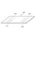
- FIG. 5shows another example of the parts to be registered by the registration unit 161.
- the component of this exampleis a flat plate-shaped component 210 made of a material such as metal or resin.
- the registered features depending on the random pattern peculiar to the individual componentare extracted from the entire surface region of the component 210.
- the registered featuresare not extracted from the back surface and the side surface of the component 210. That is, the predetermined region of the component 210 is the entire surface region.
- the image acquisition unit 1611 of the registration unit 161acquires one photographed image obtained by photographing the entire surface of the component 210 with the camera 110 according to the operation of the operator performing the registration work or by the autonomous operation of the registration unit 161. For example, if the camera 110 is an area camera and a surface image having a predetermined image resolution can be obtained even if the entire surface of the component 210 is included in the field of view of the camera and a surface image is obtained, the image acquisition unit 1611 can be used as a component by one imaging. The entire surface of 210 is photographed to acquire one photographed image.
- the image acquisition unit 1611divides the entire surface of the component 210 into several parts and divides the entire surface into several divided areas. Is individually photographed by the camera 110, and the photographed images of the plurality of divided regions are connected to acquire one photographed image covering the entire surface of the component 210.
- FIG. 5a total of three captured images of the left captured image 211, the center captured image 212, and the right captured image 213 are acquired, and the three captured images are connected to cover the entire surface of the component 210.
- An example of acquiring a single imageis shown.
- the image sizes of these three captured imagesare arbitrary, but here, as an example, it is assumed that the image sizes are as shown in FIG. That is, the captured images 211 to 213 on the left side, the center, and the right side all have vertical: 600 pixels and horizontal: 600 pixels.
- the image acquisition unit 1611may acquire the entire surface of the component 210 as a single captured image.
- the image combining unit 1612generates the registered image 214 from one image obtained by photographing the entire surface of the component 210 acquired by the image acquisition unit 1611.
- the image combining unit 1612uses a single image itself obtained by photographing the entire surface of the component 210 acquired by the image acquisition unit 1611 as the registered image 214.
- a registered image 214having a length of 600 pixels and a width of 1800 pixels is generated.
- the feature amount generation unit 1613extracts the feature amount depending on the random pattern existing in the image from the registered image 214 as the registered feature amount by the same method as the above-mentioned method, and stores it in the registration DB 152.
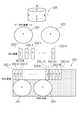
- FIG. 6shows yet another example of the parts to be registered by the registration unit 161.
- the component in this exampleis a columnar component 220 made of a material such as metal.
- the surface of the component 220is composed of a total of three surfaces, an upper surface, a lower surface, and a side surface. In this example, the registered features depending on the random pattern peculiar to each component are extracted from all the regions of these three surfaces. That is, the predetermined region of the component 220 is the entire surface.
- the image acquisition unit 1611 of the registration unit 161can obtain a predetermined image resolution according to the operation of the operator performing the registration work or by the autonomous operation of the registration unit 161 so that the entire surface of the component 220 can be obtained. Is captured by the camera 110 in a plurality of times to acquire a plurality of captured images. In the example shown in FIG. 6, a total of n + 2 captured images of the captured image 221 on the upper surface, the plurality of captured images 222-1 to 222-n on the side surface, and the captured image 223 on the lower surface are acquired.
- the image acquisition unit 1611acquires the captured image 221 of the upper surface by cutting out only the image region of the upper surface region from the image captured by the camera 110 from the front surface of the upper surface of the component 220. Further, the image acquisition unit 1611 acquires the captured image 223 on the lower surface in the same manner as the captured image 221 on the upper surface. Further, the image acquisition unit 1611 divides the side surface of the component 210 into n partial regions along the entire circumference, and cuts out only the image region of the partial region from the image taken by the camera 110 from the front of each partial region. By doing so, n photographed images 222-1 to 222-n in which different partial regions of the side surfaces are photographed are acquired. The number of divisions n is arbitrary.
- the image size of the above n + 2 captured imagesis arbitrary, but here, as an example, it is assumed that the image size is as shown in FIG. That is, the maximum width of the captured images 221 and 223 on the upper surface and the lower surface is 350 pixels. Further, the n captured images 222-1 to 222-n are all 250 pixels in the vertical direction and 92 pixels in the horizontal direction.
- the image acquisition unit 1611connects n photographed images 222-1 to 222-n obtained by photographing the side surface of the component 210, and covers the entire side surface of the component 220 over one round or more. To get.
- the image acquisition unit 1611may acquire one captured image from the line camera that covers the entire side surface of the component 220 over one round or more.
- the image combining unit 1612has a total of three captured images, that is, the captured image 221 on the upper surface acquired by the image acquisition unit 1611, the captured image 223 on the lower surface, and the captured image on the side surface covering the entire side surface over one round or more. Are arranged side by side to generate a registered image.
- the image combining unit 1612generates a registered image of a default size by pasting the three captured images on a background image of a predetermined size prepared in advance so as not to overlap each other.
- the background imageis an image in which the values of all pixels are predetermined values.
- the predetermined valuefor example, a zero value may be used. Alternatively, it may be a constant value other than the zero value as long as it does not affect the random pattern.
- the order and spacing of the images on the background imageare arbitrary. However, it is necessary to unify the orientation of the image to a predetermined orientation for the same captured image of the same type of parts. In addition, it is necessary that a plurality of captured images do not overlap each other.
- the captured image of the side surface covering the entire side surface obtained by connecting n captured images 222-1 to 222-n to the upper region of the background image over one round or moreis captured.
- the arrowsare attached so that the arrow points upward on the paper surface, and the captured images 221 and 223 on the upper and lower surfaces are attached to the lower region so that the arrows point upward on the paper surface.
- the area with dots on the registered image 224indicates a area of pixels having a zero value to which none of the captured images are attached.
- both ends of the expanded imageare continuous on the original object, but are separated on the expanded image. It ends up. That is, in the example of FIG. 6, the right side of the captured image 222-n and the left side of the captured image 222-1 are separated on the developed image even though they are continuous on the original component 220. Therefore, it becomes difficult to find a partial image matching the collated image that straddles the captured image 222-n and the captured image 222-1 from the registered image. Therefore, in the example of FIG.
- the copy images 222-1C to 222-4C of the photographed images 222-1 to 222-4are connected so that the left side of the photographed image 222-1 touches the right side of the photographed image 222-n. Therefore, one end of the continuous image is enlarged by 368 pixels, which is the image size of the four captured images 222-i.
- the enlarged sizemay be 368 pixels or less, or may be larger.
- the feature amount generation unit 1613extracts the feature amount depending on the random pattern existing in the image from the registered image 224 as the registered feature amount by the same method as the above-mentioned method, and stores it in the registration DB 152.
- FIG. 7shows an example of the format of the registration DB 152.
- the registration DB 152is composed of a plurality of entries having a one-to-one correspondence with the parts to be registered, and each entry is composed of each item of the part number, the registered feature amount, and the registered image size. ..
- a part numbersuch as a serial number assigned to the part to be registered is set.
- the name of the file in which the registered feature amount is recordedis set.
- the actual fileis stored in another area of the storage unit 150, a cloud storage (not shown), or the like.
- the item of registered image sizethe size of the registered image of the extraction source of the registered feature amount is set. In the example of FIG.
- the part number, the registered feature amount, and the size of the registered imageare stored for each part to be registered.
- the registered image size of all partsis configured to be unified to a predetermined specified value, it is not necessary to save the registered image size for each individual part, and only the specified value can be saved. good.
- each entry of the registration DB 152may be provided with other items in addition to the above-mentioned part numbers, registered feature amounts, and registered image size items.
- other itemsmay include product type, lot number, date of manufacture, product inspection result data, and the like.
- FIG. 8shows an example of a component to be collated by the collation unit 162.
- the component 300 in this exampleis the same type of component as the component 200 to be registered shown in FIG.
- the image acquisition unit 1621 of the collation unit 162takes an image of the right side surface of the component 300 from the front surface of the component 300 by the camera 110 according to the operation of the operator performing the collation work or by the autonomous operation of the collation unit 162.
- a photographed image 301 obtained by photographing the right side surface of the component 300 in a predetermined directionis acquired.
- the image acquisition unit 1621acquires the captured image 301 by cutting out only the image region of the right side surface from an image obtained by capturing the entire right side surface in a predetermined direction and at a predetermined pixel resolution by edge detection or the like.
- the image size of the captured image 301is arbitrary, but here, as an example, it is assumed that the vertical: 300 pixels and the horizontal: 400 pixels.
- the image size enlargement unit 1622determines whether or not the image size of the captured image 301 is smaller than the registered image size.
- the registered image sizeis constant regardless of the difference between individual parts, and the size is 600 pixels in the vertical direction and 1800 pixels in the horizontal direction.
- the image size enlargement unit 1622generates an image in which the captured image 301 is attached to one background image having the above registered image size and having a predetermined value such as a zero value for all pixels as a collation image. ..
- the place where the captured image 301 is attachedis arbitrary. However, the direction in which the captured image 301 is attached needs to be the same as that of the registered image.
- a collation image 302is generated in which the photographed image 301 is attached to the substantially central portion of the background image in the direction in which the arrow points toward the paper surface.
- the feature amount generation unit 1623extracts the feature amount depending on the random pattern existing in the image from the collation image 302 as the collation feature amount.
- the method by which the feature amount generation unit 1623 extracts the collation feature amount from the collation image 302is the same as the method by which the feature amount generation unit 1613 extracts the registered feature amount from the registered image 207.
- the determination unit 1624compares the collation feature amount with the registered feature amount for each registered feature amount stored in the registration DB 152, and obtains a score indicating the similarity between the collation feature amount and the registered feature amount. calculate. The details of the method in which the determination unit 1624 compares the two feature quantities and calculates the score representing the similarity will be described later.
- the determination unit 1624becomes the maximum score if the maximum score exceeds the preset determination threshold value among the above scores calculated for each registered feature amount stored in the registration DB 152. It is determined that the part to be registered and the part 300 specified by the part number stored in the registration DB 152 in association with the registered feature amount are the same individual. Further, if the maximum score does not exceed the determination threshold value, it is determined that the individual component identical to the component 300 does not exist in the registration DB 152.
- the image acquisition unit 1621has acquired the captured image 301 of the entire right side surface of the component 300.
- the image acquisition unit 1621may be a part of the right side surface of the component 300 or a surface other than the right side surface, that is, all or a part of any surface of the upper surface, the lower surface, the front side surface, the back side surface, and the left side surface.
- the collation unit 162performs the same operation as when the captured image 301 of the entire right side surface is acquired, so that the component 300 is stored in the registration DB 152 and the component 200 to be registered is any of the registered components 200. It can be determined whether or not it is the same individual as. The reason is that, for the component 200 to be registered, the registered feature amount unique to each component extracted from the photographed image is registered in advance in the registration DB 152 for each of the six surfaces.
- FIG. 9shows another example of the parts to be collated by the collating unit 162.
- the component 310 in this exampleis the same type of component as the component 210 to be registered shown in FIG.
- FIG. 9shows that the image acquisition unit 1621 of the collation unit 162 photographs the central portion of the upper surface of the component 310 from the front thereof by the camera 110 according to the operation of the operator performing the collation work or by the autonomous operation of the collation unit 162. It is assumed that the captured image 311 as shown is acquired.
- the image size of the captured image 311is arbitrary, but here, as an example, it is assumed that the vertical: 300 pixels and the horizontal: 600 pixels.
- the image size enlargement unit 1622determines whether or not the image size of the captured image 311 is smaller than the registered image size.
- the registered image sizeis constant regardless of the difference between individual parts, and the size is 600 pixels in the vertical direction and 1800 pixels in the horizontal direction.
- the image size enlargement unit 1622generates an image in which the captured image 311 is attached to one background image having the above registered image size and having a predetermined value such as zero value for all pixels as a collation image. ..
- the place where the captured image 311 is attachedis arbitrary. However, the direction in which the captured image 311 is attached needs to be the same as that of the registered image.
- a collation image 312is generated in which the photographed image 311 is attached to the central portion of the background image in the direction in which the arrow points toward the paper surface.
- the feature amount generation unit 1623uses the same method as the method of extracting the matching feature amount from the matching image 302 of FIG. 8 to obtain the matching feature amount depending on the random pattern existing in the image from the matching image 312. Extract as.
- the determination unit 1624compares the collation feature amount and the registered feature amount for each registered feature amount stored in the registration DB 152 by the same method as that described for the component 300 of FIG. A score representing the similarity between the collated features and the registered features is calculated. Then, the determination unit 1624 determines whether or not the component 310 is the same individual as any component stored in the registration DB 152 based on the score calculated for each registered feature amount, and outputs the result.
- the image acquisition unit 1621has acquired a part of the central portion of the upper surface of the component 310 as a captured image 311.
- the image acquisition unit 1621acquires a photographed image of an area other than the central portion of the upper surface of the component 310, for example, a region such as the left side or the right side of the upper surface by the operation of the operator performing the collation work, the upper surface
- the reasonis that for the component 210 to be registered, the registered feature amount peculiar to the individual component extracted from the captured image of the entire upper surface area is registered in advance in the registration DB 152.
- the image acquisition unit 1621acquires an image of the lower surface or an image of the side surface of the component 310, the individual identification of the component 310 cannot be performed.
- the reasonis that the features of the lower surface and the side surface of the component 210 to be registered are not registered in advance in the registration DB 152. Therefore, if there is a possibility that the lower surface or the side surface of the registration target component 210 may be photographed at the time of collation, the feature amount of the lower surface or the side surface may be registered in the registration DB 152.
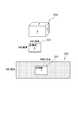
- FIG. 10shows yet another example of the parts to be collated by the collating unit 162.
- the component 320 in this exampleis the same type of component as the component 220 to be registered shown in FIG.
- the image acquisition unit 1621 of the collation unit 162takes a picture of a part of the side surface of the component 320 by the camera 110 according to the operation of the operator performing the collation work or by the autonomous operation of the collation unit 162. It is assumed that the captured image 321 is acquired.
- the image size of the captured image 321is arbitrary, but here, as an example, it is assumed that the image size is 250 pixels in the vertical direction and 368 pixels in the horizontal direction.
- the image size enlargement unit 1622determines whether or not the image size of the captured image 321 is smaller than the registered image size.
- the registered image sizeis constant regardless of the difference between individual parts, and the size is 600 pixels in the vertical direction and 1800 pixels in the horizontal direction.
- the image size enlargement unit 1622generates an image in which the captured image 321 is attached to one background image having the above registered image size and having a predetermined value such as zero value for all pixels as a collation image. ..
- the place where the captured image 321 is attachedis arbitrary. However, the direction in which the captured image 321 is attached needs to be the same as that of the registered image. In the example of FIG. 10, a collation image 322 is generated in which the photographed image 321 is attached to the central portion of the background image in the direction in which the arrow points toward the paper surface.
- the feature amount generation unit 1623uses the same method as the method of extracting the matching feature amount from the matching image 302 of FIG. 8 to obtain the matching feature amount depending on the random pattern existing in the image from the matching image 322. Extract as.
- the determination unit 1624compares the collation feature amount and the registered feature amount for each registered feature amount stored in the registration DB 152 by the same method as that described for the component 300 of FIG. A score representing the similarity between the collated features and the registered features is calculated. Then, the determination unit 1624 determines whether or not the component 320 is the same individual as any component stored in the registration DB 152 based on the score calculated for each registered feature amount, and outputs the result.
- the image acquisition unit 1621has acquired a part of the side surface of the component 320 as a captured image 321.
- the image acquisition unit 1621acquires a photographed image of a portion other than the above on the side surface of the component 320, the upper surface of the component 320, and the lower surface of the component 320
- the same operation as when the photographed image 321 is acquiredis performed by the collation unit.
- FIG. 11is a block diagram showing an example of the determination unit 1624.
- the determination unit 1624 of this exampleincludes a frequency feature synthesis unit 16241, a square wave determination unit 16242, and an information presentation unit 16243.
- the frequency feature synthesis unit 16241is configured to calculate a normalized cross-power spectrum of the collation feature amount and the registered feature amount for each registered feature amount registered in the registration DB 152. Further, the frequency feature synthesis unit 16241 is configured to quantize the calculated normalized cross-power spectrum and convert the value of each element into binary or ternary data.
- the square wave determination unit 16242is configured to calculate a score indicating to some extent that the quantized cross power spectrum is a square wave having a single period for each quantized cross power spectrum obtained from the frequency feature synthesis unit 16241. ing. Further, the rectangular wave determination unit 16242 is configured to collate the collated image with the registered image based on the calculated score. For example, when the best score among the plurality of scores calculated for the plurality of quantized cross-power spectra corresponding to the plurality of registered images satisfies a predetermined reference value, the square wave determination unit 16242 sets the collated image and the above-mentioned best.
- the rectangular wave determination unit 16242derives a collation result indicating that the registered image partially matching the collated image does not exist in the registered DB 152.
- the information presentation unit 16243is configured to present the collation result obtained from the rectangular wave determination unit 16242.
- the collation image and the registered imagebe two images f (n 1 , n 2 ) and an image g (n 1 , n 2 ) of N 1 ⁇ N 2 pixels.
- M 1 and M 2are positive integers
- the first frequency feature F (k 1 , k 2 ) obtained by two-dimensional discrete Fourier transform of the image f (n 1 , n 2 ) and the image g (n 1 , n 2 )are two-dimensional discrete Fourier.
- the second frequency feature G (k 1 , k 2 ) obtained by conversionis given by Equations 1 and 2 shown in FIG.
- the first frequency feature F (k 1 , k 2 )corresponds to the matching feature quantity
- the second frequency feature G (k 1 , k 2 )corresponds to the registered feature quantity.
- W N1 and W N2are rotation factors and are given by Equations 3 and 4 shown in FIG.
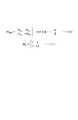
- a F (k 1 , k 2 ) and AG (k 1 , k 2 )are amplitude spectra (amplitude components), and ⁇ F (k 1 , k 2 ) and ⁇ G (k 1 , k 2 ) are phases. Represents each spectrum (phase component).
- ⁇ n1 and n2represent addition over the entire index as shown in Equation 5 of FIG.
- FIG. 13is an image of the amplitude components A F (k 1 , k 2 ) and A G (k 1 , k 2 ), the phase components ⁇ F (k 1 , k 2 ) and ⁇ G (k 1 , k 2 ). An example is shown.
- FIG. 14is a block diagram showing an example of the frequency feature synthesis unit 16241.
- the frequency feature synthesis unit 16241 of this exampleis composed of a synthesis unit 162411 and a quantization unit 162412.
- the synthesis unit 162411displays a normalized cross power spectrum R (k 1 , k 2 ) of the first frequency feature F (k 1 , k 2 ) and the second frequency feature G (k 1 , k 2 ) in FIG. It is calculated by the formula 6 shown in.
- the overline G (k 1 , k 2 )is the complex conjugate of the second frequency feature G (k 1 , k 2).
- ⁇ F (k 1 , k 2 ) ⁇ ⁇ G (k 1 , k 2 )is a phase difference spectrum between the first frequency feature and the second frequency feature.
- the frequency feature synthesizer 16241is for each element of the complex conjugate of the first frequency feature F (k 1 , k 2 ) and the second frequency feature G (k 1 , k 2).
- the normalized cross power spectrumis calculated by obtaining the cross power spectrum, which is the product, and further normalizing it with its absolute value.
- the image g (n 1 , n 2 )is an image in which the image f (n 1 , n 2 ) is translated by ( ⁇ 1 , ⁇ 2 ).
- the normalized cross power spectrum R (k 1 , k 2)is used.
- k 2 )is expressed as a complex sine wave with a single period for each dimension (every k 1 and k 2).
- the normalized cross power spectrum R (k 1 , k 2 )is used. Is not a complex sine wave with a single period for each dimension. Further, when the two image pairs to be collated have a correlation in the element corresponding to a specific band on the frequency domain, the normalized cross of the frequency features F (k 1 , k 2 ) and G (k 1 , k 2).
- the power spectrum R (k 1 , k 2 )is a pattern in which a complex sine wave having a single period partially appears.
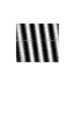
- FIG. 17shows an example of an image of the normalized cross power spectrum R (k 1 , k 2) of the same image pair.
- the normalized cross-power spectrum of the same image pairis an image like a wave having a single period when the bright part is regarded as a mountain and the dark part is regarded as a valley.
- the two image pairs to be collatedhave a correlation in an element corresponding to a specific band on the frequency domain, the normalized cross-power spectrum of the partially matching image pairs will result in a wave-like image as a whole. Appears partially without.
- the quantization unit 162412quantizes each element of the normalized cross-power spectrum obtained by the synthesis unit 162411 into binary or ternary data.
- the method of performing such quantizationis arbitrary. For example, the following quantization method may be used.
- the value (composed of the real part and the imaginary part) of each element of the normalized cross power spectrum obtained by the synthesis unit 162411is predetermined among the real part and the imaginary part of each element.
- the sidewith a binary or ternary quantized value.
- the value of a certain element Ube A + Bj.
- a and Bare real numbers, and j is an imaginary unit.
- the element Uis quantized into a binary value, for example, if A ⁇ 0, A + Bj is converted to “+1”, and if A ⁇ 0, A + Bj is converted to “-1”.
- the real partis quantized into two values based on the sign of the real number A, but the imaginary part may be quantized into two values based on the sign of the real number B.
- the real partis quantized into two values based on the sign of the real number A, but the imaginary part may be quantized into two values based on the sign of the real number B.
- the quantization unit 162412expresses each element of the normalized cross-power spectrum obtained by the synthesis unit 162411 as 1-bit or 2-bit data.
- quantization unit 162412quantizes each element of the normalized cross-power spectrum into binary or ternary data is as follows.
- each element of the normalized cross-power spectrum R(k 1 , k 2 ) are calculated as real values (floating point numbers), and many bits are required to represent each element (for example,). , 64bit data for double precision floating point, 32bit data for single precision floating point). Accurately determine the amount of misalignment between images In the application of alignment between images, it is important to obtain the normalized cross power spectrum as a complex sine wave with as little error as possible and to obtain the period of the complex sine wave accurately. It becomes. On the other hand, in an application for determining whether or not two images are the same as in the embodiment of the present invention, it is not necessary to accurately calculate the normalized cross power spectrum as a complex sine wave.
- each element of the normalized cross-power spectrum obtained by the synthesis unit 162411is quantized into binary or ternary data by the quantization unit 162241.
- FIG. 18shows an example of an image in which the normalized cross-power spectrum R (k 1 , k 2 ) of the same image pair is quantized into binary data.
- the normalized cross-power spectrumwhich is the real number data expressed in 32 bits or 64 bits, is quantized into two values (1 bit) or three values (2 bits) and the amount of data is reduced, the input images are separated. It is possible to determine whether or not there is a correlation between the two without degrading the accuracy. That is, it is possible to discriminate between the same image pair having a correlation and a different image pair having no correlation with a small amount of data without impairing the accuracy.
- the square wave determination unit 16242is a square wave having a single period with respect to the normalized cross-power spectrum whose elements are quantized into binary or ternary values calculated by the frequency feature synthesis unit 16241. The degree of whether it is is quantified and output as a score.
- FIG. 19is a block diagram showing an example of the rectangular wave determination unit 16242.
- the rectangular wave determination unit 16242 of this exampleis composed of, for example, an orthogonal transformation unit 162421 that performs orthogonal transformation using an Adamard matrix.
- the orthogonal transform unit 162421is configured to perform orthogonal transform using a Hadamard matrix on a normalized cross-power spectrum quantized into binary or ternary values, and output the maximum value of the output as a score. There is.
- the quantized normalized cross-power spectrumis a square wave having a single period, a sharp peak value appears in the period at the output of the orthogonal transform unit 162421.
- the quantized normalized cross-power spectrumis not a square wave with a single period, no sharp peak value will appear at the output of the orthogonal transform unit 162421.
- the maximum value of the output of the orthogonal transform unit 162421can be a score in which the quantized normalized cross-power spectrum represents a certain degree with a square wave having a single period.
- the orthogonal transform unit 162421collates images based on the calculated score.
- Equation 12The orthogonal transformation using the Hadamard matrix performed by the orthogonal transform unit 162421 is described by Equation 12 in FIG.
- H Nis the Hadamard matrix
- Xis the N ⁇ N input signal (quantized cross-power spectrum)
- Yis the N ⁇ N output signal (score).
- the operation of Equation 12is executed by a combination of logical operation such as exclusive OR (XOR), bit counting, and addition / subtraction in the case of a normalized cross-power spectrum quantized into two values (“+1” and “-1”). Therefore, high-speed processing is possible.
- the operation of Equation 12does not perform the operation on the element having the value of “0”. Since it can be executed by a combination of logical operations such as exclusive OR (XOR), bit counting, and addition / subtraction for the elements of "+1" and "-1”, high-speed processing is possible.
- FIG. 22is a block diagram showing another example of the rectangular wave determination unit 16242.
- the rectangular wave determination unit 16242 of this exampleincludes a circulation shift processing unit 162422 and a similarity calculation unit 162423.
- the cyclic shift processing unit 162422inputs a normalized cross-power spectrum (hereinafter referred to as pre-circular shift data) in which each element is quantized into binary or ternary values, and cyclically shifts the elements by a rotate operation without carry or the like. It is configured to output the quantized cross-power spectrum (hereinafter referred to as the data after cyclic shift). Further, the circulation shift processing unit 162422 is configured to output a plurality of post-circulation shift data having different circulation shift amounts by variously changing the circulation shift amount.
- pre-circular shift dataa normalized cross-power spectrum
- pre-circular shift dataquantized cross-power spectrum
- the circulation shift processing unit 162422is configured to output a plurality of post-circulation shift data having different circulation shift amounts by variously changing the circulation shift amount.
- the similarity calculation unit 162423inputs the pre-circular shift data and a plurality of post-circular shift data having different amounts of the circular shift, and calculates a plurality of similarities between the pre-circular shift data and the plurality of post-circular shift data. It is configured. Further, the similarity calculation unit 162423 is configured to output the maximum similarity among the calculated plurality of similarity as a score. The similarity calculation unit 162423 collates images based on the calculated score.
- the pre-circular shift datais a square wave having a single period
- the rectangular wave having the same single period as the pre-circular shift datais circularly shifted. It appears periodically as post-data.
- the pre-circular shift datais not a square wave having a single period, even if the pre-circular shift data is cyclically shifted to various shift amounts by the circular shift processing unit 162422, the same pattern of circular shift as the pre-circular shift data is performed. No post-data appears.
- the similarity calculation between the pre-circular shift data and the post-circular shift datais repeated while changing the amount of the cyclic shift, and the maximum value of the similarity is used as the score, so that the quantized cross-power spectrum has a single period. It is possible to calculate a score that represents a certain degree with the square wave that it has.
- the above-mentioned circular shift processing unit 162422can be implemented by a bit shift operation. Further, the similarity calculation unit 162423 described above can be implemented by exclusive OR (XOR) and bit count calculation for calculating the Hamming distance between data before and after the cyclic shift. Therefore, it is possible to perform a calculation faster than the autocorrelation operation on real number data.
- XORexclusive OR
- FIG. 23is a block diagram showing still another example of the rectangular wave determination unit 16242.
- the square wave determination unit 16242 of this exampleincludes a square wave pattern storage unit 162424 and a similarity calculation unit 162425.
- the rectangular wave pattern storage unit 162424is configured to store a plurality of reference rectangular wave patterns.
- One reference square wave patternis a quantized cross-power spectrum in which each element of the normalized cross-power spectrum of the same image pair having a certain amount of misalignment is quantized into two or three values.
- the plurality of reference rectangular wave patterns stored in the rectangular wave pattern storage unit 162424differ from each other in the amount of misalignment.
- the similarity calculation unit 162425is configured to input a normalized cross-power spectrum (hereinafter referred to as a matching square wave pattern) in which each element is quantized into binary or ternary values from the frequency feature synthesis unit 16241. ing. Further, the similarity calculation unit 162425 is configured to input a plurality of reference rectangular wave patterns from the rectangular wave pattern storage unit 162424. Further, the similarity calculation unit 162425 calculates a plurality of similarity between the input matching square wave pattern and the plurality of reference square wave patterns, and outputs the maximum similarity among the plurality of similarity as a score. It is configured. The degree of similarity between the matching square wave pattern and the reference square wave pattern can be determined, for example, by calculating the Hamming distance. The similarity calculation unit 162425 collates images based on the calculated score.
- a normalized cross-power spectrumhereinafter referred to as a matching square wave pattern
- the similarity calculation unit 162425is configured to input a plurality of reference rectangular wave patterns from the
- the normalized cross power spectrumbecomes a square wave pattern having a single period, and the period corresponds to the amount of misalignment between the two images. Therefore, it is possible to infer the pattern of the rectangular wave that occurs when there is a correlation by obtaining the range of the repetition error of the amount of misalignment during shooting.
- These patternsare stored in the square wave pattern storage unit 162424 as a reference square wave pattern in advance, the similarity calculation unit 162425 calculates the humming distance from the matching square wave pattern, and the matching square wave pattern is calculated based on the distance. Calculates and discriminates a score that represents a certain degree with a square wave having a single period.
- the collation image and the registered imagecan be collated at high speed.
- the reasonis that the normalized cross-power spectrum of the frequency feature of the collated image and the frequency feature of the registered image is quantized, and the score that the quantized cross-power spectrum represents to some extent with a single-period square wave is calculated.
- the collated image and the registered imageare collated based on the score. That is, in the determination unit 1624, in order to quantize each element of the normalized cross power spectrum obtained by the synthesis unit 162411 into binary or ternary data by the quantization unit 162241, the normalized cross power spectrum is quantized.
- the amount of data processed by the square wave determination unit 16242can be significantly reduced as compared with the method of determining whether or not the normalized cross power spectrum is a complex sine wave having a single period.
- the frequency feature synthesizer 16241quantizes each element of the normalized cross-power spectrum of the frequency feature of the collated image and the frequency feature of the registered image into binary or ternary data.
- the cross power spectrumwas calculated. However, after calculating the cross power spectrum between the frequency feature of the collated image and the frequency feature of the registered image, the sign (+,-) of each element of the cross power spectrum is used to indicate "+1, -1" without normalizing with the amplitude component. , Or even if it is converted to "+1, 0, -1", the same quantization cross power spectrum as described above can be calculated.
- the frequency feature synthesizing unit 16241calculates the cross-power spectrum of the frequency feature of the collated image and the frequency feature of the registered image, and then sets the code (+,-) of at least one of the real part and the imaginary part of each element. Based on this, it may be configured to be quantized into binary or ternary values.
- the collation unit 162indicates the degree to which a partial image similar to the collation image obtained by photographing a part of the predetermined area of the part to be collated exists in the registered image obtained by photographing the predetermined area of the part to be registered. This is to calculate a score and determine whether or not the part to be collated is the same as the part to be registered based on the score. That is, at the time of collation, it is not necessary to photograph the entire region of the predetermined region of the component, and it is sufficient to photograph a part of the predetermined region.
- the discriminating abilitywhich is a degree to which different parts can be discriminated.
- the reasonis that a part of the specific area of the part to be collated is equal to or larger than the minimum area where the random pattern necessary for ensuring the discriminating ability required to discriminate different parts for as many individual parts as possible can be obtained. This is because it is an area of the area of.
- the present embodimentit is possible to determine at high speed whether or not the part to be collated is the same as the part to be registered as compared with the individual identification method related to the present invention. The reason is as follows.
- the individual identification method related to the present inventionfor example, in the collation of the rectangular parallelepiped part 300 shown in FIG. 8, a total of 6 captured images of the upper surface, the lower surface, the front side surface, the back side surface, the left side surface, and the right side surface are acquired. , It is necessary to compare the captured images of the same surface for each part to be registered stored in the registration DB 152. However, it may not be possible to accurately associate each surface of the part 300 to be collated with each surface of the component 200 to be registered on a one-to-one basis. For example, the upper surface and the lower surface of a rectangular parallelepiped-shaped component have the same shape and the same size, and are indistinguishable.
- the photographed image of that surfacemust be compared with a plurality of surfaces instead of one surface of the component to be registered. There are times when you have to. As a result, the screen size to be compared increases, and the time required for the comparison process increases.
- Comparison with (pixels)Comparison between the photographed image of the lower surface of the component 300 (600 pixels x 400 pixels) and the photographed image of the lower surface of the component 200 (600 pixels x 400 pixels) (5) Photographing the front side surface of the component 300 Comparison of the image (600 pixels x 300 pixels) and the captured image (600 pixels x 300 pixels) on the front side of the component 200 (6) The captured image (600 pixels x 300 pixels) on the front side of the component 300 and the back of the component 200 Comparison with the side shot image (600 pixels x 300 pixels) (7) The back side shot image (600 pixels x 300 pixels) of the component 300 and the front side shot image (600 pixels x 300 pixels) of the component 200 Comparison (8) Comparison between the photographed image of the back side of the component 300 (600 pixels x 300 pixels) and the photographed image of the back surface of the component 200 (600 pixels x 300 pixels) (9) The photographed image of the left side of the component 300 ( Comparison between (400 pixels x 300 pixels) and the captured image (400 pixels x 300 pixels) on the left
- the registered feature amount extracted from the registered imageobtained by arranging the captured images acquired from a plurality of different surfaces of the parts to be registered to form one image and the acquired from any one of the above-mentioned plurality of surfaces. Based on the cross-power spectrum calculated by frequency-synthesizing the registered feature amount extracted from the magnified collation image of the image, it is determined whether or not the collation target component is the same as the registration target component. In this way, regardless of the number of captured images of the parts to be registered, by collating one registered image with one collation image, each of the plurality of captured images of the parts to be registered are photographed. As compared with the method of repeating collating with the collated image a plurality of times, the overhead can be reduced.
- the reason why there is no problem in collation even if the photographed images acquired from a plurality of different surfaces of the parts to be registered are arranged and one registered image is arrangedis that the random pattern existing on the surface of the individual parts is literally. This is because it is a random pattern and it is extremely difficult to intentionally create the same one. That is, even if images of different regions of parts are arbitrarily arranged and a predetermined value such as a zero value is inserted between the images, the same random pattern as the random pattern existing on the surface of another individual is created. This is because there is no such thing.
- the registration unit 161stores, for each component to be registered, the feature amount extracted from the photographed image of the predetermined area of the component in the registration DB 152.
- the registration unit 161may be configured to store the registered image of the feature amount extraction source in the registration DB 152 instead of storing the feature amount in the registration DB 152.
- the feature amount generation unit 1613may be omitted.
- the determination unit 1624 of the collation unit 162collates the registered feature amount to be compared with the collation feature amount generated by the feature amount generation unit 1623 from the registered image stored in the registration DB 152 by using the feature amount generation unit 1623. It may be configured to generate at times.
- the determination unit 1624 of the collation unit 162compares the feature amount extracted from the collation image with the feature amount extracted from the registered image to the extent that a partial image similar to the collation image exists in the registered image. The score representing was calculated. However, the determination unit 1624 of the collation unit 162 compares the collation image and the registered image by using a technique such as template matching to obtain a score indicating the degree to which a partial image similar to the collation image exists in the registered image. It may be configured to calculate.
- one individual identification device 100includes a registration unit 161 and a collation unit 162.
- FIG. 24is a block diagram of the individual identification device 400 according to the second embodiment of the present invention.
- the individual identification device 400includes a camera 410, a communication I / F unit 420, an operation input unit 430, a screen display unit 440, a storage unit 450, and an arithmetic processing unit 460.
- the camera 410, the communication I / F unit 420, the operation input unit 430, and the screen display unit 440are the camera 110, the communication I / F unit 120, the operation input unit 130, and the screen display unit of the individual identification device 100 of FIG. It is configured in the same way as 140.
- the storage unit 450is composed of a storage device such as a hard disk or a memory, and is configured to store processing information and a program 451 required for various processes in the arithmetic processing unit 460.
- the program 451is a program that realizes various processing units by being read and executed by the arithmetic processing unit 460, and is transmitted from an external device or recording medium (not shown) via a data input / output function such as the communication I / F unit 420. It is read in advance and saved in the storage unit 450.
- the main processing information stored in the storage unit 450is the registration DB (database) 452.
- the registration DB 452is a database that stores a registered image unique to each part generated from an image of the part to be registered by the camera 410 in association with the individual number.
- the arithmetic processing unit 460has a processor such as an MPU and its peripheral circuits, and by reading and executing the program 451 from the storage unit 450, the hardware and the program 451 cooperate with each other to realize various processing units. It is configured as follows.
- the main processing units realized by the arithmetic processing unit 460are the registration unit 461 and the collation unit 462.
- the registration unit 461is configured to generate a feature amount unique to each part from an image of the part to be registered, associate the generated feature amount with the individual number of the part, and register the feature amount in the registration DB 452.
- the registration unit 461has an image acquisition unit 4611, a feature amount generation unit 4612, and an image combination unit 4613.
- the image acquisition unit 4611is configured in the same manner as the image acquisition unit 1611 in FIG. That is, the image acquisition unit 4611 is configured to acquire a plurality of images taken by dividing a predetermined area of the component into a plurality of times as necessary for each component to be registered from the camera 410.
- the feature amount generation unit 4612is configured to extract a feature amount depending on a random pattern existing in the image from the captured image generated by the image acquisition unit 4611 for each component to be registered. Specifically, the feature amount generation unit 4612 acquires, as a feature amount, a Fourier-Mellin feature image obtained by subjecting the photographed image to a Fourier-Mellin transform for each photographed image. For example, the feature amount generation unit 4612 calculates a two-dimensional amplitude spectrum as a result of converting the captured image into a frequency domain by performing frequency conversion (for example, discrete Fourier transform). Next, the feature amount generation unit 4612 performs polar coordinate transformation or logarithmic polar coordinate transformation on the two-dimensional amplitude spectrum to calculate a Fourier merin feature image. Changes in magnification and rotation of the original captured image are converted into changes in translation in the Fourier-merin feature image.
- the image combining unit 4613is configured to generate a registered image as one image by arranging the Fourier merin feature images for each captured image generated by the feature amount generation unit 4612 for each component to be registered. .. Further, the image combining unit 4613 is configured to register the registered image in the registration DB 452 in association with the individual number of the component for each component to be registered.
- the collation unit 462calculates a score indicating the degree to which a partial image similar to an image obtained by capturing at least a part of a predetermined area of the part to be collated exists in the captured image of the predetermined area of the component to be registered. It is configured in. Further, the collation unit 462 is configured to determine whether or not the collation target component is the same as the registration target component based on the above score.
- the collation unit 462includes an image acquisition unit 4621, a feature amount generation unit 4622, an image size enlargement unit 4623, and a determination unit 4624.
- the image acquisition unit 4621is configured to acquire an image obtained by capturing at least a part of a predetermined area of the component to be collated from the camera 410.
- at least a part of the predetermined areais an area having an area equal to or larger than the minimum area where a random pattern necessary for ensuring discrimination ability, which is a degree capable of distinguishing different parts, can be obtained for as many individual parts as possible. Is desirable.
- the feature amount generation unit 4622is configured to extract a feature amount depending on a random pattern existing in the image from the captured image acquired by the image acquisition unit 4621. Specifically, the feature amount generation unit 4622 is configured to generate a Fourier mellin and a feature image by performing a Fourier-Mellin transform on the captured image.
- the image size enlargement unit 4622When the size of the Fourier merin feature image generated by the feature amount generation unit 4622 is smaller than the size of the registered image, the image size enlargement unit 4622 generates a collation image by enlarging the size to the same size as the registered image. It is configured as follows. For example, the image size enlargement unit 4622 converts the Fourier merin feature image generated by the feature amount generation unit 4622 into a single background image having the same size as the registered image and having a predetermined value such as zero value for all pixels. It is configured to generate the pasted composite image as a collation image.
- the image size enlargement unit 4622sets the size of the Fourier / merin feature image generated by the feature amount generation unit 4622 by concatenating pixels having a predetermined value such as a zero value to the same size as the registered image. It is configured to generate a magnified image.
- the determination unit 4624calculates a score indicating the degree of similarity between the collation image generated by the image size enlargement unit 4623 and the registered image for each registered image stored in the registration DB 452, and collates based on the score. It is configured to determine which registration target component is the same as the target component.
- the determination unit 4624may calculate the above score by the same method as the determination unit 1624 of FIG. Alternatively, the determination unit 4624 synthesizes the collated image and the registered image to calculate a cross power spectrum, and determines a score indicating to some extent by a wave having a single period in the cross power spectrum between the collated image and the registered image. It may be calculated as a score representing similarity (see, for example, Patent Document 2).
- the determination unit 4624calculates the correlation value map by performing an inverse Fourier transform on the cross power spectrum, calculates the presence / absence of the maximum value peak in the correlation value map, and calculates the evaluation value of the sharpness of the peak, and finally. A score indicating the similarity between the collated image and the registered image may be calculated. Further, the determination unit 4624 is configured to display the determination result on the screen display unit 440 and / and output it to an external device through the communication I / F unit 420.
- FIG. 25is a flowchart showing an example of the registration operation of the individual identification device 400.
- FIG. 26is a flowchart showing an example of the collation operation of the individual identification device 400.
- the image acquisition unit 4611acquires a plurality of images taken by dividing a predetermined area of the component into a plurality of times as necessary for each component to be registered from the camera 410.
- the feature amount generation unit 4612calculates a Fourier merin feature image depending on a random pattern existing in the image from the captured image generated by the image acquisition unit 4611 for each component to be registered (step S12). ..
- the image combining unit 4613generates a registered image as one image by arranging the Fourier merin feature images for each captured image generated by the feature amount generation unit 4612 for each component to be registered, and generates a registered image of the component. It is saved in the registration DB 452 in association with the individual number (step S13). This completes the registration operation.
- the image acquisition unit 4621acquires an image obtained by capturing at least a part of a predetermined area of the component to be collated from the camera 410 (step S14).
- the feature amount generation unit 4622generates a Fourier merin feature image from the captured image acquired by the image acquisition unit 4621 (step S15).
- the image size enlargement unit 4622enlarges the Fourier merin feature image generated by the feature amount generation unit 4622 to the same size as the registered image to generate a collation image (step S16).
- the determination unit 4624calculates a score representing the degree of similarity between the collated image generated by the image size enlargement unit 4623 and the registered image for each registered image stored in the registration DB 452 (step S17). Next, the determination unit 4624 determines whether or not the collation target component is the same as any registration target component based on the above score (step S18). Next, the determination unit 4624 outputs the determination result (step S19).
- FIG. 27shows an example of the part 400 to be registered by the registration unit 461.
- the component 400 in this exampleis the same component as the component 200 shown in FIG.
- a Fourier merin feature imagethat depends on a random pattern peculiar to an individual component is extracted from all the regions of the six surfaces of the component 400. That is, the predetermined area of the component 400 is the entire six surfaces.
- the image acquisition unit 4611 of the registration unit 461captures each surface of the component 400 from the front with the camera 410 according to the operation of the operator performing the registration work or by the autonomous operation of the registration unit 461. Acquire the captured image.
- the feature amount generation unit 4612generates a Fourier merin feature image of each surface from the captured image of each surface. That is, as shown in FIG. 27, the feature amount generation unit 4612 has the Fourier merin feature image 501 of the upper surface photographed image, the Fourier merin feature image 502 of the lower surface photographed image, and the Fourier merin feature of the front side surface photographed image.
- An image 503, a Fourier merin feature image 504 of the back side captured image, a Fourier merin feature image 505 of the left side captured image, and a Fourier merin feature image 506 of the right side captured imageare generated.
- a thick arrowis drawn on the Fourier merin feature image. This thick arrow is a convenient symbol for orienting the Fourier Melin feature image. The same applies to the thick arrows in other drawings such as FIG. 28.
- the image combining unit 4613arranges the above six Fourier / merin feature images, generates a registered image, and stores the registered image in the registered DB 152.
- the order and spacing of arrangementare arbitrary.
- the Fourier merin feature images 501, 502, 503, and 504are arranged in a row so as to be in contact with each other and the arrows point to the left of the paper, and are arranged in two rows at one end.
- the registered image 507is generated by arranging the Fourier merin feature images 505 and 506 in the direction in which the arrows point toward the paper surface.
- FIG. 28shows another example of the parts to be registered by the registration unit 461.
- the component 510 in this exampleis the same component as the component 210 shown in FIG.
- a Fourier merin feature imagethat depends on a random pattern peculiar to an individual component is extracted from the entire surface region of the component 510. That is, the predetermined region of the component 510 is the entire surface.
- the image acquisition unit 4611 of the registration unit 461acquires one photographed image 511 in which the entire surface of the component 510 is photographed by the camera 410 according to the operation of the operator performing the registration work or by the autonomous operation of the registration unit 461.
- the feature amount generation unit 4613generates a Fourier / merin feature image from the captured image 511 by the same method as the above-described method.
- the image combining unit 4613has only one Fourier / merin feature image generated by the feature amount generation unit 4613, for example, the Fourier / merin feature image itself is set as the registered image 512 and stored in the registration DB 452.
- FIG. 29shows yet another example of the parts to be registered by the registration unit 461.
- the component 520 in this exampleis the same component as the component 220 in FIG.
- the surface of the component 520is composed of a total of three surfaces, an upper surface, a lower surface, and a side surface.
- a Fourier-merin feature imageis extracted from all the regions of these three surfaces. That is, the predetermined region of the component 520 is the entire surface.
- the image acquisition unit 4611 of the registration unit 461is a side surface that covers the entire side surface of the image 521 of the upper surface of the component 520 by the camera 410 according to the operation of the operator performing the registration work or by the autonomous operation of the registration unit 461. A total of three captured images, the captured image 522 and the captured image 523 on the lower surface, are acquired.
- the feature amount generation unit 4613generates Fourier-merin feature images 524, 525, and 526 from the captured images 521, 522, and 523, respectively, by the same method as described above.
- the image combining unit 4612generates a registered image 527 in which the above three Fourier merin feature images 524 to 526 are arranged side by side to form one image.
- the image combining unit 4612generates a registered image of a default size by pasting the three Fourier merin feature images on a background image of a predetermined size prepared in advance so as not to overlap each other.
- the background imageis an image in which the values of all pixels are predetermined values.
- the predetermined valuefor example, a zero value may be used. Alternatively, it may be a constant value other than the zero value as long as it does not affect the random pattern.
- the side surface Fourier melin feature image 527is attached to the upper side of the background image, and the upper surface and lower surface Fourier merin feature images 524 and 526 are attached to the lower region.
- the area with dots on the registered image 527indicates the area of the pixel having a zero value to which none of the captured images is attached.
- the order and spacing of arranging the three Fourier merin feature images 524 to 526 on the background imageis arbitrary. However, it is necessary to unify the orientation of the Fourier / merin feature image to the orientation determined for each of the same captured images of the same type of parts. In addition, it is necessary that a plurality of Fourier / merin feature images do not overlap each other.
- FIG. 30shows an example of a part to be collated by the collating unit 462.
- the component 600 in this exampleis the same type of component as the component 500 to be registered shown in FIG. 27.
- the image acquisition unit 4621 of the collation unit 462may photograph the right side surface of the component 600 from the front thereof in an arbitrary direction by the camera 410 according to the operation of the operator performing the collation work or by the autonomous operation of the collation unit 462.
- a photographed image 601 obtained by photographing the right side surface of the component 600 in an arbitrary direction as shown in 30is acquired.
- the feature amount generation unit 4622generates a Fourier / merin feature image 602 from the captured image 601.
- the image size enlargement unit 4623enlarges the Fourier-merin feature image 602 so that it has the same size as the registered image, and generates a collation image 603.
- the image size enlargement unit 4622has an image in which the Fourier merin feature image 602 is attached to one background image having the same size as the registered image size and having a predetermined value such as zero value for all pixels. It is generated as a collation image 603.
- the place where the Fourier Melin feature image 602 is attachedis arbitrary. However, the direction in which the Fourier-merin feature image 602 is attached needs to be the same as that of the registered image. In the example of FIG. 30, a Fourier merin feature image 602 is attached to a substantially central portion of the background image so that a thick arrow points toward the paper surface.
- the determination unit 4624compares the collation image with the registered image for each registered image stored in the registration DB 452 by the same method as the determination unit 1624, and thereby, the similarity between the collation image and the registered image. Calculate the score that represents.
- the determination unit 4624sets the maximum score (maximum cross-correlation) among the above scores calculated for each registered image stored in the registration DB 452 if it exceeds a preset determination threshold value. It is determined that the part to be registered and the part 600 specified by the part number stored in the registration DB 452 in association with the registered image having the score of 1 are the same individual. Further, if the maximum score does not exceed the determination threshold value, it is determined that the individual component identical to the component 600 does not exist in the registration DB 152.
- the image acquisition unit 4621has acquired the captured image 601 of the entire right side surface of the component 600.
- the image acquisition unit 4621may use a part of the right side surface of the component 600 or a surface other than the right side surface, that is, all or a part of any surface of the upper surface, the lower surface, the front side surface, the back side surface, and the left side surface.
- the collation unit 462performs the same operation as when the captured image 601 of the entire right side surface is acquired, so that the component 600 is stored in the registration DB 452. It is possible to determine whether or not the individual is the same as. The reason is that for the component 500 to be registered, the registered image is pre-registered in the registration DB 452 as one image by arranging the Fourier merin feature images extracted from the captured images of each of the six surfaces. Is.
- FIG. 31shows another example of the parts to be collated by the collation unit 462.
- the component 610 in this exampleis the same type of component as the component 510 to be registered shown in FIG. 28.
- the image acquisition unit 4621 of the collation unit 462captures the central portion of the upper surface of the component 610 from the front thereof in an arbitrary direction by the camera 410 according to the operation of the operator performing the collation work or by the autonomous operation of the collation unit 462. , It is assumed that the captured image 611 as shown in FIG. 31 is acquired. Next, the feature amount generation unit 4622 generates a Fourier-merin feature image 612 from the captured image 611.
- the image size enlargement unit 4623enlarges the Fourier-merin feature image 612 so that it has the same size as the registered image, and generates a collation image 613.
- the image size enlargement unit 4622has an image in which the Fourier merin feature image 612 is attached to one background image having the same size as the registered image size and having a predetermined value such as zero value for all pixels. It is generated as a collation image 613.
- the place where the Fourier Melin feature image 612 is pastedis arbitrary. However, the direction in which the Fourier-merin feature image 612 is attached needs to be the same as that of the registered image. In the example of FIG. 31, a Fourier merin feature image 612 is attached to the central portion of the background image so that a thick arrow points toward the paper surface.
- the determination unit 4624calculates a score indicating the similarity between the collated image and the registered image by comparing the collated image and the registered image for each registered image stored in the registered DB 452. Then, the determination unit 4624 determines whether or not the component 610 is the same individual as any component stored in the registration DB 452 based on the score calculated for each registered image, and outputs the result.
- the image acquisition unit 4621acquired a part of the central portion of the upper surface of the component 610 as a captured image 611.
- the image acquisition unit 4621acquires a photographed image of an area other than the central portion of the upper surface of the component 610, for example, a region such as the left side or the right side of the upper surface by the operation of the operator performing the collation work, the upper surface
- FIG. 32shows yet another example of the component to be collated by the collation unit 462.
- the part 620 of this exampleis the same type of part as the part 520 to be registered shown in FIG. 29.
- FIG. 32It is assumed that the photographed image 621 as shown in the above is acquired.
- the feature amount generation unit 4622generates a Fourier / merin feature image 622 from the captured image 621.
- the image size enlargement unit 4622enlarges the Fourier-merin feature image 622 so that it has the same size as the registered image, and generates a collation image 623.
- the image size enlargement unit 4622has an image in which the Fourier merin feature image 622 is attached to one background image having the same size as the registered image size and having a predetermined value such as zero value for all pixels. It is generated as a collation image 623.
- the place where the Fourier Melin feature image 622 is attachedis arbitrary. However, the direction in which the Fourier-merin feature image 622 is attached needs to be the same as that of the registered image. In the example of FIG. 32, the Fourier merin feature image 622 is attached to the central portion of the background image so that the thick arrow points toward the paper surface.
- the determination unit 4624calculates a score indicating the similarity between the collated image 623 and the registered image by comparing the collated image 623 and the registered image for each registered image stored in the registered DB 452. Then, the determination unit 4624 determines whether or not the component 620 is the same individual as any component stored in the registration DB 452 based on the score calculated for each registered image, and outputs the result.
- the image acquisition unit 4621acquired a part of the side surface of the part 620 as a captured image 621.
- the image acquisition unit 4621acquires a photographed image of a portion other than the above on the side surface of the component 620, the upper surface of the component 620, and the lower surface of the component 620, the same operation as when the photographed image 621 is acquired is performed by the collation unit. By performing this in 462, it is possible to determine whether or not the part 620 is the same individual as any of the parts 520 to be registered stored in the registration DB 452.
- the same effect as that of the first embodimentcan be obtained, and the following effects can be obtained. That is, in the present embodiment, the Fourier merin feature image generated from the photographed image of the part to be registered is compared with the Fourier merin feature image generated from the photographed image of the part to be collated, and the component to be collated is registered. In order to determine the identity of the target part, it is possible to perform individual identification that is robust against translation, rotation, and scale fluctuation.
- FIG. 33is a block diagram of the individual identification system according to the present embodiment.
- the individual identification system 1is configured to include the acquisition means 2 and the determination means 3.
- the acquisition means 2is configured to acquire a collation image obtained by capturing a part of a predetermined area of the collation target object.
- the acquisition means 2can be configured in the same manner as, for example, the image acquisition unit 1621 of FIG. 1 or the image acquisition unit 4621 of FIG. 24, but is not limited thereto.
- the determination means 3is configured to calculate a score indicating the degree to which a partial image similar to the collation image acquired by the acquisition means 2 exists in the registered image obtained by photographing a predetermined area of the object to be registered. Further, the determination means 3 is configured to determine whether or not the collation target object is the same as the registration target object based on the above score.
- the determination means 3can be configured in the same manner as, for example, the determination unit 1624 of FIG. 1 or the determination unit 4624 of FIG. 24, but is not limited thereto.
- the individual identification system 1configured in this way operates as follows. That is, first, the acquisition means 2 acquires a collation image obtained by capturing a part of a predetermined region of the collation target object. Next, the determination means 3 calculates a score indicating the degree to which a partial image similar to the collation image acquired by the acquisition means 2 exists in the registered image obtained by photographing a predetermined area of the object to be registered, and uses the score as the score. Based on this, it is configured to determine whether or not the collation target object is the same as the registration target object.
- the acquisition means 2that acquires a collated image obtained by capturing a part of the predetermined area of the collation target object and the partial image similar to the collation image acquired by the acquisition means 2 capture the predetermined area of the registration target object.
- Itis equipped with a determination means 3 that calculates a score indicating the degree of existence in the registered image and determines whether or not the collation target object is the same as the registration target object based on the score. This is because it is not necessary to photograph the entire region of the predetermined region, and it is sufficient to photograph a part of the predetermined region.
- the same captured imagesmay be arranged in different directions.
- a plurality of captured images of at least one captured image 206may be arranged so as to have different orientations from each other.
- the predetermined area of the object to be registeredmay be a set of a plurality of subregions existing on the same surface of the object to be registered at spatially separated places.
- a plurality of partial regions 215 toare provided at different positions on the surface of the flat plate-shaped component 210 and have a predetermined shape (for example, a rectangle) and a predetermined size.
- 218may be a predetermined area.
- one image in which the captured images of the partial regions 215 to 218 are arrangedis the registered image.
- one image in which the Fourier-merin feature images of the captured images of the partial regions 215 to 218 are arrangedis the registered image.
- the present inventioncan be used in the field of collating two images, and in particular, it can be used to detect differences in spontaneously fine patterns that occur in the same manufacturing process, such as fine irregularities and patterns on the surface of a product and random patterns on the surface of a material. , It can be used in the field of individual identification and management of individual products by acquiring them as images using an imaging device such as a camera and recognizing the fine patterns. In addition, not only products, but also differences in surface fine patterns of living things such as human fingerprints are acquired as images using an imaging device such as a camera, and by recognizing the fine patterns, an individual can be identified. It can be used in the field of authentication or individual identification and management of organisms.
- the registered imageis a plurality of images obtained by photographing a plurality of different surfaces of the registration target object, or a plurality of partial regions existing on the same surface of the registration target object at spatially separated positions.
- Appendix 5A plurality of images obtained by photographing a plurality of different surfaces of the object to be registered, or a plurality of images obtained by photographing a plurality of partial regions existing on the same surface of the object to be registered at spatially separated positions. Is further provided with a generation means for generating the registered image from the acquired plurality of images.
- the individual identification systemaccording to any one of Appendix 2 to 4.
- the determination meansexpands the collated image so as to have the same size as the registered image, and based on a composite frequency feature obtained by synthesizing the frequency feature of the collated image after the expansion and the frequency feature of the registered image. It is configured to calculate the score, The individual identification system according to any one of Appendix 1 to 5.
- the registered imageis a plurality of images obtained by photographing a plurality of different surfaces of the registration target object, or a plurality of partial regions existing on the same surface of the registration target object at spatially separated positions. This is a composite image in which a plurality of captured images are arranged into one image by arranging a plurality of Fourier / merin feature images obtained by Fourier / merin conversion.
- Appendix 8The plurality of Fourier merin feature images are attached to a background image in which the value of each pixel has a predetermined value.
- At least one of the plurality of images obtained by photographing the plurality of surfacesis an image that covers the entire circumference of the object to be registered over one or more rounds.
- the individual identification systemaccording to Appendix 7 or 8.
- Appendix 10A plurality of images obtained by photographing a plurality of different surfaces of the object to be registered, or a plurality of images obtained by photographing a plurality of partial regions existing on the same surface of the object to be registered at spatially separated positions. Is obtained, the acquired plurality of images are subjected to Fourier-merin conversion to generate a plurality of Fourier-merin feature images, and a generation means for generating the registered image from the generated plurality of Fourier-merin feature images is further provided.
- a score indicating the degree to which a partial image similar to the collation image exists in the registered image obtained by photographing a predetermined area of the object to be registeredis calculated. Based on the score, it is determined whether or not the collation target object is the same as the registration target object.
- Individual identification method.[Appendix 13] The registered image is a plurality of images obtained by photographing a plurality of different surfaces of the registration target object, or a plurality of partial regions existing on the same surface of the registration target object at spatially separated positions. It is a composite image in which a plurality of captured images are arranged into one image. The individual identification method according to Appendix 12. [Appendix 14] The plurality of images are attached to a background image in which the value of each pixel has a predetermined value.
- At least one of the plurality of images obtained by photographing the plurality of surfacesis an image that covers the entire circumference of the object to be registered over one or more rounds.
- Appendix 16Further, a plurality of images obtained by photographing a plurality of different surfaces of the registration target object, or a plurality of images of a plurality of partial regions existing on the same surface of the registration target object at spatially separated positions. Generate the registered image from the image of The individual identification method according to any one of Appendix 12 to 15.
- the registered imageis a plurality of images obtained by photographing a plurality of different surfaces of the registration target object, or a plurality of partial regions existing on the same surface of the registration target object at spatially separated positions. This is a composite image in which a plurality of captured images are arranged into one image by arranging a plurality of Fourier / merin feature images obtained by Fourier / merin conversion.
- Appendix 19The plurality of Fourier merin feature images are attached to a background image in which the value of each pixel has a predetermined value.
- At least one of the plurality of images obtained by photographing the plurality of surfacesis an image that covers the entire circumference of the object to be registered over one or more rounds.
- Appendix 21Further, a plurality of images obtained by photographing a plurality of different surfaces of the registration target object, or a plurality of images of a plurality of partial regions existing on the same surface of the registration target object at spatially separated positions.
- the Fourier mellin feature image obtained by performing the Fourier mellin transform on the collated imagehas the same size as the Fourier mellin feature image obtained by performing the Fourier mellin transform on the registered image.
- the scoreis calculated based on the result of expanding and comparing the Fourier Mellin feature image of the collated image after the expansion with the Fourier Mellin feature image of the registered image.
Landscapes
- Engineering & Computer Science (AREA)
- Physics & Mathematics (AREA)
- General Physics & Mathematics (AREA)
- Theoretical Computer Science (AREA)
- Computer Vision & Pattern Recognition (AREA)
- Quality & Reliability (AREA)
- Multimedia (AREA)
- Image Analysis (AREA)
Abstract
Description
Translated fromJapanese本発明は、個体識別システム、個体識別方法、および記録媒体に関する。The present invention relates to an individual identification system, an individual identification method, and a recording medium.
従来から、製品などに製品番号を付与し、製品の品質・流通管理などに利用されている。また、バーコード・ICタグ・RFIDを製品に付与し、製品のロットや個体を識別する方法が用いられている。しかしながら、たとえば微小な製品などの物体に対しては、個々の物体に印字を行い、あるいはICタグなどを付与することは、コストや技術面で困難であり、上記の方法を用いてロット・個体管理を行うのは難しかった。Conventionally, product numbers have been assigned to products, etc., and they have been used for product quality and distribution control. Further, a method of attaching a barcode, an IC tag, and an RFID to a product to identify a lot or an individual of the product is used. However, for an object such as a minute product, it is difficult in terms of cost and technology to print on each object or attach an IC tag, etc., and lots / individuals using the above method. It was difficult to manage.
これに対し近年では、製品などの物体の表面もしくは物体表面に付与された素材の表面のランダムパターンを画像で識別し、物体の個体識別や真贋判定を行う方法が提案されている。このようなランダムパターンによる個体識別や真贋判定に係る技術の一例が特許文献1に記載されている。On the other hand, in recent years, a method has been proposed in which a random pattern on the surface of an object such as a product or the surface of a material applied to the surface of the object is identified by an image to identify an individual object or determine authenticity.
特許文献1に記載の技術では、登録対象物体の表面の複数の部分領域(照合領域として予め定められた領域)のそれぞれから取得したランダムパターン画像を登録対象物体の識別IDに関連付けて記憶装置に事前に記憶しておく。そして、照合対象物体が登録対象物体と同一か否かを判定する際、照合対象物体上の、登録時と同じ複数の部分領域のそれぞれからランダムパターン画像を取得し、それぞれの部分領域毎に、照合対象物体から取得したランダムパターン画像と記憶装置に記憶されている登録対象物体のランダムパターン画像とを比較し、全ての部分領域の比較結果を総合的に判断して、照合対象物が登録対象物と同一か否かを判定する。In the technique described in
しかしながら、全ての部分領域におけるランダムパターン画像の比較結果を総合的に判断して照合対象物が登録対象物と同一か否かを判定する方法(以下、本発明に関連する個体識別方法と記す)では、照合対象物体が登録対象物体と同一か否かを判定する際、照合対象物体上の、登録時と同じ複数の部分領域の全てからランダムパターン画像を取得しなければならず、個体識別の利便性が低下する。However, a method of comprehensively judging the comparison results of random pattern images in all partial regions to determine whether or not the collation target object is the same as the registration target object (hereinafter, referred to as an individual identification method related to the present invention). Then, when determining whether or not the collation target object is the same as the registration target object, a random pattern image must be acquired from all of the same plurality of subregions on the collation target object as at the time of registration, and individual identification can be performed. Convenience is reduced.
本発明の目的は、上述した課題を解決する個体識別システムを提供することにある。An object of the present invention is to provide an individual identification system that solves the above-mentioned problems.
本発明の一形態に係る個体識別システムは、
照合対象物体の所定領域の一部を撮影した照合画像を取得する取得手段と、
前記照合画像に類似する部分画像が、登録対象物体の所定領域を撮影した登録画像中に存在する程度を表すスコアを算出し、前記スコアに基づいて、前記照合対象物体が前記登録対象物体と同一か否かを判定する判定手段と、
を備えるように構成されている。The individual identification system according to one embodiment of the present invention is
An acquisition means for acquiring a collation image obtained by capturing a part of a predetermined area of a collation target object, and
A score indicating the degree to which a partial image similar to the collation image exists in the registered image obtained by photographing a predetermined area of the registration target object is calculated, and the collation target object is the same as the registration target object based on the score. Judgment means for determining whether or not
Is configured to include.
本発明の他の形態に係る個体識別方法は、
照合対象物体の所定領域の一部を撮影した照合画像を取得し、
前記照合画像に類似する部分画像が、登録対象物体の所定領域を撮影した登録画像中に存在する程度を表すスコアを算出し、
前記スコアに基づいて、前記照合対象物体が前記登録対象物体と同一か否かを判定する、
ように構成されている。The individual identification method according to another embodiment of the present invention
Acquires a collation image obtained by capturing a part of a predetermined area of the object to be collated, and obtains a collation image.
A score indicating the degree to which a partial image similar to the collation image exists in the registered image obtained by photographing a predetermined area of the object to be registered is calculated.
Based on the score, it is determined whether or not the collation target object is the same as the registration target object.
It is configured as follows.
本発明の他の形態に係るコンピュータ読み取り可能な記録媒体は、
コンピュータに、
照合対象物体の所定領域の一部を撮影した照合画像を取得する処理と、
前記照合画像に類似する部分画像が、登録対象物体の所定領域を撮影した登録画像中に存在する程度を表すスコアを算出する処理と、
前記スコアに基づいて、前記照合対象物体が前記登録対象物体と同一か否かを判定する処理と、
を行わせるためのプログラムを記録するように構成されている。The computer-readable recording medium according to another embodiment of the present invention is
On the computer
The process of acquiring a collated image of a part of a predetermined area of the collated object, and
A process of calculating a score indicating the degree to which a partial image similar to the collated image exists in the registered image obtained by photographing a predetermined area of the object to be registered.
A process of determining whether or not the collation target object is the same as the registration target object based on the score.
It is configured to record a program to do this.
本発明は、上述したような構成を有することにより、照合対象物体が登録対象物体と同一か否かを判定する個体識別システムの利便性を高めることができる。By having the above-described configuration, the present invention can enhance the convenience of the individual identification system for determining whether or not the collation target object is the same as the registration target object.
[第1の実施の形態]
図1は、本発明の第1の実施形態に係る個体識別装置100のブロック図である。図1に示す個体識別装置100は、製造工程管理、品質管理、出荷管理、販売管理などのために、大量生産される部品の個体を管理する情報処理装置である。[First Embodiment]
FIG. 1 is a block diagram of an individual identification device 100 according to a first embodiment of the present invention. The individual identification device 100 shown in FIG. 1 is an information processing device that manages individual parts to be mass-produced for manufacturing process control, quality control, shipping control, sales control, and the like.
図1を参照すると、個体識別装置100は、カメラ110と、通信I/F部120と、操作入力部130と、画面表示部140と、記憶部150と、演算処理部160とから構成されている。Referring to FIG. 1, the individual identification device 100 includes a
カメラ110は、個体識別の対象となる部品を撮影する撮影装置である。カメラ110は、例えば、数百万画素程度の画素容量を有するCCD(Charge-Coupled Device)イメージセンサやCMOS(Complementary MOS)イメージセンサを備えた可視光かつカラーのエリアカメラであってよい。また、カメラ110は、例えば、1万画素/ラインの画素容量を有するラインセンサを備えた可視光かつカラーのラインカメラであってよい。The
通信I/F部120は、データ通信回路から構成され、無線または有線によって外部装置との間でデータ通信を行うように構成されている。操作入力部130は、キーボードやマウスなどの装置から構成され、オペレータの操作を検出して演算処理部160に出力するように構成されている。画面表示部140は、LCD(Liquid Crystal Display)などの装置から構成され、演算処理部160からの指示に応じて、各種情報を画面表示するように構成されている。The communication I /
記憶部150は、ハードディスクやメモリなどの記憶装置から構成され、演算処理部160における各種処理に必要な処理情報およびプログラム151を記憶するように構成されている。プログラム151は、演算処理部160に読み込まれて実行されることにより各種処理部を実現するプログラムであり、通信I/F部120などのデータ入出力機能を介して図示しない外部装置や記録媒体から予め読み込まれて記憶部150に保存される。記憶部150に記憶される主な処理情報には、登録DB(データベース)152がある。The
登録DB152は、登録対象の部品をカメラ110によって撮影した画像から生成した部品個体固有の特徴量を個体番号に関連付けて保存するデータベースである。The
演算処理部160は、MPUなどのプロセッサとその周辺回路を有し、記憶部150からプログラム151を読み込んで実行することにより、上記ハードウェアとプログラム151とを協働させて各種処理部を実現するように構成されている。演算処理部160で実現される主な処理部は、登録部161、および照合部162である。The
登録部161は、登録対象の部品を撮影した画像から部品個体固有の特徴量を生成し、生成した特徴量を部品の個体番号に関連付けて登録DB152に登録するように構成されている。登録部161は、画像取得部1611と画像結合部1612と特徴量生成部1613とを有する。The
画像取得部1611は、登録対象の部品毎に、部品の所定領域を必要に応じて複数回に分けて撮影した複数の画像をカメラ110から取得するように構成されている。The
画像結合部1612は、登録対象の部品毎に、画像取得部1611によって取得された複数の画像を並べて1枚の画像とした登録画像を生成するように構成されている。The
特徴量生成部1613は、登録対象の部品毎に、画像結合部1612によって生成された登録画像から画像中に存在するランダムパターンに依存する特徴量を登録特徴量として抽出するように構成されている。また、特徴量生成部1613は、登録対象の部品毎に、登録特徴量を部品の個体番号に関連付けて登録DB152に登録するように構成されている。The feature
照合部162は、照合対象の部品の所定領域の少なくとも一部を撮影した画像に類似する部分画像が、登録対象の部品の所定領域を撮影した画像中に存在する程度を表すスコアを算出するように構成されている。画像間の類似度を求める方法には、画像どうしを直接比較する方法と、それぞれの画像から抽出した特徴量どうしを比較する方法とがある。本例では、照合部162は後者の方法を使用する。また、照合部162は、上記スコアに基づいて、照合対象の部品が登録対象の部品と同一か否かを判定するように構成されている。照合部162は、画像取得部1621と画像サイズ拡大部1622と特徴量生成部1623と判定部1624とを有する。The
画像取得部1621は、照合対象の部品の所定領域の少なくとも一部を撮影した画像をカメラ110から取得するように構成されている。ここで、所定領域の少なくとも一部は、できるだけ多くの部品個体に関して、異なる部品を識別できる度合いである識別能力を確保するために必要なランダムパターンが得られる最低面積以上の面積(例えば、0.1mm2以上、好ましくは数mm2以上)の領域であることが望ましい。The
画像サイズ拡大部1622は、画像取得部1621によって取得された画像のサイズが、登録画像のサイズよりも小さい場合、登録画像と同じサイズに拡大することにより、照合画像を生成するように構成されている。例えば、画像サイズ拡大部1622は、画像取得部1621によって取得された画像を、登録画像と同じサイズを有し全画素がゼロ値などの所定値を持つ1枚の背景画像に張り付けた合成画像を照合画像として生成するように構成されている。換言すれば、画像サイズ拡大部1622は、例えば、ゼロ値などの所定値を持つ画素を連結することによって画像取得部1621によって取得された画像のサイズを、登録画像と同じサイズに拡大した画像を生成するように構成されている。The image
特徴量生成部1623は、画像サイズ拡大部1622によって生成された照合画像から画像中に存在するランダムパターンに依存する特徴量を照合特徴量として抽出するように構成されている。The feature
判定部1624は、特徴量生成部1623によって生成された照合特徴量に類似する部分特徴量が、登録DB152に保存されている登録特徴量に存在する程度を表すスコアを算出し、そのスコアに基づいて、照合対象部品が何れの登録対象部品と同一であるか否かを判定するように構成されている。また、判定部1624は、判定結果を画面表示部140に表示し、または/および、通信I/F部120を通じて外部の装置に出力するように構成されている。The
続いて、個体識別装置100の動作を説明する。個体識別装置100の動作は、登録動作と照合動作の2つに大別される。図2は、個体識別装置100の登録動作の一例を示すフローチャートである。また、図3は、個体識別装置100の照合動作の一例を示すフローチャートである。Next, the operation of the individual identification device 100 will be described. The operation of the individual identification device 100 is roughly classified into a registration operation and a collation operation. FIG. 2 is a flowchart showing an example of the registration operation of the individual identification device 100. Further, FIG. 3 is a flowchart showing an example of the collation operation of the individual identification device 100.
先ず、個体識別装置100の登録動作を説明する。登録動作では、図2に示されるように、画像取得部1611は、登録対象の部品毎に、部品の所定領域を必要に応じて複数回に分けて撮影した複数の画像をカメラ110から取得する(ステップS1)。次に、画像結合部1612は、登録対象の部品毎に、画像取得部1611によって取得された複数の画像を並べて1枚の画像とした登録画像を生成する(ステップS2)。次に、特徴量生成部1613は、登録対象の部品毎に、画像結合部1612によって生成された登録画像から画像中に存在するランダムパターンに依存する特徴量を登録特徴量として抽出し、登録特徴量を部品の個体番号に関連付けて登録DB152に保存する(ステップS3)。以上で登録動作が終了する。First, the registration operation of the individual identification device 100 will be described. In the registration operation, as shown in FIG. 2, the
次に、照合動作を説明する。照合動作では、図3に示されるように、先ず、画像取得部1621は、照合対象の部品の所定領域の少なくとも一部を撮影した画像をカメラ110から取得する(ステップS4)。次に、画像サイズ拡大部1622は、画像取得部1621によって取得された画像のサイズが登録画像のサイズよりも小さい場合、登録画像と同じサイズに拡大した照合画像を生成する(ステップS5)。画像サイズ拡大部1622は、画像取得部1621によって取得された画像のサイズが登録画像のサイズと同じであれば、取得された画像そのものを照合画像として生成する。次に、特徴量生成部1623は、照合画像から画像中に存在するランダムパターンに依存する特徴量を照合特徴量として抽出する(ステップS6)。Next, the collation operation will be described. In the collation operation, as shown in FIG. 3, first, the
次に、判定部1624は、照合特徴量と全体に類似している登録特徴量だけでなく、部分的に類似している登録特徴量も登録DB152から検索することにより、照合対象部品が何れの登録対象部品と同一であるか否かを判定する。具体的には、判定部1624は、登録DB152に保存された登録対象部品の登録特徴量毎に、照合特徴量と登録特徴量とを比較して類似の程度を表すスコアを算出する(ステップS7)。次に、判定部1624は、その算出したスコアに基づいて、照合対象部品が何れの登録対象部品と同一であるか否かを判定する(ステップS8)。次に、判定部1624は、判定結果を画面表示部140に表示し、または/および、通信I/F部120を通じて外部の装置に出力する(ステップS9)。Next, the
続いて、登録部161、および照合部162をより詳細に説明する。Subsequently, the
先ず、登録部161について詳細に説明する。First, the
図4は、登録部161が登録対象とする部品の例を示す。この例の部品は、金属や合成樹脂などの素材で形成された直方体形状の部品200である。部品200の縦L、横W、高さHのサイズは任意である。例えば、L=8mm、W=12mm、H=6mmであってよい。部品200の表面は、紙面から観察して、上面、下面、手前側面、奥側面、右側面、および左側面の合計6面から構成される。図4では、部品の各面および各面の画像に細い矢印が記載されている。この矢印は、部品200の各面および各画像の向きを定めるための便宜上の記号であり、部品200の各面および各面の画像に実際に存在するわけではない。他の図面に記載された細い矢印も同様である。本例では、これら6面の全領域から部品個体固有のランダムパターンに依存する登録特徴量を抽出する。即ち、部品200の所定領域は、6面全体である。FIG. 4 shows an example of a part to be registered by the
登録部161の画像取得部1611は、登録作業を行うオペレータの操作に従って或いは登録部161の自律動作により、部品200の面毎に、その面を正面からカメラ110によって撮影することにより、図4に示すような、上面の撮影画像201、下面の撮影画像202、手前側面の撮影画像203、奥側面の撮影画像204、右側面の撮影画像205、および左側面の撮影画像206の合計6枚の撮影画像を取得する。例えば、画像取得部1611は、上面全体を所定の画素解像度で撮影した画像からエッジ検出などによって上面の画像領域だけを切り出すことによって、上面の撮影画像201を取得する。画像取得部1611は、上面の撮影画像201以外の画像も同様の方法で取得することができる。なお、複数のカメラ110を使用して、各面の画像を複数のカメラ110で撮影するようにしてもよい。ここで、これら6枚の撮影画像のサイズは任意であるが、一例として、図4に付記したような画像サイズになっているものとする。即ち、例えば、上面の撮影画像201は、縦:400画素、横:600画素である。FIG. 4 shows that the
次に、画像結合部1612は、上記6枚の撮影画像を並べて、登録画像を生成する。直方体の6面のように隣接する面の境界を跨って照合画像が生成されることがない複数の面の撮影画像の場合、並べる順序や間隔などは任意である。但し、画像の向きは、同じ種類の部品の同じ撮影画像毎に決められた向きに統一する必要がある。また、複数の撮影画像は互いに重ならないようにする必要がある。例えば、画像結合部1612は、複数の撮影画像を、間隔を開けずに同じ向きに揃えて一列あるいは複数列に並べるようにしてもよいし、幅の広い撮影画像は同じ向きに揃えて一例に並べ、幅の狭い撮影画像は同じ向きに揃えて二列に並べるようにしてもよい。図4に示す登録画像207の例では、上面の撮影画像201と下面の撮影画像202と手前側面の撮影画像203と奥側面の撮影画像204とを互いに接するように矢印が紙面左を向く向きに一列に並べ、その一方の端に、二列に並べた右側面の撮影画像205と左側面の撮影画像206とを矢印が紙面上を向く向きに配列することにより、縦:600画素、横:1800画素の登録画像207が生成されている。Next, the
次に、特徴量生成部1613は、登録画像207から画像中に存在するランダムパターンに依存する特徴量を登録特徴量として抽出し、登録DB152に保存する。例えば、特徴量生成部1613は、以下のような方法を使用して登録特徴量を抽出してよい。Next, the feature
特徴量生成部1613は、先ず、登録画像207に対して周波数変換(例えば離散フーリエ変換)を施すことによって、周波数領域に変換した結果である振幅情報、および位相情報(それぞれ2次元配列データ)を算出する。即ち、特徴量生成部1613は、登録画像207に対して紙面横方向に1次元フーリエ変換を施し、次に紙面縦方向に1次元フーリエ変換を施して、振幅情報と位相情報を2次元配列データとして算出する。The feature
次に、特徴量生成部1613は、上記振幅情報および位相情報の少なくとも一方から個体識別に有用な周波数帯域のみを抽出し、その抽出結果を登録特徴量とする。このように個体識別に有用な周波数帯域のみを登録特徴量とすることにより、登録特徴量のデータ量を削減することができる。但し、個体識別に有用な周波数帯域を抽出する前の振幅情報および位相情報のどちらか一方を登録特徴量としてもよい。Next, the feature
図5は、登録部161が登録対象とする部品の他の例を示す。この例の部品は、金属や樹脂などの素材で形成された平板状の部品210である。部品210の縦L、横Wのサイズは任意である。例えば、L=12mm、W=36mmであってよい。本例では、部品210の表面の全領域から部品個体固有のランダムパターンに依存する登録特徴量を抽出する。部品210の裏面および側面からは登録特徴量は抽出しない。即ち、部品210の所定領域は、表面の全領域である。FIG. 5 shows another example of the parts to be registered by the
登録部161の画像取得部1611は、登録作業を行うオペレータの操作に従って或いは登録部161の自律動作により、カメラ110によって部品210の表面全体を撮影した1枚の撮影画像を取得する。例えば、カメラ110がエリアカメラであり、部品210の表面全体をカメラ視野に含めて撮影しても所定の画像解像度の表面画像が得られるならば、画像取得部1611は、1回の撮影により部品210の表面全体を撮影して1枚の撮影画像を取得する。また、部品210の表面全体をカメラ視野に含めた撮影では所定の画像解像度の表面画像が得られない場合、画像取得部1611は、部品210の表面全体を幾つかに分割し、個々の分割領域をカメラ110によって個別に撮影し、その複数の分割領域の撮影画像を繋いで部品210の表面全体を網羅する1枚の撮影画像を取得する。The
図5には、左側の撮影画像211、中央の撮影画像212、および右側の撮影画像213の合計3枚の撮影画像を取得し、それら3枚の撮影画像を繋いで部品210の表面全体を網羅した1枚の画像を取得する例が示されている。ここで、これら3枚の撮影画像の画像サイズは任意であるが、ここでは、一例として、図5に付記したような画像サイズになっているものとする。即ち、左側、中央、および右側の撮影画像211~213は、何れも縦:600画素、横:600画素である。なお、画像取得部1611は、カメラ110がラインカメラの場合、部品210の表面全体を1枚の撮影画像として取得するようにしてもよい。In FIG. 5, a total of three captured images of the left captured
次に、画像結合部1612は、画像取得部1611によって取得された部品210の表面全体を撮影した1枚の画像から登録画像214を生成する。図5に示す例では、画像結合部1612は、画像取得部1611によって取得された部品210の表面全体を撮影した1枚の画像そのものを、登録画像214としている。その結果、縦:600画素、横:1800画素の登録画像214が生成されている。Next, the
次に、特徴量生成部1613は、前述した方法と同様の方法によって、登録画像214から画像中に存在するランダムパターンに依存する特徴量を登録特徴量として抽出し、登録DB152に保存する。Next, the feature
図6は、登録部161が登録対象とする部品の更に別の例を示す。この例の部品は、金属などの素材で形成された円柱状の部品220である。部品220の高さL、最大幅Wのサイズは任意である。例えば、L=5mm、W=7mmであってよい。部品220の表面は、上面、下面、および側面の合計3面から構成される。本例では、これら3面の全領域から部品個体固有のランダムパターンに依存する登録特徴量を抽出する。即ち、部品220の所定領域は、表面全体である。FIG. 6 shows yet another example of the parts to be registered by the
登録部161の画像取得部1611は、登録作業を行うオペレータの操作に従って或いは登録部161の自律動作により、カメラ110がエリアカメラの場合、所定の画像解像度が得られるように、部品220の表面全体を複数回に分けてカメラ110によって撮影することにより、複数の撮影画像を取得する。図6に示す例では、上面の撮影画像221、側面の複数の撮影画像222-1~222-n、および下面の撮影画像223の合計n+2枚の撮影画像を取得している。例えば、画像取得部1611は、部品220の上面をその正面からカメラ110で撮影した画像から上面領域の画像領域だけを切り出すことによって、上面の撮影画像221を取得する。また、画像取得部1611は、下面の撮影画像223を上面の撮影画像221と同様の方法で取得する。また、画像取得部1611は、部品210の側面を全周に沿ってn個の部分領域に区分し、部分領域毎にその正面からカメラ110で撮影した画像から当該部分領域の画像領域だけを切り出すことによって、側面のそれぞれ異なる部分領域を撮影したn個の撮影画像222-1~222-nを取得する。分割数nは任意である。nの数が大きいほど、歪みの少ない部分領域の画像を得ることができる。ここで、上記n+2枚の撮影画像の画像サイズは任意であるが、ここでは、一例として、図6に付記したような画像サイズになっているものとする。即ち、上面および下面の撮影画像221、223の最大の幅は350画素である。また、n個の撮影画像222-1~222-nは、何れも縦:250画素、横:92画素である。When the
次に、画像取得部1611は、部品210の側面を撮影したn個の撮影画像222-1~222-nを繋げて部品220の側面全体を1周以上にわたって網羅する1枚の側面の撮影画像を取得する。Next, the
なお、画像取得部1611は、カメラ110がラインカメラの場合、部品220の側面全体を1周以上にわたって網羅する1枚の撮影画像をラインカメラから取得するようにしてもよい。When the
次に、画像結合部1612は、画像取得部1611によって取得された上面の撮影画像221、下面の撮影画像223、および側面全体を1周以上にわたって網羅する側面の撮影画像の合計3枚の撮影画像を並べて、登録画像を生成する。本例では、画像結合部1612は、予め用意された規定サイズの背景画像に上記3枚の撮影画像を互いに重ならないように張り付けることによって、既定サイズの登録画像を生成する。上記背景画像は、全画素の値が所定値である画像である。所定値としては、例えばゼロ値を使用してよい。或いは、ランダムパターンに影響を与えないのであれば、ゼロ値以外の一定値であってもよい。Next, the
円柱の上面、下面、側面のように隣接する面の境界を跨って照合画像が生成されることがない複数の面の撮影画像の場合、背景画像上に並べる順序や間隔などは任意である。但し、画像の向きは、同じ種類の部品の同じ撮影画像毎に決められた向きに統一する必要がある。また、複数の撮影画像は互いに重ならないようにする必要がある。図6に示す登録画像224の例では、背景画像の上側の領域にn個の撮影画像222-1~222-nを繋いで得られた側面全体を1周以上にわたって網羅する側面の撮影画像を矢印が紙面上を向く向きに張り付け、下側の領域に上面および下面の撮影画像221、223を矢印が紙面上を向く向きに張り付けている。図6において、登録画像224上のドットを付した領域は、何れの撮影画像も張り付けられていない、ゼロ値を有する画素の領域を示す。In the case of captured images of a plurality of surfaces such as the upper surface, the lower surface, and the side surface of a cylinder in which a collation image is not generated across the boundaries of adjacent surfaces, the order and spacing of the images on the background image are arbitrary. However, it is necessary to unify the orientation of the image to a predetermined orientation for the same captured image of the same type of parts. In addition, it is necessary that a plurality of captured images do not overlap each other. In the example of the registered
円柱の側面などのように物体の全周を1枚の画像に展開した連続画像とした場合、展開画像の両端は元の物体上では連続しているにもかかわらず、展開画像上では分離されてしまう。即ち、図6の例では、撮影画像222-nの右辺と撮影画像222-1の左辺とは、元の部品220上では連続しているにもかかわらず、展開画像上では分離されてしまう。そのため、撮影画像222-nと撮影画像222-1とに跨るような照合画像に一致する部分画像を登録画像上から発見することが困難になる。そのため、図6の例では、撮影画像222-nの右辺に撮影画像222-1の左辺が接するように、撮影画像222-1~222-4のコピー画像222-1C~222-4Cを繋げることによって、連続画像の一方の端部を4つの撮影画像222-iの画像サイズである368画素だけ拡大している。なお、拡大するサイズは368画素以下であってもよいし、以上であってもよい。When a continuous image is created by expanding the entire circumference of an object into a single image, such as the side surface of a cylinder, both ends of the expanded image are continuous on the original object, but are separated on the expanded image. It ends up. That is, in the example of FIG. 6, the right side of the captured image 222-n and the left side of the captured image 222-1 are separated on the developed image even though they are continuous on the
次に、特徴量生成部1613は、前述した方法と同様の方法によって、登録画像224から画像中に存在するランダムパターンに依存する特徴量を登録特徴量として抽出し、登録DB152に保存する。Next, the feature
図7は、登録DB152のフォーマットの例を示す。この例では、登録DB152は、登録対象部品に1対1に対応する複数のエントリから構成され、それぞれのエントリは、部品番号、登録特徴量、および、登録画像サイズの各項目から構成されている。部品番号の項目には、登録対象部品に割り振られた通番などの部品番号が設定される。登録特徴量の項目には、登録特徴量を記録したファイルの名前が設定される。ファイルの実体は、記憶部150の他の領域あるいは図示しないクラウドストレージなどに保存されている。登録画像サイズの項目には、登録特徴量の抽出元の登録画像のサイズが設定される。図7の例では、登録対象の部品毎に、部品番号と登録特徴量と登録画像のサイズとを保存している。しかし、全ての部品の登録画像サイズが予め定めた規定値に統一するように構成されている場合、個々の部品毎に登録画像サイズを保存する必要はなく、規定値のみを保存しておけばよい。FIG. 7 shows an example of the format of the
登録DB152のフォーマットは上記に限定されない。例えば、登録DB152のそれぞれのエントリは、上述した部品番号、登録特徴量、および、登録画像サイズの各項目以外にその他の項目が設けられていてよい。例えば、その他の項目として、製品の種類、ロット番号、製造年月日、製品検査結果データなどが考えられる。The format of the
続いて、照合部162について詳細に説明する。Next, the
図8は、照合部162が照合対象とする部品の例を示す。この例の部品300は、図4に示した登録対象の部品200と同じ種類の部品である。FIG. 8 shows an example of a component to be collated by the
照合部162の画像取得部1621は、照合作業を行うオペレータの操作に従って或いは照合部162の自律動作により、例えば部品300の右側面をその正面からカメラ110によって撮影することにより、図8に示すような、部品300の右側面を所定の向きで撮影した撮影画像301を取得する。例えば、画像取得部1621は、右側面全体を所定の向き且つ所定の画素解像度で撮影した画像からエッジ検出などによって右側面の画像領域だけを切り出すことによって、撮影画像301を取得する。ここで、撮影画像301の画像サイズは任意であるが、ここでは、一例として、縦:300画素、横:400画素であったとする。As shown in FIG. 8, the
次に、画像サイズ拡大部1622は、撮影画像301の画像サイズが、登録画像サイズよりも小さいか否かを判定する。ここでは、登録画像サイズは、部品個体の相違にかかわらず一定であり、そのサイズは、縦:600画素、横:1800画素であるとする。この場合、画像サイズ拡大部1622は、上記の登録画像サイズを有し、全画素がゼロ値などの所定値を持つ1枚の背景画像に、撮影画像301を張り付けた画像を照合画像として生成する。撮影画像301を張り付ける場所は任意である。しかし、撮影画像301を張り付ける向きは、登録画像のときと同じにする必要がある。図8の例では、背景画像のほぼ中央部分に撮影画像301を矢印が紙面上を向く向きに張り付けた照合画像302が生成されている。Next, the image
次に、特徴量生成部1623は、照合画像302から画像中に存在するランダムパターンに依存する特徴量を照合特徴量として抽出する。特徴量生成部1623が照合画像302から照合特徴量を抽出する方法は、特徴量生成部1613が登録画像207から登録特徴量を抽出する方法と同じである。Next, the feature
次に、判定部1624は、登録DB152に保存されている登録特徴量毎に、照合特徴量と登録特徴量とを比較することにより、照合特徴量と登録特徴量間の類似性を表すスコアを算出する。判定部1624が2つの特徴量を比較して類似性を表すスコアを算出する方法の詳細については後述する。Next, the
次に、判定部1624は、登録DB152に保存されている登録特徴量毎に算出した上記スコアのうち、最大のスコアが予め設定された判定閾値を超えていれば、その最大のスコアとなった登録特徴量に関連付けて登録DB152に保存されている部品番号で特定される登録対象部品と部品300とが同じ個体であると判定する。また、上記最大のスコアが判定閾値を超えていなければ、部品300と同一の個体の部品は登録DB152に存在しないと判定する。Next, the
上記説明では、画像取得部1621は、部品300の右側面全体の撮影画像301を取得した。しかし、画像取得部1621が、部品300の右側面の一部や、右側面以外の面、すなわち、上面、下面、手前側面、奥側面、および左側面の何れかの面の全体あるいは一部の撮影画像を取得する場合にも、右側面全体の撮影画像301を取得したときと同様の動作が照合部162で行われることにより、部品300が登録DB152に保存された何れの登録対象の部品200と同一個体であるか否かを判定することができる。その理由は、登録対象の部品200については、6面のそれぞれの面毎に、その撮影画像から抽出された部品個体固有の登録特徴量が登録DB152に事前に登録されているためである。In the above description, the
図9は、照合部162が照合対象とする部品の別の例を示す。この例の部品310は、図5に示した登録対象の部品210と同じ種類の部品である。FIG. 9 shows another example of the parts to be collated by the collating
照合部162の画像取得部1621は、照合作業を行うオペレータの操作に従って或いは照合部162の自律動作により、例えば部品310の上面の中央部分をその正面からカメラ110によって撮影することにより、図9に示すような撮影画像311を取得したとする。ここで、撮影画像311の画像サイズは任意であるが、ここでは、一例として、縦:300画素、横:600画素であったとする。FIG. 9 shows that the
次に、画像サイズ拡大部1622は、撮影画像311の画像サイズが、登録画像サイズよりも小さいか否かを判定する。ここでは、登録画像サイズは、部品個体の相違にかかわらず一定であり、そのサイズは、縦:600画素、横:1800画素であるとする。この場合、画像サイズ拡大部1622は、上記の登録画像サイズを有し、全画素がゼロ値などの所定値を持つ1枚の背景画像に、撮影画像311を張り付けた画像を照合画像として生成する。撮影画像311を張り付ける場所は任意である。しかし、撮影画像311を張り付ける向きは、登録画像のときと同じにする必要がある。図9の例では、背景画像の中央部分に撮影画像311を矢印が紙面上を向く向きに張り付けた照合画像312が生成されている。Next, the image
次に、特徴量生成部1623は、図8の照合画像302から照合特徴量を抽出した方法と同様の方法により、照合画像312から画像中に存在するランダムパターンに依存する特徴量を照合特徴量として抽出する。Next, the feature
次に、判定部1624は、図8の部品300において説明した方法と同様の方法により、登録DB152に保存されている登録特徴量毎に、照合特徴量と登録特徴量とを比較することにより、照合特徴量と登録特徴量間の類似性を表すスコアを算出する。そして、判定部1624は、登録特徴量毎に算出したスコアに基づいて、部品310が登録DB152に保存されている何れの部品と同一個体か否かを判定し、結果を出力する。Next, the
上記説明では、画像取得部1621は、部品310の上面の中央部分の一部を、撮影画像311として取得した。しかし、画像取得部1621が、照合作業を行うオペレータの操作によって、部品310の上面の中央部分以外の領域、例えば、上面の左側や右側などの領域の撮影画像を取得する場合にも、上面の中央部分の撮影画像311を取得したときと同様の動作が照合部162で行われることにより、部品310が登録DB152に保存された何れの登録対象の部品210と同一個体であるか否かを判定することができる。その理由は、登録対象の部品210については、上面の全領域の撮影画像から抽出された部品個体固有の登録特徴量が登録DB152に事前に登録されているためである。一方、画像取得部1621によって部品310の下面の画像や側面の画像が取得された場合、部品310の個体識別は行えない。その理由は、登録対象の部品210については、下面および側面の特徴量が登録DB152に事前に登録されていないためである。そのため、登録対象部品210が、その照合時に下面や側面が撮影される可能性がある場合には、下面や側面の特徴量を登録DB152に登録しておいてよい。In the above description, the
図10は、照合部162が照合対象とする部品の更に別の例を示す。この例の部品320は、図6に示した登録対象の部品220と同じ種類の部品である。FIG. 10 shows yet another example of the parts to be collated by the collating
照合部162の画像取得部1621は、照合作業を行うオペレータの操作に従って或いは照合部162の自律動作により、例えば部品320の側面の一部をカメラ110によって撮影することにより、図10に示すような撮影画像321を取得したとする。ここで、撮影画像321の画像サイズは任意であるが、ここでは、一例として、縦:250画素、横:368画素であったとする。As shown in FIG. 10, the
次に、画像サイズ拡大部1622は、撮影画像321の画像サイズが、登録画像サイズよりも小さいか否かを判定する。ここでは、登録画像サイズは、部品個体の相違にかかわらず一定であり、そのサイズは、縦:600画素、横:1800画素であるとする。この場合、画像サイズ拡大部1622は、上記の登録画像サイズを有し、全画素がゼロ値などの所定値を持つ1枚の背景画像に、撮影画像321を張り付けた画像を照合画像として生成する。撮影画像321を張り付ける場所は任意である。しかし、撮影画像321を張り付ける向きは、登録画像のときと同じにする必要がある。図10の例では、背景画像の中央部分に撮影画像321を矢印が紙面上を向く向きに張り付けた照合画像322が生成されている。Next, the image
次に、特徴量生成部1623は、図8の照合画像302から照合特徴量を抽出した方法と同様の方法により、照合画像322から画像中に存在するランダムパターンに依存する特徴量を照合特徴量として抽出する。Next, the feature
次に、判定部1624は、図8の部品300において説明した方法と同様の方法により、登録DB152に保存されている登録特徴量毎に、照合特徴量と登録特徴量とを比較することにより、照合特徴量と登録特徴量間の類似性を表すスコアを算出する。そして、判定部1624は、登録特徴量毎に算出したスコアに基づいて、部品320が登録DB152に保存されている何れの部品と同一個体か否かを判定し、結果を出力する。Next, the
上記説明では、画像取得部1621は、部品320の側面の一部を、撮影画像321として取得した。しかし、画像取得部1621が、部品320の側面の上記以外の部分や、部品320の上面、および下面の撮影画像を取得する場合にも、撮影画像321を取得したときと同様の動作が照合部162で行われることにより、部品320が登録DB152に保存された何れの登録対象の部品220と同一個体であるか否かを判定することができる。その理由は、登録対象の部品220については、側面と上面と下面の全領域の撮影画像から抽出された部品個体固有の登録特徴量が登録DB152に事前に登録されているためである。In the above description, the
続いて、判定部1624の詳細について説明する。Next, the details of the
図11は、判定部1624の一例を示すブロック図である。この例の判定部1624は、周波数特徴合成部16241と矩形波判定部16242と情報提示部16243とから構成されている。FIG. 11 is a block diagram showing an example of the
周波数特徴合成部16241は、登録DB152に登録された登録特徴量毎に、照合特徴量と登録特徴量との正規化クロスパワースペクトルを算出するように構成されている。さらに、周波数特徴合成部16241は、算出した正規化クロスパワースペクトルを量子化し、各要素の値を二値、もしくは三値のデータに変換するように構成されている。The frequency
矩形波判定部16242は、周波数特徴合成部16241から得た量子化クロスパワースペクトル毎に、量子化クロスパワースペクトルが、単一の周期を持つ矩形波である程度を示すスコアを算出するように構成されている。さらに、矩形波判定部16242は、算出したスコアに基づいて、照合画像と登録画像との照合を行うように構成されている。例えば、矩形波判定部16242は、複数の登録画像に対応する複数の量子化クロスパワースペクトルについて算出した複数のスコアのうちの最良のスコアが所定の基準値を満たす場合、照合画像と上記最良のスコアとなった登録画像とは少なくとも部分的に一致する(同一の部分画像が存在する)旨の照合結果を導出する。他方、矩形波判定部16242は、上記最良のスコアが所定の基準値を満たさない場合、照合画像と部分的に一致する登録画像は登録DB152に存在しない旨の照合結果を導出する。The square
情報提示部16243は、矩形波判定部16242から得た照合結果を提示するように構成されている。The
続いて、周波数特徴合成部16241および矩形波判定部16242の詳細を説明する前に、照合画像および登録画像を周波数変換して生成された照合特徴量および登録特徴量について説明する。Subsequently, before explaining the details of the frequency
今、照合画像および登録画像を、N1×N2ピクセルの2つの画像f(n1,n2)および画像g(n1,n2)とする。また、2次元画像信号の離散空間インデックス(整数)を、n1=-M1,…,M1およびn2=-M2,…,M2とする。ただし、M1およびM2は正の整数であり、N1=2M1+1およびN2=2M2+1である。そうすると、画像f(n1,n2)を2次元離散フーリエ変換して得られる第1の周波数特徴F(k1,k2)、および画像g(n1,n2)を2次元離散フーリエ変換して得られる第2の周波数特徴G(k1,k2)は、図12に示す式1、式2で与えられる。ここで、第1の周波数特徴F(k1,k2)が照合特徴量に相当し、第2の周波数特徴G(k1,k2)が登録特徴量に相当する。式1、式2において、k1=-M1,…,M1およびk2=-M2,…,M2は離散周波数インデックス(整数)である。また、WN1およびWN2は回転因子であり、図12に示す式3、式4で与えられる。また、AF(k1,k2)およびAG(k1,k2)は振幅スペクトル(振幅成分)、θF(k1,k2)およびθG(k1,k2)は位相スペクトル(位相成分)をそれぞれ表す。また、Σn1,n2は、図12の式5に示すようにインデックス全域にわたる加算を表す。Now, let the collation image and the registered image be two images f (n1 , n2 ) and an image g (n1 , n2 ) ofN 1 × N2 pixels. Further, the discrete space index (integer) of the two-dimensional image signal is n1 = −M1 , ..., M1 and n2 = −M2 , ..., M2 . However, M1 and M2 are positive integers, and N1 = 2M1 + 1 and N2 = 2M2 + 1.Then, the first frequency feature F (k 1 , k2 ) obtained by two-dimensional discrete Fourier transform of the image f (n1 , n2 ) and the image g (n1 , n2 ) are two-dimensional discrete Fourier. The second frequency feature G (k1 , k2 ) obtained by conversion is given by
図13は、振幅成分AF(k1,k2)およびAG(k1,k2)、位相成分θF(k1,k2)およびθG(k1,k2)のイメージの例を示す。FIG. 13 is an image of the amplitude components AF (k1 , k2 ) and AG (k1 , k2 ), the phase components θF (k1 , k2 ) and θG (k1 , k2 ). An example is shown.
次に、周波数特徴合成部16241について詳細に説明する。Next, the frequency
図14は、周波数特徴合成部16241の一例を示すブロック図である。この例の周波数特徴合成部16241は、合成部162411と、量子化部162412とで構成される。FIG. 14 is a block diagram showing an example of the frequency
合成部162411は、第1の周波数特徴F(k1,k2)と第2の周波数特徴G(k1,k2)の正規化クロスパワースペクトルR(k1,k2)を、図15に示す式6により算出する。式6において、オーバーラインG(k1,k2)は第2の周波数特徴G(k1,k2)の複素共役である。また、θF(k1,k2)-θG(k1,k2)は第1の周波数特徴と第2の周波数特徴の位相差スペクトルである。式6に示されるように、周波数特徴合成部16241は、第1の周波数特徴F(k1,k2)と、第2の周波数特徴G(k1,k2)の複素共役の要素ごとの積である、クロスパワースペクトルを求め、さらにその絶対値で正規化することにより、正規化クロスパワースペクトルを算出する。The
ところで、画像f(n1,n2)と画像g(n1,n2)が位置ずれを伴う同一画像ペアの場合、それらの周波数特徴F(k1,k2)、周波数特徴G(k1,k2)、ならびにその2つの正規化クロスパワースペクトルR(k1,k2)は、図16に示す式7、式8、式9で与えられる。ここで、δ1、δ2は画像f(n1,n2)と画像g(n1,n2)間の位置ずれ量である。即ち、画像g(n1,n2)は画像f(n1,n2)を(δ1,δ2)だけ平行移動させた画像である。式9に示されるように、照合を行う2つの周波数特徴F(k1,k2)、G(k1,k2)が同一画像ペアの場合、その正規化クロスパワースペクトルR(k1,k2)は、次元ごと(k1,k2ごと)に単一の周期を持つ複素正弦波として表現される。これに対して、照合を行う2つの周波数特徴F(k1,k2)、G(k1,k2)が同一画像ペアでない場合、その正規化クロスパワースペクトルR(k1,k2)は、次元ごとに単一の周期を持つ複素正弦波にはならない。また、照合を行う2つの画像ペアが、周波数領域上の特定帯域に該当する要素において相関を持つ場合、周波数特徴F(k1,k2)、G(k1,k2)の正規化クロスパワースペクトルR(k1,k2)は、単一の周期を持つ複素正弦波が部分的に出現するパターンになる。By the way, when the image f (n1 , n2 ) and the image g (n1 , n2 ) are the same image pair with misalignment, their frequency features F (k1 , k2 ) and frequency features G (k).1 , k2 ) and its two normalized cross-power spectra R (k1 , k2 ) are given by
図17は、同一画像ペアの正規化クロスパワースペクトルR(k1,k2)のイメージの例を示す。このように同一画像ペアの正規化クロスパワースペクトルは、明るい箇所を山、暗い箇所を谷に見立てると、単一の周期を持つ波のようなイメージである。また、照合を行う2つの画像ペアが、周波数領域上の特定帯域に該当する要素において相関を持つ場合、部分的に一致する画像ペアの正規化クロスパワースペクトルでは、波のようなイメージが全体でなく部分的に出現する。FIG. 17 shows an example of an image of the normalized cross power spectrum R (k1 , k2) of the same image pair. In this way, the normalized cross-power spectrum of the same image pair is an image like a wave having a single period when the bright part is regarded as a mountain and the dark part is regarded as a valley. Also, if the two image pairs to be collated have a correlation in an element corresponding to a specific band on the frequency domain, the normalized cross-power spectrum of the partially matching image pairs will result in a wave-like image as a whole. Appears partially without.
量子化部162412は、合成部162411で得られた正規化クロスパワースペクトルの各要素を二値または三値のデータに量子化する。このような量子化を行う方法は任意である。例えば、以下のような量子化方法を使用してよい。The
量子化部162412は、合成部162411で得られた正規化クロスパワースペクトルの各要素の値(実部および虚部から構成される)を、各要素の実部および虚部のうち予め定められた側を二値あるいは三値に量子化した値で置き換える。例えば、ある要素Uの値をA+Bjとする。ここで、A、Bは実数であり、jは虚数単位である。要素Uを二値に量子化する場合、量子化部162412は、例えばA≧0ならば、A+Bjを「+1」に変換し、A<0ならば、A+Bjを「-1」に変換する。この例では、実部の実数Aの符号に基づいて二値に量子化したが、虚部の実数Bの符号に基づいて二値に量子化してもよい。また、要素Uを三値に量子化する場合、量子化部162412は、例えばA>0ならば、A+Bjを「+1」に変換し、A=0ならば、A+Bjを「0」に変換し、A<0ならば、A+Bjを「-1」に変換する。この例では、実部の実数Aの符号に基づいて二値に量子化したが、虚部の実数Bの符号に基づいて二値に量子化してもよい。以上のような量子化方法によれば、量子化部162412は、合成部162411で得られた正規化クロスパワースペクトルの各要素を、1ビットあるいは2ビットのデータとして表現する。In the
量子化部162412が正規化クロスパワースペクトルの各要素を二値または三値のデータに量子化する理由は、以下の通りである。The reason why the
通常、正規化クロスパワースペクトルR(k1,k2)の各要素の実部および虚部は実数値(浮動小数)として計算され、各要素を表現するためには多くのビットを要する(例えば、倍精度浮動小数では64bit、単精度浮動小数では32bitのデータ)。画像間の位置ずれ量を正確に求める画像間の位置合わせの用途においては、正規化クロスパワースペクトルを複素正弦波として誤差を極力抑えて求め、その複素正弦波の周期を精度よく求めることが重要となる。一方、本発明の実施形態のように、二つの画像が同一か否かを判定する用途では、正規化クロスパワースペクトルを複素正弦波として正確に算出する必要はない。すなわち、正規化クロスパワースペクトルが繰り返しのある周期的なデータとして分布しているかどうかが重要である。正規化クロスパワースペクトルの各要素を二値、あるいは三値のデータに量子化し、各要素の情報量を落としても、得られるデータの分布が周期的な繰り返し模様として分布しているかどうかは判別可能である。このため、情報を落としても照合や識別の精度が極端に悪化することはない。これを踏まえ、本実施形態では、量子化部162412によって、合成部162411で得られた正規化クロスパワースペクトルの各要素を二値、あるいは三値のデータに量子化する。Normally, the real and imaginary parts of each element of the normalized cross-power spectrum R (k1 , k2 ) are calculated as real values (floating point numbers), and many bits are required to represent each element (for example,). , 64bit data for double precision floating point, 32bit data for single precision floating point). Accurately determine the amount of misalignment between images In the application of alignment between images, it is important to obtain the normalized cross power spectrum as a complex sine wave with as little error as possible and to obtain the period of the complex sine wave accurately. It becomes. On the other hand, in an application for determining whether or not two images are the same as in the embodiment of the present invention, it is not necessary to accurately calculate the normalized cross power spectrum as a complex sine wave. That is, it is important whether the normalized cross-power spectrum is distributed as periodic data with repetition. Even if each element of the normalized cross-power spectrum is quantized into binary or ternary data and the amount of information of each element is reduced, it is possible to determine whether the obtained data is distributed as a periodic repeating pattern. It is possible. Therefore, even if the information is dropped, the accuracy of collation and identification does not deteriorate extremely. Based on this, in the present embodiment, each element of the normalized cross-power spectrum obtained by the
図18は、同一画像ペアの正規化クロスパワースペクトルR(k1,k2)を二値データに量子化したイメージの例を示す。このように、同一画像ペアの正規化クロスパワースペクトルを二値に量子化したデータにおいても、明るい箇所を山、暗い箇所を谷に見立てた単一の周期を持つ波のパターンが保持できる。したがって、従来、32bitもしくは64bitで表現された実数データである正規化クロスパワースペクトルを、二値(1bit)もしくは三値(2bit)に量子化しそのデータ量を削減しても、入力された画像間の相関有無を、精度を落とすことなく判別することができる。すなわち、相関を持つ同一画像ペアと、無相関の異なる画像ペアとの判別を、少ないデータ量で精度を損なうことなく実現できる。FIG. 18 shows an example of an image in which the normalized cross-power spectrum R (k1 , k2 ) of the same image pair is quantized into binary data. In this way, even in the data obtained by binarizing the normalized cross-power spectrum of the same image pair, it is possible to maintain a wave pattern having a single period in which bright areas are regarded as peaks and dark areas are regarded as valleys. Therefore, even if the normalized cross-power spectrum, which is the real number data expressed in 32 bits or 64 bits, is quantized into two values (1 bit) or three values (2 bits) and the amount of data is reduced, the input images are separated. It is possible to determine whether or not there is a correlation between the two without degrading the accuracy. That is, it is possible to discriminate between the same image pair having a correlation and a different image pair having no correlation with a small amount of data without impairing the accuracy.
次に、矩形波判定部16242について詳細に説明する。前述したように、矩形波判定部16242は、周波数特徴合成部16241が算出した、要素が二値、または三値に量子化された正規化クロスパワースペクトルに対して、単一周期を持つ矩形波であるかの度合いを数値化し、スコアとして出力する。Next, the rectangular
<矩形波判定部16242の例1>
図19は、矩形波判定部16242の一例を示すブロック図である。この例の矩形波判定部16242は、例えば、アダマール行列を用いた直交変換を行う直交変換部162421で構成される。アダマール行列は、「+1」「-1」を成分とし、各行が互いに直交である正方行列である。アダマール行列Hmをm×m行列として、m=2P(Pは正の整数)の場合を考えると、アダマール行列Hmは図20の式10、式11として定義される。<Example 1 of rectangular
FIG. 19 is a block diagram showing an example of the rectangular
直交変換部162421は、二値、または三値に量子化された正規化クロスパワースペクトルに対してアダマール行列を用いた直交変換を行い、その出力の最大値をスコアとして出力するように構成されている。量子化された正規化クロスパワースペクトルが単一の周期を有する矩形波である場合、直交変換部162421の出力には上記周期に鋭いピーク値が出現する。他方、量子化された正規化クロスパワースペクトルが単一の周期を有する矩形波でない場合、直交変換部162421の出力には鋭いピーク値は出現しない。そのため、直交変換部162421の出力の最大値は、量子化された正規化クロスパワースペクトルが単一の周期を有する矩形波である程度を表すスコアとすることができる。直交変換部162421は、算出したスコアに基づいて画像の照合を行う。The orthogonal transform unit 162421 is configured to perform orthogonal transform using a Hadamard matrix on a normalized cross-power spectrum quantized into binary or ternary values, and output the maximum value of the output as a score. There is. When the quantized normalized cross-power spectrum is a square wave having a single period, a sharp peak value appears in the period at the output of the orthogonal transform unit 162421. On the other hand, if the quantized normalized cross-power spectrum is not a square wave with a single period, no sharp peak value will appear at the output of the orthogonal transform unit 162421. Therefore, the maximum value of the output of the orthogonal transform unit 162421 can be a score in which the quantized normalized cross-power spectrum represents a certain degree with a square wave having a single period. The orthogonal transform unit 162421 collates images based on the calculated score.
直交変換部162421が行うアダマール行列を用いた直交変換は、図21の式12で記述される。式12において、HNはアダマール行列、XはN×Nの入力信号(量子化クロスパワースペクトル)、YはN×Nの出力信号(スコア)である。式12の演算は、二値(「+1」「-1」)に量子化された正規化クロスパワースペクトルの場合、排他的論理和(XOR)といった論理演算とビットカウント、ならびに加減算の組み合わせによって実行することができるため、高速に処理が可能である。また、式12の演算は、三値(「+1」「0」「-1」)に量子化された正規化クロスパワースペクトルの場合、「0」の値を持つ要素については演算を行わず、「+1」「-1」の要素に対して排他的論理和(XOR)といった論理演算とビットカウント、ならびに加減算の組み合わせによって実行することができるため、高速に処理が可能である。The orthogonal transformation using the Hadamard matrix performed by the orthogonal transform unit 162421 is described by
<矩形波判定部16242の例2>
図22は、矩形波判定部16242の他の例を示すブロック図である。この例の矩形波判定部16242は、循環シフト処理部162422と類似度算出部162423とから構成されている。<Example 2 of the square
FIG. 22 is a block diagram showing another example of the rectangular
循環シフト処理部162422は、各要素が二値、または三値に量子化された正規化クロスパワースペクトル(以下、循環シフト前データと記す)を入力し、キャリーなしローテート操作などによって要素を循環シフトした量子化クロスパワースペクトル(以下、循環シフト後データと記す)を出力するように構成されている。また、循環シフト処理部162422は、循環シフト量を様々に変更することによって、循環シフト量の異なる複数の循環シフト後データを出力するように構成されている。The cyclic
類似度算出部162423は、循環シフト前データと循環シフト量の異なる複数の循環シフト後データとを入力し、循環シフト前データと複数の循環シフト後データとの複数の類似度を計算するように構成されている。また、類似度算出部162423は、計算した複数の類似度のうちの最大の類似度をスコアとして出力するように構成されている。類似度算出部162423は、算出したスコアに基づいて画像の照合を行う。The
循環シフト前データが単一の周期を持つ矩形波である場合、循環シフト処理部162422によって循環シフト前データを循環シフトさせると、循環シフト前データと同じ単一の周期を持つ矩形波が循環シフト後データとして周期的に現れる。一方、循環シフト前データが単一の周期を持つ矩形波でない場合、循環シフト処理部162422によって循環シフト前データを様々なシフト量に循環シフトさせても、循環シフト前データと同じパターンの循環シフト後データは現れない。したがって、循環シフト前データと循環シフト後データとの類似度計算を、循環シフト量を変えながら繰り返し、その類似度の最大値をスコアとすることで、量子化クロスパワースペクトルが単一の周期を有する矩形波である程度を表すスコアを算出することができる。When the pre-circular shift data is a square wave having a single period, when the pre-circular shift data is cyclically shifted by the circular
上述した循環シフト処理部162422は、ビットシフト演算で実装できる。また、上述した類似度算出部162423は、循環シフト前後のデータ間のハミング距離を算出する排他的論理和(XOR)およびビットカウント演算で実装できる。そのため、実数データに対する自己相関演算より高速な計算が可能である。The above-mentioned circular
<矩形波判定部16242の例3>
図23は、矩形波判定部16242の更に別の例を示すブロック図である。この例の矩形波判定部16242は、矩形波パターン記憶部162424と類似度算出部162425とから構成されている。<Example 3 of rectangular
FIG. 23 is a block diagram showing still another example of the rectangular
矩形波パターン記憶部162424は、複数の基準矩形波パターンを記憶するように構成されている。或る1つの基準矩形波パターンは、位置ずれ量が或る値である同一画像ペアの正規化クロスパワースペクトルの各要素を二値または三値に量子化した量子化クロスパワースペクトルである。矩形波パターン記憶部162424に記憶されている複数の基準矩形波パターンは、互いに上記位置ずれ量が相違している。The rectangular wave
類似度算出部162425は、周波数特徴合成部16241から、各要素が二値、または三値に量子化された正規化クロスパワースペクトル(以下、照合矩形波パターンと記す)を入力するように構成されている。また、類似度算出部162425は、矩形波パターン記憶部162424から複数の基準矩形波パターンを入力するように構成されている。また、類似度算出部162425は、入力した照合矩形波パターンと複数の基準矩形波パターンとの複数の類似度を計算し、複数の類似度のうちの最大の類似度をスコアとして出力するように構成されている。照合矩形波パターンおよび基準矩形波パターンとの類似度は、例えばハミング距離計算によって行うことができる。類似度算出部162425は、算出したスコアに基づいて画像の照合を行う。The
同一個体ペア、すなわち入力した二つの画像に相関がある場合、その正規化クロスパワースペクトルは単一周期を持つ矩形波のパターンとなり、その周期は二つの画像間の位置ずれ量に対応する。したがって、撮影時の位置ずれ量について、その繰り返し誤差の範囲を求めることで、相関がある場合に生じる矩形波のパターンを類推することができる。これらパターンを事前に基準矩形波パターンとして矩形波パターン記憶部162424に記憶しておき、類似度算出部162425によって、照合矩形波パターンとのハミング距離計算を行い、その距離に基づき、照合矩形波パターンが単一周期を有する矩形波である程度を表すスコアを算出し判別する。When the same individual pair, that is, two input images are correlated, the normalized cross power spectrum becomes a square wave pattern having a single period, and the period corresponds to the amount of misalignment between the two images. Therefore, it is possible to infer the pattern of the rectangular wave that occurs when there is a correlation by obtaining the range of the repetition error of the amount of misalignment during shooting. These patterns are stored in the square wave
上述した判定部1624によれば、照合画像と登録画像との照合を高速に行うことができる。その理由は、照合画像の周波数特徴と登録画像の周波数特徴との正規化クロスパワースペクトルを量子化し、この量子化したクロスパワースペクトルが単一周期の矩形波である程度を表すスコアを算出し、そのスコアに基づいて照合画像と登録画像との照合を行うためである。すなわち、判定部1624では、量子化部162412によって、合成部162411で得られた正規化クロスパワースペクトルの各要素を二値、あるいは三値のデータに量子化するため、正規化クロスパワースペクトルを量子化しないでその正規化クロスパワースペクトルが単一周期を有する複素正弦波かどうかを判定する方法と比較して、矩形波判定部16242で処理するデータ量を、大幅に削減することができる。According to the
上記説明では、周波数特徴合成部16241は、照合画像の周波数特徴と登録画像の周波数特徴との正規化クロスパワースペクトルの各要素を二値、あるいは三値のデータに量子化することによって、量子化クロスパワースペクトルを算出した。しかし、照合画像の周波数特徴と登録画像の周波数特徴とのクロスパワースペクトルを計算後、振幅成分で正規化することなく、クロスパワースペクトルの各要素の符号(+,-)から「+1,-1」あるいは「+1,0,-1」に変換しても、上記と同様の量子化クロスパワースペクトルを算出することができる。従って、周波数特徴合成部16241は、照合画像の周波数特徴と登録画像の周波数特徴とのクロスパワースペクトルを計算後、各要素の実部,虚部の少なくともどちらか一方の符号(+,-)に基づき、二値もしくは三値に量子化するように構成されていてもよい。In the above description, the
このように本実施形態によれば、照合対象の部品が登録対象の部品と同一か否かを判定する個体識別装置の利便性を高めることができる。その理由は、照合部162は、照合対象の部品の所定領域の一部を撮影した照合画像に類似する部分画像が、登録対象の部品の所定領域を撮影した登録画像中に存在する程度を表すスコアを算出し、そのスコアに基づいて、照合対象の部品が登録対象の部品と同一か否かを判定するためである。すなわち、照合の際、部品の所定領域の全領域を撮影する必要がなく、所定領域の一部を撮影すればよいためである。As described above, according to the present embodiment, it is possible to enhance the convenience of the individual identification device that determines whether or not the parts to be collated are the same as the parts to be registered. The reason is that the
また、本実施形態によれば、異なる部品を識別できる度合いである識別能力が低下するのを防止することができる。その理由は、照合対象の部品の特定領域の一部の領域は、できるだけ多くの部品個体に関して、異なる部品を識別できる度合いである識別能力を確保するために必要なランダムパターンが得られる最低面積以上の面積の領域としているためである。Further, according to the present embodiment, it is possible to prevent a decrease in the discriminating ability, which is a degree to which different parts can be discriminated. The reason is that a part of the specific area of the part to be collated is equal to or larger than the minimum area where the random pattern necessary for ensuring the discriminating ability required to discriminate different parts for as many individual parts as possible can be obtained. This is because it is an area of the area of.
また、本実施形態によれば、本発明に関連する個体識別方法と比較して、照合対象の部品が登録対象の部品と同一か否かを高速に判定することができる。その理由は、以下の通りである。Further, according to the present embodiment, it is possible to determine at high speed whether or not the part to be collated is the same as the part to be registered as compared with the individual identification method related to the present invention. The reason is as follows.
本発明に関連する個体識別方法では、例えば図8に示される直方体状の部品300の照合では、上面、下面、手前側面、奥側面、左側面、右側面の合計6面の撮影画像を取得し、登録DB152に保存された登録対象の部品毎に、同じ面の撮影画像どうしを比較しなければならない。しかしながら、照合対象の部品300の各面と登録対象の部品200の各面とを正確に1対1に関連付けることができないことがある。例えば、直方体形状の部品の上面と下面とは同形状かつ同サイズであり、区別がつかない。そのため、照合時には、以下に例示するように、照合対象の部品300から取得した面の撮影画像毎に、その面の撮影画像を登録対象部品の1つの面でなく、複数の面と比較しなければならないことがある。その結果、比較する画面サイズが増大し、比較処理に要する時間が増大することになる。In the individual identification method related to the present invention, for example, in the collation of the
(1)部品300の上面の撮影画像(600画素×400画素)と部品200の上面の撮影画像(600画素×400画素)との比較
(2)部品300の上面の撮影画像(600画素×400画素)と部品200の下面の撮影画像(600画素×400画素)との比較
(3)部品300の下面の撮影画像(600画素×400画素)と部品200の上面の撮影画像(600画素×400画素)との比較
(4)部品300の下面の撮影画像(600画素×400画素)と部品200の下面の撮影画像(600画素×400画素)との比較
(5)部品300の手前側面の撮影画像(600画素×300画素)と部品200の手前側面の撮影画像(600画素×300画素)との比較
(6)部品300の手前側面の撮影画像(600画素×300画素)と部品200の奥側面の撮影画像(600画素×300画素)との比較
(7)部品300の奥側面の撮影画像(600画素×300画素)と部品200の手前側面の撮影画像(600画素×300画素)との比較
(8)部品300の奥側面の撮影画像(600画素×300画素)と部品200の奥側面の撮影画像(600画素×300画素)との比較
(9)部品300の左側面の撮影画像(400画素×300画素)と部品200の左側面の撮影画像(400画素×300画素)との比較
(10)部品300の左側面の撮影画像(400画素×300画素)と部品200の右側面の撮影画像(400画素×300画素)との比較
(11)部品300の右側面の撮影画像(400画素×300画素)と部品200の左側面の撮影画像(400画素×300画素)との比較
(12)部品300の右側面の撮影画像(400画素×300画素)と部品200の右側面の撮影画像(400画素×300画素)との比較(1) Comparison between the photographed image of the upper surface of the component 300 (600 pixels × 400 pixels) and the photographed image of the upper surface of the component 200 (600 pixels × 400 pixels) (2) The photographed image of the upper surface of the component 300 (600 pixels × 400) Comparison between (pixels) and the photographed image of the lower surface of the component 200 (600 pixels x 400 pixels) (3) The photographed image of the lower surface of the component 300 (600 pixels x 400 pixels) and the photographed image of the upper surface of the component 200 (600 pixels x 400). Comparison with (pixels) (4) Comparison between the photographed image of the lower surface of the component 300 (600 pixels x 400 pixels) and the photographed image of the lower surface of the component 200 (600 pixels x 400 pixels) (5) Photographing the front side surface of the component 300 Comparison of the image (600 pixels x 300 pixels) and the captured image (600 pixels x 300 pixels) on the front side of the component 200 (6) The captured image (600 pixels x 300 pixels) on the front side of the component 300 and the back of the component 200 Comparison with the side shot image (600 pixels x 300 pixels) (7) The back side shot image (600 pixels x 300 pixels) of the component 300 and the front side shot image (600 pixels x 300 pixels) of the component 200 Comparison (8) Comparison between the photographed image of the back side of the component 300 (600 pixels x 300 pixels) and the photographed image of the back surface of the component 200 (600 pixels x 300 pixels) (9) The photographed image of the left side of the component 300 ( Comparison between (400 pixels x 300 pixels) and the captured image (400 pixels x 300 pixels) on the left side of the component 200 (10) The captured image (400 pixels x 300 pixels) on the left side of the component 300 and the right side of the component 200 Comparison with the captured image (400 pixels x 300 pixels) (11) Comparison between the captured image (400 pixels x 300 pixels) on the right side of the component 300 and the captured image (400 pixels x 300 pixels) on the left side of the component 200 ( 12) Comparison between the captured image on the right side of the component 300 (400 pixels x 300 pixels) and the captured image on the right side of the component 200 (400 pixels x 300 pixels).
これに対して、本実施形態によれば、例えば図8に示される直方体状の部品300の照合では、以下の比較を行うだけでよい。
(1)部品300の照合画像(1800画素×600画素)と部品200の登録画像(1800画素×600画素)との比較On the other hand, according to the present embodiment, for example, in the collation of the
(1) Comparison between the collated image of the component 300 (1800 pixels x 600 pixels) and the registered image of the component 200 (1800 pixels x 600 pixels)
すなわち、本実施形態では、登録対象の部品の異なる複数の面から取得した撮影画像を並べて1枚の画像とした登録画像から抽出した登録特徴量と上記複数の面の何れか1つの面から取得した画像を拡大した照合画像から抽出した登録特徴量とを周波数合成して算出したクロスパワースペクトルに基づいて、照合対象の部品が登録対象の部品と同一か否かを判定する。このように、登録対象の部品を撮影した撮影画像の枚数にかかわらず、1枚の登録画像と1枚の照合画像とを照合することにより、登録対象の部品を撮影した複数枚の撮影画像それぞれについて、照合画像と照合することを複数回繰り返す方法に比べて、オーバーヘッドを低減することができる。ここで、登録対象の部品の異なる複数の面から取得した撮影画像を並べて1枚の登録画像にしても照合に何らの支障が生じない理由は、部品個体の表面に存在するランダムパターンは、文字通りランダムなパターンであり、同一のものを故意に作り出すことが極めて困難なためである。即ち、部品の互いに異なる領域の画像を任意に配列し、また、画像間にゼロ値などの所定値を挟み込んでも、他の個体の表面に存在するランダムパターンと同一のランダムパターンが作り出されてしまうことがないためである。That is, in the present embodiment, the registered feature amount extracted from the registered image obtained by arranging the captured images acquired from a plurality of different surfaces of the parts to be registered to form one image and the acquired from any one of the above-mentioned plurality of surfaces. Based on the cross-power spectrum calculated by frequency-synthesizing the registered feature amount extracted from the magnified collation image of the image, it is determined whether or not the collation target component is the same as the registration target component. In this way, regardless of the number of captured images of the parts to be registered, by collating one registered image with one collation image, each of the plurality of captured images of the parts to be registered are photographed. As compared with the method of repeating collating with the collated image a plurality of times, the overhead can be reduced. Here, the reason why there is no problem in collation even if the photographed images acquired from a plurality of different surfaces of the parts to be registered are arranged and one registered image is arranged is that the random pattern existing on the surface of the individual parts is literally. This is because it is a random pattern and it is extremely difficult to intentionally create the same one. That is, even if images of different regions of parts are arbitrarily arranged and a predetermined value such as a zero value is inserted between the images, the same random pattern as the random pattern existing on the surface of another individual is created. This is because there is no such thing.
続いて、本実施形態の変形例について説明する。Subsequently, a modified example of this embodiment will be described.
上記説明では、登録部161は、登録対象の部品毎に、その部品の所定領域を撮影した画像から抽出した特徴量を登録DB152に保存した。しかし、登録部161は、特徴量を登録DB152に保存する代わりに、特徴量の抽出元の登録画像を登録DB152に保存するように構成されていてよい。その場合、特徴量生成部1613は省略してよい。また、照合部162の判定部1624は、特徴量生成部1623によって生成された照合特徴量と比較する登録特徴量を、登録DB152に保存された登録画像から特徴量生成部1623を使用して照合時に生成するように構成されていてよい。In the above description, the
上記説明では、照合部162の判定部1624は、照合画像から抽出した特徴量と登録画像から抽出した特徴量とを比較することにより、照合画像に類似する部分画像が登録画像中に存在する程度を表すスコアを算出した。しかし、照合部162の判定部1624は、照合画像と登録画像とをテンプレートマッチングなどの手法を用いて比較することにより、照合画像に類似する部分画像が登録画像中に存在する程度を表すスコアを算出するように構成されていてよい。In the above description, the
上記説明では、1台の個体識別装置100が、登録部161、および照合部162を備えていた。しかし、登録部161を備え、照合部162を備えない個体識別装置や、照合部162を備え、登録部161を備えない個体識別装置があってもよい。In the above description, one individual identification device 100 includes a
[第2の実施の形態]
図24は、本発明の第2の実施形態に係る個体識別装置400のブロック図である。図24を参照すると、個体識別装置400は、カメラ410と、通信I/F部420と、操作入力部430と、画面表示部440と、記憶部450と、演算処理部460とから構成されている。そのうち、カメラ410と通信I/F部420と操作入力部430と画面表示部440とは、図1の個体識別装置100のカメラ110と通信I/F部120と操作入力部130と画面表示部140と同様に構成されている。[Second Embodiment]
FIG. 24 is a block diagram of the individual identification device 400 according to the second embodiment of the present invention. Referring to FIG. 24, the individual identification device 400 includes a
記憶部450は、ハードディスクやメモリなどの記憶装置から構成され、演算処理部460における各種処理に必要な処理情報およびプログラム451を記憶するように構成されている。プログラム451は、演算処理部460に読み込まれて実行されることにより各種処理部を実現するプログラムであり、通信I/F部420などのデータ入出力機能を介して図示しない外部装置や記録媒体から予め読み込まれて記憶部450に保存される。記憶部450に記憶される主な処理情報には、登録DB(データベース)452がある。The
登録DB452は、登録対象の部品をカメラ410によって撮影した画像から生成した部品個体固有の登録画像を個体番号に関連付けて保存するデータベースである。The
演算処理部460は、MPUなどのプロセッサとその周辺回路を有し、記憶部450からプログラム451を読み込んで実行することにより、上記ハードウェアとプログラム451とを協働させて各種処理部を実現するように構成されている。演算処理部460で実現される主な処理部は、登録部461、および照合部462である。The
登録部461は、登録対象の部品を撮影した画像から部品個体固有の特徴量を生成し、生成した特徴量を部品の個体番号に関連付けて登録DB452に登録するように構成されている。登録部461は、画像取得部4611と特徴量生成部4612と画像結合部4613とを有する。そのうち、画像取得部4611は、図1の画像取得部1611と同様に構成されている。即ち、画像取得部4611は、登録対象の部品毎に、部品の所定領域を必要に応じて複数回に分けて撮影した複数の画像をカメラ410から取得するように構成されている。The
特徴量生成部4612は、登録対象の部品毎に、画像取得部4611によって生成された撮影画像から画像中に存在するランダムパターンに依存する特徴量を抽出するように構成されている。具体的には、特徴量生成部4612は、撮影画像毎に、その撮影画像に対してフーリエ・メリン変換を施して得られるフーリエ・メリン特徴画像を特徴量として取得する。例えば、特徴量生成部4612は、撮影画像に対して周波数変換(例えば離散フーリエ変換)を施すことによって、周波数領域に変換した結果の2次元振幅スペクトルを算出する。次に、特徴量生成部4612は、上記2次元振幅スペクトルに対して極座標変換あるいは対数極座標変換を施して、フーリエ・メリン特徴画像を算出する。元の撮影画像の倍率、回転の変化は、フーリエ・メリン特徴画像においては平行移動の変化に変換される。The feature
画像結合部4613は、登録対象の部品毎に、特徴量生成部4612によって生成された撮影画像毎のフーリエ・メリン特徴画像を並べて1枚の画像とした登録画像を生成するように構成されている。また、画像結合部4613は、登録対象の部品毎に、登録画像を部品の個体番号に関連付けて登録DB452に登録するように構成されている。The
照合部462は、照合対象の部品の所定領域の少なくとも一部を撮影した画像に類似する部分画像が、登録対象の部品の所定領域を撮影した画像中に存在する程度を表すスコアを算出するように構成されている。また、照合部462は、上記スコアに基づいて、照合対象の部品が登録対象の部品と同一か否かを判定するように構成されている。照合部462は、画像取得部4621と特徴量生成部4622と画像サイズ拡大部4623と判定部4624とを有する。The
画像取得部4621は、照合対象の部品の所定領域の少なくとも一部を撮影した画像をカメラ410から取得するように構成されている。ここで、所定領域の少なくとも一部は、できるだけ多くの部品個体に関して、異なる部品を識別できる度合いである識別能力を確保するために必要なランダムパターンが得られる最低面積以上の面積の領域であることが望ましい。The
特徴量生成部4622は、画像取得部4621によって取得された撮影画像から画像中に存在するランダムパターンに依存する特徴量を抽出するように構成されている。具体的には、特徴量生成部4622は、撮影画像に対してフーリエ・メリン変換を施すことによってフーリエ・メリンと特徴画像を生成するように構成されている。The feature
画像サイズ拡大部4622は、特徴量生成部4622によって生成されたフーリエ・メリン特徴画像のサイズが、登録画像のサイズよりも小さい場合、登録画像と同じサイズに拡大することにより、照合画像を生成するように構成されている。例えば、画像サイズ拡大部4622は、特徴量生成部4622によって生成されたフーリエ・メリン特徴画像を、登録画像と同じサイズを有し全画素がゼロ値などの所定値を持つ1枚の背景画像に張り付けた合成画像を照合画像として生成するように構成されている。換言すれば、画像サイズ拡大部4622は、例えば、ゼロ値などの所定値を持つ画素を連結することによって特徴量生成部4622によって生成されたフーリエ・メリン特徴画像のサイズを、登録画像と同じサイズに拡大した画像を生成するように構成されている。When the size of the Fourier merin feature image generated by the feature
判定部4624は、登録DB452に保存されている登録画像毎に、画像サイズ拡大部4623によって生成された照合画像と登録画像間の類似する程度を表すスコアを算出し、そのスコアに基づいて、照合対象部品が何れの登録対象部品と同一であるか否かを判定するように構成されている。判定部4624は、図1の判定部1624と同様な方法で上記スコアを算出してよい。あるいは、判定部4624は、照合画像と登録画像とを合成してクロスパワースペクトルを算出し、そのクロスパワースペクトルが単一の周期を持つ波である程度を表すスコアを、照合画像と登録画像間の類似性を表すスコアとして算出してよい(例えば、特許文献2参照)。あるいは、判定部4624は、上記クロスパワースペクトルに対して逆フーリエ変換を施すことにより相関値マップを算出し、相関値マップにおける最大値ピークの有無およびピークの鋭さの評価値を算出し、最終的に照合画像と登録画像間の類似性を表すスコアを算出してもよい。また、判定部4624は、判定結果を画面表示部440に表示し、または/および、通信I/F部420を通じて外部の装置に出力するように構成されている。The
続いて、個体識別装置400の動作を説明する。個体識別装置400の動作は、登録動作と照合動作の2つに大別される。図25は、個体識別装置400の登録動作の一例を示すフローチャートである。また、図26は、個体識別装置400の照合動作の一例を示すフローチャートである。Next, the operation of the individual identification device 400 will be described. The operation of the individual identification device 400 is roughly classified into a registration operation and a collation operation. FIG. 25 is a flowchart showing an example of the registration operation of the individual identification device 400. Further, FIG. 26 is a flowchart showing an example of the collation operation of the individual identification device 400.
先ず、個体識別装置400の登録動作を説明する。登録動作では、図25に示されるように、画像取得部4611は、登録対象の部品毎に、部品の所定領域を必要に応じて複数回に分けて撮影した複数の画像をカメラ410から取得する(ステップS11)。次に、特徴量生成部4612は、登録対象の部品毎に、画像取得部4611によって生成された撮影画像から画像中に存在するランダムパターンに依存するフーリエ・メリン特徴画像を算出する(ステップS12)。次に、画像結合部4613は、登録対象の部品毎に、特徴量生成部4612によって生成された撮影画像毎のフーリエ・メリン特徴画像を並べて1枚の画像とした登録画像を生成し、部品の個体番号に関連付けて登録DB452に保存する(ステップS13)。以上で登録動作が終了する。First, the registration operation of the individual identification device 400 will be described. In the registration operation, as shown in FIG. 25, the
次に、照合動作を説明する。照合動作では、図26に示されるように、先ず、画像取得部4621は、照合対象の部品の所定領域の少なくとも一部を撮影した画像をカメラ410から取得する(ステップS14)。次に、特徴量生成部4622は、画像取得部4621によって取得された撮影画像からフーリエ・メリン特徴画像を生成する(ステップS15)。次に、画像サイズ拡大部4622は、特徴量生成部4622によって生成されたフーリエ・メリン特徴画像を登録画像と同じサイズに拡大して照合画像を生成する(ステップS16)。次に、判定部4624は、登録DB452に保存されている登録画像毎に、画像サイズ拡大部4623によって生成された照合画像と登録画像間の類似する程度を表すスコアを算出する(ステップS17)。次に、判定部4624は、上記スコアに基づいて、照合対象部品が何れの登録対象部品と同一であるか否かを判定する(ステップS18)。次に、判定部4624は、判定結果を出力する(ステップS19)。Next, the collation operation will be described. In the collation operation, as shown in FIG. 26, first, the
続いて、登録部461、および照合部462をより詳細に説明する。Subsequently, the
先ず、登録部461について詳細に説明する。First, the
図27は、登録部461が登録対象とする部品400の例を示す。この例の部品400は、図4に示した部品200と同じ部品である。本例では、部品400の6面の全領域から部品個体固有のランダムパターンに依存するフーリエ・メリン特徴画像を抽出する。即ち、部品400の所定領域は、6面全体である。FIG. 27 shows an example of the part 400 to be registered by the
登録部461の画像取得部4611は、登録作業を行うオペレータの操作に従って或いは登録部461の自律動作により、部品400の面毎に、その面を正面からカメラ410によって撮影することにより、各面の撮影画像を取得する。次に、特徴量生成部4612は、各面の撮影画像から各面のフーリエ・メリン特徴画像を生成する。即ち、特徴量生成部4612は、図27に示すように、上面の撮影画像のフーリエ・メリン特徴画像501、下面の撮影画像のフーリエ・メリン特徴画像502、手前側面の撮影画像のフーリエ・メリン特徴画像503、奥側面の撮影画像のフーリエ・メリン特徴画像504、左側面の撮影画像のフーリエ・メリン特徴画像505、および、右側面の撮影画像のフーリエ・メリン特徴画像506を生成する。図27では、フーリエ・メリン特徴画像に太い矢印が記載されている。この太い矢印は、フーリエ・メリン特徴画像の向きを定めるための便宜上の記号である。図28などの他の図面における太い矢印も同様である。The
次に、画像結合部4613は、上記6枚のフーリエ・メリン特徴画像を並べて、登録画像を生成し、登録DB152に保存する。直方体の6面のように隣接する面の境界を跨って照合画像が生成されることがない複数の面の撮影画像のフーリエ・メリン特徴画像の場合、並べる順序や間隔などは任意である。但し、フーリエ・メリン特徴画像の向きは、同じ種類の部品の同じ撮影画像毎に決められた向きに統一する必要がある。また、複数のフーリエ・メリン特徴画像は互いに重ならないようにする必要がある。図27に示す登録画像207の例では、フーリエ・メリン特徴画像501、502、503、504を互いに接し且つ矢印が紙面左を向く向きに一列に並べ、その一方の端に、二列に並べたフーリエ・メリン特徴画像505、506を矢印が紙面上を向く向きに配列することにより、登録画像507が生成されている。Next, the
図28は、登録部461が登録対象とする部品の他の例を示す。この例の部品510は、図5に示した部品210と同じ部品である。本例では、部品510の表面の全領域から部品個体固有のランダムパターンに依存するフーリエ・メリン特徴画像を抽出する。即ち、部品510の所定領域は、表面全体である。FIG. 28 shows another example of the parts to be registered by the
登録部461の画像取得部4611は、登録作業を行うオペレータの操作に従って或いは登録部461の自律動作により、カメラ410によって部品510の表面全体を撮影した1枚の撮影画像511を取得する。次に、特徴量生成部4613は、前述した方法と同様の方法によって、撮影画像511からフーリエ・メリン特徴画像を生成する。次に、画像結合部4613は、特徴量生成部4613によって生成されたフーリエ・メリン特徴画像が1枚だけなので、例えば、フーリエ・メリン特徴画像そのものを登録画像512とし、登録DB452に保存する。The
図29は、登録部461が登録対象とする部品の更に別の例を示す。この例の部品520は、図6の部品220と同じ部品である。部品520の表面は、上面、下面、および側面の合計3面から構成される。本例では、これら3面の全領域からフーリエ・メリン特徴画像を抽出する。即ち、部品520の所定領域は、表面全体である。FIG. 29 shows yet another example of the parts to be registered by the
登録部461の画像取得部4611は、登録作業を行うオペレータの操作に従って或いは登録部461の自律動作により、カメラ410によって部品520の上面の撮影画像521、側面全体を1周以上にわたって網羅する側面の撮影画像522、下面の撮影画像523の合計3枚の撮影画像を取得する。次に、特徴量生成部4613は、前述した方法と同様の方法によって、撮影画像521、522、523のそれぞれからフーリエ・メリン特徴画像524、525、526を生成する。The
次に、画像結合部4612は、上記3枚のフーリエ・メリン特徴画像524~526を並べて1枚にした登録画像527を生成する。本例では、画像結合部4612は、予め用意された規定サイズの背景画像に上記3枚のフーリエ・メリン特徴画像を互いに重ならないように張り付けることによって、既定サイズの登録画像を生成する。上記背景画像は、全画素の値が所定値である画像である。所定値としては、例えばゼロ値を使用してよい。或いは、ランダムパターンに影響を与えないのであれば、ゼロ値以外の一定値であってもよい。図29に示す登録画像527の例では、背景画像の上側に側面のフーリエ・メリン特徴画像527を張り付け、下側の領域に上面および下面のフーリエ・メリン特徴画像524、526を張り付けている。図29において、登録画像527上のドットを付した領域は、何れの撮影画像も張り付けられていない、ゼロ値を有する画素の領域を示す。Next, the
3枚のフーリエ・メリン特徴画像524~526を背景画像上に並べる順序や間隔は任意である。但し、フーリエ・メリン特徴画像の向きは、同じ種類の部品の同じ撮影画像毎に決められた向きに統一する必要がある。また、複数のフーリエ・メリン特徴画像は互いに重ならないようにする必要がある。The order and spacing of arranging the three Fourier merin feature
続いて、照合部462について詳細に説明する。Subsequently, the
図30は、照合部462が照合対象とする部品の例を示す。この例の部品600は、図27に示した登録対象の部品500と同じ種類の部品である。FIG. 30 shows an example of a part to be collated by the collating
照合部462の画像取得部4621は、照合作業を行うオペレータの操作に従って或いは照合部462の自律動作により、例えば部品600の右側面をその正面から任意の向きでカメラ410によって撮影することにより、図30に示すような、部品600の右側面を任意の向きで撮影した撮影画像601を取得する。次に、特徴量生成部4622は、撮影画像601からフーリエ・メリン特徴画像602を生成する。The
次に、画像サイズ拡大部4623は、フーリエ・メリン特徴画像602が登録画像のサイズと同じになるように拡大して、照合画像603を生成する。この例では、画像サイズ拡大部4622は、登録画像サイズと同じサイズを有し、全画素がゼロ値などの所定値を持つ1枚の背景画像に、フーリエ・メリン特徴画像602を張り付けた画像を照合画像603として生成する。フーリエ・メリン特徴画像602を張り付ける場所は任意である。しかし、フーリエ・メリン特徴画像602を張り付ける向きは、登録画像のときと同じにする必要がある。図30の例では、背景画像のほぼ中央部分にフーリエ・メリン特徴画像602を太い矢印が紙面上を向く向きに張り付けている。Next, the image
次に、判定部4624は、判定部1624と同様な方法により、登録DB452に保存されている登録画像毎に、照合画像と登録画像とを比較することにより、照合画像と登録画像間の類似性を表すスコアを算出する。次に、判定部4624は、登録DB452に保存されている登録画像毎に算出した上記スコアのうち、最大のスコア(相互相関が最大)が予め設定された判定閾値を超えていれば、その最大のスコアとなった登録画像に関連付けて登録DB452に保存されている部品番号で特定される登録対象部品と部品600とが同じ個体であると判定する。また、上記最大のスコアが判定閾値を超えていなければ、部品600と同一の個体の部品は登録DB152に存在しないと判定する。Next, the
上記説明では、画像取得部4621は、部品600の右側面全体の撮影画像601を取得した。しかし、画像取得部4621が、部品600の右側面の一部や、右側面以外の面、すなわち、上面、下面、手前側面、奥側面、および左側面の何れかの面の全体あるいは一部の撮影画像を取得する場合にも、右側面全体の撮影画像601を取得したときと同様の動作が照合部462で行われることにより、部品600が登録DB452に保存された何れの登録対象の部品500と同一個体であるか否かを判定することができる。その理由は、登録対象の部品500については、6面のそれぞれの面の撮影画像から抽出されたフーリエ・メリン特徴画像を並べて1枚の画像として登録画像が登録DB452に事前に登録されているためである。In the above description, the
図31は、照合部462が照合対象とする部品の別の例を示す。この例の部品610は、図28に示した登録対象の部品510と同じ種類の部品である。FIG. 31 shows another example of the parts to be collated by the
照合部462の画像取得部4621は、照合作業を行うオペレータの操作に従って或いは照合部462の自律動作により、例えば部品610の上面の中央部分をその正面から任意の向きでカメラ410によって撮影することにより、図31に示すような撮影画像611を取得したとする。次に、特徴量生成部4622は、撮影画像611からフーリエ・メリン特徴画像612を生成する。The
次に、画像サイズ拡大部4623は、フーリエ・メリン特徴画像612が登録画像のサイズと同じになるように拡大して、照合画像613を生成する。この例では、画像サイズ拡大部4622は、登録画像サイズと同じサイズを有し、全画素がゼロ値などの所定値を持つ1枚の背景画像に、フーリエ・メリン特徴画像612を張り付けた画像を照合画像613として生成している。フーリエ・メリン特徴画像612を張り付ける場所は任意である。しかし、フーリエ・メリン特徴画像612を張り付ける向きは、登録画像のときと同じにする必要がある。図31の例では、背景画像の中央部分にフーリエ・メリン特徴画像612を太い矢印が紙面上を向く向きに張り付けている。Next, the image
次に、判定部4624は、登録DB452に保存されている登録画像毎に、照合画像と登録画像とを比較することにより、照合画像と登録画像間の類似性を表すスコアを算出する。そして、判定部4624は、登録画像毎に算出したスコアに基づいて、部品610が登録DB452に保存されている何れの部品と同一個体か否かを判定し、結果を出力する。Next, the
上記説明では、画像取得部4621は、部品610の上面の中央部分の一部を、撮影画像611として取得した。しかし、画像取得部4621が、照合作業を行うオペレータの操作によって、部品610の上面の中央部分以外の領域、例えば、上面の左側や右側などの領域の撮影画像を取得する場合にも、上面の中央部分の撮影画像611を取得したときと同様の動作が照合部462で行われることにより、部品610が登録DB452に保存された何れの登録対象の部品510と同一個体であるか否かを判定することができる。In the above description, the
図32は、照合部462が照合対象とする部品の更に別の例を示す。この例の部品620は、図29に示した登録対象の部品520と同じ種類の部品である。FIG. 32 shows yet another example of the component to be collated by the
照合部462の画像取得部4621は、照合作業を行うオペレータの操作に従って或いは照合部462の自律動作により、例えば部品620の側面の一部をカメラ410によって任意の向きで撮影することにより、図32に示すような撮影画像621を取得したとする。次に、特徴量生成部4622は、撮影画像621からフーリエ・メリン特徴画像622を生成する。FIG. 32. It is assumed that the photographed
次に、画像サイズ拡大部4622は、フーリエ・メリン特徴画像622が登録画像と同じサイズになるように拡大して、照合画像623を生成する。この例では、画像サイズ拡大部4622は、登録画像サイズと同じサイズを有し、全画素がゼロ値などの所定値を持つ1枚の背景画像に、フーリエ・メリン特徴画像622を張り付けた画像を照合画像623として生成している。フーリエ・メリン特徴画像622を張り付ける場所は任意である。しかし、フーリエ・メリン特徴画像622を張り付ける向きは、登録画像のときと同じにする必要がある。図32の例では、背景画像の中央部分にフーリエ・メリン特徴画像622を太い矢印が紙面上を向く向きに張り付けている。Next, the image
次に、判定部4624は、登録DB452に保存されている登録画像毎に、照合画像623と登録画像とを比較することにより、照合画像623と登録画像間の類似性を表すスコアを算出する。そして、判定部4624は、登録画像毎に算出したスコアに基づいて、部品620が登録DB452に保存されている何れの部品と同一個体か否かを判定し、結果を出力する。Next, the
上記説明では、画像取得部4621は、部品620の側面の一部を、撮影画像621として取得した。しかし、画像取得部4621が、部品620の側面の上記以外の部分や、部品620の上面、および下面の撮影画像を取得する場合にも、撮影画像621を取得したときと同様の動作が照合部462で行われることにより、部品620が登録DB452に保存された何れの登録対象の部品520と同一個体であるか否かを判定することができる。In the above description, the
このように本実施形態によれば、第1の実施形態と同様の効果が得られると共に、以下のような効果を得ることができる。即ち、本実施形態では、登録対象の部品の撮影画像から生成したフーリエ・メリン特徴画像と照合対象の部品の撮影画像から生成したフーリエ・メリン特徴画像とを比較して、照合対象の部品と登録対象の部品の同一性を判定するため、平行移動、回転、スケール変動に頑健な個体識別を行うことできる。As described above, according to the present embodiment, the same effect as that of the first embodiment can be obtained, and the following effects can be obtained. That is, in the present embodiment, the Fourier merin feature image generated from the photographed image of the part to be registered is compared with the Fourier merin feature image generated from the photographed image of the part to be collated, and the component to be collated is registered. In order to determine the identity of the target part, it is possible to perform individual identification that is robust against translation, rotation, and scale fluctuation.
[第3の実施の形態]
次に、本発明の第3の実施の形態について、図33を参照して説明する。図33は、本実施の形態に係る個体識別システムのブロック図である。[Third Embodiment]
Next, a third embodiment of the present invention will be described with reference to FIG. 33. FIG. 33 is a block diagram of the individual identification system according to the present embodiment.
図33を参照すると、本実施形態に係る個体識別システム1は、取得手段2と判定手段3とを含んで構成されている。With reference to FIG. 33, the
取得手段2は、照合対象物体の所定領域の一部を撮影した照合画像を取得するように構成されている。取得手段2は、例えば、図1の画像取得部1621あるいは図24の画像取得部4621と同様に構成することができるが、それに限定されない。The acquisition means 2 is configured to acquire a collation image obtained by capturing a part of a predetermined area of the collation target object. The acquisition means 2 can be configured in the same manner as, for example, the
判定手段3は、取得手段2によって取得された照合画像に類似する部分画像が、登録対象物体の所定領域を撮影した登録画像中に存在する程度を表すスコアを算出するように構成されている。また、判定手段3は、上記スコアに基づいて、照合対象物体が登録対象物体と同一か否かを判定するように構成されている。判定手段3は、例えば、図1の判定部1624あるいは図24の判定部4624と同様に構成することができるが、それに限定されない。The determination means 3 is configured to calculate a score indicating the degree to which a partial image similar to the collation image acquired by the acquisition means 2 exists in the registered image obtained by photographing a predetermined area of the object to be registered. Further, the determination means 3 is configured to determine whether or not the collation target object is the same as the registration target object based on the above score. The determination means 3 can be configured in the same manner as, for example, the
このように構成された個体識別システム1は、以下のように動作する。即ち、先ず、取得手段2は、照合対象物体の所定領域の一部を撮影した照合画像を取得する。次に、判定手段3は、取得手段2によって取得された照合画像に類似する部分画像が、登録対象物体の所定領域を撮影した登録画像中に存在する程度を表すスコアを算出し、そのスコアに基づいて、照合対象物体が登録対象物体と同一か否かを判定するように構成されている。The
以上のように構成され、動作する個体識別システム1によれば、照合対象物体が登録対象物体と同一か否かを判定する個体識別システムの利便性を高めることができる。その理由は、照合対象物体の所定領域の一部を撮影した照合画像を取得する取得手段2と、取得手段2によって取得された照合画像に類似する部分画像が、登録対象物体の所定領域を撮影した登録画像中に存在する程度を表すスコアを算出し、そのスコアに基づいて、照合対象物体が登録対象物体と同一か否かを判定する判定手段3とを備えており、照合の際、部品の所定領域の全領域を撮影する必要がなく、所定領域の一部を撮影すればよいためである。According to the
以上、上記各実施形態を参照して本発明を説明したが、本発明は、上述した実施形態に限定されるものではない。本発明の構成や詳細には、本発明の範囲内で当業者が理解しうる様々な変更をすることができる。例えば、以下のような形態も本発明に含まれる。Although the present invention has been described above with reference to each of the above embodiments, the present invention is not limited to the above-described embodiments. Various changes that can be understood by those skilled in the art can be made to the structure and details of the present invention within the scope of the present invention. For example, the following forms are also included in the present invention.
例えば、登録対象物体の面の撮影画像を並べて1枚の登録画像を作成する際、同じ撮影画像を、向きを変えて複数並べるようにしてもよい。例えば、図4に示した直方体状の部品200の場合、上面の撮影画像201、下面の撮影画像202、手前側面の撮影画像203、奥側面の撮影画像204、左側面の撮影画像205、右側面の撮影画像206のうちの少なくとも1つの撮影画像を、図34に例示するように、互いに向きが異なるように複数個並べるようにしてもよい。こうすることにより、第1の実施形態でも、第2の実施形態と同様に、画像の向きに頑健な個体識別が可能になる。For example, when creating one registered image by arranging the captured images of the surfaces of the objects to be registered, the same captured images may be arranged in different directions. For example, in the case of the
また、登録対象物体の所定領域は、登録対象物体の同一の面上の互いに空間的に離れた場所に存在する複数の部分領域の集合としてよい。例えば、図35に示すように、平板状の部品210の表面上の互いに異なる位置に設けられると共に、予め定められた形状(例えば矩形)で、予め定められたサイズを有する複数の部分領域215~218を所定領域としてもよい。この場合、第1の実施形態では、部分領域215~218それぞれの撮影画像を並べた1枚の画像が登録画像となる。また、第2の実施形態では、部分領域215~218それぞれの撮影画像のフーリエ・メリン特徴画像を並べた1枚の画像が登録画像となる。Further, the predetermined area of the object to be registered may be a set of a plurality of subregions existing on the same surface of the object to be registered at spatially separated places. For example, as shown in FIG. 35, a plurality of
本発明は、2つの画像の照合を行う分野に利用でき、特に、製品の表面の微細凹凸や紋様、素材表面のランダムパターン等の、同一製造過程で生じる自然発生的な微細なパターンの差異を、カメラ等の撮像装置を用いて画像として取得し、その微細なパターンを認識することで、製品個々の個体識別や管理を行う分野に利用できる。また、製造物に限らず、人の指紋等に代表される生物の表面微細パターンの差異を、カメラ等の撮像装置を用いて画像として取得し、その微細なパターンを認識することで、個人を認証する、あるいは生物の個体識別や管理を行う分野に利用できる。The present invention can be used in the field of collating two images, and in particular, it can be used to detect differences in spontaneously fine patterns that occur in the same manufacturing process, such as fine irregularities and patterns on the surface of a product and random patterns on the surface of a material. , It can be used in the field of individual identification and management of individual products by acquiring them as images using an imaging device such as a camera and recognizing the fine patterns. In addition, not only products, but also differences in surface fine patterns of living things such as human fingerprints are acquired as images using an imaging device such as a camera, and by recognizing the fine patterns, an individual can be identified. It can be used in the field of authentication or individual identification and management of organisms.
上記の実施形態の一部又は全部は、以下の付記のようにも記載され得るが、以下には限られない。
[付記1]
照合対象物体の所定領域の一部を撮影した照合画像を取得する取得手段と、
前記照合画像に類似する部分画像が、登録対象物体の所定領域を撮影した登録画像中に存在する程度を表すスコアを算出し、前記スコアに基づいて、前記照合対象物体が前記登録対象物体と同一か否かを判定する判定手段と、
を備える個体識別システム。
[付記2]
前記登録画像は、前記登録対象物体の互いに相違する複数の面を撮影した複数の画像、または、前記登録対象物体の同一の面上の互いに空間的に離れた場所に存在する複数の部分領域を撮影した複数の画像を並べて1枚の画像にした合成画像である、
付記1に記載の個体識別システム。
[付記3]
前記複数の画像は、各画素の値が所定値を持つ背景画像に張り付けられている、
付記2に記載の個体識別システム。
[付記4]
前記複数の面を撮影した複数の画像のうちの少なくとも1つの画像は、前記登録対象物体の全周を1周以上にわたって網羅する画像である、
付記2または3に記載の個体識別システム。
[付記5]
前記登録対象物体の互いに相違する複数の面を撮影した複数の画像、または、前記登録対象物体の同一の面上の互いに空間的に離れた場所に存在する複数の部分領域を撮影した複数の画像を取得し、前記取得した複数の画像から前記登録画像を生成する生成手段を、さらに備える、
付記2乃至4の何れかに記載の個体識別システム。
[付記6]
前記判定手段は、前記登録画像と同じサイズになるように前記照合画像を拡張し、前記拡張後の前記照合画像の周波数特徴と前記登録画像の周波数特徴とを合成した合成周波数特徴に基づいて、前記スコアを算出するように構成されている、
付記1乃至5の何れかに記載の個体識別システム。
[付記7]
前記登録画像は、前記登録対象物体の互いに相違する複数の面を撮影した複数の画像、または、前記登録対象物体の同一の面上の互いに空間的に離れた場所に存在する複数の部分領域を撮影した複数の画像を、フーリエ・メリン変換して得られた複数のフーリエ・メリン特徴画像を並べて1枚の画像にした合成画像である、
付記1に記載の個体識別システム。
[付記8]
前記複数のフーリエ・メリン特徴画像は、各画素の値が所定値を持つ背景画像に張り付けられている、
付記7に記載の個体識別システム。
[付記9]
前記複数の面を撮影した複数の画像のうちの少なくとも1つの画像は、前記登録対象物体の全周を1周以上にわたって網羅する画像である、
付記7または8に記載の個体識別システム。
[付記10]
前記登録対象物体の互いに相違する複数の面を撮影した複数の画像、または、前記登録対象物体の同一の面上の互いに空間的に離れた場所に存在する複数の部分領域を撮影した複数の画像を取得し、前記取得した複数の画像をフーリエ・メリン変換して複数のフーリエ・メリン特徴画像を生成し、前記生成した複数のフーリエ・メリン特徴画像から前記登録画像を生成する生成手段を、さらに備える、
付記7乃至9の何れかに記載の個体識別システム。
[付記11]
前記判定手段は、前記照合画像をフーリエ・メリン変換して得られたフーリエ・メリン特徴画像が前記登録画像をフーリエ・メリン変換して得られたフーリエ・メリン特徴画像と同じサイズになるように拡張し、前記拡張後の前記照合画像のフーリエ・メリン特徴画像と前記登録画像のフーリエ・メリン特徴画像とを比較した結果に基づいて、前記スコアを算出するように構成されている、
付記1、7、8、9、または10に記載の個体識別システム。
[付記12]
照合対象物体の所定領域の一部を撮影した照合画像を取得し、
前記照合画像に類似する部分画像が、登録対象物体の所定領域を撮影した登録画像中に存在する程度を表すスコアを算出し、
前記スコアに基づいて、前記照合対象物体が前記登録対象物体と同一か否かを判定する、
個体識別方法。
[付記13]
前記登録画像は、前記登録対象物体の互いに相違する複数の面を撮影した複数の画像、または、前記登録対象物体の同一の面上の互いに空間的に離れた場所に存在する複数の部分領域を撮影した複数の画像を並べて1枚の画像にした合成画像である、
付記12に記載の個体識別方法。
[付記14]
前記複数の画像は、各画素の値が所定値を持つ背景画像に張り付けられている、
付記12に記載の個体識別方法。
[付記15]
前記複数の面を撮影した複数の画像のうちの少なくとも1つの画像は、前記登録対象物体の全周を1周以上にわたって網羅する画像である、
付記14に記載の個体識別方法。
[付記16]
更に、前記登録対象物体の互いに相違する複数の面を撮影した複数の画像、または、前記登録対象物体の同一の面上の互いに空間的に離れた場所に存在する複数の部分領域を撮影した複数の画像から前記登録画像を生成する、
付記12乃至15の何れかに記載の個体識別方法。
[付記17]
前記スコアの算出では、前記登録画像と同じサイズになるように前記照合画像を拡張し、前記拡張後の前記照合画像の周波数特徴と前記登録画像の周波数特徴とを合成した合成周波数特徴に基づいて、前記スコアを算出する、
付記12乃至16の何れかに記載の個体識別方法。
[付記18]
前記登録画像は、前記登録対象物体の互いに相違する複数の面を撮影した複数の画像、または、前記登録対象物体の同一の面上の互いに空間的に離れた場所に存在する複数の部分領域を撮影した複数の画像を、フーリエ・メリン変換して得られた複数のフーリエ・メリン特徴画像を並べて1枚の画像にした合成画像である、
付記12に記載の個体識別方法。
[付記19]
前記複数のフーリエ・メリン特徴画像は、各画素の値が所定値を持つ背景画像に張り付けられている、
付記12に記載の個体識別方法。
[付記20]
前記複数の面を撮影した複数の画像のうちの少なくとも1つの画像は、前記登録対象物体の全周を1周以上にわたって網羅する画像である、
付記18または19に記載の個体識別方法。
[付記21]
更に、前記登録対象物体の互いに相違する複数の面を撮影した複数の画像、または、前記登録対象物体の同一の面上の互いに空間的に離れた場所に存在する複数の部分領域を撮影した複数の画像を取得し、前記取得した複数の画像をフーリエ・メリン変換して複数のフーリエ・メリン特徴画像を生成し、前記生成した複数のフーリエ・メリン特徴画像から前記登録画像を生成する、
付記18乃至20の何れかに記載の個体識別方法。
[付記22]
前記スコアの算出では、前記照合画像をフーリエ・メリン変換して得られたフーリエ・メリン特徴画像が前記登録画像をフーリエ・メリン変換して得られたフーリエ・メリン特徴画像と同じサイズになるように拡張し、前記拡張後の前記照合画像のフーリエ・メリン特徴画像と前記登録画像のフーリエ・メリン特徴画像とを比較した結果に基づいて、前記スコアを算出する、
付記12、18、19、20、または21に記載の個体識別方法。
[付記23]
コンピュータに、
照合対象物体の所定領域の一部を撮影した照合画像を取得する処理と、
前記照合画像に類似する部分画像が、登録対象物体の所定領域を撮影した登録画像中に存在する程度を表すスコアを算出する処理と、
前記スコアに基づいて、前記照合対象物体が前記登録対象物体と同一か否かを判定する処理と、
を行わせるためのプログラムを記録したコンピュータ読み取り可能な記録媒体。Some or all of the above embodiments may also be described, but not limited to:
[Appendix 1]
An acquisition means for acquiring a collation image obtained by capturing a part of a predetermined area of a collation target object, and
A score indicating the degree to which a partial image similar to the collation image exists in the registered image obtained by photographing a predetermined area of the registration target object is calculated, and the collation target object is the same as the registration target object based on the score. Judgment means for determining whether or not
An individual identification system.
[Appendix 2]
The registered image is a plurality of images obtained by photographing a plurality of different surfaces of the registration target object, or a plurality of partial regions existing on the same surface of the registration target object at spatially separated positions. It is a composite image in which a plurality of captured images are arranged into one image.
The individual identification system according to
[Appendix 3]
The plurality of images are attached to a background image in which the value of each pixel has a predetermined value.
The individual identification system according to
[Appendix 4]
At least one of the plurality of images obtained by photographing the plurality of surfaces is an image that covers the entire circumference of the object to be registered over one or more rounds.
The individual identification system according to
[Appendix 5]
A plurality of images obtained by photographing a plurality of different surfaces of the object to be registered, or a plurality of images obtained by photographing a plurality of partial regions existing on the same surface of the object to be registered at spatially separated positions. Is further provided with a generation means for generating the registered image from the acquired plurality of images.
The individual identification system according to any one of
[Appendix 6]
The determination means expands the collated image so as to have the same size as the registered image, and based on a composite frequency feature obtained by synthesizing the frequency feature of the collated image after the expansion and the frequency feature of the registered image. It is configured to calculate the score,
The individual identification system according to any one of
[Appendix 7]
The registered image is a plurality of images obtained by photographing a plurality of different surfaces of the registration target object, or a plurality of partial regions existing on the same surface of the registration target object at spatially separated positions. This is a composite image in which a plurality of captured images are arranged into one image by arranging a plurality of Fourier / merin feature images obtained by Fourier / merin conversion.
The individual identification system according to
[Appendix 8]
The plurality of Fourier merin feature images are attached to a background image in which the value of each pixel has a predetermined value.
The individual identification system according to
[Appendix 9]
At least one of the plurality of images obtained by photographing the plurality of surfaces is an image that covers the entire circumference of the object to be registered over one or more rounds.
The individual identification system according to
[Appendix 10]
A plurality of images obtained by photographing a plurality of different surfaces of the object to be registered, or a plurality of images obtained by photographing a plurality of partial regions existing on the same surface of the object to be registered at spatially separated positions. Is obtained, the acquired plurality of images are subjected to Fourier-merin conversion to generate a plurality of Fourier-merin feature images, and a generation means for generating the registered image from the generated plurality of Fourier-merin feature images is further provided. Prepare, prepare
The individual identification system according to any one of
[Appendix 11]
The determination means is extended so that the Fourier-Mellin feature image obtained by performing the Fourier-Mellin transform on the collated image has the same size as the Fourier-Mellin feature image obtained by performing the Fourier-Mellin transform on the registered image. Then, the score is calculated based on the result of comparing the Fourier Mellin feature image of the collated image after the expansion and the Fourier Mellin feature image of the registered image.
The individual identification system according to
[Appendix 12]
Acquires a collation image obtained by capturing a part of a predetermined area of the object to be collated, and obtains a collation image.
A score indicating the degree to which a partial image similar to the collation image exists in the registered image obtained by photographing a predetermined area of the object to be registered is calculated.
Based on the score, it is determined whether or not the collation target object is the same as the registration target object.
Individual identification method.
[Appendix 13]
The registered image is a plurality of images obtained by photographing a plurality of different surfaces of the registration target object, or a plurality of partial regions existing on the same surface of the registration target object at spatially separated positions. It is a composite image in which a plurality of captured images are arranged into one image.
The individual identification method according to
[Appendix 14]
The plurality of images are attached to a background image in which the value of each pixel has a predetermined value.
The individual identification method according to
[Appendix 15]
At least one of the plurality of images obtained by photographing the plurality of surfaces is an image that covers the entire circumference of the object to be registered over one or more rounds.
The individual identification method according to Appendix 14.
[Appendix 16]
Further, a plurality of images obtained by photographing a plurality of different surfaces of the registration target object, or a plurality of images of a plurality of partial regions existing on the same surface of the registration target object at spatially separated positions. Generate the registered image from the image of
The individual identification method according to any one of
[Appendix 17]
In the calculation of the score, the collated image is expanded so as to have the same size as the registered image, and the frequency feature of the collated image after the expansion is combined with the frequency feature of the registered image based on the composite frequency feature. , Calculate the score,
The individual identification method according to any one of
[Appendix 18]
The registered image is a plurality of images obtained by photographing a plurality of different surfaces of the registration target object, or a plurality of partial regions existing on the same surface of the registration target object at spatially separated positions. This is a composite image in which a plurality of captured images are arranged into one image by arranging a plurality of Fourier / merin feature images obtained by Fourier / merin conversion.
The individual identification method according to
[Appendix 19]
The plurality of Fourier merin feature images are attached to a background image in which the value of each pixel has a predetermined value.
The individual identification method according to
[Appendix 20]
At least one of the plurality of images obtained by photographing the plurality of surfaces is an image that covers the entire circumference of the object to be registered over one or more rounds.
The individual identification method according to Appendix 18 or 19.
[Appendix 21]
Further, a plurality of images obtained by photographing a plurality of different surfaces of the registration target object, or a plurality of images of a plurality of partial regions existing on the same surface of the registration target object at spatially separated positions. The images of
The individual identification method according to any one of Supplementary note 18 to 20.
[Appendix 22]
In the calculation of the score, the Fourier mellin feature image obtained by performing the Fourier mellin transform on the collated image has the same size as the Fourier mellin feature image obtained by performing the Fourier mellin transform on the registered image. The score is calculated based on the result of expanding and comparing the Fourier Mellin feature image of the collated image after the expansion with the Fourier Mellin feature image of the registered image.
The individual identification method according to
[Appendix 23]
On the computer
The process of acquiring a collated image of a part of a predetermined area of the collated object, and
A process of calculating a score indicating the degree to which a partial image similar to the collated image exists in the registered image obtained by photographing a predetermined area of the object to be registered.
A process of determining whether or not the collation target object is the same as the registration target object based on the score.
A computer-readable recording medium on which a program is recorded to allow the program to be performed.
100…個体識別装置
110…カメラ
120…通信I/F部
130…操作入力部
140…画面表示部
150…記憶部
151…プログラム
152…登録DB
160…演算処理部
161…登録部
1611…画像取得部
1612…画像結合部
1613…特徴量生成部
162…照合部
1621…画像取得部
1622…画像サイズ拡大部
1623…特徴量生成部
1624…判定部
100 ...
160 ...
Claims (23)
Translated fromJapanese前記照合画像に類似する部分画像が、登録対象物体の所定領域を撮影した登録画像中に存在する程度を表すスコアを算出し、前記スコアに基づいて、前記照合対象物体が前記登録対象物体と同一か否かを判定する判定手段と、
を備える個体識別システム。An acquisition means for acquiring a collation image obtained by capturing a part of a predetermined area of a collation target object, and
A score indicating the degree to which a partial image similar to the collation image exists in the registered image obtained by photographing a predetermined area of the registration target object is calculated, and the collation target object is the same as the registration target object based on the score. Judgment means for determining whether or not
An individual identification system.
請求項1に記載の個体識別システム。The registered image is a plurality of images obtained by photographing a plurality of different surfaces of the registration target object, or a plurality of partial regions existing on the same surface of the registration target object at spatially separated positions. It is a composite image in which a plurality of captured images are arranged into one image.
The individual identification system according to claim 1.
請求項2に記載の個体識別システム。The plurality of images are attached to a background image in which the value of each pixel has a predetermined value.
The individual identification system according to claim 2.
請求項2または3に記載の個体識別システム。At least one of the plurality of images obtained by photographing the plurality of surfaces is an image that covers the entire circumference of the object to be registered over one or more rounds.
The individual identification system according to claim 2 or 3.
請求項2乃至4の何れかに記載の個体識別システム。A plurality of images obtained by photographing a plurality of different surfaces of the object to be registered, or a plurality of images obtained by photographing a plurality of partial regions existing on the same surface of the object to be registered at spatially separated positions. Is further provided with a generation means for generating the registered image from the acquired plurality of images.
The individual identification system according to any one of claims 2 to 4.
請求項1乃至5の何れかに記載の個体識別システム。The determination means expands the collated image so as to have the same size as the registered image, and based on a composite frequency feature obtained by synthesizing the frequency feature of the collated image after the expansion and the frequency feature of the registered image. It is configured to calculate the score,
The individual identification system according to any one of claims 1 to 5.
請求項1に記載の個体識別システム。The registered image is a plurality of images obtained by photographing a plurality of different surfaces of the registration target object, or a plurality of partial regions existing on the same surface of the registration target object at spatially separated positions. This is a composite image in which a plurality of captured images are arranged into one image by arranging a plurality of Fourier / merin feature images obtained by Fourier / merin conversion.
The individual identification system according to claim 1.
請求項7に記載の個体識別システム。The plurality of Fourier merin feature images are attached to a background image in which the value of each pixel has a predetermined value.
The individual identification system according to claim 7.
請求項7または8に記載の個体識別システム。At least one of the plurality of images obtained by photographing the plurality of surfaces is an image that covers the entire circumference of the object to be registered over one or more rounds.
The individual identification system according to claim 7 or 8.
請求項7乃至9の何れかに記載の個体識別システム。A plurality of images obtained by photographing a plurality of different surfaces of the object to be registered, or a plurality of images obtained by photographing a plurality of partial regions existing on the same surface of the object to be registered at spatially separated positions. Is obtained, the acquired plurality of images are subjected to Fourier-merin conversion to generate a plurality of Fourier-merin feature images, and a generation means for generating the registered image from the generated plurality of Fourier-merin feature images is further provided. Prepare, prepare
The individual identification system according to any one of claims 7 to 9.
請求項1、7、8、9、または10に記載の個体識別システム。The determination means is extended so that the Fourier-Mellin feature image obtained by performing the Fourier-Mellin transform on the collated image has the same size as the Fourier-Mellin feature image obtained by performing the Fourier-Mellin transform on the registered image. Then, the score is calculated based on the result of comparing the Fourier Mellin feature image of the collated image after the expansion and the Fourier Mellin feature image of the registered image.
The individual identification system according to claim 1, 7, 8, 9, or 10.
前記照合画像に類似する部分画像が、登録対象物体の所定領域を撮影した登録画像中に存在する程度を表すスコアを算出し、
前記スコアに基づいて、前記照合対象物体が前記登録対象物体と同一か否かを判定する、
個体識別方法。Acquires a collation image obtained by capturing a part of a predetermined area of the object to be collated, and obtains a collation image.
A score indicating the degree to which a partial image similar to the collation image exists in the registered image obtained by photographing a predetermined area of the object to be registered is calculated.
Based on the score, it is determined whether or not the collation target object is the same as the registration target object.
Individual identification method.
請求項12に記載の個体識別方法。The registered image is a plurality of images obtained by photographing a plurality of different surfaces of the registration target object, or a plurality of partial regions existing on the same surface of the registration target object at spatially separated positions. It is a composite image in which a plurality of captured images are arranged into one image.
The individual identification method according to claim 12.
請求項12に記載の個体識別方法。The plurality of images are attached to a background image in which the value of each pixel has a predetermined value.
The individual identification method according to claim 12.
請求項14に記載の個体識別方法。At least one of the plurality of images obtained by photographing the plurality of surfaces is an image that covers the entire circumference of the object to be registered over one or more rounds.
The individual identification method according to claim 14.
請求項12乃至15の何れかに記載の個体識別方法。Further, a plurality of images obtained by photographing a plurality of different surfaces of the registration target object, or a plurality of images of a plurality of partial regions existing on the same surface of the registration target object at spatially separated positions. Generate the registered image from the image of
The individual identification method according to any one of claims 12 to 15.
請求項12乃至16の何れかに記載の個体識別方法。In the calculation of the score, the collated image is expanded so as to have the same size as the registered image, and the frequency feature of the collated image after the expansion is combined with the frequency feature of the registered image based on the composite frequency feature. , Calculate the score,
The individual identification method according to any one of claims 12 to 16.
請求項12に記載の個体識別方法。The registered image is a plurality of images obtained by photographing a plurality of different surfaces of the registration target object, or a plurality of partial regions existing on the same surface of the registration target object at spatially separated positions. This is a composite image in which a plurality of captured images are arranged into one image by arranging a plurality of Fourier / merin feature images obtained by Fourier / merin conversion.
The individual identification method according to claim 12.
請求項12に記載の個体識別方法。The plurality of Fourier merin feature images are attached to a background image in which the value of each pixel has a predetermined value.
The individual identification method according to claim 12.
請求項18または19に記載の個体識別方法。At least one of the plurality of images obtained by photographing the plurality of surfaces is an image that covers the entire circumference of the object to be registered over one or more rounds.
The individual identification method according to claim 18 or 19.
請求項18乃至20の何れかに記載の個体識別方法。Further, a plurality of images obtained by photographing a plurality of different surfaces of the registration target object, or a plurality of images of a plurality of partial regions existing on the same surface of the registration target object at spatially separated positions. The images of
The individual identification method according to any one of claims 18 to 20.
請求項12、18、19、20、または21に記載の個体識別方法。In the calculation of the score, the Fourier mellin feature image obtained by performing the Fourier mellin transform on the collated image has the same size as the Fourier mellin feature image obtained by performing the Fourier mellin transform on the registered image. The score is calculated based on the result of expanding and comparing the Fourier Mellin feature image of the collated image after the expansion with the Fourier Mellin feature image of the registered image.
The individual identification method according to claim 12, 18, 19, 20, or 21.
照合対象物体の所定領域の一部を撮影した照合画像を取得する処理と、
前記照合画像に類似する部分画像が、登録対象物体の所定領域を撮影した登録画像中に存在する程度を表すスコアを算出する処理と、
前記スコアに基づいて、前記照合対象物体が前記登録対象物体と同一か否かを判定する処理と、
を行わせるためのプログラムを記録したコンピュータ読み取り可能な記録媒体。
On the computer
The process of acquiring a collated image of a part of a predetermined area of the collated object, and
A process of calculating a score indicating the degree to which a partial image similar to the collated image exists in the registered image obtained by photographing a predetermined area of the object to be registered.
A process of determining whether or not the collation target object is the same as the registration target object based on the score.
A computer-readable recording medium on which a program is recorded to allow the program to be performed.
Priority Applications (4)
| Application Number | Priority Date | Filing Date | Title |
|---|---|---|---|
| JP2022510320AJP7251689B2 (en) | 2020-03-27 | 2020-03-27 | Individual identification system |
| US17/639,791US12223656B2 (en) | 2020-03-27 | 2020-03-27 | Individual identification system |
| EP20926838.2AEP4024334A4 (en) | 2020-03-27 | 2020-03-27 | INDIVIDUAL OBJECT IDENTIFICATION SYSTEM |
| PCT/JP2020/013992WO2021192216A1 (en) | 2020-03-27 | 2020-03-27 | Individual object identification system |
Applications Claiming Priority (1)
| Application Number | Priority Date | Filing Date | Title |
|---|---|---|---|
| PCT/JP2020/013992WO2021192216A1 (en) | 2020-03-27 | 2020-03-27 | Individual object identification system |
Publications (1)
| Publication Number | Publication Date |
|---|---|
| WO2021192216A1true WO2021192216A1 (en) | 2021-09-30 |
Family
ID=77889964
Family Applications (1)
| Application Number | Title | Priority Date | Filing Date |
|---|---|---|---|
| PCT/JP2020/013992CeasedWO2021192216A1 (en) | 2020-03-27 | 2020-03-27 | Individual object identification system |
Country Status (4)
| Country | Link |
|---|---|
| US (1) | US12223656B2 (en) |
| EP (1) | EP4024334A4 (en) |
| JP (1) | JP7251689B2 (en) |
| WO (1) | WO2021192216A1 (en) |
Families Citing this family (2)
| Publication number | Priority date | Publication date | Assignee | Title |
|---|---|---|---|---|
| US12317909B2 (en) | 2020-04-30 | 2025-06-03 | William L Parish, Jr. | Methods for removing bitter taste from liquid beverages |
| US12183057B2 (en)* | 2020-10-23 | 2024-12-31 | Nec Corporation | Individual identification apparatus |
Citations (6)
| Publication number | Priority date | Publication date | Assignee | Title |
|---|---|---|---|---|
| JPH1055439A (en)* | 1996-08-08 | 1998-02-24 | Yamatake Honeywell Co Ltd | Pattern matching device |
| JP2007041643A (en) | 2005-07-29 | 2007-02-15 | Fuji Xerox Engineering Co Ltd | Apparatus, method, and program for verifying commodity |
| JP2008015848A (en)* | 2006-07-07 | 2008-01-24 | Kobe Univ | Object region search method, object region search program, and object region search device |
| JP2017010322A (en)* | 2015-06-23 | 2017-01-12 | 国立大学法人 鹿児島大学 | Authentication processing device and authentication processing method |
| WO2019123917A1 (en) | 2017-12-22 | 2019-06-27 | 日本電気株式会社 | Image comparison apparatus |
| JP2020047151A (en)* | 2018-09-21 | 2020-03-26 | 富士ゼロックス株式会社 | Image forming apparatus, inspection object collation apparatus, inspection object collation system, and inspection object collation method |
Family Cites Families (2)
| Publication number | Priority date | Publication date | Assignee | Title |
|---|---|---|---|---|
| US11983864B2 (en)* | 2018-08-23 | 2024-05-14 | Nec Corporation | Object matching device |
| JP7112500B2 (en)* | 2018-08-31 | 2022-08-03 | 富士フイルム富山化学株式会社 | Object matching device and object matching method |
- 2020
- 2020-03-27WOPCT/JP2020/013992patent/WO2021192216A1/ennot_activeCeased
- 2020-03-27USUS17/639,791patent/US12223656B2/enactiveActive
- 2020-03-27EPEP20926838.2Apatent/EP4024334A4/enactivePending
- 2020-03-27JPJP2022510320Apatent/JP7251689B2/enactiveActive
Patent Citations (6)
| Publication number | Priority date | Publication date | Assignee | Title |
|---|---|---|---|---|
| JPH1055439A (en)* | 1996-08-08 | 1998-02-24 | Yamatake Honeywell Co Ltd | Pattern matching device |
| JP2007041643A (en) | 2005-07-29 | 2007-02-15 | Fuji Xerox Engineering Co Ltd | Apparatus, method, and program for verifying commodity |
| JP2008015848A (en)* | 2006-07-07 | 2008-01-24 | Kobe Univ | Object region search method, object region search program, and object region search device |
| JP2017010322A (en)* | 2015-06-23 | 2017-01-12 | 国立大学法人 鹿児島大学 | Authentication processing device and authentication processing method |
| WO2019123917A1 (en) | 2017-12-22 | 2019-06-27 | 日本電気株式会社 | Image comparison apparatus |
| JP2020047151A (en)* | 2018-09-21 | 2020-03-26 | 富士ゼロックス株式会社 | Image forming apparatus, inspection object collation apparatus, inspection object collation system, and inspection object collation method |
Non-Patent Citations (1)
| Title |
|---|
| See also references ofEP4024334A4 |
Also Published As
| Publication number | Publication date |
|---|---|
| EP4024334A1 (en) | 2022-07-06 |
| US12223656B2 (en) | 2025-02-11 |
| EP4024334A4 (en) | 2022-11-30 |
| JP7251689B2 (en) | 2023-04-04 |
| US20220335617A1 (en) | 2022-10-20 |
| JPWO2021192216A1 (en) | 2021-09-30 |
Similar Documents
| Publication | Publication Date | Title |
|---|---|---|
| US12322004B2 (en) | Embedding signals in a raster image processor | |
| Sadeghi et al. | State of the art in passive digital image forgery detection: copy-move image forgery | |
| Armas Vega et al. | Copy-move forgery detection technique based on discrete cosine transform blocks features | |
| CN111898520B (en) | Certificate authenticity identification method and device, computer readable medium and electronic equipment | |
| US11816946B2 (en) | Image based novelty detection of material samples | |
| US11037326B2 (en) | Individual identifying device | |
| WO2015022538A1 (en) | Image identification marker and method | |
| JP7251689B2 (en) | Individual identification system | |
| Srivastava et al. | Digital image tampering detection using multilevel local binary pattern texture descriptor | |
| Kumar et al. | Syn2real: Forgery classification via unsupervised domain adaptation | |
| Mehta et al. | Near-duplicate detection for LCD screen acquired images using edge histogram descriptor | |
| WO2009065151A2 (en) | Method for image quality assessment using quality vectors | |
| Benhamza et al. | Image forgery detection review | |
| Zhu et al. | Recaptured image detection through enhanced residual-based correlation coefficients | |
| Tripathi et al. | Automated image splicing detection using texture based feature criterion and fuzzy support vector machine based classifier | |
| Agarwal et al. | Blind forensics of images using higher order local binary pattern | |
| JP5998090B2 (en) | Image collation device, image collation method, and image collation program | |
| CN114757317B (en) | Method for making and verifying anti-fake grain pattern | |
| Thongtaweechaikij et al. | Text extraction by optical character recognition-based on the template card | |
| Abraham | Digital image forgery detection approaches: A review and analysis | |
| JP2024534878A (en) | Matching method between candidate image and reference image | |
| Sinaga | The Comparison of Signature Verification Result Using 2DPCA Method and SSE Method | |
| Kurien et al. | Accurate and efficient copy-move forgery detection | |
| Ambhore et al. | Face Sketch to Photo Matching Using LFDA | |
| Yap et al. | Detection For Non-Genuine Identification Documents |
Legal Events
| Date | Code | Title | Description |
|---|---|---|---|
| 121 | Ep: the epo has been informed by wipo that ep was designated in this application | Ref document number:20926838 Country of ref document:EP Kind code of ref document:A1 | |
| ENP | Entry into the national phase | Ref document number:2022510320 Country of ref document:JP Kind code of ref document:A | |
| ENP | Entry into the national phase | Ref document number:2020926838 Country of ref document:EP Effective date:20220330 | |
| NENP | Non-entry into the national phase | Ref country code:DE |