WO2021190092A1 - Anchor and anchoring device - Google Patents
Anchor and anchoring deviceDownload PDFInfo
- Publication number
- WO2021190092A1 WO2021190092A1PCT/CN2021/071067CN2021071067WWO2021190092A1WO 2021190092 A1WO2021190092 A1WO 2021190092A1CN 2021071067 WCN2021071067 WCN 2021071067WWO 2021190092 A1WO2021190092 A1WO 2021190092A1
- Authority
- WO
- WIPO (PCT)
- Prior art keywords
- anchoring
- anchor
- section
- piece
- width
- Prior art date
- Legal status (The legal status is an assumption and is not a legal conclusion. Google has not performed a legal analysis and makes no representation as to the accuracy of the status listed.)
- Ceased
Links
Images


Classifications
- A—HUMAN NECESSITIES
- A61—MEDICAL OR VETERINARY SCIENCE; HYGIENE
- A61B—DIAGNOSIS; SURGERY; IDENTIFICATION
- A61B17/00—Surgical instruments, devices or methods
- A—HUMAN NECESSITIES
- A61—MEDICAL OR VETERINARY SCIENCE; HYGIENE
- A61B—DIAGNOSIS; SURGERY; IDENTIFICATION
- A61B17/00—Surgical instruments, devices or methods
- A61B17/04—Surgical instruments, devices or methods for suturing wounds; Holders or packages for needles or suture materials
- A61B17/0401—Suture anchors, buttons or pledgets, i.e. means for attaching sutures to bone, cartilage or soft tissue; Instruments for applying or removing suture anchors
- A—HUMAN NECESSITIES
- A61—MEDICAL OR VETERINARY SCIENCE; HYGIENE
- A61B—DIAGNOSIS; SURGERY; IDENTIFICATION
- A61B17/00—Surgical instruments, devices or methods
- A61B17/34—Trocars; Puncturing needles
- A61B17/3468—Trocars; Puncturing needles for implanting or removing devices, e.g. prostheses, implants, seeds, wires
- A—HUMAN NECESSITIES
- A61—MEDICAL OR VETERINARY SCIENCE; HYGIENE
- A61F—FILTERS IMPLANTABLE INTO BLOOD VESSELS; PROSTHESES; DEVICES PROVIDING PATENCY TO, OR PREVENTING COLLAPSING OF, TUBULAR STRUCTURES OF THE BODY, e.g. STENTS; ORTHOPAEDIC, NURSING OR CONTRACEPTIVE DEVICES; FOMENTATION; TREATMENT OR PROTECTION OF EYES OR EARS; BANDAGES, DRESSINGS OR ABSORBENT PADS; FIRST-AID KITS
- A61F2/00—Filters implantable into blood vessels; Prostheses, i.e. artificial substitutes or replacements for parts of the body; Appliances for connecting them with the body; Devices providing patency to, or preventing collapsing of, tubular structures of the body, e.g. stents
- A61F2/82—Devices providing patency to, or preventing collapsing of, tubular structures of the body, e.g. stents
- A—HUMAN NECESSITIES
- A61—MEDICAL OR VETERINARY SCIENCE; HYGIENE
- A61B—DIAGNOSIS; SURGERY; IDENTIFICATION
- A61B17/00—Surgical instruments, devices or methods
- A61B17/00234—Surgical instruments, devices or methods for minimally invasive surgery
- A61B2017/00238—Type of minimally invasive operation
- A61B2017/00274—Prostate operation, e.g. prostatectomy, turp, bhp treatment
- A—HUMAN NECESSITIES
- A61—MEDICAL OR VETERINARY SCIENCE; HYGIENE
- A61B—DIAGNOSIS; SURGERY; IDENTIFICATION
- A61B17/00—Surgical instruments, devices or methods
- A61B2017/00743—Type of operation; Specification of treatment sites
- A—HUMAN NECESSITIES
- A61—MEDICAL OR VETERINARY SCIENCE; HYGIENE
- A61B—DIAGNOSIS; SURGERY; IDENTIFICATION
- A61B17/00—Surgical instruments, devices or methods
- A61B2017/00831—Material properties
- A61B2017/00955—Material properties thermoplastic
- A—HUMAN NECESSITIES
- A61—MEDICAL OR VETERINARY SCIENCE; HYGIENE
- A61B—DIAGNOSIS; SURGERY; IDENTIFICATION
- A61B17/00—Surgical instruments, devices or methods
- A61B17/04—Surgical instruments, devices or methods for suturing wounds; Holders or packages for needles or suture materials
- A61B17/0401—Suture anchors, buttons or pledgets, i.e. means for attaching sutures to bone, cartilage or soft tissue; Instruments for applying or removing suture anchors
- A61B2017/0404—Buttons
- A—HUMAN NECESSITIES
- A61—MEDICAL OR VETERINARY SCIENCE; HYGIENE
- A61B—DIAGNOSIS; SURGERY; IDENTIFICATION
- A61B17/00—Surgical instruments, devices or methods
- A61B17/04—Surgical instruments, devices or methods for suturing wounds; Holders or packages for needles or suture materials
- A61B17/0401—Suture anchors, buttons or pledgets, i.e. means for attaching sutures to bone, cartilage or soft tissue; Instruments for applying or removing suture anchors
- A61B2017/0409—Instruments for applying suture anchors
- A—HUMAN NECESSITIES
- A61—MEDICAL OR VETERINARY SCIENCE; HYGIENE
- A61B—DIAGNOSIS; SURGERY; IDENTIFICATION
- A61B17/00—Surgical instruments, devices or methods
- A61B17/04—Surgical instruments, devices or methods for suturing wounds; Holders or packages for needles or suture materials
- A61B17/0401—Suture anchors, buttons or pledgets, i.e. means for attaching sutures to bone, cartilage or soft tissue; Instruments for applying or removing suture anchors
- A61B2017/0417—T-fasteners
- A—HUMAN NECESSITIES
- A61—MEDICAL OR VETERINARY SCIENCE; HYGIENE
- A61B—DIAGNOSIS; SURGERY; IDENTIFICATION
- A61B17/00—Surgical instruments, devices or methods
- A61B17/04—Surgical instruments, devices or methods for suturing wounds; Holders or packages for needles or suture materials
- A61B17/0401—Suture anchors, buttons or pledgets, i.e. means for attaching sutures to bone, cartilage or soft tissue; Instruments for applying or removing suture anchors
- A61B2017/0419—H-fasteners
- A—HUMAN NECESSITIES
- A61—MEDICAL OR VETERINARY SCIENCE; HYGIENE
- A61B—DIAGNOSIS; SURGERY; IDENTIFICATION
- A61B17/00—Surgical instruments, devices or methods
- A61B17/04—Surgical instruments, devices or methods for suturing wounds; Holders or packages for needles or suture materials
- A61B17/0401—Suture anchors, buttons or pledgets, i.e. means for attaching sutures to bone, cartilage or soft tissue; Instruments for applying or removing suture anchors
- A61B2017/0446—Means for attaching and blocking the suture in the suture anchor
- A—HUMAN NECESSITIES
- A61—MEDICAL OR VETERINARY SCIENCE; HYGIENE
- A61B—DIAGNOSIS; SURGERY; IDENTIFICATION
- A61B17/00—Surgical instruments, devices or methods
- A61B17/04—Surgical instruments, devices or methods for suturing wounds; Holders or packages for needles or suture materials
- A61B17/0401—Suture anchors, buttons or pledgets, i.e. means for attaching sutures to bone, cartilage or soft tissue; Instruments for applying or removing suture anchors
- A61B2017/0464—Suture anchors, buttons or pledgets, i.e. means for attaching sutures to bone, cartilage or soft tissue; Instruments for applying or removing suture anchors for soft tissue
- A—HUMAN NECESSITIES
- A61—MEDICAL OR VETERINARY SCIENCE; HYGIENE
- A61F—FILTERS IMPLANTABLE INTO BLOOD VESSELS; PROSTHESES; DEVICES PROVIDING PATENCY TO, OR PREVENTING COLLAPSING OF, TUBULAR STRUCTURES OF THE BODY, e.g. STENTS; ORTHOPAEDIC, NURSING OR CONTRACEPTIVE DEVICES; FOMENTATION; TREATMENT OR PROTECTION OF EYES OR EARS; BANDAGES, DRESSINGS OR ABSORBENT PADS; FIRST-AID KITS
- A61F2/00—Filters implantable into blood vessels; Prostheses, i.e. artificial substitutes or replacements for parts of the body; Appliances for connecting them with the body; Devices providing patency to, or preventing collapsing of, tubular structures of the body, e.g. stents
- A61F2/82—Devices providing patency to, or preventing collapsing of, tubular structures of the body, e.g. stents
- A61F2/94—Stents retaining their form, i.e. not being deformable, after placement in the predetermined place
- A—HUMAN NECESSITIES
- A61—MEDICAL OR VETERINARY SCIENCE; HYGIENE
- A61F—FILTERS IMPLANTABLE INTO BLOOD VESSELS; PROSTHESES; DEVICES PROVIDING PATENCY TO, OR PREVENTING COLLAPSING OF, TUBULAR STRUCTURES OF THE BODY, e.g. STENTS; ORTHOPAEDIC, NURSING OR CONTRACEPTIVE DEVICES; FOMENTATION; TREATMENT OR PROTECTION OF EYES OR EARS; BANDAGES, DRESSINGS OR ABSORBENT PADS; FIRST-AID KITS
- A61F2/00—Filters implantable into blood vessels; Prostheses, i.e. artificial substitutes or replacements for parts of the body; Appliances for connecting them with the body; Devices providing patency to, or preventing collapsing of, tubular structures of the body, e.g. stents
- A61F2/02—Prostheses implantable into the body
- A61F2/04—Hollow or tubular parts of organs, e.g. bladders, tracheae, bronchi or bile ducts
- A61F2002/047—Urethrae
- A—HUMAN NECESSITIES
- A61—MEDICAL OR VETERINARY SCIENCE; HYGIENE
- A61F—FILTERS IMPLANTABLE INTO BLOOD VESSELS; PROSTHESES; DEVICES PROVIDING PATENCY TO, OR PREVENTING COLLAPSING OF, TUBULAR STRUCTURES OF THE BODY, e.g. STENTS; ORTHOPAEDIC, NURSING OR CONTRACEPTIVE DEVICES; FOMENTATION; TREATMENT OR PROTECTION OF EYES OR EARS; BANDAGES, DRESSINGS OR ABSORBENT PADS; FIRST-AID KITS
- A61F2220/00—Fixations or connections for prostheses classified in groups A61F2/00 - A61F2/26 or A61F2/82 or A61F9/00 or A61F11/00 or subgroups thereof
- A61F2220/0008—Fixation appliances for connecting prostheses to the body
Definitions
- the inventionrelates to the technical field of medical devices, in particular to an anchoring piece and an anchoring device.
- Benign prostatic hyperplasiais the most common benign disease that causes urinary dysfunction in middle-aged and elderly men. It is mainly manifested as histological prostatic interstitial and glandular hyperplasia, anatomical prostate enlargement, and lower urinary tract symptoms The main clinical symptoms and urodynamic bladder outlet obstruction.
- An anchoring deviceis usually used in minimally invasive treatments including prostate stents.
- This anchoring deviceis a small permanent implant used to relieve the flow of urine.
- This anchoring deviceis implanted into the urethra through a delivery system, and after implantation, the left and right lobes of the prostate are mechanically separated to push away the prostate tissue that presses the urethra, thereby achieving a therapeutic effect.
- the anchoring devicehas extremely low invasiveness, does not require ablation, can continuously relieve the patient's symptoms, and has a good therapeutic effect.
- an anchoring deviceusually includes a distal anchoring piece, a proximal anchoring piece, and a connecting piece, and the connecting piece is connected to the distal anchoring piece and the proximal anchoring piece, respectively.
- This kind of anchoring devicehas the risk of displacement after implantation, and the effectiveness and stability of the treatment need to be improved.
- the purpose of the present inventionis to provide an anchoring piece and an anchoring device to solve the problem of easy displacement of the existing anchoring piece and anchoring device after implantation.
- the anchor provided by the present inventionincludes a first anchor portion and a second anchor portion extending from one end of the first anchor portion;
- the second anchoring portionincludes a first anchoring piece and a second anchoring piece arranged at intervals, and a clamping groove is formed between the first anchoring piece and the second anchoring piece; From the anchoring part to the second anchoring part, the clamping groove includes a buffer section, a clamping section and a first transition section arranged in sequence, the width of the clamping section is greater than the width of the buffer section, The width of the first transition section gradually increases in a direction away from the clamping section, and the minimum width of the first transition section is smaller than the width of the clamping section; wherein, the width refers to the first The separation distance between an anchor piece and the second anchor piece.
- the clamping grooveis used to clamp a target, and the length of the buffer section is greater than the diameter of the radial cross-section of the target.
- the minimum width of the first transition sectionis smaller than the diameter of the radial section of the target, and the maximum width of the first transition section is larger than the diameter of the radial section of the target.
- the ratio of the length of the first anchor portion to the length of the anchoris in the range of [1/10, 1/2].
- the clamping groovefurther includes an opening section disposed at an end of the first transition section away from the clamping section, and the width of the opening section is equal to that of the first transition section. Maximum width.
- the present inventionalso provides an anchoring device, comprising a connector, a distal end anchor and the anchor as described in any one of the preceding, the connector includes a first connecting part and a second connecting part Part, the distal end anchor is fixedly connected to the first connecting part, and the second anchor part of the anchor is used to clamp the second connecting part to make the anchor and The second connecting part is connected.
- the distal end anchorincludes an anchor main body and a bending structure extending from one end of the anchor main body, and the anchor main body includes a third anchor portion having a tubular shape;
- the first connecting portionis arranged in the lumen of the third anchoring portion, and the first connecting portion and the third anchoring portion are fixed by crimping, so that the third anchoring portion
- the tube wallextends into the lumen to form a limiting recess, and at the same time, a fixing groove matching the limiting recess is formed on the first connecting part.
- an end of the first connecting portion away from the second connecting portionis provided with a limiting portion, the diameter of the limiting portion is larger than the inner diameter of the lumen, and the limiting portion is located at the third The outside of the lumen of the anchoring portion is used to restrict the first connecting portion from sliding out of the lumen of the third anchoring portion.
- the anchoring bodyfurther includes a fourth anchoring portion, the fourth anchoring portion is a curved sheet structure, and is used to connect the third anchoring portion and the bending structure; Where the fourth anchoring portion and the third anchoring portion are connected, the fourth anchoring portion wraps at least 1/2 of the circumferential surface in the circumferential direction of the anchoring body.
- the circumferential surface of the fourth anchoring portion wrapped in the circumferential direction of the anchoring bodygradually decreases.
- the bending structureincludes a bending portion; where the bending portion and the fourth anchoring portion meet, the fourth anchoring portion wraps around the anchor body At least 1/12 of the circumference.
- the bending structurefurther includes a fifth anchoring portion provided at an end of the bending portion away from the fourth anchoring portion; the fifth anchoring portion is connected to
- the angle range of the included angle formed between the axes of the anchoring main bodyis [90°, 180°).
- the bending structureis a curved sheet structure, and on the circumference of the bending structure, the fifth anchor portion covers at least 1/2 of the circumferential surface.
- the length of the fifth anchoring portionis 0.5 mm-1 mm.
- the ratio of the length of the third anchor portion to the length of the anchor bodyis in the range of [1/10, 1/2].
- the anchor and the anchor device of the present inventionhave the following advantages:
- the aforementioned anchorincludes a first anchor portion and a second anchor portion extending from one end of the first anchor portion, and the second anchor portion includes a first anchor piece and a second anchor that are arranged at intervals A fixing piece, a clamping groove is formed between the first anchoring piece and the second anchoring piece; along the direction from the first anchoring portion to the second anchoring portion, the clamping groove includes A buffer section, a clamping section and a first transition section are arranged in sequence, the width of the clamping section is greater than the width of the buffer section, and the width of the first transition section gradually increases in a direction away from the clamping section , And the minimum width of the first transition section is smaller than the width of the clamping section, and the width refers to the separation distance between the first anchor piece and the second anchor piece.
- the anchoring deviceWhen the anchoring piece is applied to the anchoring device, it is used as a proximal anchoring piece, the anchoring device further includes a connecting piece, and the second anchoring portion is used to clamp the connecting piece , So that the connecting piece is connected with the anchoring piece, on the one hand, the buffer section is used to avoid the bifurcation of the first transition section when the connecting piece is clamped into the clamping section Deformation.
- the connectorcan be at least partially clamped by the buffer section, so that when part of the anchoring device is displaced, the connector can slide Move to the clamping section, so that the connecting piece and the anchoring piece are still connected, and the reliability of the anchoring device is improved.
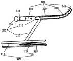
- Fig. 1is a schematic structural diagram of an anchoring device according to an embodiment of the present invention.
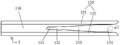
- Fig. 2is a structural schematic diagram of the proximal anchor of the anchoring device according to an embodiment of the present invention in one direction;
- Fig. 3is a structural schematic diagram of the proximal anchor of the anchoring device shown in Fig. 2 in another direction;
- FIG. 4is a schematic diagram of the anchoring device according to an embodiment of the present invention when the connecting piece is clamped into the second anchoring portion of the proximal anchoring piece;
- Figure 5is a schematic diagram of the anchoring device provided by the present invention according to an embodiment of the present invention when the connector is clamped into the clamping section;
- Fig. 6is a schematic diagram of the anchoring device provided by the present invention according to an embodiment when the connector is locked into the buffer section;
- Fig. 7is a schematic cross-sectional view perpendicular to the X direction of the proximal anchor in the anchoring device according to an embodiment of the present invention
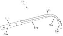
- Fig. 8is a schematic structural diagram of a distal end anchoring member in the anchoring device according to an embodiment of the present invention.
- Fig. 9is a schematic diagram of the connection relationship between the connector and the distal anchoring element in the anchoring device according to an embodiment of the present invention.
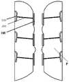
- Figure 10is a schematic diagram of implanting multiple anchoring devices provided by embodiments of the present invention in a patient
- FIG. 11a to 11gare schematic diagrams of the process of implanting the anchoring device provided by the embodiment of the present invention into the tissue;
- Fig. 12is a schematic diagram of the distal end of the connector of the anchoring device provided by an embodiment of the present invention being formed as a tip;
- FIG. 13is a schematic structural diagram of an auxiliary tool for assembling a connector and a distal end anchor according to an embodiment of the present invention, and the heating wire is not shown in the figure;
- FIG. 14is a cross-sectional view of the working part of the auxiliary tool for assembling the connector and the distal end anchor according to an embodiment of the present invention
- 15is a schematic diagram of an auxiliary tool for assembling a connector and a distal end anchor according to an embodiment of the present invention when the crimping and hot-melting processes are performed at the same time;
- 16is a schematic diagram of the force applied to the anchoring device when the connecting piece and the distal end anchoring piece are assembled by using the crimping auxiliary tool according to an embodiment of the present invention.
- the singular forms “a”, “an” and “the”include plural objects, and the plural form “plurality” includes two or more objects, unless the content clearly indicates otherwise.
- the term “or”is usually used to include the meaning of “and/or”, unless the content clearly indicates otherwise, and the terms “installed”, “connected”, and “connected” shall be used. In a broad sense, for example, it can be a fixed connection, a detachable connection, or an integral connection. It can be a mechanical connection or an electrical connection. It can be directly connected, or indirectly connected through an intermediate medium, and it can be a communication between two elements or an interaction relationship between two elements.
- the specific meanings of the above-mentioned terms in the present inventioncan be understood according to specific situations.
- the same or similar reference signs in the drawingsrepresent the same or similar components.
- proximal end and distal endrefer to the relative orientation, relative position, and direction of elements or actions relative to each other from the perspective of the doctor using the medical device, although “proximal end” and “distal end” Not restrictive, but “proximal” usually refers to the end of the medical device that is close to the doctor during normal operation, and “distal” usually refers to the end that first enters the patient's body.
- the embodiments of the present inventionprovide an anchor and an anchor device, which can be used to implant prostate tissue to treat benign prostatic hyperplasia, or implant other anatomical structures to treat other diseases.
- this embodimentis introduced by taking the use of the anchoring device to treat benign prostatic hyperplasia as an example.
- the anchorwhen the anchor is applied to the anchoring device, the anchor is defined as a proximal anchor, so “proximal anchor” is used to refer to the hereinafter. Anchor.
- the anchoring deviceincludes a proximal anchor 100, a connecting piece 200, and a distal anchor 300, wherein the connecting piece 200 includes a first connecting portion 210 and a second connecting portion.
- the first connecting part 210is fixedly connected to the distal anchor 300, and the second connecting part 220 is selectively connected to the proximal anchor 100.
- the proximal anchor 100includes a first anchor portion 110 and a second anchor portion 120 extending from one end of the first anchor portion 110.
- the second anchoring portion 120includes a first anchoring piece 121 and a second anchoring piece 122 arranged at intervals, and a clamping groove is formed between the first anchoring piece 121 and the second anchoring piece 122.
- the clamping grooveincludes a buffer section 131, a clamping section 132 and a first transition section 133.
- the width of the clamping section 132is greater than the width of the buffer section 131, the width of the first transition section 133 gradually increases in a direction away from the clamping section 132, and the first transition section 133 The minimum width of is smaller than the width of the clamping section 132.
- the “width” hereinrefers to the separation distance between the first anchor piece 121 and the second anchor piece 122. Taking the illustrated direction as an example, the proximal anchor 100 extends along the X direction, and the Y direction may be the width direction of the proximal anchor 100.
- the clamping groove of the second anchoring portion 120is used to clamp the proximal end of the second connecting portion 220 (that is, the second connecting portion 220 is away from the first connecting portion 210). This end is also the proximal end of the connecting member 200.
- the end of the first connecting portion 210 away from the second connecting portion 220will be referred to as the distal end of the second connecting portion 220 hereinafter Or the distal end of the connecting piece 200) to realize the connection between the proximal anchor 100 and the connecting piece 200.
- the axial direction of the second connecting portion 220is perpendicular to the X direction and the Y direction.
- a force F1is applied to the second connecting portion 220, so that the second connecting portion 220 can enter the clamping groove from the first transition section 133, and be blocked by the second connecting portion 132 at the clamping section 132.
- the two anchoring parts 120are clamped to realize the connection between the proximal anchor 100 and the connecting member 200, as shown in FIG. 5.
- the clamping grooveis provided with the buffer section 131.
- the buffer section 131can play a buffering role to prevent the first anchoring piece 121 and the second anchoring piece 122 from being affected by
- the force F2 ofis too large to cause deformation of the first anchoring piece 121 and the second anchoring piece 122.
- the width of the clamping section 132is greater than the width of the buffer section 131, so when the second connecting portion 220 is displaced by force and at least partially enters the buffer section 131 (as shown in FIG. 6), The second connecting portion 220 can also return to the clamping section 132.
- the minimum width of the first transition section 133is smaller than the width of the clamping section 132, which is equivalent to forming a convex limit structure at the intersection of the clamping section 132 and the first transition section 133. In this way, the second connecting portion 220 clamped by the clamping section 132 is difficult to slide to the first transition section 133, which causes the proximal anchor 100 and the connecting member 200 to separate.
- the radial cross section of the proximal end of the second connecting portion 220is circular, the length of the buffer section 131 is greater than the diameter of the radial cross section of the proximal end of the second connecting portion 220, and the first The minimum width of a transition section 133 is smaller than the diameter of the radial cross section of the proximal end of the second connecting portion 220, and the maximum width of the first transition section 133 is greater than the radial diameter of the proximal end of the second connecting portion 220 The diameter of the section.
- the "length"refers to the size of each part of the proximal anchor 100 in the X direction.
- the clamping groovefurther includes an opening section 134 disposed at an end of the first transition section 133 away from the clamping section 132, and The width of the opening section 134 is equal to the maximum width of the first transition section 133.
- the first anchoring piece 121 and the second anchoring piece 122have a certain thickness at the opening section 134, so as to avoid damage to the prostate when the anchoring device is implanted into the patient’s prostate. The tissue causes unnecessary damage.
- the "thickness"refers to the size of the first anchor sheet 121 or the second anchor sheet 122 in the Y direction.
- first anchoring portion 110should also have a predetermined length to ensure the strength of the proximal anchor 100.
- the length of the first anchor portion 110accounts for 1/3-1/2 of the length of the proximal anchor 100.
- the cross-sectional shape of the proximal anchor 100 perpendicular to the X directioncan be circular, elliptical, drop-shaped, waist-shaped, etc., but preferably the cross-sectional shape is waist-shaped, and the length of the waist-shaped Extending in the Y direction (as shown in Figures 2 and 7), the advantage of this arrangement is that when the anchoring device is implanted into the patient’s prostate tissue, the proximal anchor 100 has greater contact with the prostate tissue Area can improve anchoring performance.
- the distal anchor 300includes an anchor body and a bending structure extending from one end of the anchor body, and the anchor body includes a third anchor having a tubular shape.
- a fixing portion 310, the third anchoring portion 310is used to connect with the connecting member 200.
- the first connecting portion 210is disposed in the lumen of the third anchoring portion 310, and the first connecting portion 210 and the third anchoring portion 310 are fixed by crimping, so that the The tube wall of the third anchoring portion 310 extends into the lumen to form a limiting recess 311, while the first connecting portion 210 is formed with a fixing groove that matches the limiting recess 311 (in the figure) Not marked).
- the limiting recessed portion 311protrudes from the inner wall of the lumen and is matched with the fixing groove, thereby preventing the connecting member 200 from being along
- the axial movement of the lumen of the third anchor portion 310 and the rotation relative to the third anchor portion 310improve the stability of the connection between the distal end anchor 300 and the connector 200, thereby improving The reliability of the anchoring device.
- the limiting recessed portion 311is recessed inward, which can be used to load drugs to improve the treatment effect of benign prostatic hyperplasia.
- the length of the third anchor portion 310accounts for 1/10-1/2 of the length of the anchor body.
- the shape of the cross section of the limiting recess 311 in the extending direction of the lumen of the third anchoring portion 310is semicircular.
- the limiting recess The shape of the cross section of 311 in the direction in which the third anchoring portion 310 extends in the lumenmay also be U-shaped, V-shaped, or the like.
- the distal end of the connecting member 200(that is, the end of the first connecting portion 210 away from the second connecting portion 220) is also provided with a limiting portion 230, the diameter of the limiting portion 230 Is larger than the inner diameter of the lumen of the third anchoring portion 310 and located outside the lumen of the third anchoring portion 310 to restrict the first connecting portion 210 from the third anchoring portion 310 Sliding out of the lumen. Since the restricting portion 230 is used to restrict the first connecting portion 210 from sliding out of the lumen of the third anchoring portion 310, it can restrict the connecting member 200 along the tube of the third anchoring portion 310.
- the axial movement of the cavityfurther improves the connection stability of the distal end anchor 300 and the connector 200, and improves the anchoring reliability of the anchoring device.
- the assembling method of the connecting member 200 and the distal end anchoring member 300, and the forming method of the limiting portion 230will be described in detail later.
- the anchor bodyfurther includes a fourth anchor portion 320
- the fourth anchor portion 320is a curved sheet structure, and is used to connect the third anchor portion 310 and the bending structure.
- the fourth anchoring portion 320wraps at least 1/2 of the circumferential surface in the circumferential direction of the anchoring body to Ensure the strength of the joint between the third anchor portion 310 and the fourth anchor portion 320 to avoid breakage during use. Further, along the direction away from the third anchoring portion 310, the circumferential surface covered by the fourth anchoring portion 320 on the circumference of the anchoring body gradually decreases to reduce stress concentration and stress strain .
- the bending structureis a curved sheet structure and includes a bending portion 330, the fourth anchoring portion 320 is close to the bending portion 330, the fourth anchoring A notch 321 is formed on the side of the fixed portion 320.
- the notch 321may be formed by an inclined surface, but those skilled in the art will know that the notch may also be formed by an arc surface, a stepped surface, or other curved or straight surfaces.
- the fourth anchoring portion 320wraps at least 1/12 of the circumferential surface in the circumferential direction of the anchoring body.
- the bending structurefurther includes a fifth anchoring portion 340.
- the length of the fifth anchoring portion 340is 0.5mm-1mm, and the fifth anchoring portion 340
- the angle formed between the anchor portion 340 and the axis of the anchor bodyis greater than or equal to 90° and less than 180°.
- the circumferential surface covered by the fifth anchoring portion 340is larger than the circumferential surface covered by the bending portion 330.
- the fifth anchoring portion 340covers at least 1/2 of the circumferential surface, and the bent portion 330 may only cover about 1/12 of the circumferential surface.
- the bending structurefurther includes a second transition section (not marked in the figure), and the second transition section is used to connect the bending portion 330 and the fifth anchoring portion 340 .
- the various components of the distal end anchor 300are smoothly connected so that no sharp corners appear on the distal end anchor 300, so as to reduce stress concentration.
- the connecting piece 200 and the distal anchoring piece 300have been assembled and molded before being implanted in the patient's body, and the connecting piece 200 and the proximal anchoring piece 100 Connect after implantation in the patient.
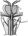
- 10is a schematic diagram of implanting the anchoring device provided by an embodiment of the present invention on the prostate P of a patient, wherein the distal anchor 300 is positioned on the distal tissue of the prostate P, and the proximal anchor 100 Is positioned on the proximal tissue of the prostate P, and the anchor body of the distal anchor 300 and the proximal anchor 100 are approximately parallel, so the connector 200 is L-shaped (combined with FIG. 9 Show).
- a sheath tube 10is advanced through the urethra, so that the distal end of the sheath tube 10 is placed near the area where the urethra is obstructed by hypertrophic prostate tissue; and the distal end anchoring delivery device 20 is introduced through the sheath tube 10, the distal end The distal end of the anchoring delivery device 20 penetrates from the distal end of the sheath tube 10.
- the distal anchored delivery device 20can be put into the sheath 10, or the sheath 10 can be placed before the urethra
- the distal anchoring delivery deviceis pre-loaded into the sheath 10. The situation after the distal end of the distal end anchoring delivery device 20 passes through the distal end of the sheath tube 10 is shown in FIG. 11a.
- the puncture needle 30is introduced through the distal end anchored delivery device 20, and the puncture needle 30 passes through the distal end anchored delivery device 20, and reaches from the distal opening of the distal end anchored delivery device 20.
- the puncture needle 30further advances, and the puncture needle 30 pierces the prostate tissue and out of the prostate capsule, as shown in Fig. 11b.
- the distal end anchor 300passes through the distal end of the puncture needle 30, as shown in Fig. 11c.
- the puncture needle 30is recovered, so that the puncture needle 30 is removed from the distal end anchoring delivery device 20, and the distal end anchor 300 is released at the same time, as shown in FIG. 11d.
- the proximal anchored delivery device 40is introduced through the sheath 10, and the distal end of the proximal anchored delivery device 40 penetrates the distal end of the sheath 10.
- the connector 200can be passed through the proximal anchor located in the proximal anchored delivery device At this time, the connecting piece 200 and the proximal anchoring piece 100 are still in a separated state, and the position of the connecting piece 200 relative to the proximal anchoring piece 100 can be adjusted in real time, as shown in Fig. 11f .
- the proximal anchor 100is connected to the connecting member 200 so that the position of the proximal anchor 100 is relatively fixed, and the proximal anchor 100 is anchored from the proximal end The delivery device 40 is released.
- the proximal anchor 100is placed in the tissue, so that an anchoring device is implanted in the tissue, as shown in FIG. 11g.
- FIGS. 13 and 14show schematic diagrams of an auxiliary tool 1000 for assembling the distal end anchor 300 and the connecting member 200.
- the auxiliary tooling 1000includes a fixture 1100 and a working part 1200.
- the fixture 1100includes two symmetrically arranged sub fixtures 1110.
- Each of the sub fixtures 1110includes a base 1111 and a slave.
- the clamping arms 1112 extending from the base 1111are provided with recessed clamping areas on the opposite surfaces of the two clamping arms 1112.
- the two sub-fixtures 1110are spliced with each other to form the clamp At 1100, the two clamping areas are aligned and can be used to clamp the distal anchor 300.
- the working part 1200includes a crimping section 1210 and a heating section 1220 arranged along its axial direction.
- the crimping section 1210is provided with a working cavity extending along its axial direction, and the working cavity has an opening, and the third anchoring portion 310 of the distal end anchor 300 can pass from the opening. Insert the working cavity.
- the surface of the bottom of the working cavity(the end of the working cavity opposite to the opening) is a part of a spherical surface, such as a 1/2 spherical surface, and preferably the bottom of the working cavity partially extends to the heating section 1220.
- the distal end anchor 300 and the connecting member 200are fixed by crimping, the connecting member 200 is a rod-shaped structure, and the limiting portion 230 is formed by hot melting.
- the assembling process of the connecting piece 200 and the distal anchoring piece 300includes the following steps:
- the distal end of the connector 200is inserted into the lumen of the third anchoring portion 310 from one end of the third anchoring portion 310 (the end connected to the fourth anchoring portion 320) , And then pass through the other end of the lumen.
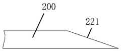
- the distal end of the connector 200is processed into a tip 221, as shown in FIG. 12.
- the length of the tip 221is about 1 mm, and the length of the part of the connecting member 200 that passes through the lumen is 3-4 mm.
- the two sub-clamps 1110are respectively connected with pneumatic parts (not shown in the figure), and the pneumatic parts provide pressure to the sub-clamps 1110, so that the two sub-clamps 1110 clamp the distal end.
- Anchor 300inserts the third anchor portion 310 of the distal end anchor 300 into the working cavity of the working portion 1200, and the distal end of the connecting piece 200 is located at the bottom of the working cavity. It is understandable that the order of these two steps can also be interchanged in actual operation.
- a heating wire 2000is provided on the outer surface of the heating section 1220 of the working part 1200, and electric energy is provided to the heating wire 2000 so that the heating wire 2000 generates heat, and then the distal end of the connecting member 200 is heated. melt.
- a crimping device(not shown in the figure) is used to apply a force F3 to the crimping section 1210 in the circumferential direction of the crimping section 1210 to make the third anchoring of the distal end anchor 300
- the portion 310is crimped and fixed to the connecting member 200. During this process, the force applied to the distal end anchoring member 300 and the connecting member 200 is shown in FIGS. 15 and 16.
- the heatingis stopped, and after the working part 1200 is cooled, the limiting part 230 is formed at the distal end of the connecting member 200.
- the simultaneous execution of the crimping process and the hot-melt processis taken as an example.
- the crimping process and the hot-melt processcan also be performed step by step. You can either perform the crimping process first and then perform the hot-melt process, or The hot melt process is performed first and then the crimping process, which is not limited in the present invention.
- the connecting member 200may also be a rope structure.
- the limiting portion 230may be formed by knotting.
Landscapes
- Health & Medical Sciences (AREA)
- Life Sciences & Earth Sciences (AREA)
- Engineering & Computer Science (AREA)
- Biomedical Technology (AREA)
- Surgery (AREA)
- General Health & Medical Sciences (AREA)
- Veterinary Medicine (AREA)
- Heart & Thoracic Surgery (AREA)
- Public Health (AREA)
- Animal Behavior & Ethology (AREA)
- Nuclear Medicine, Radiotherapy & Molecular Imaging (AREA)
- Medical Informatics (AREA)
- Molecular Biology (AREA)
- Oral & Maxillofacial Surgery (AREA)
- Transplantation (AREA)
- Vascular Medicine (AREA)
- Pathology (AREA)
- Cardiology (AREA)
- Rheumatology (AREA)
- Prostheses (AREA)
- Surgical Instruments (AREA)
Abstract
Description
Translated fromChinese本发明涉及医疗器械技术领域,具体涉及一种锚定件和锚定装置。The invention relates to the technical field of medical devices, in particular to an anchoring piece and an anchoring device.
良性前列腺增生是引起中老年男性排尿障碍问题中最为常见的一种良性疾病,其主要表现为组织学上的前列腺间质和腺体成分的增生、解剖学上的前列腺增大、下尿路症状为主的临床症状以及尿动力学上的膀胱出口梗阻。Benign prostatic hyperplasia is the most common benign disease that causes urinary dysfunction in middle-aged and elderly men. It is mainly manifested as histological prostatic interstitial and glandular hyperplasia, anatomical prostate enlargement, and lower urinary tract symptoms The main clinical symptoms and urodynamic bladder outlet obstruction.
除药物治疗外,良性前列腺增生的手术方式有以下几种:(1)经尿道前列腺电切术;(2)耻骨上或耻骨后前列腺切除术;(3)激光前列腺剜除术或切除术;(4)前列腺支架在内的微创伤治疗。In addition to drug treatment, there are several surgical methods for benign prostatic hyperplasia: (1) transurethral resection of the prostate; (2) suprapubic or retropubic prostatectomy; (3) laser enucleation or resection of the prostate; (4) Minimally traumatic treatment including prostate stent.
前列腺支架在内的微创伤治疗中通常采用一种锚定装置,这种锚定装置是一种用于缓解尿流细小的永久性植入物。这种锚定装置通过输送系统植入尿道中,植入后机械性地将前列腺左右两叶分开,以将压迫尿道的前列腺组织推开,从而起到治疗的效果。这种锚定装置的侵袭性极低,且无需进行消融,可以持续缓解患者的症状,治疗效果较好。An anchoring device is usually used in minimally invasive treatments including prostate stents. This anchoring device is a small permanent implant used to relieve the flow of urine. This anchoring device is implanted into the urethra through a delivery system, and after implantation, the left and right lobes of the prostate are mechanically separated to push away the prostate tissue that presses the urethra, thereby achieving a therapeutic effect. The anchoring device has extremely low invasiveness, does not require ablation, can continuously relieve the patient's symptoms, and has a good therapeutic effect.
目前,锚定装置通常包括远端锚定件、近端锚定件以及连接件,所述连接件分别与所述远端锚定件和所述近端锚定件连接。这种锚定装置植入后存在移位的风险,治疗的有效性和稳定性等需提高。At present, an anchoring device usually includes a distal anchoring piece, a proximal anchoring piece, and a connecting piece, and the connecting piece is connected to the distal anchoring piece and the proximal anchoring piece, respectively. This kind of anchoring device has the risk of displacement after implantation, and the effectiveness and stability of the treatment need to be improved.
发明内容Summary of the invention
本发明的目的在于提供一种锚定件和锚定装置,以解决现有的锚定件和锚定装置植入后容易移位的问题。The purpose of the present invention is to provide an anchoring piece and an anchoring device to solve the problem of easy displacement of the existing anchoring piece and anchoring device after implantation.
为实现上述目的,本发明提供的锚定件,包括第一锚定部和从所述第一锚定部的一端延伸的第二锚定部;To achieve the above objective, the anchor provided by the present invention includes a first anchor portion and a second anchor portion extending from one end of the first anchor portion;
所述第二锚定部包括间隔设置的第一锚定片和第二锚定片,所述第一锚定片和所述第二锚定片之间形成夹持槽;沿所述第一锚定部到所述第二锚定部的方向,所述夹持槽包括依次设置的缓冲段、夹持段和第一过渡段,所述 夹持段的宽度大于所述缓冲段的宽度,所述第一过渡段的宽度沿远离所述夹持段的方向逐渐增大,且所述第一过渡段的最小宽度小于所述夹持段的宽度;其中,所述宽度是指所述第一锚定片与所述第二锚定片之间的间隔距离。The second anchoring portion includes a first anchoring piece and a second anchoring piece arranged at intervals, and a clamping groove is formed between the first anchoring piece and the second anchoring piece; From the anchoring part to the second anchoring part, the clamping groove includes a buffer section, a clamping section and a first transition section arranged in sequence, the width of the clamping section is greater than the width of the buffer section, The width of the first transition section gradually increases in a direction away from the clamping section, and the minimum width of the first transition section is smaller than the width of the clamping section; wherein, the width refers to the first The separation distance between an anchor piece and the second anchor piece.
可选地,所述夹持槽用于夹持一目标物,所述缓冲段的长度大于所述目标物之径向截面的直径。Optionally, the clamping groove is used to clamp a target, and the length of the buffer section is greater than the diameter of the radial cross-section of the target.
可选地,所述第一过渡段的最小宽度小于所述目标物之径向截面的直径,且所述第一过渡段的最大宽度大于所述目标物之径向截面的直径。Optionally, the minimum width of the first transition section is smaller than the diameter of the radial section of the target, and the maximum width of the first transition section is larger than the diameter of the radial section of the target.
可选地,在所述锚定件的延伸方向上,所述第一锚定部的长度与所述锚定件的长度的比值范围为[1/10,1/2]。Optionally, in the extension direction of the anchor, the ratio of the length of the first anchor portion to the length of the anchor is in the range of [1/10, 1/2].
可选地,所述夹持槽还包括开口段,所述开口段设置于所述第一过渡段远离所述夹持段的一端,且所述开口段的宽度等于所述第一过渡段的最大宽度。Optionally, the clamping groove further includes an opening section disposed at an end of the first transition section away from the clamping section, and the width of the opening section is equal to that of the first transition section. Maximum width.
为实现上述目的,本发明还提供了一种锚定装置,包括连接件、远端锚定件和如前任一项所述的锚定件,所述连接件包括第一连接部和第二连接部,所述远端锚定件与所述第一连接部固定连接,所述锚定件的所述第二锚定部用于夹持所述第二连接部而使所述锚定件与所述第二连接部连接。In order to achieve the above objective, the present invention also provides an anchoring device, comprising a connector, a distal end anchor and the anchor as described in any one of the preceding, the connector includes a first connecting part and a second connecting part Part, the distal end anchor is fixedly connected to the first connecting part, and the second anchor part of the anchor is used to clamp the second connecting part to make the anchor and The second connecting part is connected.
可选地,所述远端锚定件包括锚定主体和从所述锚定主体的一端延伸出的弯折结构,所述锚定主体包括呈管状的第三锚定部;Optionally, the distal end anchor includes an anchor main body and a bending structure extending from one end of the anchor main body, and the anchor main body includes a third anchor portion having a tubular shape;
所述第一连接部设置于所述第三锚定部的管腔中,且所述第一连接部与所述第三锚定部通过压接固定,以使所述第三锚定部的管壁向管腔内延伸而形成限位凹陷部,同时所述第一连接部上形成与所述限位凹陷部相匹配的固定凹槽。The first connecting portion is arranged in the lumen of the third anchoring portion, and the first connecting portion and the third anchoring portion are fixed by crimping, so that the third anchoring portion The tube wall extends into the lumen to form a limiting recess, and at the same time, a fixing groove matching the limiting recess is formed on the first connecting part.
可选地,所述第一连接部远离所述第二连接部的一端设有限位部,所述限位部的直径大于所述管腔的内径,且所述限位部位于所述第三锚定部的管腔外部,以用于限制所述第一连接部从所述第三锚定部的管腔中滑出。Optionally, an end of the first connecting portion away from the second connecting portion is provided with a limiting portion, the diameter of the limiting portion is larger than the inner diameter of the lumen, and the limiting portion is located at the third The outside of the lumen of the anchoring portion is used to restrict the first connecting portion from sliding out of the lumen of the third anchoring portion.
可选地,所述锚定主体还包括第四锚定部,所述第四锚定部为曲面片状结构,并用于连接所述第三锚定部和所述弯折结构;在所述第四锚定部与所述第三锚定部相接处,所述第四锚定部在所述锚定主体的周向上包覆至少1/2 的圆周面。Optionally, the anchoring body further includes a fourth anchoring portion, the fourth anchoring portion is a curved sheet structure, and is used to connect the third anchoring portion and the bending structure; Where the fourth anchoring portion and the third anchoring portion are connected, the fourth anchoring portion wraps at least 1/2 of the circumferential surface in the circumferential direction of the anchoring body.
可选地,沿远离所述第三锚定部的方向,所述第四锚定部在所述锚定主体的周向上包覆的圆周面逐渐减小。Optionally, in a direction away from the third anchoring portion, the circumferential surface of the fourth anchoring portion wrapped in the circumferential direction of the anchoring body gradually decreases.
可选地,所述弯折结构包括弯折部;在所述弯折部与所述第四锚定部相接处,所述第四锚定部在所述锚定主体的周向上包覆至少1/12的圆周面。Optionally, the bending structure includes a bending portion; where the bending portion and the fourth anchoring portion meet, the fourth anchoring portion wraps around the anchor body At least 1/12 of the circumference.
可选地,所述弯折结构还包括第五锚定部,所述第五锚定部设置于所述弯折部远离所述第四锚定部的一端;所述第五锚定部与所述锚定主体的轴线之间所形成的夹角的角度范围为[90°,180°)。Optionally, the bending structure further includes a fifth anchoring portion provided at an end of the bending portion away from the fourth anchoring portion; the fifth anchoring portion is connected to The angle range of the included angle formed between the axes of the anchoring main body is [90°, 180°).
可选地,所述弯折结构为曲面片状结构,在所述弯折结构的圆周上,所述第五锚定部包覆至少1/2的圆周面。Optionally, the bending structure is a curved sheet structure, and on the circumference of the bending structure, the fifth anchor portion covers at least 1/2 of the circumferential surface.
可选地,在所述弯折结构的轴向上,所述第五锚定部的长度为0.5mm-1mm。Optionally, in the axial direction of the bending structure, the length of the fifth anchoring portion is 0.5 mm-1 mm.
可选地,在所述锚定主体的轴向上,所述第三锚定部的长度与所述锚定主体的长度的比值范围为[1/10,1/2]。Optionally, in the axial direction of the anchor body, the ratio of the length of the third anchor portion to the length of the anchor body is in the range of [1/10, 1/2].
与现有技术相比,本发明的锚定件和锚定装置具有如下优点:Compared with the prior art, the anchor and the anchor device of the present invention have the following advantages:
前述的锚定件包括第一锚定部和从所述第一锚定部的一端延伸的第二锚定部,所述第二锚定部包括间隔设置的第一锚定片和第二锚定片,所述第一锚定片和所述第二锚定片之间形成夹持槽;沿所述第一锚定部到所述第二锚定部的方向,所述夹持槽包括依次设置的缓冲段、夹持段和第一过渡段,所述夹持段的宽度大于所述缓冲段的宽度,所述第一过渡段的宽度沿远离所述夹持段的方向逐渐增大,且所述第一过渡段的最小宽度小于所述夹持段的宽度,所述宽度是指所述第一锚定片和所述第二锚定片之间的间隔距离。将所述锚定件应用于所述锚定装置上时,其作为近端锚定件使用,所述锚定装置还包括连接件,所述第二锚定部用于夹持所述连接件,以使所述连接件与所述锚定件连接,所述缓冲段一方面用于在将所述连接件卡入所述夹持段的过程中,避免所述第一过渡段的分叉变形,另一方面在将所述锚定装置植入患者体内后,连接件可以至少部分被缓冲段夹持,这样当所述锚定装置的部分部件发生移位时,所述连接件可滑移至所述夹持段,从而使得所述连接件与 所述锚定件仍保持连接,提高所述锚定装置的使用可靠性。The aforementioned anchor includes a first anchor portion and a second anchor portion extending from one end of the first anchor portion, and the second anchor portion includes a first anchor piece and a second anchor that are arranged at intervals A fixing piece, a clamping groove is formed between the first anchoring piece and the second anchoring piece; along the direction from the first anchoring portion to the second anchoring portion, the clamping groove includes A buffer section, a clamping section and a first transition section are arranged in sequence, the width of the clamping section is greater than the width of the buffer section, and the width of the first transition section gradually increases in a direction away from the clamping section , And the minimum width of the first transition section is smaller than the width of the clamping section, and the width refers to the separation distance between the first anchor piece and the second anchor piece. When the anchoring piece is applied to the anchoring device, it is used as a proximal anchoring piece, the anchoring device further includes a connecting piece, and the second anchoring portion is used to clamp the connecting piece , So that the connecting piece is connected with the anchoring piece, on the one hand, the buffer section is used to avoid the bifurcation of the first transition section when the connecting piece is clamped into the clamping section Deformation. On the other hand, after the anchoring device is implanted in the patient, the connector can be at least partially clamped by the buffer section, so that when part of the anchoring device is displaced, the connector can slide Move to the clamping section, so that the connecting piece and the anchoring piece are still connected, and the reliability of the anchoring device is improved.
图1是本发明根据一实施例所提供的锚定装置的结构示意图;Fig. 1 is a schematic structural diagram of an anchoring device according to an embodiment of the present invention;
图2是本发明根据一实施例所提供的锚定装置的近端锚定件在一个方向上的结构示意图;Fig. 2 is a structural schematic diagram of the proximal anchor of the anchoring device according to an embodiment of the present invention in one direction;
图3是图2所示的锚定装置的近端锚定件在另一个方向上的结构示意图;Fig. 3 is a structural schematic diagram of the proximal anchor of the anchoring device shown in Fig. 2 in another direction;
图4是本发明根据一实施例所提供的锚定装置中在将连接件卡入近端锚定件的第二锚定部时的示意图;4 is a schematic diagram of the anchoring device according to an embodiment of the present invention when the connecting piece is clamped into the second anchoring portion of the proximal anchoring piece;
图5是本发明根据一实施例所提供的锚定装置中连接件卡入夹持段时的示意图;Figure 5 is a schematic diagram of the anchoring device provided by the present invention according to an embodiment of the present invention when the connector is clamped into the clamping section;
图6是本发明根据一实施例所提供的锚定装置中连接件卡入缓冲段时的示意图;Fig. 6 is a schematic diagram of the anchoring device provided by the present invention according to an embodiment when the connector is locked into the buffer section;
图7是本发明根据一实施例所提供的锚定装置中近端锚定件的垂直于X方向的截面示意图;Fig. 7 is a schematic cross-sectional view perpendicular to the X direction of the proximal anchor in the anchoring device according to an embodiment of the present invention;
图8是本发明根据一实施例所提供的锚定装置中远端锚定件的结构示意图;Fig. 8 is a schematic structural diagram of a distal end anchoring member in the anchoring device according to an embodiment of the present invention;
图9是本发明根据一实施例所提供的锚定装置中连接件与远端锚定件的连接关系示意图;Fig. 9 is a schematic diagram of the connection relationship between the connector and the distal anchoring element in the anchoring device according to an embodiment of the present invention;
图10是在患者体内植入多个本发明实施例提供的锚定装置的示意图;Figure 10 is a schematic diagram of implanting multiple anchoring devices provided by embodiments of the present invention in a patient;
图11a至图11g是将本发明实施例提供的锚定装置植入组织内的过程示意图;11a to 11g are schematic diagrams of the process of implanting the anchoring device provided by the embodiment of the present invention into the tissue;
图12是本发明根据一实施例所提供的锚定装置之连接件的远端形成为尖端的示意图;Fig. 12 is a schematic diagram of the distal end of the connector of the anchoring device provided by an embodiment of the present invention being formed as a tip;
图13是本发明根据一实施例所提供的用于装配连接件和远端锚定件的辅助工装的结构示意图,图中未示出电热丝;FIG. 13 is a schematic structural diagram of an auxiliary tool for assembling a connector and a distal end anchor according to an embodiment of the present invention, and the heating wire is not shown in the figure;
图14是本发明根据一实施例所提供的用于装配连接件与远端锚定件的辅助工装的工作部的剖视图;14 is a cross-sectional view of the working part of the auxiliary tool for assembling the connector and the distal end anchor according to an embodiment of the present invention;
图15是本发明根据一实施例所提供的用于装配连接件与远端锚定件的辅助工装同时进行压接和热熔工艺时的示意图;15 is a schematic diagram of an auxiliary tool for assembling a connector and a distal end anchor according to an embodiment of the present invention when the crimping and hot-melting processes are performed at the same time;
图16是本发明根据一实施例所提供的利用压接辅助工装装配连接件与远端锚定件时,锚定装置的受力示意图。16 is a schematic diagram of the force applied to the anchoring device when the connecting piece and the distal end anchoring piece are assembled by using the crimping auxiliary tool according to an embodiment of the present invention.
[附图标记]:[Reference Signs]:
100-近端锚定件;100-Proximal anchor;
110-第一锚定部;110-The first anchoring part;
120-第二锚定部;120-The second anchoring part;
121-第一锚定片,122-第二锚定片;121-The first anchor piece, 122-The second anchor piece;
131-缓冲段,132-夹持段,133-第一过渡段,134-开口段;131-buffer section, 132-clamping section, 133-first transition section, 134-opening section;
200-连接件;200-connector;
210-第一连接部;210-The first connecting part;
220-第二连接部;220-The second connecting part;
221-尖端;221-tip;
230-限位部;230-limiting part;
300-远端锚定件;300-distal anchor;
310-第三锚定部;310-The third anchoring part;
311-限位凹陷部;311-Limiting recessed part;
320-第四锚定部;320-The fourth anchoring part;
321-缺口;321- gap;
330-弯折部;330-Bending part;
340-第五锚定部;340- The fifth anchoring part;
10-鞘管,20-远端锚定输送装置,30-穿刺针,40-近端锚定输送装置;10-sheath, 20-distal anchored delivery device, 30-puncture needle, 40-proximal anchored delivery device;
1000-辅助工装;1000- auxiliary tooling;
1100-夹具;1100-fixture;
1110-子夹具;1110-Sub-fixture;
1111-基座,1112-夹持臂;1111-base, 1112-clamping arm;
1200-工作部;1200-Work Department;
1210-压接段;1220-加热段;1210-crimping section; 1220-heating section;
2000-加热丝。2000- Heating wire.
为使本发明的目的、优点和特征更加清楚,以下结合附图对本发明作进一步详细说明。需说明的是,附图均采用非常简化的形式且均使用非精准的比例,仅用以方便、明晰地辅助说明本发明实施例的目的。In order to make the purpose, advantages and features of the present invention clearer, the present invention will be further described in detail below with reference to the accompanying drawings. It should be noted that the drawings all adopt a very simplified form and all use imprecise proportions, which are only used to conveniently and clearly assist in explaining the purpose of the embodiments of the present invention.
如在本说明书中所使用的,单数形式“一”、“一个”以及“该”包括复数对象,复数形式“多个”包括两个以上的对象,除非内容另外明确指出外。如在本说明书中所使用的,术语“或”通常是以包括“和/或”的含义而进行使用的,除非内容另外明确指出外,以及术语“安装”、“相连”、“连接”应做广义理解,例如,可以是固定连接,也可以是可拆卸连接,或一体地连接。可以是机械连接,也可以是电连接。可以是直接相连,也可以通过中间媒介间接相连,可以是两个元件内部的连通或两个元件的相互作用关系。对于本领域的普通技术人员而言,可以根据具体情况理解上述术语在本发明中的具体含义。附图中相同或相似的附图标记代表相同或相似的部件。As used in this specification, the singular forms "a", "an" and "the" include plural objects, and the plural form "plurality" includes two or more objects, unless the content clearly indicates otherwise. As used in this specification, the term "or" is usually used to include the meaning of "and/or", unless the content clearly indicates otherwise, and the terms "installed", "connected", and "connected" shall be used. In a broad sense, for example, it can be a fixed connection, a detachable connection, or an integral connection. It can be a mechanical connection or an electrical connection. It can be directly connected, or indirectly connected through an intermediate medium, and it can be a communication between two elements or an interaction relationship between two elements. For those of ordinary skill in the art, the specific meanings of the above-mentioned terms in the present invention can be understood according to specific situations. The same or similar reference signs in the drawings represent the same or similar components.
本文中,术语“近端”和“远端”是从使用该医疗器械的医生角度来看相对于彼此的元件或动作的相对方位、相对位置、方向,尽管“近端”和“远端”并非是限制性的,但是“近端”通常指该医疗设备在正常操作过程中靠近医生的一端,而“远端”通常是指首先进入患者体内的一端。Herein, the terms "proximal end" and "distal end" refer to the relative orientation, relative position, and direction of elements or actions relative to each other from the perspective of the doctor using the medical device, although "proximal end" and "distal end" Not restrictive, but "proximal" usually refers to the end of the medical device that is close to the doctor during normal operation, and "distal" usually refers to the end that first enters the patient's body.
本发明实施例提供了一种锚定件和锚定装置,所述锚定装置可用于植入前列腺组织以治疗良性前列腺增生,或者植入其他的解剖学结构中以治疗其他疾病。为便于理解,本实施例以利用所述锚定装置治疗良性前列腺增生为例进行介绍。另外,在将所述锚定件应用于所述锚定装置中时,所述锚定件被定义为近端锚定件,因此后文中一律以“近端锚定件”来指代所述锚定件。The embodiments of the present invention provide an anchor and an anchor device, which can be used to implant prostate tissue to treat benign prostatic hyperplasia, or implant other anatomical structures to treat other diseases. For ease of understanding, this embodiment is introduced by taking the use of the anchoring device to treat benign prostatic hyperplasia as an example. In addition, when the anchor is applied to the anchoring device, the anchor is defined as a proximal anchor, so “proximal anchor” is used to refer to the hereinafter. Anchor.
请参考图1并结合图9,所述锚定装置包括近端锚定件100、连接件200和远端锚定件300,其中,所述连接件200包括第一连接部210和第二连接部220,所述第一连接部210与所述远端锚定件300固定连接,所述第二连接部 220与所述近端锚定件100选择性地连接。Please refer to FIG. 1 in conjunction with FIG. 9, the anchoring device includes a
请参考图2及图3,所述近端锚定件100包括第一锚定部110和从所述第一锚定部110的一端延伸出的第二锚定部120。所述第二锚定部120包括间隔设置的第一锚定片121和第二锚定片122,所述第一锚定片121和所述第二锚定片122之间形成夹持槽。沿所述第一锚定部110到所述第二锚定部120的方向,所述夹持槽包括缓冲段131、夹持段132和第一过渡段133。其中,所述夹持段132的宽度大于所述缓冲段131的宽度,所述第一过渡段133的宽度沿远离所述夹持段132的方向逐渐增大,且所述第一过渡段133的最小宽度小于所述夹持段132的宽度。此处所述“宽度”是指所述第一锚定片121和所述第二锚定片122之间的间隔距离。以图示方向为例,所述近端锚定件100沿X方向延伸,则Y方向可为所述近端锚定件100的宽度方向。2 and 3, the
本实施例中,所述第二锚定部120的所述夹持槽用于夹持所述第二连接部220的近端(即所述第二连接部220远离所述第一连接部210的一端,该端也是所述连接件200的近端。相对应地,后文中将所述第一连接部210远离所述第二连接部220的一端称之为第二连接部220的远端或连接件200的远端),以实现所述近端锚定件100与所述连接件200的连接。请参考图4,装配所述连接件200和所述近端锚定件100时,所述第二连接部220的轴向与X方向及Y方向垂直。向所述第二连接部220施加作用力F1,使得所述第二连接部220可从所述第一过渡段133进入所述夹持槽,并在所述夹持段132处被所述第二锚定部120夹持以实现所述近端锚定件100与所述连接件200的连接,如图5所示。所述夹持槽上设置有所述缓冲段131,在装配所述近端锚定件100和所述连接件200时,所述第二连接部220在进入所述夹持段132(如图5所示)时,甚至进入缓冲段131(如图6所示),所述缓冲段131可起到缓冲作用,避免所述第一锚定片121和所述第二锚定片122因受到的力F2过大而导致所述第一锚定片121和所述第二锚定片122发生变形。所述夹持段132的宽度大于所述缓冲段131的宽度,因此当所述第二连接部220受力移位而至少部分地进入到所述缓冲段131时(如图6所示),所述第二连接部220还能够回到所述夹持段132。所述第一过渡段133的最小宽度小于所述 夹持段132的宽度,这相当于在所述夹持段132与所述第一过渡段133相交处形成了凸出的限位结构。如此,被所述夹持段132夹持的所述第二连接部220难以滑移至所述第一过渡段133而导致所述近端锚定件100与所述连接件200相分离。In this embodiment, the clamping groove of the
优选地,通常所述第二连接部220之近端的径向截面为圆形,所述缓冲段131的长度大于所述第二连接部220之近端的径向截面的直径,所述第一过渡段133的最小宽度小于所述第二连接部220之近端的径向截面的直径,且所述第一过渡段133的最大宽度大于所述第二连接部220之近端的径向截面的直径。可理解,在所述近端锚定件100中,所述“长度”是指所述近端锚定件100的各个部分在X方向上的尺寸。Preferably, usually the radial cross section of the proximal end of the second connecting
进一步地,请继续参考图2及图3,所述夹持槽还包括开口段134,所述开口段134设置于所述第一过渡段133远离所述夹持段132的一端,且所述开口段134的宽度等于所述第一过渡段133的最大宽度。一般地,所述第一锚定片121及所述第二锚定片122在所述开口段134处具有一定的厚度,以避免在将所述锚定装置植入患者的前列腺时,对前列腺组织造成不必要的损伤。所述“厚度”是指所述第一锚定片121或所述第二锚定片122在Y方向上的尺寸。Further, please continue to refer to FIGS. 2 and 3, the clamping groove further includes an
另外,所述第一锚定部110还应具有预定的长度,以确保所述近端锚定件100的强度。所述第一锚定部110的长度占所述近端锚定件100的长度的1/3-1/2。In addition, the
此外,所述近端锚定件100在垂直于X方向的截面形状可以是呈圆形、椭圆形、水滴形、腰形等,但优选该截面的形状为腰形,且腰形的长度沿Y方向延伸(如图2及图7所示),这样设置的好处在于,将所述锚定装置植入患者的前列腺组织时,所述近端锚定件100与前列腺组织具有较大的接触面积,可提高锚固性能。In addition, the cross-sectional shape of the
请继续参考图1并结合图8,所述远端锚定件300包括锚定主体和从所述锚定主体的一端延伸出的弯折结构,所述锚定主体包括呈管状的第三锚定部310,所述第三锚定部310用于与所述连接件200连接。Please continue to refer to FIG. 1 in conjunction with FIG. 8. The
具体地,所述第一连接部210设置于所述第三锚定部310的管腔中,且所述第一连接部210与所述第三锚定部310通过压接固定,以使所述第三锚定部310的管壁向管腔内延伸而形成限位凹陷部311,同时所述第一连接部210上形成与所述限位凹陷部311相匹配的固定凹槽(图中未标注)。在所述第三锚定部310的管腔中,所述限位凹陷部311凸出所述管腔之内壁并与所述固定凹槽相配合,由此可避免所述连接件200沿着所述第三锚定部310的管腔的轴向移动以及相对于所述第三锚定部310转动,提高所述远端锚定件300与所述连接件200连接的稳定性,进而提高锚定装置的使用可靠性。在所述第三锚定部310的外壁上,所述限位凹陷部311向内凹陷,其可用于加载药物,以提高良性前列腺增生的治疗效果。较佳地,在所述锚定主体的轴向上,所述第三锚定部310的长度占所述锚定主体的长度的1/10-1/2。Specifically, the first connecting
请参考图9,所述限位凹陷部311在所述第三锚定部310的管腔内的延伸方向上的截面的形状呈半圆形,在其他实施例中,所述限位凹陷部311在所述第三锚定部310的管腔内延伸的方向上的截面的形状还可以呈U型、V型等。Please refer to FIG. 9, the shape of the cross section of the limiting
请继续参考图9,所述连接件200的远端(即所述第一连接部210背离所述第二连接部220的一端)上还设置有限位部230,所述限位部230的直径大于所述第三锚定部310之管腔的内径并位于所述第三锚定部310的管腔外部,以用于限制所述第一连接部210从所述第三锚定部310的管腔中滑出。由于所述限位部230用于限制所述第一连接部210从所述第三锚定部310的管腔中滑出,因此可限制连接件200沿所述第三锚定部310的管腔的轴向移动,从而进一步提高所述远端锚定件300与所述连接件200的连接稳定性,提高锚定装置的锚定可靠性。所述连接件200和所述远端锚定件300的装配方法,以及所述限位部230的成形方法将在后文中详细介绍。Please continue to refer to FIG. 9, the distal end of the connecting member 200 (that is, the end of the first connecting
请继续参考图8,所述锚定主体还包括第四锚定部320,所述第四锚定部320为曲面片状结构,并用于连接所述第三锚定部310和所述弯折结构。在所述第四锚定部320与所述第三锚定部310相接处,所述第四锚定部320在所述锚定主体的周向上包覆至少1/2的圆周面,以确保所述第三锚定部310与所 述第四锚定部320相接处的强度,避免在使用过程中发生断裂。进一步地,沿远离所述第三锚定部310的方向,所述第四锚定部320在所述锚定主体的圆周上所包覆的圆周面逐渐减小,以减少应力集中和应力应变。Please continue to refer to FIG. 8, the anchor body further includes a
请继续参考图8,本实施例中,所述弯折结构为曲面片状结构并包括弯折部330,所述第四锚定部320靠近所述弯折部330处,所述第四锚定部320的侧边形成有缺口321,所述缺口321可由倾斜面构成,但本领域技术人员可知悉,该缺口还可以是弧形面、阶梯面或其他曲线或直线构成的面来形成。在所述第四锚定部320与所述弯折部330相接处,所述第四锚定部320在所述锚定主体的周向上包覆至少1/12的圆周面。通过在所述远端锚定件300上设置弯折结构可利于将所述远端锚定件300固定于前列腺组织内部,降低所述远端锚定件300移位的风险。Please continue to refer to FIG. 8, in this embodiment, the bending structure is a curved sheet structure and includes a bending
较佳地,所述弯折结构还包括第五锚定部340,在所述弯折结构的轴向上,所述第五锚定部340的长度为0.5mm-1mm,且所述第五锚定部340与所述锚定主体的轴线之间所形成的夹角的角度大于等于90°而小于180°。在所述弯折结构的周向上,所述第五锚定部340包覆的圆周面大于所述弯折部330所包覆的圆周面,在一些实施例中,所述第五锚定部340包覆至少1/2的圆周面,而所述弯折部330可仅包覆约1/12的圆周面。此外,在一些实施例中,所述弯折结构还包括第二过渡段(图中未标注),所述第二过渡段用于连接所述弯折部330和所述第五锚定部340。Preferably, the bending structure further includes a
较佳地,所述远端锚定件300的各个部件之间皆光滑连接而使所述远端锚定件300上不出现尖锐拐角,以减少应力集中。Preferably, the various components of the
本实施例所述的锚定装置中,所述连接件200与所述远端锚定件300在植入患者体内之前已装配成型,而所述连接件200和所述近端锚定件100在植入患者体内之后再连接。图10是将本发明实施例提供的锚定装置植入患者前列腺P上的示意图,其中所述远端锚定件300被定位于前列腺P的远端组织上,所述近端锚定件100被定位于前列腺P的近端组织上,且所述远端锚定件300的锚定主体和所述近端锚定件100大致平行,因而所述连接件200呈L型(结合图9所示)。In the anchoring device of this embodiment, the connecting
下面结合图11a至图11g介绍利用所述锚定装置治疗良性前列腺增生的具体过程。The following describes the specific process of using the anchoring device to treat benign prostatic hyperplasia with reference to Figs. 11a to 11g.
首先,一鞘管10前进穿过尿道,从而使鞘管10的远端放置在尿道被肥大的前列腺组织阻碍的区域附近;并通过鞘管10引入远端锚定输送装置20,所述远端锚定输送装置20的远端从所述鞘管10的远端穿出。其中,可在鞘管10被放置在尿道中被阻碍的区域附近之后,再将所述远端锚定输送装置20放入鞘管10中,或者,可在将鞘管10植入尿道之前将所述远端锚定传送装置预先加载到所述鞘管10中。所述远端锚定输送装置20的远端从所述鞘管10的远端穿出后的情况如图11a所示。First, a
接着,通过所述远端锚定输送装置20引入穿刺针30,所述穿刺针30通过所述远端锚定输送装置20,并从所述远端锚定输送装置20的远端开口到达所述鞘管10的外部。所述穿刺针30进一步前进,所述穿刺针30刺穿前列腺组织并从前列腺囊中穿出,如图11b所示。Then, the
接着,所述远端锚定件300穿过所述穿刺针30的远端,如图11c所示。Next, the
接着,回收所述穿刺针30,使得所述穿刺针30从所述远端锚定输送装置20中移除,同时释放所述远端锚定件300,如图11d所示。Then, the
接着,从所述鞘管10中移除所述远端锚定输送装置20,并调整所述远端锚定件300的位置,如图11e所示。Next, remove the distal
接着,通过鞘管10引入近端锚定输送装置40,所述近端锚定输送装置40的远端从所述鞘管10的远端穿出。在所述近端锚定输送装置40的远端从所述鞘管10的远端穿出之前,可使所述连接件200穿过位于所述近端锚定输送装置中的近端锚定件100,此时所述连接件200与所述近端锚定件100仍处于分离状态,所述连接件200相对于所述近端锚定件100的位置可实时调整,如图11f所示。Next, the proximal
接着,通过所述连接件200拉动所述远端锚定件300,以调整所述远端锚定件300和所述近端锚定件100之间的相对位置,从而使肥大的前列腺组织收缩。之后,使所述近端锚定件100与所述连接件200连接以使所述近端锚定件100的位置相对固定,并使所述近端锚定件100从所述近端锚定输送装 置40中释放。由此,将所述近端锚定件100安置于组织中,从而将一个锚定装置植入组织,如图11g所示。Then, pull the
之后,根据实际情况,重复上述操作将其他的锚定装置植入前列腺组织,通常需要植入4-6个锚定装置,这些锚定装置共同作用以治疗良性前列腺增生。After that, according to the actual situation, repeat the above operation to implant other anchoring devices into the prostate tissue, usually 4-6 anchoring devices need to be implanted, and these anchoring devices work together to treat benign prostatic hyperplasia.
下面,本实施例将结合附图14-16介绍所述远端锚定件300与所述连接件200的连接方法。Hereinafter, this embodiment will introduce the method of connecting the
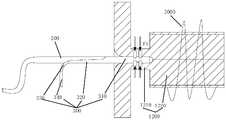
图13及图14示出了一种用于装配所述远端锚定件300和所述连接件200的辅助工装1000的示意图。如图13及图14所示,所述辅助工装1000包括夹具1100和工作部1200,所述夹具1100包括两个对称设置的子夹具1110,每个所述子夹具1110皆包括基座1111和从所述基座1111上延伸出的夹持臂1112,两个所述夹持臂1112的相对的表面上开设有凹陷的夹持区,当两个所述子夹具1110相互拼接而构成所述夹具1100时,两个夹持区对齐设置并可用于夹持所述远端锚定件300。所述工作部1200包括沿其轴向布置的压接段1210和加热段1220。其中,所述压接段1210上设有具有沿其轴向延伸的工作腔,所述工作腔具有开口,所述远端锚定件300的所述第三锚定部310可从所述开口插入所述工作腔。所述工作腔的底部(所述工作腔与所述开口相对的一端)的表面为球面的一部分例如1/2球面,且优选所述工作腔的底部部分地延伸至所述加热段1220。FIGS. 13 and 14 show schematic diagrams of an
本实施例中,所述远端锚定件300和所述连接件200通过压接固定,所述连接件200为杆状结构,所述限位部230通过热熔成形。所述连接件200和所述远端锚定件300的装配工艺包括如下步骤:In this embodiment, the
首先,将所述连接件200的远端从所述第三锚定部310的一端(与所述第四锚定部320相接的一端)穿入所述第三锚定部310的管腔,再从管腔的另一端穿出。为便于操作,所述连接件200的远端被处理成尖端221,如图12所示。所述尖端221的长度约为1mm左右,所述连接件200穿出所述管腔的部分的长度为3-4mm。First, the distal end of the
接着,将穿设有所述连接件200的所述远端锚定件300固定于所述夹具 1100上。其中,两个所述子夹具1110分别与气动件(图中未示出)连接,所述气动件向所述子夹具1110提供压力,以使两个所述子夹具1110夹紧所述远端锚定件300。接着,将所述远端锚定件300的第三锚定部310插入所述工作部1200的工作腔内,所述连接件200的远端位于所述工作腔的底部。可以理解的是,这两步骤的顺序在实际操作中也可以互换。Then, fix the
接着,同时执行压接工艺和热熔工艺。具体地,在所述工作部1200之加热段1220的外表面上设置加热丝2000,向所述加热丝2000提供电能,以使所述加热丝2000发热,进而将所述连接件200的远端融化。同时,采用压接装置(图中未示出)在所示压接段1210的周向上对所述压接段1210施加作用力F3,以使所述远端锚定件300之第三锚定部310与所述连接件200压接固定,此过程中,所述远端锚定件300及所述连接件200的受力如图15及图16所示。Then, the crimping process and the hot-melting process are performed at the same time. Specifically, a
接着,停止加热,待所述工作部1200冷却后,所述连接件200的远端形成所述限位部230。Then, the heating is stopped, and after the working
以上过程中,以压接工艺和热熔工艺同时进行为例进行说明,实际上,压接工艺和热熔工艺也可分步进行,既可以先执行压接工艺再执行热熔工艺,也可以先执行热熔工艺再执行压接工艺,本发明对此不做限制。In the above process, the simultaneous execution of the crimping process and the hot-melt process is taken as an example. In fact, the crimping process and the hot-melt process can also be performed step by step. You can either perform the crimping process first and then perform the hot-melt process, or The hot melt process is performed first and then the crimping process, which is not limited in the present invention.
在其他实施例中,所述连接件200还可以是绳状结构,此时,所述限位部230可通过打结的方式形成。In other embodiments, the connecting
虽然本发明披露如上,但并不局限于此。本领域的技术人员可以对本发明进行各种改动和变型而不脱离本发明的精神和范围。倘若对本发明的修改和变型属于本发明权利要求及其等同技术的范围之内,则本发明也意图包含这些改动和变型在内。Although the present invention is disclosed as above, it is not limited to this. Those skilled in the art can make various changes and modifications to the present invention without departing from the spirit and scope of the present invention. If the modifications and variations to the present invention fall within the scope of the claims of the present invention and equivalent technologies, the present invention also intends to include these modifications and variations.
Claims (15)
Translated fromChinesePriority Applications (3)
| Application Number | Priority Date | Filing Date | Title |
|---|---|---|---|
| CA3177237ACA3177237A1 (en) | 2020-03-27 | 2021-01-11 | Anchor and anchoring device |
| EP21775484.5AEP4129202A4 (en) | 2020-03-27 | 2021-01-11 | Anchor and anchoring device |
| KR1020227037524AKR20230007345A (en) | 2020-03-27 | 2021-01-11 | Anchors and anchoring devices |
Applications Claiming Priority (2)
| Application Number | Priority Date | Filing Date | Title |
|---|---|---|---|
| CN202010230037.9ACN111407328A (en) | 2020-03-27 | 2020-03-27 | Anchor and anchoring device |
| CN202010230037.9 | 2020-03-27 |
Publications (1)
| Publication Number | Publication Date |
|---|---|
| WO2021190092A1true WO2021190092A1 (en) | 2021-09-30 |
Family
ID=71485237
Family Applications (1)
| Application Number | Title | Priority Date | Filing Date |
|---|---|---|---|
| PCT/CN2021/071067CeasedWO2021190092A1 (en) | 2020-03-27 | 2021-01-11 | Anchor and anchoring device |
Country Status (5)
| Country | Link |
|---|---|
| EP (1) | EP4129202A4 (en) |
| KR (1) | KR20230007345A (en) |
| CN (1) | CN111407328A (en) |
| CA (1) | CA3177237A1 (en) |
| WO (1) | WO2021190092A1 (en) |
Cited By (7)
| Publication number | Priority date | Publication date | Assignee | Title |
|---|---|---|---|---|
| US11801041B2 (en) | 2020-08-03 | 2023-10-31 | Teleflex Life Sciences Limited | Handle and cartridge system for medical interventions |
| US11850140B2 (en) | 2013-03-14 | 2023-12-26 | Teleflex Life Sciences Limited | Devices, systems and methods for treating benign prostatic hyperplasia and other conditions |
| US12121228B2 (en) | 2017-12-23 | 2024-10-22 | Teleflex Life Sciences Llc | Expandable tissue engagement apparatus and method |
| US12201283B2 (en) | 2005-05-20 | 2025-01-21 | Teleflex Life Sciences Llc | Devices, systems and methods for treating benign prostatic hyperplasia and other conditions |
| US12213842B2 (en) | 2020-02-21 | 2025-02-04 | Teleflex Life Sciences Llc | Apparatus for preventing device deployment failure |
| US12324576B2 (en) | 2012-06-29 | 2025-06-10 | Teleflex Life Sciences Llc | Flexible system for delivering an anchor |
| US12440301B2 (en) | 2019-10-30 | 2025-10-14 | Teleflex Life Sciences Llc | System for delivery of a fiducial marker |
Families Citing this family (3)
| Publication number | Priority date | Publication date | Assignee | Title |
|---|---|---|---|---|
| CN111407328A (en)* | 2020-03-27 | 2020-07-14 | 微创优通医疗科技(上海)有限公司 | Anchor and anchoring device |
| CN112971887B (en)* | 2021-02-24 | 2024-12-20 | 上海汇禾医疗科技有限公司 | Anchoring equipment |
| CN113208778A (en)* | 2021-05-08 | 2021-08-06 | 上海汇禾医疗科技有限公司 | Anchoring device |
Citations (6)
| Publication number | Priority date | Publication date | Assignee | Title |
|---|---|---|---|---|
| US20100030263A1 (en)* | 2005-05-20 | 2010-02-04 | Neotracrt, Inc. | Slotted anchor device |
| US20130296639A1 (en)* | 2012-03-29 | 2013-11-07 | Neotract, Inc | System for Delivering Anchors for Treating Incontinence |
| CN105120772A (en)* | 2013-03-15 | 2015-12-02 | 新域公司 | Anchor delivery system |
| CN105919695A (en)* | 2016-05-18 | 2016-09-07 | 武汉奥绿新生物科技有限公司 | Anchor for lifting prostate tissue |
| CN109833126A (en)* | 2018-11-30 | 2019-06-04 | 微创优通医疗科技(嘉兴)有限公司 | an anchoring device |
| CN111407328A (en)* | 2020-03-27 | 2020-07-14 | 微创优通医疗科技(上海)有限公司 | Anchor and anchoring device |
Family Cites Families (1)
| Publication number | Priority date | Publication date | Assignee | Title |
|---|---|---|---|---|
| US8668705B2 (en)* | 2005-05-20 | 2014-03-11 | Neotract, Inc. | Latching anchor device |
- 2020
- 2020-03-27CNCN202010230037.9Apatent/CN111407328A/enactivePending
- 2021
- 2021-01-11KRKR1020227037524Apatent/KR20230007345A/ennot_activeCeased
- 2021-01-11WOPCT/CN2021/071067patent/WO2021190092A1/ennot_activeCeased
- 2021-01-11EPEP21775484.5Apatent/EP4129202A4/ennot_activeWithdrawn
- 2021-01-11CACA3177237Apatent/CA3177237A1/enactivePending
Patent Citations (6)
| Publication number | Priority date | Publication date | Assignee | Title |
|---|---|---|---|---|
| US20100030263A1 (en)* | 2005-05-20 | 2010-02-04 | Neotracrt, Inc. | Slotted anchor device |
| US20130296639A1 (en)* | 2012-03-29 | 2013-11-07 | Neotract, Inc | System for Delivering Anchors for Treating Incontinence |
| CN105120772A (en)* | 2013-03-15 | 2015-12-02 | 新域公司 | Anchor delivery system |
| CN105919695A (en)* | 2016-05-18 | 2016-09-07 | 武汉奥绿新生物科技有限公司 | Anchor for lifting prostate tissue |
| CN109833126A (en)* | 2018-11-30 | 2019-06-04 | 微创优通医疗科技(嘉兴)有限公司 | an anchoring device |
| CN111407328A (en)* | 2020-03-27 | 2020-07-14 | 微创优通医疗科技(上海)有限公司 | Anchor and anchoring device |
Cited By (10)
| Publication number | Priority date | Publication date | Assignee | Title |
|---|---|---|---|---|
| US12201283B2 (en) | 2005-05-20 | 2025-01-21 | Teleflex Life Sciences Llc | Devices, systems and methods for treating benign prostatic hyperplasia and other conditions |
| US12324576B2 (en) | 2012-06-29 | 2025-06-10 | Teleflex Life Sciences Llc | Flexible system for delivering an anchor |
| US12376842B2 (en) | 2012-06-29 | 2025-08-05 | Teleflex Life Sciences Llc | Flexible system for delivering an anchor |
| US11850140B2 (en) | 2013-03-14 | 2023-12-26 | Teleflex Life Sciences Limited | Devices, systems and methods for treating benign prostatic hyperplasia and other conditions |
| US12042372B2 (en) | 2013-03-14 | 2024-07-23 | Teleflex Life Sciences Llc | Devices, systems and methods for treating benign prostatic hyperplasia and other conditions |
| US12121228B2 (en) | 2017-12-23 | 2024-10-22 | Teleflex Life Sciences Llc | Expandable tissue engagement apparatus and method |
| US12440301B2 (en) | 2019-10-30 | 2025-10-14 | Teleflex Life Sciences Llc | System for delivery of a fiducial marker |
| US12213842B2 (en) | 2020-02-21 | 2025-02-04 | Teleflex Life Sciences Llc | Apparatus for preventing device deployment failure |
| US11801041B2 (en) | 2020-08-03 | 2023-10-31 | Teleflex Life Sciences Limited | Handle and cartridge system for medical interventions |
| US12167842B2 (en) | 2020-08-03 | 2024-12-17 | Teleflex Life Sciences Llc | Handle and cartridge system for medical interventions |
Also Published As
| Publication number | Publication date |
|---|---|
| EP4129202A1 (en) | 2023-02-08 |
| EP4129202A4 (en) | 2023-09-06 |
| CA3177237A1 (en) | 2021-09-30 |
| KR20230007345A (en) | 2023-01-12 |
| CN111407328A (en) | 2020-07-14 |
Similar Documents
| Publication | Publication Date | Title |
|---|---|---|
| WO2021190092A1 (en) | Anchor and anchoring device | |
| ES2547558T3 (en) | Mechanism for the deployment of needles and teeth | |
| US10265061B2 (en) | Latching anchor device | |
| EP2344048B1 (en) | Slotted anchor device | |
| USRE42016E1 (en) | Apparatus and method for the treatment of benign prostatic hyperplasia | |
| JP5490791B2 (en) | Needle catheter having an inclined distal tip cavity | |
| CN216221843U (en) | Medical implant and medical device | |
| US20040138678A1 (en) | Apparatus and method for causing deflection of a surgical instrument | |
| CN109833126B (en) | Anchoring device | |
| CN105726098B (en) | Bidirectional piercing sheath | |
| EA003973B1 (en) | Method and device provided with alignment member for delivering a non-symmetric device with a predefined orientation | |
| CN105919695A (en) | Anchor for lifting prostate tissue | |
| CN108577934A (en) | Disposable three-cavity and double-caspula superslide prostate dilator | |
| US20220240979A1 (en) | Medical device and treatment method | |
| US20230398331A1 (en) | Vascular access kit | |
| KR20250078948A (en) | Intraluminal stent with handle for treatment of benign prostatic hyperplasia | |
| CN115024871A (en) | Intervene conveying and recovery unit and interim support system of interveneing of support | |
| CN106999199B (en) | Medical instrument | |
| CN217548154U (en) | Endovascular intervention device | |
| JP3347358B2 (en) | High-frequency incision instrument for endoscope | |
| CN210990438U (en) | Anchoring device | |
| CN111249030B (en) | Anchor and anchor device | |
| KR102593656B1 (en) | Medical catheter | |
| CN116549097B (en) | Conformal ablation assembly, ablation assembly for pancreatic tissue, and ablation system | |
| CN112137660B (en) | Anchoring device |
Legal Events
| Date | Code | Title | Description |
|---|---|---|---|
| 121 | Ep: the epo has been informed by wipo that ep was designated in this application | Ref document number:21775484 Country of ref document:EP Kind code of ref document:A1 | |
| ENP | Entry into the national phase | Ref document number:3177237 Country of ref document:CA | |
| NENP | Non-entry into the national phase | Ref country code:DE | |
| ENP | Entry into the national phase | Ref document number:2021775484 Country of ref document:EP Effective date:20221027 |