WO2021181985A1 - Perfusion device - Google Patents
Perfusion deviceDownload PDFInfo
- Publication number
- WO2021181985A1 WO2021181985A1PCT/JP2021/004892JP2021004892WWO2021181985A1WO 2021181985 A1WO2021181985 A1WO 2021181985A1JP 2021004892 WJP2021004892 WJP 2021004892WWO 2021181985 A1WO2021181985 A1WO 2021181985A1
- Authority
- WO
- WIPO (PCT)
- Prior art keywords
- perfusate
- degassing
- pump
- pipe
- gas
- Prior art date
- Legal status (The legal status is an assumption and is not a legal conclusion. Google has not performed a legal analysis and makes no representation as to the accuracy of the status listed.)
- Ceased
Links
Images


Classifications
- A—HUMAN NECESSITIES
- A01—AGRICULTURE; FORESTRY; ANIMAL HUSBANDRY; HUNTING; TRAPPING; FISHING
- A01N—PRESERVATION OF BODIES OF HUMANS OR ANIMALS OR PLANTS OR PARTS THEREOF; BIOCIDES, e.g. AS DISINFECTANTS, AS PESTICIDES OR AS HERBICIDES; PEST REPELLANTS OR ATTRACTANTS; PLANT GROWTH REGULATORS
- A01N1/00—Preservation of bodies of humans or animals, or parts thereof
- A01N1/10—Preservation of living parts
- A01N1/14—Mechanical aspects of preservation; Apparatus or containers therefor
- A01N1/142—Apparatus
- A01N1/143—Apparatus for organ perfusion
- A—HUMAN NECESSITIES
- A61—MEDICAL OR VETERINARY SCIENCE; HYGIENE
- A61M—DEVICES FOR INTRODUCING MEDIA INTO, OR ONTO, THE BODY; DEVICES FOR TRANSDUCING BODY MEDIA OR FOR TAKING MEDIA FROM THE BODY; DEVICES FOR PRODUCING OR ENDING SLEEP OR STUPOR
- A61M1/00—Suction or pumping devices for medical purposes; Devices for carrying-off, for treatment of, or for carrying-over, body-liquids; Drainage systems
- A61M1/36—Other treatment of blood in a by-pass of the natural circulatory system, e.g. temperature adaptation, irradiation ; Extra-corporeal blood circuits
- A61M1/3621—Extra-corporeal blood circuits
- A61M1/3627—Degassing devices; Buffer reservoirs; Drip chambers; Blood filters
Definitions
- the present inventionrelates to a perfusion device that perfuses an excised organ.
- the organIn transplant surgery such as liver transplantation, the organ is temporarily preserved after the organ is removed from the donor until the organ is transplanted to the recipient.
- Various preservation methods and perfusion methodshave been developed to preserve the excised organs in a transplantable state.
- a simple cooling methodis known in which the blood in the organ is replaced with a low-temperature organ preservation solution in order to suppress the metabolism of cells, and then the blood is immersed in the low-temperature preservation solution.
- a perfusion preservation methodis known in which a perfusate is perfused into a vascular network in an organ for the purpose of removing waste products in the preserved organ.
- Patent Document 1A conventional device for storing an organ outside the body is described in, for example, Patent Document 1.
- Patent Document 1discloses a configuration in which a perfusate sucked from a reservoir by a liquid feed pump is supplied to an organ via a perfusion tube. In this way, when the organ is perfused, a pipe is connected to the organ to supply the perfusate into the organ.
- a bubble trapis provided in the supply path of the perfusate to the organ.
- bubbles contained in the perfusateare removed by periodically opening the gas layer of the air chamber provided with a gas layer at the top to the atmosphere.
- the flow of the perfusateis generated due to the difference in head with the organ when the air chamber is opened, so it is necessary to adjust the height between the liquid level of the air chamber and the organ.
- the present inventionhas been made in view of such circumstances, and an object of the present invention is to provide a technique capable of removing air bubbles in a perfusate supplied to an organ without limiting the height of the organ in the perfusion device. do.
- the first invention of the present applicationis a perfusion device that perfusates an organ, and supplies a reservoir for storing the perfusate and the perfusate stored in the reservoir to the organ.
- the perfusate supply routehas a supply pipe for sending the perfusate in the reservoir to the organ, and a bubble inserted in the supply pipe.
- the degassing unithas an air chamber that temporarily stores the perfusate and discharges gas from the gas layer above the air chamber to the outside of the air chamber.
- a degassing pumpis provided, and the degassing pump is a roller tube pump that creates a gas flow in the gas pipe by squeezing a flexible gas pipe while rotating a plurality of rollers.
- the second invention of the present applicationis the perfusion device of the first invention, and the number of the rollers of the degassing pump is three or more.
- the third invention of the present applicationis the perfusion device of the first invention or the second invention, in which the level sensor for detecting the height of the perfusate liquid level in the air chamber and the detection signal from the level sensor.
- the level sensorfor detecting the height of the perfusate liquid level in the air chamber and the detection signal from the level sensor.
- the fourth invention of the present applicationis the perfusion apparatus of any one of the first to third inventions, further comprising a perfusate recovery route for returning the perfusate discharged from the organ to the reservoir.
- the perfusate recovery routeincludes a recovery pipe for feeding the perfusate from the organ to the reservoir, a liquid feed pump inserted in the recovery pipe, and the recovery pipe on the upstream side of the liquid feed pump.
- the second degassing unithas a second degassing unit that is inserted into the pump and removes air bubbles in the perfusate, and the second degassing unit has a second air chamber that temporarily stores the perfusate and the first air chamber.
- a second degassing pump for discharging gas from the gas layer above the two air chambers to the outside of the second air chamberis provided, and the second degassing pump has a plurality of rollers rotating on a flexible gas pipe. It is a roller tube pump that creates a gas flow in the gas pipe by squeezing while squeezing.
- the gas in the air chamberis appropriately maintained while keeping the perfusate supply path in a closed system (airtight). Can be discharged. Therefore, it is possible to remove air bubbles in the perfusate supplied to the organ without limiting the height of the organ in the perfusion device and without stopping the supply of the perfusate to the organ.
- the airtightness of the degassing pumpis further enhanced.
- the height of the gas layer formed on the upper part of the air chambercan be maintained within a predetermined range.
- the "organ”may be a human organ or a non-human animal organ. Therefore, the "donor” and “recipient” may be human or non-human animals.
- non-human animalsmay be rodents including mice and rats, ungulates including pigs, goats and sheep, non-human primates including chimpanzees, and other non-human mammals, and mammals. It may be an animal other than.
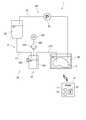
- FIG. 1is a schematic view showing the configuration of the perfusion device 1.
- This perfusion device 1is a device for temporarily storing the liver removed from the donor in vitro until it is transplanted to the recipient.
- the perfusion device 1supplies the perfusate to the liver to perfuse it.
- the target organ of the perfusion device 1is not limited to the liver, but may be the kidney, spleen, or other organ.
- the liver 9is housed in the reactor 90.
- the reactor 90internally houses the organ preservation solution and the liver 9 connected to the perfusion device 1.
- a cup-shaped (bottomed tubular) containeris used for the reactor 90.
- the perfusion device 1has a reservoir 20, a perfusate supply path 30, a perfusate recovery path 40, and a control unit 10.
- the reservoir 20is a container for storing the perfusate.
- the reservoir 20 of the present embodimentis a soft bag formed by a flexible container such as an IV bag.
- As the perfusateother types of perfusate such as UW may be used.
- a temperature adjusting mechanism for adjusting the temperature of the perfusate stored in the reservoir 20 and a gas exchange mechanism for adding a gas such as oxygen to the perfusate stored in the reservoir 20are provided around the reservoir 20. May be done. Further, such a temperature adjusting mechanism and a gas exchange mechanism may be provided in the perfusate supply path 30. When the gas exchange mechanism is provided in the perfusate supply path 30, the gas exchange mechanism is arranged on the upstream side of the degassing unit 32 described later.
- the perfusate supply path 30supplies the perfusate from the reservoir 20 to the liver 9 housed in the reactor 90.
- the perfusate supply path 30has a supply pipe 31 and a degassing unit 32 inserted in the supply pipe 31.
- the supply pipe 31is a pipe for supplying the perfusate from the reservoir 20 to the liver 9 housed in the reactor 90.
- the supply pipe 31includes a first supply pipe 311 and a second supply pipe 312.
- the first supply pipe 311is a pipe for supplying the perfusate from the reservoir 20 to the degassing unit 32.
- One end of the first supply pipe 311communicates with the inside of the reservoir 20 at the lower part of the reservoir 20.
- the other end of the first supply pipe 311communicates with the inside of the air chamber 321 described later of the degassing unit 32.
- the second supply pipe 312is a pipe for supplying the perfusate from the degassing unit 32 to the liver 9 housed in the reactor 90.
- One end of the second supply pipe 312communicates with the inside of the air chamber 321 at the lower part of the air chamber 321.
- the other end of the second supply pipe 312is connected to the blood vessel for the inflow of the perfusate of the liver 9.
- the other end of the second supply pipe 312is ligated to the portal vein or hepatic artery of the liver 9 and communicated with each other.
- the degassing unit 32has an air chamber 321, a degassing pipe 322, a degassing pump 323, and a hydrophobic filter 324.
- the air chamber 321is a container for temporarily storing the perfusate inside and separating the perfusate itself from the air bubbles contained in the perfusate.
- the air chamber 321is provided with a level sensor 320 that detects the height of the perfusate in the air chamber 321.
- a level sensor 320for example, an optical level sensor that projects and receives light into the air chamber 321 to confirm the presence of the perfusate is used.
- the control unit 10controls the degassing pump 323 so that a constant gas layer is formed on the upper part inside the air chamber 321 according to the signal from the level sensor 320.
- the degassing pipe 322is a pipe for discharging gas from the gas layer above the air chamber 321. One end of the degassing pipe 322 communicates with the gas layer above the air chamber 321. The other end of the degassing pipe 322 is connected to the degassing pump 323. Details of the degassing pump 323 will be described later.
- a hydrophobic filter 324is inserted in the degassing pipe 322. As a result, it is possible to prevent the perfusate and water in the air chamber 321 from being mixed into the degassing pump 323 side.
- the reservoir 20is located above the air chamber 321 and the liver 9.
- the perfusate in the reservoir 20is supplied to the liver 9 via the perfusate supply path 30 by the head difference between the air chamber 321 and the liver 9.
- the perfusate supplied to the liver 9circulates in the liver 9 and then drains blood from the liver 9 such as the inferior vena cava (SH-IVC) and the inferior vena cava (IH-IVC). It flows out of the vein into the reactor 90.
- SH-IVCinferior vena cava
- IH-IVCinferior vena cava
- the perfusate recovery route 40collects the perfusate discharged from the liver 9 and accumulated in the reactor 90, and returns to the reservoir 20.
- the perfusate recovery path 40has a recovery pipe 41 and a liquid feed pump 42.
- the recovery pipe 41is a pipe for sending the perfusate liquid from the reactor 90 to the reservoir 20.
- One end of the recovery pipe 41is arranged in the perfusate collected in the lower part of the reactor 90.
- the other end of the recovery pipe 41is communicated with the reservoir 20.
- the liquid feed pump 42is inserted into the recovery pipe 41.
- the liquid feed pump 42generates a flow of perfusate from the reactor 90 to the reservoir 20 in the recovery pipe 41.
- a centrifugal pump having an impelleris used as the liquid feed pump 42.
- the perfusate collected in the reactor 90is returned to the reservoir 20.
- the perfusion device 1 of the present embodimenthas a configuration in which the perfusate discharged from the liver 9 is refluxed to the reservoir 20, but the present invention is not limited to this.
- the perfusate discharged from the liver 9may not be returned to the reservoir 20 and may be discarded or stored in another container.
- each part of the reservoir 20, the perfusate supply path 30, and the perfusate recovery path 40may be appropriately provided with a measurement unit for detecting pH and a specific component. Further, a pressure gauge, a flow meter, an electromagnetic valve for controlling communication, and the like may be inserted in the supply pipe 31 and the recovery pipe 41.
- the control unit 10is a part for controlling the operation of each part in the perfusion device 1.
- the control unit 10is composed of, for example, a computer having an arithmetic processing unit 11 such as a CPU, a memory 12 such as a RAM, and a storage unit 13 such as a hard disk drive.
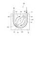
- FIG. 2is a plan view of the degassing pump 323 of the present embodiment.
- the degassing pump 323includes a gas pipe 51, a frame 52 for fixing the gas pipe 51, a plurality of rollers 53, a roller holder 54, and a motor 55.
- the degassing pump 323is a so-called roller tube pump that creates a gas flow in the gas pipe 51 by squeezing the gas pipe 51 while the roller 53 rotates.
- the flexible pipeis crushed using a roller, and the fluid in the flexible pipe is sucked from the upstream side by moving the roller while maintaining the crushed state of the flexible pipe. Therefore, in the roller tube pump, the upstream side of the roller tube pump can be kept in a closed system (airtight) without the need for a check valve.
- the gas pipe 51is a flexible pipe made of an elastomer.
- the upstream end of the gas pipe 51is communicated with the downstream end of the degassing pipe 322.
- the gas pipe 51 and the degassing pipe 322may be integrally formed.
- the frame 52is a member for fixing the outer peripheral portion of the gas pipe 51 that is bent and arranged.
- the frame 52has a recess 521 in which the gas pipe 51 is arranged.
- the edge portion of the recess 521has an arcuate arcuate portion 522 centered on the rotation center 50 and an open portion 523 open from both ends of the arcuate portion 522 to the end portion of the frame 52.
- the gas pipe 51is arranged along the edge of the recess 521 of the frame 52. As a result, the gas pipe 51 is bent and arranged along the edge of the recess 521. Therefore, the outer peripheral portion of the bent gas pipe 51 is along the edge portion of the recess 521.
- the plurality of rollers 53are attached to the roller holder 54 that rotates around the rotation center 50.
- the degassing pump 323 of this embodimenthas two rollers 53.
- the number of rollers 53 included in the degassing pump 323may be two or three or more.
- the two rollers 53are rotatably attached to the roller holder 54 about the roller shaft 530.
- the roller 53rotates around the rotation center 50 as the roller shaft 530 rotates with the rotation of the roller holder 54, and when the surface of the roller 53 comes into contact with the gas pipe 51, the roller 53 rolls on the surface of the gas pipe 51. It rotates around the roller shaft 530.
- the roller 53 and the roller holder 54are arranged on the inner peripheral side of the gas pipe 51 which is bent and arranged along the recess 521.
- the roller holder 54is rotated about the rotation center 50 by the motor 55.
- the motor 55for example, a brushless motor is used.
- the rotation directions of the roller 53 and the roller holder 54are indicated by solid arrows. Further, the direction in which the gas flows in the gas pipe 51 is indicated by a broken line arrow.
- the two rollers 53are arranged 180 ° rotationally symmetric with respect to the rotation center 50.
- the arcuate portion 522 of the frame 52has an arcuate shape centered on the rotation center 50. Further, the difference between the distance from the rotation center 50 to the arcuate portion 522 and the distance from the rotation center 50 to the outer end portion of the roller 53 is smaller than the outer diameter of the gas pipe 51. More specifically, the difference between the distance from the center of rotation 50 to the arcuate portion 522 and the distance from the center of rotation 50 to the outer end of the roller 53 is substantially the same as twice the thickness of the tube of the gas pipe 51. be. Therefore, the roller 53 rotates while pressing and crushing the gas pipe 51 inside the arcuate portion 522. As a result, the gas in the gas pipe 51 is pushed out in the rotational direction of the roller 53 and the roller holder 54, and a gas flow is generated in the gas pipe 51.
- the roller 53presses the gas pipe 51 inside the arcuate portion 522, the gas pipe 51 is blocked. Further, the arcuate portion 522 has a central angle of 180 ° or more centered on the rotation center 50. Therefore, at least one of the two rollers 53 is arranged inside the arcuate portion 522. Therefore, in the degassing pump 323, airtightness is ensured by closing at least one position of the gas pipe 51.
- the air chamber 321is provided with a level sensor 320.
- the level sensor 320confirms the presence of the perfusate at two heights, H level and L level, in the air chamber 321.
- the H levelindicates a position higher than the L level.
- the control unit 10determines that the liquid level of the perfusate is lower than the L level in the detection signal from the level sensor 320, the control unit 10 drives the degassing pump 323. Further, when the control unit 10 determines that the liquid level of the perfusate is higher than the H level in the detection signal from the level sensor 320, the control unit 10 stops the drive of the degassing pump 323. As a result, the height of the perfusate level in the air chamber 321 can be maintained between the H level and the L level. As a result, the height of the gas layer formed on the upper part of the air chamber 321 can be maintained within a predetermined range.
- the perfusateflows due to the difference in head with the organ when the air is opened. It is necessary to adjust the height with the organ.
- the flow of the perfusate in the perfusate supply pathmay stop.
- the gas in the air chamber 321is exhausted by the degassing pump 323, which is a roller tube pump, so that the gas in the air chamber 321 is discharged while keeping the perfusate supply path 30 in a closed system (airtight). It can be discharged properly. Therefore, the perfusate supplied to the organ (liver 9) without limiting the height of the organ (liver 9) in the perfusion device 1 and without stopping the supply of the perfusate to the organ (liver 9). Bubbles can be removed.
- FIG. 3is a schematic view showing the configuration of the perfusion device 1A.
- those having the same reference numerals as those in FIG. 1have the same configurations as those in the first embodiment.
- the perfusate recovery path 40A of the perfusion device 1Ahas a configuration in which the second degassing unit 43A is inserted into the perfusion solution recovery path 40 of the perfusion device 1 according to the first embodiment. That is, the perfusate recovery path 40A has a recovery pipe 41A, a liquid feed pump 42A, and a second degassing unit 43A.
- the recovery pipe 41Asends the perfusate from the first recovery pipe 411A for sending the perfusate discharged from the liver 9 to the second degassing unit 43A and the perfusate from the second degassing unit 43A to the reservoir 20.
- a second recovery pipe 412Afor the purpose.
- the liquid feed pump 42Ais inserted in the second recovery pipe 412A. That is, the second degassing unit 43A is arranged on the upstream side of the liquid feeding pump 42A.
- the second degassing unit 43Ahas the same configuration as the degassing unit 32.
- the second degassing unit 43Ahas a second air chamber 431A, a second degassing pipe 432A, a second degassing pump 433A, and a hydrophobic filter 434A.
- the second degassing pump 433Ais a so-called roller tube pump that creates a gas flow in the gas piping by squeezing the flexible gas piping while rotating a plurality of rollers.
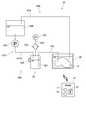
- FIG. 4is a schematic view showing the configuration of the perfusion device 1B.
- those having the same reference numerals as those in FIG. 1have the same configurations as those in the first embodiment.
- the reservoir 20Bis not a soft bag but a hard and airtight container. Further, in the perfusion device 1B, the liquid feed pump 33B is provided not in the perfusate recovery path 40B but in the perfusate supply path 30B.
- the liquid feed pump 33Bis inserted into the first supply pipe 311B that supplies the perfusate from the reservoir 20B to the air chamber 321.
- the liquid feed pumpis not inserted in the recovery pipe 41B of the perfusate recovery path 40B.
- the perfusateis supplied from the reservoir 20B to the liver 9 via the degassing unit 32.
- the pressure in the reservoir 20Bdecreases, so that the pressure in the recovery pipe 41B decreases.
- the perfusate discharged from the liver 9 and accumulated in the reactor 90is sucked into the recovery pipe 41B and returned to the reservoir 20B.
- the position of the liquid feeding pumpmay be appropriately changed depending on the type of the reservoir 20B.
- FIG. 5is a plan view of the degassing pump 323C according to a modified example.
- the degassing pump 323Cis a pump used for the degassing unit provided in the perfusate supply path. Similar to the degassing pump 323 of the first embodiment, the degassing pump 323C is a so-called roller that causes a gas flow in the gas piping 51C by squeezing the gas piping 51C while rotating a plurality of rollers 53C. It is a tube pump.
- the degassing pump 323 of the first embodimenthas two rollers 53, but this degassing pump 323C has three rollers 53C.
- the three rollers 53Care arranged 120 ° rotationally symmetric (three-fold symmetric) with respect to the rotation center 50C.
- the arcuate portion 522C of the frame 52C of the degassing pump 323Chas a central angle of 180 ° about the rotation center 50C, similarly to the frame 52 of the first embodiment.
- the perfusate recovery routerecovers the perfusate discharged from the liver into the reactor, but the present invention is not limited to this.
- the upstream end of the recovery pipeis connected to the inferior vena cava (SH-IVC) or inferior vena cava (IH-IVC) of the liver, and the perfusate recovery route 40 is perfusate from the connected blood vessel. May be configured to collect.
- the perfusate supply route and the perfusate recovery route of the perfusion apparatusare one each, but the present invention is not limited to this.
- the perfusifiermay have two perfusate supply pathways to supply the perfusate to the portal vein of the liver and the hepatic artery, respectively.
- the perfusion devicehas two routes for collecting perfusate, and collects perfusate from each of the inferior vena cava (SH-IVC) and the inferior vena cava (IH-IVC) of the liver. May be good.
Landscapes
- Life Sciences & Earth Sciences (AREA)
- Health & Medical Sciences (AREA)
- Engineering & Computer Science (AREA)
- Dentistry (AREA)
- General Health & Medical Sciences (AREA)
- Wood Science & Technology (AREA)
- Zoology (AREA)
- Environmental Sciences (AREA)
- Agricultural Chemicals And Associated Chemicals (AREA)
Abstract
Description
Translated fromJapanese本発明は、摘出された臓器に対して灌流処理を行う灌流装置に関する。The present invention relates to a perfusion device that perfuses an excised organ.
肝臓移植等の移植手術では、ドナーから臓器を摘出した後、当該臓器をレシピエントへ移植するまでの間、一時的に臓器を保存する。摘出された臓器を移植可能な状態で保存するため、種々の保存方法や灌流方法が開発されている。摘出した臓器を保存するためには、例えば、細胞の代謝を抑制するために臓器内血液を低温の臓器保存液に置き換えてから、低温の保存液に浸漬する単純冷却法が知られている。また、保存している臓器内の老廃物の除去を目的として、臓器内血管網に灌流液を灌流させる灌流保存法が知られている。In transplant surgery such as liver transplantation, the organ is temporarily preserved after the organ is removed from the donor until the organ is transplanted to the recipient. Various preservation methods and perfusion methods have been developed to preserve the excised organs in a transplantable state. In order to preserve the excised organs, for example, a simple cooling method is known in which the blood in the organ is replaced with a low-temperature organ preservation solution in order to suppress the metabolism of cells, and then the blood is immersed in the low-temperature preservation solution. Further, a perfusion preservation method is known in which a perfusate is perfused into a vascular network in an organ for the purpose of removing waste products in the preserved organ.
臓器を体外で保存する従来の装置については、例えば、特許文献1に記載されている。A conventional device for storing an organ outside the body is described in, for example,
特許文献1の装置では、送液ポンプによってリザーバから吸引した灌流液を、灌流チューブを介して臓器に供給する構成が開示されている。このように、臓器の灌流処理を行う場合には、臓器に対して配管を接続して、臓器内に灌流液を供給する。The device of
このとき、臓器への空気の混入リスクを低減させるため、臓器への灌流液の供給経路において気泡を除去することが望ましい。特許文献1の装置では、臓器への灌流液の供給経路にバブルトラップが設けられている。At this time, in order to reduce the risk of air entering the organ, it is desirable to remove air bubbles in the supply route of the perfusate to the organ. In the device of
一般的なエアチャンバ(バブルトラップ)による脱気方法では、上部に気体層が設けられたエアチャンバの気体層を定期的に大気開放することにより、灌流液内に含まれる気泡を除去する。このようなエアチャンバでは、大気開放時に臓器との水頭差によって灌流液の流れが生じてしまうため、エアチャンバの液面と臓器との高さを調整する必要がある。In the general degassing method using an air chamber (bubble trap), bubbles contained in the perfusate are removed by periodically opening the gas layer of the air chamber provided with a gas layer at the top to the atmosphere. In such an air chamber, the flow of the perfusate is generated due to the difference in head with the organ when the air chamber is opened, so it is necessary to adjust the height between the liquid level of the air chamber and the organ.
本発明は、このような事情に鑑みなされたものであり、灌流装置における臓器の高さを限定すること無く、臓器に供給する灌流液の気泡を取り除くことができる技術を提供することを目的とする。The present invention has been made in view of such circumstances, and an object of the present invention is to provide a technique capable of removing air bubbles in a perfusate supplied to an organ without limiting the height of the organ in the perfusion device. do.
上記課題を解決するため、本願の第1発明は、臓器に対して灌流処理を行う灌流装置であって、灌流液を貯留するリザーバと、前記リザーバに貯留される前記灌流液を前記臓器に供給する灌流液供給経路と、を有し、前記灌流液供給経路は、前記リザーバ内の前記灌流液を前記臓器へ送液する供給配管と、前記供給配管に介挿され、前記灌流液内の気泡を除去する脱気ユニットと、を有し、前記脱気ユニットは、前記灌流液を一時的に貯留するエアチャンバと、前記エアチャンバの上部の気体層から前記エアチャンバの外部へと気体を排出する脱気ポンプと、を備え、前記脱気ポンプは、フレキシブルな気体配管を複数のローラが回転しながらしごくことで前記気体配管内に気体の流れを生じさせるローラチューブポンプである。In order to solve the above problems, the first invention of the present application is a perfusion device that perfusates an organ, and supplies a reservoir for storing the perfusate and the perfusate stored in the reservoir to the organ. The perfusate supply route has a supply pipe for sending the perfusate in the reservoir to the organ, and a bubble inserted in the supply pipe. The degassing unit has an air chamber that temporarily stores the perfusate and discharges gas from the gas layer above the air chamber to the outside of the air chamber. A degassing pump is provided, and the degassing pump is a roller tube pump that creates a gas flow in the gas pipe by squeezing a flexible gas pipe while rotating a plurality of rollers.
本願の第2発明は、第1発明の灌流装置であって、前記脱気ポンプの有する前記ローラの数は、3つ以上である。The second invention of the present application is the perfusion device of the first invention, and the number of the rollers of the degassing pump is three or more.
本願の第3発明は、第1発明または第2発明の灌流装置であって、前記エアチャンバ内の前記灌流液の液面の高さを検出するレベルセンサと、前記レベルセンサからの検出信号において前記灌流液の液面がLレベルよりも低い場合に、前記脱気ポンプを駆動させ、前記レベルセンサからの検出信号において前記灌流液の液面が前記Lレベルよりも高いHレベルよりも高い場合に、前記脱気ポンプの駆動を停止させる制御部と、をさらに備える。The third invention of the present application is the perfusion device of the first invention or the second invention, in which the level sensor for detecting the height of the perfusate liquid level in the air chamber and the detection signal from the level sensor. When the liquid level of the perfusate is lower than the L level, the degassing pump is driven, and the liquid level of the perfusate is higher than the H level higher than the L level in the detection signal from the level sensor. Further includes a control unit for stopping the drive of the degassing pump.
本願の第4発明は、第1発明から第3発明までのいずれかい1発明の灌流装置であって、前記臓器から排出された前記灌流液を前記リザーバへと還流する灌流液回収経路をさらに有し、前記灌流液回収経路は、前記臓器から前記リザーバへと前記灌流液を送液する回収配管と、前記回収配管に介挿される送液ポンプと、前記送液ポンプの上流側において前記回収配管に介挿され、前記灌流液内の気泡を除去する第2脱気ユニットと、を有し、前記第2脱気ユニットは、前記灌流液を一時的に貯留する第2エアチャンバと、前記第2エアチャンバの上部の気体層から前記第2エアチャンバの外部へと気体を排出する第2脱気ポンプと、を備え、前記第2脱気ポンプは、フレキシブルな気体配管を複数のローラが回転しながらしごくことで前記気体配管内に気体の流れを生じさせるローラチューブポンプである。The fourth invention of the present application is the perfusion apparatus of any one of the first to third inventions, further comprising a perfusate recovery route for returning the perfusate discharged from the organ to the reservoir. The perfusate recovery route includes a recovery pipe for feeding the perfusate from the organ to the reservoir, a liquid feed pump inserted in the recovery pipe, and the recovery pipe on the upstream side of the liquid feed pump. The second degassing unit has a second degassing unit that is inserted into the pump and removes air bubbles in the perfusate, and the second degassing unit has a second air chamber that temporarily stores the perfusate and the first air chamber. A second degassing pump for discharging gas from the gas layer above the two air chambers to the outside of the second air chamber is provided, and the second degassing pump has a plurality of rollers rotating on a flexible gas pipe. It is a roller tube pump that creates a gas flow in the gas pipe by squeezing while squeezing.
本願の第1発明から第4発明によれば、エアチャンバ内の気体をローラチューブポンプで排気することにより、灌流液供給経路を閉鎖系(気密)に保ったままエアチャンバ内の気体を適切に排出することができる。したがって、灌流装置における臓器の高さを限定すること無く、かつ、臓器への灌流液の供給を停止すること無く、臓器に供給する灌流液の気泡を取り除くことができる。According to the first to fourth inventions of the present application, by exhausting the gas in the air chamber with a roller tube pump, the gas in the air chamber is appropriately maintained while keeping the perfusate supply path in a closed system (airtight). Can be discharged. Therefore, it is possible to remove air bubbles in the perfusate supplied to the organ without limiting the height of the organ in the perfusion device and without stopping the supply of the perfusate to the organ.
特に、本願の第2発明によれば、脱気ポンプにおける気密性がより高まる。In particular, according to the second invention of the present application, the airtightness of the degassing pump is further enhanced.
特に、本願の第3発明によれば、エアチャンバの上部に形成される気体層の高さを、所定の範囲に維持できる。In particular, according to the third invention of the present application, the height of the gas layer formed on the upper part of the air chamber can be maintained within a predetermined range.
特に、本願の第4発明によれば、送液ポンプに気泡が混入するのを抑制できる。In particular, according to the fourth invention of the present application, it is possible to suppress air bubbles from being mixed into the liquid feed pump.
以下、本発明の実施形態について、図面を参照しつつ説明する。本願において「臓器」は、ヒトの臓器であってもよいし、非ヒト動物の臓器であってもよい。したがって、「ドナー」および「レシピエント」は、ヒトであってもよいし、非ヒト動物であってもよい。また、非ヒト動物は、マウスおよびラットを含む齧歯類、ブタ、ヤギおよびヒツジを含む有蹄類、チンパンジーを含む非ヒト霊長類、その他の非ヒトほ乳動物であってもよいし、ほ乳動物以外の動物であってもよい。Hereinafter, embodiments of the present invention will be described with reference to the drawings. In the present application, the "organ" may be a human organ or a non-human animal organ. Therefore, the "donor" and "recipient" may be human or non-human animals. In addition, non-human animals may be rodents including mice and rats, ungulates including pigs, goats and sheep, non-human primates including chimpanzees, and other non-human mammals, and mammals. It may be an animal other than.
<1.第1実施形態>
<1-1.灌流装置の構成>
本発明の第1実施形態に係る灌流装置1について、図1を参照しつつ説明する。図1は、灌流装置1の構成を示した概略図である。この灌流装置1は、ドナーから摘出した肝臓を、レシピエントへ移植するまでの間、体外で一時的に保存するための装置である。灌流装置1は、当該肝臓に灌流液を供給して灌流を行う。なお、灌流装置1の対象臓器は肝臓に限られず、腎臓、脾臓、その他の臓器であってもよい。<1. First Embodiment>
<1-1. Perfusion device configuration>
The
灌流装置1によって灌流処理が行われる際に、肝臓9はリアクタ90内に収容される。リアクタ90は、内部に臓器保存液と、灌流装置1に接続された肝臓9とを収容する。リアクタ90には、例えば、カップ状(有底筒状)の容器が用いられる。When the perfusion treatment is performed by the
図1に示すように、灌流装置1は、リザーバ20、灌流液供給経路30、灌流液回収経路40、および制御部10を有する。As shown in FIG. 1, the
リザーバ20は、灌流液を貯留する容器である。本実施形態のリザーバ20は、点滴バッグのようなフレキシブルな容器によって形成されるソフトバッグである。リザーバ20に貯留される灌流液には、例えば、ETK液が用いられる。灌流液には、UW液等のその他の種類の灌流液が用いられてもよい。The
また、リザーバ20の周囲には、リザーバ20内に貯留される灌流液の温度を調整する温度調整機構や、リザーバ20内に貯留される灌流液に酸素等の気体を添加するガス交換機構が備えられてもよい。また、このような温度調整機構やガス交換機構は、灌流液供給経路30に備えられてもよい。なお、ガス交換機構が灌流液供給経路30に備えられる場合、ガス交換機構は後述する脱気ユニット32の上流側に配置される。Further, around the
灌流液供給経路30は、リザーバ20からリアクタ90内に収容された肝臓9へと灌流液を供給する。灌流液供給経路30は、供給配管31と、供給配管31に介挿される脱気ユニット32とを有する。The
供給配管31は、リザーバ20からリアクタ90内に収容された肝臓9へと灌流液を供給するための配管である。供給配管31は、第1供給配管311と、第2供給配管312とを含む。The
第1供給配管311は、リザーバ20から脱気ユニット32へと灌流液を供給するための配管である。第1供給配管311の一端は、リザーバ20の下部においてリザーバ20内と連通接続する。第1供給配管311の他端は、脱気ユニット32の後述するエアチャンバ321の内部と連通接続する。The
第2供給配管312は、脱気ユニット32からリアクタ90内に収容された肝臓9へと灌流液を供給するための配管である。第2供給配管312の一端は、エアチャンバ321の下部においてエアチャンバ321内と連通接続する。第2供給配管312の他端は、肝臓9の灌流液流入用の血管と接続される。具体的には、第2供給配管312の他端は、肝臓9の門脈または肝動脈に結紮され、連通接続される。The
脱気ユニット32は、エアチャンバ321、脱気配管322、脱気ポンプ323、および疎水フィルタ324を有する。The degassing
エアチャンバ321は、内部に灌流液を一時的に貯留して、灌流液自体と、灌流液に含まれる気泡とを分離するための容器である。エアチャンバ321には、エアチャンバ321内の灌流液の液面の高さを検出するレベルセンサ320が設けられている。レベルセンサ320には、例えば、エアチャンバ321内に光を投光・受光して灌流液の存在を確認する光学式のレベルセンサが用いられる。制御部10は、レベルセンサ320からの信号に従って、エアチャンバ321内部において、上部に一定の気体層が形成されるように脱気ポンプ323を制御する。The
脱気配管322は、エアチャンバ321の上部の気体層から気体を排出するための配管である。脱気配管322の一端は、エアチャンバ321の上部の気体層に連通接続する。脱気配管322の他端は、脱気ポンプ323に接続される。脱気ポンプ323の詳細については後述する。The
脱気配管322には、疎水フィルタ324が介挿される。これにより、エアチャンバ321内の灌流液や水分が脱気ポンプ323側へと混入するのが抑制される。A
リザーバ20は、エアチャンバ321および肝臓9よりも上方に配置される。リザーバ20内の灌流液は、エアチャンバ321および肝臓9との水頭差によって、灌流液供給経路30を介して肝臓9へと供給される。肝臓9に供給された灌流液は、肝臓9内を循環した後、肝上部下大静脈(SH-IVC)や肝下部下大静脈(IH-IVC)等の肝臓9から血液を排出するための血管からリアクタ90内へと流出する。The
灌流液回収経路40は、肝臓9から排出され、リアクタ90内に溜まった灌流液を回収し、リザーバ20へと還流する。灌流液回収経路40は、回収配管41および送液ポンプ42を有する。The
回収配管41は、リアクタ90からリザーバ20へと灌流液を送液するための配管である。回収配管41の一端は、リアクタ90の下部に溜まった灌流液内に配置される。回収配管41の他端は、リザーバ20に連通接続される。The
送液ポンプ42は、回収配管41に介挿される。送液ポンプ42は、回収配管41内にリアクタ90からリザーバ20へと向かう灌流液の流れを発生させる。送液ポンプ42には、例えば、羽根車を有する遠心ポンプが用いられる。送液ポンプ42が駆動されると、リアクタ90内に溜まった灌流液がリザーバ20へと還流される。The
本実施形態の灌流装置1は、肝臓9から排出された灌流液をリザーバ20へと還流させる構成であったが、本発明はこれに限られない。肝臓9から排出された灌流液は、リザーバ20へと還流させず、廃棄したり、他の容器に貯留したりしてもよい。The
なお、リザーバ20、灌流液供給経路30および灌流液回収経路40の各部には、pHや、特定の成分を検出するための計測ユニットが適宜備えられていてもよい。また、供給配管31および回収配管41には、圧力計、流量計、および連通を制御する電磁弁等が介挿されていてもよい。Note that each part of the
制御部10は、灌流装置1内の各部を動作制御するための部位である。図1中に概念的に示したように、制御部10は、例えば、CPU等の演算処理部11、RAM等のメモリ12、および、ハードディスクドライブ等の記憶部13を有するコンピュータにより構成される。The
<1-2.脱気ユニットについて>
次に、脱気ユニット32について、図1および図2を参照しつつ、詳細に説明する。まず、脱気ユニット32の有する脱気ポンプ323について、図2を参照しつつ説明する。図2は、本実施形態の脱気ポンプ323の平面図である。<1-2. About the degassing unit>
Next, the degassing
図2に示すように、脱気ポンプ323は、気体配管51と、気体配管51を固定するフレーム52と、複数のローラ53と、ローラホルダ54と、モータ55とを有する。脱気ポンプ323は、気体配管51をローラ53が回転しながらしごくことで気体配管51内に気体の流れを生じさせる、所謂ローラチューブポンプである。As shown in FIG. 2, the
ローラチューブポンプでは、ローラを用いてフレキシブル配管を押しつぶし、フレキシブル配管を押しつぶした状態を維持しながらローラを移動することで、フレキシブル配管内の流体を上流側から吸引する。このため、ローラチューブポンプでは、逆止弁を必要とすること無く、ローラチューブポンプの上流側を閉鎖系(気密)に保つことができる。In the roller tube pump, the flexible pipe is crushed using a roller, and the fluid in the flexible pipe is sucked from the upstream side by moving the roller while maintaining the crushed state of the flexible pipe. Therefore, in the roller tube pump, the upstream side of the roller tube pump can be kept in a closed system (airtight) without the need for a check valve.
気体配管51は、エラストマーで形成されたフレキシブル配管である。気体配管51の上流側の端部は、脱気配管322の下流側の端部と連通接続される。なお、気体配管51と脱気配管322とは、一体に形成されていてもよい。The
フレーム52は、屈曲して配置される気体配管51の外周部を固定するための部材である。フレーム52は、気体配管51が内部に配置される凹部521を有する。凹部521の縁部は、回転中心50を中心とした円弧状の円弧状部522と、円弧状部522の両端からフレーム52の端部まで開放された開放部523とを有する。The
脱気ポンプ323の使用時には、フレーム52の凹部521の縁部に沿って気体配管51が配置される。これによって、気体配管51は、凹部521の縁部に沿って屈曲して配置される。このため、屈曲した気体配管51の外周部は、凹部521の縁部に沿う。When the
複数のローラ53は、回転中心50を中心として回転するローラホルダ54に取り付けられる。本実施形態の脱気ポンプ323は、2つのローラ53を有する。脱気ポンプ323の有するローラ53の数は、2つであってもよいし、3つ以上であってもよい。The plurality of
2つのローラ53は、ローラホルダ54に対して、ローラ軸530を中心として回転可能に取り付けられる。これによって、ローラ53は、ローラホルダ54の回転に伴ってローラ軸530が回転中心50を中心として回転するとともに、ローラ53の表面が気体配管51に接触すると、気体配管51の表面を転がるようにローラ軸530を中心として回転する。The two
ローラ53およびローラホルダ54は、凹部521に沿って屈曲して配置された気体配管51の内周側に配置される。ローラホルダ54は、モータ55によって、回転中心50を中心として回転する。モータ55には、例えば、ブラシレスモータが用いられる。図2中には、ローラ53およびローラホルダ54の回転方向が実線矢印で示されている。また、気体配管51内の気体の流れる方向が破線矢印で示されている。The
2つのローラ53は、回転中心50に対して180°回転対称に配置される。フレーム52の円弧状部522は、回転中心50を中心とした円弧状である。また、回転中心50から円弧状部522までの距離と回転中心50からローラ53の外端部までの距離との差分は、気体配管51の外径よりも小さい。より具体的には、回転中心50から円弧状部522までの距離と回転中心50からローラ53の外端部までの距離との差分は、気体配管51のチューブの厚みの2倍と略同一である。このため、ローラ53が円弧状部522の内側において、気体配管51を押圧して押しつぶしながら回転する。これにより、気体配管51内の気体が、ローラ53およびローラホルダ54の回転方向に押し出され、気体配管51内に気体の流れが生じる。The two
ここで、円弧状部522の内側においてローラ53が気体配管51を押圧する際に、気体配管51が閉塞される。また、円弧状部522は回転中心50を中心とした中心角が180°以上である。このため、2つのローラ53の少なくとも一方は、円弧状部522の内側に配置される。したがって、この脱気ポンプ323において、気体配管51の少なくとも1箇所が閉塞されることによって、気密性が確保されている。Here, when the
上記の通り、エアチャンバ321には、レベルセンサ320が設けられている。本実施形態では、レベルセンサ320は、エアチャンバ321内のHレベルおよびLレベルの2箇所の高さにおいて灌流液の存在を確認する。Hレベルは、Lレベルよりも高い位置を示す。第1供給配管31から供給される灌流液に気体が混入している場合、エアチャンバ321において当該気体がトラップされることにより、エアチャンバ321内の灌流液の液面の高さは、徐々に低下する。As described above, the
制御部10は、レベルセンサ320からの検出信号において灌流液の液面がLレベルよりも低いと判断すると、脱気ポンプ323を駆動させる。また、制御部10は、レベルセンサ320からの検出信号において灌流液の液面がHレベルよりも高いと判断すると、脱気ポンプ323の駆動を停止させる。これにより、エアチャンバ321内の灌流液の液面の高さをHレベルとLレベルとの間に保持できる。その結果、エアチャンバ321の上部に形成される気体層の高さを所定の範囲に保持できる。When the
大気開放によってエアチャンバ内に溜まった気体を排出する一般的な脱気ユニットでは、大気開放時に臓器との水頭差によって灌流液の流れが生じてしまうため、エアチャンバ内の灌流液の液面と臓器との高さを調整する必要がある。また、大気開放時には灌流液供給経路における灌流液の流れが止まる場合がある。In a general degassing unit that discharges the gas accumulated in the air chamber by opening to the atmosphere, the perfusate flows due to the difference in head with the organ when the air is opened. It is necessary to adjust the height with the organ. In addition, when the air is open to the atmosphere, the flow of the perfusate in the perfusate supply path may stop.
この灌流装置1では、エアチャンバ321内の気体をローラチューブポンプである脱気ポンプ323で排気することにより、灌流液供給経路30を閉鎖系(気密)に保ったままエアチャンバ321内の気体を適切に排出することができる。したがって、灌流装置1における臓器(肝臓9)の高さを限定すること無く、かつ、臓器(肝臓9)への灌流液の供給を停止すること無く、臓器(肝臓9)に供給する灌流液の気泡を取り除くことができる。In this
<2.第2実施形態>
続いて、本発明の第2実施形態に係る灌流装置1Aについて、図3を参照しつつ説明する。図3は、灌流装置1Aの構成を示した概略図である。図3中の構成のうち、図1中と同じ符号を付したものは、第1実施形態と同等の構成である。<2. Second Embodiment>
Subsequently, the
この灌流装置1Aの灌流液回収経路40Aは、第1実施形態に係る灌流装置1の灌流液回収経路40に第2脱気ユニット43Aを介挿した構成となっている。すなわち、灌流液回収経路40Aは、回収配管41Aと、送液ポンプ42Aと、第2脱気ユニット43Aとを有する。The
回収配管41Aは、肝臓9から排出された灌流液を第2脱気ユニット43Aへと送液するための第1回収配管411Aと、第2脱気ユニット43Aからリザーバ20へと灌流液を送液するための第2回収配管412Aとを含む。送液ポンプ42Aは、第2回収配管412Aに介挿される。すなわち、第2脱気ユニット43Aは、送液ポンプ42Aよりも上流側に配置される。The
第2脱気ユニット43Aは、脱気ユニット32と同等の構成を有している。第2脱気ユニット43Aは、第2エアチャンバ431A、第2脱気配管432A、第2脱気ポンプ433Aおよび疎水フィルタ434Aを有する。The
第2脱気ポンプ433Aは、脱気ポンプ323と同様に、フレキシブルな気体配管を複数のローラが回転しながらしごくことで当該気体配管内に気体の流れを生じさせる、所謂ローラチューブポンプである。Similar to the
灌流液に赤血球が添加されている場合、送液ポンプ42Aとして、赤血球が溶血しにくい羽根車式の遠心ポンプを用いることが好ましい。このような遠心ポンプでは、ポンプ内に気泡が混入すると、ポンプの回転が阻害される場合がある。そこで、送液ポンプ42Aの上流側に第2脱気ユニット43Aを配置することにより、リアクタ90内において灌流液に気泡が混入した場合であっても、送液ポンプ42Aに気泡が混入するのを抑制できる。When red blood cells are added to the perfusate, it is preferable to use an impeller-type centrifugal pump as the liquid feed pump 42A, which makes it difficult for red blood cells to hemolyze. In such a centrifugal pump, if air bubbles are mixed in the pump, the rotation of the pump may be hindered. Therefore, by arranging the
<3.第3実施形態>
続いて、本発明の第3実施形態に係る灌流装置1Bについて、図4を参照しつつ説明する。図4は、灌流装置1Bの構成を示した概略図である。図4中の構成のうち、図1中と同じ符号を付したものは、第1実施形態と同等の構成である。<3. Third Embodiment>
Subsequently, the
この灌流装置1Bでは、リザーバ20Bがソフトバッグではなく、硬質かつ気密な容器である。また、この灌流装置1Bでは、送液ポンプ33Bが灌流液回収経路40Bではなく、灌流液供給経路30Bに備えられる。In this
具体的には、灌流液供給経路30Bにおいて、送液ポンプ33Bが、リザーバ20Bからエアチャンバ321へと灌流液を供給する第1供給配管311Bに介挿される。一方、灌流液回収経路40Bの回収配管41Bには、送液ポンプが介挿されていない。Specifically, in the
このような灌流装置1Bにおいて、送液ポンプ33Bを駆動させると、リザーバ20Bから脱気ユニット32を介して肝臓9へと灌流液が供給される。これにより、リザーバ20B内の圧力が低下するため、回収配管41B内の圧力が低下する。その結果、肝臓9から排出され、リアクタ90内に溜まった灌流液が回収配管41B内に吸引され、リザーバ20Bへと還流される。When the
このように、リザーバ20Bの種類によって、送液用のポンプの位置を適宜変更してもよい。In this way, the position of the liquid feeding pump may be appropriately changed depending on the type of the
<4.変形例>
以上、本発明の実施形態について説明したが、本発明は、上記の実施形態に限定されるものではない。<4. Modification example>
Although the embodiments of the present invention have been described above, the present invention is not limited to the above embodiments.
図5は、一変形例に係る脱気ポンプ323Cの平面図である。この脱気ポンプ323Cは、灌流液供給経路に設けられる脱気ユニットに用いられるポンプである。脱気ポンプ323Cは、上記の第1実施形態の脱気ポンプ323と同様に、気体配管51Cを複数のローラ53Cが回転しながらしごくことで気体配管51C内に気体の流れを生じさせる、所謂ローラチューブポンプである。FIG. 5 is a plan view of the
第1実施形態の脱気ポンプ323は2つのローラ53を有したが、この脱気ポンプ323Cは3つのローラ53Cを有する。3つのローラ53Cは、回転中心50Cに対して120°回転対称(3回対称)に配置される。また、この脱気ポンプ323Cのフレーム52Cの円弧状部522Cは、第1実施形態のフレーム52と同様に、回転中心50Cを中心とした中心角が180°である。The
円弧状部522Cの中心角が同じである場合、ローラ53Cの数が多いほど、複数のローラ53Cが円弧状部522Cの内側に配置され、気体配管51Cを押圧する期間が長くなる。これにより、万が一、製造誤差やセッティング上の誤差により、ローラ53Cによる気体配管51Cへの押圧力が弱くなる箇所がある場合や、気体配管51Cへの押圧力が弱いローラ53Cがある場合であっても、脱気ポンプ323C全体としての気密性が低下するのを抑制できる。When the central angle of the arc-shaped
また、上記の実施形態では、灌流液回収経路が肝臓からリアクタ内に排出された灌流液を回収したが、本発明はこれに限られない。例えば、回収配管の上流側端部が肝臓の肝上部下大静脈(SH-IVC)または肝下部下大静脈(IH-IVC)と接続され、灌流液回収経路40は接続された血管から灌流液を回収する構成であってもよい。Further, in the above embodiment, the perfusate recovery route recovers the perfusate discharged from the liver into the reactor, but the present invention is not limited to this. For example, the upstream end of the recovery pipe is connected to the inferior vena cava (SH-IVC) or inferior vena cava (IH-IVC) of the liver, and the
また、上記の実施形態では、灌流装置の有する灌流液供給経路および灌流液回収経路がそれぞれ1つずつであるが、本発明はこれに限られない。例えば、灌流装置が灌流液供給経路を2つ有しており、肝臓の門脈と肝動脈とのそれぞれに灌流液を供給してもよい。また、灌流装置が灌流液回収経路を2つ有しており、肝臓の肝上部下大静脈(SH-IVC)と肝下部下大静脈(IH-IVC)とのそれぞれから灌流液を回収してもよい。Further, in the above embodiment, the perfusate supply route and the perfusate recovery route of the perfusion apparatus are one each, but the present invention is not limited to this. For example, the perfusifier may have two perfusate supply pathways to supply the perfusate to the portal vein of the liver and the hepatic artery, respectively. In addition, the perfusion device has two routes for collecting perfusate, and collects perfusate from each of the inferior vena cava (SH-IVC) and the inferior vena cava (IH-IVC) of the liver. May be good.
また、上記の実施形態や変形例に登場した各要素を、矛盾が生じない範囲で、適宜に組み合わせてもよい。Further, each element appearing in the above-described embodiment or modification may be appropriately combined as long as there is no contradiction.
1,1A,1B 灌流装置
9 肝臓
20,20B リザーバ
30,30B 灌流液供給経路
31 供給配管
32 脱気ポンプ
32 脱気ユニット
40,40A,40B 灌流液回収経路
41,41A,41B 回収配管
42,42A,33B 送液ポンプ
43A 第2脱気ユニット
51,51C 気体配管
53,53C ローラ
321 エアチャンバ
323,323C 脱気ポンプ
431A 第2エアチャンバ
433A 第2脱気ポンプ1,1A,
Claims (4)
Translated fromJapanese灌流液を貯留するリザーバと、
前記リザーバに貯留される前記灌流液を前記臓器に供給する灌流液供給経路と、
を有し、
前記灌流液供給経路は、
前記リザーバ内の前記灌流液を前記臓器へ送液する供給配管と、
前記供給配管に介挿され、前記灌流液内の気泡を除去する脱気ユニットと、
を有し、
前記脱気ユニットは、
前記灌流液を一時的に貯留するエアチャンバと、
前記エアチャンバの上部の気体層から前記エアチャンバの外部へと気体を排出する脱気ポンプと、
を備え、
前記脱気ポンプは、フレキシブルな気体配管を複数のローラが回転しながらしごくことで前記気体配管内に気体の流れを生じさせるローラチューブポンプである、灌流装置。A perfusion device that perfuses organs
A reservoir that stores the perfusate and
A perfusate supply route for supplying the perfusate stored in the reservoir to the organ,
Have,
The perfusate supply route is
A supply pipe that sends the perfusate in the reservoir to the organ,
A degassing unit that is inserted into the supply pipe and removes air bubbles in the perfusate.
Have,
The degassing unit
An air chamber that temporarily stores the perfusate and
A degassing pump that discharges gas from the gas layer above the air chamber to the outside of the air chamber,
With
The degassing pump is a perfusion device, which is a roller tube pump that creates a gas flow in the gas pipe by squeezing a flexible gas pipe while rotating a plurality of rollers.
前記脱気ポンプの有する前記ローラの数は、3つ以上である、灌流装置。The perfusion device according to claim 1.
A perfusion device having three or more rollers in the degassing pump.
前記エアチャンバ内の前記灌流液の液面の高さを検出するレベルセンサと、
前記レベルセンサからの検出信号において前記灌流液の液面がLレベルよりも低い場合に、前記脱気ポンプを駆動させ、前記レベルセンサからの検出信号において前記灌流液の液面が前記Lレベルよりも高いHレベルよりも高い場合に、前記脱気ポンプの駆動を停止させる制御部と、
をさらに備える、灌流装置。The perfusion apparatus according to claim 1 or 2.
A level sensor that detects the height of the perfusate in the air chamber and
When the liquid level of the perfusate is lower than the L level in the detection signal from the level sensor, the degassing pump is driven, and the liquid level of the perfusate is lower than the L level in the detection signal from the level sensor. When the H level is higher than the high H level, the control unit that stops the drive of the degassing pump and
Further equipped with a perfusion device.
前記臓器から排出された前記灌流液を前記リザーバへと還流する灌流液回収経路
をさらに有し、
前記灌流液回収経路は、
前記臓器から前記リザーバへと前記灌流液を送液する回収配管と、
前記回収配管に介挿される送液ポンプと、
前記送液ポンプの上流側において前記回収配管に介挿され、前記灌流液内の気泡を除去する第2脱気ユニットと、
を有し、
前記第2脱気ユニットは、
前記灌流液を一時的に貯留する第2エアチャンバと、
前記第2エアチャンバの上部の気体層から前記第2エアチャンバの外部へと気体を排出する第2脱気ポンプと、
を備え、
前記第2脱気ポンプは、フレキシブルな気体配管を複数のローラが回転しながらしごくことで前記気体配管内に気体の流れを生じさせるローラチューブポンプである、灌流装置。The perfusion apparatus according to any one of claims 1 to 3.
It further has a perfusate recovery pathway for refluxing the perfusate drained from the organ to the reservoir.
The perfusate recovery route is
A recovery pipe that sends the perfusate from the organ to the reservoir,
The liquid feed pump inserted in the recovery pipe and
A second degassing unit inserted into the recovery pipe on the upstream side of the liquid feed pump to remove air bubbles in the perfusate.
Have,
The second degassing unit is
A second air chamber that temporarily stores the perfusate, and
A second degassing pump that discharges gas from the gas layer above the second air chamber to the outside of the second air chamber.
With
The second degassing pump is a perfusion device, which is a roller tube pump that creates a gas flow in the gas pipe by squeezing a flexible gas pipe while rotating a plurality of rollers.
Priority Applications (2)
| Application Number | Priority Date | Filing Date | Title |
|---|---|---|---|
| EP21768012.3AEP4118967A4 (en) | 2020-03-10 | 2021-02-10 | PERFUSION DEVICE |
| US17/801,700US20230129709A1 (en) | 2020-03-10 | 2021-02-10 | Perfusion apparatus |
Applications Claiming Priority (2)
| Application Number | Priority Date | Filing Date | Title |
|---|---|---|---|
| JP2020-040687 | 2020-03-10 | ||
| JP2020040687AJP2021143128A (en) | 2020-03-10 | 2020-03-10 | Perfusion device |
Publications (1)
| Publication Number | Publication Date |
|---|---|
| WO2021181985A1true WO2021181985A1 (en) | 2021-09-16 |
Family
ID=77671520
Family Applications (1)
| Application Number | Title | Priority Date | Filing Date |
|---|---|---|---|
| PCT/JP2021/004892CeasedWO2021181985A1 (en) | 2020-03-10 | 2021-02-10 | Perfusion device |
Country Status (4)
| Country | Link |
|---|---|
| US (1) | US20230129709A1 (en) |
| EP (1) | EP4118967A4 (en) |
| JP (1) | JP2021143128A (en) |
| WO (1) | WO2021181985A1 (en) |
Cited By (1)
| Publication number | Priority date | Publication date | Assignee | Title |
|---|---|---|---|---|
| CN114946838A (en)* | 2022-06-29 | 2022-08-30 | 上海健耕医药科技股份有限公司 | Liver low-temperature perfusion preservation device and method |
Citations (9)
| Publication number | Priority date | Publication date | Assignee | Title |
|---|---|---|---|---|
| JPH02124801A (en)* | 1988-11-01 | 1990-05-14 | Olympus Optical Co Ltd | Internal organ preserver |
| JPH03151303A (en) | 1989-11-06 | 1991-06-27 | Olympus Optical Co Ltd | Organ-preservation apparatus |
| WO2006103951A1 (en)* | 2005-03-29 | 2006-10-05 | Terumo Kabushiki Kaisha | Liquid-supplying tube for medical use provided with deaeration module, assembly of medical machines using the liquid-supplying tube for medical use, deaeration module and method of supplying liquid |
| US20120143115A1 (en)* | 2010-12-07 | 2012-06-07 | Lifebridge Medizintechnik Ag | Cardiopulmonary Apparatus And Methods For Preserving Organ Viability |
| WO2017200089A1 (en)* | 2016-05-20 | 2017-11-23 | 株式会社Screenホールディングス | Perfusion apparatus for liver for transplantation, and liver isolation method and liver transplantation method using said apparatus |
| WO2019044354A1 (en)* | 2017-08-29 | 2019-03-07 | 株式会社Screenホールディングス | Organ storage container and perfusion device |
| WO2020004088A1 (en)* | 2018-06-28 | 2020-01-02 | 株式会社Screenホールディングス | Perfusion device and perfusion method |
| WO2021005988A1 (en)* | 2019-07-08 | 2021-01-14 | 株式会社Screenホールディングス | Perfusion device |
| WO2021015014A1 (en)* | 2019-07-25 | 2021-01-28 | 株式会社Screenホールディングス | Perfusion device |
Family Cites Families (5)
| Publication number | Priority date | Publication date | Assignee | Title |
|---|---|---|---|---|
| US6071269A (en)* | 1998-05-13 | 2000-06-06 | Medisystems Technology Corporation | Blood set and chamber |
| GB9908335D0 (en)* | 1999-04-12 | 1999-06-09 | Univ Cambridge Tech | Methods and means for extracorporeal organ perfusion |
| EP1802363A1 (en)* | 2004-10-22 | 2007-07-04 | Cobe Cardiovascular, Inc. | Convertible extracorporeal blood perfusion systems |
| US20090044604A1 (en)* | 2007-08-15 | 2009-02-19 | Gregor Ocvirk | Portable Measuring Facility for Determining A Medically Significant Analyte Concentration |
| US9565853B2 (en)* | 2012-07-10 | 2017-02-14 | Lifeline Scientific, Inc. | Perfusion apparatus with reduced pressure fluctuations, and bubble trap |
- 2020
- 2020-03-10JPJP2020040687Apatent/JP2021143128A/enactivePending
- 2021
- 2021-02-10EPEP21768012.3Apatent/EP4118967A4/ennot_activeWithdrawn
- 2021-02-10WOPCT/JP2021/004892patent/WO2021181985A1/ennot_activeCeased
- 2021-02-10USUS17/801,700patent/US20230129709A1/enactivePending
Patent Citations (9)
| Publication number | Priority date | Publication date | Assignee | Title |
|---|---|---|---|---|
| JPH02124801A (en)* | 1988-11-01 | 1990-05-14 | Olympus Optical Co Ltd | Internal organ preserver |
| JPH03151303A (en) | 1989-11-06 | 1991-06-27 | Olympus Optical Co Ltd | Organ-preservation apparatus |
| WO2006103951A1 (en)* | 2005-03-29 | 2006-10-05 | Terumo Kabushiki Kaisha | Liquid-supplying tube for medical use provided with deaeration module, assembly of medical machines using the liquid-supplying tube for medical use, deaeration module and method of supplying liquid |
| US20120143115A1 (en)* | 2010-12-07 | 2012-06-07 | Lifebridge Medizintechnik Ag | Cardiopulmonary Apparatus And Methods For Preserving Organ Viability |
| WO2017200089A1 (en)* | 2016-05-20 | 2017-11-23 | 株式会社Screenホールディングス | Perfusion apparatus for liver for transplantation, and liver isolation method and liver transplantation method using said apparatus |
| WO2019044354A1 (en)* | 2017-08-29 | 2019-03-07 | 株式会社Screenホールディングス | Organ storage container and perfusion device |
| WO2020004088A1 (en)* | 2018-06-28 | 2020-01-02 | 株式会社Screenホールディングス | Perfusion device and perfusion method |
| WO2021005988A1 (en)* | 2019-07-08 | 2021-01-14 | 株式会社Screenホールディングス | Perfusion device |
| WO2021015014A1 (en)* | 2019-07-25 | 2021-01-28 | 株式会社Screenホールディングス | Perfusion device |
Non-Patent Citations (1)
| Title |
|---|
| See also references ofEP4118967A4 |
Cited By (3)
| Publication number | Priority date | Publication date | Assignee | Title |
|---|---|---|---|---|
| CN114946838A (en)* | 2022-06-29 | 2022-08-30 | 上海健耕医药科技股份有限公司 | Liver low-temperature perfusion preservation device and method |
| WO2024001176A1 (en)* | 2022-06-29 | 2024-01-04 | 上海健耕医药科技股份有限公司 | Hypothermic liver perfusion preservation device and method |
| CN114946838B (en)* | 2022-06-29 | 2024-06-04 | 上海健耕医药科技股份有限公司 | Liver low-temperature perfusion preservation device and method |
Also Published As
| Publication number | Publication date |
|---|---|
| JP2021143128A (en) | 2021-09-24 |
| EP4118967A4 (en) | 2023-09-13 |
| US20230129709A1 (en) | 2023-04-27 |
| EP4118967A1 (en) | 2023-01-18 |
Similar Documents
| Publication | Publication Date | Title |
|---|---|---|
| US11957124B2 (en) | Organ perfusion systems | |
| US7998725B2 (en) | Method and apparatus for holding a plurality of tubes connectible to an organ or tissue container | |
| EP1929863B1 (en) | Apparatus and method for maintaining and/or restoring viability of organs | |
| EP1750501B1 (en) | Apparatus and method for perfusion and determining the viability of an organ | |
| ES2314627T3 (en) | PROCEDURE TO DETERMINE THE EFFECTS OF A SUBSTANCE ON AN ORGAN. | |
| EP2301336B1 (en) | Method of controlling perfusion of an ex vivo organ and corresponding control system | |
| ES2750256T3 (en) | Apparatus to house an organ during its evaluation and conservation | |
| WO2021181985A1 (en) | Perfusion device | |
| CN118042928A (en) | Low fluid level detection device | |
| US11730165B2 (en) | Organ container | |
| WO2021015014A1 (en) | Perfusion device | |
| ES2981452T3 (en) | Normothermic perfusion device suitable for maintaining a liver or kidney in optimal physiological conditions | |
| EP3756460B1 (en) | Frame and organ holder | |
| JP2021011451A (en) | Perfusion device | |
| WO2024042838A1 (en) | Connection piping, method for preparing perfusion device, and perfusion method | |
| WO2024116912A1 (en) | Perfusion circuit kit | |
| US10441706B2 (en) | System and method for improved fluid flow control within a fluid circuit cassette | |
| WO2020004295A1 (en) | Perfusion device and perfusion method | |
| WO2024111377A1 (en) | Liquid storage container | |
| WO2023112555A1 (en) | Organ preservation device and organ preservation method |
Legal Events
| Date | Code | Title | Description |
|---|---|---|---|
| 121 | Ep: the epo has been informed by wipo that ep was designated in this application | Ref document number:21768012 Country of ref document:EP Kind code of ref document:A1 | |
| NENP | Non-entry into the national phase | Ref country code:DE | |
| ENP | Entry into the national phase | Ref document number:2021768012 Country of ref document:EP Effective date:20221010 |