WO2021181493A1 - Medical manipulator - Google Patents
Medical manipulatorDownload PDFInfo
- Publication number
- WO2021181493A1 WO2021181493A1PCT/JP2020/010140JP2020010140WWO2021181493A1WO 2021181493 A1WO2021181493 A1WO 2021181493A1JP 2020010140 WJP2020010140 WJP 2020010140WWO 2021181493 A1WO2021181493 A1WO 2021181493A1
- Authority
- WO
- WIPO (PCT)
- Prior art keywords
- soft
- lumen
- curved
- curved portion
- cover member
- Prior art date
- Legal status (The legal status is an assumption and is not a legal conclusion. Google has not performed a legal analysis and makes no representation as to the accuracy of the status listed.)
- Ceased
Links
Images


Classifications
- A—HUMAN NECESSITIES
- A61—MEDICAL OR VETERINARY SCIENCE; HYGIENE
- A61B—DIAGNOSIS; SURGERY; IDENTIFICATION
- A61B34/00—Computer-aided surgery; Manipulators or robots specially adapted for use in surgery
- A61B34/30—Surgical robots
- A61B34/37—Leader-follower robots
- A—HUMAN NECESSITIES
- A61—MEDICAL OR VETERINARY SCIENCE; HYGIENE
- A61B—DIAGNOSIS; SURGERY; IDENTIFICATION
- A61B34/00—Computer-aided surgery; Manipulators or robots specially adapted for use in surgery
- A61B34/70—Manipulators specially adapted for use in surgery
- A61B34/71—Manipulators operated by drive cable mechanisms
- A—HUMAN NECESSITIES
- A61—MEDICAL OR VETERINARY SCIENCE; HYGIENE
- A61B—DIAGNOSIS; SURGERY; IDENTIFICATION
- A61B18/00—Surgical instruments, devices or methods for transferring non-mechanical forms of energy to or from the body
- A61B18/04—Surgical instruments, devices or methods for transferring non-mechanical forms of energy to or from the body by heating
- A61B18/12—Surgical instruments, devices or methods for transferring non-mechanical forms of energy to or from the body by heating by passing a current through the tissue to be heated, e.g. high-frequency current
- A61B18/14—Probes or electrodes therefor
- A61B18/1492—Probes or electrodes therefor having a flexible, catheter-like structure, e.g. for heart ablation
- A—HUMAN NECESSITIES
- A61—MEDICAL OR VETERINARY SCIENCE; HYGIENE
- A61B—DIAGNOSIS; SURGERY; IDENTIFICATION
- A61B18/00—Surgical instruments, devices or methods for transferring non-mechanical forms of energy to or from the body
- A61B2018/00571—Surgical instruments, devices or methods for transferring non-mechanical forms of energy to or from the body for achieving a particular surgical effect
- A61B2018/00601—Cutting
- A—HUMAN NECESSITIES
- A61—MEDICAL OR VETERINARY SCIENCE; HYGIENE
- A61B—DIAGNOSIS; SURGERY; IDENTIFICATION
- A61B34/00—Computer-aided surgery; Manipulators or robots specially adapted for use in surgery
- A61B34/30—Surgical robots
- A61B2034/301—Surgical robots for introducing or steering flexible instruments inserted into the body, e.g. catheters or endoscopes
Definitions
- the present inventionrelates to a medical manipulator.
- a medical manipulatorhaving an insertion portion having a curved portion and a flexible portion provided with a multi-lumen through which a plurality of wires for bending the curved portion penetrate is known (for example, Patent Documents 1 and 2). reference.).
- Patent Documents 1 and 2a medical manipulator
- a coil sheath having a characteristic of being flexible and bendable but substantially not contracting in the longitudinal direction thereofis housed in each lumen of the soft portion as a reinforcing member. Prevents the contraction of the multi-lumen.
- the present inventionhas been made in view of the above circumstances, and is a medical manipulator capable of preventing deformation of the curved portion due to compression when the wire is towed and improving the operability of the curved portion. Is intended to provide.
- One aspect of the inventionis a multi-lumen tube comprising a flexible elongated soft portion, a bendable bend located at the tip of the soft portion, and a distal portion located at the tip of the bend.
- An end portiona base end portion arranged at the base end of the soft portion, a plurality of wires for bending the curved portion by transmitting power from the base end portion to the curved portion, the soft portion, and the flexible portion.
- Itis made of a material harder than the curved portion, includes a reinforcing coil having one end in the longitudinal direction fixed to the distal end portion and the other end in the longitudinal direction fixed to the proximal end portion, the soft portion and the soft portion.
- a first lumen in which the curved portion penetrates the position including the central axis of the multi-lumen tube in the longitudinal direction and the reinforcing coilis inserted, and a plurality of the wires penetrating the outside of the first lumen in the longitudinal direction.
- the curved portionis formed by transmitting the power from the proximal end portion to the curved portion by a plurality of wires penetrating the soft portion and the second lumen of the curved portion constituting the multi-lumen tube. Be curved.
- both ends in the longitudinal directionare fixed to the distal end portion and the proximal end portion in a first lumen formed at a position including the central axis of the multi-lumen tube, and the soft portion and the curved portion are formed.
- a reinforcing coil made of a material harder than the partis arranged. Therefore, even if stress such as friction is applied to each second lumen by pulling each wire, the reinforcing coil can prevent deformation due to compression in both the soft portion and the curved portion. As a result, the operability of the curved portion is improved, and the curved portion can be curved into a desired shape.
- a plurality of the second lumens penetrating the soft portionmay be spirally formed around the longitudinal axis of the soft portion.
- each second lumen of the soft portionhas a spiral shape around the longitudinal axis of the soft portion, the contact state between the inner surface of each second lumen and each wire in each second lumen is large depending on the curved state of the soft portion. It does not change, and it is possible to suppress the occurrence of a path difference in each wire. As a result, it is not necessary to make the power from the proximal end portion significantly different between the wires depending on the curved state of the soft portion. Therefore, the operability and controllability of the curved portion can be improved.
- the medical manipulatorincludes a cover that covers the periphery of the multi-lumen tube, and the cover is a soft portion cover member arranged around the soft portion and a material that is softer than the soft portion cover member. It may be provided with a curved portion cover member which is composed of the curved portion and is arranged around the curved portion.
- the covercan protect the multi-lumen tube.
- the curved portion cover memberis made of a material softer than the soft portion cover member, the curved portion of the multi-lumen tube can be curved more smoothly.
- the flexible portion cover member and the curved portion cover membermay be made of an insulating material.
- the medical manipulatorincludes a rotational force transmission coil that extends along the longitudinal direction of the soft portion and transmits a rotational force around the longitudinal axis of the soft portion from the base end portion to the soft portion.
- the rotational force transmission coilis arranged between the soft portion and the soft portion cover member, one end in the longitudinal direction is fixed to the tip of the soft portion, and the other end in the longitudinal direction is fixed to the base end portion. It may be that it is.
- the rotational force transmission coiltransmits the rotational force around the longitudinal axis of the soft portion from the base end portion to the flexible portion, so that the entire multi-lumen tube is rotated around the longitudinal axis.
- the entire multi-lumen tubeis rotated around the longitudinal axis as compared with the case where the rotational force transmission coil is provided for each second lumen. Can be easily rotated.
- the medical manipulator according to the above aspectmay include a reinforcing member that covers the periphery of the boundary between the curved portion and the distal end portion. Reinforcing members provide a tighter connection between the bend and the distal end. Therefore, the distal end can be moved more sensitively to the movement of the soft and curved parts.
- the present inventionwhen the wire is towed, it is possible to prevent the curved portion from being deformed by compression and to improve the operability of the curved portion.
- FIG. 2is a cross-sectional view taken along the line BB of FIG.
- FIG. 2is a cross-sectional view taken along the line CC of FIG. It is sectional drawing which cut the flexible shaft of FIG. 2 in the longitudinal axis direction.
- FIG. 5is a perspective view showing a multi-lumen tube and a distal end of FIG. It is sectional drawing which cut
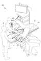
- the medical manipulator 1 according to the present embodimentis a treatment tool provided in the medical manipulator system 100 shown in FIG. 1 and inserted together with the endoscope 120 from the anus of the patient O lying on the operating table 110 into the body cavity. ..
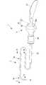
- the medical manipulator 1is connected to a soft and long soft shaft 3 and a base end of the soft shaft 3, and is manually operated by an operator P (base end). Part) 5 and. Further, as shown in FIGS. 3, 4 and 5, the medical manipulator 1 has a cable (electric cable) 7 for supplying electricity and a flexible shaft 3 for power associated with the operation performed on the operation unit 5. It is provided with a bending wire (wire) 9 that transmits to.
- the flexible shaft 3includes a tubular multi-lumen tube 11 having a plurality of lumens 19 and 21 into which a cable 7 and a bending wire 9 are inserted, and a multi-lumen tube 11 as shown in FIGS. 3, 4 and 5.
- Reinforcementconsisting of a tubular cover 13 that covers the circumference of the multi-lumen tube 11, a distal end 15 located at the tip of the multi-lumen tube 11, and a flexible tubular member that reinforces the connection between the distal end 15 and the multi-lumen tube 11. It includes a member 17.
- the distal end 15is provided with a high frequency knife (end effector) 16 for treating living tissue.
- the cable 7supplies the necessary electricity to the high frequency knife 16 according to the operation performed on the operation unit 5.
- the high-frequency knife 16can perform treatments such as excision of the affected area.
- the same effectcan be obtained by replacing the high-frequency knife 16 with the gripping forceps and the cable 7 with the opening / closing driving wire of the gripping forceps.
- the multi-lumen tube 11is arranged at the tip of the flexible elongated soft portion 11a and the tip of the soft portion 11a, and is curved in a direction intersecting the longitudinal axis A of the flexible portion 11a. It is provided with a possible curved portion 11b.
- the soft portion 11a and the curved portion 11bare joined by fusion with the tip of the soft portion 11a and the base end of the curved portion 11b connected in the longitudinal axis A direction.
- the base end portion of the soft portion 11ais pulled out from the base end portion of the cover 13 and arranged in the operation unit 5.
- the distal end 15is fixed to the tip of the curved portion 11b by fusion. Specifically, in a state where the periphery of the boundary between the tip end portion and the distal end portion 15 of the curved portion 11b is covered with the reinforcing member 17, the curved portion 11b, the distal end portion 15 and the reinforcing member 17 are fused. By being worn, the distal end portion 15 is joined to the tip end portion of the curved portion 11b.
- the reinforcing member 17allows the curved portion 11b and the distal end portion 15 to be more firmly joined to ensure stable strength. Therefore, the distal end portion 15 can be operated more sensitively to the movements of the soft portion 11a and the curved portion 11b.
- the flexible portion 11a and the curved portion 11bhave a first lumen 19 and a first lumen 19 penetrating the position including the central axis of the multi-lumen tube 11 in the longitudinal axis A direction.
- a plurality of, for example, eight second lumens 21 penetrating the outer side in the radial direction from the lumen 19 in the longitudinal axis A directionare provided.
- the first lumen 19 of the soft portion 11a and the first lumen 19 of the curved portion 11bform one continuous through hole, and each second lumen 21 of the soft portion 11a and each second lumen 21 of the curved portion 11b are also continuous. Each through hole is formed.
- the cable 7 of the high frequency knife 16is inserted in the first lumen 19. Further, in the first lumen 19, a reinforcing coil 23 made of a material harder than the flexible portion 11a and the curved portion 11b is housed in the entire area in the longitudinal direction.
- the tip of the cable 7is fixed to the distal end 15.
- the base end portion of the cable 7is fixed to the operation unit 5 in a state of being pulled out from the first lumen 19.
- the reinforcing coil 23is fixed to the distal end 15 by adhesion or abutment, and the other end in the longitudinal direction is fixed to the operation handle 27 described later in the operation unit 5 by caulking, adhesion or brazing. ing.
- a so-called round wire coil having a circular cross section or a flat wire coil having a rectangular cross sectionis used. It is preferable to use a flat wire coil in that the diameter of the multi-lumen tube 11 can be reduced as compared with the round wire coil.
- the reinforcing coil 23is arranged, for example, on the outer side in the radial direction of the cable 7 along the inner surface of the first lumen 19.
- the eight second lumens 21are arranged at substantially equal intervals in the circumferential direction around the longitudinal axis A of the multi-lumen tube 11.
- one bending wire 9is inserted into each of the four second lumens 21 corresponding to the upper, lower, left and right sides of the curved portion 11b.
- the vertical and horizontal directions of the curved portion 11bare orthogonal to the longitudinal axis A of the multi-lumen tube 11 and orthogonal to each other.
- Nothingis inserted in the remaining four second lumens 21 of the eight second lumens 21 and they are hollow.
- each bending wire 9At the tip of each bending wire 9, a sphere 9a having an outer diameter larger than the outer diameter of the cross section orthogonal to the longitudinal axis of each bending wire 9 is provided.
- the base end portion of each bending wire 9is fixed to the operation unit 5 in a state of being pulled out from the second lumen 21.
- Each bending wire 9can advance and retreat in the direction along the longitudinal axis A of the flexible portion 11a.
- the curved portion 11bis curved in the direction corresponding to the retracted bending wire 9.
- each second lumen 21is spirally formed around the longitudinal axis A.
- each second lumen 21 in the soft portion 11achanges along with the curvature of the soft portion 11a. Since each second lumen 21 in the soft portion 11a has a spiral shape, it is possible to prevent the contact state between the inner surface of each second lumen 21 and each bending wire 9 from being significantly changed depending on the bending state of the soft portion 11a. be able to.
- each of the spiral second lumens 21has a shape twisted at a constant pitch and a constant radius in one direction. Due to the spiral second lumen 21 having a uniform pitch, uniform performance can be exhibited in each part of the multi-lumen tube 11, and manufacturability can be improved.
- the cover 13includes a soft portion cover member 13a mainly arranged around the soft portion 11a and a curved portion cover member 13b mainly arranged around the curved portion 11b.
- the portion of the flexible shaft 3 composed of the soft portion 11a and the flexible portion cover member 13ais referred to as the shaft flexible portion 3a, and is composed of the curved portion 11b and the curved portion cover member 13b.
- the portionis referred to as a shaft curved portion 3b.
- the tip of the soft portion cover member 13ais fixed to the outer surface of the soft portion 11a, and the base end portion is fixed to the operation unit 5.
- the curved portion cover member 13bhas a tip end fixed to the distal end portion 15 and a base end portion fixed to the outer surface of the flexible portion 11a by adhesion.
- the flexible portion cover member 13a and the curved portion cover member 13bare fused with each other, that is, the tip surface of the flexible portion cover member 13a and the base end surface of the curved portion cover member 13b are connected in the longitudinal axis A direction. It is integrally composed of clothes.
- the curved portion cover member 13bis made of a material softer than the soft portion cover member 13a.
- the curved portion cover member 13bis fixed to the side surface of the tip end portion of the rotational force transmission coil 33, which will be described later, by adhesion or fusion. Further, it is desirable that both the soft portion cover member 13a and the curved portion cover member 13b are made of an insulating material.
- As the material of the flexible portion cover member 13afor example, low-density polyethylene is used, and as the material of the curved portion cover member 13b, for example, a styrene-based elastomer is used.
- the shaft curved portion 3bcan be curved more smoothly. Further, since both the soft portion cover member 13a and the curved portion cover member 13b are insulating, when the high frequency knife 16 is adopted as the end effector, the high frequency of the high frequency knife 16 energizes the medical manipulator 1 or causes the medical manipulator 1 to be energized. It is possible to prevent leakage to the outside of the medical manipulator 1.
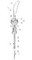
- the operation unit 5has a rigid rotary shaft 25 extending coaxially with the flexible shaft 3 and an operation handle arranged on the proximal end side of the rotary shaft 25 and gripped by the operator P. 27, a rotation operation unit 29 fixed to the base end of the rotation shaft 25 and for rotating the flexible shaft 3 and the rotation shaft 25, and arranged between the rotation operation unit 29 and the operation handle 27, the multi-lumen tube 11 A bending operation portion 31 for bending the bending portion 11b of the above, and a rotational force transmission coil 33 (see FIGS. 3 and 5) for transmitting a rotational force to the flexible shaft 3 are provided.
- the rotating shaft 25has a shaft through hole 25a that penetrates along the longitudinal axis A.
- the base end portion of the flexible portion cover member 13ais fixed to the tip end portion of the shaft through hole 25a. Further, the soft portion 11a of the multi-lumen tube 11 pulled out from the base end of the flexible portion cover member 13a penetrates through the shaft through hole 25a.
- the curved operation unit 31has a ball joint structure including a substantially spherical hollow socket 35 and a substantially spherical hollow ball 37 rotatably engaged in the socket 35.
- the socket 35is connected to the base end of the rotating shaft 25.
- the socket 35has a shape in which a portion on the base end side of the sphere is cut out in a plane orthogonal to the longitudinal axis A of the rotating shaft 25.
- the notched base end surface of the socket 35is open.
- the notched base end surface of the socket 35is defined as the opening 35a.
- the socket 35is formed in a spherical shape larger than a hemisphere. As a result, the ball 37 is held in the socket 35 without coming out of the opening 35a of the socket 35.
- the ball 37is supported by the inner surface of the socket 35 at a position where the center point of the ball 37 coincides with the center point of the socket 35. As a result, the ball 37 can rotate in any direction around the center point with respect to the socket 35.
- the operation handle 27is connected to the outer surface of the ball 37 exposed to the outside from the opening 35a of the socket 35, and extends to the side opposite to the rotating shaft 25 and the socket 35.
- the operation handle 27is aligned with the rotating shaft 25 in the neutral position. Further, the operation handle 27 is tilted in an arbitrary direction around the center point of the socket 35 and the ball 37 by the rotation of the ball 37 in the socket 35.
- the base end of the flexible portion 11a of the multi-lumen tube 11 penetrating the shaft through hole 25ais fixed to the tip end portion of the operation handle 27.
- the cable 7 pulled out from the first lumen 19 of the flexible portion 11ais connected to the operation handle 27.
- an electric currentflows through the cable 7 by inputting a button or the like provided on the operation handle 27, and energizes the high-frequency knife.
- the four bending wires 9 drawn from the second lumen 21 of the flexible portion 11aare arranged between the inner surface of the socket 35 and the outer surface of the ball 37.
- Each base end of the four bending wires 9is fixed at a position equally spaced in the circumferential direction around the longitudinal axis A on the outer surface of the ball 37 with the operation handle 27 arranged in the neutral position. ..
- the left bending wire 9is pulled by the right rotation of the ball 37 and the right bending wire 9 is pushed out, so that the multi-lumen tube 11 is bent.
- the portion 11bcurves to the left.
- the right bending wire 9is pulled by the left rotation of the ball 37 and the left bending wire 9 is pushed out, so that the bending portion 11b is bent to the right. ..
- the vertical angle of the bending portion 11bdoes not change.
- the rotation operation unit 29is a rotation handle arranged coaxially with the rotation shaft 25.
- the rotation operation unit 29is provided with a lock mechanism (not shown) for locking the rotation of the rotation operation unit 29 with respect to the bending operation unit 31 and the operation handle 27.
- the rotational force transmission coil 33is composed of, for example, three layers of coils arranged in a stacked state in the radial direction. As shown in FIG. 5, for example, the rotational force transmission coil 33 is arranged along the longitudinal axis A between the soft portion 11a of the multi-lumen tube 11 and the soft portion cover member 13a. One end of the rotational force transmission coil 33 in the longitudinal direction is fixed to the tip of the flexible portion 11a, and the other end in the longitudinal direction is fixed to the rotary shaft 25.
- the flexible shaftis passed through the channel of the endoscope 120 or the channel external to the endoscope 120. Insert 3 into the body. Then, the flexible shaft 3 is arranged at a position where the tip end portion of the flexible shaft 3 is observed in the endoscopic image.
- the operator Protates the flexible shaft 3 around the longitudinal axis A by the rotation operation of the rotation operation unit 29. Further, the operator P bends the shaft bending portion 3b in an arbitrary direction intersecting the longitudinal axis A by tilting the operation handle 27.
- the bending wires 9 corresponding to the tilting direction of the operating handle 27are pushed and pulled in each of the second lumens 21 to cause stress such as friction on each of the second lumens 21. It takes.
- the second lumen 21is spirally formed in the soft portion 11a of the multi-lumen tube 11, the second lumen 21 is moved to each second lumen 21 as compared with the case where the second lumen 21 is not spirally formed. Stress such as friction increases.
- the entire length of the first lumen 19 penetrating both the soft portion 11a and the curved portion 11b of the multi-lumen tube 11, both ends in the longitudinal directionare distal ends 15 and the operation unit 5
- a reinforcing coil 23which is fixed to and is made of a material harder than the flexible portion 11a and the curved portion 11b is arranged.
- the reinforcing coil 23causes deformation due to compression in both the soft portion 11a and the bending portion 11b. Can be prevented. As a result, the operability of the curved portion 11b is improved, and the shaft curved portion 3b can be curved into a desired shape.
- the effect of the reinforcing coil 23will be described with reference to FIG.
- the reinforcing coil 23is arranged over the entire length of the multi-lumen tube 11, even if the bending wire 9 is pulled, compression deformation does not occur in either the flexible portion 11a or the bending portion 11b, and the bending wire 9 is pulled.
- the curved portion 11bis well curved.
- the traction amount of the bending wire 9, that is, the distance interval for traction of the bending wire 9can be small, and the tube 11 can be easily inserted into the endoscopic channel.
- the reinforcing coil 23When the reinforcing coil 23 is provided only in the soft portion 11a, compression deformation does not occur in the soft portion 11a even if the bending wire 9 is pulled. Therefore, the traction amount of the bending wire 9 is smaller than that in the case where the reinforcing coil 23 is not provided, and it is easy to insert it into the endoscope channel. However, the curved portion 11b is not curved and compression deformation occurs.
- the rotational force transmission coil 33is arranged between the soft portion 11a and the soft portion cover member 13a.
- a rotational force transmission coil 33may be provided for each second lumen 21, but by arranging the rotational force transmission coil 33 between the soft portion 11a and the soft portion cover member 13a, the entire multi-lumen tube 11 is lengthened. It can be easily rotated around the axis A.
- the second lumen 21 of the soft portion 11ahas a spiral shape.
- the second lumen 21 of the flexible portion 11ais parallel to each other along the longitudinal direction at positions at equal intervals in the circumferential direction around the longitudinal axis A, similarly to the second lumen 21 of the curved portion 11b. It may be arranged.
Landscapes
- Health & Medical Sciences (AREA)
- Engineering & Computer Science (AREA)
- Surgery (AREA)
- Life Sciences & Earth Sciences (AREA)
- Animal Behavior & Ethology (AREA)
- General Health & Medical Sciences (AREA)
- Biomedical Technology (AREA)
- Heart & Thoracic Surgery (AREA)
- Medical Informatics (AREA)
- Molecular Biology (AREA)
- Nuclear Medicine, Radiotherapy & Molecular Imaging (AREA)
- Robotics (AREA)
- Public Health (AREA)
- Veterinary Medicine (AREA)
- Cardiology (AREA)
- Physics & Mathematics (AREA)
- Plasma & Fusion (AREA)
- Otolaryngology (AREA)
- Surgical Instruments (AREA)
- Endoscopes (AREA)
Abstract
Description
Translated fromJapanese本発明は、医療用マニピュレータに関するものである。The present invention relates to a medical manipulator.
従来、湾曲部と、湾曲部を湾曲させる複数のワイヤが貫通するマルチルーメンが内部に設けられた軟性部とを有する挿入部を備える医療用マニピュレータが知られている(例えば、特許文献1,2参照。)。医療用マニピュレータにおいては、各ワイヤを牽引すると、マルチルーメンに摩擦等のストレスがかかることによって、マルチルーメンに圧縮による変形が生じる。そのため、湾曲部が所望の湾曲形状とならず、湾曲部の操作性に影響をきたす。Conventionally, a medical manipulator having an insertion portion having a curved portion and a flexible portion provided with a multi-lumen through which a plurality of wires for bending the curved portion penetrate is known (for example,
特許文献1,2に記載の医療用マニピュレータは、柔軟性を有し湾曲可能だがその長手方向には実質的に収縮しない特性を有するコイルシースを、補強部材として軟性部の各ルーメンにそれぞれ収納することにより、マルチルーメンの収縮を防止している。In the medical manipulators described in
しかしながら、特許文献1,2に記載の医療用マニピュレータには、各ワイヤを牽引すると、湾曲部に圧縮による変形が生じるのを防ぐことができず、湾曲部の操作性を改善することができないという不都合がある。However, in the medical manipulators described in
本発明は、上述した事情に鑑みてなされたものであって、ワイヤを牽引した場合において、湾曲部に圧縮による変形が生じるのを防ぎ、湾曲部の操作性を向上することができる医療用マニピュレータを提供することを目的としている。The present invention has been made in view of the above circumstances, and is a medical manipulator capable of preventing deformation of the curved portion due to compression when the wire is towed and improving the operability of the curved portion. Is intended to provide.
上記目的を達成するため、本発明は以下の手段を提供する。
本発明の一態様は、可撓性を有する細長い軟性部と、該軟性部の先端に配置された湾曲可能な湾曲部とを備えるマルチルーメンチューブと、前記湾曲部の先端に配置された遠位端部と、前記軟性部の基端に配置された基端部と、前記基端部からの動力を前記湾曲部に伝達することによって該湾曲部を湾曲させる複数のワイヤと、前記軟性部および前記湾曲部よりも硬質の素材からなり、長手方向の一端が前記遠位端部に固定され、長手方向の他端が前記基端部に固定される補強コイルとを備え、前記軟性部および前記湾曲部が、前記マルチルーメンチューブの中心軸を含む位置を長手方向に貫通し前記補強コイルが挿入される第1ルーメンと、該第1ルーメンよりも外側を前記長手方向に貫通し複数の前記ワイヤが挿入される複数の第2ルーメンとを備える医療用マニピュレータである。In order to achieve the above object, the present invention provides the following means.
One aspect of the invention is a multi-lumen tube comprising a flexible elongated soft portion, a bendable bend located at the tip of the soft portion, and a distal portion located at the tip of the bend. An end portion, a base end portion arranged at the base end of the soft portion, a plurality of wires for bending the curved portion by transmitting power from the base end portion to the curved portion, the soft portion, and the flexible portion. It is made of a material harder than the curved portion, includes a reinforcing coil having one end in the longitudinal direction fixed to the distal end portion and the other end in the longitudinal direction fixed to the proximal end portion, the soft portion and the soft portion. A first lumen in which the curved portion penetrates the position including the central axis of the multi-lumen tube in the longitudinal direction and the reinforcing coil is inserted, and a plurality of the wires penetrating the outside of the first lumen in the longitudinal direction. Is a medical manipulator with a plurality of second lumens into which the is inserted.
本態様によれば、マルチルーメンチューブを構成する軟性部および湾曲部の第2ルーメンを貫通している複数のワイヤによって、基端部からの動力が湾曲部に伝達されることにより、湾曲部が湾曲させられる。According to this aspect, the curved portion is formed by transmitting the power from the proximal end portion to the curved portion by a plurality of wires penetrating the soft portion and the second lumen of the curved portion constituting the multi-lumen tube. Be curved.
軟性部および湾曲部には、マルチルーメンチューブの中心軸を含む位置に形成された第1ルーメンに、長手方向の両端が遠位端部と基端部とに固定され、かつ、軟性部および湾曲部よりも硬質の素材からなる補強コイルが配置されている。したがって、各ワイヤを牽引することによって各第2ルーメンに摩擦等のストレスがかかったとしても、補強コイルにより、軟性部および湾曲部の両方において圧縮による変形が生じるのを防ぐことができる。これにより、湾曲部の操作性が向上し、湾曲部を所望の形状に湾曲させることができる。In the soft portion and the curved portion, both ends in the longitudinal direction are fixed to the distal end portion and the proximal end portion in a first lumen formed at a position including the central axis of the multi-lumen tube, and the soft portion and the curved portion are formed. A reinforcing coil made of a material harder than the part is arranged. Therefore, even if stress such as friction is applied to each second lumen by pulling each wire, the reinforcing coil can prevent deformation due to compression in both the soft portion and the curved portion. As a result, the operability of the curved portion is improved, and the curved portion can be curved into a desired shape.
上記態様に係る医療用マニピュレータは、前記軟性部を貫通する複数の前記第2ルーメンが、前記軟性部の長手軸回りに螺旋状に形成されていることとしてもよい。In the medical manipulator according to the above aspect, a plurality of the second lumens penetrating the soft portion may be spirally formed around the longitudinal axis of the soft portion.
マルチルーメンチューブが挿入される生体の管腔内の形状に応じて、可撓性を有する軟性部が湾曲することにより、軟性部の湾曲とともに軟性部の複数の第2ルーメンの形状も変化する。軟性部の各第2ルーメンが軟性部の長手軸回りに螺旋形状を有することにより、各第2ルーメンの内面と各第2ルーメン内の各ワイヤとの接触状態が軟性部の湾曲状態によっては大きく変化せず、各ワイヤに経路差が生じるのを抑制することができる。これにより、軟性部の湾曲状態に応じて、基端部からの動力をワイヤ間で大きく異ならせる必要がない。よって、湾曲部の操作性および制御性を向上することができる。By bending the flexible soft portion according to the shape in the lumen of the living body into which the multi-lumen tube is inserted, the shape of the plurality of second lumens of the soft portion changes along with the curvature of the soft portion. Since each second lumen of the soft portion has a spiral shape around the longitudinal axis of the soft portion, the contact state between the inner surface of each second lumen and each wire in each second lumen is large depending on the curved state of the soft portion. It does not change, and it is possible to suppress the occurrence of a path difference in each wire. As a result, it is not necessary to make the power from the proximal end portion significantly different between the wires depending on the curved state of the soft portion. Therefore, the operability and controllability of the curved portion can be improved.
上記態様に係る医療用マニピュレータは、前記マルチルーメンチューブの周囲を覆うカバーを備え、該カバーが、前記軟性部の周囲に配置される軟性部カバー部材と、該軟性部カバー部材よりも軟質の素材からなり、前記湾曲部の周囲に配置される湾曲部カバー部材とを備えることとしてもよい。The medical manipulator according to the above aspect includes a cover that covers the periphery of the multi-lumen tube, and the cover is a soft portion cover member arranged around the soft portion and a material that is softer than the soft portion cover member. It may be provided with a curved portion cover member which is composed of the curved portion and is arranged around the curved portion.
カバーによって、マルチルーメンチューブを保護することができる。この場合において、湾曲部カバー部材が軟性部カバー部材よりも軟質の素材からなることによって、マルチルーメンチューブの湾曲部をよりスムーズに湾曲させることができる。The cover can protect the multi-lumen tube. In this case, since the curved portion cover member is made of a material softer than the soft portion cover member, the curved portion of the multi-lumen tube can be curved more smoothly.
上記態様に係る医療用マニピュレータは、前記軟性部カバー部材および前記湾曲部カバー部材が絶縁性材料によって構成されていることとしてもよい。
この構成によって、遠位端部として高周波ナイフを採用する場合において、絶縁性材料によって構成された軟性部カバー部材および湾曲部カバー部材により、高周波ナイフの高周波がマニピュレータに通電したり、マニピュレータの外部に漏れたりしてしまうのを防ぐことができる。In the medical manipulator according to the above aspect, the flexible portion cover member and the curved portion cover member may be made of an insulating material.
With this configuration, when a high frequency knife is used as the distal end, the high frequency of the high frequency knife can be applied to the manipulator or to the outside of the manipulator by the soft part cover member and the curved part cover member made of the insulating material. It is possible to prevent leakage.
上記態様に係る医療用マニピュレータは、前記軟性部の長手方向に沿って延び、前記基端部からの前記軟性部の長手軸回りの回転力を前記軟性部に伝達する回転力伝達コイルを備え、該回転力伝達コイルが、前記軟性部と前記軟性部カバー部材との間に配置され、長手方向の一端が前記軟性部の先端に固定され、長手方向の他端が前記基端部に固定されていることとしてもよい。The medical manipulator according to the above aspect includes a rotational force transmission coil that extends along the longitudinal direction of the soft portion and transmits a rotational force around the longitudinal axis of the soft portion from the base end portion to the soft portion. The rotational force transmission coil is arranged between the soft portion and the soft portion cover member, one end in the longitudinal direction is fixed to the tip of the soft portion, and the other end in the longitudinal direction is fixed to the base end portion. It may be that it is.
回転力伝達コイルによって、基端部からの軟性部の長手軸回りの回転力が軟性部に伝達されることにより、マルチルーメンチューブ全体が長手軸回りに回転させられる。
この場合において、回転力伝達コイルを軟性部と軟性部カバー部材との間に配置することにより、第2ルーメンごとに回転力伝達コイルを設ける場合と比較して、マルチルーメンチューブ全体を長手軸回りに容易に回転させることができる。The rotational force transmission coil transmits the rotational force around the longitudinal axis of the soft portion from the base end portion to the flexible portion, so that the entire multi-lumen tube is rotated around the longitudinal axis.
In this case, by arranging the rotational force transmission coil between the soft portion and the soft portion cover member, the entire multi-lumen tube is rotated around the longitudinal axis as compared with the case where the rotational force transmission coil is provided for each second lumen. Can be easily rotated.
上記態様に係る医療用マニピュレータは、前記湾曲部と前記遠位端部との境界の周囲を被覆する補強部材を備えることとしてもよい。
補強部材により、湾曲部と遠位端部とがより強固に接続される。したがって、軟性部および湾曲部の動作に対して遠位端部をより感度よく動作させることができる。The medical manipulator according to the above aspect may include a reinforcing member that covers the periphery of the boundary between the curved portion and the distal end portion.
Reinforcing members provide a tighter connection between the bend and the distal end. Therefore, the distal end can be moved more sensitively to the movement of the soft and curved parts.
本発明によれば、ワイヤを牽引した場合において、湾曲部に圧縮による変形が生じるのを防ぎ、湾曲部の操作性を向上することができるという効果を奏する。According to the present invention, when the wire is towed, it is possible to prevent the curved portion from being deformed by compression and to improve the operability of the curved portion.
本発明の一実施形態に係る医療用マニピュレータについて図面を参照して以下に説明する。
本実施形態に係る医療用マニピュレータ1は、図1に示される医療用マニピュレータシステム100に備えられ、手術台110に横たわる患者Oの肛門から体腔内に内視鏡120とともに挿入される処置具である。The medical manipulator according to the embodiment of the present invention will be described below with reference to the drawings.
The
医療用マニピュレータ1は、図1および図2に示されるように、軟性かつ長尺の軟性シャフト3と、軟性シャフト3の基端に接続され、操作者Pによって手動操作される操作ユニット(基端部)5とを備えている。また、医療用マニピュレータ1は、図3、図4および図5に示されるように、電気を供給するためのケーブル(電気ケーブル)7と、操作ユニット5になされた操作に伴う動力を軟性シャフト3に伝達する湾曲用ワイヤ(ワイヤ)9とを備えている。As shown in FIGS. 1 and 2, the
軟性シャフト3は、図3、図4および図5に示されるように、ケーブル7および湾曲用ワイヤ9が挿入される複数のルーメン19,21を有する管状のマルチルーメンチューブ11と、マルチルーメンチューブ11の周囲を覆う管状のカバー13と、マルチルーメンチューブ11の先端に配置された遠位端部15と、遠位端部15とマルチルーメンチューブ11との接続を補強する軟性の管状部材からなる補強部材17とを備えている。The
遠位端部15には、生体組織を処置するための高周波ナイフ(エンドエフェクタ)16が設けられている。ケーブル7は、操作ユニット5になされた操作に応じて高周波ナイフ16に必要な電気を供給する。そのことによって、高周波ナイフ16は患部の切除等の処置を実施することができる。なお、当該実施例以外に、高周波ナイフ16を把持鉗子、ケーブル7を把持鉗子の開閉駆動用ワイヤに置き換えた構成でも、同様の効果を奏し得る。The
マルチルーメンチューブ11は、図5および図6に示されるように、可撓性を有する細長い軟性部11aと、軟性部11aの先端に配置され、軟性部11aの長手軸Aに交差する方向に湾曲可能な湾曲部11bとを備えている。As shown in FIGS. 5 and 6, the
軟性部11aと湾曲部11bは、軟性部11aの先端と湾曲部11bの基端とが長手軸A方向に連結された状態で融着によって接合されている。
軟性部11aの基端部は、カバー13の基端から引き出されて操作ユニット5内に配置されている。The
The base end portion of the
湾曲部11bの先端部には、融着によって遠位端部15が固定されている。具体的には、湾曲部11bの先端部と遠位端部15との境界の周囲が補強部材17によって被覆された状態で、これら湾曲部11bおよび遠位端部15と補強部材17とが融着されることによって、湾曲部11bの先端部に遠位端部15が接合されている。補強部材17により、湾曲部11bと遠位端部15とがより強固に接合され、安定した強度を確保することができる。したがって、軟性部11aおよび湾曲部11bの動作に対して遠位端部15をより感度よく動作させることができる。The
軟性部11aおよび湾曲部11bには、図3、図4および図5に示されるように、マルチルーメンチューブ11の中心軸を含む位置を長手軸A方向に貫通する第1ルーメン19と、第1ルーメン19よりも径方向の外側を長手軸A方向に貫通する複数、例えば8つの第2ルーメン21とが設けられている。軟性部11aの第1ルーメン19と湾曲部11bの第1ルーメン19は連続する1つの貫通孔を形成し、軟性部11aの各第2ルーメン21と湾曲部11bの各第2ルーメン21もそれぞれ連続する各貫通孔を形成している。As shown in FIGS. 3, 4 and 5, the
第1ルーメン19には、高周波ナイフ16のケーブル7が挿入されている。また、第1ルーメン19には、軟性部11aおよび湾曲部11bよりも硬質の素材からなる補強コイル23が長手方向の全域に収納されている。The
ケーブル7の先端部は遠位端部15に固定されている。ケーブル7の基端部は、第1ルーメン19から引き出された状態で操作ユニット5に固定されている。The tip of the
補強コイル23は、長手方向の一端が遠位端部15に接着または突き当てによって固定され、長手方向の他端が操作ユニット5内において後述する操作ハンドル27にカシメ、接着またはロウ付けによって固定されている。補強コイル23としては、断面が円形状のいわゆる丸線コイル、または、断面が矩形状の平線コイルが用いられる。丸線コイルと比較してマルチルーメンチューブ11の細径化を図ることができるという点で、平線コイルを採用するのが好ましい。補強コイル23は、例えば、ケーブル7よりも径方向の外側を第1ルーメン19の内面に沿って配されている。One end of the reinforcing
8つの第2ルーメン21は、マルチルーメンチューブ11の長手軸A回りの周方向に略等間隔をあけて配置されている。8つの第2ルーメン21の内、湾曲部11bの上、下、左および右にそれぞれ対応する4つの第2ルーメン21には、それぞれ湾曲用ワイヤ9が1本ずつ挿入されている。湾曲部11bの上下方向および左右方向は、マルチルーメンチューブ11の長手軸Aにそれぞれ直交し、かつ、互いに直交する方向である。8つの第2ルーメン21の内の残りの4つの第2ルーメン21には何も挿入されておらず、空洞である。The eight
各湾曲用ワイヤ9の先端には、各湾曲用ワイヤ9の長手軸に直交する断面の外径よりも大きい外径の球9aが設けられている。各球9aが遠位端部15に埋設されることによって、各湾曲用ワイヤ9の先端部が遠位端部15に固定されている。各湾曲用ワイヤ9の基端部は、それぞれ第2ルーメン21から引き出された状態で操作ユニット5に固定されている。各湾曲用ワイヤ9は、軟性部11aの長手軸Aに沿う方向に進退可能である。湾曲用ワイヤ9を基端側に後退させると、後退させた湾曲用ワイヤ9と対応する方向に湾曲部11bが湾曲する。At the tip of each
湾曲部11bにおいては、図6に示されるように、各第2ルーメン21が、長手軸A回りの周方向に略等間隔をあけた位置において、長手方向に沿って互いに平行に形成されている。一方、軟性部11aにおいては、図6に示されるように、各第2ルーメン21が長手軸A回りに螺旋状に形成されている。In the
軟性部11aが湾曲すると、軟性部11aの湾曲とともに軟性部11a内の各第2ルーメン21の形状も変化する。軟性部11a内の各第2ルーメン21が螺旋形状を有することにより、各第2ルーメン21の内面と各湾曲用ワイヤ9との接触状態が軟性部11aの湾曲状態によって大きく変化するのを抑制することができる。When the
これにより、大腸等の管腔内に医療用マニピュレータ1を挿入した場合に生じる各湾曲用ワイヤ9間の経路差を解消することができる。したがって、軟性部11aの湾曲状態に応じて、操作ユニット5からの動力を各湾曲用ワイヤ9間で大きく異ならせる必要がなく、湾曲部11bの操作性および制御性を向上することができる。As a result, it is possible to eliminate the path difference between the bending
螺旋状の各第2ルーメン21は、一方向に一定のピッチおよび一定の半径で捻られた形状であることが好ましい。均一なピッチの螺旋状の第2ルーメン21によって、マルチルーメンチューブ11の各部において均一な性能を発揮することができるとともに、製造容易性を向上することができる。It is preferable that each of the spiral
カバー13は、図5に示されるように、主に軟性部11aの周囲に配置される軟性部カバー部材13aと、主に湾曲部11bの周囲に配置される湾曲部カバー部材13bとを備えている。以下、図5に示されるように、軟性シャフト3のうち、軟性部11aおよび軟性部カバー部材13aによって構成される部分をシャフト軟性部3aとし、湾曲部11bおよび湾曲部カバー部材13bによって構成される部分をシャフト湾曲部3bとする。As shown in FIG. 5, the
軟性部カバー部材13aは、先端部が軟性部11aの外面に固定され、基端部が操作ユニット5に固定されている。湾曲部カバー部材13bは、先端部が遠位端部15に固定され、基端部が軟性部11aの外面に接着によって固定されている。軟性部カバー部材13aと湾曲部カバー部材13bは、それぞれの端面どうし、すなわち、軟性部カバー部材13aの先端面と湾曲部カバー部材13bの基端面とが長手軸A方向に連結された状態で融着によって一体的に構成されている。The tip of the soft
湾曲部カバー部材13bは、軟性部カバー部材13aよりも軟質の素材によって形成されている。湾曲部カバー部材13bは、後述する回転力伝達コイル33の先端部の側面に接着または融着によって固定されている。また、軟性部カバー部材13aおよび湾曲部カバー部材13bは、いずれも絶縁性材料によって構成されていることが望ましい。軟性部カバー部材13aの材料としては、例えば、低密度ポリエチレンが用いられ、湾曲部カバー部材13bの材料としては、例えば、スチレン系エラストマーが用いられる。The curved
湾曲部カバー部材13bが軟性部カバー部材13aよりも軟質であることにより、シャフト湾曲部3bをよりスムーズに湾曲させることができる。また、軟性部カバー部材13aおよび湾曲部カバー部材13bの両方が絶縁性であることにより、エンドエフェクタとして高周波ナイフ16を採用した場合において、高周波ナイフ16の高周波が医療用マニピュレータ1に通電したり、医療用マニピュレータ1の外部に漏れたりしてしまうのを防ぐことができる。Since the curved
操作ユニット5は、図2および図7に示されるように、軟性シャフト3と同軸に延びる硬質の回転シャフト25と、回転シャフト25の基端側に配置され、操作者Pに把持される操作ハンドル27と、回転シャフト25の基端に固定され、軟性シャフト3および回転シャフト25を回転させるための回転操作部29と、回転操作部29と操作ハンドル27との間に配置され、マルチルーメンチューブ11の湾曲部11bを湾曲させるための湾曲操作部31と、軟性シャフト3に回転力を伝達する回転力伝達コイル33(図3および図5参照。)とを備えている。As shown in FIGS. 2 and 7, the
回転シャフト25は、長手軸Aに沿って貫通するシャフト貫通孔25aを有している。シャフト貫通孔25aの先端部には軟性部カバー部材13aの基端部が固定されている。また、シャフト貫通孔25aには、軟性部カバー部材13aの基端から引き出されたマルチルーメンチューブ11の軟性部11aが貫通している。The rotating
湾曲操作部31は、略球状の中空のソケット35と、ソケット35内に回転可能に係合された略球状の中空のボール37とを備えるボールジョイント構造を有している。The
ソケット35は、回転シャフト25の基端に接続されている。ソケット35は、球体の基端側の部分を回転シャフト25の長手軸Aに直交する平面で切り欠いた形状を有している。ソケット35の切り欠かれた基端面は開口している。ソケット35の切り欠かれた基端面を開口35aとする。ソケット35は半球よりも大きい球状に形成されている。これにより、ボール37がソケット35の開口35aから抜けることなくソケット35内に保持される。The
ボール37は、ボール37の中心点がソケット35の中心点と一致する位置において、ソケット35の内面によって支持されている。これにより、ボール37は、ソケット35に対して中心点回りの任意の方向に回転可能である。The
操作ハンドル27は、ソケット35の開口35aから外側に露出するボール37の外面に接続され、回転シャフト25およびソケット35とは反対側へ延びている。The operation handle 27 is connected to the outer surface of the
操作ハンドル27は、図7に示さるように、中立位置において回転シャフト25と一直線に並ぶ。また、操作ハンドル27は、ソケット35内でのボール37の回転によって、ソケット35およびボール37の中心点回りの任意の方向に傾倒する。As shown in FIG. 7, the operation handle 27 is aligned with the rotating
ソケット35内においては、シャフト貫通孔25aを貫通したマルチルーメンチューブ11の軟性部11aの基端が操作ハンドル27の先端部に固定されている。軟性部11aの第1ルーメン19から引き出されたケーブル7は操作ハンドル27に接続されている。例えば、操作ハンドル27に備わるボタン等の入力によって、ケーブル7に電流が流れ、高周波ナイフに通電する。In the
また、軟性部11aの第2ルーメン21から引き出された4本の湾曲用ワイヤ9は、ソケット35の内面とボール37の外面との間に配されている。4本の湾曲用ワイヤ9の各基端は、操作ハンドル27が中立位置に配置された状態で、ボール37の外面における長手軸A回りの周方向に等間隔をあけた位置に固定されている。Further, the four
例えば、操作ハンドル27を右方向に傾倒させると、ボール37の右方向の回転によって左の湾曲用ワイヤ9が牽引されるとともに右の湾曲用ワイヤ9が押し出されることにより、マルチルーメンチューブ11の湾曲部11bが左へ湾曲する。操作ハンドル27を左方向に傾倒させると、ボール37の左方向の回転によって右の湾曲用ワイヤ9が牽引されるとともに左の湾曲用ワイヤ9が押し出されることにより、湾曲部11bが右へ湾曲する。このときに、上および下の湾曲用ワイヤ9は、ボール37によって牽引および押圧されないので、湾曲部11bの上下方向の角度は変化しない。For example, when the operation handle 27 is tilted to the right, the
操作ハンドル27を上方向に傾倒させると、ボール37の上方向の回転によって下の湾曲用ワイヤ9が牽引されるとともに上の湾曲用ワイヤ9が押し出されることにより、湾曲部11bが下へ湾曲する。操作ハンドル27を下方向に傾倒させると、ボール37の下方向の回転によって上の湾曲用ワイヤ9が牽引されるとともに下の湾曲用ワイヤ9が押し出されることにより、湾曲部11bが上へ湾曲する。このときに、左および右の湾曲用ワイヤ9は、ボール37によって牽引および押圧されないので、湾曲部11bの左右方向の角度は変化しない。When the operation handle 27 is tilted upward, the
回転操作部29は、回転シャフト25と同軸に配置された回転ハンドルである。回転操作部29には、湾曲操作部31および操作ハンドル27に対する回転操作部29の回転をロックするためのロック機構(図示略)が設けられている。The
回転力伝達コイル33は、例えば、径方向に積層状態に配された3層のコイルによって構成されている。回転力伝達コイル33は、例えば、図5に示されるように、マルチルーメンチューブ11の軟性部11aと軟性部カバー部材13aとの間に長手軸Aに沿って配されている。回転力伝達コイル33は、長手方向の一端が軟性部11aの先端に固定され、長手方向の他端が回転シャフト25に固定されている。The rotational
回転操作部29を長手軸A回りに回転させると、軟性シャフト3および回転シャフト25が長手軸A回りに回転する。すなわち、回転操作部29の回転によって、回転シャフト25が湾曲操作部31および操作ハンドル27に対して長手軸A回りに回転する。回転シャフト25が回転すると、回転シャフト25と接続されている軟性部カバー部材13aの基端部に長手軸A回りの回転力が伝達されるとともに、回転シャフト25に接続されている回転力伝達コイル33によって、長手軸A回りの回転力が軟性部11aの先端部に伝達される。これにより、湾曲部11bを含む軟性シャフト3の全体が、回転操作部29および回転シャフト25とともに長手軸A回りに回転する。When the
次に、上記構成の医療用マニピュレータ1の作用について説明する。
本実施形態に係る医療用マニピュレータ1を使用して患者Oの体内の生体組織を処置するためには、内視鏡120のチャネルまたは内視鏡120に外付けされたチャネルを経由させて軟性シャフト3を体内に挿入する。そして、軟性シャフト3の先端部が内視鏡画像内で観察される位置に軟性シャフト3を配置する。Next, the operation of the
In order to treat the living tissue in the body of the patient O using the
操作者Pは、回転操作部29の回転操作によって、軟性シャフト3を長手軸A回りに回転させる。また、操作者Pは、操作ハンドル27の傾倒操作によってシャフト湾曲部3bを長手軸Aに交差する任意の方向に湾曲させる。The operator P rotates the
ここで、操作ハンドル27の傾倒操作に従い、操作ハンドル27の傾倒方向に対応する各湾曲用ワイヤ9が各第2ルーメン21内で押し引きされることにより、各第2ルーメン21に摩擦等のストレスがかかる。特に、マルチルーメンチューブ11の軟性部11aにおいて第2ルーメン21が螺旋状に形成されていることによって、第2ルーメン21が螺旋状に形成されていない場合と比較して、各第2ルーメン21への摩擦等のストレスが大きくなる。Here, according to the tilting operation of the
本実施形態に係る医療用マニピュレータ1は、マルチルーメンチューブ11の軟性部11aおよび湾曲部11bの両方を貫通する第1ルーメン19の全長に、長手方向の両端が遠位端部15と操作ユニット5とに固定され、かつ、軟性部11aおよび湾曲部11bよりも硬質の素材からなる補強コイル23が配置されている。In the
したがって、各湾曲用ワイヤ9を牽引することによって各第2ルーメン21に摩擦等のストレスがかかったとしても、補強コイル23により、軟性部11aおよび湾曲部11bの両方において圧縮による変形が生じるのを防ぐことができる。これにより、湾曲部11bの操作性が向上し、シャフト湾曲部3bを所望の形状に湾曲させることができる。Therefore, even if stress such as friction is applied to each
例えば、図8を参照して、補強コイル23による効果を説明する。補強コイル23をマルチルーメンチューブ11の全長に配置した場合は、湾曲用ワイヤ9を牽引しても、軟性部11aおよび湾曲部11bのいずれにおいても圧縮変形は生じず、湾曲用ワイヤ9の牽引によって湾曲部11bが良好に湾曲する。この場合は、マルチルーメンチューブ11が圧縮変形しないため、湾曲用ワイヤ9の牽引量すなわち湾曲用ワイヤ9を牽引する距離間隔が小さくて済むとともに、内視鏡チャネルへも挿入し易い。For example, the effect of the reinforcing
これに対し、比較例として、マルチルーメンチューブ11のいずれにも補強コイル23を設けない場合は、湾曲用ワイヤ9を牽引すると、湾曲部11bが湾曲せずに、軟性部11aおよび湾曲部11bの両方において圧縮変形が生じる。この場合は、湾曲用ワイヤ9を牽引すればするほどマルチルーメンチューブ11が圧縮変形するため、湾曲用ワイヤ9の牽引量が大きくなる。また、マルチルーメンチューブ11が圧縮変形し易いことから、内視鏡チャネルへも挿入し難い。On the other hand, as a comparative example, when the reinforcing
なお、軟性部11aのみに補強コイル23を設けた場合は、湾曲用ワイヤ9を牽引しても軟性部11aに圧縮変形は生じない。そのため、補強コイル23を設けない場合よりは、湾曲用ワイヤ9の牽引量が小さくて済み、また、内視鏡チャネルへも挿入し易い。ただし、湾曲部11bは湾曲せずに圧縮変形が生じる。When the reinforcing
本実施形態においては、回転力伝達コイル33が軟性部11aと軟性部カバー部材13aとの間に配置されていることとした。第2ルーメン21ごとに回転力伝達コイル33を設けることとしてもよいが、回転力伝達コイル33を軟性部11aと軟性部カバー部材13aとの間に配置することにより、マルチルーメンチューブ11全体を長手軸A回りに容易に回転させることができる。In the present embodiment, the rotational
本実施形態においては、軟性部11aの第2ルーメン21が螺旋形状を有することとした.これに代えて、軟性部11aの第2ルーメン21が湾曲部11bの第2ルーメン21と同様に、長手軸A回りの周方向に等間隔をあけた位置において、長手方向に沿って互いに平行に配置されていることとしてもよい。
以上、本発明の実施形態について図面を参照して詳述してきたが、具体的な構成はこの実施形態に限られるものではなく、本発明の要旨を逸脱しない範囲の設計変更等も含まれる。In the present embodiment, the
Although the embodiments of the present invention have been described in detail with reference to the drawings, the specific configuration is not limited to this embodiment, and design changes and the like within a range not deviating from the gist of the present invention are also included.
1 医療用マニピュレータ
5 操作ユニット(基端部)
7 ケーブル
9 湾曲用ワイヤ(ワイヤ)
11 マルチルーメンチューブ
11a 軟性部
11b 湾曲部
13 カバー
13a 軟性部カバー部材
13b 湾曲部カバー部材
15 遠位端部
17 補強部材
19 第1ルーメン
21 第2ルーメン
23 補強コイル
33 回転力伝達コイル1
7
11
Claims (6)
Translated fromJapanese前記湾曲部の先端に配置された遠位端部と、
前記軟性部の基端に配置された基端部と、
前記基端部からの動力を前記湾曲部に伝達することによって該湾曲部を湾曲させる複数のワイヤと、
前記軟性部および前記湾曲部よりも硬質の素材からなり、長手方向の一端が前記遠位端部に固定され、長手方向の他端が前記基端部に固定される補強コイルとを備え、
前記軟性部および前記湾曲部が、前記マルチルーメンチューブの中心軸を含む位置を長手方向に貫通し前記補強コイルが挿入される第1ルーメンと、該第1ルーメンよりも外側を前記長手方向に貫通し複数の前記ワイヤが挿入される複数の第2ルーメンとを備える医療用マニピュレータ。A multi-lumen tube comprising a flexible elongated soft portion and a bendable bend located at the tip of the flexible portion.
A distal end located at the tip of the curved portion and
With the base end portion arranged at the base end of the soft portion,
A plurality of wires that bend the curved portion by transmitting power from the base end portion to the curved portion, and
It is made of a material that is harder than the soft portion and the curved portion, and includes a reinforcing coil in which one end in the longitudinal direction is fixed to the distal end portion and the other end in the longitudinal direction is fixed to the base end portion.
The flexible portion and the curved portion penetrate the position including the central axis of the multi-lumen tube in the longitudinal direction and penetrate the first lumen into which the reinforcing coil is inserted and the outside of the first lumen in the longitudinal direction. A medical manipulator comprising a plurality of second lumens into which the plurality of wires are inserted.
該カバーが、前記軟性部の周囲に配置される軟性部カバー部材と、該軟性部カバー部材よりも軟質の素材からなり、前記湾曲部の周囲に配置される湾曲部カバー部材とを備える請求項1または請求項2に記載の医療用マニピュレータ。A cover that covers the circumference of the multi-lumen tube is provided.
A claim that the cover includes a soft portion cover member arranged around the soft portion, and a curved portion cover member made of a material softer than the soft portion cover member and arranged around the curved portion. 1 or the medical manipulator according to claim 2.
該回転力伝達コイルが、前記軟性部と前記軟性部カバー部材との間に配置され、長手方向の一端が前記軟性部の先端に固定され、長手方向の他端が前記基端部に固定されている請求項3または請求項4に記載の医療用マニピュレータ。A rotational force transmission coil that extends along the longitudinal direction of the soft portion and transmits a rotational force around the longitudinal axis of the soft portion from the base end portion to the soft portion is provided.
The rotational force transmission coil is arranged between the soft portion and the soft portion cover member, one end in the longitudinal direction is fixed to the tip of the soft portion, and the other end in the longitudinal direction is fixed to the base end portion. The medical manipulator according to claim 3 or 4.
Priority Applications (2)
| Application Number | Priority Date | Filing Date | Title |
|---|---|---|---|
| PCT/JP2020/010140WO2021181493A1 (en) | 2020-03-10 | 2020-03-10 | Medical manipulator |
| US17/899,778US20220409315A1 (en) | 2020-03-10 | 2022-08-31 | Medical manipulator |
Applications Claiming Priority (1)
| Application Number | Priority Date | Filing Date | Title |
|---|---|---|---|
| PCT/JP2020/010140WO2021181493A1 (en) | 2020-03-10 | 2020-03-10 | Medical manipulator |
Related Child Applications (1)
| Application Number | Title | Priority Date | Filing Date |
|---|---|---|---|
| US17/899,778ContinuationUS20220409315A1 (en) | 2020-03-10 | 2022-08-31 | Medical manipulator |
Publications (1)
| Publication Number | Publication Date |
|---|---|
| WO2021181493A1true WO2021181493A1 (en) | 2021-09-16 |
Family
ID=77671302
Family Applications (1)
| Application Number | Title | Priority Date | Filing Date |
|---|---|---|---|
| PCT/JP2020/010140CeasedWO2021181493A1 (en) | 2020-03-10 | 2020-03-10 | Medical manipulator |
Country Status (2)
| Country | Link |
|---|---|
| US (1) | US20220409315A1 (en) |
| WO (1) | WO2021181493A1 (en) |
Citations (10)
| Publication number | Priority date | Publication date | Assignee | Title |
|---|---|---|---|---|
| JP2000185013A (en)* | 1998-12-22 | 2000-07-04 | Olympus Optical Co Ltd | Endoscope |
| WO2007120353A2 (en)* | 2005-12-27 | 2007-10-25 | Intuitive Surgical, Inc. | Articulate and swapable endoscope for a surgical robot |
| US20100022827A1 (en)* | 2007-03-30 | 2010-01-28 | Olympus Medical Systems Corp. | Accessory |
| JP2011050748A (en)* | 2004-03-23 | 2011-03-17 | Boston Scientific Ltd | In-vivo visualization system |
| US20110144656A1 (en)* | 2001-02-15 | 2011-06-16 | Hansen Medical, Inc. | Robotically controlled medical instrument |
| WO2011145533A1 (en)* | 2010-05-18 | 2011-11-24 | オリンパスメディカルシステムズ株式会社 | Medical device |
| WO2015093602A1 (en)* | 2013-12-20 | 2015-06-25 | オリンパス株式会社 | Guide member for flexible manipulator, and flexible manipulator |
| US20170105746A1 (en)* | 2015-10-20 | 2017-04-20 | Lumendi Ltd. | Medical instruments for performing minimally-invasive procedures |
| JP2019034081A (en)* | 2017-08-21 | 2019-03-07 | 日本発條株式会社 | Bending structure of medical manipulator |
| WO2020017605A1 (en)* | 2018-07-18 | 2020-01-23 | リバーフィールド株式会社 | Joint of medical instrument and medical instrument |
Family Cites Families (2)
| Publication number | Priority date | Publication date | Assignee | Title |
|---|---|---|---|---|
| US5782797A (en)* | 1996-06-06 | 1998-07-21 | Scimed Life Systems, Inc. | Therapeutic infusion device |
| JP2008264253A (en)* | 2007-04-20 | 2008-11-06 | Olympus Medical Systems Corp | Medical treatment tool and endoscope treatment system |
- 2020
- 2020-03-10WOPCT/JP2020/010140patent/WO2021181493A1/ennot_activeCeased
- 2022
- 2022-08-31USUS17/899,778patent/US20220409315A1/enactivePending
Patent Citations (10)
| Publication number | Priority date | Publication date | Assignee | Title |
|---|---|---|---|---|
| JP2000185013A (en)* | 1998-12-22 | 2000-07-04 | Olympus Optical Co Ltd | Endoscope |
| US20110144656A1 (en)* | 2001-02-15 | 2011-06-16 | Hansen Medical, Inc. | Robotically controlled medical instrument |
| JP2011050748A (en)* | 2004-03-23 | 2011-03-17 | Boston Scientific Ltd | In-vivo visualization system |
| WO2007120353A2 (en)* | 2005-12-27 | 2007-10-25 | Intuitive Surgical, Inc. | Articulate and swapable endoscope for a surgical robot |
| US20100022827A1 (en)* | 2007-03-30 | 2010-01-28 | Olympus Medical Systems Corp. | Accessory |
| WO2011145533A1 (en)* | 2010-05-18 | 2011-11-24 | オリンパスメディカルシステムズ株式会社 | Medical device |
| WO2015093602A1 (en)* | 2013-12-20 | 2015-06-25 | オリンパス株式会社 | Guide member for flexible manipulator, and flexible manipulator |
| US20170105746A1 (en)* | 2015-10-20 | 2017-04-20 | Lumendi Ltd. | Medical instruments for performing minimally-invasive procedures |
| JP2019034081A (en)* | 2017-08-21 | 2019-03-07 | 日本発條株式会社 | Bending structure of medical manipulator |
| WO2020017605A1 (en)* | 2018-07-18 | 2020-01-23 | リバーフィールド株式会社 | Joint of medical instrument and medical instrument |
Also Published As
| Publication number | Publication date |
|---|---|
| US20220409315A1 (en) | 2022-12-29 |
Similar Documents
| Publication | Publication Date | Title |
|---|---|---|
| US10813538B2 (en) | Articulation section with locking | |
| US9565994B2 (en) | Elongate medical device with articulating portion | |
| CN101106932B (en) | endoscope | |
| US8512317B2 (en) | Treatment apparatus | |
| US20110238108A1 (en) | Surgical instrument | |
| JP2022509462A (en) | Insertion unit for medical devices and its intubation system | |
| EP2386255B1 (en) | Endoscope treatment instrument | |
| CN111970985B (en) | Low-friction small medical tool with easy-to-assemble components | |
| JP6482101B2 (en) | Operation unit for bending treatment tools | |
| JP2008220972A (en) | Treatment instrument | |
| JP6516172B2 (en) | Hinge member for bending treatment tool and bending treatment device incorporating the hinge member | |
| JP2023091094A (en) | bendable clip device | |
| US20230000313A1 (en) | Medical systems, devices, and related methods | |
| US12419504B2 (en) | Braking mechanisms for steerable medical devices and related methods | |
| WO2018070119A1 (en) | Bendable treatment instrument | |
| US20220409227A1 (en) | Medical manipulator | |
| JP2015128535A (en) | Sheath for bending instruments | |
| WO2021181493A1 (en) | Medical manipulator | |
| JP2015128536A (en) | Operation unit for bending treatment instrument | |
| WO2020110282A1 (en) | Medical treatment tool | |
| WO2019150627A1 (en) | Endoscope | |
| JP6482051B2 (en) | Hinge member for bending treatment tool and bending treatment tool incorporating the hinge member | |
| WO2016166827A1 (en) | Sheath for bendable treatment tool and bendable treatment tool having said sheath incorporated therein |
Legal Events
| Date | Code | Title | Description |
|---|---|---|---|
| 121 | Ep: the epo has been informed by wipo that ep was designated in this application | Ref document number:20924280 Country of ref document:EP Kind code of ref document:A1 | |
| NENP | Non-entry into the national phase | Ref country code:DE | |
| 122 | Ep: pct application non-entry in european phase | Ref document number:20924280 Country of ref document:EP Kind code of ref document:A1 | |
| NENP | Non-entry into the national phase | Ref country code:JP |