WO2021177496A1 - Electronic device for determining locations of external devices and operation method for same - Google Patents
Electronic device for determining locations of external devices and operation method for sameDownload PDFInfo
- Publication number
- WO2021177496A1 WO2021177496A1PCT/KR2020/003197KR2020003197WWO2021177496A1WO 2021177496 A1WO2021177496 A1WO 2021177496A1KR 2020003197 WKR2020003197 WKR 2020003197WWO 2021177496 A1WO2021177496 A1WO 2021177496A1
- Authority
- WO
- WIPO (PCT)
- Prior art keywords
- signal
- electronic device
- external device
- received
- time
- Prior art date
- Legal status (The legal status is an assumption and is not a legal conclusion. Google has not performed a legal analysis and makes no representation as to the accuracy of the status listed.)
- Ceased
Links
Images


Classifications
- G—PHYSICS
- G01—MEASURING; TESTING
- G01S—RADIO DIRECTION-FINDING; RADIO NAVIGATION; DETERMINING DISTANCE OR VELOCITY BY USE OF RADIO WAVES; LOCATING OR PRESENCE-DETECTING BY USE OF THE REFLECTION OR RERADIATION OF RADIO WAVES; ANALOGOUS ARRANGEMENTS USING OTHER WAVES
- G01S15/00—Systems using the reflection or reradiation of acoustic waves, e.g. sonar systems
- G01S15/003—Bistatic sonar systems; Multistatic sonar systems
- H—ELECTRICITY
- H04—ELECTRIC COMMUNICATION TECHNIQUE
- H04W—WIRELESS COMMUNICATION NETWORKS
- H04W64/00—Locating users or terminals or network equipment for network management purposes, e.g. mobility management
- H04W64/003—Locating users or terminals or network equipment for network management purposes, e.g. mobility management locating network equipment
- G—PHYSICS
- G01—MEASURING; TESTING
- G01S—RADIO DIRECTION-FINDING; RADIO NAVIGATION; DETERMINING DISTANCE OR VELOCITY BY USE OF RADIO WAVES; LOCATING OR PRESENCE-DETECTING BY USE OF THE REFLECTION OR RERADIATION OF RADIO WAVES; ANALOGOUS ARRANGEMENTS USING OTHER WAVES
- G01S11/00—Systems for determining distance or velocity not using reflection or reradiation
- G01S11/02—Systems for determining distance or velocity not using reflection or reradiation using radio waves
- G01S11/08—Systems for determining distance or velocity not using reflection or reradiation using radio waves using synchronised clocks
- G—PHYSICS
- G01—MEASURING; TESTING
- G01S—RADIO DIRECTION-FINDING; RADIO NAVIGATION; DETERMINING DISTANCE OR VELOCITY BY USE OF RADIO WAVES; LOCATING OR PRESENCE-DETECTING BY USE OF THE REFLECTION OR RERADIATION OF RADIO WAVES; ANALOGOUS ARRANGEMENTS USING OTHER WAVES
- G01S15/00—Systems using the reflection or reradiation of acoustic waves, e.g. sonar systems
- G01S15/02—Systems using the reflection or reradiation of acoustic waves, e.g. sonar systems using reflection of acoustic waves
- G01S15/06—Systems determining the position data of a target
- G01S15/08—Systems for measuring distance only
- G01S15/10—Systems for measuring distance only using transmission of interrupted, pulse-modulated waves
- G01S15/102—Systems for measuring distance only using transmission of interrupted, pulse-modulated waves using transmission of pulses having some particular characteristics
- G01S15/104—Systems for measuring distance only using transmission of interrupted, pulse-modulated waves using transmission of pulses having some particular characteristics wherein the transmitted pulses use a frequency- or phase-modulated carrier wave
- G—PHYSICS
- G01—MEASURING; TESTING
- G01S—RADIO DIRECTION-FINDING; RADIO NAVIGATION; DETERMINING DISTANCE OR VELOCITY BY USE OF RADIO WAVES; LOCATING OR PRESENCE-DETECTING BY USE OF THE REFLECTION OR RERADIATION OF RADIO WAVES; ANALOGOUS ARRANGEMENTS USING OTHER WAVES
- G01S15/00—Systems using the reflection or reradiation of acoustic waves, e.g. sonar systems
- G01S15/74—Systems using reradiation of acoustic waves, e.g. IFF, i.e. identification of friend or foe
- G—PHYSICS
- G01—MEASURING; TESTING
- G01S—RADIO DIRECTION-FINDING; RADIO NAVIGATION; DETERMINING DISTANCE OR VELOCITY BY USE OF RADIO WAVES; LOCATING OR PRESENCE-DETECTING BY USE OF THE REFLECTION OR RERADIATION OF RADIO WAVES; ANALOGOUS ARRANGEMENTS USING OTHER WAVES
- G01S15/00—Systems using the reflection or reradiation of acoustic waves, e.g. sonar systems
- G01S15/88—Sonar systems specially adapted for specific applications
- H—ELECTRICITY
- H04—ELECTRIC COMMUNICATION TECHNIQUE
- H04B—TRANSMISSION
- H04B1/00—Details of transmission systems, not covered by a single one of groups H04B3/00 - H04B13/00; Details of transmission systems not characterised by the medium used for transmission
- H04B1/69—Spread spectrum techniques
- H04B1/7163—Spread spectrum techniques using impulse radio
- H—ELECTRICITY
- H04—ELECTRIC COMMUNICATION TECHNIQUE
- H04B—TRANSMISSION
- H04B1/00—Details of transmission systems, not covered by a single one of groups H04B3/00 - H04B13/00; Details of transmission systems not characterised by the medium used for transmission
- H04B1/69—Spread spectrum techniques
- H04B2001/6912—Spread spectrum techniques using chirp
- H—ELECTRICITY
- H04—ELECTRIC COMMUNICATION TECHNIQUE
- H04B—TRANSMISSION
- H04B2201/00—Indexing scheme relating to details of transmission systems not covered by a single group of H04B3/00 - H04B13/00
- H04B2201/69—Orthogonal indexing scheme relating to spread spectrum techniques in general
- H04B2201/7163—Orthogonal indexing scheme relating to impulse radio
- H04B2201/71634—Applied to ranging
Definitions
- the present disclosurerelates to an electronic device for determining a location of an external device and an operating method thereof.
- the electronic devicemay request an operation according to the user's input from at least one external device among various external devices around the user. For example, the electronic device may transmit a request to an external device located closest to the user among external devices existing around the user.
- the electronic devicemay determine a device to transmit a request according to the user's input based on the distance between the user and the at least one external device.
- the electronic deviceneeds a method for quickly and accurately acquiring the distance between the user and the external device.
- An object of the present disclosureis to solve the above-described problem, and to provide an electronic device for estimating a location of an external device and an operating method thereof.
- Another object of the present inventionis to provide a computer-readable recording medium in which a program for executing the method in a computer is recorded.
- the technical problem to be solvedis not limited to the technical problems as described above, and other technical problems may exist.
- FIG. 1is a diagram illustrating an example of a method of determining a location of at least one external device according to an embodiment.
- FIG. 2is a diagram illustrating an example of a method of determining a location of an external device according to an embodiment.
- FIG 3is a diagram illustrating an example of obtaining a value of t 1i , which is a time taken for a chirp signal to be received between an electronic device and an external device, according to an embodiment.
- FIG. 4is a diagram illustrating an example of a time point at which chirp signals are transmitted according to an embodiment.
- FIG. 5is a block diagram illustrating an internal configuration of an electronic device according to an exemplary embodiment.
- FIG. 6is a block diagram illustrating an internal configuration of an electronic device according to an embodiment.
- FIG. 7is a flowchart illustrating a method of determining a location of an external device according to an exemplary embodiment.
- FIG. 8is a flowchart illustrating a method of detecting a double chirped signal according to an embodiment.
- FIG. 9is a diagram illustrating an example of a buffer in which a chirp signal is stored according to an embodiment.
- a method for determining a position of an external devicecomprising: receiving a trigger signal output at a first position; After the trigger signal is received, as the trigger signal is received by a first external device among at least one external device located at a different location from the electronic device, the first chirp signal transmitted from the first external device receiving; acquiring a difference value between a time point at which the trigger signal is received by the electronic device and a time point at which the trigger signal is received at the first external device, based on a time point at which the first chir signal is received; and determining a position of the first external device based on the difference value.
- the trigger signal output from the first positionis received, and after the trigger signal is received, the trigger signal is generated by the electronic device a communication unit configured to receive a first chirp signal transmitted from the first external device in response to being received by a first external device among at least one external device located at a location different from the first external device; Obtaining a difference value between a time point at which the trigger signal is received by the electronic device and a time point at which the trigger signal is received at the first external device based on a time point at which the first chir signal is received, and based on the difference value at least one processor for determining a location of the first external device; and a memory configured to store the trigger signal and the first chirp signal received from the electronic device.
- a third aspect of the present disclosuremay provide a recording medium in which a program for performing the method of the first aspect is stored.
- FIG. 1is a diagram illustrating an example of a method of determining a location of at least one external device according to an embodiment.
- a trigger signal(eg, Hello) is output at a first location 110
- the electronic device 1000 and at least one external device 120 , 130may receive the trigger signal. .
- a trigger signal including “Hello”may be output.
- the electronic device 1000 and the at least one external device 120 or 130may receive an audio signal including a “Hello” voice uttered by a user as a trigger signal.
- the electronic device 1000may determine the location of the at least one external device 120 or 130 in response to receiving the trigger signal. Accordingly, the electronic device 1000 may determine a device to perform an operation according to a voice command uttered by the user after the trigger signal is output, among the at least one external device 120 or 130 .
- an audio signal including a voice commandmay be output from the first location 110 by the user.
- the electronic device 1000determines a device to which the user's voice command is to be performed among the at least one external device 120 and 130 by determining the location of the at least one external device based on the trigger signal.
- the trigger signalis not limited to the above-described example, and may be a signal including a user's voice command. Accordingly, the electronic device 1000, after receiving the trigger signal,
- a device located closest to the first location 110 among the one or more external devices 120 and 130may be determined as a device on which an operation corresponding to a user's voice command is to be performed.
- the electronic device 1000identifies at least one external device capable of performing an operation corresponding to a user's voice command (eg, turning on a light), and, for each external device, According to the determined position, an external device on which an operation is to be performed may be determined.
- the electronic device 1000according to an embodiment is configured such that the operation (eg, turning on the like) is performed by an external device located closest to the first location 110 among at least one identified external device. , the external device can be controlled.
- An external device located closest to the first location 110may be determined based on a position determined with respect to at least one external device according to an embodiment.
- the electronic device 1000determines at least one external device to which the user's voice command is to be transmitted, according to the determined location of each external device, and uses the determined at least one external device to transmit the user's voice command. You can send voice commands.
- the electronic device 1000when the user, the electronic device 1000, and the external devices 120 and 130 exist in a space of a certain size (eg, in a room, inside a car), the electronic device 1000 according to an embodiment , according to a relative distance between the external devices 120 and 130 and the user (the first location 110 ), the external devices 120 and 130 to which the user's voice command is to be performed or delivered may be determined.
- a relative distance between the external devices 120 and 130 and the userthe first location 110
- the external devices 120 and 130 to which the user's voice command is to be performed or deliveredmay be determined.
- the above-described exampleis not limited, and various operations for the at least one external device may be performed based on the determined position of the at least one external device.
- the electronic device 1000may determine the location of each of the external devices 120 and 130 in order to determine a device to which the user's voice command is to be performed, in response to receiving the trigger signal uttered by the user. It may be a capable device.
- the external devices 120 and 130receive a trigger signal uttered by a user, It may be a device for outputting a chirp signal for determining a position. Also, the external devices 120 and 130 may be devices capable of performing an operation according to a user's voice command uttered after the trigger signal according to the determination of the electronic device 1000 .
- the electronic device 1000 and the at least one external device 120 or 130may be implemented in various forms.
- at least one of the electronic device 1000 and the at least one external device 120 and 130 described hereinmay be a digital camera, a smart phone, a laptop computer, or a tablet.
- Theremay be a PC, an electronic book terminal, a digital broadcasting terminal, a personal digital assistant (PDA), a portable multimedia player (PMP), a navigation system, an MP3 player, a vehicle, and the like, but is not limited thereto.
- At least one of the electronic device 1000 and the at least one external device 120 and 130 described hereinmay be a wearable device that can be worn by a user.
- Wearable devicesinclude accessory type devices (e.g., watches, rings, wristbands, ankle bands, necklaces, eyeglasses, contact lenses), head-mounted-devices (HMDs), textile or clothing-integrated devices (e.g., electronic clothing), a body attachable device (eg, a skin pad), or a bioimplantable device (eg, an implantable circuit).
- the electronic device 1000is a smart phone
- the at least one external device 120 , 130is various types of Internet of things (IoT) devices around the user. do.
- IoTInternet of things
- the time for receiving the trigger signalmay be different from each other. According to an embodiment, as the trigger signal moves according to the speed at which sound propagates in the air (ex. 331.5 m/s), the closer the device to the first location 110, the faster the trigger signal can be received. have.
- At least one external device 120 or 130 other than the electronic device 1000may output a chirp signal in response to receiving a trigger signal.
- the chirp signalaccording to an embodiment is a signal for determining the position of each of the external devices 120 and 130, and may be output from each of the external devices 120 and 130 as a trigger signal is received.
- the chirp signal output from each of the external devices 120 and 130may be received by the electronic device 1000 .
- the chirped signal according to an embodimentis a signal that can be propagated in the air.
- the chirped signalmay be an ultrasonic signal that belongs to an audible frequency band (eg, 16Hz to 20kHz).
- the electronic device 1000 and the external devices 120 and 130 according to an embodimentcan receive the ultrasound signal and the voice signal without the need for a separate hardware configuration for receiving the chirp signal and the trigger signal.
- the operation of determining the position of the external device according to an embodimentmay be performed only with the configuration of a microphone or sensor and a speaker capable of outputting an ultrasonic signal.
- the chirp signalmay be various types of signals including a voice signal.
- the electronic device 1000includes each external device 120 with respect to the first location 110 based on a time point at which a trigger signal is received and a time point at which the chirp signal is received by the electronic device 1000 . , 130) can be determined relative to each other.
- the first location 110according to an embodiment may correspond to a location of a user capable of uttering a voice command.
- the trigger signalis received from the electronic device 1000 and the trigger signal from each of the external devices 120 and 130, which is obtained based on a time point at which the trigger signal is received and a time point at which the chirp signal is received.
- the positions of the external devices 120 and 130may be determined according to a difference value between the time points at which ⁇ is received.
- the difference valuemay include a value proportional to the distance between the first location 110 and each of the external devices 120 and 130 .
- the difference valuewhen the difference value is less than 0, it may be determined that the external devices 120 and 130 are located closer to the first location 110 than the electronic device 1000 .
- the difference value with respect to the external devices 120 and 130is greater than 0, it may be determined that the electronic device 1000 is closer to the first location than the external devices 120 and 130 .
- the difference valuewhen the difference value is 0, it may be determined that the external devices 120 and 130 exist at the same location as the electronic device 1000 .
- the difference valuewhen the difference value is less than 0, it may be determined that the external devices 120 and 130 are located closer to the first position 110 as the absolute value of the difference value is greater. Also, when the difference value is greater than 0, as the absolute value of the difference value increases, it may be determined that the external devices 120 and 130 are located further away from the first position 110 .
- the electronic device 1000sets the external device 120 or 130 having the smallest difference value among the at least one external device 120 or 130, and the user's voice to be uttered after the trigger signal.
- An operation corresponding to the commandmay be determined as a device to be performed.
- the electronic device 1000is not limited to the above-described example, and may perform various operations based on the positions of the external devices 120 and 130 determined based on the difference value. have.
- trigger signals from the external devices 120 and 130It is possible to obtain a difference value between the time when the trigger signal is received from the electronic device 1000 and the time when the trigger signal is received from each of the external devices 120 and 130 without information about the time when the .
- a predetermined time T Whas elapsed from the time when the trigger signal is received from each of the external devices 120 and 130 , and then the chirp signal can be output.
- the chirped signal of each of the external devices 120 and 130is received by the electronic device 1000 , it takes time for the chirped signal to be transmitted from the external devices 120 and 130 to the electronic device 1000 .
- a value obtained by subtracting the time and the predetermined time T Wmay correspond to a time point at which a trigger signal is received from each of the external devices 120 and 130 . Accordingly, the above-described difference value may be obtained based on a time point at which the chirp signal output from each of the external devices 120 and 130 is received by the electronic device 1000 .
- the time it takes for the chirp signal to be transmitted from each of the external devices 120 and 130 to the electronic device 1000is obtained by the respective external devices 120 and 130 and the electronic device 1000 . It may be obtained by additionally performing an operation for For example, when the location of at least one of the devices 1000 , 120 , and 130 is changed or an operation for acquiring the transfer time is periodically performed, each of the external devices 120 , 130 and the electronic device The time taken for the (1000) inter-chirp signal to be transmitted may be obtained.
- the time it takes for the chirp signal to be transmitted between the respective devicesmay be proportional to the distance between each of the external devices 120 and 130 and the electronic device 1000 .
- the time it takes for a chirp signal to be transmitted between the external devices 120 and 130 and the electronic device 1000may increase.
- the transfer time according to an embodimentmay be obtained according to an operation in which a chirp signal is transmitted/received between the external devices 120 and 130 and the electronic device 1000, as shown in FIG. 3 to be described later.
- FIG. 2is a diagram illustrating an example of a method of determining the location of the external devices 120 and 130 according to an embodiment.
- the user present at the first location 110utters a voice, so that a trigger signal may be output.
- the electronic device 1000 and the external devices 120 and 130may receive the trigger signal at time points t hello1 and t helloi, respectively.
- the time t helloimay be set to a time when all of the trigger signals 210 are received in the external devices 120 and 130 .
- the t helloi time pointis determined as a time point at which the trigger signal 210 starts to be received from the external devices 120 and 130 , or the trigger signal 210 is half of the external devices 120 and 130 .
- the degreemay also be determined by the received time point.
- Time points t hello1 and t helloimay vary according to a distance between the first location 110 and each device. Accordingly, according to an embodiment , the difference value between time points t hello1 and t helloi is a distance between the first location 110 and the electronic device 1000 and a distance between the first location 110 and the external devices 120 and 130 . difference can be matched.
- a relative distance between the external devices 120 and 130 and the first location 110eg, compared to other devices, the external device is the second device based on the difference value. 1 position
- the external deviceis the second device
- the external devices 120 and 130detect that the received voice signal is the trigger signal 210 at a time point t helloi , which is a time point at which all of the trigger signals 210 are received, each external device ( After a predetermined window period ((i-1)T W ) elapses every 120 and 130 , the chirp signal 220 may be output.
- the window section ((i-1)T W )may be preset to a different value for each external device 120 or 130 .
- the window period ((i-1)T W )may be determined according to the index i value allocated to each of the external devices 120 and 130 .
- T Wmay be a constant value indicating a predetermined time period so that the chirp signals 220 output from the external devices 120 and 130 are not overlapped and received by the electronic device 1000 .
- T Wis the amount of time it takes for chirp signals to be received between the electronic device 1000 and the external devices 120 and 130 based on the size of the space in which the electronic device 1000 and the external devices 120 and 130 exist. Depending on the maximum possible time, it can be determined.
- the chirped signals 220are output in different window sections, in the electronic device 1000, the chirped signals 220 output from the external devices 120 and 130 do not overlap each other. can be received.
- Index values for each of the external devices 120 and 130may be pre-allocated by the electronic device 1000 before the trigger signal 210 is received.
- the electronic device 1000assigns different index values to the identified external devices 120 and 130 by identifying at least one external device 120 and 130 around the electronic device 1000 , respectively. can do.
- an index value of the electronic device 1000may be assigned as 1, and an index value of the external devices 120 and 130 may be assigned as a constant value of 2 or more.
- the electronic device 1000may obtain in advance t 1i , which is a time taken to receive the chirp signal 220 from the external devices 120 and 130 . Since the t 1i value can be determined according to the distance between the electronic device 1000 and the external devices 120 and 130 , when at least one of the electronic device 1000 and the external devices 120 and 130 moves, Alternatively, an operation for obtaining the t 1i value may be performed periodically. Alternatively, the operation for obtaining the t 1i value may be performed as a trigger signal is received by the electronic device 1000 and the external devices 120 and 130 . Without being limited to the above-described example, the t 1i value may be determined at various time points.
- the t 1i valuemay be determined based on a time measured as the electronic device 1000 and the external devices 120 and 130 transmit and receive a chirp signal.
- the t 1i valuemay be determined according to various methods.
- the electronic device 1000based on the t chirpi time point, which is the time point at which the chirp signal 230 is received from the external devices 120 and 130, is the above-described difference value according to Equation 1 below. , t diffi can be obtained.
- a relative distance between the external devices 120 and 130 and the first location 110 based on the distance between the first location 110 and the electronic device 1000may be determined.
- the electronic device 1000may determine the distance between the external devices 120 and 130 and the first location 110 based on the t chirpi time point according to various methods.
- FIG 3is a diagram illustrating an example of obtaining a value of t 1i , which is a time taken for a chirp signal to be received between the electronic device 1000 and the external devices 120 and 130, according to an embodiment.
- the electronic device 1000may transmit the second chirped signal 311 to the external devices 120 and 130 at the T SP time point. Also, the external devices 120 and 130 according to an embodiment may receive the second chirped signal 311 received from the electronic device 1000 at the T RP time point. Therefore, the difference value between the T SP time point and the T RP time point may correspond to the t 1i value, which is the time taken for the second chirped signal to be received.
- the electronic device 1000cannot know the T RP time point, which is a time point that can be measured by the external devices 120 and 130 . Accordingly, based on the time when the external devices 120 and 130 receive the signal outputted from the third chirp signal 313 as a response signal after the time T RP and at the time T RR, the electronic device 1000 is A value of t 1i can be obtained.
- the electronic device 1000 according to an embodimentmay receive the third chirp signal 314 output from the external devices 120 and 130 at T SR .
- the external devices 120 and 130transmit the T RR -T RP value to the electronic device 1000 so that the electronic device 1000 can obtain the t 1i value according to Equation 2 below.
- the T RR -T RP valueis to be transmitted to the electronic device 1000 by the external devices 120 and 130 through various communication channels and methods after the third chirped signal 314 is received by the electronic device 1000 .
- t 1i valuesmay be obtained. Also, as in Equation 2, the t 1i value may be determined as a value obtained by dividing the value obtained by subtracting the second time from the first time by two.
- the second time, T RR -T RP valuewhich may be determined according to the index value of the external devices 120 and 130, is a (2i-1)T W value or a 2iT W value in advance.
- the t 1i valuemay be obtained without the need for the T RR -T RP value to be transmitted from the external devices 120 and 130 to the electronic device 1000 .
- the external devices 120 and 130transmit a response after a (2i-1)T W or 2iT W time period elapses from the time when the reception of the chirp signal 312 of the electronic device 1000 is completed. It may operate so that the output of the chirp signal 313 for Accordingly, the electronic device 1000 may obtain the (2i-1)T W value or the 2iT W value, which may be determined according to the index values of the external devices 120 and 130, as the T RR -T RP value. .
- the (2i-1)T W value or the 2iT W valueis transmitted and received by the chirp signals 311 and 313 in the electronic device 1000 and the external devices 120 and 130, which will be described later with reference to FIG. 4 . It may be determined according to a method determined in the window section to be used.
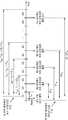
- FIG. 4is a diagram illustrating an example of a time point at which chirp signals are transmitted according to an embodiment.
- the chirp signals 311 and 313 transmitted from the electronic device 1000 and the external devices 120 and 130do not overlap each other and are received in separate window sections, Chirp signals may be transmitted and received.
- external devices assigned with indices of 2, 3, 4 ...are respectively referred to as a second device, a third device, and a fourth device ..., respectively.
- the electronic device 1000may be assigned an index value of 1.
- window sections of 1H, 2H, 3H, ..., iH based on t hellowhich is a time point at which the trigger signal is output at the first position 110
- window sections of 2D, 3D, 4D, ..., iDmay be set based on a time point at which the chirp signal 312 transmitted from the electronic device 1000 is received.
- the window period of the iDmay be set based on different time points at which the chirp signal 312 of the electronic device 1000 is received in each external device.
- the chirp signal 312may be received by each external device at different times. Accordingly, in FIG. 4 , different points in time at which the chirp signal 312 of the electronic device 1000 is received in each external device is indicated by a dotted line.
- the window sections of iH and iDare values determined based on index values of the corresponding electronic device 1000 and external devices 120 and 130, respectively, for example, (2i) shown in FIG. 4 , -1)T W (or, 2iT W ) and 2(i-1)T W to be set to 1H, 2H, 3H, ..., iH and 2D, 3D, 4D, ..., iD can
- 1His a section corresponding to the electronic device 1000 and may be set as a time section having a size of T W from the time t hello.
- the electronic device 1000may output the chirp signal 311 after receiving the trigger signal within the 1H period.
- the chirped signal 311 output from the electronic device 1000 in the 1H periodis a signal for obtaining a time t 1i required for transmission and reception of the chirp signal between the electronic device 1000 and the external devices 120 and 130, and is at least It may be received by one external device.
- 2Hmay be set as a section after the 1H section with respect to the second device having an index value of 2.
- the second devicemay output the chirp signal 220 within a 2H time period.
- the chirp signals 220 and 311 output from each device according to an embodimentmay be chirped signals having the same shape as each other. Since the chirp signals 220 and 311 according to an embodiment may be received by a plurality of different devices, each device distinguishes from which device the received chir signals 220 and 311 are output. it is necessary to do
- the chirp signal 220 output from the second device in the 2H section and the chirping signal 311 output in the 1H sectionoverlap in another device (eg, the third device or the fourth device).
- the time interval between the time T W and the time 2T Wmay be set to a period of 2H.
- time intervals iH and iD in which each chirped signal may be output or receivedmay be set for each device 1000 , 120 , 130 .
- Each of the chirped signalsmay be identified according to which section a time point at which the chirped signals are received in each of the devices 1000 , 120 , and 130 belongs.
- 2Dmay be set for a second device having an index value of 2 among the external devices 120 and 130 .
- the output chirp signal 313is received by the external device having the index value i, and the chirped signal 312 output by the electronic device 1000 is received in the 1H section. It may be a signal output from the external device after a (2i-1)T W time interval (or 2iT W ) has elapsed from the time the chirp signal 312 is received.
- iH and iDmay be set as time intervals of (2i-2)T W and (2i-1)T W according to the index values of the external devices 120 and 130 .
- iDaccording to an embodiment may be set to one of a time interval of (2i-1)T W and a time interval of 2iT W so that chirped signals output from different devices do not overlap each other.
- the values of (2i-2)T W and (2i-1)T W (or 2iT W )are, as shown in FIG. 4 , 2H, 2D, 3H, 3D ... As such, it is set so that the iD section of the same index can be continued after the iH section.
- the iD perioddoes not follow the iH period precisely because it is not based on the time when the trigger signal is output, but the time period of iH and iD compared to the time it takes for the chirp signal of the electronic device 1000 to be received by each external device. is much longer, so that in each time interval, the transmitted chirp signals can be transmitted without overlapping each other.
- the lengths of the iH and iD intervalsare not limited to the above-described examples, and the chirped signals transmitted from each other device may be transmitted without overlapping with each other, and may be determined in a time interval determined by various methods.
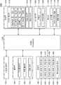
- FIG. 5is a block diagram illustrating an internal configuration of the electronic device 1000 according to an embodiment.
- FIG. 6is a block diagram illustrating an internal configuration of the electronic device 1000 according to an embodiment.
- the electronic device 1000may include a processor 1300 , a communication unit 1500 , and a memory 1700 . However, not all of the components shown in FIG. 5 are essential components of the electronic device 1000 .
- the electronic device 1000may be implemented by more components than the components illustrated in FIG. 5 , or the electronic device 1000 may be implemented by fewer components than the components illustrated in FIG. 5 .
- the electronic device 1000includes a user input unit 1100 in addition to the processor 1300 , the communication unit 1500 , and the memory 1700 .
- an output unit 1200 , a sensing unit 1400 , and an A/V input unit 1600may be further included.
- the user input unit 1100means a means for a user to input data for controlling the electronic device 1000 .
- the user input unit 1100includes a key pad, a dome switch, and a touch pad (contact capacitive method, pressure resistance film method, infrared sensing method, surface ultrasonic conduction method, integral type).
- a tension measurement methoda piezo effect method, etc.
- a jog wheela jog switch, and the like, but is not limited thereto.
- the user input unit 1100may receive a user input requesting a predetermined operation.
- the electronic device 1000may perform an operation of determining the location of the external device according to a user input.
- the output unit 1200may output an audio signal, a video signal, or a vibration signal, and the output unit 1200 may include a display unit 1210 , a sound output unit 1220 , and a vibration motor 1230 . have.
- the display unit 1210displays and outputs information processed by the electronic device 1000 .
- the display 1210may display a result of determining the location of the external device.
- the display 1210may display information about an external device on which a predetermined operation is to be performed according to a result of determining the location of the external device.
- the display unit 1210may be used as an input device in addition to an output device.
- the display unit 1210includes a liquid crystal display, a thin film transistor-liquid crystal display, an organic light-emitting diode, a flexible display, a three-dimensional display ( 3D display) and electrophoretic display (electrophoretic display) may include at least one. Also, depending on the implementation form of the electronic device 1000 , the electronic device 1000 may include two or more display units 1210 .
- the sound output unit 1220outputs audio data received from the communication unit 1500 or stored in the memory 1700 .
- the vibration motor 1230may output a vibration signal. Also, the vibration motor 1230 may output a vibration signal when a touch is input to the touch screen.
- the sound output unit 1220 and the vibration motor 1230may output a result of determining the position of the external device. Also, the sound output unit 1220 and the vibration motor 1230 may output information about an external device on which a predetermined operation is to be performed according to a result of determining the location of the external device.
- the processor 1300generally controls the overall operation of the electronic device 1000 .
- the processor 1300executes programs stored in the memory 1700 , and thus the user input unit 1100 , the output unit 1200 , the sensing unit 1400 , the communication unit 1500 , and the A/V input unit 1600 . ) can be controlled in general.
- the electronic device 1000may include at least one processor 1300 .
- the electronic device 1000may include various types of processors, such as a central processing unit (CPU), a graphics processing unit (GPU), and a neural processing unit (NPU).
- CPUcentral processing unit
- GPUgraphics processing unit
- NPUneural processing unit
- the processor 1300may be configured to process instructions of a computer program by performing basic arithmetic, logic, and input/output operations.
- the commandmay be provided to the processor 1300 from the memory 1700 or may be received through the communication unit 1500 and provided to the processor 1300 .
- the processor 1300may be configured to execute instructions according to program codes stored in a recording device such as a memory.
- the processor 1300receives the first chirp signal transmitted when the trigger signal output from the first position is received by the electronic device 1000 and when the first external device receives the trigger signal.
- the position of the first external devicemay be determined based on the difference value between the viewpoints.
- the processor 1300may determine an external device on which an operation according to a user's voice command corresponding to a trigger signal is to be performed, among at least one external device, based on the location of the first external device.
- the difference value according to an embodimentis based on a time taken for the first chirped signal to be received by the electronic device 1000 after being transmitted from the first external device and a time when the first chirped signal is received from the electronic device 1000 . can be obtained by In addition, the time it takes for the first chirp signal to be received by the electronic device 1000 after being transmitted from the first external device is determined through the signal transmission/reception operation of the electronic device 1000 and the first external device for acquiring the time, can be obtained.
- the sensing unit 1400may detect a state of the electronic device 1000 or a state around the electronic device 1000 , and transmit the sensed information to the processor 1300 .
- the sensing unit 1400includes a geomagnetic sensor 1410 , an acceleration sensor 1420 , a temperature/humidity sensor 1430 , an infrared sensor 1440 , a gyroscope sensor 1450 , and a position sensor. (eg, GPS) 1460 , a barometric pressure sensor 1470 , a proximity sensor 1480 , and at least one of an illuminance sensor 1490 , but is not limited thereto.
- GPSGPS
- the sensing unit 1400may detect a trigger signal and a chirp signal transmitted from the outside.
- the sensing unit 1400may include a sensor capable of detecting an acoustic or ultrasonic signal.
- the communication unit 1500may include one or more components that allow the electronic device 1000 to communicate with the server 2000 or an external device (not shown).
- the communication unit 1500may include a short-range communication unit 1510 , a mobile communication unit 1520 , and a broadcast receiving unit 1530 .
- Short-range wireless communication unit 1510Bluetooth communication unit, BLE (Bluetooth Low Energy) communication unit, short-range wireless communication unit (Near Field Communication unit), WLAN (Wi-Fi) communication unit, Zigbee (Zigbee) communication unit, infrared ( It may include an IrDA, infrared Data Association) communication unit, a Wi-Fi Direct (WFD) communication unit, an ultra wideband (UWB) communication unit, an Ant+ communication unit, and the like, but is not limited thereto.
- the mobile communication unit 1520transmits/receives a radio signal to and from at least one of a base station, an external terminal, and a server on a mobile communication network.
- the wireless signalmay include various types of data according to transmission/reception of a voice call signal, a video call signal, or a text/multimedia message.
- the broadcast receiver 1530receives a broadcast signal and/or broadcast-related information from the outside through a broadcast channel.
- the broadcast channelmay include a satellite channel and a terrestrial channel.
- the electronic device 1000may not include the broadcast receiver 1530 .
- the communication unit 1500may transmit/receive data required to determine the location of the first external device.
- the communication unit 1500may receive a trigger signal and a chirp signal transmitted from the outside, or may transmit a chirp signal.
- the communication unit 1500may receive an acoustic or ultrasound signal, or may transmit an ultrasound signal.
- the A/V (Audio/Video) input unit 1600is for inputting an audio signal or a video signal, and may include a camera 1610 , a microphone 1620 , and the like.
- the camera 1610may obtain an image frame such as a still image or a moving image through an image sensor in a video call mode or a shooting mode.
- the image captured through the image sensormay be processed through the processor 1300 or a separate image processing unit (not shown).
- the microphone 1620receives an external sound signal and processes it as electrical voice data.
- the microphone 1620may receive an externally output trigger signal (eg, a user's voice command) and process the trigger signal as voice data.
- the electronic device 1000may perform voice recognition on the voice data to perform an operation corresponding to the voice recognition result based on the location of each external device.
- the electronic device 1000may transmit a request signal to the external device so that an external device closest to the user's location among at least one external device may perform an operation corresponding to the result of the voice recognition. .
- the memory 1700may store a program for processing and control of the processor 1300 , and may also store data input to or output from the electronic device 1000 .
- the memory 1700may store data necessary to determine the location of the external device.
- the memory 1700may store the trigger signal and the chirp signals received from the outside, and the timing at which the trigger signal and the chirp signals are respectively received.
- the memory 1700may include a flash memory type, a hard disk type, a multimedia card micro type, a card type memory (eg, SD or XD memory), and a RAM.
- RAMRandom Access Memory
- SRAMStatic Random Access Memory
- ROMRead-Only Memory
- EEPROMElectrically Erasable Programmable Read-Only Memory
- PROMProgrammable Read-Only Memory
- magnetic memorymagnetic disk
- magnetic diskmay include at least one type of storage medium among optical disks.
- Programs stored in the memory 1700may be classified into a plurality of modules according to their functions, for example, may be classified into a UI module 1710 , a touch screen module 1720 , a notification module 1730 , and the like. .
- the UI module 1710may provide a specialized UI, GUI, or the like that interworks with the electronic device 1000 for each application.
- the touch screen module 1720may detect a touch gesture on the user's touch screen and transmit information about the touch gesture to the processor 1300 .
- the touch screen module 1720according to some embodiments may recognize and analyze a touch code.
- the touch screen module 1720may be configured as separate hardware including a controller.
- a tactile sensoris an example of a sensor for detecting a touch of a touch screen.
- a tactile sensorrefers to a sensor that senses a touch of a specific object to the extent or higher than that felt by a human.
- the tactile sensormay sense various information such as the roughness of the contact surface, the hardness of the contact object, and the temperature of the contact point.
- the user's touch gesturemay include a tap, touch & hold, double tap, drag, pan, flick, drag and drop, swipe, and the like.
- the notification module 1730may generate a signal for notifying the occurrence of an event in the electronic device 1000 .
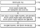
- FIG. 7is a flowchart illustrating a method of determining a location of an external device according to an exemplary embodiment.
- the electronic device 1000may receive a trigger signal output from a first position.
- the electronic device 1000may receive a voice command uttered by the user as a trigger signal at the first location.
- the electronic device 1000may determine the location of at least one external device around the electronic device 1000 to perform an operation corresponding to the trigger signal. For example, the electronic device 1000 may request, among at least one external device, to perform an operation corresponding to the trigger signal from an external device that is closest to the user's first location. Also, the electronic device 1000 is an external device that is closest to the user's first location among at least one external device capable of performing an operation corresponding to the trigger signal, and corresponds to the trigger signal. You can request an action to be performed.
- the electronic device 1000may receive a chirp signal from at least one external device.
- At least one external devicemay transmit a chirp signal (a first chirping signal) upon receiving the same signal as the trigger signal received by the electronic device 1000 in operation 710 .
- the external devicemay receive a trigger signal at a time different from that of the electronic device 1000 according to a position difference from the electronic device 1000 . For example, as the distance between the user's first location and the external device increases, the external device may receive the trigger signal at a later time.
- the electronic device 1000based on the time when the chir signal received in operation 720 is received, between the time when the trigger signal is received from the electronic device 1000 and the time when the trigger signal is received from the external device. difference can be obtained.
- the difference valuewhich may be obtained in operation 730 , is obtained based on a time taken for the chirp signal to be received by the electronic device 1000 after being transmitted from the external device and a time point at which the chirp signal is received from the electronic device 1000 .
- the time taken for the chirp signal to be received by the electronic device 1000 after being transmitted from the external devicemay be obtained in advance by the electronic device 1000 through an additional operation of the electronic device 1000 or , may be acquired at a later time point after the chirp signal is received.
- the time it takes for the chirp signal to be received by the electronic device 1000 after being transmitted from the external deviceis when the second chir signal is transmitted from the electronic device 1000 to the external device, and the It may be obtained as the third chirp signal is transmitted to the electronic device 1000 .
- the time it takes for the second chir signal and the third chirp signal to be transmitted and received between the electronic device 1000 and the external deviceis obtained as a time taken for the chirp signal to be transmitted and received to obtain the difference value.
- the electronic device 1000may determine the location of the external device based on the difference value obtained in operation 730 . For example, when the difference value is a negative value, as the absolute value of the difference value increases, it may be determined that the external device is the device closest to the user's first location. Also, when the difference value is a positive value, it may be determined that the external device is the device closest to the user's first location as the absolute value of the difference value is smaller.
- the electronic device 1000may transmit a signal requesting a necessary operation according to a trigger signal to an external device closest to the user.
- the external devicemay perform an operation according to the trigger signal.
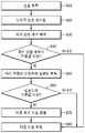
- FIG. 8is a flowchart illustrating a method of detecting a double chirped signal according to an embodiment.
- the electronic device 1000may acquire a signal from the outside.
- the electronic device 1000may determine whether a signal received from the outside is a double chirped signal according to an embodiment in steps 820 to 870 below.
- the first chirped signal, the second chirped signal, and the third chirped signal according to an embodimentmay be transmitted as the above-described double chirped signal.
- a single chirp signal that may be transmitted from each external device or electronic device 1000 according to an embodimentmay be generated according to Equation 3 below.
- a double chirped signal in which a single chirped signal according to Equation 3 is continuously transmitted twicemay be transmitted from an external device as a chirp signal.
- Trepresents the length of a single chirp signal, for example, T may be set to 50 ms.
- f 0 and f 1are frequencies of the first section and the last section, respectively, and may be set to values at which the operation of determining the location of the external device according to an embodiment can be optimally performed.
- f 0 and f 1may be set to 18 kHz and 20.5 kHz, respectively.
- the electronic device 1000may perform filtering on the received signal.
- a signal of a frequency band from f 0 to f 1 preset according to Equation 3may be obtained as a double chirped signal, and signals of other frequency bands may be filtered as a noise signal.
- signals of other frequency bandsmay be filtered as a noise signal.
- a signal outside the frequency band from f 0 to f 1may be filtered as a noise signal by a band-pass finite impulse response (FIR) filter, an infinite impulse filter (IIR), or the like for filtering the noise signal.
- FIRband-pass finite impulse response
- IIRinfinite impulse filter
- the electronic device 1000may obtain an autocorrelation coefficient according to the autocorrelation function. According to the double chirped signal according to Equation 3, it can be easily identified from other signals according to an autocorrelation function.
- Equation 4it may be determined whether the received signal is a transmitted double chirped signal according to an embodiment.
- a correlation coefficientmay be obtained.
- the electronic device 1000may determine whether the autocorrelation coefficient obtained in operation 830 is equal to or greater than a reference value. For example, when the autocorrelation coefficient has a value between 0.6 and 0.8, the electronic device 1000 may additionally determine whether the signal obtained in operation 810 is a double chirped signal in steps 850 to 870 below.
- the electronic device 1000may obtain a correlation between the pre-stored signal y and the signal x acquired in operation 810 according to Equation (4).
- the pre-stored signal ymay be a pre-stored pattern signal as a signal corresponding to a single chirped signal or a double chirped signal.
- the electronic device 1000may determine whether the degree of correlation obtained in operation 850 is equal to or greater than a reference value. For example, when the correlation has a value between 0.15 and 0.6, in operation 870 , the electronic device 1000 may detect the signal obtained in operation 810 as a double chirped signal.
- step 810when the correlation is less than or equal to the reference value, it is determined that the signal obtained in step 810 is not a double chirped signal. action can be performed.
- the electronic device 1000may detect a double chirped signal by performing operations 810 to 870 with respect to other signals additionally received thereafter.
- FIG. 9is a diagram illustrating an example of a buffer in which a chirp signal is stored according to an embodiment.
- a chirped signal(eg, a double chirped signal) transmitted from the electronic device 1000 or an external device overlaps an input buffer and an output buffer of the electronic device 1000 or an external device to which the chirp signal is transmitted. can be saved.
- the chirp signal stored in the output buffermay be used to transmit the chirp signal from the electronic device 1000 or an external device. For example, after the chirp signal is first stored in the output buffer of the electronic device 1000 or the external device, the chirp signal stored in the output buffer may be output (eg, transmitted).
- the chirp signal stored in the input buffermay be used in the electronic device 1000 or an external device to process an operation related to the transmitted chirp signal (eg, acquiring a transmission time of the chirp signal). For example, after the chirp signal is first stored in the output buffer of the electronic device 1000 or the external device, the same signal as the chirp signal may be stored in the input buffer. Also, based on the chirp signal stored in the input buffer, the electronic device 1000 or the external device may perform an operation according to an embodiment (eg, acquiring a transmission time of the chirp signal).
- the difference between the transmission time of the chirp signal stored in the input buffer and the output bufferis the time at which the chirp signal is recorded in the input buffer and the time at which the chirp signal is recorded in the output buffer, t IN and t OUT . difference can be obtained.
- the chirp signal transmitted from the electronic device 1000 or the external deviceis first stored in the output buffer and then stored in the input buffer. Then, it may be stored in the output buffer, and the time difference may be obtained according to Equation 5 above.
- the transmission time of the chir signal transmitted from the devicemay be obtained based on the chirp signal stored in the input buffer, for example, the transmission time of the chir signal transmitted after time t IN0 from the time t d. , t d +t IN0 -T R may be determined as a time point.
- the time of transmission of the chirp signal according to an embodimentis not limited to the above-described example, and may be obtained according to various methods.
- An external device determined to exist in a position closest to the user among at least one external devicemay be determined as a device to perform an operation according to the user's voice command.
- the device-readable storage mediummay be provided in the form of a non-transitory storage medium.
- 'non-transitory storage medium'is a tangible device and only means that it does not contain a signal (eg, electromagnetic wave). It does not distinguish the case where it is stored as
- the 'non-transitory storage medium'may include a buffer in which data is temporarily stored.
- the method according to various embodiments disclosed in this documentmay be provided as included in a computer program product.
- Computer program productsmay be traded between sellers and buyers as commodities.
- the computer program productis distributed in the form of a device-readable storage medium (eg compact disc read only memory (CD-ROM)), or through an application store (eg Play StoreTM) or on two user devices (eg, It can be distributed (eg downloaded or uploaded) directly, online between smartphones (eg: smartphones).
- a portion of the computer program producteg, a downloadable app
- a machine-readable storage mediumsuch as a memory of a manufacturer's server, a server of an application store, or a relay server. It may be temporarily stored or temporarily created.
- unitmay be a hardware component such as a processor or circuit, and/or a software component executed by a hardware component such as a processor.
Landscapes
- Engineering & Computer Science (AREA)
- Radar, Positioning & Navigation (AREA)
- Remote Sensing (AREA)
- Physics & Mathematics (AREA)
- Computer Networks & Wireless Communication (AREA)
- General Physics & Mathematics (AREA)
- Signal Processing (AREA)
- Acoustics & Sound (AREA)
- Measurement Of Velocity Or Position Using Acoustic Or Ultrasonic Waves (AREA)
- Telephone Function (AREA)
Abstract
Description
Translated fromKorean본 개시는, 외부 장치의 위치를 판단하는 전자 장치 및 그 동작 방법에 관한 것이다.The present disclosure relates to an electronic device for determining a location of an external device and an operating method thereof.
사용자의 입력을 수신한 전자 장치는, 사용자 주변의 다양한 외부 장치 중에서, 적어도 하나의 외부 장치에, 사용자의 입력에 따른 동작을 요청할 수 있다. 예를 들면, 전자 장치는, 사용자 주변에 존재하는 외부 장치 중, 사용자에게 가장 가까이 위치하는 외부 장치로 요청을 전송할 수 있다.Upon receiving the user's input, the electronic device may request an operation according to the user's input from at least one external device among various external devices around the user. For example, the electronic device may transmit a request to an external device located closest to the user among external devices existing around the user.
따라서, 전자 장치는, 사용자와 적어도 하나의 외부 장치 간의 거리에 기초하여, 사용자의 입력에 따른 요청을 전송할 장치를 결정할 수 있다.Accordingly, the electronic device may determine a device to transmit a request according to the user's input based on the distance between the user and the at least one external device.
다만, 사용자 또는 외부 장치의 위치가 실시간으로 변경될 수 있는 경우, 전자 장치는 사용자와 외부 장치 간 거리를 빠르고 정확하게 획득할 수 있는 방법이 필요하다.However, when the location of the user or the external device can be changed in real time, the electronic device needs a method for quickly and accurately acquiring the distance between the user and the external device.
본 개시가 해결하고자 하는 과제는 전술한 문제를 해결하기 위한 것으로서, 외부 장치의 위치를 추정하는 전자 장치 및 그 동작 방법을 제공하기 위한 것이다.SUMMARY OF THE INVENTION An object of the present disclosure is to solve the above-described problem, and to provide an electronic device for estimating a location of an external device and an operating method thereof.
또한, 상기 방법을 컴퓨터에서 실행시키기 위한 프로그램을 기록한 컴퓨터로 읽을 수 있는 기록매체를 제공하는 데 있다. 해결하려는 기술적 과제는 상기된 바와 같은 기술적 과제들로 한정되지 않으며, 또 다른 기술적 과제들이 존재할 수 있다.Another object of the present invention is to provide a computer-readable recording medium in which a program for executing the method in a computer is recorded. The technical problem to be solved is not limited to the technical problems as described above, and other technical problems may exist.
도 1은 일 실시 예에 의한 적어도 하나의 외부 장치의 위치를 판단하는 방법의 일 예를 나타낸 도면이다.1 is a diagram illustrating an example of a method of determining a location of at least one external device according to an embodiment.
도 2는 일 실시 예에 의한 외부 장치의 위치를 판단하는 방법의 일 예를 나타낸 도면이다.2 is a diagram illustrating an example of a method of determining a location of an external device according to an embodiment.
도 3은 일 실시 예에 의한 전자 장치와 외부 장치 간 처프 신호가 수신되는데 걸리는 시간인, t1i값을 구하는 일 예를 나타낸 도면이다.3 is a diagram illustrating an example of obtaining a value oft 1i , which is a time taken for a chirp signal to be received between an electronic device and an external device, according to an embodiment.
도 4는 일 실시 예에 의한 처프 신호들이 전송되는 시점의 일 예를 나타낸 도면이다.4 is a diagram illustrating an example of a time point at which chirp signals are transmitted according to an embodiment.
도 5는 일 실시 예에 의한 전자 장치의 내부 구성을 설명하기 위한 블록도이다.5 is a block diagram illustrating an internal configuration of an electronic device according to an exemplary embodiment.
도 6은 일 실시 예에 의한 전자 장치의 내부 구성을 설명하기 위한 블록도이다.6 is a block diagram illustrating an internal configuration of an electronic device according to an embodiment.
도 7은 일 실시 예에 의한 외부 장치의 위치를 판단하는 방법을 나타내는 순서도이다.7 is a flowchart illustrating a method of determining a location of an external device according to an exemplary embodiment.
도 8은 일 실시 예에 의한 더블 처프 신호를 검출하는 방법을 나타낸 순서도이다.8 is a flowchart illustrating a method of detecting a double chirped signal according to an embodiment.
도 9는 일 실시 예에 의한 처프 신호가 저장되는 버퍼의 일 예를 나타낸 도면이다.9 is a diagram illustrating an example of a buffer in which a chirp signal is stored according to an embodiment.
상술한 기술적 과제를 달성하기 위한 기술적 수단으로서, 본 개시의 제1 측면은, 전자 장치에서, 외부 장치의 위치를 판단하는 방법에 있어서, 제1 위치에서 출력된 트리거 신호를 수신하는 단계; 상기 트리거 신호가 수신된 이후, 상기 트리거 신호가, 상기 전자 장치와 다른 위치에 존재하는 적어도 하나의 외부 장치 중 제1 외부 장치에서 수신됨에 따라, 상기 제1 외부 장치로부터 전송된 제1 처프 신호를 수신하는 단계; 상기 제1 처프 신호가 수신된 시점에 기초하여, 상기 전자 장치에서 상기 트리거 신호가 수신된 시점과 상기 제1 외부 장치에서 상기 트리거 신호가 수신된 시점간의 차이값을 획득하는 단계; 및 상기 차이값에 기초하여, 상기 제1 외부 장치의 위치를 판단하는 단계를 포함하는, 방법을 제공할 수 있다. As a technical means for achieving the above-described technical problem, a first aspect of the present disclosure, in an electronic device, a method for determining a position of an external device, the method comprising: receiving a trigger signal output at a first position; After the trigger signal is received, as the trigger signal is received by a first external device among at least one external device located at a different location from the electronic device, the first chirp signal transmitted from the first external device receiving; acquiring a difference value between a time point at which the trigger signal is received by the electronic device and a time point at which the trigger signal is received at the first external device, based on a time point at which the first chir signal is received; and determining a position of the first external device based on the difference value.
또한, 본 개시의 제2 측면은, 외부 장치의 위치를 판단하는 전자 장치에 있어서, 제1 위치에서 출력된 트리거 신호를 수신하고, 상기 트리거 신호가 수신된 이후, 상기 트리거 신호가, 상기 전자 장치와 다른 위치에 존재하는 적어도 하나의 외부 장치 중 제1 외부 장치에서 수신됨에 따라, 상기 제1 외부 장치로부터 전송된 제1 처프 신호를 수신하는 통신부; 상기 제1 처프 신호가 수신된 시점에 기초하여, 상기 전자 장치에서 상기 트리거 신호가 수신된 시점과 상기 제1 외부 장치에서 상기 트리거 신호가 수신된 시점간의 차이값을 획득하고, 상기 차이값에 기초하여, 상기 제1 외부 장치의 위치를 판단하는 적어도 하나의 프로세서; 및 상기 전자 장치에서 수신된 트리거 신호 및 상기 제1 처프 신호를 저장하는 메모리를 포함하는, 전자 장치를 제공할 수 있다. Also, in a second aspect of the present disclosure, in the electronic device for determining the position of the external device, the trigger signal output from the first position is received, and after the trigger signal is received, the trigger signal is generated by the electronic device a communication unit configured to receive a first chirp signal transmitted from the first external device in response to being received by a first external device among at least one external device located at a location different from the first external device; Obtaining a difference value between a time point at which the trigger signal is received by the electronic device and a time point at which the trigger signal is received at the first external device based on a time point at which the first chir signal is received, and based on the difference value at least one processor for determining a location of the first external device; and a memory configured to store the trigger signal and the first chirp signal received from the electronic device.
또한, 본 개시의 제3 측면은, 제1 측면의 방법을 수행하도록 하는 프로그램이 저장된 기록매체를 제공할 수 있다.In addition, a third aspect of the present disclosure may provide a recording medium in which a program for performing the method of the first aspect is stored.
아래에서는 첨부한 도면을 참조하여 본 발명이 속하는 기술 분야에서 통상의 지식을 가진 자가 용이하게 실시할 수 있도록 본 발명의 실시예를 상세히 설명한다. 그러나 본 발명은 여러 가지 상이한 형태로 구현될 수 있으며 여기에서 설명하는 실시예에 한정되지 않는다. 그리고 도면에서 본 발명을 명확하게 설명하기 위해서 설명과 관계없는 부분은 생략하였으며, 명세서 전체를 통하여 유사한 부분에 대해서는 유사한 도면 부호를 붙였다.DETAILED DESCRIPTION OF THE PREFERRED EMBODIMENTS Hereinafter, embodiments of the present invention will be described in detail with reference to the accompanying drawings so that those of ordinary skill in the art can easily implement them. However, the present invention may be embodied in many different forms and is not limited to the embodiments described herein. And in order to clearly explain the present invention in the drawings, parts irrelevant to the description are omitted, and similar reference numerals are attached to similar parts throughout the specification.
명세서 전체에서, 어떤 부분이 다른 부분과 "연결"되어 있다고 할 때, 이는 "직접적으로 연결"되어 있는 경우뿐 아니라, 그 중간에 다른 소자를 사이에 두고 "전기적으로 연결"되어 있는 경우도 포함한다. 또한 어떤 부분이 어떤 구성요소를 "포함"한다고 할 때, 이는 특별히 반대되는 기재가 없는 한 다른 구성요소를 제외하는 것이 아니라 다른 구성요소를 더 포함할 수 있는 것을 의미한다.Throughout the specification, when a part is "connected" with another part, this includes not only the case of being "directly connected" but also the case of being "electrically connected" with another element interposed therebetween. . In addition, when a part "includes" a certain component, this means that other components may be further included, rather than excluding other components, unless otherwise stated.
이하 첨부된 도면을 참고하여 본 발명을 상세히 설명하기로 한다.Hereinafter, the present invention will be described in detail with reference to the accompanying drawings.
도 1은 일 실시 예에 의한 적어도 하나의 외부 장치의 위치를 판단하는 방법의 일 예를 나타낸 도면이다.1 is a diagram illustrating an example of a method of determining a location of at least one external device according to an embodiment.
도 1을 참조하면, 제1 위치(110)에서 트리거 신호(ex. Hello)가 출력됨에 따라, 전자 장치(1000) 및 적어도 하나의 외부 장치(120, 130)에서, 트리거 신호를 수신할 수 있다.Referring to FIG. 1 , as a trigger signal (eg, Hello) is output at a
일 실시 예에 의하면 사용자가 제1 위치(110)에서, "Hello"를 포함하는 음성을 발화함으로써, "Hello"를 포함하는 트리거 신호가 출력될 수 있다. 전자 장치(1000) 및 적어도 하나의 외부 장치(120, 130)는, 사용자에 의해 발화된 "Hello" 음성을 포함하는 오디오 신호를, 트리거 신호로서 수신할 수 있다.According to an embodiment, when the user utters a voice including “Hello” at the
일 실시 예에 의한 전자 장치(1000)는, 트리거 신호를 수신함에 따라, 적어도 하나의 외부 장치(120, 130)의 위치를 판단할 수 있다. 따라서, 전자 장치(1000)는 적어도 하나의 외부 장치(120, 130) 중 상기 트리거 신호가 출력된 이후 사용자에 의하여 발화된 음성 명령에 따른 동작이 수행될 장치를 결정할 수 있다.The
일 실시 예에 따르면, "Hello"를 포함하는 트리거 신호가 출력된 후, 사용자에 의하여, 음성 명령을 포함하는 오디오 신호가 제1 위치(110)에서 출력될 수 있다. 일 실시 예에 의한 전자 장치(1000)는, 트리거 신호에 기초하여, 적어도 하나의 외부 장치의 위치를 판단함으로써, 적어도 하나의 외부 장치(120, 130) 중 사용자의 음성 명령이 수행될 장치를 결정할 수 있다.According to an embodiment, after a trigger signal including “Hello” is output, an audio signal including a voice command may be output from the
일 실시 예에 의한 트리거 신호는, 상술한 예에 한하지 않고, 사용자의 음성 명령을 포함하는 신호일 수도 있다. 따라서, 전자 장치(1000)는, 트리거 신호를 수신한 이후에,The trigger signal according to an embodiment is not limited to the above-described example, and may be a signal including a user's voice command. Accordingly, the
예를 들면, 적어도 하나의 외부 장치(120, 130) 중 제1 위치(110)에 가장 가까이에 위치한 장치가, 사용자의 음성 명령에 대응하는 동작이 수행될 장치로 결정될 수 있다.For example, a device located closest to the
또한, 일 실시 예에 따르면, 전자 장치(1000)는, 사용자의 음성 명령에 대응하는 동작(ex. 라이트를 켜는 동작)을 수행할 수 있는 적어도 하나의 외부 장치를 식별하고, 각 외부 장치에 대해 판단된 위치에 따라, 동작이 수행될 외부 장치를 결정할 수 있다. 일 실시 예에 의한 전자 장치(1000)는, 식별된 적어도 하나의 외부 장치 중, 제1 위치(110)에 가장 가까이에 위치한 외부 장치에 의해 상기 동작(ex. 라이켜를 켜는 동작)이 수행되도록, 상기 외부 장치를 제어할 수 있다. 일 실시 예에 의한 제1 위치(110)에 가장 가까이에 위치한 외부 장치는, 일 실시 예에 따라 적어도 하나의 외부 장치에 대하여 판단된 위치에 기초하여 결정될 수 있다.Also, according to an embodiment, the
또한, 일 실시 예에 따르면, 전자 장치(1000)는, 각 외부 장치에 대해 판단된 위치에 따라, 사용자의 음성 명령을 전달할 적어도 하나의 외부 장치를 결정하고, 결정된 적어도 하나의 외부 장치로 사용자의 음성 명령을 전달할 수 있다.Also, according to an embodiment, the
예를 들어, 일정 크기의 공간(ex. 방, 자동차 내부)에, 사용자, 전자 장치(1000) 및 외부 장치(120, 130)가 존재하는 경우, 전자 장치(1000)는, 일 실시 예에 따라서, 외부 장치(120, 130)와 사용자(제1 위치(110)) 간의 상대적인 거리에 따라서, 사용자의 음성 명령이 수행되거나 전달될 외부 장치(120, 130)를 결정할 수 있다.For example, when the user, the
상술한 예에 한하지 않고, 적어도 하나의 외부 장치에 대하여 판단된 위치에 기초하여, 적어도 하나의 외부 장치에 대한 다양한 동작이 수행될 수 있다.The above-described example is not limited, and various operations for the at least one external device may be performed based on the determined position of the at least one external device.
일 실시 예에 의한 전자 장치(1000)는, 사용자에 의해 발화된 트리거 신호를 수신함에 따라, 사용자의 음성 명령이 수행될 장치를 결정하기 위하여, 각 외부 장치(120, 130)의 위치를 판단할 수 있는 장치일 수 있다.The
일 실시 예에 의한 외부 장치(120, 130)는, 전자 장치(1000)와 같이, 사용자에 의해 발화된 트리거 신호를 수신함에 따라, 전자 장치(1000)에 의해 각 외부 장치(120, 130)의 위치를 판단하기 위한 처프 신호를 출력시키는 장치일 수 있다. 또한, 외부 장치(120, 130)는 전자 장치(1000)의 결정에 따라서, 트리거 신호 이후에 발화된 사용자의 음성 명령에 따른 동작을 수행할 수 있는 장치일 수 있다.The
일 실시예에 따른 전자 장치(1000) 및 적어도 하나의 외부 장치(120, 130)는 다양한 형태로 구현될 수 있다. 예를 들어, 본 명세서에서 기술되는 전자 장치(1000) 및 적어도 하나의 외부 장치(120, 130) 중 적어도 하나의 장치는, 디지털 카메라, 스마트 폰(smart phone), 노트북 컴퓨터(laptop computer), 태블릿 PC, 전자북 단말기, 디지털방송용 단말기, PDA(Personal Digital Assistants), PMP(Portable Multimedia Player), 네비게이션, MP3 플레이어, 차량(vehicle) 등이 있을 수 있으나, 이에 한정되는 것은 아니다.The
본 명세서에서 기술되는 전자 장치(1000) 및 적어도 하나의 외부 장치(120, 130) 중 적어도 하나의 장치는 사용자에 의해 착용될 수 있는 장치(wearable device)일 수 있다. 웨어러블 디바이스는 액세서리 형 장치(예컨대, 시계, 반지, 팔목 밴드, 발목 밴드, 목걸이, 안경, 콘택트 렌즈), 머리 착용형 장치(head-mounted-device(HMD)), 직물 또는 의류 일체형 장치(예: 전자 의복), 신체 부착형 장치(예컨대, 스킨 패드(skin pad)), 또는 생체 이식형 장치(예: implantable circuit) 중 적어도 하나를 포함할 수 있으나, 이에 한정되는 것은 아니다. 이하에서는, 설명의 편의상, 전자 장치(1000)가 스마트 폰이고, 적어도 하나의 외부 장치(120, 130)는, 사용자 주변의 다양한 종류의 IoT(internet of things) 장치인 경우를 예로 들어 설명하기로 한다.At least one of the
일 실시 예에 의한 전자 장치(1000) 및 적어도 하나의 외부 장치(120, 130)는, 각각 다른 위치에서, 트리거 신호를 수신하므로, 각 장치에서 트리거 신호를 수신하는 시간이 서로 다를 수 있다. 일 실시 예에 의하면, 소리가 공기 중에서 전파되는 속도(ex. 331.5m/s)에 따라, 트리거 신호가 이동함에 따라서, 제1 위치(110)와 가까운 장치일수록, 더 빨리 트리거 신호를 수신할 수 있다.Since the
일 실시 예에 의한 전자 장치(1000)를 제외한 적어도 하나의 외부 장치(120, 130)는, 트리거 신호를 수신함에 따라서, 처프 신호를 출력할 수 있다. 일 실시 예에 의한 처프 신호는, 각 외부 장치(120, 130)의 위치를 판단하기 위한 신호로, 트리거 신호가 수신됨에 따라 각 외부 장치(120, 130)에서, 출력될 수 있다. 각 외부 장치(120, 130)에서 출력된 처프 신호는, 전자 장치(1000)에서 수신될 수 있다.At least one
일 실시 예에 의한 처프 신호는, 공기 중으로 전파될 수 있는 신호로, 예를 들면, 처프 신호는, 가청 주파수 대역(ex. 16Hz~20kHz) 밖에 속하는 초음파 신호일 수 있다. 따라서, 일 실시 예에 의한 전자 장치(1000) 및 외부 장치(120, 130)는, 처프 신호 및 트리거 신호를 수신하기 위한 별도의 하드웨어 구성을 구비할 필요 없이, 초음파 신호와 음성 신호를 수신할 수 있는 마이크 또는 센서와, 초음파 신호를 출력할 수 있는 스피커 등의 구성만으로, 일 실시 예에 의한 외부 장치의 위치를 판단하는 동작을 수행할 수 있다.The chirped signal according to an embodiment is a signal that can be propagated in the air. For example, the chirped signal may be an ultrasonic signal that belongs to an audible frequency band (eg, 16Hz to 20kHz). Accordingly, the
상술한 예에 한하지 않고, 처프 신호는 음성 신호를 포함한 다양한 종류의 신호일 수 있다.Without being limited to the above-described example, the chirp signal may be various types of signals including a voice signal.
일 실시 예에 의한 전자 장치(1000)는, 트리거 신호를 수신한 시점 및 처프 신호가 전자 장치(1000)에서 수신된 시점에 기초하여, 제1 위치(110)를 기준으로 한 각 외부 장치(120, 130)의 상대적인 위치를 판단할 수 있다. 일 실시 예에 의한 제1 위치(110)는, 음성 명령을 발화할 수 있는 사용자의 위치와 대응될 수 있다.The
일 실시 예에 의하면, 트리거 신호를 수신한 시점 및 처프 신호가 수신된 시점에 기초하여 획득된, 전자 장치(1000)에서 트리거 신호가 수신된 시점과, 각 외부 장치(120, 130)에서 트리거 신호가 수신된 시점 간의 차이값에 따라서, 외부 장치(120, 130)의 위치가 판단될 수 있다.According to an embodiment, the trigger signal is received from the
일 실시 예에 의하면, 상기 차이값은, 제1 위치(110)와 각 외부 장치(120, 130) 간의 거리에 비례하는 값을 포함할 수 있다.According to an embodiment, the difference value may include a value proportional to the distance between the
예를 들어, 상기 차이값이 0보다 작은 경우, 전자 장치(1000)보다 외부 장치(120, 130)가 제1 위치(110)에 더 가까이 위치한 것으로 판단될 수 있다. 반면, 외부 장치(120, 130)에 대한 상기 차이값이 0보다 큰 경우, 상기 외부 장치(120, 130)보다 전자 장치(1000)가 제1 위치에 더 가까운 것으로 판단될 수 있다. 또한, 상기 차이값이 0인 경우, 전자 장치(1000)와 동일한 위치에 외부 장치(120, 130)가 존재하는 것으로 판단될 수 있다.For example, when the difference value is less than 0, it may be determined that the
또한, 상기 차이값이 0보다 작은 경우, 상기 차이값의 절대값이 클수록, 외부 장치(120, 130)가 제1 위치(110)에 더 가까이 위치한 것으로 판단될 수 있다. 또한, 상기 차이값이 0보다 큰 경우, 상기 차이값의 절대값이 클수록, 외부 장치(120, 130)가 제1 위치(110)에서 더 멀리 위치한 것으로 판단될 수 있다.Also, when the difference value is less than 0, it may be determined that the
따라서, 일 실시 예에 의하면, 전자 장치(1000)는, 적어도 하나의 외부 장치(120, 130) 중 상기 차이값이 가장 작은 외부 장치(120, 130)를, 트리거 신호 이후에 발화될 사용자의 음성 명령에 대응하는 동작이 수행될 장치로 결정할 수 있다.Accordingly, according to an embodiment, the
또한, 일 실시 예에 의한 전자 장치(1000)는, 상술한 예에 한하지 않고, 상기 차이값에 기초하여 판단된 각 외부 장치(120, 130)의 위치에 기초하여, 다양한 동작을 수행할 수 있다.Also, the
일 실시 예에 의한 전자 장치(1000)는, 각 외부 장치(120, 130)로부터 출력된 처프 신호가 전자 장치(1000)에서 수신된 시점에 기초하여, 각 외부 장치(120, 130)에서 트리거 신호가 수신된 시점에 관한 정보 없이도, 전자 장치(1000)에서 트리거 신호가 수신된 시점과, 각 외부 장치(120, 130)에서 트리거 신호가 수신된 시점 간의 차이값을 획득할 수 있다.In the
예를 들면, 각 외부 장치(120, 130)에서 트리거 신호가 수신됨에 따라, 트리거 신호가 각 외부 장치(120, 130)에서 수신된 시점으로부터 미리 정해진 시간(TW)이 경과된 후, 처프 신호가 출력될 수 있다. 일 실시 예에 의하면, 전자 장치(1000)에서 각 외부 장치(120, 130)의 처프 신호가 수신된 시점에서, 각 외부 장치(120, 130)에서 전자 장치(1000)로 처프 신호가 전달되는데 걸리는 시간 및 미리 정해진 시간(TW)을 뺀 값은, 각 외부 장치(120, 130)에서 트리거 신호가 수신된 시점과 대응될 수 있다. 따라서, 각 외부 장치(120, 130)에서 출력된 처프 신호가 전자 장치(1000)에서 수신된 시점에 기초하여, 상술한 차이값이 획득될 수 있다.For example, as a trigger signal is received from each of the
일 실시 예에 따른 각 외부 장치(120, 130)에서 전자 장치(1000)로 처프 신호가 전달되는데 걸리는 시간은, 각 외부 장치(120, 130) 및 전자 장치(1000)에 의하여 상기 전달 시간을 획득하기 위한 동작이 추가적으로 수행됨으로써, 획득될 수 있다. 예를 들면, 각 장치(1000, 120, 130) 중 적어도 하나의 장치의 위치가 변경되거나, 주기적으로, 상기 전달 시간을 획득하기 위한 동작이 수행됨으로써, 각 외부 장치(120, 130) 및 전자 장치(1000) 간 처프 신호가 전달되는데 걸리는 시간이 획득될 수 있다.The time it takes for the chirp signal to be transmitted from each of the
일 실시 예에 의한 각 장치들 간 처프 신호가 전달되는데 걸리는 시간은, 각 외부 장치(120, 130) 및 전자 장치(1000) 간 거리에 비례할 수 있다. 예를 들어, 외부 장치(120, 130) 및 전자 장치(1000) 간 거리가 멀수록, 외부 장치(120, 130) 및 전자 장치(1000) 간 처프 신호가 전달되는데 걸리는 시간이 길어질 수 있다.According to an embodiment, the time it takes for the chirp signal to be transmitted between the respective devices may be proportional to the distance between each of the
일 실시 예에 의한 상기 전달 시간은, 후술될 도 3과 같이, 외부 장치(120, 130) 및 전자 장치(1000) 간 처프 신호가 송수신되는 동작에 따라서, 획득될 수 있다.The transfer time according to an embodiment may be obtained according to an operation in which a chirp signal is transmitted/received between the
도 2는 일 실시 예에 의한 외부 장치(120, 130)의 위치를 판단하는 방법의 일 예를 나타낸 도면이다.2 is a diagram illustrating an example of a method of determining the location of the
도 2를 참조하면, thello 시점에서, 제1 위치(110)에 존재하는 사용자에 의하여, 음성이 발화됨으로써, 트리거 신호가 출력될 수 있다. 일 실시 예에 의한 전자 장치(1000) 및 외부 장치(120, 130)는 각각 thello1 및 thelloi 시점에서, 상기 트리거 신호를 수신할 수 있다.Referring to FIG. 2 ,at the time t hello , the user present at the
일 실시 예에 의한 thelloi 시점은, 외부 장치(120, 130)에서, 트리거 신호(210)가 모두 수신되는 시점으로 설정될 수 있다. 상술한 예에 한하지 않고, thelloi 시점은 트리거 신호(210)가 외부 장치(120, 130)에서 수신되기 시작하는 시점으로 결정되거나, 트리거 신호(210)가 외부 장치(120, 130)에서 절반정도 수신된 시점으로 결정될 수도 이다.The time t helloi according to an embodiment may be set to a time when all of the trigger signals 210 are received in the
thello1 및 thelloi 시점은, 제1 위치(110)와 각 장치 간의 거리에 따라, 달라질 수 있다. 따라서, 일 실시 예에 의한 thello1 및 thelloi 시점 간 차이 값은, 제1 위치(110)와 전자 장치(1000)의 간의 거리 및 제1 위치(110)와 외부 장치(120, 130) 간의 거리 차이와 대응될 수 있다.Time points thello1 and t helloi may vary according to a distance between the
또한, 일 실시 예에 의한 전자 장치(1000)는, 상기 차이값에 기초하여, 외부 장치(120, 130)와 제1 위치(110) 간의 상대적인 거리(ex. 다른 장치들 대비, 외부 장치가 제1 위치에 가까운 정도)를 판단할 수 있다.In addition, in the
일 실시 예에 의한 외부 장치(120, 130)는, 트리거 신호(210)가 모두 수신된 시점인, thelloi 시점에서, 수신된 음성 신호가 트리거 신호(210)임을 감지함에 따라, 각 외부 장치(120, 130)마다 미리 정해진 윈도우 구간((i-1)TW)이 경과된 후, 처프 신호(220)를 출력할 수 있다.The
일 실시 예에 의한 윈도우 구간((i-1)TW)은, 외부 장치(120, 130)마다 다른 값으로 미리 설정될 수 있다. 예를 들어, 각 외부 장치(120, 130)에 대해 할당된 인덱스 i 값에 따라서, 윈도우 구간((i-1)TW)이 결정될 수 있다.The window section ((i-1)TW ) according to an embodiment may be preset to a different value for each
TW는 각 외부 장치(120, 130)에서 출력되는 처프 신호(220)들이 전자 장치(1000)에서, 겹쳐져 수신되지 않도록, 미리 결정된 시간 구간을 나타내는 상수값일 수 있다. 예를 들면, TW는 전자 장치(1000)와 외부 장치(120, 130)들이 존재하는 공간의 크기에 기초하여, 전자 장치(1000)와 외부 장치(120, 130) 간 처프 신호들이 수신되는데 걸릴 수 있는 최대 시간에 따라서, 결정될 수 있다.TW may be a constant value indicating a predetermined time period so that the chirp signals 220 output from the
따라서, 일 실시 예에 의하면, 서로 다른 윈도우 구간에서 처프 신호(220)가 출력됨에 따라, 전자 장치(1000)에서, 각 외부 장치(120, 130)에서 출력되는 처프 신호(220)들은 서로 겹치지 않고 수신될 수 있다.Accordingly, according to an embodiment, as the chirped signals 220 are output in different window sections, in the
일 실시 예에 의한 각 외부 장치(120, 130)에 대한 인덱스 값은, 트리거 신호(210)가 수신되기 전에, 전자 장치(1000)에 의하여, 미리 할당될 수 있다. 예를 들면, 전자 장치(1000)는, 전자 장치(1000) 주변의 적어도 하나의 외부 장치(120, 130)를 식별함으로써, 식별된 외부 장치(120, 130)에 대해 서로 다른 인덱스 값을 각각 할당할 수 있다. 일 실시 예에 의하면, 전자 장치(1000)의 인덱스 값은, 1로 할당될 수 있고, 외부 장치(120, 130)의 인덱스 값은, 2 이상의 상수값으로 할당될 수 있다.Index values for each of the
일 실시 예에 의한 전자 장치(1000)는, 외부 장치(120, 130)로부터 처프 신호(220)를 수신받는데 걸리는 시간인, t1i를 미리 획득할 수 있다. t1i값은 전자 장치(1000)와 외부 장치(120, 130) 간 거리에 따라 결정될 수 있는 값이므로, 전자 장치(1000) 및 외부 장치(120, 130) 중 적어도 하나의 장치가 이동한 경우, 또는 주기적으로, t1i값을 획득하기 위한 동작이 수행될 수 있다. 또는, t1i값을 획득하기 위한 동작은, 트리거 신호가 전자 장치(1000) 및 외부 장치(120, 130)에서 수신됨에 따라서, 수행될 수 있다. 상술한 예에 한하지 않고, t1i값은 다양한 시점에서 결정될 수 있다.The
일 실시 예에 의하면, t1i값은, 전자 장치(1000) 및 외부 장치(120, 130)에서 처프 신호를 송수신함에 따라 측정된 시간에 기초하여 결정될 수 있다. 상술한 예에 한하지 않고, t1i값은 다양한 방법에 따라 결정될 수 있다.According to an embodiment, the t1i value may be determined based on a time measured as the
일 실시 예에 의한 전자 장치(1000)는, 외부 장치(120, 130)로부터 처프 신호(230)를 수신받은 시점인, tchirpi 시점에 기초하여, 이하 수학식 1에 따라서, 상술한 차이값인, tdiffi가 획득될 수 있다.The electronic device 1000 according to an embodiment, based on the t chirpi time point, which is the time point at which the

도 2를 참조하면, tdiffi에 기초하여, 제1 위치(110)와 전자 장치(1000) 간의 거리를 기준으로 한 외부 장치(120, 130)와 제1 위치(110) 간의 상대적인 거리를 판단할 수 있다. 예를 들면, 제1 위치(110)와 전자 장치(1000) 간의 거리를 0으로 두었을 때, 외부 장치(120, 130)와 제1 위치(110) 간의 상대적인 거리가 판단될 수 있다. 상술한 예에 한하지 않고, 전자 장치(1000)는, 다양한 방법에 따라서, tchirpi 시점에 기초하여, 외부 장치(120, 130)와 제1 위치(110) 간의 거리를 판단할 수 있다.Referring to FIG. 2 ,based on t diffi , a relative distance between the
도 3은 일 실시 예에 의한 전자 장치(1000)와 외부 장치(120, 130) 간 처프 신호가 수신되는데 걸리는 시간인, t1i값을 구하는 일 예를 나타낸 도면이다.3 is a diagram illustrating an example of obtaining a value oft 1i , which is a time taken for a chirp signal to be received between the
도 3을 참조하면, 일 실시 예에 의한 전자 장치(1000)는, TSP시점에서, 제2 처프 신호(311)를 외부 장치(120, 130)로 전송할 수 있다. 또한, 일 실시 예에 의한 외부 장치(120, 130)는, TRP 시점에서, 전자 장치(1000)로부터 수신된 제2 처프 신호(311)를 수신할 수 있다. 따라서, TSP시점과 TRP 시점 간 차이값은, 제2 처프 신호가 수신되는데 걸리는 시간인, t1i값과 대응될 수 있다.Referring to FIG. 3 , the
다만, 일 실시 예에 의한 전자 장치(1000)는, 외부 장치(120, 130)에서 측정 가능한 시점인, TRP 시점을 알 수 없다. 따라서, 외부 장치(120, 130)가, TRP 시점 이후, TRR 시점에서, 응답 신호로서, 제3 처프 신호(313)를 출력된 신호를 수신한 시점에 기초하여, 전자 장치(1000)는 t1i값을 획득할 수 있다. 일 실시 예에 의한 전자 장치(1000)는, 외부 장치(120, 130)로부터 출력된 제3 처프 신호(314)를 TSR에서 수신할 수 있다.However, the
일 실시 예에 의한 외부 장치(120, 130)는, 전자 장치(1000)가 아래 수학식 2에 따라서, t1i값을 획득할 수 있도록, TRR-TRP값을 전자 장치(1000)로 전달할 수 있다. TRR-TRP값은, 제3 처프 신호(314)가 전자 장치(1000)에서 수신된 후, 외부 장치(120, 130)에 의해 전자 장치(1000)로 다양한 통신 채널 및 방법을 통하여 전달될 수 있다.The

수학식 2에 의하면, 제2 처프 신호가 전자 장치(1000)에서 외부 장치로 전송된 시점부터 제3 처프 신호가 상기 전자 장치에서 수신되기까지 소요된 제1 시간(ex. TSR-TSP) 및 제2 처프 신호가 외부 장치에서 수신된 시점부터, 상기 제3 처프 신호가 상기 제1 외부 장치에서 상기 전자 장치로 전송되기까지 소요된 제2 시간(ex.TRR-TRP)에 기초하여, t1i값이 획득될 수 있다. 또한, t1i값은, 수학식 2와 같이, 제1 시간에서 제2 시간을 뺀 값을 2로 나눈 값으로 결정될 수 있다.According to
또한, 일 실시 예에 의하면, 제2 시간인, TRR-TRP값은 외부 장치(120, 130)의 인덱스 값에 따라 결정될 수 있는, (2i-1)TW 값 또는 2iTW 값으로 미리 설정됨에 따라, TRR-TRP값이 외부 장치(120, 130)에서 전자 장치(1000)로 전달될 필요없이, t1i값이 획득될 수 있다.In addition, according to an embodiment, the second time, TRR -TRP value, which may be determined according to the index value of the
예를 들면, 외부 장치(120, 130)는, 전자 장치(1000)의 처프 신호(312)를 수신 완료한 시점부터, (2i-1)TW 또는 2iTW 시간 구간이 경과된 후, 응답을 위한 처프 신호(313)의 출력이 완료될 수 있도록 동작할 수 있다. 따라서, 전자 장치(1000)는, 외부 장치(120, 130)의 인덱스 값에 따라 결정될 수 있는, (2i-1)TW 값 또는 2iTW 값을, TRR-TRP값 으로서 획득할 수 있다.For example, the external devices 120 and 130 transmit a response after a (2i-1)T W or 2iTW time period elapses from the time when the reception of the
일 실시 예에 의한 (2i-1)TW 값 또는 2iTW 값은, 이하 도 4에서 후술되는, 전자 장치(1000) 및 외부 장치(120, 130)에서 처프 신호들(311, 313)이 송수신되는 윈도우 구간에 결정되는 방법에 따라 결정될 수 있다.The (2i-1)TW value or the 2iTW value according to an embodiment is transmitted and received by the chirp signals 311 and 313 in the
도 4는 일 실시 예에 의한 처프 신호들이 전송되는 시점의 일 예를 나타낸 도면이다.4 is a diagram illustrating an example of a time point at which chirp signals are transmitted according to an embodiment.
도 4를 참조하면, 일 실시 예에 의하면, 전자 장치(1000) 및 외부 장치(120, 130)에서 전송되는 처프 신호들(311, 313)이 서로 겹쳐 수신되지 않도록, 각각 구분되는 윈도우 구간에서, 처프 신호들이 송수신될 수 있다.Referring to FIG. 4 , according to an embodiment, the chirp signals 311 and 313 transmitted from the
이하 설명에서, 인덱스가 각각 2, 3, 4 ...로 할당된 외부 장치들을 각각 제2 장치, 제3 장치, 제4 장치 ...로 지칭하였다. 또한, 전자 장치(1000)는 1의 인덱스 값이 할당될 수 있다.In the following description, external devices assigned with indices of 2, 3, 4 ... are respectively referred to as a second device, a third device, and a fourth device ..., respectively. Also, the
일 실시 예에 의하면, 제1 위치(110)에서 트리거 신호가 출력되는 시점인, thello를 기준으로 하는, 1H, 2H, 3H, ..., iH의 윈도우 구간이 설정될 수 있다. 또한, 각 외부 장치에서, 전자 장치(1000)로부터 전송된 처프 신호(312)가 수신된 시점을 기준으로 하는, 2D, 3D, 4D, ..., iD의 윈도우 구간이 설정될 수 있다.According to an embodiment, window sections of 1H, 2H, 3H, ..., iH based ont hello , which is a time point at which the trigger signal is output at the
iD의 윈도우 구간은, 각각의 외부 장치에서, 전자 장치(1000)의 처프 신호(312)가 수신된 서로 다른 시점을 기준으로 설정될 수 있다. 일 실시 예에 의하면, 전자 장치(1000)와 각 외부 장치 간의 거리에 따라, 처프 신호(312)는, 서로 다른 시점에서, 각 외부 장치에 의해 수신될 수 있다. 따라서, 도 4에서는, 각각의 외부 장치에서, 전자 장치(1000)의 처프 신호(312)가 수신된 서로 다른 시점을 점선으로 표시하였다.The window period of the iD may be set based on different time points at which the
일 실시 예에 의한 iH 및 iD의 윈도우 구간은, 각각 대응되는 전자 장치(1000) 및 외부 장치(120, 130)의 인덱스 값에 기초하여 결정된 값, 예를 들면, 도 4에 도시된, (2i-1)TW (또는, 2iTW) 및 2(i-1)TW 값에 따라서, 1H, 2H, 3H, ..., iH 및 2D, 3D, 4D, ..., iD로 설정될 수 있다.The window sections of iH and iD according to an embodiment are values determined based on index values of the corresponding
일 실시 예에 의한 윈도우 구간 중, 1H는, 전자 장치(1000)와 대응되는 구간으로, thello 시점부터 TW 크기의 시간 구간으로 설정될 수 있다. 일 실시 예에 의한 전자 장치(1000)는 1H 구간 내에서, 트리거 신호를 수신한 후, 처프 신호(311)를 출력할 수 있다. 1H 구간에서 전자 장치(1000)로부터 출력된 처프 신호(311)는, 전자 장치(1000)와 외부 장치(120, 130) 간 처프 신호가 송수신되는데 걸리는 시간(t1i)을 구하기 위한 신호로서, 적어도 하나의 외부 장치에서 수신될 수 있다.Among the window sections according to an embodiment, 1H is a section corresponding to the
일 실시 예에 의한 윈도우 구간 중, 2H는, 인덱스 값이 2인, 제2 장치에 대하여, 1H 구간 이후의 구간으로, 설정될 수 있다. 일 실시 예에 의한 제2 장치는, 2H 시간 구간 내에서, 처프 신호(220)를 출력할 수 있다. 일 실시 예에 의한 처프 신호(220)는, 도 1 및 도 2에 도시된 바와 같이, 제2 장치에서, 트리거 신호가 수신됨에 따라, 트리거 신호를 수신한 시점부터, (i-1)TW (=TW, i=2일 때) 이후의 시점에서 출력될 수 있다.Among the window sections according to an embodiment, 2H may be set as a section after the 1H section with respect to the second device having an index value of 2. The second device according to an embodiment may output the
일 실시 예에 의한 각각의 장치에서 출력되는 처프 신호들(220, 311)은, 서로 동일한 형태의 처프 신호일 수 있다. 일 실시 예에 의한 처프 신호들(220, 311)은 복수 개의 서로 다른 장치들에서, 수신될 수 있으므로, 각 장치들은, 수신된 처프 신호들(220, 311)이 어느 장치에서 출력된 것인지를 구분하는 것이 필요하다.The chirp signals 220 and 311 output from each device according to an embodiment may be chirped signals having the same shape as each other. Since the chirp signals 220 and 311 according to an embodiment may be received by a plurality of different devices, each device distinguishes from which device the received
따라서, 일 실시 예에 의하면, 2H 구간에서 상기 제2 장치로부터 출력된 처프 신호(220)와 1H 구간에서 출력된 처프 신호(311)가 다른 장치(ex. 제3 장치, 제4 장치)에서 겹쳐 수신되지 않도록, thello 시점을 기준으로, TW 시점과 2TW 시점 사이의 시간 구간이 2H 구간으로 설정될 수 있다.Accordingly, according to an embodiment, the
일 실시 예에 의하면, 도 4에 도시된 바와 같이, 각 처프 신호들이 출력되거나 수신될 수 있는 시간 구간들(iH, iD)이 각 장치(1000, 120, 130)들에 대하여 설정될 수 있고, 각 장치(1000, 120, 130)에서 처프 신호들이 수신된 시점이 어느 구간에 속하는지에 따라서, 각 처프 신호들이 식별될 수 있다.According to an embodiment, as shown in FIG. 4 , time intervals iH and iD in which each chirped signal may be output or received may be set for each
일 실시 예에 의한 윈도우 구간 중, 2D는, 외부 장치(120, 130)들 중 인덱스 값이 2인, 제2 장치에 대하여, 설정될 수 있다.During the window section according to an embodiment, 2D may be set for a second device having an index value of 2 among the
일 실시 예에 의한 iD 구간에서, 출력되는 처프 신호(313)는, 인덱스 값이 i인 외부 장치에서, 1H 구간에서 전자 장치(1000)에 의해 출력된 처프 신호(312)를 수신함에 따라, 상기 처프 신호(312)를 수신한 시점부터 (2i-1)TW 시간 구간(또는, 2iTW)이 경과된 이후에, 상기 외부 장치에서 출력되는 신호일 수 있다.In the iD section according to an embodiment, the
일 실시 예에 의한 iH 및 iD는, 외부 장치(120, 130)들의 인덱스 값에 따라서, (2i-2)TW 및 (2i-1)TW 의 시간 구간으로 설정될 수 있다. 일 실시 예에 의한 iD는, 서로 다른 장치에서 출력된 처프 신호들이 서로 겹치지 않도록, (2i-1)TW 의 시간 구간 및 2iTW의 시간 구간 중 하나로 설정될 수 있다. (2i-2)TW 및 (2i-1)TW(또는, 2iTW)의 값은, 도 4에 도시된 바와 같이, 2H, 2D, 3H, 3D … 등과 같이, iH 구간 후 동일한 인덱스의 iD 구간이 이어질 수 있도록 설정된 것이다. iD 구간이, 트리거 신호가 출력된 시점을 기준으로 하지 않아서, 정확하게 iH 구간 이후에 이어지는 것은 아니나, 전자 장치(1000)의 처프 신호가 각 외부 장치에서 수신되는데 걸리는 시간에 비해 iH, iD의 시간 구간의 길이가 훨씬 길어서, 각 시간 구간에서, 발송되는 처프 신호들은 서로 겹치지 않게 발송될 수 있다.According to an embodiment, iH and iD may be set as time intervals of(2i-2)T W and (2i-1)TW according to the index values of the
iH 및 iD 구간의 길이는, 상술한 예에 한하지 않고, 각각의 다른 장치에서 발송되는 처프 신호들이 서로 겹치지 않게 발송될 수 있는, 다양한 방법으로 결정된, 시간 구간으로 결정될 수 있다.The lengths of the iH and iD intervals are not limited to the above-described examples, and the chirped signals transmitted from each other device may be transmitted without overlapping with each other, and may be determined in a time interval determined by various methods.
도 5는 일 실시 예에 의한 전자 장치(1000)의 내부 구성을 설명하기 위한 블록도이다.5 is a block diagram illustrating an internal configuration of the
도 6은 일 실시 예에 의한 전자 장치(1000)의 내부 구성을 설명하기 위한 블록도이다.6 is a block diagram illustrating an internal configuration of the
도 5를 참조하면, 전자 장치(1000)는, 프로세서(1300), 통신부(1500) 및 메모리(1700)을 포함할 수 있다. 그러나, 도 5에 도시된 구성 요소 모두가 전자 장치(1000)의 필수 구성 요소인 것은 아니다. 도 5에 도시된 구성 요소보다 많은 구성 요소에 의해 전자 장치(1000)가 구현될 수도 있고, 도 5에 도시된 구성 요소보다 적은 구성 요소에 의해 전자 장치(1000)가 구현될 수도 있다.Referring to FIG. 5 , the
예를 들면, 전자 장치(1000)는 도 6에 도시된 바와 같이, 일 실시예에 따른 전자 장치(1000)는, 프로세서(1300), 통신부(1500) 및 메모리(1700) 이외에 사용자 입력부(1100), 출력부(1200), 센싱부(1400), 및 A/V 입력부(1600)를 더 포함할 수도 있다.For example, as shown in FIG. 6 , the
사용자 입력부(1100)는, 사용자가 전자 장치(1000)를 제어하기 위한 데이터를 입력하는 수단을 의미한다. 예를 들어, 사용자 입력부(1100)에는 키 패드(key pad), 돔 스위치 (dome switch), 터치 패드(접촉식 정전 용량 방식, 압력식 저항막 방식, 적외선 감지 방식, 표면 초음파 전도 방식, 적분식 장력 측정 방식, 피에조 효과 방식 등), 조그 휠, 조그 스위치 등이 있을 수 있으나 이에 한정되는 것은 아니다.The
일 실시 예에 의하면, 사용자 입력부(1100)는, 소정의 동작을 요청하는 사용자의 입력을 수신할 수 있다. 일 실시 예에 의한 전자 장치(1000)는, 사용자 입력에 따라 외부 장치의 위치를 판단하는 동작을 수행할 수 있다.According to an embodiment, the
출력부(1200)는, 오디오 신호 또는 비디오 신호 또는 진동 신호를 출력할 수 있으며, 출력부(1200)는 디스플레이부(1210), 음향 출력부(1220), 및 진동 모터(1230)를 포함할 수 있다.The
디스플레이부(1210)는 전자 장치(1000)에서 처리되는 정보를 표시 출력한다. 일 실시 예에 의하면, 디스플레이부(1210)는 외부 장치의 위치가 판단된 결과를 표시할 수 있다. 또한, 디스플레이부(1210)는, 외부 장치의 위치가 판단된 결과에 따라, 소정의 동작이 수행될 외부 장치에 관한 정보를 표시할 수 있다.The
한편, 디스플레이부(1210)와 터치패드가 레이어 구조를 이루어 터치 스크린으로 구성되는 경우, 디스플레이부(1210)는 출력 장치 이외에 입력 장치로도 사용될 수 있다. 디스플레이부(1210)는 액정 디스플레이(liquid crystal display), 박막 트랜지스터 액정 디스플레이(thin film transistor-liquid crystal display), 유기 발광 다이오드(organic light-emitting diode), 플렉시블 디스플레이(flexible display), 3차원 디스플레이(3D display), 전기영동 디스플레이(electrophoretic display) 중에서 적어도 하나를 포함할 수 있다. 그리고 전자 장치(1000)의 구현 형태에 따라 전자 장치(1000)는 디스플레이부(1210)를 2개 이상 포함할 수도 있다.On the other hand, when the
음향 출력부(1220)는 통신부(1500)로부터 수신되거나 메모리(1700)에 저장된 오디오 데이터를 출력한다.The
진동 모터(1230)는 진동 신호를 출력할 수 있다. 또한, 진동 모터(1230)는 터치스크린에 터치가 입력되는 경우 진동 신호를 출력할 수도 있다.The
일 실시 예에 의하면, 음향 출력부(1220) 및 진동 모터(1230)는 외부 장치의 위치가 판단된 결과를 출력할 수 있다. 또한, 음향 출력부(1220) 및 진동 모터(1230)는 외부 장치의 위치가 판단된 결과에 따라, 소정의 동작이 수행될 외부 장치에 관한 정보를 출력할 수 있다.According to an embodiment, the
프로세서(1300)는, 통상적으로 전자 장치(1000)의 전반적인 동작을 제어한다. 예를 들어, 프로세서(1300)는, 메모리(1700)에 저장된 프로그램들을 실행함으로써, 사용자 입력부(1100), 출력부(1200), 센싱부(1400), 통신부(1500), A/V 입력부(1600) 등을 전반적으로 제어할 수 있다.The
전자 장치(1000)는 적어도 하나의 프로세서(1300)를 포함할 수 있다. 예를 들면, 전자 장치(1000)는 CPU(Central Processing Unit), GPU(Graphics Processing Unit), NPU(Neural Processing Unit) 등의 다양한 종류의 프로세서를 포함할 수 있다.The
프로세서(1300)는 기본적인 산술, 로직 및 입출력 연산을 수행함으로써, 컴퓨터 프로그램의 명령을 처리하도록 구성될 수 있다. 명령은 메모리(1700)로부터 프로세서(1300)에 제공되거나, 통신부(1500)를 통해 수신되어 프로세서(1300)로 제공될 수 있다. 예를 들면 프로세서(1300)는 메모리와 같은 기록 장치에 저장된 프로그램 코드에 따라 명령을 실행하도록 구성될 수 있다.The
일 실시 예에 의한 프로세서(1300)는 제1 위치에서 출력된 트리거 신호가 전자 장치(1000)에서 수신된 시점 및 제1 외부 장치가 상기 트리거 신호를 수신함에 따라서 전송된 제1 처프 신호가 수신된 시점 간의 차이값에 기초하여, 제1 외부 장치의 위치를 판단할 수 있다. 일 실시 예에 의한 프로세서(1300)는, 제1 외부 장치의 위치에 기초하여, 적어도 하나의 외부 장치 중 트리거 신호와 대응되는 사용자의 음성 명령에 따른 동작이 수행될 외부 장치를 결정할 수 있다.The
일 실시 예에 의한 상기 차이값은, 제1 처프 신호가 제1 외부 장치에서 전송된 후 전자 장치(1000)에서 수신되는데 걸리는 시간 및 제1 처프 신호가 전자 장치(1000)에서 수신된 시점에 기초하여 획득될 수 있다. 또한, 제1 처프 신호가 제1 외부 장치에서 전송된 후 전자 장치(1000)에서 수신되는데 걸리는 시간은, 상기 시간을 획득하기 위한 전자 장치(1000) 및 제1 외부 장치의 신호 송수신 동작을 통해, 획득될 수 있다.The difference value according to an embodiment is based on a time taken for the first chirped signal to be received by the
센싱부(1400)는, 전자 장치(1000)의 상태 또는 전자 장치(1000) 주변의 상태를 감지하고, 감지된 정보를 프로세서(1300)로 전달할 수 있다.The
센싱부(1400)는, 지자기 센서(Geomagnetic sensor)(1410), 가속도 센서(Acceleration sensor)(1420), 온/습도 센서(1430), 적외선 센서(1440), 자이로스코프 센서(1450), 위치 센서(예컨대, GPS)(1460), 기압 센서(1470), 근접 센서(1480), 및 RGB 센서(illuminance sensor)(1490) 중 적어도 하나를 포함할 수 있으나, 이에 한정되는 것은 아니다.The
일 실시 예에 의한 센싱부(1400)는, 외부로부터 전송된 트리거 신호와 처프 신호들을 감지할 수 있다. 예를 들면, 센싱부(1400)는, 음향 또는 초음파 신호를 감지할 수 있는 센서를 포함할 수 있다.The
통신부(1500)는, 전자 장치(1000)가 서버(2000) 또는 외부 장치(미도시)와 통신을 하게 하는 하나 이상의 구성요소를 포함할 수 있다. 예를 들어, 통신부(1500)는, 근거리 통신부(1510), 이동 통신부(1520), 방송 수신부(1530)를 포함할 수 있다.The
근거리 통신부(short-range wireless communication unit)(1510)는, 블루투스 통신부, BLE(Bluetooth Low Energy) 통신부, 근거리 무선 통신부(Near Field Communication unit), WLAN(와이파이) 통신부, 지그비(Zigbee) 통신부, 적외선(IrDA, infrared Data Association) 통신부, WFD(Wi-Fi Direct) 통신부, UWB(ultra wideband) 통신부, Ant+ 통신부 등을 포함할 수 있으나, 이에 한정되는 것은 아니다.Short-range
이동 통신부(1520)는, 이동 통신망 상에서 기지국, 외부의 단말, 서버 중 적어도 하나와 무선 신호를 송수신한다. 여기에서, 무선 신호는, 음성 호 신호, 화상 통화 호 신호 또는 문자/멀티미디어 메시지 송수신에 따른 다양한 형태의 데이터를 포함할 수 있다.The
방송 수신부(1530)는, 방송 채널을 통하여 외부로부터 방송 신호 및/또는 방송 관련된 정보를 수신한다. 방송 채널은 위성 채널, 지상파 채널을 포함할 수 있다. 구현 예에 따라서 전자 장치(1000)가 방송 수신부(1530)를 포함하지 않을 수도 있다.The
일 실시 예에 의한, 통신부(1500)는 제1 외부 장치의 위치를 판단하는데 필요한 데이터를 송수신할 수 있다. 일 실시 예에 의한 통신부(1500)는, 외부로부터 전송된 트리거 신호와 처프 신호들을 수신하거나, 처프 신호를 발송할 수 있다. 예를 들면, 통신부(1500)는, 음향 또는 초음파 신호를 수신하거나, 초음파 신호를 전송할 수 있다.According to an embodiment, the
A/V(Audio/Video) 입력부(1600)는 오디오 신호 또는 비디오 신호 입력을 위한 것으로, 이에는 카메라(1610)와 마이크로폰(1620) 등이 포함될 수 있다. 카메라(1610)는 화상 통화모드 또는 촬영 모드에서 이미지 센서를 통해 정지영상 또는 동영상 등의 화상 프레임을 얻을 수 있다. 이미지 센서를 통해 캡쳐된 이미지는 프로세서(1300) 또는 별도의 이미지 처리부(미도시)를 통해 처리될 수 있다.The A/V (Audio/Video)
마이크로폰(1620)은, 외부의 음향 신호를 입력 받아 전기적인 음성 데이터로 처리한다. 예를 들어, 마이크로폰(1620)은 외부에서 출력된 트리거 신호(ex. 사용자의 음성 명령)를 수신하고, 트리거 신호를 음성 데이터로 처리할 수 있다. 일 실시 예에 의한 전자 장치(1000)는, 상기 음성 데이터에 대해 음성 인식을 수행함으로써, 음성 인식된 결과와 대응되는 동작을 각각의 외부 장치의 위치에 기초하여, 수행할 수 있다. 예를 들면, 전자 장치(1000)는, 적어도 하나의 외부 장치 중 사용자의 위치에 가장 가까운 외부 장치가 음성 인식된 결과와 대응되는 동작을 수행할 수 있도록, 요청 신호를 상기 외부 장치로 전송할 수 있다.The
메모리(1700)는, 프로세서(1300)의 처리 및 제어를 위한 프로그램을 저장할 수 있고, 전자 장치(1000)로 입력되거나 전자 장치(1000)로부터 출력되는 데이터를 저장할 수도 있다.The
일 실시 예에 의한 메모리(1700)는 외부 장치의 위치를 판단하는데 필요한 데이터를 저장할 수 있다. 예를 들면, 메모리(1700)는, 외부로부터 수신된 트리거 신호와 처프 신호들과, 트리거 신호와 처프 신호들이 각각 수신된 시점을 저장할 수 있다.The
메모리(1700)는 플래시 메모리 타입(flash memory type), 하드디스크 타입(hard disk type), 멀티미디어 카드 마이크로 타입(multimedia card micro type), 카드 타입의 메모리(예를 들어 SD 또는 XD 메모리 등), 램(RAM, Random Access Memory) SRAM(Static Random Access Memory), 롬(ROM, Read-Only Memory), EEPROM(Electrically Erasable Programmable Read-Only Memory), PROM(Programmable Read-Only Memory), 자기 메모리, 자기 디스크, 광디스크 중 적어도 하나의 타입의 저장매체를 포함할 수 있다.The
메모리(1700)에 저장된 프로그램들은 그 기능에 따라 복수 개의 모듈들로 분류할 수 있는데, 예를 들어, UI 모듈(1710), 터치 스크린 모듈(1720), 알림 모듈(1730) 등으로 분류될 수 있다.Programs stored in the
UI 모듈(1710)은, 애플리케이션 별로 전자 장치(1000)와 연동되는 특화된 UI, GUI 등을 제공할 수 있다. 터치 스크린 모듈(1720)은 사용자의 터치 스크린 상의 터치 제스처를 감지하고, 터치 제스처에 관한 정보를 프로세서(1300)로 전달할 수 있다. 일부 실시예에 따른 터치 스크린 모듈(1720)은 터치 코드를 인식하고 분석할 수 있다. 터치 스크린 모듈(1720)은 컨트롤러를 포함하는 별도의 하드웨어로 구성될 수도 있다.The
터치스크린의 터치 또는 근접 터치를 감지하기 위해 터치스크린의 내부 또는 근처에 다양한 센서가 구비될 수 있다. 터치스크린의 터치를 감지하기 위한 센서의 일례로 촉각 센서가 있다. 촉각 센서는 사람이 느끼는 정도로 또는 그 이상으로 특정 물체의 접촉을 감지하는 센서를 말한다. 촉각 센서는 접촉면의 거칠기, 접촉 물체의 단단함, 접촉 지점의 온도 등의 다양한 정보를 감지할 수 있다.Various sensors may be provided inside or near the touch screen to detect a touch or a proximity touch of the touch screen. A tactile sensor is an example of a sensor for detecting a touch of a touch screen. A tactile sensor refers to a sensor that senses a touch of a specific object to the extent or higher than that felt by a human. The tactile sensor may sense various information such as the roughness of the contact surface, the hardness of the contact object, and the temperature of the contact point.
사용자의 터치 제스처에는 탭, 터치&홀드, 더블 탭, 드래그, 패닝, 플릭, 드래그 앤드 드롭, 스와이프 등이 있을 수 있다.The user's touch gesture may include a tap, touch & hold, double tap, drag, pan, flick, drag and drop, swipe, and the like.
알림 모듈(1730)은 전자 장치(1000)의 이벤트 발생을 알리기 위한 신호를 발생할 수 있다.The
도 7은 일 실시 예에 의한 외부 장치의 위치를 판단하는 방법을 나타내는 순서도이다.7 is a flowchart illustrating a method of determining a location of an external device according to an exemplary embodiment.
도 7을 참조하면, 단계 710에서, 전자 장치(1000)는, 제1 위치에서 출력된 트리거 신호를 수신할 수 있다. 예를 들면, 전자 장치(1000)는, 제1 위치에서, 사용자에 의해 발화된 음성 명령을 트리거 신호로서 수신할 수 있다.Referring to FIG. 7 , in
일 실시 예에 의한 전자 장치(1000)는, 트리거 신호가 수신됨에 따라서, 트리거 신호와 대응되는 동작을 수행하기 위해, 전자 장치(1000) 주변의 적어도 하나의 외부 장치의 위치를 판단할 수 있다. 예를 들어, 전자 장치(1000)는, 적어도 하나의 외부 장치 중, 사용자의 제1 위치와 가장 가까운 위치에 존재하는 외부 장치로, 상기 트리거 신호와 대응되는 동작을 수행할 것을 요청할 수 있다. 또한, 전자 장치(1000)는, 상기 트리거 신호와 대응되는 동작을 수행할 수 있는, 적어도 하나의 외부 장치 중에서, 사용자의 제1 위치와 가장 가까운 위치에 존재하는 외부 장치로, 상기 트리거 신호와 대응되는 동작을 수행할 것을 요청할 수 있다.As the trigger signal is received, the
단계 720에서, 전자 장치(1000)는, 트리거 신호가 수신된 이후, 적어도 하나의 외부 장치로부터 처프 신호를 수신할 수 있다.In
일 실시 예에 의한 적어도 하나의 외부 장치는, 단계 710에서 전자 장치(1000)에 의해 수신된 트리거 신호와 동일한 신호를, 수신함에 따라서, 처프 신호(제1 처프 신호)를 발송할 수 있다.At least one external device according to an embodiment may transmit a chirp signal (a first chirping signal) upon receiving the same signal as the trigger signal received by the
일 실시 예에 의한 외부 장치는, 전자 장치(1000)와의 위치 차이에 따라서, 트리거 신호를 전자 장치(1000)와는 다른 시점에서, 수신할 수 있다. 예를 들면, 사용자의 제1 위치와 외부 장치 간의 거리가 멀수록, 외부 장치는 더 늦은 시점에서, 트리거 신호를 수신할 수 있다.The external device according to an embodiment may receive a trigger signal at a time different from that of the
단계 730에서, 전자 장치(1000)는, 단계 720에서 수신된 처프 신호가 수신된 시점에 기초하여, 전자 장치(1000)에서 트리거 신호가 수신된 시점과, 외부 장치에서 트리거 신호가 수신된 시점 간의 차이값을 획득할 수 있다.In
단계 730에서 획득될 수 있는 상기 차이값은, 처프 신호가 상기 외부 장치에서 전송된 후 전자 장치(1000)에서 수신되는데 걸리는 시간과, 처프 신호가 전자 장치(1000)에서 수신된 시점에 기초하여 획득될 수 있다. 다만, 일 실시 예에 의하면, 처프 신호가 상기 외부 장치에서 전송된 후 전자 장치(1000)에서 수신되는데 걸리는 시간은, 전자 장치(1000)의 추가적인 동작을 통해, 전자 장치(1000)에서 미리 획득되거나, 추후 처프 신호가 수신된 이후 시점에서 획득될 수 있다.The difference value, which may be obtained in
일 실시 예에 의하면, 처프 신호가 상기 외부 장치에서 전송된 후 전자 장치(1000)에서 수신되는데 걸리는 시간은, 전자 장치(1000)에서 상기 외부 장치로 제2 처프 신호를 전송하고, 상기 외부 장치에서 상기 전자 장치(1000)로 제3 처프 신호가 전송됨에 따라 획득될 수 있다.According to an embodiment, the time it takes for the chirp signal to be received by the
일 실시 예에 의하면, 전자 장치(1000)와 상기 외부 장치 간에, 상기 제2 처프 신호 및 제3 처프 신호가 송수신되는데 걸리는 시간이, 상기 차이값을 구하기 위해, 처프 신호가 송수신되는데 걸리는 시간으로서 획득될 수 있다.According to an embodiment, the time it takes for the second chir signal and the third chirp signal to be transmitted and received between the
단계 740에서, 전자 장치(1000)는, 단계 730에서, 획득된 차이값에 기초하여, 외부 장치의 위치를 판단할 수 있다. 예를 들어, 상기 차이값이, 음수 값인 경우, 상기 차이값의 절대값이 클수록, 상기 외부 장치가 사용자의 제1 위치에 가장 가까운 장치인 것으로 판단될 수 있다. 또한, 상기 차이값이, 양수 값인 경우, 상기 차이값의 절대값이 작을수록, 상기 외부 장치가 사용자의 제1 위치에 가장 가까운 장치인 것으로 판단될 수 있다.In operation 740 , the
일 실시 예에 의한 전자 장치(1000)는, 단계 740에서 판단된 결과에 따라서, 사용자에 가장 가까운 외부 장치로, 트리거 신호에 따라 필요한 동작을 요청하는 신호를 발송할 수 있다. 일 실시 예에 의한 외부 장치는 전자 장치(1000)로부터 요청 신호를 수신함에 따라, 트리거 신호에 따른 동작을 수행할 수 있다.According to the result determined in step 740 , the
도 8은 일 실시 예에 의한 더블 처프 신호를 검출하는 방법을 나타낸 순서도이다.8 is a flowchart illustrating a method of detecting a double chirped signal according to an embodiment.
도 8을 참조하면, 단계 810에서, 전자 장치(1000)는 외부로부터 신호를 획득할 수 있다. 일 실시 예에 의한 전자 장치(1000)는 이하 단계 820 내지 870에서, 외부로부터 수신된 신호가, 일 실시 예에 의한 더블 처프 신호인지 여부를 판단할 수 있다. 일 실시 예에 의한 제1 처프 신호, 제2 처프 신호 및 제3 처프 신호는, 상술한 더블 처프 신호로 발송될 수 있다.Referring to FIG. 8 , in
일 실시 예에 의한 각 외부 장치 또는 전자 장치(1000)에서 발송될 수 있는 단일 처프 신호는, 이하 수학식 3에 따라서, 생성될 수 있다. 일 실시 예에 따르면, 수학식 3에 따른 단일한 처프 신호가 연속적으로 두 번 전송되는 더블 처프 신호가 처프 신호로서 외부 장치에서 발송될 수 있다.A single chirp signal that may be transmitted from each external device or

수학식 3에서, T는, 단일 처프 신호의 길이를 나타내며, 예를 들면, T는 50ms으로 설정될 수 있다. f0 및 f1는 각각 처음 구간 및 마지막 구간의 주파수이며, 일 실시 예에 의한 외부 장치의 위치를 판단하는 동작이 최적으로 수행될 수 있는 값으로 설정될 수 있다. 예를 들면, f0 및 f1는 각각 18kHz, 20.5kHz 로 설정될 수 있다.In Equation 3, T represents the length of a single chirp signal, for example, T may be set to 50 ms. f0 and f1 are frequencies of the first section and the last section, respectively, and may be set to values at which the operation of determining the location of the external device according to an embodiment can be optimally performed. For example, f0 and f1 may be set to 18 kHz and 20.5 kHz, respectively.
단계 820에서, 전자 장치(1000)는, 수신된 신호에 대하여 필터링을 수행할 수 있다.In
일 실시 예에 의하면, 수학식 3에 따라 미리 설정된 f0 에서 f1까지의 주파수 대역의 신호는 더블 처프 신호로서 획득될 수 있고, 이외 주파수 대역의 신호는 노이즈 신호로서 필터링될 수 있다. 예를 들면, 노이즈 신호를 필터링하기 위한 대역 통과 FIR(Finite impulse response) 필터, IIR(Infinite impulse filter) 등에 의해 f0 에서 f1까지의 주파수 대역 밖의 신호는 노이즈 신호로 필터링될 수 있다.According to an embodiment,a signal of a frequency band from f 0 to f1 preset according to Equation 3 may be obtained as a double chirped signal, and signals of other frequency bands may be filtered as a noise signal.For example, a signal outside the frequency band from f 0 to f1 may be filtered as a noise signal by a band-pass finite impulse response (FIR) filter, an infinite impulse filter (IIR), or the like for filtering the noise signal.
단계 830에서, 전자 장치(1000)는 자기 상관 함수에 따른 자기 상관 계수를 획득할 수 있다. 수학식 3에 따른 더블 처프 신호에 의하면, 자기 상관 함수(autocorrelation function)에 따라 다른 신호들로부터 쉽게 식별될 수 있다.In
예를 들어, 이하 수학식 4에 따라 획득된, x 및 y 신호 간의 상관 값에 기초하여, 수신된 신호가 일 실시 예에 따라 전송된 더블 처프 신호인지 여부가 결정될 수 있다.For example, based on a correlation value between x and y signals obtained according to Equation 4 below, it may be determined whether the received signal is a transmitted double chirped signal according to an embodiment.

일 실시 예에 의하면, 더블 처프 신호에 대하여, 단일 처프 신호 x의 길이가 T로 설정되고, y 신호는, yi=xi-T 로 설정됨에 의해, 수학식 4에 따라서, 더블 처프 신호에 대한 자기 상관 계수가 획득될 수 있다.According to an embodiment, with respect to the double chirped signal, the length of the single chirped signal x is set to T, and the y signal is set to yi =xiT . A correlation coefficient may be obtained.
단계 840에서, 전자 장치(1000)는 단계 830에서 획득된 자기 상관 계수가 기준값 이상인지 여부를 판단할 수 있다. 예를 들면, 자기 상관 계수가 0.6 내지 0.8 사이의 값을 가지는 경우, 전자 장치(1000)는 단계 810에서 획득된 신호가 더블 처프 신호인지 여부를 이하 단계 850 내지 870에서 추가적으로 판단할 수 있다.In
반면, 자기 상관 계수가 기준값 이하인 경우, 단계 810에서 획득된 신호는 더블 처프 신호가 아닌 것으로 판단됨에 따라서, 전자 장치(1000)는 단계 880에서, 추가적으로 수신되는 다른 신호들에 대해, 단계 810 내지 870의 동작을 수행할 수 있다.On the other hand, when the autocorrelation coefficient is equal to or less than the reference value, it is determined that the signal obtained in
단계 850에서, 전자 장치(1000)는, 미리 저장된 신호 y와 단계 810에서 획득된 신호 x 간의 상관도를 상기 수학식 4에 따라서 획득할 수 있다. 일 실시 예에 따라 미리 저장된 신호 y는 단일 처프 신호 또는 더블 처프 신호와 대응되는 신호로서 미리 저장된 패턴 신호일 수 있다.In
단계 860에서, 전자 장치(1000)는, 단게 850에서 획득된 상관도가 기준값 이상인지 여부를 판단할 수 있다. 예를 들면, 상관도가 0.15 내지 0.6 사이의 값을 가지는 경우, 단계 870에서, 전자 장치(1000)는, 단계 810에서 획득된 신호를 더블 처프 신호로서 검출할 수 있다.In
반면, 상관도가 기준값 이하인 경우, 단계 810에서 획득된 신호는 더블 처프 신호가 아닌 것으로 판단됨에 따라서, 전자 장치(1000)는 단계 880에서, 추가적으로 수신되는 다른 신호들에 대해, 단계 810 내지 870의 동작을 수행할 수 있다.On the other hand, when the correlation is less than or equal to the reference value, it is determined that the signal obtained in
단계 880에서, 전자 장치(1000)는, 이후 추가적으로 수신되는 다른 신호들에 대해, 단계 810 내지 870의 동작을 수행하여, 더블 처프 신호를 검출할 수 있다.In
도 9는 일 실시 예에 의한 처프 신호가 저장되는 버퍼의 일 예를 나타낸 도면이다.9 is a diagram illustrating an example of a buffer in which a chirp signal is stored according to an embodiment.
도 9를 참조하면, 전자 장치(1000) 또는 외부 장치에서 전송되는 처프 신호(ex. 더블 처프 신호)는 처프 신호가 전송되는 전자 장치(1000) 또는 외부 장치의 입력 버퍼 및 출력 버퍼에 각각 중복하여 저장될 수 있다.Referring to FIG. 9 , a chirped signal (eg, a double chirped signal) transmitted from the
일 실시 예에 의하면 출력 버퍼에 저장된 처프 신호는 전자 장치(1000) 또는 외부 장치에서 처프 신호가 전송되는데 이용될 수 있다. 예를 들어, 전자 장치(1000) 또는 외부 장치의 출력 버퍼에 처프 신호가 먼저 저장된 후, 출력 버퍼에 저장된 처프 신호가 출력(ex. 전송)될 수 있다.According to an embodiment, the chirp signal stored in the output buffer may be used to transmit the chirp signal from the
또한, 입력 버퍼에 저장된 처프 신호는, 전자 장치(1000) 또는 외부 장치에서, 전송된 처프 신호와 관련한 동작(ex. 처프 신호의 전송 시점 획득)을 처리하는데 이용될 수 있다. 예를 들어, 전자 장치(1000) 또는 외부 장치의 출력 버퍼에 처프 신호가 먼저 저장된 후, 입력 버퍼에, 상기 처프 신호와 동일한 신호가 저장될 수 있다. 또한, 입력 버퍼에 저장된 처프 신호에 기초하여, 전자 장치(1000) 또는 외부 장치에서 일 실시 예에 따른 동작(ex. 처프 신호의 전송 시점 획득)이 수행될 수 있다.In addition, the chirp signal stored in the input buffer may be used in the
일 실시 예에 따라 전자 장치(1000) 또는 외부 장치에서 전송되는 처프 신호는, 출력 버퍼에 먼저 저장된 후, 입력 버퍼에 저장됨에 따라서, 도 8에 도시된 예와 같이, TR만큼의 시간 차이가 존재할 수 있다.An exemplary chirp signal transmitted by the

수학식 5를 참조하면, 입력 버퍼와 출력 버퍼에 저장된 처프 신호의 전송 시점의 차이는, 입력 버퍼에 처프 신호가 기록된 시간과 출력 버퍼에 처프 신호가 기록된 시간인, tIN 및 tOUT의 차이에 의해 획득될 수 있다.Referring to Equation 5, the difference between the transmission time of the chirp signal stored in the input buffer and the output buffer is the time at which the chirp signal is recorded in the input buffer and the time at which the chirp signal is recorded in the output buffer, tIN and tOUT . difference can be obtained.
일 실시 예에 의하면, 전자 장치(1000) 또는 외부 장치에서 전송되는 처프 신호는, 출력 버퍼에 먼저 저장된 후 입력 버퍼에 저장되는 경우를 가정하였으나, 상술한 예에 한하지 않고, 입력 버퍼에 먼저 저장된 후, 출력 버퍼에 저장될 수도 있으며, 상기 수학식 5에 따라 시간 차이가 획득될 수 있다.According to an embodiment, it is assumed that the chirp signal transmitted from the
일 실시 예에 따라 장치에서 전송된 처프 신호의 전송 시점은, 입력 버퍼에 저장된 처프 신호에 기초하여 획득될 수 있으며, 예를 들면, td 시점에서 tIN0 시간 이후에 전송된 처프 신호의 전송 시점은, td+tIN0-TR 시점으로 결정될 수 있다.According to an embodiment, the transmission time of the chir signal transmitted from the device may be obtained based on the chirp signal stored in the input buffer, for example, the transmission time of the chir signal transmitted after time tIN0 from thetime t d. , td +tIN0 -TR may be determined as a time point.
상술한 예에 한하지 않고, 일 실시 예에 의한 처프 신호의 전송 시점은, 다양한 방법에 따라서 획득될 수 있다.The time of transmission of the chirp signal according to an embodiment is not limited to the above-described example, and may be obtained according to various methods.
일 실시 예에 따른 적어도 하나의 외부 장치 중 사용자와 가장 가까운 위치에 존재하는 것으로 판단된 외부 장치를, 사용자의 음성 명령에 따라 동작을 수행할 장치로 결정할 수 있다.An external device determined to exist in a position closest to the user among at least one external device according to an embodiment may be determined as a device to perform an operation according to the user's voice command.
기기로 읽을 수 있는 저장매체는, 비일시적(non-transitory) 저장매체의 형태로 제공될 수 있다. 여기서, ‘비일시적 저장매체'는 실재(tangible)하는 장치이고, 신호(signal)(예: 전자기파)를 포함하지 않는다는 것을 의미할 뿐이며, 이 용어는 데이터가 저장매체에 반영구적으로 저장되는 경우와 임시적으로 저장되는 경우를 구분하지 않는다. 예로, '비일시적 저장매체'는 데이터가 임시적으로 저장되는 버퍼를 포함할 수 있다.The device-readable storage medium may be provided in the form of a non-transitory storage medium. Here, 'non-transitory storage medium' is a tangible device and only means that it does not contain a signal (eg, electromagnetic wave). It does not distinguish the case where it is stored as For example, the 'non-transitory storage medium' may include a buffer in which data is temporarily stored.
일 실시예에 따르면, 본 문서에 개시된 다양한 실시예들에 따른 방법은 컴퓨터 프로그램 제품(computer program product)에 포함되어 제공될 수 있다. 컴퓨터 프로그램 제품은 상품으로서 판매자 및 구매자 간에 거래될 수 있다. 컴퓨터 프로그램 제품은 기기로 읽을 수 있는 저장 매체(예: compact disc read only memory (CD-ROM))의 형태로 배포되거나, 또는 어플리케이션 스토어(예: 플레이 스토어TM)를 통해 또는 두개의 사용자 장치들(예: 스마트폰들) 간에 직접, 온라인으로 배포(예: 다운로드 또는 업로드)될 수 있다. 온라인 배포의 경우에, 컴퓨터 프로그램 제품(예: 다운로더블 앱(downloadable app))의 적어도 일부는 제조사의 서버, 어플리케이션 스토어의 서버, 또는 중계 서버의 메모리와 같은 기기로 읽을 수 있는 저장 매체에 적어도 일시 저장되거나, 임시적으로 생성될 수 있다.According to an embodiment, the method according to various embodiments disclosed in this document may be provided as included in a computer program product. Computer program products may be traded between sellers and buyers as commodities. The computer program product is distributed in the form of a device-readable storage medium (eg compact disc read only memory (CD-ROM)), or through an application store (eg Play Store™) or on two user devices (eg, It can be distributed (eg downloaded or uploaded) directly, online between smartphones (eg: smartphones). In the case of online distribution, at least a portion of the computer program product (eg, a downloadable app) is stored at least in a machine-readable storage medium, such as a memory of a manufacturer's server, a server of an application store, or a relay server. It may be temporarily stored or temporarily created.
또한, 본 명세서에서, “부”는 프로세서 또는 회로와 같은 하드웨어 구성(hardware component), 및/또는 프로세서와 같은 하드웨어 구성에 의해 실행되는 소프트웨어 구성(software component)일 수 있다.Also, in this specification, “unit” may be a hardware component such as a processor or circuit, and/or a software component executed by a hardware component such as a processor.
전술한 본 발명의 설명은 예시를 위한 것이며, 본 발명이 속하는 기술분야의 통상의 지식을 가진 자는 본 발명의 기술적 사상이나 필수적인 특징을 변경하지 않고서 다른 구체적인 형태로 쉽게 변형이 가능하다는 것을 이해할 수 있을 것이다. 그러므로 이상에서 기술한 실시예들은 모든 면에서 예시적인 것이며 한정적이 아닌 것으로 이해해야만 한다. 예를 들어, 단일형으로 설명되어 있는 각 구성 요소는 분산되어 실시될 수도 있으며, 마찬가지로 분산된 것으로 설명되어 있는 구성 요소들도 결합된 형태로 실시될 수 있다.The above description of the present invention is for illustration, and those of ordinary skill in the art to which the present invention pertains can understand that it can be easily modified into other specific forms without changing the technical spirit or essential features of the present invention. will be. Therefore, it should be understood that the embodiments described above are illustrative in all respects and not restrictive. For example, each component described as a single type may be implemented in a dispersed form, and likewise components described as distributed may be implemented in a combined form.
본 발명의 범위는 상기 상세한 설명보다는 후술하는 특허청구범위에 의하여 나타내어지며, 특허청구범위의 의미 및 범위 그리고 그 균등 개념으로부터 도출되는 모든 변경 또는 변형된 형태가 본 발명의 범위에 포함되는 것으로 해석되어야 한다.The scope of the present invention is indicated by the following claims rather than the above detailed description, and all changes or modifications derived from the meaning and scope of the claims and their equivalent concepts should be interpreted as being included in the scope of the present invention. do.
Claims (15)
Translated fromKoreanPriority Applications (2)
| Application Number | Priority Date | Filing Date | Title |
|---|---|---|---|
| US17/908,131US12219520B2 (en) | 2020-03-06 | 2020-03-06 | Electronic device for determining locations of external devices and operation method for same |
| PCT/KR2020/003197WO2021177496A1 (en) | 2020-03-06 | 2020-03-06 | Electronic device for determining locations of external devices and operation method for same |
Applications Claiming Priority (1)
| Application Number | Priority Date | Filing Date | Title |
|---|---|---|---|
| PCT/KR2020/003197WO2021177496A1 (en) | 2020-03-06 | 2020-03-06 | Electronic device for determining locations of external devices and operation method for same |
Publications (1)
| Publication Number | Publication Date |
|---|---|
| WO2021177496A1true WO2021177496A1 (en) | 2021-09-10 |
Family
ID=77612827
Family Applications (1)
| Application Number | Title | Priority Date | Filing Date |
|---|---|---|---|
| PCT/KR2020/003197CeasedWO2021177496A1 (en) | 2020-03-06 | 2020-03-06 | Electronic device for determining locations of external devices and operation method for same |
Country Status (2)
| Country | Link |
|---|---|
| US (1) | US12219520B2 (en) |
| WO (1) | WO2021177496A1 (en) |
Citations (5)
| Publication number | Priority date | Publication date | Assignee | Title |
|---|---|---|---|---|
| KR20120122806A (en)* | 2011-04-29 | 2012-11-07 | 오소트론 주식회사 | Ranging Method and Apparatus, and Positioning Method |
| US20150029880A1 (en)* | 2013-07-29 | 2015-01-29 | Qualcomm Incorporated | PROXIMITY DETECTION OF INTERNET OF THINGS (IoT) DEVICES USING SOUND CHIRPS |
| KR20170049689A (en)* | 2015-10-27 | 2017-05-11 | (주)컨버전스스퀘어 | System and method for controlling group mobile based on location |
| JP2018031601A (en)* | 2016-08-22 | 2018-03-01 | 株式会社デンソー | Distance estimation system |
| KR20190135267A (en)* | 2018-05-28 | 2019-12-06 | 한국전자통신연구원 | Continuous wave radar and ranging method using the continuous wave radar |
Family Cites Families (7)
| Publication number | Priority date | Publication date | Assignee | Title |
|---|---|---|---|---|
| JP3838029B2 (en) | 2000-12-18 | 2006-10-25 | セイコーエプソン株式会社 | Device control method using speech recognition and device control system using speech recognition |
| GB0030918D0 (en) | 2000-12-19 | 2001-01-31 | Hewlett Packard Co | Activation of voice-controlled apparatus |
| US8676427B1 (en) | 2012-10-11 | 2014-03-18 | Google Inc. | Controlling autonomous vehicle using audio data |
| US9424841B2 (en) | 2014-10-09 | 2016-08-23 | Google Inc. | Hotword detection on multiple devices |
| US9318107B1 (en) | 2014-10-09 | 2016-04-19 | Google Inc. | Hotword detection on multiple devices |
| US9875081B2 (en) | 2015-09-21 | 2018-01-23 | Amazon Technologies, Inc. | Device selection for providing a response |
| US10375498B2 (en)* | 2016-11-16 | 2019-08-06 | Dts, Inc. | Graphical user interface for calibrating a surround sound system |
- 2020
- 2020-03-06WOPCT/KR2020/003197patent/WO2021177496A1/ennot_activeCeased
- 2020-03-06USUS17/908,131patent/US12219520B2/enactiveActive
Patent Citations (5)
| Publication number | Priority date | Publication date | Assignee | Title |
|---|---|---|---|---|
| KR20120122806A (en)* | 2011-04-29 | 2012-11-07 | 오소트론 주식회사 | Ranging Method and Apparatus, and Positioning Method |
| US20150029880A1 (en)* | 2013-07-29 | 2015-01-29 | Qualcomm Incorporated | PROXIMITY DETECTION OF INTERNET OF THINGS (IoT) DEVICES USING SOUND CHIRPS |
| KR20170049689A (en)* | 2015-10-27 | 2017-05-11 | (주)컨버전스스퀘어 | System and method for controlling group mobile based on location |
| JP2018031601A (en)* | 2016-08-22 | 2018-03-01 | 株式会社デンソー | Distance estimation system |
| KR20190135267A (en)* | 2018-05-28 | 2019-12-06 | 한국전자통신연구원 | Continuous wave radar and ranging method using the continuous wave radar |
Also Published As
| Publication number | Publication date |
|---|---|
| US20230124946A1 (en) | 2023-04-20 |
| US12219520B2 (en) | 2025-02-04 |
Similar Documents
| Publication | Publication Date | Title |
|---|---|---|
| WO2020085789A1 (en) | Foldable electronic device for controlling user interface and operating method thereof | |
| WO2020050636A1 (en) | User intention-based gesture recognition method and apparatus | |
| WO2018038439A1 (en) | Image display apparatus and operating method thereof | |
| WO2016064132A1 (en) | Wearable device and method of transmitting content | |
| WO2022102886A1 (en) | Electronic device for distributed processing of artificial intelligence model and operation method of the electronic device | |
| WO2017010819A1 (en) | Wearable device and method of operating the same | |
| WO2020162709A1 (en) | Electronic device for providing graphic data based on voice and operating method thereof | |
| WO2017171137A1 (en) | Hearing aid, portable device and control method therefor | |
| WO2018093005A1 (en) | Mobile terminal and method for controlling the same | |
| WO2020055112A1 (en) | Electronic device and method for identifying location by electronic device | |
| WO2018208093A1 (en) | Method for providing haptic feedback, and electronic device for performing same | |
| WO2016032039A1 (en) | Apparatus for projecting image and method for operating same | |
| WO2017030212A1 (en) | Mobile terminal and method for controlling same | |
| WO2022154470A1 (en) | Electronic apparatus including microphone module | |
| WO2021137321A1 (en) | Electronic device for displaying content and control method therefor | |
| WO2016093633A1 (en) | Method and device for displaying content | |
| WO2022025444A1 (en) | Method and apparatus for displaying screen | |
| EP3888083A1 (en) | Method for displaying visual information associated with voice input and electronic device supporting the same | |
| WO2016076561A2 (en) | Method of controlling device and device for performing the method | |
| WO2017183888A2 (en) | Positioning method and apparatus | |
| WO2020116993A1 (en) | Electronic device for providing interactive game and operating method therefor | |
| WO2022103176A1 (en) | Method and device for controlling microphone input/output by wireless audio device during multi-recording in electronic device | |
| WO2019103471A1 (en) | Method of providing vibration and electronic device for supporting same | |
| WO2022010192A1 (en) | Wearable device and operation method therefor | |
| WO2021132743A1 (en) | Electronic device for displaying application-related content, and method for controlling same |
Legal Events
| Date | Code | Title | Description |
|---|---|---|---|
| 121 | Ep: the epo has been informed by wipo that ep was designated in this application | Ref document number:20923379 Country of ref document:EP Kind code of ref document:A1 | |
| NENP | Non-entry into the national phase | Ref country code:DE | |
| 122 | Ep: pct application non-entry in european phase | Ref document number:20923379 Country of ref document:EP Kind code of ref document:A1 |