WO2021176570A1 - Endoscope system and method for operating endoscope - Google Patents
Endoscope system and method for operating endoscopeDownload PDFInfo
- Publication number
- WO2021176570A1 WO2021176570A1PCT/JP2020/008978JP2020008978WWO2021176570A1WO 2021176570 A1WO2021176570 A1WO 2021176570A1JP 2020008978 WJP2020008978 WJP 2020008978WWO 2021176570 A1WO2021176570 A1WO 2021176570A1
- Authority
- WO
- WIPO (PCT)
- Prior art keywords
- endoscope
- curved
- bending
- curved member
- channel
- Prior art date
- Legal status (The legal status is an assumption and is not a legal conclusion. Google has not performed a legal analysis and makes no representation as to the accuracy of the status listed.)
- Ceased
Links
- JWUJQDFVADABEY-UHFFFAOYSA-NCC1OCCC1Chemical compoundCC1OCCC1JWUJQDFVADABEY-UHFFFAOYSA-N0.000description1
Images


Classifications
- A—HUMAN NECESSITIES
- A61—MEDICAL OR VETERINARY SCIENCE; HYGIENE
- A61B—DIAGNOSIS; SURGERY; IDENTIFICATION
- A61B1/00—Instruments for performing medical examinations of the interior of cavities or tubes of the body by visual or photographical inspection, e.g. endoscopes; Illuminating arrangements therefor
- A61B1/005—Flexible endoscopes
- A—HUMAN NECESSITIES
- A61—MEDICAL OR VETERINARY SCIENCE; HYGIENE
- A61B—DIAGNOSIS; SURGERY; IDENTIFICATION
- A61B1/00—Instruments for performing medical examinations of the interior of cavities or tubes of the body by visual or photographical inspection, e.g. endoscopes; Illuminating arrangements therefor
- A61B1/012—Instruments for performing medical examinations of the interior of cavities or tubes of the body by visual or photographical inspection, e.g. endoscopes; Illuminating arrangements therefor characterised by internal passages or accessories therefor
- A61B1/018—Instruments for performing medical examinations of the interior of cavities or tubes of the body by visual or photographical inspection, e.g. endoscopes; Illuminating arrangements therefor characterised by internal passages or accessories therefor for receiving instruments
Definitions
- the present inventionrelates to an endoscope system and a method of operating an endoscope.
- an endoscopeinserts an insertion part into a subject such as a patient to acquire image data in the subject by an imaging device and to perform treatment with a treatment tool or the like.
- the curved portion of the insertion portion of the endoscopeis configured by connecting a plurality of curved pieces and the like, and a curved tube that can be bent by operating a wire arranged on the inner surface of the curved piece is provided to bend the curved tube. It is possible to change the field of view and insert it according to the curved shape of the subject.
- Endoscopes with different curved diametersare used according to the intended use.
- an endoscope having a large curved diameteris preferable for inserting a large intestine or the like having a large curved portion, and for treating lesions.
- An endoscope with a small bending diameteris preferably used.
- endoscopes with different curvature diametersafter inserting the endoscope to the observation site, the endoscope is pulled out from the body, and the endoscope with a curvature diameter preferable for treatment is reinserted for treatment. (See, for example, Patent Document 1).
- Japanese Unexamined Patent Publication No. 2010-220951Japanese Unexamined Patent Publication No. 2003-284671 Japanese Unexamined Patent Publication No. 8-24208
- the present inventionhas been made in view of the above, and an object of the present invention is to provide an endoscope system having excellent insertability and therapeutic ability and a method of operating the endoscope.
- the endoscope systemhas an imaging unit, a curved member having a curved portion on the tip side, and a channel into which the curved member can be inserted and removed. It is equipped with an endoscope body.
- an endoscope systemhaving excellent insertability and therapeutic ability, and endoscopy. It becomes possible to provide a method of operating a mirror.
- FIG. 1is a diagram schematically showing an overall configuration of an endoscope system according to a first embodiment of the present invention.
- FIG. 2is a schematic view showing the configuration of an endoscope.
- FIG. 3is an enlarged schematic view of the first curved member.
- FIG. 4is a cross-sectional view of the insertion portion of the endoscope.
- FIG. 5is a front view of the tip of the endoscope.
- FIG. 6is a schematic view illustrating a method of operating the endoscope.
- FIG. 7Ais a schematic view illustrating a bending operation of the tip of the endoscope when the first bending member is inserted.
- FIG. 7Bis a schematic view illustrating a bending operation of the tip of the endoscope when the second bending member is inserted.
- FIG. 7Ais a schematic view illustrating a bending operation of the tip of the endoscope when the first bending member is inserted.
- FIG. 7Bis a schematic view illustrating
- FIG. 8Ais a schematic view illustrating an example of a suitable treatment with an endoscope when the second curved member is inserted.
- FIG. 8Bis a schematic view illustrating an example of a suitable treatment with an endoscope when the second curved member is inserted.
- FIG. 9is a schematic view illustrating a procedure using an endoscope according to a second embodiment of the present invention.
- a modefor carrying out the present invention
- the present inventionis not limited to this embodiment.
- each of the figures referred to in the following descriptionmerely schematically shows the shape, size, and positional relationship to the extent that the contents of the present invention can be understood. That is, the present invention is not limited to the shape, size, and positional relationship exemplified in each figure.
- FIG. 1is a diagram schematically showing the overall configuration of the endoscope system 100 according to the first embodiment of the present invention.
- the endoscope system 1includes an endoscope 2 that is introduced into a subject and images the inside of the subject to generate an image signal in the subject.
- Information processingincludes an information processing device 3 that performs predetermined image processing on the image signal captured by the endoscope 2 and controls each part of the endoscope system 1, a light source device 4 that generates illumination light of the endoscope 2, and information processing. It includes a display device 5 that displays an image signal after image processing by the device 3, and a fluid control device 9 that performs air supply and water supply suction.
- the endoscope 2has an insertion portion 6 to be inserted into the subject, an operation portion 7 on the base end side of the insertion portion 6 and gripped by the operator, and a flexible universal extending from the operation portion 7. It is composed of code 8.
- the insertion portion 6is realized by using a light guide made of an illumination fiber, an electric cable, an optical fiber, or the like.
- the insertion portion 6has a hard tip portion 6a, a bendable cover curved portion 6b, and a flexible flexible portion 6c provided on the base end side of the cover curved portion 6b.
- the tip portion 6aincludes a pair of illumination units that illuminate the inside of the subject via an illumination lens, an image pickup device 64 that images the inside of the subject, a treatment tool channel 74, an air supply / water supply channel 76, and a first described later.
- a bending member channel 77 for inserting and removing the bending member (first endoscope driving unit) 10 and the second bending member (second endoscope driving unit) 20is provided (see FIGS. 4 and 5). ).
- a bending knob 7athat bends the first bending member 10 and the second bending member 20 described later in the vertical and horizontal directions, and a treatment tool such as a biological forceps and a laser scalpel are inserted into the body cavity of the subject.
- the treatment tool insertion unit 7b, the plurality of switch units 7c for operating peripheral devices such as the information processing device 3, the light source device 4, and the fluid control device 9, the first bending member 10, and the second bending member 20It has a curved member insertion portion 7d to be inserted.
- the treatment tool inserted from the treatment tool insertion portion 7bis exposed from the opening 66 at the tip of the insertion portion 6 via the treatment tool channel provided inside (see FIG. 4).
- the universal cord 8is configured by using a light guide made of a lighting fiber, a cable, or the like.
- the universal cord 8is branched at the base end, one of the branched ends is the connector 8a, and the other base end is the connector 8b.
- the connector 8ais detachable from the connector of the information processing device 3.
- the connector 8ais removable from the light source device 4.
- the universal cord 8propagates the illumination light emitted from the light source device 4 to the tip portion 6a via the light guide composed of the connector 8b and the illumination fiber. Further, the universal code 8 transmits the image signal captured by the imaging device to the information processing device 3 via the cable and the connector 8a.
- the information processing device 3performs predetermined image processing on the image signal output from the connector 8a and controls the entire endoscope system 1.
- the light source device 4is configured by using a light source that emits light, a condenser lens, or the like.
- the light source device 4emits light from the light source under the control of the information processing device 3, and is a subject to the endoscope 2 connected via a light guide composed of a connector 8b and an illumination fiber of a universal cord 8. It is supplied as illumination light to the inside of the subject.
- the display device 5is configured by using a liquid crystal display, a display display using organic EL (Electro Luminescence), or the like.
- the display device 5displays various information including an image that has been subjected to predetermined image processing by the information processing device 3 via the video cable 5a. As a result, the operator can observe the desired position in the subject and determine the symptom by operating the endoscope 2 while looking at the image (internal image) displayed by the display device 5.
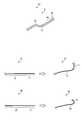
- FIG. 2is a schematic view showing the configuration of the endoscope 2.
- the endoscope 2includes an endoscope main body 2a, a first curved member 10, and a second curved member 20.
- the endoscope main body 2aincludes an image pickup device 64, an illumination unit, a treatment tool channel 74, an air supply / water supply channel 76, and a bending member channel 77, and the bending member channel 77 has a first curvature.
- the member 10 and the second curved member 20are inserted and removed.
- the first bending member 10has a bending portion 11 that is bendable and a flexible portion 12 that is connected to the base end side of the bending portion 11.
- the second bending member 20has a bending portion 21 that is bendable and a flexible portion 22 that is connected to the proximal end side of the bending portion 21.
- the bending diameter of the bending portion 11 of the first bending member 10is larger than the bending diameter of the bending portion 21 of the second bending member 20.
- FIG. 3is an enlarged schematic view of the first curved member 10.
- a plurality of curved pieces 13are connected to each other, and wires 14 are inserted in the upper, lower, left and right sides of the connected curved pieces 13.
- the flexible portion 12is composed of a tube with a flexible lumen 15, and a wire 14 is inserted into the lumen 15.
- the second curved member 20has the same configuration as the first curved member 10, but the length r1 of the curved portion of the first curved member 10 is longer than the length of the curved portion 21 of the second curved member. As a result, the bending diameter becomes large.
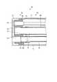
- FIG. 4is a cross-sectional view of the insertion portion 6 of the endoscope 2.
- the tip portion 6a of the tip portion 6a located on the tip end side of the insertion portion 6 of the endoscope 2is fitted with the tip portion 6a by the tip cover 61.
- the tip cover 61is provided with an observation window 63, an illumination window 75 of the illumination unit (see FIG. 5), an opening for air supply / water supply, and an opening 66 forming a treatment tool channel 74.
- An imaging device 64 for imaging the inside of the subjectis inserted in the proximal end side of the observation window 63.
- an air supply / water supply hole, a treatment tool channel 74, and the likeare provided so as to correspond to an opening for air supply / water supply and an opening 66 constituting the treatment tool channel 74, respectively.
- the tip block 62is arranged.
- the tip block 62is also provided with a curved member insertion hole 65.
- a treatment tool insertion pipe 68is provided at the rear end of the treatment tool channel 74 in the tip block 62, and the treatment tool insertion tube 70 is connected to the treatment tool insertion pipe 68.
- a curved member insertion pipe 67is provided at the rear end of the curved member insertion hole 65, and the curved member insertion tube 69 is connected to the curved member insertion pipe 67.
- the treatment tool channel 74 including the opening 66, the treatment tool insertion pipe 68, and the treatment tool insertion tube 70is a channel that opens at both ends, and is composed of a curved member insertion hole 65, a curved member insertion pipe 67, and a curved member insertion tube 69.
- the curved member channel 77is a channel that opens on the proximal end side and does not open on the distal end side.
- FIG. 5is a front view of the tip portion 6a of the endoscope 2.
- the curved member channel 77is arranged at the center of the insertion portion 6 of the endoscope main body 2a in the axial direction, and the imaging device 64 (observation window) is arranged around the curved member channel 77.
- an illumination unitillumination window 75
- a treatment tool channel 74treatment tool channel 74
- an air supply / water supply channel 76are provided.
- FIG. 6is a schematic view for explaining the operation method of the endoscope 2, and a case where the large intestine lb is treated with an endoscope will be described as an example.
- the first bending member 10for example, a member having a curved portion 11 having a length of about 135 mm is used, and for the second bending member 20, for example, a member having a bending portion 21 having a length of about 55 mm is used. used.
- An endoscope having a curved portion having a length of about 135 mmis conventionally used for large intestine observation, and an endoscope having a curved portion having a length of about 55 mm is used for endoscopic submucosal peeling. It is used for.
- the first bending member 10 having a long bending length of the bending portion 11is inserted into the bending member channel 77 of the insertion portion 6 of the endoscope 2, and FIG. 6B ),
- the insertion portion 6 into which the first bending member 10 is insertedis inserted into the large intestine lb.
- the curved portion 11 of the first bending member 10is curved so as to follow the shape of the large intestine lb, and is inserted while performing advancing / retreating and twisting operations integrally with the endoscope main body 2a. ..
- the cover curved portion 6bis also formed by inserting the first curved member 10 having a curved diameter close to the diameter of the curved portion of the large intestine and bending the curved portion 11. It is curved in the same manner as the curved portion 11, and the insertion portion 6 can be easily inserted.
- the observation diagnosis of the lesion Pis performed.
- the first bending member 10is pulled out from the bending member channel 77 of the insertion portion 6 (see FIG. 6D).
- the second bending member 20 having a short bending length of the bending portion 11is connected to the bending member channel 77 of the insertion portion 6. Is inserted (see FIG. 6 (f)).
- the tip portion 6a of the insertion portion 6is located in the vicinity of the lesion P, and the lesion is observed by the imaging device 64. , There is no risk of losing sight of lesion P.
- the bending operation of the bending portion 21 of the second bending member 20is performed to bring the treatment tool closer to the lesion P.
- Treatment of lesion P with a treatment toolfor example, local injection, peri-incision, incision detachment, suturing and the like.
- a treatment toolfor example, local injection, peri-incision, incision detachment, suturing and the like.
- the lumen diameter of the large intestine lbis as narrow as about 60 mm on average. It becomes difficult to approach the lesion P with the tip 6a.
- the second curved member 20 having a short curved lengthis used, as shown in FIG.
- the curved portion 21is curved until the tip portion 6a is inverted to treat the lesion P, or as shown in FIG. 8 (b), the lesion P is the back of the fold.
- the use of the second curved member 20 having a short curved lengthfacilitates the approach to the lesion P and facilitates the treatment. If it is difficult to approach the lesion P even with the second curved member 20 having a short curved length, a third curved member having a shorter curved length or an intermediate between the first curved member 10 and the second curved member 20.
- the treatmentmay be performed using a fourth curved member having a curved length of.
- the insertion portion 6 of the endoscope 2is removed from the subject together with the second curved member 20 (see FIG. 6 (h)).
- the second bending member 20is pulled out from the bending member channel 77.
- the endoscope main body 2ais discarded, and the first curved member 10 and the second curved member 20 can be reused in the next procedure after cleaning.
- the long-curved first curved member 10is used for insertion, the short-curved second curved member 20 is inserted into the curved member channel 77 for treatment, and the cover curvature of the insertion portion 6 is performed.
- the portion 6bBy bending the portion 6b, it is possible to provide the endoscope 2 having an excellent balance between insertability and therapeutic property.
- the risk of infectionis reduced by making the endoscope body 2a that comes into contact with the subject disposable and reusing the first curved member 10 and the second curved member 20 that can be inserted into and removed from the endoscope body 2a. At the same time, it is possible to suppress an increase in cost.
- the lesion Pis observed by the imaging device 64 when the first curved member 10 is inserted and removed, it is easy to approach the lesion P after the insertion of the second curved member 20. Become.
- the lesion Pis constantly observed, it is possible to quickly respond to unexpected bleeding or the like.
- the image pickup apparatus 64is fixed to the endoscope main body 2a and is discarded together with the endoscope main body 2a after the operation, but is reused as being removable from the endoscope main body 2a. May be good.
- FIG. 9is a schematic view illustrating a procedure using an endoscope according to a second embodiment of the present invention, and a case where the stomach S is treated with an endoscope will be described as an example.
- the first bending member 10for example, a member having a curved portion 11 having a length of about 70 mm is used
- the second bending member 20for example, a member having a bending portion 21 having a length of about 105 mm is used. used.
- the first bending member 10 having a short bending length of the bending portion 11is inserted into the bending member channel 77 of the insertion portion 6 of the endoscope 2, and the first bending member 10 is inserted into the insertion.
- Part 6is inserted into the stomach S.
- an observation diagnosis of the lesion Pis performed, and after the observation diagnosis, the first curved member 10 is pulled out from the insertion portion 6.
- the second bending member 20 having a long bending length of the bending portion 11is inserted into the bending member channel 77 of the insertion portion 6 of the endoscope 2.
- the curved portion 21 of the second curved member 20is curved to treat the lesion P with the treatment tool.
- the insertion portion 6 into which the second bending member 20 having a long bending length shown by the dotted line is insertedhas the first one having a shorter bending length shown by the solid line.
- the approach to the lesion P in the tangential direction of the stomach wallbecomes easier than that of the curved member 10.
- the endoscope system and the method of operating the endoscope according to the present inventioncan be suitably used for an endoscope having excellent insertability and therapeutic property.
Landscapes
- Health & Medical Sciences (AREA)
- Life Sciences & Earth Sciences (AREA)
- Surgery (AREA)
- Nuclear Medicine, Radiotherapy & Molecular Imaging (AREA)
- Biomedical Technology (AREA)
- Optics & Photonics (AREA)
- Pathology (AREA)
- Radiology & Medical Imaging (AREA)
- Biophysics (AREA)
- Engineering & Computer Science (AREA)
- Physics & Mathematics (AREA)
- Heart & Thoracic Surgery (AREA)
- Medical Informatics (AREA)
- Molecular Biology (AREA)
- Animal Behavior & Ethology (AREA)
- General Health & Medical Sciences (AREA)
- Public Health (AREA)
- Veterinary Medicine (AREA)
- Endoscopes (AREA)
Abstract
Description
Translated fromJapanese本発明は、内視鏡システム、および内視鏡の操作方法に関する。The present invention relates to an endoscope system and a method of operating an endoscope.
従来、内視鏡は、挿入部を患者等の被検体内に挿入することによって、撮像装置による被検体内の画像データの取得や、処置具等による治療を行っている。内視鏡の挿入部の湾曲部には、複数の湾曲駒等を連結して構成され、湾曲駒の内面に配置したワイヤの操作により湾曲可能とした湾曲管が設けられ、湾曲管を湾曲することで視野の変更や、被検体の湾曲形状に応じた挿入を可能としている。Conventionally, an endoscope inserts an insertion part into a subject such as a patient to acquire image data in the subject by an imaging device and to perform treatment with a treatment tool or the like. The curved portion of the insertion portion of the endoscope is configured by connecting a plurality of curved pieces and the like, and a curved tube that can be bent by operating a wire arranged on the inner surface of the curved piece is provided to bend the curved tube. It is possible to change the field of view and insert it according to the curved shape of the subject.
内視鏡は、湾曲部の湾曲径が異なるものを使用用途に応じて使い分けされており、例えば、大きな屈曲部を有する大腸等の挿入には湾曲径が大きいものが好ましく、病変の治療には湾曲径の小さい内視鏡が好ましく使用される。湾曲径が異なる内視鏡を使用する場合、内視鏡を観察部位まで挿入した後、体内から内視鏡を引き抜き、治療に好ましい湾曲径の内視鏡を再度挿入して治療を行っている(例えば、特許文献1参照)。Endoscopes with different curved diameters are used according to the intended use. For example, an endoscope having a large curved diameter is preferable for inserting a large intestine or the like having a large curved portion, and for treating lesions. An endoscope with a small bending diameter is preferably used. When using endoscopes with different curvature diameters, after inserting the endoscope to the observation site, the endoscope is pulled out from the body, and the endoscope with a curvature diameter preferable for treatment is reinserted for treatment. (See, for example, Patent Document 1).
また、内視鏡は、内視鏡の挿入部にカバーを被せた状態で被検体内に挿入し、治療を行う技術も提案されている(例えば、特許文献2および3参照)。Further, a technique has been proposed in which an endoscope is inserted into a subject with a cover on the insertion portion of the endoscope to perform treatment (see, for example,
特許文献1の技術では、撮像部を備えた内視鏡を一旦引き抜くため、観察位置が保持できず、病変を見失う場合があった。In the technique of
本発明は、上記に鑑みてなされたものであって、挿入性および治療性に優れる内視鏡システムおよび内視鏡の操作方法を提供することを目的とする。The present invention has been made in view of the above, and an object of the present invention is to provide an endoscope system having excellent insertability and therapeutic ability and a method of operating the endoscope.
上述した課題を解決し、目的を達成するために、本発明に係る内視鏡システムは、撮像部と、先端側に湾曲部を有する湾曲部材と、前記湾曲部材を挿抜できるチャンネルと、を有する内視鏡本体を備える。In order to solve the above-mentioned problems and achieve the object, the endoscope system according to the present invention has an imaging unit, a curved member having a curved portion on the tip side, and a channel into which the curved member can be inserted and removed. It is equipped with an endoscope body.
本発明によれば、湾曲径の異なる第1の湾曲部材および第2の内視鏡湾曲部材を目的に応じて使い分けすることにより、挿入性および治療性にも優れる内視鏡システム、および内視鏡の操作方法を提供することが可能となる。According to the present invention, by properly using the first bending member and the second endoscope bending member having different bending diameters according to the purpose, an endoscope system having excellent insertability and therapeutic ability, and endoscopy. It becomes possible to provide a method of operating a mirror.
以下、本発明を実施するための形態(以下、「実施の形態」という)について説明する。また、この実施の形態により本発明が限定されるものではない。さらに、以下の説明において参照する各図は、本発明の内容を理解でき得る程度に形状、大きさ、および位置関係を概略的に示してあるに過ぎない。すなわち、本発明は、各図で例示された形状、大きさおよび位置関係のみに限定されるものではない。さらにまた、図面の相互間においても、互いの寸法や比率が異なる部分が含まれている。Hereinafter, a mode for carrying out the present invention (hereinafter referred to as “a mode”) will be described. Further, the present invention is not limited to this embodiment. Furthermore, each of the figures referred to in the following description merely schematically shows the shape, size, and positional relationship to the extent that the contents of the present invention can be understood. That is, the present invention is not limited to the shape, size, and positional relationship exemplified in each figure. Furthermore, there are parts in which the dimensions and ratios of the drawings are different from each other.
(実施の形態1)
図1は、本発明の実施の形態1にかかる内視鏡システム100の全体構成を模式的に示す図である。図1に示すように、本実施の形態にかかる内視鏡システム1は、被検体内に導入され、被検体の体内を撮像して被検体内の画像信号を生成する内視鏡2と、内視鏡2が撮像した画像信号に所定の画像処理を施すとともに内視鏡システム1の各部を制御する情報処理装置3と、内視鏡2の照明光を生成する光源装置4と、情報処理装置3による画像処理後の画像信号を画像表示する表示装置5と、送気送水吸引を行う流体制御装置9と、を備える。(Embodiment 1)
FIG. 1 is a diagram schematically showing the overall configuration of the endoscope system 100 according to the first embodiment of the present invention. As shown in FIG. 1, the
内視鏡2は、被検体内に挿入される挿入部6と、挿入部6の基端部側であって術者が把持する操作部7と、操作部7から延伸する可撓性のユニバーサルコード8と、から構成されている。The
挿入部6は、照明ファイバからなるライトガイド、電気ケーブルまたは光ファイバ等を用いて実現される。挿入部6は、硬質の先端部6aと、湾曲自在なカバー湾曲部6bと、カバー湾曲部6bの基端側に設けられた可撓性を有する可撓部6cと、を有する。先端部6aには、照明レンズを経由して被検体内を照明する一対の照明部、被検体内を撮像する撮像装置64、処置具チャンネル74、送気送水チャンネル76、および後述する第1の湾曲部材(第1の内視鏡駆動部)10および第2の湾曲部材(第2の内視鏡駆動部)20を挿抜する湾曲部材用チャンネル77が設けられている(図4および図5参照)。The
操作部7は、後述する第1の湾曲部材10および第2の湾曲部材20を上下方向および左右方向に湾曲させる湾曲ノブ7aと、被検体の体腔内に生体鉗子、レーザメス等の処置具が挿入される処置具挿入部7bと、情報処理装置3、光源装置4、流体制御装置9等の周辺機器の操作を行う複数のスイッチ部7cと第1の湾曲部材10および第2の湾曲部材20が挿入される湾曲部材挿入部7dと、を有する。処置具挿入部7bから挿入された処置具は、内部に設けられた処置具用チャンネルを経て挿入部6の先端の開口部66から表出する(図4参照)。In the
ユニバーサルコード8は、照明ファイバからなるライトガイド、ケーブル等を用いて構成される。ユニバーサルコード8は、基端で分岐しており、分岐した一方の端部がコネクタ8aであり、他方の基端がコネクタ8bである。コネクタ8aは、情報処理装置3のコネクタに対して着脱自在である。コネクタ8aは、光源装置4に対して着脱自在である。ユニバーサルコード8は、光源装置4から出射された照明光を、コネクタ8b、および照明ファイバからなるライトガイドを経由して先端部6aに伝播する。また、ユニバーサルコード8は、撮像装置が撮像した画像信号を、ケーブルおよびコネクタ8aを経由して情報処理装置3に伝送する。The
情報処理装置3は、コネクタ8aから出力される画像信号に所定の画像処理を施すとともに、内視鏡システム1全体を制御する。The
光源装置4は、光を発する光源や、集光レンズ等を用いて構成される。光源装置4は、情報処理装置3の制御のもと、光源から光を発し、コネクタ8bおよびユニバーサルコード8の照明ファイバからなるライトガイドを経由して接続された内視鏡2へ、被写体である被検体内に対する照明光として供給する。The
表示装置5は、液晶または有機EL(Electro Luminescence)を用いた表示ディスプレイ等を用いて構成される。表示装置5は、映像ケーブル5aを経由して情報処理装置3によって所定の画像処理が施された画像を含む各種情報を表示する。これにより、術者は、表示装置5が表示する画像(体内画像)を見ながら内視鏡2を操作することにより、被検体内の所望の位置の観察および症状を判定することができる。The
次に、実施の形態1に係る内視鏡2の構造について詳細に説明する。図2は、内視鏡2の構成を示す概略図である。内視鏡2は、内視鏡本体2aと、第1の湾曲部材10と、第2の湾曲部材20と、を備える。内視鏡本体2aは、撮像装置64と、照明部と、処置具チャンネル74と、送気送水チャンネル76と、湾曲部材用チャンネル77と、を有し、湾曲部材用チャンネル77に第1の湾曲部材10および第2の湾曲部材20が挿抜される。Next, the structure of the
第1の湾曲部材10は、湾曲自在な湾曲部11と、湾曲部11の基端側に接続される可撓性を有する可撓部12と、を有する。第2の湾曲部材20は、湾曲自在な湾曲部21と、湾曲部21の基端側に接続される可撓性を有する可撓部22と、を有する。第1の湾曲部材10の湾曲部11の湾曲径は、第2の湾曲部材20の湾曲部21の湾曲径よりも大きくなっている。The
図3は、第1の湾曲部材10の拡大概略図である。湾曲部11は、複数の湾曲駒13が連接され、連接する湾曲駒13の上下左右には、ワイヤ14が挿通されている。可撓部12は、可撓性を有するルーメン15付きのチューブで構成され、ルーメン15内にワイヤ14が挿通されている。第2の湾曲部材20も第1の湾曲部材10と同様の構成を有するが、第1の湾曲部材10の湾曲部の長さr1が、第2の湾曲部材の湾曲部21の長さより長いことにより、湾曲径が大きくなる。FIG. 3 is an enlarged schematic view of the first
図4は、内視鏡2の挿入部6の断面図である。内視鏡2の挿入部6の先端側に位置する先端部6aは、先端カバー61によって先端部6aが外嵌されている。先端カバー61には、観察窓63、照明部の照明窓75(図5参照)、送気・送水用の開口部および処置具チャンネル74を構成する開口部66が設けられている。観察窓63の基端側には、被検体内を撮像する撮像装置64が挿嵌されている。また、先端カバー61の後方には、送気・送水用の開口部および処置具チャンネル74を構成する開口部66にそれぞれ対応するように、送気・送水孔および処置具チャンネル74などが設けられた先端ブロック62が配設されている。先端ブロック62には、湾曲部材挿通孔65も設けられている。FIG. 4 is a cross-sectional view of the
先端ブロック62における処置具チャンネル74の後端部には処置具挿通パイプ68が設けられており、処置具挿通パイプ68に処置具挿通チューブ70が接続されている。また、湾曲部材挿通孔65の後端部には湾曲部材挿通パイプ67が設けられており、湾曲部材挿通パイプ67に湾曲部材挿通チューブ69が接続されている。開口部66、処置具挿通パイプ68および処置具挿通チューブ70からなる処置具チャンネル74は、両端が開口するチャンネルであり、湾曲部材挿通孔65、湾曲部材挿通パイプ67および湾曲部材挿通チューブ69からなる湾曲部材用チャンネル77は、基端部側が開口し、先端側が開口しないチャンネルである。A treatment
図5は、内視鏡2の先端部6aの正面図である。図4および図5に示すように、湾曲部材用チャンネル77は、内視鏡本体2aの挿入部6の軸方向の中心に配置され、湾曲部材用チャンネル77の周囲に、撮像装置64(観察窓63)、照明部(照明窓75)、処置具チャンネル74および送気送水チャンネル76が設けられている。湾曲部材用チャンネル77を挿入部6の軸方向の中心に配置することにより、第1の湾曲部材10の湾曲部11および第2の湾曲部材20の湾曲部21の湾曲操作により、内視鏡本体2aの湾曲操作を容易に行うことができる。FIG. 5 is a front view of the
次に、実施の形態1に係る内視鏡2の操作方法について詳細に説明する。図6は、内視鏡2の操作方法を説明する概略図であり、大腸lbを内視鏡で処置する場合を例として説明する。ここで、第1の湾曲部材10は、例えば、湾曲部11の長さが135mm程度のものが使用され、第2の湾曲部材20は、例えば、湾曲部21の長さが55mm程度のものが使用される。135mm程度の長さの湾曲部を有する内視鏡は、従来大腸観察用途に使用されるものであり、55mm程度の長さの湾曲部を有する内視鏡は、内視鏡的粘膜下層はく離術に使用されるものである。Next, the operation method of the
まず、図6(a)に示すように、内視鏡2の挿入部6の湾曲部材用チャンネル77に、湾曲部11の湾曲長が長い第1の湾曲部材10を挿入し、図6(b)に示すように、第1の湾曲部材10を挿入した挿入部6を大腸lb内に挿入する。挿入部6の大腸への挿入は、第1の湾曲部材10の湾曲部11を大腸lbの形状に沿うように湾曲させて、内視鏡本体2aと一体として進退、捻り操作を行いながら挿入する。大腸lbは比較的大きな径で湾曲しているため、大腸の湾曲部の径に近似する湾曲径を有する第1の湾曲部材10を挿入し湾曲部11を湾曲させることにより、カバー湾曲部6bも湾曲部11と同様に湾曲し、挿入部6の挿入が容易となる。First, as shown in FIG. 6A, the first bending
図6(c)に示すように、挿入部6の先端部6aが被検体の目標部位、例えば病変Pまで挿入した後、病変Pの観察診断を行う。観察診断後、挿入部6の湾曲部材用チャンネル77から第1の湾曲部材10を引き抜く(図6(d)参照)。湾曲部材用チャンネル77から第1の湾曲部材10を引き抜いた後(図6(e)参照)、挿入部6の湾曲部材用チャンネル77に、湾曲部11の湾曲長が短い第2の湾曲部材20を挿入する(図6(f)参照)。第1の湾曲部材10の引き抜きと第2の湾曲部材20の挿入の際にも、挿入部6の先端部6aは病変Pの近傍に位置し、撮像装置64で病変を観察した状態であるため、病変Pを見失うおそれはない。As shown in FIG. 6C, after the
第2の湾曲部材20を湾曲部材用チャンネル77に挿入後(図6(g)参照)、第2の湾曲部材20の湾曲部21を湾曲操作して、処置具を病変Pに近接させた後、処置具により病変Pの治療、例えば、局注、周囲切開、切開剥離、縫合等を行う。湾曲長が長い第1の湾曲部材10を使用する場合、図7(A)に示すように、大腸lbの管腔径は平均で60mm程度と狭いため、脾湾曲部にある病変Pに対し、先端部6aを病変Pにアプローチするのが難しくなる。これに対し、湾曲長が短い第2の湾曲部材20を使用する場合、図7(B)に示すように、小回りが利くため、狭い管腔内でも病変Pに対しアプローチしやすく、処置も行いやすい。また、図8(A)に示すように、湾曲部21を先端部6aが反転するまで湾曲させて、病変Pを処置する場合や、図8(b)に示すように、病変Pが襞裏に存在する場合には、湾曲長が短い第2の湾曲部材20の使用により、病変Pに対しアプローチしやすく、処置が行いやすくなる。なお、湾曲長が短い第2の湾曲部材20でも病変Pにアプローチし難い場合は、より湾曲長が短い第3の湾曲部材や、第1の湾曲部材10と第2の湾曲部材20との中間の湾曲長の第4の湾曲部材を使用して治療を行ってもよい。After inserting the
治療の後、第2の湾曲部材20とともに内視鏡2の挿入部6を被検体内から抜去する(図6(h)参照)。被検体から抜去した後、湾曲部材用チャンネル77から第2の湾曲部材20を抜き取る。処置後、内視鏡本体2aは廃棄され、第1の湾曲部材10および第2の湾曲部材20は、洗浄後、次の手技で再利用することができる。After the treatment, the
実施の形態1では、挿入には長湾曲の第1の湾曲部材10を使用し、治療には短湾曲の第2の湾曲部材20を湾曲部材用チャンネル77に挿入し、挿入部6のカバー湾曲部6bを湾曲操作することにより、挿入性と治療性のバランスに優れた内視鏡2を提供することができる。また、被検体と接触する内視鏡本体2aを使い捨て可能とし、内視鏡本体2aに挿抜可能な第1の湾曲部材10および第2の湾曲部材20を再使用することで、感染リスクを軽減するとともに、コストの上昇を抑制することができる。In the first embodiment, the long-curved first
さらに、実施の形態1では、第1の湾曲部材10の挿抜の際、撮像装置64により病変Pを観察しているため、第2の湾曲部材20の挿入後の病変Pへのアプローチが容易となる。また、常に病変Pを観察しているため、予期せぬ出血等に対して迅速な対応が可能となる。さらにまた、鉗子で対象を掴んだ状態や、管腔内の状態保持のための送気操作中の湾曲部材の交換も可能となり、湾曲部材交換後に場を作り直す手間を削減することができる。Further, in the first embodiment, since the lesion P is observed by the
なお、上記の実施の形態1では、撮像装置64は内視鏡本体2aに固定され、術後、内視鏡本体2aとともに廃棄されるが、内視鏡本体2aから着脱可能として再使用してもよい。In the first embodiment described above, the
(実施の形態2)
図9は、本発明の実施の形態2に係る内視鏡を使用した処置を説明する概略図であり、胃Sを内視鏡で処置する場合を例として説明する。ここで、第1の湾曲部材10は、例えば、湾曲部11の長さが70mm程度のものが使用され、第2の湾曲部材20は、例えば、湾曲部21の長さが105mm程度のものが使用される。(Embodiment 2)
FIG. 9 is a schematic view illustrating a procedure using an endoscope according to a second embodiment of the present invention, and a case where the stomach S is treated with an endoscope will be described as an example. Here, as the first bending
実施の形態2では、内視鏡2の挿入部6の湾曲部材用チャンネル77に、湾曲部11の湾曲長が短い第1の湾曲部材10を挿入し、第1の湾曲部材10を挿入した挿入部6を胃S内に挿入する。挿入部6の先端部6aを病変Pまで挿入した後、病変Pの観察診断を行い、観察診断後、挿入部6から第1の湾曲部材10を引き抜く。湾曲部材用チャンネル77から第1の湾曲部材10を引き抜いた後、内視鏡2の挿入部6の湾曲部材用チャンネル77に、湾曲部11の湾曲長が長い第2の湾曲部材20を挿入し、第2の湾曲部材20の湾曲部21を湾曲操作して、処置具により病変Pの治療を行う。In the second embodiment, the first bending
例えば、小彎に病変Pがある場合、図9に示すように、点線で示す湾曲長が長い第2の湾曲部材20を挿入した挿入部6の方が、実線で示す湾曲長が短い第1の湾曲部材10よりも病変Pに対して胃壁の接線方向でのアプローチが容易となる。For example, when there is a lesion P in the lesser curvature, as shown in FIG. 9, the
本発明に係る内視鏡システムおよび内視鏡の操作方法は、挿入性および治療性に優れる内視鏡に好適に用いることができる。The endoscope system and the method of operating the endoscope according to the present invention can be suitably used for an endoscope having excellent insertability and therapeutic property.
1 内視鏡システム
2 内視鏡
2a 内視鏡本体
3 情報処理装置
4 光源装置
5 表示装置
6 挿入部
6a 先端部
6b カバー湾曲部
6c 可撓部
7 操作部
7a 湾曲ノブ
7b 処置具挿入部
7c スイッチ部
7d 湾曲部材挿入部
8 ユニバーサルコード
8a、8b コネクタ
10 第1の湾曲部材
11、21 湾曲部
12、22 可撓部
20 第2の湾曲部材
61 先端カバー
62 先端ブロック
63 観察窓
64 撮像装置
65 湾曲部材挿通孔
66 開口部
67 湾曲部材挿通パイプ
68 処置具挿通パイプ
69 湾曲部材挿通チューブ
70 処置具挿通チューブ
74 処置具チャンネル
75 照明窓
76 送気送水チャンネル
77 湾曲部材用チャンネル1
Claims (10)
Translated fromJapanese前記第1の湾曲部材を挿入した内視鏡の挿入部を、被検体の目標部位まで挿入し、
前記撮像部により病変を観察診断後、前記第1の湾曲部材を前記先チャンネルから抜去し、
前記チャンネルに、第2の湾曲部材を挿入する内視鏡の操作方法。A first curved member is inserted into the channel of the endoscope main body having an imaging unit, a curved member having a curved portion on the tip side, and a channel through which the curved member can be inserted / removed.
The insertion portion of the endoscope into which the first curved member is inserted is inserted to the target site of the subject, and the insertion portion is inserted.
After observing and diagnosing the lesion with the imaging unit, the first curved member is removed from the tip channel.
A method of operating an endoscope in which a second curved member is inserted into the channel.
Priority Applications (1)
| Application Number | Priority Date | Filing Date | Title |
|---|---|---|---|
| PCT/JP2020/008978WO2021176570A1 (en) | 2020-03-03 | 2020-03-03 | Endoscope system and method for operating endoscope |
Applications Claiming Priority (1)
| Application Number | Priority Date | Filing Date | Title |
|---|---|---|---|
| PCT/JP2020/008978WO2021176570A1 (en) | 2020-03-03 | 2020-03-03 | Endoscope system and method for operating endoscope |
Publications (1)
| Publication Number | Publication Date |
|---|---|
| WO2021176570A1true WO2021176570A1 (en) | 2021-09-10 |
Family
ID=77613155
Family Applications (1)
| Application Number | Title | Priority Date | Filing Date |
|---|---|---|---|
| PCT/JP2020/008978CeasedWO2021176570A1 (en) | 2020-03-03 | 2020-03-03 | Endoscope system and method for operating endoscope |
Country Status (1)
| Country | Link |
|---|---|
| WO (1) | WO2021176570A1 (en) |
Cited By (1)
| Publication number | Priority date | Publication date | Assignee | Title |
|---|---|---|---|---|
| US20220304552A1 (en)* | 2021-03-29 | 2022-09-29 | Fujifilm Corporation | Endoscope |
Citations (5)
| Publication number | Priority date | Publication date | Assignee | Title |
|---|---|---|---|---|
| JPS6321066A (en)* | 1986-07-16 | 1988-01-28 | オリンパス光学工業株式会社 | Medical tube |
| JPH0666606U (en)* | 1993-02-26 | 1994-09-20 | オリンパス光学工業株式会社 | Endoscope with channel cover system |
| JPH07116106A (en)* | 1993-10-22 | 1995-05-09 | Olympus Optical Co Ltd | Cover-type endoscope |
| JP2005279125A (en)* | 2004-03-31 | 2005-10-13 | Pentax Corp | The tip of the electronic endoscope |
| JP2010220951A (en)* | 2009-03-25 | 2010-10-07 | Olympus Medical Systems Corp | Cover-type treatment endoscope and endoscope cover |
- 2020
- 2020-03-03WOPCT/JP2020/008978patent/WO2021176570A1/ennot_activeCeased
Patent Citations (5)
| Publication number | Priority date | Publication date | Assignee | Title |
|---|---|---|---|---|
| JPS6321066A (en)* | 1986-07-16 | 1988-01-28 | オリンパス光学工業株式会社 | Medical tube |
| JPH0666606U (en)* | 1993-02-26 | 1994-09-20 | オリンパス光学工業株式会社 | Endoscope with channel cover system |
| JPH07116106A (en)* | 1993-10-22 | 1995-05-09 | Olympus Optical Co Ltd | Cover-type endoscope |
| JP2005279125A (en)* | 2004-03-31 | 2005-10-13 | Pentax Corp | The tip of the electronic endoscope |
| JP2010220951A (en)* | 2009-03-25 | 2010-10-07 | Olympus Medical Systems Corp | Cover-type treatment endoscope and endoscope cover |
Cited By (2)
| Publication number | Priority date | Publication date | Assignee | Title |
|---|---|---|---|---|
| US20220304552A1 (en)* | 2021-03-29 | 2022-09-29 | Fujifilm Corporation | Endoscope |
| US12167832B2 (en)* | 2021-03-29 | 2024-12-17 | Fujifilm Corporation | Endoscope having a treatment tool outlet port |
Similar Documents
| Publication | Publication Date | Title |
|---|---|---|
| CN114343544B (en) | Endoscope with movable front end | |
| KR101556881B1 (en) | Endoscope | |
| US6855107B2 (en) | Method for insertion of an endoscope into the colon | |
| JP4416990B2 (en) | System for operating a device in vivo | |
| US8216128B2 (en) | Medical system with a biological information acquiring apparatus and a manipulation information acquiring apparatus | |
| JP2013526348A (en) | Method and apparatus for imaging the internal surface of a body cavity | |
| US20120226223A1 (en) | Procedure | |
| CN215128274U (en) | Steering control mechanism, endoscope, and medical examination device | |
| JP2012070934A (en) | Endoscope apparatus | |
| KR101801393B1 (en) | Surgical endoscope and process for exchanging surgical tools in a surgical endoscope | |
| CN113613542A (en) | Disposable device with integrated vision capabilities | |
| JP2000245689A (en) | Auxiliary tool for endoscope insertion | |
| US20250248588A1 (en) | Systems and methods for medical device intubation | |
| CN118830798A (en) | Front end structure and endoscope | |
| JP5390146B2 (en) | Auxiliary tool and endoscope system using the same | |
| WO2021176570A1 (en) | Endoscope system and method for operating endoscope | |
| JP5030449B2 (en) | Endoscope insertion aid | |
| JP4441232B2 (en) | External channel and endoscope apparatus provided with the same | |
| US20090227866A1 (en) | Ultrasound endoscopic intraluminal organ treatment method | |
| JP2001061760A (en) | Cover sheath type rigid endoscope | |
| JP5557237B2 (en) | Small diameter endoscope and small diameter endoscope set | |
| JP3014213B2 (en) | Oblique endoscope | |
| JP2000014626A (en) | Endoscope | |
| KR101620831B1 (en) | Surgical instrument | |
| JP5384894B2 (en) | Adapter and endoscope system using the adapter |
Legal Events
| Date | Code | Title | Description |
|---|---|---|---|
| 121 | Ep: the epo has been informed by wipo that ep was designated in this application | Ref document number:20923451 Country of ref document:EP Kind code of ref document:A1 | |
| NENP | Non-entry into the national phase | Ref country code:DE | |
| 122 | Ep: pct application non-entry in european phase | Ref document number:20923451 Country of ref document:EP Kind code of ref document:A1 | |
| NENP | Non-entry into the national phase | Ref country code:JP |