WO2021174862A1 - Solar tower and trough combined power generation system - Google Patents
Solar tower and trough combined power generation systemDownload PDFInfo
- Publication number
- WO2021174862A1 WO2021174862A1PCT/CN2020/121428CN2020121428WWO2021174862A1WO 2021174862 A1WO2021174862 A1WO 2021174862A1CN 2020121428 WCN2020121428 WCN 2020121428WWO 2021174862 A1WO2021174862 A1WO 2021174862A1
- Authority
- WO
- WIPO (PCT)
- Prior art keywords
- inlet
- outlet
- heat
- heat transfer
- storage tank
- Prior art date
- Legal status (The legal status is an assumption and is not a legal conclusion. Google has not performed a legal analysis and makes no representation as to the accuracy of the status listed.)
- Ceased
Links
Images


Classifications
- F—MECHANICAL ENGINEERING; LIGHTING; HEATING; WEAPONS; BLASTING
- F03—MACHINES OR ENGINES FOR LIQUIDS; WIND, SPRING, OR WEIGHT MOTORS; PRODUCING MECHANICAL POWER OR A REACTIVE PROPULSIVE THRUST, NOT OTHERWISE PROVIDED FOR
- F03G—SPRING, WEIGHT, INERTIA OR LIKE MOTORS; MECHANICAL-POWER PRODUCING DEVICES OR MECHANISMS, NOT OTHERWISE PROVIDED FOR OR USING ENERGY SOURCES NOT OTHERWISE PROVIDED FOR
- F03G6/00—Devices for producing mechanical power from solar energy
- F03G6/06—Devices for producing mechanical power from solar energy with solar energy concentrating means
- F03G6/065—Devices for producing mechanical power from solar energy with solar energy concentrating means having a Rankine cycle
- F03G6/067—Binary cycle plants where the fluid from the solar collector heats the working fluid via a heat exchanger
- Y—GENERAL TAGGING OF NEW TECHNOLOGICAL DEVELOPMENTS; GENERAL TAGGING OF CROSS-SECTIONAL TECHNOLOGIES SPANNING OVER SEVERAL SECTIONS OF THE IPC; TECHNICAL SUBJECTS COVERED BY FORMER USPC CROSS-REFERENCE ART COLLECTIONS [XRACs] AND DIGESTS
- Y02—TECHNOLOGIES OR APPLICATIONS FOR MITIGATION OR ADAPTATION AGAINST CLIMATE CHANGE
- Y02E—REDUCTION OF GREENHOUSE GAS [GHG] EMISSIONS, RELATED TO ENERGY GENERATION, TRANSMISSION OR DISTRIBUTION
- Y02E10/00—Energy generation through renewable energy sources
- Y02E10/40—Solar thermal energy, e.g. solar towers
- Y02E10/46—Conversion of thermal power into mechanical power, e.g. Rankine, Stirling or solar thermal engines
Definitions
- the inventionrelates to the technical field of solar photothermal power generation, in particular to a solar tower and trough combined power generation system.
- Solar thermal power generationusually uses heat collectors to condense and collect heat to generate electricity, and use mirrors to condense sunlight to a receiver for absorbing solar energy, generate heat and transfer it to synthetic oil, molten salt, or air. fluid. Then, the heat transfer fluid directly or indirectly provides heat to the power cycle system.
- solar thermal power generationhas attracted more and more attention due to its high energy density, stable power generation, good grid compatibility, and easy integration with existing thermal power plants.
- the existing solar thermal power plantsall adopt a single collector structure: solar trough power generation or solar tower power generation.
- Solar trough-type power generation technologyuses a trough-shaped parabolic reflector.
- the reflectoruses a single-axis tracking method to track the sun during the day.
- the reflectorreflects the sunlight and concentrates it on the heating tube located at the focal line.
- the heat transfer fluidflows through the heating tube and absorbs the heat generated by the concentrated sunlight, and supplies it to the power generation system.
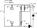
- the structure diagram of the existing solar trough-type power generation systemis shown in Figure 1.
- the circulation loop of the heat transfer fluidis: after the heat transfer fluid is heated by the trough collector 11, a part of it passes through the superheater 22 and preheated in turn
- the heat exchanger 21exchanges heat with the Rankine cycle passing through the heat exchanger 22 and the preheater 21 and then flows back to the trough collector 11, and the other part passes through the reheater 23 and exchanges heat with the Rankine cycle passing through the reheater 23 Then it flows back to the trough collector 11.
- Solar tower power generation technologyis a solar power generation technology that uses a receiver located on the top of a tall tower to receive concentrated sunlight. It uses a large number of movable solar mirrors (called heliostats), and each heliostat is equipped with a tracking mechanism to accurately reflect the sunlight to the receiver on the top of the tower in real time.
- the tracking mechanismis a dual-axis tracking (from east to west, up and down) to track the sun.
- the receiverabsorbs concentrated solar radiation to convert solar energy into heat, which is then transferred to the thermal cycle system by the heat transfer fluid for power generation.
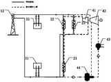
- the structure diagram of the existing solar tower power generation systemis shown in Figure 2.
- the circulation loop of the heat transfer fluidis: after the heat transfer fluid is heated by the tower collector 12, a part of it passes through the superheater 22 and preheated in turn
- the heat exchanger 21exchanges heat with the Rankine cycle passing through the heat exchanger 22 and the preheater 21 and then flows back to the tower collector 12, and the other part passes through the reheater 23 and exchanges heat with the Rankine cycle passing through the reheater 23 Then flow back to the tower collector 12.
- Solar trough power generation technologyis the most mature and commercialized technology, but it has the following shortcomings: the concentration ratio is relatively small, the heat collection temperature of the receiver is relatively low, and the efficiency of solar thermal power generation is relatively low.
- Solar tower power generation technologybecause the top of the tower can condense a large amount of energy when a large number of heliostats are used, and the receiver can reach a very high temperature, so it has the advantage of high efficiency of solar thermal power generation and can be applied on a large scale, but At the same time, it has the disadvantages of high investment cost, high system complexity, large heat exchange temperature difference of the heat absorber, and high energy consumption of the molten salt insulation system.
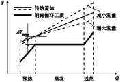
- the existing solar tower power generation technology and solar trough power generation technologyboth have a large temperature difference and large temperature difference between the heat transfer fluid and the Rankine cycle heat exchange process. Damage problem. This is because, for trough power generation and tower power generation technologies, during the heat exchange process between the heat transfer fluid and the Rankine cycle working fluid, as shown in Figure 3, the Rankine cycle working fluid has a phase change, while the heat transfer fluid does not Phase change, so there is a large heat transfer temperature difference in the heat transfer process, and the heat transfer The problem of greater damage.
- the heat transfer fluidcan only flow through each heat exchanger (preheater 21) at a constant mass flow rate. , Superheater 22 and reheater 23) to achieve heat exchange, as shown in Figure 4, in the case that the pinch temperature difference ⁇ T min is fixed, if the mass flow rate of the heat transfer fluid is increased to reduce the slope of the heat transfer fluid curve , While reducing the average heat transfer temperature difference in the evaporation section, it also increases the average heat transfer temperature difference in the preheating section; similarly, if the flow rate of the heat transfer fluid is reduced to increase the slope of the heat transfer fluid curve, it will decrease The average heat exchange temperature difference in the preheating section also increases the average heat exchange temperature difference in the evaporation section, so the large temperature difference and the large The problem of damage is always unavoidable.
- the purpose of the present inventionis to provide a solar tower and trough combined power generation system, which overcomes the large temperature difference and large temperature difference caused by the heat transfer fluid that can only flow through the heat exchangers at a constant mass flow rate in the prior art. The problem of damage.
- the present inventionadopts the following technical solutions:
- a solar tower and trough combined power generation systemincluding: a heat collection device and a heat exchange device;
- the heat collection deviceincludes: a trough type heat collector and a tower type heat collector;
- the heat exchange deviceincludes: a preheater, a superheater, and a reheater, and the preheater or the superheater is also combined with an evaporator;
- the heating pipe outlet of the trough collectoris connected to the heat transfer fluid inlet of the preheater through a first pipe; the heat transfer fluid outlet of the preheater is connected to the trough collector through a second pipe.
- the inlet of the heating pipe of the heateris connected;
- the heating pipe outlet of the tower collectoris connected to the heat transfer fluid inlet of the superheater and the heat transfer fluid inlet of the reheater through a third pipe; the heat transfer fluid outlet of the superheater and The heat transfer fluid outlet of the reheater is respectively connected to the heating pipe inlet of the tower collector through a fourth pipe.
- italso includes a heat storage device
- the heat storage deviceincludes: a low temperature heat storage tank, a medium temperature heat storage tank, and a high temperature heat storage tank;
- the inlet of the low-temperature heat storage tankis connected to the second pipeline through a first valve, and the outlet of the low-temperature heat storage tank is connected to the second pipeline through a second valve;
- the inlet of the high temperature heat storage tankis connected to the third pipeline through a third valve, and the outlet of the high temperature heat storage tank is connected to the third pipeline through a fourth valve;
- the first inlet of the medium temperature heat storage tankis connected to the first pipe through a fifth valve; the first outlet of the medium temperature heat storage tank is connected to the first pipe through a sixth valve; the medium temperature heat storage tank The second inlet of the heat tank is connected to the fourth pipe through a fifth valve; the second outlet of the medium-temperature heat storage tank is connected to the fourth pipe through a sixth valve.
- the steam turbinealso includes a steam turbine, and the steam turbine includes a high-pressure cylinder and a medium and low-pressure cylinder;
- the working fluid outlet of the superheateris connected to the working fluid inlet of the high-pressure cylinder;
- the working fluid outlet of the high-pressure cylinderis connected to the working fluid inlet of the reheater;
- the working fluid outlet of the reheateris connected with the working fluid inlet of the medium and low pressure cylinder;
- the first working fluid outlet of the middle and low pressure cylinderis connected to the inlet of the deaerator, and the second working fluid outlet of the middle and low pressure cylinder is connected to the inlet of the deaerator through a condenser;
- the outlet of the deaeratoris connected with the working fluid inlet of the preheater
- the working fluid outlet of the preheateris connected with the working fluid inlet of the superheater.
- the design value of the outlet temperature of the heat transfer fluid of the trough collectoris not equal to the design value of the inlet temperature of the heat transfer fluid of the tower collector.
- the heat transfer fluid flowing through the heat collection device and the heat exchange deviceincludes: synthetic oil, molten salt or air; the Rankine cycle working fluid flowing through the heat exchange device includes: water, CO2 or organic working fluid.
- the present inventionalso proposes another solar tower and trough combined power generation system, including: a heat collection device, a heat storage device and a heat exchange device;
- the heat collection deviceincludes: a trough type heat collector and a tower type heat collector;
- the heat storage deviceincludes: a low temperature heat storage tank, a medium temperature heat storage tank, and a high temperature heat storage tank;
- the heat exchange deviceincludes: a preheater, a superheater, and a reheater, and the preheater or the superheater is also combined with an evaporator;
- the outlet of the heating pipe of the trough collectoris connected to the first inlet of the medium-temperature heat storage tank through a first pipe; the first outlet of the medium-temperature heat storage tank is connected to the preheater through a second pipe
- the heat transfer fluid inlet of the preheateris connected; the heat transfer fluid outlet of the preheater is connected to the inlet of the low temperature heat storage tank through a third pipe; the outlet of the low temperature heat storage tank is connected to the tank through a fourth pipe
- the inlet of the heating tube of the heat collectoris connected;
- the outlet of the heating pipe of the tower collectoris connected to the inlet of the high temperature heat storage tank through a fifth pipe; the outlet of the high temperature heat storage tank is connected to the heat transfer fluid inlet of the superheater through a sixth pipe Are respectively connected to the heat transfer fluid inlet of the reheater; the heat transfer fluid outlet of the superheater and the heat transfer fluid outlet of the reheater respectively pass through the seventh pipe and the second heat storage tank
- the inletis connected; the second outlet of the medium-temperature heat storage tank is connected to the heating tube inlet of the tower collector through an eighth pipe.
- the steam turbinealso includes a steam turbine, and the steam turbine includes a high-pressure cylinder and a medium and low-pressure cylinder;
- the working fluid outlet of the superheateris connected to the working fluid inlet of the high-pressure cylinder;
- the working fluid outlet of the high-pressure cylinderis connected to the working fluid inlet of the reheater;
- the working fluid outlet of the reheateris connected with the working fluid inlet of the medium and low pressure cylinder;
- the first working fluid outlet of the middle and low pressure cylinderis connected to the inlet of the deaerator, and the second working fluid outlet of the middle and low pressure cylinder is connected to the inlet of the deaerator through a condenser;
- the outlet of the deaeratoris connected with the working fluid inlet of the preheater
- the working fluid outlet of the preheateris connected with the working fluid inlet of the superheater.
- the design value of the outlet temperature of the heat transfer fluid of the trough collectoris not equal to the design value of the inlet temperature of the heat transfer fluid of the tower collector.
- the heat transfer fluid flowing through the heat collection device and the heat exchange deviceincludes: synthetic oil, molten salt or air; the Rankine cycle working fluid flowing through the heat exchange device includes: water, CO2 or organic working fluid.
- the embodiment of the present inventionuses both a tower collector and a trough collector.
- the trough collectoris used to collect the heat at a lower temperature
- the tower collectoris used to collect the heat at a higher temperature, so that the tower
- the trough collector and the trough collectorcan work in their respective optimal operating temperature ranges, which is beneficial to improve the efficiency of the system.
- the addition of the trough collectorcan also increase the utilization rate of the tower mirror field and reduce the system cost. .
- the embodiment of the present inventionuses tower collectors and trough collectors to realize the segmented heating of the Rankine cycle working fluid; based on the segmented heating method, the mass flow of the heat transfer fluid in each heat exchanger It can be adjusted separately according to the needs, so as to reduce the heat exchange temperature difference of each heat exchanger and reduce the heat exchange process Loss and improve the power generation efficiency of power plants.
- Figure 1is a structural diagram of an existing solar trough-type power generation system
- Figure 2is a structural diagram of an existing solar tower power generation system
- Figure 3is a schematic diagram of heat transfer of an existing tower power generation system and a trough power generation system
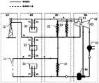
- Fig. 5is a structural diagram of a solar tower and trough combined power generation system provided by the first embodiment of the present invention
- FIG. 6is a schematic diagram of heat transfer when the mass flow rate of the heat transfer fluid is changed according to an embodiment of the present invention
- FIG. 7is another schematic diagram of heat transfer when the mass flow rate of the heat transfer fluid is changed according to an embodiment of the present invention.
- Fig. 8is a structural diagram of a solar tower-tank combined power generation system provided by the second embodiment of the present invention.
- Heat collector 10trough collector 11, tower collector 12;
- Heat exchange device 20preheater 21, superheater 22, reheater 23;
- Heat storage device 30low temperature heat storage tank 31, medium temperature heat storage tank 32, high temperature heat storage tank 33;
- Steam turbine 40high pressure cylinder 41, medium and low pressure cylinder 42, condenser 43, deaerator 44.
- the core idea of the present inventionis: by using multi-stage heat storage to achieve multiple heat source temperatures and multiple heat transfer fluid flow rates, to achieve segmented heating of the preheating section, evaporation section, and overheating section, thereby solving the problem of heat transfer fluid and Rankine cycle.
- the large temperature difference and large Damage problemis: by using multi-stage heat storage to achieve multiple heat source temperatures and multiple heat transfer fluid flow rates, to achieve segmented heating of the preheating section, evaporation section, and overheating section, thereby solving the problem of heat transfer fluid and Rankine cycle.
- an embodiment of the present inventionprovides a solar tower and trough combined power generation system, including: a heat collection device 10 and a heat exchange device 20;
- the heat collection device 10includes: a trough type heat collector 11 and a tower type heat collector 12.
- the heat exchange device 20includes: a preheater 21, a superheater 22, and a reheater 23, and the preheater 21 or the superheater 22 also has an evaporator function.
- the heating pipe outlet of the trough collector 11is connected to the heat transfer fluid inlet of the preheater 21 through the first pipe; the heat transfer fluid outlet of the preheater 21 is heated by the trough heat collector 11 through the second pipe The pipe inlet is connected.
- the heat transfer fluid flowing out of the heating tube of the trough collector 11first flows into the preheater 21 through the first pipe, and exchanges heat with the Rankine cycle working fluid flowing through the preheater 21. Then the second pipe enters into the heating tube of the trough collector 11 to absorb heat, thereby forming a first heat transfer fluid circulation loop.
- the outlet of the heating tube of the tower collector 12is respectively connected to the heat transfer fluid inlet of the superheater 22 and the heat transfer fluid inlet of the reheater 23 through a third pipe; the heat transfer fluid outlet of the superheater 22 and the reheater 23 The outlets of the heat transfer fluid are respectively connected to the inlets of the heating pipes of the tower collector 12 through the fourth pipe.
- the heat transfer fluid flowing out of the heating tube of the tower collector 12first passes through the third pipe.
- the reheater 23exchanges heat with the Rankine cycle working fluid flowing through the reheater 23. After the heat exchange is completed, it enters the heating tube of the tower collector 12 through the fourth pipe to absorb heat, thereby forming a second heat transfer fluid Circulation loop.
- both the tower collector 12 and the trough collector 11are used; among them, the trough collector 11 is used to collect heat at a lower temperature, and the heat transfer fluid flowing through its heating tube
- the temperature T1is heated to the temperature T2.
- the heat transfer fluidis used to exchange heat with the Rankine cycle working fluid flowing through the preheater 21;
- the heat transfer fluid of the tubeis heated from the temperature T2 ′ to the temperature T3, and the heat transfer fluid is used to exchange heat with the Rankine cycle working fluid flowing through the heat exchanger 22.
- the design value T2 of the heat transfer fluid outlet temperature of the trough collector and the design value T2' of the heat transfer fluid inlet temperature of the tower collectorcan be equal or unequal, and can be customized according to needs. design.
- T2 and T2'are equal, the heat transfer curve shown in Figure 6 can be obtained, and if T2 and T2' are not equal, the heat transfer curve shown in Figure 7 can be obtained.
- the heat exchange temperature differenceis smaller, and the heat exchange The loss is also smaller.
- this embodimentcan not only enable the tower collector 12 and the trough collector 11 to work in their respective optimal operating temperature ranges, but also improve the system efficiency.
- the addition of the trough collector 11can also improve The field utilization rate of the tower mirror field reduces the system cost.
- the segmented heating of the preheating section, the evaporation section and the superheating section of the heat exchange partis realized; based on the segmented heating method, each heat exchanger (preheater 21, superheater 22, reheater 23)
- the mass flow rate of the heat transfer fluid(as shown in q1, q2, and q3 in Figure 5) can be adjusted as needed.
- the heat transfer fluid temperature at the heat transfer fluid inlet and the heat transfer fluid outlet of each heat exchangercan be preset according to actual needs, and the flow quality of the heat transfer fluid of each heat exchanger can be adjusted accordingly (if To increase the slope of the heat transfer fluid curve in the current heat exchanger, reduce the mass flow of the corresponding part of the heat transfer fluid, or increase it on the contrary, so as to reduce the heat exchange temperature difference of each heat exchanger and the heat exchange process The purpose of loss.
- the Rankine cycle working fluidcan be water, or other media, such as CO2, organic working fluid, etc.; the heat transfer fluid can be synthetic oil, molten salt or air, etc., and the specifics are not limited.
- the power generation system of this embodimentmay further include a heat storage device 30 which includes a low temperature heat storage tank 31, a medium temperature heat storage tank 32 and a high temperature heat storage tank 33.
- the low-temperature heat storage tank 31includes an inlet and an outlet.
- the inletis connected to the second pipe through a first valve
- the outletis connected to the second pipe through a second valve to store low-temperature heat transfer fluid.
- the high-temperature heat storage tank 33includes an inlet and an outlet.
- the inletis connected to the third pipe through a third valve
- the outletis connected to the third pipe through a fourth valve, and is used to store high-temperature heat transfer fluid.
- the medium temperature heat storage tank 32includes two inlets and two outlets.
- the first inletis connected to the first pipe through a fifth valve, and the first outlet is connected to the first pipe through a sixth valve; and the second inlet is connected to the first pipe through a fifth valve. It is connected to the fourth pipe, and its second outlet is connected to the fourth pipe through a sixth valve for storing medium-temperature heat transfer fluid.
- the application of the above-mentioned low temperature heat storage tank 31, medium temperature heat storage tank 32 and high temperature heat storage tank 33realizes three-stage heat storage and can automatically match the heat transfer fluid in the tower collector 12 and the trough collector 11
- the mass flow ratealso helps to flexibly adjust the mass flow rate of the heat transfer fluid flowing through each heat exchanger.
- this embodimentcan use the medium-temperature heat storage tank 32 to buffer the heat transfer fluid and adjust the flow rate of the heat transfer fluid to stabilize the heat exchange temperature and flow rate in the heat exchanger, which is conducive to the stable power generation of the system; the use of trough collectors 11 Collect medium-temperature heat transfer fluid to provide low-cost technology for system startup and heat preservation and anti-condensation work.
- the power generation system of this embodimentfurther includes a steam turbine 40, and the steam turbine 40 includes a high pressure cylinder 41 and a medium and low pressure cylinder 42.
- the working medium outlet of the superheater 22is connected with the working medium inlet of the high-pressure cylinder 41; the working medium outlet of the high-pressure cylinder 41 is connected with the working medium inlet of the reheater 23; the working medium outlet of the reheater 23 is connected with the medium and low pressure cylinder 42
- the first working medium outlet of the medium and low pressure cylinder 42is connected to the inlet of the deaerator 44, and the second working medium outlet of the medium and low pressure cylinder 42 is connected to the inlet of the deaerator 44 through the condenser 43;
- the outlet of the oxygenator 44is connected to the working fluid inlet of the preheater 21, and the working fluid outlet of the preheater 21 is connected to the working fluid inlet of the superheater 22.
- both the high-pressure cylinder and the medium and low-pressure cylindersmay have steam extraction for heating the feedwater and deaerator.
- the schematic diagram provided in FIG. The steam extraction portin order to briefly describe the solution of the embodiment of the present invention, the schematic diagram provided in FIG. The steam extraction port.
- both the high pressure cylinder and the medium and low pressure cylindermay have more other extraction steam outlets, which are not limited by the present invention.
- the working fluid of the Rankine cycleis as follows: the preheated and steam-like Rankine cycle working fluid enters the superheater 22 and heats it into superheated steam. After the superheated steam does work in the high-pressure cylinder 41 of the steam turbine 40, low-pressure and low-temperature steam is formed. Enters the reheater 23, the reheater 23 reheats this part of the steam into high-temperature steam. The high-temperature steam enters the middle and low pressure cylinder 42 of the steam turbine 40 to continue to perform work.
- the liquidenters the deaerator 44; after the deaerator 44 performs deoxygenation, it enters the preheater 21 for preheating and vaporization and then enters the superheater 22, thereby forming a circulation loop of the Rankine cycle working fluid.
- the circulation side structure of the Rankine cycle working fluid(including the internal connection structure of the heat exchange device 20 and the steam turbine 40) is not limited to the structure shown in FIG. 5, and can be flexibly adjusted according to the actual situation. limit.
- the embodiment of the present inventionapplies two different types of heat collectors and three-stage heat storage, which can realize the optimization strategy of real-time control of heat storage, heat transfer fluid flow, system operation mode, etc., and improve the stability of the system. Sex and flexibility.
- an embodiment of the present inventionprovides another solar tower and trough combined power generation system, which includes a heat collection device 10, a heat storage device 30 and a heat exchange device 20.
- the heat collecting device 10includes: a trough type heat collector 11 and a tower type heat collector 12.
- the heat storage device 30includes a low temperature heat storage tank 31, a medium temperature heat storage tank 32 and a high temperature heat storage tank 33.
- the low-temperature heat storage tank 31 and the high-temperature heat storage tank 33both include one inlet and one outlet
- the medium-temperature heat storage tank 32includes two inlets and two outlets.
- the heat exchange device 20includes: a preheater 21, a superheater 22, and a reheater 23, and the preheater 21 or the superheater 22 also has an evaporator function.
- the outlet of the heating pipe of the trough collector 11is connected to the first inlet of the intermediate temperature heat storage tank 32 through the first pipe; the first outlet of the intermediate temperature heat storage tank 32 is connected to the heat transfer fluid of the preheater 21 through the second pipe
- the inletis connected; the heat transfer fluid outlet of the preheater 21 is connected to the inlet of the low-temperature heat storage tank 31 through the third pipe; the outlet of the low-temperature heat storage tank 31 is connected to the heating pipe inlet of the trough collector 11 through the fourth pipe Connected.
- the outlet of the heating pipe of the tower collector 12is connected to the inlet of the high-temperature heat storage tank 33 through the fifth pipe; the outlet of the high-temperature heat storage tank 33 is connected to the heat transfer fluid inlet of the superheater 22 and the reheater through the sixth pipe
- the heat transfer fluid inlets of 23are respectively connected; the heat transfer fluid outlet of the superheater 22 and the heat transfer fluid outlet of the reheater 23 are respectively connected to the second inlet of the intermediate temperature heat storage tank 32 through the seventh pipe; the intermediate temperature heat storage tank 32
- the second outletis connected to the inlet of the heating tube of the tower collector 12 through the eighth pipe.
- each heat storage tank in the second embodimentis completely used as a buffer device between the heat collection device 10 and the heat exchange device 20.
- the second embodimentalso implements two heat transfer fluid circulation loops to realize the segmented heating of the Rankine cycle working fluid.
- the implementation principleis the same as that of the first embodiment, and will not be repeated here.
Landscapes
- Engineering & Computer Science (AREA)
- Life Sciences & Earth Sciences (AREA)
- Sustainable Development (AREA)
- Sustainable Energy (AREA)
- Chemical & Material Sciences (AREA)
- Combustion & Propulsion (AREA)
- Mechanical Engineering (AREA)
- General Engineering & Computer Science (AREA)
- Engine Equipment That Uses Special Cycles (AREA)
Abstract
Description
Translated fromChinese本申请要求于2020年3月5日提交中国专利局、申请号为202010146473.8、发明名称为“一种太阳能塔槽联合发电系统”的中国专利申请的优先权,其全部内容通过引用结合在本申请中。This application claims the priority of a Chinese patent application filed with the Chinese Patent Office on March 5, 2020, the application number is 202010146473.8, and the invention title is "a solar tower and trough combined power generation system", the entire content of which is incorporated into this application by reference middle.
本发明涉及太阳能光热发电技术领域,尤其涉及一种太阳能塔槽联合发电系统。The invention relates to the technical field of solar photothermal power generation, in particular to a solar tower and trough combined power generation system.
随着化石能源消耗和环境污染问题的凸显,太阳能被广泛认为是未来最有潜力替代传统化石能源的清洁能源。太阳能光热发电通常采用集热器来聚光集热发电,使用反射镜将太阳光会聚到用于吸收太阳能的接收器上,产生热量并将其传递给合成油、熔融盐或空气等传热流体。然后,传热流体直接或间接地为动力循环系统提供热量。与太阳能光伏发电相比,太阳能光热发电因其能量密度高,发电平稳,电网兼容性好,易于与现有火力发电厂集成等优点受到越来越多的关注。现有的太阳能光热电站均采用单一的集热器结构型式:太阳能槽式发电或者太阳能塔式发电。With the emergence of fossil energy consumption and environmental pollution, solar energy is widely regarded as the clean energy that has the most potential to replace traditional fossil energy in the future. Solar thermal power generation usually uses heat collectors to condense and collect heat to generate electricity, and use mirrors to condense sunlight to a receiver for absorbing solar energy, generate heat and transfer it to synthetic oil, molten salt, or air. fluid. Then, the heat transfer fluid directly or indirectly provides heat to the power cycle system. Compared with solar photovoltaic power generation, solar thermal power generation has attracted more and more attention due to its high energy density, stable power generation, good grid compatibility, and easy integration with existing thermal power plants. The existing solar thermal power plants all adopt a single collector structure: solar trough power generation or solar tower power generation.
太阳能槽式发电技术,其所采用的反射镜是槽型抛物面,反射镜在白天采用单轴跟踪的形式跟踪太阳。反射镜将太阳光反射聚集到位于焦线处的加热管上。传热流体流经加热管并吸收由聚集的太阳光产生的热量,提供给发电系统。现有的太阳能槽式发电系统结构简图如图1所示,其传热流体的循环回路为:传热流体由槽式集热器11加热后,其中的一部分依次经过过热器22和预热器21,与流经过热器22和预热器21的朗肯循环换热后流回槽式集热器11,另一部分经过再热器23与流经再热器23的朗肯循环换热后流回槽式集热器11。Solar trough-type power generation technology uses a trough-shaped parabolic reflector. The reflector uses a single-axis tracking method to track the sun during the day. The reflector reflects the sunlight and concentrates it on the heating tube located at the focal line. The heat transfer fluid flows through the heating tube and absorbs the heat generated by the concentrated sunlight, and supplies it to the power generation system. The structure diagram of the existing solar trough-type power generation system is shown in Figure 1. The circulation loop of the heat transfer fluid is: after the heat transfer fluid is heated by the
太阳能塔式发电技术,是一种使用位于高塔顶部的接收器来接收聚集阳光的太阳能发电技术。它使用大量可移动的太阳能反射镜(称为定日镜),每台定日镜都各自配有跟踪机构将太阳光实时准确地反射到位于塔顶的接 收器上。该跟踪机构为双轴跟踪(从东向西,向上和向下)跟踪太阳。接收器吸收集中的太阳辐射将太阳能转换成热量,再被传热流体传递至热力循环系统用于发电。现有的太阳能塔式发电系统结构简图如图2所示,其传热流体的循环回路为:传热流体由塔式集热器12加热后,其中的一部分依次经过过热器22和预热器21,与流经过热器22和预热器21的朗肯循环换热后流回塔式集热器12,另一部分经过再热器23与流经再热器23的朗肯循环换热后流回塔式集热器12。Solar tower power generation technology is a solar power generation technology that uses a receiver located on the top of a tall tower to receive concentrated sunlight. It uses a large number of movable solar mirrors (called heliostats), and each heliostat is equipped with a tracking mechanism to accurately reflect the sunlight to the receiver on the top of the tower in real time. The tracking mechanism is a dual-axis tracking (from east to west, up and down) to track the sun. The receiver absorbs concentrated solar radiation to convert solar energy into heat, which is then transferred to the thermal cycle system by the heat transfer fluid for power generation. The structure diagram of the existing solar tower power generation system is shown in Figure 2. The circulation loop of the heat transfer fluid is: after the heat transfer fluid is heated by the
太阳能槽式发电技术是最成熟和最具商业化的技术,但是其存在以下缺点:聚光比比较小,接收器的集热温度比较低,光热发电效率也比较低。太阳能塔式发电技术,由于在使用大量的定日镜时塔顶能够会聚大量的能量,接收器可以达到很高的温度,因此具有光热发电效率高的优点,而且可以实现大规模应用,但是同时具有投资成本高、系统复杂度高、吸热器换热温差大以及熔盐保温系统能耗大的缺点。Solar trough power generation technology is the most mature and commercialized technology, but it has the following shortcomings: the concentration ratio is relatively small, the heat collection temperature of the receiver is relatively low, and the efficiency of solar thermal power generation is relatively low. Solar tower power generation technology, because the top of the tower can condense a large amount of energy when a large number of heliostats are used, and the receiver can reach a very high temperature, so it has the advantage of high efficiency of solar thermal power generation and can be applied on a large scale, but At the same time, it has the disadvantages of high investment cost, high system complexity, large heat exchange temperature difference of the heat absorber, and high energy consumption of the molten salt insulation system.
此外,现有的太阳能塔式发电技术和太阳能槽式发电技术都存在传热流体与朗肯循环换热过程中的大温差和大

在现有的图1所示的太阳能槽式发电系统和图2所示的太阳能塔式发电系统结构下,由于传热流体只能以恒定的质量流量流经各换热器(预热器21、过热器22和再热器23)来实现换热,如图4所示,在夹点温差ΔTmin固定的情况下,如果增大传热流体的质量流量来减小传热流体曲线的斜率,则在减小蒸发段换热平均温差的同时也增大了预热段的换热平均温差;同样,如果减小传热流体的流量来增大传热流体曲线的斜率,则在减小预热段换热平均温差的同时也增大了蒸发段的换热平均温差,因此大温差和大
发明内容Summary of the invention
本发明的目的在于提供一种太阳能塔槽联合发电系统,克服现有技术 存在的因传热流体只能以恒定的质量流量流经各换热器导致大温差和大
为达此目的,本发明采用以下技术方案:To achieve this goal, the present invention adopts the following technical solutions:
一种太阳能塔槽联合发电系统,包括:集热装置和换热装置;A solar tower and trough combined power generation system, including: a heat collection device and a heat exchange device;
所述集热装置,包括:槽式集热器和塔式集热器;The heat collection device includes: a trough type heat collector and a tower type heat collector;
所述换热装置,包括:预热器、过热器和再热器,且所述预热器或者所述过热器还联合有蒸发器;The heat exchange device includes: a preheater, a superheater, and a reheater, and the preheater or the superheater is also combined with an evaporator;
所述槽式集热器的加热管出口,通过第一管道与所述预热器的传热流体入口相连;所述预热器的传热流体出口,通过第二管道与所述槽式集热器的加热管入口相连;The heating pipe outlet of the trough collector is connected to the heat transfer fluid inlet of the preheater through a first pipe; the heat transfer fluid outlet of the preheater is connected to the trough collector through a second pipe. The inlet of the heating pipe of the heater is connected;
所述塔式集热器的加热管出口,通过第三管道与所述过热器的传热流体入口和所述再热器的传热流体入口分别相连;所述过热器的传热流体出口和所述再热器的传热流体出口,分别通过第四管道与所述塔式集热器的加热管入口相连。The heating pipe outlet of the tower collector is connected to the heat transfer fluid inlet of the superheater and the heat transfer fluid inlet of the reheater through a third pipe; the heat transfer fluid outlet of the superheater and The heat transfer fluid outlet of the reheater is respectively connected to the heating pipe inlet of the tower collector through a fourth pipe.
可选的,还包括储热装置;Optionally, it also includes a heat storage device;
所述储热装置包括:低温储热罐、中温储热罐和高温储热罐;The heat storage device includes: a low temperature heat storage tank, a medium temperature heat storage tank, and a high temperature heat storage tank;
所述低温储热罐的入口通过第一阀门与所述第二管道相连,所述低温储热罐的出口通过第二阀门与所述第二管道相连;The inlet of the low-temperature heat storage tank is connected to the second pipeline through a first valve, and the outlet of the low-temperature heat storage tank is connected to the second pipeline through a second valve;
所述高温储热罐的入口通过第三阀门与所述第三管道相连,所述高温储热罐的出口通过第四阀门与所述第三管道相连;The inlet of the high temperature heat storage tank is connected to the third pipeline through a third valve, and the outlet of the high temperature heat storage tank is connected to the third pipeline through a fourth valve;
所述中温储热罐的第一入口,通过第五阀门与所述第一管道相连;所述中温储热罐的第一出口,通过第六阀门与所述第一管道相连;所述中温储热罐的第二入口,通过第五阀门与所述第四管道相连;所述中温储热罐的第二出口,通过第六阀门与所述第四管道相连。The first inlet of the medium temperature heat storage tank is connected to the first pipe through a fifth valve; the first outlet of the medium temperature heat storage tank is connected to the first pipe through a sixth valve; the medium temperature heat storage tank The second inlet of the heat tank is connected to the fourth pipe through a fifth valve; the second outlet of the medium-temperature heat storage tank is connected to the fourth pipe through a sixth valve.
可选的,还包括汽轮机,所述汽轮机包括高压缸和中低压缸;Optionally, it also includes a steam turbine, and the steam turbine includes a high-pressure cylinder and a medium and low-pressure cylinder;
所述过热器的工质出口与所述高压缸的工质入口相连;The working fluid outlet of the superheater is connected to the working fluid inlet of the high-pressure cylinder;
所述高压缸的工质出口与所述再热器的工质入口相连;The working fluid outlet of the high-pressure cylinder is connected to the working fluid inlet of the reheater;
所述再热器的工质出口与所述中低压缸的工质入口相连;The working fluid outlet of the reheater is connected with the working fluid inlet of the medium and low pressure cylinder;
所述中低压缸的第一工质出口与除氧器的入口相连,所述中低压缸的 第二工质出口经过凝汽器与所述除氧器的入口相连;The first working fluid outlet of the middle and low pressure cylinder is connected to the inlet of the deaerator, and the second working fluid outlet of the middle and low pressure cylinder is connected to the inlet of the deaerator through a condenser;
所述除氧器的出口与所述预热器的工质入口相连,The outlet of the deaerator is connected with the working fluid inlet of the preheater,
所述预热器的工质出口与所述过热器的工质入口相连。The working fluid outlet of the preheater is connected with the working fluid inlet of the superheater.
可选的,所述槽式集热器的传热流体出口温度设计值,与所述塔式集热器的传热流体入口温度设计值不相等。Optionally, the design value of the outlet temperature of the heat transfer fluid of the trough collector is not equal to the design value of the inlet temperature of the heat transfer fluid of the tower collector.
可选的,流经所述集热装置和所述换热装置的传热流体,包括:合成油、熔融盐或空气;流经所述换热装置的朗肯循环工质,包括:水、CO2或者有机工质。Optionally, the heat transfer fluid flowing through the heat collection device and the heat exchange device includes: synthetic oil, molten salt or air; the Rankine cycle working fluid flowing through the heat exchange device includes: water, CO2 or organic working fluid.
本发明还提出了另一种太阳能塔槽联合发电系统,包括:集热装置、储热装置和换热装置;The present invention also proposes another solar tower and trough combined power generation system, including: a heat collection device, a heat storage device and a heat exchange device;
所述集热装置,包括:槽式集热器和塔式集热器;The heat collection device includes: a trough type heat collector and a tower type heat collector;
所述储热装置包括:低温储热罐、中温储热罐和高温储热罐;The heat storage device includes: a low temperature heat storage tank, a medium temperature heat storage tank, and a high temperature heat storage tank;
所述换热装置,包括:预热器、过热器和再热器,且所述预热器或者所述过热器还联合有蒸发器;The heat exchange device includes: a preheater, a superheater, and a reheater, and the preheater or the superheater is also combined with an evaporator;
所述槽式集热器的加热管出口,通过第一管道与所述中温储热罐的第一入口相连;所述中温储热罐的第一出口,通过第二管道与所述预热器的传热流体入口相连;所述预热器的传热流体出口,通过第三管道与所述低温储热罐的入口相连;所述低温储热罐的出口,通过第四管道与所述槽式集热器的加热管入口相连;The outlet of the heating pipe of the trough collector is connected to the first inlet of the medium-temperature heat storage tank through a first pipe; the first outlet of the medium-temperature heat storage tank is connected to the preheater through a second pipe The heat transfer fluid inlet of the preheater is connected; the heat transfer fluid outlet of the preheater is connected to the inlet of the low temperature heat storage tank through a third pipe; the outlet of the low temperature heat storage tank is connected to the tank through a fourth pipe The inlet of the heating tube of the heat collector is connected;
所述塔式集热器的加热管出口,通过第五管道与所述高温储热罐的入口相连;所述高温储热罐的出口,通过第六管道与所述过热器的传热流体入口和所述再热器的传热流体入口分别相连;所述过热器的传热流体出口和所述再热器的传热流体出口,分别通过第七管道与所述中温储热罐的第二入口相连;所述中温储热罐的第二出口,通过第八管道与所述塔式集热器的加热管入口相连。The outlet of the heating pipe of the tower collector is connected to the inlet of the high temperature heat storage tank through a fifth pipe; the outlet of the high temperature heat storage tank is connected to the heat transfer fluid inlet of the superheater through a sixth pipe Are respectively connected to the heat transfer fluid inlet of the reheater; the heat transfer fluid outlet of the superheater and the heat transfer fluid outlet of the reheater respectively pass through the seventh pipe and the second heat storage tank The inlet is connected; the second outlet of the medium-temperature heat storage tank is connected to the heating tube inlet of the tower collector through an eighth pipe.
可选的,还包括汽轮机,所述汽轮机包括高压缸和中低压缸;Optionally, it also includes a steam turbine, and the steam turbine includes a high-pressure cylinder and a medium and low-pressure cylinder;
所述过热器的工质出口与所述高压缸的工质入口相连;The working fluid outlet of the superheater is connected to the working fluid inlet of the high-pressure cylinder;
所述高压缸的工质出口与所述再热器的工质入口相连;The working fluid outlet of the high-pressure cylinder is connected to the working fluid inlet of the reheater;
所述再热器的工质出口与所述中低压缸的工质入口相连;The working fluid outlet of the reheater is connected with the working fluid inlet of the medium and low pressure cylinder;
所述中低压缸的第一工质出口与除氧器的入口相连,所述中低压缸的第二工质出口经过凝汽器与所述除氧器的入口相连;The first working fluid outlet of the middle and low pressure cylinder is connected to the inlet of the deaerator, and the second working fluid outlet of the middle and low pressure cylinder is connected to the inlet of the deaerator through a condenser;
所述除氧器的出口与所述预热器的工质入口相连,The outlet of the deaerator is connected with the working fluid inlet of the preheater,
所述预热器的工质出口与所述过热器的工质入口相连。The working fluid outlet of the preheater is connected with the working fluid inlet of the superheater.
可选的,所述槽式集热器的传热流体出口温度设计值,与所述塔式集热器的传热流体入口温度设计值不相等。Optionally, the design value of the outlet temperature of the heat transfer fluid of the trough collector is not equal to the design value of the inlet temperature of the heat transfer fluid of the tower collector.
可选的,流经所述集热装置和所述换热装置的传热流体,包括:合成油、熔融盐或空气;流经所述换热装置的朗肯循环工质,包括:水、CO2或者有机工质。Optionally, the heat transfer fluid flowing through the heat collection device and the heat exchange device includes: synthetic oil, molten salt or air; the Rankine cycle working fluid flowing through the heat exchange device includes: water, CO2 or organic working fluid.
与现有技术相比,本发明实施例具有以下有益效果:Compared with the prior art, the embodiments of the present invention have the following beneficial effects:
1)本发明实施例同时采用了塔式集热器和槽式集热器,利用槽式集热器用于收集温度较低的热量,利用塔式集热器收集温度较高的热量,使得塔式集热器和槽式集热器能够在各自的最佳工作温度区间内工作,有利于提高系统效率,槽式集热器的加入还可以提高塔式镜场的场地利用率,降低系统成本。1) The embodiment of the present invention uses both a tower collector and a trough collector. The trough collector is used to collect the heat at a lower temperature, and the tower collector is used to collect the heat at a higher temperature, so that the tower The trough collector and the trough collector can work in their respective optimal operating temperature ranges, which is beneficial to improve the efficiency of the system. The addition of the trough collector can also increase the utilization rate of the tower mirror field and reduce the system cost. .
2)本发明实施例利用塔式集热器和槽式集热器实现了对朗肯循环工质的分段加热;基于该分段加热方式,各换热器中的传热流体的质量流量可以依据需要进行单独调整,从而能够降低各换热器的换热温差,减小换热过程的
为了更清楚地说明本发明实施例或现有技术中的技术方案,下面将对实施例或现有技术描述中所需要使用的附图作简单地介绍,显而易见地,下面描述中的附图仅仅是本发明的一些实施例,对于本领域普通技术人员来讲,在不付出创造性劳动性的前提下,还可以根据这些附图获得其它的附图。In order to explain the embodiments of the present invention or the technical solutions in the prior art more clearly, the following will briefly introduce the drawings that need to be used in the description of the embodiments or the prior art. Obviously, the drawings in the following description are only These are some embodiments of the present invention. For those of ordinary skill in the art, other drawings can be obtained based on these drawings without creative labor.
图1为现有的太阳能槽式发电系统结构图;Figure 1 is a structural diagram of an existing solar trough-type power generation system;
图2为现有的太阳能塔式发电系统结构图;Figure 2 is a structural diagram of an existing solar tower power generation system;
图3为现有的塔式发电系统和槽式发电系统的传热示意图;Figure 3 is a schematic diagram of heat transfer of an existing tower power generation system and a trough power generation system;
图4为现有的改变传热流体的质量流量时的传热示意图;4 is a schematic diagram of heat transfer when the mass flow rate of the heat transfer fluid is changed in the prior art;
图5为本发明实施例一提供的太阳能塔槽联合发电系统结构图;Fig. 5 is a structural diagram of a solar tower and trough combined power generation system provided by the first embodiment of the present invention;
图6为本发明实施例提供的改变传热流体的质量流量时的传热示意图;6 is a schematic diagram of heat transfer when the mass flow rate of the heat transfer fluid is changed according to an embodiment of the present invention;
图7为本发明实施例提供的改变传热流体的质量流量时的另一种传热示意图;FIG. 7 is another schematic diagram of heat transfer when the mass flow rate of the heat transfer fluid is changed according to an embodiment of the present invention;
图8为本发明实施例二提供的太阳能塔槽联合发电系统结构图。Fig. 8 is a structural diagram of a solar tower-tank combined power generation system provided by the second embodiment of the present invention.
【图示说明】【Illustration】
集热装置10:槽式集热器11、塔式集热器12;Heat collector 10:
换热装置20:预热器21、过热器22、再热器23;Heat exchange device 20:
储热装置30:低温储热罐31、中温储热罐32、高温储热罐33;Heat storage device 30: low temperature
汽轮机40:高压缸41、中低压缸42、凝汽器43、除氧器44。Steam turbine 40:
为了使本技术领域的人员更好地理解本发明实施例方案,下面将结合本发明实施例中的附图,对本发明实施例中的技术方案进行清楚、完整地描述,显然,所描述的实施例仅仅是本发明实施例一部分的实施例,而不是全部的实施例。基于本发明实施例中的实施例,本领域普通技术人员在没有做出创造性劳动前提下所获得的所有其他实施例,都应当属于本发明实施例保护的范围。In order to enable those skilled in the art to better understand the solutions of the embodiments of the present invention, the technical solutions in the embodiments of the present invention will be described clearly and completely with reference to the accompanying drawings in the embodiments of the present invention. Obviously, the described implementation The examples are only a part of the embodiments of the present invention, rather than all the embodiments. Based on the embodiments in the embodiments of the present invention, all other embodiments obtained by those of ordinary skill in the art without creative work should fall within the protection scope of the embodiments of the present invention.
本发明实施例的说明书和权利要求书及上述附图中的术语“包括”和“具有”以及他们的任何变形,意图在于覆盖不排他的包含,例如,包含了一系列步骤或单元的过程、方法、系统、产品或设备不必限于清楚地列出的那些步骤或单元,而是可包括没有清楚地列出的或对于这些过程、方法、产品或设备固有的其它步骤或单元。The terms "including" and "having" in the description and claims of the embodiments of the present invention and the above-mentioned drawings and any variations thereof are intended to cover non-exclusive inclusions, for example, a process that includes a series of steps or units, The method, system, product, or device need not be limited to those clearly listed steps or units, but may include other steps or units that are not clearly listed or are inherent to these processes, methods, products, or devices.
本发明的核心思想为:通过采用多级储热实现多热源温度和多传热流体流量,实现对预热段、蒸发段、过热段的分段加热,从而解决传热流体与朗肯循环工质传热过程中的大温差和大
请参阅图5,本发明实施例提供了一种太阳能塔槽联合发电系统,包 括:集热装置10和换热装置20;Referring to Fig. 5, an embodiment of the present invention provides a solar tower and trough combined power generation system, including: a
集热装置10,包括:槽式集热器11和塔式集热器12。The
换热装置20,包括:预热器21、过热器22和再热器23,且预热器21或者过热器22还联合有蒸发器功能。The
槽式集热器11的加热管出口,通过第一管道与预热器21的传热流体入口相连;预热器21的传热流体出口,通过第二管道与槽式集热器11的加热管入口相连。The heating pipe outlet of the
基于此部分结构,由槽式集热器11的加热管流出的传热流体,先通过第一管道流入预热器21,与流经预热器21的朗肯循环工质进行换热后,再通过第二管道进入槽式集热器11的加热管内吸收热量,从而构成第一传热流体循环回路。Based on this part of the structure, the heat transfer fluid flowing out of the heating tube of the
塔式集热器12的加热管出口,通过第三管道与过热器22的传热流体入口和再热器23的传热流体入口分别相连;过热器22的传热流体出口和再热器23的传热流体出口,分别通过第四管道与塔式集热器12的加热管入口相连。The outlet of the heating tube of the
基于此结构,由塔式集热器12的加热管流出的传热流体,先通过第三管道,一部分流入过热器22与流经过热器22的朗肯循环工质进行换热,另一部分流入再热器23与流经再热器23的朗肯循环工质进行换热,完成换热后再通过第四管道进入塔式集热器12的加热管内吸收热量,从而构成第二传热流体循环回路。Based on this structure, the heat transfer fluid flowing out of the heating tube of the
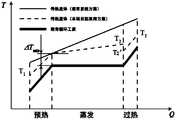
本实施例中,同时采用了塔式集热器12和槽式集热器11;其中,槽式集热器11用于收集温度较低的热量,将流经其加热管的传热流体由温度T1加热到温度T2,该传热流体用于与流经预热器21的朗肯循环工质进行换热;塔式集热器12用于收集温度较高的热量,将流经其加热管的传热流体由温度T2′加热到温度T3,该传热流体用于与流经过热器22的朗肯循环工质换热。In this embodiment, both the
需要说明的是,槽式集热器的传热流体出口温度设计值T2和塔式集热器的传热流体入口温度设计值T2′,两者可以相等,也可以不相等,可根据需求自行设计。在合理调节各换热器中传热流体的质量流量时,若T2 和T2′相等则可得到如图6所示的传热曲线,若T2和T2′不相等则可得到如图7所示的传热曲线,实际上,这两种情况相比,在T2和T2′不相等的情况下,换热温差更小,换热
因此,本实施例不仅可以使塔式集热器12和槽式集热器11能够在各自的最佳工作温度区间内工作,有利于提高系统效率,槽式集热器11的加入还可以提高塔式镜场的场地利用率,降低系统成本。而且,实现了对换热部分的预热段、蒸发段和过热段的分段加热;基于该分段加热方式,各换热器(预热器21、过热器22、再热器23)中的传热流体的质量流量(如图5中的q1、q2、q3所示)可以依据需要进行调整。Therefore, this embodiment can not only enable the
进一步地,通过合理调节各换热器中传热流体的质量流量,如图6和图7所示的本发明实施例与现有传统方案的传热对比示意图,均可以降低各换热器的换热温差,减小换热过程的

实际应用中,可以根据实际需求来预先设置每个换热器的传热流体入口和传热流体出口处的传热流体温度,据此来调节各换热器的传热流体的流量质量(若要增大当前换热器中传热流体曲线的斜率,则减小相应部分的传热流体的质量流量,反之则增加),以达到降低各换热器的换热温差及换热过程中
需要说明的是,朗肯循环工质可以为水,也可选择其它介质,如CO2、有机工质等;传热流体可以为合成油、熔融盐或空气等,具体不限。It should be noted that the Rankine cycle working fluid can be water, or other media, such as CO2, organic working fluid, etc.; the heat transfer fluid can be synthetic oil, molten salt or air, etc., and the specifics are not limited.
此外,本实施例的发电系统还可包括储热装置30,该储热装置30包括:低温储热罐31、中温储热罐32和高温储热罐33。In addition, the power generation system of this embodiment may further include a
其中,低温储热罐31包括一个入口和一个出口,其入口通过第一阀门与第二管道相连,其出口通过第二阀门与第二管道相连,用于储存低温的传热流体。Among them, the low-temperature
高温储热罐33包括一个入口和一个出口,其入口通过第三阀门与第三管道相连,其出口通过第四阀门与第三管道相连,用于储存高温的传热流体。The high-temperature
中温储热罐32包括两个入口和两个出口,其第一入口通过第五阀门与 第一管道相连,其第一出口通过第六阀门与第一管道相连;其第二入口通过第五阀门与第四管道相连,其第二出口通过第六阀门与第四管道相连,用于储存中温的传热流体。The medium temperature
上述低温储热罐31、中温储热罐32和高温储热罐33的应用,实现了三级储热,可以实现自动匹配塔式集热器12和槽式集热器11中传热流体的质量流量,还有助于灵活调整流经各换热器中传热流体的质量流量。The application of the above-mentioned low temperature
此外,本实施例可以利用中温储热罐32来缓冲传热流体,并调节传热流体的流量,稳定换热器中的换热温度和流量,有利于系统稳定发电;利用槽式集热器11收集中温的传热流体,为系统的启动及保温防凝工作提供成本较低的技术。In addition, this embodiment can use the medium-temperature
如图5所示,本实施例的发电系统还包括汽轮机40,该汽轮机40包括高压缸41和中低压缸42。As shown in FIG. 5, the power generation system of this embodiment further includes a
其中,过热器22的工质出口与高压缸41的工质入口相连;高压缸41的工质出口与再热器23的工质入口相连;再热器23的工质出口与中低压缸42的工质入口相连;中低压缸42的第一工质出口与除氧器44的入口相连,中低压缸42的第二工质出口经过凝汽器43与除氧器44的入口相连;除氧器44的出口与预热器21的工质入口相连,预热器21的工质出口与过热器22的工质入口相连。Among them, the working medium outlet of the
需要说明的是,高压缸和中低压缸都可能有抽汽,用于加热给水和除氧器,但为了简单描述本发明实施例的方案,图5提供的示意图中未画出用于加热给水的抽汽口。实际上,高压缸和中低压缸都可能还有更多其他抽汽出口,本发明不作限制。It should be noted that both the high-pressure cylinder and the medium and low-pressure cylinders may have steam extraction for heating the feedwater and deaerator. However, in order to briefly describe the solution of the embodiment of the present invention, the schematic diagram provided in FIG. The steam extraction port. In fact, both the high pressure cylinder and the medium and low pressure cylinder may have more other extraction steam outlets, which are not limited by the present invention.
朗肯循环工质的循环过程为:经过预热且呈蒸汽的朗肯循环工质,进入过热器22加热成过热蒸汽,过热蒸汽在汽轮机40的高压缸41中做功后,形成低压低温的蒸汽进入再热器23,再热器23将该部分蒸汽重新加热成高温蒸汽,高温蒸汽再进入汽轮机40的中低压缸42继续做功,一部分直接进入除氧器44,一部分进入凝汽器43凝结成液态后进入除氧器44;除氧器44进行除氧后,进入预热器21进行预热及汽化蒸发后进入过热器22,从而形成朗肯循环工质的循环回路。The working fluid of the Rankine cycle is as follows: the preheated and steam-like Rankine cycle working fluid enters the
需要说明的是,朗肯循环工质的循环侧结构(包括换热装置20和汽轮机40两部分的内部连接结构),不局限于图5所示的结构,可以根据实际情况灵活调节,具体不限制。It should be noted that the circulation side structure of the Rankine cycle working fluid (including the internal connection structure of the
综上,本发明实施例应用了两种不同类型的集热器和三级储热,可实现对储热量、传热流体流量、系统运行方式等进行即时控制的优化策略,提高了系统的稳定性和灵活性。In summary, the embodiment of the present invention applies two different types of heat collectors and three-stage heat storage, which can realize the optimization strategy of real-time control of heat storage, heat transfer fluid flow, system operation mode, etc., and improve the stability of the system. Sex and flexibility.
实施例二Example two
请参阅图8,本发明实施例提供了另一种太阳能塔槽联合发电系统,包括:集热装置10、储热装置30和换热装置20。Referring to FIG. 8, an embodiment of the present invention provides another solar tower and trough combined power generation system, which includes a
集热装置10,包括:槽式集热器11和塔式集热器12。The
储热装置30,包括:低温储热罐31、中温储热罐32和高温储热罐33。其中,低温储热罐31和高温储热罐33均包括一个入口和一个出口,中温储热罐32包括两个入口和两个出口。The
换热装置20,包括:预热器21、过热器22和再热器23,且预热器21或者过热器22还联合有蒸发器功能。The
槽式集热器11的加热管出口,通过第一管道与中温储热罐32的第一入口相连;中温储热罐32的第一出口,通过第二管道与预热器21的传热流体入口相连;预热器21的传热流体出口,通过第三管道与低温储热罐31的入口相连;低温储热罐31的出口,通过第四管道与槽式集热器11的加热管入口相连。The outlet of the heating pipe of the
塔式集热器12的加热管出口,通过第五管道与高温储热罐33的入口相连;高温储热罐33的出口,通过第六管道与过热器22的传热流体入口和再热器23的传热流体入口分别相连;过热器22的传热流体出口和再热器23的传热流体出口,分别通过第七管道与中温储热罐32的第二入口相连;中温储热罐32的第二出口,通过第八管道与塔式集热器12的加热管入口相连。The outlet of the heating pipe of the
与实施例一的不同之处在于,本实施例二中各储热罐完全作为集热装置10和换热装置20之间的缓冲装置。但是,本实施例二同样实现了两个传热流体循环回路,实现对朗肯循环工质的分段加热,实现原理与实施例 一相同,此处不再赘述。The difference from the first embodiment is that each heat storage tank in the second embodiment is completely used as a buffer device between the
以上所述,以上实施例仅用以说明本发明的技术方案,而非对其限制;尽管参照前述实施例对本发明进行了详细的说明,本领域的普通技术人员应当理解:其依然可以对前述各实施例所记载的技术方案进行修改,或者对其中部分技术特征进行等同替换;而这些修改或者替换,并不使相应技术方案的本质脱离本发明各实施例技术方案的精神和范围。As mentioned above, the above embodiments are only used to illustrate the technical solutions of the present invention, but not to limit them. Although the present invention has been described in detail with reference to the foregoing embodiments, those of ordinary skill in the art should understand that: The technical solutions recorded in the embodiments are modified, or some of the technical features are equivalently replaced; these modifications or replacements do not cause the essence of the corresponding technical solutions to deviate from the spirit and scope of the technical solutions of the embodiments of the present invention.
Claims (9)
Translated fromChinesePriority Applications (1)
| Application Number | Priority Date | Filing Date | Title |
|---|---|---|---|
| ZA2021/10907AZA202110907B (en) | 2020-03-05 | 2021-12-23 | Solar tower and trough combined power generation |
Applications Claiming Priority (2)
| Application Number | Priority Date | Filing Date | Title |
|---|---|---|---|
| CN202010146473.8ACN111173697B (en) | 2020-03-05 | 2020-03-05 | Solar tower trough combined power generation system |
| CN202010146473.8 | 2020-03-05 |
Publications (1)
| Publication Number | Publication Date |
|---|---|
| WO2021174862A1true WO2021174862A1 (en) | 2021-09-10 |
Family
ID=70647231
Family Applications (1)
| Application Number | Title | Priority Date | Filing Date |
|---|---|---|---|
| PCT/CN2020/121428CeasedWO2021174862A1 (en) | 2020-03-05 | 2020-10-16 | Solar tower and trough combined power generation system |
Country Status (3)
| Country | Link |
|---|---|
| CN (1) | CN111173697B (en) |
| WO (1) | WO2021174862A1 (en) |
| ZA (1) | ZA202110907B (en) |
Cited By (5)
| Publication number | Priority date | Publication date | Assignee | Title |
|---|---|---|---|---|
| CN115274170A (en)* | 2022-08-01 | 2022-11-01 | 哈尔滨工程大学 | A high thermal efficiency Brayton and Rankine combined cycle power generation nuclear reactor system |
| CN115875097A (en)* | 2022-11-17 | 2023-03-31 | 华中科技大学 | New energy consumption system based on coupling of cascade type high-temperature heat storage and coal electric unit |
| CN116025547A (en)* | 2022-12-30 | 2023-04-28 | 国网浙江省电力有限公司双创中心 | A tower-slot combined photothermal composite compressed air energy storage system |
| CN116026057A (en)* | 2022-12-19 | 2023-04-28 | 中国石油大学(华东) | Thermochemical combined heat and power generation system based on composite solar reactor |
| CN118936185A (en)* | 2024-10-10 | 2024-11-12 | 上海交通大学 | A power generation system and method for coupling waste plastic gasification with organic Rankine cycle |
Families Citing this family (1)
| Publication number | Priority date | Publication date | Assignee | Title |
|---|---|---|---|---|
| CN111173697B (en)* | 2020-03-05 | 2024-03-08 | 广东海洋大学 | Solar tower trough combined power generation system |
Citations (7)
| Publication number | Priority date | Publication date | Assignee | Title |
|---|---|---|---|---|
| US7296410B2 (en)* | 2003-12-10 | 2007-11-20 | United Technologies Corporation | Solar power system and method for power generation |
| CN102884317A (en)* | 2010-05-06 | 2013-01-16 | 西门子公司 | Solar power plant part of a solar thermal power plant and solar thermal power plant provided with solar collector surfaces for a heat transfer medium and working medium |
| CN202673591U (en)* | 2012-07-25 | 2013-01-16 | 中国电力工程顾问集团华北电力设计院工程有限公司 | Trough and tower solar hybrid power generation system |
| WO2014193224A2 (en)* | 2013-05-27 | 2014-12-04 | Stamicarbon B.V. Acting Under The Name Of Mt Innovation Center | Solar thermal energy storage system |
| CN209586603U (en)* | 2019-01-14 | 2019-11-05 | 中国电力工程顾问集团中南电力设计院有限公司 | Three-tank type fused salt heat storage tower trough coupling photo-thermal power generation system |
| CN111173697A (en)* | 2020-03-05 | 2020-05-19 | 广东海洋大学 | A solar tower-trough combined power generation system |
| CN211950757U (en)* | 2020-03-05 | 2020-11-17 | 广东海洋大学 | A solar tower-trough combined power generation system |
Family Cites Families (4)
| Publication number | Priority date | Publication date | Assignee | Title |
|---|---|---|---|---|
| US20050126171A1 (en)* | 2002-11-01 | 2005-06-16 | George Lasker | Uncoupled, thermal-compressor, gas-turbine engine |
| CN101825072A (en)* | 2010-04-16 | 2010-09-08 | 华中科技大学 | Trough-dish combined solar thermal power generation system with fixed focus |
| CN107542631B (en)* | 2017-09-04 | 2019-05-17 | 中国华能集团清洁能源技术研究院有限公司 | A kind of 3 tank heat storage type points-line focus mixing heat collecting field solar heat power generation system |
| CN209877401U (en)* | 2019-05-07 | 2019-12-31 | 内蒙古电力勘测设计院有限责任公司 | Groove tower coupling solar energy photo-thermal power station stores up heat transfer system |
- 2020
- 2020-03-05CNCN202010146473.8Apatent/CN111173697B/enactiveActive
- 2020-10-16WOPCT/CN2020/121428patent/WO2021174862A1/ennot_activeCeased
- 2021
- 2021-12-23ZAZA2021/10907Apatent/ZA202110907B/enunknown
Patent Citations (7)
| Publication number | Priority date | Publication date | Assignee | Title |
|---|---|---|---|---|
| US7296410B2 (en)* | 2003-12-10 | 2007-11-20 | United Technologies Corporation | Solar power system and method for power generation |
| CN102884317A (en)* | 2010-05-06 | 2013-01-16 | 西门子公司 | Solar power plant part of a solar thermal power plant and solar thermal power plant provided with solar collector surfaces for a heat transfer medium and working medium |
| CN202673591U (en)* | 2012-07-25 | 2013-01-16 | 中国电力工程顾问集团华北电力设计院工程有限公司 | Trough and tower solar hybrid power generation system |
| WO2014193224A2 (en)* | 2013-05-27 | 2014-12-04 | Stamicarbon B.V. Acting Under The Name Of Mt Innovation Center | Solar thermal energy storage system |
| CN209586603U (en)* | 2019-01-14 | 2019-11-05 | 中国电力工程顾问集团中南电力设计院有限公司 | Three-tank type fused salt heat storage tower trough coupling photo-thermal power generation system |
| CN111173697A (en)* | 2020-03-05 | 2020-05-19 | 广东海洋大学 | A solar tower-trough combined power generation system |
| CN211950757U (en)* | 2020-03-05 | 2020-11-17 | 广东海洋大学 | A solar tower-trough combined power generation system |
Cited By (7)
| Publication number | Priority date | Publication date | Assignee | Title |
|---|---|---|---|---|
| CN115274170A (en)* | 2022-08-01 | 2022-11-01 | 哈尔滨工程大学 | A high thermal efficiency Brayton and Rankine combined cycle power generation nuclear reactor system |
| CN115274170B (en)* | 2022-08-01 | 2023-05-23 | 哈尔滨工程大学 | Nuclear reactor system for high-thermal-efficiency Brayton and Rankine combined cycle power generation |
| CN115875097A (en)* | 2022-11-17 | 2023-03-31 | 华中科技大学 | New energy consumption system based on coupling of cascade type high-temperature heat storage and coal electric unit |
| CN116026057A (en)* | 2022-12-19 | 2023-04-28 | 中国石油大学(华东) | Thermochemical combined heat and power generation system based on composite solar reactor |
| CN116026057B (en)* | 2022-12-19 | 2023-08-08 | 中国石油大学(华东) | Thermochemical combined heat and power generation system based on composite solar reactor |
| CN116025547A (en)* | 2022-12-30 | 2023-04-28 | 国网浙江省电力有限公司双创中心 | A tower-slot combined photothermal composite compressed air energy storage system |
| CN118936185A (en)* | 2024-10-10 | 2024-11-12 | 上海交通大学 | A power generation system and method for coupling waste plastic gasification with organic Rankine cycle |
Also Published As
| Publication number | Publication date |
|---|---|
| CN111173697B (en) | 2024-03-08 |
| ZA202110907B (en) | 2022-03-30 |
| CN111173697A (en) | 2020-05-19 |
Similar Documents
| Publication | Publication Date | Title |
|---|---|---|
| CN103953402B (en) | The optimization integrated system of a kind of solar energy and biomass energy cogeneration | |
| US11560879B2 (en) | Solar-aided coal-fired flexible power generation system and operation method thereof | |
| WO2021174862A1 (en) | Solar tower and trough combined power generation system | |
| CN101539123B (en) | Two-stage heat storage solar thermal power generation system combined with trough and tower | |
| CN109296511B (en) | Supercritical carbon dioxide Brayton cycle tower type solar thermal power generation system | |
| CN101413719B (en) | Tower type solar heat power generation system with double-stage thermal storage | |
| CN207064167U (en) | A kind of line-focusing solar couples heat generating system | |
| CN108561282B (en) | Trough type direct steam and molten salt combined thermal power generation system | |
| CN107542631A (en) | A kind of three tank heat storage type point line focus mixing heat collecting field solar heat power generation system | |
| CN209586603U (en) | Three-tank type fused salt heat storage tower trough coupling photo-thermal power generation system | |
| CN209145783U (en) | A supercritical carbon dioxide Brayton cascade cycle solar thermal power generation system | |
| CN105863977A (en) | Supercritical carbon dioxide Brayton cycle power generation system and method | |
| CN105201579A (en) | Supercritical carbon dioxide power generation system based on secondary reflection condensation heat-absorption technique | |
| CN108590989A (en) | The complementary system that tower type solar thermal-arrest is integrated with Gas-steam Combined Cycle | |
| CN101761366B (en) | Light-focusing solar extraction condensing type cogeneration system | |
| CN207568778U (en) | A kind of cooling heating and power generation system based on regenerative resource | |
| CN205690714U (en) | Solar light-heat power-generation heat storage and exchange system | |
| CN102661259B (en) | Integrated solar thermal power generation system | |
| CN107084103A (en) | It is a kind of using carbon dioxide as heat accumulation and do work working medium tower type solar solar-thermal generating system | |
| CN107401488A (en) | All-weather solar electricity-generating method and system based on whole operation with pressure | |
| CN204648712U (en) | A kind of solar parabolic through power generation system | |
| CN107191342A (en) | All-weather solar electricity-generating method and system based on heat engine expansion work | |
| CN107587984A (en) | A kind of cooling heating and power generation system based on regenerative resource | |
| CN110080959A (en) | A kind of hierarchical solar assistant coal electricity generation system | |
| CN209145784U (en) | A supercritical carbon dioxide Brayton cycle tower solar thermal power generation system |
Legal Events
| Date | Code | Title | Description |
|---|---|---|---|
| 121 | Ep: the epo has been informed by wipo that ep was designated in this application | Ref document number:20923293 Country of ref document:EP Kind code of ref document:A1 | |
| NENP | Non-entry into the national phase | Ref country code:DE | |
| 122 | Ep: pct application non-entry in european phase | Ref document number:20923293 Country of ref document:EP Kind code of ref document:A1 |