WO2021172792A1 - Fluid control device using centrifugal force - Google Patents
Fluid control device using centrifugal forceDownload PDFInfo
- Publication number
- WO2021172792A1 WO2021172792A1PCT/KR2021/001669KR2021001669WWO2021172792A1WO 2021172792 A1WO2021172792 A1WO 2021172792A1KR 2021001669 WKR2021001669 WKR 2021001669WWO 2021172792 A1WO2021172792 A1WO 2021172792A1
- Authority
- WO
- WIPO (PCT)
- Prior art keywords
- fluid control
- fixing
- centrifugal force
- control device
- support
- Prior art date
- Legal status (The legal status is an assumption and is not a legal conclusion. Google has not performed a legal analysis and makes no representation as to the accuracy of the status listed.)
- Ceased
Links
Images


Classifications
- B—PERFORMING OPERATIONS; TRANSPORTING
- B04—CENTRIFUGAL APPARATUS OR MACHINES FOR CARRYING-OUT PHYSICAL OR CHEMICAL PROCESSES
- B04B—CENTRIFUGES
- B04B5/00—Other centrifuges
- B04B5/04—Radial chamber apparatus for separating predominantly liquid mixtures, e.g. butyrometers
- B—PERFORMING OPERATIONS; TRANSPORTING
- B01—PHYSICAL OR CHEMICAL PROCESSES OR APPARATUS IN GENERAL
- B01L—CHEMICAL OR PHYSICAL LABORATORY APPARATUS FOR GENERAL USE
- B01L3/00—Containers or dishes for laboratory use, e.g. laboratory glassware; Droppers
- B01L3/50—Containers for the purpose of retaining a material to be analysed, e.g. test tubes
- B01L3/502—Containers for the purpose of retaining a material to be analysed, e.g. test tubes with fluid transport, e.g. in multi-compartment structures
- B01L3/5027—Containers for the purpose of retaining a material to be analysed, e.g. test tubes with fluid transport, e.g. in multi-compartment structures by integrated microfluidic structures, i.e. dimensions of channels and chambers are such that surface tension forces are important, e.g. lab-on-a-chip
- B01L3/50273—Containers for the purpose of retaining a material to be analysed, e.g. test tubes with fluid transport, e.g. in multi-compartment structures by integrated microfluidic structures, i.e. dimensions of channels and chambers are such that surface tension forces are important, e.g. lab-on-a-chip characterised by the means or forces applied to move the fluids
- B—PERFORMING OPERATIONS; TRANSPORTING
- B01—PHYSICAL OR CHEMICAL PROCESSES OR APPARATUS IN GENERAL
- B01L—CHEMICAL OR PHYSICAL LABORATORY APPARATUS FOR GENERAL USE
- B01L3/00—Containers or dishes for laboratory use, e.g. laboratory glassware; Droppers
- B01L3/50—Containers for the purpose of retaining a material to be analysed, e.g. test tubes
- B01L3/502—Containers for the purpose of retaining a material to be analysed, e.g. test tubes with fluid transport, e.g. in multi-compartment structures
- B01L3/5027—Containers for the purpose of retaining a material to be analysed, e.g. test tubes with fluid transport, e.g. in multi-compartment structures by integrated microfluidic structures, i.e. dimensions of channels and chambers are such that surface tension forces are important, e.g. lab-on-a-chip
- B01L3/502738—Containers for the purpose of retaining a material to be analysed, e.g. test tubes with fluid transport, e.g. in multi-compartment structures by integrated microfluidic structures, i.e. dimensions of channels and chambers are such that surface tension forces are important, e.g. lab-on-a-chip characterised by integrated valves
- B—PERFORMING OPERATIONS; TRANSPORTING
- B01—PHYSICAL OR CHEMICAL PROCESSES OR APPARATUS IN GENERAL
- B01L—CHEMICAL OR PHYSICAL LABORATORY APPARATUS FOR GENERAL USE
- B01L3/00—Containers or dishes for laboratory use, e.g. laboratory glassware; Droppers
- B01L3/50—Containers for the purpose of retaining a material to be analysed, e.g. test tubes
- B01L3/502—Containers for the purpose of retaining a material to be analysed, e.g. test tubes with fluid transport, e.g. in multi-compartment structures
- B01L3/5027—Containers for the purpose of retaining a material to be analysed, e.g. test tubes with fluid transport, e.g. in multi-compartment structures by integrated microfluidic structures, i.e. dimensions of channels and chambers are such that surface tension forces are important, e.g. lab-on-a-chip
- B01L3/502746—Containers for the purpose of retaining a material to be analysed, e.g. test tubes with fluid transport, e.g. in multi-compartment structures by integrated microfluidic structures, i.e. dimensions of channels and chambers are such that surface tension forces are important, e.g. lab-on-a-chip characterised by the means for controlling flow resistance, e.g. flow controllers, baffles
- B—PERFORMING OPERATIONS; TRANSPORTING
- B01—PHYSICAL OR CHEMICAL PROCESSES OR APPARATUS IN GENERAL
- B01L—CHEMICAL OR PHYSICAL LABORATORY APPARATUS FOR GENERAL USE
- B01L3/00—Containers or dishes for laboratory use, e.g. laboratory glassware; Droppers
- B01L3/50—Containers for the purpose of retaining a material to be analysed, e.g. test tubes
- B01L3/502—Containers for the purpose of retaining a material to be analysed, e.g. test tubes with fluid transport, e.g. in multi-compartment structures
- B01L3/5027—Containers for the purpose of retaining a material to be analysed, e.g. test tubes with fluid transport, e.g. in multi-compartment structures by integrated microfluidic structures, i.e. dimensions of channels and chambers are such that surface tension forces are important, e.g. lab-on-a-chip
- B01L3/502753—Containers for the purpose of retaining a material to be analysed, e.g. test tubes with fluid transport, e.g. in multi-compartment structures by integrated microfluidic structures, i.e. dimensions of channels and chambers are such that surface tension forces are important, e.g. lab-on-a-chip characterised by bulk separation arrangements on lab-on-a-chip devices, e.g. for filtration or centrifugation
- B—PERFORMING OPERATIONS; TRANSPORTING
- B04—CENTRIFUGAL APPARATUS OR MACHINES FOR CARRYING-OUT PHYSICAL OR CHEMICAL PROCESSES
- B04B—CENTRIFUGES
- B04B5/00—Other centrifuges
- B04B5/04—Radial chamber apparatus for separating predominantly liquid mixtures, e.g. butyrometers
- B04B5/0442—Radial chamber apparatus for separating predominantly liquid mixtures, e.g. butyrometers with means for adding or withdrawing liquid substances during the centrifugation, e.g. continuous centrifugation
- B—PERFORMING OPERATIONS; TRANSPORTING
- B04—CENTRIFUGAL APPARATUS OR MACHINES FOR CARRYING-OUT PHYSICAL OR CHEMICAL PROCESSES
- B04B—CENTRIFUGES
- B04B7/00—Elements of centrifuges
- B04B7/08—Rotary bowls
- G—PHYSICS
- G01—MEASURING; TESTING
- G01N—INVESTIGATING OR ANALYSING MATERIALS BY DETERMINING THEIR CHEMICAL OR PHYSICAL PROPERTIES
- G01N1/00—Sampling; Preparing specimens for investigation
- G01N1/28—Preparing specimens for investigation including physical details of (bio-)chemical methods covered elsewhere, e.g. G01N33/50, C12Q
- G01N1/40—Concentrating samples
- B—PERFORMING OPERATIONS; TRANSPORTING
- B01—PHYSICAL OR CHEMICAL PROCESSES OR APPARATUS IN GENERAL
- B01L—CHEMICAL OR PHYSICAL LABORATORY APPARATUS FOR GENERAL USE
- B01L2200/00—Solutions for specific problems relating to chemical or physical laboratory apparatus
- B01L2200/02—Adapting objects or devices to another
- B01L2200/028—Modular arrangements
- B—PERFORMING OPERATIONS; TRANSPORTING
- B01—PHYSICAL OR CHEMICAL PROCESSES OR APPARATUS IN GENERAL
- B01L—CHEMICAL OR PHYSICAL LABORATORY APPARATUS FOR GENERAL USE
- B01L2200/00—Solutions for specific problems relating to chemical or physical laboratory apparatus
- B01L2200/06—Fluid handling related problems
- B01L2200/0621—Control of the sequence of chambers filled or emptied
- B—PERFORMING OPERATIONS; TRANSPORTING
- B01—PHYSICAL OR CHEMICAL PROCESSES OR APPARATUS IN GENERAL
- B01L—CHEMICAL OR PHYSICAL LABORATORY APPARATUS FOR GENERAL USE
- B01L2300/00—Additional constructional details
- B01L2300/08—Geometry, shape and general structure
- B01L2300/0803—Disc shape
- B—PERFORMING OPERATIONS; TRANSPORTING
- B01—PHYSICAL OR CHEMICAL PROCESSES OR APPARATUS IN GENERAL
- B01L—CHEMICAL OR PHYSICAL LABORATORY APPARATUS FOR GENERAL USE
- B01L2400/00—Moving or stopping fluids
- B01L2400/04—Moving fluids with specific forces or mechanical means
- B01L2400/0403—Moving fluids with specific forces or mechanical means specific forces
- B01L2400/0409—Moving fluids with specific forces or mechanical means specific forces centrifugal forces
Definitions
- This embodimentrelates to a fluid control device using centrifugal force, and more particularly, to a fluid control device using centrifugal force for automating a chemical reaction or physical unit operation through movement, separation, and mixing of a fluid.
- a lab-on-a-discthat is, a fluid control device using centrifugal force
- a fluid control device using centrifugal forceis a device capable of performing various functions by appropriately using a technology for controlling the flow of a fluid using centrifugal force and a valve.
- a fluid control device using centrifugal forcecan be used for diagnosis or quarantine by rapidly analyzing a fluid in a biomedical field or a livestock field.
- Such a fluid control devicemay generally be formed as a single circular disk.
- whole blood or various biological liquidsmay be separated from its components or parts.
- whole bloodis composed of plasma, various white blood cells, platelets, and red blood cells, and may be separated for each component by using a centrifugal separator.
- centrifugal separatorFor example, in order to separate whole blood for each component using a centrifugal separator, whole blood was put into a single tube container and then put into a centrifugal separator to separate based on specific gravity. The centrifuged fluid is stacked in several layers for each component based on specific gravity, and each component stacked in layers in this way is manually recovered.
- a fluid control device using centrifugal forcemay be applied to easily extract a desired component without recontamination in the extraction process after separating the fluid for each component.
- the centrifugal force-based fluid control devicethat is currently commercialized and used in various applications uses a very small flow rate of about 1 ml, so the disk is thin and the manufacturing difficulty is not high.
- the thickness and size of the disk rotating in the fluid control deviceis increased, and the input channel is large and long for fast fluid movement. Accordingly, the fluid control device using the centrifugal force increases in weight and size, making it difficult to maintain a designed shape during injection molding, manufacturing difficulty is high, and productivity is low.
- an object of the present inventionis to provide a fluid control device using centrifugal force that is easily fixed to a fluid control unit including a plurality of chambers to prevent vibration during rotation and is well fixed to a rotating shaft so that position control can be precisely performed.
- a fluid control apparatus using centrifugal forceincludes a fluid control unit including a plurality of chambers and controlling the movement of a fluid in the chamber; a lower fixing part located under the fluid control part and fixing the plurality of chambers; an upper fixing part located above the fluid control part and fixing the plurality of chambers; and a fastening member for fastening through the lower fixing part, the fluid control part, and the upper fixing part, wherein each of the plurality of chambers is disposed to face each other and placed on the lower fixing part.
- the chambermay have a sectoral shape in plan view, and adjacent chambers may have a spacer and be spaced apart from each other.
- the lower fixing partincludes a support part for supporting the fluid control part, and a lower edge part installed along the edge of the support part to form a seating groove for seating the fluid control part, and the inner wall of the lower edge part has a plurality of lower fixing grooves.
- the outer sidewall of the chambermay have a sidewall fixing protrusion coupled to the lower fixing groove.
- the side wall fixing protrusionmay be linear.
- the fastening membermay include a lower fastening part positioned at the center of the support part, and an upper fastening part positioned at the center of the upper fixing part and fastened to the lower fastening part.
- the lower coupling partmay include a circular central support part and a protrusion installed on the central support part, and an inner sidewall of the fluid control part may be fixed in contact with a sidewall of the central support part.
- An upper surface of the supportmay have a plurality of support fixing grooves
- a lower surface of the chambermay have a plurality of lower circular protrusions
- the support fixing groovesmay be coupled to the lower circular protrusions.
- the plurality of support fixing groovesmay be formed at positions corresponding to corners of the sector-shaped chamber.
- the lower fixing partmay further include a plurality of linear fixing parts positioned on the support part, and the linear fixing part may connect the lower edge part and the central support part.
- the linear fixing partmay be coupled to the spacer.
- the upper fixing partincludes an upper edge part overlapping the lower edge part, a central part spaced apart from the upper edge part and corresponding to the lower fastening part, and a plurality of branch parts connecting the upper edge part and the central part, , the branch portion may be coupled to the separation portion.
- a fluid control device using centrifugal forcefixes a fluid control unit separated into a plurality of chambers symmetrically to a rotation axis using a lower fixing part, an upper fixing part, and a fastening member, thereby generating by individual centrifugal force during rotation It is possible to prevent vibration of the fluid control unit that may be caused and precisely control the position.
- the branch portion of the upper fixing unitis inserted into and coupled to a space (ex. a spaced part) between the separated individual chambers of the fluid control unit, thereby fixing the position of each chamber.
- FIG. 1is an exploded perspective view of a fluid control device using centrifugal force according to an exemplary embodiment
- FIG. 2is a plan view of the lower fixing part of FIG. 1 .
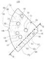
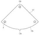
- FIG. 3is a plan view of each chamber of the fluid control unit of FIG. 1 ;
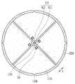
- FIG. 4is a plan view illustrating a state in which a fluid control unit of a fluid control device using centrifugal force is fixed to a lower fixing unit according to an exemplary embodiment.
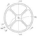
- FIG. 5is a plan view of the upper fixing part of FIG. 1 ;
- FIG. 6is a cross-sectional view taken along the line VI-VI' of FIG. 5 .
- FIG. 7is a cross-sectional view taken along line VII-VII' of FIG. 5 .
- FIG. 8is a plan view illustrating a state in which the fluid control unit of the fluid control device using centrifugal force is fixed by a lower fixing unit and an upper fixing unit according to an exemplary embodiment.
- FIG. 9is a plan view schematically illustrating a fluid control unit of a fluid control device using centrifugal force according to an exemplary embodiment.
- FIG. 10is an exploded perspective view of the fluid control unit of FIG. 9 .
- FIG. 11is a cross-sectional view illustrating the chamber of FIG. 9 taken along line XI-XI'.
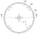
- FIG. 12is a plan view of a lower fixing part of a fluid control device using centrifugal force according to another exemplary embodiment.
- FIG. 13is a schematic cross-sectional perspective view taken along the line XIII-XIII' of FIG. 12 .
- FIG. 14is a bottom view of a chamber of a fluid control unit of a fluid control device using centrifugal force according to another exemplary embodiment.
- 15is a plan view of a lower fixing part of a fluid control device using centrifugal force according to another exemplary embodiment.
- 16is a schematic cross-sectional perspective view taken along the line XVI-XVI' of FIG. 15 .
- a part of a layer, film, region, plate, etc.when a part of a layer, film, region, plate, etc. is said to be “on” or “on” another part, it includes not only cases where it is “directly on” another part, but also cases where another part is in between. . Conversely, when we say that a part is “just above” another part, we mean that there is no other part in the middle.
- the reference portionis located above or below the reference portion, and does not necessarily mean to be located “on” or “on” the opposite direction of gravity. .
- planarit means when the target part is viewed from above, and "in cross-section” means when viewed from the side when a cross-section of the target part is vertically cut.
- FIG. 1is an exploded perspective view of a fluid control device using centrifugal force according to an embodiment
- FIG. 2is a plan view of the lower fixing part of FIG. 1
- FIG. 3is a plan view of each chamber of the fluid control unit of FIG. 1
- FIG. Itis a plan view showing a state in which the fluid control unit of the fluid control device using centrifugal force is fixed with a lower fixing unit according to an embodiment
- FIG. 5is a plan view of the upper fixing unit of FIG. 1
- FIG. 6is VI-VI' of FIG. It is a cross-sectional view cut along the line
- FIG. 7is a cross-sectional view cut along the line VII-VII' of FIG. 5
- FIG. 8is a lower fixing part and It is a plan view showing the state fixed by the upper fixing part.
- the fluid control apparatus using centrifugal forceincludes a fluid control unit 1000 , a lower fixing unit 2000 , an upper fixing unit 3000 , and a fastening member 4000 .
- the fluid control unit 1000includes a plurality of chambers 1100 , and the chamber 1100 may have a planar sectoral shape. Accordingly, the fluid control unit 1000 including the plurality of chambers 1100 may have a planar circular shape as a whole. In this case, the plurality of chambers 1100 are sequentially arranged adjacent to each other, and the adjacent chambers 1100 may have a spaced portion 1 (refer to FIG. 4 ) of a predetermined distance d and may be spaced apart from each other.
- the fluid control unit 1000When the fluid control unit is manufactured as a single structure by injection or the like, it is difficult to completely implement the complex internal structure of the fluid control unit. Accordingly, in the present embodiment, by dividing the fluid control unit 1000 into a plurality of chambers 1100 and manufacturing (eg, 4 divisions), it is possible to maintain the quality of injection.
- the outer sidewall 110a of the chamber 1100may have a planar arc shape
- the inner sidewall 110c of the chambermay also have a planar arc shape
- the outer sidewall 110a of the chambermay have at least one sidewall fixing protrusion 110b.
- the sidewall fixing protrusion 110bmay have a linear shape extending in a vertical direction.
- the fluid control unitis composed of four chambers, but is not limited thereto, and may be composed of various number of chambers.
- the lower fixing unit 2000is located under the fluid control unit 1000 and may fix the plurality of chambers 1100 to each other.
- the lower fixing part 2000may include a support part 2100 , a lower edge part 2200 , and a rotation shaft 2300 .
- the support part 2100has a circular shape in plan view and may support a plurality of chambers 1100 .
- the lower edge part 2200may be installed along the edge of the support part 2100 to form a seating groove for seating the fluid control part 110 .
- the inner wall of the lower edge part 2200may have a plurality of lower fixing grooves 220a. Although four lower fixing grooves 220a are illustrated in the present embodiment, the present invention is not limited thereto, and an appropriate number of lower fixing grooves may be formed.
- the sidewall fixing protrusion 110bmay be coupled to the lower fixing groove 220a to fix the fluid control unit 1000 .
- the rotating shaft 2300may be coupled to a separate rotor (not shown) to transmit the rotational force of the rotor to the fluid control unit 1000 .
- the upper fixing unit 3000is located above the fluid control unit 1000 and may fix the plurality of chambers 1100 to each other.
- the upper fixing part 3000may include an upper edge part 310 , a central part 320 , and a plurality of branch parts 330 .
- the upper edge part 310has a circular ring shape and may overlap the lower edge part 2200 of the lower fixing part 2000 .
- the central part 320is spaced apart from the upper edge part 310 and may be positioned to correspond to the fastening member 4000 .
- the central part 320may be located in the inner direction of the upper edge part 310 .
- the central portion 320may have a through hole 320a.
- the plurality of branch portions 310may have a linear shape and may connect the upper edge portion 310 and the central portion 320 .
- the plurality of branch portions 310may be formed at positions corresponding to the spaced portions 1 of the fluid control unit 1000 .
- the branch portion 310may be coupled to the spacer 1 to fix the plurality of chambers 1100 to each other. That is, since the branch portion 310 is coupled to the spacer 1 , the space between the adjacent chambers 1100 is filled, thereby limiting the movement of the chamber 1100 . Accordingly, during the centrifugal separation operation, vibration and bending of the chamber 1100 may be prevented.
- the fastening member 4000may pass through the lower fixing unit 2000 , the fluid control unit 1000 , and the upper fixing unit 3000 in order to fasten them.
- the fastening member 4000may include a lower fastening part 410 and an upper fastening part 420 disposed at positions corresponding to each other.
- the lower fastening part 410may be located in the center of the support part 2100 .
- the lower coupling part 410may include a circular central support part 411 , and a protrusion 412 installed on the central support part 411 and fastened to the upper coupling part.
- the lower fastening part 410may have a bolt shape or the like.
- the upper fastening part 420is located in the center of the upper fixing part 3000 , and may pass through the through hole 320a of the central part 320 to be fastened to the lower fastening part 410 .
- the upper fastening part 410may have a nut shape or the like.
- the fastening member 4000is shown as a structure in which the fastening member 4000 is formed in the shape of a bolt and a nut, but it is not necessarily limited thereto.
- a variety of arbitrary structuresare possible, such as structures and the like.
- the fluid controller 1000does not move in the vertical direction using the lower fastening part 410 positioned at the lower part of the fluid controller 1000 and the upper fastening part 420 positioned at the upper part of the fluid controller 1000 . can be fixed so as not to
- the inner sidewall 110c of the fluid control unit 1000may contact the sidewall of the central supporter 411 to fix the chamber 1100 .
- the outer sidewall 110a of the chamberhas the sidewall fixing protrusion 110b coupled with the lower fixing groove 220a of the lower fixing part 2000 to fix the chamber 1100 , and the inner sidewall of the fluid control unit 1000 .
- the 110cmay be fixed so that the chamber 1100 does not move on a plane.
- each chamber of the fluid control unit of the fluid control device using centrifugal forcewill be described in detail with reference to FIGS. 9 to 11 .
- the chamber of the fluid control unitis a centrifugal separation chamber
- the present inventionis not limited thereto, and the chamber of the fluid control unit is a chamber of various diagnostic devices such as a DNA prep chamber. .
- FIG. 9is a plan view schematically illustrating a fluid control unit of a fluid control device using centrifugal force according to an embodiment
- FIG. 10is an exploded perspective view of the fluid control unit of FIG. 9
- FIG. 11is the chamber of FIG. 9 XI-XI' It is a cross-sectional view cut along a line.
- the chamber 1100includes an upper plate 100 , a body 200 , and a lower plate 300 .
- the body 200includes a separation unit 210 in which the centrifuged fluid is separated for each component and an extraction unit 220 for accommodating the fluid separated by component in the separation unit 210 .
- the separation unit 210includes a first separation unit 211 , a second separation unit 212 , and a third separation unit 213 positioned side by side in one direction. In this case, each region of the first separation unit 211 and the second separation unit 212 is separated by a first partition wall 311 positioned in the separation unit 210 .
- the first partition wall 311may be formed to have a predetermined distance H1 from the upper plate 100 .
- the second partition wall 312may be formed to have a predetermined distance H2 from the upper plate 100 .
- the gap H1 between the first partition wall 311 and the upper plate 100 and the gap H2 between the second partition wall 312 and the upper plate 100are not necessarily the same. . This can be appropriately adjusted according to the characteristics of the component to be separated, for example, whether it is a solid component or a liquid component, and the amount of the component to be separated.
- first partition wall 311 and the second partition wall 312may have, for example, a structure protruding from the lower plate 300 , and protrude from the inner sidewall of the separation part 210 of the main body 200 . It may have a structure in the form in which it is applied, and the form is not particularly limited.
- a buffy coat including a large number of white blood cellsis located in the second separation unit 212 after centrifugation, and red blood cells are located in the third separation unit 213 .
- a component comprising a plurality ofis located.
- the blood components located in the third separator 213are The component corresponding to the buffy coat moves to the region of the second separation unit 212 on the second partition wall 312, and the component containing a large number of red blood cells among the components of the blood located in the second separation unit 212 is the first The second partition wall 312 moves to the third separation unit 213 .
- the separation unit 210includes the first separation unit 211 , the second separation unit 212 , and the third separation unit 213 , each component of the centrifuged fluid is first separated for each component.
- the portion 211 , the second separation unit 212 , and the third separation unit 213may be respectively located.
- the main body 200includes an inlet extension 271 , and the inlet extension 271 is connected to the injection path 341 located at the lower portion of the main body 200 .
- the separation unitincludes the first separation unit to the third separation unit, but if necessary, a separation unit may be further added.
- the first vent hole 131is preferably located in a region close to the rotation shaft 2300 of the centrifugal separator in the upper plate 100 .
- the fluid injected for centrifugationfor example, blood
- the third separator regionlocated farthest from the rotation shaft 2300 of the centrifugal separator.
- the fluid injectionis smooth.
- the fluidcan be quickly and easily injected into the chamber for a centrifugal separation device without damaging the active ingredient contained in the fluid, for example, cells, etc. because bubbles do not form in the fluid.
- the main body 200includes an extraction unit 220 , and the extraction unit 220 includes a first extraction unit 221 , a second extraction unit 222 , and a third extraction unit 223 .
- the first extraction unit 221is a space for moving and accommodating components separated by the first separation unit 211
- the second extraction unit 222is configured to further separate the components moved to the first extraction unit 221 . It is a space for moving and accommodating additional separated components afterward.
- the first separation unit 211is connected to the first extraction path 321 located in the lower portion of the main body (200). The components separated by the first separation unit 211 after centrifugation are moved through the first extraction path 321 connected to the first separation unit 211 and accommodated in the first extraction unit 221 .
- the body 200includes a first valve unit 231 positioned to overlap a partial region of the first extraction path 321 .
- the first valveis positioned in the first valve unit 231 , and the first extraction path 321 is opened and closed by the first valve. Therefore, in order to extract the components separated by the first separation unit 211 after centrifugation, the components separated in the first separation unit are first extracted by driving the first valve to open the first extraction path 321 . It can be moved to the unit 221 .
- the components accommodated in the first extraction unit 221 through the first extraction path 321are further separated by performing centrifugal separation once more, and the first extraction unit ( It may be moved to the second extraction unit 222 through the second extraction path 322 connected to the 221 . In this case, it is possible to more reliably remove contaminants from the components separated by centrifugation in the first separation unit.
- the separated component positioned in the first separation unit 211 through centrifugationis plasma.
- Such plasmais used for genomic analysis of cell free DNA, which is used as a method of liquid biopsy to perform diagnosis using a part of a specific tissue secreted into blood without directly extracting the patient's tissue. That is, in the genomic analysis of free DNA, a method of increasing the accuracy of diagnosis by further centrifuging the plasma obtained after separation of the components of whole blood twice to remove contaminants is common. In this case, it is necessary to manually divide the components of the blood by changing several tubes, and to centrifuge them continuously again, which takes a lot of time and effort. cause the rise.
- the supernatant separated in the first extraction unit 221is transferred to the second extraction unit 222 .
- the second extraction unit 222By accommodating it, it is possible to obtain a plasma that is not contaminated by other DNA components.
- the first extraction part 221includes a second vent hole extension part 252 on the sealed upper surface, and the second vent hole extension part 252 has a second vent hole 132 located in the upper plate 100 . ) and is a unitary structure.
- the second vent hole 132is formed when the component separated by the first separation unit 211 is moved to the first extraction unit 221 , that is, when the first valve is opened, the second vent hole 132 is also should be open
- the component additionally separated by the first extraction unit 221is moved to the second extraction unit 222 , that is, when the second valve is opened, the second vent hole 132 must also be opened.
- the second vent hole 132may also be closed.
- the first extraction unit 221is connected to the second extraction path located at the lower portion of the main body 200 .
- the components further centrifuged as described above in the first extraction unit 221are moved through the second extraction path 322 connected to the first extraction unit 221 and accommodated in the second extraction unit 222 .
- the second extraction unit 222includes a first extraction unit 241 .
- the first draw-out part 241may have a conical structure in which the upper and lower surfaces of the main body 200 are open and the upper part has a larger diameter than the lower part.
- the upper opening of the first draw-out part 241has a structure integral with the first draw-out hole 121 positioned on the upper plate 100 .
- the component further separated and accommodated in the second extraction unit 222may be withdrawn to the outside through the first outlet 121 .
- the withdrawal to the outside through the first outlet 121may be performed using, for example, a pipette.
- the second separation unit 212is connected to the third extraction path 323 located in the lower portion of the main body (200).
- the components separated by the second separator 212 after centrifugationare moved through the third extraction path 323 connected to the second separator 212 and accommodated in the third extraction part 223 .
- the main body 200includes a third valve unit 233 positioned to overlap a partial region of the third extraction path 323 .
- a third valveis positioned in the third valve unit 233 , and the third extraction path 323 is opened and closed by the third valve. Therefore, in order to extract the components separated by the second separation unit 212 after centrifugation, the third valve is driven to open the third extraction path 323 to remove the components separated in the second separation unit 212 . 3 may be moved to the extraction unit 223 .
- the third extractor 223includes a second extractor 242 .
- the second lead-out part 242may have a conical structure in which the upper and lower surfaces of the main body 200 are open and the upper part has a larger diameter than the lower part.
- the upper opening of the second lead-out part 242has a structure integral with the second lead-out hole 122 positioned on the upper plate 100 .
- the component accommodated in the third extractor 223may be withdrawn to the outside through the second outlet 122 .
- the withdrawal to the outside through the second outlet 122may be performed using, for example, a pipette.
- the upper plate 100is for preventing contamination when injecting a fluid for centrifugation or withdrawing each centrifuged component to the outside.
- the inlet 101is for injecting a fluid into the separation unit before centrifugation, and the outlet is for extracting each component of the centrifuged fluid for each component.
- the central part 320 of the upper fixing part 3000may be disposed to overlap the injection hole 101 .
- the outletincludes a first outlet 121 and a second outlet 122 .
- the first outlet 121is for withdrawing the components accommodated in the second extraction unit 222 among the components of the centrifuged fluid to the outside.
- the component accommodated in the second extraction unit 222is, for example, a component having a relatively low density after centrifugation and then moving the component separated in the first separation unit to the first extraction unit 221 . It is a high-purity liquid component that is further separated and moved to the second extraction unit 222 .
- the second outlet 122is for drawing out the components accommodated in the third extraction unit 223 among the components of the centrifuged fluid to the outside.
- the upper plate 100includes a first vent hole 131 and a second vent hole 132 together with an inlet and an outlet.
- the first vent hole 131is located on the upper surface of the first separation unit 211 located in the main body 200 . If necessary, when the upper surface of the separation unit 210 has a closed structure, a first vent hole extension (not shown) may be formed on the upper surface of the first separation unit 211 .
- the second vent hole 132is connected to the second vent hole extension part 252 included in the first extraction part 221 located in the main body 200 .
- the upper plate 100includes a first valve hole 111 , a second valve hole 112 , and a third valve hole 113 .
- the first valve hole 111is connected to the first valve unit 231 .
- the first valve unit 231is positioned to overlap a partial region of the first extraction path 321 positioned in the main body 200 .
- the first valve located in the first valve unit 231is driven through the first valve hole 111, and is separated from the first separation unit by opening and closing the first extraction path 321 through the first valve. You can control the movement of ingredients.
- the second valve hole 112is connected to the second valve unit 232 .
- the second valve unit 232is positioned to overlap a partial region of the second extraction path 322 positioned in the main body 200 .
- the second valve located in the second valve unit 232is driven through the second valve hole, and the component accommodated in the first extraction unit 221 by opening and closing the second extraction path 322 through the second valve can control the movement of
- the third valve hole 113is connected to the third valve unit 233 .
- the third valve unit 233is positioned to overlap a partial region of the third extraction path 323 .
- the third valve located in the third valve unit 233is driven through the third valve hole 113 and opens and closes the third extraction path 323 through the third valve to open and close the second separation unit 212 . It is possible to control the movement of separated components into the
- the lower plate 300seals the opening partially formed in the lower portion of the body 200 .
- first partition wall 311 and the second partition wall 312are formed in the main body 200
- first partition wall 311 and the second partition wall 312may be formed to protrude from the lower plate 300 if necessary.
- the side wall fixing protrusion of the chamberis coupled to the lower fixing groove formed on the inner wall of the lower edge of the lower fixing part to fix the chamber, but the support fixing formed in the supporting part of the lower fixing part is fixed.
- Other embodiments of fixing the chamber using groovesare also possible.
- FIG. 12is a plan view of a lower fixing part of a fluid control device using centrifugal force according to another embodiment
- FIG. 13is a schematic cross-sectional perspective view taken along line XIII-XIII' of FIG. 12
- FIG. 14is another embodiment It is a bottom view of the chamber of the fluid control device of the fluid control device using centrifugal force according to FIG.
- FIGS. 12 to 14is substantially the same as that of the embodiment shown in FIGS. 1 to 8 except for the structure of the lower fixing part and the chamber, and repeated description will be omitted.
- the lower fixing part 2000 of the fluid control device using centrifugal forceincludes a support part 2100, a lower edge part 2200, and a rotation shaft 2300. may include.
- the support part 2100has a circular shape in plan view and may support a plurality of chambers 1100 .
- the upper surface of the support part 2100may have a plurality of support fixing grooves 2 .
- the support fixing groove 2may have a circular shape.
- the plurality of support fixing grooves 2may be formed at positions corresponding to the corners of the sector-shaped chamber 1100 . More specifically, the plurality of support fixing grooves 2 are adjacent to the lower edge portion 2200 , the first support fixing groove 3 , and the plurality of second support grooves formed adjacent to the edges of the central support part 411 . It may include a fixing groove (4).
- the lower surface of the chamber 1100may have a plurality of lower surface circular protrusions P. Accordingly, the support fixing groove 2 is coupled to the circular protrusion P on the lower surface to limit the sliding movement of the chamber 1100 on the support part 2100 to fix the position of the chamber 1100 .
- the chamberwas fixed using a circular support fixing groove formed in the support part of the lower fixing part, but the chamber was fixed using the linear fixing part formed in the support part of the lower fixing part.
- Other embodimentsare also possible.
- FIG. 15is a plan view of a lower fixing part of a fluid control device using centrifugal force according to another embodiment
- FIG. 16is a schematic cross-sectional perspective view taken along line XVI-XVI' of FIG. 15 .
- the lower fixing part 2000 of the fluid control device using centrifugal forceincludes a support part 2100, a lower edge part 2200, a rotation shaft 2300, And it may include a plurality of linear fixing parts (2400).
- the support part 2100has a circular shape in plan view and may support a plurality of chambers 1100 .
- the plurality of linear fixing parts 2400may be positioned to protrude above the support part.
- the linear fixing part 2400may connect the lower edge part 2200 and the central support part 411 .
- the linear fixing part 2400may be formed at a position corresponding to the spaced part 1 of the fluid control unit 1000 . Accordingly, the linear fixing unit 2400 may be coupled to the spacer 1 to limit the sliding movement of the chamber 1100 on the support 2100 to fix the position of the chamber 1100 .
Landscapes
- Chemical & Material Sciences (AREA)
- Health & Medical Sciences (AREA)
- Analytical Chemistry (AREA)
- General Health & Medical Sciences (AREA)
- Dispersion Chemistry (AREA)
- Hematology (AREA)
- Clinical Laboratory Science (AREA)
- Chemical Kinetics & Catalysis (AREA)
- Life Sciences & Earth Sciences (AREA)
- Physics & Mathematics (AREA)
- Biochemistry (AREA)
- General Physics & Mathematics (AREA)
- Immunology (AREA)
- Pathology (AREA)
- Molecular Biology (AREA)
- Centrifugal Separators (AREA)
Abstract
Description
Translated fromKorean본 실시예는 원심력을 이용한 유체 제어 장치에 관한 것으로서, 보다 구체적으로, 유체의 이동과 분리, 혼합 등을 통해 화학 반응이나 물리적인 단위 조작을 자동화하는 원심력을 이용한 유체 제어 장치에 관한 것이다.This embodiment relates to a fluid control device using centrifugal force, and more particularly, to a fluid control device using centrifugal force for automating a chemical reaction or physical unit operation through movement, separation, and mixing of a fluid.
일반적으로 랩온어디스크 (Lab-on-a-Disc), 즉 원심력을 이용한 유체 제어 장치는 원심력을 사용하여 유체의 흐름을 제어하는 기술과 밸브를 적절히 이용함으로써 다양한 기능을 수행할 수 있는 장치이다. 특히, 원심력을 이용한 유체 제어 장치는 바이오 메디컬 분야 또는 축산 분야 등에서 유체를 빠른 속도로 분석하여 진단 또는 검역 등에 사용할 수 있다. 이러한 유체 제어 장치는 일반적으로 하나의 원형 디스크로 형성될 수 있다.In general, a lab-on-a-disc, that is, a fluid control device using centrifugal force, is a device capable of performing various functions by appropriately using a technology for controlling the flow of a fluid using centrifugal force and a valve. In particular, a fluid control device using centrifugal force can be used for diagnosis or quarantine by rapidly analyzing a fluid in a biomedical field or a livestock field. Such a fluid control device may generally be formed as a single circular disk.
한편, 전혈(whole blood) 또는 다양한 생물학적 액체들은 그 구성 요소들 또는 부분들로부터 분리될 수 있다. 예를 들어, 전혈은, 플라즈마(plasma), 다양한 백혈구 세포 (white blood cell), 혈소판 및 적혈구 등으로 구성되는데, 원심 분리 장치를 이용하여 각 성분 별로 분리할 수 있다.On the other hand, whole blood or various biological liquids may be separated from its components or parts. For example, whole blood is composed of plasma, various white blood cells, platelets, and red blood cells, and may be separated for each component by using a centrifugal separator.
예를 들면, 원심 분리 장치를 이용하여 전혈을 각 성분 별로 분리하기 위하여 단일 튜브 용기에 전혈을 투입한 후 이를 원심 분리 장치에 투입하여 비중을 기초로 분리하였다. 이와 같이 원심 분리된 유체는 비중에 기초하여 각 성분 별로 여러 개의 층으로 적층되며, 이와 같이 층을 이루며 적층된 각 성분은 수작업으로 회수하였다.For example, in order to separate whole blood for each component using a centrifugal separator, whole blood was put into a single tube container and then put into a centrifugal separator to separate based on specific gravity. The centrifuged fluid is stacked in several layers for each component based on specific gravity, and each component stacked in layers in this way is manually recovered.
그런데, 일반적으로 수작업으로 성분 별로 적층된 유체의 각 층을 분리할 경우에는, 작업 효율이 현저히 저하되고, 원심 분리된 각 성분들이 다시 혼합되는 현상이 발생하며 그 상태로 추출될 수밖에 없기 때문에 특정 성분만 완벽히 추출하는데 한계가 있었다. 또한, 다양한 유체를 좁은 공간에서 동시에 처리하는 경우에는 교차 오염이 종종 발생하는 문제가 있었다.However, in general, when each layer of the fluid stacked for each component is manually separated, the working efficiency is remarkably reduced, and the centrifuged components are mixed again. However, there was a limit to complete extraction. In addition, when various fluids are simultaneously processed in a narrow space, there is a problem that cross-contamination often occurs.
따라서, 전혈 등 생물학적 유체를 분리하는 경우, 유체를 각 성분 별로 분리한 후 추출과정에서 재오염 없이 원하는 성분을 쉽게 추출하기 위해 원심력을 이용한 유체 제어 장치가 적용될 수 있다.Therefore, in the case of separating biological fluids such as whole blood, a fluid control device using centrifugal force may be applied to easily extract a desired component without recontamination in the extraction process after separating the fluid for each component.
그러나, 현재 상용화 되어 다양한 응용 분야에 사용되는 원심력 기반 유체 제어 장치는 1ml 내외의 매우 적은 유량을 이용하기 때문에 디스크가 얇고, 제작의 난이도가 높지 않으나, 원심력을 이용한 유체 제어 장치로 10 ml 내외의 다량의 유체를 다루어야 하는 경우, 유체 제어 장치에서 회전하는 대상인 디스크의 두께와 크기가 커지고, 투입되는 채널도 빠른 유체의 이동을 위해서 크고 길어 사용되는 밸브도 강도와 안정성이 보강된 것들이 이용되어야 한다. 따라서, 이러한 원심력을 이용한 유체 제어 장치는 무게와 크기가 커지게 되어 사출 성형 시 설계한 형태의 유지가 어렵고, 제조 난이도가 높으며, 생산성이 낮다.However, the centrifugal force-based fluid control device that is currently commercialized and used in various applications uses a very small flow rate of about 1 ml, so the disk is thin and the manufacturing difficulty is not high. In the case of handling the fluid of the fluid control device, the thickness and size of the disk rotating in the fluid control device is increased, and the input channel is large and long for fast fluid movement. Accordingly, the fluid control device using the centrifugal force increases in weight and size, making it difficult to maintain a designed shape during injection molding, manufacturing difficulty is high, and productivity is low.
일 실시예에서는, 복수개의 챔버로 이루어진 유체 제어부를 용이하게 고정하여 회전 중 진동을 방지하고 회전축에 잘 고정되어 위치 제어가 정밀하게 이루어질 수 있는 원심력을 이용한 유체 제어 장치를 제공하고자 한다.In one embodiment, an object of the present invention is to provide a fluid control device using centrifugal force that is easily fixed to a fluid control unit including a plurality of chambers to prevent vibration during rotation and is well fixed to a rotating shaft so that position control can be precisely performed.
본 실시예에 따른 원심력을 이용한 유체 제어 장치는 복수개의 챔버를 포함하며 상기 챔버 내부에서의 유체의 이동을 제어하는 유체 제어부; 상기 유체 제어부의 하부에 위치하며 상기 복수개의 챔버를 고정하는 하부 고정부; 상기 유체 제어부의 상부에 위치하며 상기 복수개의 챔버를 고정하는 상부 고정부; 그리고 상기 하부 고정부, 상기 유체 제어부, 상기 상부 고정부를 관통하여 체결하는 체결 부재를 포함하고, 상기 복수개의 챔버 각각은 대향하여 마주보게 배치되어 상기 하부 고정부 상에 놓여진다.A fluid control apparatus using centrifugal force according to the present embodiment includes a fluid control unit including a plurality of chambers and controlling the movement of a fluid in the chamber; a lower fixing part located under the fluid control part and fixing the plurality of chambers; an upper fixing part located above the fluid control part and fixing the plurality of chambers; and a fastening member for fastening through the lower fixing part, the fluid control part, and the upper fixing part, wherein each of the plurality of chambers is disposed to face each other and placed on the lower fixing part.
상기 챔버는 평면상 부채꼴 형상을 가지며, 인접하게 배치되는 챔버들은 이격부를 가지며 서로 이격되어 있을 수 있다.The chamber may have a sectoral shape in plan view, and adjacent chambers may have a spacer and be spaced apart from each other.
상기 하부 고정부는 상기 유체 제어부를 지지하는 지지부, 그리고 상기 지지부의 가장자리를 따라 설치되어 상기 유체 제어부를 안착시키는 안착 홈을 형성하는 하부 테두리부를 포함하고, 상기 하부 테두리부의 내벽은 복수개의 하부 고정 홈을 가질 수 있다.The lower fixing part includes a support part for supporting the fluid control part, and a lower edge part installed along the edge of the support part to form a seating groove for seating the fluid control part, and the inner wall of the lower edge part has a plurality of lower fixing grooves. can have
상기 챔버의 외측 측벽은 상기 하부 고정 홈과 결합되는 측벽 고정 돌기를 가질 수 있다.The outer sidewall of the chamber may have a sidewall fixing protrusion coupled to the lower fixing groove.
상기 측벽 고정 돌기는 선형일 수 있다.The side wall fixing protrusion may be linear.
상기 체결 부재는 상기 지지부의 중앙에 위치하는 하부 체결부, 그리고 상기 상부 고정부의 중앙에 위치하며 상기 하부 체결부와 체결되는 상부 체결부를 포함할 수 있다.The fastening member may include a lower fastening part positioned at the center of the support part, and an upper fastening part positioned at the center of the upper fixing part and fastened to the lower fastening part.
상기 하부 체결부는 원형의 중앙 지지부, 상기 중앙 지지부 위에 설치되는 돌출부를 포함하고, 상기 유체 제어부의 내측 측벽은 상기 중앙 지지부의 측벽과 접촉하여 고정될 수 있다.The lower coupling part may include a circular central support part and a protrusion installed on the central support part, and an inner sidewall of the fluid control part may be fixed in contact with a sidewall of the central support part.
상기 지지부의 상부면은 복수개의 지지 고정 홈을 가지고, 상기 챔버의 하면은 복수개의 하면 원형 돌기를 가지며, 상기 지지 고정 홈은 상기 하면 원형 돌기에 결합될 수 있다.An upper surface of the support may have a plurality of support fixing grooves, a lower surface of the chamber may have a plurality of lower circular protrusions, and the support fixing grooves may be coupled to the lower circular protrusions.
상기 복수개의 지지 고정 홈은 상기 부채꼴 형상의 챔버의 모서리에 대응하는 위치에 형성될 수 있다.The plurality of support fixing grooves may be formed at positions corresponding to corners of the sector-shaped chamber.
상기 하부 고정부는 상기 지지부 위에 위치하는 복수개의 선형 고정부를 더 포함하고, 상기 선형 고정부는 상기 하부 테두리부와 상기 중앙 지지부를 연결할 수 있다.The lower fixing part may further include a plurality of linear fixing parts positioned on the support part, and the linear fixing part may connect the lower edge part and the central support part.
상기 선형 고정부는 상기 이격부에 결합될 수 있다.The linear fixing part may be coupled to the spacer.
상기 상부 고정부는 상기 하부 테두리부와 중첩하는 상부 테두리부, 상기 상부 테두리부와 이격되어 위치하며 상기 하부 체결부에 대응하는 중앙부, 그리고 상기 상부 테두리부와 상기 중앙부를 연결하는 복수개의 가지부를 포함하고, 상기 가지부는 상기 이격부에 결합될 수 있다.The upper fixing part includes an upper edge part overlapping the lower edge part, a central part spaced apart from the upper edge part and corresponding to the lower fastening part, and a plurality of branch parts connecting the upper edge part and the central part, , the branch portion may be coupled to the separation portion.
일 실시예에 따른 원심력을 이용한 유체 제어 장치는 복수개의 챔버들로 분리되어 있는 유체 제어부를 하부 고정부, 상부 고정부 및 체결 부재를 이용하여 회전축에 대칭으로 고정함으로써, 회전 시 개별 원심력에 의하여 발생될 수 있는 유체 제어부의 진동을 방지하고 정밀하게 위치를 제어할 수 있다.A fluid control device using centrifugal force according to an embodiment fixes a fluid control unit separated into a plurality of chambers symmetrically to a rotation axis using a lower fixing part, an upper fixing part, and a fastening member, thereby generating by individual centrifugal force during rotation It is possible to prevent vibration of the fluid control unit that may be caused and precisely control the position.
또한, 상부 고정부의 가지부는 유체 제어부가 하부 고정부 상에 놓여 질 때, 유체 제어부의 분리된 개별 챔버들 사이 공간(ex. 이격부)에 삽입되어 결합됨으로써, 각각의 챔버들의 위치를 고정시킬 수 있다.In addition, when the fluid control unit is placed on the lower fixing unit, the branch portion of the upper fixing unit is inserted into and coupled to a space (ex. a spaced part) between the separated individual chambers of the fluid control unit, thereby fixing the position of each chamber. can
도 1은 일 실시예에 따른 원심력을 이용한 유체 제어 장치의 분해 사시도이다.1 is an exploded perspective view of a fluid control device using centrifugal force according to an exemplary embodiment;
도 2는 도 1의 하부 고정부의 평면도이다.FIG. 2 is a plan view of the lower fixing part of FIG. 1 .
도 3은 도 1의 유체 제어부의 각 챔버의 평면도이다.3 is a plan view of each chamber of the fluid control unit of FIG. 1 ;
도 4는 일 실시예에 따른 원심력을 이용한 유체 제어 장치의 유체 제어부를 하부 고정부로 고정한 상태를 도시한 평면도이다.4 is a plan view illustrating a state in which a fluid control unit of a fluid control device using centrifugal force is fixed to a lower fixing unit according to an exemplary embodiment.
도 5는 도 1의 상부 고정부의 평면도이다.FIG. 5 is a plan view of the upper fixing part of FIG. 1 ;
도 6은 도 5의 VI-VI’선을 따라 잘라 도시한 단면도이다.6 is a cross-sectional view taken along the line VI-VI' of FIG. 5 .
도 7은 도 5의 VII-VII’선을 따라 잘라 도시한 단면도이다.7 is a cross-sectional view taken along line VII-VII' of FIG. 5 .
도 8은 일 실시예에 따른 원심력을 이용한 유체 제어 장치의 유체 제어부를 하부 고정부 및 상부 고정부로 고정한 상태를 도시한 평면도이다.8 is a plan view illustrating a state in which the fluid control unit of the fluid control device using centrifugal force is fixed by a lower fixing unit and an upper fixing unit according to an exemplary embodiment.
도 9는 일 실시예에 따른 원심력을 이용한 유체 제어 장치의 유체 제어부를 개략적으로 나타낸 평면도이다.9 is a plan view schematically illustrating a fluid control unit of a fluid control device using centrifugal force according to an exemplary embodiment.
도 10은 도 9의 유체 제어부에 대한 분해 사시도이다.10 is an exploded perspective view of the fluid control unit of FIG. 9 .
도 11은 도 9의 챔버를 XI-XI’선을 따라 잘라 도시한 단면도이다.11 is a cross-sectional view illustrating the chamber of FIG. 9 taken along line XI-XI'.
도 12는 다른 실시예에 따른 원심력을 이용한 유체 제어 장치의 하부 고정부의 평면도이다.12 is a plan view of a lower fixing part of a fluid control device using centrifugal force according to another exemplary embodiment.
도 13은 도 12의 XIII-XIII’선을 따라 잘라 도시한 개략적인 단면 사시도이다.13 is a schematic cross-sectional perspective view taken along the line XIII-XIII' of FIG. 12 .
도 14는 다른 실시예에 따른 원심력을 이용한 유체 제어 장치의 유체 제어부의 챔버의 저면도이다.14 is a bottom view of a chamber of a fluid control unit of a fluid control device using centrifugal force according to another exemplary embodiment.
도 15는 다른 실시예에 따른 원심력을 이용한 유체 제어 장치의 하부 고정부의 평면도이다.15 is a plan view of a lower fixing part of a fluid control device using centrifugal force according to another exemplary embodiment.
도 16은 도 15의 XVI-XVI’선을 따라 잘라 도시한 개략적인 단면 사시도이다.16 is a schematic cross-sectional perspective view taken along the line XVI-XVI' of FIG. 15 .
이하, 첨부한 도면을 참고로 하여 본 발명의 실시예에 대하여 본 발명이 속하는 기술분야에서 통상의 지식을 가진 자가 용이하게 실시할 수 있도록 상세히 설명한다. 본 발명은 여러 가지 상이한 형태로 구현될 수 있으며 여기에서 설명하는 실시예에 한정되지 않는다. 도면에서 본 발명을 명확하게 설명하기 위해서 설명과 관계없는 부분은 생략하였으며, 명세서 전체를 통하여 동일 또는 유사한 구성요소에 대해서는 동일한 참조부호를 붙였다.Hereinafter, with reference to the accompanying drawings, the embodiments of the present invention will be described in detail so that those of ordinary skill in the art to which the present invention pertains can easily implement them. The present invention may be embodied in many different forms and is not limited to the embodiments described herein. In order to clearly explain the present invention in the drawings, parts irrelevant to the description are omitted, and the same reference numerals are assigned to the same or similar components throughout the specification.
또한, 도면에서 나타난 각 구성의 크기 및 두께는 설명의 편의를 위해 임의로 나타내었으므로, 본 발명이 반드시 도시된 바에 한정되지 않는다. 도면에서 여러 층 및 영역을 명확하게 표현하기 위하여 두께를 확대하여 나타내었다. 그리고 도면에서, 설명의 편의를 위해, 일부 층 및 영역의 두께를 과장되게 나타내었다.In addition, since the size and thickness of each component shown in the drawings are arbitrarily indicated for convenience of description, the present invention is not necessarily limited to the illustrated bar. In order to clearly express various layers and regions in the drawings, the thicknesses are enlarged. And in the drawings, for convenience of description, the thickness of some layers and regions are exaggerated.
또한, 층, 막, 영역, 판 등의 부분이 다른 부분 "위에" 또는 "상에" 있다고 할 때, 이는 다른 부분 "바로 위에" 있는 경우뿐 아니라 그 중간에 또 다른 부분이 있는 경우도 포함한다. 반대로 어떤 부분이 다른 부분 "바로 위에" 있다고 할 때에는 중간에 다른 부분이 없는 것을 뜻한다. 또한, 기준이 되는 부분 "위에" 또는 "상에" 있다고 하는 것은 기준이 되는 부분의 위 또는 아래에 위치하는 것이고, 반드시 중력 반대 방향 쪽으로 "위에" 또는 "상에" 위치하는 것을 의미하는 것은 아니다.Also, when a part of a layer, film, region, plate, etc. is said to be “on” or “on” another part, it includes not only cases where it is “directly on” another part, but also cases where another part is in between. . Conversely, when we say that a part is "just above" another part, we mean that there is no other part in the middle. In addition, to be "on" or "on" the reference portion is located above or below the reference portion, and does not necessarily mean to be located "on" or "on" the opposite direction of gravity. .
또한, 명세서 전체에서, 어떤 부분이 어떤 구성요소를 "포함" 한다고 할 때, 이는 특별히 반대되는 기재가 없는 한 다른 구성요소를 제외하는 것이 아니라 다른 구성요소를 더 포함할 수 있는 것을 의미한다.In addition, throughout the specification, when a part "includes" a certain component, this means that other components may be further included, rather than excluding other components, unless otherwise stated.
또한, 명세서 전체에서, "평면상"이라 할 때, 이는 대상 부분을 위에서 보았을 때를 의미하며, "단면상"이라 할 때, 이는 대상 부분을 수직으로 자른 단면을 옆에서 보았을 때를 의미한다.In addition, throughout the specification, when referring to "planar", it means when the target part is viewed from above, and "in cross-section" means when viewed from the side when a cross-section of the target part is vertically cut.
이하, 도 1 내지 도 11를 참고하여, 일 실시예에 따른 원심력을 이용한 유체 제어 장치를 구체적으로 설명한다.Hereinafter, a fluid control apparatus using centrifugal force according to an exemplary embodiment will be described in detail with reference to FIGS. 1 to 11 .
도 1은 일 실시예에 따른 원심력을 이용한 유체 제어 장치의 분해 사시도이고, 도 2는 도 1의 하부 고정부의 평면도이며, 도 3은 도 1의 유체 제어부의 각 챔버의 평면도이고, 도 4는 일 실시예에 따른 원심력을 이용한 유체 제어 장치의 유체 제어부를 하부 고정부로 고정한 상태를 도시한 평면도이며, 도 5는 도 1의 상부 고정부의 평면도이고, 도 6은 도 5의 VI-VI’선을 따라 잘라 도시한 단면도이며, 도 7은 도 5의 VII-VII’선을 따라 잘라 도시한 단면도이고, 도 8은 일 실시예에 따른 원심력을 이용한 유체 제어 장치의 유체 제어부를 하부 고정부 및 상부 고정부로 고정한 상태를 도시한 평면도이다.1 is an exploded perspective view of a fluid control device using centrifugal force according to an embodiment, FIG. 2 is a plan view of the lower fixing part of FIG. 1, FIG. 3 is a plan view of each chamber of the fluid control unit of FIG. 1, and FIG. It is a plan view showing a state in which the fluid control unit of the fluid control device using centrifugal force is fixed with a lower fixing unit according to an embodiment, FIG. 5 is a plan view of the upper fixing unit of FIG. 1 , and FIG. 6 is VI-VI' of FIG. It is a cross-sectional view cut along the line, FIG. 7 is a cross-sectional view cut along the line VII-VII' of FIG. 5, and FIG. 8 is a lower fixing part and It is a plan view showing the state fixed by the upper fixing part.
도 1에 도시한 바와 같이, 일 실시예에 따른 원심력을 이용한 유체 제어장치는 유체 제어부(1000), 하부 고정부(2000), 상부 고정부(3000), 그리고 체결 부재(4000)를 포함한다.As shown in FIG. 1 , the fluid control apparatus using centrifugal force according to an embodiment includes a
유체 제어부(1000)는 복수개의 챔버(1100)를 포함하며, 챔버(1100)는 평면상 부채꼴 형상을 가질 수 있다. 따라서, 복수개의 챔버(1100)로 이루어진 유체 제어부(1000)는 전체적으로 평면상 원형 형상을 가질 수 있다. 이 때, 복수개의 챔버(1100)는 순차적으로 이웃하여 배치되며, 인접하는 챔버들(1100)은 소정 간격(d)의 이격부(1, 도 4 참조)를 가지며 서로 이격될 수 있다.The
사출 등의 방법으로 유체 제어부를 하나의 구조로 제조하는 경우에는 유체 제어부의 복잡한 내부 구조를 완벽히 구현하기 어렵다. 따라서, 본 실시예에서는 유체 제어부(1000)를 복수개의 챔버(1100)로 나누어 제조(ex. 4분할 등)함으로써, 사출의 품질을 유지할 수 있다.When the fluid control unit is manufactured as a single structure by injection or the like, it is difficult to completely implement the complex internal structure of the fluid control unit. Accordingly, in the present embodiment, by dividing the
도 1 및 도 3에 도시된 바와 같이, 챔버(1100)의 외측 측벽(110a)은 평면상 호 형상을 가지며, 챔버의 내측 측벽(110c)도 평면상 호 형상을 가질 수 있다.1 and 3 , the
챔버의 외측 측벽(110a)은 적어도 하나 이상의 측벽 고정 돌기(110b)를 가질 수 있다. 도 1에 도시한 바와 같이, 이러한 측벽 고정 돌기(110b)는 수직 방향으로 연장되는 선형 형상을 가질 수 있다.The
본 실시예에서는 유체 제어부가 4개의 챔버로 이루어져 있으나, 반드시 이에 한정되는 것은 아니며, 다양한 수의 챔버로 이루어질 수 있다.In the present embodiment, the fluid control unit is composed of four chambers, but is not limited thereto, and may be composed of various number of chambers.
하부 고정부(2000)는 유체 제어부(1000)의 하부에 위치하며 복수개의 챔버(1100)를 서로 고정할 수 있다.The
하부 고정부(2000)는 지지부(2100), 하부 테두리부(2200), 그리고 회전축(2300)을 포함할 수 있다.The
지지부(2100)는 평면상 원형 형상을 가지며 복수개의 챔버(1100)를 지지할 수 있다.The
하부 테두리부(2200)는 지지부(2100)의 가장자리를 따라 설치되어 유체 제어부(110)를 안착시키는 안착 홈을 형성할 수 있다. 이 때, 도 1 및 도 2에 도시된 바와 같이, 하부 테두리부(2200)의 내벽은 복수개의 하부 고정 홈(220a)을 가질 수 있다. 본 실시예에서는 4개의 하부 고정 홈(220a)을 도시하였으나, 반드시 이에 한정되는 것은 아니며, 적절한 수의 하부 고정 홈이 형성될 수 있다.The
따라서, 도 4에 도시된 바와 같이, 측벽 고정 돌기(110b)는 하부 고정 홈(220a)과 결합되어 유체 제어부(1000)를 고정할 수 있다.Accordingly, as shown in FIG. 4 , the
회전축(2300)은 별도의 로터(rotor)(도시되지 않음)에 결합되어 로터의 회전력을 유체 제어부(1000)에 전달할 수 있다.The
상부 고정부(3000)는 유체 제어부(1000)의 상부에 위치하며 복수개의 챔버(1100)를 서로 고정할 수 있다.The
도 1, 도 5 내지 도 8에 도시된 바와 같이, 상부 고정부(3000)는 상부 테두리부(310), 중앙부(320), 그리고 복수개의 가지부(330)를 포함할 수 있다.1 and 5 to 8 , the
상부 테두리부(310)는 원형 링 형상을 가지며 하부 고정부(2000)의 하부 테두리부(2200)와 중첩할 수 있다.The
중앙부(320)는 상부 테두리부(310)와 이격되어 위치하며 체결 부재(4000)에 대응하여 위치할 수 있다. 중앙부(320)는 상부 테두리부(310)의 내측 방향에 위치할 수 있다. 중앙부(320)는 관통 홀(320a)을 가질 수 있다.The
복수개의 가지부(310)는 선형 형상을 가지며 상부 테두리부(310)와 중앙부(320)를 연결할 수 있다. 복수개의 가지부(310)는 유체 제어부(1000)의 이격부(1)에 대응하는 위치에 형성될 수 있다.The plurality of
따라서, 가지부(310)는 이격부(1)에 결합되어 복수개의 챔버(1100)를 서로 고정할 수 있다. 즉, 가지부(310)가 이격부(1)에 결합됨으로써, 인접한 챔버(1100) 사이가 채워지게 되어 챔버(1100)의 움직임을 제한할 수 있다. 따라서, 원심 분리 동작 시, 챔버(1100)의 진동 및 휘어짐을 방지할 수 있다.Accordingly, the
체결 부재(4000)는 하부 고정부(2000), 유체 제어부(1000), 그리고 상부 고정부(3000)를 차례로 관통하여 이들을 체결할 수 있다.The
체결 부재(4000)는 서로 대응하는 위치에 배치되는 하부 체결부(410) 및 상부 체결부(420)를 포함할 수 있다.The
하부 체결부(410)는 지지부(2100)의 중앙에 위치할 수 있다. 하부 체결부(410)는 원형의 중앙 지지부(411), 그리고 중앙 지지부(411) 위에 설치되며 상부 체결부와 체결되는 돌출부(412)를 포함할 수 있다. 예를 들어, 이러한 하부 체결부(410)는 볼트 형상 등을 가질 수 있다.The
상부 체결부(420)는 상부 고정부(3000)의 중앙에 위치하며, 중앙부(320)의 관통 홀(320a)을 관통하여 하부 체결부(410)와 체결될 수 있다. 예를 들면, 이러한 상부 체결부(410)는 너트 형상 등을 가질 수 있다.The
본 실시예에서는 체결 부재(4000)가 볼트와 너트 형상으로 이루어져 체결되는 구조로로 도시하였으나, 반드시 이에 한정되는 것은 아니며 유체 제어부(1000)가 흔들리지 않도록 고정하기 위한 구조라면 예컨대, 자석 결합 구조, 접착식 구조 등과 같은 다양한 임의의 구조가 가능하다.In this embodiment, the
이와 같이, 유체 제어부(1000)의 하부에 위치하는 하부 체결부(410)와 유체 제어부(1000)의 상부에 위치하는 상부 체결부(420)를 이용하여 수직 방향으로 유체 제어부(1000)가 움직이지 않도록 고정할 수 있다.In this way, the
이 때, 유체 제어부(1000)의 내측 측벽(110c)은 중앙 지지부(411)의 측벽과 접촉하여 챔버(1100)를 고정할 수 있다.In this case, the
이와 같이, 챔버의 외측 측벽(110a)은 측벽 고정 돌기(110b)가 하부 고정부(2000)의 하부 고정 홈(220a)과 결합되어 챔버(1100)를 고정하고, 유체 제어부(1000)의 내측 측벽(110c)은 하부 고정부(2000)의 중앙 지지부(411)의 측벽과 접촉하여 챔버(1100)를 고정함으로써, 챔버(1100)가 평면상에서 움직이지 않도록 고정할 수 있다.In this way, the
이하, 도 9 내지 도 11을 참고하여, 일 실시예에 따른 원심력을 이용한 유체 제어 장치의 유체 제어부의 각 챔버를 구체적으로 설명한다. 이하에서는 유체 제어부의 챔버가 원심 분리 챔버인 경우를 실시예로 도시하여 설명하였으나, 이에 반드시 한정되는 것은 아니며, 유체 제어부의 챔버가 DNA prep의 챔버 등 다양한 진단 장치의 챔버인 경우에도 적용할 수 있다.Hereinafter, each chamber of the fluid control unit of the fluid control device using centrifugal force according to an exemplary embodiment will be described in detail with reference to FIGS. 9 to 11 . Hereinafter, a case in which the chamber of the fluid control unit is a centrifugal separation chamber has been illustrated and described as an embodiment, but the present invention is not limited thereto, and the chamber of the fluid control unit is a chamber of various diagnostic devices such as a DNA prep chamber. .
도 9는 일 실시예에 따른 원심력을 이용한 유체 제어 장치의 유체 제어부를 개략적으로 나타낸 평면도이고, 도 10은 도 9의 유체 제어부에 대한 분해 사시도이며, 도 11은 도 9의 챔버를 XI-XI’선을 따라 잘라 도시한 단면도이다.9 is a plan view schematically illustrating a fluid control unit of a fluid control device using centrifugal force according to an embodiment, FIG. 10 is an exploded perspective view of the fluid control unit of FIG. 9, and FIG. 11 is the chamber of FIG. 9 XI-XI' It is a cross-sectional view cut along a line.
도 9 및 도 10을 참고하면, 챔버(1100)는 상부판(100), 본체(200) 및 하부판(300)을 포함한다.9 and 10 , the
본체(200)는 원심 분리된 유체가 성분 별로 분리되어 위치하는 분리부(210) 및 상기 분리부(210)에 성분 별로 분리된 유체를 이동시켜 수용하는 추출부(220)를 포함한다.The
분리부(210)는 일 방향으로 나란히 위치하는 제1 분리부(211), 제2 분리부(212) 및 제3 분리부(213)를 포함한다. 이때, 상기 제1 분리부(211) 및 제2 분리부(212)는 분리부(210) 내에 위치하는 제1 격벽(311)에 의해 각 영역이 분리된다.The
도 11을 참고하면, 제1 격벽(311)은 상부판(100)과 소정 간격(H1)을 갖도록 형성될 수 있다. 제2 격벽(312)은 상부판(100)과 소정 간격(H2)을 갖도록 형성할 수 있다. 본 실시예에서, 상기 제1 격벽(311) 및 상부판(100) 사이의 간격(H1)과 제2 격벽(312) 및 상부판(100) 사이의 간격(H2)는 반드시 동일할 필요는 없다. 이는 분리하고자 하는 성분의 특징, 예를 들면, 고형 성분인지 액체 성분인지 등과 분리하고자 하는 성분의 양에 따라 적절하게 조절할 수 있다.Referring to FIG. 11 , the
또한, 제1 격벽(311) 및 제2 격벽(312)은, 예를 들면, 하부판(300)으로부터 돌출된 형태의 구조를 가질 수도 있고, 본체(200)의 분리부(210) 내 측벽으로부터 돌출된 형태의 구조를 가질 수도 있는 것으로, 그 형태는 특별히 제한되지 않는다. 원심 분리 유체로 예를 들어, 혈액을 투입하는 경우, 원심 분리 후에 제2 분리부(212) 내에는 백혈구를 다수 포함하는 버피 코트(buffy coat)가 위치하고, 제3 분리부(213) 내에는 적혈구를 다수 포함하는 성분이 위치한다.In addition, the
따라서, 원심 분리를 위해 제3 분리부로 혈액을 주입하여 제2 분리부(212) 및 제1 분리부(211)를 채운 다음 원심 분리를 진행하면 제3 분리부(213) 내에 위치하는 혈액의 성분 중 버피 코트에 해당하는 성분은 제2 격벽(312)을 타고 제2 분리부(212) 영역으로 이동하고, 제2 분리부(212) 내에 위치하는 혈액의 성분 중 적혈구를 다수 포함하는 성분은 제2 격벽(312)을 타고 제3 분리부(213)로 이동한다.Therefore, when blood is injected into the third separator for centrifugation to fill the
이와 같이, 분리부(210)가 제1 분리부(211), 제2 분리부(212) 및 제3 분리부(213)를 포함하기 때문에 원심 분리된 유체의 각 성분은, 성분 별로 제1 분리부(211), 제2 분리부(212) 및 제3 분리부(213) 내에 각각 위치할 수 있다.As described above, since the
본체(200)는 주입구 연장부(271)을 포함하고, 주입구 연장부(271)는 본체(200)의 하부에 위치하는 주입로(341)와 연결된 구조이다.The
원하는 유체의 원심 분리를 위해 상부판(100)의 주입구(101)로 유체를 주입하면, 주입구 연장부(271) 및 주입로(341)를 통해 주입된 유체가 제3 분리부(213)로 이동한다.When the fluid is injected into the
이때, 제1 벤트홀(131)을 개방시키면 공기 순환에 의해 제3 분리부(213)로 주입된 유체가 제2 격벽(312)을 타고 제2 분리부(212)로 이동하고, 이후 제1 격벽(311)을 타고 제1 분리부(211) 쪽으로 이동할 수 있다. 본 실시예에서는 분리부가 제1 분리부 내지 제3 분리부를 포함하나, 필요에 따라 분리부를 더 추가할 수 있다.At this time, when the
제1 벤트홀(131)은 상부판(100)에서 원심 분리 장치의 회전축(2300)에 가까운 영역에 위치하는 것이 바람직하다. 또한, 원심 분리를 위하여 주입하는 유체, 예를 들면, 혈액은 원심 분리 장치의 회전축(2300)을 중심으로 가장 먼 곳에 위치하는 제3 분리부 영역부터 채우는 방식으로 수행하는 것이 바람직하다. 이 경우 주입되는 유체가 밀어내는 공기가 상부의 제1 벤트홀(131)을 통해 빠져나가기 때문에 유체 주입이 원활하다. 또한, 유체에 거품이 생기지 않아 유체 내에 포함된 유효 성분, 예를 들면, 세포 등을 손상시키지 않으면서 신속하게 원심 분리 장치용 챔버 내로 쉽고 신속하게 유체를 주입할 수 있다.The
한편, 본체(200)는 추출부(220)를 포함하고, 추출부(220)는 제1 추출부(221), 제2 추출부(222) 및 제3 추출부(223)를 포함한다.Meanwhile, the
제1 추출부(221)는 제1 분리부(211)에 분리된 성분을 이동시켜 수용하는 공간이고, 제2 추출부(222)는 제1 추출부(221)에 이동된 성분을 추가 분리한 후 추가 분리된 성분을 이동시켜 수용하는 공간이다.The
구체적으로, 제1 분리부(211)는 본체(200)의 하부에 위치하는 제1 추출로(321)와 연결되어 있다. 원심 분리 후 제1 분리부(211)에 분리된 성분은, 제1 분리부(211)와 연결된 제1 추출로(321)를 통해 이동되어 제1 추출부(221)에 수용된다.Specifically, the
본체(200)는 상기 제1 추출로(321)의 일부 영역과 중첩하여 위치하는 제1 밸브 유닛(231)을 포함한다. 이때, 제1 밸브 유닛(231) 내에는 제1 밸브가 위치하고, 제1 추출로(321)는 상기 제1 밸브에 의해 개폐된다. 따라서, 원심 분리 후에 제1 분리부(211)에 분리된 성분의 추출을 위하여, 제1 밸브를 구동시켜 상기 제1 추출로(321)를 개방함으로써 제1 분리부에 분리된 성분을 제1 추출부(221)로 이동시킬 수 있다.The
상기와 같이 제1 분리부에 분리된 후 제1 추출로(321)를 통해 제1 추출부(221)에 수용된 성분은, 원심 분리를 한번 더 진행하는 방법으로 추가 분리되어 상기 제1 추출부(221)에 연결된 제2 추출로(322)를 통해 제2 추출부(222)로 이동될 수 있다. 이 경우 원심 분리되어 제1 분리부에 분리된 성분 중 오염원을 보다 확실하게 제거할 수 있다.After being separated by the first separation unit as described above, the components accommodated in the
유체로 예를 들어, 혈액을 주입하는 경우, 원심 분리를 통해 제1 분리부(211) 내에 위치하는 분리된 성분은 플라즈마이다.When, for example, blood is injected as a fluid, the separated component positioned in the
이러한 플라즈마는 환자의 조직을 직접 적출하지 않고, 혈액으로 분비되어 나온 특정 조직의 일부를 활용하여 진단을 수행하는 액체 생검의 한가지 방법으로서 사용되는 유리 DNA (cell free DNA)의 유전체 분석에 이용된다. 즉, 유리 DNA의 유전체 분석에서는 전혈(whole blood)의 성분 분리 후 얻어진 플라즈마(plasma)를 2회 추가로 원심 분리를 하여 오염원을 제거함으로써 진단의 정확성을 높이는 방법이 일반화되어 있다. 이 경우 여러 개의 튜브를 바꿔가며 혈액의 성분을 수작업으로 나눠 담고, 이를 다시 연속적으로 원심분리를 해야 하는 바, 많은 시간과 노력이 소요되고 작업자의 숙련도가 진단 결과의 정확성에 많은 영향을 미치기 때문에 비용상승의 원인이 된다.Such plasma is used for genomic analysis of cell free DNA, which is used as a method of liquid biopsy to perform diagnosis using a part of a specific tissue secreted into blood without directly extracting the patient's tissue. That is, in the genomic analysis of free DNA, a method of increasing the accuracy of diagnosis by further centrifuging the plasma obtained after separation of the components of whole blood twice to remove contaminants is common. In this case, it is necessary to manually divide the components of the blood by changing several tubes, and to centrifuge them continuously again, which takes a lot of time and effort. cause the rise.
그런데 본 실시예와 같이 제1 추출부(221)에 1차적으로 플라즈마를 분리한 후 추가적인 원심 분리를 진행한 후 제1 추출부(221)에 분리된 상층액을 제2 추출부(222)에 수용함으로써 다른 DNA 성분에 의해 오염되지 않은 플라즈마를 얻을 수 있다.However, as in the present embodiment, after plasma is primarily separated in the
제1 추출부(221)는 밀폐된 상면에 제2 벤트홀 연장부(252)를 포함하고, 상기 제2 벤트홀 연장부(252)는 상부판(100)에 위치하는 제2 벤트홀(132)과 일체를 이루는 구조이다. 상기 제2 벤트홀(132)은 제1 분리부(211)에서 분리된 성분을 제1 추출부(221)로 이동시키는 경우, 즉 제1 밸브가 개방되는 경우, 제2 벤트홀(132)도 개방되어 있어야 한다. 또한, 제1 추출부(221)에서 추가 분리된 성분을 제2 추출부(222)로 이동시키는 경우, 즉, 제2 밸브가 개방되는 경우, 제2 벤트홀(132)도 개방되어 있어야 한다. 제1 밸브의 폐쇄시에는 제2 벤트홀(132)도 닫혀 있을 수 있다.The
제1 추출부(221)는 본체(200)의 하부에 위치하는 제2 추출로와 연결되어 있다. 제1 추출부(221)에서 상기한 바와 같이 추가 원심 분리된 성분은, 제1 추출부(221)와 연결된 제2 추출로(322)를 통해 이동되어 제2 추출부(222)에 수용된다.The
제2 추출부(222)는 제1 인출부(241)를 포함한다. 제1 인출부(241)는 본체(200)의 상부면 및 하부면이 개방된 통공된 형태이고 상부가 하부 보다 큰 지름을 갖는 원추 형상의 구조로 이루어질 수 있다. 또한, 상기 제1 인출부(241)의 상부 개구는 상부판(100)에 위치하는 제1 인출구(121)와 일체를 이루는 구조이다.The
이와 같이 추가 분리되어 제2 추출부(222)에 수용된 성분은 상기 제1 인출구(121)를 통해 외부로 인출할 수 있다. 이때, 제1 인출구(121)를 통한 외부로의 인출은 예를 들면, 피펫 등을 이용하여 수행할 수 있다.In this way, the component further separated and accommodated in the
다음, 제2 분리부(212)는 본체(200)의 하부에 위치하는 제3 추출로(323)와 연결되어 있다. 원심 분리 후 제2 분리부(212)에 분리된 성분은, 제2 분리부(212)와 연결된 제3 추출로(323)를 통해 이동되어 제3 추출부(223)에 수용된다.Next, the
본체(200)는 제3 추출로(323)의 일부 영역와 중첩하여 위치하는 제3 밸브 유닛(233)을 포함한다. 이때, 제3 밸브 유닛(233) 내에는 제3 밸브가 위치하고, 제3 추출로(323)는 상기 제3 밸브에 의해 개폐된다. 따라서, 원심 분리 후에 제2 분리부(212)에 분리된 성분의 추출을 위하여, 제3 밸브를 구동시켜 제3 추출로(323)를 개방함으로써 제2 분리부(212)에 분리된 성분을 제3 추출부(223)로 이동시킬 수 있다.The
제3 추출부(223)는 제2 인출부(242)를 포함한다. 제2 인출부(242)는 본체(200)의 상부면 및 하부면이 개방된 통공된 형태이고 상부가 하부 보다 큰 지름을 갖는 원추 형상의 구조로 이루어질 수 있다. 또한, 상기 제2 인출부(242)의 상부 개구는 상부판(100)에 위치하는 제2 인출구(122)와 일체를 이루는 구조이다.The
이와 같이 제3 추출부(223)에 수용된 성분은 제2 인출구(122)를 통해 외부로 인출할 수 있다. 이때, 제2 인출구(122)를 통한 외부로의 인출은 예를 들면, 피펫 등을 이용하여 수행할 수 있다.As described above, the component accommodated in the
도 10을 참고하면, 상부판(100)은 원심 분리를 위하여 유체를 주입하거나 원심 분리된 각 성분을 외부로 인출할 때 오염을 방지하기 위한 것으로, 주입구(101) 및 인출구(121, 122)를 포함한다.Referring to FIG. 10 , the
주입구(101)는 원심 분리 전 분리부에 유체를 주입하기 위한 것이고, 인출구는 원심 분리된 유체의 각 성분을 성분 별로 추출하기 위한 것이다. 이 때, 도 1 및 도 8에 도시된 바와 같이, 상부 고정부(3000)의 중앙부(320)는 주입구(101)와 중첩하도록 배치될 수 있다.The
인출구는 제1 인출구(121) 및 제2 인출구(122)를 포함한다.The outlet includes a
본 실시예에서 제1 인출구(121)는 원심 분리된 유체의 성분 중 제2 추출부(222)에 수용된 성분을 외부로 인출하기 위한 것이다. 본 실시예에서 상기 제2 추출부(222)에 수용된 성분은, 예를 들면, 원심 분리 후 제1 분리부에서 분리된 성분을 제1 추출부(221)로 이동시킨 후 상대적으로 밀도가 낮은 성분을 추가 분리하여 제2 추출부(222)로 이동시킨 것으로 순도가 높은 액체 성분이다.In the present embodiment, the
또한, 제2 인출구(122)는 원심 분리된 유체의 성분 중 제3 추출부(223)에 수용된 성분을 외부로 인출하기 위한 것이다. 상부판(100)은 주입구 및 인출구와 함께 제1 벤트홀(131) 및 제2 벤트홀(132)을 포함한다.In addition, the
제1 벤트홀(131)은 본체(200)에 위치하는 제1 분리부(211)의 상면에 위치한다. 필요에 따라 분리부(210)의 상면이 밀폐된 구조를 가지는 경우 제1 분리부(211)의 상면에는 제1 벤트홀 연장부(미도시)가 형성될 수 있다.The
제2 벤트홀(132)은 본체(200)에 위치하는 제1 추출부(221)에 포함되는 제2 벤트홀 연장부(252)와 연결되는 것이다.The
또한, 상부판(100)은 제1 밸브홀(111), 제2 밸브홀(112), 제3 밸브홀(113)을 포함한다.In addition, the
제1 밸브홀(111)은 제1 밸브 유닛(231)과 연결된다. 제1 밸브 유닛(231)은, 본체(200)에 위치하는 제1 추출로(321)의 일부 영역과 중첩하여 위치한다. 제1 밸브 유닛(231) 내에 위치하는 제1 밸브는, 제1 밸브홀(111)을 통해 구동되며, 상기 제1 밸브를 통해 제1 추출로(321)를 개폐함으로써 제1 분리부에 분리된 성분의 이동을 통제할 수 있다.The
제2 밸브홀(112)은 제2 밸브 유닛(232)과 연결된다. 제2 밸브 유닛(232)은, 본체(200)에 위치하는 제2 추출로(322)의 일부 영역과 중첩하여 위치한다. 제2 밸브 유닛(232) 내에 위치하는 제2 밸브는, 제2 밸브홀을 통해 구동되며, 상기 제2 밸브를 통해 제2 추출로(322)를 개폐함으로써 제1 추출부(221)에 수용된 성분의 이동을 통제할 수 있다.The
제3 밸브홀(113)은 제3 밸브 유닛(233)과 연결된다. 제3 밸브 유닛(233)은, 제3 추출로(323)의 일부 영역과 중첩하여 위치한다. 제3 밸브 유닛(233) 내에 위치하는 제3 밸브는, 제3 밸브홀(113)을 통해 구동되며, 상기 제3 밸브를 통해 제3 추출로(323)를 개폐함으로써 제2 분리부(212)에 분리된 성분의 이동을 통제할 수 있다.The
하부판(300)은 본체(200) 하부에 일부 형성된 개구를 밀폐하는 것이다.The
본 실시예에서는 제1 격벽(311) 및 제2 격벽(312)이 본체(200)에 형성된 구조를 도시하였다. 그러나 제1 격벽(311) 및 제2 격벽(312)은 필요에 따라 하부판(300)으로부터 돌출된 구조로 형성할 수도 있다.In this embodiment, the structure in which the
한편, 상기 도 1 내지 도 8에 도시한 실시예에서는 챔버의 측벽 고정 돌기가 하부 고정부의 하부 테두리부의 내벽에 형성된 하부 고정 홈과 결합되어 챔버를 고정하였으나, 하부 고정부의 지지부에 형성된 지지 고정 홈을 이용하여 챔버를 고정하는 다른 실시예도 가능하다.On the other hand, in the embodiment shown in FIGS. 1 to 8, the side wall fixing protrusion of the chamber is coupled to the lower fixing groove formed on the inner wall of the lower edge of the lower fixing part to fix the chamber, but the support fixing formed in the supporting part of the lower fixing part is fixed. Other embodiments of fixing the chamber using grooves are also possible.
이하에서, 도 12 내지 도 14를 참고하여, 본 발명의 다른 실시예에 따른 원심력을 이용한 유체 제어 장치에 대해 상세히 설명한다.Hereinafter, a fluid control device using centrifugal force according to another embodiment of the present invention will be described in detail with reference to FIGS. 12 to 14 .
도 12는 다른 실시예에 따른 원심력을 이용한 유체 제어 장치의 하부 고정부의 평면도이고, 도 13은 도 12의 XIII-XIII’선을 따라 잘라 도시한 개략적인 단면 사시도이며, 도 14는 다른 실시예에 따른 원심력을 이용한 유체 제어 장치의 유체 제어부의 챔버의 저면도이다.12 is a plan view of a lower fixing part of a fluid control device using centrifugal force according to another embodiment, FIG. 13 is a schematic cross-sectional perspective view taken along line XIII-XIII' of FIG. 12, and FIG. 14 is another embodiment It is a bottom view of the chamber of the fluid control device of the fluid control device using centrifugal force according to FIG.
도 12 내지 도 14에 도시된 다른 실시예는 도 1 내지 도 8에 도시된 일 실시예와 비교하여 하부 고정부 및 챔버의 구조만을 제외하고 실질적으로 동일한 바 반복되는 설명은 생략한다.Another embodiment shown in FIGS. 12 to 14 is substantially the same as that of the embodiment shown in FIGS. 1 to 8 except for the structure of the lower fixing part and the chamber, and repeated description will be omitted.
도 12 및 도 13에 도시한 바와 같이, 본 발명의 다른 실시예에 따른 원심력을 이용한 유체 제어 장치의 하부 고정부(2000)는 지지부(2100), 하부 테두리부(2200), 그리고 회전축(2300)을 포함할 수 있다.12 and 13, the
지지부(2100)는 평면상 원형 형상을 가지며 복수개의 챔버(1100)를 지지할 수 있다. 지지부(2100)의 상부면은 복수개의 지지 고정 홈(2)을 가질 수 있다. 지지 고정 홈(2)은 원형 형상을 가질 수 있다. 복수개의 지지 고정 홈(2)은 부채꼴 형상의 챔버(1100)의 모서리에 대응하는 위치에 형성될 수 있다. 보다 구체적으로, 복수개의 지지 고정 홈(2)은 하부 테두리부(2200)에 인접하여 제1 지지 고정 홈(3), 그리고 중앙 지지부(411)의 가장 자리에 인접하여 형성되는 복수개의 제2 지지 고정 홈(4)을 포함할 수 있다.The
또한, 도 14에 도시한 바와 같이, 챔버(1100)의 하면은 복수개의 하면 원형 돌기(P)를 가질 수 있다. 따라서, 지지 고정 홈(2)은 하면 원형 돌기(P)에 결합되어 챔버(1100)가 지지부(2100) 위에서 미끄러져 움직이는 것을 제한하여 챔버(1100)의 위치를 고정할 수 있다.Also, as shown in FIG. 14 , the lower surface of the
한편, 상기 도 12 내지 도 14에 도시한 실시예에서는 하부 고정부의 지지부에 형성된 원형의 지지 고정 홈을 이용하여 챔버를 고정하였으나, 하부 고정부의 지지부에 형성된 선형 고정부를 이용하여 챔버를 고정하는 다른 실시예도 가능하다.On the other hand, in the embodiment shown in FIGS. 12 to 14, the chamber was fixed using a circular support fixing groove formed in the support part of the lower fixing part, but the chamber was fixed using the linear fixing part formed in the support part of the lower fixing part. Other embodiments are also possible.
이하에서, 도 15 및 도 16을 참고하여, 본 발명의 다른 실시예에 따른 원심력을 이용한 유체 제어 장치에 대해 상세히 설명한다.Hereinafter, a fluid control device using centrifugal force according to another embodiment of the present invention will be described in detail with reference to FIGS. 15 and 16 .
도 15는 다른 실시예에 따른 원심력을 이용한 유체 제어 장치의 하부 고정부의 평면도이고, 도 16은 도 15의 XVI-XVI’선을 따라 잘라 도시한 개략적인 단면 사시도이다.15 is a plan view of a lower fixing part of a fluid control device using centrifugal force according to another embodiment, and FIG. 16 is a schematic cross-sectional perspective view taken along line XVI-XVI' of FIG. 15 .
도 15 및 도 16에 도시된 바와 같이, 본 발명의 다른 실시예에 따른 원심력을 이용한 유체 제어 장치의 하부 고정부(2000)는 지지부(2100), 하부 테두리부(2200), 회전축(2300), 그리고 복수개의 선형 고정부(2400)를 포함할 수 있다.15 and 16, the
지지부(2100)는 평면상 원형 형상을 가지며 복수개의 챔버(1100)를 지지할 수 있다.The
복수개의 선형 고정부(2400)는 지지부 위에 돌출되어 위치할 수 있다. 이러한 선형 고정부(2400)는 하부 테두리부(2200)와 중앙 지지부(411)를 연결할 수 있다. 이때, 선형 고정부(2400)는 유체 제어부(1000)의 이격부(1)에 대응하는 위치에 형성될 수 있다. 따라서, 선형 고정부(2400)는 이격부(1)에 결합되어 챔버(1100)가 지지부(2100) 위에서 미끄러져 움직이는 것을 제한하여 챔버(1100)의 위치를 고정할 수 있다.The plurality of linear fixing
본 발명은 상기 실시예들에 한정되는 것이 아니라 서로 다른 다양한 형태로 제조될 수 있으며, 본 발명이 속하는 기술분야에서 통상의 지식을 가진 자는 본 발명의 기술적 사상이나 필수적인 특징을 변경하지 않고서 다른 구체적인 형태로 실시될 수 있다는 것을 이해할 수 있을 것이다. 그러므로 이상에서 기술한 실시예들은 모든 면에서 예시적인 것이며 한정적이 아닌 것으로 이해해야만 한다.The present invention is not limited to the above embodiments, but can be manufactured in a variety of different forms, and those of ordinary skill in the art to which the present invention pertains can take other specific forms without changing the technical spirit or essential features of the present invention. It will be understood that it can be implemented as Therefore, it should be understood that the embodiments described above are illustrative in all respects and not restrictive.
Claims (12)
Translated fromKoreanPriority Applications (2)
| Application Number | Priority Date | Filing Date | Title |
|---|---|---|---|
| EP21760994.0AEP4112181A4 (en) | 2020-02-26 | 2021-02-08 | CENTRIFUGAL FLUID CONTROL DEVICE |
| US17/801,853US20230090579A1 (en) | 2020-02-26 | 2021-02-08 | Fluid control device using centrifugal force |
Applications Claiming Priority (2)
| Application Number | Priority Date | Filing Date | Title |
|---|---|---|---|
| KR1020200023875AKR102404001B1 (en) | 2020-02-26 | 2020-02-26 | Centrifugal fluid control device |
| KR10-2020-0023875 | 2020-02-26 |
Publications (1)
| Publication Number | Publication Date |
|---|---|
| WO2021172792A1true WO2021172792A1 (en) | 2021-09-02 |
Family
ID=77491911
Family Applications (1)
| Application Number | Title | Priority Date | Filing Date |
|---|---|---|---|
| PCT/KR2021/001669CeasedWO2021172792A1 (en) | 2020-02-26 | 2021-02-08 | Fluid control device using centrifugal force |
Country Status (4)
| Country | Link |
|---|---|
| US (1) | US20230090579A1 (en) |
| EP (1) | EP4112181A4 (en) |
| KR (1) | KR102404001B1 (en) |
| WO (1) | WO2021172792A1 (en) |
Citations (5)
| Publication number | Priority date | Publication date | Assignee | Title |
|---|---|---|---|---|
| JP2007536504A (en)* | 2004-03-26 | 2007-12-13 | インフェクシオ・リシェルシェ・インコーポレーテッド | Detachable microfluidic flow cell |
| JP2008209185A (en)* | 2007-02-26 | 2008-09-11 | Matsushita Electric Ind Co Ltd | Chip cartridge and analyzer |
| KR20080090667A (en)* | 2007-04-05 | 2008-10-09 | 삼성전자주식회사 | Centrifugal force based microfluidic system and bio cartridge for the microfluidic system |
| KR20100027390A (en)* | 2008-09-02 | 2010-03-11 | 삼성전자주식회사 | Microfluidic cartridge for target molecule purification, molecule purification apparatus using the same, and molecule purification purification method |
| JP2019526036A (en)* | 2016-06-08 | 2019-09-12 | ザ リージェンツ オブ ザ ユニバーシティ オブ カリフォルニア | Method and apparatus for processing tissue and cells |
Family Cites Families (6)
| Publication number | Priority date | Publication date | Assignee | Title |
|---|---|---|---|---|
| EP1503209A4 (en)* | 2002-05-08 | 2005-07-06 | Hitachi High Tech Corp | DEVICE FOR CHEMICAL ANALYSIS AND DEVICE FOR GENDIAGNOSIS |
| DE202011108189U1 (en)* | 2011-06-08 | 2011-12-13 | Albert-Ludwigs-Universität Freiburg | Device and fluidic module for generating a dilution series |
| CN103852577A (en)* | 2012-11-28 | 2014-06-11 | 三星电子株式会社 | Microfluidic device and method of enriching target cells by using the microfluidic device |
| JP2017042101A (en)* | 2015-08-26 | 2017-03-02 | パナソニックヘルスケアホールディングス株式会社 | Cartridge for nucleic acid amplification apparatus |
| JP6421159B2 (en)* | 2016-10-28 | 2018-11-07 | シスメックス株式会社 | Liquid sealed cartridge and liquid feeding method |
| TWI699494B (en)* | 2018-01-24 | 2020-07-21 | 美商伊路米納有限公司 | Fluid caching |
- 2020
- 2020-02-26KRKR1020200023875Apatent/KR102404001B1/enactiveActive
- 2021
- 2021-02-08USUS17/801,853patent/US20230090579A1/enactivePending
- 2021-02-08WOPCT/KR2021/001669patent/WO2021172792A1/ennot_activeCeased
- 2021-02-08EPEP21760994.0Apatent/EP4112181A4/ennot_activeWithdrawn
Patent Citations (5)
| Publication number | Priority date | Publication date | Assignee | Title |
|---|---|---|---|---|
| JP2007536504A (en)* | 2004-03-26 | 2007-12-13 | インフェクシオ・リシェルシェ・インコーポレーテッド | Detachable microfluidic flow cell |
| JP2008209185A (en)* | 2007-02-26 | 2008-09-11 | Matsushita Electric Ind Co Ltd | Chip cartridge and analyzer |
| KR20080090667A (en)* | 2007-04-05 | 2008-10-09 | 삼성전자주식회사 | Centrifugal force based microfluidic system and bio cartridge for the microfluidic system |
| KR20100027390A (en)* | 2008-09-02 | 2010-03-11 | 삼성전자주식회사 | Microfluidic cartridge for target molecule purification, molecule purification apparatus using the same, and molecule purification purification method |
| JP2019526036A (en)* | 2016-06-08 | 2019-09-12 | ザ リージェンツ オブ ザ ユニバーシティ オブ カリフォルニア | Method and apparatus for processing tissue and cells |
Also Published As
| Publication number | Publication date |
|---|---|
| EP4112181A4 (en) | 2023-10-11 |
| KR102404001B1 (en) | 2022-05-31 |
| EP4112181A1 (en) | 2023-01-04 |
| KR20210108802A (en) | 2021-09-03 |
| US20230090579A1 (en) | 2023-03-23 |
Similar Documents
| Publication | Publication Date | Title |
|---|---|---|
| WO2014112794A1 (en) | Device for extracting regenerative cells, system for extracting regenerative cells, and method for extracting regenerative cells using same | |
| WO2011071353A2 (en) | Centrifuge tube | |
| WO2019132406A1 (en) | Method for extracting nucleic acid using cartridge | |
| JPH04227080A (en) | Device for centrifugally separating uneven liquid sample suitable for separation of blood plasma from blood | |
| WO2011052948A2 (en) | Regenerative cell extraction unit and regenerative cell extraction system | |
| WO2013180495A1 (en) | Multichannel device for downwardly injecting fluid, apparatus for extracting nucleic acid comprising same, and method for extracting nucleic acid by using same | |
| WO2019103313A2 (en) | Device for centrifuging blood components | |
| WO2015056876A1 (en) | Automated cell smear system and control method therefor | |
| WO2013176400A1 (en) | Separation container for continuously separating particle/layer and method for separating particle/layer by using same | |
| WO2022154332A1 (en) | Analyte inspection apparatus and analyte inspection method using same | |
| WO2019132405A1 (en) | Channel structure of nucleic acid extracting cartridge | |
| WO2021066506A1 (en) | Chamber for centrifuge and centrifuge comprising same | |
| WO2021172792A1 (en) | Fluid control device using centrifugal force | |
| WO2023018109A1 (en) | Fluid processing system and centrifugation method using same | |
| WO2020040473A1 (en) | Centrifuge tube filtering apparatus and particle separating apparatus | |
| WO2020166980A2 (en) | Extraction apparatus, extraction method, and fluidic chip for extracting target material | |
| WO2017007278A1 (en) | Automated cell cultivation device, and method for operating cultivation device | |
| WO2017051969A1 (en) | Kit for isolating adipose tissue-derived stromal vascular fraction and method for isolating adipose tissue-derived stromal vascular fraction using same | |
| WO2015129965A1 (en) | Centrifugation kit | |
| KR102404002B1 (en) | Driving method of centrifuge device | |
| CN215465213U (en) | Cell centrifugal device | |
| WO2018079886A1 (en) | Centrifugation method | |
| KR102508907B1 (en) | Chamber for centrifuge device and centrifuge device comprising the same | |
| WO2021096107A1 (en) | Body fluid component separating device | |
| WO2021187702A1 (en) | Rapid cell culture monitoring device including island structure |
Legal Events
| Date | Code | Title | Description |
|---|---|---|---|
| 121 | Ep: the epo has been informed by wipo that ep was designated in this application | Ref document number:21760994 Country of ref document:EP Kind code of ref document:A1 | |
| NENP | Non-entry into the national phase | Ref country code:DE | |
| ENP | Entry into the national phase | Ref document number:2021760994 Country of ref document:EP Effective date:20220926 | |
| WWW | Wipo information: withdrawn in national office | Ref document number:2021760994 Country of ref document:EP |