WO2021172361A1 - Light source device - Google Patents
Light source deviceDownload PDFInfo
- Publication number
- WO2021172361A1 WO2021172361A1PCT/JP2021/006877JP2021006877WWO2021172361A1WO 2021172361 A1WO2021172361 A1WO 2021172361A1JP 2021006877 WJP2021006877 WJP 2021006877WWO 2021172361 A1WO2021172361 A1WO 2021172361A1
- Authority
- WO
- WIPO (PCT)
- Prior art keywords
- wavelength
- light source
- photon
- source device
- excitation
- Prior art date
- Legal status (The legal status is an assumption and is not a legal conclusion. Google has not performed a legal analysis and makes no representation as to the accuracy of the status listed.)
- Ceased
Links
Images


Classifications
- G—PHYSICS
- G02—OPTICS
- G02F—OPTICAL DEVICES OR ARRANGEMENTS FOR THE CONTROL OF LIGHT BY MODIFICATION OF THE OPTICAL PROPERTIES OF THE MEDIA OF THE ELEMENTS INVOLVED THEREIN; NON-LINEAR OPTICS; FREQUENCY-CHANGING OF LIGHT; OPTICAL LOGIC ELEMENTS; OPTICAL ANALOGUE/DIGITAL CONVERTERS
- G02F1/00—Devices or arrangements for the control of the intensity, colour, phase, polarisation or direction of light arriving from an independent light source, e.g. switching, gating or modulating; Non-linear optics
- G02F1/35—Non-linear optics
- G02F1/39—Non-linear optics for parametric generation or amplification of light, infrared or ultraviolet waves
Definitions
- the present disclosurerelates to, for example, a light source device that generates quantum-correlated photon pairs.
- Patent Document 1discloses a non-degenerate polarized quantum entangled photon pair generator for the purpose of efficiently and easily generating a non-degenerate polarized quantum entangled photon pair.
- This devicepasses through a quantum entangled photon pair producer in which first and second periodic polarization inversion structures having different periods are formed therein, and a second period polarization inversion structure after passing through the first period polarization inversion structure.
- itis provided with an incident means for incident light on a quantum entangled photon pair producer.
- the period of the first period polarization inversion structureis adjusted so that a photon having a certain angular frequency ⁇ 1 has a first polarization and a photon having another angular frequency ⁇ 2 has a second polarization. ..
- the period of the second period polarization inversion structureis adjusted so that the photon having the angular frequency ⁇ 1 has the second polarization and the photon having the angular frequency ⁇ 2 has the first polarization.
- the inventor of the present applicationhas conducted extensive research on such a photon pair generation technique, and has found a new quantum entangled two-photon state with a plurality of wavelength bands different from the conventional technique. From this knowledge, the inventor of the present application has come up with a technique that can be utilized not only as a novel quantum entangled light source but also as a wideband light source.
- the present disclosureprovides a light source device capable of generating photon pairs having a plurality of wavelengths in a simple device configuration.
- the light source deviceis a pseudo-phase composed of a light source that generates excitation light having an excitation wavelength and a crystal having a polarization period in which excitation light is incident from the light source and the polarization is periodically reversed. It is equipped with a matching element.
- the pseudo-phase matching condition defined in the pseudo-phase matching elementis based on the polarization period and excitation wavelength along the optical axis of the excitation light, and is determined by the first photon pair emitted from the pseudo-phase matching element in response to the incident of the excitation light. It is satisfied and is satisfied by the second photon pair that emits in the same direction as the first photon pair, based on the polarization period and excitation wavelength common to the first photon pair.
- the first photon pairhas a first wavelength within the range of the first wavelength band and a second wavelength within the range of the second wavelength band different from the first wavelength band.
- the second photon pairhas a third wavelength that is different from the first wavelength within the range of the first wavelength band and a fourth wavelength that is different from the second wavelength within the range of the second wavelength band.
- a simple devicesuch as a light source and a pseudo-phase matching element having an excitation wavelength and a polarization period such that the first and second photon pairs having the first to fourth wavelengths satisfy the pseudo-phase matching condition.
- a light source devicecapable of generating photon pairs having a plurality of wavelengths.
- Graph showing the theoretical calculation of polarization period dependence in the light source device of the modified exampleGraph showing the theoretical calculation of angle dependence in the light source device of the modified example
- FIG. 1is a schematic diagram illustrating the configuration of the light source device 10 according to the present embodiment.
- the light source device 10includes, for example, a laser light source 11 and a PP (periodic polarization) crystal element 12 as shown in FIG.
- the laser light source 11is an example of a light source that generates excitation light Lp to be supplied to the PP crystal element 12.
- the PP crystal element 12is an example of a pseudo-phase matching element composed of a crystal whose polarization is periodically inverted.
- the light source device 10 of the present embodimentrealizes a quantum entangled two-photon state (described later) with a plurality of wavelength bands found by the diligent research of the inventor of the present application in a simple device configuration of a laser light source 11 and a PP crystal element 12. do. As a result, the light source device 10 of the present embodiment functions as a novel quantum entangled light source and a wideband light source.
- the laser light source 11is composed of, for example, various semiconductor lasers.
- the laser light source 11generates laser light having a peak wavelength at a preset excitation wavelength ⁇ p as excitation light Lp.
- the excitation light Lpcan be made coherent.
- the excitation light Lphas, for example, an optical axis along a direction in which the laser light source 11 is emitted, is incident on the PP crystal element 12, and then travels.
- the direction of the optical axis of the excitation light Lp in the light source device 10is defined as the Z direction, and the two directions perpendicular to the Z direction and orthogonal to each other are defined as the X and Y directions.
- the photon Gp contained in the excitation light Lpmay be referred to as "excitation photon Gp".
- the PP crystal element 12is configured by providing, for example, a crystal of lithium tantalate (LiTaO 3 ) with a periodic polarization structure.
- the periodic polarization structureis a structure in which the polarization of a crystal is reversed along a specific direction for each preset polarization period ⁇ .
- the PP crystal element 12is arranged so that the direction of the periodic polarization structure is directed to the Z direction.
- the polarization period ⁇is set to a constant value in the PP crystal element 12, and is, for example, 16 ⁇ m to 25 ⁇ m.
- the size L12 of the PP crystal element 12is set shorter than the so-called coherent length L, for example, several cm.
- a quantum entangled two-photon stateoccurs in the PP crystal element 12 in response to the incident of the excitation light Lp from the laser light source 11, for example, at the same location.
- Quantum entangled two-photon stateThe quantum entangled two-photon state in the light source device 10 of the present embodiment will be described with reference to FIG.
- the quantum entangled two-photon stateis expressed by the following equation (10) with respect to light emitted in the coaxial direction, that is, in the Z direction, for example, with respect to the excitation light Lp.
- ⁇ >
- the left sideshows the wave function of the quantum entangled two-photon state.
- the first term on the right sideshows the two-photon state by the first photon vs. G1
- the second termshows the two-photon state by the second photon vs. G2.
- the two-photon stateis a state in which one excited photon Gp is converted into a photon pair consisting of two photons by parametric downward conversion, which is a kind of parametric process.
- There are two two-photon statesfor example, the quantum state of the first photon Gn1 (or Gn2) in the photon pair G1 (or G2), as in the first term (or second term) of the above equation (10). It is described by the product of the photon Gm1 (or Gm2) of the eye with the quantum state.
- type-0 phase matchingis assumed, and the polarization state of the excited photon Gp is the same as the polarization state of each photon Gn1 to Gm2 in each photon pair G1 and G2.
- the quantum entangled two-photon stateis described by, for example, as shown in equation (10), the sum or superposition of a plurality of two-photon states.
- equation (10)the sum or superposition of a plurality of two-photon states.
- the state of one photonis unknown until the state of one photon is observed.
- the state of one of the photon pairsis also known at the same time.
- ⁇ n1 and ⁇ n2are the angular frequencies of the first photon Gn1 and Gn2 in each photon pair G1 and G2, and ⁇ m1 and ⁇ m2 are the angular frequencies of the other second photon Gm1 and Gm2. ..
- the angular frequencies ⁇ n1 and ⁇ n2correspond to different wavelengths ⁇ n1 and ⁇ n2 in the near infrared region
- the angular frequencies ⁇ m1 and ⁇ m2correspond to different wavelengths ⁇ m1 and ⁇ m2 in the mid-infrared region, respectively.
- the quantum entangled two-photon state of the present embodimentis a novel one in which photons Gn1 and Gn2 in the near-infrared region and photons Gm1 and Gm2 in the mid-infrared region are paired in each photon pair G1 and G2 (theoretical solution).
- the inventor of the present applicationhas searched for a theoretical solution that can generate a quantum entangled two-photon state in the PP crystal element 12 in response to the incident of excitation light Lp over a wide range not only in the near infrared region but also in the mid-infrared region.
- the light source device 10 of the present embodimentwas conceived.
- the pseudo-phase matching conditionis required from the phase matching (in a plane wave solution, etc.) between the excited photon Gp, which is the basis of the photon pair, and the photon pair.
- the generic names of the equations (1a) and (1b)may be referred to as the equation (1).
- Equation (1a)is based on the angular frequency ⁇ p corresponding to the excitation wavelength ⁇ p with respect to the energy conservation law between the excitation photon Gp and the photon pair.
- ⁇ nis the angular frequency of one photon in the photon pair and ⁇ m is the angular frequency of the other photon in the same photon pair.
- ⁇ n⁇ n1 or ⁇ n2
- ⁇ m⁇ m1 or ⁇ m2.
- Equation (1b)relates to the law of conservation of momentum between the excited photon Gp and the photon pair.
- the arrow “ ⁇ ” superscripted in the above equation (1b)is omitted below, but indicates a three-dimensional vector in spatial coordinates (X, Y, Z).
- kprepresents the wave vector of the excited photon Gp.
- knindicates a wave vector of a photon having an angular frequency ⁇ n in a photon pair, and km indicates a wave vector of a photon having an angular frequency ⁇ m in the same photon pair.
- eis a reference vector indicating the direction of the periodic polarization structure of the PP crystal element 12, and is standardized to an absolute value
- 1.
- ⁇ kis a vector indicating a mismatch, and has a correspondence relationship between the coherent length L and the following equation (11) ( ⁇ is the pi).
- L2 ⁇ /
- the optical axis of the excitation light Lpthat is, the traveling direction of the excitation photon Gp is the Z direction
- the X and Y components kpx and kpy other than the Z component kpz in the wave vector kp(kpx, kpy, kpz). Is "0".
- the refractive index n ( ⁇ , T) of the PP crystal element 12has a characteristic of fluctuating according to the wavelength ⁇ of light (or photon). These characteristics are represented by the cellmeier's dispersion formula such as the following formula (13), which is empirically known together with the characteristics of temperature fluctuation (see Non-Patent Document 1).
- the inventor of the present applicationhas a theoretical solution of a quantum entangled two-photon state over a wide wavelength band in which the wavelength dependence of the refractive index n ( ⁇ , T) of the PP crystal element 12 affects the equation (1) of the pseudo-phase matching condition. I searched for.
- the parameters A to H and the temperature functions b (T) and c (T) in the above equation (13)are in accordance with Non-Patent Document 1 when SLT (lithium tantalate) is used for the PP crystal element 12 of the present embodiment. The following values were adopted (T is the temperature in degrees Celsius).
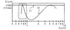
- FIG. 2is a graph illustrating the characteristic curve C1 in the light source device 10 according to the first embodiment.
- the horizontal axisrepresents the wavelength ⁇ ( ⁇ m) of one photon in photon pairs G1 and G2.
- the vertical axisrepresents the polarization period ⁇ ( ⁇ m) in the PP crystal element 12.
- the characteristic curve C1shows the wavelength of a photon satisfying the equation (1), assuming that the polarization period ⁇ is variable (fixing the excitation wavelength ⁇ p).
- the characteristic curve C1has a valley portion C10 that is partially convex downward between the near infrared region (NIR) and the mid-infrared region (MIR), and the valley portion C10. Outside of, it is generally convex upwards.
- the characteristic curve C1 as described abovehas a near-infrared peak wavelength ⁇ na and a boundary wavelength ⁇ a with respect to a straight line L1 showing a fixed value of the polarization period ⁇ within the range of ⁇ min ⁇ ⁇ max. It has four intersections p1, p2, p3, and p4 before and after each of the mid-infrared peak wavelength ⁇ ma. These four intersections p1 to p4 correspond to two photon pairs G1 and G2 satisfying the equation (1) by being paired with each other according to the law of conservation of energy and the like.
- intersection p1 before the near-infrared peak wavelength ⁇ na and the intersection p4 after the mid-infrared peak wavelength ⁇ macorrespond to the first photon pair G1 and after the near-infrared peak wavelength ⁇ na.
- the intersection p2 and the intersection p3 before the mid-infrared peak wavelength ⁇ macorrespond to the second photon pair G2. That is, the pair of wavelengths ⁇ n1 and ⁇ m1 indicated by the two intersections p1 and p4 outside the valley portion C10 and the pair of wavelengths ⁇ n2 and ⁇ m2 indicated by the two intersections p2 and p3 inside the valley portion C10 are the theory of equation (1), respectively. Construct a solution.
- the first and second photon pairs G1 and G2 satisfying the pseudo-phase matching conditionare obtained, and the first and second photon pairs G1 and G2 in the near infrared region can be obtained.
- a quantum entangled two-photon state with wavelengths ⁇ n1 and ⁇ n2 and wavelengths ⁇ m1 and ⁇ m2 in the mid-infrared regioncan be realized.
- the setting range of the polarization period ⁇ as described aboveis less than the maximum value ⁇ max and larger than the minimum value ⁇ min.
- the inventor of the present applicationhas also confirmed the range in which the excitation wavelength ⁇ p related to the above-mentioned quantum entangled two-photon state can be set. This point will be described with reference to FIGS. 3 and 4.
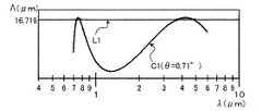
- FIG. 3illustrates a characteristic curve C1 when the excitation wavelength ⁇ p is longer than that in the case of FIG.
- FIG. 4illustrates a characteristic curve C1 when the excitation wavelength ⁇ p is shorter than that in the case of FIG.
- the excitation wavelength ⁇ p0.85 ⁇ m was set
- the excitation wavelength ⁇ p0.6 ⁇ m was set.
- the valley portion C10 of the characteristic curve C1is smaller than that in the case of FIG. 2, and the setting range ⁇ max to ⁇ min of the polarization period ⁇ is narrowed. Therefore, in the light source device 10 of the present embodiment, the excitation wavelength ⁇ p is preferably 0.85 ⁇ m or less. If the excitation wavelength ⁇ p is further lengthened, the valley portion C10 disappears, and the peak wavelengths ⁇ na, ⁇ ma and the boundary wavelength ⁇ a are degenerated. In this case, the theoretical solution of the second photon vs. G2 disappears, and the above-mentioned quantum entangled two-photon state cannot be taken.
- the absorption wavelengthis on the longer wavelength side than 5 ⁇ m. Therefore, from the viewpoint of keeping the generation efficiency of each photon pair G1 and G2 uniform in the quantum entangled two-photon state, it is desirable that the longest wavelength ⁇ m1 of the first and second photon pairs G1 and G2 is 5 ⁇ m or less.
- the longest wavelength ⁇ m1 in the first and second photon pairs G1 and G2is also set to 5 ⁇ m or less. It is possible. Therefore, in the light source device 10 of the present embodiment, it is desirable that the excitation wavelength ⁇ p is 0.6 ⁇ m or more. If the excitation wavelength ⁇ p is made shorter than this, it becomes difficult to set the wavelength ⁇ m1 to 5 ⁇ m or less.
- the light source device 10 of the present embodimentfunctions in the range of the excitation wavelength ⁇ p of 0.6 ⁇ m to 0.85 ⁇ m. Further, the light source device 10 of the present embodiment can be applied to an application in which the above generation efficiency is not particularly considered.
- the excitation wavelength ⁇ pis set so that the characteristic curve C1 has the valley portion C10
- the polarization period ⁇is set so as to pass between the maximum value ⁇ max and the minimum value ⁇ min with respect to the valley portion C10
- the light source device 10sets the light source device 10. It may be configured.
- the inventor of the present applicationhas also confirmed the theoretical solution of photons vs. G1 and G2 emitted from the coaxial direction at various angles ⁇ .
- the light source device 10 of the present embodimentcan emit a wide band of light within a range of a relatively small finite angle. This point will be described with reference to FIG.
- FIG. 5is a graph illustrating the radiation characteristic curve C2 in the light source device 10 according to the present embodiment.
- the numerical calculation of the equation (1)was performed for various angles ⁇ .
- the radiation characteristic curve C2shows the relationship between the angle ⁇ and the wavelength when one photon in the photon pair G1 and G2 satisfying the equation (1) is emitted in various directions. As shown in FIG. 5, the radiation characteristic curve C2 has a mid-infrared peak portion C20 and a near-infrared peak portion C21.
- the light source device 10 of this examplemid-infrared light having a continuous band over a wide band with a wavelength of 2 ⁇ m to 5 ⁇ m is radiated in a relatively small angle range of about 5 ° from the coaxial direction.
- the laser light source 11is used as the light source device 10, and the spot diameter of the emitted light can be easily narrowed down.
- the light source device 10may radiate light to an external condensing lens, or may be integrally configured with the condensing lens.
- the light source device 10 of the present embodimentcan be used as a wideband mid-infrared light source applicable to various applications.
- medium redhaving a continuous band from the wavelength ⁇ m1 of the first photon vs. G1 to the wavelength ⁇ m2 of the second photon vs. G2 in the mid-infrared region when emitting in the coaxial direction. External light is obtained in radiation at a finite angle ⁇ .
- a bandis not limited to the above example, and can be controlled according to settings such as the polarization period ⁇ and the excitation wavelength ⁇ p.
- the near-infrared peak portion C21extends from the wavelength ⁇ n1 of the first photon pair G1 to the wavelength ⁇ n2 of the second photon pair G2 in the near-infrared region in the coaxial direction.
- the wavelength ⁇ n1 of the first photon vs. G1increases, while the wavelength ⁇ n2 of the second photon vs. G2 decreases.
- the light source device 10 of the present embodimentcan emit infrared light having a continuous band not only in the mid-infrared region but also in the near-infrared region in a relatively small angle range.
- 6A to 6Dare graphs showing the theoretical calculation of the polarization period dependence in the light source device 10 of the present embodiment.
- 7A-7Dare graphs showing the experimental results of polarization cycle dependence.
- FIGS. 6B, 6C, and 6Dexemplify the states in which the polarization periods ⁇ are 16.923 ⁇ m, 16.821 ⁇ m, and 16.719 ⁇ m ( ⁇ max), respectively.
- 7A, 7B, 7C and 7Dshow the wavelength spectra of the experimental results corresponding to FIGS. 6A, 6B, 6C and 6D, respectively.
- a CW type semiconductor laser(output 200 mW) having the above excitation wavelength ⁇ p as the oscillation wavelength of the laser light was used as the laser light source 11, and the periodic polarization Mg-added LiTaO 3 crystal was used as the PP crystal element 12.
- PPSLTa fan-out type PPSLT (manufactured by Oxide Corporation) was used.
- the laser beamwas irradiated so as to pass through the corresponding polarization period ⁇ , and the wavelength spectrum of the light emitted from the PPSLT in the coaxial direction within a permissible angle of 1 ° was measured in the near infrared region.
- 8A to 8Dare graphs showing the theoretical calculation of the angle period dependence in the light source device 10 of the present embodiment.
- 9A-9Dare graphs showing the experimental results of the angle period dependence.
- the characteristic curves C1 at various angles ⁇were numerically calculated at the same excitation wavelength ⁇ p as in FIGS. 6A to 6D.
- the state of FIG. 8D and the state of FIG. 6Dare the same.
- 9A, 9B, 9C and 9Dshow the wavelength spectra of the experimental results corresponding to FIGS. 8A, 8B, 8C and 8D, respectively.
- FIGS. 9A-9Dan experiment was conducted to confirm the numerical calculation of FIGS. 8A-8D in the same environment as in FIGS. 7A-7D.
- FIGS. 9A to 9Dlight for an angle range of 0.9 ° from the angle ⁇ corresponding to FIGS. 8A to 8D was measured for the wavelength spectrum.
- FIGS. 9D, 9C, 9B, and 9Ait was confirmed that the two fluorescence peaks approached as the angle ⁇ was increased.
- the polarization period dependence and angle dependence of the wavelengths ⁇ n1 and ⁇ n2 of the first and second photon pairs G1 and G2were confirmed in the near infrared region. From this, it can be theoretically understood that light having the corresponding wavelengths ⁇ m1 and ⁇ m2 can be obtained at the same time in the mid-infrared region, respectively. Further, the theoretical calculation of the coherent length L in each case was about several cm or more. From this, a PP crystal element 12 having a size L12 having a coherent length L or less can be easily obtained in practical use.
- the refractive index n ( ⁇ , T) of the PP crystal element 12depends on the temperature T, the temperature dependence of the characteristic curve C1 can be theoretically grasped. Therefore, by appropriately setting the temperature T of the PP crystal element 12 in the light source device 10, for example, setting it between 0 degrees Celsius and 300 degrees Celsius, it becomes easy to generate two types of photon pairs G1 and G2. It is also possible.
- the light source device 10includes a laser light source 11 which is an example of a light source that generates an excitation light Lp having an excitation wavelength ⁇ p, and a PP crystal element 12 which is an example of a pseudo-phase matching element. To be equipped.
- the PP crystal element 12is arranged so that the excitation light Lp is incident from the laser light source 11, and is composed of a crystal having a polarization period ⁇ in which the polarization is periodically reversed.
- the first pseudo-phase matching condition defined in the PP crystal element 12is emitted from the PP crystal element 12 in response to the incident of the excitation light Lp, based on the polarization period ⁇ along the optical axis of the excitation light Lp and the excitation wavelength ⁇ p. Is satisfied by the first photon pair G1 and is satisfied by the second photon pair G2 that emits in the same direction as the first photon pair G1 based on the polarization period ⁇ and the excitation wavelength ⁇ p common to the first photon pair G1. NS.
- the first photon pair G1has a wavelength ⁇ n1 (first wavelength) within the range of the first wavelength band (for example, the near infrared region) and a second wavelength band (for example, medium red) different from the first wavelength band. It has ⁇ m1 (second wavelength) within the range of (outer region).
- the second photon pair G2has a wavelength ⁇ n2 (third wavelength) different from the wavelength ⁇ n1 within the range of the first wavelength band and a wavelength ⁇ m2 (fourth wavelength) different from the wavelength ⁇ m1 within the range of the second wavelength band. ) And.
- the laser light source 11has an excitation wavelength ⁇ p and a polarization period ⁇ such that the first and second photon pairs G1 and G2 having various wavelengths ⁇ n1 to ⁇ m2 satisfy the pseudo-phase matching condition.
- photon pairs having a plurality of wavelengthscan be generated.
- the first wavelength bandmay have an upper limit value such as the boundary wavelength ⁇ a, and the second wavelength band is set at the upper limit value or more of the first wavelength band. It may be good (see FIG. 2).
- the third wavelength ⁇ n2 due to the second photon pair G2is longer than the first wavelength ⁇ n1 due to the first photon pair G1 within the range of the first wavelength band.
- the fourth wavelength ⁇ m2 due to the second photon pair G2is shorter than the second wavelength ⁇ n2 due to the first photon pair G1 within the range of the second wavelength band. Since such a second photon pair G2 exists separately from the first photon pair G1, the quantum entangled two-photon state can be realized.
- the first wavelength bandis, for example, a near infrared region, for example, a wavelength of 700 to 900 nm.
- the second wavelength bandis, for example, a mid-infrared region, for example, a wavelength of 2 to 5 ⁇ m.
- the photons Gn1 and Gn2 in the near infrared region and the photons Gm1 and Gm2 in the mid-infrared regionare optically easy. Since it can be separated into two, a system for quantum information can be easily constructed.
- the corresponding photons Gm1 and Gm2 in the mid-infrared regioncan be easily detected.
- the band of light emitted from the PP crystal element 12may include a wide band in the mid-infrared region having a wavelength of 2 ⁇ m to 5 ⁇ m.
- the first photon pair G1may include two photons Gn1 and Gm1 having the same polarization direction as each other.
- the second photon pair G2may include two photons Gn2, Gm2 having the same polarization direction as the first photon pair G1.
- the polarization directions of the first and second photon pairs G1 and G2may be the same as the polarization directions of the excitation light Lp.
- a quantum entangled two-photon statecan be realized.
- a filter in a quantum entangled two-photon statecan be easily provided based on the polarization direction.
- At least one of the temperatures of the PP crystal element 12may be set. For example, by changing the direction of the optical axis of the excitation light Lp, the magnitude of the polarization period ⁇ along the optical axis of the excitation light Lp changes. From this, it is possible to make substantially the same adjustment as when the polarization period ⁇ of the PP crystal element 12 is changed.
- the pseudo-phase matching conditionis represented by the above-mentioned equation (1).
- ⁇ pis an angular frequency corresponding to the excitation wavelength ⁇ p
- ⁇ nis an angular frequency corresponding to the first wavelength or the third wavelength
- ⁇ mis an angular frequency corresponding to the second wavelength or the fourth wavelength.
- kpis the wavelength vector of the photon having the angular frequency ⁇ p
- knis the wavelength vector of the photon having the angular frequency ⁇ n
- kmis the wavelength vector of the photon having the angular frequency ⁇ n
- ⁇is the polarization period ⁇ .
- eis a reference vector indicating the orientation in the crystal
- ⁇ kis a vector indicating a mismatch.
- the crystal used for the PP crystal element 12is a LiTaO 3 crystal.
- the excitation wavelength ⁇ pcan be set within the range of 0.6 ⁇ m or more and 0.85 ⁇ m or less.
- FIG. 10is a graph showing the theoretical calculation of the polarization period dependence in the light source device 10 of the second embodiment.
- FIG. 11is a graph showing the theoretical calculation of the angle dependence in the light source device 10 of the present embodiment.
- the vertical axis of FIG. 10is the polarization period ⁇ ( ⁇ m)
- the horizontal axis of FIG. 11is the angle ⁇ (°) of the emitted light.
- the wavelength ⁇ m ( ⁇ m) in the mid-infrared regionis shown on the upper side of each figure, and the wavelength ⁇ n (nm) in the near-infrared region is shown on the lower side.
- the photon corresponding to the mid-infrared light in each photon pair G1 and G2may be referred to as an idler photon, and the photon corresponding to the near-infrared light may be referred to as a signal photon.
- the pseudo phase matching conditionis satisfied.
- FIG. 12is a diagram illustrating optimization of the excitation wavelength ⁇ p in the light source device 10 of the present embodiment.
- the vertical axis of FIG. 12indicates the excitation wavelength ⁇ p, and the horizontal axis indicates the wavelength ⁇ m of the idler photon.
- the region R1 in which the above-mentioned entangled two-photon state pseudo-phase matching condition is solved at various excitation wavelengths ⁇ p and the solution is obtainedis shown.
- parameterssuch as the polarization period ⁇ and the numerical aperture NA were made variable for each excitation wavelength ⁇ p.
- FIG. 13shows a configuration example of the experimental light source device 10 in this embodiment.
- the light source device 10in addition to the laser light source 11 and the PP crystal element 12, the light source device 10 has a lens 13 arranged between the laser light source 11 and the PP crystal element 12 and an emission side (+ Z side) of the PP crystal element 12. It includes an aperture 14, a lens 15, a wavelength filter 16 and a lens 17 arranged in order.
- the light source device 10 of this configuration exampleis connected to the silicon CCD 20 via a transmission optical system such as an optical fiber.
- the lens 13has, for example, a focal length of 100 mm, and guides the excitation light Lp from the laser light source 11 to the PP crystal element 12.
- the diaphragm 14regulates the light emitted from the PP crystal element 12 at various numerical apertures set in advance.
- the lens 15has, for example, a focal length of 200 mm, guides the transmissible light among the light passing through the diaphragm 14, and blocks, for example, mid-infrared light.
- the wavelength filter 16selectively passes light having a wavelength larger than, for example, 700 nm, and blocks, for example, excitation light Lp.
- the lens 17has, for example, a focal length of 50 mm, and collects light that has passed through the wavelength filter 16 (for example, near-infrared light) on one end of a transmission optical system or the like.
- the silicon CCD 20is connected to the other end of the transmission optical system, and can observe the signal photon among the photon pairs of the idler photon and the signal photon generated in the PP crystal element 12.
- the wavelength band of the signal photonmay be appropriately set to a wavelength band that can be detected by a silicon detector such as a silicon CCD20, or may include a visible light region.
- the wavelength band of the idler photon in this caseis set so as to correspond to the wavelength band of the signal photon, for example, in the infrared region.
- FIG. 14shows a configuration example of the PP crystal element 12 in the light source device 10 of the present embodiment.
- the PP crystal element 12 of this configuration exampleis composed of a fan-out type PPSLT, and has, for example, a size of 11 mm in the Z direction and a size of 5 mm in the X direction.
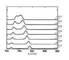
- FIG. 15is graphs S11 to S17 showing the experimental results of the polarization cycle dependence in the light source device 10 of the second embodiment.
- the spectrum of the wavelength ⁇ n in the near infrared region corresponding to the signal photonwas measured while changing the polarization period ⁇ for the coaxial process, as in the experiments of FIGS. 7A to 7D.
- FIG. 16is a graph showing the correspondence between the theoretical calculation of the polarization cycle dependence and the experimental results in the present embodiment.
- the theoretical calculation of the polarization period dependence for the coaxial processis as shown in the experimental data (Experimental data) obtained as the experimental result of FIG. 15 and FIG. It was confirmed that they were well aligned.
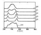
- FIG. 17is graphs S20 to S25 showing the experimental results of the angle dependence in the light source device 10 of the second embodiment.
- the numerical aperture NA0.07
- the spectrum of the wavelength ⁇ n in the near infrared regionwas measured for each emission angle range as in the experiments of FIGS. 9A to 9D.
- graph S20is a wavelength spectrum of signal photons when the angle range is set to ⁇ ⁇ 0.66 °.
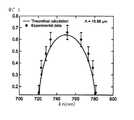
- FIG. 18is a graph showing the correspondence between the theoretical calculation of the angle dependence and the experimental result in the present embodiment. In the present embodiment, it was confirmed that the theoretical calculation of the angle dependence is also well matched with the experimental data obtained as the experimental result of FIG. 17 as shown in FIG.
- the PP crystal element 12 using the LiTaO 3 crystalhas been illustrated as an example of the pseudo-phase matching element, but the present disclosure is not particularly limited thereto.
- the pseudo-phase matching elementcan be composed of various crystals provided with a periodic polarization structure, and may be composed of, for example, a lithium niobate (LiNbO 3 ) crystal.
- LiNbO 3lithium niobate
- the excitation wavelength ⁇ pcan be set to 0.65 ⁇ m or more and 0.95 ⁇ m or less.
- the pseudo-phase matching element of the present embodimentmay be composed of crystals such as potassium niobate (KNbO 3 ) or potassium titanate (KTIOPO 4).
- KNbO 3potassium niobate
- KTIOPO 4potassium titanate
- FIG. 19shows the theoretical calculation of the polarization period dependence in the modified example of the light source device as described above.
- FIG. 20shows the theoretical calculation of the angle dependence in the light source device of this modification.
- the light source device of this modificationhas a configuration similar to that of the light source devices 10 of the first and second embodiments, and includes a PPLN pseudo-phase matching element instead of the PPSLT pseudo-phase matching element.
- FIG. 19illustrates a characteristic curve C3 (PPLN QPM curve) when the pseudo-phase matching condition is satisfied in PPLN, similarly to the characteristic curve C1 in FIG.
- FIG. 20illustrates a portion corresponding to an idler photon in the radiation characteristic curve C4 similar to the radiation characteristic curve C2 in FIG. 5 in the above case.
- the characteristic curve C3 having two peaks in different wavelength bandscan be obtained, and the quantum entangled two-photon state can be realized as in the first and second embodiments. confirmed.
- the PP crystal element 12 having a constant polarization period ⁇is illustrated as an example of the pseudo-phase matching element.
- the polarization period ⁇ of the pseudo-phase matching elementmay change inside the pseudo-phase matching element.
- a pseudo-phase matching elementmay be configured by a chirp-type periodic polarization structure in which the polarization period ⁇ changes along the coaxial direction. In this case, the band of light emitted in the coaxial direction can be widened according to the change in the polarization period ⁇ .
- the periodic polarization structure of the pseudo-phase matching elementmay have various configurations, for example, not limited to the chirp type, but may be a fan-out type, a single grating type, a multi-grating type, a hybrid type, or the like. There may be.
- the laser light source 11is exemplified as an example of the light source in the light source device 10.
- the light source in the light source device 10may be composed of a combination of a laser light source and various wavelength conversion elements. Such a wavelength conversion element may be integrally configured with, for example, the PP crystal element 12.
- the light source in the light source device 10is not necessarily limited to the laser light source, and may include various solid-state light sources.
- the excitation wavelength ⁇ p in the light source device 10is not particularly limited to the visible region, and can be appropriately set in various wavelength bands according to the design.
- the quantum entangled two-photon state due to the phase matching of type-0has been described.
- the present embodimentis not limited to type-0, and for example, phase matching of type-II or type-I can also be used.
- the same theoretical calculation as in the first embodimentcan be applied by using the refractive index and the like in each polarization direction, and various parameters of the light source device 10 can be appropriately designed.
- the present disclosureis applicable to, for example, quantum information technology, but is not limited thereto.
- the present disclosureis also applicable to various fields such as spectroscopy / analysis using infrared rays.
Landscapes
- Physics & Mathematics (AREA)
- Nonlinear Science (AREA)
- General Physics & Mathematics (AREA)
- Optics & Photonics (AREA)
- Optical Modulation, Optical Deflection, Nonlinear Optics, Optical Demodulation, Optical Logic Elements (AREA)
Abstract
Description
Translated fromJapanese本開示は、例えば量子的に相関した光子の対を生成する光源装置に関する。The present disclosure relates to, for example, a light source device that generates quantum-correlated photon pairs.
近年、量子テレポーテーションや量子センサを構築するための光を用いた量子情報の基礎技術として、量子相関によりもつれ合った光子対を生成する技術が研究されている。In recent years, as a basic technology of quantum information using light for constructing quantum teleportation and quantum sensors, a technology for generating entangled photon pairs by quantum correlation has been studied.
特許文献1は、非縮退の偏光量子もつれ光子対を効率よく簡便に生成することを目的とした非縮退偏光量子もつれ光子対生成装置を開示している。この装置は、互いに周期が異なる第1及び第2周期分極反転構造をその内部に形成した量子もつれ光子対生成体と、第1周期分極反転構造を通過した後に第2周期分極反転構造を通過するように光を量子もつれ光子対生成体に入射させる入射手段とを備える。第1周期分極反転構造の周期は、ある角周波数ω1を持たせた光子が第1の偏光を有し、別の角周波数ω2を持たせた光子が第2の偏光を有するように調整される。第2周期分極反転構造の周期は、角周波数ω1の光子が第2の偏光を有し、角周波数ω2の光子が第1の偏光を有するように調整される。
特許文献1の装置では、角周波数ω1,ω2と第1及び第2の偏光とのもつれ合いによる2種類の光子対が、量子もつれ光子対生成体の中で第1周期分極反転構造が設けられた場所と、第2周期分極反転構造が設けられた場所とにおいて別々に生成されることから、量子的なもつれかどうかには議論がある。又、第1及び第2周期分極反転構造の各々の周期を精密に調整した装置構成を要する一方で、角周波数ω1,ω2の違いは僅かであり、生成される光子対の波長帯は近赤外領域中の限られた一部に留まる。In the apparatus of
本願発明者は、こうした光子対の生成技術について鋭意研究を重ね、従来技術とは異なった複数の波長帯による新規の量子もつれ2光子状態を見出した。この知見から、本願発明者は、新規の量子もつれ光源だけでなく広帯域光源としても活用できる技術を考案するに到った。The inventor of the present application has conducted extensive research on such a photon pair generation technique, and has found a new quantum entangled two-photon state with a plurality of wavelength bands different from the conventional technique. From this knowledge, the inventor of the present application has come up with a technique that can be utilized not only as a novel quantum entangled light source but also as a wideband light source.
本開示は、簡単な装置構成において複数の波長を有する光子対を生成できる光源装置を提供する。The present disclosure provides a light source device capable of generating photon pairs having a plurality of wavelengths in a simple device configuration.
本開示に係る光源装置は、励起波長を有する励起光を生成する光源と、光源から励起光が入射するように配置され、周期的に分極が反転する分極周期を有する結晶で構成される擬似位相整合素子とを備える。擬似位相整合素子において規定される擬似位相整合条件が、励起光の光軸に沿った分極周期及び励起波長に基づき、励起光の入射に応じて擬似位相整合素子から出射する第1の光子対により充足され、且つ第1の光子対と共通の分極周期及び励起波長に基づき、第1の光子対と共通の方向に出射する第2の光子対により充足される。第1の光子対は、第1の波長帯の範囲内の第1波長と、第1の波長帯とは異なる第2の波長帯の範囲内の第2波長とを有する。第2の光子対は、第1の波長帯の範囲内で第1波長とは異なる第3波長と、第2の波長帯の範囲内で第2波長とは異なる第4波長とを有する。The light source device according to the present disclosure is a pseudo-phase composed of a light source that generates excitation light having an excitation wavelength and a crystal having a polarization period in which excitation light is incident from the light source and the polarization is periodically reversed. It is equipped with a matching element. The pseudo-phase matching condition defined in the pseudo-phase matching element is based on the polarization period and excitation wavelength along the optical axis of the excitation light, and is determined by the first photon pair emitted from the pseudo-phase matching element in response to the incident of the excitation light. It is satisfied and is satisfied by the second photon pair that emits in the same direction as the first photon pair, based on the polarization period and excitation wavelength common to the first photon pair. The first photon pair has a first wavelength within the range of the first wavelength band and a second wavelength within the range of the second wavelength band different from the first wavelength band. The second photon pair has a third wavelength that is different from the first wavelength within the range of the first wavelength band and a fourth wavelength that is different from the second wavelength within the range of the second wavelength band.
本開示によると、第1から第4の波長を有する第1及び第2の光子対が、擬似位相整合条件を充足するような励起波長及び分極周期を有する光源及び擬似位相整合素子という簡単な装置構成において、複数の波長を有する光子対を生成できる光源装置を提供することができる。According to the present disclosure, a simple device such as a light source and a pseudo-phase matching element having an excitation wavelength and a polarization period such that the first and second photon pairs having the first to fourth wavelengths satisfy the pseudo-phase matching condition. In the configuration, it is possible to provide a light source device capable of generating photon pairs having a plurality of wavelengths.
以下、添付の図面を参照して本開示に係る光源装置の実施の形態を説明する。なお、以下の各実施形態において、同様の構成要素については同一の符号を付している。Hereinafter, embodiments of the light source device according to the present disclosure will be described with reference to the attached drawings. In each of the following embodiments, the same reference numerals are given to the same components.
(実施形態1)
実施形態1では、量子もつれ光源を非常に簡単な構成で実現し、且つ中赤外領域等の広帯域光源としても機能する光源装置の一例について説明する。(Embodiment 1)
In the first embodiment, an example of a light source device that realizes a quantum entangled light source with a very simple configuration and also functions as a wideband light source in the mid-infrared region will be described.
1.装置構成
実施形態1に係る光源装置の構成について、図1を用いて説明する。図1は、本実施形態に係る光源装置10の構成を例示する模式図である。1. 1. Device Configuration The configuration of the light source device according to the first embodiment will be described with reference to FIG. FIG. 1 is a schematic diagram illustrating the configuration of the
本実施形態に係る光源装置10は、例えば図1に示すように、レーザ光源11と、PP(周期分極)結晶素子12とを備える。レーザ光源11は、PP結晶素子12に供給する励起光Lpを生成する光源の一例である。PP結晶素子12は、周期的に分極を反転させた結晶で構成される擬似位相整合素子の一例である。The
本実施形態の光源装置10は、レーザ光源11及びPP結晶素子12という簡単な装置構成において、本願発明者の鋭意研究により見出された複数の波長帯による量子もつれ2光子状態(後述)を実現する。これにより、本実施形態の光源装置10は、新規の量子もつれ光源および広帯域光源として機能する。The
レーザ光源11は、例えば各種半導体レーザで構成される。例えば、レーザ光源11は、予め設定された励起波長λpにピーク波長を有するレーザ光を励起光Lpとして生成する。レーザ光によると、励起光Lpにコヒーレント性を持たせることができる。励起波長λpは、本実施形態では可視領域において設定され、例えばλp=0.6μm~0.85μmである。The
励起光Lpは、例えばレーザ光源11を出射後にPP結晶素子12に入射してから進行する方向に沿った光軸を有する。以下、光源装置10における励起光Lpの光軸の方向をZ方向とし、Z方向に垂直で且つ互いに直交する2方向をX,Y方向とする。又、励起光Lpに含まれる光子Gpを「励起光子Gp」という場合がある。The excitation light Lp has, for example, an optical axis along a direction in which the
PP結晶素子12は、例えばタンタル酸リチウム(LiTaO3)の結晶に周期分極構造を設けて構成される。周期分極構造は、特定の方向に沿って結晶の分極が、予め設定された分極周期Λ毎に反転した構造である。本実施形態の光源装置10では、PP結晶素子12が、周期分極構造の方向をZ方向に向けて配置される。分極周期Λは、本実施形態ではPP結晶素子12内で一定の値に設定され、例えば16μm~25μmである。また、PP結晶素子12のサイズL12は、所謂コヒーレント長Lよりも短く設定され、例えば数cmである。The
以上のように構成される光源装置10によると、図1に示すように、レーザ光源11からの励起光Lpの入射に応じてPP結晶素子12内で量子もつれ2光子状態が生じ、例えば同じ場所で2種類の光子対G1,G2が生成され得る。According to the
2.量子もつれ2光子状態について
本実施形態の光源装置10における量子もつれ2光子状態について、図1を用いて説明する。2. Quantum entangled two-photon state The quantum entangled two-photon state in the
量子もつれ2光子状態は、例えば励起光Lpと同軸方向すなわちZ方向に出射する光に関して、次式(10)のように表される。
|ψ>=|ωn1>|ωm1>+|ωn2>|ωm2> …(10)The quantum entangled two-photon state is expressed by the following equation (10) with respect to light emitted in the coaxial direction, that is, in the Z direction, for example, with respect to the excitation light Lp.
| ψ > = | ωn1 >| ωm1 > + | ωn2 >| ωm2 >… (10)
上式(10)において、左辺は量子もつれ2光子状態の波動関数を示す。右辺の第1項は、第1の光子対G1による2光子状態を示し、第2項は第2の光子対G2による2光子状態を示す。In the above equation (10), the left side shows the wave function of the quantum entangled two-photon state. The first term on the right side shows the two-photon state by the first photon vs. G1, and the second term shows the two-photon state by the second photon vs. G2.
2光子状態は、パラメトリック過程の一種であるパラメトリック下方変換等により、1つの励起光子Gpが、2つの光子からなる光子対に変換された状態である。2光子状態は、例えば上式(10)の第1項(又は第2項)のように、光子対G1(又はG2)における1つ目の光子Gn1(又はGn2)の量子状態と、2つ目の光子Gm1(又はGm2)の量子状態との積により記述される。本実施形態では、所謂type-0の位相整合を想定しており、励起光子Gpの偏光状態と、各光子対G1,G2における各々の光子Gn1~Gm2の偏光状態とは同じである。The two-photon state is a state in which one excited photon Gp is converted into a photon pair consisting of two photons by parametric downward conversion, which is a kind of parametric process. There are two two-photon states, for example, the quantum state of the first photon Gn1 (or Gn2) in the photon pair G1 (or G2), as in the first term (or second term) of the above equation (10). It is described by the product of the photon Gm1 (or Gm2) of the eye with the quantum state. In this embodiment, so-called type-0 phase matching is assumed, and the polarization state of the excited photon Gp is the same as the polarization state of each photon Gn1 to Gm2 in each photon pair G1 and G2.
量子もつれ2光子状態は、例えば式(10)に示すように、複数の2光子状態の和つまり重ね合わせで記述される。量子もつれ2光子状態によると、1つの励起光子Gpから生成される光子対の候補として複数の2光子状態が存在することから、例えば1つの光子対が生成されたときに、当該光子対のうちの一方の光子の状態が観測されるまで他方の光子の状態は判明しない。その一方で、当該光子対のうちの一方の光子の状態が観測されると、他方の光子の状態も同時に判明することとなる。The quantum entangled two-photon state is described by, for example, as shown in equation (10), the sum or superposition of a plurality of two-photon states. According to the entangled two-photon state, there are a plurality of two-photon states as candidates for the photon pair generated from one excited photon Gp. Therefore, for example, when one photon pair is generated, among the photon pairs. The state of one photon is unknown until the state of one photon is observed. On the other hand, when the state of one of the photon pairs is observed, the state of the other photon is also known at the same time.
式(10)において、ωn1,ωn2は各光子対G1,G2における1つ目の光子Gn1,Gn2の角周波数であり、ωm1,ωm2は他方の2つ目の光子Gm1,Gm2の角周波数である。本実施形態において、角周波数ωn1,ωn2はそれぞれ近赤外領域において別々の波長λn1,λn2に対応し、角周波数ωm1,ωm2はそれぞれ中赤外領域において別々の波長λm1,λm2に対応する。In equation (10), ωn1 and ωn2 are the angular frequencies of the first photon Gn1 and Gn2 in each photon pair G1 and G2, and ωm1 and ωm2 are the angular frequencies of the other second photon Gm1 and Gm2. .. In the present embodiment, the angular frequencies ωn1 and ωn2 correspond to different wavelengths λn1 and λn2 in the near infrared region, and the angular frequencies ωm1 and ωm2 correspond to different wavelengths λm1 and λm2 in the mid-infrared region, respectively.
従来の量子もつれ2光子状態に関する研究は、近赤外領域において盛んに行われている。また、一般的に良く知られた2光子状態には、光子対における各光子の波長が互いに同一の縮退状態がある。特許文献1の縮退偏光量子もつれ光子対生成装置は、2光子状態において偏光状態の違いに伴い各光子の波長を、1.58μmと1.52μmというように近赤外領域の範囲内で僅かに異ならせている。Conventional research on quantum entangled two-photon states is being actively conducted in the near-infrared region. Further, in the generally well-known two-photon state, there is a degenerate state in which the wavelengths of the photons in the photon pair are the same as each other. The reduced polarization quantum entangled photon pair generator of
本実施形態の量子もつれ2光子状態は、各光子対G1,G2において近赤外領域の光子Gn1,Gn2と中赤外領域の光子Gm1,Gm2とがペアリングされた新規のもの(理論解)である。本願発明者は、近赤外領域だけでなく中赤外領域にまで及ぶ広範囲に亘って、励起光Lpの入射に応じてPP結晶素子12中で量子もつれ2光子状態を生じ得る理論解を探索することにより、本実施形態の光源装置10を想到するに到った。The quantum entangled two-photon state of the present embodiment is a novel one in which photons Gn1 and Gn2 in the near-infrared region and photons Gm1 and Gm2 in the mid-infrared region are paired in each photon pair G1 and G2 (theoretical solution). Is. The inventor of the present application has searched for a theoretical solution that can generate a quantum entangled two-photon state in the
2-1.擬似位相整合条件について
量子もつれ2光子状態は理論的に、次式(1a),(1b)のような擬似位相整合条件を充足する光子対が複数、在る場合に実現される。2-1. Pseudo-phase matching condition The quantum entangled two-photon state is theoretically realized when there are a plurality of photon pairs satisfying the pseudo-phase matching condition as in the following equations (1a) and (1b).

擬似位相整合条件は、光子対の基となる励起光子Gpと、光子対との(平面波解等における)位相の整合性から要求される。以下では式(1a),(1b)の総称を式(1)という場合がある。The pseudo-phase matching condition is required from the phase matching (in a plane wave solution, etc.) between the excited photon Gp, which is the basis of the photon pair, and the photon pair. In the following, the generic names of the equations (1a) and (1b) may be referred to as the equation (1).
式(1a)は、励起光子Gpと光子対とにおけるエネルギーの保存則に関し、励起波長λpに対応する角周波数ωpに基づいている。ωnは光子対における一方の光子の角周波数であり、ωmは同光子対における他方の光子の角周波数である。本実施形態において、ωn=ωn1又はωn2であり、ωm=ωm1又はωm2である。Equation (1a) is based on the angular frequency ωp corresponding to the excitation wavelength λp with respect to the energy conservation law between the excitation photon Gp and the photon pair. ωn is the angular frequency of one photon in the photon pair and ωm is the angular frequency of the other photon in the same photon pair. In this embodiment, ωn = ωn1 or ωn2, and ωm = ωm1 or ωm2.
式(1b)は、励起光子Gpと光子対とにおける運動量の保存則に関する。上式(1b)に上付きで表記した矢印「→」は、以下では省略するが、空間座標(X,Y,Z)における3次元ベクトルを示す。kpは、励起光子Gpの波数ベクトルを示す。knは、光子対における角周波数ωnの光子の波数ベクトルを示し、kmは、同光子対における角周波数ωmの光子の波数ベクトルを示す。eは、PP結晶素子12の周期分極構造の方向を示す基準ベクトルであり、絶対値|e|=1に規格化されている。Δkは、ミスマッチを示すベクトルであり、コヒーレント長Lと次式(11)の対応関係を有する(πは円周率)。
L=2π/|Δk| …(11)Equation (1b) relates to the law of conservation of momentum between the excited photon Gp and the photon pair. The arrow “→” superscripted in the above equation (1b) is omitted below, but indicates a three-dimensional vector in spatial coordinates (X, Y, Z). kp represents the wave vector of the excited photon Gp. kn indicates a wave vector of a photon having an angular frequency ωn in a photon pair, and km indicates a wave vector of a photon having an angular frequency ωm in the same photon pair. e is a reference vector indicating the direction of the periodic polarization structure of the
L = 2π / | Δk |… (11)
本実施形態では、励起光Lpの光軸すなわち励起光子Gpの進行方向をZ方向としていることから、波数ベクトルkp=(kpx,kpy,kpz)においてZ成分kpz以外のX,Y成分kpx,kpyは「0」である。又、PP結晶素子12の基準ベクトルeも、上述したようにZ方向に向いており、e=(0,0,1)である。In the present embodiment, since the optical axis of the excitation light Lp, that is, the traveling direction of the excitation photon Gp is the Z direction, the X and Y components kpx and kpy other than the Z component kpz in the wave vector kp = (kpx, kpy, kpz). Is "0". Further, the reference vector e of the
各種の角周波数ω(=ωp,ωn,ωm)と波数ベクトルk(=kp,kn,km)とは、PP結晶素子12の内部ではその屈折率n(λ,T)を用いて、次式(12)の関係を有する。
ω=c|k|/n(λ,T) …(12)The various angular frequencies ω (= ωp, ωn, ωm) and the wave vector k (= kp, kn, km) are expressed by the following equations using their refractive index n (λ, T) inside the
ω = c | k | / n (λ, T) ... (12)
上式(12)において、cは光速であり、|k|は波数ベクトルkの絶対値であり、TはPP結晶素子12の温度である。なお、各種の波長λ(=λp,λn,λm)と波数ベクトルkとは、λ=2π/|k|の関係を有する。また、真空中の角周波数ωと波長λとの対応関係は、ω=2πc/λである。In the above equation (12), c is the speed of light, | k | is the absolute value of the wave vector k, and T is the temperature of the
PP結晶素子12の屈折率n(λ,T)は、光(或いは光子)の波長λに応じて変動する特性を有する。こうした特性は、温度変動の特性と共に経験則的に知られた次式(13)のようなSellmeierの分散式により表される(非特許文献1参照)。
本願発明者は、擬似位相整合条件の式(1)に関して、PP結晶素子12の屈折率n(λ,T)の波長依存性が影響するような幅広い波長帯にわたり量子もつれ2光子状態の理論解を探索した。上式(13)におけるパラメータA~H及び温度関数b(T),c(T)としては、本実施形態のPP結晶素子12に関してSLT(リチウムタンタレート)を用いる際に、非特許文献1に従い下記の値を採用した(Tは摂氏温度)。
A=4.502483
B=0.007294
C=0.185087
D=-0.02357
E=0.073423
F=0.199595
G=0.001
H=7.99724
b(T)=3.483933×10⁻⁸(T+273.15)2
c(T)=1.607839×10⁻⁸(T+273.15)2The inventor of the present application has a theoretical solution of a quantum entangled two-photon state over a wide wavelength band in which the wavelength dependence of the refractive index n (λ, T) of the
A = 4.502483
B = 0.007294
C = 0.185087
D = -0.02357
E = 0.073423
F = 0.199595
G = 0.001
H = 7.997424
b (T) = 3.483933 ×10⁻⁸ (T + 273.15)2
c (T) = 1.607838 ×10⁻⁸ (T + 273.15)2
2-2.同軸解について
以下では、各光子対G1,G2が励起光Lpの光軸と同軸方向に出射する場合の理論解について、図2~4を用いて説明する。この場合、対応する波数ベクトルkn,kmは、kn=(0,0,|kn|),km=(0,0,|km|)となる。2-2. Coaxial solution In the following, the theoretical solution when each photon pair G1 and G2 emits in the coaxial direction with the optical axis of the excitation light Lp will be described with reference to FIGS. 2 to 4. In this case, the corresponding wave vector kn, km is kn = (0,0, | kn |), km = (0,0, | km |).
図2は、実施形態1に係る光源装置10における特性曲線C1を例示するグラフである。横軸は、光子対G1,G2における1つの光子の波長λ(μm)を示す。縦軸は、PP結晶素子12における分極周期Λ(μm)を示す。FIG. 2 is a graph illustrating the characteristic curve C1 in the
特性曲線C1は、(励起波長λpを固定して)分極周期Λが可変と仮定した際に、式(1)を充足する光子の波長を示す。図2では、励起波長λpをλp=0.76μmに設定して、擬似位相整合条件の式(1)の数値計算を行った。The characteristic curve C1 shows the wavelength of a photon satisfying the equation (1), assuming that the polarization period Λ is variable (fixing the excitation wavelength λp). In FIG. 2, the excitation wavelength λp was set to λp = 0.76 μm, and the numerical calculation of the equation (1) under the pseudo-phase matching condition was performed.
図2に例示する場合において、特性曲線C1は、近赤外領域(NIR)と中赤外領域(MIR)との間において部分的に下に凸となる谷部分C10を有し、谷部分C10の外部では全体的に上に凸である。特性曲線C1では、近赤外領域におけるピーク波長λ=λnaにて分極周期Λが極大値Λmaxとなり、且つ中赤外領域におけるピーク波長λ=λmaにて分極周期Λが極大値Λmaxとなる。又、特性曲線C1の谷部分C10では、近赤外のピーク波長λnaと中赤外のピーク波長λmaとの間の境界波長λ=λaにて分極周期Λが極小値Λminとなる。In the case illustrated in FIG. 2, the characteristic curve C1 has a valley portion C10 that is partially convex downward between the near infrared region (NIR) and the mid-infrared region (MIR), and the valley portion C10. Outside of, it is generally convex upwards. In the characteristic curve C1, the polarization period Λ has a maximum value of Λmax at the peak wavelength λ = λna in the near infrared region, and the polarization period Λ has a maximum value of Λmax at the peak wavelength λ = λma in the mid-infrared region. Further, in the valley portion C10 of the characteristic curve C1, the polarization period Λ becomes the minimum value Λmin at the boundary wavelength λ = λa between the peak wavelength λna in the near infrared and the peak wavelength λma in the middle infrared.
上記のような特性曲線C1は、図2に示すように、Λmin<Λ<Λmaxの範囲内で分極周期Λの固定値を示す直線L1に対して、近赤外のピーク波長λnaと境界波長λaと中赤外のピーク波長λmaとの各々の前後にて4交点p1,p2,p3,p4を有する。こうした4交点p1~p4は、エネルギーの保存則等から2つずつにペアリングされることにより、式(1)を充足する2つの光子対G1,G2に対応する。As shown in FIG. 2, the characteristic curve C1 as described above has a near-infrared peak wavelength λna and a boundary wavelength λa with respect to a straight line L1 showing a fixed value of the polarization period Λ within the range of Λmin <Λ <Λmax. It has four intersections p1, p2, p3, and p4 before and after each of the mid-infrared peak wavelength λma. These four intersections p1 to p4 correspond to two photon pairs G1 and G2 satisfying the equation (1) by being paired with each other according to the law of conservation of energy and the like.
具体的に、近赤外のピーク波長λna前の交点p1と中赤外のピーク波長λma後の交点p4とが第1の光子対G1に対応しており、近赤外のピーク波長λna後の交点p2と、中赤外のピーク波長λma前の交点p3とが、第2の光子対G2に対応している。即ち、谷部分C10外部の2交点p1,p4が示す波長λn1,λm1のペアと、谷部分C10内部の2交点p2,p3が示す波長λn2,λm2のペアとが、それぞれ式(1)の理論解を構成する。Specifically, the intersection p1 before the near-infrared peak wavelength λna and the intersection p4 after the mid-infrared peak wavelength λma correspond to the first photon pair G1 and after the near-infrared peak wavelength λna. The intersection p2 and the intersection p3 before the mid-infrared peak wavelength λma correspond to the second photon pair G2. That is, the pair of wavelengths λn1 and λm1 indicated by the two intersections p1 and p4 outside the valley portion C10 and the pair of wavelengths λn2 and λm2 indicated by the two intersections p2 and p3 inside the valley portion C10 are the theory of equation (1), respectively. Construct a solution.
以上のように、特性曲線C1の谷部分C10を通るような分極周期Λの設定により、擬似位相整合条件を充足する第1及び第2の光子対G1,G2が得られ、近赤外領域の波長λn1,λn2と、中赤外領域の波長λm1,λm2とによる量子もつれ2光子状態を実現できる。As described above, by setting the polarization period Λ so as to pass through the valley portion C10 of the characteristic curve C1, the first and second photon pairs G1 and G2 satisfying the pseudo-phase matching condition are obtained, and the first and second photon pairs G1 and G2 in the near infrared region can be obtained. A quantum entangled two-photon state with wavelengths λn1 and λn2 and wavelengths λm1 and λm2 in the mid-infrared region can be realized.
上記のような分極周期Λの設定範囲は、極大値Λmax未満で且つ極小値Λminよりも大きい。Λ=Λmaxになると、第1の光子対G1の波長λn1,λm1と第2の光子対G2の波長λn2,λm2とが、それぞれ縮退してしまう(λn1=λn2=λna,λm1=λm2=λma)。Λ=Λminになると、第2の光子対G2の波長λn2,λm2同士が縮退してしまう(λn1=λm2=λa)。The setting range of the polarization period Λ as described above is less than the maximum value Λmax and larger than the minimum value Λmin. When Λ = Λmax, the wavelengths λn1, λm1 of the first photon pair G1 and the wavelengths λn2, λm2 of the second photon pair G2 are degenerated (λn1 = λn2 = λna, λm1 = λm2 = λma). .. When Λ = Λmin, the wavelengths λn2 and λm2 of the second photon pair G2 are degenerated (λn1 = λm2 = λa).
本願発明者は、以上のような量子もつれ2光子状態に関する励起波長λpを設定可能な範囲についても確認した。この点について、図3,4を用いて説明する。The inventor of the present application has also confirmed the range in which the excitation wavelength λp related to the above-mentioned quantum entangled two-photon state can be set. This point will be described with reference to FIGS. 3 and 4.
図3は、図2の場合よりも励起波長λpが長い場合の特性曲線C1を例示する。図4は、図2の場合よりも励起波長λpが短い場合の特性曲線C1を例示する。具体的に、図3では励起波長λp=0.85μmに設定し、図4では励起波長λp=0.6μmに設定した。FIG. 3 illustrates a characteristic curve C1 when the excitation wavelength λp is longer than that in the case of FIG. FIG. 4 illustrates a characteristic curve C1 when the excitation wavelength λp is shorter than that in the case of FIG. Specifically, in FIG. 3, the excitation wavelength λp = 0.85 μm was set, and in FIG. 4, the excitation wavelength λp = 0.6 μm was set.
図3の場合、特性曲線C1の谷部分C10が、図2の場合よりも小さくなっており、分極周期Λの設定範囲Λmax~Λminが狭くなっている。このことから、本実施形態の光源装置10において、励起波長λpは、0.85μm以下であることが望ましい。更に励起波長λpを長くすると、谷部分C10が無くなり、各ピーク波長λna,λma及び境界波長λaが縮退してしまう。この場合、第2の光子対G2の理論解が無くなり、上述した量子もつれ2光子状態は取り得なくなる。In the case of FIG. 3, the valley portion C10 of the characteristic curve C1 is smaller than that in the case of FIG. 2, and the setting range Λmax to Λmin of the polarization period Λ is narrowed. Therefore, in the
また、図2~4においてPP結晶素子12に用いたLiTaO3においては、吸収波長が5μmよりも長波長側にある。よって、量子もつれ2光子状態において各光子対G1,G2の生成効率を均等に保つ観点からすると、第1及び第2の光子対G1,G2における最長の波長λm1が5μm以下であることが望ましい。Further, in LiTaO 3 used for the
図4の場合では、特性曲線C1において中赤外のピーク波長λmaが5μmよりも僅かに小さいことから、第1及び第2の光子対G1,G2における最長の波長λm1も、5μm以下に設定することが可能である。このことから、本実施形態の光源装置10において、励起波長λpは、0.6μm以上であることが望ましい。これよりも励起波長λpを短くすると、波長λm1を5μm以下に設定し難くなる。In the case of FIG. 4, since the peak wavelength λma in the mid-infrared region is slightly smaller than 5 μm in the characteristic curve C1, the longest wavelength λm1 in the first and second photon pairs G1 and G2 is also set to 5 μm or less. It is possible. Therefore, in the
以上のように、本実施形態の光源装置10は、励起波長λpが0.6μm~0.85μmの範囲内で機能することが確認された。又、本実施形態の光源装置10は、特に上記生成効率を考慮しない用途にも適用可能である。この場合、特性曲線C1に谷部分C10を持たせるように励起波長λpを設定し、谷部分C10に関する極大値Λmaxと極小値Λmin間を通るように分極周期Λを設定して、光源装置10が構成されてもよい。As described above, it was confirmed that the
2-3.角度依存性と広帯域光源
本願発明者は、同軸方向から種々の角度θで放射される光子対G1,G2の理論解についても確認した。本実施形態の光源装置10は、比較的小さい有限角度の範囲内で広帯域の光を放射できる。この点について、図5を用いて説明する。2-3. Angle Dependence and Wideband Light Source The inventor of the present application has also confirmed the theoretical solution of photons vs. G1 and G2 emitted from the coaxial direction at various angles θ. The
図5は、本実施形態に係る光源装置10における放射特性曲線C2を例示するグラフである。図5では、図2の場合(λp=0.76μm)において様々な角度θに関して式(1)の数値計算を行った。この際、分極周期Λは、Λ=20.6μmに設定した。FIG. 5 is a graph illustrating the radiation characteristic curve C2 in the
放射特性曲線C2は、式(1)を充足する光子対G1,G2における1光子が、種々の方向に放射される際の角度θと波長との関係を示す。放射特性曲線C2は、図5に示すように、中赤外のピーク部分C20と、近赤外のピーク部分C21とを有する。The radiation characteristic curve C2 shows the relationship between the angle θ and the wavelength when one photon in the photon pair G1 and G2 satisfying the equation (1) is emitted in various directions. As shown in FIG. 5, the radiation characteristic curve C2 has a mid-infrared peak portion C20 and a near-infrared peak portion C21.
中赤外のピーク部分C20は、上述した同軸方向(即ちθ=0°)の場合の中赤外領域における第1の光子対G1の波長λm1(本例では略5μm)から第2の光子対G2の波長λm2(本例では略2μm)までに及ぶ。角度θが0°から増えるにつれて、第1の光子対G1の波長λm1は減少する一方、第2の光子対G2の波長λm2は増大している。角度θ=5°程度に到ると、中赤外領域における各光子対G1,G2の波長λm1,λm2はピーク波長λmbに縮退している(λm1=λm2=λmb)。The mid-infrared peak portion C20 has a wavelength λm1 (approximately 5 μm in this example) of the first photon pair G1 in the mid-infrared region in the above-mentioned coaxial direction (that is, θ = 0 °) to the second photon pair. It extends to the wavelength λm2 of G2 (approximately 2 μm in this example). As the angle θ increases from 0 °, the wavelength λm1 of the first photon vs. G1 decreases, while the wavelength λm2 of the second photon vs. G2 increases. When the angle θ = 5 °, the wavelengths λm1 and λm2 of each photon pair G1 and G2 in the mid-infrared region are degenerated to the peak wavelength λmb (λm1 = λm2 = λmb).
本例の光源装置10によると、波長2μm~5μmという広帯域に亘り連続した帯域を有する中赤外光が、同軸方向から5°程度という比較的小さな角度範囲に放射される。本実施形態では、光源装置10にレーザ光源11を用いており、放射する光のスポット径を絞り易い。光源装置10は、外部の集光レンズに光を放射してもよいし、集光レンズと一体的に構成されてもよい。本実施形態の光源装置10は、様々な用途に適用可能な広帯域の中赤外光源として利用できる。According to the
本実施形態の光源装置10によると、同軸方向に出射する場合の中赤外領域における第1の光子対G1の波長λm1から第2の光子対G2の波長λm2までの連続した帯域を有する中赤外光が、有限角度θの放射において得られる。こうした帯域は、上記の例に限らず、分極周期Λ及び励起波長λp等の設定に応じて制御できる。According to the
また、近赤外のピーク部分C21は、同軸方向の場合の近赤外領域における第1の光子対G1の波長λn1から第2の光子対G2の波長λn2までに及ぶ。角度θが増えるにつれて、第1の光子対G1の波長λn1が増大する一方、第2の光子対G2の波長λn2は減少する。近赤外領域における各光子対G1,G2の波長λn1,λn2は、図5の例で中赤外領域が縮退した角度5°よりも小さい角度θにおいて、ピーク波長λnbに縮退している(λn1=λn2=λnb)。Further, the near-infrared peak portion C21 extends from the wavelength λn1 of the first photon pair G1 to the wavelength λn2 of the second photon pair G2 in the near-infrared region in the coaxial direction. As the angle θ increases, the wavelength λn1 of the first photon vs. G1 increases, while the wavelength λn2 of the second photon vs. G2 decreases. The wavelengths λn1 and λn2 of each photon pair G1 and G2 in the near-infrared region are degenerated to the peak wavelength λnb at an angle θ smaller than the
以上より、本実施形態の光源装置10は、必ずしも中赤外領域に限らず、近赤外領域においても連続した帯域を有する赤外光を、比較的小さな角度範囲で放射できる。From the above, the
2-4.確認実験について
以上のような理論解について、本願発明者は確認実験を行った。この点について、図6A~9Dを用いて説明する。2-4. Confirmation experiment The inventor of the present application conducted a confirmation experiment on the above theoretical solution. This point will be described with reference to FIGS. 6A-9D.
図6A~6Dは、本実施形態の光源装置10における分極周期依存性の理論計算を示すグラフである。図7A~7Dは、分極周期依存性の実験結果を示すグラフである。6A to 6D are graphs showing the theoretical calculation of the polarization period dependence in the
図6A~6Dでは、励起波長λp=0.639μmに設定して、同軸方向の特性曲線C1を数値計算した。この数値計算に関して、分極周期Λを極大値Λmax近傍で変化させた場合の実験を行った。In FIGS. 6A to 6D, the excitation wavelength λp = 0.639 μm was set, and the characteristic curve C1 in the coaxial direction was numerically calculated. For this numerical calculation, an experiment was conducted in which the polarization period Λ was changed near the maximum value Λmax.
図6Aは、分極周期Λが17.025μm(=Λmax)の状態を例示する。同様に、図6B,6C,6Dは、それぞれ分極周期Λが16.923μm,16.821μm,16.719μm(<Λmax)の状態を例示する。図7A,7B,7C,7Dは、それぞれ図6A,6B,6C,6Dに対応する実験結果の波長スペクトルを示す。FIG. 6A exemplifies a state in which the polarization period Λ is 17.025 μm (= Λmax). Similarly, FIGS. 6B, 6C, and 6D exemplify the states in which the polarization periods Λ are 16.923 μm, 16.821 μm, and 16.719 μm (<Λmax), respectively. 7A, 7B, 7C and 7D show the wavelength spectra of the experimental results corresponding to FIGS. 6A, 6B, 6C and 6D, respectively.
図7A~7Dの実験では、レーザ光源11として上記の励起波長λpをレーザ光の発振波長とするCW型の半導体レーザ(出力200mW)を用い、PP結晶素子12として、周期分極Mg添加LiTaO3結晶(PPSLT)であって、ファンアウト型のPPSLT(オキサイド社製)を用いた。ファンアウト型のPPSLTにおいて対応する分極周期Λの箇所を通るようにレーザ光を照射し、PPSLTから許容角度1°以内で同軸方向に出射する光の波長スペクトルを、近赤外領域で計測した。In the experiments of FIGS. 7A to 7D, a CW type semiconductor laser (output 200 mW) having the above excitation wavelength λp as the oscillation wavelength of the laser light was used as the
本実験によると、例えば図7Dの場合、近赤外領域の波長0.735μmと波長0.785μmとに同等の強度でパラメトリック蛍光ピークが確認された。この結果は、理論計算から予想されるとおりである(図7D参照)。また、図7D,7C,7B,7Aに示すように、分極周期Λを長くするにつれて、2つの蛍光ピークが近づくことが確認できる。図7Aの場合には蛍光ピークが縮退しており、このことは図6Aに示すように分極周期Λ=Λmaxの理論計算と合致する。According to this experiment, for example, in the case of FIG. 7D, a parametric fluorescence peak was confirmed with the same intensity as the wavelength of 0.735 μm and the wavelength of 0.785 μm in the near infrared region. This result is as expected from the theoretical calculation (see FIG. 7D). Further, as shown in FIGS. 7D, 7C, 7B, and 7A, it can be confirmed that the two fluorescence peaks approach each other as the polarization period Λ is lengthened. In the case of FIG. 7A, the fluorescence peak is degenerate, which is consistent with the theoretical calculation of the polarization period Λ = Λmax as shown in FIG. 6A.
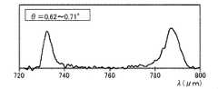
図8A~8Dは、本実施形態の光源装置10における角度周期依存性の理論計算を示すグラフである。図9A~9Dは、角度周期依存性の実験結果を示すグラフである。8A to 8D are graphs showing the theoretical calculation of the angle period dependence in the
図8A~8Dでは、図6A~6Dと同じ励起波長λpにおいて、種々の角度θにおける特性曲線C1を数値計算した。分極周期Λは、Λ=0.639μmに設定した。In FIGS. 8A to 8D, the characteristic curves C1 at various angles θ were numerically calculated at the same excitation wavelength λp as in FIGS. 6A to 6D. The polarization period Λ was set to Λ = 0.639 μm.
図8Aは、角度θ=0.80°の状態を例示する。同様に、図8B,8C,8Dは、それぞれ角度θ=0.71°,0.62°,0.53°の状態を例示する。図8Dの状態と、図6Dの状態とは同様である。図9A,9B,9C,9Dは、それぞれ図8A,8B,8C,8Dに対応する実験結果の波長スペクトルを示す。FIG. 8A illustrates a state where the angle θ = 0.80 °. Similarly, FIGS. 8B, 8C, and 8D exemplify the states at angles θ = 0.71 °, 0.62 °, and 0.53 °, respectively. The state of FIG. 8D and the state of FIG. 6D are the same. 9A, 9B, 9C and 9D show the wavelength spectra of the experimental results corresponding to FIGS. 8A, 8B, 8C and 8D, respectively.
図9A~9Dでは、図7A~7Dと同様の環境において、図8A~8Dの数値計算を確認するための実験を行った。図9A~9Dでは、それぞれ図8A~8Dに対応する角度θから角度範囲0.9°分の光を波長スペクトルの計測対象とした。本実験によると、図9D,9C,9B,9Aに示すように、角度θを大きくするにつれて、2つの蛍光ピークが近づくことが確認できた。In FIGS. 9A-9D, an experiment was conducted to confirm the numerical calculation of FIGS. 8A-8D in the same environment as in FIGS. 7A-7D. In FIGS. 9A to 9D, light for an angle range of 0.9 ° from the angle θ corresponding to FIGS. 8A to 8D was measured for the wavelength spectrum. According to this experiment, as shown in FIGS. 9D, 9C, 9B, and 9A, it was confirmed that the two fluorescence peaks approached as the angle θ was increased.
以上のように、近赤外領域において第1及び第2の光子対G1,G2の波長λn1,λn2の分極周期依存性及び角度依存性が確認できた。又、このことから、それぞれ中赤外領域において対応する波長λm1,λm2の光も同時に得られることが理論的に分かる。更に、各々の場合においてコヒーレント長Lを理論計算すると、数cmを超える程度であった。このことから、コヒーレント長L以下のサイズL12のPP結晶素子12も実用上、容易に得られる。As described above, the polarization period dependence and angle dependence of the wavelengths λn1 and λn2 of the first and second photon pairs G1 and G2 were confirmed in the near infrared region. From this, it can be theoretically understood that light having the corresponding wavelengths λm1 and λm2 can be obtained at the same time in the mid-infrared region, respectively. Further, the theoretical calculation of the coherent length L in each case was about several cm or more. From this, a
また、式(13)に示すように、PP結晶素子12の屈折率n(λ,T)は温度Tに依存することから、特性曲線C1の温度依存性も理論的に把握できる。このことから、光源装置10においてPP結晶素子12の温度Tを適切に設定する、例えば摂氏0度から摂氏300度の間に設定することにより、2種類の光子対G1,G2を生成し易くすることも可能である。Further, as shown in the equation (13), since the refractive index n (λ, T) of the
3.まとめ
以上のように、本実施形態に係る光源装置10は、励起波長λpを有する励起光Lpを生成する光源の一例であるレーザ光源11と、擬似位相整合素子の一例であるPP結晶素子12とを備える。PP結晶素子12は、レーザ光源11から励起光Lpが入射するように配置され、周期的に分極が反転する分極周期Λを有する結晶で構成される。PP結晶素子12において規定される擬似位相整合条件が、励起光Lpの光軸に沿った分極周期Λ及び励起波長λpに基づき、励起光Lpの入射に応じてPP結晶素子12から出射する第1の光子対G1により充足され、且つ第1の光子対G1と共通の分極周期Λ及び励起波長λpに基づき、第1の光子対G1と共通の方向に出射する第2の光子対G2により充足される。第1の光子対G1は、第1の波長帯(例えば近赤外領域)の範囲内の波長λn1(第1波長)と、第1の波長帯とは異なる第2の波長帯(例えば中赤外領域)の範囲内のλm1(第2波長)とを有する。第2の光子対G2は、第1の波長帯の範囲内で波長λn1とは異なる波長λn2(第3波長)と、第2の波長帯の範囲内で波長λm1とは異なるλm2(第4波長)とを有する。3. 3. Summary As described above, the
以上の光源装置10によると、種々の波長λn1~λm2を有する第1及び第2の光子対G1,G2が、擬似位相整合条件を充足するような励起波長λp及び分極周期Λを有するレーザ光源11及びPP結晶素子12という簡単な装置構成において、複数の波長を有する光子対を生成することができる。According to the above
本実施形態の光源装置10において、第1の波長帯は、境界波長λaなどの上限値を有してもよく、第2の波長帯は、第1の波長帯の上限値以上において設定されてもよい(図2参照)。第2の光子対G2による第3波長λn2は、第1の波長帯の範囲内で第1の光子対G1による第1波長λn1よりも長い。第2の光子対G2による第4波長λm2は、第2の波長帯の範囲内で第1の光子対G1による第2波長λn2よりも短い。こうした第2の光子対G2が、第1の光子対G1とは別途存在することにより、量子もつれ2光子状態を実現することができる。In the
本実施形態の光源装置10において、第1の波長帯は、例えば近赤外領域であり、例えば波長700~900nmである。第2の波長帯は、例えば中赤外領域であり、例えば波長2~5μmである。各波長帯の光子Gn1~Gm2を有する第1及第2の光子対G1,G2によると、近赤外領域の光子Gn1,Gn2と中赤外領域の光子Gm1,Gm2とは、光学的に容易に分離可能であることから、量子情報のためのシステムを容易に構築できる。例えば、計測が容易な近赤外領域の光子Gn1,Gn2の波長を観測することにより、対応する中赤外領域の光子Gm1,Gm2を簡単に検知することができる。In the
本実施形態の光源装置10においては、例えば、励起光Lpの光軸を基準として5°以内などの所定の角度範囲内で、励起光Lpの入射に応じてPP結晶素子12から出射する光は、第1及び第2の光子対G1,G2が光軸に沿って出射した場合における、第1波長λn1から第3波長λn2までと、第2波長λm1から第4波長λm2までとを含む帯域を有する(図5参照)。PP結晶素子12から出射する光の帯域は、波長2μmから5μmまでという、中赤外領域における広帯域を含み得る。In the
本実施形態の光源装置10において、第1の光子対G1は、互いに同じ偏光方向を有する2つの光子Gn1,Gm1を含んでもよい。第2の光子対G2は、第1の光子対G1と同じ偏光方向を有する2つの光子Gn2,Gm2を含んでもよい。第1及び第2の光子対G1,G2の偏光方向と、励起光Lpの偏光方向とが同じであってもよい。こうしたtype-0の位相整合において、量子もつれ2光子状態を実現できる。例えば、量子情報のためのシステムにおいて、偏光方向に基づき量子もつれ2光子状態のフィルタを容易に設けられる。In the
本実施形態の光源装置10において、擬似位相整合条件が第1及び第2の光子対G1,G2によって充足されるように、励起波長λp、分極周期Λ、励起光Lpの光軸の向き、及びPP結晶素子12の温度のうちの少なくとも一つが設定されてもよい。例えば、励起光Lpの光軸の向きを変えることにより、励起光Lpの光軸に沿った分極周期Λの大きさが変わる。このことから、実質的にPP結晶素子12の分極周期Λを変更した場合と同様の調整を行うことも可能である。In the
本実施形態の光源装置10において、擬似位相整合条件は、上述した式(1)によって表される。ここで、ωpは励起波長λpに対応する角周波数であり、ωnは第1波長又は第3波長に対応する角周波数であり、ωmは第2波長又は第4波長に対応する角周波数であり、kpは角周波数ωpを有する光子の波数ベクトルであり、knは角周波数ωnを有する光子の波数ベクトルであり、kmは角周波数ωnを有する光子の波数ベクトルであり、Λは分極周期Λであり、eは結晶における向きを示す基準ベクトルであり、Δkはミスマッチを示すベクトルである。In the
本実施形態の光源装置10において、PP結晶素子12に用いる結晶は、LiTaO3結晶である。この場合、励起波長λpは、0.6μm以上0.85μm以下の範囲内に設定可能である。In the
(実施形態2)
実施形態1では、光源装置10の理論計算及び実験結果の一例を説明した。実施形態2では、更なる光源装置10の理論計算及び実験結果の例について説明する。以下、実施形態1とは同様の説明を適宜省略して、実施形態2を説明する。(Embodiment 2)
In the first embodiment, an example of the theoretical calculation and the experimental result of the
図10は、実施形態2の光源装置10における分極周期依存性の理論計算を示すグラフである。図11は、本実施形態の光源装置10における角度依存性の理論計算を示すグラフである。FIG. 10 is a graph showing the theoretical calculation of the polarization period dependence in the
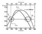
図10,11では、励起光Lpを励起波長λp=0.638μmに設定して、実施形態1と同様にPPSLTの擬似位相整合条件の理論計算を行った。図10の縦軸は分極周期Λ(μm)であり、図11の横軸は出射する光の角度θ(°)である。図10,11における横軸について、各図中の上側に中赤外領域の波長λm(μm)を示し、下側に近赤外領域の波長λn(nm)を示す。以下では、各光子対G1,G2において中赤外光に対応する光子をアイドラ光子といい、近赤外光に対応する光子をシグナル光子という場合がある。In FIGS. 10 and 11, the excitation light Lp was set to the excitation wavelength λp = 0.638 μm, and the theoretical calculation of the pseudo-phase matching condition of PPSLT was performed in the same manner as in the first embodiment. The vertical axis of FIG. 10 is the polarization period Λ (μm), and the horizontal axis of FIG. 11 is the angle θ (°) of the emitted light. Regarding the horizontal axis in FIGS. 10 and 11, the wavelength λm (μm) in the mid-infrared region is shown on the upper side of each figure, and the wavelength λn (nm) in the near-infrared region is shown on the lower side. In the following, the photon corresponding to the mid-infrared light in each photon pair G1 and G2 may be referred to as an idler photon, and the photon corresponding to the near-infrared light may be referred to as a signal photon.
図10では、図2~4と同様の特性曲線C1において、アイドラ光子に対応する中赤外領域近傍の部分C1mと、シグナル光子に対応する近赤外領域近傍の部分C1nとを重ねて図示している。同様に、図11では、図5と同様の放射特性曲線C2において、アイドラ光子に対応する部分C2mと、シグナル光子に対応する部分C2nとを重ねて図示している。In FIG. 10, in the characteristic curve C1 similar to FIGS. 2 to 4, the portion C1m in the vicinity of the mid-infrared region corresponding to the idler photon and the portion C1n in the vicinity of the near-infrared region corresponding to the signal photon are superimposed and shown. ing. Similarly, in FIG. 11, in the radiation characteristic curve C2 similar to that in FIG. 5, the portion C2m corresponding to the idler photon and the portion C2n corresponding to the signal photon are superimposed and shown.
上記の励起波長λpにおいては、図10に示すように、分極周期Λ=16.88μmにおいて、量子もつれ2光子状態のアイドラ光子に対応する波長λm1=5.6μm及び波長λm2=3.5μmが、同時に擬似位相整合条件を満たす。また、図10に示すように、波長λm=3.5~5.6μmの中赤外光が出射する角度が4°の範囲内に収まっている。At the above excitation wavelength λp, as shown in FIG. 10, at the polarization period Λ = 16.88 μm, the wavelength λm1 = 5.6 μm and the wavelength λm2 = 3.5 μm corresponding to the idler photon in the entangled two-photon state are set. At the same time, the pseudo phase matching condition is satisfied. Further, as shown in FIG. 10, the angle at which the mid-infrared light having a wavelength of λm = 3.5 to 5.6 μm is emitted is within the range of 4 °.
図12は、本実施形態の光源装置10における励起波長λpの最適化を説明した図である。図12の縦軸は励起波長λpを示し、横軸はアイドラ光子の波長λmを示す。図12では、上述した量子もつれ2光子状態の擬似位相整合条件について、様々な励起波長λpにおいて求解し、解が得られた領域R1を図示している。領域R1の求解においては、各励起波長λpについて、分極周期Λ及び開口数NAといったパラメータについては可変とした。FIG. 12 is a diagram illustrating optimization of the excitation wavelength λp in the
図12中の破線は、励起波長λp=0.638μm、分極周期Λ=16.88μm、開口数NA=0.07の場合に量子もつれ2光子状態の解が得られた範囲を例示している。図12の領域R1によると、例えば励起波長λp=0.78μmにおいて、λn=2~5μmを含む広帯域の赤外光が得られている。以上のような理論計算の結果を確認するべく、本実施形態では、光源装置10についての実験を行った。The broken line in FIG. 12 illustrates the range in which the solution of the quantum entangled two-photon state is obtained when the excitation wavelength λp = 0.638 μm, the polarization period Λ = 16.88 μm, and the numerical aperture NA = 0.07. .. According to the region R1 of FIG. 12, for example, at an excitation wavelength λp = 0.78 μm, a wide band infrared light including λn = 2 to 5 μm is obtained. In order to confirm the result of the theoretical calculation as described above, in this embodiment, an experiment was conducted on the
図13は、本実施形態における実験的な光源装置10の構成例を示す。本例において、光源装置10は、レーザ光源11及びPP結晶素子12に加えて、レーザ光源11とPP結晶素子12間に配置されるレンズ13と、PP結晶素子12の出射側(+Z側)に順番に並ぶ絞り14、レンズ15、波長フィルタ16およびレンズ17を備える。本構成例の光源装置10は、例えば光ファイバなどの伝送光学系を介してシリコンCCD20に接続される。FIG. 13 shows a configuration example of the experimental
本構成例のレーザ光源11は、CW型で励起波長λp=638nmを有し、平均パワー50mWを有する。レンズ13は、例えば焦点距離100mmを有し、レーザ光源11からの励起光LpをPP結晶素子12に導光する。絞り14は、予め設定される各種の開口数において、PP結晶素子12から出射する光を規制する。レンズ15は、例えば焦点距離200mmを有し、絞り14を通過した光のうちの透過可能な光を導光して、例えば中赤外光を遮断する。波長フィルタ16は、例えば波長700nmよりも大きい波長の光を選択的に通過させ、例えば励起光Lp等を遮断する。レンズ17は、例えば焦点距離50mmを有し、波長フィルタ16を通過した光(例えば近赤外光)を、伝送光学系の一端等に集光する。The
シリコンCCD20は、伝送光学系の他端に接続され、PP結晶素子12において生成されたアイドラ光子およびシグナル光子の光子対のうちのシグナル光子を観測することができる。本実施形態の光源装置10において、シグナル光子の波長帯は、シリコンCCD20等のシリコン製の検出器で検出可能な波長帯にて適宜、設定されてもよく、可視光領域を含んでもよい。この場合のアイドラ光子の波長帯は、例えば赤外領域においてシグナル光子の波長帯と対応するように設定される。The
図14は、本実施形態の光源装置10におけるPP結晶素子12の構成例を示す。本構成例のPP結晶素子12は、ファンアウト型のPPSLTで構成され、例えばZ方向におけるサイズ11mm及びX方向におけるサイズ5mmを有する。PP結晶素子12は、図中の上側(+X側)では比較的短い分極周期Λ1を有し、下側(-X側)では比較的長い分極周期Λ2を有する(例えばΛ1=16.6μm、Λ2=18.3μm)。こうしたPP結晶素子12によると、X方向に沿ってスライドさせることにより、励起光Lpが入射する位置を変更して、利用する分極周期Λの大きさを可変にすることができる。FIG. 14 shows a configuration example of the
以上のように構成される光源装置10を用いて行った実験について、図15~18を用いて説明する。The experiments performed using the
図15は、実施形態2の光源装置10における分極周期依存性の実験結果を示すグラフS11~S17である。図15の実験では、図7A~7Dの実験と同様に、同軸上の過程について分極周期Λを変えながらシグナル光子に対応する近赤外領域における波長λnのスペクトルを計測した。FIG. 15 is graphs S11 to S17 showing the experimental results of the polarization cycle dependence in the
図15において、グラフS11は分極周期ΛをΛ=17.26μmに設定した場合におけるシグナル光子の波長スペクトルである。同様に、グラフS12はΛ=17.18μmであり、グラフS13はΛ=17.09μmであり、グラフS14はΛ=17.00μmであり、グラフS15はΛ=16.92μmであり、グラフS16はΛ=16.83μmであり、グラフS17はΛ=16.75μmであった。In FIG. 15, graph S11 is a wavelength spectrum of signal photons when the polarization period Λ is set to Λ = 17.26 μm. Similarly, graph S12 has Λ = 17.18 μm, graph S13 has Λ = 17.09 μm, graph S14 has Λ = 17.00 μm, graph S15 has Λ = 16.92 μm, and graph S16 has Λ = 16.83 μm, and graph S17 was Λ = 16.75 μm.
図16は、本実施形態における分極周期依存性の理論計算と実験結果との対応関係を示すグラフである。本実施形態において、同軸上の過程(Collinear process)についての分極周期依存性の理論計算(Theoretical calculation)は、図15の実験結果として得られる実験データ(Experimental data)と、図16に示すように良く整合していることが確認された。FIG. 16 is a graph showing the correspondence between the theoretical calculation of the polarization cycle dependence and the experimental results in the present embodiment. In the present embodiment, the theoretical calculation of the polarization period dependence for the coaxial process is as shown in the experimental data (Experimental data) obtained as the experimental result of FIG. 15 and FIG. It was confirmed that they were well aligned.
図17は、実施形態2の光源装置10における角度依存性の実験結果を示すグラフS20~S25である。図17の実験では、開口数NA=0.07として、図9A~9Dの実験と同様に、出射する角度範囲毎に近赤外領域における波長λnのスペクトルを計測した。FIG. 17 is graphs S20 to S25 showing the experimental results of the angle dependence in the
図15において、グラフS20は角度範囲をθ≧0.66°に設定した場合におけるシグナル光子の波長スペクトルである。同様に、グラフS21はθ=0.54~0.66°であり、グラフS22はθ=0.42~0.54°であり、グラフS23はθ=0.30~0.42°であり、グラフS24はθ=0.00~0.30°であった。又、全ての角度範囲を含めた結果をグラフS25に示す。In FIG. 15, graph S20 is a wavelength spectrum of signal photons when the angle range is set to θ ≧ 0.66 °. Similarly, graph S21 has θ = 0.54 to 0.66 °, graph S22 has θ = 0.42 to 0.54 °, and graph S23 has θ = 0.30 to 0.42 °. , Graph S24 was θ = 0.00 to 0.30 °. Further, the result including the entire angle range is shown in the graph S25.
図18は、本実施形態における角度依存性の理論計算と実験結果との対応関係を示すグラフである。本実施形態において、角度依存性の理論計算(Theoretical calculation)も、図17の実験結果として得られる実験データ(Experimental data)と、図18に示すように良く整合していることが確認された。FIG. 18 is a graph showing the correspondence between the theoretical calculation of the angle dependence and the experimental result in the present embodiment. In the present embodiment, it was confirmed that the theoretical calculation of the angle dependence is also well matched with the experimental data obtained as the experimental result of FIG. 17 as shown in FIG.
(他の実施形態)
上記の実施形態1,2においては、擬似位相整合素子の一例としてLiTaO3結晶を用いたPP結晶素子12を例示したが、本開示は特にこれに限定されない。本実施形態において、擬似位相整合素子は、周期分極構造を設けられる各種結晶で構成可能であり、例えばニオブ酸リチウム(LiNbO3)結晶を用いて構成されてもよい。LiNbO3結晶(PPLN)を用いた場合、励起波長λpは、0.65μm以上0.95μm以下に設定可能である。また、本実施形態の擬似位相整合素子は、ニオブ酸カリウム(KNbO3)、またはチタン酸リン酸カリウム(KTiOPO4)等の結晶で構成されてもよい。こうした変形例の一例を、図19,20を用いて説明する。(Other embodiments)
In the above-described first and second embodiments, the PP crystal element 12 using the LiTaO 3 crystal has been illustrated as an example of the pseudo-phase matching element, but the present disclosure is not particularly limited thereto. In the present embodiment, the pseudo-phase matching element can be composed of various crystals provided with a periodic polarization structure, and may be composed of, for example, a lithium niobate (LiNbO3 ) crystal. When a LiNbO3 crystal (PPLN) is used, the excitation wavelength λp can be set to 0.65 μm or more and 0.95 μm or less. Further, the pseudo-phase matching element of the present embodiment may be composed of crystals such aspotassium niobate (KNbO 3 ) or potassium titanate (KTIOPO4). An example of such a modification will be described with reference to FIGS. 19 and 20.
図19は、上記のような光源装置の変形例における分極周期依存性の理論計算を示す。図20は、本変形例の光源装置における角度依存性の理論計算を示す。本変形例の光源装置は、実施形態1,2の光源装置10と同様の構成において、PPSLTの擬似位相整合素子の代わりに、PPLNの擬似位相整合素子を備える。FIG. 19 shows the theoretical calculation of the polarization period dependence in the modified example of the light source device as described above. FIG. 20 shows the theoretical calculation of the angle dependence in the light source device of this modification. The light source device of this modification has a configuration similar to that of the
図19では、図2等の特性曲線C1と同様に、PPLNにおいて擬似位相整合条件を満たす場合における特性曲線C3(PPLN QPM curve)を例示する。図20では、上記の場合における、図5の放射特性曲線C2と同様の放射特性曲線C4においてアイドラ光子に対応する部分を例示する。この際の励起光Lpは、励起波長λp=0.8μmに設定した。又、図20の理論計算では、分極周期Λ=21μmを用いた。FIG. 19 illustrates a characteristic curve C3 (PPLN QPM curve) when the pseudo-phase matching condition is satisfied in PPLN, similarly to the characteristic curve C1 in FIG. FIG. 20 illustrates a portion corresponding to an idler photon in the radiation characteristic curve C4 similar to the radiation characteristic curve C2 in FIG. 5 in the above case. The excitation light Lp at this time was set to an excitation wavelength λp = 0.8 μm. Further, in the theoretical calculation of FIG. 20, the polarization period Λ = 21 μm was used.
図19に示すように、PPLNの擬似位相整合素子においても、別々の波長帯において2つのピークを有する特性曲線C3が得られ、実施形態1,2と同様に量子もつれ2光子状態を実現できることが確認された。また、PPLNの擬似位相整合素子においては、図20に示すように、励起波長λp=0.8μmに基づき、中赤外領域の波長λm=2~5μmにわたる広帯域の赤外光が、開口数NA=0.1程度で得られることが確認できた。As shown in FIG. 19, even in the pseudo-phase matching element of PPLN, the characteristic curve C3 having two peaks in different wavelength bands can be obtained, and the quantum entangled two-photon state can be realized as in the first and second embodiments. confirmed. Further, in the PPLN pseudo-phase matching element, as shown in FIG. 20, a wide band infrared light having a wavelength λm = 2 to 5 μm in the mid-infrared region is emitted with a numerical aperture NA based on the excitation wavelength λp = 0.8 μm. It was confirmed that it can be obtained at about 0.1.
また、実施形態1では、擬似位相整合素子の一例として分極周期Λが一定のPP結晶素子12を例示した。本実施形態において、擬似位相整合素子の分極周期Λは、擬似位相整合素子の内部で変化してもよい。例えば、同軸方向に沿って分極周期Λが変化するチャープ型の周期分極構造により、擬似位相整合素子が構成されてもよい。この場合、分極周期Λの変化に応じて、同軸方向に出射する光の帯域を広帯域にすることができる。また、本実施形態において、擬似位相整合素子の周期分極構造は、種々の構成であってもよく、例えばチャープ型に限らず、ファンアウト型、シングルグレーティング型、マルチグレーティング型、或いはハイブリッド型等であってもよい。Further, in the first embodiment, the
また、上記の各実施形態では、光源装置10における光源の一例としてレーザ光源11を例示した。本実施形態において、光源装置10における光源は、レーザ光源と各種の波長変換素子との組み合わせで構成されてもよい。こうした波長変換素子は、例えばPP結晶素子12と一体的に構成されてもよい。また、本実施形態において光源装置10における光源は必ずしもレーザ光源をに限らず、種々の固体光源を含んでもよい。また、光源装置10における励起波長λpは、特に可視領域に限らず、適宜設計に応じて種々の波長帯にて設定可能である。Further, in each of the above embodiments, the
また、上記の各実施形態では、type-0の位相整合による量子もつれ2光子状態を説明した。本実施形態はtype-0に限らず、例えばtype-II又はtype-Iの位相整合も利用可能である。この場合においても、各々の偏光方向における屈折率等を用いて実施形態1と同様の理論計算が適用でき、光源装置10の各種パラメータを適宜設計可能である。Further, in each of the above embodiments, the quantum entangled two-photon state due to the phase matching of type-0 has been described. The present embodiment is not limited to type-0, and for example, phase matching of type-II or type-I can also be used. Also in this case, the same theoretical calculation as in the first embodiment can be applied by using the refractive index and the like in each polarization direction, and various parameters of the
本開示は、例えば量子情報技術に適用可能であるが、これに限定されるものではない。例えば、本開示は、赤外線を利用した分光/分析といった様々な分野にも適用可能である。The present disclosure is applicable to, for example, quantum information technology, but is not limited thereto. For example, the present disclosure is also applicable to various fields such as spectroscopy / analysis using infrared rays.
Claims (10)
Translated fromJapanese前記光源から前記励起光が入射するように配置され、周期的に分極が反転する分極周期を有する結晶で構成される擬似位相整合素子とを備え、
前記擬似位相整合素子において規定される擬似位相整合条件が、
前記励起光の光軸に沿った分極周期及び励起波長に基づき、前記励起光の入射に応じて前記擬似位相整合素子から出射する第1の光子対により充足され、且つ
前記第1の光子対と共通の分極周期及び励起波長に基づき、前記第1の光子対と共通の方向に出射する第2の光子対により充足され、
前記第1の光子対は、第1の波長帯の範囲内の第1波長と、前記第1の波長帯とは異なる第2の波長帯の範囲内の第2波長とを有し、
前記第2の光子対は、前記第1の波長帯の範囲内で前記第1波長とは異なる第3波長と、前記第2の波長帯の範囲内で前記第2波長とは異なる第4波長とを有する
光源装置。A light source that produces excitation light with an excitation wavelength,
It is provided with a pseudo-phase matching element composed of crystals arranged so that the excitation light is incident from the light source and having a polarization period in which the polarization is periodically reversed.
The pseudo-phase matching condition defined in the pseudo-phase matching element is
Based on the polarization period and excitation wavelength along the optical axis of the excitation light, it is filled with the first photon pair emitted from the pseudo-phase matching element in response to the incident of the excitation light, and is filled with the first photon pair. Based on a common polarization period and excitation wavelength, it is filled with a second photon pair that emits in the same direction as the first photon pair.
The first photon pair has a first wavelength within the range of the first wavelength band and a second wavelength within the range of the second wavelength band different from the first wavelength band.
The second photon pair has a third wavelength different from the first wavelength within the range of the first wavelength band and a fourth wavelength different from the second wavelength within the range of the second wavelength band. Light source device having and.
前記第2の波長帯は、前記第1の波長帯の上限値以上において設定され、
前記第3波長は、前記第1の波長帯の範囲内で前記第1波長よりも長く、
前記第4波長は、前記第2の波長帯の範囲内で前記第2波長よりも短い
請求項1に記載の光源装置。The first wavelength band has an upper limit value and has an upper limit value.
The second wavelength band is set above the upper limit of the first wavelength band, and is set.
The third wavelength is longer than the first wavelength within the range of the first wavelength band.
The light source device according to claim 1, wherein the fourth wavelength is shorter than the second wavelength within the range of the second wavelength band.
請求項2に記載の光源装置。The light source device according to claim 2, wherein the first wavelength band is a near-infrared region, and the second wavelength band is a mid-infrared region.
前記第1及び第2の光子対が前記光軸に沿って出射した場合における、前記第1波長から前記第3波長までと、前記第2波長から前記第4波長までとを含む帯域を有する
請求項1~3のいずれか1項に記載の光源装置。Within a predetermined angle range with respect to the optical axis, the light emitted from the pseudo-phase matching element in response to the incident of the excitation light is
A claim having a band including the first wavelength to the third wavelength and the second wavelength to the fourth wavelength when the first and second photon pairs are emitted along the optical axis. Item 3. The light source device according to any one of Items 1 to 3.
請求項4に記載の光源装置。The light source device according to claim 4, wherein the band of light emitted from the pseudo-phase matching element includes a wavelength of 2 μm to 5 μm.
前記第2の光子対は、前記第1の光子対と同じ偏光方向を有する2つの光子を含み、
前記第1及び第2の光子対の偏光方向と、前記励起光の偏光方向とが同じである
請求項1~5のいずれか1項に記載の光源装置。The first photon pair contains two photons having the same polarization direction as each other.
The second photon pair contains two photons having the same polarization direction as the first photon pair.
The light source device according to any one of claims 1 to 5, wherein the polarization directions of the first and second photon pairs are the same as the polarization directions of the excitation light.
請求項1~6のいずれか1項に記載の光源装置。At least one of the excitation wavelength, the polarization period, the orientation of the optical axis, and the temperature of the pseudo-phase matching element so that the pseudo-phase matching conditions are satisfied by the first and second photon pairs. The light source device according to any one of claims 1 to 6, which is set.

請求項1~7のいずれか1項に記載の光源装置。The pseudo-phase matching condition is expressed by the following equation.
請求項1~8のいずれか1項に記載の光源装置。The light source device according to any one of claims 1 to 8, wherein the crystal is a lithium tantalate crystal or a lithium niobate crystal.
請求項1~9のいずれか1項に記載の光源装置。The light source device according to any one of claims 1 to 9, wherein the excitation wavelength is 0.6 μm or more and 0.95 μm or less.
Applications Claiming Priority (2)
| Application Number | Priority Date | Filing Date | Title |
|---|---|---|---|
| JP2020-031981 | 2020-02-27 | ||
| JP2020031981AJP2023040319A (en) | 2020-02-27 | 2020-02-27 | Light source device |
Publications (1)
| Publication Number | Publication Date |
|---|---|
| WO2021172361A1true WO2021172361A1 (en) | 2021-09-02 |
Family
ID=77490002
Family Applications (1)
| Application Number | Title | Priority Date | Filing Date |
|---|---|---|---|
| PCT/JP2021/006877CeasedWO2021172361A1 (en) | 2020-02-27 | 2021-02-24 | Light source device |
Country Status (2)
| Country | Link |
|---|---|
| JP (1) | JP2023040319A (en) |
| WO (1) | WO2021172361A1 (en) |
Cited By (1)
| Publication number | Priority date | Publication date | Assignee | Title |
|---|---|---|---|---|
| CN115469497A (en)* | 2022-09-14 | 2022-12-13 | 济南量子技术研究院 | Quantum entanglement source of double-path periodic polarization waveguide |
Citations (3)
| Publication number | Priority date | Publication date | Assignee | Title |
|---|---|---|---|---|
| US5640405A (en)* | 1996-02-01 | 1997-06-17 | Lighthouse Electronics Corporation | Multi quasi phase matched interactions in a non-linear crystal |
| WO2009093391A1 (en)* | 2008-01-25 | 2009-07-30 | Japan Science And Technology Agency | Non-degenerate polarization-entangled photon pairs generation device and non-degenerate polarization-entangled photon pairs generation method |
| JP2013526726A (en)* | 2010-05-18 | 2013-06-24 | コーニング インコーポレイテッド | Multi-wavelength optical system |
- 2020
- 2020-02-27JPJP2020031981Apatent/JP2023040319A/enactivePending
- 2021
- 2021-02-24WOPCT/JP2021/006877patent/WO2021172361A1/ennot_activeCeased
Patent Citations (3)
| Publication number | Priority date | Publication date | Assignee | Title |
|---|---|---|---|---|
| US5640405A (en)* | 1996-02-01 | 1997-06-17 | Lighthouse Electronics Corporation | Multi quasi phase matched interactions in a non-linear crystal |
| WO2009093391A1 (en)* | 2008-01-25 | 2009-07-30 | Japan Science And Technology Agency | Non-degenerate polarization-entangled photon pairs generation device and non-degenerate polarization-entangled photon pairs generation method |
| JP2013526726A (en)* | 2010-05-18 | 2013-06-24 | コーニング インコーポレイテッド | Multi-wavelength optical system |
Non-Patent Citations (4)
| Title |
|---|
| CHAITANYA KUMAR, ESTEBAN-MARTIN ADOLFO, IDEGUCHI TAKURO, YAN MING, HOLZNER SIMON, HÄNSCH THEODOR W., PICQUÉ NATHALIE, EBRAHIM-ZAD: "Few-cycle, broadband, mid- infrared optical parametric oscillator pumped by a 20-fs Ti:sapphire laser", LASER & PHOTONICS REVIEWS, vol. 8, no. 5, 1 September 2014 (2014-09-01), DE, pages 86 - 91, XP055633393, ISSN: 1863-8880* |
| HUO MEIRU; QIN JILIANG; YAN ZHIHUI; JIA XIAOJUN; PENG KUNCHI: "Generation of two types of nonclassical optical states using an optical parametric oscillator with a PPKTP crystal", APPLIED PHYSICS LETTERS, vol. 109, 221101, 28 November 2016 (2016-11-28), US, pages 1 - 5, XP012213965, ISSN: 0003-6951, DOI: 10.1063/1.4968801* |
| JI, F. ; LU, R. ; LI, B. ; ZHANG, B. ; YAO, J.: "Mid-infrared tunable dual- wavelength generation based on a quasi-phase- matched optical parametric oscillator", OPTICS COMMUNICATIONS, vol. 282, 1 January 2009 (2009-01-01), pages 126 - 128, XP025678506, ISSN: 0030-4018* |
| LIN, H. ; TAN, H. ; MIAO, J. ; CUI, T. ; SU, S. ; GUO, J.: "Extra-cavity, widely tunable, continuous wave MgO-doped PPLN optical parametric oscillator pumped with a Nd:YV04 laser", OPTICAL MATERIALS, vol. 32, no. 1, 1 November 2009 (2009-11-01), NL, pages 257 - 260, XP026698747, ISSN: 0925-3467, DOI: 10.1016/j.optmat.2009.07.019* |
Cited By (1)
| Publication number | Priority date | Publication date | Assignee | Title |
|---|---|---|---|---|
| CN115469497A (en)* | 2022-09-14 | 2022-12-13 | 济南量子技术研究院 | Quantum entanglement source of double-path periodic polarization waveguide |
Also Published As
| Publication number | Publication date |
|---|---|
| JP2023040319A (en) | 2023-03-23 |
Similar Documents
| Publication | Publication Date | Title |
|---|---|---|
| US7339718B1 (en) | Generation of terahertz radiation in orientation-patterned semiconductors | |
| JP6810954B2 (en) | Terahertz wave generator, optical parametric amplifier, terahertz wave detector, and non-linear optics | |
| US7489436B1 (en) | Hybrid integrated source of polarization-entangled photons | |
| JP5240864B2 (en) | Non-degenerate polarization entangled photon pair generator and non-degenerate polarization entangled photon pair generation method | |
| US11448938B2 (en) | Entangled photon source that can replace a pulsed laser in non-ablative multiphoton and nonlinear processes | |
| JP6229923B2 (en) | Terahertz wave detection apparatus and method | |
| Megidish et al. | Compact 2D nonlinear photonic crystal source of beamlike path entangled photons | |
| Li et al. | Three‐Body Topology Entanglement Generation via a Six‐Wave Mixing: Competing and Coexisting of Linear and Nonlinear Optics Responses in Triphoton Temporal Correlation | |
| O’Donnell et al. | Observation of ultrabroadband, beamlike parametric downconversion | |
| Stefanska et al. | Experimental observation of the spontaneous emission of a space–time wavepacket in a multimode optical fiber | |
| EP2626742B1 (en) | Wavelength converting apparatus, light source apparatus and wavelength converting method | |
| WO2021172361A1 (en) | Light source device | |
| Huang et al. | Integrated reconfigurable photon-pair source based on high-Q nonlinear chalcogenide glass microring resonators | |
| Chen et al. | Concurrent optical parametric down-conversion in χ (2) nonlinear photonic crystals | |
| Shi et al. | Steering second-harmonic beams in nanophotonic waveguides by gratings | |
| Sinha et al. | Tunable, room temperature CMOS-compatible THz emitters based on nonlinear mixing in microdisk resonators | |
| Roy et al. | Novel proposal for all-optical Fredkin logic gate with bacteriorhodopsin-coated microcavity and its applications | |
| Signorini et al. | Broad wavelength generation and conversion with multi modal four wave mixing in silicon waveguides | |
| Yadav et al. | Far-infrared frequency mode conversion using bulk acoustic phonon modes | |
| WO2022239058A1 (en) | Wavelength converting device | |
| Bharadwaj et al. | Generation of polarization-entangled photon pairs in a planar waveguide | |
| JP4468842B2 (en) | Electromagnetic wave generating element | |
| Gao et al. | Overcoming Losses through Phase Locking in Nonlinear Quasi-Bound States in the Continuum Metasurfaces | |
| TWI470887B (en) | Laser frequency-doubling module | |
| JP4553822B2 (en) | Wavelength conversion module |
Legal Events
| Date | Code | Title | Description |
|---|---|---|---|
| 121 | Ep: the epo has been informed by wipo that ep was designated in this application | Ref document number:21760985 Country of ref document:EP Kind code of ref document:A1 | |
| NENP | Non-entry into the national phase | Ref country code:DE | |
| 122 | Ep: pct application non-entry in european phase | Ref document number:21760985 Country of ref document:EP Kind code of ref document:A1 | |
| NENP | Non-entry into the national phase | Ref country code:JP |