WO2021172122A1 - Heat dissipation structure and electronic device - Google Patents
Heat dissipation structure and electronic deviceDownload PDFInfo
- Publication number
- WO2021172122A1 WO2021172122A1PCT/JP2021/005800JP2021005800WWO2021172122A1WO 2021172122 A1WO2021172122 A1WO 2021172122A1JP 2021005800 WJP2021005800 WJP 2021005800WWO 2021172122 A1WO2021172122 A1WO 2021172122A1
- Authority
- WO
- WIPO (PCT)
- Prior art keywords
- heat
- conductive member
- heat dissipation
- heat conductive
- dissipation structure
- Prior art date
- Legal status (The legal status is an assumption and is not a legal conclusion. Google has not performed a legal analysis and makes no representation as to the accuracy of the status listed.)
- Ceased
Links
Images


Classifications
- H—ELECTRICITY
- H01—ELECTRIC ELEMENTS
- H01L—SEMICONDUCTOR DEVICES NOT COVERED BY CLASS H10
- H01L23/00—Details of semiconductor or other solid state devices
- H01L23/34—Arrangements for cooling, heating, ventilating or temperature compensation ; Temperature sensing arrangements
- H01L23/40—Mountings or securing means for detachable cooling or heating arrangements ; fixed by friction, plugs or springs
- H—ELECTRICITY
- H01—ELECTRIC ELEMENTS
- H01L—SEMICONDUCTOR DEVICES NOT COVERED BY CLASS H10
- H01L23/00—Details of semiconductor or other solid state devices
- H01L23/34—Arrangements for cooling, heating, ventilating or temperature compensation ; Temperature sensing arrangements
- H01L23/42—Fillings or auxiliary members in containers or encapsulations selected or arranged to facilitate heating or cooling
- H01L23/427—Cooling by change of state, e.g. use of heat pipes
- H—ELECTRICITY
- H05—ELECTRIC TECHNIQUES NOT OTHERWISE PROVIDED FOR
- H05K—PRINTED CIRCUITS; CASINGS OR CONSTRUCTIONAL DETAILS OF ELECTRIC APPARATUS; MANUFACTURE OF ASSEMBLAGES OF ELECTRICAL COMPONENTS
- H05K7/00—Constructional details common to different types of electric apparatus
- H05K7/20—Modifications to facilitate cooling, ventilating, or heating
Definitions
- the present disclosurerelates to a heat radiating structure for radiating or cooling the heat generated by an electronic component and an electronic device provided with the heat radiating structure.
- a heat conductive plateis arranged in a part of a cooling portion for cooling an optical component such as a liquid crystal light valve, and the heat radiation amount is increased by connecting the heat conductive plate and the heat pipe.
- the projector deviceis disclosed.
- the heat dissipation structure of one embodiment of the present disclosureincludes a hollow structure having a heat diode function, and includes a heat conductive member that comes into contact with a heat source portion due to elastic deformation, and a support member that supports the heat conductive member. ..
- the electronic device of the embodiment of the present disclosureincludes an electronic component that generates heat as a heat source portion and a heat radiating structure that dissipates heat generated by the electronic component. Has a heat dissipation structure.
- the heat dissipation structure of one embodiment and the electronic device of one embodiment of the present disclosureinclude a hollow structure having a heat diode function, and by using a heat conductive member that comes into contact with the heat source portion by elastic deformation, the heat conduction with the heat source portion. The contact area with the member is improved.
- FIG. 5is a schematic cross-sectional view of the heat dissipation structure shown in FIG. It is a transmission perspective view explaining the heat dissipation structure and the internal structure of the storage medium shown in FIG. It is a transmission perspective view which shows an example of the structure of the heat dissipation structure which concerns on 2nd Embodiment of this disclosure.
- FIG. 5is a schematic cross-sectional view of the heat dissipation structure shown in FIG. It is a transmission perspective view which shows an example of the structure of the heat dissipation structure which concerns on 3rd Embodiment of this disclosure.
- FIG. 5is a schematic cross-sectional view of the heat dissipation structure shown in FIG. It is a transmission perspective view which shows an example of the structure of the heat dissipation structure which concerns on 3rd Embodiment of this disclosure.
- FIG. 6is a schematic cross-sectional view of the heat dissipation structure shown in FIG. It is a transmission perspective view which shows an example of the structure of the heat dissipation structure which concerns on 4th Embodiment of this disclosure.
- FIG. 5is a schematic cross-sectional view of the heat dissipation structure shown in FIG. It is a transmission perspective view which shows an example of the structure of the heat dissipation structure which concerns on 5th Embodiment of this disclosure.
- FIG. 5is a schematic cross-sectional view of the heat dissipation structure shown in FIG. It is a perspective view which shows an example of the appearance of the heat dissipation structure which concerns on the modification of this disclosure.
- Itis sectional drawing of the heat radiation structure shown in FIG. It is a figure which shows an example of the appearance of the electronic device (camera) as an application example of this disclosure.
- Second embodimentan example of a heat dissipation structure in which a hollow structure and a heat conductive member (leaf spring) having a spring property are fixed to a support substrate. 3.
- Third Embodiment(Another example of a heat dissipation structure in which a heat conductive member (leaf spring) having a hollow structure and a spring property is fixed to a support substrate) 4.
- Fourth embodiment(an example of a heat dissipation structure using a disc spring as a heat conductive member) 5.
- Fifth Embodimentanother example of a heat dissipation structure using a disc spring as a heat conductive member. 6.
- Modification example(example of heat dissipation structure for cooling the battery) 7.
- Application example(example of heat dissipation structure for cooling the battery) 7.
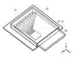
- FIG. 1is a perspective view schematically showing a configuration of a heat radiating structure (heat radiating structure 1) according to the first embodiment of the present disclosure together with an electronic component having a heat generating portion (for example, a storage medium 20).
- FIG. 2schematically shows a cross-sectional structure of the heat radiating structure 1 and the storage medium 20 in the I-I line shown in FIG.
- FIG. 3is a transparent perspective view for explaining the internal structure of the heat dissipation structure 1 and the storage medium 20 shown in FIG.
- This heat dissipation structure 1is used for heat dissipation or cooling of electronic components arranged inside various electronic devices such as a camera 100 (see FIG.
- the heat conductive member 11 for radiating or cooling the heat generated in the storage medium 20has a hollow structure having a thermal diode function and springiness, so that the heat is stored by elastic deformation. It is configured to be in surface contact with, for example, the heat generating portion (heat source) of the medium 20.
- the heat dissipation structure 1has a heat conductive member 11 and a support member 12 that supports the heat conductive member 11.
- the support member 12has, for example, a support substrate 13 and an accommodating member 14, and by combining the support substrate 13 and the accommodating member 14, for example, a slot X into which the storage medium 20 is inserted is formed.
- the heat conductive member 11is for cooling the heat generating portion of the storage medium 20.
- the heat conductive member 11is composed of a hollow structure having a thermal diode function and a member having a spring property.
- the heat conductive member 11can be formed by a heat pipe having a leaf spring shape.
- a heat pipehas a hollow pipe filled with a small amount of a volatile liquid (refrigerant) such as water, and has a capillary structure called a wick on the inner wall of the pipe.
- a volatile liquidsuch as water
- the refrigerantabsorbs heat on the inner wall of the high temperature part and evaporates, and the vapor moves in the space inside the pipe and is cooled in the low temperature part (cooling part).
- the cooled vaporaggregates and returns to a liquid, is absorbed by the wick on the inner wall of the pipe, and is transported to the high temperature part again.
- heatheat is transferred from the high temperature part to the low temperature part by circulating the refrigerant between the high temperature part and the low temperature part in the space inside the pipe as described above.
- the heat conductive member 11includes, for example, a fixing portion 11A fixed to the support member 12, and a heat generating portion of the storage medium 20 which is a heat source and its vicinity (specifically, the storage medium 20), as shown in FIG. 2, for example. It has a contact portion 11B that comes into contact with the case portion) in the vicinity of the heat generating portion of the above.
- the fixing portion 11Acorresponds to the low temperature portion
- the contact portion 11Bcorresponds to the high temperature portion. That is, the refrigerant inside the heat conductive member 11 absorbs the heat generated by the heat generating portion of the storage medium 20 at the contact portion 11B, evaporates, and moves toward the fixed portion 11A as steam.
- the refrigerant (steam) that has moved to the fixed portion 11Ais cooled and returned to a liquid, is absorbed by the wick inside the heat conductive member 11, and moves again to the contact portion 11B due to gravity, capillary force, or the like.
- the heat conductive member 11is separated by cutting a part of the upper surface portion of the accommodating member 14 constituting the support member 12 facing the support substrate 13 into a frame shape, leaving one side, for example. It is formed by processing the upper surface portion.
- the fixing portion 11A of the heat conductive member 11is connected to the frame portion of the accommodating member 14.
- the separated upper surface portionis bent toward the support substrate 13, and constitutes a contact portion 11B with the storage medium 20. Further, the tip of the separated upper surface portion is warped in a direction opposite to, for example, the support substrate 13 side, thereby preventing the heat conductive member 11 from being caught when the storage medium 20 is inserted, for example.
- the heat conductive member 11is preferably formed using a material having high heat conductivity. Specific materials include, for example, beryllium copper, beryllium copper, aluminum and the like. Among the above materials, the heat conductive member 11 is preferably formed using beryllium copper.
- a storage medium 20 that serves as a heat sourceis accommodated while supporting the support member 12 and the heat conductive member 11.
- the support member 12has, for example, a support substrate 13 and an accommodating member 14, and by combining the support substrate 13 and the accommodating member 14, for example, a slot X into which the storage medium 20 is inserted is configured. doing. Inside the slot X, for example, a plurality of terminals 15 that are electrically connected to a plurality of wirings 22 of the storage medium 20 are provided.
- the support substrate 13is, for example, a plate-shaped member that supports the accommodating member 14 and has one surface provided with a plurality of terminals 15, and can be formed by using, for example, glass or epoxy. ..
- the accommodating member 14has an upper surface portion and a side surface portion facing one surface of the support substrate 13, which forms a slot X when combined with the support substrate 13, and can be formed by using, for example, beryllium copper or the like. ..
- a part of the upper surface portion of the accommodating member 14also serves as the heat conductive member 11. Therefore, the accommodating member 14 may be formed by using, for example, beryllium copper, similarly to the heat conductive member 11.
- the accommodating member 14for example, only the portion of the upper surface portion constituting the heat conductive member 11 may be formed by a hollow heat pipe, or the entire accommodating member 14 may be formed by a hollow heat pipe. good.
- a heat radiating member 16may be further provided on the fixing portion 11A of the heat conductive member 11.
- the heat radiating member 16can be formed by using, for example, a plurality of fins.
- the storage medium 20has a heat generating portion inside, and corresponds to a specific example of the "heat source portion" of the present disclosure.
- the storage medium 20is, for example, a memory card, and has an integrated circuit (IC) 21 and wiring 22 connected to the IC 21 inside.
- ICintegrated circuit
- the IC 21generates heat.
- the heat conductive member 11is formed by using a hollow structure having a thermal diode function and a member having a spring property. As a result, the heat conductive member 11 can be brought into surface contact with the heat generating portion (for example, IC21) of the storage medium 20 such as a memory card by elastic deformation. That is, the contact area of the heat conductive member 11 with respect to the heat source portion is improved. This will be described below.
- An example of an electronic component that generates a large amount of heat during operationis a memory card used as a storage medium for a digital camera or the like.
- the memory cardis an electronic component to be inserted and removed, it is thermally connected to peripheral components. Difficult to connect.
- a general heat dissipation methodit is conceivable to bring a high thermal conductor such as a graphite sheet or a heat pipe into contact with the memory card.
- the high thermal conductor as described abovehas high rigidity, the memory card cannot be inserted or removed when it is brought into contact with the conductor.
- the heat conductive member 11by forming the heat conductive member 11 using a member having a hollow structure and a spring property, the heat conductive member 11 is brought into surface contact with the storage medium 20 as a heat source by elastic deformation. bottom. This makes it possible to improve the contact area of the heat conductive member 11 with respect to the storage medium 20 without hindering the insertion and removal of the storage medium 20.
- the heat conductive member 11is formed by using the hollow structure and the member having the spring property, the heat conductive member 11 is elastically deformed with respect to the storage medium 20.
- the surface contactcan be made, and the contact area of the heat conductive member 11 with respect to the storage medium 20 is improved. Therefore, it is possible to improve the cooling efficiency.
- the heat dissipation structure 1 of the present embodimentis particularly effective as a heat dissipation means for electronic components such as the memory card described above, which have a gap between the peripheral components and which are difficult to thermally connect.
- the heat conductive member 11is formed by using a member having a hollow structure and a spring property, the durability of the electronic component to be inserted and removed, such as a memory card, as a heat dissipation structure is improved. It becomes possible to make it.
- the heat conductivityis significantly increased (for example, as compared with the heat radiation structure using a general copper leaf spring). It is possible to improve it to about 25 times). Furthermore, the heat conductive member 11 using beryllium copper can significantly improve the spring strength (for example, about 30 times) as compared with the heat conductive member 11 using, for example, a copper heat pipe.
- FIG. 4is a transmission perspective view schematically showing the configuration of the heat dissipation structure (heat dissipation structure 2) according to the second embodiment of the present disclosure together with an electronic component having a heat generating portion (for example, a storage medium 20).
- FIG. 5schematically shows the cross-sectional structure of the heat dissipation structure 2 and the storage medium 20 in the line II-II shown in FIG.
- the heat dissipation structure 2is used for heat dissipation or cooling of electronic components arranged inside various electronic devices such as a camera 100, which will be described later, as in the first embodiment.
- the heat conductive member 31 for radiating or cooling the heat generated in the storage medium 20 and the support member 41are provided as separate bodies, and the heat conductive member 31 is a support member. It is fixed to the support substrate 42 side constituting 41.
- the heat conductive member 31has the same configuration as the heat conductive member 11 described above, except that the heat conductive member 31 is formed separately from the support member 41 as described above.
- the heat conductive member 31is composed of a hollow structure and a member having a spring property, and can be formed by, for example, a heat pipe having a leaf spring shape.
- the heat conductive member 31has, for example, a fixing portion 31A fixed to, for example, a support substrate 42 constituting the support member 41, and a contact portion 31B in contact with a heat generating portion of the storage medium 20 which is a heat source, and is fixed.
- the portion 31Ais fixed to the inside of the slot X formed by combining with the accommodating member 43 on one surface (upper surface: surface 42S1) of the support substrate 42.
- the fixing portion 31Acan be fixed by using, for example, solder or the like.
- the support member 41has, for example, a support substrate 42 and an accommodating member 43, and by combining the support substrate 42 and the accommodating member 43, for example, a slot X into which the storage medium 20 is inserted is formed.
- a plurality of terminals electrically connected to, for example, a plurality of wirings 22 of the storage medium 20are provided inside the slot X, as in the first embodiment. There is.
- the support substrate 42is, for example, a plate-shaped member that supports the accommodating member 43 and has one surface (surface 42S1) provided with a plurality of terminals, and the surface 42S1 is formed on the surface 42S1 of the heat conductive member 31.
- the fixing portion 31Ais fixed.
- the support substrate 42can be formed by using, for example, ceramics or the like. Among them, for example, the support substrate 42 can be used as a heat radiating member by forming it using an alumina substrate having high thermal conductivity.
- the accommodating member 43has an upper surface portion and a side surface portion facing the surface 42S1 of the support substrate 42, and can be formed by using, for example, stainless steel.
- the heat conductive member 31 and the support member 41are provided as separate members, and the fixing portion 31A of the heat conductive member 31 is provided on the upper surface (surface) of the support substrate 42 constituting the support member 41. It was fixed to 42S1). As described above, even when the heat conductive member 31 and the support member 41 are provided as separate members, the same effect as that of the first embodiment can be obtained.
- FIG. 6is a transmission perspective view schematically showing the configuration of the heat dissipation structure (heat dissipation structure 3) according to the third embodiment of the present disclosure together with an electronic component having a heat generating portion (for example, a storage medium 20). .. FIG. 7 schematically shows the cross-sectional structure of the heat dissipation structure 3 and the storage medium 20 in the lines III-III shown in FIG.
- the heat dissipation structure 3is used for heat dissipation or cooling of electronic components arranged inside various electronic devices such as a camera 100, which will be described later, as in the first embodiment.
- the fixing portion 31A of the heat conductive member 31is fixed to the other surface (lower surface: surface 42S2) side opposite to the surface 42S1 of the support substrate 42 constituting the support member 41.
- the contact portion 31B of the heat conductive member 31is pulled out to the surface 42S1 side of the support substrate 42 through the opening 42H provided in the support substrate 42, which is different from the second embodiment.
- the heat conductive member 31has the same configuration as that of the second embodiment described above.
- the support substrate 42has an opening 42H in which the contact portion 31B of the heat conductive member 31 fixed to the surface 42S2 side of the support substrate 42 can be pulled out to the surface 42S1 side, for example, in the slot X. It is provided at the corresponding position.
- the heat radiating member 44may be provided on the fixing portion 31A of the heat conductive member 31 fixed to the surface 42S2 of the support substrate 42.
- the heat radiating member 44can be formed by using, for example, a plurality of fins, as in the first embodiment.
- the fixing portion 31A of the heat conductive member 31is fixed to the lower surface (surface 42S2) of the support substrate 42 constituting the support member 41, and the opening 42H provided in the support substrate 42 is opened. It was pulled out to the surface 42S1 side of the support substrate 42 through the support substrate 42. Even in such a configuration, the same effect as that of the first embodiment can be obtained.
- the heat radiating member 44can be arranged with respect to the heat conductive member 31. It will be possible. Therefore, it is possible to improve the cooling efficiency as compared with the second embodiment.
- FIG. 7shows an example in which the fixing portion 31A of the heat conductive member 31 is directly fixed to the lower surface (surface 42S2) of the support substrate 42, and the heat radiating member 44 is arranged on the surface opposite to the support substrate 42 side.
- a heat radiating member 44is arranged between the fixing portion 31A of the heat conductive member 31 and the lower surface (surface 42S2) of the support substrate 42, and the fixing portion 31A is placed on the lower surface (surface 42S2) of the support substrate 42 via the heat radiating member 44. May be fixed.
- FIG. 8is a transmission perspective view schematically showing the configuration of the heat dissipation structure (heat dissipation structure 4) according to the fourth embodiment of the present disclosure together with an electronic component having a heat generating portion (for example, a storage medium 20). .. FIG. 9 schematically shows the cross-sectional structure of the heat dissipation structure 4 and the storage medium 20 in the IV-IV line shown in FIG.
- the heat dissipation structure 4is used for heat dissipation or cooling of electronic components arranged inside various electronic devices such as a camera 100, which will be described later, as in the first embodiment.
- the heat dissipation structure 4 of the present embodimentis different from the second embodiment in that the heat conductive member 51 having a disc spring shape is used.
- the heat conductive member 51has the same configuration as the above-mentioned heat conductive member 11 except that it has a disc spring shape.
- the heat conductive member 51is formed of, for example, a heat pipe having a disc spring shape.
- the disc springis, for example, a disc-shaped plate having a hole in the center formed into a conical shape and shaped like a plate without a bottom.
- the heat conductive member 51 of the present embodimenthas, for example, a peripheral portion forming a surface substantially parallel to the surface 42S1 of the support substrate 42, for example, in the lower portion of the cone, and this peripheral portion is the peripheral portion of the support substrate 42. It constitutes a fixing portion 51A fixed to the surface 42S1.
- the heat conductive member 51 fixed to the surface 42S1 of the support substrate 42has a shape in which the upper portion of the cone inside the slot X protrudes in the normal direction with respect to the surface 42S1 of the support substrate 42, for example, in the slot X.
- the upper portion of the conebends so that the storage medium 20 comes into surface contact with the heat generating portion (for example, IC21) of the storage medium 20. That is, the upper portion of the cone constitutes the contact portion 51B.
- the heat conductive member 51 having a disc spring shapeis used. Even in such a configuration, the same effect as that of the first embodiment can be obtained.
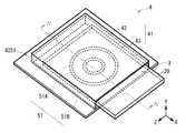
- FIG. 10is a perspective view schematically showing the configuration of the heat radiating structure (heat radiating structure 5) according to the fifth embodiment of the present disclosure together with an electronic component having a heat generating portion (for example, a storage medium 20).
- FIG. 11schematically shows the cross-sectional structure of the heat dissipation structure 5 and the storage medium 20 in the VV line shown in FIG.
- the heat dissipation structure 5is used for heat dissipation or cooling of electronic components arranged inside various electronic devices such as a camera 100, which will be described later, as in the first embodiment.
- the fixing portion 51A of the heat conductive member 51is fixed to the other surface (lower surface: surface 42S2) side opposite to the surface 42S1 of the support substrate 42 constituting the support member 41.
- the contact portion 51B of the heat conductive member 51projects toward the surface 42S1 of the support substrate 42 through the opening 42H provided in the support substrate 42, which is different from the fourth embodiment.
- the heat conductive member 51has the same configuration as that of the fourth embodiment described above.
- the support member 41has the same configuration as that of the third embodiment described above, and the upper portion of the cone serving as the contact portion 51B of the heat conductive member 51 has an opening 42H provided at a position corresponding to, for example, slot X. It projects toward the surface 42S1 side of the support substrate 42 via the above.
- the fixing portion 51A of the heat conductive member 51 fixed to the surface 42S2 of the support substrate 42may be provided with, for example, a heat radiating member 44 composed of a plurality of fins, as in the third embodiment. ..
- the fixing portion 51A of the heat conductive member 51is fixed to the lower surface (surface 42S2) of the support substrate 42 constituting the support member 41, and the upper portion of the cone serving as the contact portion 51B is formed.
- the support substrate 42is projected toward the surface 42S1 side through the opening 42H provided in the support substrate 42. Even in such a configuration, the same effect as that of the first embodiment can be obtained.
- the heat radiating member 44can be arranged with respect to the heat conductive member 51. It will be possible. Therefore, it is possible to improve the cooling efficiency as compared with the fourth embodiment.
- FIG. 11shows an example in which the fixing portion 51A of the heat conductive member 51 is directly fixed to the lower surface (surface 42S2) of the support substrate 42, and the heat radiating member 44 is arranged on the surface opposite to the support substrate 42 side.
- the heat radiating member 44is arranged between the fixing portion 51A of the heat conductive member 51 and the lower surface (surface 42S2) of the support substrate 42, and the heat radiating member 44 is interposed through the heat radiating member 44.
- the fixing portion 51Amay be fixed to the lower surface (surface 42S2) of the 42.
- FIG. 12is a perspective view schematically showing the external configuration of the heat radiating structure (heat radiating structure 6) according to the modified example of the present disclosure together with an electronic component having a heat generating portion (for example, a battery 80).
- FIG. 13schematically shows the cross-sectional structure of the heat dissipation structure 6 in the VI-VI line shown in FIG. 12 together with the battery 80.
- the heat dissipation structure 6is used for heat dissipation or cooling of electronic components arranged inside various electronic devices such as a camera 100, which will be described later, as in the first embodiment.
- the storage medium 20is assumed as the heat source unit, but the present technology can be used as a heat radiating means for other electronic components.
- the heat dissipation structure 6 when the battery 80 is used as the heat source portionwill be described.
- the heat dissipation structure 6has, for example, a battery spring 61 and a battery terminal 62 as the "heat conductive member" of the present disclosure. Further, the heat dissipation structure 6 has a battery box 71 as the "support member" of the present disclosure.
- the battery box 71has, for example, a support portion 72 to which the battery spring 61 and the battery terminal 62 are fixed, and an accommodating portion 73 for accommodating the battery 80.
- the battery box 71further has a battery board 74 arranged on the support portion 72, and the battery spring 61 and the battery terminal 62 are fixed to the support portion 72 via the battery board 74.
- the battery spring 61is for taking out the battery 80 inserted in the battery box 71, for example, and can be formed by, for example, a coiled heat pipe having a conical shape.
- the lower portion of the coneis fixed to the battery substrate 74 as the fixing portion 61A, and the upper portion of the cone comes into contact with the battery 80 as the contact portion 61B.
- the battery terminal 62is for electrically connecting to the battery 80, and can be formed by, for example, a heat pipe having a leaf spring shape, as in the first embodiment described above.
- the battery terminal 62has a fixing portion 62A and a contact portion 62B, and the fixing portion 62A is fixed to the battery substrate 74 so as to come into contact with the battery 80 as the contact portion 61B.
- the heat of the battery 80is dissipated to the battery box 71 via the battery spring 61 having a hollow structure and the spring property and the battery terminal 62. .. Therefore, the battery 80 can be efficiently cooled as in the first embodiment.
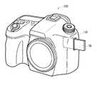
- the heat dissipation structure(for example, heat dissipation structure 1) described in the first to fifth embodiments and modifications is, for example, a memory card mounted on the electronic device (camera 100) shown in FIG. It can be applied to the card slot 110 or the like to be inserted.
- the present technologyhas been described above with reference to the first to fifth embodiments, modifications, and application examples, the present technology is not limited to the above embodiments and can be modified in various ways.
- the heat conductive membermay have a spring property and is not limited to this.
- a square spring, a pull spring, a torsion spring, a spring, or the likecan be used as the heat conductive member.
- a capillary pump, a loop heat pipe, a thermosiphon, a self-excited heat pipe, or the likecan be used.
- the heat dissipation structure of the present disclosurecan be applied to video cameras, projectors, monitors (televisions), smartphones and the like, in addition to the cameras shown in the application examples.
- the present technologycan also have the following configurations.
- a hollow structure having a thermal diode functionis included, and a heat conductive member that comes into contact with the heat source portion by elastic deformation is used, so that the contact area between the heat source portion and the heat conductive member is increased. It is possible to improve and improve the cooling efficiency.
- a heat dissipation structureincluding a support member that supports the heat conductive member.
- the support memberhas one surface facing the heat source portion and another surface opposite to the one surface.
- the heat radiating structure according to (2)wherein the fixed portion of the heat conductive member is fixed to the one surface of the support member.
- the support memberhas one surface facing the heat source portion and another surface opposite to the one surface.
- the heat radiating structure according to (2)wherein the fixed portion of the heat conductive member is fixed to the other surface of the support member.
- the support memberfurther has an opening at a predetermined position.
- the heat radiating structure according to (4), wherein the contact portion of the heat conductive memberis arranged on the one surface side of the support member via the opening.
- the support memberhas a support substrate and an accommodating portion for accommodating the heat source portion by combining with the support substrate.
- the heat radiating structureaccording to any one of (1) to (10), wherein the heat radiating member is arranged on the heat conductive member.
- the heat dissipation structureis A heat conductive member that includes a hollow structure having a thermal diode function and comes into contact with a heat source due to elastic deformation.
- An electronic devicehaving a support member that supports the heat conductive member.
Landscapes
- Physics & Mathematics (AREA)
- Engineering & Computer Science (AREA)
- Microelectronics & Electronic Packaging (AREA)
- Condensed Matter Physics & Semiconductors (AREA)
- General Physics & Mathematics (AREA)
- Computer Hardware Design (AREA)
- Power Engineering (AREA)
- Thermal Sciences (AREA)
- Cooling Or The Like Of Electrical Apparatus (AREA)
Abstract
Description
Translated fromJapanese本開示は、電子部品が発する熱を放熱または冷却するための放熱構造およびこれを備えた電子機器に関する。The present disclosure relates to a heat radiating structure for radiating or cooling the heat generated by an electronic component and an electronic device provided with the heat radiating structure.
例えば、特許文献1では、液晶ライトバルブ等の光学部品を冷却する冷却部の一部に熱伝導板を配置し、この熱伝導板とヒートパイプとを接続することで放熱量の増加を図ったプロジェクタ装置が開示されている。For example, in Patent Document 1, a heat conductive plate is arranged in a part of a cooling portion for cooling an optical component such as a liquid crystal light valve, and the heat radiation amount is increased by connecting the heat conductive plate and the heat pipe. The projector device is disclosed.
このように、電子機器では、熱源に対する冷却効率の向上が求められている。In this way, electronic devices are required to improve the cooling efficiency of heat sources.
冷却効率を向上させることが可能な放熱構造および電子機器を提供することが望ましい。It is desirable to provide a heat dissipation structure and electronic devices that can improve the cooling efficiency.
本開示の一実施形態の放熱構造は、熱ダイオード機能を有する中空構造を含むと共に、弾性変形により熱源部と接触する熱伝導部材と、熱伝導部材を支持する支持部材とを備えたものである。The heat dissipation structure of one embodiment of the present disclosure includes a hollow structure having a heat diode function, and includes a heat conductive member that comes into contact with a heat source portion due to elastic deformation, and a support member that supports the heat conductive member. ..
本開示の一実施形態の電子機器は、熱源部として発熱する電子部品と、電子部品で発生した熱を放熱する放熱構造とを備えたものであり、放熱構造として、上記本開示の一実施形態の放熱構造を有する。The electronic device of the embodiment of the present disclosure includes an electronic component that generates heat as a heat source portion and a heat radiating structure that dissipates heat generated by the electronic component. Has a heat dissipation structure.
本開示の一実施形態の放熱構造および一実施形態の電子機器では、熱ダイオード機能を有する中空構造を含むと共に、弾性変形により熱源部と接触する熱伝導部材を用いることにより、熱源部と熱伝導部材との接触面積が向上する。The heat dissipation structure of one embodiment and the electronic device of one embodiment of the present disclosure include a hollow structure having a heat diode function, and by using a heat conductive member that comes into contact with the heat source portion by elastic deformation, the heat conduction with the heat source portion. The contact area with the member is improved.
以下、本開示における実施の形態について、図面を参照して詳細に説明する。以下の説明は本開示の一具体例であって、本開示は以下の態様に限定されるものではない。また、本開示は、各図に示す各構成要素の配置や寸法、寸法比等についても、それらに限定されるものではない。なお、説明する順序は、下記の通りである。
1.第1の実施の形態(中空構造およびバネ性を有する熱伝導部材(板バネ)と収容部材とが一体形成された放熱構造の例)
1-1.放熱構造の構成
1-2.作用・効果
2.第2の実施の形態(中空構造およびバネ性を有する熱伝導部材(板バネ)を支持基板に固定した放熱構造の一例)
3.第3の実施の形態(中空構造およびバネ性を有する熱伝導部材(板バネ)を支持基板に固定した放熱構造の他の例)
4.第4の実施の形態(熱伝導部材として皿バネを用いた放熱構造の一例)
5.第5の実施の形態(熱伝導部材として皿バネを用いた放熱構造の他の例)
6.変形例(バッテリーを冷却するための放熱構造の例)
7.適用例Hereinafter, embodiments in the present disclosure will be described in detail with reference to the drawings. The following description is a specific example of the present disclosure, and the present disclosure is not limited to the following aspects. Further, the present disclosure is not limited to the arrangement, dimensions, dimensional ratio, etc. of each component shown in each figure. The order of explanation is as follows.
1. 1. 1st Embodiment (Example of a heat dissipation structure in which a heat conductive member (leaf spring) having a hollow structure and a spring property and a housing member are integrally formed)
1-1. Structure of heat dissipation structure 1-2. Action /
3. 3. Third Embodiment (Another example of a heat dissipation structure in which a heat conductive member (leaf spring) having a hollow structure and a spring property is fixed to a support substrate)
4. Fourth embodiment (an example of a heat dissipation structure using a disc spring as a heat conductive member)
5. Fifth Embodiment (another example of a heat dissipation structure using a disc spring as a heat conductive member)
6. Modification example (example of heat dissipation structure for cooling the battery)
7. Application example
<1.第1の実施の形態>
(1-1.放熱構造の構成)
図1は、本開示の第1の実施の形態に係る放熱構造(放熱構造1)の構成を、発熱部を有する電子部品(例えば、記憶媒体20)と共に模式的に表した斜視図である。図2は、図1に示したI-I線における放熱構造1および記憶媒体20の断面構造を模式的に表したものである。図3は、図1に示した放熱構造1の内部構造および記憶媒体20について説明するための透過斜視図である。この放熱構造1は、後述するカメラ100(図14参照)等の各種電子機器の内部に配置される電子部品の放熱または冷却に用いられるものである。本実施の形態の放熱構造1では、例えば、記憶媒体20において発生した熱を放熱または冷却するための熱伝導部材11が熱ダイオード機能を有する中空構造およびバネ性を有することにより、弾性変形によって記憶媒体20の発熱部(熱源)と、例えば面接触するように構成されたものである。<1. First Embodiment>
(1-1. Structure of heat dissipation structure)
FIG. 1 is a perspective view schematically showing a configuration of a heat radiating structure (heat radiating structure 1) according to the first embodiment of the present disclosure together with an electronic component having a heat generating portion (for example, a storage medium 20). FIG. 2 schematically shows a cross-sectional structure of the heat radiating structure 1 and the
放熱構造1は、熱伝導部材11と、熱伝導部材11を支持する支持部材12とを有している。支持部材12は、例えば支持基板13と収容部材14と有しており、この支持基板13と収容部材14とを組み合わせることで、例えば、記憶媒体20が挿入されるスロットXを構成している。The heat dissipation structure 1 has a heat
熱伝導部材11は、記憶媒体20の発熱部を冷却するためのものである。熱伝導部材11は、上記のように、熱ダイオード機能を有する中空構造およびバネ性を有する部材によって構成されている。熱伝導部材11は、板バネ形状を有するヒートパイプによって形成することができる。The heat
ヒートパイプは、中空なパイプの内部に、例えば水等の揮発しやすい液体(冷媒)が少量封入されると共に、パイプの内壁にウィックと呼ばれる毛細管構造を有するものである。ヒートパイプでは、高温部内壁で冷媒が熱を吸収して蒸発し、その蒸気がパイプ内の空間内を移動して低温部(冷却部)において冷却される。冷却された蒸気は、凝集して液体に戻り、パイプの内壁のウィックに吸収され、再び高温部に運ばれる。ヒートパイプでは、パイプ内の空間において、冷媒が上記のように高温部と低温部との間を循環することにより、高温部から低温部への熱移動が起こる。A heat pipe has a hollow pipe filled with a small amount of a volatile liquid (refrigerant) such as water, and has a capillary structure called a wick on the inner wall of the pipe. In the heat pipe, the refrigerant absorbs heat on the inner wall of the high temperature part and evaporates, and the vapor moves in the space inside the pipe and is cooled in the low temperature part (cooling part). The cooled vapor aggregates and returns to a liquid, is absorbed by the wick on the inner wall of the pipe, and is transported to the high temperature part again. In the heat pipe, heat is transferred from the high temperature part to the low temperature part by circulating the refrigerant between the high temperature part and the low temperature part in the space inside the pipe as described above.
熱伝導部材11は、例えば、支持部材12に固定される固定部11Aと、例えば図2に示したように、熱源である記憶媒体20の発熱部およびその近傍(具体的には、記憶媒体20の発熱部近傍のケース部分)と接触する接触部11Bとを有している。熱伝導部材11では、固定部11Aが上記低温部に相当し、接触部11Bが上記高温部に相当する。即ち、熱伝導部材11内部の冷媒は、接触部11Bにおいて、記憶媒体20の発熱部で発せられた熱を吸収して蒸発し、蒸気として固定部11Aに向かって移動する。固定部11Aに移動した冷媒(蒸気)は、冷却されて液体に戻り、熱伝導部材11内部のウィックに吸収され、重力や毛管力等によって接触部11Bに再び移動する。The heat
本実施の形態では、熱伝導部材11は、支持部材12を構成する収容部材14の、支持基板13と対向する上面部の一部を、例えば一辺を残して枠状に切り離し、その切り離された上面部を加工して形成されたものである。熱伝導部材11の固定部11Aは、収容部材14の枠部分と繋がっている。切り離された上面部は支持基板13側に折り曲げられており、記憶媒体20との接触部11Bを構成している。また、切り離された上面部の先端は、例えば支持基板13側とは反対方向に反っており、これにより、例えば記憶媒体20を挿入する際の熱伝導部材11への引っ掛かりを防いでいる。In the present embodiment, the heat
熱伝導部材11は、熱伝導性の高い材料を用いて形成することが好ましい。具体的な材料としては、例えば、ベリリウム銅、ベリリウム銅およびアルミニウム等が挙げられる。熱伝導部材11は、上記材料の中でも、ベリリウム銅を用いて形成することが好ましい。The heat
支持部材12、熱伝導部材11を支持すると共に、熱源となる記憶媒体20が収容されるものである。支持部材12は、上記のように、例えば、支持基板13と収容部材14とを有し、支持基板13と収容部材14とを組み合わせることで、例えば、記憶媒体20が挿入されるスロットXを構成している。スロットXの内部には、例えば、記憶媒体20の複数の配線22と電気的に接続される複数の端子15が設けられている。A
支持基板13は、例えば、収容部材14を支持すると共に、複数の端子15が設けられた一の面を有する、例えば板状部材であり、例えば、ガラスまたはエポキシ等を用いて形成することができる。収容部材14は、支持基板13と組み合わせることでスロットXを形成する、支持基板13の一の面と対向する上面部および側面部を有し、例えば、ベリリウム銅等を用いて形成することができる。本実施の形態では、収容部材14は、上面部の一部が熱伝導部材11を兼ねている。そのため、収容部材14は、熱伝導部材11と同様に、例えばベリリウム銅を用いて形成するようにしてもよい。また、収容部材14は、例えば、上面部の熱伝導部材11を構成する部分のみが中空なヒートパイプによって形成されていてもよいし、収容部材14全体が中空なヒートパイプによって形成されていてもよい。The
熱伝導部材11の固定部11Aには、さらに放熱部材16が設けられていてもよい。放熱部材16は、例えば、複数のフィンを用いて形成することができる。放熱部材16を設けることにより、固定部11Aにおける冷媒の放熱効率が向上し、熱伝導部材11の内部における効率よく熱移動が起こるようになる。A
記憶媒体20は、内部に発熱部を有するものであり、本開示の「熱源部」の一具体例に相当する。記憶媒体20は、例えば、メモリカードであり、内部に集積回路(IC)21と、IC21に接続された配線22とを有している。記憶媒体20では、例えばIC21が発熱する。The
(1-2.作用・効果)
本実施の形態の放熱構造1では、熱ダイオード機能を有する中空構造およびバネ性を有する部材を用いて熱伝導部材11を形成するようにした。これにより、熱伝導部材11は、弾性変形により、例えば、メモリカード等の記憶媒体20の発熱部(例えばIC21)に対して、面接触できるようになる。即ち、熱源部に対する熱伝導部材11の接触面積が向上する。以下、これについて説明する。(1-2. Action / effect)
In the heat dissipation structure 1 of the present embodiment, the heat
電子部品は、動作時に大きな熱を発生する。このため電子機器では、前述したように、高温による特性劣化等を回避するため、発生した熱を放散させ冷却する方法が開発されている。Electronic components generate a large amount of heat during operation. Therefore, as described above, in electronic devices, a method of dissipating and cooling the generated heat has been developed in order to avoid deterioration of characteristics due to high temperature.
動作時に大きな熱を発生する電子部品の一例としては、例えば、デジタルカメラ等の記憶媒体として用いられるメモリカードが挙げられるが、メモリカードは挿抜する電子部品であるため、周辺部品との熱的な接続が困難である。一般的な放熱方法としては、例えばグラファイトシートやヒートパイプ等の高熱伝導体をメモリカードに接触させることが考えられる。しかしながら、上記のような高熱伝導体は剛性が高いため、接触させるとメモリカードの挿抜ができなくなってしまう。An example of an electronic component that generates a large amount of heat during operation is a memory card used as a storage medium for a digital camera or the like. However, since the memory card is an electronic component to be inserted and removed, it is thermally connected to peripheral components. Difficult to connect. As a general heat dissipation method, it is conceivable to bring a high thermal conductor such as a graphite sheet or a heat pipe into contact with the memory card. However, since the high thermal conductor as described above has high rigidity, the memory card cannot be inserted or removed when it is brought into contact with the conductor.
これに対して、本実施の形態では、中空構造およびバネ性を有する部材を用いて熱伝導部材11を形成することにより、熱源となる記憶媒体20に対して、弾性変形によって面接触するようにした。これにより、記憶媒体20の挿抜を妨げることなく、記憶媒体20に対する熱伝導部材11の接触面積を向上させることが可能となる。On the other hand, in the present embodiment, by forming the heat
以上により、本実施の形態の放熱構造1では、中空構造およびバネ性を有する部材を用いて熱伝導部材11を形成するようにしたので、記憶媒体20に対して熱伝導部材11を弾性変形によって面接触させることができるようになり、記憶媒体20に対する熱伝導部材11の接触面積が向上する。よって、冷却効率を向上させることが可能となる。As described above, in the heat dissipation structure 1 of the present embodiment, since the heat
本実施の形態の放熱構造1は、上述したメモリカードのように、周辺部品との間に空隙を有し、熱的な接続が困難な電子部品の放熱手段として特に有効となる。The heat dissipation structure 1 of the present embodiment is particularly effective as a heat dissipation means for electronic components such as the memory card described above, which have a gap between the peripheral components and which are difficult to thermally connect.
また、本実施の形態では、中空構造およびバネ性を有する部材を用いて熱伝導部材11を形成するようにしたので、メモリカードのように、挿抜する電子部品の放熱構造としての耐久性を向上させることが可能となる。Further, in the present embodiment, since the heat
更に、本実施の形態の放熱構造1は、ベリリウム銅を用いて熱伝導部材11を形成することにより、一般的な銅板バネを用いた放熱構造と比較して、熱伝導率を大幅(例えば、約25倍)に向上させることが可能となる。更にまた、ベリリウム銅を用いた熱伝導部材11は、例えば銅ヒートパイプを用いた熱伝導部材11と比較して、バネ耐力を大幅(例えば、約30倍)に向上させることが可能となる。Further, in the heat dissipation structure 1 of the present embodiment, by forming the heat
次に、本開示の第2~第5の実施の形態および変形例ならびに適用例について説明する。以下では、上記第1の実施の形態と同様の構成要素については同一の符号を付し、適宜その説明を省略する。Next, the second to fifth embodiments and modifications of the present disclosure and application examples will be described. In the following, the same components as those in the first embodiment will be designated by the same reference numerals, and the description thereof will be omitted as appropriate.
<2.第2の実施の形態>
図4は、本開示の第2の実施の形態に係る放熱構造(放熱構造2)の構成を、発熱部を有する電子部品(例えば、記憶媒体20)と共に模式的に表した透過斜視図である。図5は、図4に示したII-II線における放熱構造2および記憶媒体20の断面構造を模式的に表したものである。この放熱構造2は、上記第1の実施の形態と同様に、後述するカメラ100等の各種電子機器の内部に配置される電子部品の放熱または冷却に用いられるものである。本実施の形態の放熱構造2では、例えば、記憶媒体20において発生した熱を放熱または冷却するための熱伝導部材31と、支持部材41とが別体として設けられ、熱伝導部材31が支持部材41を構成する支持基板42側に固定されたものである。<2. Second Embodiment>
FIG. 4 is a transmission perspective view schematically showing the configuration of the heat dissipation structure (heat dissipation structure 2) according to the second embodiment of the present disclosure together with an electronic component having a heat generating portion (for example, a storage medium 20). .. FIG. 5 schematically shows the cross-sectional structure of the
熱伝導部材31は、上記のように支持部材41とは別体で形成された以外は、上述した熱伝導部材11と同様の構成を有している。熱伝導部材31は、中空構造およびバネ性を有する部材によって構成され、例えば、板バネ形状を有するヒートパイプによって形成することができる。熱伝導部材31は、例えば、支持部材41を構成する例えば支持基板42に固定される固定部31Aと、熱源である記憶媒体20の発熱部と接触する接触部31Bとを有しており、固定部31Aは、支持基板42の一の面(上面:面42S1)の、収容部材43と組み合わせることによって形成されるスロットXの内部に固定されている。固定部31Aは、例えばはんだ等を用いて固定することができる。The heat
支持部材41は、例えば、支持基板42と収容部材43とを有し、支持基板42と収容部材43とを組み合わせることで、例えば、記憶媒体20が挿入されるスロットXを構成している。スロットXの内部には、図4等では示していないが、上記第1の実施の形態と同様に、例えば記憶媒体20の複数の配線22と電気的に接続される複数の端子が設けられている。The
支持基板42は、例えば、収容部材43を支持すると共に、複数の端子が設けられた一の面(面42S1)を有する、例えば板状部材であり、この面42S1には、熱伝導部材31の固定部31Aが固定されている。支持基板42は、例えば、セラミックス等を用いて形成することができる。その中でも、例えば、高い熱伝導性を有するアルミナ基板を用いて形成することにより、支持基板42を放熱部材として用いることができる。収容部材43は、支持基板42の面42S1と対向する上面部および側面部を有し、例えばステンレス等を用いて形成することができる。The
以上のように、本実施の形態では、熱伝導部材31と、支持部材41とを別部材として設け、熱伝導部材31の固定部31Aを、支持部材41を構成する支持基板42の上面(面42S1)に固定するようにした。このように、熱伝導部材31と、支持部材41とを別部材として設けた場合でも、上記第1の実施の形態と同様の効果を得ることができる。As described above, in the present embodiment, the heat
<3.第3の実施の形態>
図6は、本開示の第3の実施の形態に係る放熱構造(放熱構造3)の構成を、発熱部を有する電子部品(例えば、記憶媒体20)と共に模式的に表した透過斜視図である。図7は、図6に示したIII-III線における放熱構造3および記憶媒体20の断面構造を模式的に表したものである。この放熱構造3は、上記第1の実施の形態と同様に、後述するカメラ100等の各種電子機器の内部に配置される電子部品の放熱または冷却に用いられるものである。本実施の形態の放熱構造3では、熱伝導部材31の固定部31Aが、支持部材41を構成する支持基板42の面42S1とは反対側の他の面(下面:面42S2)側に固定され、熱伝導部材31の接触部31Bが、支持基板42に設けられた開口42Hを介して支持基板42の面42S1側に引き出されている点が、上記第2の実施の形態とは異なる。<3. Third Embodiment>
FIG. 6 is a transmission perspective view schematically showing the configuration of the heat dissipation structure (heat dissipation structure 3) according to the third embodiment of the present disclosure together with an electronic component having a heat generating portion (for example, a storage medium 20). .. FIG. 7 schematically shows the cross-sectional structure of the heat dissipation structure 3 and the
熱伝導部材31は、上述した第2の実施の形態と同様の構成を有している。The heat
支持部材41、例えば、支持基板42と収容部材43とを有し、支持基板42と収容部材43とを組み合わせることで、例えば、記憶媒体20が挿入されるスロットXを構成している。図6等では示していないが、スロットXの内部には、上記第1の実施の形態と同様に、例えば、記憶媒体20の複数の配線22と電気的に接続される複数の端子が設けられている。更に、本実施の形態では、支持基板42には、支持基板42の面42S2側に固定された熱伝導部材31の接触部31Bを、面42S1側に引き出し可能な開口42Hが、例えばスロットXに対応する位置に設けられている。It has a
更に、支持基板42の面42S2に固定された熱伝導部材31の固定部31Aには、放熱部材44が設けられていてもよい。放熱部材44は、上記第1の実施の形態と同様に、例えば、複数のフィンを用いて形成することができる。Further, the
以上のように、本実施の形態では、熱伝導部材31の固定部31Aを、支持部材41を構成する支持基板42の下面(面42S2)に固定し、支持基板42に設けられた開口42Hを介して支持基板42の面42S1側に引き出すようにした。このような構成においても、上記第1の実施の形態と同様の効果を得ることができる。As described above, in the present embodiment, the fixing
また、本実施の形態では、熱伝導部材31の固定部31Aを支持基板42の下面(面42S2)に固定するようにしたので、熱伝導部材31に対して放熱部材44を配設することが可能となる。よって、上記第2の実施の形態と比較して、冷却効率を向上させることが可能となる。Further, in the present embodiment, since the fixing
なお、図7では、熱伝導部材31の固定部31Aを支持基板42の下面(面42S2)に直接固定し、支持基板42側とは反対側の面に放熱部材44を配設した例を示したが、これに限らない。例えば、熱伝導部材31の固定部31Aと支持基板42の下面(面42S2)との間に放熱部材44を配置し、放熱部材44を介して支持基板42の下面(面42S2)に固定部31Aを固定するようにしてもよい。Note that FIG. 7 shows an example in which the fixing
<4.第4の実施の形態>
図8は、本開示の第4の実施の形態に係る放熱構造(放熱構造4)の構成を、発熱部を有する電子部品(例えば、記憶媒体20)と共に模式的に表した透過斜視図である。図9は、図8に示したIV-IV線における放熱構造4および記憶媒体20の断面構造を模式的に表したものである。この放熱構造4は、上記第1の実施の形態と同様に、後述するカメラ100等の各種電子機器の内部に配置される電子部品の放熱または冷却に用いられるものである。本実施の形態の放熱構造4では、皿バネ形状を有する熱伝導部材51を用いた点が、上記第2の実施の形態とは異なる。<4. Fourth Embodiment>
FIG. 8 is a transmission perspective view schematically showing the configuration of the heat dissipation structure (heat dissipation structure 4) according to the fourth embodiment of the present disclosure together with an electronic component having a heat generating portion (for example, a storage medium 20). .. FIG. 9 schematically shows the cross-sectional structure of the heat dissipation structure 4 and the
熱伝導部材51は、皿バネ形状を有する以外は、上述した熱伝導部材11と同様の構成を有している。熱伝導部材51は、例えば皿バネ形状を有するヒートパイプによって形成されたものである。皿バネは、例えば、中心に穴の開いた円板状の板を円錐状にし、底のない皿のような形状をしたものである。本実施の形態の熱伝導部材51は、例えば、円錐下側部分に、例えば支持基板42の面42S1と略平行な面を形成する周縁部を有しており、この周縁部が支持基板42の面42S1と固定される固定部51Aを構成している。支持基板42の面42S1に固定された熱伝導部材51は、スロットX内部において円錐上側部分が、例えば支持基板42の面42S1に対して法線方向に突出した形状となっており、スロットXに記憶媒体20を挿入した際に、円錐上側部分が撓むことにより、記憶媒体20の発熱部(例えば、IC21)と面接触する。即ち、円錐上側部分が接触部51Bを構成している。The heat
以上のように、本実施の形態では、皿バネ形状を有する熱伝導部材51を用いるようにした。このような構成においても、上記第1の実施の形態と同様の効果を得ることができる。As described above, in the present embodiment, the heat
<5.第5の実施の形態>
図10は、本開示の第5の実施の形態に係る放熱構造(放熱構造5)の構成を、発熱部を有する電子部品(例えば、記憶媒体20)と共に模式的に表した斜視図である。図11は、図10に示したV-V線における放熱構造5および記憶媒体20の断面構造を模式的に表したものである。この放熱構造5は、上記第1の実施の形態と同様に、後述するカメラ100等の各種電子機器の内部に配置される電子部品の放熱または冷却に用いられるものである。本実施の形態の放熱構造5では、熱伝導部材51の固定部51Aが、支持部材41を構成する支持基板42の面42S1とは反対側の他の面(下面:面42S2)側に固定され、熱伝導部材51の接触部51Bが、支持基板42に設けられた開口42Hを介して支持基板42の面42S1側に突出している点が、上記第4の実施の形態とは異なる。<5. Fifth Embodiment>
FIG. 10 is a perspective view schematically showing the configuration of the heat radiating structure (heat radiating structure 5) according to the fifth embodiment of the present disclosure together with an electronic component having a heat generating portion (for example, a storage medium 20). FIG. 11 schematically shows the cross-sectional structure of the
熱伝導部材51は、上述した第4の実施の形態と同様の構成を有している。The heat
支持部材41、上述した第3の実施の形態と同様の構成を有しており、熱伝導部材51の接触部51Bとなる円錐上側部分は、例えばスロットXに対応する位置に設けられた開口42Hを介して支持基板42の面42S1側に突出している。The
更に、支持基板42の面42S2に固定された熱伝導部材51の固定部51Aには、上記第3の実施の形態と同様に、例えば複数のフィンからなる放熱部材44が設けられていてもよい。Further, the fixing
以上のように、本実施の形態では、熱伝導部材51の固定部51Aを、支持部材41を構成する支持基板42の下面(面42S2)に固定し、接触部51Bとなる円錐上側部分を、支持基板42に設けられた開口42Hを介して支持基板42の面42S1側に突出させるようにした。このような構成においても、上記第1の実施の形態と同様の効果を得ることができる。As described above, in the present embodiment, the fixing
また、本実施の形態では、熱伝導部材51の固定部51Aを支持基板42の下面(面42S2)に固定するようにしたので、熱伝導部材51に対して放熱部材44を配設することが可能となる。よって、上記第4の実施の形態と比較して、冷却効率を向上させることが可能となる。Further, in the present embodiment, since the fixing
なお、図11では、熱伝導部材51の固定部51Aを支持基板42の下面(面42S2)に直接固定し、支持基板42側とは反対側の面に放熱部材44を配設した例を示したが、これに限らない。例えば、上記第3の実施の形態と同様に、熱伝導部材51の固定部51Aと支持基板42の下面(面42S2)との間に放熱部材44を配置し、放熱部材44を介して支持基板42の下面(面42S2)に固定部51Aを固定するようにしてもよい。Note that FIG. 11 shows an example in which the fixing
<6.変形例>
図12は、本開示の変形例に係る放熱構造(放熱構造6)の外観構成を、発熱部を有する電子部品(例えば、バッテリー80)と共に模式的に表した斜視図である。図13は、図12に示したVI-VI線における放熱構造6の断面構造をバッテリー80と共に模式的に表したものである。この放熱構造6は、上記第1の実施の形態と同様に、後述するカメラ100等の各種電子機器の内部に配置される電子部品の放熱または冷却に用いられるものである。上記第1~第5の実施の形態では、熱源部として記憶媒体20を想定した例を示したが、本技術は、その他の電子部品の放熱手段として用いることができる。本変形例では、例えばバッテリー80を熱源部とした際の放熱構造6について説明する。<6. Modification example>
FIG. 12 is a perspective view schematically showing the external configuration of the heat radiating structure (heat radiating structure 6) according to the modified example of the present disclosure together with an electronic component having a heat generating portion (for example, a battery 80). FIG. 13 schematically shows the cross-sectional structure of the heat dissipation structure 6 in the VI-VI line shown in FIG. 12 together with the
放熱構造6は、本開示の「熱伝導部材」として、例えば、バッテリーバネ61およびバッテリー端子62の2つを有している。また、放熱構造6は、本開示の「支持部材」として、バッテリーボックス71を有している。バッテリーボックス71は、例えば、バッテリーバネ61およびバッテリー端子62が固定される支持部72と、バッテリー80を収容する収容部73と有している。バッテリーボックス71は、さらに、支持部72に配設されたバッテリー基板74を有しており、バッテリーバネ61およびバッテリー端子62は、このバッテリー基板74を介して支持部72に固定されている。The heat dissipation structure 6 has, for example, a
バッテリーバネ61は、例えば、バッテリーボックス71に挿入されたバッテリー80を取り出すためのものであり、例えば、円錐形状を有するコイル状のヒートパイプによって形成することができる。バッテリーバネ61では、円錐下側部分が固定部61Aとしてバッテリー基板74に固定されており、円錐上側部分が接触部61Bとしてバッテリー80と接触するようになっている。The
バッテリー端子62は、バッテリー80と電気的に接続するためのものであり、例えば、上記第1の実施の形態等と同様に、板バネ形状を有するヒートパイプによって形成することができる。バッテリー端子62は、バッテリーバネ61と同様に、固定部62Aおよび接触部62Bを有し、固定部62Aがバッテリー基板74に固定され、接触部61Bとしてバッテリー80と接触するようになっている。The
以上のように、本変形例の放熱構造6では、バッテリー80の熱は、中空構造およびバネ性を有するバッテリーバネ61およびバッテリー端子62の2つを介してバッテリーボックス71に放熱されるようになる。よって、上記第1の実施の形態と同様に、バッテリー80を効率よく冷却することが可能となる。As described above, in the heat dissipation structure 6 of the present modification, the heat of the
<7.適用例>
上記第1~第5の実施の形態および変形例で説明した放熱構造(例えば、放熱構造1)は、例えば、図14に示した電子機器(カメラ100)等に搭載された、例えばメモリカードを挿入するカードスロット110等に適用することができる。<7. Application example>
The heat dissipation structure (for example, heat dissipation structure 1) described in the first to fifth embodiments and modifications is, for example, a memory card mounted on the electronic device (camera 100) shown in FIG. It can be applied to the
以上、第1~第5の実施の形態および変形例ならびに適用例を挙げて本技術を説明したが、本技術は上記実施の形態等に限定されるものではなく、種々変形が可能である。例えば、上記実施の形態等では、熱伝導部材として板バネ、皿バネおよびコイルバネを用いて例を示したが、熱伝導部材はバネ性を有していればよく、これに限定されるものではない。例えば、熱伝導部材は、角バネ、引きバネ、ねじりバネおよびゼンマイバネ等を用いることができる。この他、熱伝導部材は、キャピラリポンプ、ループヒートパイプ、サーモサイホンおよび自励式ヒートパイプ等を用いることができる。更に、本開示の放熱構造は、適用例において示したカメラ以外に、ビデオカメラ、プロジェクタ、モニタ(テレビ)およびスマートフォン等にも適用することができる。Although the present technology has been described above with reference to the first to fifth embodiments, modifications, and application examples, the present technology is not limited to the above embodiments and can be modified in various ways. For example, in the above-described embodiment and the like, an example is shown in which a leaf spring, a disc spring and a coil spring are used as the heat conductive member, but the heat conductive member may have a spring property and is not limited to this. No. For example, as the heat conductive member, a square spring, a pull spring, a torsion spring, a spring, or the like can be used. In addition, as the heat conductive member, a capillary pump, a loop heat pipe, a thermosiphon, a self-excited heat pipe, or the like can be used. Further, the heat dissipation structure of the present disclosure can be applied to video cameras, projectors, monitors (televisions), smartphones and the like, in addition to the cameras shown in the application examples.
なお、本明細書中に記載された効果はあくまで例示であって限定されるものではなく、また、他の効果があってもよい。Note that the effects described in this specification are merely examples and are not limited, and other effects may be obtained.
なお、本技術は以下のような構成を取ることも可能である。以下の構成の本技術によれば、熱ダイオード機能を有する中空構造を含むと共に、弾性変形により熱源部と接触する熱伝導部材を用いるようにしたので、熱源部と熱伝導部材との接触面積が向上し、冷却効率を向上させることが可能となる。
(1)
熱ダイオード機能を有する中空構造を含むと共に、弾性変形により熱源部と接触する熱伝導部材と、
前記熱伝導部材を支持する支持部材と
を備えた放熱構造。
(2)
前記熱伝導部材は、前記熱源部に接触する接触部と、前記支持部材に固定される固定部とを有する、前記(1)に記載の放熱構造。
(3)
前記支持部材は、前記熱源部と対向する一の面と前記一の面とは反対側の他の面とを有し、
前記熱伝導部材の前記固定部は、前記支持部材の前記一の面に固定されている、前記(2)に記載の放熱構造。
(4)
前記支持部材は、前記熱源部と対向する一の面と前記一の面とは反対側の他の面とを有し、
前記熱伝導部材の前記固定部は、前記支持部材の前記他の面に固定されている、前記(2)に記載の放熱構造。
(5)
前記支持部材は、さらに、所定の位置に開口を有し、
前記熱伝導部材の前記接触部は、前記開口を介して前記支持部材の前記一の面側に配置されている、前記(4)に記載の放熱構造。
(6)
前記支持部材は、支持基板と、前記支持基板と組み合わせることにより前記熱源部を収容する収容部とを有し、
前記熱伝導部材は、前記収容部の前記支持基板との対向面に形成されている、前記(1)乃至(5)のうちのいずれか1つに記載の放熱構造。
(7)
前記熱伝導部材と前記支持部材とは、一体形成されている、前記(1)乃至(6)のうちのいずれか1つに記載の放熱構造。
(8)
前記熱伝導部材は、ベリリウム銅を用いて形成されている、前記(1)乃至(7)のうちのいずれか1つに記載の放熱構造。
(9)
前記熱伝導部材は、バネ性を有するヒートパイプである、前記(1)乃至(8)のうちのいずれか1つに記載の放熱構造。
(10)
前記ヒートパイプは、板バネ形状または皿バネ形状を有する、前記(9)に記載の放熱構造。
(11)
放熱部材をさらに有し、
前記放熱部材は、前記熱伝導部材に配設されている、前記(1)乃至(10)のうちのいずれか1つに記載の放熱構造。
(12)
前記支持部材が前記放熱部材を兼ねている、前記(11)に記載の放熱構造。
(13)
熱源部として発熱する電子部品と、前記電子部品で発生した熱を放熱する放熱構造とを備え、
前記放熱構造は、
熱ダイオード機能を有する中空構造を含むと共に、弾性変形により熱源部と接触する熱伝導部材と、
前記熱伝導部材を支持する支持部材と
を有する電子機器。
(14)
前記電子部品は、記憶媒体またはバッテリーである、前記(13)に記載の電子機器。The present technology can also have the following configurations. According to this technology having the following configuration, a hollow structure having a thermal diode function is included, and a heat conductive member that comes into contact with the heat source portion by elastic deformation is used, so that the contact area between the heat source portion and the heat conductive member is increased. It is possible to improve and improve the cooling efficiency.
(1)
A heat conductive member that includes a hollow structure having a thermal diode function and comes into contact with a heat source due to elastic deformation.
A heat dissipation structure including a support member that supports the heat conductive member.
(2)
The heat radiating structure according to (1), wherein the heat conductive member has a contact portion that contacts the heat source portion and a fixing portion that is fixed to the support member.
(3)
The support member has one surface facing the heat source portion and another surface opposite to the one surface.
The heat radiating structure according to (2), wherein the fixed portion of the heat conductive member is fixed to the one surface of the support member.
(4)
The support member has one surface facing the heat source portion and another surface opposite to the one surface.
The heat radiating structure according to (2), wherein the fixed portion of the heat conductive member is fixed to the other surface of the support member.
(5)
The support member further has an opening at a predetermined position.
The heat radiating structure according to (4), wherein the contact portion of the heat conductive member is arranged on the one surface side of the support member via the opening.
(6)
The support member has a support substrate and an accommodating portion for accommodating the heat source portion by combining with the support substrate.
The heat radiating structure according to any one of (1) to (5), wherein the heat conductive member is formed on a surface of the accommodating portion facing the support substrate.
(7)
The heat radiating structure according to any one of (1) to (6), wherein the heat conductive member and the support member are integrally formed.
(8)
The heat radiating structure according to any one of (1) to (7) above, wherein the heat conductive member is formed of beryllium copper.
(9)
The heat radiating structure according to any one of (1) to (8) above, wherein the heat conductive member is a heat pipe having a spring property.
(10)
The heat dissipation structure according to (9) above, wherein the heat pipe has a leaf spring shape or a disc spring shape.
(11)
It also has a heat dissipation member,
The heat radiating structure according to any one of (1) to (10), wherein the heat radiating member is arranged on the heat conductive member.
(12)
The heat dissipation structure according to (11) above, wherein the support member also serves as the heat dissipation member.
(13)
It is equipped with an electronic component that generates heat as a heat source unit and a heat dissipation structure that dissipates heat generated by the electronic component.
The heat dissipation structure is
A heat conductive member that includes a hollow structure having a thermal diode function and comes into contact with a heat source due to elastic deformation.
An electronic device having a support member that supports the heat conductive member.
(14)
The electronic device according to (13) above, wherein the electronic component is a storage medium or a battery.
本出願は、日本国特許庁において2020年2月28日に出願された日本特許出願番号2020-033586号を基礎として優先権を主張するものであり、この出願の全ての内容を参照によって本出願に援用する。This application claims priority based on Japanese Patent Application No. 2020-033586 filed on February 28, 2020 at the Japan Patent Office, and this application is made by referring to all the contents of this application. Invite to.
当業者であれば、設計上の要件や他の要因に応じて、種々の修正、コンビネーション、サブコンビネーション、および変更を想到し得るが、それらは添付の請求の範囲やその均等物の範囲に含まれるものであることが理解される。One of ordinary skill in the art can conceive of various modifications, combinations, sub-combinations, and changes, depending on design requirements and other factors, which are included in the appended claims and their equivalents. It is understood that it is one of ordinary skill in the art.
Claims (14)
Translated fromJapanese前記熱伝導部材を支持する支持部材と
を備えた放熱構造。A heat conductive member that includes a hollow structure having a thermal diode function and comes into contact with a heat source due to elastic deformation.
A heat dissipation structure including a support member that supports the heat conductive member.
前記熱伝導部材の前記固定部は、前記支持部材の前記一の面に固定されている、請求項2に記載の放熱構造。The support member has one surface facing the heat source portion and another surface opposite to the one surface.
The heat radiating structure according to claim 2, wherein the fixed portion of the heat conductive member is fixed to the one surface of the support member.
前記熱伝導部材の前記固定部は、前記支持部材の前記他の面に固定されている、請求項2に記載の放熱構造。The support member has one surface facing the heat source portion and another surface opposite to the one surface.
The heat dissipation structure according to claim 2, wherein the fixed portion of the heat conductive member is fixed to the other surface of the support member.
前記熱伝導部材の前記接触部は、前記開口を介して前記支持部材の前記一の面側に配置されている、請求項4に記載の放熱構造。The support member further has an opening at a predetermined position.
The heat dissipation structure according to claim 4, wherein the contact portion of the heat conductive member is arranged on the one surface side of the support member via the opening.
前記熱伝導部材は、前記収容部の前記支持基板との対向面に形成されている、請求項1に記載の放熱構造。The support member has a support substrate and an accommodating portion for accommodating the heat source portion by combining with the support substrate.
The heat radiating structure according to claim 1, wherein the heat conductive member is formed on a surface of the accommodating portion facing the support substrate.
前記放熱部材は、前記熱伝導部材に配設されている、請求項1に記載の放熱構造。It also has a heat dissipation member,
The heat radiating structure according to claim 1, wherein the heat radiating member is arranged on the heat conductive member.
前記放熱構造は、
熱ダイオード機能を有する中空構造を含むと共に、弾性変形により熱源部と接触する熱伝導部材と、
前記熱伝導部材を支持する支持部材と
を有する電子機器。It is equipped with an electronic component that generates heat as a heat source unit and a heat dissipation structure that dissipates heat generated by the electronic component.
The heat dissipation structure is
A heat conductive member that includes a hollow structure having a thermal diode function and comes into contact with a heat source due to elastic deformation.
An electronic device having a support member that supports the heat conductive member.
Applications Claiming Priority (2)
| Application Number | Priority Date | Filing Date | Title |
|---|---|---|---|
| JP2020-033586 | 2020-02-28 | ||
| JP2020033586 | 2020-02-28 |
Publications (1)
| Publication Number | Publication Date |
|---|---|
| WO2021172122A1true WO2021172122A1 (en) | 2021-09-02 |
Family
ID=77490953
Family Applications (1)
| Application Number | Title | Priority Date | Filing Date |
|---|---|---|---|
| PCT/JP2021/005800CeasedWO2021172122A1 (en) | 2020-02-28 | 2021-02-17 | Heat dissipation structure and electronic device |
Country Status (1)
| Country | Link |
|---|---|
| WO (1) | WO2021172122A1 (en) |
Citations (7)
| Publication number | Priority date | Publication date | Assignee | Title |
|---|---|---|---|---|
| JPH0566095A (en)* | 1991-04-09 | 1993-03-19 | Akutoronikusu Kk | Heat joint device and manufacture thereof |
| JPH06129783A (en)* | 1992-10-13 | 1994-05-13 | Fujikura Ltd | Heat dissipation wall member |
| JPH10198462A (en)* | 1997-01-14 | 1998-07-31 | Fujitsu Ltd | Electronic device having IC card slot |
| JP2000349214A (en)* | 1999-06-04 | 2000-12-15 | Mitsubishi Electric Corp | Anti-vibration device with heat transfer structure |
| JP2005228954A (en)* | 2004-02-13 | 2005-08-25 | Fujitsu Ltd | Thermal conduction mechanism, heat dissipation system, and communication device |
| JP2008147525A (en)* | 2006-12-12 | 2008-06-26 | Sumitomo Electric Ind Ltd | Heat dissipating component and heat dissipating component equipment |
| CN205232671U (en)* | 2015-12-29 | 2016-05-11 | 宁德时代新能源科技股份有限公司 | Heat conduction shell fragment and install heat -generating body of this heat conduction shell fragment |
- 2021
- 2021-02-17WOPCT/JP2021/005800patent/WO2021172122A1/ennot_activeCeased
Patent Citations (7)
| Publication number | Priority date | Publication date | Assignee | Title |
|---|---|---|---|---|
| JPH0566095A (en)* | 1991-04-09 | 1993-03-19 | Akutoronikusu Kk | Heat joint device and manufacture thereof |
| JPH06129783A (en)* | 1992-10-13 | 1994-05-13 | Fujikura Ltd | Heat dissipation wall member |
| JPH10198462A (en)* | 1997-01-14 | 1998-07-31 | Fujitsu Ltd | Electronic device having IC card slot |
| JP2000349214A (en)* | 1999-06-04 | 2000-12-15 | Mitsubishi Electric Corp | Anti-vibration device with heat transfer structure |
| JP2005228954A (en)* | 2004-02-13 | 2005-08-25 | Fujitsu Ltd | Thermal conduction mechanism, heat dissipation system, and communication device |
| JP2008147525A (en)* | 2006-12-12 | 2008-06-26 | Sumitomo Electric Ind Ltd | Heat dissipating component and heat dissipating component equipment |
| CN205232671U (en)* | 2015-12-29 | 2016-05-11 | 宁德时代新能源科技股份有限公司 | Heat conduction shell fragment and install heat -generating body of this heat conduction shell fragment |
Similar Documents
| Publication | Publication Date | Title |
|---|---|---|
| US11379021B2 (en) | Heat dissipation module | |
| JP4929400B2 (en) | Electronic system with free space optical elements | |
| US8267159B2 (en) | Thermal module | |
| US7866375B2 (en) | Heat dissipation device with heat pipes | |
| US20070217162A1 (en) | Heat dissipation device | |
| US9578781B2 (en) | Heat management for electronic enclosures | |
| JP2008140924A (en) | Electronics | |
| US20130206367A1 (en) | Heat dissipating module | |
| JP6885194B2 (en) | Electronics | |
| JP2021136452A (en) | Devices and methods for dissipating heat in multiple semiconductor device modules | |
| JP2016100426A (en) | Communication module | |
| US20060032617A1 (en) | Heat sink electronic components | |
| JP4191160B2 (en) | Back panel of backlight module | |
| US20110075362A1 (en) | Electronic device | |
| JP4438526B2 (en) | Power component cooling system | |
| US20190223325A1 (en) | Optical module | |
| JP6281622B1 (en) | Cooling device, mounting method, cooling structure | |
| US20070295488A1 (en) | Thermosyphon for operation in multiple orientations relative to gravity | |
| WO2021172122A1 (en) | Heat dissipation structure and electronic device | |
| WO2013089162A1 (en) | Cooling structure for thin-profile electronics, and electronic device employing same | |
| US12061369B2 (en) | Heat dissipation structure for optical module and communications device | |
| JP5018555B2 (en) | Cooling module and composite mounting board | |
| JP7115032B2 (en) | substrate | |
| US10537043B2 (en) | Electronic apparatus | |
| US20140150996A1 (en) | Cooling device, and electronic apparatus with the cooling device |
Legal Events
| Date | Code | Title | Description |
|---|---|---|---|
| 121 | Ep: the epo has been informed by wipo that ep was designated in this application | Ref document number:21761773 Country of ref document:EP Kind code of ref document:A1 | |
| NENP | Non-entry into the national phase | Ref country code:DE | |
| 122 | Ep: pct application non-entry in european phase | Ref document number:21761773 Country of ref document:EP Kind code of ref document:A1 | |
| NENP | Non-entry into the national phase | Ref country code:JP |