WO2021171487A1 - Image correction method, imaging device, and inspection device - Google Patents
Image correction method, imaging device, and inspection deviceDownload PDFInfo
- Publication number
- WO2021171487A1 WO2021171487A1PCT/JP2020/008044JP2020008044WWO2021171487A1WO 2021171487 A1WO2021171487 A1WO 2021171487A1JP 2020008044 WJP2020008044 WJP 2020008044WWO 2021171487 A1WO2021171487 A1WO 2021171487A1
- Authority
- WO
- WIPO (PCT)
- Prior art keywords
- light source
- image
- source color
- correction amount
- correction
- Prior art date
- Legal status (The legal status is an assumption and is not a legal conclusion. Google has not performed a legal analysis and makes no representation as to the accuracy of the status listed.)
- Ceased
Links
Images


Classifications
- H—ELECTRICITY
- H04—ELECTRIC COMMUNICATION TECHNIQUE
- H04N—PICTORIAL COMMUNICATION, e.g. TELEVISION
- H04N17/00—Diagnosis, testing or measuring for television systems or their details
- H04N17/002—Diagnosis, testing or measuring for television systems or their details for television cameras
- H—ELECTRICITY
- H04—ELECTRIC COMMUNICATION TECHNIQUE
- H04N—PICTORIAL COMMUNICATION, e.g. TELEVISION
- H04N1/00—Scanning, transmission or reproduction of documents or the like, e.g. facsimile transmission; Details thereof
- H04N1/46—Colour picture communication systems
- H04N1/56—Processing of colour picture signals
- H04N1/58—Edge or detail enhancement; Noise or error suppression, e.g. colour misregistration correction
- H—ELECTRICITY
- H04—ELECTRIC COMMUNICATION TECHNIQUE
- H04N—PICTORIAL COMMUNICATION, e.g. TELEVISION
- H04N23/00—Cameras or camera modules comprising electronic image sensors; Control thereof
- H04N23/10—Cameras or camera modules comprising electronic image sensors; Control thereof for generating image signals from different wavelengths
- H04N23/125—Colour sequential image capture, e.g. using a colour wheel
- H—ELECTRICITY
- H04—ELECTRIC COMMUNICATION TECHNIQUE
- H04N—PICTORIAL COMMUNICATION, e.g. TELEVISION
- H04N23/00—Cameras or camera modules comprising electronic image sensors; Control thereof
- H04N23/50—Constructional details
- H04N23/55—Optical parts specially adapted for electronic image sensors; Mounting thereof
- H—ELECTRICITY
- H04—ELECTRIC COMMUNICATION TECHNIQUE
- H04N—PICTORIAL COMMUNICATION, e.g. TELEVISION
- H04N23/00—Cameras or camera modules comprising electronic image sensors; Control thereof
- H04N23/56—Cameras or camera modules comprising electronic image sensors; Control thereof provided with illuminating means
- H—ELECTRICITY
- H04—ELECTRIC COMMUNICATION TECHNIQUE
- H04N—PICTORIAL COMMUNICATION, e.g. TELEVISION
- H04N23/00—Cameras or camera modules comprising electronic image sensors; Control thereof
- H04N23/60—Control of cameras or camera modules
- H—ELECTRICITY
- H04—ELECTRIC COMMUNICATION TECHNIQUE
- H04N—PICTORIAL COMMUNICATION, e.g. TELEVISION
- H04N23/00—Cameras or camera modules comprising electronic image sensors; Control thereof
- H04N23/80—Camera processing pipelines; Components thereof
- H04N23/84—Camera processing pipelines; Components thereof for processing colour signals
- H04N23/88—Camera processing pipelines; Components thereof for processing colour signals for colour balance, e.g. white-balance circuits or colour temperature control
- H—ELECTRICITY
- H04—ELECTRIC COMMUNICATION TECHNIQUE
- H04N—PICTORIAL COMMUNICATION, e.g. TELEVISION
- H04N25/00—Circuitry of solid-state image sensors [SSIS]; Control thereof
- H04N25/60—Noise processing, e.g. detecting, correcting, reducing or removing noise
- H04N25/61—Noise processing, e.g. detecting, correcting, reducing or removing noise the noise originating only from the lens unit, e.g. flare, shading, vignetting or "cos4"
- H04N25/611—Correction of chromatic aberration
- H—ELECTRICITY
- H05—ELECTRIC TECHNIQUES NOT OTHERWISE PROVIDED FOR
- H05K—PRINTED CIRCUITS; CASINGS OR CONSTRUCTIONAL DETAILS OF ELECTRIC APPARATUS; MANUFACTURE OF ASSEMBLAGES OF ELECTRICAL COMPONENTS
- H05K13/00—Apparatus or processes specially adapted for manufacturing or adjusting assemblages of electric components
- H05K13/08—Monitoring manufacture of assemblages
- H05K13/081—Integration of optical monitoring devices in assembly lines; Processes using optical monitoring devices specially adapted for controlling devices or machines in assembly lines
- H05K13/0812—Integration of optical monitoring devices in assembly lines; Processes using optical monitoring devices specially adapted for controlling devices or machines in assembly lines the monitoring devices being integrated in the mounting machine, e.g. for monitoring components, leads, component placement
Definitions
- This specificationdiscloses an image correction method, an imaging device, and an inspection device.
- an image pickup apparatus of this typea device having a plurality of light sources for irradiating light of a plurality of colors and irradiating light from one of a plurality of light sources to image a subject has been proposed. (See, for example, Patent Document 1).
- this image pickup apparatusan appropriate value of resolution is selected and chromatic aberration is corrected according to the light source color of the selected light source.
- the original images of the respective light source colors obtained by irradiating each light source and capturing the same subjectare obtained, and the original images are superimposed.
- a pseudo color composite imagemay be generated.
- the correction amount of the distortion aberration and the correction amount of the chromatic aberrationare used to correct each original image, it takes time and effort to correct the original image, and it takes time to generate the composite image.
- the main purpose of the present disclosureis to reduce the trouble of correcting the distortion and chromatic aberration of the original image and enable the rapid generation of a composite image.
- the image correction method of the present disclosureis This is an image correction method for correcting the original image when a composite image is generated by superimposing a plurality of original images captured under the respective illuminations of a plurality of different light source colors.
- AAmong the reference images for each light source color captured by the member provided with the reference mark under the respective illumination of each light source color, the position of the reference mark recognized from the reference image of a specific light source color is determined.
- the correction amount for correcting the position of the reference mark recognized from the reference image of the specific light source color to the reference position of the reference mark in the reference image of the specific light source coloris obtained.
- the position of the reference mark recognized from the reference image of another light source coloris corrected to the reference position of the reference mark in the reference image of a specific light source color instead of the reference position of the reference mark in the reference image of another light source color.
- the amount of correction for thisis obtained for each of the other light source colors. Therefore, it is possible to set a correction amount that combines the correction of the distortion aberration and the correction of the chromatic aberration in association with each light source color.
- the distortion aberration and the chromatic aberration of the original imageare collectively corrected by using the correction amount associated with each light source color. Therefore, as compared with the case where the correction amounts of the distortion aberration and the chromatic aberration are corrected separately, the labor of correcting the distortion aberration and the chromatic aberration of the original image is reduced, and the composite image can be quickly generated. be able to.
- Explanatory drawing which shows an example of setting the correction amount of each light source.A flowchart showing an example of mounting inspection processing.
- FIG. 1is a configuration diagram showing an outline of the configuration of the component mounting machine 10 of the present embodiment.
- FIG. 2is a configuration diagram showing an outline of the configuration of the mark camera 50.
- FIG. 3is a view A of the epi-illumination light source 52.
- FIG. 4is a B view of the side emitting light source 54.
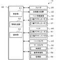
- FIG. 5is a block diagram showing a configuration related to control of the component mounting machine 10.
- the left-right direction in FIG. 1is the X-axis direction
- the front (front) rear (back) directionis the Y-axis direction
- the vertical directionis the Z-axis direction.
- a plurality of component mounting machines 10are arranged side by side in the substrate transport direction (X-axis direction) to form a production line.
- the component mounting machine 10includes a feeder 20, a substrate transfer device 22, a head 40 having a suction nozzle 45 for sucking parts, a head moving device 30 for moving the head 40, and a parts camera 23. And a mark camera 50. These are housed in a housing 12 installed on the base 11.
- the feeder 20is configured as a tape feeder that supplies parts by pulling out a tape containing parts in accommodating portions formed at predetermined intervals from a reel 21 and feeding the parts at a pitch.
- the substrate transfer device 22includes a pair of conveyor rails arranged at intervals in the Y-axis direction, and transfers the substrate S from the left to the right (board transfer direction) in FIG. 1 by driving the pair of conveyor rails. do.
- the head 40includes a Z-axis actuator 41 (see FIG. 5) that moves the suction nozzle 45 in the vertical direction (Z-axis direction) and a ⁇ -axis actuator 42 (see FIG. 5) that rotates the suction nozzle 45 around the Z-axis. Be prepared.
- the head 40causes a negative pressure source to communicate with the suction port of the suction nozzle 45 to exert a negative pressure on the suction port to attract parts, and causes a positive pressure source to communicate with the suction port of the suction nozzle 45. A positive pressure is applied to the suction port to release the suction of parts.
- the head moving device 30includes an X-axis slider 32 and a Y-axis slider 36.
- the X-axis slider 32is supported by a pair of upper and lower X-axis guide rails 31 provided so as to extend in the left-right direction (X-axis direction) on the front surface of the Y-axis slider 36, and is supported by an X-axis actuator 33 (see FIG. 5). Moves in the left-right direction by driving.
- the Y-axis slider 36is supported by a pair of left and right Y-axis guide rails 35 provided on the upper portion of the housing 12 so as to extend in the front-rear direction (Y-axis direction), and the Y-axis actuator 37 (see FIG. 5). Moves in the front-back direction by driving.
- a head 40is attached to the X-axis slider 32, and the head 40 can be moved in the XY directions by the head moving device 30.
- the parts camera 23is installed on the base 11. When the parts sucked by the suction nozzle 45 pass above the parts camera 23, the parts camera 23 takes an image of the parts from below to generate an image, and outputs the generated image to the control device 60.
- the mark camera 50is attached to the X-axis slider 32, moves in the XY direction together with the head 40 by the head moving device 30, and images an image-imaging object from above.
- the object to be imagedinclude a component supplied by the feeder 20, a mark attached to the substrate S, a component after being mounted on the substrate S, a solder printed on the circuit wiring (copper foil) of the substrate S, and the like. ..
- the mark camera 50includes an illumination unit 50a and a camera body unit 50b.
- the illumination unit 50aincludes a housing 51, an epi-illumination light source 52, a half mirror 53, a side-illumination light source 54, and a diffuser plate 55.
- the housing 51is a cylindrical member that opens to the lower surface, and is attached below the camera body 50b.
- the epi-illumination light source 52is provided on the inner side surface of the housing 51. As shown in FIG. 3, the epi-illumination light source 52 emits a red LED 52a that emits R (red) monochromatic light, a green LED 52b that emits G (green) monochromatic light, and B (blue) monochromatic light. The same number or substantially the same number of blue LEDs 52c are arranged on the square support plate 52d, respectively.
- the half mirror 53is obliquely provided inside the housing 51, and reflects the horizontal light from the LEDs 52a, 52b, 52c of the epi-illumination light source 52 downward. Further, the half mirror 53 transmits light from below toward the camera body 50b.
- the side emitting light source 54is horizontally provided near the lower opening of the housing 51. As shown in FIG. 4, the side-emitting light source 54 has red LEDs 54a, green LEDs 54b, and blue LEDs 54c arranged in the same number or approximately the same number on the ring-shaped support plate 54d, and irradiates light downward. do.
- the diffuser plate 55is provided below the side-emitting light source 54 in the housing 51. The light emitted from the epi-illumination light source 52 and the side-emission light source 54 is diffused by the diffuser plate 55 and then irradiated to the object.
- the mark camera 50individually lights a red light source (red LED 52a or red LED 54a), a green light source (green LED 52b or green LED 54b), and a blue light source (blue LED 52c or blue LED 54c) among the epi-illumination light source 52 and the side-illumination light source 54. It is possible.
- the camera body 50bincludes an optical system such as a lens (not shown) and, for example, a monochrome CCD 56 as a monochrome image sensor.
- an optical systemsuch as a lens (not shown) and, for example, a monochrome CCD 56 as a monochrome image sensor.
- the camera body 50breceives the light with the monochrome CCD 56 and generates a monochromatic image. do.
- the wavelength region of each color of R, G, and Bis not particularly limited, but may be, for example, R 590-780 nm, G 490-570 nm, and B 400-490 nm.
- the camera body unit 50bincludes a CPU, ROM, RAM, EEPROM, etc.
- the control unit 57controls the entire camera including light emission control of each light source color of the epi-illumination light source 52 and the side-emission light source 54.
- the image processing unit 58performs image processing including various corrections on the image generated by the monochrome CCD 56.
- the storage unit 59stores various processing programs, data for image processing, and the like.
- the storage unit 59stores correction amounts ⁇ RS, ⁇ GS, ⁇ BS, etc., which will be described later, as data for image processing.
- the control device 60includes a CPU, ROM, RAM, HDD, etc. (not shown), and includes a control unit 61, an image processing unit 62, and a storage unit 63 as functional blocks, as shown in FIG.
- the control unit 61controls the entire component mounting machine 10.
- the control unit 61includes a control signal to the substrate transfer device 22, a control signal to the X-axis actuator 33 and the Y-axis actuator 37, a control signal to the Z-axis actuator 41 and the ⁇ -axis actuator 42, and a control signal to the parts camera 23. It outputs a control signal to the mark camera 50, a control signal to the feeder 20, and the like.
- An image from the mark camera 50, an image from the parts camera 23, and the likeare input to the control unit 61.
- the image processing unit 62processes the image captured by the mark camera 50 and the parts camera 23.
- the storage unit 63stores various processing programs, various data, and the like.
- the mark camera 50captures an image to be imaged under illumination in which the red light source, the green light source, and the blue light source of the epi-illumination light source 52 and the side-emission light source 54 are individually lit, and R, G, and B are used. Generates three original images (monochromatic images). The generated original image is output to the control device 60, and the image processing unit 62 generates a color image in which the three original images are superimposed and combined. By superimposing each original image to generate a color image, it is not necessary to assign each pixel to each light source color as in the Bayer array of a color camera, so it takes a long time to capture, but it is possible to capture without lowering the resolution. Become.
- chromatic aberrationmagnification chromatic aberration
- the storage unit 59 of the mark camera 50stores a correction amount for that purpose.
- the correction amountis usually set before assembling the mark camera 50 to the component mounting machine 10, and is set from an image captured with the mark camera 50 installed above a table on which the jig plate JP is placed, for example.
- FIG. 6is an explanatory diagram showing an example of the jig plate JP.
- the jig plate JPis a rectangular flat plate formed in a predetermined size, and a plurality of reference marks M having a predetermined shape such as a circular shape are provided side by side in a matrix. Each reference mark M is provided so that the center of the mark is located at each ideal position determined with reference to the center position JPc of the jig plate JP.
- FIG. 7is a flowchart showing an example of the correction amount setting process.
- This processingis performed by the control unit 57 of the mark camera 50 and the image processing unit 58.
- the processing performed by the image processing unit 58may be performed by an image processing device configured by a general-purpose computer or the like.
- the control unit 57first captures the jig plate JP with the mark camera 50 under the illumination of the red light source (red LED 52a or red LED 54a) and acquires the red reference image R0 (S100).
- the image processing unit 58recognizes the center position JPc of the jig plate JP and the position of each reference mark M from the red reference image R0 (S110).
- the image processing unit 58detects the region of the jig plate JP and recognizes the center of the region as the center position JPc. Further, the image processing unit 58 detects each region of each reference mark M and recognizes the center position of each region based on the center position JPc as each position of each reference mark M.
- the image processing unit 58calculates the inclination of the jig plate JP from the center position JPc of the jig plate JP and the positions of some reference marks M (S120). For example, the image processing unit 58 uses the positions of a plurality of reference marks M around the center position JPc (for example, 4 or 12), and uses the jig plate JP from the deviation of the position of each reference mark M with respect to the center position JPc. Calculate the slope of.
- the reference mark M around the center position JPcis used because the influence of distortion is small in the vicinity of the center position JPc.
- the reference position RMP of each reference mark M in the red reference image R0is derived from each ideal position and inclination of each reference mark M (S130).
- the reference position RMPis a position that reflects the inclination in each ideal position of each reference mark M, and is a position where each reference mark M should be in the red reference image R0.
- the image processing unit 58sets a correction amount ⁇ RS for aligning the position of each reference mark M recognized in S110 with the reference position RMP of each reference mark M for each reference mark M (for each position coordinate). It is calculated and stored in the storage unit 59 in association with the red light source (S140).
- FIG. 8is an explanatory diagram showing an example of setting the correction amount of each light source
- FIG. 8Ais an example of setting the correction amount ⁇ RS corresponding to the red light source.
- the reference mark M in the red reference image R0is indicated by a solid white circle
- six marks of the reference marks M (1) to (6)are shown as an example.
- the reference position RMPis indicated by a dotted circle
- the reference positions RMP (1) to (6) corresponding to each of the reference marks M (1) to (6)are indicated.
- the correction amounts ⁇ RS (1) to (6) of the reference marks M (1) to (6)set the positions of the reference marks M (1) to (6) recognized from the red reference image R0 as the reference position RMP (6). It is a correction amount (see the arrow) for adjusting to each of 1) to (6), and is a movement amount in the X-axis direction and the Y-axis direction.
- the control unit 57captures the jig plate JP with the mark camera 50 under the illumination of the green light source among the epi-illumination light source 52 and the side-emission light source 54, and acquires the green reference image G0 (S150).
- the image processing unit 58recognizes the position of each reference mark M from the green reference image G0 (S160). Subsequently, the image processing unit 58 sets a correction amount ⁇ GS for aligning the position of each reference mark M with the reference position RMP in the red reference image R0 derived in S130 for each reference mark M (each position coordinate). It is calculated and stored in the storage unit 59 in association with the green light source (S170).
- FIG. 8Bis an example of setting the correction amount ⁇ GS corresponding to the green light source, and the reference marks M (1) to (6) in the green reference image G0 are indicated by solid diagonal circles. Further, the reference positions RMP (1) to (6) in the red reference image R0 are shown.
- the correction amount ⁇ GS (1) to (6)is a correction amount for aligning the positions of the reference marks M (1) to (6) recognized from the green reference image G0 with the reference positions RMP (1) to (6), respectively. (The amount of movement in the X-axis direction and the Y-axis direction, etc.).
- a correction amount ⁇ GSis set to match the position of the reference mark M recognized from the green reference image G0 with the reference position RMP in the red reference image R0 instead of the reference position in the green reference image G0. Therefore, the correction amount ⁇ GS is a correction amount that can be corrected so as to match not only the distortion aberration but also the chromatic aberration of the green light source with the red reference image R0.
- the control unit 57captures the jig plate JP with the mark camera 50 under the illumination of the blue light source (blue LED 52c or blue LED 54c) and acquires the blue reference image B0 (S180).
- the image processing unit 58recognizes the position of each reference mark M from the blue reference image B0 (S190).
- the image processing unit 58sets a correction amount ⁇ BS for aligning the position of each reference mark M with the reference position RMP in the red reference image R0 derived in S130 for each reference mark M (for each position coordinate). It is calculated and stored in the storage unit 59 in association with the blue light source (S200).
- the correction amount ⁇ BS of the blue light sourceis set by the same method as in FIG. 8B. That is, a correction amount ⁇ BS is set to match the position of the reference mark M recognized from the blue reference image B0 with the reference position RMP in the red reference image R0 instead of the reference position in the blue reference image B0. Therefore, similarly to the correction amount ⁇ GS of the green light source, the correction amount ⁇ BS of the blue light source is a correction amount that can be corrected so as to match not only the distortion but also the chromatic aberration of the blue light source with the red reference image R0.
- the mark camera 50 that stores these correction amounts ⁇ RS, ⁇ GS, and ⁇ BS in the storage unit 59is assembled to the head 40 of the component mounting machine 10.
- the control unit 61 of the control device 60first controls the head moving device 30 so that the suction nozzle 45 comes above the component supply position of the feeder 20, so that the component is attracted to the suction nozzle 45. Controls the head 40.
- the control unit 61controls the head moving device 30 so that the head 40 passes above the parts camera 23 and moves above the mounting position of the substrate S, and the parts sucked by the suction nozzle 45 are sucked.
- the parts camera 23is controlled so as to take an image.
- the image processing unit 62performs image processing on the image captured by the parts camera 23, recognizes the posture of the parts, and calculates the amount of misalignment thereof. Subsequently, the control unit 61 controls the head 40 so that the component is mounted at the mounting position corrected based on the amount of misalignment of the component. The control unit 61 repeatedly executes such a component mounting process to mount a predetermined number and types of components on the substrate S.
- FIG. 9is a flowchart showing an example of the mounting inspection process.
- the control unit 61controls the head moving device 30 so that the mark camera 50 comes above the substrate S on which the components are mounted, and executes the imaging / correction process of the original image as the synthesis source (the mounting inspection process).
- S300the mounting inspection process.
- FIG. 10is a flowchart showing an example of imaging / correction processing of the original image.
- the control unit 57 of the mark camera 50first captures the substrate S with the mark camera 50 under the illumination of the red light source (red LED 52a or red LED 54a), and the original image (monochromatic image) R1. (S302). Then, the image processing unit 58 corrects the original image R1 using the correction amount ⁇ RS stored in the storage unit 59 and outputs it to the control unit 61 (S304). Next, the control unit 57 captures the substrate S with the mark camera 50 under the illumination of the green light source (green LED 52b or green LED 54b) to acquire the original image G1 (S306).
- the image processing unit 58corrects the original image G1 using the correction amount ⁇ GS stored in the storage unit 59 and outputs it to the control unit 61 (S308).
- the control unit 57captures the substrate S with the mark camera 50 under the illumination of the blue light source (blue LED 52c or blue LED 54c) to acquire the original image B1 (S310).
- the image processing unit 58corrects the original image B1 using the correction amount ⁇ BS of the blue light source stored in the storage unit 59 and outputs it to the control unit 61 (S312).
- Distortion aberration and chromatic aberrationcan be collectively corrected by correcting each original image R1, G1, B1 by using the correction amounts ⁇ RS, ⁇ GS, and ⁇ BS of each light source color, respectively.
- the correction amount setting processthe same processing as that of the red reference image R0 is performed on each of the green reference image G0 and the blue reference image B0, and the distortion correction amount and the chromatic aberration correction amount are set for each light source color.
- the correction of the distortion aberration and the correction of the chromatic aberrationare performed separately, which takes time and effort.
- the correction timecan be shortened, and the color image can be quickly combined and the mounting inspection can be performed.
- the image processing unit 62When the image processing unit 62 acquires the corrected original images R1, G1 and B1 generated in this way, the image processing unit 62 generates a color image by superimposing the original images R1, G1 and B1 and performing a composite process (S320). .. Then, the image processing unit 62 performs a mounting inspection using the generated color image (S340), and ends the mounting inspection process. In the mounting inspection, the image processing unit 62 inspects whether or not the position of the component recognized from the color image is the mounting position of the component, and allows the mounting deviation amount (position deviation amount and rotation deviation amount) of the component. Check if it is within the range.
- the storage unit 59 of the present embodimentcorresponds to the storage unit
- the illumination unit 50a including the epi-illumination light source 52 and the side-illumination light source 54corresponds to the light source unit
- the camera body unit 50b including the monochrome CCD 56corresponds to the image pickup unit.
- the image processing unit 58corresponds to the correction unit
- the control unit 61corresponds to the inspection unit.
- the mark camera 50corresponds to an imaging device.
- the mark camera 50 and the control device 60correspond to inspection devices.
- an example of the image correction method of the present disclosureis also clarified by explaining the operation of the image pickup apparatus and the inspection apparatus.
- the correction amounts ⁇ RS, ⁇ GS, and ⁇ BS of R, G, and Bare stored in the storage unit 59 of the mark camera 50.
- the correction amount ⁇ RScorrects the position of the reference mark M recognized from the red reference image (reference image of a specific light source color) R0 obtained by imaging the jig plate JP under the illumination of the red light source to the reference position RMP in the red reference image R0. It is set as the amount of correction to be performed.
- the position of the reference mark M recognized from the green reference image G0 and the blue reference image B0 obtained by imaging the jig plate JP under the illumination of the green light source and the blue light sourceis the reference position in the red reference image R0.
- Eachis set as a correction amount to be corrected to RMP.
- the original images R1, G1, B1 of the substrate S on which the components are mountedare imaged, and the distortion and chromatic aberration of each original image R1, G1, B1 are collectively corrected by using the correction amounts ⁇ RS, ⁇ GS, and ⁇ BS, respectively. do. Therefore, it is possible to reduce the time and effort required to correct the distortion aberration and the chromatic aberration of the original images R1, G1 and B1 as compared with the case where the correction amounts of the distortion aberration and the chromatic aberration are corrected separately.
- the inclination of the jig plate JPis calculated based on the center position JPc of the jig plate JP and the position of the reference mark M in the red reference image R0, and the inclination and the ideal position of the reference mark M are calculated.
- the reference position RMPis determined using. Therefore, the reference position RMP that reflects the inclination of the jig plate JP can be appropriately determined, and the correction amount ⁇ RS can be obtained.
- the position of the reference mark Mmay be obtained without obtaining the center position JPc and the inclination of the jig plate JP, so that each correction amount can be set quickly.
- the corrected original images R1, G1 and B1are superposed to generate a color image, and the component mounting inspection is performed using the color image. It is possible to accurately inspect the mounting of parts based on a small number of color images.
- the reference position RMP used when setting the correction amount ⁇ RS of the red light sourceis used when setting the correction amount ⁇ GS of the green light source and the correction amount ⁇ BS of the blue image. That is, the red reference image R0 is used as the reference image of the specific light source color, but the present invention is not limited to this, and the green reference image G0 may be used as the reference image of the specific light source color, or the blue reference image B0 is used. May be good.
- the correction amounts ⁇ RS, ⁇ GS, and ⁇ BS for aligning the position of each reference mark M with the reference position RMP of each reference mark Mare calculated for each reference mark M and stored in the storage unit 59.
- the correction amount for each position coordinate of a finer pitch in the reference image of each coloris calculated by using the correction amount of the adjacent reference mark M.
- Interpolation calculationmay be performed and stored in the storage unit 59.
- further interpolation calculationmay be performed using the calculated correction amount for each position coordinate, and finally the correction amount for each pixel may be calculated and stored in the storage unit 59.
- the image processing unit 58 of the mark camera 50corrects the original images R1, G1, and B1 by using the correction amounts ⁇ RS, ⁇ GS, and ⁇ BS, respectively, but the present invention is not limited to this, and the control unit 61 of the control device 60 is not limited to this. May make the correction.
- the storage unit 59 of the mark camera 50may store the correction amounts ⁇ RS, ⁇ GS, ⁇ BS, and the storage unit 63 of the control device 60 may store the correction amounts ⁇ RS, ⁇ GS, ⁇ BS. good.
- the present inventionis not limited to this, and any two or more of these three colors or the other It suffices as long as it synthesizes the original images of two or more colors including colors. Even in the case of two colors, the correction amount may be set with one of them as a specific light source color.
- the image processing unit 62mounts and inspects any of the original images (single color images) R1, G1, B1 even if it is not a color image. In some cases it can be done. In this way, even when the color image is not used in the mounting inspection, the image processing unit 62 generates a color image by synthesizing each original image, and the control unit 61 produces the generated color image. It may be displayed on a display device (not shown) of the component mounting machine 10. By displaying the color image on the display device, the operator can easily recognize the situation of the inspection target.
- the mark camera 50integrally integrates an illumination unit 50a having three color light sources (LEDs 52a to 52c, 54a to 54c) and a camera body unit 50b having a monochrome CCD 56. It was prepared, but it is not limited to this.
- the lighting unit 50a and the camera body unit 50bmay be configured separately.
- the component mounting machine 10also serves as an inspection device, but the present invention is not limited to this, and a dedicated inspection device may be provided on the downstream side of the component mounting machine 10 in the production line in the substrate transport direction. ..
- an exampleis used for generating a color image for inspecting a substrate on which a component is mounted, but the present invention is not limited to this.
- a color image for inspecting the solder of the substrate Smay be generated before the parts are mounted, or a color image for recognizing the parts supplied by the feeder 20 may be generated.
- the one applied to the mark camera 50is illustrated, it may be applied to another imaging device such as the parts camera 23.
- the inspectionis not limited to the inspection related to the mounting of parts, and may be applied to the inspection using a composite image obtained by synthesizing the original images of each color.
- one or more computersmay perform the image correction method of the present disclosure, and for example, an image processing device configured as a general-purpose computer may perform the image correction method of the present disclosure.
- the image correction method of the present disclosuremay be as follows.
- the center position of the member and the position of the reference mark in the reference image of the specific light source colorare recognized, and the center position and the position of the reference mark are recognized.
- the inclination of the memberis derived, the reference position in the reference image of the specific light source color is determined using the inclination of the member and the ideal position of the reference mark, and the correction amount is obtained.
- the position of the reference markmay be recognized for each of the reference images of the other light source colors to obtain the correction amount.
- the inclination of the member provided with the reference markis reflected in the ideal position of the reference mark, the reference position of the reference mark in the reference image of the specific light source color is appropriately determined, and the correction amount can be obtained. Further, when obtaining the correction amount of another light source color, it is sufficient to recognize the position of the reference mark for each reference image of the other light source color, and it is not necessary to recognize the center position of the member. You can ask.
- the imaging apparatus of the present disclosureincludes a storage unit that stores the correction amount set by any of the above-mentioned image correction methods in association with each light source color, a light source unit that can irradiate a plurality of different light source colors, and each.
- An imaging unitthat captures the original image of the composite image under each illumination of the light source color, and when the original image is captured, the original image of each light source color is subjected to the correction amount associated with each light source color.
- the gistis to provide a correction unit that collectively corrects distortion and chromatic aberration.
- the image pickup apparatus of the present disclosurecollectively corrects the distortion and chromatic aberration of the original image of each light source color by using the correction amount set by any of the above-mentioned image correction methods, it is the same as the above-mentioned image correction method. In addition, it is possible to reduce the trouble of correcting the distortion aberration and the chromatic aberration of the original image and enable the rapid generation of the composite image.
- the inspection device of the present disclosureincludes a storage unit that stores the correction amount set by any of the above-mentioned image correction methods in association with each light source color, a light source unit that can irradiate a plurality of different light source colors, and components.
- An imaging unitthat captures an image of a substrate on which is mounted as an original image under the respective illuminations of each light source color, and when the original image is captured, each using the correction amount associated with each light source color.
- a correction unitthat collectively corrects the distortion and chromatic aberration of the original image of the light source color and the original image that has been corrected for the distortion and chromatic aberration are superimposed to generate a composite image, and the component is based on the composite image.
- the gistis to have an inspection department that conducts mounting inspections.
- the inspection apparatus of the present disclosurecollectively corrects the distortion and chromatic aberration of the original image of each light source color by using the correction amount set by any of the above-mentioned image correction methods, it is the same as the above-mentioned image correction method.
- This disclosurecan be used in the manufacturing industry of imaging devices, inspection devices, component mounting machines, and the like.
Landscapes
- Engineering & Computer Science (AREA)
- Multimedia (AREA)
- Signal Processing (AREA)
- Health & Medical Sciences (AREA)
- Biomedical Technology (AREA)
- General Health & Medical Sciences (AREA)
- Operations Research (AREA)
- Manufacturing & Machinery (AREA)
- Microelectronics & Electronic Packaging (AREA)
- Supply And Installment Of Electrical Components (AREA)
- Studio Devices (AREA)
Abstract
Description
Translated fromJapanese本明細書は、画像補正方法、撮像装置および検査装置を開示する。This specification discloses an image correction method, an imaging device, and an inspection device.
従来、この種の撮像装置としては、複数の色の光を照射する複数の光源を備え、複数の光源のうち選択したいずれかの光源から光を照射して被写体を撮像するものが提案されている(例えば、特許文献1参照)。この撮像装置では、選択した光源の光源色に応じて、分解能の適正値を選択したり、色収差を補正したりする。Conventionally, as an image pickup apparatus of this type, a device having a plurality of light sources for irradiating light of a plurality of colors and irradiating light from one of a plurality of light sources to image a subject has been proposed. (See, for example, Patent Document 1). In this image pickup apparatus, an appropriate value of resolution is selected and chromatic aberration is corrected according to the light source color of the selected light source.
上述したように、複数の光源を選択的に使用可能なものにおいて、各光源をそれぞれ照射して同一の被写体を撮像した各光源色の元画像をそれぞれ取得し、それらの元画像を重ね合わせて合成することで、擬似的にカラーの合成画像を生成する場合がある。その場合、重ね合わせた元画像同士のずれを抑えて高精度の合成画像を生成するために、元画像の歪曲収差と色収差とを補正する必要がある。しかし、歪曲収差の補正量と色収差の補正量をそれぞれ用いて各元画像に補正を行うため、補正に手間や時間がかかり合成画像の生成に時間を要することになる。As described above, in the case where a plurality of light sources can be selectively used, the original images of the respective light source colors obtained by irradiating each light source and capturing the same subject are obtained, and the original images are superimposed. By compositing, a pseudo color composite image may be generated. In that case, it is necessary to correct the distortion and chromatic aberration of the original image in order to suppress the deviation between the superimposed original images and generate a highly accurate composite image. However, since the correction amount of the distortion aberration and the correction amount of the chromatic aberration are used to correct each original image, it takes time and effort to correct the original image, and it takes time to generate the composite image.
本開示は、元画像の歪曲収差と色収差との補正の手間を軽減して合成画像の速やかな生成を可能とすることを主目的とする。The main purpose of the present disclosure is to reduce the trouble of correcting the distortion and chromatic aberration of the original image and enable the rapid generation of a composite image.
本開示は、上述の主目的を達成するために以下の手段を採った。This disclosure has taken the following steps to achieve the above-mentioned main objectives.
本開示の画像補正方法は、
複数の異なる光源色のそれぞれの照明下で撮像された複数の元画像を重ね合わせて合成画像を生成する際に前記元画像を補正する画像補正方法であって、
(a)基準マークが設けられた部材が各光源色のそれぞれの照明下で撮像された光源色毎の基準画像のうち、特定の光源色の基準画像から認識した前記基準マークの位置を、前記特定の光源色の基準画像における前記基準位置に補正するための補正量を求めて、光源色に対応付けて設定するステップと、
(b)前記特定の光源色以外の他の光源色の前記基準画像から認識した前記基準マークの位置を、前記特定の光源色の基準画像における前記基準マークの基準位置に補正するための補正量を他の光源色毎にそれぞれ求めて、光源色に対応付けて設定するステップと、
(c)前記元画像が撮像されると、各光源色に対応付けられた補正量を用いて各光源色の元画像の歪曲収差と色収差とをまとめて補正するステップと、
を含むことを要旨とする。The image correction method of the present disclosure is
This is an image correction method for correcting the original image when a composite image is generated by superimposing a plurality of original images captured under the respective illuminations of a plurality of different light source colors.
(A) Among the reference images for each light source color captured by the member provided with the reference mark under the respective illumination of each light source color, the position of the reference mark recognized from the reference image of a specific light source color is determined. A step of obtaining a correction amount for correcting to the reference position in a reference image of a specific light source color and setting it in association with the light source color.
(B) Correction amount for correcting the position of the reference mark recognized from the reference image of a light source color other than the specific light source color to the reference position of the reference mark in the reference image of the specific light source color. Is obtained for each of the other light source colors and set in association with the light source color.
(C) When the original image is captured, a step of collectively correcting the distortion and chromatic aberration of the original image of each light source color by using the correction amount associated with each light source color, and
The gist is to include.
本開示の画像補正方法は、特定の光源色の基準画像から認識した基準マークの位置を、特定の光源色の基準画像における基準マークの基準位置に補正するための補正量を求める。また、他の光源色の基準画像から認識した基準マークの位置を、他の光源色の基準画像における基準マークの基準位置ではなく、特定の光源色の基準画像における基準マークの基準位置に補正するための補正量を他の光源色毎にそれぞれ求める。このため、歪曲収差の補正と色収差の補正とをまとめた補正量を、各光源色に対応付けて設定することができる。そして、元画像が撮像されると、各光源色に対応付けられた補正量を用いて元画像の歪曲収差と色収差とをまとめて補正する。このため、歪曲収差と色収差のそれぞれの補正量を用いて別々に補正する場合に比べて、元画像の歪曲収差と色収差との補正の手間を軽減して合成画像の速やかな生成を可能とすることができる。In the image correction method of the present disclosure, the correction amount for correcting the position of the reference mark recognized from the reference image of the specific light source color to the reference position of the reference mark in the reference image of the specific light source color is obtained. In addition, the position of the reference mark recognized from the reference image of another light source color is corrected to the reference position of the reference mark in the reference image of a specific light source color instead of the reference position of the reference mark in the reference image of another light source color. The amount of correction for this is obtained for each of the other light source colors. Therefore, it is possible to set a correction amount that combines the correction of the distortion aberration and the correction of the chromatic aberration in association with each light source color. Then, when the original image is captured, the distortion aberration and the chromatic aberration of the original image are collectively corrected by using the correction amount associated with each light source color. Therefore, as compared with the case where the correction amounts of the distortion aberration and the chromatic aberration are corrected separately, the labor of correcting the distortion aberration and the chromatic aberration of the original image is reduced, and the composite image can be quickly generated. be able to.
次に、本開示を実施するための形態について説明する。図1は、本実施形態の部品実装機10の構成の概略を示す構成図である。図2は、マークカメラ50の構成の概略を示す構成図である。図3は、落射光源52のA視図である。図4は、側射光源54のB視図である。図5は、部品実装機10の制御に関わる構成を示すブロック図である。なお、図1の左右方向がX軸方向であり、前(手前)後(奥)方向がY軸方向であり、上下方向がZ軸方向である。部品実装機10は、基板搬送方向(X軸方向)に複数台並べて配置されて、生産ラインを構成する。Next, a mode for implementing the present disclosure will be described. FIG. 1 is a configuration diagram showing an outline of the configuration of the
部品実装機10は、図1に示すように、フィーダ20と、基板搬送装置22と、部品を吸着する吸着ノズル45を有するヘッド40と、ヘッド40を移動させるヘッド移動装置30と、パーツカメラ23と、マークカメラ50とを備える。これらは、基台11上に設置される筐体12に収容されている。フィーダ20は、所定間隔毎に形成された収容部に部品が収容されたテープをリール21から引き出してピッチ送りすることで、部品を供給するテープフィーダとして構成されている。基板搬送装置22は、Y軸方向に間隔を空けて配置される一対のコンベアレールを備え、一対のコンベアレールを駆動することにより基板Sを図1の左から右(基板搬送方向)へと搬送する。As shown in FIG. 1, the
ヘッド40は、吸着ノズル45を上下方向(Z軸方向)に移動させるZ軸アクチュエータ41(図5参照)と、吸着ノズル45をZ軸周りに回転させるθ軸アクチュエータ42(図5参照)とを備える。ヘッド40は、吸着ノズル45の吸引口に負圧源を連通させることで、吸引口に負圧を作用させて部品を吸着し、吸着ノズル45の吸引口に正圧源を連通させることで、吸引口に正圧を作用させて部品の吸着を解除する。ヘッド移動装置30は、X軸スライダ32とY軸スライダ36とを備える。X軸スライダ32は、Y軸スライダ36の前面に左右方向(X軸方向)に延在するように設けられた上下一対のX軸ガイドレール31に支持され、X軸アクチュエータ33(図5参照)の駆動により左右方向に移動する。Y軸スライダ36は、筐体12の上段部に前後方向(Y軸方向)に延在するように設けられた左右一対のY軸ガイドレール35に支持され、Y軸アクチュエータ37(図5参照)の駆動により前後方向に移動する。X軸スライダ32にはヘッド40が取り付けられており、ヘッド40は、ヘッド移動装置30によりXY方向に移動可能となる。The
パーツカメラ23は、基台11上に設置されている。パーツカメラ23は、吸着ノズル45に吸着させた部品がパーツカメラ23の上方を通過する際、当該部品を下方から撮像して撮像画像を生成し、生成した撮像画像を制御装置60へ出力する。The
マークカメラ50は、X軸スライダ32に取り付けられ、ヘッド移動装置30によってヘッド40と共にXY方向に移動し、撮像対象物を上方から撮像する。撮像対象物としては、フィーダ20により供給された部品、基板Sに付されたマーク、基板Sに実装された後の部品、基板Sの回路配線(銅箔)に印刷された半田などが挙げられる。マークカメラ50は、図2に示すように、照明部50aと、カメラ本体部50bとを備える。照明部50aは、ハウジング51と、落射光源52と、ハーフミラー53と、側射光源54と、拡散板55とを有する。ハウジング51は、下面に開口する円筒状の部材であり、カメラ本体部50bの下方に取り付けられている。The
落射光源52は、ハウジング51の内側の側面に設けられている。落射光源52は、図3に示すように、R(赤色)の単色光を発光する赤色LED52aと、G(緑色)の単色光を発光する緑色LED52bと、B(青色)の単色光を発光する青色LED52cとが四角形状の支持板52d上にそれぞれ同数又はほぼ同数配置されたものである。ハーフミラー53は、ハウジング51の内側に斜めに設けられており、落射光源52の各LED52a,52b,52cからの水平方向の光を下方に反射する。また、ハーフミラー53は、下方からの光をカメラ本体部50bに向けて透過する。側射光源54は、ハウジング51の下方開口付近に水平に設けられている。側射光源54は、図4に示すように、赤色LED54aと、緑色LED54bと、青色LED54cとがリング状の支持板54d上にそれぞれ同数又はほぼ同数配置されたものであり、下向きに光を照射する。拡散板55は、ハウジング51のうち側射光源54の下方に設けられている。落射光源52及び側射光源54から発せられた光は、拡散板55で拡散されたあと対象物に照射される。マークカメラ50は、落射光源52および側射光源54のうち赤光源(赤色LED52aや赤色LED54a)と緑光源(緑色LED52bや緑色LED54b)と青光源(青色LED52cや青色LED54c)とをそれぞれ個別に点灯可能となっている。The epi-
カメラ本体部50bは、図示しないレンズなどの光学系と、モノクロ撮像素子としての例えばモノクロCCD56とを備える。カメラ本体部50bは、落射光源52及び側射光源54から発せられ撮像対象物で反射した後の光がハーフミラー53を透過して到達すると、モノクロCCD56でこの光を受光して単色画像を生成する。なお、R,G,Bの各色の波長領域は、特に限定されるものではないが、例えば、Rを590-780nm、Gを490-570nm、Bを400-490nmとしてもよい。また、カメラ本体部50bは、図示しないCPUやROM,RAM,EEPROMなどを備え、機能ブロックとして、図5に示すように、制御部57と、画像処理部58と、記憶部59とを備える。制御部57は、落射光源52および側射光源54の各光源色の発光制御などを含むカメラ全体の制御を行う。画像処理部58は、モノクロCCD56で生成された画像に対して各種補正を含む画像処理を行う。記憶部59は、各種処理プログラムや画像処理用のデータなどを記憶する。記憶部59は、画像処理用のデータとして、後述する補正量ΔRS,ΔGS,ΔBSなどを記憶する。The
制御装置60は、図示しないCPUやROM,RAM,HDDなどを備え、機能ブロックとして、図5に示すように、制御部61と、画像処理部62と、記憶部63とを備える。制御部61は、部品実装機10の全体の制御を行う。制御部61は、基板搬送装置22への制御信号やX軸アクチュエータ33やY軸アクチュエータ37への制御信号、Z軸アクチュエータ41やθ軸アクチュエータ42への制御信号、パーツカメラ23への制御信号、マークカメラ50への制御信号、フィーダ20への制御信号などを出力する。制御部61には、マークカメラ50からの画像やパーツカメラ23からの画像などが入力される。画像処理部62は、マークカメラ50やパーツカメラ23により撮像された画像を処理する。記憶部63は、各種処理プログラムや各種データなどを記憶する。The
ここで、マークカメラ50は、落射光源52および側射光源54のうち赤光源と緑光源と青光源とをそれぞれ個別に点灯した照明下で、撮像対象物を撮像してR,G,Bの3つの元画像(単色画像)を生成する。生成された元画像は、制御装置60へ出力され、画像処理部62で3つの元画像が重ね合わせて合成処理されたカラー画像が生成される。各元画像を重ね合わせてカラー画像を生成することで、カラーカメラのベイヤー配列のように各画素を各光源色に割り当てる必要がないから、撮像時間はかかるが解像度を低下させずに撮像可能となる。ただし、光源色毎に像面の異なる位置で結像することにより画像周辺ほどずれが生じる色収差(倍率色収差)が発生する。このため、各元画像の撮像対象物をずれなく重ね合わせるために、レンズの歪みによる歪曲収差だけでなく色収差を補正する必要がある。マークカメラ50の記憶部59には、そのための補正量が記憶されている。Here, the
その補正量は、通常はマークカメラ50を部品実装機10に組み付ける前に設定され、例えばジグプレートJPを載せた台の上方にマークカメラ50を設置した状態で撮像された画像から設定される。図6は、ジグプレートJPの一例を示す説明図である。図示するように、ジグプレートJPは、規定のサイズに形成された矩形平板状のプレートであり、例えば円形状などの所定形状の基準マークMがマトリックス状に複数並んで設けられている。各基準マークMは、ジグプレートJPの中心位置JPcを基準として定められたそれぞれの理想位置に、マークの中心が位置するように設けられている。The correction amount is usually set before assembling the
図7は、補正量設定処理の一例を示すフローチャートである。この処理は、マークカメラ50の制御部57と画像処理部58とにより行われる。なお、画像処理部58が行う処理は、汎用のコンピュータなどで構成された画像処理装置が行ってもよい。補正量設定処理では、制御部57は、まず、赤光源(赤色LED52aや赤色LED54a)の照明下でジグプレートJPをマークカメラ50で撮像して赤基準画像R0を取得する(S100)。次に、画像処理部58は、赤基準画像R0からジグプレートJPの中心位置JPcと各基準マークMの位置を認識する(S110)。例えば、画像処理部58は、ジグプレートJPの領域を検出し、その領域の中心を中心位置JPcとして認識する。また、画像処理部58は、各基準マークMのそれぞれの領域を検出し、中心位置JPcを基準とする各領域の中心位置を各基準マークMのそれぞれの位置として認識する。FIG. 7 is a flowchart showing an example of the correction amount setting process. This processing is performed by the
続いて、画像処理部58は、ジグプレートJPの中心位置JPcといくつかの基準マークMの位置からジグプレートJPの傾きを演算する(S120)。例えば、画像処理部58は、中心位置JPcの周囲の複数(例えば4個や12個など)の基準マークMの位置を用いて、中心位置JPcに対する各基準マークMの位置のずれからジグプレートJPの傾きを演算する。なお、中心位置JPcの周囲の基準マークMを用いるのは、中心位置JPcの近傍は歪曲収差の影響が小さいためである。Subsequently, the
画像処理部58は、ジグプレートJPの傾きを演算すると、各基準マークMのそれぞれの理想位置と傾きから、赤基準画像R0における各基準マークMの基準位置RMPをそれぞれ導出する(S130)。基準位置RMPは、各基準マークMのそれぞれの理想位置に傾きを反映させた位置であり、赤基準画像R0において各基準マークMがあるべき位置となる。次に、画像処理部58は、S110で認識した各基準マークMの位置を、各基準マークMの基準位置RMPに位置合わせするための補正量ΔRSを基準マークM毎(位置座標毎)にそれぞれ演算し、赤光源に対応付けて記憶部59に記憶させる(S140)。When the
図8は、各光源の補正量を設定する様子の一例を示す説明図であり、図8Aは、赤光源に対応する補正量ΔRSを設定する様子の一例である。図8Aでは、赤基準画像R0における基準マークMを実線の白色の丸印で示し、一例として基準マークM(1)~(6)の6つのマークを示す。また、基準位置RMPを点線の丸印で示し、基準マークM(1)~(6)のそれぞれに対応する基準位置RMP(1)~(6)を示す。基準マークM(1)~(6)のそれぞれの補正量ΔRS(1)~(6)は、赤基準画像R0から認識した基準マークM(1)~(6)の位置を、基準位置RMP(1)~(6)にそれぞれ合わせるための補正量(矢印参照)となり、X軸方向およびY軸方向の移動量などとなる。FIG. 8 is an explanatory diagram showing an example of setting the correction amount of each light source, and FIG. 8A is an example of setting the correction amount ΔRS corresponding to the red light source. In FIG. 8A, the reference mark M in the red reference image R0 is indicated by a solid white circle, and six marks of the reference marks M (1) to (6) are shown as an example. Further, the reference position RMP is indicated by a dotted circle, and the reference positions RMP (1) to (6) corresponding to each of the reference marks M (1) to (6) are indicated. The correction amounts ΔRS (1) to (6) of the reference marks M (1) to (6) set the positions of the reference marks M (1) to (6) recognized from the red reference image R0 as the reference position RMP (6). It is a correction amount (see the arrow) for adjusting to each of 1) to (6), and is a movement amount in the X-axis direction and the Y-axis direction.
次に、制御部57は、落射光源52および側射光源54のうち緑光源の照明下でジグプレートJPをマークカメラ50で撮像して緑基準画像G0を取得する(S150)。画像処理部58は、緑基準画像G0から各基準マークMの位置を認識する(S160)。続いて、画像処理部58は、各基準マークMの位置を、S130で導出した赤基準画像R0における基準位置RMPに位置合わせするための補正量ΔGSを基準マークM毎(位置座標毎)にそれぞれ演算し、緑光源に対応付けて記憶部59に記憶させる(S170)。Next, the
図8Bは、緑光源に対応する補正量ΔGSを設定する様子の一例であり、緑基準画像G0における基準マークM(1)~(6)を実線の斜線付きの丸印で示す。また、赤基準画像R0における基準位置RMP(1)~(6)を示す。補正量ΔGS(1)~(6)は、緑基準画像G0から認識した基準マークM(1)~(6)の位置を、それぞれ基準位置RMP(1)~(6)に合わせるための補正量(X軸方向およびY軸方向の移動量など)となる。即ち、緑基準画像G0から認識した基準マークMの位置を、緑基準画像G0における基準位置ではなく、赤基準画像R0における基準位置RMPに合わせるための補正量ΔGSが設定される。このため、補正量ΔGSは、歪曲収差だけでなく緑光源の色収差を赤基準画像R0に合わせるように補正可能な補正量となる。FIG. 8B is an example of setting the correction amount ΔGS corresponding to the green light source, and the reference marks M (1) to (6) in the green reference image G0 are indicated by solid diagonal circles. Further, the reference positions RMP (1) to (6) in the red reference image R0 are shown. The correction amount ΔGS (1) to (6) is a correction amount for aligning the positions of the reference marks M (1) to (6) recognized from the green reference image G0 with the reference positions RMP (1) to (6), respectively. (The amount of movement in the X-axis direction and the Y-axis direction, etc.). That is, a correction amount ΔGS is set to match the position of the reference mark M recognized from the green reference image G0 with the reference position RMP in the red reference image R0 instead of the reference position in the green reference image G0. Therefore, the correction amount ΔGS is a correction amount that can be corrected so as to match not only the distortion aberration but also the chromatic aberration of the green light source with the red reference image R0.
続いて、制御部57は、青光源(青色LED52cや青色LED54c)の照明下でジグプレートJPをマークカメラ50で撮像して青基準画像B0を取得する(S180)。画像処理部58は、青基準画像B0から各基準マークMの位置を認識する(S190)。続いて、画像処理部58は、各基準マークMの位置を、S130で導出した赤基準画像R0における基準位置RMPに位置合わせするための補正量ΔBSを基準マークM毎(位置座標毎)にそれぞれ演算し、青光源に対応付けて記憶部59に記憶させる(S200)。図8Cは、青光源に対応する補正量ΔBSを設定する様子の一例であり、図8Bと同様の手法で青光源の補正量ΔBSが設定される。即ち、青基準画像B0から認識した基準マークMの位置を、青基準画像B0における基準位置ではなく、赤基準画像R0における基準位置RMPに合わせるための補正量ΔBSが設定される。このため、緑光源の補正量ΔGSと同様に、青光源の補正量ΔBSは、歪曲収差だけでなく青光源の色収差を赤基準画像R0に合わせるように補正可能な補正量となる。これらの補正量ΔRS,ΔGS,ΔBSを記憶部59に記憶したマークカメラ50が、部品実装機10のヘッド40に組み付けられる。Subsequently, the
次に、こうして構成された本実施形態の部品実装機10の動作について説明する。まず、部品実装処理について説明する。部品実装処理では、制御装置60の制御部61は、まず、フィーダ20の部品供給位置の上方に吸着ノズル45が来るようにヘッド移動装置30を制御し、吸着ノズル45に部品が吸着されるようにヘッド40を制御する。次に、制御部61は、ヘッド40がパーツカメラ23の上方を通過して基板Sの実装位置の上方へ移動するようにヘッド移動装置30を制御すると共に、吸着ノズル45に吸着された部品を撮像するようにパーツカメラ23を制御する。画像処理部62は、パーツカメラ23が撮像した画像を画像処理し、部品の姿勢を認識してその位置ずれ量を演算する。続いて、制御部61は、部品の位置ずれ量に基づいて補正した実装位置に、部品が実装されるようにヘッド40を制御する。制御部61は、こうした部品実装処理を繰り返し実行することにより、基板S上に予め定められた数・種類の部品を実装する。Next, the operation of the
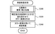
続いて、部品実装機10が部品実装処理を行った後に行う部品の実装検査について説明する。図9は、実装検査処理の一例を示すフローチャートである。実装検査処理では、制御部61は、部品が実装された基板Sの上方にマークカメラ50が来るようにヘッド移動装置30を制御して合成元となる元画像の撮像・補正処理を実行する(S300)。図10は、元画像の撮像・補正処理の一例を示すフローチャートである。Next, the component mounting inspection performed after the
元画像の撮像・補正処理では、マークカメラ50の制御部57は、まず、赤光源(赤色LED52aや赤色LED54a)の照明下で基板Sをマークカメラ50で撮像して元画像(単色画像)R1を取得する(S302)。そして、画像処理部58は、記憶部59に記憶された補正量ΔRSを用いて元画像R1を補正して制御部61に出力する(S304)。次に、制御部57は、緑光源(緑色LED52bや緑色LED54b)の照明下で基板Sをマークカメラ50で撮像して元画像G1を取得する(S306)。そして、画像処理部58は、記憶部59に記憶された補正量ΔGSを用いて元画像G1を補正して制御部61に出力する(S308)。続いて、制御部57は、青光源(青色LED52cや青色LED54c)の照明下で基板Sをマークカメラ50で撮像して元画像B1を取得する(S310)。そして、画像処理部58は、記憶部59に記憶された青光源の補正量ΔBSを用いて元画像B1を補正して制御部61に出力する(S312)。各光源色の補正量ΔRS,ΔGS,ΔBSをそれぞれ用いて各元画像R1,G1,B1を補正することにより、歪曲収差と色収差とをまとめて補正することができる。ここで、補正量設定処理において、緑基準画像G0や青基準画像B0のそれぞれで赤基準画像R0と同様の処理を行って歪曲収差の補正量と色収差の補正量とを光源色毎に設定した場合、歪曲収差の補正と色収差の補正とを別々に行うことになり補正に手間と時間がかかる。本実施形態では、歪曲収差と色収差とをまとめて補正することができるから、補正時間の短縮が可能となり、カラー画像を速やかに合成処理して実装検査を行うことができる。In the image capture / correction process of the original image, the
画像処理部62は、こうして生成された補正後の各元画像R1,G1,B1を取得すると、各元画像R1,G1,B1を重ね合わせて合成処理することによりカラー画像を生成する(S320)。そして、画像処理部62は、生成したカラー画像を用いて実装検査を行って(S340)、実装検査処理を終了する。画像処理部62は、実装検査では、カラー画像から認識した部品の位置が当該部品の実装位置であるか否かを検査したり、部品の実装ずれ量(位置ずれ量や回転ずれ量)が許容範囲内であるか否かを検査したりする。上述した補正量ΔRS,ΔGS,ΔBSを用いて各元画像R1,G1,B1の歪曲収差と色収差とが適切に補正されているから、合成したカラー画像における重ね合わせのずれを抑えることができる。このため、重ね合わせのずれによる部品の位置の誤認識などを抑えることができるから、実装検査の検査精度を向上させることができる。When the
ここで、本実施形態の構成要素と本開示の構成要素との対応関係を明らかにする。本実施形態の記憶部59が記憶部に相当し、落射光源52と側射光源54とを備える照明部50aが光源部に相当し、モノクロCCD56を備えるカメラ本体部50bが撮像部に相当し、画像処理部58が補正部に相当し、制御部61が検査部に相当する。また、マークカメラ50が撮像装置に相当する。マークカメラ50と制御装置60とが検査装置に相当する。なお、本実施形態では、撮像装置や検査装置の動作を説明することにより本開示の画像補正方法の一例も明らかにしている。Here, the correspondence between the components of the present embodiment and the components of the present disclosure will be clarified. The
以上説明した部品実装機10では、マークカメラ50の記憶部59に、R,G,Bの各補正量ΔRS,ΔGS,ΔBSが記憶されている。補正量ΔRSは、ジグプレートJPを赤光源の照明下で撮像した赤基準画像(特定の光源色の基準画像)R0から認識した基準マークMの位置を、赤基準画像R0における基準位置RMPに補正する補正量として設定される。一方、補正量ΔGS,ΔBSは、ジグプレートJPを緑光源,青光源の照明下で撮像した緑基準画像G0,青基準画像B0から認識した基準マークMの位置を、赤基準画像R0における基準位置RMPに補正する補正量としてそれぞれ設定される。そして、部品が実装された基板Sの元画像R1,G1,B1を撮像し、補正量ΔRS,ΔGS,ΔBSをそれぞれ用いて各元画像R1,G1,B1の歪曲収差と色収差とをまとめて補正する。このため、歪曲収差と色収差のそれぞれの補正量を用いて別々に補正する場合に比べて、元画像R1,G1,B1の歪曲収差と色収差との補正の手間を軽減することができる。In the
また、補正量ΔRSの設定では、赤基準画像R0におけるジグプレートJPの中心位置JPcと基準マークMの位置とに基づいてジグプレートJPの傾きを演算し、その傾きと基準マークMの理想位置とを用いて基準位置RMPが定められる。このため、ジグプレートJPの傾きを反映させた基準位置RMPを適切に定めて、補正量ΔRSを求めることができる。また、他の補正量ΔGS,ΔBSの設定では、ジグプレートJPの中心位置JPcや傾きを求めることなく基準マークMの位置を求めればよいから、各補正量を速やかに設定することができる。Further, in the setting of the correction amount ΔRS, the inclination of the jig plate JP is calculated based on the center position JPc of the jig plate JP and the position of the reference mark M in the red reference image R0, and the inclination and the ideal position of the reference mark M are calculated. The reference position RMP is determined using. Therefore, the reference position RMP that reflects the inclination of the jig plate JP can be appropriately determined, and the correction amount ΔRS can be obtained. Further, in the setting of other correction amounts ΔGS and ΔBS, the position of the reference mark M may be obtained without obtaining the center position JPc and the inclination of the jig plate JP, so that each correction amount can be set quickly.
また、部品実装機10では、補正後の元画像R1,G1,B1を重ね合わせてカラー画像を生成し、カラー画像を用いて部品の実装検査を行うから、歪曲収差と色収差を抑えたずれの少ないカラー画像に基づいて部品の実装検査を精度よく行うことができる。Further, in the
なお、本開示は上述した実施形態に何ら限定されることはなく、本開示の技術的範囲に属する限り種々の態様で実施し得ることはいうまでもない。It is needless to say that the present disclosure is not limited to the above-described embodiment, and can be implemented in various aspects as long as it belongs to the technical scope of the present disclosure.
例えば、上述した実施形態では、赤光源の補正量ΔRSを設定する際に用いた基準位置RMPを、緑光源の補正量ΔGSや青画像の補正量ΔBSを設定する際に用いた。即ち、特定の光源色の基準画像として赤基準画像R0を用いたが、これに限られず、特定の光源色の基準画像として緑基準画像G0を用いてもよいし、青基準画像B0を用いてもよい。For example, in the above-described embodiment, the reference position RMP used when setting the correction amount ΔRS of the red light source is used when setting the correction amount ΔGS of the green light source and the correction amount ΔBS of the blue image. That is, the red reference image R0 is used as the reference image of the specific light source color, but the present invention is not limited to this, and the green reference image G0 may be used as the reference image of the specific light source color, or the blue reference image B0 is used. May be good.
上述した実施形態では、各基準マークMの位置を各基準マークMの基準位置RMPに位置合わせするための補正量ΔRS,ΔGS,ΔBSを、基準マークM毎にそれぞれ演算し記憶部59に記憶させたが、これに限られるものではない。各色の基準画像の各基準マークMの補正量ΔRS,ΔGS,ΔBSを演算した後に、各色の基準画像におけるさらに細かいピッチの位置座標毎の補正量を、隣接する基準マークMの補正量を用いて補間演算し、記憶部59に記憶させてもよい。各色の基準画像において、演算された位置座標毎の補正量を用いてさらに補間演算し、最終的にピクセル毎の補正量を演算し、記憶部59に記憶させてもよい。In the above-described embodiment, the correction amounts ΔRS, ΔGS, and ΔBS for aligning the position of each reference mark M with the reference position RMP of each reference mark M are calculated for each reference mark M and stored in the
上述した実施形態では、マークカメラ50の画像処理部58が補正量ΔRS,ΔGS,ΔBSをそれぞれ用いて元画像R1,G1,B1を補正したが、これに限られず、制御装置60の制御部61が補正を行うものとしてもよい。そのようにする場合、マークカメラ50の記憶部59が補正量ΔRS,ΔGS,ΔBSを記憶していてもよく、制御装置60の記憶部63が補正量ΔRS,ΔGS,ΔBSを記憶していてもよい。In the above-described embodiment, the
上述した実施形態では、R,G,Bの3色の元画像R1,G1,B1を合成するものを例示したが、これに限られず、これらの3色のうちいずれか2色以上または他の色を含む2色以上の元画像を合成するものであればよい。2色の場合でも一方を特定の光源色として補正量を設定すればよい。In the above-described embodiment, the one in which the original images R1, G1, and B1 of the three colors R, G, and B are combined has been illustrated, but the present invention is not limited to this, and any two or more of these three colors or the other It suffices as long as it synthesizes the original images of two or more colors including colors. Even in the case of two colors, the correction amount may be set with one of them as a specific light source color.
上述した実施形態では、部品が実装された基板Sの検査を行うためのカラー画像を生成するものを例示したが、これに限られるものではない。検査対象となる基板Sや部品の色、素材、形状などによっては、画像処理部62は、カラー画像でなくても、いずれかの元画像(単色画像)R1,G1,B1のままで実装検査を行うことができる場合もある。このように実装検査においてカラー画像を用いない場合であっても、画像処理部62は、各元画像を合成処理することによりカラー画像を生成し、制御部61は、生成されたカラー画像を、部品実装機10の図示しない表示装置に表示してもよい。表示装置にカラー画像が表示されることにより、作業者は、検査対象の状況を容易に認識することができる。In the above-described embodiment, a color image for inspecting the substrate S on which the component is mounted has been illustrated, but the present invention is not limited to this. Depending on the color, material, shape, etc. of the substrate S and parts to be inspected, the
上述した実施形態では、マークカメラ50が、R,G,Bの3色の光源(LED52a~52c,54a~54c)を有する照明部50aと、モノクロCCD56を有するカメラ本体部50bとを一体的に備えるものとしたが、これに限られるものではない。例えば、照明部50aと、カメラ本体部50bとが、別々に構成されていてもよい。In the above-described embodiment, the
上述した実施形態では、部品実装機10が検査装置を兼ねるものとしたが、これに限られず、生産ラインにおける部品実装機10よりも基板搬送方向における下流側に専用の検査装置を備えてもよい。In the above-described embodiment, the
上述した実施形態では、部品が実装された基板の検査を行うためのカラー画像を生成するものを例示したが、これに限られるものではない。部品が実装される前に基板Sの半田の検査を行うためのカラー画像を生成してもよいし、フィーダ20により供給された部品の認識を行うためのカラー画像を生成してもよい。また、マークカメラ50に適用するものを例示したが、パーツカメラ23など他の撮像装置に適用してもよい。また、部品の実装に関する検査に限られず、各色の元画像を合成した合成画像を用いて検査を行うものに適用してもよい。また、1または複数のコンピュータが本開示の画像補正方法を行うものであってもよく、例えば汎用のコンピュータとして構成された画像処理装置が本開示の画像補正方法を行ってもよい。In the above-described embodiment, an example is used for generating a color image for inspecting a substrate on which a component is mounted, but the present invention is not limited to this. A color image for inspecting the solder of the substrate S may be generated before the parts are mounted, or a color image for recognizing the parts supplied by the
ここで、本開示の画像補正方法は、以下のようにしてもよい。例えば本開示の画像補正方法において、前記ステップ(a)では、前記特定の光源色の基準画像における前記部材の中心位置と前記基準マークの位置とを認識し、前記中心位置と前記基準マークの位置とに基づいて前記部材の傾きを導出し、前記部材の傾きと前記基準マークの理想位置とを用いて前記特定の光源色の基準画像における前記基準位置を定めて、前記補正量を求め、前記ステップ(b)では、前記他の光源色の前記基準画像毎に前記基準マークの位置を認識して、前記補正量を求めるものとしてもよい。こうすれば、基準マークが設けられた部材の傾きを基準マークの理想位置に反映させて特定の光源色の基準画像における基準マークの基準位置を適切に定めて、補正量を求めることができる。また、他の光源色の補正量を求める際に、他の光源色の基準画像毎に基準マークの位置を認識すればよく部材の中心位置などの認識を必要としないから、補正量を速やかに求めることができる。Here, the image correction method of the present disclosure may be as follows. For example, in the image correction method of the present disclosure, in the step (a), the center position of the member and the position of the reference mark in the reference image of the specific light source color are recognized, and the center position and the position of the reference mark are recognized. Based on the above, the inclination of the member is derived, the reference position in the reference image of the specific light source color is determined using the inclination of the member and the ideal position of the reference mark, and the correction amount is obtained. In step (b), the position of the reference mark may be recognized for each of the reference images of the other light source colors to obtain the correction amount. In this way, the inclination of the member provided with the reference mark is reflected in the ideal position of the reference mark, the reference position of the reference mark in the reference image of the specific light source color is appropriately determined, and the correction amount can be obtained. Further, when obtaining the correction amount of another light source color, it is sufficient to recognize the position of the reference mark for each reference image of the other light source color, and it is not necessary to recognize the center position of the member. You can ask.
本開示の撮像装置は、上述したいずれかの画像補正方法で設定された前記補正量を各光源色に対応付けて記憶する記憶部と、複数の異なる光源色を照射可能な光源部と、各光源色のそれぞれの照明下で合成画像の元画像を撮像する撮像部と、前記元画像が撮像されると、各光源色に対応付けられた前記補正量を用いて各光源色の元画像の歪曲収差と色収差とをまとめて補正する補正部と、を備えることを要旨とする。The imaging apparatus of the present disclosure includes a storage unit that stores the correction amount set by any of the above-mentioned image correction methods in association with each light source color, a light source unit that can irradiate a plurality of different light source colors, and each. An imaging unit that captures the original image of the composite image under each illumination of the light source color, and when the original image is captured, the original image of each light source color is subjected to the correction amount associated with each light source color. The gist is to provide a correction unit that collectively corrects distortion and chromatic aberration.
本開示の撮像装置は、上述したいずれかの画像補正方法で設定された補正量を用いて各光源色の元画像の歪曲収差と色収差とをまとめて補正するから、上述した画像補正方法と同様に、元画像の歪曲収差と色収差との補正の手間を軽減して合成画像の速やかな生成を可能とすることができる。Since the image pickup apparatus of the present disclosure collectively corrects the distortion and chromatic aberration of the original image of each light source color by using the correction amount set by any of the above-mentioned image correction methods, it is the same as the above-mentioned image correction method. In addition, it is possible to reduce the trouble of correcting the distortion aberration and the chromatic aberration of the original image and enable the rapid generation of the composite image.
本開示の検査装置は、上述したいずれかの画像補正方法で設定された前記補正量を各光源色に対応付けて記憶する記憶部と、複数の異なる光源色を照射可能な光源部と、部品が実装された基板の画像を元画像として各光源色のそれぞれの照明下で撮像する撮像部と、前記元画像が撮像されると、各光源色に対応付けられた前記補正量を用いて各光源色の元画像の歪曲収差と色収差とをまとめて補正する補正部と、歪曲収差と色収差とが補正された前記元画像を重ね合わせて合成画像を生成し、前記合成画像に基づいて前記部品の実装検査を行う検査部と、を備えることを要旨とする。The inspection device of the present disclosure includes a storage unit that stores the correction amount set by any of the above-mentioned image correction methods in association with each light source color, a light source unit that can irradiate a plurality of different light source colors, and components. An imaging unit that captures an image of a substrate on which is mounted as an original image under the respective illuminations of each light source color, and when the original image is captured, each using the correction amount associated with each light source color. A correction unit that collectively corrects the distortion and chromatic aberration of the original image of the light source color and the original image that has been corrected for the distortion and chromatic aberration are superimposed to generate a composite image, and the component is based on the composite image. The gist is to have an inspection department that conducts mounting inspections.
本開示の検査装置は、上述したいずれかの画像補正方法で設定された補正量を用いて各光源色の元画像の歪曲収差と色収差とをまとめて補正するから、上述した画像補正方法と同様に、元画像の歪曲収差と色収差との補正の手間を軽減して合成画像の速やかな生成を可能とすることができる。また、合成画像に基づいて部品の実装検査を精度よく行うことができる。Since the inspection apparatus of the present disclosure collectively corrects the distortion and chromatic aberration of the original image of each light source color by using the correction amount set by any of the above-mentioned image correction methods, it is the same as the above-mentioned image correction method. In addition, it is possible to reduce the trouble of correcting the distortion aberration and the chromatic aberration of the original image and enable the rapid generation of the composite image. In addition, it is possible to accurately inspect the mounting of parts based on the composite image.
本開示は、撮像装置や検査装置、部品実装機の製造産業などに利用可能である。This disclosure can be used in the manufacturing industry of imaging devices, inspection devices, component mounting machines, and the like.
10 部品実装機、11 基台、12 筐体、20 フィーダ、21 リール、22 基板搬送装置、23 パーツカメラ、30 ヘッド移動装置、31 X軸ガイドレール、32 X軸スライダ、33 X軸アクチュエータ、35 Y軸ガイドレール、36 Y軸スライダ、37 Y軸アクチュエータ、40 ヘッド、41 Z軸アクチュエータ、42 θ軸アクチュエータ、45 吸着ノズル、50 マークカメラ、50a 照明部、50b カメラ本体部、51 ハウジング、52 落射光源、52a 赤色LED、52b 緑色LED、52c 青色LED、52d 支持板、53 ハーフミラー、54 側射光源、54a 赤色LED、54b 緑色LED、54c 青色LED、54d 支持板、55 拡散板、56 モノクロCCD、57 制御部、58 画像処理部、59 記憶部、60 制御装置、61 制御部、62 画像処理部、63 記憶部、S 基板。10 parts mounting machine, 11 base, 12 housing, 20 feeder, 21 reel, 22 board transfer device, 23 parts camera, 30 head moving device, 31 X-axis guide rail, 32 X-axis slider, 33 X-axis actuator, 35 Y-axis guide rail, 36 Y-axis slider, 37 Y-axis actuator, 40 head, 41 Z-axis actuator, 42 θ-axis actuator, 45 suction nozzle, 50 mark camera, 50a lighting unit, 50b camera body, 51 housing, 52 epi-illumination Light source, 52a red LED, 52b green LED, 52c blue LED, 52d support plate, 53 half mirror, 54 side emission light source, 54a red LED, 54b green LED, 54c blue LED, 54d support plate, 55 diffuser, 56 monochrome CCD , 57 control unit, 58 image processing unit, 59 storage unit, 60 control device, 61 control unit, 62 image processing unit, 63 storage unit, S board.
Claims (4)
Translated fromJapanese(a)基準マークが設けられた部材が各光源色のそれぞれの照明下で撮像された光源色毎の基準画像のうち、特定の光源色の基準画像から認識した前記基準マークの位置を、前記特定の光源色の基準画像における前記基準マークの基準位置に補正するための補正量を求めて、光源色に対応付けて設定するステップと、
(b)前記特定の光源色以外の他の光源色の前記基準画像から認識した前記基準マークの位置を、前記特定の光源色の基準画像における前記基準位置に補正するための補正量を他の光源色毎にそれぞれ求めて、光源色に対応付けて設定するステップと、
(c)前記元画像が撮像されると、各光源色に対応付けられた補正量を用いて各光源色の元画像の歪曲収差と色収差とをまとめて補正するステップと、
を含む画像補正方法。This is an image correction method for correcting the original image when a composite image is generated by superimposing a plurality of original images captured under the respective illuminations of a plurality of different light source colors.
(A) Among the reference images for each light source color captured by the member provided with the reference mark under the respective illumination of each light source color, the position of the reference mark recognized from the reference image of a specific light source color is determined. A step of obtaining a correction amount for correcting to the reference position of the reference mark in the reference image of a specific light source color and setting the correction amount in association with the light source color.
(B) Another correction amount for correcting the position of the reference mark recognized from the reference image of the light source color other than the specific light source color to the reference position in the reference image of the specific light source color. A step to obtain each light source color and set it in association with the light source color,
(C) When the original image is captured, a step of collectively correcting the distortion and chromatic aberration of the original image of each light source color by using the correction amount associated with each light source color, and
Image correction methods including.
前記ステップ(a)では、前記特定の光源色の基準画像における前記部材の中心位置と前記基準マークの位置とを認識し、前記中心位置と前記基準マークの位置とに基づいて前記部材の傾きを導出し、前記部材の傾きと前記基準マークの理想位置とを用いて前記特定の光源色の基準画像における前記基準位置を定めて、前記補正量を求め、
前記ステップ(b)では、前記他の光源色の前記基準画像毎に前記基準マークの位置を認識して、前記補正量を求める
画像補正方法。The image correction method according to claim 1.
In the step (a), the center position of the member and the position of the reference mark in the reference image of the specific light source color are recognized, and the inclination of the member is determined based on the center position and the position of the reference mark. Derived, the reference position in the reference image of the specific light source color is determined using the inclination of the member and the ideal position of the reference mark, and the correction amount is obtained.
In the step (b), an image correction method of recognizing the position of the reference mark for each of the reference images of the other light source colors and obtaining the correction amount.
複数の異なる光源色を照射可能な光源部と、
各光源色のそれぞれの照明下で合成画像の元画像を撮像する撮像部と、
前記元画像が撮像されると、各光源色に対応付けられた前記補正量を用いて各光源色の元画像の歪曲収差と色収差とをまとめて補正する補正部と、
を備える撮像装置。A storage unit that stores the correction amount set by the image correction method of claim 1 or 2 in association with each light source color, and a storage unit.
A light source unit that can irradiate multiple different light source colors,
An imaging unit that captures the original image of the composite image under the respective illumination of each light source color,
When the original image is captured, a correction unit that collectively corrects the distortion and chromatic aberration of the original image of each light source color by using the correction amount associated with each light source color.
An imaging device comprising.
複数の異なる光源色を照射可能な光源部と、
部品が実装された基板の画像を元画像として各光源色のそれぞれの照明下で撮像する撮像部と、
前記元画像が撮像されると、各光源色に対応付けられた前記補正量を用いて各光源色の元画像の歪曲収差と色収差とをまとめて補正する補正部と、
歪曲収差と色収差とが補正された前記元画像を重ね合わせて合成画像を生成し、前記合成画像に基づいて前記部品の実装検査を行う検査部と、
を備える検査装置。A storage unit that stores the correction amount set by the image correction method of claim 1 or 2 in association with each light source color, and a storage unit.
A light source unit that can irradiate multiple different light source colors,
An image pickup unit that captures an image of the board on which the components are mounted as the original image under the respective illumination of each light source color,
When the original image is captured, a correction unit that collectively corrects the distortion and chromatic aberration of the original image of each light source color by using the correction amount associated with each light source color.
An inspection unit that superimposes the original image corrected for distortion and chromatic aberration to generate a composite image, and performs a mounting inspection of the component based on the composite image.
Inspection device equipped with.
Priority Applications (5)
| Application Number | Priority Date | Filing Date | Title |
|---|---|---|---|
| EP20920858.6AEP4113967A4 (en) | 2020-02-27 | 2020-02-27 | IMAGE CORRECTION DEVICE, IMAGING DEVICE AND INSPECTION DEVICE |
| PCT/JP2020/008044WO2021171487A1 (en) | 2020-02-27 | 2020-02-27 | Image correction method, imaging device, and inspection device |
| CN202080097030.2ACN115136579B (en) | 2020-02-27 | 2020-02-27 | Image correction method, imaging device and inspection device |
| JP2022502718AJP7365487B2 (en) | 2020-02-27 | 2020-02-27 | Image correction method, imaging device and inspection device |
| US17/904,815US11997375B2 (en) | 2020-02-27 | 2020-02-27 | Image correction method, imaging device, and inspection device |
Applications Claiming Priority (1)
| Application Number | Priority Date | Filing Date | Title |
|---|---|---|---|
| PCT/JP2020/008044WO2021171487A1 (en) | 2020-02-27 | 2020-02-27 | Image correction method, imaging device, and inspection device |
Publications (1)
| Publication Number | Publication Date |
|---|---|
| WO2021171487A1true WO2021171487A1 (en) | 2021-09-02 |
Family
ID=77491096
Family Applications (1)
| Application Number | Title | Priority Date | Filing Date |
|---|---|---|---|
| PCT/JP2020/008044CeasedWO2021171487A1 (en) | 2020-02-27 | 2020-02-27 | Image correction method, imaging device, and inspection device |
Country Status (5)
| Country | Link |
|---|---|
| US (1) | US11997375B2 (en) |
| EP (1) | EP4113967A4 (en) |
| JP (1) | JP7365487B2 (en) |
| CN (1) | CN115136579B (en) |
| WO (1) | WO2021171487A1 (en) |
Families Citing this family (1)
| Publication number | Priority date | Publication date | Assignee | Title |
|---|---|---|---|---|
| CN116075148B (en)* | 2023-03-14 | 2023-06-20 | 四川易景智能终端有限公司 | PCBA board production line intelligent supervision system based on artificial intelligence |
Citations (5)
| Publication number | Priority date | Publication date | Assignee | Title |
|---|---|---|---|---|
| JPH08116490A (en)* | 1994-10-14 | 1996-05-07 | Olympus Optical Co Ltd | Image processing unit |
| JP2014035261A (en)* | 2012-08-08 | 2014-02-24 | Sony Corp | Information processing method, information processor, program, imaging apparatus, inspection method, inspection device, and method of manufacturing substrate |
| JP2015032895A (en)* | 2013-07-31 | 2015-02-16 | ブラザー工業株式会社 | Image processing apparatus |
| WO2016013470A1 (en)* | 2014-07-22 | 2016-01-28 | オリンパス株式会社 | Image processing device, image processing method, image processing program, and image-capturing system |
| WO2019111331A1 (en) | 2017-12-05 | 2019-06-13 | 株式会社Fuji | Imaging unit and component mounting machine |
Family Cites Families (14)
| Publication number | Priority date | Publication date | Assignee | Title |
|---|---|---|---|---|
| JP3549413B2 (en)* | 1997-12-04 | 2004-08-04 | 富士写真フイルム株式会社 | Image processing method and image processing apparatus |
| US6682863B2 (en)* | 2002-06-27 | 2004-01-27 | Eastman Kodak Company | Depositing an emissive layer for use in an organic light-emitting display device (OLED) |
| US7698068B2 (en)* | 2004-06-17 | 2010-04-13 | Cadent Ltd. | Method for providing data associated with the intraoral cavity |
| JP5109352B2 (en)* | 2006-12-06 | 2012-12-26 | ソニー株式会社 | Projector and projector adjustment method |
| JP5353361B2 (en)* | 2009-03-26 | 2013-11-27 | ブラザー工業株式会社 | Color image display device |
| JP2011215395A (en)* | 2010-03-31 | 2011-10-27 | Canon Inc | Image pickup apparatus having aberration correcting function and aberration correcting method for image pickup apparatus |
| JP2012138891A (en)* | 2010-12-08 | 2012-07-19 | Canon Inc | Imaging apparatus |
| JP2013017142A (en)* | 2011-07-06 | 2013-01-24 | Sony Corp | Image processing apparatus, imaging apparatus, image processing method, and program |
| JP5762587B2 (en)* | 2013-04-15 | 2015-08-12 | キヤノン株式会社 | Image processing apparatus and image processing method |
| JP6333250B2 (en)* | 2013-07-08 | 2018-05-30 | 株式会社Fuji | Component holding state detection method and component mounting apparatus |
| DE102014112666A1 (en)* | 2014-08-29 | 2016-03-03 | Carl Zeiss Ag | Image pickup device and method for image acquisition |
| US10953813B2 (en)* | 2015-12-21 | 2021-03-23 | Koito Manufacturing Co., Ltd. | Image acquisition device to be used by vehicle and vehicle provided with same |
| CN105915757B (en)* | 2016-06-06 | 2018-06-01 | 北京时代拓灵科技有限公司 | A kind of color calibration method based on RGB color channel error function |
| US11350063B2 (en)* | 2020-04-14 | 2022-05-31 | Apple Inc. | Circuit for correcting lateral chromatic abberation |
- 2020
- 2020-02-27USUS17/904,815patent/US11997375B2/enactiveActive
- 2020-02-27JPJP2022502718Apatent/JP7365487B2/enactiveActive
- 2020-02-27WOPCT/JP2020/008044patent/WO2021171487A1/ennot_activeCeased
- 2020-02-27EPEP20920858.6Apatent/EP4113967A4/enactivePending
- 2020-02-27CNCN202080097030.2Apatent/CN115136579B/enactiveActive
Patent Citations (5)
| Publication number | Priority date | Publication date | Assignee | Title |
|---|---|---|---|---|
| JPH08116490A (en)* | 1994-10-14 | 1996-05-07 | Olympus Optical Co Ltd | Image processing unit |
| JP2014035261A (en)* | 2012-08-08 | 2014-02-24 | Sony Corp | Information processing method, information processor, program, imaging apparatus, inspection method, inspection device, and method of manufacturing substrate |
| JP2015032895A (en)* | 2013-07-31 | 2015-02-16 | ブラザー工業株式会社 | Image processing apparatus |
| WO2016013470A1 (en)* | 2014-07-22 | 2016-01-28 | オリンパス株式会社 | Image processing device, image processing method, image processing program, and image-capturing system |
| WO2019111331A1 (en) | 2017-12-05 | 2019-06-13 | 株式会社Fuji | Imaging unit and component mounting machine |
Also Published As
| Publication number | Publication date |
|---|---|
| JPWO2021171487A1 (en) | 2021-09-02 |
| US11997375B2 (en) | 2024-05-28 |
| EP4113967A4 (en) | 2023-03-29 |
| US20230116070A1 (en) | 2023-04-13 |
| CN115136579A (en) | 2022-09-30 |
| CN115136579B (en) | 2023-08-04 |
| EP4113967A1 (en) | 2023-01-04 |
| JP7365487B2 (en) | 2023-10-19 |
Similar Documents
| Publication | Publication Date | Title |
|---|---|---|
| JP5877639B2 (en) | Image generating apparatus and image generating method | |
| KR101390890B1 (en) | Mounting device and mounting method for the semiconductor chip | |
| JP7705995B2 (en) | Substrate work system | |
| JP2015162519A (en) | Electronic component mounting apparatus and electronic component mounting method | |
| JP7301973B2 (en) | inspection equipment | |
| US11095800B2 (en) | Imaging unit and component mounting machine | |
| JP2013021196A (en) | Image processing apparatus of component mounting machine | |
| JP7365487B2 (en) | Image correction method, imaging device and inspection device | |
| JP6836938B2 (en) | Manufacturing method of die bonding equipment and semiconductor equipment | |
| JP7562860B2 (en) | Component Mounting Machine | |
| JP7271738B2 (en) | Imaging unit | |
| US11557109B2 (en) | Image-capturing unit and component-mounting device | |
| WO2024241439A1 (en) | Image display system and image display method | |
| JP2009085689A (en) | 3D measuring device for electronic parts | |
| WO2024189728A1 (en) | Inspection device and inspection system | |
| WO2018100692A1 (en) | Image processing method and image processing device for electronic part | |
| JP2006086432A (en) | Method and apparatus of creating inspecting data of packaging substrate |
Legal Events
| Date | Code | Title | Description |
|---|---|---|---|
| 121 | Ep: the epo has been informed by wipo that ep was designated in this application | Ref document number:20920858 Country of ref document:EP Kind code of ref document:A1 | |
| ENP | Entry into the national phase | Ref document number:2022502718 Country of ref document:JP Kind code of ref document:A | |
| NENP | Non-entry into the national phase | Ref country code:DE | |
| ENP | Entry into the national phase | Ref document number:2020920858 Country of ref document:EP Effective date:20220927 |