WO2021157031A1 - Setting change device, setting change method, and setting change program - Google Patents
Setting change device, setting change method, and setting change programDownload PDFInfo
- Publication number
- WO2021157031A1 WO2021157031A1PCT/JP2020/004637JP2020004637WWO2021157031A1WO 2021157031 A1WO2021157031 A1WO 2021157031A1JP 2020004637 WJP2020004637 WJP 2020004637WWO 2021157031 A1WO2021157031 A1WO 2021157031A1
- Authority
- WO
- WIPO (PCT)
- Prior art keywords
- log
- item
- factor
- factor candidate
- setting change
- Prior art date
- Legal status (The legal status is an assumption and is not a legal conclusion. Google has not performed a legal analysis and makes no representation as to the accuracy of the status listed.)
- Ceased
Links
Images


Classifications
- G—PHYSICS
- G06—COMPUTING OR CALCULATING; COUNTING
- G06F—ELECTRIC DIGITAL DATA PROCESSING
- G06F11/00—Error detection; Error correction; Monitoring
- G06F11/30—Monitoring
- G06F11/34—Recording or statistical evaluation of computer activity, e.g. of down time, of input/output operation ; Recording or statistical evaluation of user activity, e.g. usability assessment
- G—PHYSICS
- G06—COMPUTING OR CALCULATING; COUNTING
- G06F—ELECTRIC DIGITAL DATA PROCESSING
- G06F9/00—Arrangements for program control, e.g. control units
- G06F9/06—Arrangements for program control, e.g. control units using stored programs, i.e. using an internal store of processing equipment to receive or retain programs
- G06F9/44—Arrangements for executing specific programs
- G06F9/455—Emulation; Interpretation; Software simulation, e.g. virtualisation or emulation of application or operating system execution engines
- G06F9/45533—Hypervisors; Virtual machine monitors
- G06F9/45541—Bare-metal, i.e. hypervisor runs directly on hardware
- G—PHYSICS
- G06—COMPUTING OR CALCULATING; COUNTING
- G06F—ELECTRIC DIGITAL DATA PROCESSING
- G06F11/00—Error detection; Error correction; Monitoring
- G06F11/07—Responding to the occurrence of a fault, e.g. fault tolerance
- G—PHYSICS
- G06—COMPUTING OR CALCULATING; COUNTING
- G06F—ELECTRIC DIGITAL DATA PROCESSING
- G06F11/00—Error detection; Error correction; Monitoring
- G06F11/07—Responding to the occurrence of a fault, e.g. fault tolerance
- G06F11/0703—Error or fault processing not based on redundancy, i.e. by taking additional measures to deal with the error or fault not making use of redundancy in operation, in hardware, or in data representation
- G06F11/0793—Remedial or corrective actions
- G—PHYSICS
- G06—COMPUTING OR CALCULATING; COUNTING
- G06F—ELECTRIC DIGITAL DATA PROCESSING
- G06F9/00—Arrangements for program control, e.g. control units
- G06F9/06—Arrangements for program control, e.g. control units using stored programs, i.e. using an internal store of processing equipment to receive or retain programs
- G06F9/44—Arrangements for executing specific programs
- G06F9/455—Emulation; Interpretation; Software simulation, e.g. virtualisation or emulation of application or operating system execution engines
- G06F9/45533—Hypervisors; Virtual machine monitors
- G06F9/45554—Instruction set architectures of guest OS and hypervisor or native processor differ, e.g. Bochs or VirtualPC on PowerPC MacOS
- G—PHYSICS
- G06—COMPUTING OR CALCULATING; COUNTING
- G06F—ELECTRIC DIGITAL DATA PROCESSING
- G06F9/00—Arrangements for program control, e.g. control units
- G06F9/06—Arrangements for program control, e.g. control units using stored programs, i.e. using an internal store of processing equipment to receive or retain programs
- G06F9/44—Arrangements for executing specific programs
- G06F9/455—Emulation; Interpretation; Software simulation, e.g. virtualisation or emulation of application or operating system execution engines
- G06F9/45533—Hypervisors; Virtual machine monitors
- G06F9/45558—Hypervisor-specific management and integration aspects
- G—PHYSICS
- G06—COMPUTING OR CALCULATING; COUNTING
- G06F—ELECTRIC DIGITAL DATA PROCESSING
- G06F9/00—Arrangements for program control, e.g. control units
- G06F9/06—Arrangements for program control, e.g. control units using stored programs, i.e. using an internal store of processing equipment to receive or retain programs
- G06F9/46—Multiprogramming arrangements
- G06F9/50—Allocation of resources, e.g. of the central processing unit [CPU]
- G06F9/5061—Partitioning or combining of resources
- G06F9/5077—Logical partitioning of resources; Management or configuration of virtualized resources
- G—PHYSICS
- G06—COMPUTING OR CALCULATING; COUNTING
- G06F—ELECTRIC DIGITAL DATA PROCESSING
- G06F9/00—Arrangements for program control, e.g. control units
- G06F9/06—Arrangements for program control, e.g. control units using stored programs, i.e. using an internal store of processing equipment to receive or retain programs
- G06F9/44—Arrangements for executing specific programs
- G06F9/455—Emulation; Interpretation; Software simulation, e.g. virtualisation or emulation of application or operating system execution engines
- G06F9/45533—Hypervisors; Virtual machine monitors
- G06F9/45558—Hypervisor-specific management and integration aspects
- G06F2009/45562—Creating, deleting, cloning virtual machine instances
- G—PHYSICS
- G06—COMPUTING OR CALCULATING; COUNTING
- G06F—ELECTRIC DIGITAL DATA PROCESSING
- G06F9/00—Arrangements for program control, e.g. control units
- G06F9/06—Arrangements for program control, e.g. control units using stored programs, i.e. using an internal store of processing equipment to receive or retain programs
- G06F9/44—Arrangements for executing specific programs
- G06F9/455—Emulation; Interpretation; Software simulation, e.g. virtualisation or emulation of application or operating system execution engines
- G06F9/45533—Hypervisors; Virtual machine monitors
- G06F9/45558—Hypervisor-specific management and integration aspects
- G06F2009/4557—Distribution of virtual machine instances; Migration and load balancing
- G—PHYSICS
- G06—COMPUTING OR CALCULATING; COUNTING
- G06F—ELECTRIC DIGITAL DATA PROCESSING
- G06F9/00—Arrangements for program control, e.g. control units
- G06F9/06—Arrangements for program control, e.g. control units using stored programs, i.e. using an internal store of processing equipment to receive or retain programs
- G06F9/44—Arrangements for executing specific programs
- G06F9/455—Emulation; Interpretation; Software simulation, e.g. virtualisation or emulation of application or operating system execution engines
- G06F9/45533—Hypervisors; Virtual machine monitors
- G06F9/45558—Hypervisor-specific management and integration aspects
- G06F2009/45591—Monitoring or debugging support
Definitions
- This disclosurerelates to a guest OS (Operating System) setting technology that operates on a hypervisor.
- a hypervisoris used to use an RTOS (Real Time Operating System) which is a control system OS (Operating System) and GPOS (General) which is an information system OS. Purpose Operating System) is operated at the same time.
- the hypervisorallocates hardware such as a CPU (Central Processing Unit), a memory, and an I / O (Input / Output) device to each guest OS.
- the guest OSis an RTOS and a GPOS in the case of the above-mentioned embedded device.
- Patent Document 1describes a technique for automatically allocating hardware to each guest OS.
- the amount of hardware resources required for each guest OSis determined by checking the load status such as the CPU load and the memory load in each guest OS, and the hardware resources are allocated to each guest OS. There is.
- the RTOSis required to be real-time.
- the guest OS that requires real-time performancemay operate on the hypervisor.
- only the items linked to the hardwaresuch as the CPU usage rate linked to the CPU and the memory usage linked to the memory are confirmed as the load status of the guest OS. .. Therefore, in the technique described in Patent Document 1, the real-time property of the guest OS may be impaired.
- An object of the present disclosureis to make it possible to realize an appropriate setting of a hypervisor in consideration of the real-time property of a guest OS.
- the setting change deviceis It is an operation log of an information processing device in which a guest OS (Operating System) operates on a hypervisor, and is a monitoring target log of a monitored item and a plurality of factor candidate items affecting the monitored item.
- a log acquisition unitthat acquires operation logs including factor candidate logs, and The value indicated by the factor candidate log in the normal state when the value indicated by the monitored log acquired by the log acquisition unit is within the reference range and the value indicated by the monitored log acquired by the log acquisition unit are within the reference range.
- a factor identification unitthat identifies factor candidate items whose difference from the value shown in the factor candidate log at the time of an abnormality, which is an outside case, exceeds the threshold value, and It is provided with a setting change unit that determines a setting item assigned to a factor candidate item specified by the factor identification unit as an item to be changed.
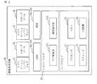
- FIG. The block diagram of the setting change system 1which concerns on Embodiment 1.
- FIG. The block diagram of the setting change apparatus 10which concerns on Embodiment 1.
- FIG. The block diagram of the information processing apparatus 20which concerns on Embodiment 1.
- FIG. The explanatory view of the monitoring target table 131which concerns on Embodiment 1.
- FIG. The explanatory view of the factor candidate table 132which concerns on Embodiment 1.
- FIG.The explanatory view of the result table 133 which concerns on Embodiment 1.
- FIG. The flowchartwhich shows the overall operation of the setting change system 1 which concerns on Embodiment 1.
- FIG. The flowchart of the setting change processingwhich concerns on Embodiment 1.
- the block diagram of the setting change apparatus 10which concerns on modification 2.
- FIG. The flowchart of the item determination processwhich concerns on Embodiment 2.
- the setting change system 1includes a setting change device 10 and an information processing device 20.
- the setting change device 10 and the information processing device 20are connected to each other via a transmission line 30.
- the setting change device 10is a computer that sets the hypervisor that operates in the information processing device 20.
- the information processing device 20is a computer on which a hypervisor operates and a plurality of guest operating systems operate on the hypervisor.
- the configuration of the setting changing device 10 according to the first embodimentwill be described with reference to FIG.
- the setting change device 10includes hardware of a processor 11, a memory 12, a storage 13, and an I / O device 14.
- the processor 11is connected to other hardware via a signal line and controls these other hardware.
- the setting change device 10includes a log acquisition unit 111, a factor identification unit 112, and a setting change unit 113 as functional components.
- the functions of each functional component of the setting changing device 10are realized by software.
- the storage 13stores a program that realizes the functions of each functional component of the setting changing device 10. This program is read into the memory 12 by the processor 11 and executed by the processor 11. As a result, the functions of each functional component of the setting changing device 10 are realized.
- the storage 13stores the monitoring target table 131, the factor candidate table 132, and the result table 133.
- the configuration of the information processing apparatus 20 according to the first embodimentwill be described with reference to FIG.
- the information processing device 20includes hardware of a processor 21, a memory 22, a storage 23, and an I / O device 24.
- the hypervisor 25operates on the hardware, and the guest OSs 26, GPOS261 and RTOS262, operate on the hypervisor 25.
- one or more application software 27 and a logging tool 28operate.
- GPOS261is an OS that performs information system processing
- RTOS262is an OS that performs control system processing.
- the application software 27is software that operates during actual operation of the information processing device 20.
- the logging tool 28is a tool for acquiring a log indicating the state of the OS and the application.
- the application software 27is software that is normally provided as the information processing device 20, and does not have a function related to hypervisor setting. Therefore, even when the information processing apparatus 20 does not include the application software 27, it is possible to set the hypervisor described below.
- the information processing device 20includes a log collecting unit 251 and a setting application unit 252 as functional components.
- the log collection unit 251 and the setting application unit 252are shown as functions of the hypervisor 25.
- the log collection unit 251 and the setting application unit 252are not limited to this, and may be realized as application software or the like on the guest OS 26, which is different from the GPOS 261 and RTOS 262 operating on the hypervisor 25.
- Processors 11 and 21are ICs (Integrated Circuits) that perform processing. Specific examples of the processors 11 and 21 are a CPU (Central Processing Unit), a DSP (Digital Signal Processor), and a GPU (Graphics Processing Unit).
- CPUCentral Processing Unit
- DSPDigital Signal Processor
- GPUGraphics Processing Unit
- the memories 12 and 22are storage devices that temporarily store data. Specific examples of the memories 12 and 22 are SRAM (Static Random Access Memory) and DRAM (Dynamic Random Access Memory).
- Storages 13 and 23are storage devices for storing data. Specific examples of the storages 13 and 23 are HDDs (Hard Disk Drives).
- the storages 13 and 23include SD (registered trademark, Secure Digital) memory card, CF (CompactFlash, registered trademark), NAND flash, flexible disk, optical disk, compact disk, Blu-ray (registered trademark) disk, and DVD (Digital Versaille Disk). ) May be a portable recording medium.
- the I / O devices 14 and 24are interfaces for connecting a device such as a display and a network controller. Specific examples of the I / O devices 14 and 24 are Ethernet (registered trademark), USB (Universal Serial Bus), and HDMI (registered trademark, High-Definition Multimedia Interface) ports.
- the operation of the setting change system 1 according to the first embodimentwill be described with reference to FIGS. 4 to 8.
- the operation procedure of the setting changing device 10 according to the first embodimentcorresponds to the setting changing method according to the first embodiment.
- the program that realizes the operation of the setting change device 10 according to the first embodimentcorresponds to the setting change program according to the first embodiment.
- the setting change device 10changes the setting of the hypervisor 25 based on the operation log of each guest OS 26 operating in the information processing device 20.
- the operation logincludes a monitoring target log and a factor candidate log.
- the monitoring target logis a log of monitoring target items related to performance or function that the information processing apparatus 20 must guarantee.
- the monitoring target logis a log for monitoring target items that affect the real-time performance of the guest OS 26.
- One or more items to be monitoredare set.
- the factor candidate logis a log for each of a plurality of factor candidate items that are expected to affect at least one of the monitored items. For example, when the monitoring target item is task periodicity, items such as CPU utilization rate and interrupt frequency are factor candidate items.
- the monitored logcontains the value of the monitored item and the acquisition time.
- the factor candidate logincludes the value of the factor candidate item and the acquisition time. The time is synchronized between the guest OS 26s, and the monitored log or the factor candidate log acquired from any guest OS 26 represents the same time if the acquisition time is the same
- the monitored table 131is a table that is set by the administrator of the information processing device 20 or the like before the start of the operation of the setting changing device 10, and is a table in which a reference range is set for each monitoring target item.
- a lower limit value and an upper limit valueare shown as reference ranges. If the value of the monitored item is greater than or equal to the lower limit and less than or equal to the upper limit, the value of the monitored item is within the reference range, and if the value of the monitored item is less than the lower limit or greater than the upper limit, the monitored item is monitored. The value of the item is out of the reference range. If the value of the monitored item is out of the standard range, the monitored item is an item to be improved.
- the factor candidate table 132is a table that is set by the administrator of the information processing device 20 or the like before the start of the operation of the setting change device 10, and is a table in which setting items and threshold values are set for each factor candidate item.
- the setting itemis a hardware item that affects the value of the factor candidate item, and is a hardware item that can be set by the hypervisor 25.
- the factor candidate itemis the CPU utilization rate
- the setting itemis the CPU core allocation.
- the threshold valueis a value that serves as a reference for determining whether or not the factor candidate item affects the monitored item.
- the result table 133is a table in which the result of the setting change is stored, and is a table including an improvement target, a change item, and a remaining item.
- the improvement targetis the monitoring target item for which improvement has been attempted.
- the changed itemis a changed setting item. Remaining items are monitored items that need to be improved after the changed items have been changed. That is, the remaining item is a monitored item whose value is out of the reference range after the changed item is changed.
- Step S11Log collection process
- the log collection unit 251 of the information processing device 20uses the logging tool 28 to collect operation logs for a reference period for each guest OS 26 operating in the information processing device 20.
- the operation logincludes a monitoring target log for each of the plurality of monitoring target items set in the monitoring target table 131, and a factor candidate for each of the plurality of factor candidate items set in the factor candidate table 132. Includes logs.
- Step S12Setting change process
- the setting change device 10analyzes the state of the information processing device 20 based on the operation log collected in step S11.
- the setting change device 10determines that it is necessary to change the setting of the hypervisor 25 as a result of the analysis, the setting change device 10 outputs an HV setting file indicating the setting content to be changed.
- the HV setting fileis not output.
- the processproceeds to step S13.
- the HV setting fileis not output, the process ends.
- Step S13Setting reflection process
- the setting application unit 252 of the information processing device 20changes the setting of the hypervisor 25 based on the HV setting file output in step S12. Specifically, the setting application unit 252 changes the amount of hardware allocated to at least one of the guest OS 26s. After that, the process is returned to step S11, and the operation log is collected and executed again.
- process shown in FIG. 7may be executed again after a certain period of time has elapsed after the process is completed.
- Step S12 in FIG. 7The setting change process (step S12 in FIG. 7) according to the first embodiment will be described with reference to FIG. (Step S21: Log acquisition process)
- the log acquisition unit 111 of the setting change device 10acquires the operation log collected in step S11.
- the log acquisition unit 111arranges the acquired operation logs in chronological order.
- the log acquisition unit 111may separately arrange the monitored log and the factor candidate log in chronological order.
- Step S22Abnormality determination process
- the cause identification unit 112determines whether or not the monitoring target log acquired in step S21 includes a monitoring target log whose value is outside the reference range. If the monitored log whose value is out of the reference range is included, the process proceeds to step S23. On the other hand, if the monitored log whose value is out of the reference range is not included, the process ends without outputting the HV setting file.
- the processmay be returned to step S11 and step S12 may be executed. In this case, the factor identification unit 112 writes information in the remaining items of the most recently added record in the result table 133.
- the monitoring target item corresponding to the monitoring target log whose value is outside the reference rangeis written in the remaining item.
- the monitored log that is out of the standard rangeis not included, "None” is written in the remaining item. “None” means that there are no monitored items to be improved.
- Step S23Factor identification process
- the value indicated by the factor candidate log in the normal state when the value indicated by the monitored target log acquired in step S21 is within the reference range and the value indicated by the monitored target log acquired in step S21are displayed. Identify the factor candidate items whose difference from the value shown in the factor candidate log at the time of abnormality, which is outside the reference range, exceeds the threshold value. Specifically, the factor identification unit 112 calculates the average value of the values indicated by the factor candidate log in the normal state for each factor candidate item. The factor identification unit 112 calculates the average value of the values indicated by the factor candidate log at the time of abnormality for each factor candidate item.
- the factor identification unit 112calculates the difference between the average value in the normal state and the average value in the abnormal time for each factor candidate item. Then, the factor identification unit 112 identifies the factor candidate item whose difference exceeds the threshold value set in the factor candidate table 132.
- Step S24Factor determination process
- the factor identification unit 112determines whether or not the factor candidate item has been identified in step S23. When the factor candidate item is specified, the process proceeds to step S25. On the other hand, if the factor candidate item is not specified, the process ends without outputting the HV setting file.
- Step S25Item determination process
- the setting change unit 113determines the setting item assigned to the factor candidate item specified in step S23 as the item to be changed. That is, the setting change unit 113 determines the setting item set corresponding to the factor candidate item specified in step S23 as the item to be changed in the factor candidate table 132. At this time, the setting change unit 113 adds a record to the result table 133. Then, the setting change unit 113 writes the monitoring target item corresponding to the monitoring target log whose value is out of the reference range in the improvement target of the added record. Further, the setting change unit 113 writes the setting item determined for the item to be changed in the change item of the added record.
- Step S26Setting file generation process
- the setting change unit 113generates an HV setting file in which the value of the setting item determined for the item to be changed in step S25 is changed. Specifically, the setting change unit 113 generates an HV setting file in which the hardware allocation determined for the item to be changed is increased. Then, the setting change unit 113 outputs the HV setting file to the information processing device 20.
- FIGS. 4 and 5An operation example of the setting changing device 10 according to the first embodiment will be described with reference to FIGS. 4 and 5. It is assumed that the monitoring target table 131 and the factor candidate table 132 are set as shown in FIGS. 4 and 5. At this time, it is assumed that the task periodicity in a certain guest OS 26 is temporarily out of the reference range. Then, the difference between the CPU utilization rate in the normal time when the task periodicity in the guest OS 26 is within the reference range and the CPU utilization rate in the abnormal time when the task periodicity in the guest OS 26 is out of the reference range is more than 10%. Suppose it was big. In this case, the setting change device 10 determines that the CPU utilization rate is related to the task periodicity. Then, the setting change device 10 sets the CPU core, which is a setting item assigned to the CPU utilization rate, as an item to be changed, and increases the allocation of the CPU core to the guest OS 26.
- the CPU corewhich is a setting item assigned to the CPU utilization rate
- the value indicated by the factor candidate logis different depending on whether the value indicated by the monitored log for the monitored item is within the reference range or outside the reference range. Change the value of the setting item assigned to the factor candidate item whose difference exceeds the threshold value. This makes it possible to set a hypervisor that can set the monitored item within the reference range. By designating an item related to the real-time property of the guest OS 26 as a monitoring target item, it is possible to realize an appropriate setting of the hypervisor in consideration of the real-time property of the guest OS 26.
- step S22 of FIG. 8the values indicated by the monitoring target logs for a plurality of monitoring target items may be out of the reference range.
- the factor identification unit 112regards the case where the value indicated by the monitoring target log for at least one of the monitoring target items is out of the reference range as an abnormal time, and the other cases as a normal time. do. Then, the factor identification unit 112 identifies the factor candidate item in which the difference between the values at the normal time and the abnormal time exceeds the threshold value, as in the first embodiment.
- each functional componentis realized by software.
- each functional componentmay be realized by hardware. The difference between the second modification and the first embodiment will be described.
- the setting change device 10includes an electronic circuit 15 instead of the processor 11, the memory 12, and the storage 13.
- the electronic circuit 15is a dedicated circuit that realizes the functions of each functional component, the memory 12, and the storage 13.
- Examples of the electronic circuit 15include a single circuit, a composite circuit, a programmed processor, a parallel programmed processor, a logic IC, a GA (Gate Array), an ASIC (Application Specific Integrated Circuit), and an FPGA (Field-Programmable Gate Array). is assumed.
- Each functional componentmay be realized by one electronic circuit 15, or each functional component may be distributed and realized by a plurality of electronic circuits 15.
- Modification example 3As a modification 3, some functional components may be realized by hardware, and other functional components may be realized by software.
- the processor 11, the memory 12, the storage 13, and the electronic circuit 15are called processing circuits. That is, the function of each functional component is realized by the processing circuit.
- Embodiment 2the processing when a plurality of factor candidate items are specified is different from that in the first embodiment. In the second embodiment, these different points will be described, and the same points will be omitted.
- the operation of the setting change system 1 according to the second embodimentwill be described with reference to FIG.
- the operation procedure of the setting changing device 10 according to the second embodimentcorresponds to the setting changing method according to the second embodiment.
- the program that realizes the operation of the setting change device 10 according to the second embodimentcorresponds to the setting change program according to the second embodiment.
- Step S31Record addition process
- the setting change unit 113adds a record to the result table 133. Then, the setting change unit 113 writes the monitoring target item corresponding to the monitoring target log whose value is out of the reference range in the improvement target of the added record.
- Step S32Combination selection process
- the setting change unit 113selects one or more factor candidate items from the specified plurality of factor candidate items. Specifically, the setting change unit 113 refers to the result table 133 and selects a combination of one or more factor candidate items that have not been selected in the past reference period from the specified plurality of factor candidate items. ..
- Step S33Item confirmation process
- the setting change unit 113determines the setting items assigned to each of the factor candidate items included in the combination selected in step S32 as the items to be changed.
- the setting change unit 113writes the setting item determined in the item to be changed in the change item of the record added in step S31.
- the setting changing device 10selects a combination of one or more factor candidate items that have not been selected in the past reference period, and determines the item to be changed.
- the hypervisor 25can be appropriately set by repeatedly executing the process of FIG. 7.
Landscapes
- Engineering & Computer Science (AREA)
- Theoretical Computer Science (AREA)
- Software Systems (AREA)
- General Engineering & Computer Science (AREA)
- Physics & Mathematics (AREA)
- General Physics & Mathematics (AREA)
- Quality & Reliability (AREA)
- Computer Hardware Design (AREA)
- Debugging And Monitoring (AREA)
- Control Of Vending Devices And Auxiliary Devices For Vending Devices (AREA)
- Electrophonic Musical Instruments (AREA)
Abstract
Description
Translated fromJapanese本開示は、ハイパーバイザ上で動作するゲストOS(Operating System)の設定技術に関する。This disclosure relates to a guest OS (Operating System) setting technology that operates on a hypervisor.
制御系処理と情報系処理とを両立させる組込み機器がある。この組込み機器では、制御系処理と情報系処理とを両立させるために、ハイパーバイザを用いて、制御系OS(Operating System)であるRTOS(Real Time Operating System)と情報系OSであるGPOS(General Purpose Operating System)とを同時に動作させる。
ハイパーバイザは、各ゲストOSに対して、CPU(Central Processing Unit)とメモリとI/O(Input/Output)デバイスといったハードウェアを割り当てる。ゲストOSとは、上述した組込み機器であれば、RTOSとGPOSとである。There are embedded devices that achieve both control system processing and information system processing. In this embedded device, in order to achieve both control system processing and information system processing, a hypervisor is used to use an RTOS (Real Time Operating System) which is a control system OS (Operating System) and GPOS (General) which is an information system OS. Purpose Operating System) is operated at the same time.
The hypervisor allocates hardware such as a CPU (Central Processing Unit), a memory, and an I / O (Input / Output) device to each guest OS. The guest OS is an RTOS and a GPOS in the case of the above-mentioned embedded device.
各ゲストOSに必要なハードウェア資源量は、各ゲストOS上で動作するアプリケーションに依存し、動的に変動し得る。そのため、人手でハードウェア資源を割り当てることは困難である。
特許文献1には、各ゲストOSに対してハードウェアの割り当てを自動的に行う技術が記載されている。特許文献1では、各ゲストOSでのCPU負荷及びメモリ負荷といった負荷状況を確認することにより、各ゲストOSに必要なハードウェア資源量を決定し、各ゲストOSに対してハードウェア資源を割り当てている。The amount of hardware resources required for each guest OS depends on the application running on each guest OS and can change dynamically. Therefore, it is difficult to manually allocate hardware resources.
RTOSは、リアルタイム性が要求される。このように、リアルタイム性が要求されるゲストOSがハイパーバイザ上で動作する場合がある。
しかし、特許文献1に記載された技術では、ゲストOSの負荷状況として、CPUと紐づいたCPU使用率と、メモリと紐づいたメモリ使用量といったハードウェアと紐づいた項目しか確認していない。そのため、特許文献1に記載された技術では、ゲストOSのリアルタイム性が損なわれる恐れがある。
本開示は、ゲストOSのリアルタイム性を考慮したハイパーバイザの適切な設定を実現可能にすることを目的とする。The RTOS is required to be real-time. In this way, the guest OS that requires real-time performance may operate on the hypervisor.
However, in the technique described in
An object of the present disclosure is to make it possible to realize an appropriate setting of a hypervisor in consideration of the real-time property of a guest OS.
本開示に係る設定変更装置は、
ハイパーバイザ上でゲストOS(Operating System)が動作する情報処理装置についての動作ログであって、監視対象項目についての監視対象ログと、前記監視対象項目に影響を与える複数の要因候補項目それぞれについての要因候補ログとを含む動作ログを取得するログ取得部と、
前記ログ取得部によって取得された監視対象ログが示す値が基準範囲内の場合である正常時における要因候補ログが示す値と、前記ログ取得部によって取得された監視対象ログが示す値が基準範囲外の場合である異常時における要因候補ログが示す値との差異が閾値を超える要因候補項目を特定する要因特定部と、
前記要因特定部によって特定された要因候補項目に割り当てられた設定項目を変更対象の項目に決定する設定変更部と
を備える。The setting change device according to the present disclosure is
It is an operation log of an information processing device in which a guest OS (Operating System) operates on a hypervisor, and is a monitoring target log of a monitored item and a plurality of factor candidate items affecting the monitored item. A log acquisition unit that acquires operation logs including factor candidate logs, and
The value indicated by the factor candidate log in the normal state when the value indicated by the monitored log acquired by the log acquisition unit is within the reference range and the value indicated by the monitored log acquired by the log acquisition unit are within the reference range. A factor identification unit that identifies factor candidate items whose difference from the value shown in the factor candidate log at the time of an abnormality, which is an outside case, exceeds the threshold value, and
It is provided with a setting change unit that determines a setting item assigned to a factor candidate item specified by the factor identification unit as an item to be changed.
本開示では、監視対象項目についての監視対象ログが示す値が基準範囲内の場合と基準範囲外の場合とで、要因候補ログが示す値の差異が閾値を超える要因候補項目に割り当てられた設定項目の値を変更する。これにより、ゲストOSのリアルタイム性を考慮したハイパーバイザの適切な設定を実現可能である。In the present disclosure, the setting assigned to the factor candidate item in which the difference between the values indicated by the factor candidate log exceeds the threshold value depending on whether the value indicated by the monitored log for the monitored item is within the reference range or outside the reference range. Change the value of the item. As a result, it is possible to realize an appropriate setting of the hypervisor in consideration of the real-time property of the guest OS.
実施の形態1.
***構成の説明***
図1を参照して、実施の形態1に係る設定変更システム1の構成を説明する。
設定変更システム1は、設定変更装置10と、情報処理装置20とを備える。設定変更装置10と情報処理装置20とは、伝送路30を介して接続されている。
設定変更装置10は、情報処理装置20で動作するハイパーバイザの設定を行うコンピュータである。情報処理装置20は、ハイパーバイザが動作し、ハイパーバイザ上で複数のゲストOSが動作するコンピュータである。
*** Explanation of configuration ***
The configuration of the
The
The
図2を参照して、実施の形態1に係る設定変更装置10の構成を説明する。
設定変更装置10は、プロセッサ11と、メモリ12と、ストレージ13と、I/O装置14とのハードウェアを備える。プロセッサ11は、信号線を介して他のハードウェアと接続され、これら他のハードウェアを制御する。The configuration of the setting changing
The
設定変更装置10は、機能構成要素として、ログ取得部111と、要因特定部112と、設定変更部113とを備える。設定変更装置10の各機能構成要素の機能はソフトウェアにより実現される。
ストレージ13には、設定変更装置10の各機能構成要素の機能を実現するプログラムが格納されている。このプログラムは、プロセッサ11によりメモリ12に読み込まれ、プロセッサ11によって実行される。これにより、設定変更装置10の各機能構成要素の機能が実現される。The
The
また、ストレージ13には、監視対象テーブル131と、要因候補テーブル132と、結果テーブル133とが格納されている。Further, the
図3を参照して、実施の形態1に係る情報処理装置20の構成を説明する。
情報処理装置20は、プロセッサ21と、メモリ22と、ストレージ23と、I/O装置24とのハードウェアを備える。The configuration of the
The
情報処理装置20では、ハードウェア上でハイパーバイザ25が動作し、ハイパーバイザ25上でゲストOS26であるGPOS261及びRTOS262が動作する。GPOS261及びRTOS262それぞれでは、1つ以上のアプリケーションソフトウェア27と、ロギングツール28とが動作する。
GPOS261は、情報系処理を行うOSであり、RTOS262は、制御系処理を行うOSである。アプリケーションソフトウェア27は、情報処理装置20の実運用時において動作するソフトウェアである。ロギングツール28は、OS及びアプリケーションの状態を示すログを取得するためのツールである。
なお、アプリケーションソフトウェア27は、情報処理装置20として通常備えるソフトウェアであり、ハイパーバイザの設定に関する機能を有するものではない。したがって、情報処理装置20がアプリケーションソフトウェア27を備えていない場合であっても、以下に説明するハイパーバイザの設定を行うことは可能である。In the
GPOS261 is an OS that performs information system processing, and RTOS262 is an OS that performs control system processing. The
The
情報処理装置20は、機能構成要素として、ログ収集部251と、設定適用部252とを備える。図3では、ログ収集部251及び設定適用部252は、ハイパーバイザ25の機能として示されている。しかし、ログ収集部251及び設定適用部252は、これに限らず、ハイパーバイザ25上で動作するGPOS261及びRTOS262とは異なるゲストOS26上のアプリケーションソフトウェア等として実現されてもよい。The
プロセッサ11,21は、プロセッシングを行うIC(Integrated Circuit)である。プロセッサ11,21は、具体例としては、CPU(Central Processing Unit)、DSP(Digital Signal Processor)、GPU(Graphics Processing Unit)である。
メモリ12,22は、データを一時的に記憶する記憶装置である。メモリ12,22は、具体例としては、SRAM(Static Random Access Memory)、DRAM(Dynamic Random Access Memory)である。The
ストレージ13,23は、データを保管する記憶装置である。ストレージ13,23は、具体例としては、HDD(Hard Disk Drive)である。また、ストレージ13,23は、SD(登録商標,Secure Digital)メモリカード、CF(CompactFlash,登録商標)、NANDフラッシュ、フレキシブルディスク、光ディスク、コンパクトディスク、ブルーレイ(登録商標)ディスク、DVD(Digital Versatile Disk)といった可搬記録媒体であってもよい。
I/O装置14,24は、ディスプレイとネットワークコントローラといった装置を接続するためのインタフェースである。I/O装置14,24は、具体例としては、Ethernet(登録商標)、USB(Universal Serial Bus)、HDMI(登録商標,High-Definition Multimedia Interface)のポートである。The I /
***動作の説明***
図4から図8を参照して、実施の形態1に係る設定変更システム1の動作を説明する。
実施の形態1に係る設定変更装置10の動作手順は、実施の形態1に係る設定変更方法に相当する。また、実施の形態1に係る設定変更装置10の動作を実現するプログラムは、実施の形態1に係る設定変更プログラムに相当する。*** Explanation of operation ***
The operation of the setting
The operation procedure of the
設定変更装置10は、情報処理装置20で動作する各ゲストOS26の動作ログに基づき、ハイパーバイザ25の設定を変更する。動作ログには、監視対象ログ及び要因候補ログが含まれる。
監視対象ログは、情報処理装置20が担保しなければならない性能又は機能に関する監視対象項目のログである。実施の形態1では、監視対象ログは、ゲストOS26のリアルタイム性に影響する監視対象項目についてのログである。監視対象項目は、1つ以上設定される。
要因候補ログは、少なくともいずれかの監視対象項目に影響を与えると予想される複数の要因候補項目それぞれについてのログである。例えば、監視対象項目がタスク周期性である場合には、CPU利用率と割込み頻度といった項目が要因候補項目になる。
監視対象ログには、監視対象項目の値と取得時刻とが含まれる。また、要因候補ログには、要因候補項目の値と取得時刻とが含まれる。ゲストOS26間で時刻は同期されており、どのゲストOS26から取得された監視対象ログ又は要因候補ログであっても、取得時刻が同じであれば同じ時刻を表している。The setting
The monitoring target log is a log of monitoring target items related to performance or function that the
The factor candidate log is a log for each of a plurality of factor candidate items that are expected to affect at least one of the monitored items. For example, when the monitoring target item is task periodicity, items such as CPU utilization rate and interrupt frequency are factor candidate items.
The monitored log contains the value of the monitored item and the acquisition time. In addition, the factor candidate log includes the value of the factor candidate item and the acquisition time. The time is synchronized between the guest OS 26s, and the monitored log or the factor candidate log acquired from any
図4を参照して、実施の形態1に係る監視対象テーブル131を説明する。
監視対象テーブル131は、設定変更装置10の動作の開始前に情報処理装置20の管理者等によって設定されるテーブルであり、監視対象項目毎に基準範囲が設定されたテーブルである。
図4では、基準範囲として、下限値及び上限値が示されている。監視対象項目の値が下限値以上かつ上限値以下の場合には、監視対象項目の値は基準範囲内であり、監視対象項目の値が下限値未満又は上限値より大きい場合には、監視対象項目の値は基準範囲外である。監視対象項目の値が基準範囲外の場合には、その監視対象項目は、改善すべき項目である。The monitored table 131 according to the first embodiment will be described with reference to FIG.
The monitoring target table 131 is a table that is set by the administrator of the
In FIG. 4, a lower limit value and an upper limit value are shown as reference ranges. If the value of the monitored item is greater than or equal to the lower limit and less than or equal to the upper limit, the value of the monitored item is within the reference range, and if the value of the monitored item is less than the lower limit or greater than the upper limit, the monitored item is monitored. The value of the item is out of the reference range. If the value of the monitored item is out of the standard range, the monitored item is an item to be improved.
図5を参照して、実施の形態1に係る要因候補テーブル132を説明する。
要因候補テーブル132は、設定変更装置10の動作の開始前に情報処理装置20の管理者等によって設定されるテーブルであり、要因候補項目毎に設定項目と閾値とが設定されたテーブルである。実施の形態1では、設定項目は、要因候補項目の値に影響するハードウェア項目であり、ハイパーバイザ25で設定可能なハードウェア項目である。例えば、要因候補項目がCPU利用率である場合には、設定項目はCPUコア割当である。閾値は、要因候補項目が監視対象項目に影響を及ぼしたか否かを判定する基準となる値である。The factor candidate table 132 according to the first embodiment will be described with reference to FIG.
The factor candidate table 132 is a table that is set by the administrator of the
図6を参照して、実施の形態1に係る結果テーブル133を説明する。
結果テーブル133は、設定変更の結果が記憶されるテーブルであり、改善対象と、変更項目と、残存項目とを含むテーブルである。改善対象は、改善を試みた監視対象項目である。変更項目は、変更された設定項目である。残存項目は、変更項目が変更された後に残っている改善すべき監視対象項目である。つまり、残存項目は、変更項目が変更された後において、値が基準範囲外となっている監視対象項目である。The result table 133 according to the first embodiment will be described with reference to FIG.
The result table 133 is a table in which the result of the setting change is stored, and is a table including an improvement target, a change item, and a remaining item. The improvement target is the monitoring target item for which improvement has been attempted. The changed item is a changed setting item. Remaining items are monitored items that need to be improved after the changed items have been changed. That is, the remaining item is a monitored item whose value is out of the reference range after the changed item is changed.
図7を参照して、実施の形態1に係る設定変更システム1の全体的な動作を説明する。
(ステップS11:ログ収集処理)
情報処理装置20のログ収集部251は、ロギングツール28を用いて、情報処理装置20で動作する各ゲストOS26についての基準期間分の動作ログを収集する。
実施の形態1では、動作ログには、監視対象テーブル131に設定された複数の監視対象項目それぞれについての監視対象ログと、要因候補テーブル132に設定された複数の要因候補項目それぞれについての要因候補ログとが含まれる。The overall operation of the setting
(Step S11: Log collection process)
The
In the first embodiment, the operation log includes a monitoring target log for each of the plurality of monitoring target items set in the monitoring target table 131, and a factor candidate for each of the plurality of factor candidate items set in the factor candidate table 132. Includes logs.
(ステップS12:設定変更処理)
設定変更装置10は、ステップS11で収集された動作ログに基づき、情報処理装置20の状態を解析する。設定変更装置10は、解析の結果、ハイパーバイザ25の設定を変更する必要があると判定した場合には、変更する設定内容を示すHV設定ファイルを出力する。一方、解析の結果、ハイパーバイザ25の設定を変更する必要がないと判定した場合には、HV設定ファイルを出力しない。
HV設定ファイルが出力された場合には、処理がステップS13に進められる。一方、HV設定ファイルが出力されなかった場合には、処理が終了する。(Step S12: Setting change process)
The setting
When the HV setting file is output, the process proceeds to step S13. On the other hand, if the HV setting file is not output, the process ends.
(ステップS13:設定反映処理)
情報処理装置20の設定適用部252は、ステップS12で出力されたHV設定ファイルに基づき、ハイパーバイザ25の設定を変更する。具体的には、設定適用部252は、少なくともいずれかのゲストOS26に対するハードウェアの割当量を変更する。
その後、処理がステップS11に戻され、動作ログの収集から再び実行される。(Step S13: Setting reflection process)
The
After that, the process is returned to step S11, and the operation log is collected and executed again.
なお、図7に示す処理は、終了した後、一定の時間が経過すると再び実行されるようにしてもよい。Note that the process shown in FIG. 7 may be executed again after a certain period of time has elapsed after the process is completed.
図8を参照して、実施の形態1に係る設定変更処理(図7のステップS12)を説明する。
(ステップS21:ログ取得処理)
設定変更装置10のログ取得部111は、ステップS11で収集された動作ログを取得する。ログ取得部111は、取得された動作ログを時系列に整列する。この際、ログ取得部111は、監視対象ログと要因候補ログとを別々に時系列に整列してもよい。The setting change process (step S12 in FIG. 7) according to the first embodiment will be described with reference to FIG.
(Step S21: Log acquisition process)
The
(ステップS22:異常判定処理)
要因特定部112は、ステップS21で取得された監視対象ログに、値が基準範囲外である監視対象ログが含まれているか否かを判定する。
値が基準範囲外である監視対象ログが含まれている場合には、処理がステップS23に進められる。一方、値が基準範囲外である監視対象ログが含まれていない場合には、HV設定ファイルが出力されることなく処理が終了する。
ここで、図7のステップS13でハイパーバイザ25の設定が変更された後、処理がステップS11に戻されステップS12が実行されている場合がある。この場合には、要因特定部112は、結果テーブル133における直近に追加されたレコードの残存項目に情報を書き込む。具体的には、値が基準範囲外である監視対象ログが含まれている場合には、値が基準範囲外である監視対象ログに対応する監視対象項目を残存項目に書き込む。一方、が基準範囲外である監視対象ログが含まれていない場合には、“無し”を残存項目に書き込む。“無し”は、改善すべき監視対象項目がないことを意味する。(Step S22: Abnormality determination process)
The
If the monitored log whose value is out of the reference range is included, the process proceeds to step S23. On the other hand, if the monitored log whose value is out of the reference range is not included, the process ends without outputting the HV setting file.
Here, after the setting of the
(ステップS23:要因特定処理)
要因特定部112は、ステップS21で取得された監視対象ログが示す値が基準範囲内の場合である正常時における要因候補ログが示す値と、ステップS21で取得された監視対象ログが示す値が基準範囲外の場合である異常時における要因候補ログが示す値との差異が閾値を超える要因候補項目を特定する。
具体的には、要因特定部112は、要因候補項目毎に、正常時における要因候補ログが示す値の平均値を計算する。要因特定部112は、要因候補項目毎に、異常時における要因候補ログが示す値の平均値を計算する。要因特定部112は、要因候補項目毎に、正常時における平均値と異常時における平均値との差異を計算する。そして、要因特定部112は、要因候補テーブル132に設定された閾値を差異が超える要因候補項目を特定する。(Step S23: Factor identification process)
In the
Specifically, the
(ステップS24:要因判定処理)
要因特定部112は、ステップS23で要因候補項目が特定されたか否かを判定する。
要因候補項目が特定された場合には、処理がステップS25に進められる。一方、要因候補項目が特定されなかった場合には、HV設定ファイルが出力されることなく処理が終了する。(Step S24: Factor determination process)
The
When the factor candidate item is specified, the process proceeds to step S25. On the other hand, if the factor candidate item is not specified, the process ends without outputting the HV setting file.
(ステップS25:項目決定処理)
設定変更部113は、ステップS23で特定された要因候補項目に割り当てられた設定項目を変更対象の項目に決定する。つまり、設定変更部113は、要因候補テーブル132において、ステップS23で特定された要因候補項目に対応して設定された設定項目を変更対象の項目に決定する。
この際、設定変更部113は、結果テーブル133にレコードを追加する。そして、設定変更部113は、追加されたレコードの改善対象に、値が基準範囲外である監視対象ログに対応する監視対象項目を書き込む。また、設定変更部113は、追加されたレコードの変更項目に、変更対象の項目に決定された設定項目を書き込む。(Step S25: Item determination process)
The setting
At this time, the setting
(ステップS26:設定ファイル生成処理)
設定変更部113は、ステップS25で変更対象の項目に決定された設定項目の値を変更したHV設定ファイルを生成する。具体的には、設定変更部113は、変更対象の項目に決定されたハードウェアの割当を増やしたHV設定ファイルを生成する。そして、設定変更部113は、HV設定ファイルを情報処理装置20に出力する。(Step S26: Setting file generation process)
The setting
図4及び図5を参照して、実施の形態1に係る設定変更装置10の動作例を説明する。
図4及び図5のように監視対象テーブル131及び要因候補テーブル132が設定されているとする。このとき、あるゲストOS26におけるタスク周期性が一時的に基準範囲外となったとする。そして、そのゲストOS26におけるタスク周期性が基準範囲内である正常時におけるCPU利用率と、そのゲストOS26におけるタスク周期性が基準範囲外である異常時におけるCPU利用率との差異が10%よりも大きかったとする。
この場合には、設定変更装置10は、タスク周期性に関してCPU利用率が関係していると判定する。そして、設定変更装置10は、CPU利用率に割り当てられた設定項目であるCPUコアを変更対象の項目とし、そのゲストOS26に対するCPUコアの割り当てを増やす。An operation example of the
It is assumed that the monitoring target table 131 and the factor candidate table 132 are set as shown in FIGS. 4 and 5. At this time, it is assumed that the task periodicity in a
In this case, the setting
***実施の形態1の効果***
以上のように、実施の形態1に係る設定変更装置10は、監視対象項目についての監視対象ログが示す値が基準範囲内の場合と基準範囲外の場合とで、要因候補ログが示す値の差異が閾値を超える要因候補項目に割り当てられた設定項目の値を変更する。これにより、監視対象項目を基準範囲内にすることが可能なハイパーバイザの設定が可能になる。
監視対象項目としてゲストOS26のリアルタイム性に関する項目を指定することにより、ゲストOS26のリアルタイム性を考慮したハイパーバイザの適切な設定を実現可能である。*** Effect of
As described above, in the
By designating an item related to the real-time property of the
***他の構成***
<変形例1>
図8のステップS22で複数の監視対象項目についての監視対象ログが示す値が基準範囲外になる可能性がある。この場合には、図8のステップS23で要因特定部112は、少なくともいずれかの監視対象項目についての監視対象ログが示す値が基準範囲外の場合を異常時とし、その他の場合を正常時とする。そして、要因特定部112は、実施の形態1と同様に、正常時と異常時との値の差異が閾値を超える要因候補項目を特定する。*** Other configurations ***
<Modification example 1>
In step S22 of FIG. 8, the values indicated by the monitoring target logs for a plurality of monitoring target items may be out of the reference range. In this case, in step S23 of FIG. 8, the
<変形例2>
実施の形態1では、各機能構成要素がソフトウェアで実現された。しかし、変形例2として、各機能構成要素はハードウェアで実現されてもよい。この変形例2について、実施の形態1と異なる点を説明する。<Modification 2>
In the first embodiment, each functional component is realized by software. However, as a modification 2, each functional component may be realized by hardware. The difference between the second modification and the first embodiment will be described.
図9を参照して、変形例2に係る設定変更装置10の構成を説明する。
各機能構成要素がハードウェアで実現される場合には、設定変更装置10は、プロセッサ11とメモリ12とストレージ13とに代えて、電子回路15を備える。電子回路15は、各機能構成要素と、メモリ12と、ストレージ13との機能とを実現する専用の回路である。The configuration of the
When each functional component is realized by hardware, the setting
電子回路15としては、単一回路、複合回路、プログラム化したプロセッサ、並列プログラム化したプロセッサ、ロジックIC、GA(Gate Array)、ASIC(Application Specific Integrated Circuit)、FPGA(Field-Programmable Gate Array)が想定される。
各機能構成要素を1つの電子回路15で実現してもよいし、各機能構成要素を複数の電子回路15に分散させて実現してもよい。Examples of the
Each functional component may be realized by one
<変形例3>
変形例3として、一部の各機能構成要素がハードウェアで実現され、他の各機能構成要素がソフトウェアで実現されてもよい。<Modification example 3>
As a modification 3, some functional components may be realized by hardware, and other functional components may be realized by software.
プロセッサ11とメモリ12とストレージ13と電子回路15とを処理回路という。つまり、各機能構成要素の機能は、処理回路により実現される。The
実施の形態2.
実施の形態2は、複数の要因候補項目が特定された場合の処理が実施の形態1と異なる。実施の形態2では、この異なる点を説明して、同一の点については説明を省略する。Embodiment 2.
In the second embodiment, the processing when a plurality of factor candidate items are specified is different from that in the first embodiment. In the second embodiment, these different points will be described, and the same points will be omitted.
***動作の説明***
図10を参照して、実施の形態2に係る設定変更システム1の動作を説明する。
実施の形態2に係る設定変更装置10の動作手順は、実施の形態2に係る設定変更方法に相当する。また、実施の形態2に係る設定変更装置10の動作を実現するプログラムは、実施の形態2に係る設定変更プログラムに相当する。*** Explanation of operation ***
The operation of the setting
The operation procedure of the
図10を参照して、実施の形態2に係る項目決定処理(図8のステップS25)を説明する。
(ステップS31:レコード追加処理)
設定変更部113は、結果テーブル133にレコードを追加する。そして、設定変更部113は、追加されたレコードの改善対象に、値が基準範囲外である監視対象ログに対応する監視対象項目を書き込む。The item determination process (step S25 in FIG. 8) according to the second embodiment will be described with reference to FIG.
(Step S31: Record addition process)
The setting
(ステップS32:組合せ選択処理)
設定変更部113は、特定された複数の要因候補項目のうち1つ以上の要因候補項目を選択する。
具体的には、設定変更部113は、結果テーブル133を参照して、特定された複数の要因候補項目のうち、過去基準期間に選択されていない1つ以上の要因候補項目の組合せを選択する。(Step S32: Combination selection process)
The setting
Specifically, the setting
(ステップS33:項目確定処理)
設定変更部113は、ステップS32で選択された組合せに含まれる要因候補項目それぞれに割り当てられた設定項目を、変更対象の項目に決定する。設定変更部113は、ステップS31で追加されたレコードの変更項目に、変更対象の項目に決定された設定項目を書き込む。(Step S33: Item confirmation process)
The setting
***実施の形態2の効果***
以上のように、実施の形態2に係る設定変更装置10は、過去基準期間に選択されていない1つ以上の要因候補項目の組合せを選択して、変更対象の項目を決定する。これにより、複数の要因候補項目が特定された場合であっても、図7の処理を繰り返し実行することにより、ハイパーバイザ25を適切に設定可能である。*** Effect of Embodiment 2 ***
As described above, the
以上、本開示の実施の形態及び変形例について説明した。これらの実施の形態及び変形例のうち、いくつかを組み合わせて実施してもよい。また、いずれか1つ又はいくつかを部分的に実施してもよい。なお、本開示は、以上の実施の形態及び変形例に限定されるものではなく、必要に応じて種々の変更が可能である。The embodiments and modifications of the present disclosure have been described above. Some of these embodiments and modifications may be combined and carried out. In addition, any one or several may be partially carried out. The present disclosure is not limited to the above embodiments and modifications, and various modifications can be made as necessary.
1 設定変更システム、10 設定変更装置、11 プロセッサ、12 メモリ、13 ストレージ、14 I/O装置、111 ログ取得部、112 要因特定部、113 設定変更部、131 監視対象テーブル、132 要因候補テーブル、133 結果テーブル、20 情報処理装置、21 プロセッサ、22 メモリ、23 ストレージ、24 I/O装置、25 ハイパーバイザ、26 ゲストOS、27 アプリケーションソフトウェア、28 ロギングツール、251 ログ収集部、252 設定適用部、261 GPOS、262 RTOS、30 伝送路。1 setting change system, 10 setting change device, 11 processor, 12 memory, 13 storage, 14 I / O device, 111 log acquisition unit, 112 factor identification unit, 113 setting change unit, 131 monitoring target table, 132 factor candidate table, 133 result table, 20 information processing device, 21 processor, 22 memory, 23 storage, 24 I / O device, 25 hypervisor, 26 guest OS, 27 application software, 28 logging tool, 251 log collection unit, 252 setting application unit, 261 GPOS, 262 RTOS, 30 transmission line.
Claims (7)
Translated fromJapanese前記ログ取得部によって取得された監視対象ログが示す値が基準範囲内の場合である正常時における要因候補ログが示す値と、前記ログ取得部によって取得された監視対象ログが示す値が基準範囲外の場合である異常時における要因候補ログが示す値との差異が閾値を超える要因候補項目を特定する要因特定部と、
前記要因特定部によって特定された要因候補項目に割り当てられた設定項目を変更対象の項目に決定する設定変更部と
を備える設定変更装置。It is an operation log of an information processing device in which a guest OS (Operating System) operates on a hypervisor, and is a monitoring target log of a monitored item and a plurality of factor candidate items affecting the monitored item. A log acquisition unit that acquires operation logs including factor candidate logs, and
The value indicated by the factor candidate log in the normal state when the value indicated by the monitored log acquired by the log acquisition unit is within the reference range and the value indicated by the monitored log acquired by the log acquisition unit are within the reference range. A factor identification unit that identifies factor candidate items whose difference from the value shown in the factor candidate log at the time of an abnormality, which is an outside case, exceeds the threshold value, and
A setting change device including a setting change unit that determines a setting item assigned to a factor candidate item specified by the factor identification unit as an item to be changed.
請求項1に記載の設定変更装置。When a plurality of factor candidate items are specified by the factor specifying unit, the setting changing unit selects one or more factor candidate items from the specified plurality of factor candidate items and selects the selected factor. The setting change device according to claim 1, wherein the setting item assigned to the candidate item is determined as the item to be changed.
請求項2に記載の設定変更装置。The setting change device according to claim 2, wherein the setting change unit selects a combination of one or more factor candidate logs that have not been selected in the past reference period from among the specified plurality of factor candidate logs.
請求項1から3までのいずれか1項に記載の設定変更装置。The setting changing device according to any one of claims 1 to 3, wherein the setting changing unit determines the hardware assigned to the factor candidate item as the item to be changed.
請求項1から4までのいずれか1項に記載の設定変更装置。The setting changing device according to any one of claims 1 to 4, wherein the monitoring target item is an item that affects the real-time performance of the guest OS.
要因特定部が、取得された監視対象ログが示す値が基準範囲内の場合である正常時における要因候補ログが示す値と、取得された監視対象ログが示す値が基準範囲外の場合である異常時における要因候補ログが示す値との差異が閾値を超える要因候補項目を特定し、
設定変更部が、特定された要因候補項目に割り当てられた設定項目を変更対象の項目に決定する設定変更方法。The log acquisition unit is an operation log of an information processing device in which a guest OS (Operating System) operates on a hypervisor, and is a monitoring target log for a monitoring target item and a plurality of factors that affect the monitoring target item. Acquire the operation log including the factor candidate log for each candidate item, and
The factor identification part is the case where the value indicated by the acquired monitoring target log is within the reference range. The value indicated by the factor candidate log at normal time and the value indicated by the acquired monitoring target log are outside the reference range. Identify the factor candidate items whose difference from the value shown in the factor candidate log at the time of abnormality exceeds the threshold value.
A setting change method in which the setting change unit determines the setting item assigned to the specified factor candidate item as the item to be changed.
前記ログ取得処理によって取得された監視対象ログが示す値が基準範囲内の場合である正常時における要因候補ログが示す値と、前記ログ取得処理によって取得された監視対象ログが示す値が基準範囲外の場合である異常時における要因候補ログが示す値との差異が閾値を超える要因候補項目を特定する要因特定処理と、
前記要因特定処理によって特定された要因候補項目に割り当てられた設定項目を変更対象の項目に決定する設定変更処理と
を行う設定変更装置としてコンピュータを機能させる設定変更プログラム。It is an operation log of an information processing device in which a guest OS (Operating System) operates on a hypervisor, and is a monitoring target log of a monitored item and a plurality of factor candidate items affecting the monitored item. Log acquisition process to acquire the operation log including the cause candidate log, and
The value indicated by the factor candidate log in the normal state when the value indicated by the monitored log acquired by the log acquisition process is within the reference range and the value indicated by the monitored log acquired by the log acquisition process are within the reference range. Factor identification processing that identifies factor candidate items whose difference from the value shown in the factor candidate log at the time of an abnormality, which is an outside case, exceeds the threshold value,
A setting change program that causes a computer to function as a setting change device that performs a setting change process for determining a setting item assigned to a factor candidate item specified by the factor identification process as an item to be changed.
Priority Applications (7)
| Application Number | Priority Date | Filing Date | Title |
|---|---|---|---|
| JP2021568985AJP7012921B2 (en) | 2020-02-06 | 2020-02-06 | Setting change device, setting change method and setting change program |
| PCT/JP2020/004637WO2021157031A1 (en) | 2020-02-06 | 2020-02-06 | Setting change device, setting change method, and setting change program |
| DE112020005887.5TDE112020005887T5 (en) | 2020-02-06 | 2020-02-06 | Attitude change facility, attitude change procedure and attitude change program |
| CN202080092958.1ACN115004159A (en) | 2020-02-06 | 2020-02-06 | Setting change device, setting change method, and setting change program |
| KR1020227025735AKR102463950B1 (en) | 2020-02-06 | 2020-02-06 | Setting changing device, setting changing method, and setting changing program stored in the recording medium |
| TW109124724ATWI775114B (en) | 2020-02-06 | 2020-07-22 | Setting changing device, setting changing method and setting changing program product |
| US17/840,941US20220308912A1 (en) | 2020-02-06 | 2022-06-15 | Setting changing device, setting changing method, and computer readable medium |
Applications Claiming Priority (1)
| Application Number | Priority Date | Filing Date | Title |
|---|---|---|---|
| PCT/JP2020/004637WO2021157031A1 (en) | 2020-02-06 | 2020-02-06 | Setting change device, setting change method, and setting change program |
Related Child Applications (1)
| Application Number | Title | Priority Date | Filing Date |
|---|---|---|---|
| US17/840,941ContinuationUS20220308912A1 (en) | 2020-02-06 | 2022-06-15 | Setting changing device, setting changing method, and computer readable medium |
Publications (1)
| Publication Number | Publication Date |
|---|---|
| WO2021157031A1true WO2021157031A1 (en) | 2021-08-12 |
Family
ID=77199470
Family Applications (1)
| Application Number | Title | Priority Date | Filing Date |
|---|---|---|---|
| PCT/JP2020/004637CeasedWO2021157031A1 (en) | 2020-02-06 | 2020-02-06 | Setting change device, setting change method, and setting change program |
Country Status (7)
| Country | Link |
|---|---|
| US (1) | US20220308912A1 (en) |
| JP (1) | JP7012921B2 (en) |
| KR (1) | KR102463950B1 (en) |
| CN (1) | CN115004159A (en) |
| DE (1) | DE112020005887T5 (en) |
| TW (1) | TWI775114B (en) |
| WO (1) | WO2021157031A1 (en) |
Citations (3)
| Publication number | Priority date | Publication date | Assignee | Title |
|---|---|---|---|---|
| US20130013953A1 (en)* | 2011-07-07 | 2013-01-10 | Microsoft Corporation | Health monitoring of applications in a guest partition |
| JP2017146727A (en)* | 2016-02-16 | 2017-08-24 | 富士通株式会社 | Analysis device and analysis program |
| WO2019215795A1 (en)* | 2018-05-07 | 2019-11-14 | 三菱電機株式会社 | Information processing device, tuning method, and tuning program |
Family Cites Families (11)
| Publication number | Priority date | Publication date | Assignee | Title |
|---|---|---|---|---|
| JP2002202959A (en) | 2000-12-28 | 2002-07-19 | Hitachi Ltd | Virtual computer system with dynamic resource allocation |
| US8150816B2 (en) | 2005-12-29 | 2012-04-03 | Nextlabs, Inc. | Techniques of optimizing policies in an information management system |
| JP5701096B2 (en)* | 2011-02-24 | 2015-04-15 | 三菱電機株式会社 | File tracking apparatus, file tracking method, and file tracking program |
| WO2013171807A1 (en)* | 2012-05-18 | 2013-11-21 | Hitachi, Ltd. | Management system and management method |
| US9973538B2 (en)* | 2015-09-29 | 2018-05-15 | NeuVector, Inc. | Architecture of transparent network security for application containers |
| CN105760443B (en)* | 2016-02-03 | 2017-11-21 | 广州市动景计算机科技有限公司 | Item recommendation system, project recommendation device and item recommendation method |
| JP6578055B2 (en)* | 2016-03-28 | 2019-09-18 | 株式会社日立製作所 | Management computer and performance deterioration sign detection method |
| JP6579995B2 (en)* | 2016-04-26 | 2019-09-25 | 三菱電機株式会社 | Still-view candidate identification device, still-view candidate identification method and still-view candidate identification program |
| US10572226B2 (en)* | 2016-12-21 | 2020-02-25 | Aon Global Operations Ltd (Singapore Branch) | Methods, systems, and portal using software containers for accelerating aspects of data analytics application development and deployment |
| CN109617869B (en)* | 2018-12-06 | 2021-04-02 | 中铁程科技有限责任公司 | Cross-network log real-time acquisition method and terminal |
| CN109726186B (en)* | 2018-12-29 | 2021-08-06 | 咪咕文化科技有限公司 | A method and apparatus for retrieving an error log, and a computer-readable storage medium |
- 2020
- 2020-02-06WOPCT/JP2020/004637patent/WO2021157031A1/ennot_activeCeased
- 2020-02-06DEDE112020005887.5Tpatent/DE112020005887T5/ennot_activeCeased
- 2020-02-06KRKR1020227025735Apatent/KR102463950B1/enactiveActive
- 2020-02-06CNCN202080092958.1Apatent/CN115004159A/enactivePending
- 2020-02-06JPJP2021568985Apatent/JP7012921B2/enactiveActive
- 2020-07-22TWTW109124724Apatent/TWI775114B/enactive
- 2022
- 2022-06-15USUS17/840,941patent/US20220308912A1/ennot_activeAbandoned
Patent Citations (3)
| Publication number | Priority date | Publication date | Assignee | Title |
|---|---|---|---|---|
| US20130013953A1 (en)* | 2011-07-07 | 2013-01-10 | Microsoft Corporation | Health monitoring of applications in a guest partition |
| JP2017146727A (en)* | 2016-02-16 | 2017-08-24 | 富士通株式会社 | Analysis device and analysis program |
| WO2019215795A1 (en)* | 2018-05-07 | 2019-11-14 | 三菱電機株式会社 | Information processing device, tuning method, and tuning program |
Also Published As
| Publication number | Publication date |
|---|---|
| CN115004159A (en) | 2022-09-02 |
| JPWO2021157031A1 (en) | 2021-08-12 |
| TWI775114B (en) | 2022-08-21 |
| TW202131184A (en) | 2021-08-16 |
| KR20220108206A (en) | 2022-08-02 |
| DE112020005887T5 (en) | 2022-09-15 |
| JP7012921B2 (en) | 2022-01-28 |
| US20220308912A1 (en) | 2022-09-29 |
| KR102463950B1 (en) | 2022-11-04 |
Similar Documents
| Publication | Publication Date | Title |
|---|---|---|
| US10545781B2 (en) | Dynamically deployed virtual machine | |
| US12217089B2 (en) | Identifying memory devices for swapping virtual machine memory pages | |
| US12118218B2 (en) | Method and apparatus for processing abnormal power failure of solid state disk, and electronic device and medium | |
| US10866881B1 (en) | Firmware debug trace capture | |
| US20080276129A1 (en) | Software tracing | |
| US9239742B2 (en) | Embedded systems and methods for threads and buffer management thereof | |
| US20210357258A1 (en) | Method, device and medium for allocating resource based on type of pci device | |
| US20210034509A1 (en) | Electronic apparatus and controlling method thereof | |
| CN109558210A (en) | A kind of method and system of virtual machine applied host machine GPU equipment | |
| US9904470B2 (en) | Tracking ownership of memory in a data processing system through use of a memory monitor | |
| US20190384737A1 (en) | On-chip accelerator management | |
| US9645873B2 (en) | Integrated configuration management and monitoring for computer systems | |
| US9009430B2 (en) | Restoration of data from a backup storage volume | |
| CN119294316A (en) | Chip simulation verification method, device, electronic device and storage medium | |
| JP7012921B2 (en) | Setting change device, setting change method and setting change program | |
| US10210035B2 (en) | Computer system and memory dump method | |
| JP5565187B2 (en) | Information processing apparatus and interrupt control program | |
| US20140082305A1 (en) | Providing usage statistics for virtual storage | |
| US7308616B2 (en) | Method, apparatus, and computer program product for enhanced diagnostic test error reporting utilizing fault isolation registers | |
| US8966133B2 (en) | Determining a mapping mode for a DMA data transfer | |
| JP6324634B1 (en) | Process division apparatus, simulator system, process division method, and process division program | |
| JP7427143B2 (en) | Factor analysis device, factor analysis method, and factor analysis program | |
| JP2015038668A (en) | Electronic device | |
| CN102346680B (en) | Resource adjusting system and method for virtual machine | |
| WO2022195892A1 (en) | Tracing control device, emulator, tracing control method, and tracing control program |
Legal Events
| Date | Code | Title | Description |
|---|---|---|---|
| 121 | Ep: the epo has been informed by wipo that ep was designated in this application | Ref document number:20917315 Country of ref document:EP Kind code of ref document:A1 | |
| ENP | Entry into the national phase | Ref document number:2021568985 Country of ref document:JP Kind code of ref document:A | |
| ENP | Entry into the national phase | Ref document number:20227025735 Country of ref document:KR Kind code of ref document:A | |
| 122 | Ep: pct application non-entry in european phase | Ref document number:20917315 Country of ref document:EP Kind code of ref document:A1 |